Digi 50M1899 TransPort LR54 User Manual TransPort LR User Guide
Digi International Inc TransPort LR54 TransPort LR User Guide
UserManual.wiki
>
Digi
>
50M1899 User Manual
Users Manual_rev 4
Navigation menu
Upload a User Manual
Namespaces
Wiki Guide
HTML
PDF
Info
Views
User Manual
Discussion / Help
Navigation
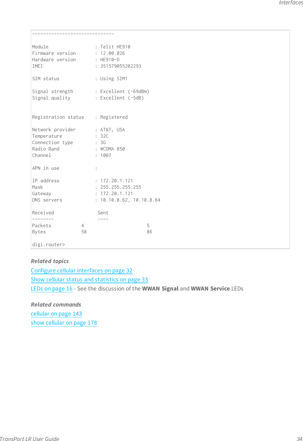
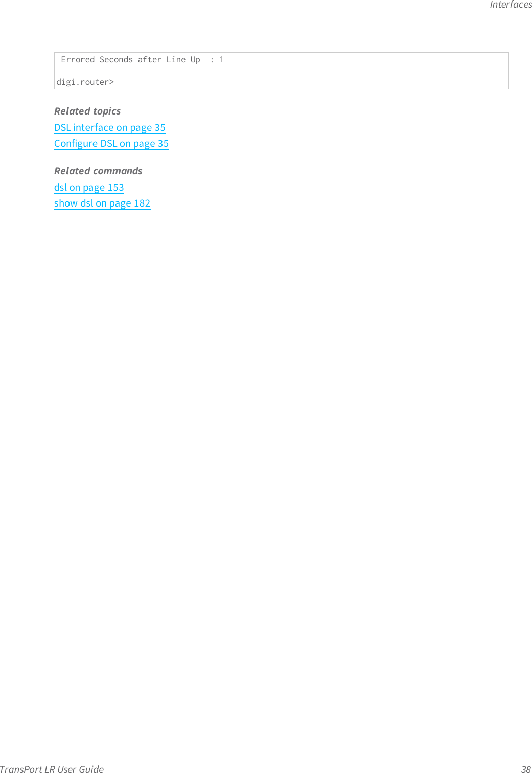
![InterfacesTransPort LR User Guide 37Related topicsDSL interface on page 35Show DSL status and statistics on page 37LEDs on page 16Related commandsdsl on page 153show dsl on page 182Show DSL status and statisticsTo show the status and statistics for the DSLinterface, use the show dsl on page 182 command. Fordescriptions of the output fields, see show dsl on page 182. For example:digi.router> show dslDSL Status and Statistics-------------------------Description :Admin Status : UpOper Status : UpUp Time : 6 Hours, 2 Minutes, 12 SecondsHW Version : T14.F7_12.0FW Version : 3.22.13.0_A60394System FW ID : 3.6.20.0(Y09.ZZ.5)3.22.13.0 20151216_v035 [Dec 16 2015 16:59:11]Line Status : Up (6 Hours, 2 Minutes, 9 Seconds)Mode : ADSL2+Encapsulation : PPPoE, LLCVPI/VCI : 0/35MTU : 1492Remote Vendor ID : ffb54753504e0010 (GSPN)IP Address : 10.10.10.0Netmask : 255.255.255.255Gateway : 1.2.3.4Received Sent-------- ----Packets 13 27Bytes 746 1934Downstream Upstream---------- --------Speed (kbps) 23919 1213Channel Type Interleaved InterleavedRelative Capacity (%) 100 100Attenuation (dB) 0.4 1.1Noise Margin (dB) 6.2 10.5Output Power (dBm) 20.4 2.5FEC 0 1505CRC 0 0HEC 0 0Errored Seconds in 15 Minutes : 0Errored Seconds in 24 Hours : 1](https://usermanual.wiki/Digi/50M1899/User-Guide-3020549-Page-32.png)

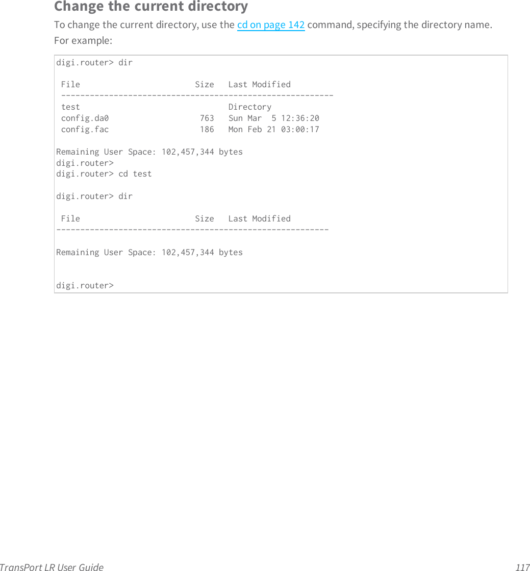
![Command descriptionsTransPort LR User Guide 142cdChanges the current directory.Syntaxcd [dir]ParametersdirWhen a directory name is specified, 'cd' changes the current directory to it.](https://usermanual.wiki/Digi/50M1899/User-Guide-3020549-Page-95.png)
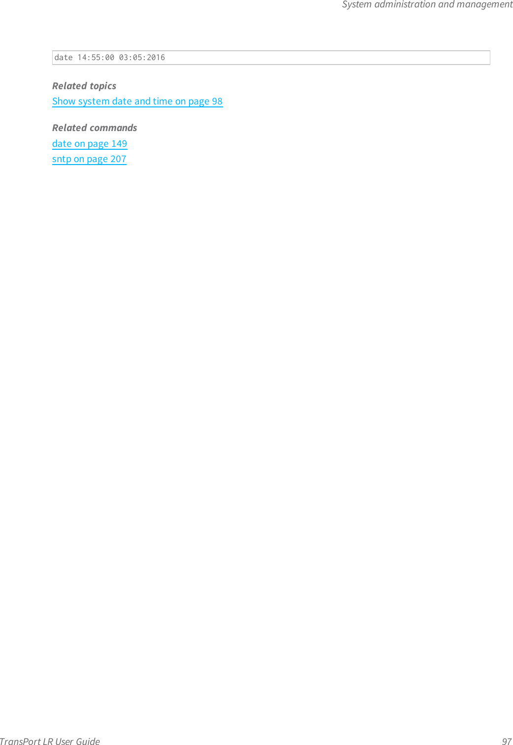
![Command descriptionsTransPort LR User Guide 149dateManually sets and displays the system date and time.Syntaxdate [HH:MM:SS [DD:MM:YYYY]]ParameterstimeSystem time, specified in the 24-hour format HH:MM:SS.dateSystem date, specified in the format DD:MM:YYYY.Examplesndate 14:55:00 03:05:2016Set the system date and time to 14:55:00 on May 3, 2016.](https://usermanual.wiki/Digi/50M1899/User-Guide-3020549-Page-102.png)
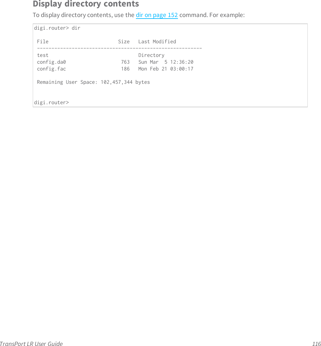
![Command descriptionsTransPort LR User Guide 152dirDisplays the contents of the current directory.Syntaxdir [file]ParametersfileLists information about the file (by default, the current directory).](https://usermanual.wiki/Digi/50M1899/User-Guide-3020549-Page-105.png)
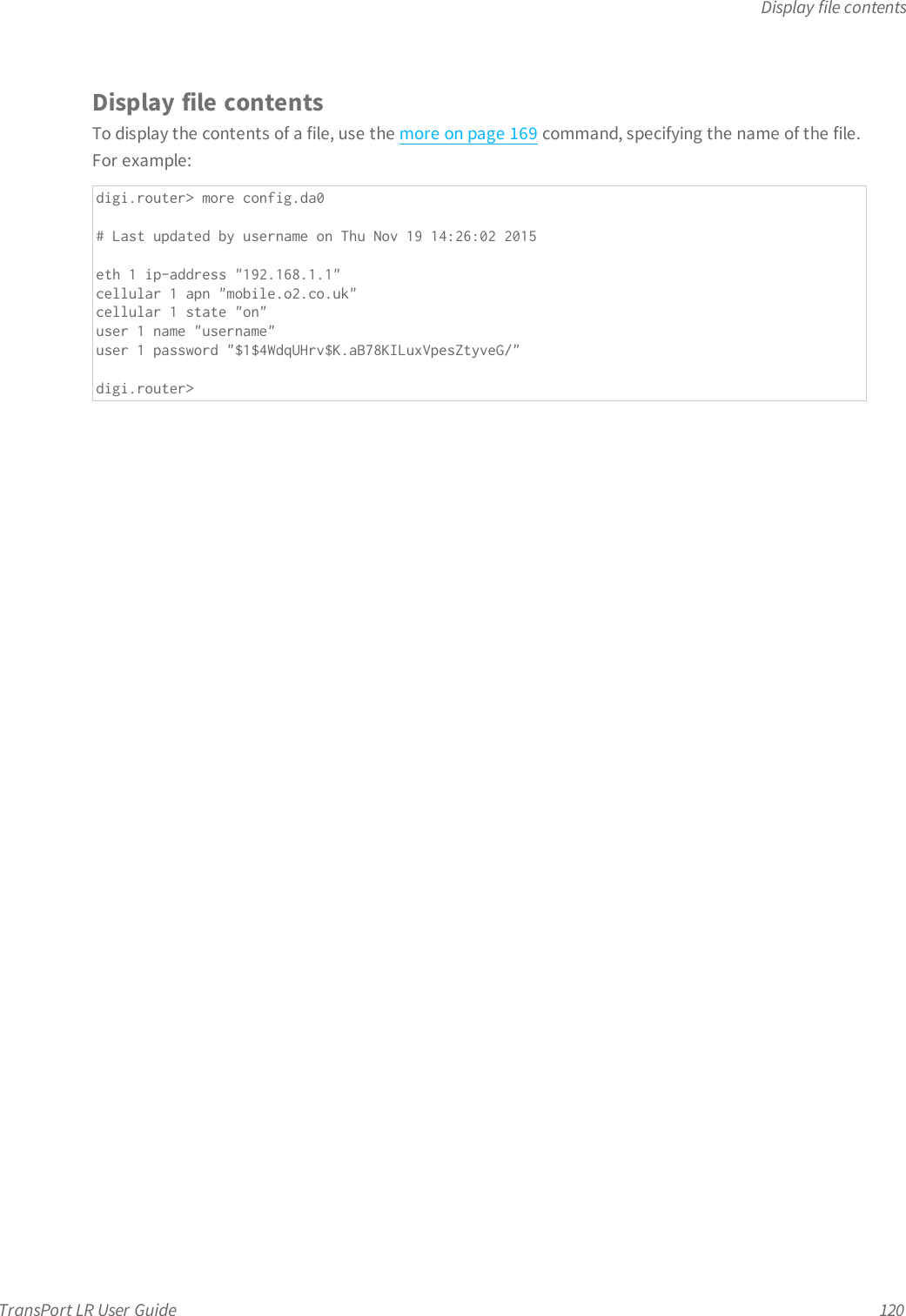
![Command descriptionsTransPort LR User Guide 169moreDisplays the contents of a file.Syntaxmore [file]ParametersfileFile to be displayed.](https://usermanual.wiki/Digi/50M1899/User-Guide-3020549-Page-122.png)
![Command descriptionsTransPort LR User Guide 170pingSends ICMP echo (ping) packets to the specified destination address.Syntaxping [count n] [interface ifname] [size bytes] destinationParameterscountNumber of pings to send.interfaceThe interface from which pings are sent.sizeThe number of data bytes to send.destinationThe name of the IP host to ping.Examplesnping 8.8.8.8Ping IP address 8.8.8.8 with packets of default size 56 bytesnping count 10 size 8 8.8.8.8Ping IP address 8.8.8.8 for 10 timesnping interface eth2 count 5 8.8.8.8Ping IP address 8.8.8.8 for 5 times via Ethernet interface 2](https://usermanual.wiki/Digi/50M1899/User-Guide-3020549-Page-123.png)
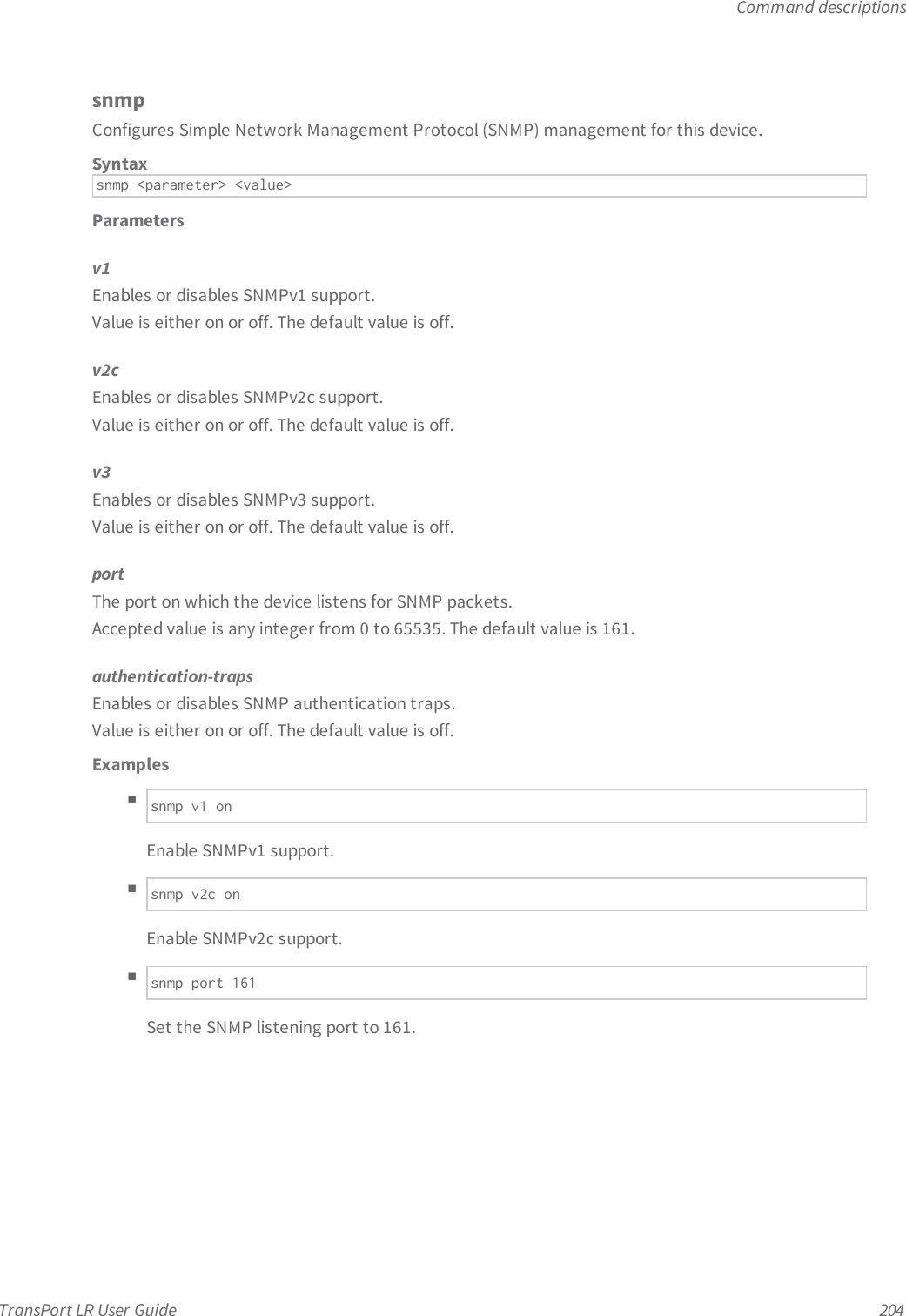
![Command descriptionsTransPort LR User Guide 172rebootReboots the device immediately or at a scheduled time. Performing a reboot will not automaticallysave any configuration changes since the configuration was last saved.This command is available to all users.Syntaxreboot [[in M][at HH:MM][cancel]]ParametersinFor a scheduled reboot, the minutes before the device is rebooted.atFor a scheduled reboot, the time to reboot the device, specified in the format HH:MM.cancelCancels a scheduled reboot.](https://usermanual.wiki/Digi/50M1899/User-Guide-3020549-Page-125.png)


![Command descriptionsTransPort LR User Guide 211updatePerforms system updates, such as firmware updates, setting the cellular carrier, and setting theconfiguration file used at bootup and when saving configuration. Firmware update options includespecifying the device firmware, the cellular module firmware, and the DSL modem firmware to loadonto the device.Syntaxupdate [firmware | module | dsl | config configuration-file]ParametersfirmwareUpdates the firmware of the device.moduleUpdates the cellular module firmware.dslUpdates the DSL modem firmware.configSets the configuration filename.Examplesnupdate config config.da1Set the configuration file to 'config.da1.'nupdate firmware filenameInitiate the router firmware update process.nupdate module filenameInitiates the module firmware update process.nupdate dsl filenameInitiates the DSL modem firmware update process.](https://usermanual.wiki/Digi/50M1899/User-Guide-3020549-Page-164.png)