Digi 50M1899 TransPort LR54 User Manual TransPort LR User Guide
Digi International Inc TransPort LR54 TransPort LR User Guide
Digi >
Users Manual_rev 4

TransPort LR User Guide
User Guide

TransPort LR User Guide
90001461
Revision Date Description
A April 2016 Initial revision.
Trademarks and copyright
Digi, Digi International, and the Digi logo are trademarks or registered trademarks in the United
States and other countries worldwide. All other trademarks mentioned in this document are the
property of their respective owners.
© 2016 Digi International Inc. All rights reserved.
Disclaimers
Information in this document is subject to change without notice and does not represent a
commitment on the part of Digi International. Digi provides this document “as is,” without warranty
of any kind, expressed or implied, including, but not limited to, the implied warranties of fitness or
merchantability for a particular purpose. Digi may make improvements and/or changes in this
manual or in the product(s) and/or the program(s) described in this manual at any time.
Warranty
To view product warranty information, go to the following website:
http://www.digi.com/howtobuy/terms
Send comments
To provide feedback on this document, send your comments to techcomm@digi.com.
Customer support
Digi Technical Support: Digi offers multiple technical support plans and service packages to help our
customers get the most out of their Digi product. For information on Technical Support plans and
pricing, contact us at 877.912.3444 or visit us at www.digi.com/support.
Online: www.digi.com/support/eservice
TransPort LR User Guide 2

TransPort LR User Guide 3
Contents
TransPort LR User Guide 2
TransPort LR Family User Guide
Hardware
TransPort LR54 hardware 9
Hardware summary 10
Hardware specifications 10
Serial connector pinout 15
LEDs 16
Antenna information 19
Regulatory and safety statements 20
Certifications 24
Management and status
Interfaces 27
Ethernet interfaces 28
Cellular interfaces 32
DSL interface 35
Wi-Fi interfaces 39
Serial interfaces 44
Local Area Networks (LANs) 46
Example LAN 46
Configure a LAN 47
Show LAN status and statistics 49
DHCP servers 50
Wide Area Networks (WANs) 52
Ethernet interfaces 52
Cellular interfaces 52
DSL interface 52
WAN failover 53
Configure a WANinterface 54
Example WAN failover: DSLto cellular 57

TransPort LR User Guide 4
Show WAN status and statistics 59
Security 60
User management 61
Firewalls 64
Alarms 65
Services and applications 66
Auto-run commands 67
Python 68
SSH server 69
Remote management 71
Remote Manager 72
Simple Network Management Protocol (SNMP) 73
Routing 76
IP routing 77
Virtual Private Networks (VPN) 83
System administration and management 94
Display and set system information settings 95
Set system date and time 96
Show system date and time 98
Updating firmware 99
Managing configuration files 102
Back up and restore device configuration settings 109
Reboot the device 109
Reset the device to factory defaults 109
Diagnostics 111
Event log 111
Use the "ping" command to troubleshoot network connections 112
Use the "traceroute" command to diagnose IProuting problems 112
Execute a command 113
File system
Make a directory 115
Display directory contents 116
Change the current directory 117
Remove a directory 118
Display file contents 120
Copy a file 121
Rename a file 122
Delete a file 123
Upload and download files 124
Upload files using SCP 124
Download files using SCP 124
Upload files using SFTP 124
Download files using SFTP 124
Troubleshooting
Common issues 127
Cellular issues 127
DSL issues 127
Wi-Fi issues 127
Serial issues 127

TransPort LR User Guide 5
Firewall issues 127
IPsec issues 127
Failover issues 127
User and authentication issues 127
SNMP issues 127
Firmware update issues 127
Troubleshooting tools and resources 128
Status displays 128
Event log 128
Display the event log 128
Clear the event log 129
Use the "ping" command to troubleshoot network connections 129
Use the "traceroute" command to diagnose IProuting problems 129
Reboot the device 130
Reset the device to factory defaults 130
Digi support site 131
Digi knowledge base 131
Need more help? 132
Command reference
Command-line interface basics 134
Command-line interface access options 134
Log in to the command line interface 134
Exit the command line interface 135
Display command and parameter help using the ? character 135
Revert command elements using the ! character 136
Auto-complete commands and parameters 136
Enter configuration commands 136
Save configuration settings to a file 137
Switch between configuration files 137
Display status and statistics using "show" commands 138
Enter file management commands 138
Clear logs and statistics 139
Update firmware and other device features 139
Command descriptions 140
autorun 141
cd 142
cellular 143
clear 145
cloud 146
copy 147
cpu 148
date 149
del 150
dhcp-server 151
dir 152
dsl 153
eth 156
firewall 158
failover 159
ip 161
ipsec 162
ipsec-failover 166

TransPort LR User Guide 6
lan 167
mkdir 168
more 169
ping 170
pwd 171
reboot 172
rename 173
rmdir 174
route 175
save 176
serial 177
show cellular 178
show cloud 180
show config 181
show dsl 182
show eth 186
show failover 189
show firewall 190
show ipsec 191
show ipstats 193
show lan 195
show log 196
show route 197
show serial 198
show system 199
show wan 201
show wifi 202
show wifi5g 203
snmp 204
snmp-community 205
snmp-user 206
sntp 207
ssh 208
system 209
update 211
user 212
wan 213
wifi 215
wifi5g 216
TransPort LR User Guide 7
TransPort LR Family User Guide
The TransPort LRFamily is a family of routers designed for connecting distributed retail terminals
(signs, kiosks, vending machines, point-of-care terminals) with business applications. Key features of
TransPort LRrouters include:
nDual SIM cellular interfaces, providing redundancy
nGobi 4G LTE, for flexibility
nLocal command-line and web interfaces
nSuperior network performance management through Digi Remote Manager (DRM)
nWhat other features do we want to cover here? Easy device setup through a wizard?
Programmability?

TransPort LR User Guide 8
Hardware
This section provides hardware specifications, reviews key hardware features, and lists regulatory
statements and certifications for TLR Family products.
TransPort LR User Guide 10
Hardware summary
Figures, callouts, and descriptions of TLRFamily models to be added here.
Hardware specifications
TransPort LR devices have the following hardware specifications:
Environmental specifications
Specification Value
Operating
temperature
-20C to +70C (-4 to 158F)*
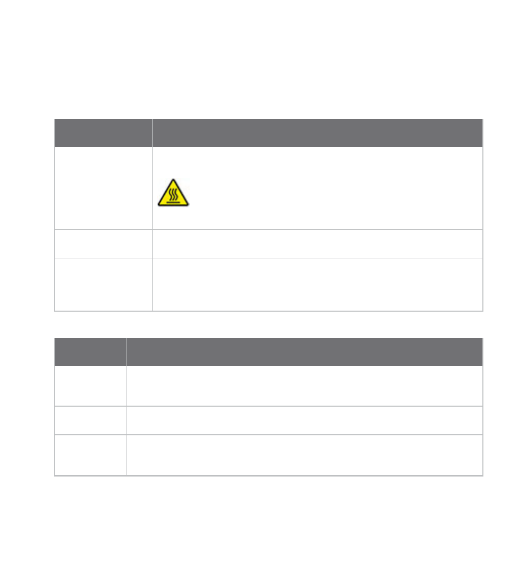
*Note: To limit unintentional contact with HOT SURFACES, install
the device in a Restricted Access Location above +60C.
Relative humidity 10% to 90% RH non-condensing
Storage and
transport
temperature
-40 to 85C (-40 to 185F)
Power requirements
Specification Value
Power input
type
DC
Voltage input 12V +/- 10%
Power
consumption
1.5A

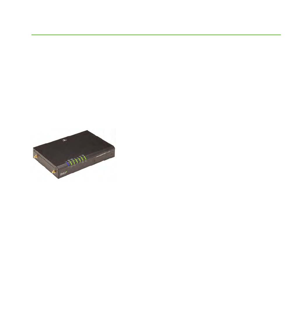
TransPort LR54 hardware
TransPort LR User Guide 11
Specification Value
Power
connector
4-pin Molex 39301040 connector (Digi part number 2312-0012), or equivalent.
Two pins are used for power; the other two pins are no-connect.
Dimensions
Specification Value
Width 20.7 cm (8.15 in)
Depth 13.85 cm (5.45 in)
Height 3.8 cm (1.5 in)
Weight 1.41 kg (3.1 lb)
Ethernet specifications
Specification Value
Ethernet ports 4 RJ45 shielded Ethernet ports
Physical layer 10/100 Base-T (Auto-MDIX)
Data rate 10Mbps, 100Mbps, 1Gbps
Mode Full or half duplex (auto-sensing)
Ethernet isolation 2250VDC

TransPort LR54 hardware
TransPort LR User Guide 12
Cellular specifications
Model Specification Value
TransPort LR54-AA401
TransPort LR54-AW401
Technology LTE, HSPA+,
UMTS
Downstream rates 300 Mbps (LTE),
42 Mbps (HSPA+)
Upstream rates 50 Mbps (LTE),
5.76 Mbps
(HSPA+)
Frequency Bands LTE: 800, 850,
900, 1800, 1900,
2100 AWS, 2300,
2600 MHz
HSPA+, UMTS:
850, 900, AWS
1700, 1900, 2100
MHz
TransPort LR54-DA301 Technology HSPA+, UMTS,
GSM/GPRS/EDGE
Downstream rates 21 Mbps (HSPA+),
384 Kbps (UMTS),
296 Kbps (EDGE)
Upstream rates 5.76 Mbps
(HSPA+),
384 Kbps (UMTS),
236.8 Kbps
(EDGE)
Frequency Bands HSPA+, UMTS:
800, 850, 900,
1700, 1900, 2100
MHz
GSM/GPRS/EDGE:
850, 900, 1800,
1900 MHz

TransPort LR54 hardware
TransPort LR User Guide 13
DSL specifications
Specification Value
DSL ports 1 RJ11DSL port
ADSL line modes Auto (also known as Multimode)
ADSL2+
ADSL2
G.dmt
G.lite
Serial specifications
Specification Value
Serial ports 1 DB9 RS232 DCE serial port, female
Wi-Fi specifications
Specification Value
802.11 a/b/g/n/ac connections, dual band, dual concurrent
2.4GHz and 5GHz
Wi-Fi Modes Wi-Fi access point mode
Wi-Fi client mode
Wi-Fi Security WPA2 Personal
Mixed WPA/WPA2 Personal
WPA2 Enterprise
Mixed WPA/WPA2 Enterprise
Wi-Fi transmit power 2.4GHz:
US variant: 13dBm (802.11g/n), 16dBm (802.11b)
EU variant: 11dBm (802.11g/n), 14dBm (802.11b)
5GHz:
13dBm for all modes
Wi-Fi maximum data rates 54Mbps (802.11a)
11Mbps (802.11b)
54Mbps (802.11g)
300Mbps (802.11n)
866Mbps (802.11ac)

TransPort LR54 hardware
TransPort LR User Guide 15
Serial connector pinout
TransPort LR54 products are DCE devices. The pinout for the DB9 and RJ45 serial connectors is as
follows:
Signal name
RS232
signal
DCE signal
direction
DB9 pin
number
RJ45 pin
number
Transmit Data TxD in 3 6
Receive Data RxD out 2 3
Ready To Send RTS in 7 1
Clear to Send CTS out 8 8
Data Set Ready DSR out 6 4
Ground GND N/A 5 5
Data Carrier Detect DCD out 1 7
Data Terminal Ready DTR in 4 2
Ring Indicate RI out Not
connected
N/A

TransPort LR54 hardware
TransPort LR User Guide 16
LEDs
The TransPort LR54 has LEDs on the top front panel. The number of LEDs varies by model. During
bootup, the front-panel LEDs light up in sequence to indicate boot progress. For example, here are
the LEDs for a TransPort LR54 Wi-Fi model:
There are also several LEDs on the rear WAN/LAN connectors that indicate network link and activity.
Power
nOff: No power.
nBlue: Unit has power.
WWAN Signal
Indicates strength of cellular signal.
4G connections
nOff: No service.
nYellow: Poor / Fair signal.
nGreen: Good / Excellent signal.
Tips for improving cellular signal strength:
If the WWAN Signal LED is yellow or off, try the following things to improve signal strength:
nMove the TransPort LR device to another location.
nPurchase a Digi Antenna Extender Kit:
lAntenna Extender Kit, 1m (76000954)
lAntenna Extender Kit, 3m (76000955)
3Gand 2G connections only
For 3G and 2G cellular connections, the current RSSI value serves as the signal strength indicator,
with the following thresholds:
n> -70dBm: Excellent
n-70dBm to -85dBm: Good
n-86dBm to -100dBm: Fair
n< -100dBm: Poor
n-110dBm: No service
WWAN Service
Indicates the presence and level of cellular service running on the device.

TransPort LR54 hardware
TransPort LR User Guide 17
nOff: No service.
nBlinking Green: 2G/3G/4G connection is coming up.
nSolid Yellow: 2G or 3G connection is up.
nSolid Green: 4G connection is up.
SIM1
Indicates use of the SIM card installed in SIM slot 1.
nOff: SIM 1 is not being used.
nSolid green: SIM 1 is being used or is coming up.
SIM 2
Indicates use of the SIM card installed in SIM slot 2.
nOff: SIM 2 is not being used.
nSolid green: SIM 2 is being used or is coming up.
nNote SIM1 and SIM2 are never on both on at the same time.
DSL (DSL models only)
Indicates state of and activity on the DSL interface.
nOff: DSL interface is off.
nSlow blinking green: DSL interface is attempting to train up with the DSLAM.
nFast blinking green: DSL interface is trained up with the DSLAM, and the PPP interface is
being brought up.
nSolid green: DSL interface is up and can pass IP traffic.
Wi-Fi 2.4GHz LED (Wi-Fi models only)
Indicates state and activity on the Wi-Fi 2.4GHz interface.
nOff: Wi-Fi 2.4GHz interface is disabled.
nSolid green: Wi-Fi 2.4GHz interface is enabled.
nBlinking green: Indicates Wi-Fi traffic on the interface.
Wi-Fi 2.5GHz LED (Wi-Fi models only)
Indicates state of and activity on the Wi-Fi 2.5GHz interface.
nOff: Wi-Fi 5GHz interface is disabled.
nSolid green: Wi-Fi 5GHz interface is enabled.
nBlinking green: Indicates Wi-Fi traffic on the interface.
Ethernet 1-4 Link and Activity (on rear panel)
These LEDs indicate that the Ethernet network interface is up and there is activity on the network
interface.

TransPort LR54 hardware
TransPort LR User Guide 18
nOff: No Ethernet link detected.
nSolid green: Ethernet link detected.
nBlinking green: Indicates Ethernet traffic.

TransPort LR54 hardware
TransPort LR User Guide 20
Regulatory and safety statements
The following regulatory and safety statements apply to TransPort LR devices.
RF exposure statement
In order to comply with RF exposure limits established in the ANSI C95.1 standards, the distance
between the antenna or antennas and the user should not be less than 20 cm.
FCC Part 15 Class B
Radio Frequency Interface (RFI) (FCC 15.105)
This device has been tested and found to comply with the limits for Class B digital devices pursuant
to Part 15 Subpart B, of the FCC rules. These limits are designed to provide reasonable protection
against harmful interference in a residential environment. This equipment generates, uses, and can
radiate radio frequency energy, and if not installed and used in accordance with the instruction
manual, may cause harmful interference to radio communications. However, there is no guarantee
that interference will not occur in a particular installation. If this equipment does cause harmful
interference to radio or television reception, which can be determined by turning the equipment off
and on, the user is encouraged to try and correct the interference by one or more of the following
measures:
nReorient or relocate the receiving antenna.
nIncrease the separation between the equipment and receiver.
nConnect the equipment into an outlet on a circuit different from that to which the receiver is
connected.
nConsult the dealer or an experienced radio/TV technician for help.
Labeling Requirements (FCC 15.19)
This device complies with Part 15 of FCC rules. Operation is subject to the following two conditions:
(1) this device may not cause harmful interference, and (2) this device must accept any interference
received, including interference that may cause undesired operation.
If the FCC ID is not visible when installed inside another device, then the outside of the device into
which the module is installed must also display a label referring to the enclosed module FCC ID.
Modifications (FCC 15.21)
Changes or modifications to this equipment not expressly approved by Digi may void the user’s
authority to operate this equipment.

TransPort LR54 hardware
TransPort LR User Guide 21
European Community - CE Mark Declaration of Conformity (DoC)
EU Declaration Of Conformity
We, of
Manufacturer's Name: Digi International inc.
Manufacturer's Address: 11001 Bren Road East
Minnetonka, MN 55343
declare under our sole responsibility that the product:
Product Name: TransPort LR54
Model Number: 50001899-XX, (X=0~9)
to which this declaration relates are in conformity with the essential requirements and other
relevant requirements of EU Directive 2014/30/EU (EMC),EU Directive 2014/35/EU (LV) and
EU Directive 2011/65/EU (RoHS2)
Safety: EN 62368-1:2014
EN 50564:2011
EN 50385:2002
Comm: EN 50585:2014
EMC: EN 300 328 v1.9.1 (2015-02)
EN 301 489-1 v1.9.2 (2011-09)
EN 301 489-7 v1.3.1 (2005-11)
EN 301 489-17 v2.2.1 (2012-09)
EN 301 489-24 v1.5.1 (2010-10)
EN 55024:2010
EN 55022:2010 + AC:2011, Class B
EN 300 386 v1.6.1 (2012-09)
EN 61000-3-2:2014, Class A
EN 61000-3-3:2013
EN 61000-4-2:2009
EN 61000-4-3:2006 + A1:2008 + A2:2010
EN 61000-4-4:2012
EN 61000-4-5:2014
EN 61000-4-6:2014
EN 61000-4-11:2004
RoHS2: EN 50581:2012
Minnesota, USA, 15th, April 2016
(Place and date of issue) Authorised signature for and on
behalf of Digi International Inc.
Joel Young,VP,Engineering
European
Representative
:
Andreas Burghart
Digi International
GmbH Lise-Meitner-
StraRe 9 85737 lsmani
ng Germany
Telephone:+49-89-540-428-0
9100XXXX
Template 96000759E
Page 1 of 1

TransPort LR54 hardware
TransPort LR User Guide 23
5.10 Ignition of Flammable Atmospheres
Warnings for Use of Wireless Devices
Observe all warning notices regarding use of wireless devices.
Potentially Hazardous Atmospheres
Observe restrictions on the use of radio devices in fuel depots, chemical plants, etc. and areas where
the air contains chemicals or particles, such as grain, dust, or metal powders, and any other area
where you would normally be advised to turn off your vehicle engine.
Safety in Aircraft
Switch off the wireless device when instructed to do so by airport or airline staff. If the device offers
a ‘flight mode’ or similar feature, consult airline staff about its use in flight.
Safety in Hospitals
Wireless devices transmit radio frequency energy and may affect medical electrical equipment.
Switch off wireless devices wherever requested to do so in hospitals, clinics, or health care facilities.
These requests are designed to prevent possible interference with sensitive medical equipment.
Pacemakers
Pacemaker manufacturers recommended that a minimum of 15cm (6 inches) be maintained
between a handheld wireless device and a pacemaker to avoid potential interference with the
pacemaker. These recommendations are consistent with independent research and
recommendations by Wireless Technology Research.
Persons with Pacemakers:
nShould ALWAYS keep the device more than 15cm (6 inches) from their pacemaker when
turned ON.
nShould not carry the device in a breast pocket.
nIf you have any reason to suspect that the interference is taking place, turn OFF your device.

TransPort LR54 hardware
TransPort LR User Guide 24
Certifications
International EMC (Electromagnetic Compatibility) and safety standards
This product complies with the requirements of following Electromagnetic Compatibility standards.
There are no user-serviceable parts inside the product. Contact your Digi representative through for
repair information.
Electromagnetic Compatibility (EMC) compliance
standards Safety compliance standards
EN 300 328 v1.8.1
EN 301 893 v1.7.2
EN 301 489
FCC Part 15 Subpart B Class B
FCC Part 15 Subpart C certification (Integrated Wi-Fi +
Cellular Modules)
EN 62368

TransPort LR User Guide 26
Management and status
These topics show how to configure and view status of various TransPort LR device features.

Interfaces
TransPort LR User Guide 27
Interfaces
Configurable network interfaces available depend on the TransPort LR device model. This section
covers configuring network interfaces from the web interface and command line.

Interfaces
TransPort LR User Guide 28
Ethernet interfaces
The Ethernet interfaces can be used as WAN or LAN interfaces. There is no IP configuration set on the
individual Ethernet interfaces. Instead, the IP configuration is done on the WAN and LAN interfaces.
Related topics
Configure Ethernet interfaces on page 28
Show Ethernet status and statistics on page 29
For more information on WAN interfaces and their configuration, see Wide Area Networks (WANs) on
page 52
For more information on LAN interfaces and their configuration, see Local Area Networks (LANs) on
page 46
Related commands
eth on page 156
show eth on page 186
Configure Ethernet interfaces
To configure an Ethernet interface, you must configure the following items:
Required configuration items
nEnable the Ethernet interface. The Ethernet interfaces are all enabled by default.
Additional configuration options
The following additional configuration settings are not typically configured to get an Ethernet
interface working, but can be configured as needed:
nA description of the Ethernet interface.
nThe duplex mode of the Ethernet interface. This defines how the Ethernet interface
communicates with the device to which it is connected. The duplex mode defaults to auto,
which means the TransPort LR device negotiates with the connected device on how to
communicate.
nThe speed of the Ethernet interface. This defines the speed at which the Ethernet interface
communicates with the device to which it is connected. The Ethernet speed defaults to auto,
which means it negotiates with the connected device as to what speed should be used.
From the command line
1. Enable the Ethernet interface. By default, all of the Ethernet interfaces are enabled.
eth 1 state on
2. Optional: Set the description for the Ethernet interface. For example:
eth 1 description “Connected to DSL WAN router”

Interfaces
TransPort LR User Guide 29
3. Optional: Set the duplex mode.
eth 1 duplex {auto | full | half}
4. Optional: Set the speed.
eth 1 speed {auto | 1000 | 100 | 10}
Related topics
Ethernet interfaces on page 28
Show Ethernet status and statistics on page 29
Related commands
eth on page 156
show eth on page 186
Show Ethernet status and statistics
To show the status and statistics for the DSLinterface, use the show eth on page 186 command. For
descriptions of the output fields, see show dsl on page 182. For example:
digi.router> show eth
Eth Status and Statistics Port 1
-------------------------------------
Description : Factory default configuration for Ethernet 1
Admin Status : Up
Oper Status : Up
Up Time : 1 Day, 13 Hours, 30 Minutes, 23 Seconds
MAC Address : 00:50:18:21:E2:82
DHCP : off
IP Address : 10.52.19.242
Netmask : 255.255.255.0
DNS Server(s) :
Link : 1000Base-T Full-Duplex
Received Sent
-------- ----
Rx Unicast Packet : 6198 Tx Unicast Packet : 651
Rx Broadcast Packet : 316403 Tx Broadcast Packet : 2
Rx Multicast Packet : 442690 Tx Multicast Packet : 6
Rx CRC Error : 0 Tx CRC Error : 0
Rx Drop Packet : 0 Tx Drop Packet : 0
Rx Pause Packet : 0 Tx Pause Packet : 0
Rx Filtering Packet : 1 Tx Collision Event : 0
Rx Alignment Error : 0
Rx Undersize Error : 0
Rx Fragment Error : 0
Rx Oversize Error : 0
Rx Jabber Error : 0
Eth Status and Statistics Port 2
-------------------------------------

Interfaces
TransPort LR User Guide 30
Description :
Admin Status : Up
Oper Status : Up
Up Time : 1 Day, 13 Hours, 30 Minutes, 23 Seconds
MAC Address : 00:50:18:21:E2:83
DHCP : off
IP Address : 10.2.4.20
Netmask : 255.255.255.0
DNS Server(s) :
Link : 100Base-T Full-Duplex
Received Sent
-------- ----
Rx Unicast Packet : 5531 Tx Unicast Packet : 2
Rx Broadcast Packet : 316403 Tx Broadcast Packet : 2
Rx Multicast Packet : 442694 Tx Multicast Packet : 2
Rx CRC Error : 0 Tx CRC Error : 0
Rx Drop Packet : 0 Tx Drop Packet : 0
Rx Pause Packet : 0 Tx Pause Packet : 0
Rx Filtering Packet : 0 Tx Collision Event : 0
Rx Alignment Error : 0
Rx Undersize Error : 0
Rx Fragment Error : 0
Rx Oversize Error : 0
Rx Jabber Error : 0
Eth Status and Statistics Port 3
-------------------------------------
Description :
Admin Status : Up
Oper Status : Up
Up Time : 1 Day, 13 Hours, 30 Minutes, 23 Seconds
MAC Address : 00:50:18:21:E2:84
DHCP : on
IP Address : 82.68.87.20
Netmask : 255.255.255.0
DNS Server(s) :
Link : 100Base-T Full-Duplex
Received Sent
-------- ----
Rx Unicast Packet : 5530 Tx Unicast Packet : 2
Rx Broadcast Packet : 316405 Tx Broadcast Packet : 2
Rx Multicast Packet : 442699 Tx Multicast Packet : 4
Rx CRC Error : 0 Tx CRC Error : 0
Rx Drop Packet : 0 Tx Drop Packet : 0
Rx Pause Packet : 0 Tx Pause Packet : 0
Rx Filtering Packet : 0 Tx Collision Event : 0
Rx Alignment Error : 0
Rx Undersize Error : 0
Rx Fragment Error : 0
Rx Oversize Error : 0
Rx Jabber Error : 0
Eth Status and Statistics Port 4
-------------------------------------

Interfaces
TransPort LR User Guide 31
Description :
Admin Status : Up
Oper Status : Down
Up Time : 0 Seconds
MAC Address : 00:50:18:21:E2:85
DHCP : on
IP Address : Not Assigned
Netmask : Not Assigned
DNS Server(s) :
Link : No connection
Received Sent
-------- ----
Rx Unicast Packet : 0 Tx Unicast Packet : 0
Rx Broadcast Packet : 0 Tx Broadcast Packet : 0
Rx Multicast Packet : 0 Tx Multicast Packet : 0
Rx CRC Error : 0 Tx CRC Error : 0
Rx Drop Packet : 0 Tx Drop Packet : 0
Rx Pause Packet : 0 Tx Pause Packet : 0
Rx Filtering Packet : 0 Tx Collision Event : 0
Rx Alignment Error : 0
Rx Undersize Error : 0
Rx Fragment Error : 0
Rx Oversize Error : 0
Rx Jabber Error : 0
digi.router>
Related topics
Ethernet interfaces on page 28
Configure Ethernet interfaces on page 28
Related commands
eth on page 156
show eth on page 186

Interfaces
TransPort LR User Guide 32
Cellular interfaces
The TransPort LR device has two cellular interfaces, named cellular1 and cellular2. These cellular
interfaces correspond to the physical SIMcard slots SIM1 and SIM2 respectively.
Both cellular interfaces cannot be up at the same time. If both cellular interfaces are enabled to on,
then cellular1 interface takes precedence.
A typical use case would be to have cellular1 (SIM1) configured as the primary cellular interface and
cellular2 (SIM2) as a backup cellular interface. If the TransPort LR device cannot connect to the
cellular network using SIM1, it will automatically failover to try to connect using SIM2.
For the TransPort LR device to automatically configure a default route for the cellular interface when
it is up and for it to be able to failover to and from the cellular interface, it must be assigned to a WAN
interface.
Related topics
Configure cellular interfaces on page 32
Show cellular status and statistics on page 33
For more information on WAN interfaces and their configuration, see Wide Area Networks (WANs) on
page 52.
LEDs on page 16 - See the discussion of the WWAN Signal and WWANService LEDs
Related commands
cellular on page 143
show cellular on page 178
Configure cellular interfaces
To configure a cellular interface, you need to configure the following:
Required configuration items
Enable the cellular interface. By default, the cellular interfaces are disabled.
nThe Access Point Name (APN). The APN is specific to your cellular service.
nDepending on your cellular service, you may need to configure an APN username and
password. This information is provided by your cellular provider.
nAssign the cellular interface to a WAN interface. For more information on the WAN
configuration, see Wide Area Networks (WANs) on page 52.
Additional configuration options
Additional configuration settings are not typically configured, but you can set them as needed:
nPreferred mode. The preferred mode locks the cellular interface to use a particular
technology, for example, 4G or 3G. Depending on your cellular service and location, the cellular
interface can automatically switch between the different technologies. You may want to lock
the cellular interface to a particular technology to minimize disruptions.
nA description of the cellular interface.

Interfaces
TransPort LR User Guide 33
nConnection attempts. This is the number of attempts the cellular module will attempt to
connect to the cellular network before indicating a failure. It defaults to 20, but you may want
to configure this so that the WAN failover can switch to another interface more quickly.
From the command line
1. Enable the cellular interface.
cellular 1 state on
2. Configure an APN.
cellular 1 apn your-apn
3. If necessary, configure the APN username and password.
cellular 1 apn-username your-apn-username
cellular 1 apn-password your-apn-password
4. Optional: Set a preferred mode.
cellular 1 preferred-mode 3G
5. Optional: Set a description for the cellular interface.
cellular 1 description "AT&T Connection"
6. Optional: Configure the number of connection attempts. For example, to set the number of
attempts to 10, enter:
cellular 1 connection-attempts 10
Related topics
Configure cellular interfaces on page 32
Show cellular status and statistics on page 33
LEDs on page 16 - See the discussion of the WWAN Signal and WWANService LEDs
Related commands
cellular on page 143
show cellular on page 178
Show cellular status and statistics
To show the status and statistics for a cellular interface, use the show lan on page 195 command.
For a description of the output fields, see the show cellular command.
digi.router> show cellular
Cellular Status and Statistics

Interfaces
TransPort LR User Guide 34
------------------------------
Module : Telit HE910
Firmware version : 12.00.026
Hardware version : HE910-D
IMEI : 351579055202293
SIM status : Using SIM1
Signal strength : Excellent (-69dBm)
Signal quality : Excellent (-5dB)
Registration status : Registered
Network provider : AT&T, USA
Temperature : 32C
Connection type : 3G
Radio Band : WCDMA 850
Channel : 1007
APN in use :
IP address : 172.20.1.121
Mask : 255.255.255.255
Gateway : 172.20.1.121
DNS servers : 10.10.8.62, 10.10.8.64
Received Sent
-------- ----
Packets 4 5
Bytes 58 86
digi.router>
Related topics
Configure cellular interfaces on page 32
Show cellular status and statistics on page 33
LEDs on page 16 - See the discussion of the WWAN Signal and WWANService LEDs
Related commands
cellular on page 143
show cellular on page 178

Interfaces
TransPort LR User Guide 35
DSL interface
These topics describe configuring and managing the DSL interface.
Related topics
Configure DSL on page 35
Show DSL status and statistics on page 37
Related commands
dsl on page 153
show dsl on page 182
Configure DSL
To configure the DSL interface to connect to your DSL network, you need to configure the following:
Required configuration items
nEnable the DSL interface.
nVirtual Path Identifier (VPI) and Virtual Circuit Identifier (VCI) parameters. These parameters
are specific to each DSL provider and must be configured to match your provider’s settings.
nData encapsulation for the DSL interface. This parameter is specific to each DSL provider and
must be configured to match your provider’s settings.
nUsername and password. The username and password relate to your account with your DSL
provider. A password is not always needed.
Additional configurable options
The following additional configuration settings are not typically configured to get the DSL interface
connected to the DSL network, but you can set them as needed:
nThe technology used on the DSL line, known as the line mode.
nThe Maximum Transmission Unit (MTU). The MTU defines the maximum size (in bytes) of a
packet that can be sent over the DSL interface.
nNetwork Address Translation (NAT).
nA description of the DSLinterface.
nWhether to delay bringing up the DSL for a specified number of seconds. This delay allows the
DSL provider network to propagate network changes after the device has connected to the
network, and before packets can be sent and received. This delay prevents the device from
assuming the network is fully operational before it actually is fully operational, which could in
turn cause problems with other features, such as interface failover. During this delay, the
DSLLED flashes, to indicate the interface is not fully up. Because characteristics can differ
among provider networks, use of the delay-up parameter is provider-specific.

Interfaces
TransPort LR User Guide 36
From the command line
1. Enable the DSL interface. By default, the DSL interface is disabled. To enable it, enter:
dsl state on
2. Configure VPI and VCI:
dsl vpi <vpi-number>
dsl vci <vci-number>
3. Configure encapsulation:
dsl encapsulation <encapsulation>
4. Set the username and password for the DSL interface:
dsl username <username>
dsl password <password>
5. Optional: Configure line mode. Normally this should be left as auto were the device will
negotiate the mode with the DSL provider. Depending on your DSL line, you may need to
configure the line mode to a particular technology for the device to connect to the DSL
network. To configure line mode, enter
dsl mode <mode>
6. Optional: Set the MTU. The MTU defaults to 1500 and automatically adjusts for the
encapsulation type.
dsl mtu <mtu>
7. Enable or disable NAT on the DSL interface. NAT is enabled by default, and normally, there is
no need to disable it. The command to configure NAT is:
dsl nat <on | off>
8. Optional: Set the description for the DSLinterface. The description parameter allows you to
configure a description for the DSL interface to help you identify it. For example:
dsl description "HQ Server Room"
9. Optional: Set a delay, in seconds, for bringing up the DSL interface. For example, to set a delay
of 60 seconds, enter:
dsl delay-up 60

Interfaces
TransPort LR User Guide 37
Related topics
DSL interface on page 35
Show DSL status and statistics on page 37
LEDs on page 16
Related commands
dsl on page 153
show dsl on page 182
Show DSL status and statistics
To show the status and statistics for the DSLinterface, use the show dsl on page 182 command. For
descriptions of the output fields, see show dsl on page 182. For example:
digi.router> show dsl
DSL Status and Statistics
-------------------------
Description :
Admin Status : Up
Oper Status : Up
Up Time : 6 Hours, 2 Minutes, 12 Seconds
HW Version : T14.F7_12.0
FW Version : 3.22.13.0_A60394
System FW ID : 3.6.20.0(Y09.ZZ.5)3.22.13.0 20151216_v035 [Dec 16 2015 16:59:11]
Line Status : Up (6 Hours, 2 Minutes, 9 Seconds)
Mode : ADSL2+
Encapsulation : PPPoE, LLC
VPI/VCI : 0/35
MTU : 1492
Remote Vendor ID : ffb54753504e0010 (GSPN)
IP Address : 10.10.10.0
Netmask : 255.255.255.255
Gateway : 1.2.3.4
Received Sent
-------- ----
Packets 13 27
Bytes 746 1934
Downstream Upstream
---------- --------
Speed (kbps) 23919 1213
Channel Type Interleaved Interleaved
Relative Capacity (%) 100 100
Attenuation (dB) 0.4 1.1
Noise Margin (dB) 6.2 10.5
Output Power (dBm) 20.4 2.5
FEC 0 1505
CRC 0 0
HEC 0 0
Errored Seconds in 15 Minutes : 0
Errored Seconds in 24 Hours : 1


Interfaces
TransPort LR User Guide 39
Wi-Fi interfaces
Wi-Fi-enabled TransPort LR devices support up to 4 Wi-Fi interfaces on each of the 2.4 GHz and 5 GHz
frequency bands. Each Wi-Fi interface can be configured as an independent Wi-Fi Access Point with its
own security settings.
Related topics
Configure a Wi-Fi access point on page 39
Configure a Wi-Fi access point with WPA2-Enterprise or WPA-WPA2-Enterprise security on page 41
Show Wi-Fi status and statistics on page 42
Related commands
wifi on page 215
wifi5g on page 216
show wifi on page 202
show wifi5g on page 203
Configure a Wi-Fi access point
This section describes how to configure a Wi-Fi 2.4 GHz Access Point and a Wi-Fi 5 GHz Access Point.
Required configuration items
Configuring a Wi-Fi Access Point involves configuring the following items:
nEnabling the Wi-Fi Access Point.
nThe Wi-Fi Access Point’s Service Set Identifier (SSID).
You can configure the SSID to use the device's serial number by including %s in the SSID. For
example, an ssid parameter value of LR54_%s resolves to LR54_LR123456.
nThe password for the Wi-Fi interface. The password only needs to be set if WPA2-Personal or
WPA-WPA2-Personal security is being used.
Additional configuration options
The following additional configuration settings are not typically configured to get an Wi-Fi access
point working, but can be configured as needed:
nThe type of security used on the Wi-Fi interface. The options are as follows. By default, WPA2-
Personal security is used.
lNone: No security is used on the Wi-Fi network.
lWPA2-Personal: a method of securing a Wi-Fi network using WPA2 with the use of the
optional Pre-Shared Key (PSK) authentication. This security method was designed for
home users without an enterprise authentication server.
lWPA/WPA2-Personal. This security method is a mixed mode, providing WPA with
Temporal Key Integrity Protocol (TKIP) encryption or WPA2 with Advanced Encryption
Standard (AES) encryption supported by the Access Point.

Interfaces
TransPort LR User Guide 40
lWPA2-Enterprise: This security method is designed for enterprise networks and requires
a RADIUS authentication server. This security method requires a more complicated setup,
but provides additional security. Various kinds of the Extensible Authentication Protocol
(EAP) are used for authentication.
lWPA/WPA2-Enterprise: This security method is designed for enterprise networks and
requires a RADIUS authentication server. This is a mixed mode method, providing WPA
with TKIP encryption or WPA2 with AES encryption supported by the Access Point.
nA description of the Wi-Fi Access Point.
From the command line
To configure a Wi-Fi 2.4 GHz Access Point, the command-line command is wifi on page 215.
To configure a Wi-Fi 5 GHz Access Point, the command-line command is wifi5g on page 216.
The following steps show using the wifi on page 215 command. When configuring a Wi-FI 5GHz
Access Point, use the wifi5g on page 216 command. The parameters are the same.
1. Enable the Wi-Fi Access Point.
wifi 1 state on
2. Enter the SSID for the Wi-Fi Access Point.
wifi 1 ssid LR54-AP1
3. Enter the password for the Wi-Fi Access Point.
wifi 1 password your-password
4. Optional: Enter the security for the Wi-Fi Access Point.
wifi 1 security wpa-wpa2-personal
5. Optional: Enter a description for the Wi-Fi Access Point.
wifi 1 description “Office AP”
Related topics
Wi-Fi interfaces on page 39
Configure a Wi-Fi access point with WPA2-Enterprise or WPA-WPA2-Enterprise security on page 41
Show Wi-Fi status and statistics on page 42
Related commands
wifi on page 215
wifi5g on page 216
show wifi on page 202
show wifi5g on page 203

Interfaces
TransPort LR User Guide 41
Configure a Wi-Fi access point with WPA2-Enterprise or WPA-WPA2-Enterprise security
The WPA2-Enterprise and WPA-WPA2-Enterprise security modes allow a Wi-Fi Access Point to
authenticate connecting Wi-Fi clients using a RADIUS server.
When the Wi-Fi Access Point receives an connection request from a Wi-Fi client, it will authenticate
the client with the RADIUS server before allowing the client to connect.
Using Enterprise security modes allows for each Wi-Fi client to have different username and
password which are configured in the RADIUS server and not the TransPort LR device.
Configuring a Wi-Fi Access Point to use an Enterprise security mode involves configuring the following
items:
Required configuration items
Configuring a Wi-Fi Access Point to use an Enterprise security mode involves configuring the following
items:
nEnabling the Wi-Fi Access Point.
nThe Wi-Fi Access Point’s Service Set Identifier (SSID).
You can configure the SSID to use the device's serial number by including %s in the SSID. For
example, an ssid parameter value of LR54_%s resolves to LR54_LR123456.
nSetting the security mode to either WPA2-Enterprise or WPA-WPA2-Enterprise.
nRADIUS server IP address.
nRADIUS password.
Additional configuration options
Additional configuration options include:
nRADIUS server port.
nA description of the Wi-Fi Access Point.
From the command line
To configure a Wi-Fi 2.4 GHz Access Point, the command-line command is wifi on page 215.
To configure a Wi-Fi 5 GHz Access Point, the command-line command is wifi5g on page 216.
The following steps show using the wifi on page 215 command. When configuring a Wi-FI 5GHz
Access Point, use the wifi5g on page 216 command. The parameters are the same.
1. Enable the Wi-Fi Access Point.
wifi 1 state on
2. Enter the SSID for the Wi-Fi Access Point.
wifi 1 ssid LR54-AP1
3. Enter the security for the Wi-Fi Access Point.
wifi 1 security wpa2-enterprise

Interfaces
TransPort LR User Guide 42
4. Enter the RADIUS server IP address.
wifi 1 radius-server 192.168.1.200
5. Enter the RADIUS password.
wifi 1 radius-password your-radius-password
6. Optional: Enter the RADIUS server port.
wifi 1 radius-server-port 3001
7. Optional: Enter a description for the Wi-Fi Access Point.
wifi 1 description "Office AP"
Related topics
Wi-Fi interfaces on page 39
Configure a Wi-Fi access point with WPA2-Enterprise or WPA-WPA2-Enterprise security on page 41
Show Wi-Fi status and statistics on page 42
Related commands
wifi on page 215
wifi5g on page 216
show wifi on page 202
show wifi5g on page 203
Show Wi-Fi status and statistics
To show the status and statistics for a Wi-Fi 2.4 GHz interface, use the show wifi on page 202
command. For example:
digi.router> show wifi
Interface Status SSID Security
-------------------------------------------------------------
wifi1 Down WPA2-Personal
wifi2 Up digi.router_2.4g_LR000051 WPA2-Personal
wifi3 Down WPA2-Personal
wifi4 Up digi.router_2.4g None
digi.router>
To show the status and statistics for a Wi-Fi 5 GHz interface, use the show wifi5g on page 203
command. For example:
digi.router> show wifi5g
Interface Status SSID Security
-------------------------------------------------------------
wifi5g1 Down WPA2-Personal

Interfaces
TransPort LR User Guide 43
wifi5g2 Up digi.route_5g_LR000051 None
wifi5g3 Up digi.route_5g WPA2-Personal
wifi5g4 Down WPA2-Personal
digi.router>
Related topics
Wi-Fi interfaces on page 39
Configure a Wi-Fi access point on page 39
Configure a Wi-Fi access point with WPA2-Enterprise or WPA-WPA2-Enterprise security on page 41
Related commands
wifi on page 215
wifi5g on page 216
show wifi on page 202
show wifi5g on page 203
Local Area Networks (LANs)
TransPort LR User Guide 46
Local Area Networks (LANs)
A Local Area Network (LAN) connects networks together, such as Ethernet, DSL, or Wi-Fi, in a logical
Layer-2 network. Networks filter traffic between different segments, thereby reducing the amount
of traffic on a LAN, even with many LAN segments.
You can configure up to 10 LANs.
When an interface joins a LAN, it cannot be directly addressed anymore. This means that an IP
address configured on the interface can no longer be accessed once the network joins the LAN.
Example LAN
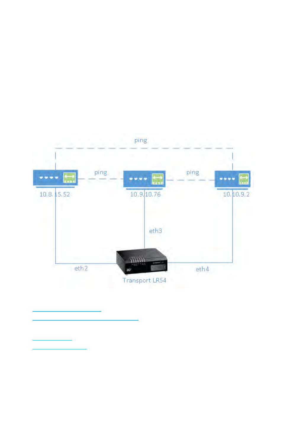
The diagram shows a LAN connecting the eth2,eth3, and eth4 interfaces for a TransPortLR54 unit.
Once the LAN is configured and enabled, the devices connected to the network interfaces can
communicate with each other, as demonstrated by the ping commands.
Related topics
Configure a LAN on page 47
Show LAN status and statistics on page 49
Related commands
lan on page 167
show lan on page 195

Local Area Networks (LANs)
TransPort LR User Guide 47
Configure a LAN
Configuring a Local Area Network (LAN) involves configuring the following items:
Required configuration items
nIdentifying which interfaces are in the LAN.
nEnabling the LAN. LANs are disabled by default.
nSetting an IPv4 address and subnet mask for the LAN. While it is not strictly necessary for a
LAN to have an IP address, if you want to send traffic from other networks to the LAN, you
must configure an IP address.
Additional configuration options
nSetting a name for the LAN.
nSetting the Maximum Transmission Unit, or packet size, for packets sent over the LAN.
From the command line
1. Set the interfaces in the LAN. For example, to include eth2,eth3, and eth4 interfaces in lan1,
enter:
lan 1 interfaces eth2,eth3,eth4
2. Enable the LAN. For example, to enable lan1:
lan 1 state on
3. Optional: Set an IPv4 address for the LAN.
lan 1 ip-address 192.10.8.8
4. Optional: Set a subnet mask for the LAN.
lan 1 mask 255.255.255.0
5. Optional: Give a descriptive name to the LAN.
lan 1 description ethlan
6. Optional: Set the MTU for the LAN.
lan 1 mtu 1500
Related topics
Local Area Networks (LANs) on page 46
Show LAN status and statistics on page 49

Local Area Networks (LANs)
TransPort LR User Guide 49
Show LAN status and statistics
To show the status and statistics for a LAN, use the show lan on page 195 command. For example,
here is show lan output before and after enabling lan1. For a description of the output fields, see the
show lan on page 195 command.
digi.router> show lan 1
LAN 1 Status and Statistics
---------------------------
Admin Status : Up
Oper Status : Up
Description : ethlan
Interfaces : eth2,eth3,eth4
MTU : 1500
IP Address : 192.10.8.8
Network Mask : 255.255.255.0
Received Sent
------------- ------
Packets 624 6
Bytes 48632 468
digi.router>
Related topics
Local Area Networks (LANs) on page 46
Configure a LAN on page 47
Related commands
lan on page 167
show lan on page 195

Local Area Networks (LANs)
TransPort LR User Guide 50
DHCP servers
The DHCP server feature can be enabled in a TransPort LR device to assign IPaddresses and other
IPconfiguration to other hosts on the same local network. Addresses are assigned from a specified
pool of IPaddresses. For a local network, the device will use the DHCP server that has the IPaddress
pool in the same IPsubnet as the local network.
You can configure up to 10 DHCP servers.
When a host receives an IPconfiguration, the configuration is valid for a particular amount of time,
known as the lease time. After this lease time expires, the configuration must be renewed. The host
performs lease-time renewal automatically.
Related topics
Configure DHCP server settings on page 50
Show DHCP server settings on page 51
Related commands
dhcp-server on page 151
Configure DHCP server settings
To configure a DHCP server, you need to configure the following:
Required configuration items
nEnable the DHCP server.
nThe IPaddress pool: the range of IPaddresses issued by the DHCPserver to clients.
nThe IPnetwork mask given to clients.
nThe IPgateway address given to clients.
nThe IPaddresses of the preferred and alternate Domain Name Server (DNS) given to clients.
Additional configuration options
nLease time: The length, in minutes, of the leases issued by the DHCP server.
From the command line
1. Enable the DHCP server. By default, the DHCP server is disabled.
dhcp-server 1 state on
2. Enter the starting address of the IPaddress pool:
dhcp-server 1 ip-address-start 10.30.1.150
3. Enter the ending address of the IPaddress pool:
dhcp-server 1 ip-address-end 10.30.1.195

Local Area Networks (LANs)
TransPort LR User Guide 51
4. Enter the network mask:
dhcp-server 1 netmask 255.255.225.0
5. Enter the IPgateway address given to clients:
dhcp-server 1 gateway 10.30.1.1
6. Enter the preferred DNS server address given to clients:
dhcp-server 1 dns1 10.30.1.1
7. Enter the alternate DNS server address given to clients:
dhcp-server 1 dns2 209.183.48.11
8. Enter the lease time:
dhcp-server 1 lease-time 60
Related topics
DHCP servers on page 50
Show DHCP server settings on page 51
Related commands
dhcp-server on page 151
Show DHCP server settings
To be provided when the show DHCPserver command is added to the firmware.
Wide Area Networks (WANs)
TransPort LR User Guide 52
Wide Area Networks (WANs)
A Wide Area Network (WAN) interface can be an Ethernet, DSL, or cellular interface that connects to a
remote network, such as the internet.
Ethernet interfaces
Ethernet interfaces can be used as a WAN interface when connecting to a remote network, such as
the internet, through a device such as a cable or DSL modem.
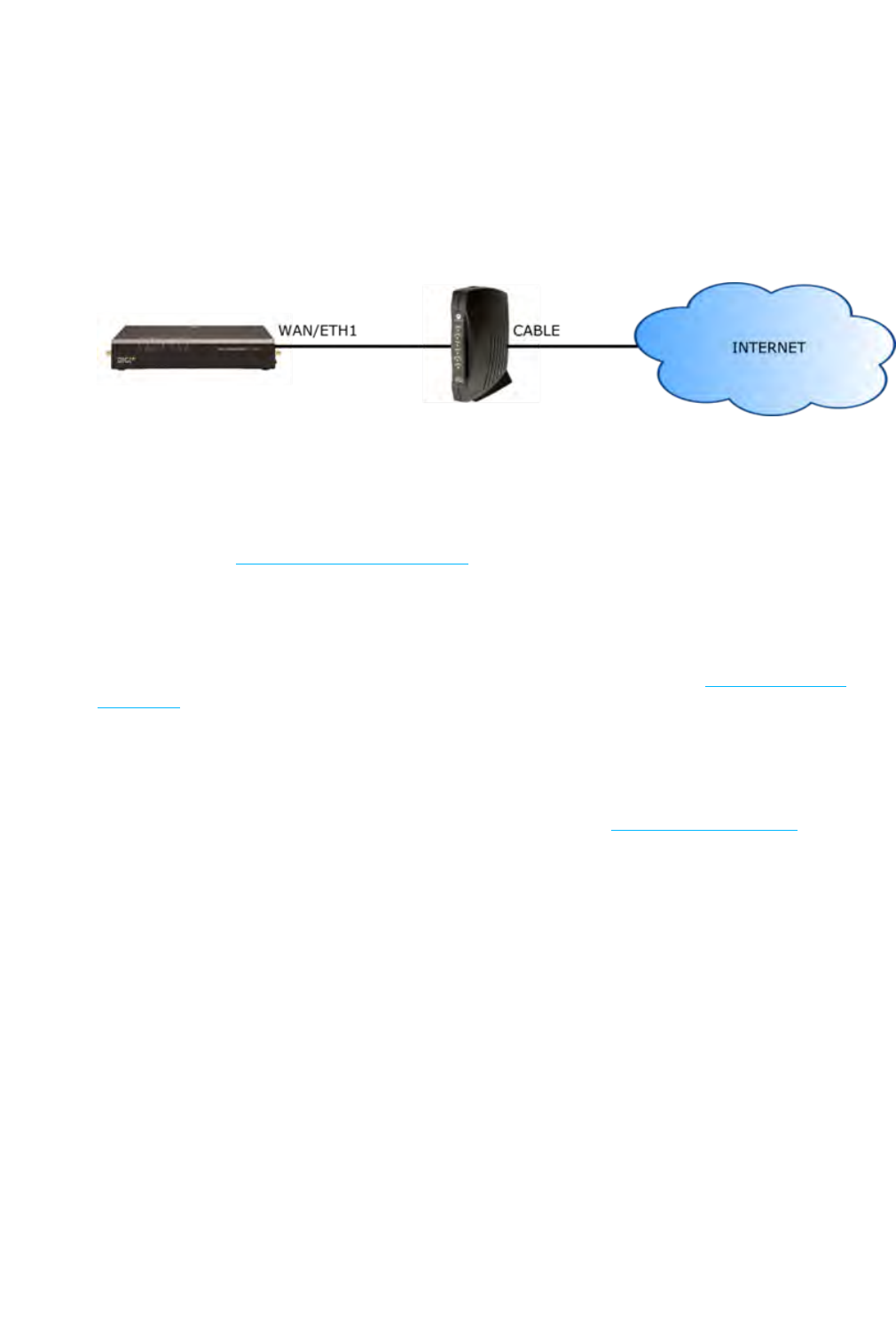
By default, the eth1 interface is configured as a WAN interface with both DHCP and NAT enabled. This
means you should be able to connect to the internet by connecting the wan/eth1 interface to a
device that already has an internet connection.
By default, the eth2,eth3, and eth4 interfaces are configured as a LAN interface. If necessary, you
can assign these interfaces to a WAN. For more information on Ethernet interfaces and their
configuration, see Ethernet interfaces on page 28.
Cellular interfaces
The LR54 supports two cellular interfaces, cellular1 and cellular2.
To use a cellular interface as a WAN interface, it must be configured to connect to the cellular
network. For more information on cellular interfaces and their configuration, see Cellular interfaces
on page 32.
DSL interface
The TransPort LR device supports one Asymmetric Digital Subscriber Line (ADSL) interface, dsl.
To use the DSL interface as a WAN interface, you must configure it to connect to the DSL network.
For more information on the DSL interface and its configuration, see DSL interface on page 35.
Related topics

Wide Area Networks (WANs)
TransPort LR User Guide 53
WAN failover
If a WAN interface fails for any reason, the TransPort LR device automatically fails over from one WAN
interface to use another.
For example, if you use an Ethernet interface as your main WAN interface, and have a cellular
interface configured as a backup WAN interface, if the Ethernet interface was to fail (for example, if
the Ethernet cable is broken), the TransPort LR device automatically starts to use the cellular
interface until the Ethernet interface becomes active again.
IP probing
Sometimes, problems can occur beyond the immediate WAN connection that prevent some IP traffic
reaching their destination. Normally this kind of problem does not cause the WAN interface to fail, as
the connection continues to work while the core problem exists somewhere else in the network.
IP probing is a way to detect problems in an IP network. IPprobing involves configuring the
TransPort LR device to send out regular IP probe packets to a particular destination. If responses to
these probe packets are not received, the TransPort LR device can bring down the WAN interface,
and switch to using another WAN interface until the IP network problem is resolved.
IP probing involves the following configuration settings:
nThe IP address or name of the host to probe
nThe size of the IP probe packets
nThe rate at which the IP probe packets are sent
nThe time, in seconds, after which the IP probe response is considered lost
nThe WAN interface timeout, in seconds, if no IP probe responses are received.
nThe time, in seconds, after which the WAN interface must receive all IPprobe responses
before reactivating the WANinterface
nThe time, in seconds, after which the TransPort LR device attempts to bring up the
WANinterface
All of the IP probing configuration has default values, except for the IP address or name of the host to
probe. Use of IP probes requires this IPaddress. For the rest of the parameters, the default values
should be sufficient, but they can be set to different values as needed to suit your WANfailover
requirements.
Related topics
Wide Area Networks (WANs) on page 52
Configure Wi-Fi interfaces
Example WAN failover: DSLto cellular on page 57
Show WAN status and statistics on page 59
Related commands
wan on page 213

Wide Area Networks (WANs)
TransPort LR User Guide 54
Configure a WANinterface
You can configure up to 10 WAN interfaces.
wan1 is the top priority, wan2 is the second priority, and so on.
The TransPort LR device automatically adds a default IP route for the WAN interface when it comes
up. The metric of the route is based on the priority of the interface. For example, as wan1 is the
highest priority, the default route for wan1 has a metric of 1, and the default route for wan2 has a
metric of 2.
Required configuration items
Assign an Ethernet, DSL or Cellular interface to the WAN interface. By default, WAN interfaces are
assigned the following interfaces :
nFor TransPort LR devices with DSL:
lwan1:eth1
lwan2:dsl
lwan3:cellular1
lwan4:cellular2
nFor TransPort LR devices without DSL:
lwan1:eth1
lwan2:cellular1
lwan3:cellular2
Additional configuration options
These additional configuration settings are not typically configured, but you can set them as needed:
nThe IP configuration. WAN interfaces typically get their IP address configuration from the
network, for example, DSL or cellular, to which they connect. However, you can manually set
the IP configuration as needed. The following manual configuration settings are available:
lIP address and mask
lGateway
lPreferred and alternate DNS server
nDisable the DHCP client. Ethernet interfaces use DHCP client to get an IP address from a
DHCP server, for example, from a cable modem. If you are manually configuring the IP
address for the Ethernet interface, disable the DHCP client.
nNetwork Address Translation (NAT). NAT translates IP addresses from a private LAN network
to a public IP address. By default, NAT is enabled. Unless your LAN has a publicly-addressable
IP address range, do not disable NAT.
nMaximum Transmission Unit (MTU). The MTU defines the maximum size of a packet sent over
the WAN interface.

Wide Area Networks (WANs)
TransPort LR User Guide 55
From the command line
Configure basic WAN settings
1. Assign an interface to the WAN interface.
wan 1 interface eth1
2. Optional: Disable DHCP client mode.
wan 1 dhcp-client off
3. Optional: Configure the IP address, mask, gateway and DNS servers.
wan 1 ip-address 10.1.2.2
wan 1 mask 255.255.255.252
wan 1 gateway 10.1.2.1
wan 1 dns1 10.1.2.1
wan 1 dns2 8.8.8.8
4. Optional: Set the speed.
eth 1 speed {auto | 1000 | 100 | 10}
Configure IP probe settings
1. Configure the IP host to probe.
wan 1 probe-host 192.168.47.1
2. Optional: Configure the size of the IP probe packet.
wan 1 dhcp-client off
3. Optional: Configure the rate, in seconds, at which the IP probe packet is sent.
wan 1 probe-interval 20
4. Optional: Configure the time, in seconds, after which the IP probe response is considered lost.
wan 1 probe-timeout 5
5. Optional: Configure the WAN interface timeout, in seconds, if no IP probe responses are
received.
wan 1 timeout 60

Wide Area Networks (WANs)
TransPort LR User Guide 56
6. Optional: Configure the time in, seconds, after which the WAN interface must receive all IP
probe responses before reactivating the WAN interface.
wan 1 activate-after 30
7. Optional: Configure the time in seconds after which to attempt to bring up the WAN interface.
wan 1 try-after 1200
Related topics
Wide Area Networks (WANs) on page 52
WAN failover on page 53
Example WAN failover: DSLto cellular on page 57
Show WAN status and statistics on page 59
Related commands
wan on page 213
Add the show wan command description link when it is available from firmware builds
Wide Area Networks (WANs)
TransPort LR User Guide 57
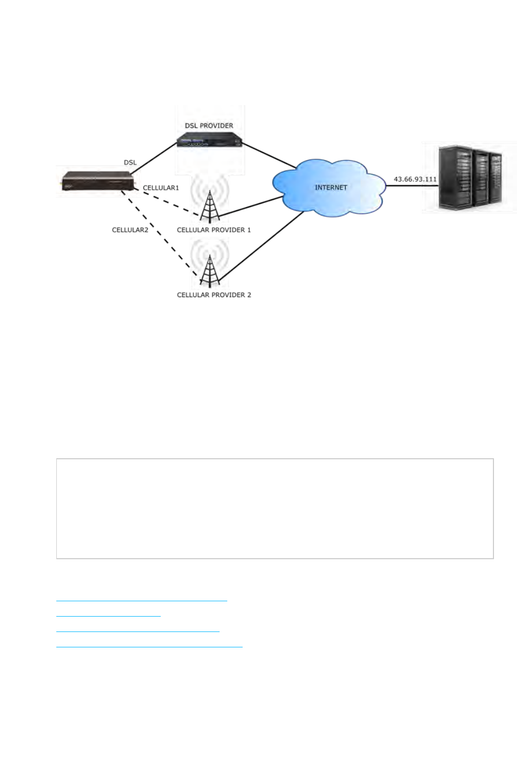
Example WAN failover: DSLto cellular
In this example, WAN, the dsl interface is the primary WAN. cellular1 and cellular2 interfaces serve
as backups to dsl.
IPprobing is configured over the DSL interface. A probe packet of size 256 bytes is sent every 10
seconds to the IP host 43.66.93.111. If no responses are received for 60 seconds, the TransPort LR
device brings the DSL interface down and starts using the wan2 (cellular1) interface.
If the TransPort LR device cannot get a connection on the cellular2 interface, it attempts to use the
wan3 (cellular2) interface. It attempts to switch back to the wan2 (cellular1) interface after 30
minutes (1800 seconds).
The TransPort LR device continues to send probes out of the DSL interface. If it receives probe
responses for 120 seconds, it reactivates the wan1 interface and starts using it again as the WAN
interface.
To achieve this WAN interface failover from DSLto the cellular interface, the WANfailover
configuration commands are:
wan 1 interface dsl
wan 1 probe-host 43.66.93.111
wan 1 probe-interval 10
wan 1 probe-size 256
wan 1 timeout 60
wan 1 activate-after 120
wan 2 interface cellular1
wan 2 try-after 1800
wan 3 interface cellular2
Related topics
Wide Area Networks (WANs) on page 52
WAN failover on page 53
Configure a WANinterface on page 54
Show WAN status and statistics on page 59

Wide Area Networks (WANs)
TransPort LR User Guide 59
Show WAN status and statistics
To show the status and statistics for a cellular interface, use the show wan on page 201 command.
For a description of the output fields, see the show wan on page 201 command.
Here is here is the show wan on page 201 command output when no WANs are configured:
digi.router> show wan
# WAN Interface Status IP Address
-----------------------------------
digi.router>
Here is the show wan on page 201 command output with eth2 and cellular1 configured as WAN
interfaces, where eth2 is upand cellular1 is down.
digi.router> show wan
# WAN Interface Status IP Address
-----------------------------------
2 eth2 Up 192.168.0.25
3 cellular1 Down
digi.router>
Here is a show wan on page 201 example with eth2 and cellular1 both up:
digi.router> show wan
# WAN Interface Status IP Address
-----------------------------------
2 eth2 Up 192.168.0.25
3 cellular1 Up 172.20.1.7
digi.router>
Related topics
Wide Area Networks (WANs) on page 52
WAN failover on page 53
Configure a WANinterface on page 54
Example WAN failover: DSLto cellular on page 57
Related commands
wan on page 213
show wan on page 201

Security
TransPort LR User Guide 60
Security
TransPort LR devices have several device security features. This section covers the configuring
security settings from the web interface and command line.
Security
TransPort LR User Guide 61
User management
User management involves configuring and managing TransPort LR device users, including their
authentication credentials and access permissions.
Related topics
Users and user access permissions on page 61
Configure a user on page 62
Related commands
user on page 212
Users and user access permissions
To manage TransPort LR devices via the command-line interface or web interface, users must log in
using a configured username and password.
This topic covers the TransPort LRuser model and access permissions for users.
Number of supported users
Up to 10 administrative users are supported. Each user has a unique name, password and access
level.
Default user
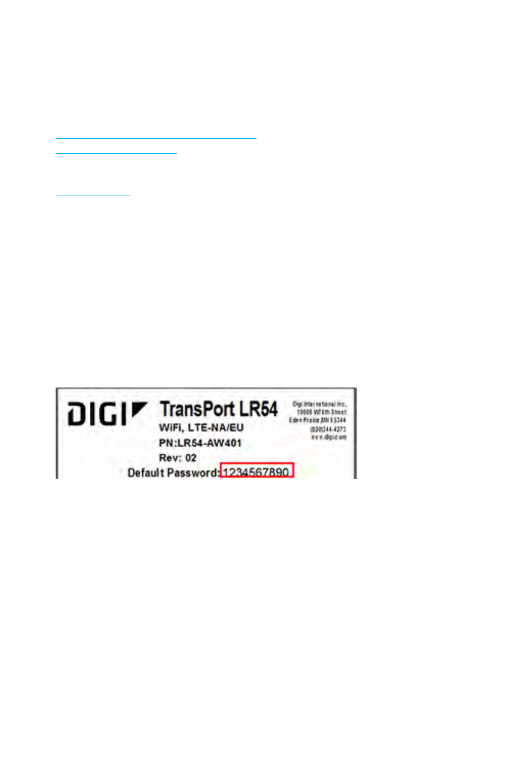
By default, TransPort LR devices have one user preconfigured. This default user is configured as user
1. Its default username is admin. Its default password is displayed on the label on the bottom of the
device, for example:
You can change this user 1 configuration to match your requirements.
User access permissions
TransPort LR devices support three access levels: super,read-write, and read-only. These access
levels determine the level of control users have over device features and their settings.

Security
TransPort LR User Guide 62
Access level Permissions allowed
super The user can manage all features on TransPort LR devices. Devices can
have multiple users with super access level.
A user with super access level is required to be present on a device, to
allow editing user access levels. If you or any other device user deletes
the only user with super access level, you must restore the default
user configuration by resetting the device to factory defaults.
read-write The user can manage all device features except security-related
features, such as configuring user access, configuring firewalls, clearing
logs, etc.
read-only The user can monitor device configuration and status, but cannot
change the configuration or status of the TransPort LR device.
Related topics
Configure a user on page 62
Delete a user on page 63
Reset the device to factory defaults on page 130
Related commands
user on page 212
Configure a user
To configure a user, you need to configure the following:
Required configuration items
nUsername.
nPassword. For security reasons, passwords are stored in hash form. There is no way get or
display passwords in clear-text form.
Additional configuration options
nSetting user access permissions. The access level for users defaults to super. To restrict the
access of this user to either read-write or read-only, you should configure the access level.
From the command line
The user on page 212 command configures users.
1. Configure the username. For example:
user 1 name joeuser

Security
TransPort LR User Guide 63
2. Configure the password. For example:
user 1 password omnivers1031
3. Optional: Configure the access level. For example:
user 1 access read-write
Related topics
Users and user access permissions on page 61
Delete a user on page 63
Related commands
user on page 212
Delete a user
To delete a user:
From the command line
Enter the following command:
user n name !
Configure the password. For example, to delete the user joeuser that was previously assigned to
user 1, enter:
user 1 name !
Related topics
Users and user access permissions on page 61
Configure a user on page 62
Related commands
user on page 212

Remote management
TransPort LR User Guide 71
Remote management
These topics cover using remote management facilities to manage TransPort LRdevices.

Remote management
TransPort LR User Guide 72
Remote Manager
Digi Remote Manager is a hosted remote configuration and management system that allows you to
remotely manager a large number of devices. Digi Remote Manager has a web-based interface from
which you can perform device operations, such as viewing and changing device configurations and
perform firmware updates.
The Digi Remote Manager servers also provide a data storage facility.
Using Digi Remote Manager requires setting up a Digi Remote Manager account. To set up a Digi
Remote Manager account and learn more about Digi Remote Manager, go to
http://www.digi.com/products/cloud/digi-remote-manager.
Configure Remote Manager
Delete this text and replace it with your own content.

Remote management
TransPort LR User Guide 73
Simple Network Management Protocol (SNMP)
Simple Network Management Protocol (SNMP) is a protocol for remotely managing and monitoring
network devices. Network administrators can use the SNMP architecture to manage nodes,
including servers, workstations, routers, switches, hubs, and other equipment on an IP network,
manage network performance, find and solve network problems, and plan for network growth.
Supported SNMP versions
Transport LR devices support the SNMP versions SNMPv1,SNMPv2c, and SNMPv3.
The device supports up to 10 SNMPv1/SNMPv2c communities. Each community can have read-only or
read-write access.
The device supports up to 10 SNMPv3 users. You can configure each user's access level as read-only
or read-write, and configure security settings on an individual-user basis.
Supported Management Information Bases (MIBs)
Transport LR devices support the following SNMP MIBs for managing the entities in a communication
network:
nStandard SNMP MIBs
nAn enterprise-specific MIB, specific to the LR54, named transport-lr54.mib. This MIB is
available for download from Digi Support.
Note SNMPv1 cannot be used with the Enterprise MIB, owing to the COUNTER64 types used in the
MIB.
Related topics
Configure SNMPv1 and SNMPv2 on page 73
Configure SNMPv3 on page 74
Related commands
snmp on page 204
snmp-community on page 205
snmp-user on page 206
Configure SNMPv1 and SNMPv2
Configuring SNMPv1 or SNMPv2c support involves configuring the following items:
nEnabling the desired SNMP version
nWhether to configure SNMPv1/v2c communities
nIf configuring SNMPv1/v2c communities, the community access level
From the command line
1. All SNMP versions are disabled by default. Enable support for SNMPv1 or SNMPv2c by
entering:
snmp v1 on
OR

Remote management
TransPort LR User Guide 74
snmp v2c on
2. If using SNMPv1/v2c communities, configure a name for each community. For example:
snmp-community 1 community public
3. The community access level defaults to read-only. To set the access level to read-write,
enter:
snmp-community 1 access read-write
Related topics
Simple Network Management Protocol (SNMP) on page 73
Configure SNMPv3 on page 74
Related commands
snmp on page 204
snmp-community on page 205
snmp-user on page 206
Configure SNMPv3
Configuring SNMPv3 support involves configuring the following items:
nEnabling SNMPv3.
nConfiguring the SNMPv3 users. Up to 10 SNMPv3 users can be configured.
nConfiguring SNMPv3 user authentication type and password, privacy type and password, and
user access level.
From the command line
1. All SNMP versions are disabled by default. To enable support for SNMPv3, enter:
snmp v3 on
2. For each SNMPv3 user, give the user a name of up to 32 characters:
snmp-user 1 user joe
3. Set the authentication type for the SNMPv3 user (none,md5, or sha1). To use privacy (DES or
AES), the authentication type be either md5 or sha1.
snmp-user 1 authentication sha1
4. Set the authentication password for the SNMPv3 user. The password length can be between
8 and 64 characters.
snmp-user 1 authentication-password authpassword

Remote management
TransPort LR User Guide 75
5. Set the privacy type for the SNMPv3 user (none,aes, or des):
snmp-user 1 authentication des
6. Set the privacy password for the SNMPv3 user. The password length can be between 8 and 64
characters.
snmp-user 1 privacy-password privpassword
7. Configure the access level for the SNMPv3 user.
snmp-user 1 access read-write
Related topics
Simple Network Management Protocol (SNMP) on page 73
Configure SNMPv3 on page 74
Related commands
snmp on page 204
snmp-community on page 205
snmp-user on page 206

Routing
TransPort LR User Guide 77
IP routing
The TransPort LRdevice uses IP routes to decide where to send a packet that it receives for a
remote network. The process for deciding on a route to send the packet is as follows:
1. The device examines the destination IP address in the IP packet, and looks through the IP
routing table to find a match for it.
2. If it finds a route for the destination, it forwards the IP packet to the configured IP gateway or
interface.
3. If it cannot find a route for the destination, it uses a default route.
4. If there are two or more routes to a destination, the device uses the route with the longest
mask.
5. If there are two or more routes to a destination with the same mask, the device will use the
route with the lowest metric.
Configuring and managing IProuting involves the following tasks:

Routing
TransPort LR User Guide 78
Configure general IP settings
Configuring general IPsettings is one of the building blocks of setting up IProuting.
Optional configuration settings
nThe IP hostname. This hostname identifies the TLR device on IP networks. It is an unqualified
hostname. The default setting for the device isLR54-%s which expands to LR54-<serial
number>.
nThe administrative distance settings for connected and static routes. Administrative distance
settings rank the type of routes, from the most to least preferred. When there are two or
more routes to the same destination and mask, the route with the lowest metric is used. By
default, routes to connected networks are preferred, with static routes being next. The
administrative distance for each route type is added to the route’s metric when it is added to
the routing table. Configuring the administrative distance of a particular route type can alter
the order of use for the routes. The two administrative distance settings are:
lAdministrative distance for connected network routes. The default value is 0.
lAdministrative distance for static routes. The default value is 1.
From the command line
1. Set the hostname.
ip hostname LR54-NewYork
2. Set the administrative distance for connected routes.
ip admin-conn 3
3. Set the administrative distance for static routes.
ip admin-static 5
Related topics
IP routing on page 77
Configure a static route on page 79
Show the IPv4 routing table on page 81
Delete a static route on page 82
Related commands
ip on page 161

Routing
TransPort LR User Guide 79
Configure a static route
A static route is a manually configured routing entry. Information about the route is manually
entered rather than obtained from dynamic routing traffic. TransPort LR devices supports up to 32
static routes. Will this be the same across all product models or will we need multiple statements for
multiple models?
Required configuration settings
nSetting the destination network and mask.
nSetting the gateway IP address for routes using LAN and WAN Ethernet interfaces. The
gateway IP address should be on the same subnet as the IP address of the LAN or WAN
Ethernet interface in use.
nSetting the interface name for routes using cellular and DSL interfaces.
Optional configuration settings
nSetting the metric for the route. The metric defines the order in which routes should be used
if there are two routes to the same destination. In such a case, the smaller metric is used.
From the command line
Example 1
To configure a static route to the 192.168.47.0/24 network using the lan1 interface, which has an IP
address of 192.168.1.1 and a gateway at IP address of 192.168.1.254:
1. Set the destination network and mask.
route 1 destination 192.168.47.0
route 1 mask 255.255.255.0
2. Set the gateway IPaddress.
route 1 gateway 192.168.1.254
Example 2
To configure a static route to the 44.1.0.0/16 network using the cellular1 interface:
1. Set the destination network and mask.
route 4 destination 44.1.0.0
route 4 mask 255.255.0.0
2. Set the interface.
route 4 interface cellular1
3. Optional: Set the metric.
route 4 metric 5

Routing
TransPort LR User Guide 80
Once the static route is configured, it should be shown in the IPv4 routing table.
Related topics
IP routing on page 77
Configure general IP settings on page 78
Show the IPv4 routing table on page 81
Delete a static route on page 82
Related commands
ip on page 161
route on page 175
show route on page 197

Routing
TransPort LR User Guide 81
Show the IPv4 routing table
To display the IPv4 routing table, use the show route on page 197 command.
digi.router> show route
Destination Gateway Metric Protocol Idx Interface Status
--------------------------------------------------------------------------------------
10.1.2.0/24 192.168.1.254 1 Static 1 lan1 UP
192.168.1.0/24 0.0.0.0 0 Connected lan1 UP
default 0.0.0.0 1 Connected eth1 UP
default 0.0.0.0 2 Connected cellular1 UP
digi.router>
Related topics
IP routing on page 77
Configure general IP settings on page 78
Configure a static route on page 79
Delete a static route on page 82
Related commands
ip on page 161
route on page 175
show route on page 197

Routing
TransPort LR User Guide 82
Delete a static route
To remove a static route from the routing table, clear the destination network configuration.
From the command line
Enter the route on page 175 command, specifying the interface number, the destination parameter
and !to revert the settings for the route destination. For example:
route 1 destination !
Related topics
IP routing on page 77
Configure general IP settings on page 78
Configure a static route on page 79
Show the IPv4 routing table on page 81
Related commands
ip on page 161
route on page 175
show route on page 197

Routing
TransPort LR User Guide 83
Virtual Private Networks (VPN)
Virtual Private Networks (VPNs) are used to securely connect two private networks together so that
devices can connect from one network to the other network using secure channels. These topics
cover the various network protocols involved in VPNs, and configuring VPNs from the web interface
and command line.

Routing
TransPort LR User Guide 84
IPsec
IPsec is a suite of protocols for creating a secure communication link, or IPsec tunnel, between a
host and a remote IP network or between two IP networks across a public network such as the
internet.
TransPort LR devices support to up 32 IPsec tunnels.
IPsec data protection
IPsec protects the data being sent across a public network by providing the following:
Data origin authentication
Authentication of data to validate the origin of data when it is received.
Data integrity
Authentication of data to ensure it has not been modified during transmission.
Data confidentiality
Encryption of data sent across the IPsec tunnel to ensure that an unauthorized device cannot
read the data.
Anti-Replay
Authentication of data to ensure an unauthorized device has not injected it into the IPsec tunnel.
IPsec modes
IPsec can run in two different modes: Tunnel and Transport.
Currently, TransPort LR devices support tunnel mode only.
Tunnel
The entire IP packet is encrypted and/or authenticated and then encapsulated as the payload in
a new IP packet.
Transport
Only the payload of the IP packet is encrypted and/or authenticated. The IP header is left
untouched. This mode has limitations when using an authentication header, because the IP
addresses in the IP header cannot be translated (for example, with Network Address Translation
(NAT), as it would invalidate the authentication hash value.
Internet Key Exchange (IKE) settings
IKE is a key management protocol is used by IPsec to negotiate the security associations (SAs) that
are used to create the secure IPsec tunnel.
SA negotiations are perfomed in two phases, known as phase 1 and phase 2.
Phase 1
In phase 1, IKE creates a secure authenticated communication channel between the device and the
peer (the remote device which is at the other end of the IPsec tunnel) using the configured pre-
shared key and the Diffie-Hellman key exchange. This creates the IKE SAs that are used to encrypt
further IKE communications.
There are two modes for the phase 1 negotiation: Main mode and Aggressive mode.
Main mode
Main mode is the default mode. It is slower that aggressive mode, but more secure, in that all
sensitive information sent between the device and its peer is encrypted.
Aggressive mode

Routing
TransPort LR User Guide 85
Aggressive mode is faster than main mode, but is not as secure as main mode, because the
device and its peer exchange their IDs and hash information in clear text instead of being
encrypted. Aggressive mode is usually used when one or both of the devices have a dynamic
external IP address.
Phase 2
In phase 2, IKE negotiates the SAs for IPsec. This creates two unidirectional SAs, one for each
direction. Once the phase 2 negotiation is complete, the IPsec tunnel should be fully functional.
There are two versions of IKE, IKEv1 and IKEv2. Currently the LR54 only supports IKEv1.
IPsec and IKE renegotiation
To reduce the chances of an IPsec tunnel being compromised, the IPsec SAs and IKE SA are
renegotiated at a regular interval. This results in different encryption keys being used in the IPsec
tunnel.
Related topics
Related commands
ipsec on page 162
ipsec-failover on page 166
show dsl on page 182
Configure an IPSec tunnel
Configuring an IPsec tunnel with a remote device involves configuring the following items:
Required configuration items
IPsec tunnel configuration settings
nEnabling the IPsec tunnel.
nThe IP address or name of the remote device, also known as the peer, at the other end of the
IPsec tunnel.
nThe local and remote IDs.
nThe local and remote IP networks.
nThe authentication protocol to use. This setting must match the authentication protocol
configured on the remote device. The authentication options are:
lSHA1
lSHA256
The default value is SHA1.
nThe encryption protocol to use. This has to match the encryption protocol configured on the
remote device. The encryption options are:

Routing
TransPort LR User Guide 86
lAES – 128 bits
lAES – 192 bits
lAES – 256 bits
The default value is AES – 128 bits.
nThe Encapsulating Security Payload (ESP) Diffie-Hellman group for the IPsec tunnel.This
setting must match the Diffie-Hellman group configured on the remote device. The Diffie-
Hellman group options are:
lNone
lGroup 5 (1536 bits)
lGroup 14 (2048 bits)
lGroup 15 (3072 bits)
lGroup 16 (4096 bits)
lGroup 17 (6144 bits)
lGroup 18 (8192 bits)
The default value is Group14.
The larger the number of bits, the more secure the IPsec tunnel. However, a larger bit length
requires more computing power, which can slow down the tunnel negotiation and
performance.
nThe shared key the device and the remote device use to authenticate each other.
IKE configuration settings
nThe IKE mode.
lMain
lAggressive
The default option is Main.
nThe IKE authentication protocols to use for the IPsec tunnel negotiation. The authentication
options are:
lSHA1
lSHA256
The default is SHA1.
You can select more than one authentication protocol. IKE negotiates with the remote device
which to use. This setting does not need to match the IKE authentication protocols configured
on the remote device, but at least one of the authentication protocols must be configured on
the remote device.
nThe IKE encryption protocols to use for the IPsec tunnel negotiation. The encryption options
are:
lAES – 128 bits
lAES – 192 bits
lAES – 256 bits

Routing
TransPort LR User Guide 87
The default is AES – 128 bits.
You can select more than one encryption protocol. IKE negotiates with the remote device
which encryption protocol to use. This setting does not need to match the IKE encryption
protocols configured on the remote device, but at least one of the encryption protocols must
be configured on the remote device.
nThe IKE Diffie-Hellman groups to use for the IPsec tunnel negotiation. The Diffie-Hellman
group options.
lGroup 5 (1536 bits)
lGroup 14 (2048 bits)
lGroup 15 (3072 bits)
lGroup 16 (4096 bits)
lGroup 17 (6144 bits)
lGroup 18 (8192 bits)
The default value is Group14.
You can select more than one Diffie-Hellman group. IKE negotiates with the remote device
which group to use. This setting does not need to match the IKE Diffie-Hellman groups
configured on the remote device, but at least of the Diffie-Hellman groups must be configured
on the remote device.
Additional configuration items
The following additional configuration settings are not typically configured to get an IPsec tunnel
working, but can be configured as needed:
Tunnel and key renegotiating
nThe lifetime of the IPsec tunnel before it is renegotiated. This defaults to 1 hour (3600
seconds), and does not need to match the setting on the remote device.
nThe number of bytes, also known as lifebytes, sent on the IPsec tunnel before it is
renegotiated. By default, this setting is disabled, but can be configured up to 4 GB. This
setting does not need to match the setting on the remote device.
nThe IKE lifetime before the keys are renegotiated. This defaults to 4800 seconds and does
not need to match the IKE lifetime configured on the remote device.
nThe amount of time before the IPsec lifetime expires, the renegotiation should start. This
defaults to 540 seconds and does not need to match the setting on the remote device.
nThe number of bytes before the IPsec lifebytes limit is reached before the key is is
renegotiated. By default, this is set to 0 and does not need to match the setting on the
remote device.
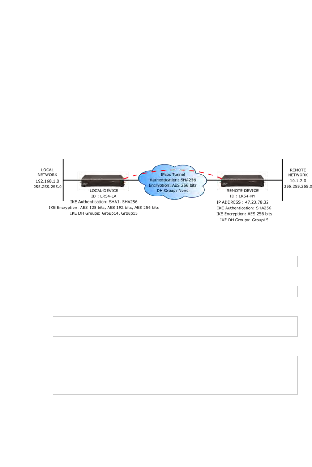
Routing
TransPort LR User Guide 88
nA randomizing factor for the number of seconds or bytes margin before the IPsec tunnel is
renegotiated. This defaults to 100% and does not need to match the setting on the remote
device. This setting would be used if the device has a number of IPsec tunnels configured to
ensure that the IPsec tunnels are not renegotiated at the same time which could put
excessive load on the device.
Other configuration items
nA description for the IPsec tunnel.
nThe number of tries IKE will attempt to negotiate the IPsec tunnel with the remote device
before giving up.
Example IPsec tunnel
Suppose you are configuring the following IPsec tunnel:
From the command line
1. Enable the IPsec tunnel.
ipsec 1 state on
2. Enter the IP address or name of the remote device.
ipsec 1 peer 47.23.78.32
3. Enter the local and remote IDs.
ipsec 1 local-id LR54-LA
ipsec 1 remote-id LR54-NY
4. Enter the local and remote IP networks.
ipsec 1 local-network 192.168.1.0
ipsec 1 local-mask 255.255.255.0
ipsec 1 remote-network 10.1.2.0
ipsec 1 remote-mask 255.255.255.0
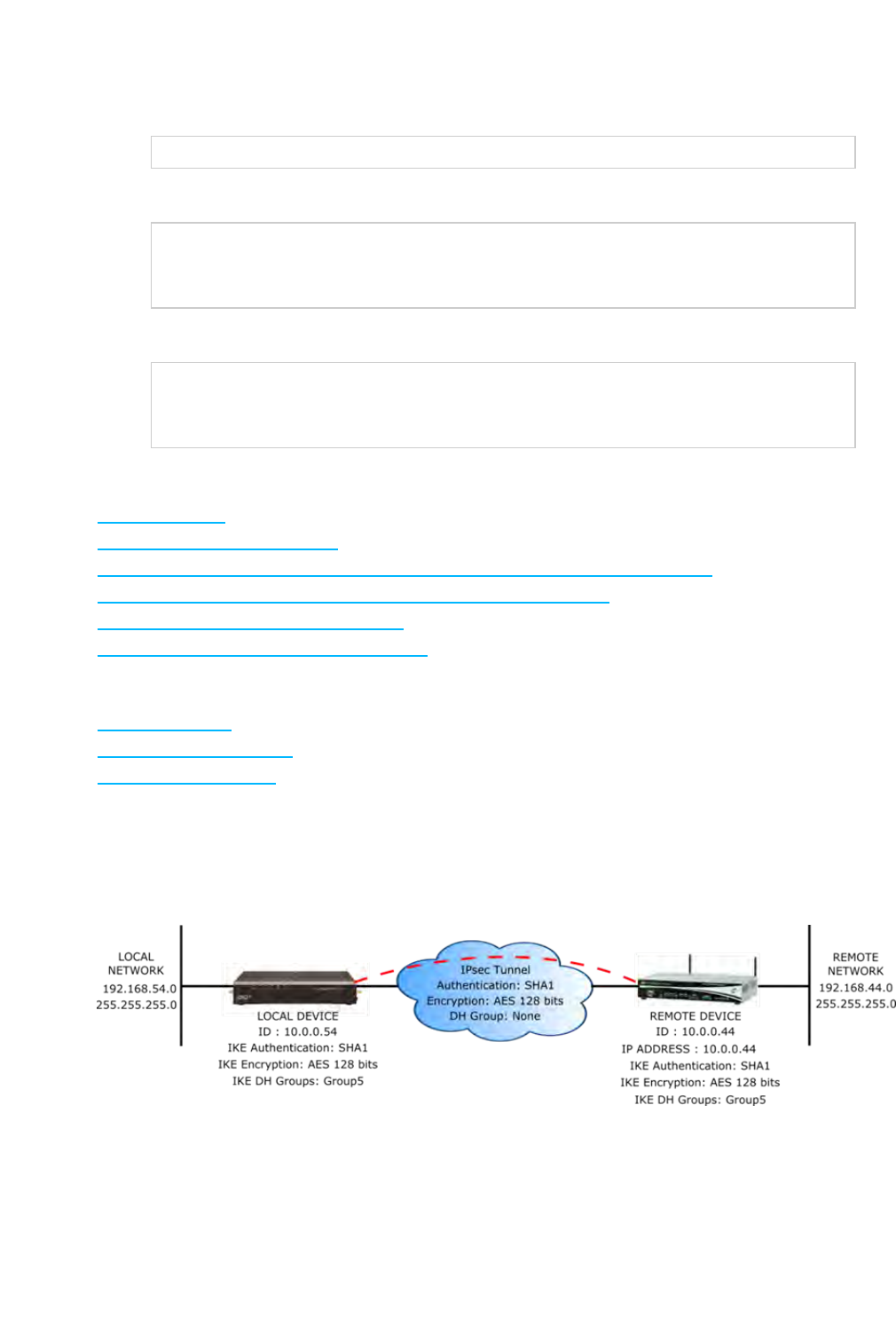
Routing
TransPort LR User Guide 89
5. Enter the pre-shared key.
ipsec 1 psk “secret-psk”
6. Enter the IPsec authentication, encryption, and Diffie-Hellman settings.
ipsec 1 esp-authentication sha256
ipsec 1 esp-encryption aes256
ipsec 1 esp-diffie-hellman none
7. Enter the IKE authentication, encryption, and Diffie-Hellman settings.
ipsec 1 ike-authentication sha1,sha256
ipsec 1 ike-encryption aes128,aes192,aes256
ipsec 1 ike-diffie-hellman group14,group15
Related topics
IPsec on page 84
IPSec tunnel failover on page 91
Example: IPsec tunnel between a TransPort LR54 and TransPort WR44 on page 89
Example: IPSec tunnel between a TransPort LR54 and a Cisco router
Debug an IPsec configuration on page 92
Show IPsec status and statistics on page 92
Related commands
ipsec on page 162
ipsec-failover on page 166
show ipsec on page 191
Example: IPsec tunnel between a TransPort LR54 and TransPort WR44
Following an example IPsec configuration between an TransPort LR54 and a TransPort WR44.
The configuration settings for both devices are as follows:

Routing
TransPort LR User Guide 90
TransPort LR54 configuration TransPort WR44 configuration
digi.router> lan 1
state on
description IPsec local net
mtu 1500
interfaces eth2,eth3,eth4
ip-address 192.168.54.1
mask 255.255.255.0
dns1
dns2
dhcp-client off
digi.router> lan 2
state on
description Link to WR44
mtu 1500
interfaces eth1
ip-address 10.0.0.54
mask 255.255.255.0
dns1
dns2
dhcp-client off
digi.router> ipsec 1
state on
description Tunnel to WR44
peer 10.0.0.44
local-network 192.168.54.0
local-mask 255.255.255.0
remote-network 192.168.44.0
remote-mask 255.255.255.0
esp-authentication sha1
esp-encryption aes128
esp-diffie-hellman none
auth-by psk
psk <configured>
local-id 10.0.0.54
remote-id 10.0.0.44
lifetime 3600
lifebytes 0
margintime 540
marginbytes 0
random 100
ike 1
ike-mode aggressive
ike-encryption aes128
ike-authentication sha1
ike-diffie-hellman group5
ike-lifetime 3600
ike-tries 3
dpddelay 30
dpdtimeout 150
# Link to TransPort LR54
eth 0 IPaddr "10.0.0.44"
eth 0 ipsec 1
# IPsec local network
eth 1 IPaddr "192.168.44.1"
# Route to remote network
route 0 IPaddr "192.168.54.0"
route 0 ll_ent "eth"
# IPsec tunnel configuration
eroute 0 peerip "10.0.0.54"
eroute 0 peerid "10.0.0.54"
eroute 0 ourid "10.0.0.44"
eroute 0 ouridtype 3
eroute 0 locip "192.168.44.0"
eroute 0 locmsk
"255.255.255.0"
eroute 0 remip "192.168.54.0"
eroute 0 remmsk
"255.255.255.0"
eroute 0 ESPauth "sha1"
eroute 0 ESPenc "aes"
eroute 0 authmeth "preshared"
eroute 0 autosa 2
# IKE configuration
ike 0 encalg "aes"
ike 0 keybits 128
ike 0 authalg "sha1"
ike 0 ltime 30000
ike 0 aggressive ON
ike 0 ikegroup 5
# Remote ID / Password
user 1 name "10.0.0.54"
user 1 epassword "MDp6Vko=

Routing
TransPort LR User Guide 93
Rekeying In : 68 minutes
AH Cipher Suite : Not Used
ESP Cipher Suite : aes128, sha1
Renegotiating In : 42 minutes
Outbound ESP SA : 0x9E1325F2
Inbound ESP SA : 0x757935D6
Bytes In : 0
Bytes Out : 0
digi.router>
Related topics
IPsec on page 84
IPSec tunnel failover on page 91
Configure an IPSec tunnel on page 85
Example: IPsec tunnel between a TransPort LR54 and TransPort WR44 on page 89
Example: IPSec tunnel between a TransPort LR54 and a Cisco router
Debug an IPsec configuration on page 92
Related commands
ipsec on page 162
ipsec-failover on page 166
show dsl on page 182

System administration and management
TransPort LR User Guide 96
Set system date and time
Having an accurate date and time set on your device is important for a number of reasons, including
validating certificates and having accurate timestamps on events in the event log.
Methods for setting system date and time
There are two methods for setting system date and time:
nUsing the Simple Network Time Protocol (SNTP). SNTP continually polls an external NTPtime
server on either a private company network or the internet at a configured interval rate.
SNTP usually provides an accuracy of less than a second.
nSetting the date and time manually.
Set the date and time using SNTP
Required configuration items
nEnable SNTP.
Additional configuration options
nThe SNTP server. By default, SNTP is configured to use Digi’s SNTPserver,
time.devicecloud.com.
nThe SNTPupdate interval. This is the interval at which the TLR device checks the SNTP server
for date and time. By default, SNTP is checked every hour. At bootup, the device attempts to
send an update message to the configured SNTP server every 15 seconds until it receives a
response. Once it receives a response, it reverts to the configured update interval.
From the command line
To set the date and time using SNTP, use the sntp on page 207 command.
1. Enable SNTP.
sntp state on
2. Optional: Set the SNTP server. For example, to set the server to time.digi.com:
sntp server time.digi.com
3. Optional: Set the SNTPupdate interval.
sntp update-interval 10
Set the date and time manually
From the command line
To set the date and time manually, use the date on page 149 command. The date on page 149
command specifies the time in HH:MM:SS format, where seconds are optional, followed by the date,
in DD:MM:YYYY format.
For example, to manually set the time and date to 14:55:00 on May 3, 2016, enter:


System administration and management
TransPort LR User Guide 98
Show system date and time
From the command line
To display the current system date and time, use the date on page 149 command.
digi.router> date
system time: 14:55:06, 03 May 2016
digi.router>
Related topics
Set system date and time on page 96
Related commands
date on page 149
sntp on page 207


System administration and management
TransPort LR User Guide 107
Use multiple configuration files to test the configuration on remote devices
You can use multiple configuration files, along with the autorun on page 141 command, to test a new
configuration on a remote device that might result in the remote device going offline, in which case
the device cannot be remotely accessed.
To test the configuration on a remote device, create a new configuration file with desired
configuration changes to test. In addition to the desired configuration changes, the file should
contain two autorun on page 141 commands:
nThe first autorun on page 141 command automatically reverts the device to use the original
configuration file.
nThe second autorun on page 141 command schedules a reboot after a period of time.
Example test configuration file
For example, suppose you creates a new test configuration file named test.cfg
This test.cfg file changes the cellular 1 apn parameter, and executes two autorun on page 141
commands to automatically revert the device back to use the config.da0 configuration file and to
reboot in 5minutes. It then saves the configuration to test.cfg and reboots the device.
update config test.cfg
cellular 1 apn new-apn-to-test
autorun 1 command “update config config.da0”
autorun 2 command “reboot in 5”
save config
reboot
If the TransPort LR device does not come back online, the device automatically reverts to the old
(working) configuration file, config.da0, and reboots after 5minutes.
If the device comes back online after being rebooted with the configuration (that is, the device
connected with the new cellular APN), you can cancel the scheduled reboot using the reboot cancel
command.
reboot cancel
Using the copy on page 147 and update on page 211 commands, you can then copy the configuration
file to the final configuration file, and change the configuration file name.
copy test.cfg config.da0
update config config.da0
Related topics
Managing configuration files on page 102
Save configuration settings to a file on page 137
Switch between configuration files on page 137
Related commands
autorun on page 141
copy on page 147
reboot on page 172
save on page 176

TransPort LR User Guide 115
Make a directory
To make a new directory in the TLR filesystem, use the mkdir on page 168 command, specifying the
name of the directory.
For example:
digi.router> mkdir test
digi.router> dir
File Size Last Modified
-------------------------------------------------------
test Directory
config.da0 763 Sun Mar 5 12:36:20
config.fac 186 Mon Feb 21 03:00:17
Remaining User Space: 102,457,344 bytes
digi.router>

TransPort LR User Guide 116
Display directory contents
To display directory contents, use the dir on page 152 command. For example:
digi.router> dir
File Size Last Modified
---------------------------------------------------------
test Directory
config.da0 763 Sun Mar 5 12:36:20
config.fac 186 Mon Feb 21 03:00:17
Remaining User Space: 102,457,344 bytes
digi.router>

TransPort LR User Guide 117
Change the current directory
To change the current directory, use the cd on page 142 command, specifying the directory name.
For example:
digi.router> dir
File Size Last Modified
---------------------------------------------------------
test Directory
config.da0 763 Sun Mar 5 12:36:20
config.fac 186 Mon Feb 21 03:00:17
Remaining User Space: 102,457,344 bytes
digi.router>
digi.router> cd test
digi.router> dir
File Size Last Modified
---------------------------------------------------------
Remaining User Space: 102,457,344 bytes
digi.router>

TransPort LR User Guide 118
Remove a directory
To remove a directory:
1. Make sure the directory is empty.
2. Use the rmdir on page 174 command, specifying the name of the directory to remove.
For example:
digi.router> dir
File Size Last Modified
---------------------------------------------------------
test Directory
config.da0 763 Sun Mar 5 12:36:20
config.fac 186 Mon Feb 21 03:00:17
Remaining User Space: 102,457,344 bytes
digi.router>
digi.router> rmdir test
Directory test is not empty
ERROR
digi.router>
digi.router> dir test
File Size Last Modified
---------------------------------------------------------
config.tst 186 Wed Apr 5 07:10:41
Remaining User Space: 102,457,344 bytes
digi.router>
digi.router> del test/config.tst
digi.router>
digi.router> rmdir test
digi.router>
digi.router> dir
File Size Last Modified
---------------------------------------------------------
config.da0 763 Sun Mar 5 12:36:20
config.fac 186 Mon Feb 21 03:00:17
Remaining User Space: 102,457,344 bytes

Display file contents
TransPort LR User Guide 120
Display file contents
To display the contents of a file, use the more on page 169 command, specifying the name of the file.
For example:
digi.router> more config.da0
# Last updated by username on Thu Nov 19 14:26:02 2015
eth 1 ip-address "192.168.1.1"
cellular 1 apn "mobile.o2.co.uk"
cellular 1 state "on"
user 1 name "username"
user 1 password "$1$4WdqUHrv$K.aB78KILuxVpesZtyveG/"
digi.router>

Copy a file
TransPort LR User Guide 121
Copy a file
To copy a file, use the copy on page 147 command, specifying the existing file name, followed by the
name of the new copy.
For example, to copy file config.da0 to a file in the main directory named backup.da0, and then to a
file named test.cfg in the test directory, enter the following:
digi.router>
digi.router> dir
File Size Last Modified
---------------------------------------------------------
test Directory
config.da0 763 Sun Mar 5 12:36:20
config.fac 186 Mon Feb 21 03:00:17
Remaining User Space: 102,457,344 bytes
digi.router>
digi.router>
digi.router> copy config.da0 backup.da0
digi.router>
digi.router> dir
File Size Last Modified
---------------------------------------------------------
test Directory
config.da0 763 Sun Mar 5 12:36:20
config.fac 186 Mon Feb 21 03:00:17
backup.da0 763 Wed Apr 5 07:22:29
Remaining User Space: 102,457,344 bytes
digi.router>
digi.router>digi.router> copy config.da0 test/test.cfg
digi.router>
digi.router> dir test
File Size Last Modified
--------------------------------------------------------
test.cfg 763 Wed Apr 5 07:24:45
Remaining User Space: 102,457,344 bytes
digi.router>

Rename a file
TransPort LR User Guide 122
Rename a file
To rename a file, use the rename on page 173 command, specifying the existing name and the new
name.
For example:
digi.router> dir
File Size Last Modified
---------------------------------------------------------
test Directory
config.da0 763 Sun Mar 5 12:36:20
config.fac 186 Mon Feb 21 03:00:17
backup.da0 763 Wed Apr 5 07:22:29
Remaining User Space: 102,457,344 bytes
digi.router>
digi.router> rename backup.da0 test.da0
digi.router>
digi.router> dir
File Size Last Modified
---------------------------------------------------------
test Directory
test.da0 763 Wed Apr 5 07:22:29
config.da0 763 Sun Mar 5 12:36:20
config.fac 186 Mon Feb 21 03:00:17
Remaining User Space: 102,453,248 bytes
digi.router>

Delete a file
TransPort LR User Guide 123
Delete a file
To delete a file, use the del on page 150 command, specifying the filename to delete.
For example, to delete a file named test.cfg in the test directory, enter the following:
digi.router>
digi.router> dir
File Size Last Modified
---------------------------------------------------------
test Directory
test.da0 763 Wed Apr 5 07:22:29
config.da0 763 Sun Mar 5 12:36:20
config.fac 186 Mon Feb 21 03:00:17
Remaining User Space: 102,453,248 bytes
digi.router>
digi.router> del test.da0
digi.router>
digi.router> dir test
File Size Last Modified
---------------------------------------------------------
test.cfg 763 Wed Apr 5 07:24:45
Remaining User Space: 102,453,248 bytes
digi.router>
digi.router> del test/test.cfg
digi.router> dir test
File Size Last Modified
---------------------------------------------------------
Remaining User Space: 102,449,152 bytes
digi.router>

Upload and download files
TransPort LR User Guide 124
Upload and download files
You can download and upload files from and to a TLR device, using utilities such as Secure Copy (SCP),
SSH File Transfer Protocol (SFTP), or an SFTP application such as FileZilla.
Upload files using SCP
To upload a file to a TLRdevice using SCP, the syntax is as follows:
scp
filename
username@
ip_address
:filename
This example uploads a file named script.py to TLRdevice 192.168.1.1:
$ scp script.py john@192.168.1.1:script.py
Password:
script.py 100%
3728 0.3KB/s 00:00
Download files using SCP
To download a file from a TLRdevice using SCP, the syntax is as follows:
scp username@
ip_address
:
filename
filename
This example downloads a file named config.da0 from TLR device 192.168.1.1 using the username
john to the local directory:
$ scp john@192.168.1.1:config.da0 config.da0
Password:
config.da0 100%
254 0.3KB/s 00:00
Upload files using SFTP
This example uploads a file named lr54-1.0.2.10.bin to TLR device 192.168.1.1 using the username
john:
$ sftp john@192.168.1.1
Password:
Connected to 192.168.1.1
sftp> put lr54-1.0.2.10.bin
Uploading lr54-1.0.2.10.bin to lr54-1.0.2.10.bin
lr54-1.0.2.10.bin 100%
24M 830.4KB/s 00:00
sftp> exit
$
Download files using SFTP
This example downloads a file named config.da0 from TLR device 192.168.1.1 using the username
john to the local directory:
$ sftp john@192.168.1.1
Password:
Connected to 192.168.1.1
sftp> get config.da0
Fetching config.da0 to config.da0

Upload and download files
TransPort LR User Guide 125
config.da0 100%
254 0.3KB/s 00:00
sftp> exit
$

TransPort LR User Guide 133
Command reference
These topics describe the command-line interface for TransPort LR devices and the commands
entered through the command-line interface.

Command-line interface basics
TransPort LR User Guide 136
digi.router> dsl mode ?
Syntax : dsl 1 mode <value>
Description : DSL line mode
Current Value : auto
Valid Values : auto, adsl2-plus, adsl2, gdmt, glite
Default value : auto
digi.router> dsl mode
Revert command elements using the ! character
Entering !reverts an individual command element to its factory default. For example, to revert the
previous setting of interfaces on the lan command, enter:
lan 1 interfaces !
Auto-complete commands and parameters
When entering a command and parameter, pressing the Tab key causes the command-line interface
to auto-complete as much of the command and parameter as possible.
Auto-complete applies to these command elements only :
nCommand names. For example, entering cell<Tab> auto-completes the command as cellular
nParameter names. For example:
lping int<Tab> auto-completes the parameter as interface
lsystem loc<Tab>auto-completes the parameter as location.
nParameter values, where the value is one of an enumeration or an on|off type; for example,
eth 1 duplex auto|full|half
Auto-complete does not function for:
nParameter values that are string types
nInteger values
nFile names
nSelect parameters passed to commands that perform an action
Enter configuration commands
Configuration commands configure settings for various device features. These commands have the
following format:
<command> <instance> <parameter> <value>
Where <instance> is the index number associated with the feature. For example, this command
configures the eth1 Ethernet interface:
eth 1 ip-address 10.1.2.3
For commands with only one instance, you do not need to enter the instance; for example:
system timeout 100

Command-line interface basics
TransPort LR User Guide 138
CPU : 3% (min 1%, max 70%, avg 3%)
Temperature : Not available
Description :
Location :
Contact :
digi.router>
Change the configuration file name
1. Change the name of the configuration file to be used at boot-up and when the configuration is
saved.
update config <filename>
2. If the new configuration file does not exist, enter the save on page 176 command to create
and save the configuration file.
save config
Related topics
Managing configuration files on page 102
Save configuration settings to a file on page 137
Use multiple configuration files to test the configuration on remote devices on page 107
Related commands
save on page 176
show system on page 199
Display status and statistics using "show" commands
show commands display status and statistics for various features. For example:
nshow config on page 181 displays all the current configuration settings for the device. This is a
particularly useful during initial device startup after running the Getting Started Wizard, or
when troubleshooting the device.
nshow system on page 199 displays system information and statistics for the device, including
CPU usage.
nshow eth on page 186 displays status and statistics for specific or all Ethernet interfaces.
nshow dsl on page 182 displays status and statistics for the DSLinterface.
nshow cellular on page 178 displays status and statistics for specific or all cellular interfaces.
Enter file management commands
There are commands for managing files in the device's file system, such as copy,del,mkdr,rename,
rmdir.
For more information, see About the TLRfile system.

Command descriptions
TransPort LR User Guide 140
Command descriptions
Following are the TLR Family command-line interface commands. Commands are organized by
command type, in alphabetical order.

Command descriptions
TransPort LR User Guide 141
autorun
Configures commands to be automatically run at boot-up. Auto-run commands can be used for tasks
such as starting a Python program, switching configuration files, or scheduling a reboot. You can
configure up to 10 auto-run commands.
Syntax
autorun <1 - 10> <parameter> <value>
Parameters
command
Command to run.
Accepted value is any string up to 100 characters.
Examples
nautorun 1 command \"python script.py\"
Automatically run a Python program.

Command descriptions
TransPort LR User Guide 142
cd
Changes the current directory.
Syntax
cd [dir]
Parameters
dir
When a directory name is specified, 'cd' changes the current directory to it.

Command descriptions
TransPort LR User Guide 143
cellular
Configures a cellular interface.
Syntax
cellular <1 - 2> <parameter> <value>
Parameters
state
Enables or disables the cellular interface, or enables it as an on-demand interface. The 'on-demand'
setting allows configuring the cellular interface as an on-demand interface. An on-demand interface
is brought up as needed if a higher priority goes down.
Accepted values can be one of off, on or on-demand. The default value is off.
description
A description of the cellular interface.
Accepted value is any string up to 63 characters.
apn
The Access Point Name (APN) for the cellular interface.
Accepted value is any string up to 63 characters.
apn-username
The username for the APN.
Accepted value is any string up to 63 characters.
apn-password
The password for the APN.
This element is available to all users.
Accepted value is any string up to 128 characters.
preferred-mode
The preferred cellular mode for the cellular interface.
Accepted values can be one of auto, 4g, 3g or 2g. The default value is auto.
connection-attempts
The number of attempts to establish a cellular connection. After this number of attempts, the cellular
module is power cycled, and the device attmpts to make a cellular connection again.
Accepted value is any integer from 10 to 500. The default value is 20.
Examples
ncellular 1 state on
Enable the Cellular 1 interface.

Command descriptions
TransPort LR User Guide 144
ncellular 1 state off
Disable the Cellular 1 interface.
ncellular 1 state on-demand
Disable Cellular 1 interface until the failover task brings it up.
ncellular 2 apn broadband
Set the SIM slot 2 APN to 'broadband.'
ncellular 1 username my-username
Set the SIM slot 1 username to 'my-username.'
ncellular 1 password my-password
Set the SIM slot 1 password to 'my-password.'

Command descriptions
TransPort LR User Guide 145
clear
Clears system status and statistics, such as the event log, firewall counters, etc.
This command is available to super users only.
Syntax
clear firewall | log
Parameters
firewall
Clears firewall counters.
log
Clears the event log.
Examples
nclear firewall
Clear the packet and byte counters in all firewall rules.
nclear log
Clear the event log and leaves an entry in the log after clearing.

Command descriptions
TransPort LR User Guide 146
cloud
Configures Digi Remote Manager settings.
Syntax
cloud <parameter> <value>
Parameters
state
Enables or disables Digi Remote Manager.
Value is either on or off. The default value is off.
server
The name of the Digi Remote Manager server.
Value should be a fully qualified domain name. The default value is my.devicecloud.com.
reconnect
The time, in seconds, between the device's attempts to connect to Digi Remote Manager.
Accepted value is any integer from 0 to 3600. The default value is 30.
keepalive
The interval, in seconds, used to contact the server to validate connectivity over a non-cellular
interface.
Accepted value is any integer from 10 to 7200. The default value is 60.
keepalive-cellular
The interval, in seconds, used to contact the server to validate connectivity over a cellular interface.
Accepted value is any integer from 10 to 7200. The default value is 290.
keepalive-count
Number of keepalives missed before the device disconnects from Remote Manager.
Accepted value is any integer from 0 to 10. The default value is 3.

Command descriptions
TransPort LR User Guide 147
copy
Copies a file.
This command is available to all users.
Syntax
copy source dest
Parameters
source
The source file to be copied to the location specified by 'dest.'
dest
The destination file, or file to which the source file is copied.

Command descriptions
TransPort LR User Guide 148
cpu
Show CPU usage
Syntax
cpu
Parameters

Command descriptions
TransPort LR User Guide 149
date
Manually sets and displays the system date and time.
Syntax
date [HH:MM:SS [DD:MM:YYYY]]
Parameters
time
System time, specified in the 24-hour format HH:MM:SS.
date
System date, specified in the format DD:MM:YYYY.
Examples
ndate 14:55:00 03:05:2016
Set the system date and time to 14:55:00 on May 3, 2016.

Command descriptions
TransPort LR User Guide 150
del
Deletes a file.
This command is available to all users.
Syntax
del file
Parameters
file
The file to be deleted.

Command descriptions
TransPort LR User Guide 151
dhcp-server
Configures Dynamic Host Configuration Protocol (DHCP) server settings.
Syntax
dhcp-server <1 - 10> <parameter> <value>
Parameters
state
Enables or disables this DHCP server.
Value is either on or off. The default value is off.
ip-address-start
The first IP address in the pool of addresses to assign.
Value should be an IPv4 address.
ip-address-end
The last IP address in the pool of addresses to assign.
Value should be an IPv4 address.
mask
The IP network mask given to clients.
Value should be an IPv4 address.
gateway
The IP gateway address given to clients.
Value should be an IPv4 address.
dns1
Preferred DNS server address given to clients.
Value should be an IPv4 address.
dns2
Alternate DNS server address given to clients.
Value should be an IPv4 address.
lease-time
The length, in minutes, of the leases issued by this DHCP server.
Accepted value is any integer from 2 to 10080. The default value is 1440.

Command descriptions
TransPort LR User Guide 152
dir
Displays the contents of the current directory.
Syntax
dir [file]
Parameters
file
Lists information about the file (by default, the current directory).

Command descriptions
TransPort LR User Guide 153
dsl
Configures the DSL interface and account information.
This group is only supported in LR54, LR54W, LR54D and LR54DWC1 products.
Syntax
dsl <parameter> <value>
Parameters
state
Enables or disables the DSL interface, or enables it as an on-demand interface. The 'on-demand'
setting allows configuring the DSL interface as an on-demand interface. An on-demand interface is
brought up as needed if a higher priority goes down.
Accepted values can be one of off, on or on-demand. The default value is off.
description
Description of the DSL interface.
Accepted value is any string up to 63 characters.
mode
DSL line mode. The default, 'auto,' trains the DSL interface to the best available (highest
performance) mode offered by the DSLAM.
Accepted values can be one of auto, adsl2-plus, adsl2, gdmt or glite. The default value is auto.
vpi
Virtual Path Identifier (VPI) for the DSL interface.
Accepted value is any integer from 0 to 255. The default value is 0.
vci
Virtual Circuit Identifier (VCI) for the DSL interface.
Accepted value is any integer from 17 to 65535. The default value is 38.
encapsulation
Data encapsulation to use on the DSL interface.
Accepted values can be one of pppoa-vcmux, pppoa-llc, pppoe-vcmux or pppoe-llc. The default value is
pppoa-vcmux.
ppp-username
PPP username for this DSL interface.
Accepted value is any string up to 63 characters.
ppp-password
PPP password for the DSL interface.
This element is available to all users.
Accepted value is any string up to 128 characters.

Command descriptions
TransPort LR User Guide 154
mtu
Maximum Transmission Unit (MTU) for this DSL interface.
Accepted value is any integer from 128 to 1500. The default value is 1500.
delay-up
Delays the DSL interface from coming up for this number of seconds. This delay allows the DSL
provider network to propagate network changes after the device has connected to the network, and
before packets can be sent and received. This delay prevents the device from assuming the network
is fully operational before it actually is fully operational, which could in turn cause problems with
other features, such as interface failover. During this delay, the DSL??LED flashes, to indicate the
interface is not fully up. Because characteristics can differ among provider networks, use of this
parameter is provider-specific.
Accepted value is any integer from 0 to 60. The default value is 0.
Examples
ndsl vpi 0
Set the DSL Virtual Path Identifier to 0.
ndsl vci 38
Set the DSL Virtual Channel Identifier to 38.
ndsl encapsulation pppoa-vcmux
Set the DSL encapsulation type to 'PPPoA, VC-Mux.'
ndsl ppp-username my-username
Set the DSL account login username to 'my-username.'
ndsl ppp-password my-password
Set the DSL account login password to 'my-password.'
ndsl mode auto
Allow the DSL interface to train to any available line mode.
ndsl mode gdmt
Force the DSL interface to train only in G.dmt mode, or not at all.
ndsl state on
Enable DSL interface.

Command descriptions
TransPort LR User Guide 155
ndsl state off
Disable DSL interface.
ndsl state on-demand
Disable DSL interface until the failover task brings it up.

Command descriptions
TransPort LR User Guide 156
eth
Configures an Ethernet interface.
Syntax
eth <1 - 4> <parameter> <value>
Parameters
state
Enables or disables the Ethernet interface, or enables it as an on-demand interface. The 'on-demand'
setting allows configuring the Ethernet interface as an on-demand interface. An on-demand interface
is brought up as needed if a higher priority goes down.
Accepted values can be one of off, on or on-demand. The default value is on.
description
A description of the Ethernet interface.
Accepted value is any string up to 63 characters.
duplex
The duplex mode the device uses to communicate on the Ethernet network. The keyword 'auto'
causes the device to sense the mode used on the network and adjust automatically.
Accepted values can be one of auto, full or half. The default value is auto.
speed
Transmission speed, in Mbps, the device uses on the Ethernet network. The keyword 'auto' causes
the device to sense the Ethernet speed of the network and adjust automatically.
Accepted values can be one of auto, 10, 100 or 1000. The default value is auto.
mtu
The Maximum Transmission Unit (MTU) transmitted over the Ethernet interface.
Accepted value is any integer from 64 to 1500. The default value is 1500.
Examples
neth 3 mask 255.255.255.0
Set network mask of Ethernet interface 3 to 255.255.255.0.
neth 3 state on
Enable Ethernet interface 3.
neth 3 state off
Disable Ethernet interface 3.

Command descriptions
TransPort LR User Guide 157
neth 3 state on-demand
Disable Ethernet interface 3 until the failover task brings it up.

Command descriptions
TransPort LR User Guide 158
firewall
Configures the firewall.
This command is available to super users only.
Syntax
firewall rule
Parameters
rule
Firewall rule

Command descriptions
TransPort LR User Guide 159
failover
Configures WAN failover settings.
Syntax
failover <1 - 10> <parameter> <value>
Parameters
state
Enables or disables this WAN failover configuration.
Value is either on or off. The default value is off.
from
The WAN interface to failover from. Also known as the primary WAN interface.
Accepted values can be one of none, lan1, lan2, lan3, lan4, lan5, lan6, lan7, lan8, lan9, lan10, dsl,
cellular1 or cellular2. The default value is none.
to
The interface to failover to. Also known as the backup WAN interface.
Accepted values can be one of none, lan1, lan2, lan3, lan4, lan5, lan6, lan7, lan8, lan9, lan10, dsl,
cellular1 or cellular2. The default value is none.
use
The failover detection method.
Accepted values can be one of ping or passive. The default value is passive.
timeout
The number of seconds after which the primary WAN interface should fail over to the backup WAN
interface.
Accepted value is any integer from 10 to 3600. The default value is 180.
probe-host
The IPv4 device to send probe packets to.
Value should be a fully qualified domain name.
probe-interval
The interval, in seconds, between sending probe packets.
Accepted value is any integer from 1 to 3600. The default value is 60.
probe-size
The size, in bytes, of the probe packet.
Accepted value is any integer from 64 to 1500. The default value is 64.

Command descriptions
TransPort LR User Guide 160
alternate-after
The time, in seconds, to wait before sending probe packets to an alternate probe when the primary
probe fails.
Accepted value is any integer from 0 to 3600. The default value is 0.
alternate-probe-host
When alternate-after is non-zero, this IPv4 address is used as an alternate address when probes fail
on the host configured device.
Value should be a fully qualified domain name.
switch-primary-up
The primary interface up time, in seconds, to wait before switching back from the from the backup
WAN interface to the primary WAN interface.
Accepted value is any integer from 0 to 3600. The default value is 0.
switch-after
The failover time, in seconds, to wait before reattempting to return to the primary WAN interface.
Accepted value is any integer from 0 to 86400. The default value is 0.
probe-timeout
The timeout period, in seconds, for each probe packet.
Accepted value is any integer from 1 to 60. The default value is 1.

Command descriptions
TransPort LR User Guide 161
ip
Configures Internet Protocol (IP) settings.
Syntax
ip <parameter> <value>
Parameters
admin-conn
Administrative distance value for connected routes. Administrative distance values rank route types
from most to least preferred. If there are two routes to the same destination that have the same
mask, the device uses a route's 'metric' parameter value to determine which route to use. In such a
case, the administrative distances for the routes determine the preferred type of route to use. The
administrative distance is added to the route's metric to calculate the metric the routing engine
uses. Usually, connected interfaces are most preferred, because the device is directly connected to
the networks on such interfaces, followed by static routes.
Accepted value is any integer from 0 to 255. The default value is 0.
admin-static
Administrative distance value for static routes. See 'admin-conn' for how routers use administrative
distance.
Accepted value is any integer from 0 to 255. The default value is 1.
hostname
IP hostname for this device.
Accepted value is any string up to 63 characters.

Command descriptions
TransPort LR User Guide 162
ipsec
Configures an IPsec tunnel. Up to 32 IPsec tunnels can be configured.
Syntax
ipsec <1 - 32> <parameter> <value>
Parameters
state
Enables or disables the IPsec tunnel, or enables it as an on-demand interface. The 'on-demand'
setting allows configuring the IPsec tunnel as an on-demand interface. An on-demand interface is
brought up as needed if a higher priority goes down.
Accepted values can be one of off, on or on-demand. The default value is off.
description
A description of this IPsec tunnel.
Accepted value is any string up to 255 characters.
peer
The remote peer for this IPsec tunnel.
Value should be a fully qualified domain name.
local-network
The local network IP address for this IPsec tunnel.
Value should be an IPv4 address.
local-mask
The local network mask for this IPsec tunnel.
Value should be an IPv4 address.
remote-network
The remote network IP address for this IPsec tunnel.
Value should be an IPv4 address.
remote-mask
The remote network mask for this IPsec tunnel.
Value should be an IPv4 address.
esp-authentication
The Encapsulating Security Payload (ESP) authentication type used for the IPsec tunnel.
Accepted values can be multiple values of sha1 and sha256. The default value is sha1.
esp-encryption
ESP encryption type for IPsec tunnel
Accepted values can be multiple values of aes128, aes192 and aes256. The default value is aes128.

Command descriptions
TransPort LR User Guide 163
esp-diffie-hellman
The Encapsulating Security Payload (ESP) Diffie Hellman group used for for the IPsec tunnel.
Accepted values can be multiple values of none, group5, group14, group15, group16, group17 and
group18. The default value is group14.
auth-by
The authentication type for the IPsec tunnel.
Accepted values can be multiple values of psk. The default value is psk.
psk
The preshared key for the IPsec tunnel.
This element is available to all users.
Accepted value is any string up to 128 characters.
local-id
The local ID used for this IPsec tunnel.
Accepted value is any string up to 31 characters.
remote-id
The remote ID used for this IPsec tunnel.
Accepted value is any string up to 31 characters.
lifetime
Number of seconds before this IPsec tunnel is renegotiated.
Accepted value is any integer from 60 to 86400. The default value is 3600.
lifebytes
Number of bytes sent before this IPsec tunnel is renegotiated. A value of 0 means the IPsec tunnel
will not be renegotiated based on the amount of data sent.
Accepted value is any integer from 0 to 4000000000. The default value is 0.
margintime
The number of seconds before the 'lifetime' limit to attempt to renegotiate the security association
(SA).
Accepted value is any integer from 1 to 3600. The default value is 540.
marginbytes
The number of bytes before the 'lifebytes' limit to attempt to renegotiate the security association
(SA).
Accepted value is any integer from 0 to 1000000000. The default value is 0.
random
The percentage of the total renegotiation limits that should be randomized.
Accepted value is any integer from 0 to 200. The default value is 100.

Command descriptions
TransPort LR User Guide 164
ike
The Internet Key Exchange (IKE) version to use for this IPsec tunnel.
Accepted value is any integer from 1 to 2. The default value is 1.
ike-mode
The IKEv1 mode to use for this IPsec tunnel.
Accepted values can be one of main or aggressive. The default value is main.
ike-encryption
The IKE encryption type for this IPsec tunnel.
Accepted values can be multiple values of aes128, aes192 and aes256. The default value is aes128.
ike-authentication
The IKE authentication type for this IPsec tunnel.
Accepted values can be multiple values of sha1 and sha256. The default value is sha1.
ike-diffie-hellman
The IKE Diffie-Hellman group for this IPsec tunnel. Diffie-Hellman is a public-key cryptography
protocol for establishing a shared secret over an insecure communications channel. Diffie-Hellman is
used with Internet Key Exchange (IKE) to establish the session keys that create a secure channel.
Accepted values can be multiple values of group5, group14, group15, group16, group17 and group18.
The default value is group14.
ike-lifetime
The lifetime for the IKE key, in seconds.
Accepted value is any integer from 180 to 4294967295. The default value is 4800.
ike-tries
The number of attempts to negotiate this IPsec tunnel before failing.
Accepted value is any integer from 0 to 100. The default value is 3.
dpddelay
Dead peer detection transmit delay.
Accepted value is any integer from 1 to 3600. The default value is 30.
dpdtimeout
Timeout, in seconds, for dead peer detection.
Accepted value is any integer from 1 to 3600. The default value is 150.
dpd
Enables or disables dead peer detection. Dead Peer Detection (DPD) is a method of detecting a dead
Internet Key Exchange (IKE) peer. The method uses IPsec traffic patterns to minimize the number of
messages required to confirm the availability of a peer.
Value is either on or off. The default value is off.

Command descriptions
TransPort LR User Guide 165
Examples
nipsec 3 state on
Enable IPsec tunnel 3.
nipsec 3 state off
Disable IPsec tunnel 3.
nipsec 3 state on-demand
Disable IPsec tunnel 3 until the failover task brings it up.
nipsec 3 esp-authentication sha256
Set ESP authentication for IPsec tunnel 3 to SHA256.
nipsec 3 esp-encryption aes256
Set ESP encryption for IPsec tunnel 3 to AES 256 bit keys.
nipsec 3 esp-diffie-hellman group15
Set IPsec tunnel 3 to use ESP Diffie Hellman group 15 for negotiation.

Command descriptions
TransPort LR User Guide 166
ipsec-failover
Configures IPsec tunnel failover.
Syntax
ipsec-failover <1 - 10> <parameter> <value>
Parameters
state
Enables or disables the IPsec failover feature.
Value is either on or off. The default value is off.
from
The IPsec tunnel to failover from. Also known as the primary IPsec tunnel.
Accepted value is any integer from 1 to 32. The default value is 1.
to
The IPsec tunnel to failover to. Also known as the backup IPsec tunnel.
Accepted value is any integer from 1 to 32. The default value is 1.
timeout
The time, in seconds, once the primary interface has gone down, that the IPsec tunnel failover
feature should wait before attempting to failover to the backup IPsec tunnel.
Accepted value is any integer from 10 to 3600. The default value is 180.
probe-host
Probe this IPv4 device.
Value should be a fully qualified domain name.
probe-interval
The interval, in seconds, between sending probe packets.
Accepted value is any integer from 1 to 3600. The default value is 60.
probe-size
The size, in bytes, of the probe packet.
Accepted value is any integer from 64 to 1500. The default value is 64.
probe-timeout
The time to wait before a response to the probe packet.
Accepted value is any integer from 1 to 60. The default value is 1.
switch-primary-up
The time, in seconds, to wait after the primary IPsec tunnel comes up before switching back to it.
Accepted value is any integer from 0 to 3600. The default value is 0.

Command descriptions
TransPort LR User Guide 167
lan
Configures a LAN interface. A LAN interface is a group of Ethernet and Wi-Fi interfaces.
Syntax
lan <1 - 10> <parameter> <value>
Parameters
state
Enables or disables a LAN interface.
Value is either on or off. The default value is off.
description
A descriptive name for the LAN.
Accepted value is any string up to 63 characters.
mtu
Maximum Transmission Unit (MTU) for the LAN.
Accepted value is any integer from 128 to 1500. The default value is 1500.
interfaces
The member interfaces for the LAN.
Accepted values can be multiple values of eth1, eth2, eth3, eth4, wifi1, wifi2, wifi3, wifi4, wifi5g1,
wifi5g2, wifi5g3 and wifi5g4.
ip-address
IPv4 address for the LAN. While it is not strictly necessary for a LAN interface to have an IP address,
an IP address must be configured to send traffic from and to the LAN network.
Value should be an IPv4 address.
mask
IPv4 subnet mask for the LAN.
Value should be an IPv4 address. The default value is 255.255.255.0.
dns1
Preferred DNS server.
Value should be an IPv4 address.
dns2
Alternate DNS server.
Value should be an IPv4 address.
dhcp-client
Enables or disable the DHCP client for this LAN.
Value is either on or off. The default value is off.

Command descriptions
TransPort LR User Guide 168
mkdir
Creates a directory.
This command is available to all users.
Syntax
mkdir dir
Parameters
dir
The directory to be created.

Command descriptions
TransPort LR User Guide 169
more
Displays the contents of a file.
Syntax
more [file]
Parameters
file
File to be displayed.

Command descriptions
TransPort LR User Guide 170
ping
Sends ICMP echo (ping) packets to the specified destination address.
Syntax
ping [count n] [interface ifname] [size bytes] destination
Parameters
count
Number of pings to send.
interface
The interface from which pings are sent.
size
The number of data bytes to send.
destination
The name of the IP host to ping.
Examples
nping 8.8.8.8
Ping IP address 8.8.8.8 with packets of default size 56 bytes
nping count 10 size 8 8.8.8.8
Ping IP address 8.8.8.8 for 10 times
nping interface eth2 count 5 8.8.8.8
Ping IP address 8.8.8.8 for 5 times via Ethernet interface 2

Command descriptions
TransPort LR User Guide 171
pwd
Displays the current directory name.
Syntax
pwd
Parameters

Command descriptions
TransPort LR User Guide 172
reboot
Reboots the device immediately or at a scheduled time. Performing a reboot will not automatically
save any configuration changes since the configuration was last saved.
This command is available to all users.
Syntax
reboot [[in M][at HH:MM][cancel]]
Parameters
in
For a scheduled reboot, the minutes before the device is rebooted.
at
For a scheduled reboot, the time to reboot the device, specified in the format HH:MM.
cancel
Cancels a scheduled reboot.

Command descriptions
TransPort LR User Guide 173
rename
Renames a file.
This command is available to all users.
Syntax
rename oldName newName
Parameters
oldName
Old file name.
newName
New file name.

Command descriptions
TransPort LR User Guide 174
rmdir
Deletes a directory.
This command is available to all users.
Syntax
rmdir dir
Parameters
dir
The directory to be removed.

Command descriptions
TransPort LR User Guide 175
route
Configures a static route, a manually-configured entry in the routing table.
Syntax
route <1 - 32> <parameter> <value>
Parameters
destination
The destination IP network for the static route.
Value should be an IPv4 address.
mask
The destination IP netmask for the static route.
Value should be an IPv4 address.
gateway
The gateway to use for the static route.
Value should be an IPv4 address.
metric
The metric for the static route. The metric defines the order in which routes should be used if there
are two routes to the same destination. In such a case, the smaller metric is used.
Accepted value is any integer from 0 to 255. The default value is 0.
interface
The name of the interface to which packets are routed.
Accepted values can be one of none, lan1, lan2, lan3, lan4, lan5, lan6, lan7, lan8, lan9, lan10, dsl,
cellular1 or cellular2. The default value is none.

Command descriptions
TransPort LR User Guide 176
save
Saves the configuration to flash memory. Unless you issue this command, all configuration changes
since the configuration was last saved are discarded after a reboot.
This command is available to all users.
Syntax
save config
Parameters
config
Saves all configuration to flash memory.
Examples
nsave config
Save the current configuration to flash memory.

Command descriptions
TransPort LR User Guide 177
serial
Configures a serial interface.
Syntax
serial <1 - 4> <parameter> <value>
Parameters
state
Enables or disables the serial interface.
Value is either on or off. The default value is on.
description
A description of the serial interface.
Accepted value is any string up to 63 characters.
baud
The data rate in bits per second (baud) for serial transmission.
Accepted values can be one of 110, 300, 600, 1200, 2400, 4800, 9600, 19200, 38400, 57600, 115200,
230400, 460800 or 921600. The default value is 115200.
databits
Number of data bits in each transmitted character.
Accepted values can be one of 8 or 7. The default value is 8.
parity
Sets the parity bit. The parity bit is a method of detecting errors in transmission. It is an extra data
bit sent with each data character, arranged so that the number of 1 bits in each character, including
the parity bit, is always odd or always even.
Accepted values can be one of none, odd or even. The default value is none.
stopbits
The number of stop bits sent at the end of every character.
Accepted values can be one of 1 or 2. The default value is 1.
flowcontrol
The type of flow control signals to pause and resume data transmission. Available options are
software flow control using XON/XOFF characters, hardware flow control using the RS232 RTS and
CTS signals, or no flow control signals.
Accepted values can be one of none, software or hardware. The default value is none.

Command descriptions
TransPort LR User Guide 178
show cellular
Displays cellular interface status and statistics.
Parameters
description
A description of the cellular interface.
module
Manufacturer's model number for the cellular modem.
firmware-version
Manufacturer's version number for the software running on the cellular modem.
hardware-version
Manufacturer's version number for the cellular modem hardware.
imei
International Mobile Station Equipment Identity (IMEI) number for the cellular modem, a unique
number assigned to every mobile device.
sim-status
Which SIM slot is currently in use by the device.
signal-strength
A measure of the signal level of the cellular network, measured in dB.
signal-quality
An indicator of the quality of the received cellular signal, measured in dB.
registration-status
The status of the cellular modem's connection to a cellular network.
network-provider
Network provider for the cellular network.
temperature
Current temperature of the cellular modem, as read and reported by the temperature sensor on the
cellular module.
connection-type
Cellular connection type.
radio-band
The radio band on which the cellular modem is operating.

Command descriptions
TransPort LR User Guide 179
channel
The radio channel on which the cellular modem is operating.
pdp-context
The current Packet Data Protocol (PDP) connection context. A PDP context contains routing
information for packet transfer between a mobile station (MS) and a gateway GPRS support node
(GGSN) to have access to an external packet-switching network. The PDP context identified by an
exclusive MS PDP address (the mobile station's IP address). This means that the mobile station will
have as many PDP addresses as activated PDP contexts.
ip-address
IP address for the cellular interface.
mask
Address mask for the cellular interface.
gateway
IP address of the remote end of the cellular connection.
dns-servers
IP addresses of the DNS servers in use for the cellular interface.
rx-packets
Number of packets received by the cellular modem during the current data session.
tx-packets
Number of packets transmitted by the cellular modem during the current data session.
rx-bytes
Number of bytes received by the cellular modem during the current data session.
tx-bytes
Number of bytes transmitted by the cellular modem during the current data session.

Command descriptions
TransPort LR User Guide 180
show cloud
Displays Digi Remote Manager connection status and statistics.
Parameters
status
Status of the device connection to the Digi Remote Manager.
server
The URL of the connected Digi Remote Manager.
deviceid
Device ID for Digi Remote Manager connection.
uptime
Amount of time, in seconds, that the Digi Remote Manager connection has been established.
rx-bytes
Number of bytes received from Digi Remote Manager.
rx-packets
Number of packets received from Digi Remote Manager.
tx-bytes
Number of bytes transmitted to Digi Remote Manager.
tx-packets
Number of packets transmitted to Digi Remote Manager.

Command descriptions
TransPort LR User Guide 181
show config
Displays the current device configuration.
Parameters
config
The current configuration running on the device.

Command descriptions
TransPort LR User Guide 182
show dsl
Displays the DSL interface status and statistics.
This group is only supported in LR54, LR54W, LR54D and LR54DWC1 products.
Parameters
description
Description of the DSL interface.
admin-status
Whether the DSL interface is sufficiently configured to be brought up.
oper-status
Whether the DSL interface is up or down.
uptime
Amount of time the DSL interface has been in the Up state.
hardware-version
The hardware version of the DSL modem.
firmware-version
The version of the firmware running on the DSL modem.
system-firmware-id
An identifier of the firmware running on the DSL modem.
line-status
The status of the DSL line.
line-uptime
DSL line uptime, in seconds
line-mode
The operational mode for the DSL interface when it is in the Up state.
encapsulation
The data encapsulation type for the DSL interface.
vpi
Virtual Path Identifier (VPI) for the DSL interface.
vci
Virtual Circuit Identifier (VCI) for the DSL interface.

Command descriptions
TransPort LR User Guide 183
mtu
Maximum Transmission Unit (MTU) for the DSL interface.
remote-vendor-id
The remote vendor ID of the DSLAM to which the DSL interface is connected.
ip-address
IP address of the DSL interface.
mask
Address mask of the DSL interface.
gateway
Gateway address of the DSL interface.
rx-packets
Number of packets received by the DSL interface.
tx-packets
Number of packets transmitted by the DSL interface.
rx-bytes
Number of bytes received by the DSL interface.
tx-bytes
Number of bytes transmitted by the DSL interface.
downstream-speed
Current speed of the downstream DSL channel, in kbps.
upstream-speed
Current speed of the upstream DSL channel, in kbps.
downstream-channel-type
The channel type being used on the downstream DSL channel, either Fast or Interleaved.
upstream-channel-type
The channel type being used on the upstream DSL channel, either Fast or Interleaved.
downstream-relative-capacity
The current relative capacity on the downstream DSL channel. The relative capacity is the
percentage of overall available bandwidth.

Command descriptions
TransPort LR User Guide 184
upstream-relative-capacity
The current relative capacity on the upstream DSL channel.
downstream-attentuation
The current attenuation, in decibels, on the downstream DSL channel. Attenuation is the measure of
how much the signal has degraded between the DSLAM and the DSL modem. The lower the
attenuation, the better the performance.
upstream-attentuation
The current attenuation, in decibels, on the upstream DSL channel.
downstream-noise-margin
The current noise margin, in decibels, on the downstream DSL channel. The noise margin (also known
as Signal to Noise Ratio) is the relative strength of the DSL signal to noise. The larger the noise
margin, the better the performance. In some instances, interleaving can help raise the noise margin.
upstream-noise-margin
The current noise margin, in decibels, on the upstream DSL channel.
downstream-output-power
The current amount of power, in dBm, that the DSLAM (downstream) is using. The lower the power
output, the better the performance.
upstream-output-power
The current amount of power, in dBm, that the DSL modem (upstream) is using. The lower the power
output, the better the performance.
downstream-fec-errors
The number of Forward Error Correction (FEC) errors that have occurred downstream.
upstream-fec-errors
The number of FEC errors that have occurred upstream.
downstream-crc-errors
The number of cyclic redundancy check (CRC) errors that have occurred downstream.
upstream-crc-errors
The number of CRC errors that have occurred upstream.
downstream-hec-errors
The number of Header Error Controls (HEC) errors that have occurred downstream.
upstream-hec-errors
The number of HEC errors that have occurred upstream.

Command descriptions
TransPort LR User Guide 185
errored-secs-15min
The number of errored seconds in a 15-minute period. An errored second is an interval of a second
during which any error whatsoever has occurred, regardless of whether that error was a single bit
error, or a complete loss of communication for that entire second.
errored-secs-24hr
The number of errored seconds in a 24-hour period.
errored-secs-lineup
The number of errored seconds after the DSL line comes up.

Command descriptions
TransPort LR User Guide 186
show eth
Displays Ethernet interfaces status and statistics.
Parameters
description
A description of the Ethernet interface.
admin-status
Whether the Ethernet interface is sufficiently configured to be brought up.
oper-status
Whether the Ethernet interface is up or down.
uptime
Amount of time the Ethernet interface has been up.
mac-address
The MAC address, or physical address, of the Ethernet interface.
link-status
The current speed and duplex mode of the Ethernet interface.
link-speed
The current speed of the Ethernet interface.
link-duplex
The current duplex mode of the Ethernet interface.
rx-unicast-packets
The number of unicast packets transmitted on the Ethernet interface.
tx-unicast-packets
The number of unicast packets transmitted on the Ethernet interface.
rx-broadcast-packets
The number of broadcast packets received on the Ethernet interface.
tx-broadcast-packets
The number of broadcast packets transmitted on the Ethernet interface.
rx-multicast-packets
The number of multicast packets received on the Ethernet interface.

Command descriptions
TransPort LR User Guide 187
tx-multicast-packets
The number of multicast packets transmitted on the Ethernet interface.
rx-crc-errors
The number of received packets that do not contain the proper cyclic redundancy check (CRC), or
checksum value.
tx-crc-errors
The number of transmitted packets that do not contain the proper cyclic redundancy check (CRC), or
checksum value.
rx-drop-packets
The number of received packets that have been dropped on the Ethernet interface.
tx-drop-packets
The number of transmitted packets that have been dropped on the Ethernet interface.
rx-pause-packets
The number of pause packets received on the Ethernet interface. An overwhelmed network node can
send a packet, which halts the transmission of the sender for a specified period of time.
tx-pause-packets
The number of pause packets transmitted on the Ethernet interface.
rx-filtering-packets
The number of received packets that were blocked or dropped through packet filtering.
tx-collisionss
The number of collision events detected in transmitted data. Collisions occur when two devices
attempt to place a packet on the network at the same time. Collisions are detected when the signal
on the cable is equal to or exceeds the signal produced by two or more transceivers that are
transmitting simultaneously.
rx-alignment-error
The number of received packets that do not end on an 8-bit boundary, known as an alignment error.
rx-undersize-error
The number of received packets that do not end on an 8-bit boundary, known as an alignment error.
rx-fragment-error
The number of received packets that contain fewer than the required minimum of 64 bytes, and have
a bad CRC. Fragments are generally caused by collisions.
rx-oversize-error
The number of received packets that are larger than the maximum 1518 bytes and have a good CRC.

Command descriptions
TransPort LR User Guide 188
rx-jabber-error
The number of packets that are greater than 1518 bytes and have a bad CRC. If a transceiver does
not halt transmission after 1518 bytes, it is considered to be a jabbering transceiver.

Command descriptions
TransPort LR User Guide 189
show failover
Displays WAN failover status and statistics.
Parameters
description
Failover status and state.
status
Status of the WAN failover feature.
primary-interface
The primary WAN interface.
primary-interface-status
Status of the primary WAN interface.
secondary-interface
The secondary WAN interface.
secondary-interface-status
Status of the secondary WAN interface.
using-interface
The current WAN interface in use.
detection-method
WAN failover detection method.
last-ping
When the last probe packet was received.
failing-over
Whether the WAN interface is failing over.
switching-back
Whether the WAN interface is switching back.

Command descriptions
TransPort LR User Guide 190
show firewall
Displays the firewall status and statistics.
Parameters
config
The current firewall running on the device.

Command descriptions
TransPort LR User Guide 191
show ipsec
Displays IPsec tunnel status and statistics.
Parameters
description
A description for this IPsec tunnel.
admin-status
Whether this IPsec tunnel is sufficiently configured to be brought up.
oper-status
Whether this IPsec tunnel is up or down.
uptime
Amount of time, in seconds, this IPsec tunnel has been up.
peer-ip
Peer IP address for this IPsec tunnel.
local-network
Local network for this IPsec tunnel.
local-mask
Local network mask for this IPsec tunnel.
remote-network
Remote network for this IPsec tunnel.
remote-mask
Remote network mask for this IPsec tunnel.
key-negotiation
Key negotiation used for this IPsec tunnel.
rekeying-in
Amount of time before the keys are renegotiated.
ah-ciphers
Authentication Header (AH) Ciphers.
esp-ciphers
Encapsulating Security Payload (ESP) Ciphers.

Command descriptions
TransPort LR User Guide 192
renegotiating-in
Renegotiating in.
outbound-esp-sa
Outbound ESP Security Association (SA).
inbound-esp-sa
Inbound ESP Security Association (SA).
rx-bytes
Number of bytes received over the IPsec tunnel.
tx-bytes
Number of bytes transmitted over the IPsec tunnel.

Command descriptions
TransPort LR User Guide 193
show ipstats
Displays system-level Internet Protocol (IP) status and statistics.
Parameters
rx-bytes
Number of bytes received.
rx-packets
Number of packets received.
rx-multicast-packets
Number of multicast packets received.
rx-multicast-bytes
Number of multicast bytes received.
rx-broadcast-packets
Number of broadcast packets received.
rx-forward-datagrams
Number of forwarded packets received.
rx-delivers
Number of received packets delivered.
rx-reasm-requireds
Number of received packets that required reassembly.
rx-reasm-oks
Number of received packets that were reassembled without errors.
rx-reasm-fails
Number of received packets for which reassembly failed.
rx-discards
Number of received IP packets that have been discarded.
rx-no-routes
Number of received packets that have no routing information associated with them.
rx-address-errors
Number of received packets containing IP address errors.

Command descriptions
TransPort LR User Guide 194
rx-unknown-protos
Number of received packets where the protocol is unknown.
rx-truncated-packets
Number of received packets where the data was truncated.
tx-bytes
Number of bytes transmitted.
tx-packets
Number of packets transmitted.
tx-multicast-packets
Number of multicast packets transmitted.
tx-multicast-bytes
Number of multicast bytes transmitted.
tx-broadcast-packets
Number of broadcast packets transmitted.
tx-forward-datagrams
Number of forwarded packets transmitted.
tx-frag-requireds
Total number of transmitted IP packets that required fragmenting.
tx-frag-oks
Number of transmitted IP packets that were fragmented without errors.
tx-frag-fails
Number of transmitted IP packets for which fragmentation failed.
tx-frag-creates
Number of IP fragments created.
tx-discards
Number of transmitted IP packets that were discarded.
tx-no-routes
Number of transmitted IP packets that had no routing information associated with them.

Command descriptions
TransPort LR User Guide 195
show lan
Displays LAN interface status and statistics.
Parameters
admin-status
Whether the LAN interface is sufficiently configured to be brought up.
oper-status
Whether the LAN interface is up or down.
description
Description of the LAN interface.
interfaces
The interfaces connected by the LAN.
mtu
Maximum Transmission Unit for the LAN.
ip-address
IP address for the LAN.
mask
Subnet mask for the LAN.
rx-bytes
Number of bytes received by the LAN.
rx-packets
Number of packets received by the LAN.
tx-bytes
Number of bytes transmitted by the LAN.
tx-packets
Number of packets transmitted by the LAN.

Command descriptions
TransPort LR User Guide 196
show log
Displays the event log.
Parameters
logs
The name of the event log to display.

Command descriptions
TransPort LR User Guide 197
show route
Displays all IP routes in the IPv4 routing table.
Parameters
destination
Destination of the route.
gateway
The gateway for the route.
metric
The metric assigned to the route.
protocol
The protocol for the route.
idx
The index number for the route.
interface
The interface for the route.
status
Status of the route.

Command descriptions
TransPort LR User Guide 198
show serial
Displays serial interface status and statistics.
Parameters
description
A description of the serial interface.
admin-status
Whether the serial interface is sufficiently configured to be brought up.
oper-status
Whether the serial interface is up or down.
uptime
Amount of time the serial interface has been up.
tx-bytes
Number of bytes transmitted over the serial interface.
rx-bytes
Number of bytes received over the serial interface.
overrun
Number of times the next data character arrived before the hardware could move the previous
character.
overflow
Number of times the received buffer was full when additional data was received.
line-status
The current signal detected on the serial line.

Command descriptions
TransPort LR User Guide 199
show system
Displays system status and statistics.
Parameters
model
The model name for the device.
part-number
The part number for the device.
serial-number
The serial number for the device.
hardware-version
The hardware version for the device.
bank
The current firmware flash memory bank in use.
firmware-version
The current firmware version running on the device.
bootloader-version
The current bootloader version running on the device.
config-file
The current configuration file loaded on the device.
uptime
The time the device has been up.
system-time
The current time on the device.
cpu-usage
Current CPU usage.
cpu-min
Minimum CPU usage.
cpu-max
Maximum CPU usage.

Command descriptions
TransPort LR User Guide 200
cpu-avg
Average CPU usage.
temperature
The current temperature of the device.
description
Description for this device.
location
Location details for this device.
contact
Contact information for this device.

Command descriptions
TransPort LR User Guide 201
show wan
Displays WAN interface status and statistics.
Parameters
oper-status
Whether the WAN interface is up or down.
interface
The interface assigned to the WAN.
ip-address
IP address for the WAN.

Command descriptions
TransPort LR User Guide 202
show wifi
Displays status and statistics for a Wi-Fi 2.4 GHz interface.
This group is only supported in LR54, LR54W, LR54D and LR54DWC1 products.
Parameters
interface
The name of the Wi-Fi 2.4 GHz interface.
oper-status
Whether the Wi-Fi 2.4 GHz interface is up or down.
ssid
Service Set Identifier (SSID) for the Wi-Fi 2.4 GHz interface.
security
Security for the Wi-Fi 2.4 GHz interface.

Command descriptions
TransPort LR User Guide 203
show wifi5g
Displays status and statistics for a Wi-Fi 5 GHz interface.
This group is only supported in LR54, LR54W, LR54D and LR54DWC1 products.
Parameters
interface
The name of the Wi-Fi 5 GHz interface.
oper-status
Whether the Wi-Fi 5 GHz interface is up or down.
ssid
Service Set Identifier (SSID) for the Wi-Fi 5 GHz interface.
security
Security for the Wi-Fi 5 GHz interface.

Command descriptions
TransPort LR User Guide 204
snmp
Configures Simple Network Management Protocol (SNMP) management for this device.
Syntax
snmp <parameter> <value>
Parameters
v1
Enables or disables SNMPv1 support.
Value is either on or off. The default value is off.
v2c
Enables or disables SNMPv2c support.
Value is either on or off. The default value is off.
v3
Enables or disables SNMPv3 support.
Value is either on or off. The default value is off.
port
The port on which the device listens for SNMP packets.
Accepted value is any integer from 0 to 65535. The default value is 161.
authentication-traps
Enables or disables SNMP authentication traps.
Value is either on or off. The default value is off.
Examples
nsnmp v1 on
Enable SNMPv1 support.
nsnmp v2c on
Enable SNMPv2c support.
nsnmp port 161
Set the SNMP listening port to 161.

Command descriptions
TransPort LR User Guide 205
snmp-community
Configures SNMPv1 and SNMPv2c communities.
Syntax
snmp-community <1 - 10> <parameter> <value>
Parameters
community
SNMPv1 or SNMPv2c community name.
This element is available to all users.
Accepted value is any string up to 128 characters.
access
SNMPv1 or SNMPv2c community access level.
Accepted values can be one of read-only or read-write. The default value is read-only.
Examples
nsnmp-community 1 community public
Set the first SNMPv1 or SNMPv2c community name to 'public.'
nsnmp-community 1 access read-write
Set the first SNMPv1 or SNMPv2c community access level to 'read-write.'

Command descriptions
TransPort LR User Guide 206
snmp-user
Configures SNMPv3 users.
Syntax
snmp-user <1 - 10> <parameter> <value>
Parameters
user
SNMPv3 user name.
Accepted value is any string up to 32 characters.
authentication
SNMPv3 authentication type.
Accepted values can be one of none, md5 or sha1. The default value is none.
privacy
SNMPv3 privacy type. To use SNMPv3 privacy (that is, Data Encryption Standard (DES) or Advanced
Encryption Standard (AES)) for the SNMP user, the SNMPv3 authentication type must be set to MD5
or SHA1.
Accepted values can be one of none, aes or des. The default value is none.
access
SNMPv3 user access level.
Accepted values can be one of read-only or read-write. The default value is read-only.
authentication-password
SNMPv3 authentication password. The password is stored in encrypted form.
This element is available to all users.
Accepted value is any string between 8 and 64 characters.
privacy-password
SNMPv3 privacy password. The password is stored in encrypted form.
This element is available to all users.
Accepted value is any string between 8 and 64 characters.

Command descriptions
TransPort LR User Guide 207
sntp
Configures system date and time using Simple Network Time Protocol (SNTP). SNTP continually polls
an external NTP time server on either a private company network or the internet at a configured
interval rate.
Syntax
sntp <parameter> <value>
Parameters
state
Enables or disables SNTP to set the system date and time.
Accepted values can be one of off or on. The default value is off.
server
The SNTP server to use for setting system date and time.
Value should be a fully qualified domain name. The default value is time.devicecloud.com.
update-interval
The interval, in minutes, at which the device checks the SNTP server for date and time.
Accepted value is any integer from 1 to 10080. The default value is 60.

Command descriptions
TransPort LR User Guide 208
ssh
Configures Secure Shell (SSH) server settings.
Syntax
ssh <parameter> <value>
Parameters
server
Enables or disables the SSH server.
Value is either on or off. The default value is on.
port
The port number for the SSH Server.
Accepted value is any integer from 1 to 65535. The default value is 22.

Command descriptions
TransPort LR User Guide 209
system
Configures system settings.
Syntax
system <parameter> <value>
Parameters
prompt
The prompt displayed in the command-line interface. You can configure the system prompt to use the
device's serial number by including '%s' in the SSID. For example, an 'prompt' parameter value of
'LR54_%s' resolves to 'LR54_LR123456.'
Accepted value is any string up to 16 characters. The default value is digi.router>.
timeout
The time, in seconds, after which the command-line interface times out if there is no activity.
Accepted value is any integer from 60 to 3600. The default value is 180.
loglevel
The minimum event level that is logged in the event log.
Accepted values can be one of emergency, alert, critical, error, warning, notice, info or debug. The
default value is info.
name
The name of this device.
Accepted value is any string up to 255 characters.
location
The location of this device.
Accepted value is any string up to 255 characters.
contact
Contact information for this device.
Accepted value is any string up to 255 characters.
page
Sets the page size for command-line interface output.
Accepted value is any integer from 0 to 100. The default value is 40.
device-specific-passwords
Enables or disables device-specific passwords. Encrypted passwords, can be device-specific or not.
When encrypted passwords are device-specific, they are more secure, but cannot be copied onto
another device.
Value is either on or off. The default value is off.

Command descriptions
TransPort LR User Guide 210
description
A description of this device.
Accepted value is any string up to 255 characters.
passthrough
The TCP port used for passthrough. The value 0 disables passthrough mode. A reboot is required for
changes to this setting to take effect.
Accepted value is any integer from 0 to 65535. The default value is 0.

Command descriptions
TransPort LR User Guide 211
update
Performs system updates, such as firmware updates, setting the cellular carrier, and setting the
configuration file used at bootup and when saving configuration. Firmware update options include
specifying the device firmware, the cellular module firmware, and the DSL modem firmware to load
onto the device.
Syntax
update [firmware | module | dsl | config configuration-file]
Parameters
firmware
Updates the firmware of the device.
module
Updates the cellular module firmware.
dsl
Updates the DSL modem firmware.
config
Sets the configuration filename.
Examples
nupdate config config.da1
Set the configuration file to 'config.da1.'
nupdate firmware filename
Initiate the router firmware update process.
nupdate module filename
Initiates the module firmware update process.
nupdate dsl filename
Initiates the DSL modem firmware update process.

Command descriptions
TransPort LR User Guide 212
user
Configures users and user access privileges.
Syntax
user <1 - 10> <parameter> <value>
Parameters
name
The username for the user.
Accepted value is any string up to 32 characters.
password
The password for the user.
This element is available to all users.
Accepted value is any string up to 128 characters.
access
The user access level for the user. User access levels determine the level of control users have over
device features and their settings. The 'super' access permission allows the most control over
features and settings, and 'read-only' the lowest control over features and settings.
Accepted values can be one of read-only, read-write or super. The default value is super.

Command descriptions
TransPort LR User Guide 213
wan
Configures WAN interface settings. A WAN interface can be an Ethernet, DSL, or cellular interface that
connects to a remote network, such as the internet.
Syntax
wan <1 - 10> <parameter> <value>
Parameters
interface
The WAN interface to configure.
Accepted values can be one of none, eth1, eth2, eth3, eth4, dsl, cellular1 or cellular2. The default
value is none.
nat
Enables Network Address Translation (NAT) for outgoing packets on the WAN interface. NAT is a
mechanism that allows sending packets from a private network (for example, 10.x.x.x or 192.168.x.x)
over a public network. The device changes the source IP address of the packet to be the address for
the WAN interface, which is a public IP address. This allows the device on the public network to know
how to send responses.
Value is either on or off. The default value is on.
timeout
The time, in seconds, once the primary interface has gone down, that the failover feature should wait
before attempting to failover to the backup WAN??interface.
Accepted value is any integer from 10 to 3600. The default value is 180.
probe-host
The IPv4 or fully qualified domain name (FQDN) of the address of the device itself. The WAN failover
feature sends probe packets over the WAN interface to the IP??address of this device.
Value should be a fully qualified domain name.
probe-timeout
Timeout, in seconds, for each probe packet.
Accepted value is any integer from 1 to 60. The default value is 1.
probe-interval
Interval, in seconds, between sending probe packets.
Accepted value is any integer from 1 to 3600. The default value is 60.
probe-size
Size of probe packets sent to detect WAN interface failures.
Accepted value is any integer from 64 to 1500. The default value is 64.

Command descriptions
TransPort LR User Guide 214
activate-after
The time, in seconds, that the primary interface needs to be up before switching back to it as the
active interface. If probing is active, no probes are permitted to be lost during this period. Otherwise,
the timer is restarted.
Accepted value is any integer from 0 to 3600. The default value is 0.
try-after
The time, in seconds, to wait before attempting to return to the primary WAN interface. This timer is
primarily used when failing over between cellular1 and cellular2 interfaces. This is because only one
SIM??card can be active at a time.
Accepted value is any integer from 0 to 3600. The default value is 0.
dhcp
Enables or disables the DHCP client. The DHCP client is used to automatically get an IP address for
the interface from a DHCP server.
Value is either on or off. The default value is on.

Command descriptions
TransPort LR User Guide 215
wifi
Configures a Wi-Fi 2.4 GHz interface.
This group is only supported in LR54, LR54W, LR54D and LR54DWC1 products.
Syntax
wifi <1 - 4> <parameter> <value>
Parameters
state
Enables or disables the Wi-Fi 2.4 GHz interface, or enables it as an on-demand interface. The 'on-
demand' setting allows configuring the cellular interface as an on-demand interface. An on-demand
interface is brought up as needed if a higher priority goes down.
Accepted values can be one of off, on or on-demand. The default value is off.
description
A descriptive name for the Wi-Fi 2.4 GHz interface.
Accepted value is any string up to 255 characters.
ssid
Service Set Identifier (SSID) for the Wi-Fi 2.4 GHz interface. You can configure the SSID to use the
device's serial number by including '%s' in the SSID. For example, an 'ssid' parameter value of
'LR54_%s' resolves to 'LR54_LR123456.'
Accepted value is any string up to 32 characters.
security
Security for the Wi-Fi 2.4 GHz interface.
Accepted values can be one of none, wpa2-personal or wpa-wpa2-personal. The default value is
wpa2-personal.
password
Password for the Wi-Fi 2.4 GHz interface.
This element is available to all users.
Accepted value is any string between 8 and 64 characters.

Command descriptions
TransPort LR User Guide 216
wifi5g
Configures a Wi-Fi 5 GHz interface.
This group is only supported in LR54, LR54W, LR54D and LR54DWC1 products.
Syntax
wifi5g <1 - 4> <parameter> <value>
Parameters
state
Enables or disables the Wi-Fi 5 GHz interface, or enables it as an on-demand interface. The 'on-
demand' setting allows configuring the cellular interface as an on-demand interface. An on-demand
interface is brought up as needed if a higher priority goes down.
Accepted values can be one of off, on or on-demand. The default value is off.
description
A descriptive name for the Wi-Fi 5 GHz interface.
Accepted value is any string up to 255 characters.
ssid
Service Set Identifier (SSID) for the Wi-Fi 5 GHz interface. You can configure the SSID to use the
device's serial number by including '%s' in the SSID. For example, an 'ssid' parameter value of
'LR54_%s' resolves to 'LR54_LR123456.'
Accepted value is any string up to 32 characters.
security
Security for the Wi-Fi 5 GHz interface.
Accepted values can be one of none, wpa2-personal or wpa-wpa2-personal. The default value is
wpa2-personal.
password
Password for the Wi-Fi 5 GHz interface.
This element is available to all users.
Accepted value is any string between 8 and 64 characters.