Digi 55M1644B WR44v2 Wireless Router User Manual Manual pt 1
Digi International Inc WR44v2 Wireless Router Manual pt 1
UserManual.wiki
>
Digi
>
55M1644B User Manual
>
Manual pt 1
Contents
1.
Manual pt 1
2.
Manual pt 2
Manual pt 1
Navigation menu
Upload a User Manual
Namespaces
Wiki Guide
HTML
PDF
Info
Views
User Manual
Discussion / Help
Navigation
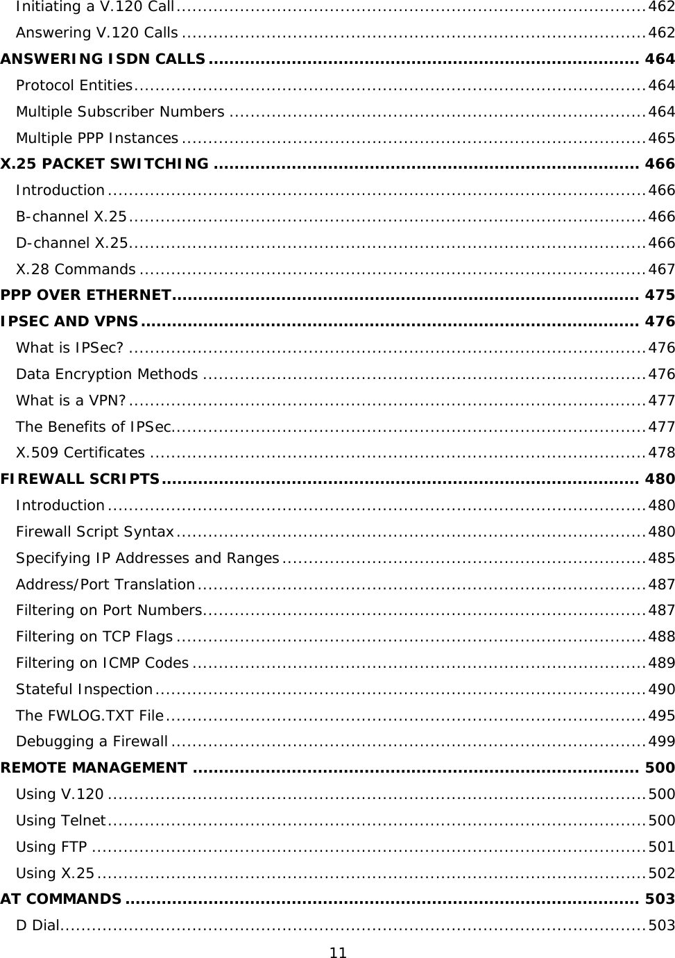
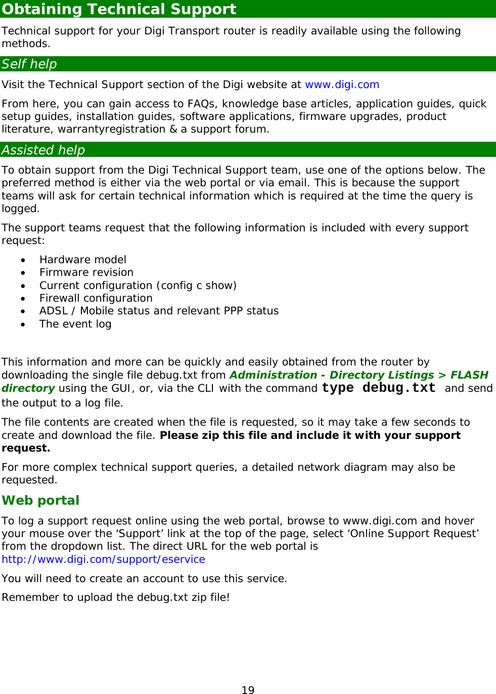
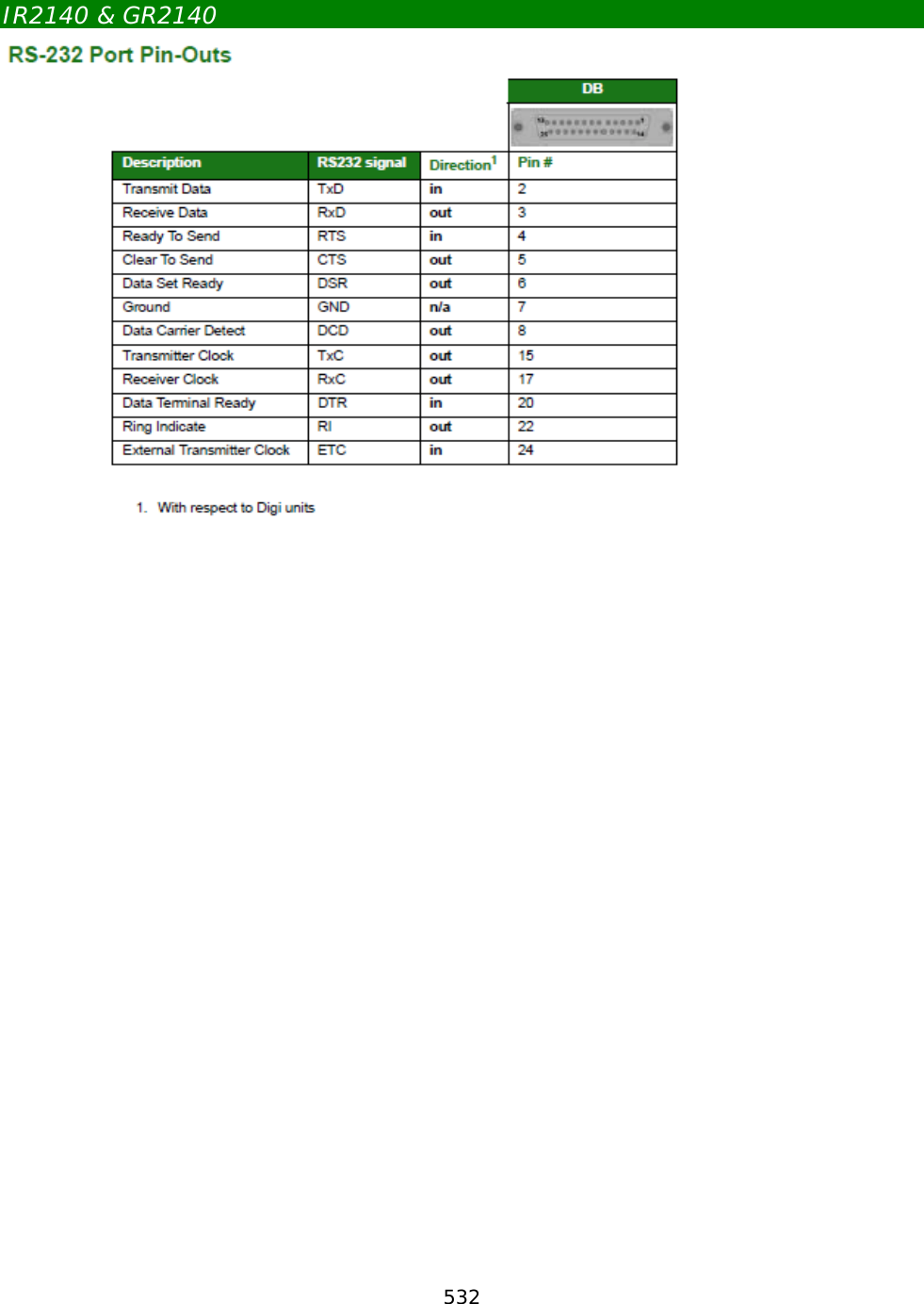
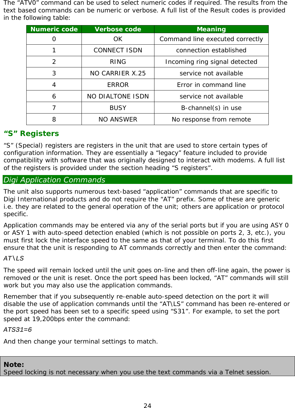
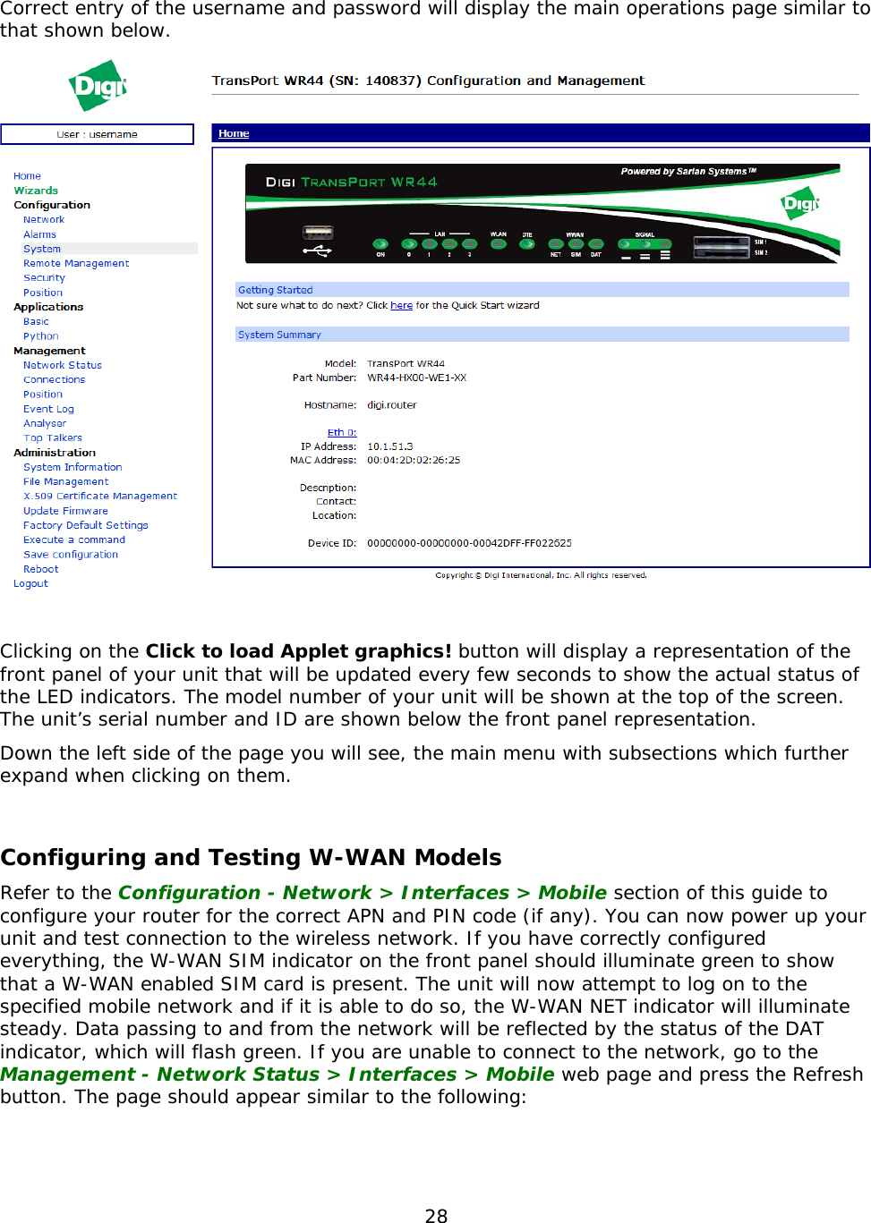
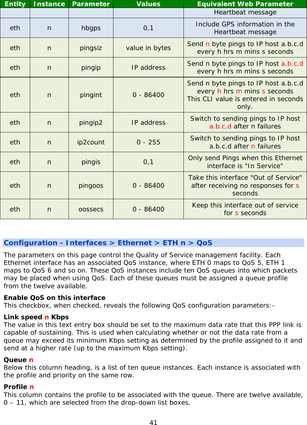
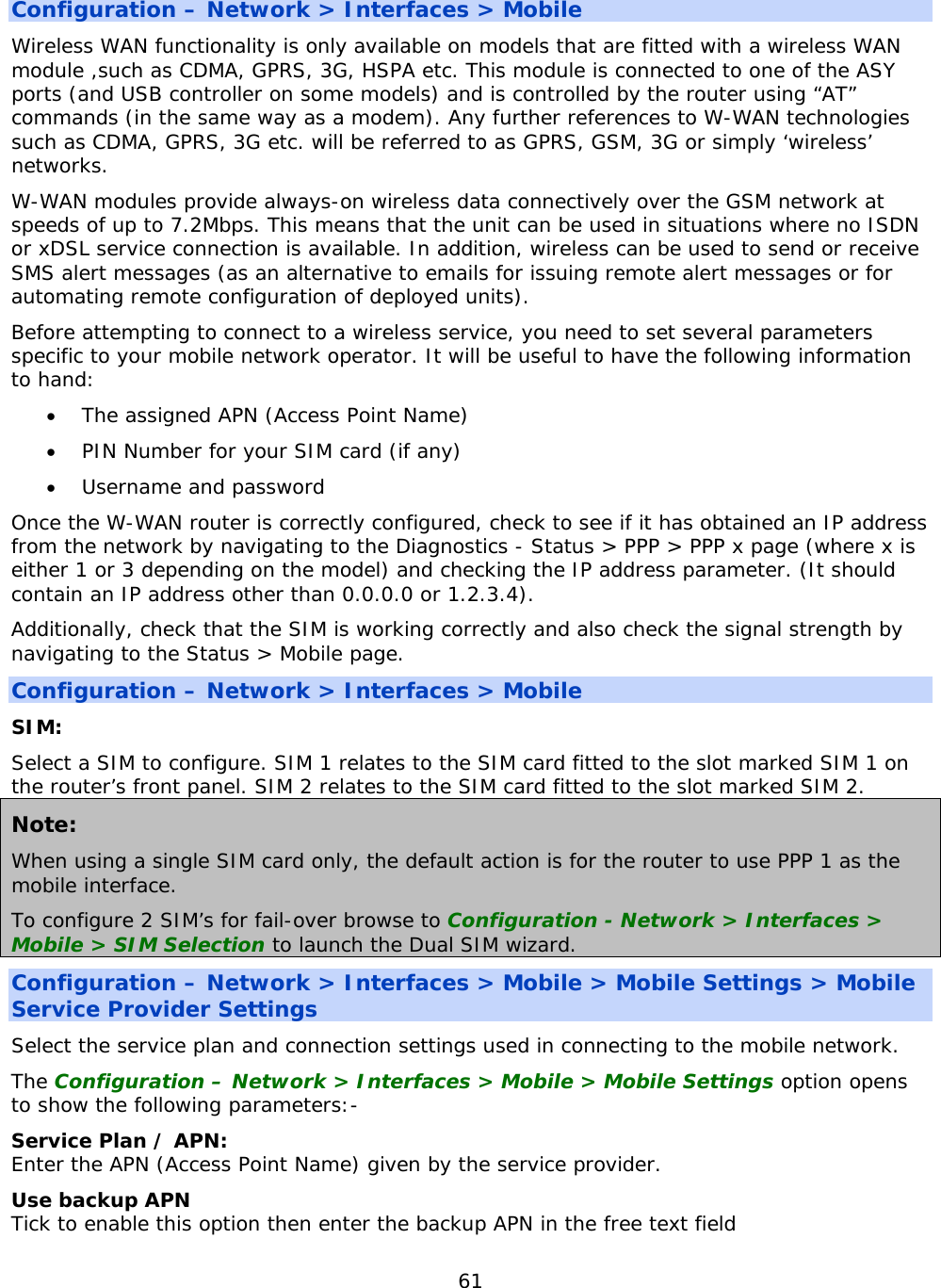
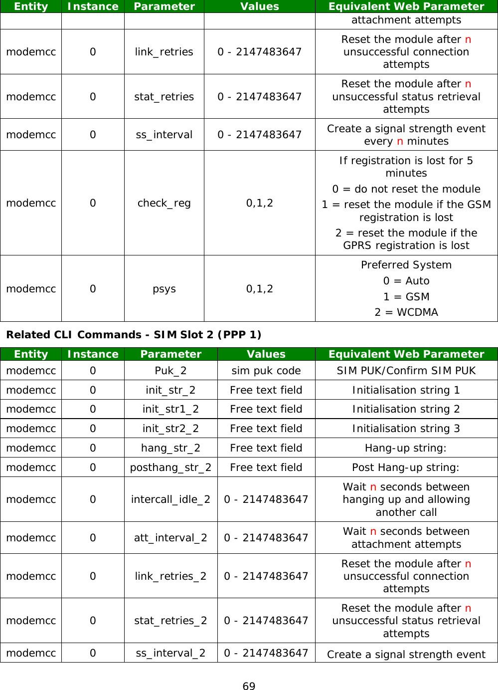
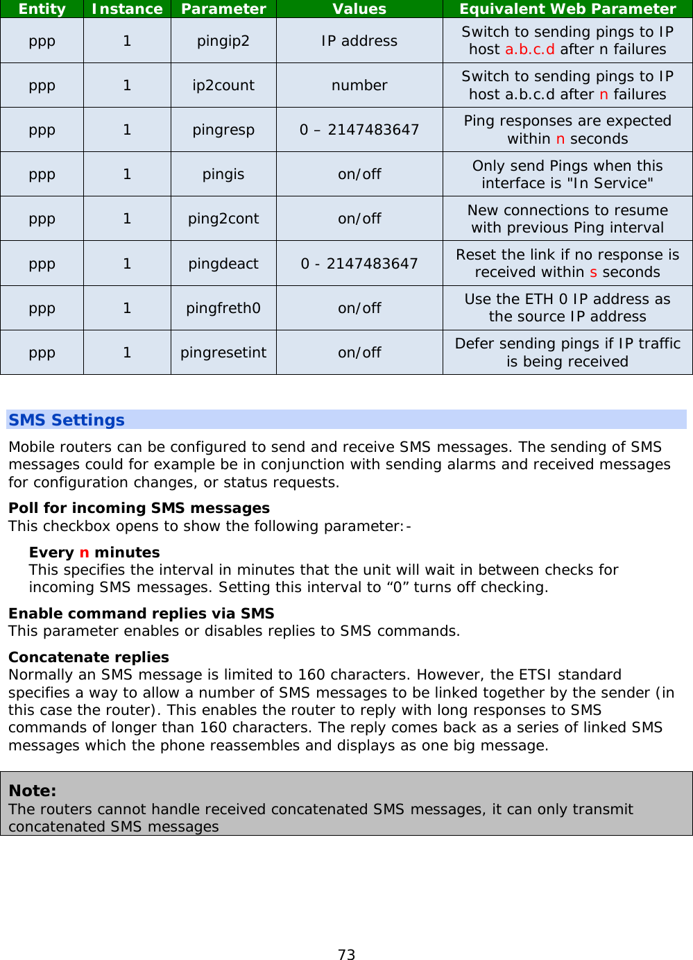
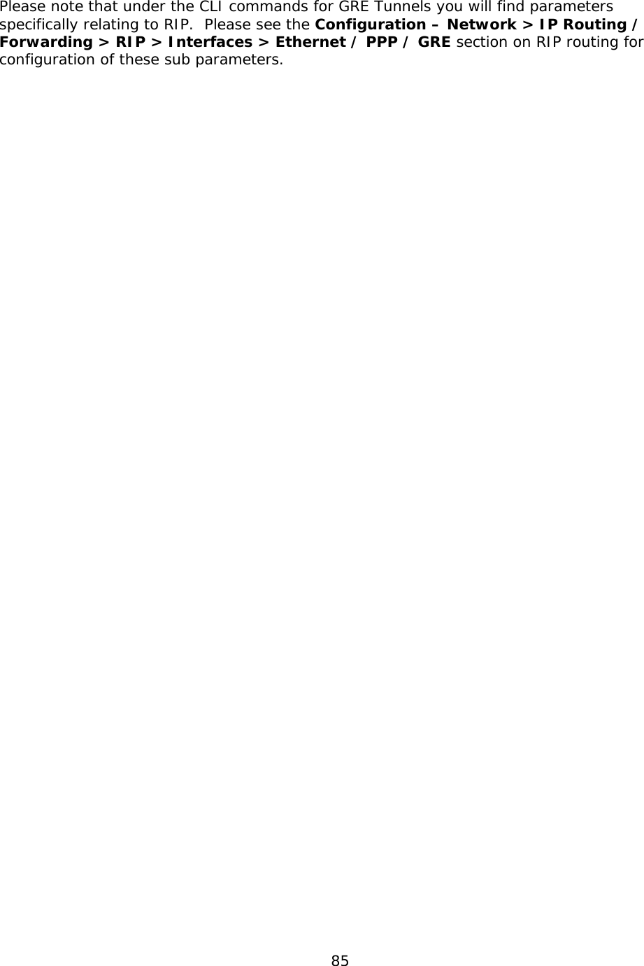
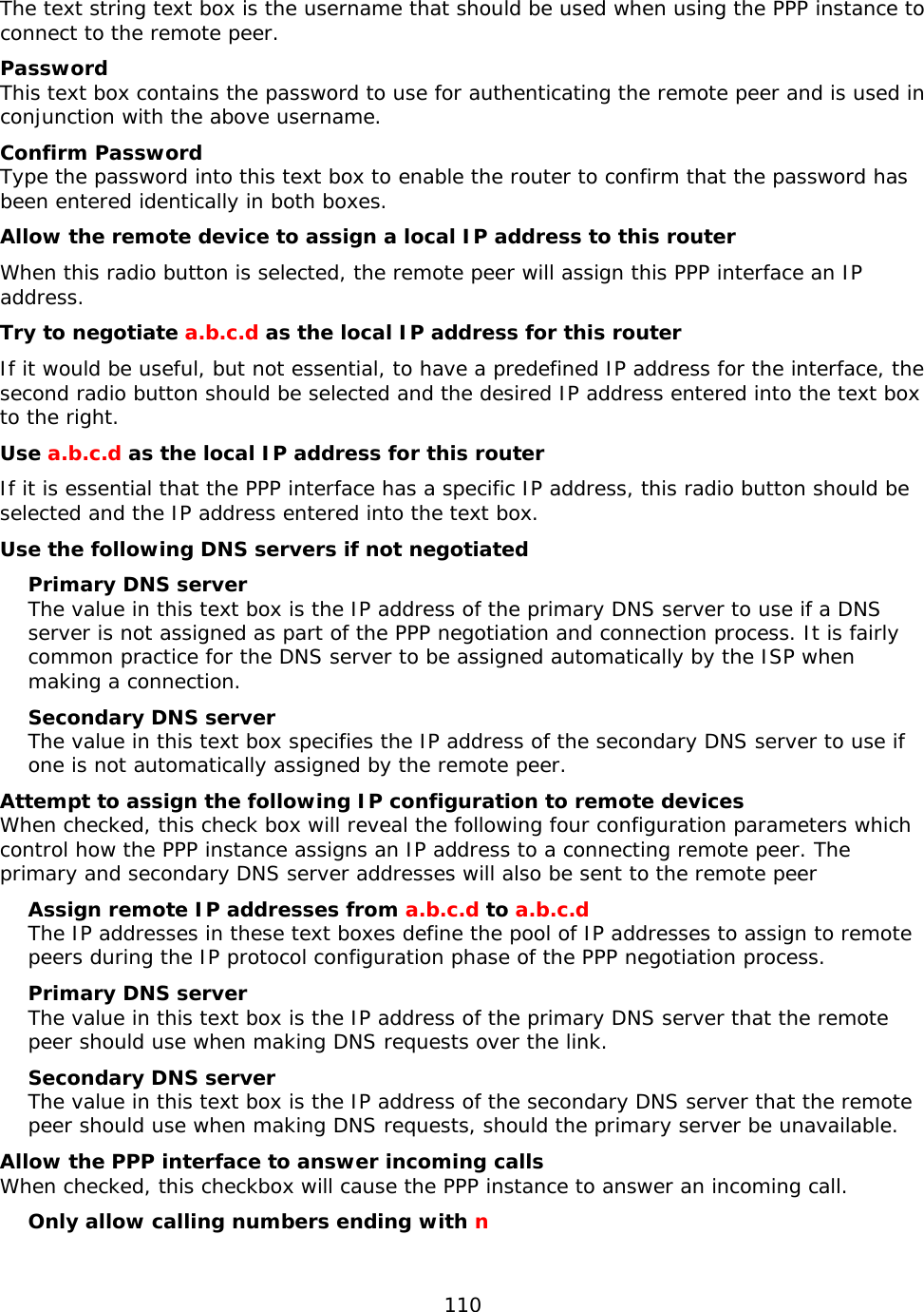
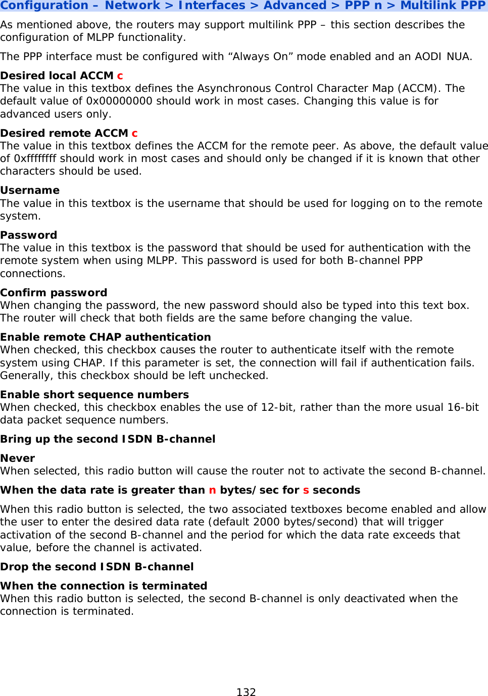
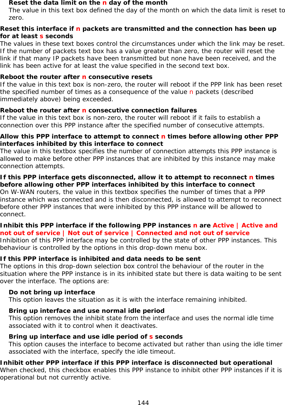
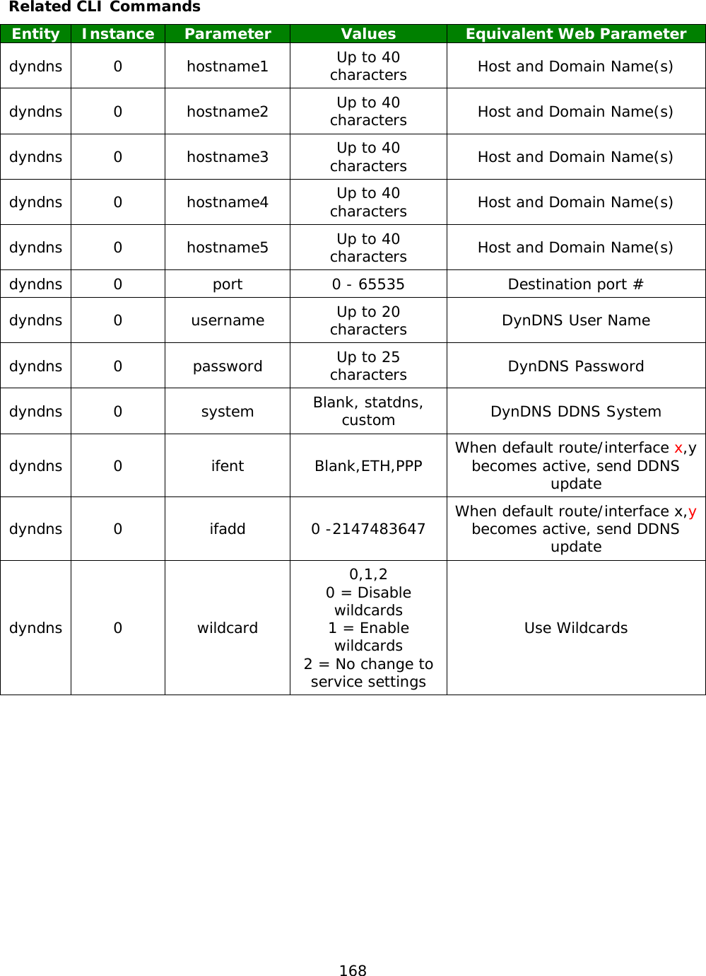
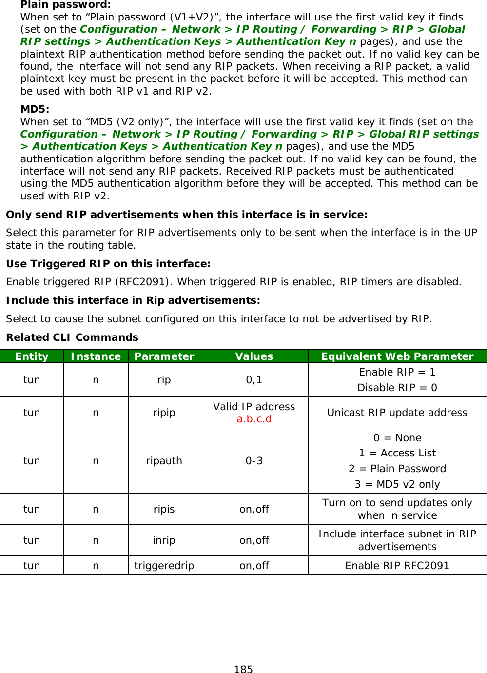
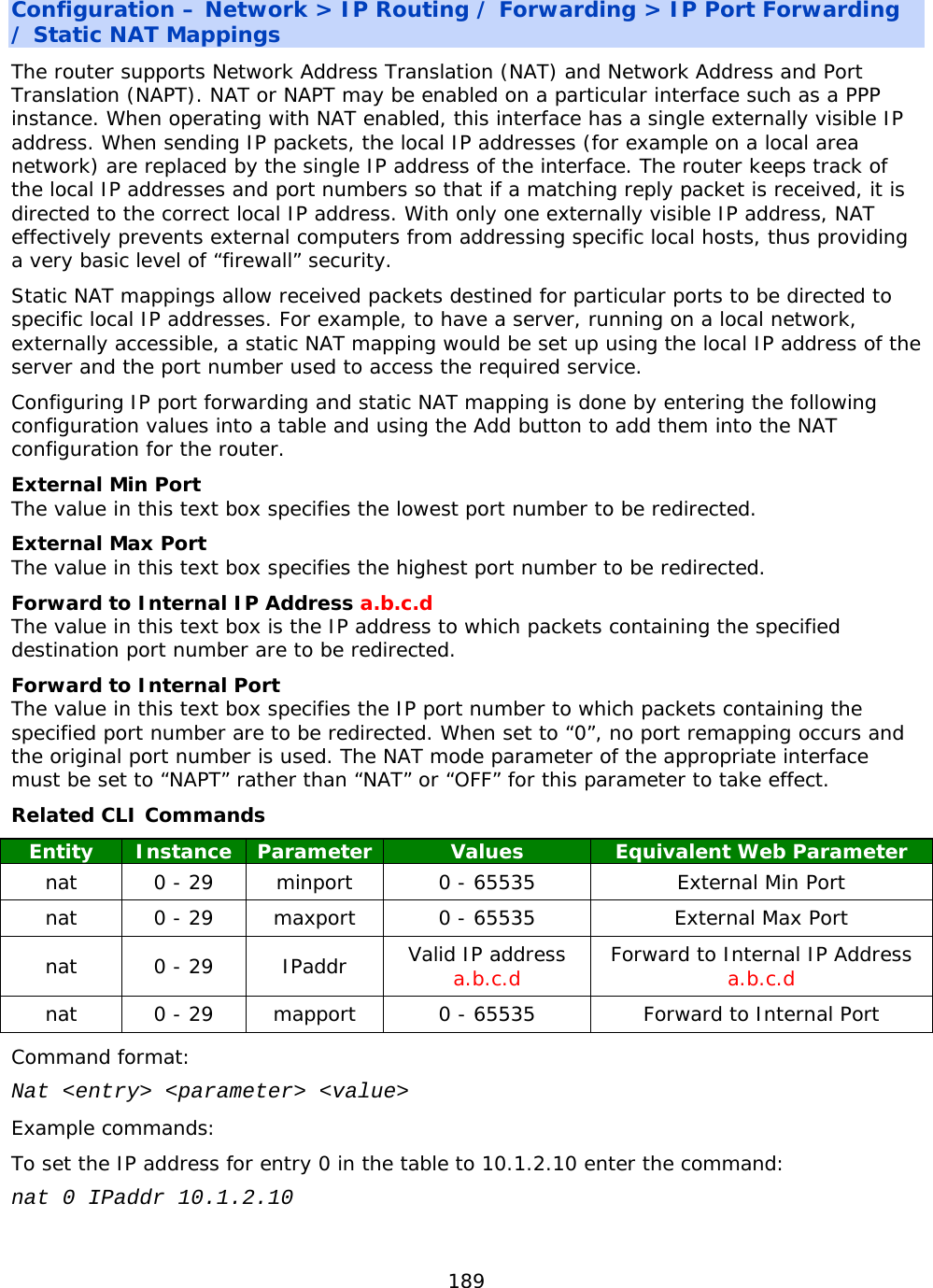
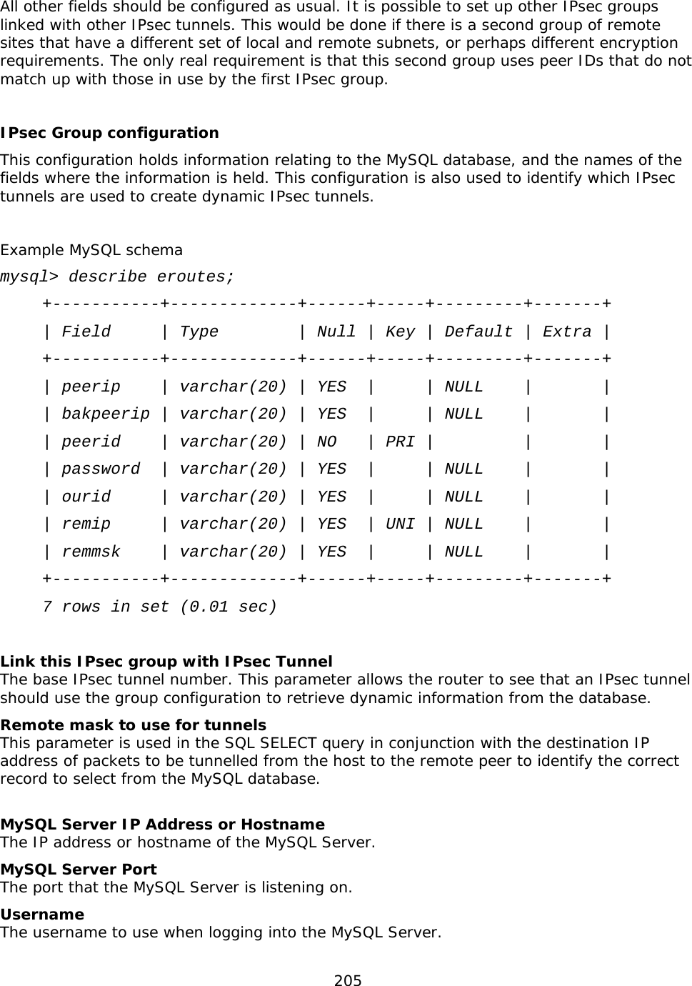
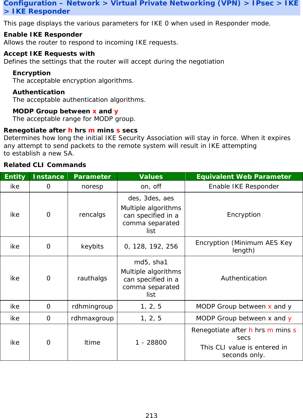
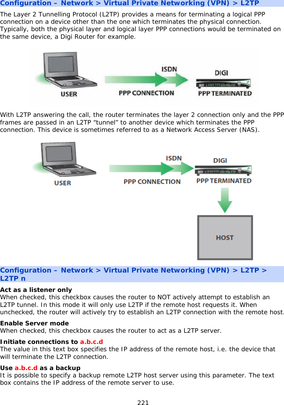
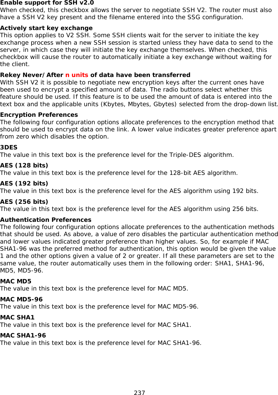
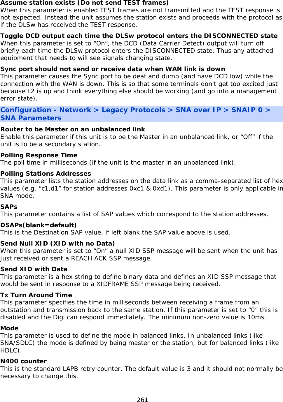
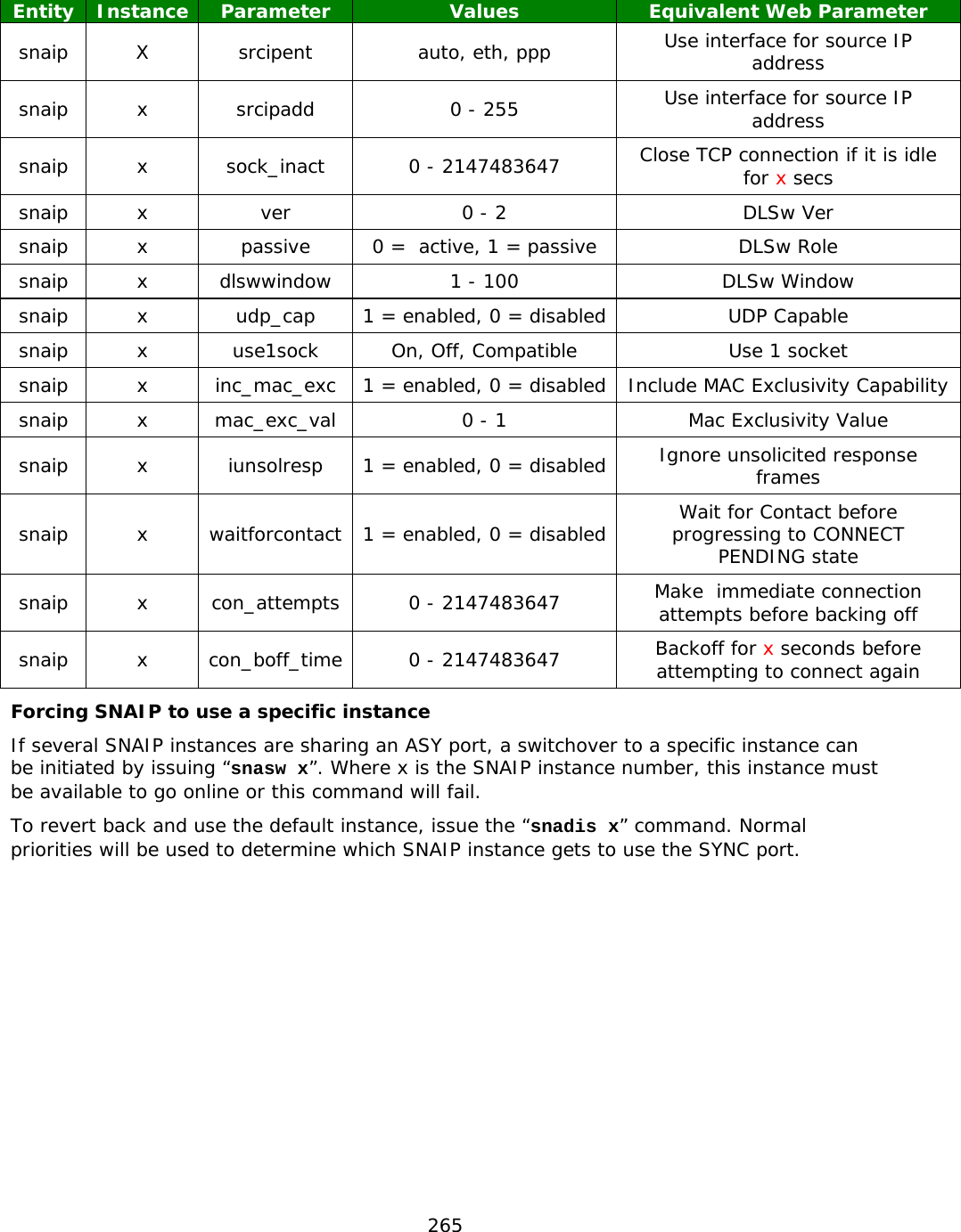
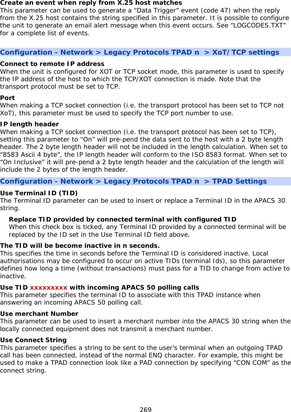
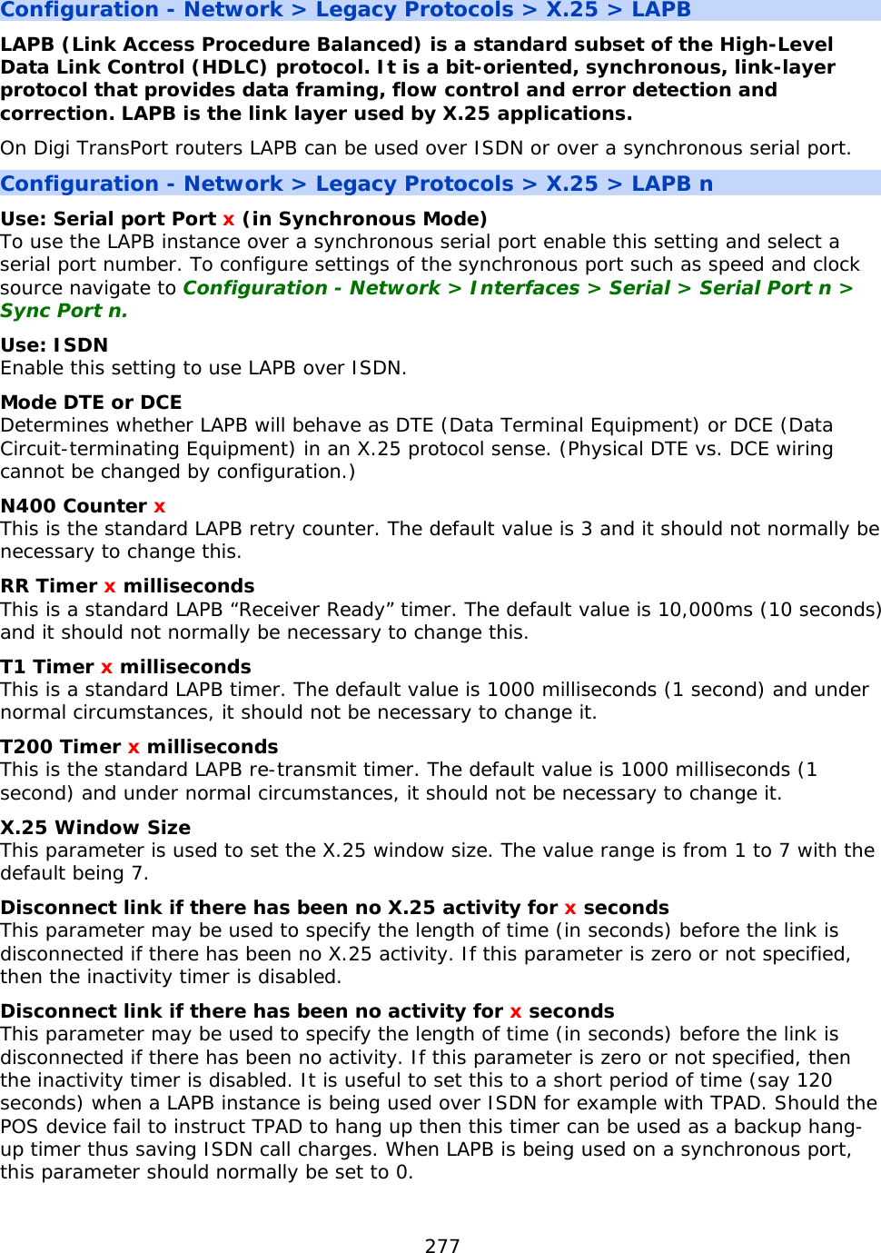
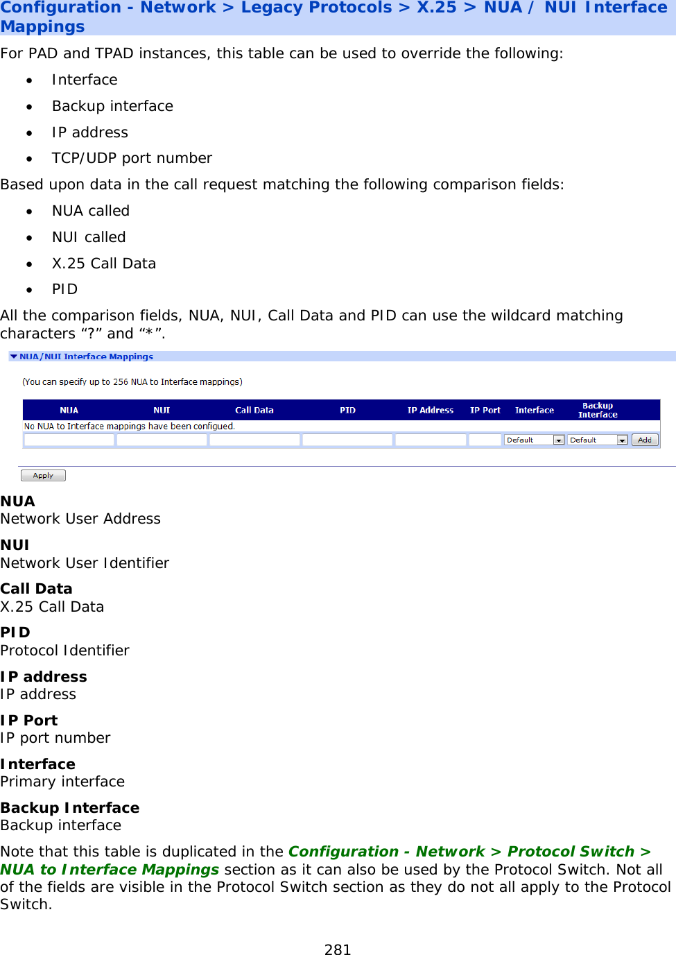
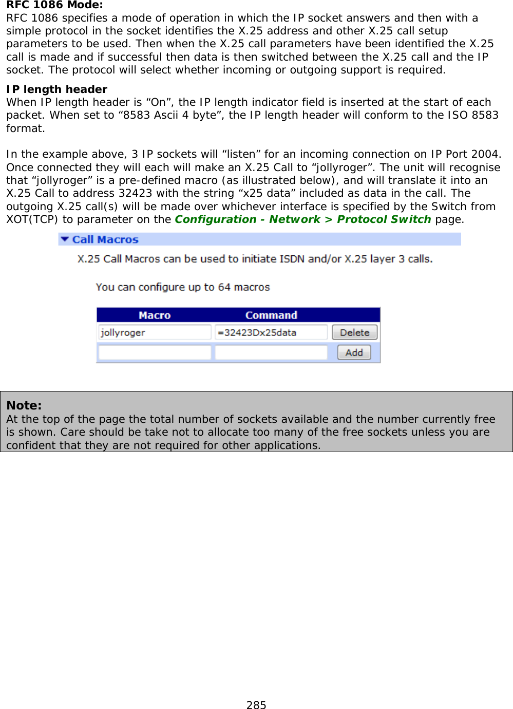
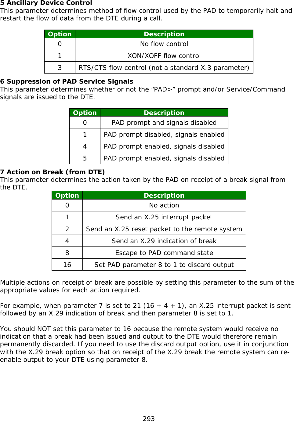
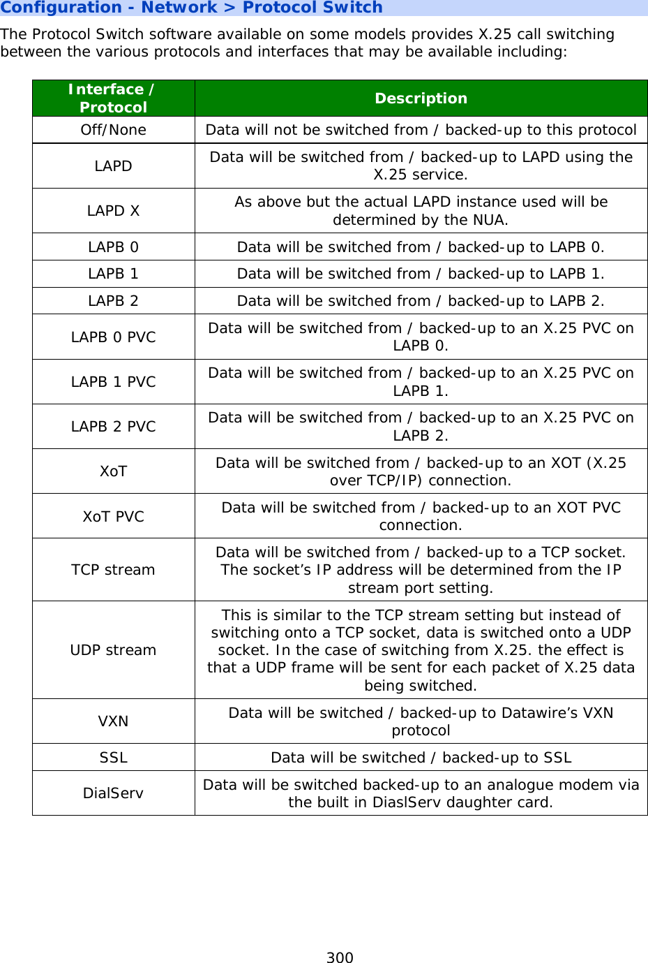
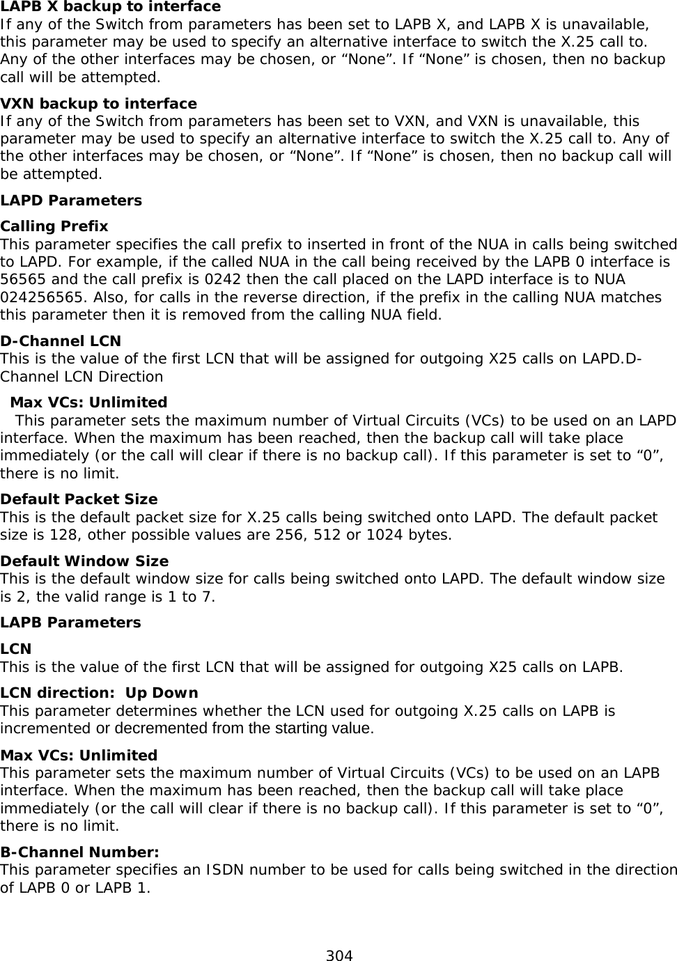
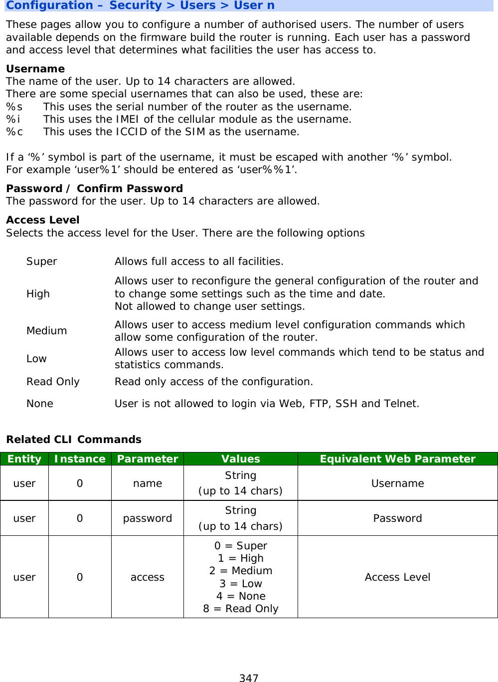
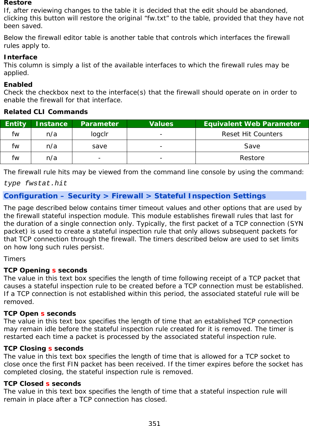
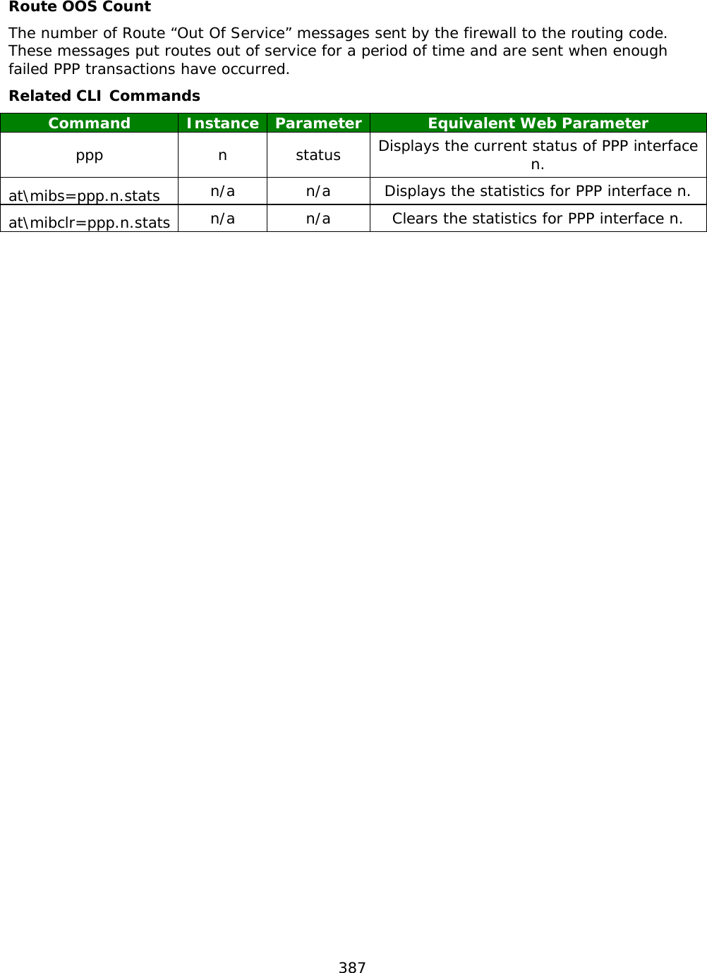
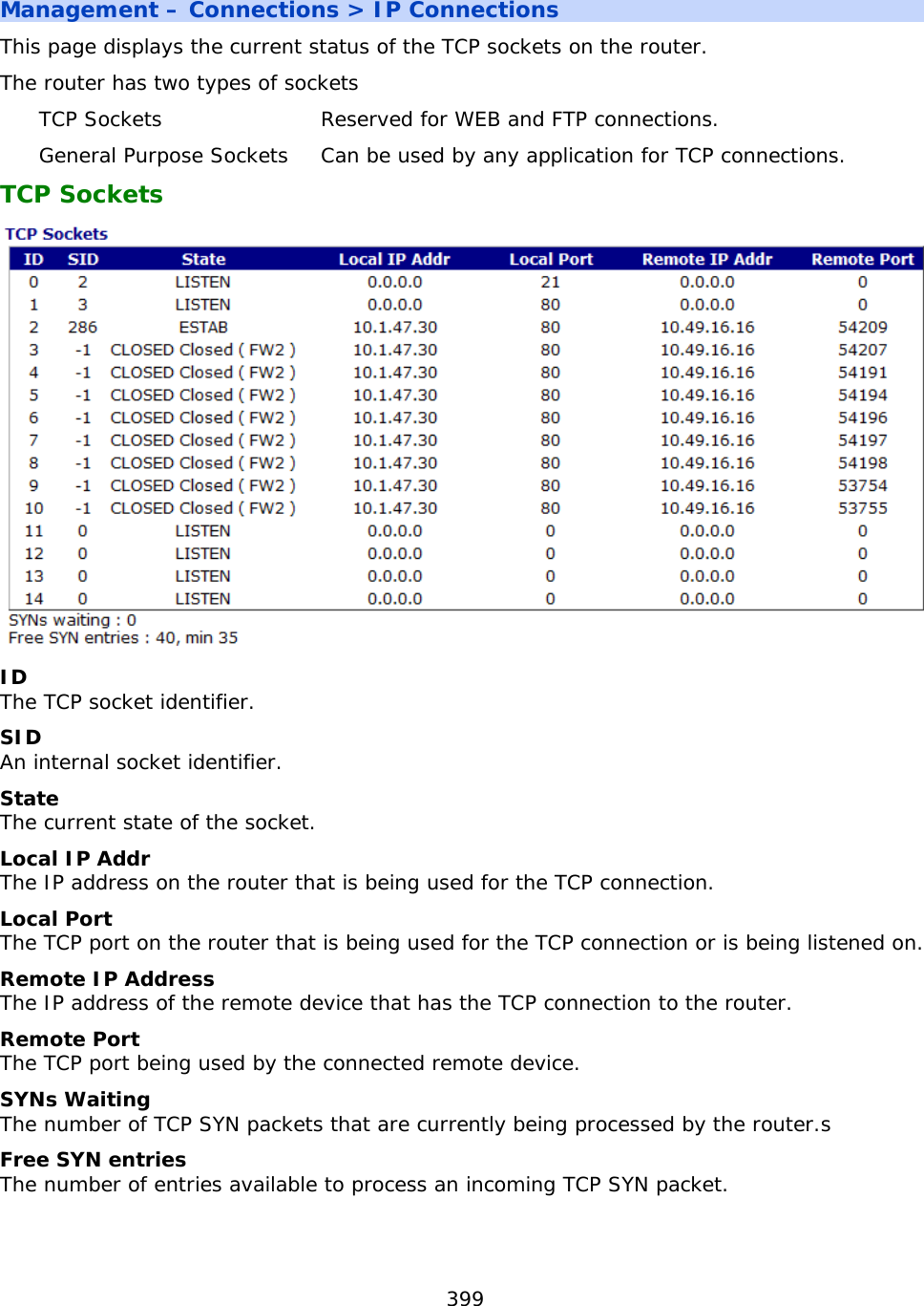
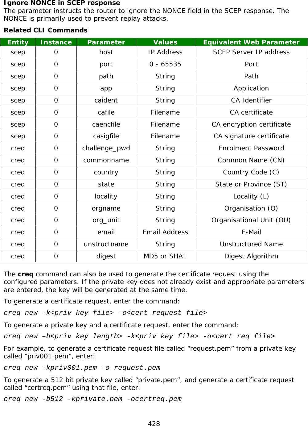
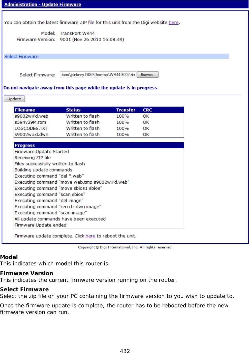
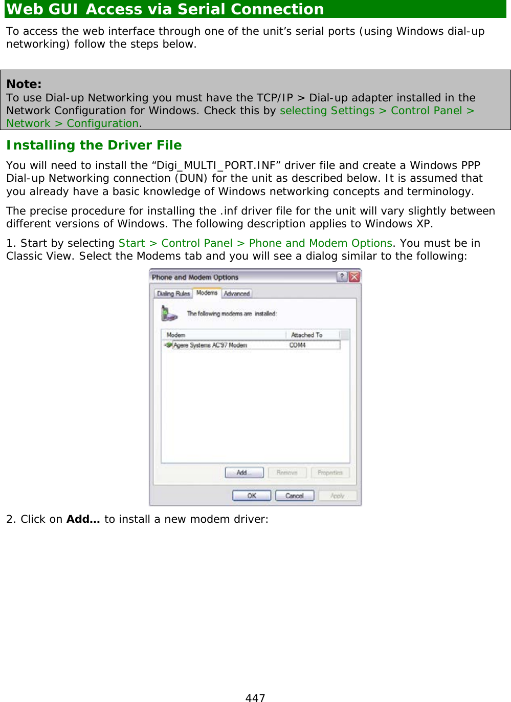
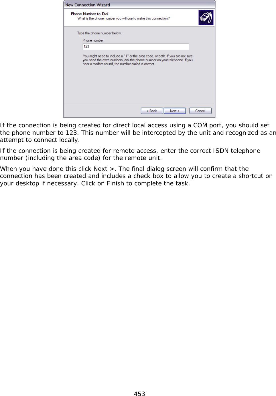
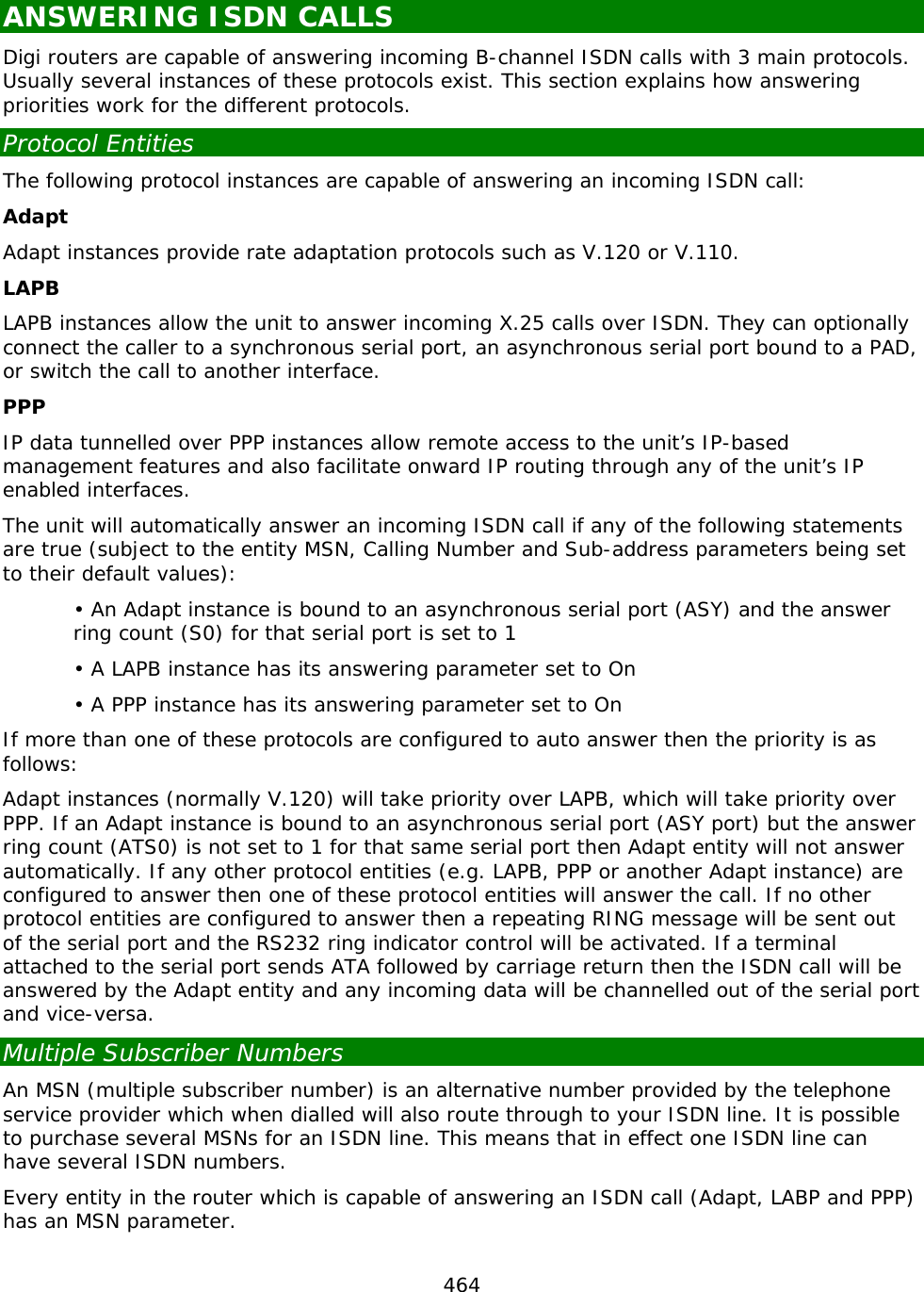
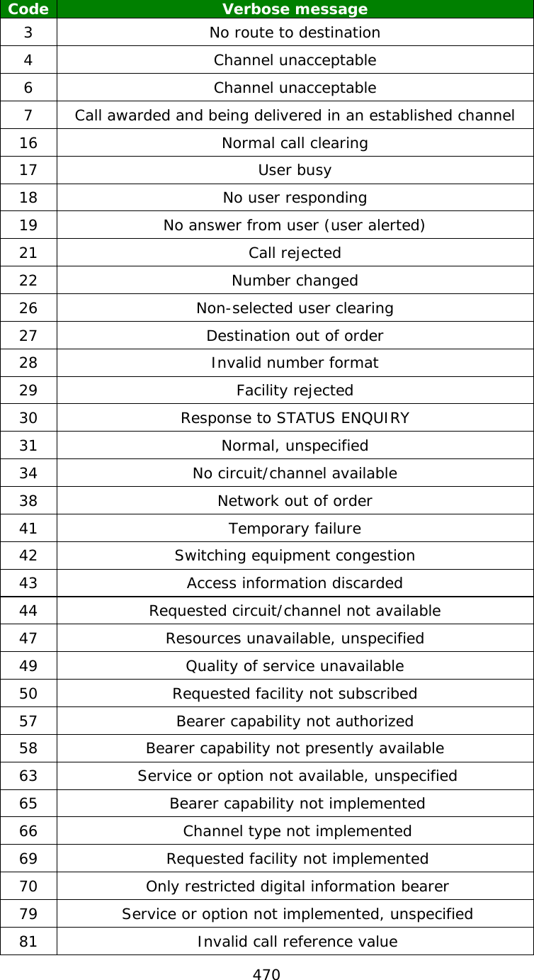
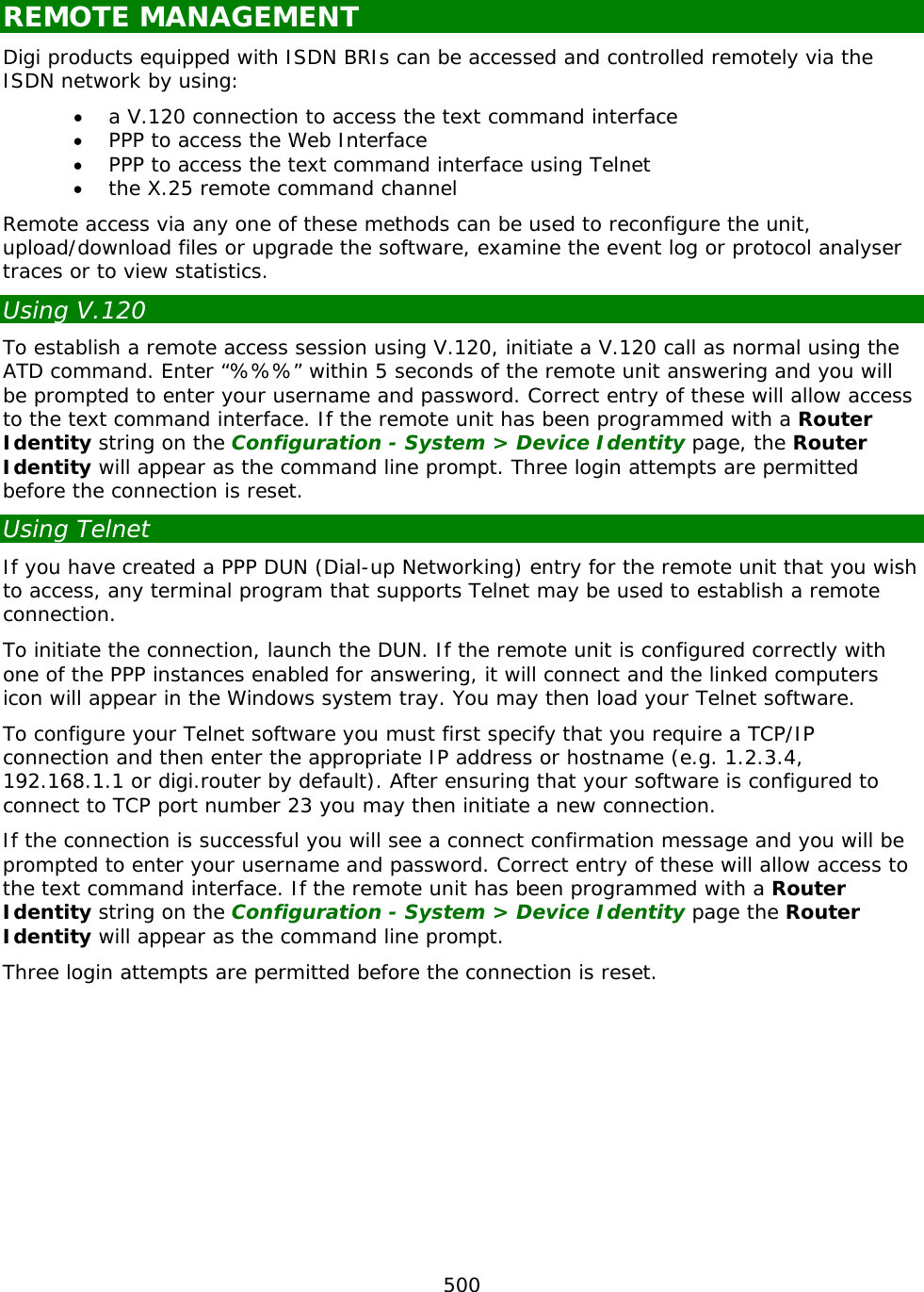
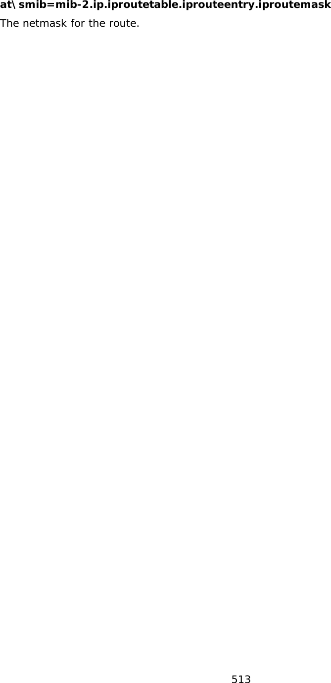
![21 Using the Command Line Interface Using a Web browser to modify text box or table values in the configuration pages is the simplest way to configure the unit and this process is described in the next chapter. However, if you do not have access to a Web browser, the unit can be configured using text commands. These commands may be entered directly at one of the serial ports or via a Telnet session. Remote configuration is also possible using Telnet or X.25. To use the serial ports you will need a PC and some communications software such as HyperTerminal ™ (supplied with Windows) or TeraTerm™. The same commands may also be used to configure the unit remotely via Telnet, X.25 or V.120. There are several types of text command: AT Commands & S Registers AT commands (pronounced “ay tee”) and Special registers (S registers) are supported in order to maintain compatibility with modems when the unit is used as a modem replacement. Application Commands Application commands are specific to Digi International products and are used to control most features of the unit when not using the Web interface. X.3 Commands These are standard X.3 commands which are used only in X.25 PAD mode TPAD Commands These are used only in TPAD mode. The “AT” Command Interface Command Prefix The “AT” command prefix is used for those commands that are common to modems. To configure the unit using AT commands you must first connect it to a suitable asynchronous terminal. You will first need to set the interface speed/data format for your terminal to 115,200bps, 8 data bits, no parity and 1 stop bit (these settings can be changed later if necessary). When your terminal is correctly configured, apply power and wait for the B2 indicator to stop flashing. Unless you have previously configured the unit to automatically connect to a remote system on powerup, it will now be ready to respond to commands from an attached terminal and is in “command mode”. Now type “AT” (in upper or lower case), and press [Enter]. The unit should respond with the message “OK”. This message is issued after successful completion of each command. If an invalid command is entered, the unit will respond with the message “ERROR”. If there is no response, check that the serial cable is properly connected and that your terminal or PC communications software is correctly configured before trying again.](https://usermanual.wiki/Digi/55M1644B.Manual-pt-1/User-Guide-1821845-Page-21.png)
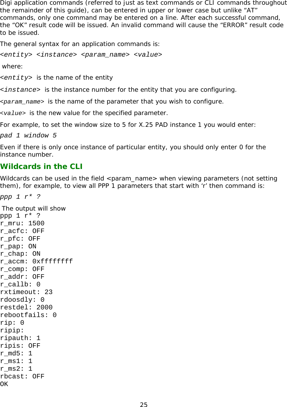
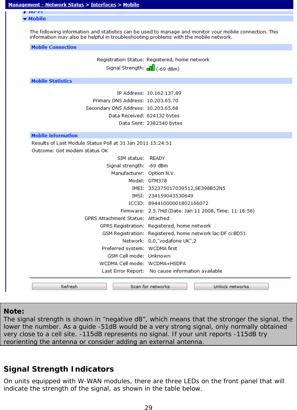

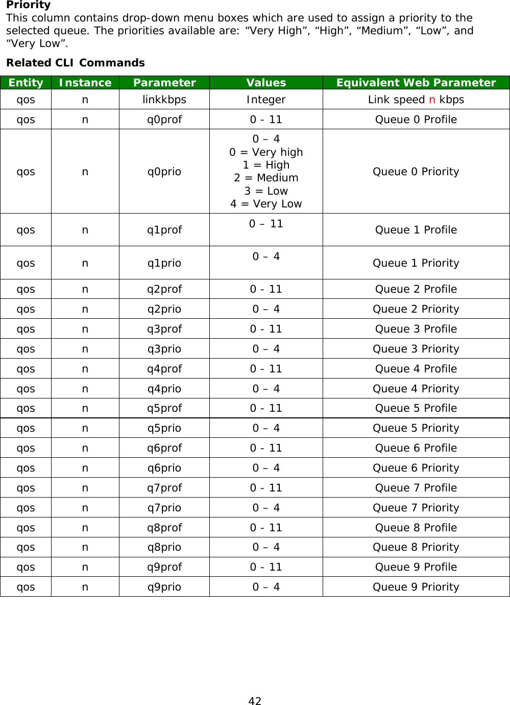
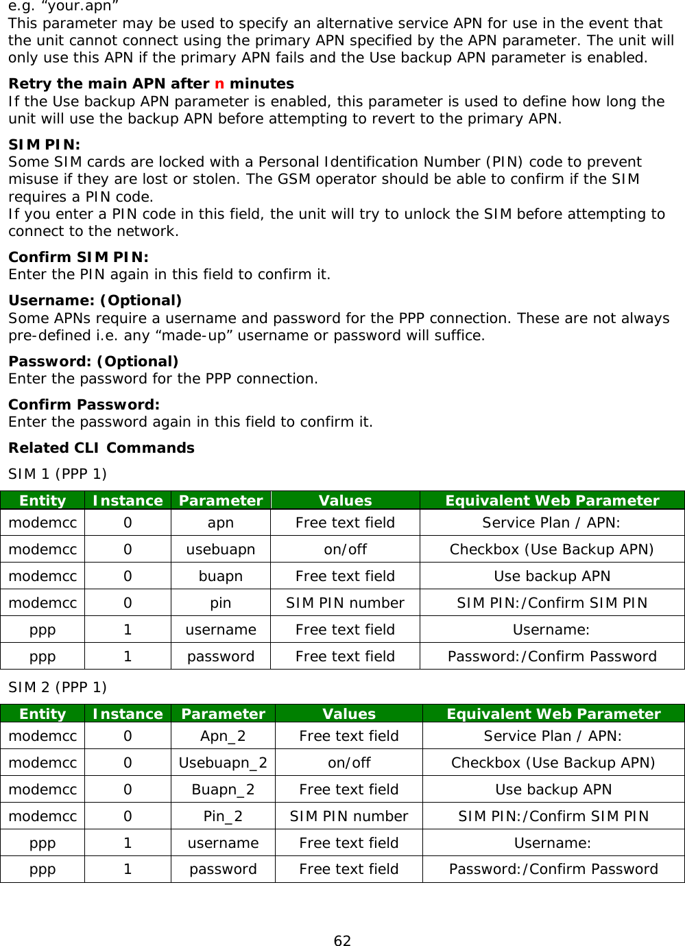
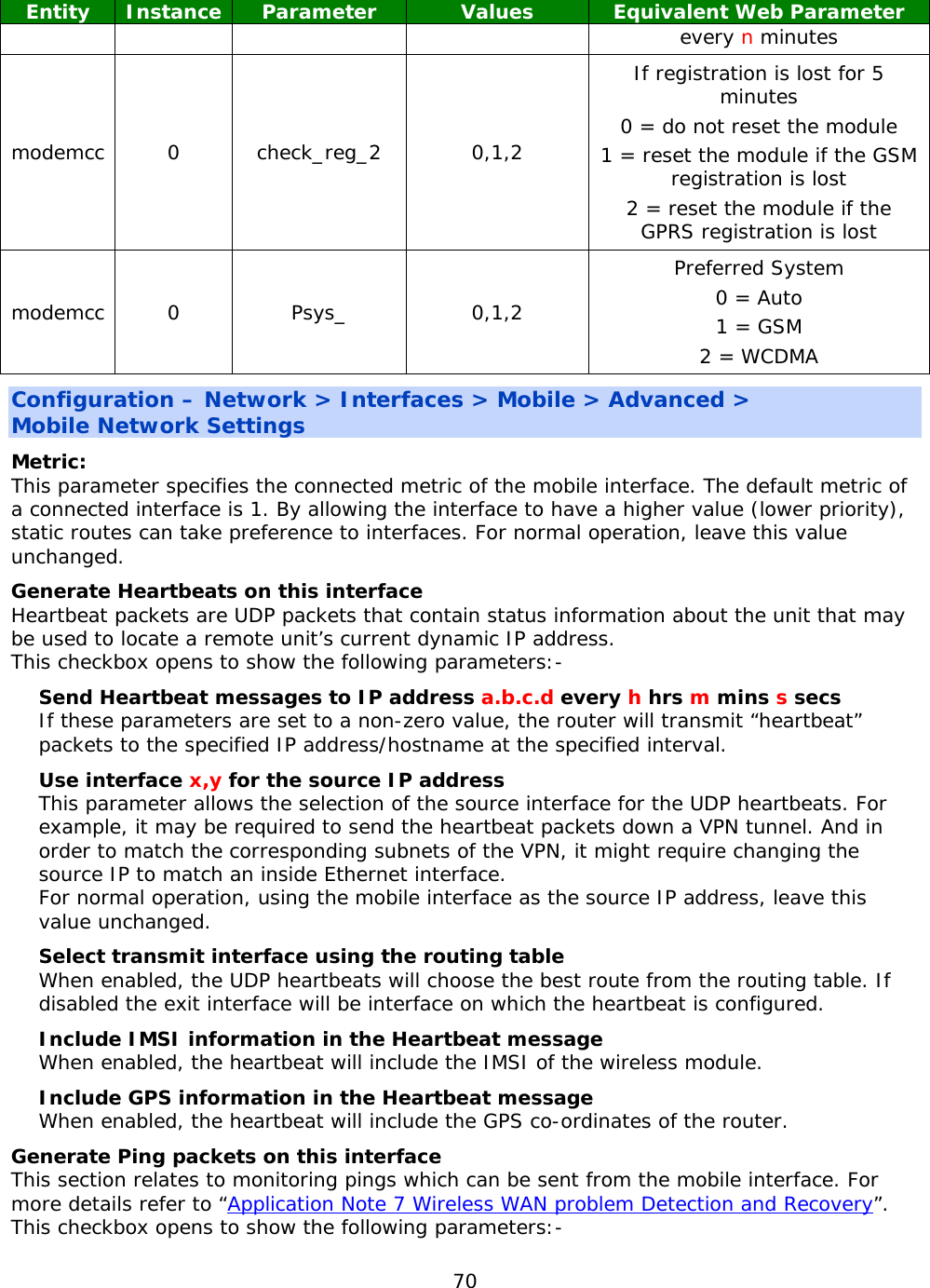
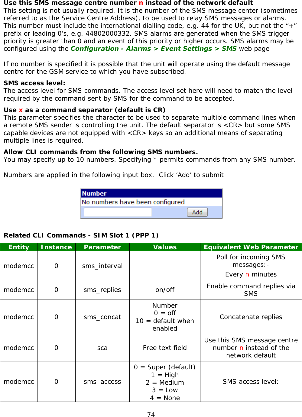
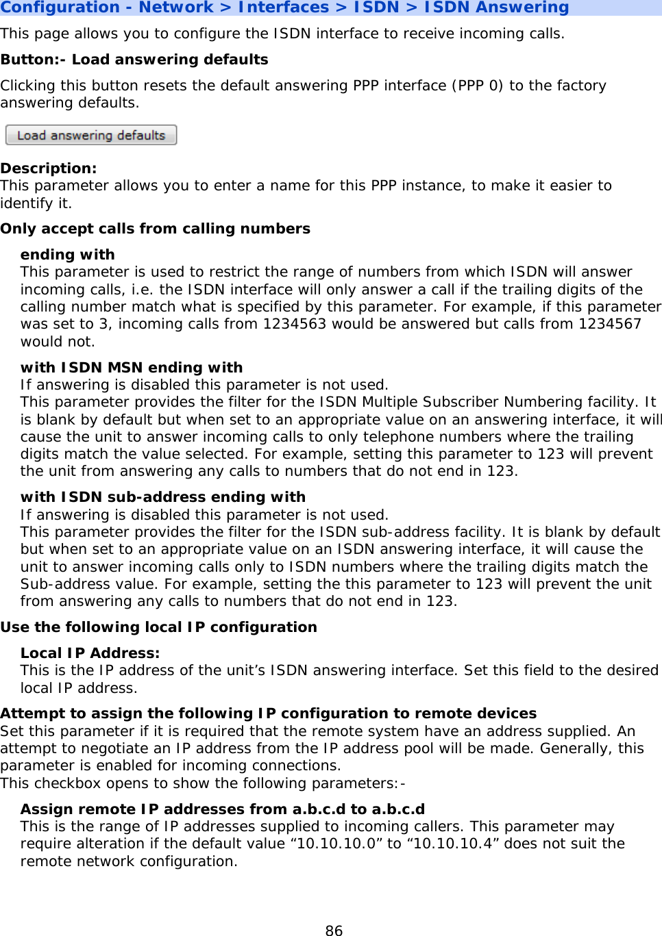

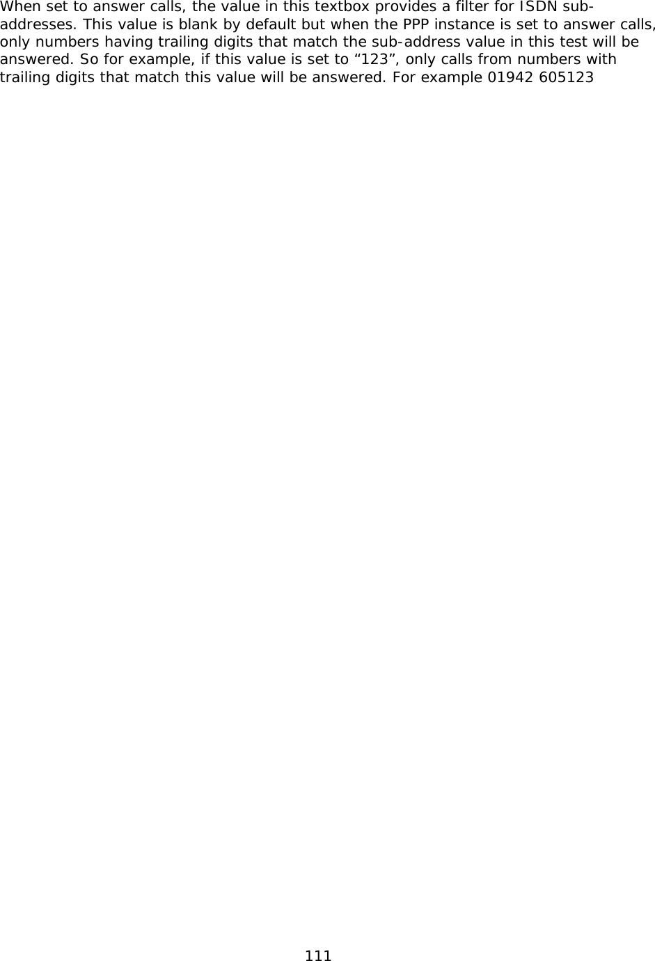


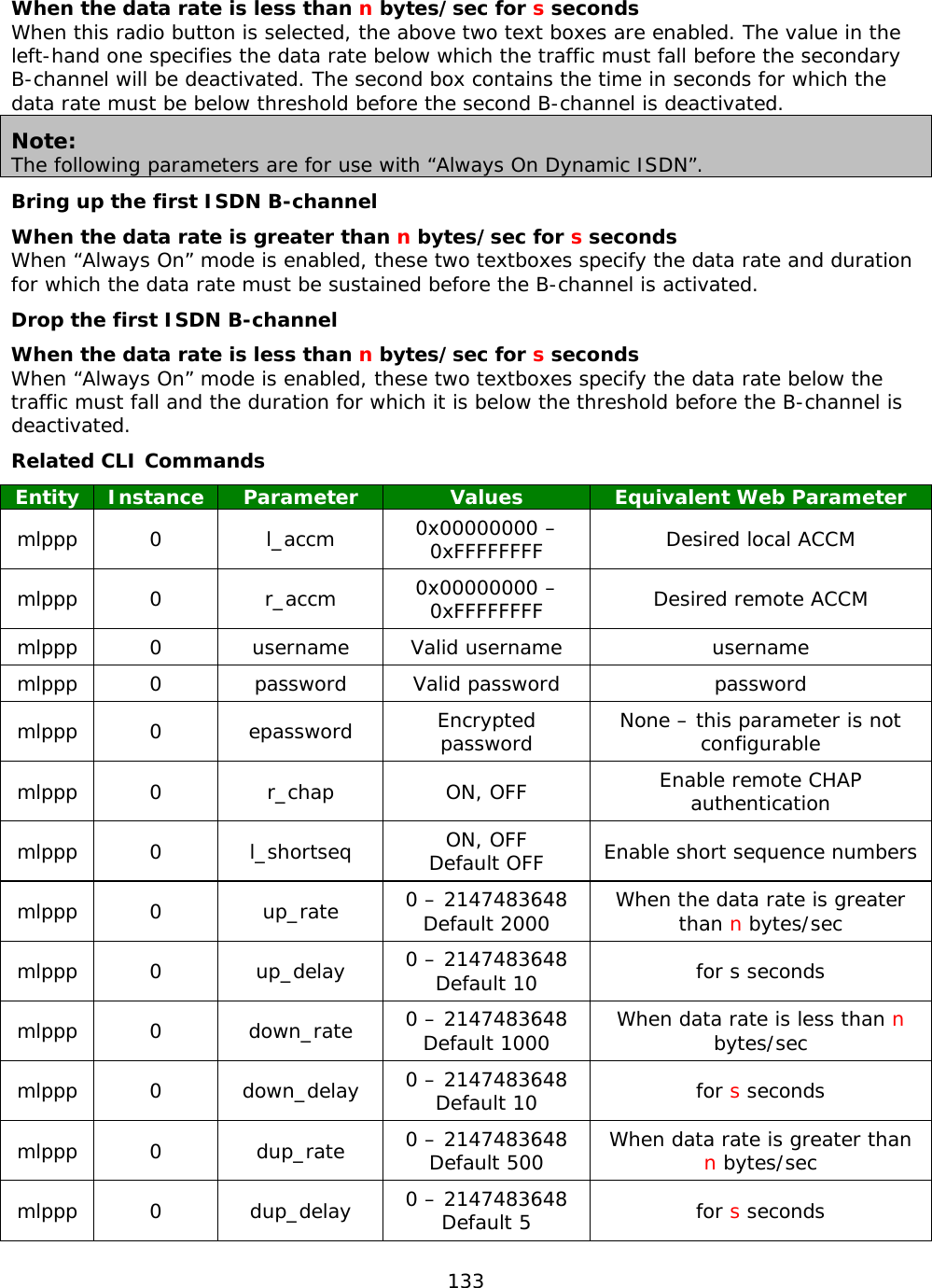
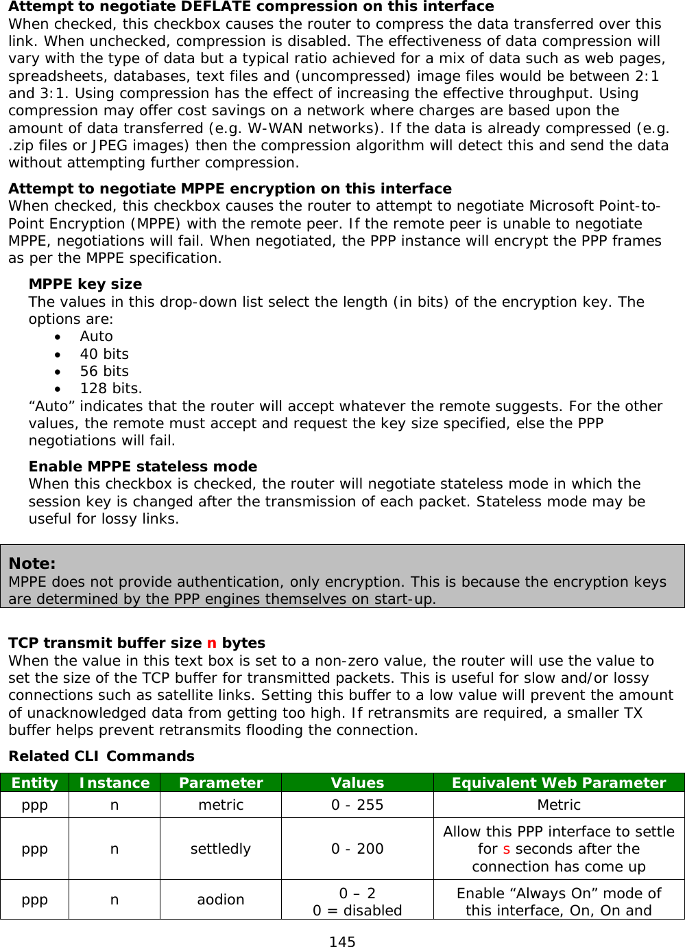
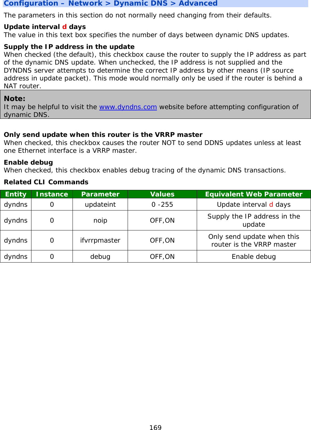
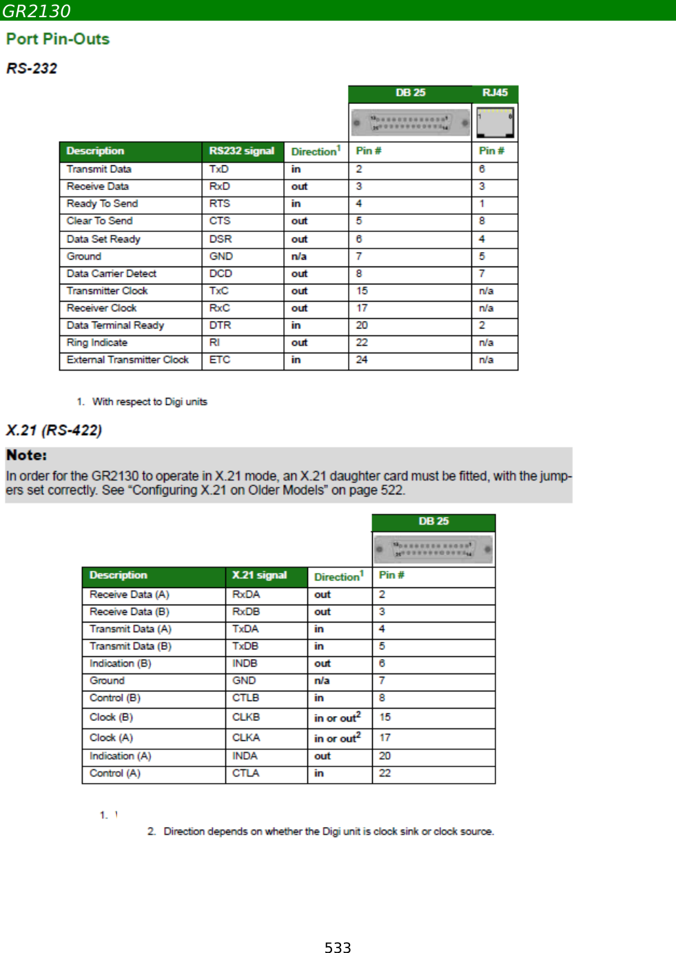
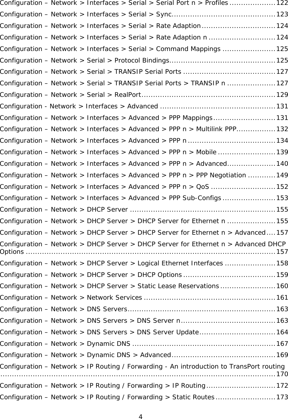
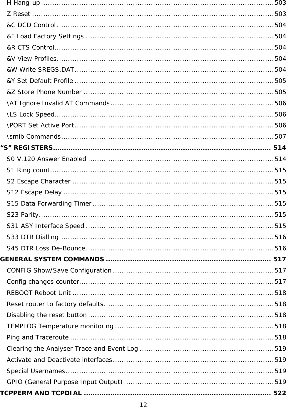
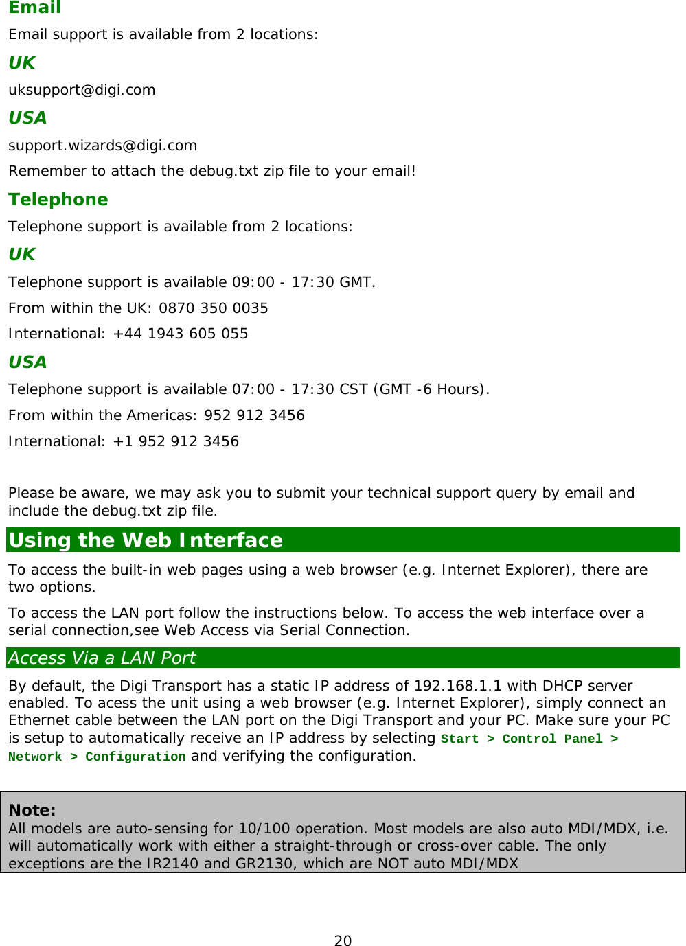
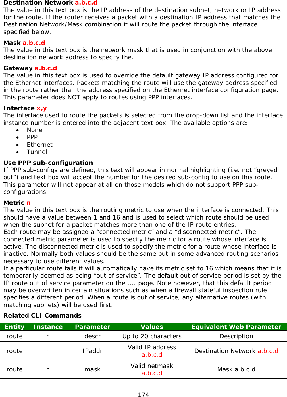
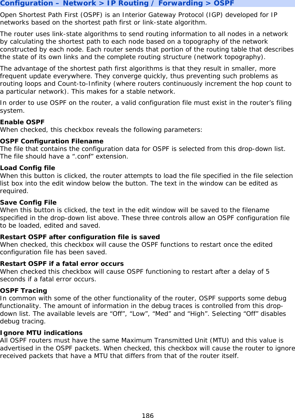
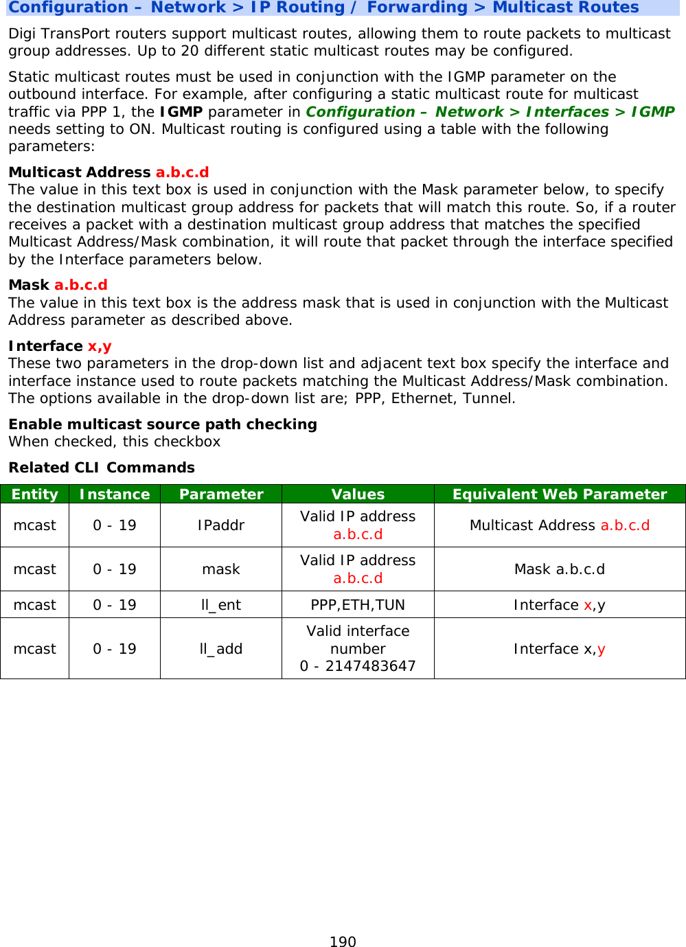
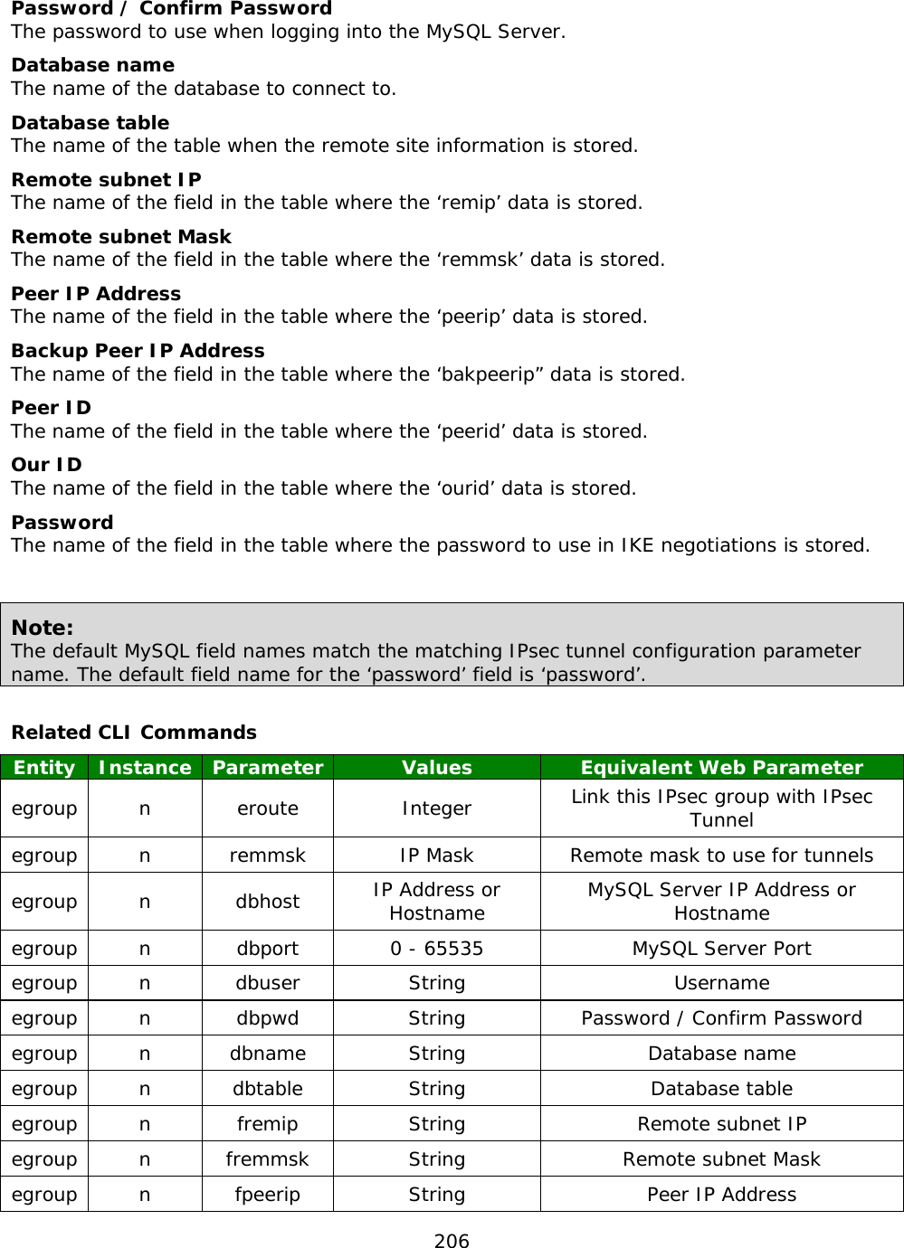
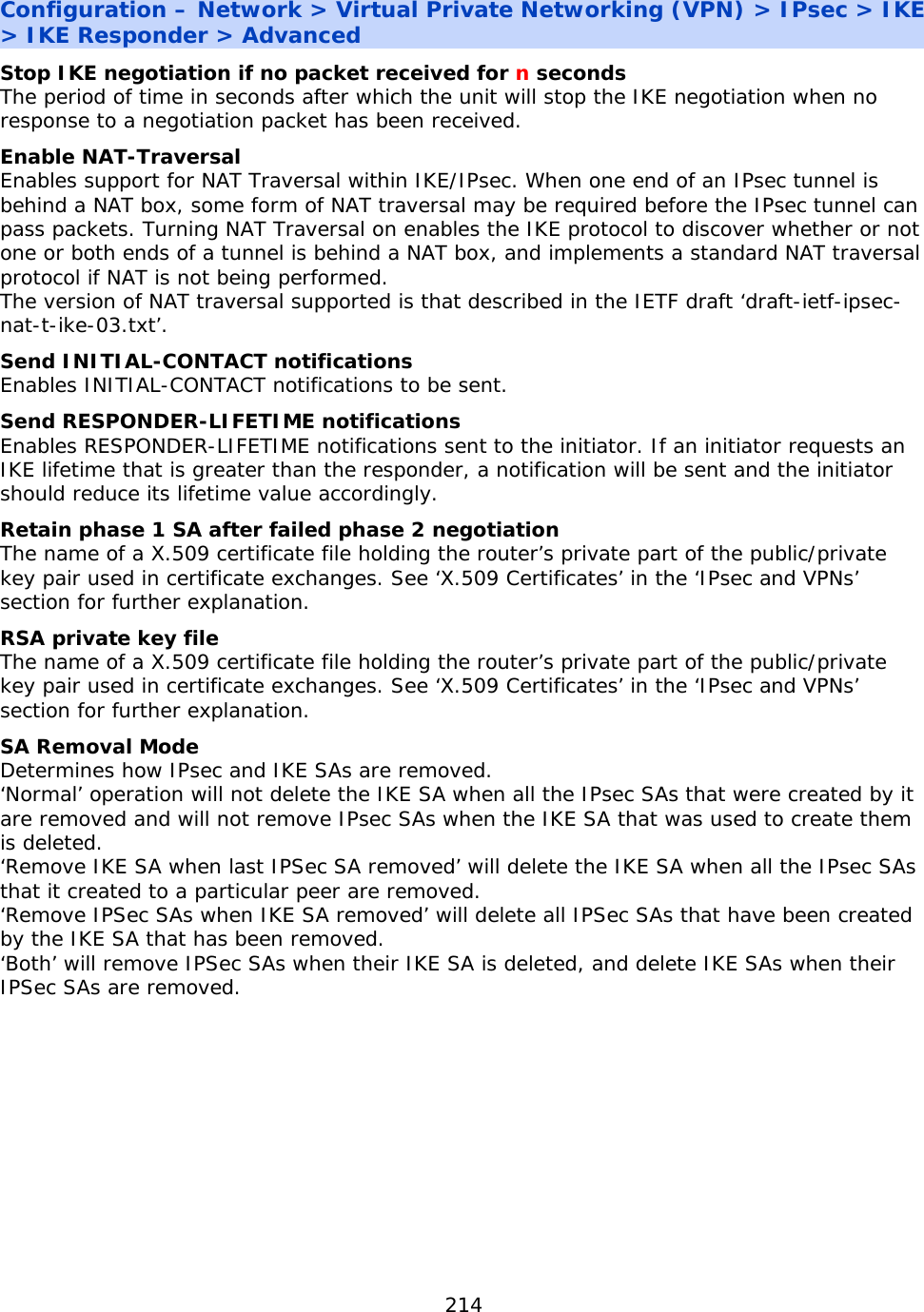
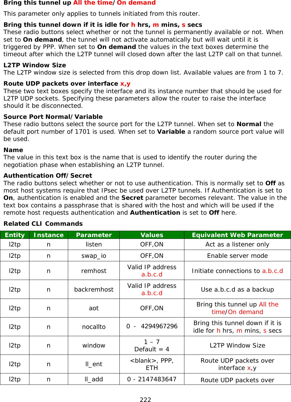
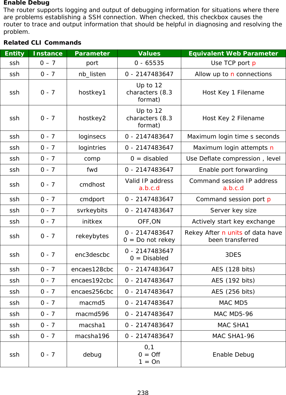
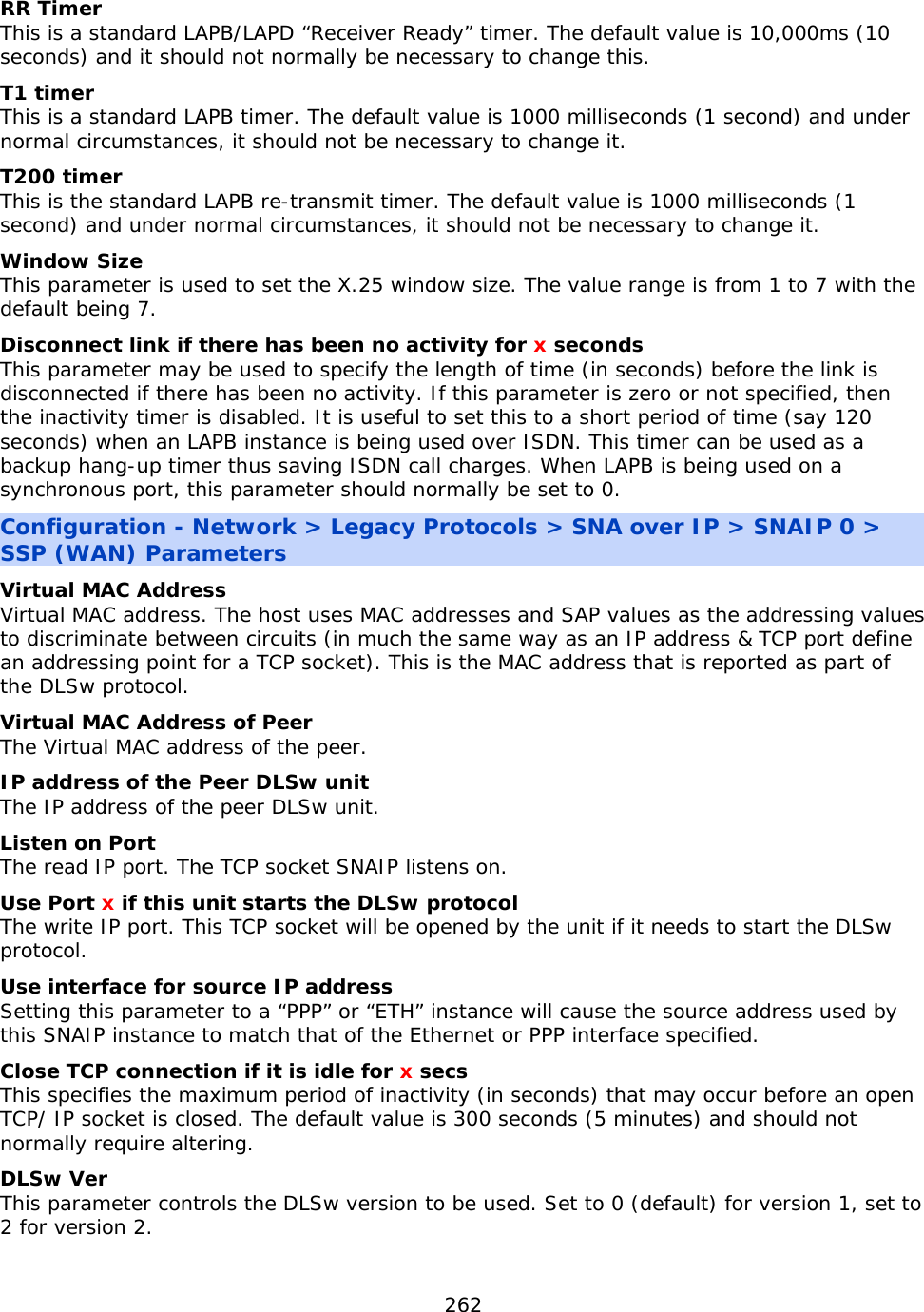
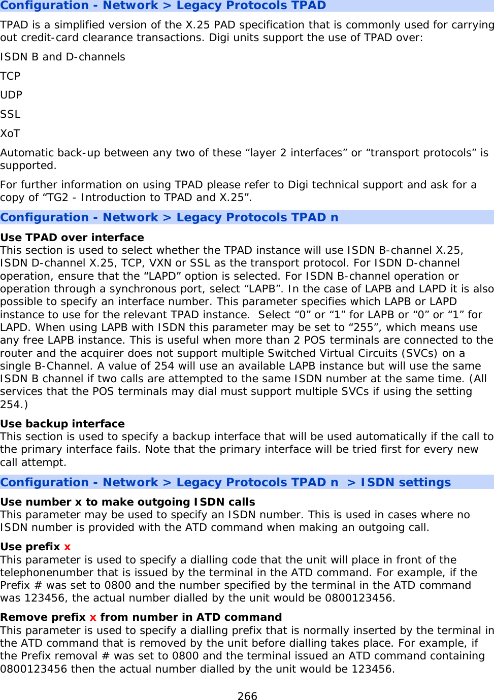
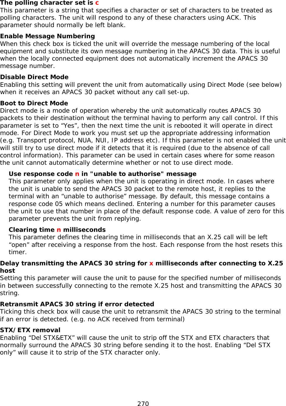
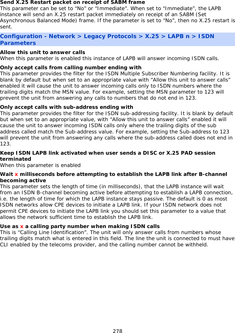
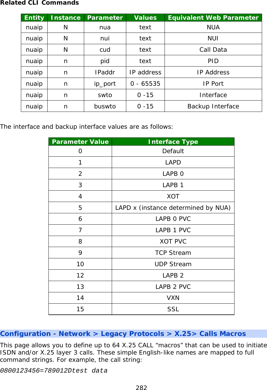
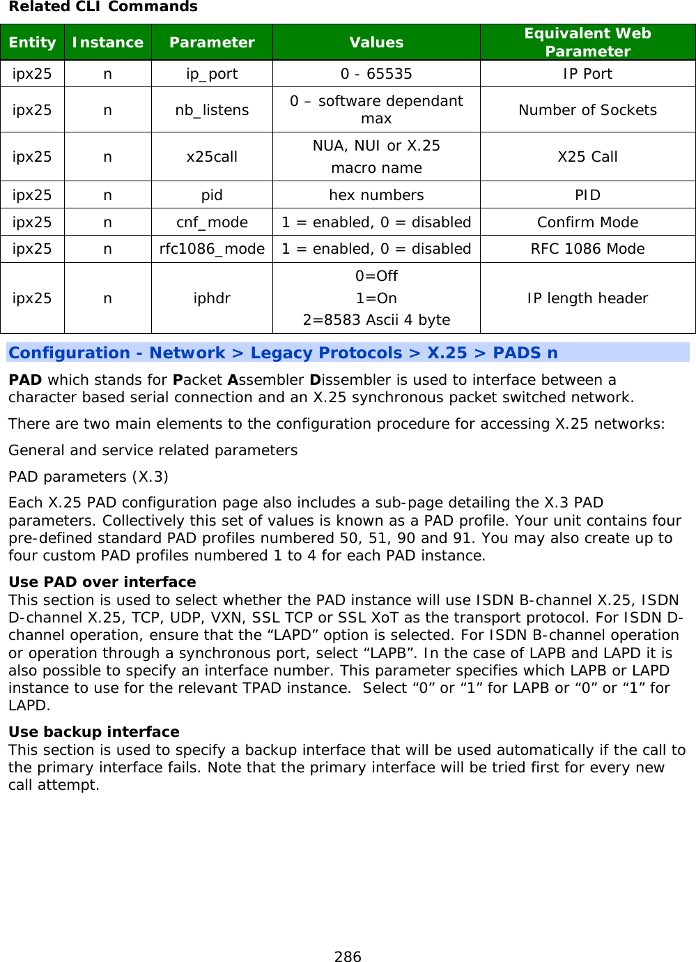
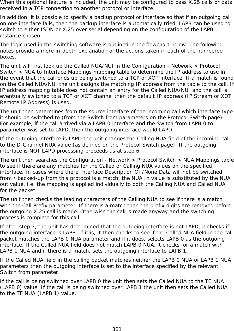
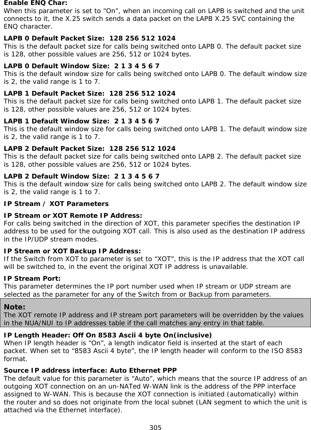
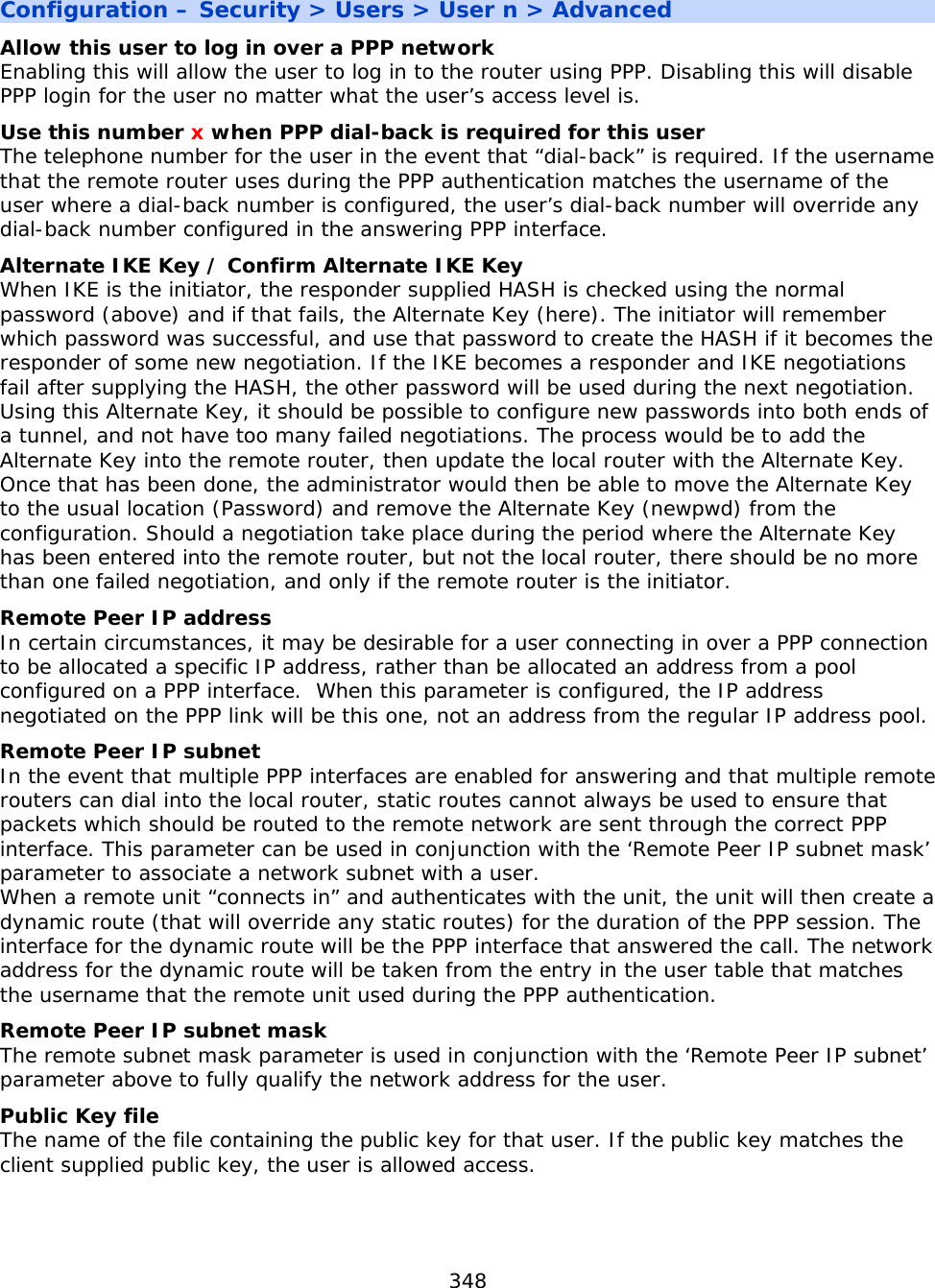
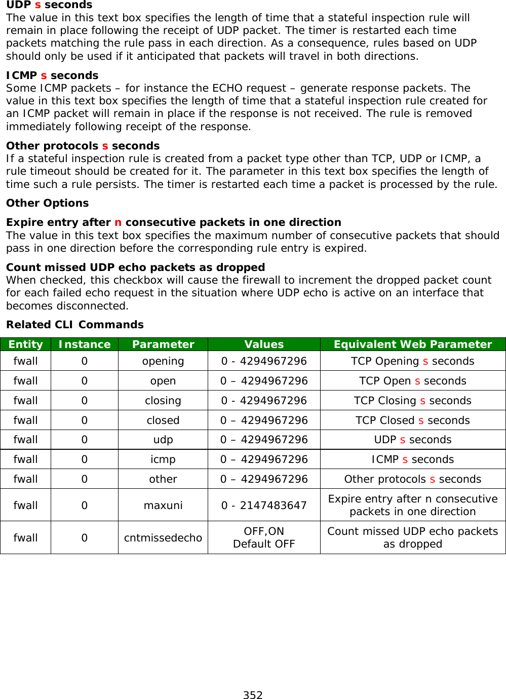
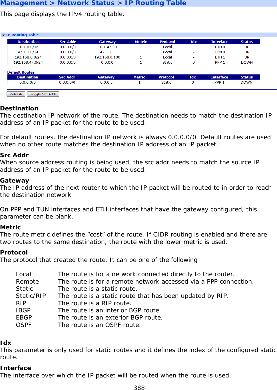
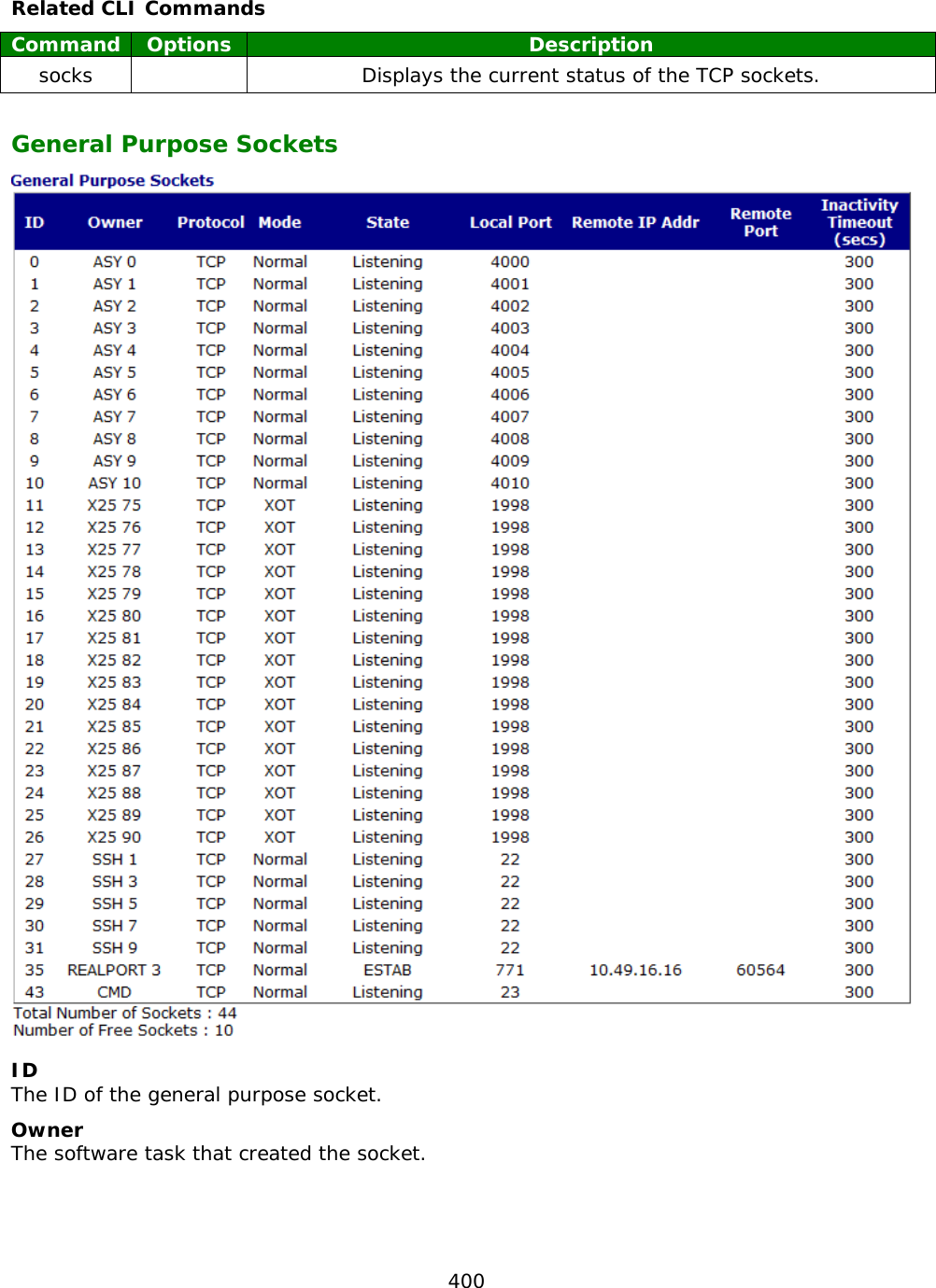
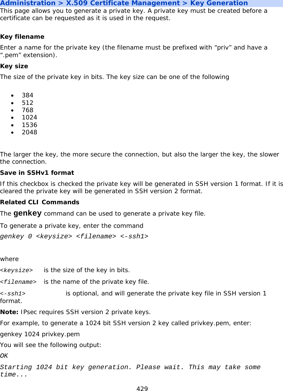
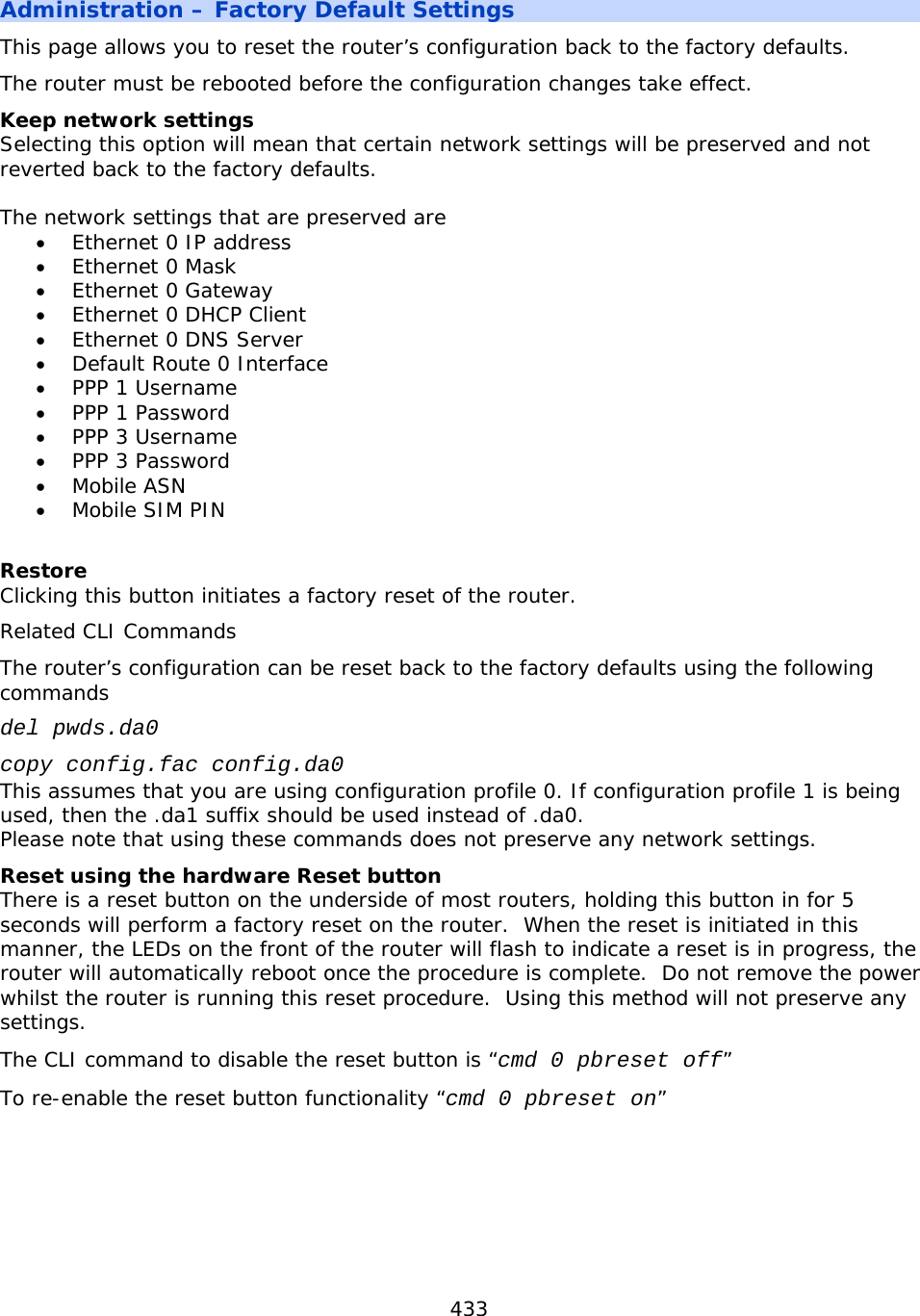
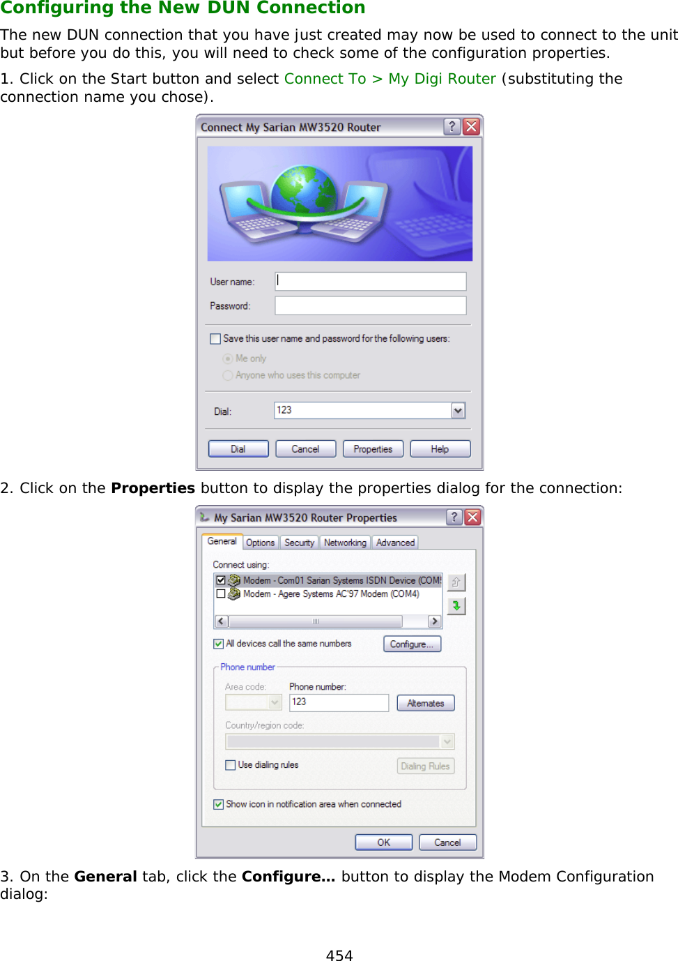
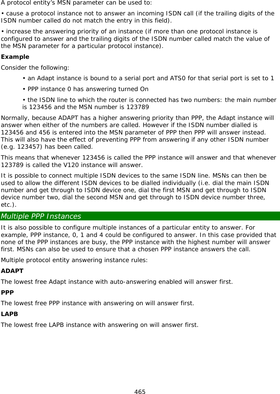
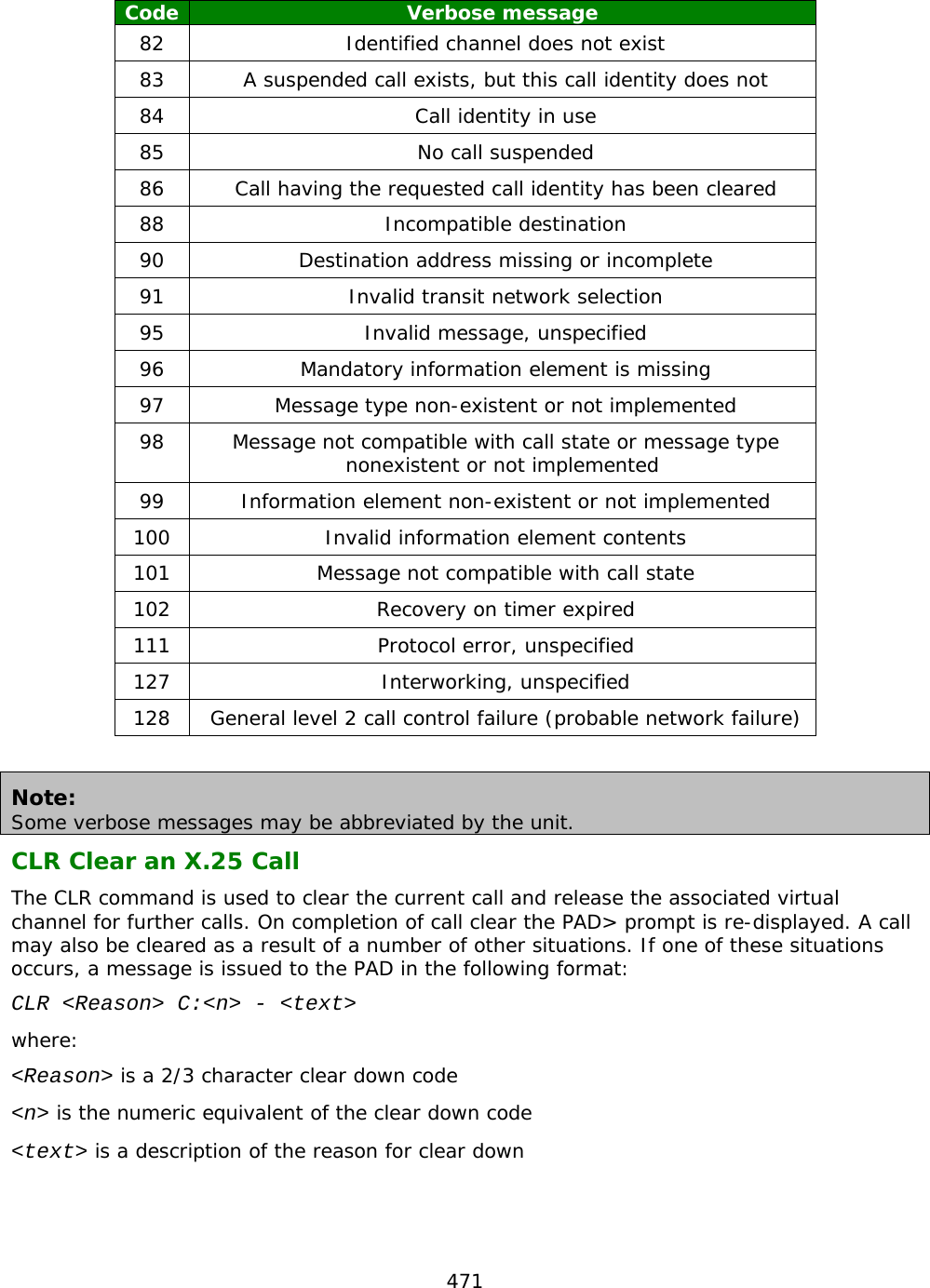
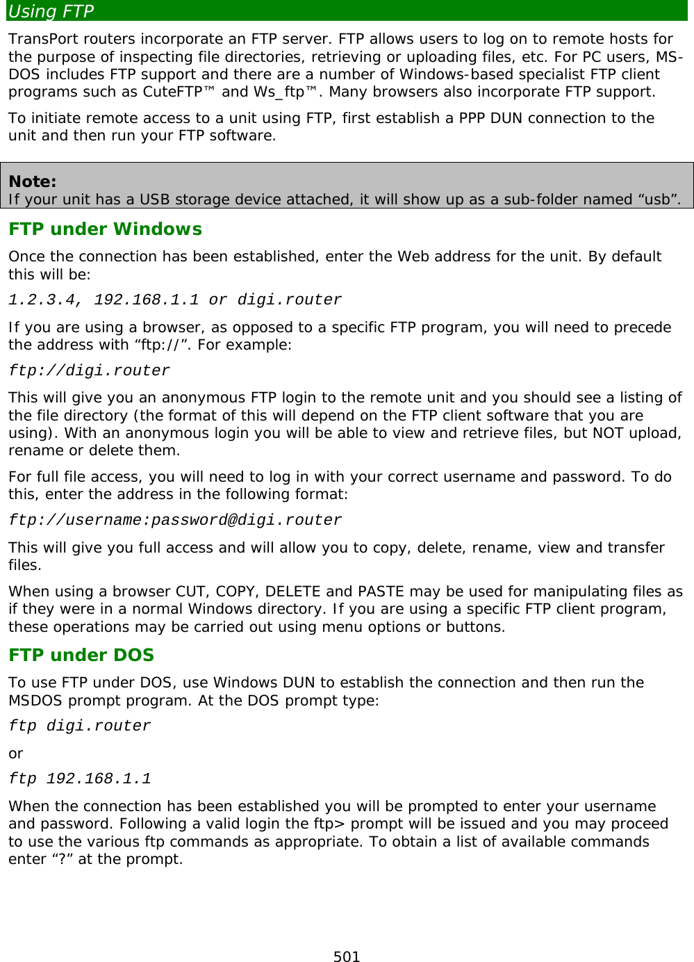
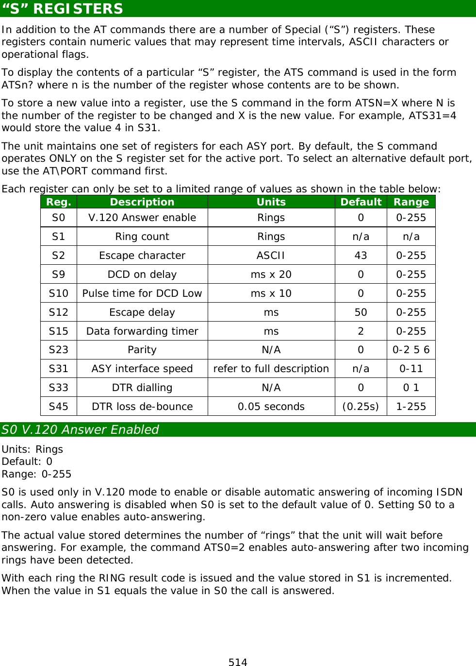
![171 Routing modes The TransPort has 2 routing modes available, these are: TransPort routing mode This is the original routing method and may be seen on existing installations. CIDR routing mode Now enabled by default on new TransPort routers. The CLI command to switch between the 2 modes is: ip 0 cidr [off|on] TransPort routing mode CIDR routing is disabled When the TransPort receives an IP packet to route, the routing table is used to decide through which interface to send the packet. Usually the destination IP address of the IP packet is compared with the IP Address and Mask of each entry in the routing table in index order regardless of the order in the routing table or length of mask. There may be more than one match and in this case the index number of the route is taken into account. The index number is simply the route number in the config, Static Route 0 or 1 is index 0 or 1 Static routes are checked first, then dynamic routes, then default routes. CLI command: ip 0 cidr off CIDR routing mode CIDR routing is enabled When the TransPort receives an IP packet to route, the routing table is used to decide through which interface to send the packet. Usually the destination IP address of the IP packet is compared with the IP Address and Mask of each entry in the routing table. There may be more than one match and in this case the most specific route is used to route the packet. Ie, a matching /24 route is used before a matching /16 route. If multiple routes match the destination and have the same prefix length, the index number of the routes in the routing table is used to determine the route. CLI command: ip 0 cidr on Route Metrics Route Metric settings can be set to override the order in which the routes are searched. Routes with lower metric numbers will always be used in preference to routes with higher metric numbers even if the routes with higher metric numbers appear first in the routing table. Route metrics can be configured by means of the route parameters: Connected Metric Disconnected Metric](https://usermanual.wiki/Digi/55M1644B.Manual-pt-1/User-Guide-1821845-Page-171.png)
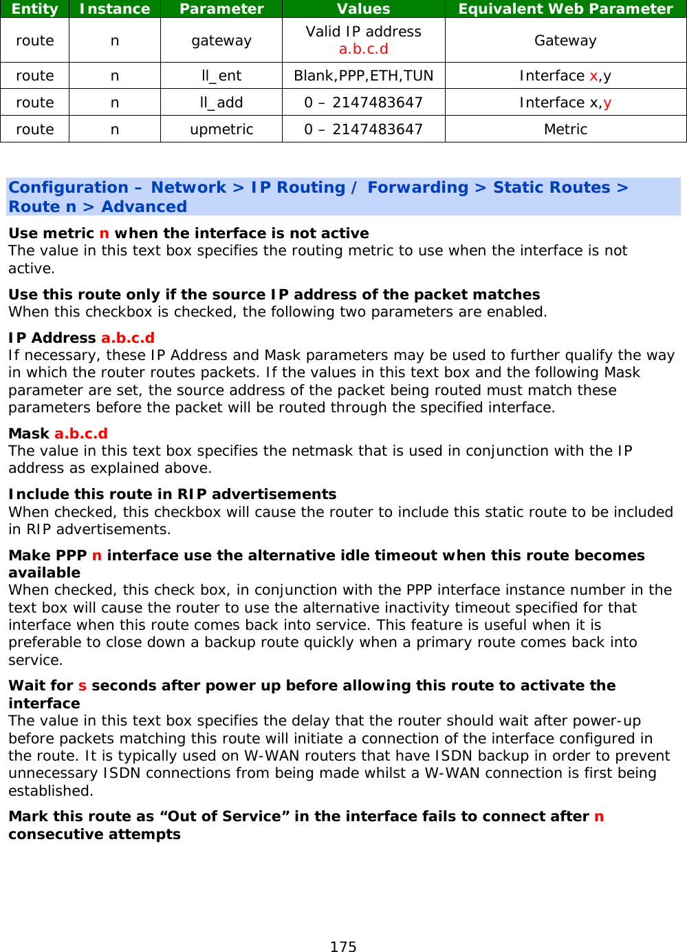
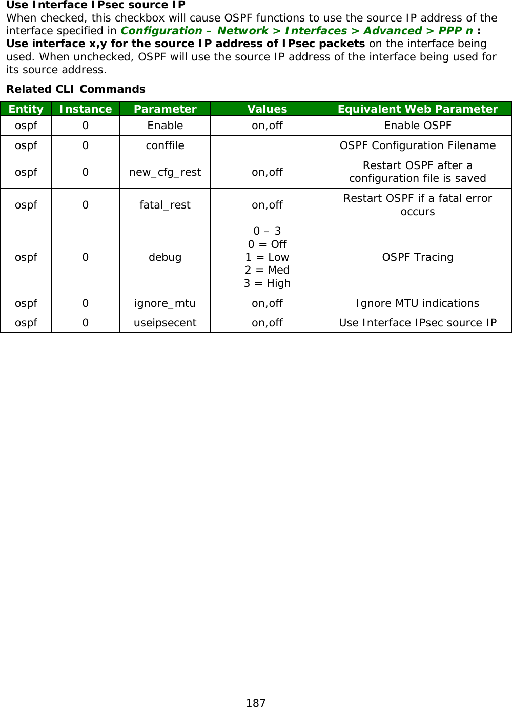
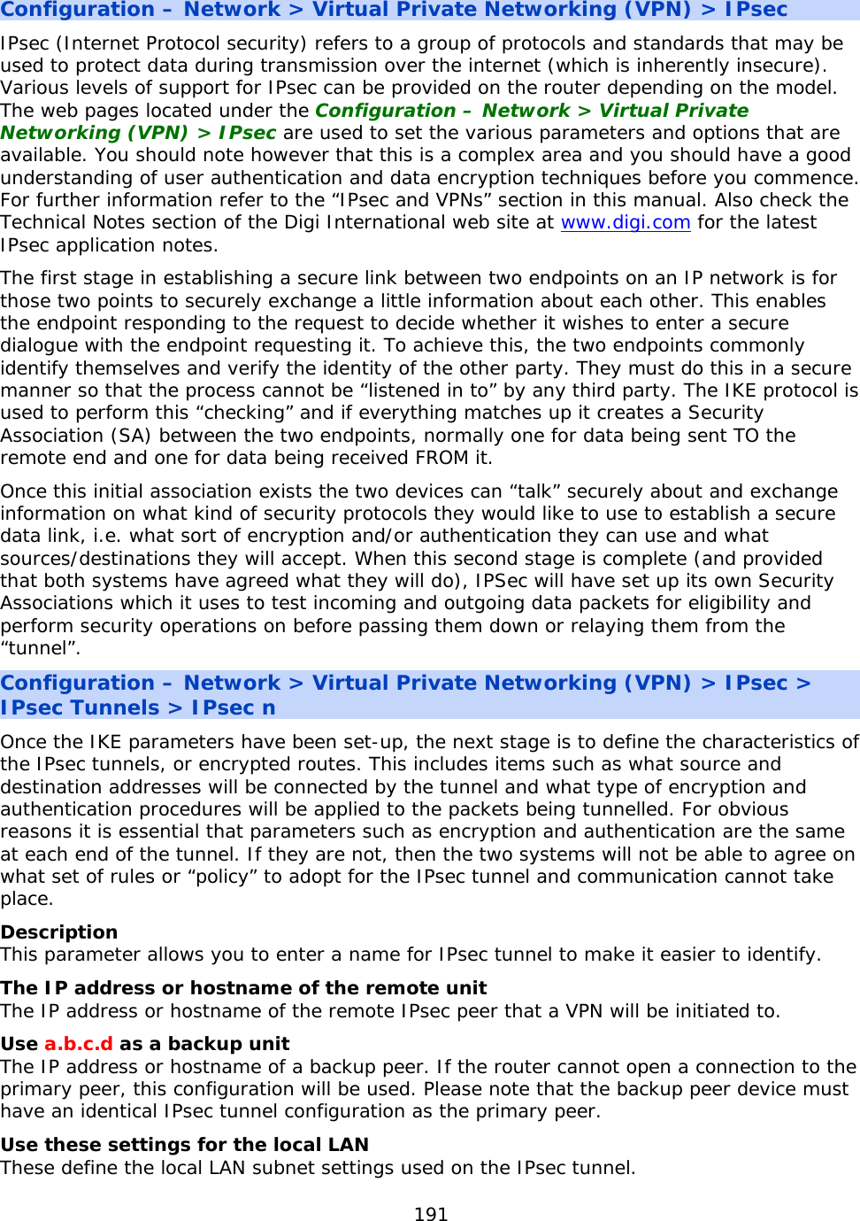
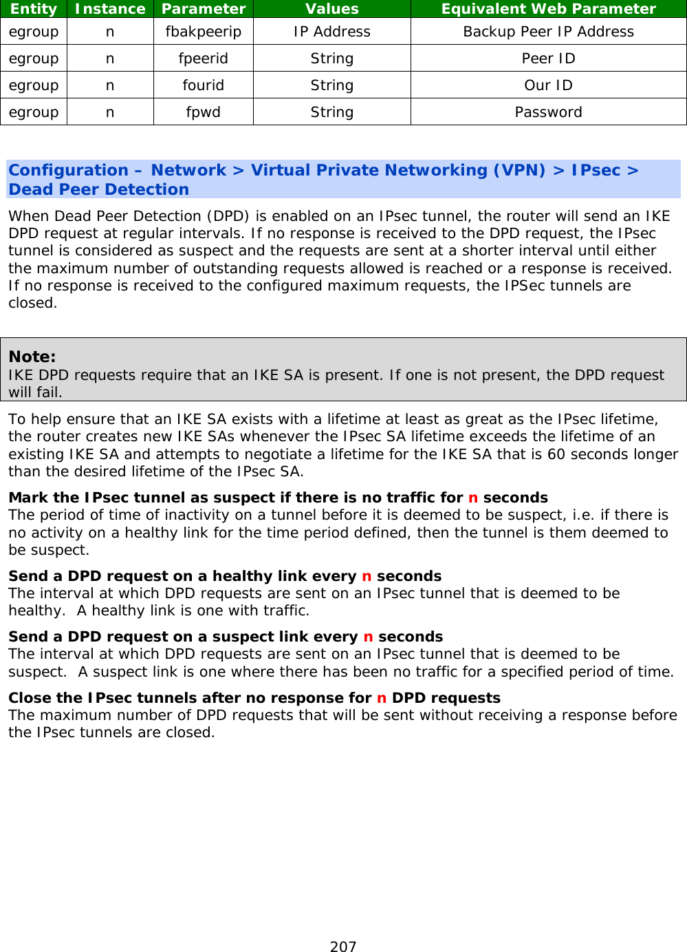
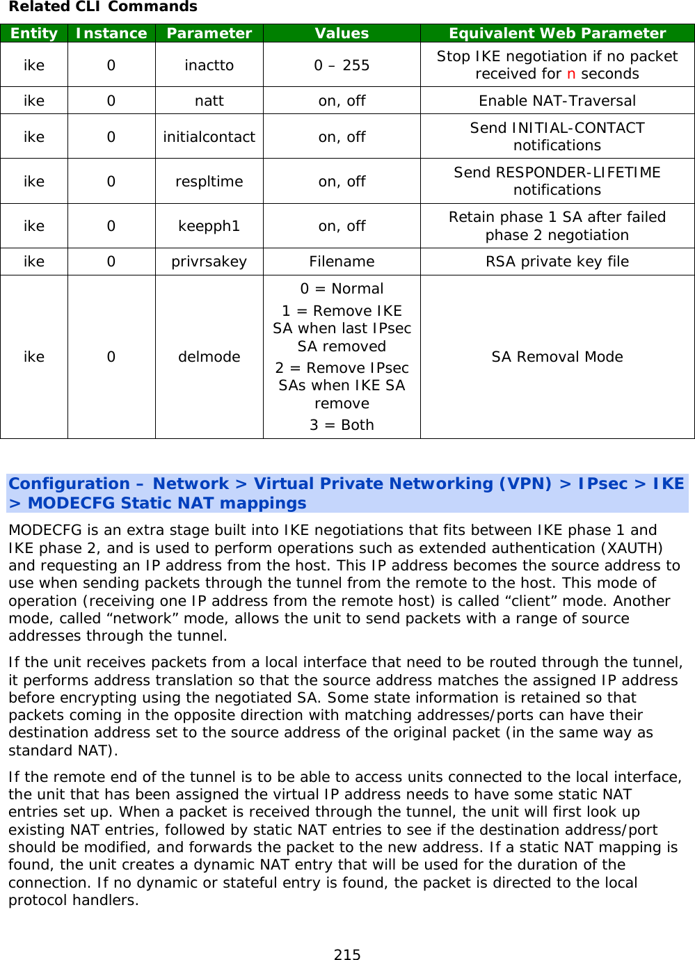
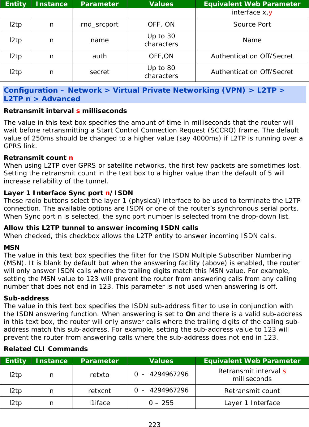
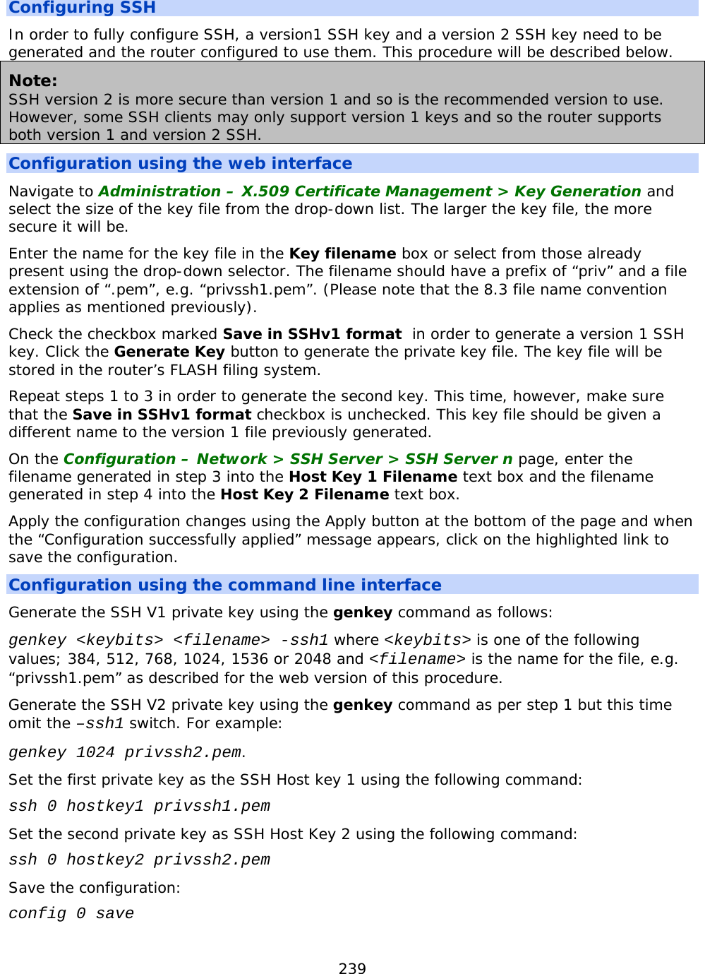
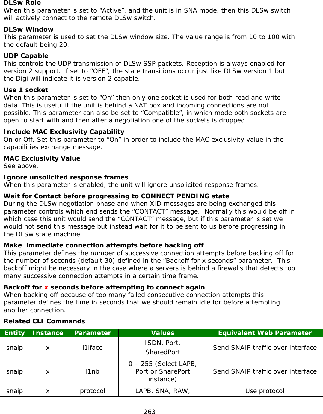
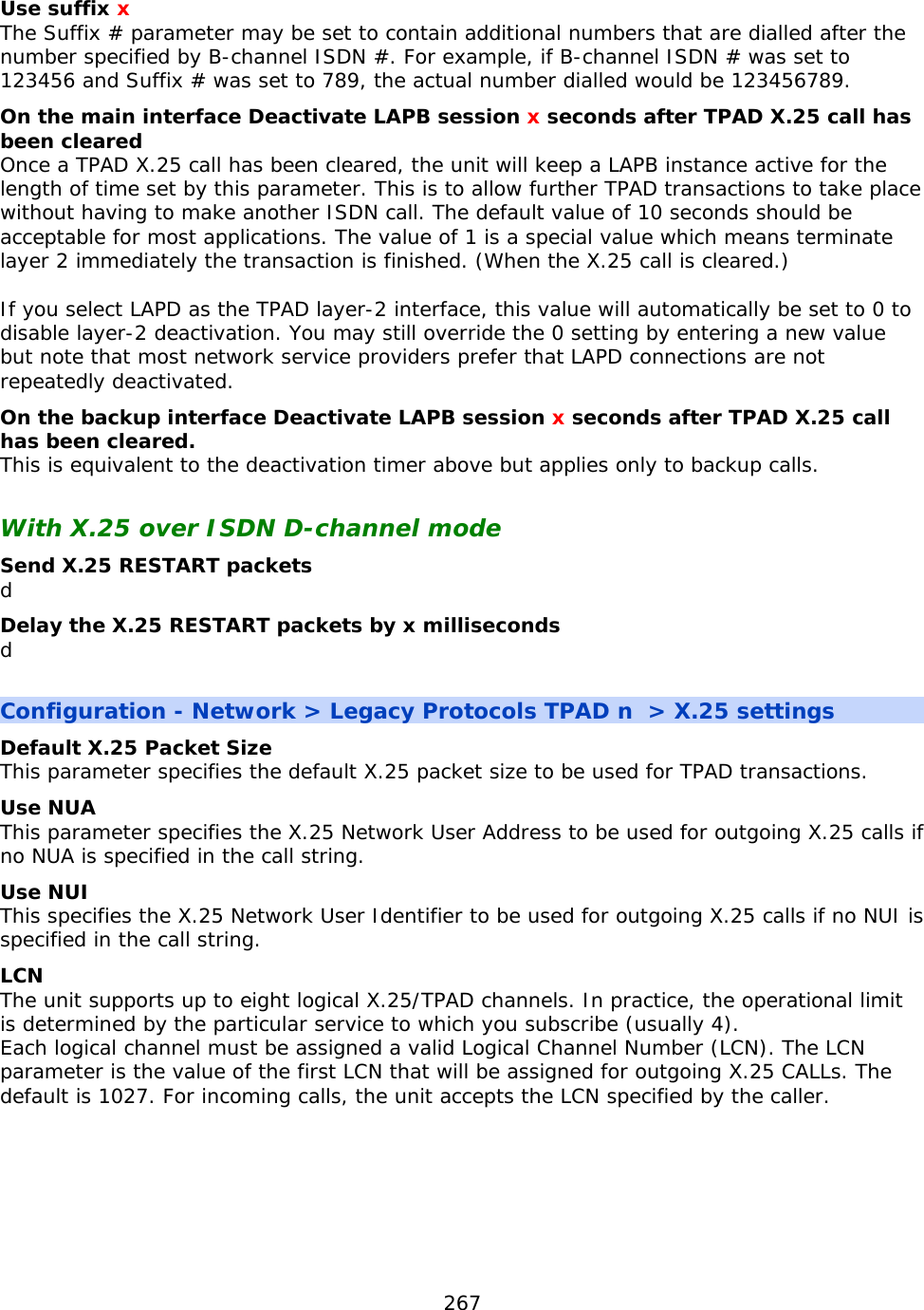
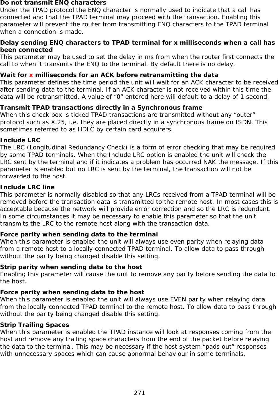
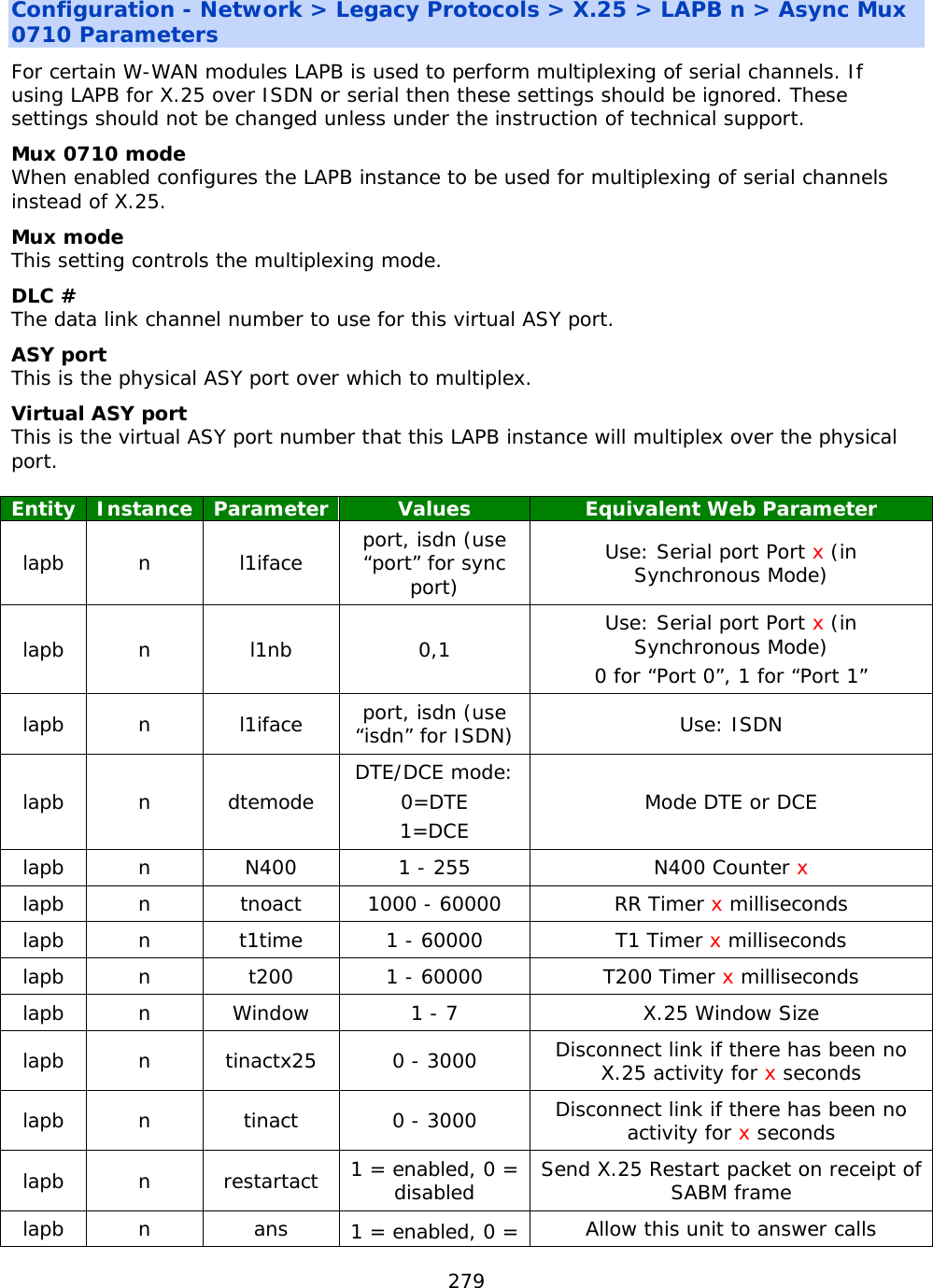
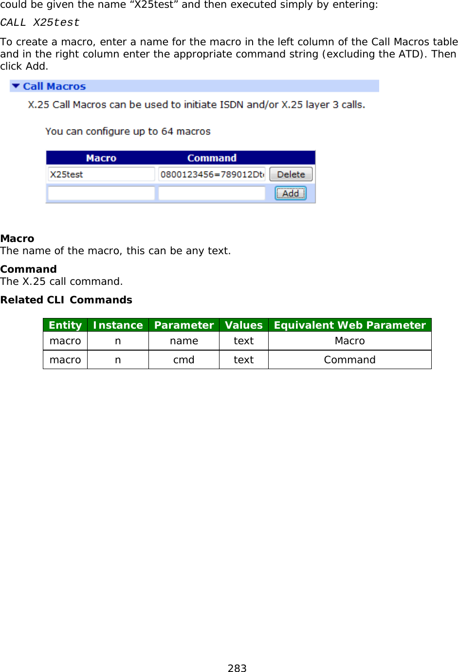
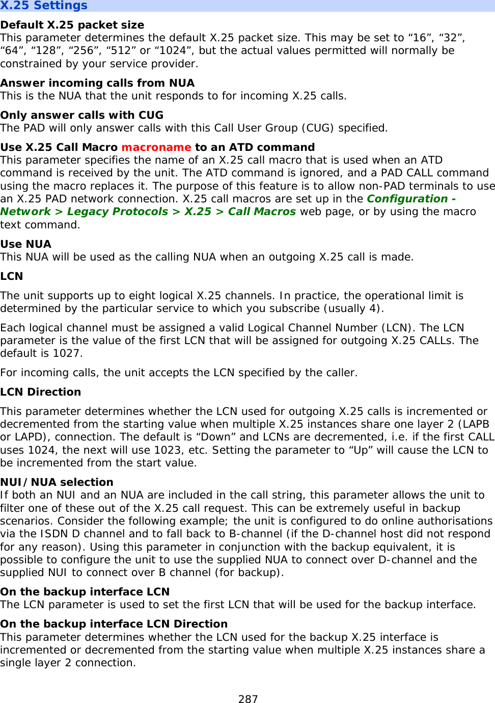
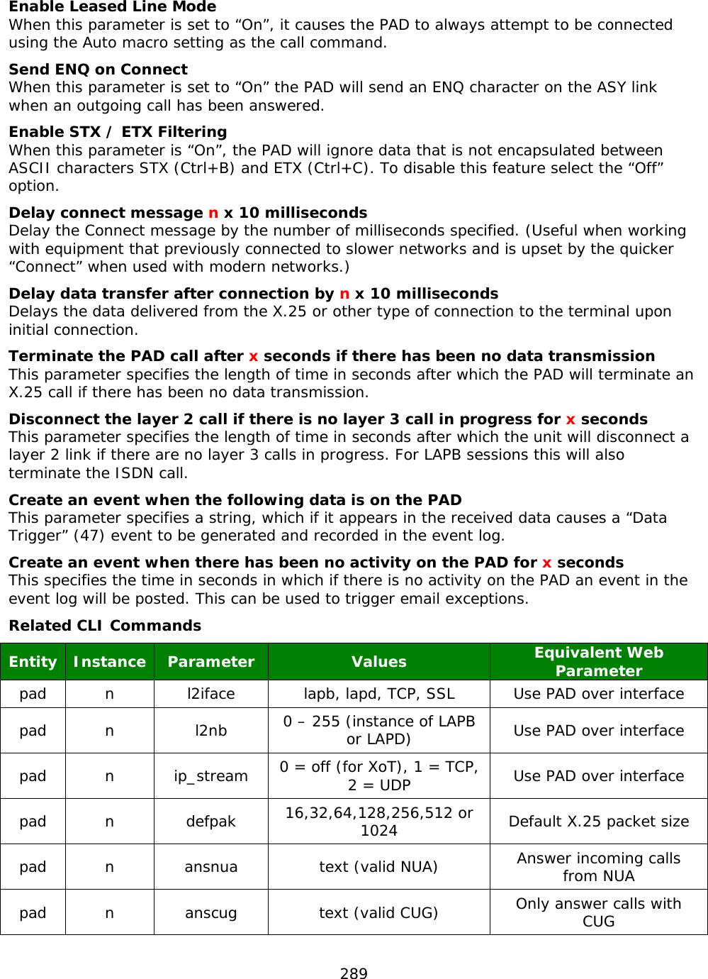
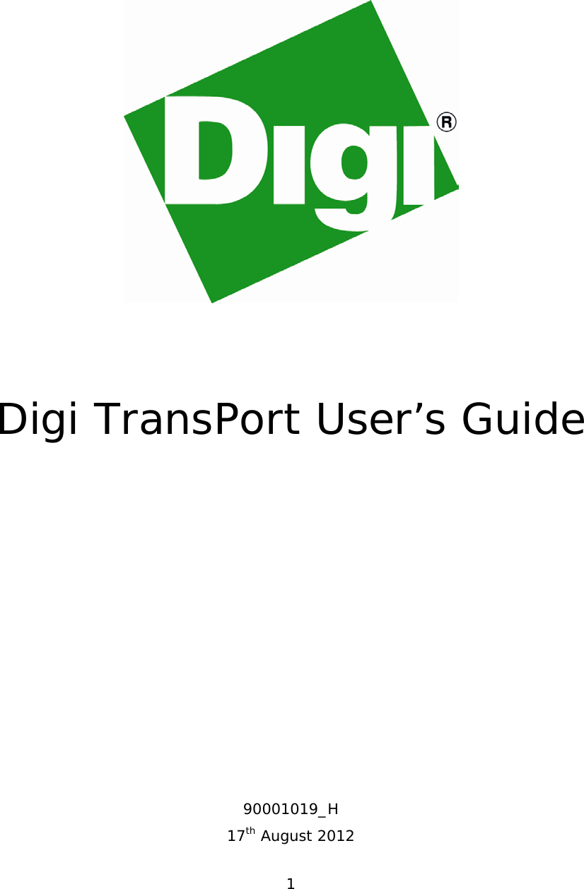
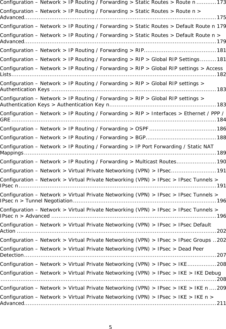
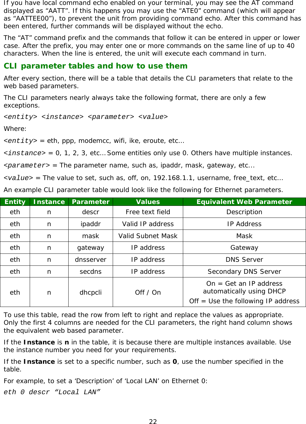
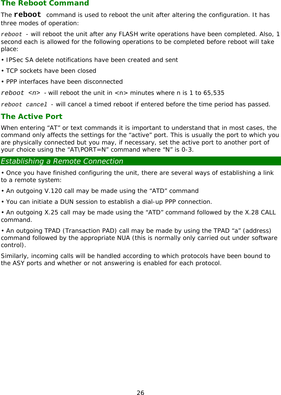
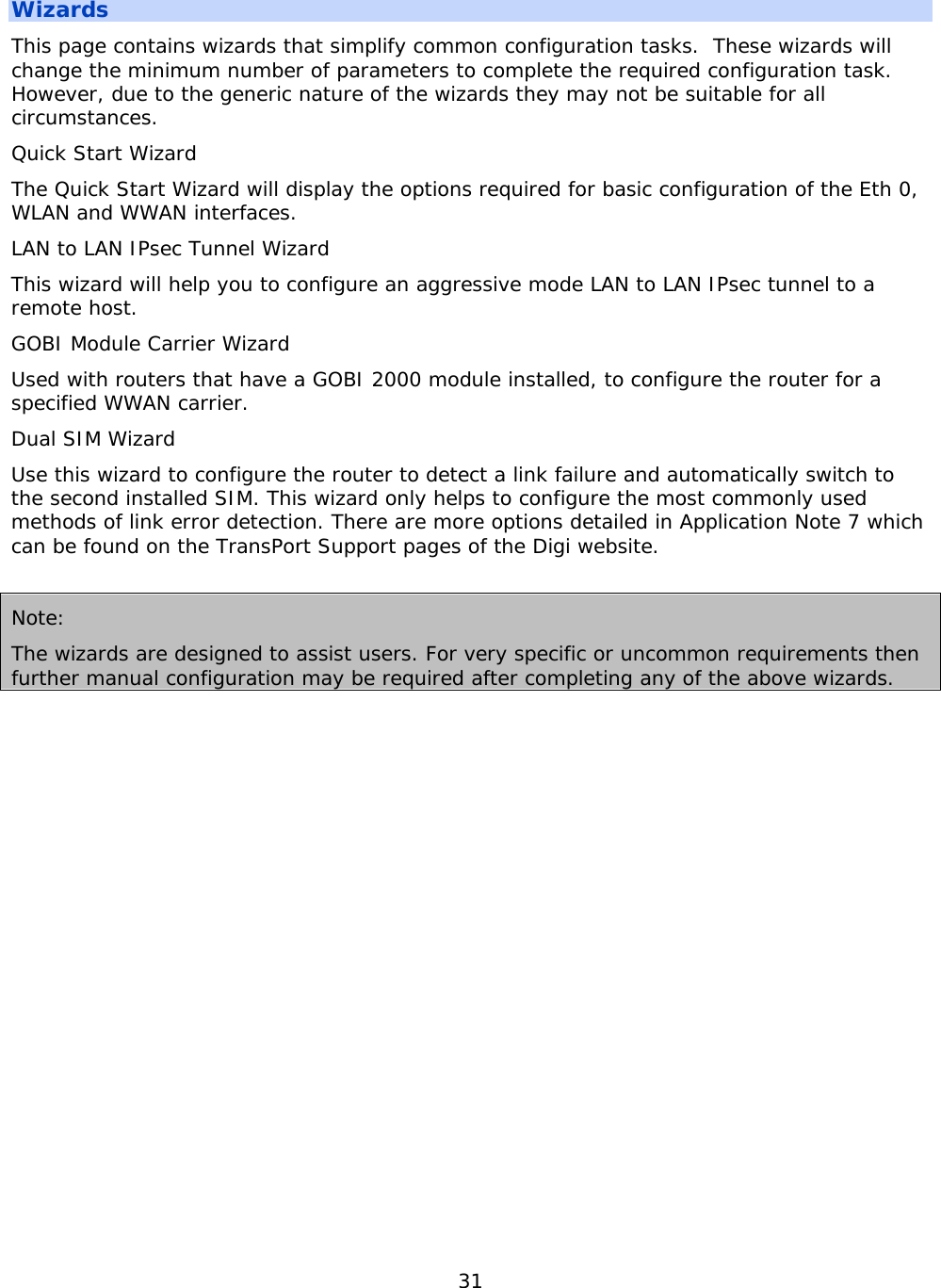
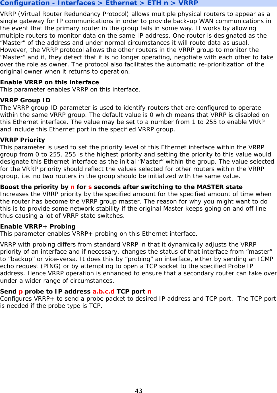
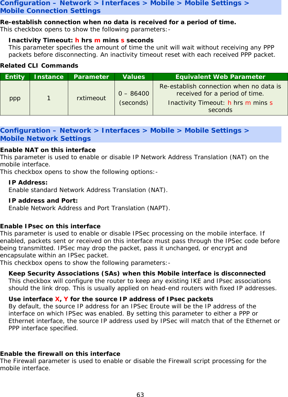
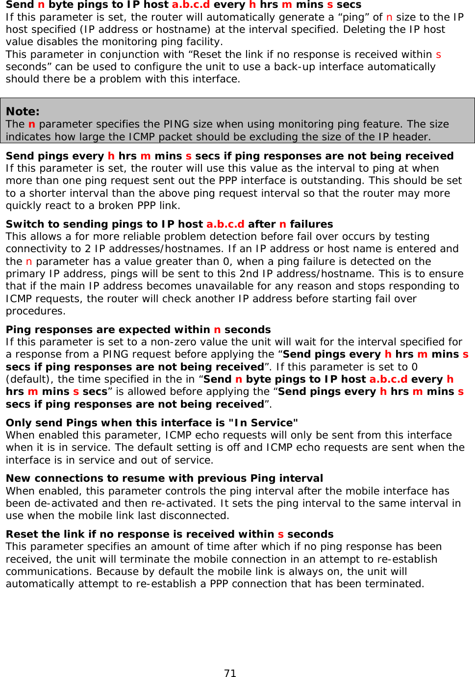
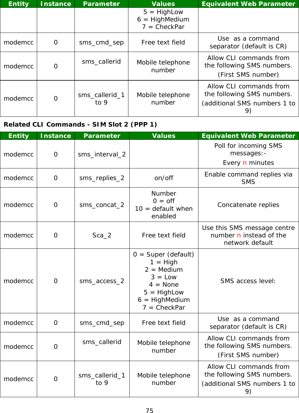
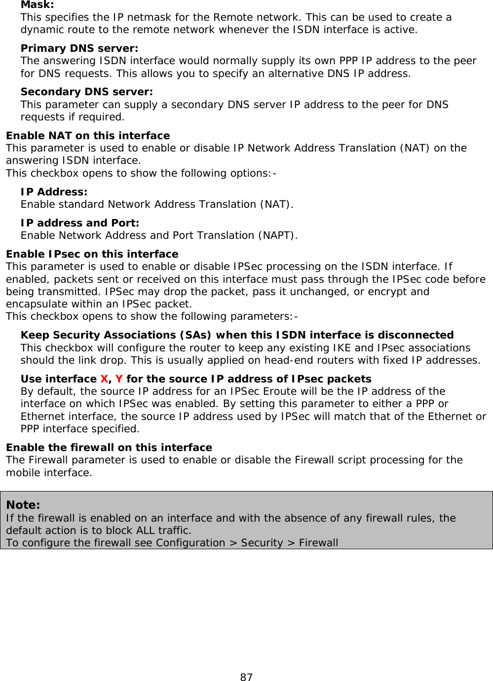
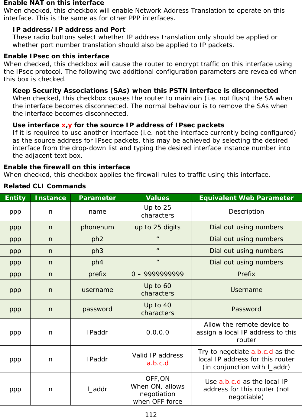
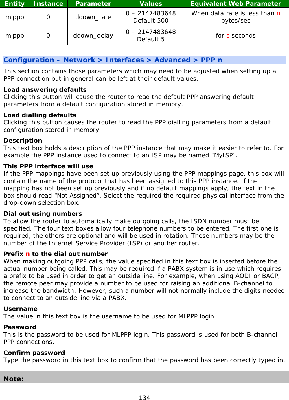
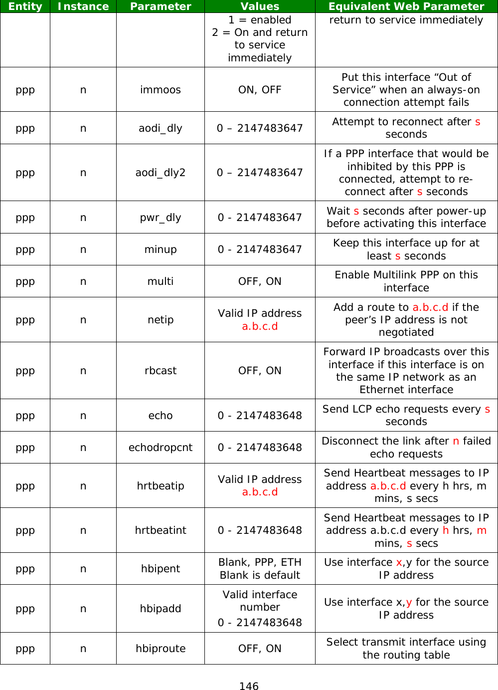
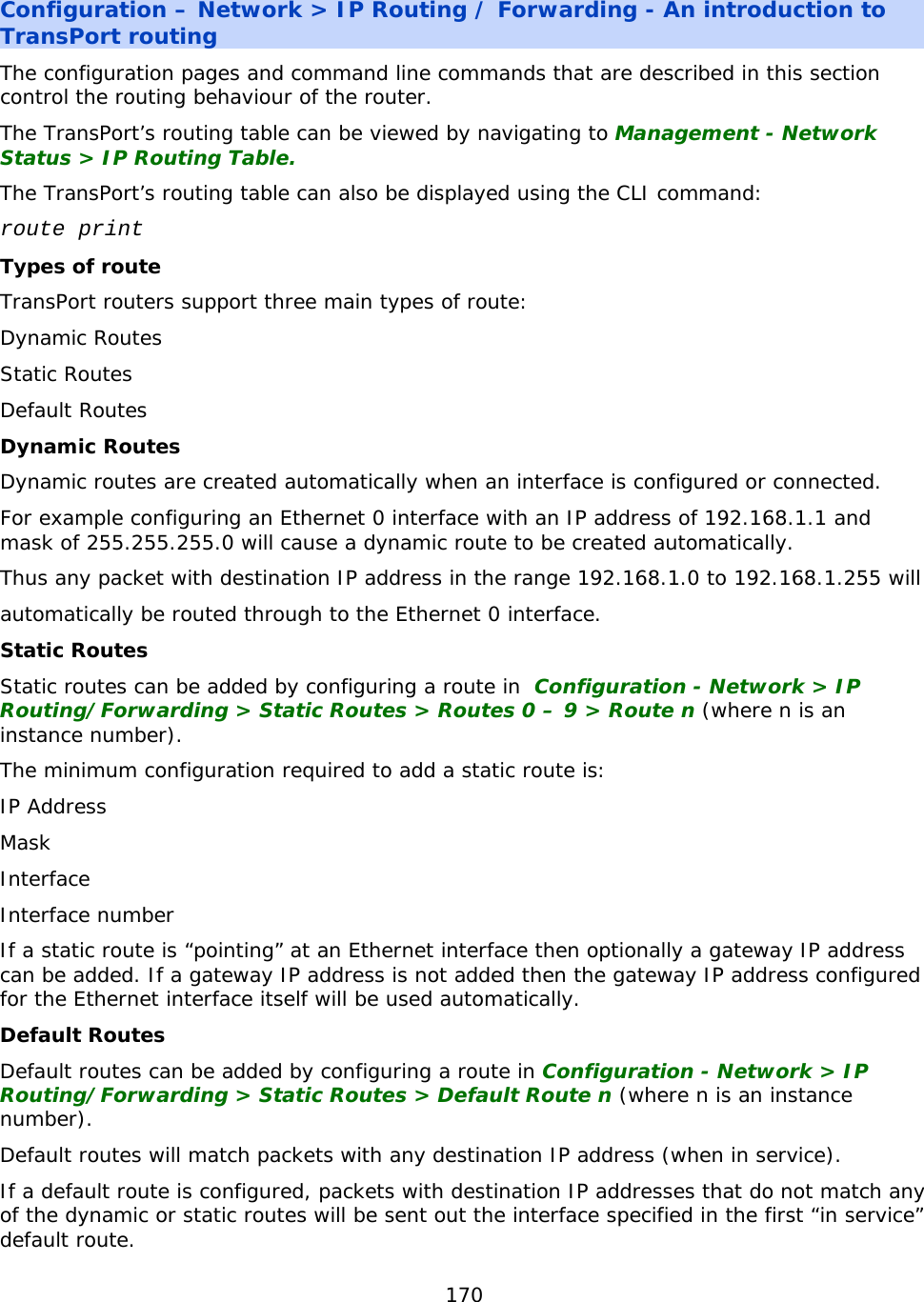
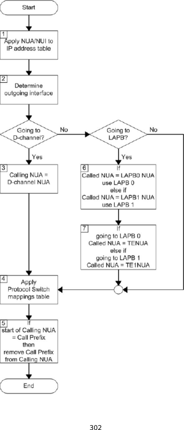
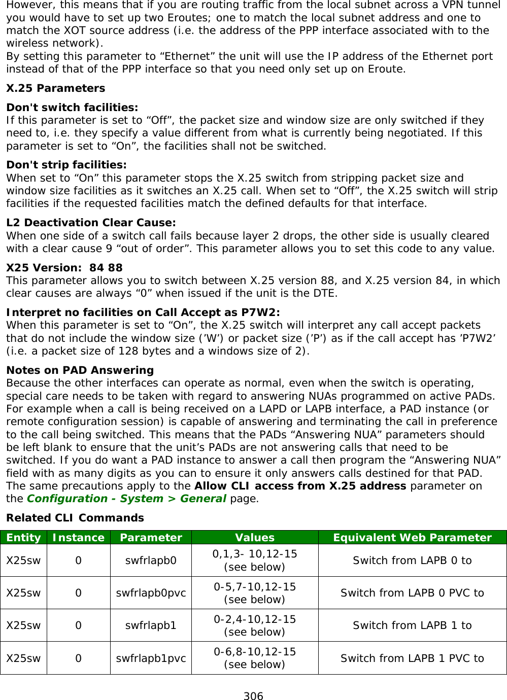
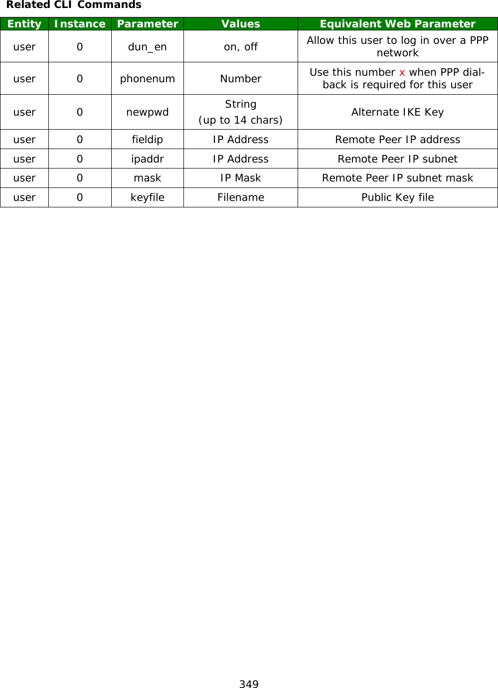
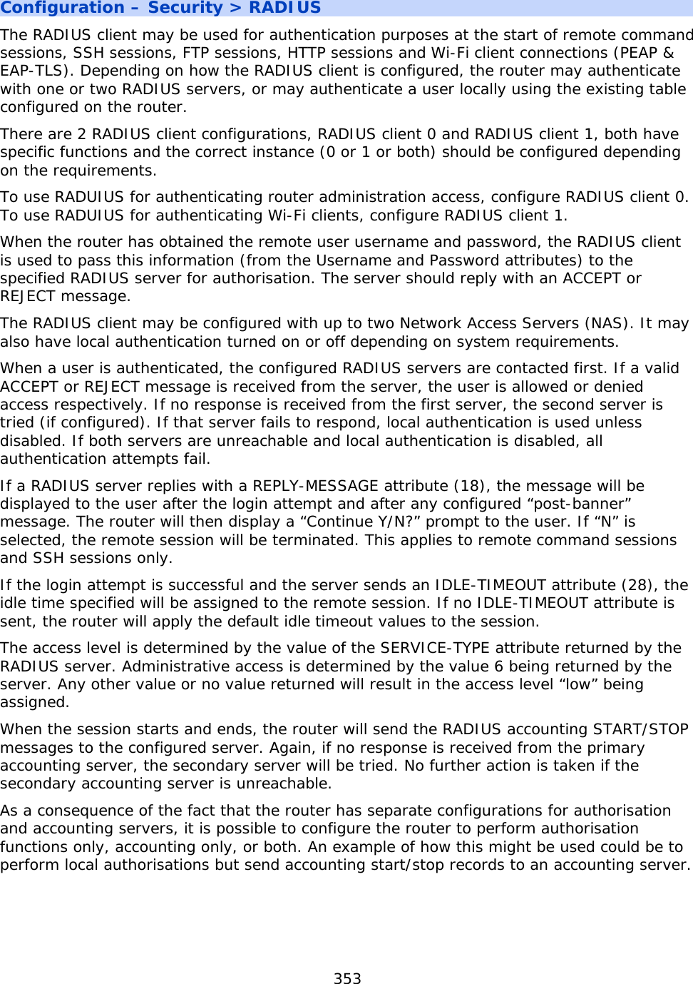
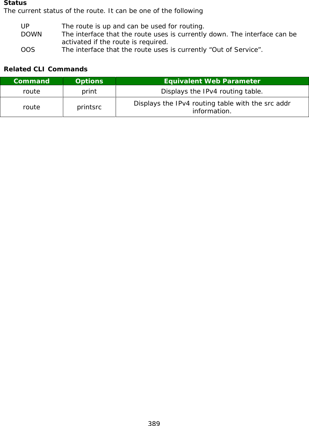
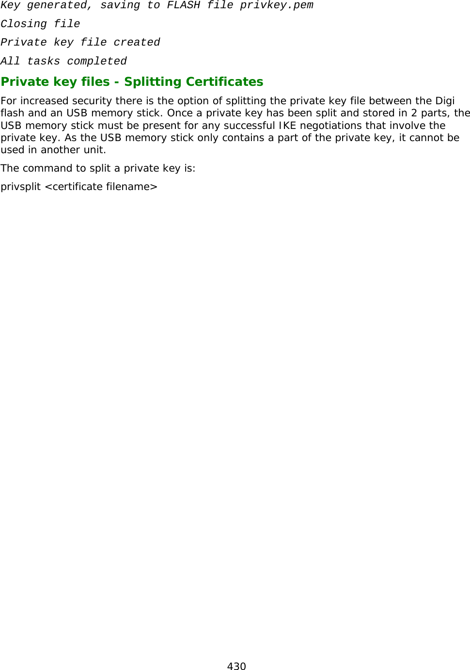
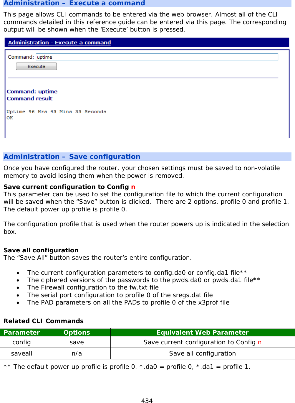
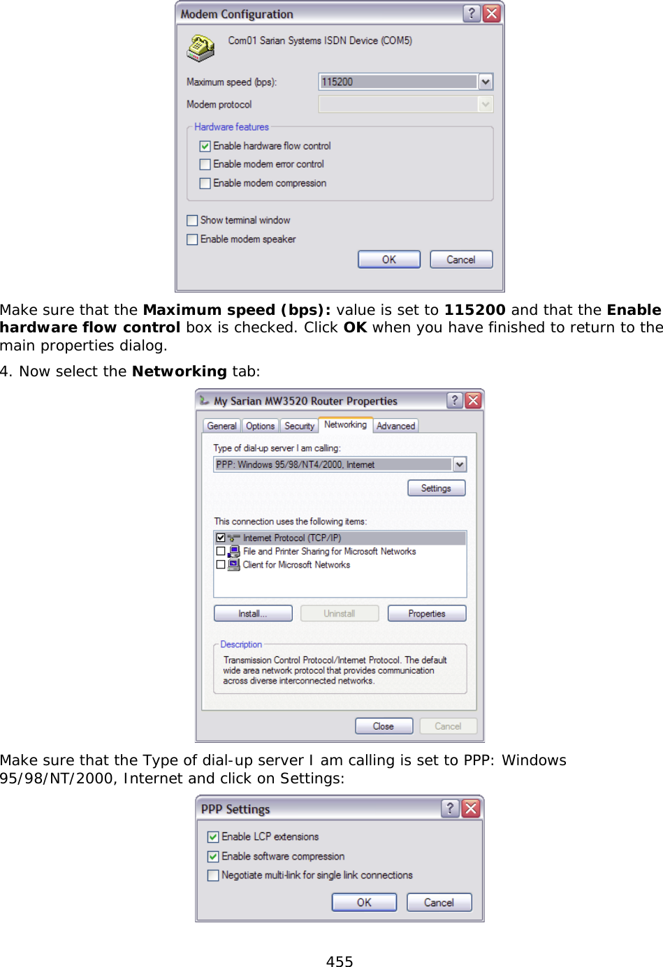
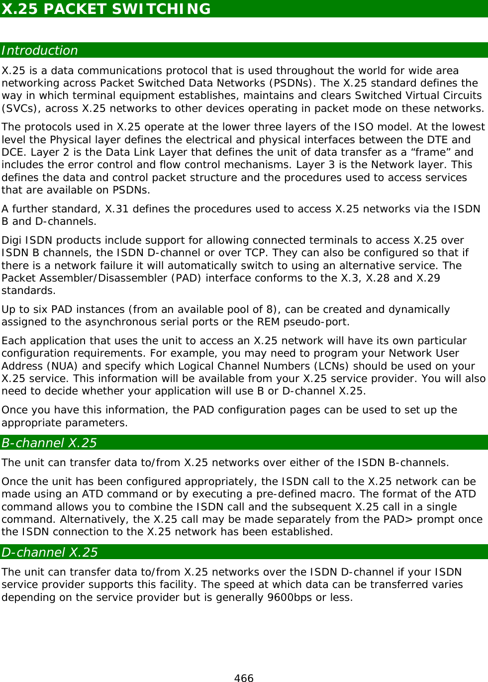
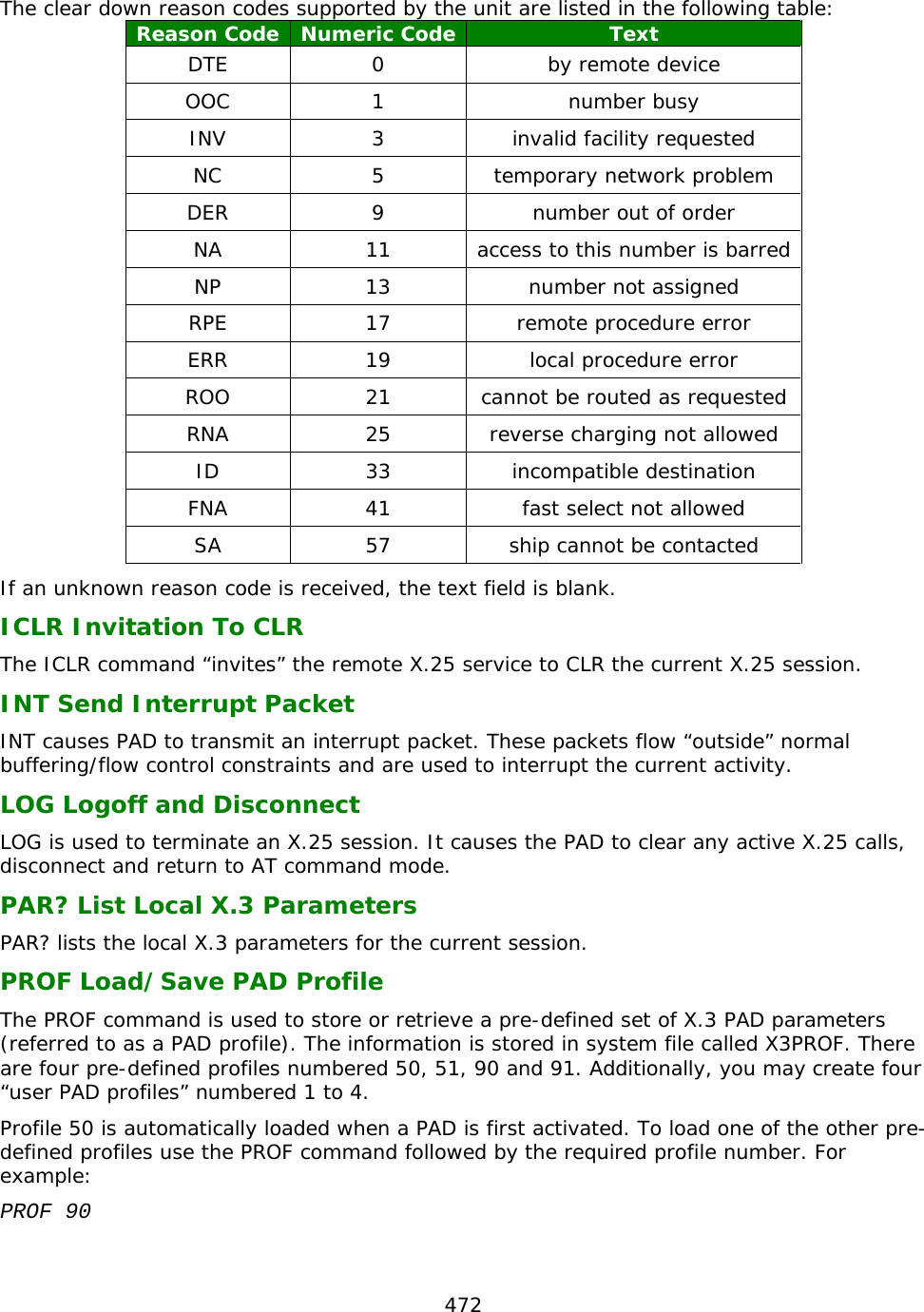
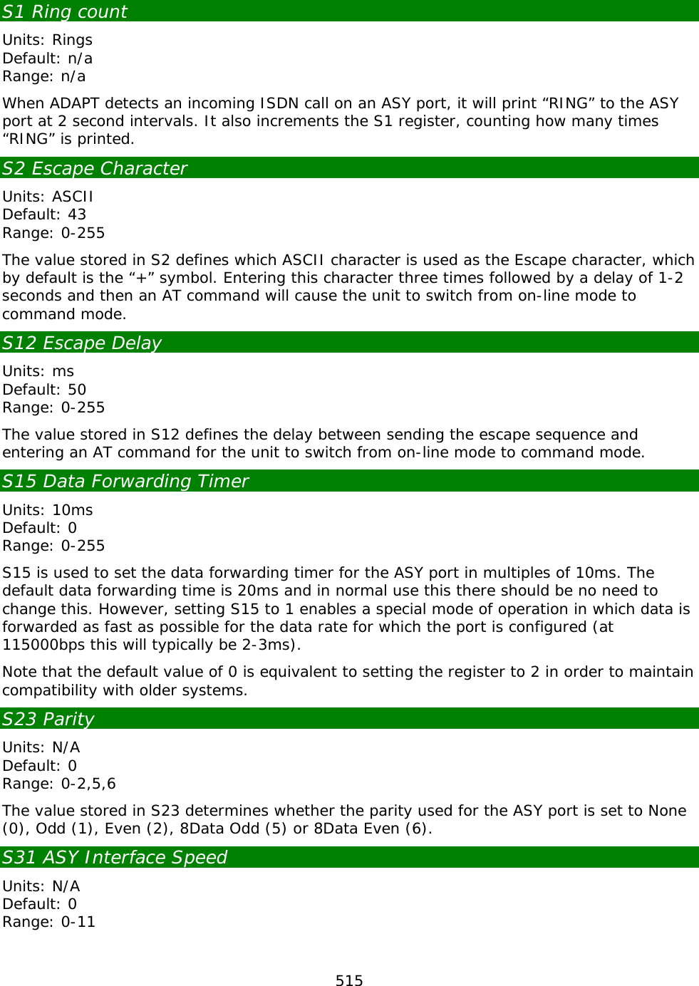
![291 Entity Instance Parameter Values Equivalent Web Parameter PAD pad n inactevent 0 - 2147483647 Create an event when there has been no activity on the PAD for x seconds Stopping and starting PADs PAD instances can be stopped and started using the following CLI commands: stoppads gopads The stoppads command stops all PAD instances from accepting and performing any PAD commands. The gopads command resumes processing of PAD commands. The stoppads and gopads commands can have the PAD number specified in the syntax to stop and start individual PAD instances. For example: To stop PAD 1 from processing PAD commands: stoppads 1 and to re-enable PAD 1: gopads 1 Configuration - Network > Legacy Protocols > X.25 > PADs 0-9 > PAD 0 > X3 Parameters Each PAD configuration page has an attached sub-page that allows you to edit the X.3 PAD parameters. These pages allow you to load one of the standard profiles or edit the individual parameters to suit your application requirements and save the resulting customised “user” profile to non-volatile memory. Loading and Saving PAD Profiles To create your own PAD profiles, edit the appropriate parameters and then select user profile 1, 2, 3 or 4 as required from the list and click the “Save Profile” button. Each PAD profile page includes two list boxes that allow you to load and save PAD profiles. To load a particular profile, select the profile from the list and click the “Load Profile” button. The parameter table will be updated with the values from the selected profile. 1 PAD Recall Character This parameter determines whether PAD recall is enabled. When this facility is enabled, typing the PAD recall character temporarily interrupts the call and returns you to the PAD> prompt where you may enter normal PAD commands as required. To resume the interrupted call, use the CALL command without a parameter. The default PAD recall character is [Ctrl-P]. This may be changed to any ASCII value in the range 32-125 or disabled by setting it to 0.](https://usermanual.wiki/Digi/55M1644B.Manual-pt-1/User-Guide-1821845-Page-291.png)
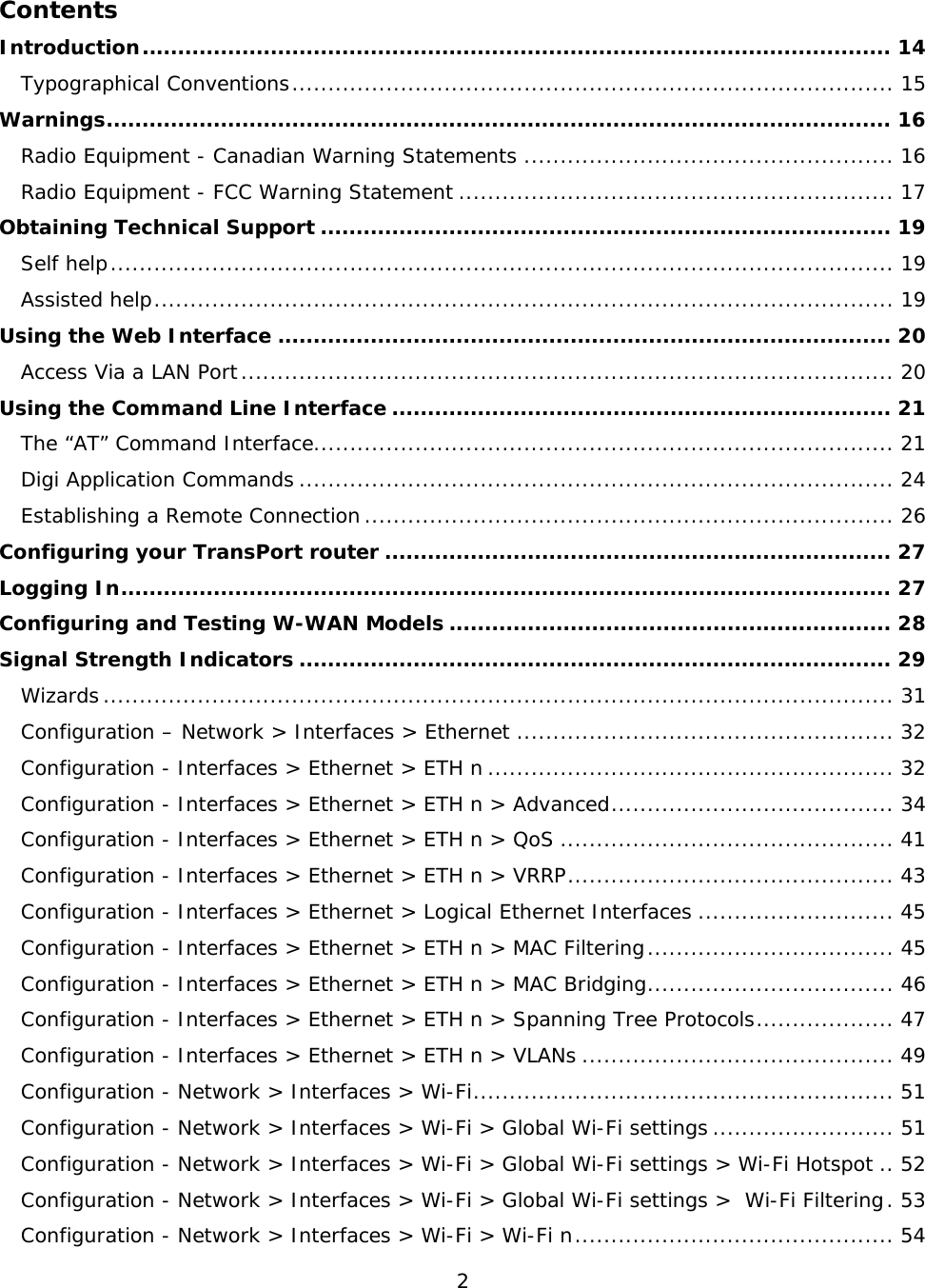
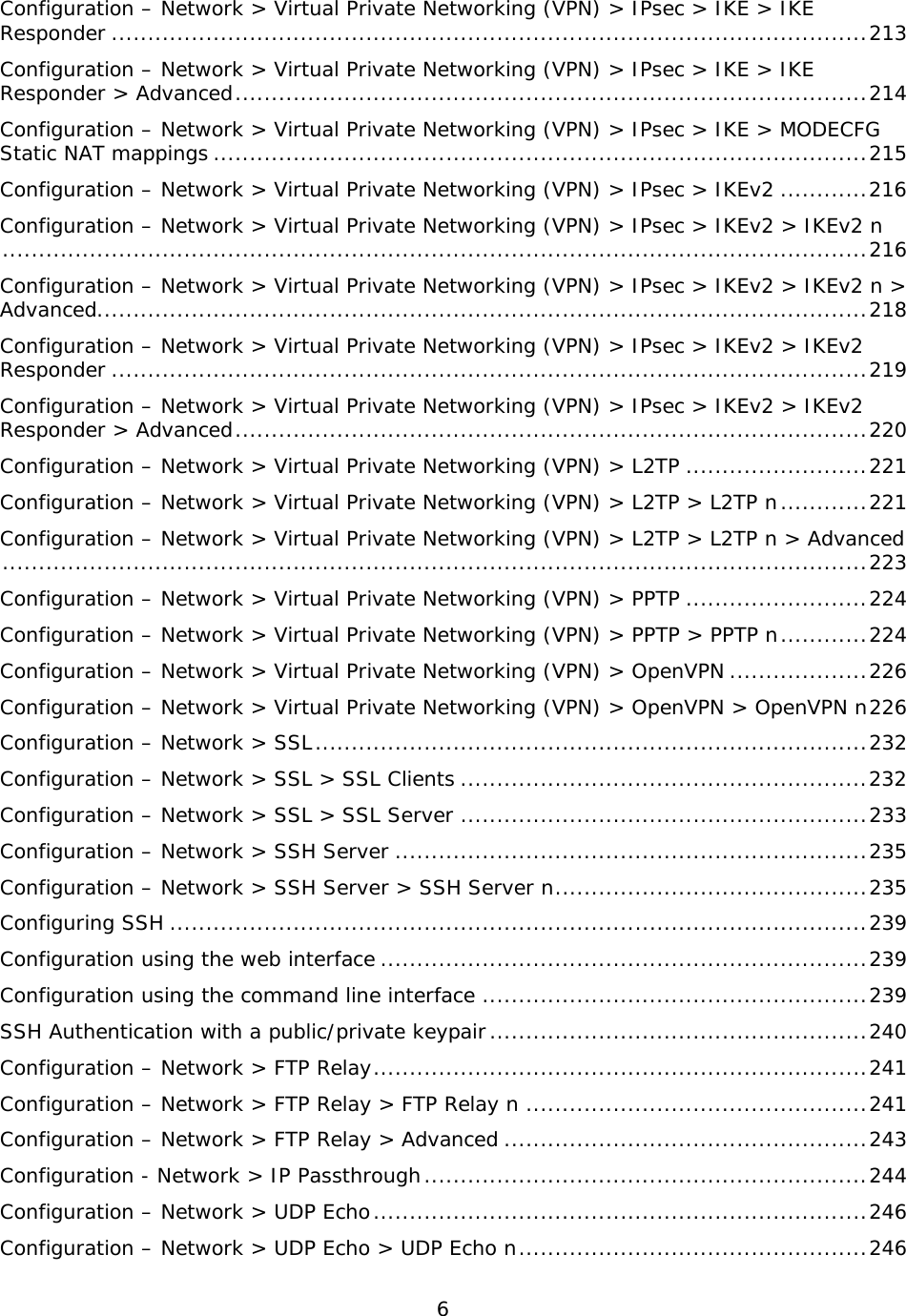
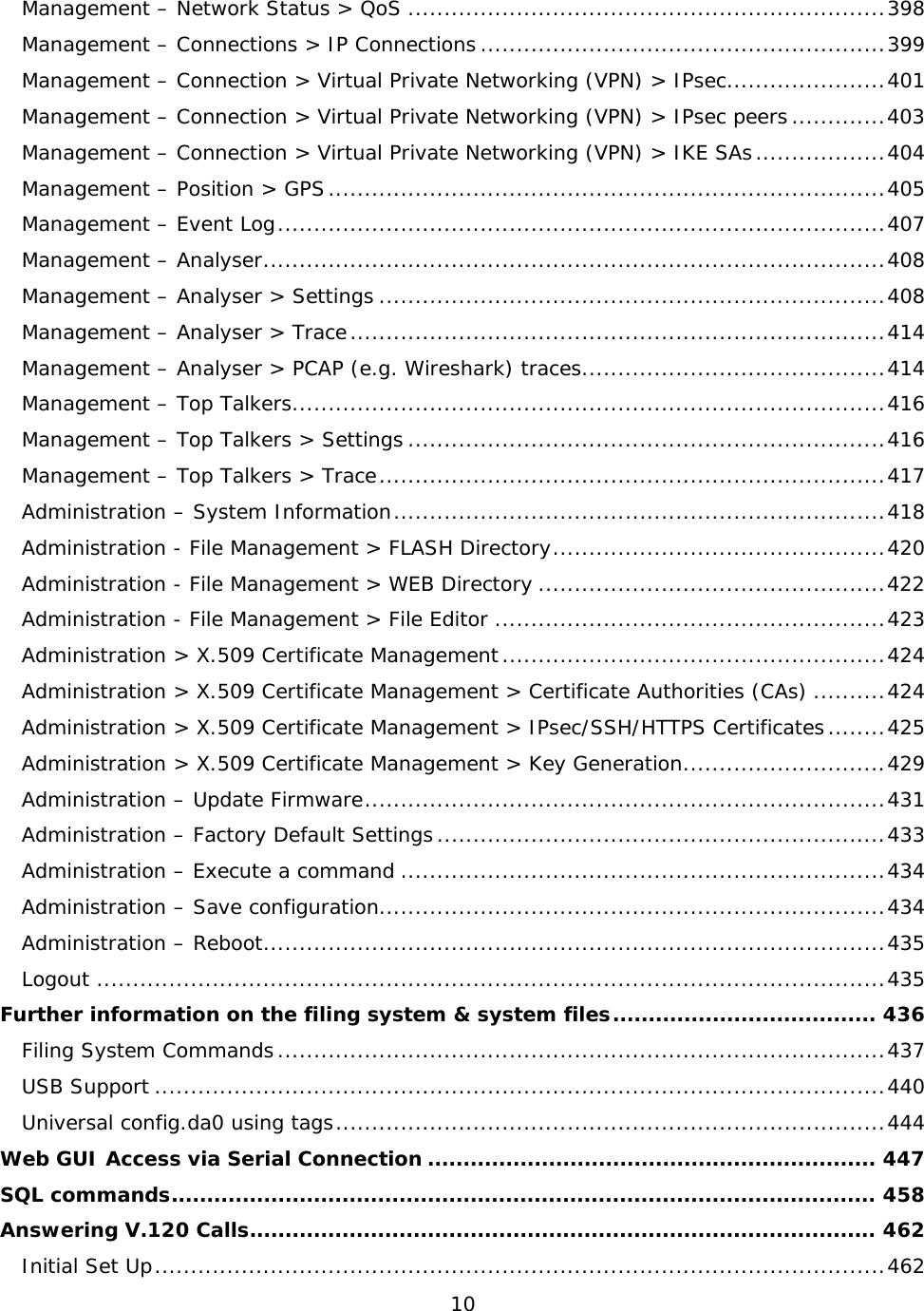
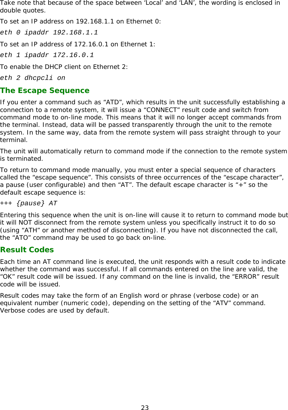
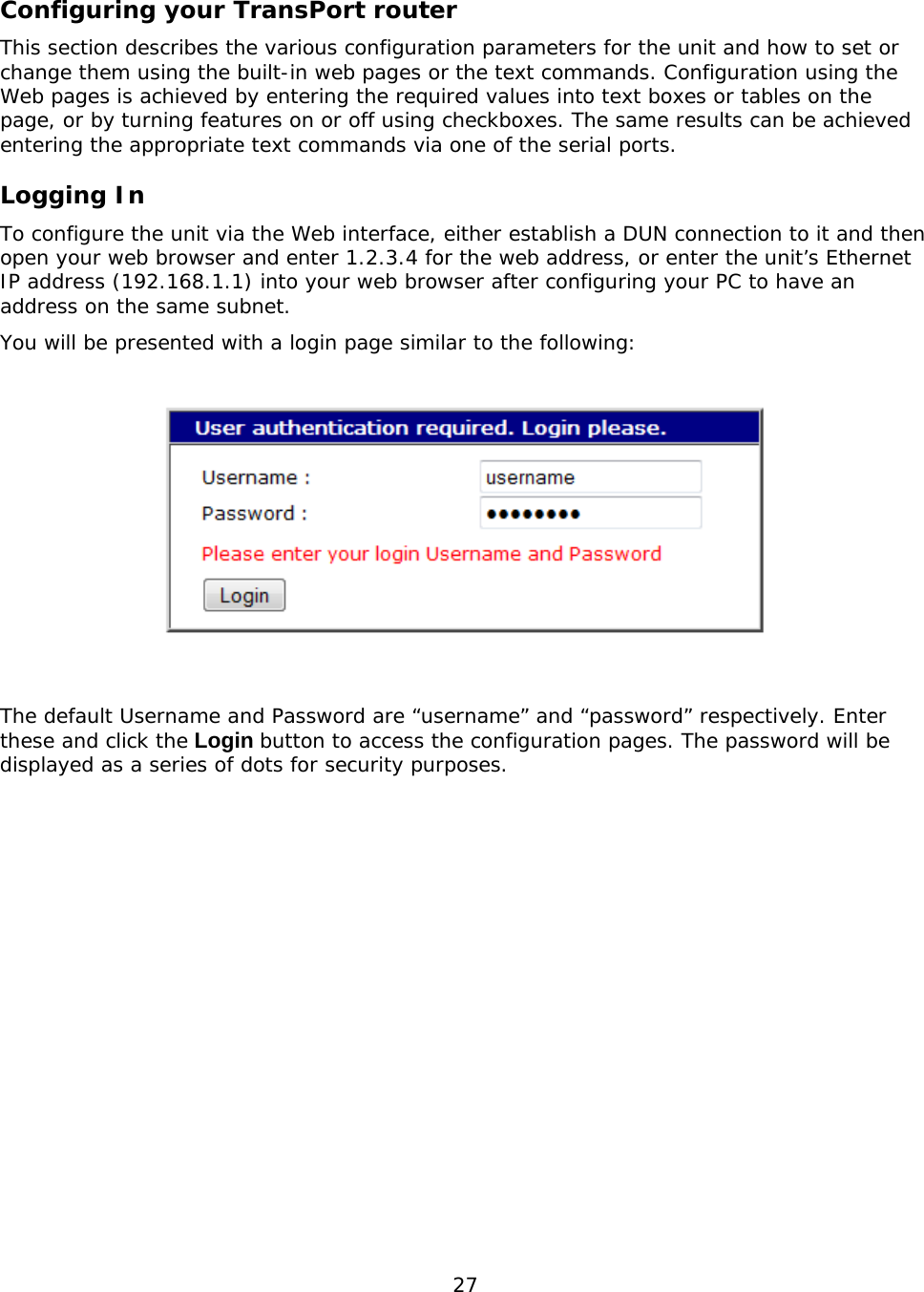
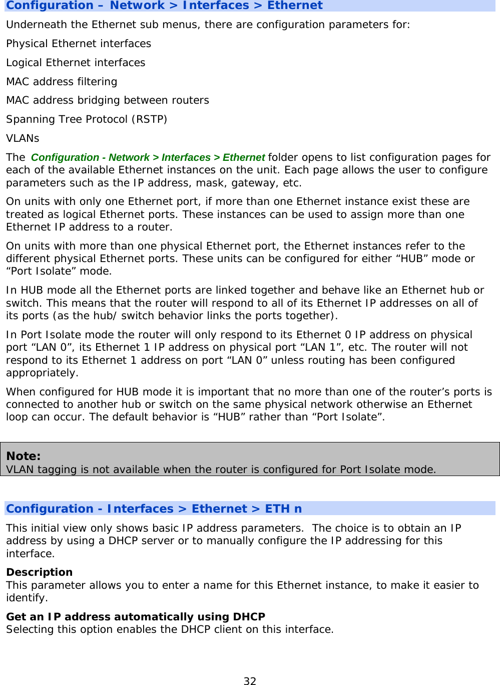
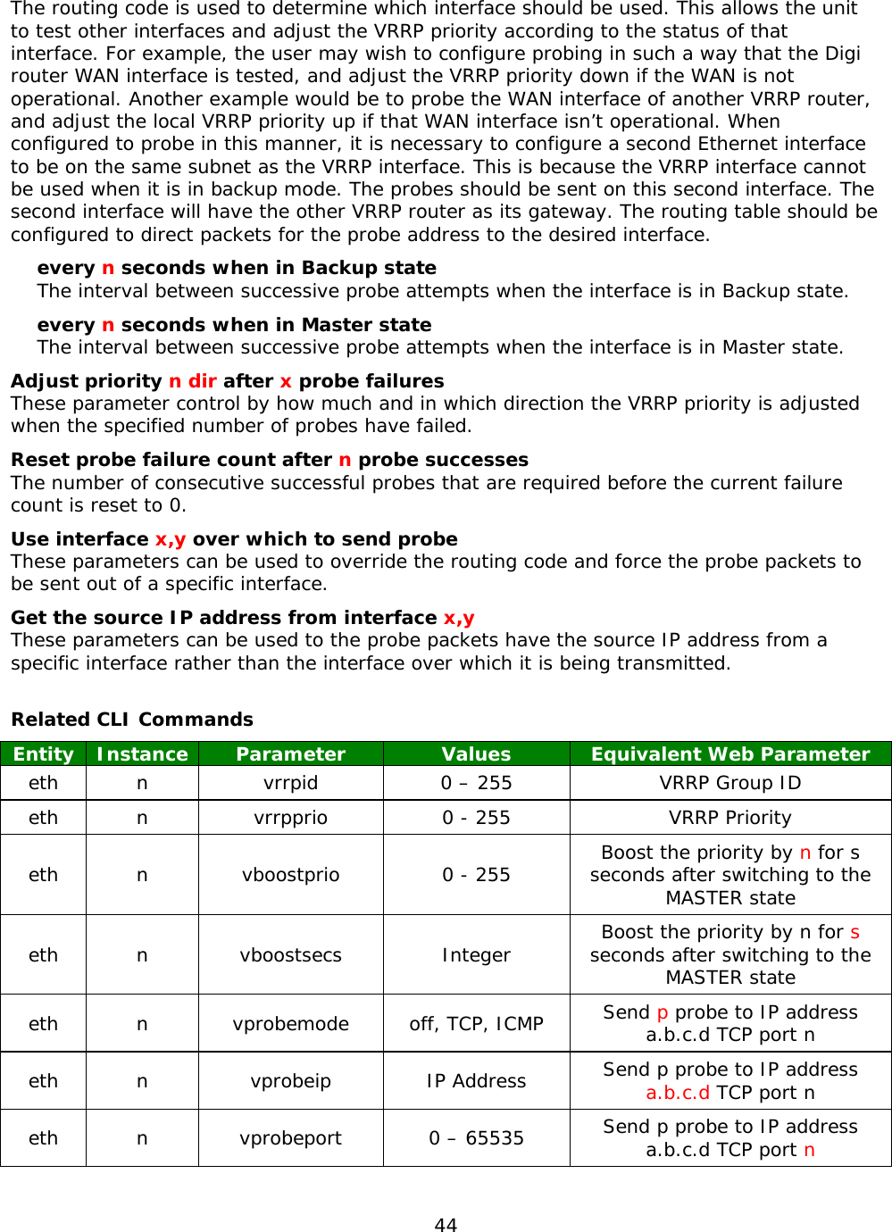
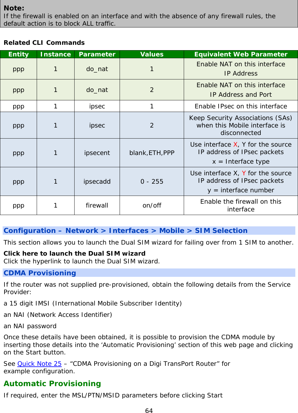
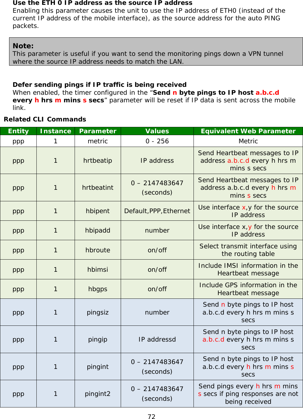
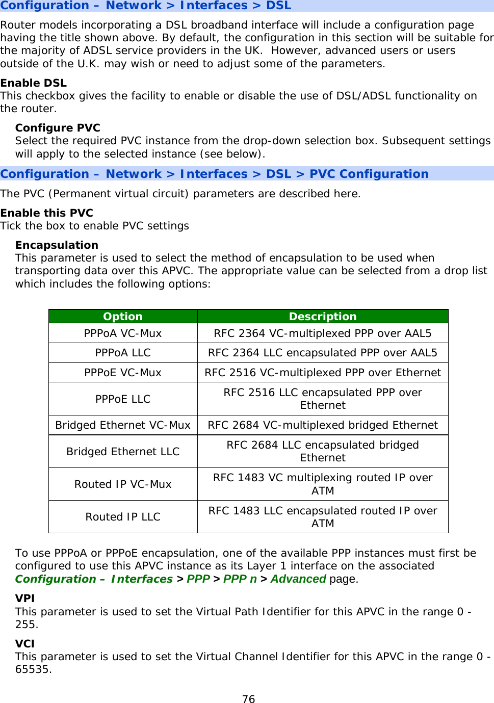
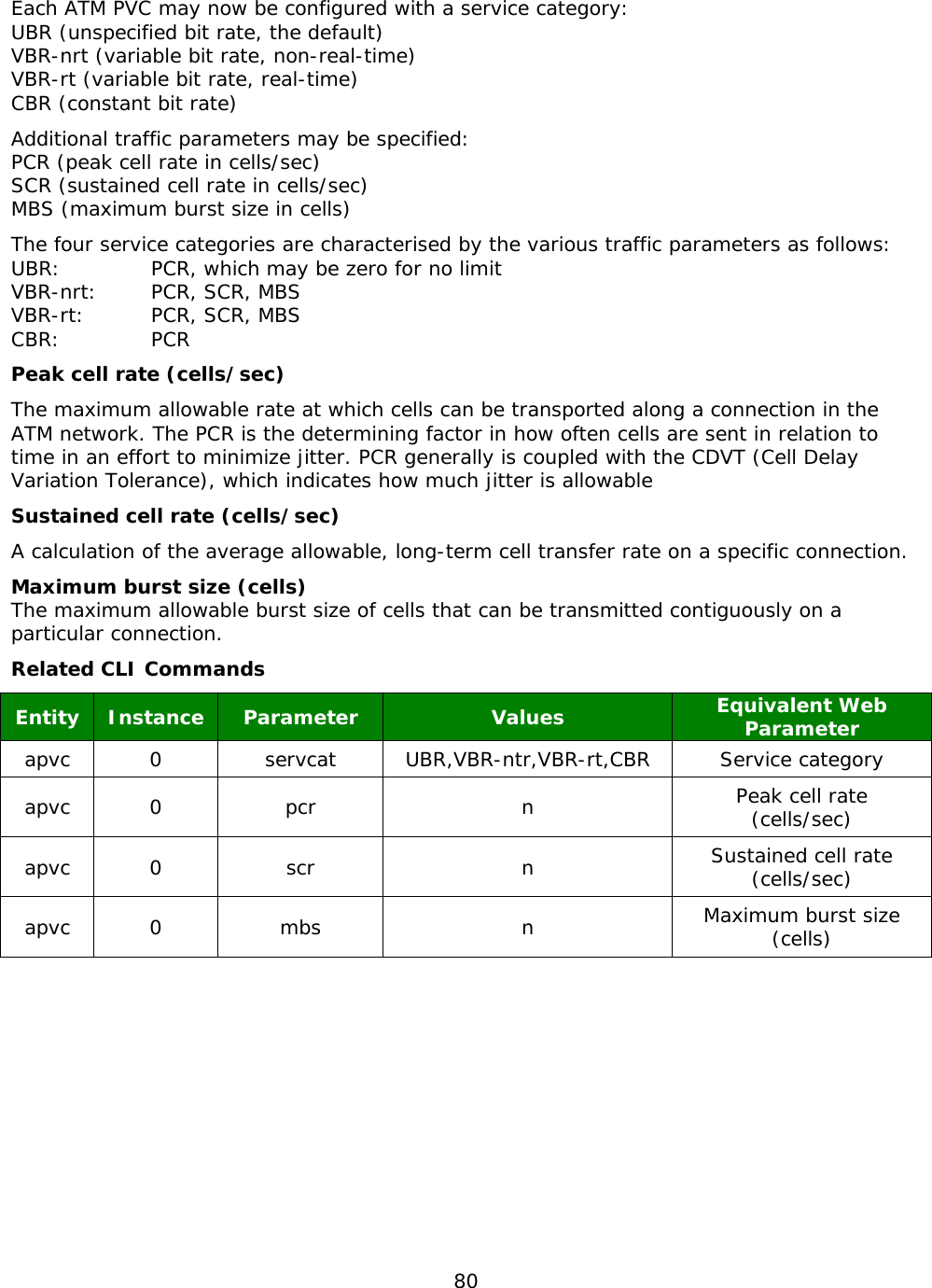
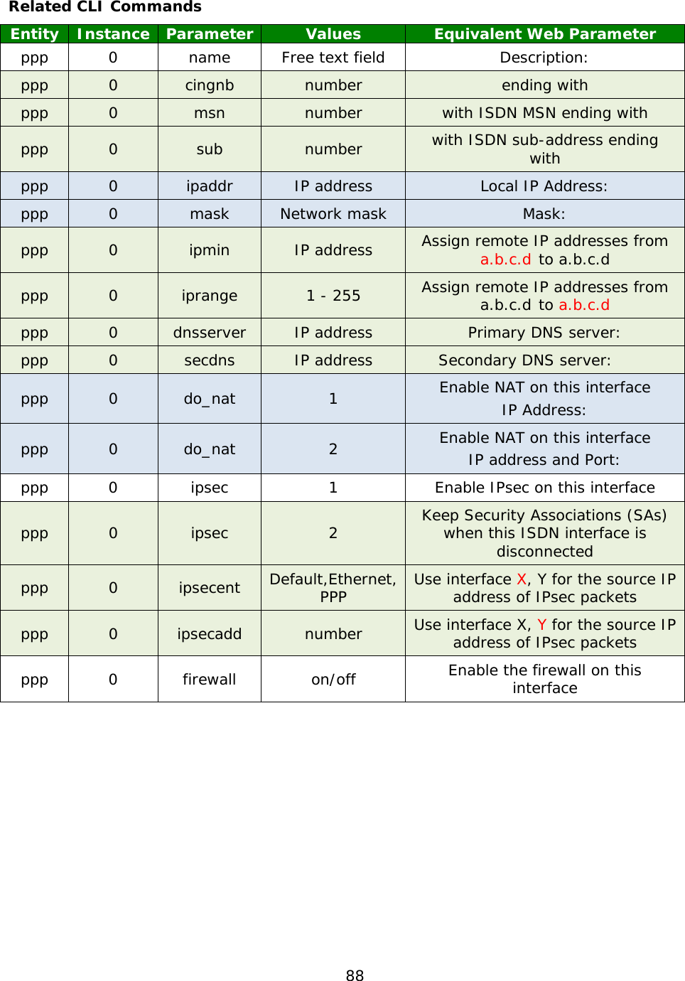
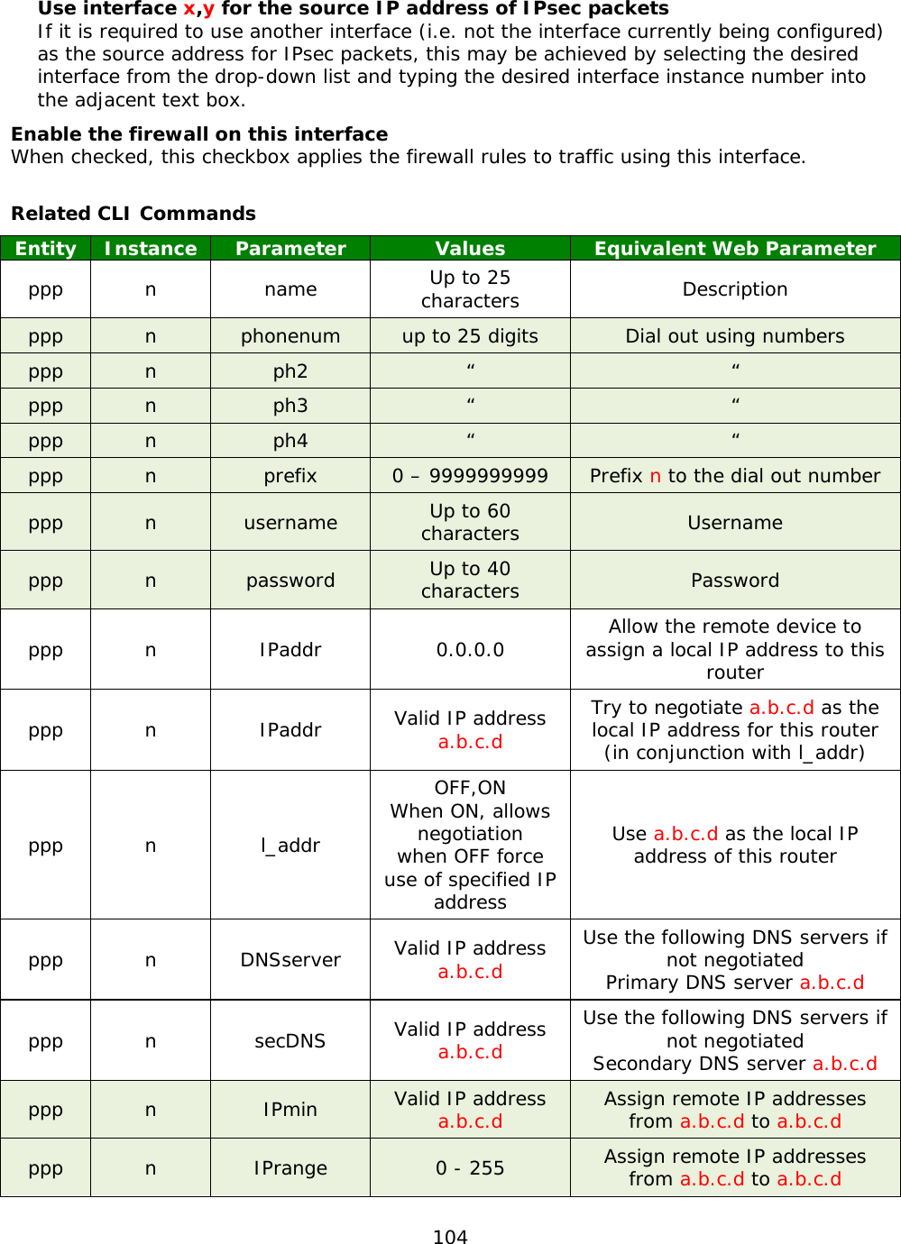
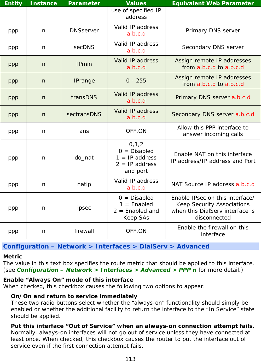
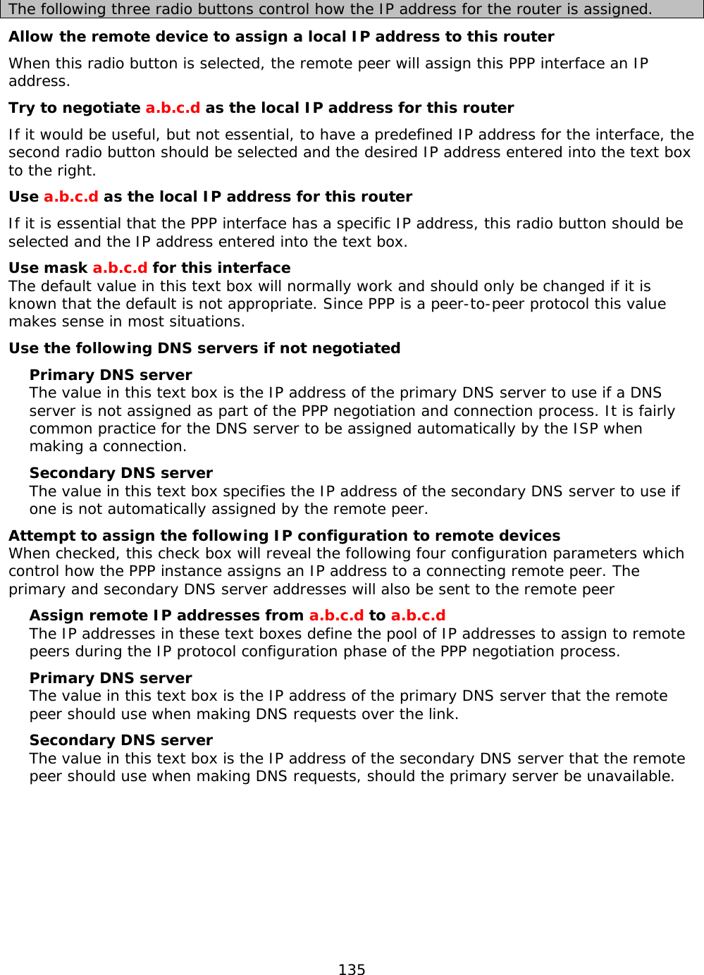
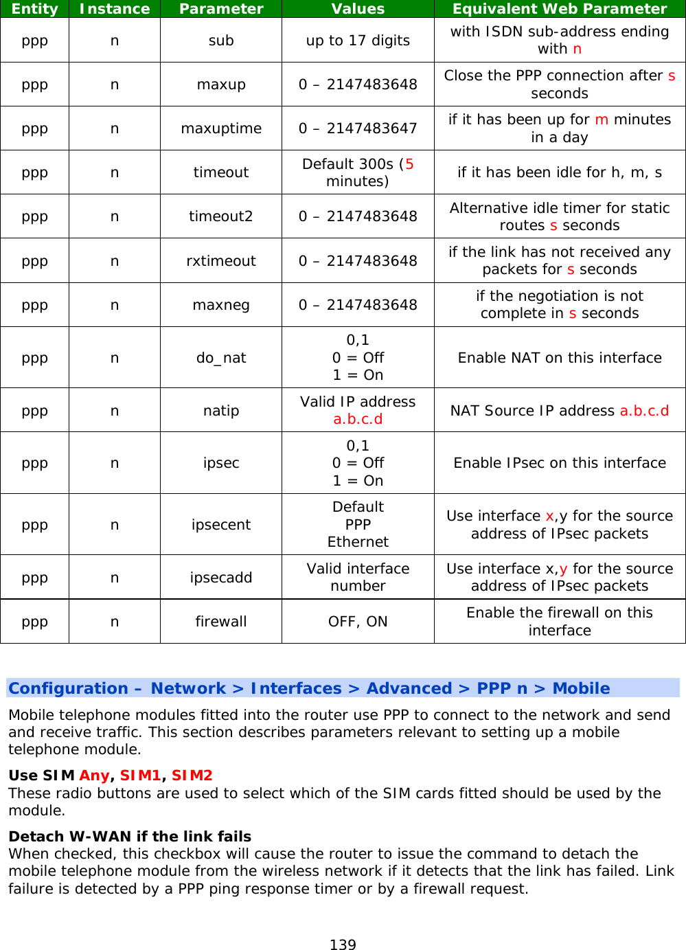
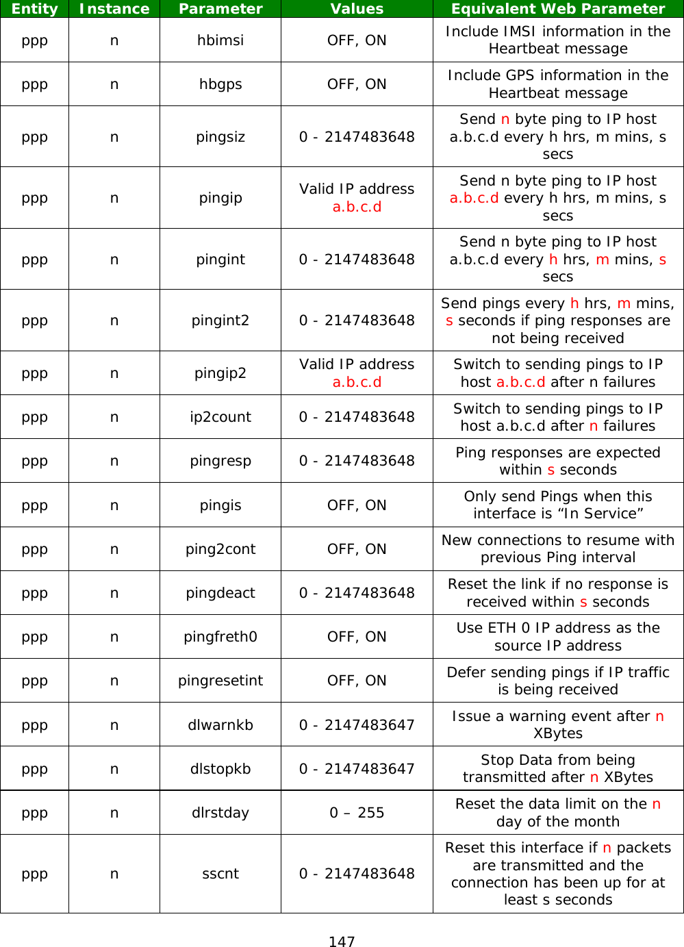
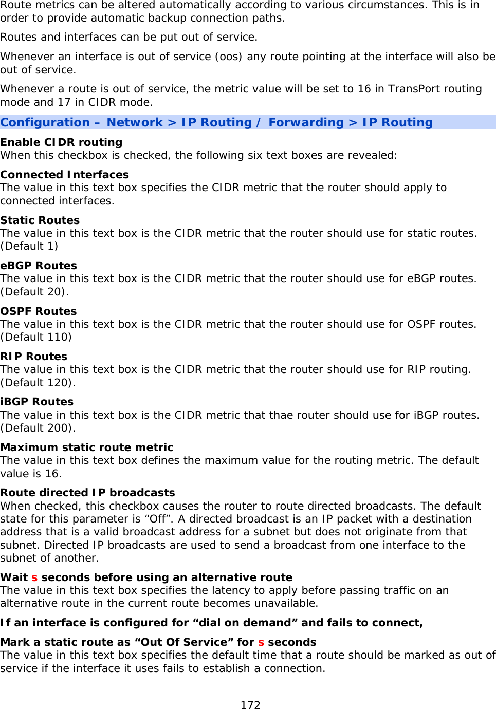
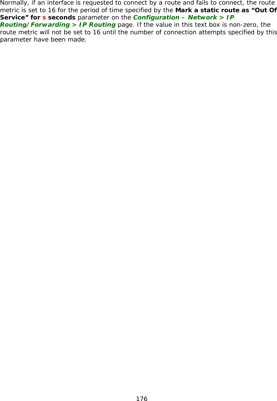
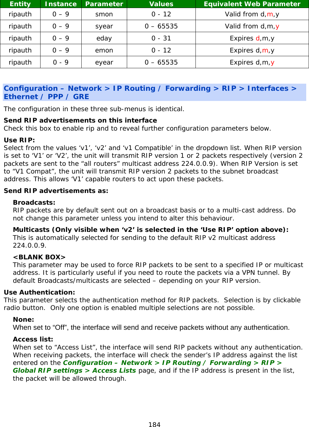
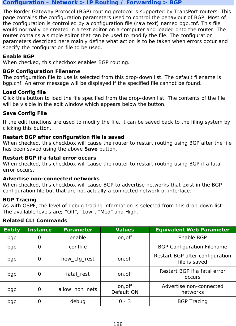
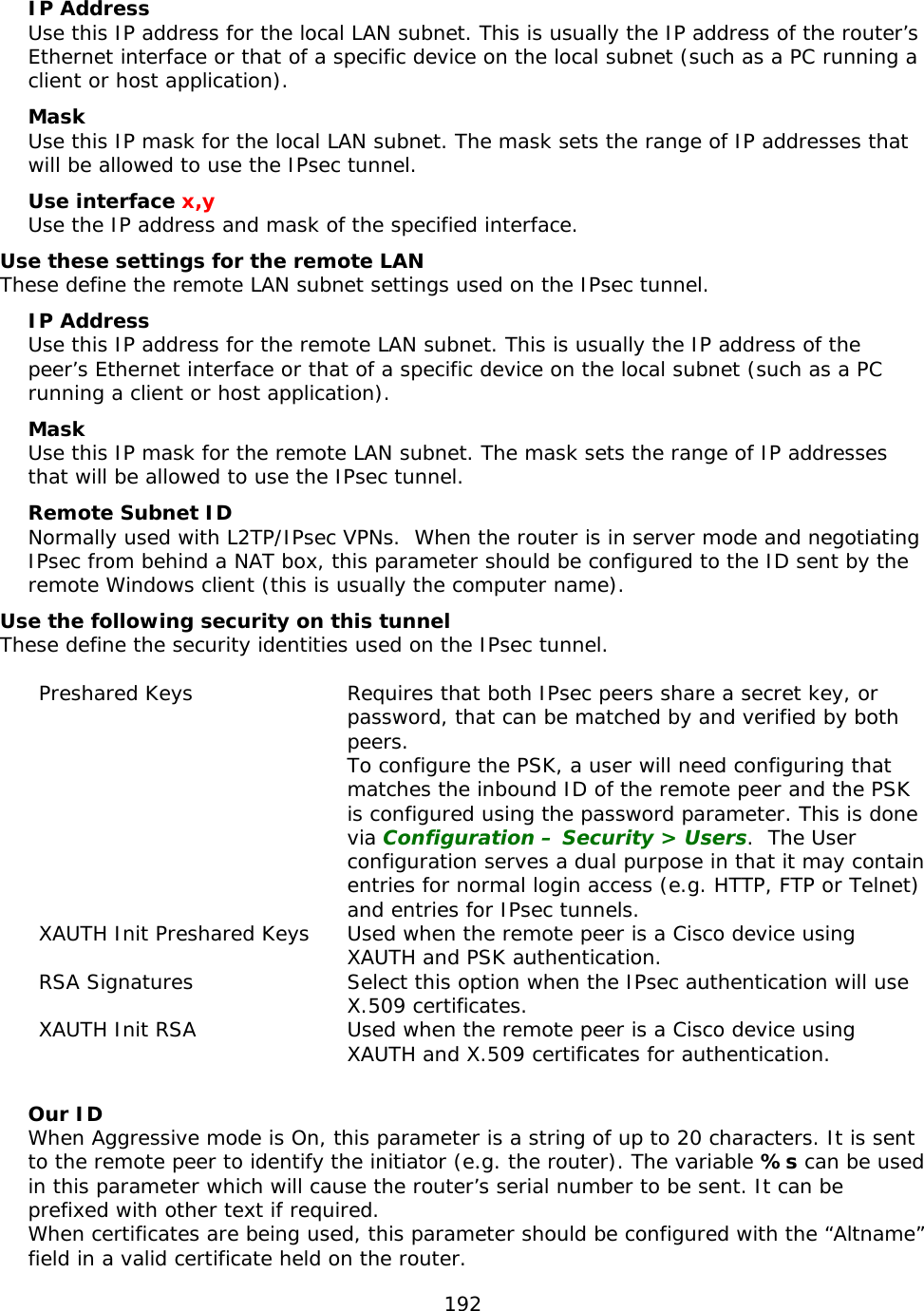
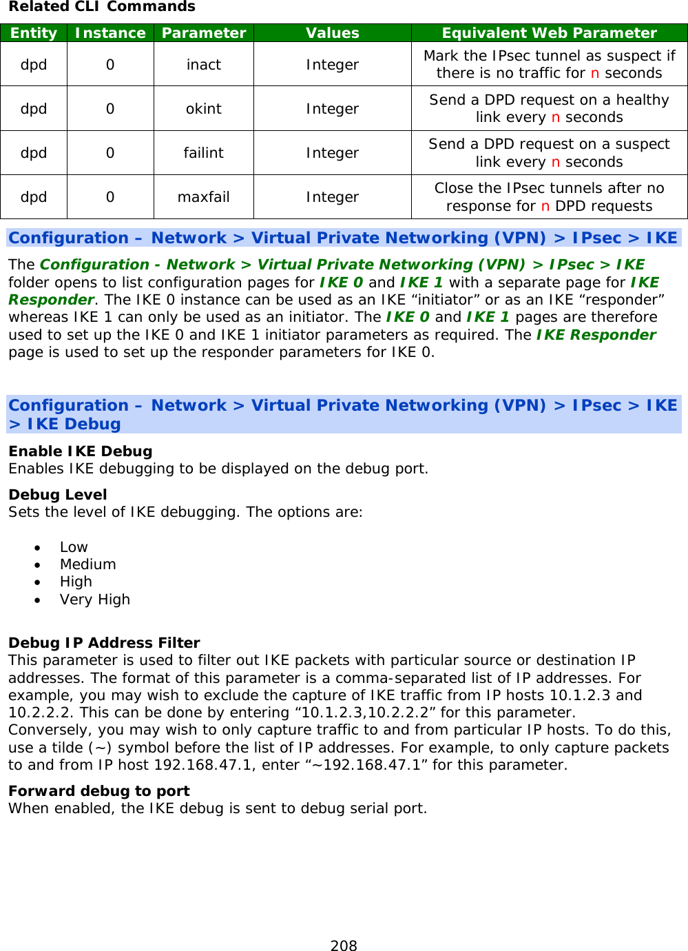
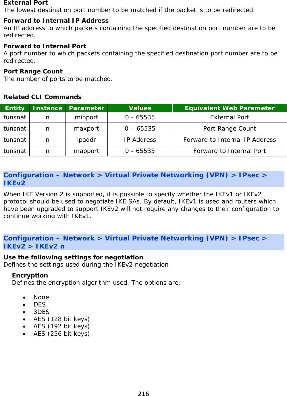
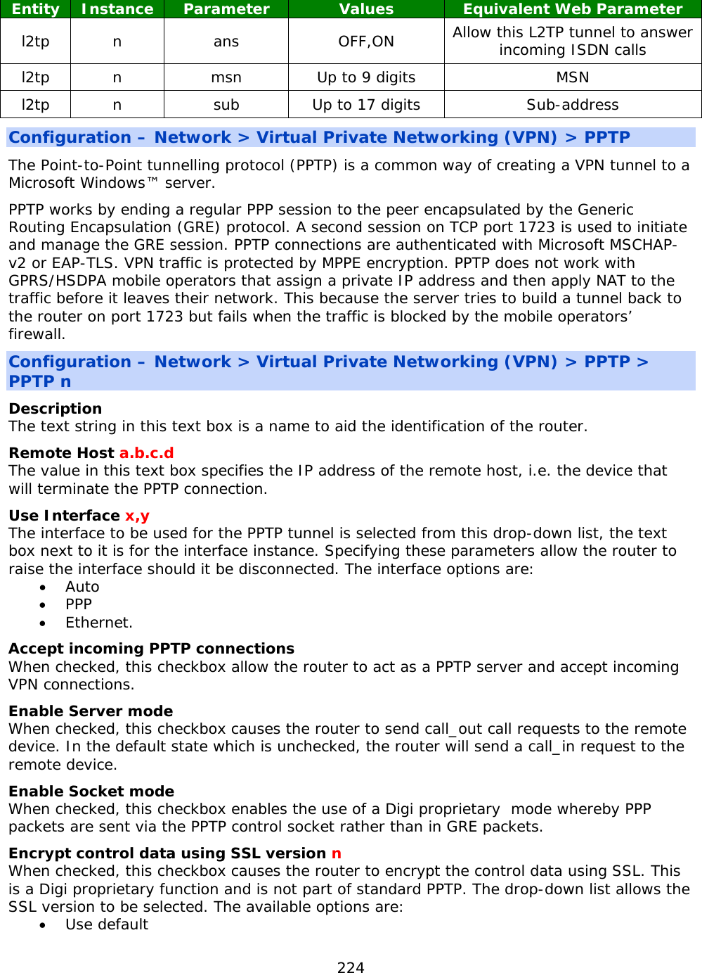
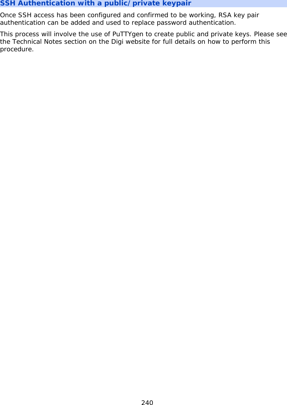
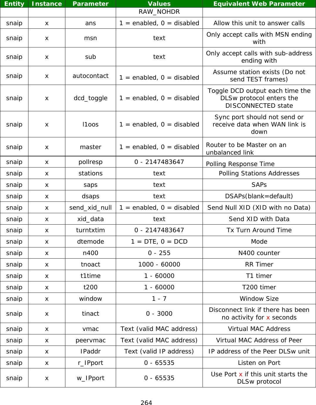
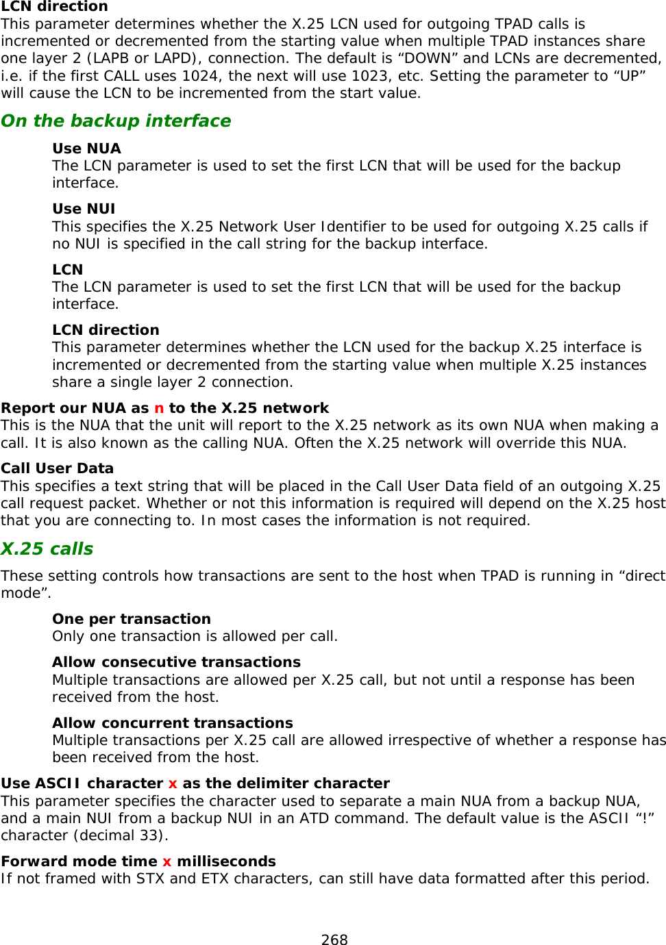
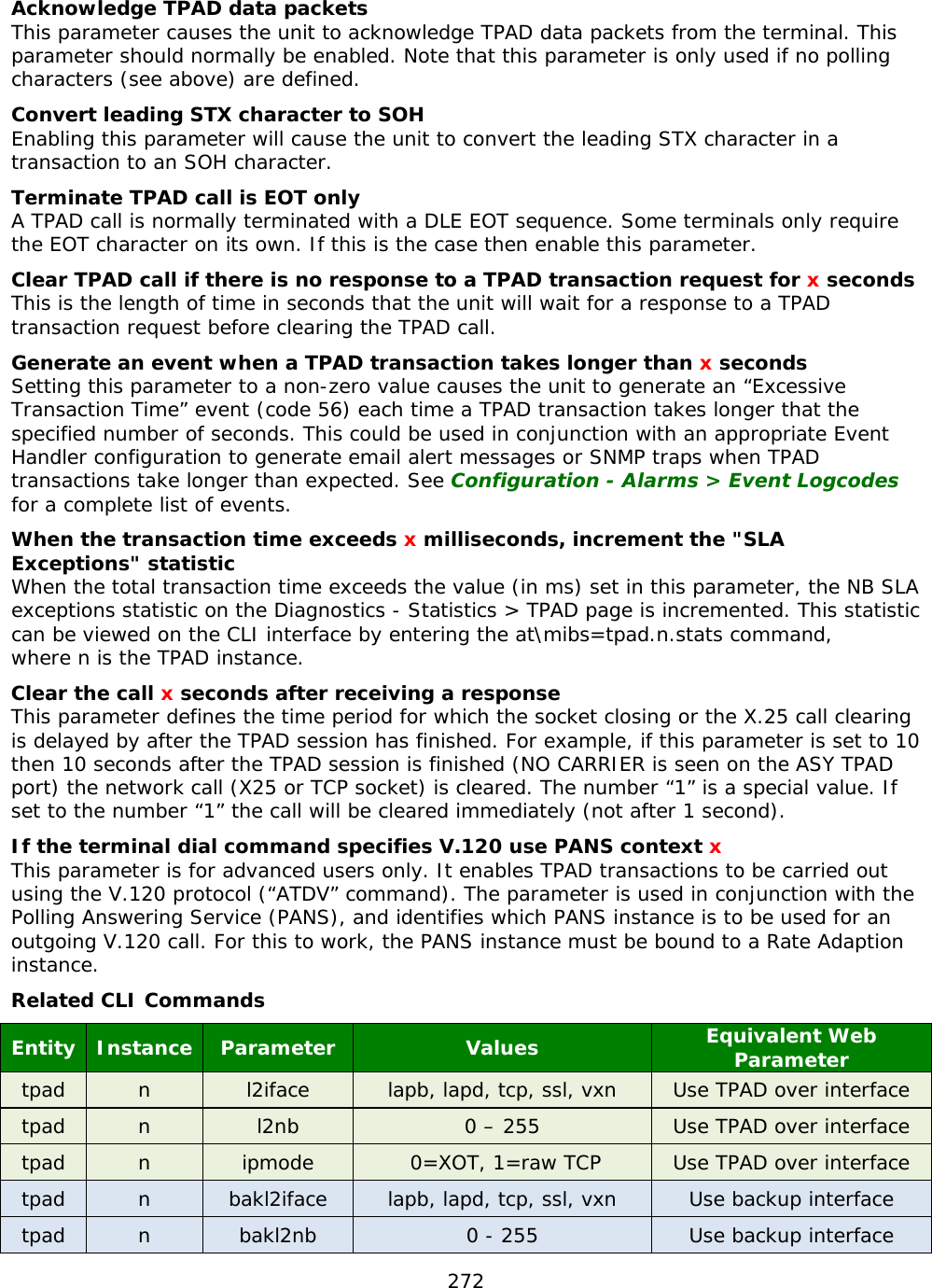
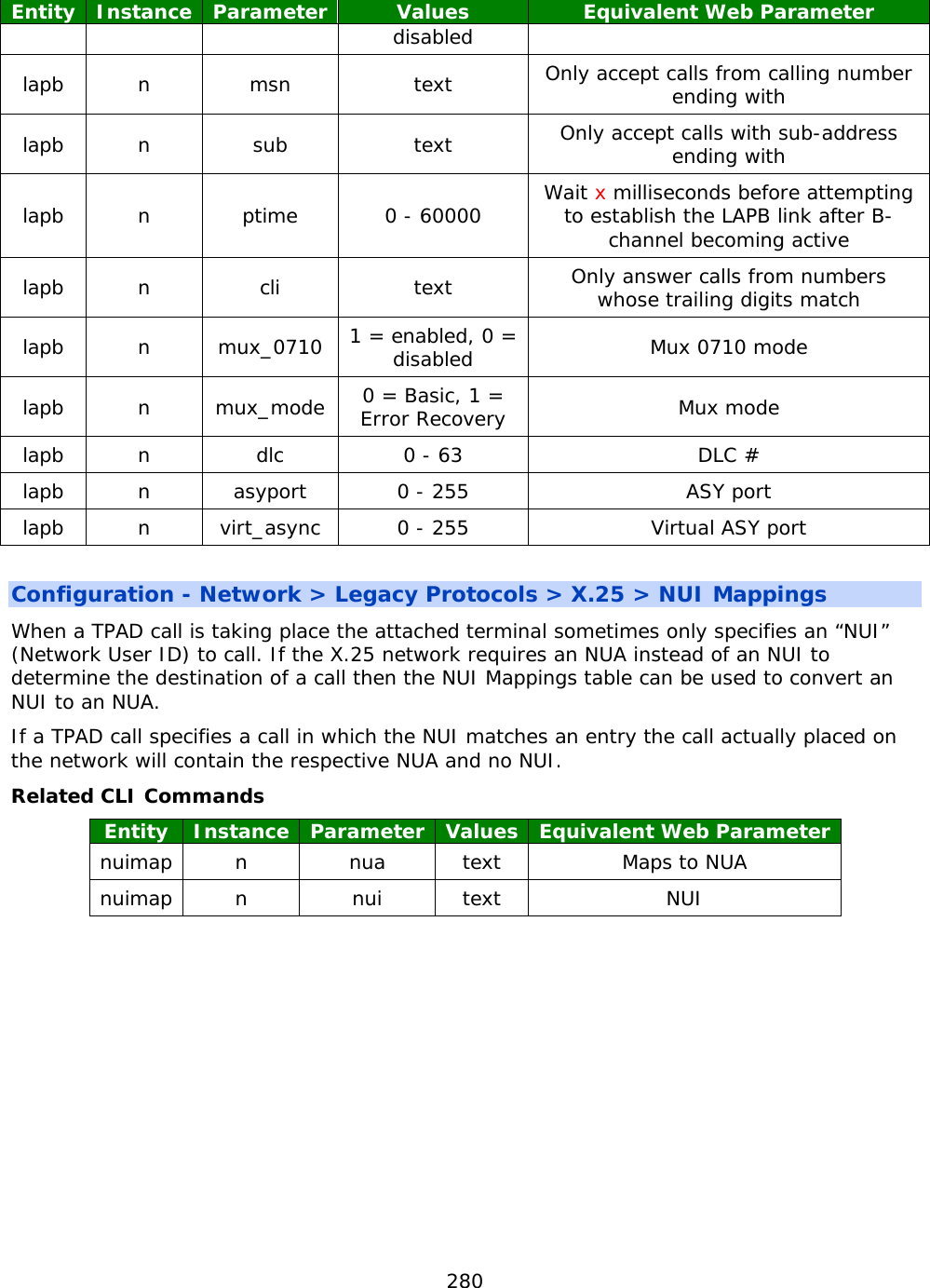
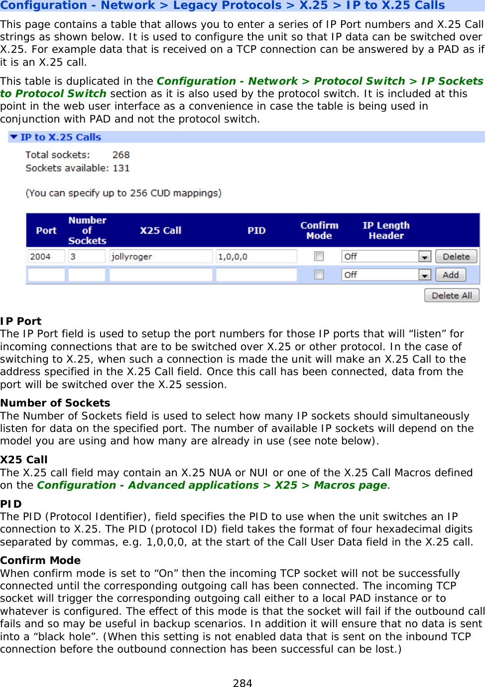
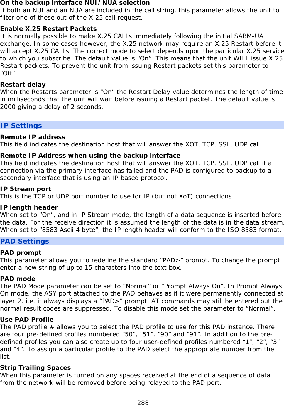
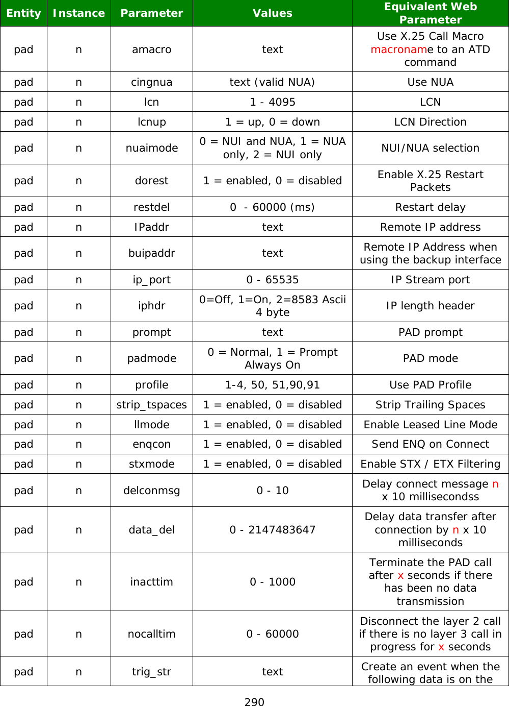
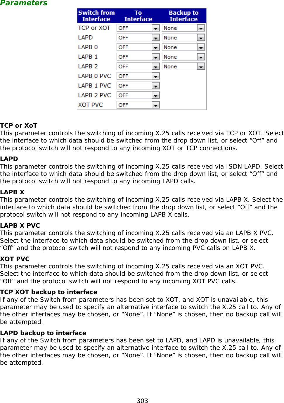
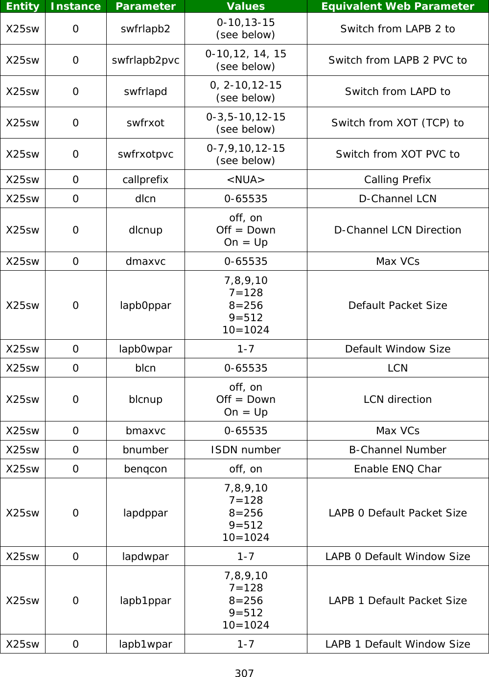
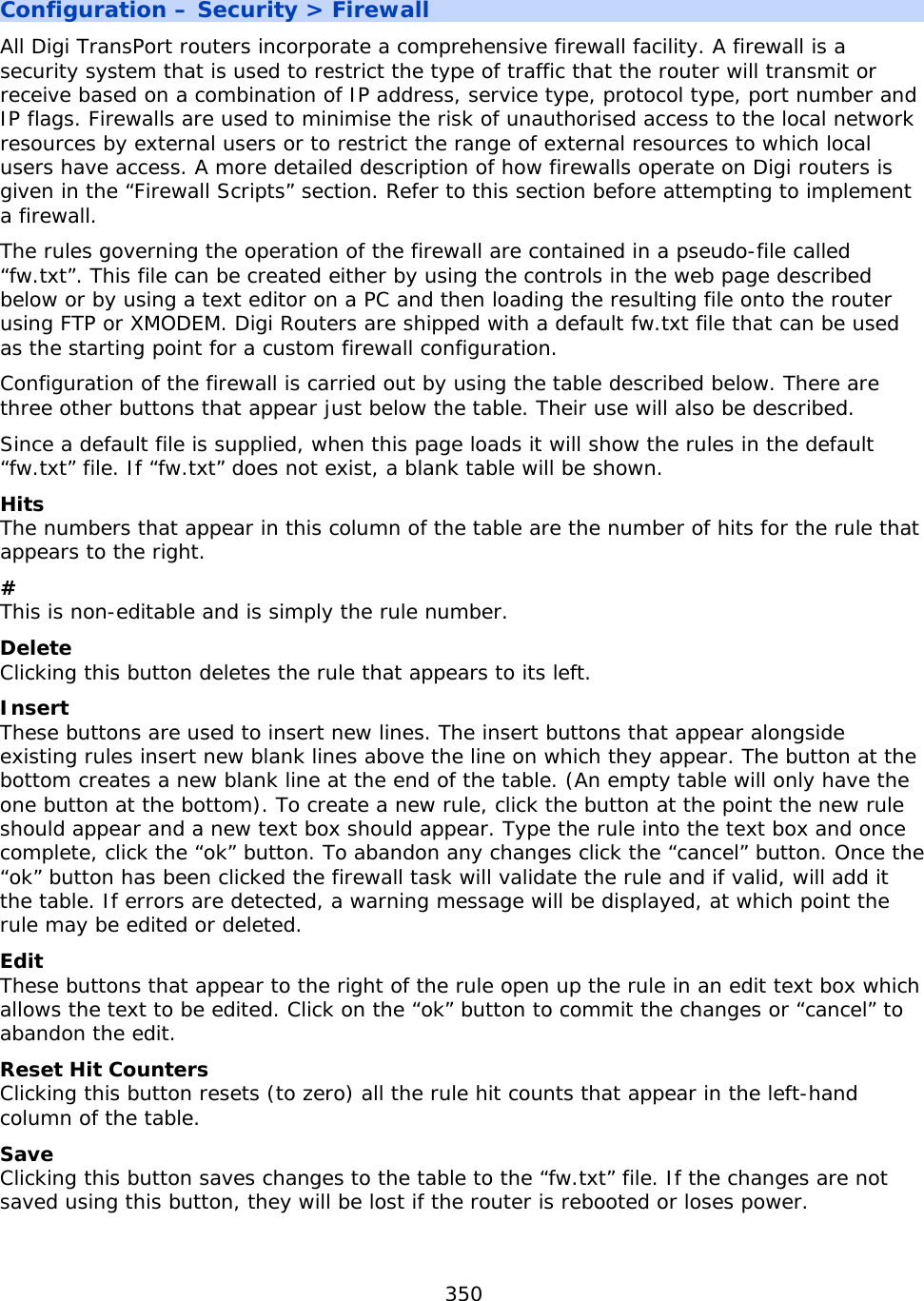
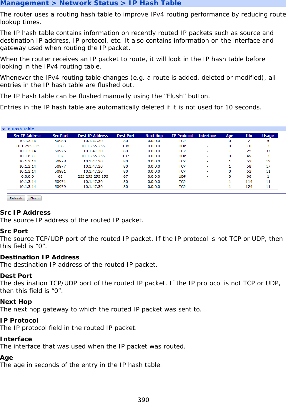
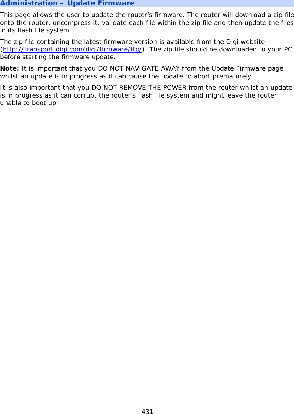
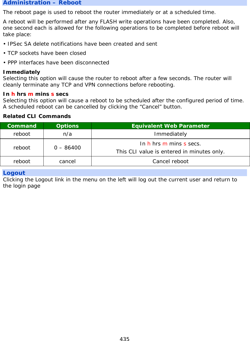
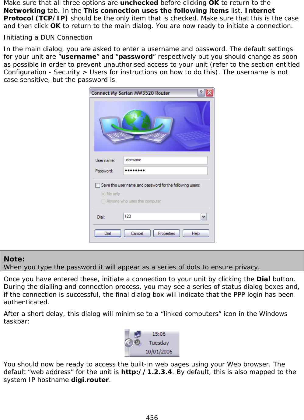
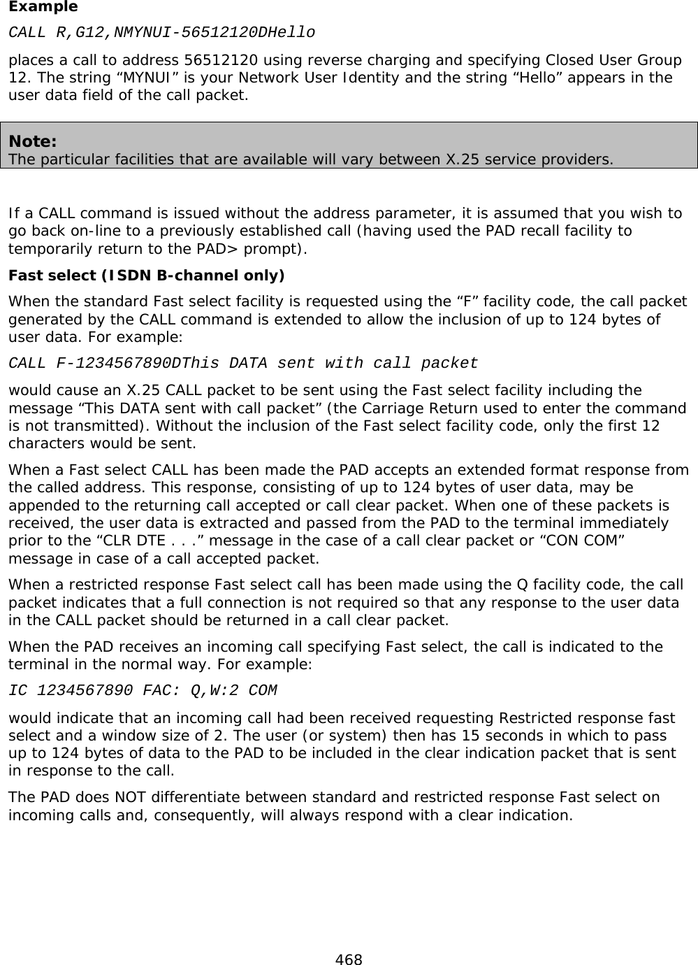
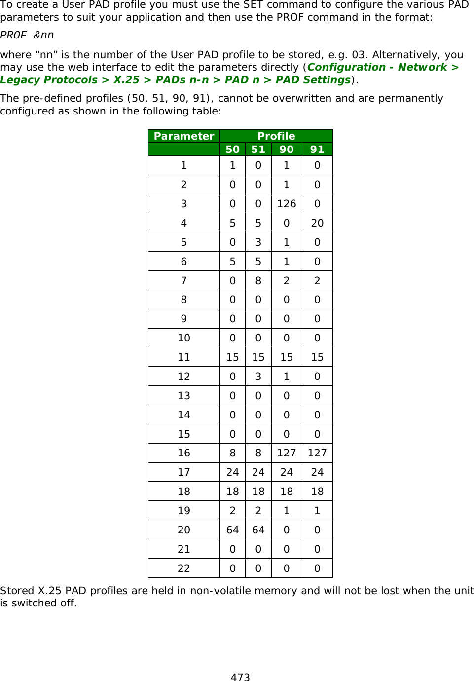
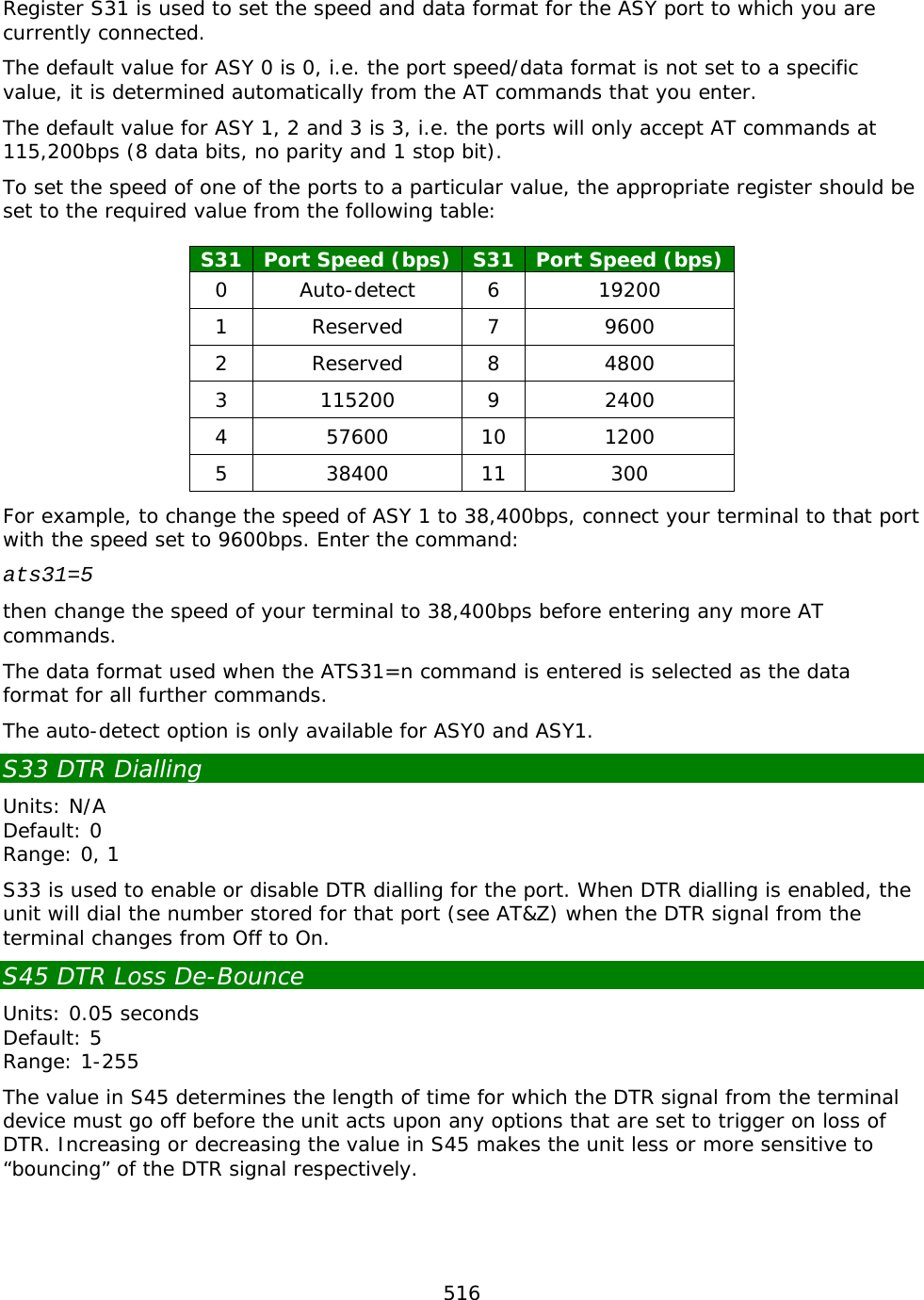
![294 8 Discard Output This parameter determines whether data received during a call is passed to the DTE or discarded. It can only be directly set by the remote system and may be used in a variety of circumstances when the remote DTE is not able to handle a continuous flow of data at high speed. Option Description 0 Normal data delivery to DTE 1 Output to DTE discarded 9 Padding after CR Slower terminal devices, such as printers, may require a delay after each Carriage Return before they can continue to process data. This parameter controls the number of pad characters (NUL - ASCII 0) that are sent after each CR to create such a delay. Option Description 0 No padding characters after CR 1 - 255 Number of padding characters (NUL) sent after CR 10 Line Folding Controls the automatic generation of a [CR],[LF] sequence after a certain line width has been reached. Option Description 0 No line folding 1 - 255 Width of line before the PAD generates [CR],[LF] 11 Port Speed This is a “read only” parameter, set automatically by the PAD and accessed by the remote system. Option Description 15 19,200 bps 14 9,600 bps 12 2,400 bps 3 2,400 bps 12 Flow Control of PAD (by DTE) Determines the flow control setting of the PAD by the DTE in the on-line data state. Option Description 0 No flow control 1 XON/XOFF flow control 3 RTS/CTS flow control (not a standard X.3 parameter)](https://usermanual.wiki/Digi/55M1644B.Manual-pt-1/User-Guide-1821845-Page-294.png)
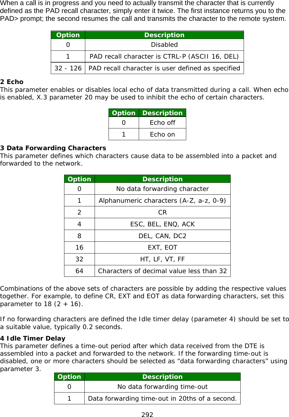
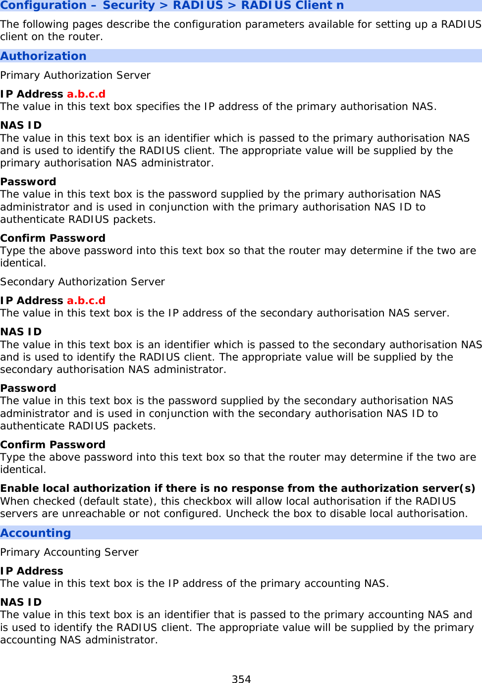
![295 13 LF Insertion (after CR) Controls the automatic generation of a Line Feed by the PAD. Option Description 0 No line feed insertion 1 Line Feeds inserted in data passed TO the DTE 2 Line Feeds inserted in data received FROM the DTE 4 Line Feeds inserted after CRs echoed to DTE The line feed values can be added together to select Line Feed insertion to any desired combination. 14 LF Padding Some terminal devices such as printers require a delay after each Line Feed before they can continue to process data. This parameter controls the number of padding characters (NUL - ASCII 0) that are sent after each [LF] to create such a delay. Option Description 0 No line feed padding. 1 - 255 Number of NUL characters inserted after LF 15 Editing Enables (1) or disables (0) local editing of data input fields by the PAD before data is sent. The three basic editing functions provided are character delete, line delete and line re-display. The editing characters are defined by parameters 16, 17 and 18. In addition, parameter 19 determines which messages are issued to the DTE during editing. When editing is enabled, the idle timer delay (parameter 4) is disabled and parameter 3 must be used to select the desired data forwarding condition. 16 Character Delete Character This parameter defines the edit mode delete character (ASCII 0-127). The default is backspace (ASCII 08). 17 Line Delete Character This parameter defines the edit mode line buffer delete character (ASCII 0-127). The default is CTRL-X (ASCII 24). 18 Line Redisplay Character Specifies the character that re-displays the current input field when in editing mode (ASCII 0-127). The default is CTRL-R (ASCII 18). 19 Editing PAD Service Signals Specifies the type of service signal sent to the DTE when editing input fields. Option Description 0 No editing PAD service signals 1 PAD editing service signals for printers 2 PAD editing service signals for terminals](https://usermanual.wiki/Digi/55M1644B.Manual-pt-1/User-Guide-1821845-Page-295.png)
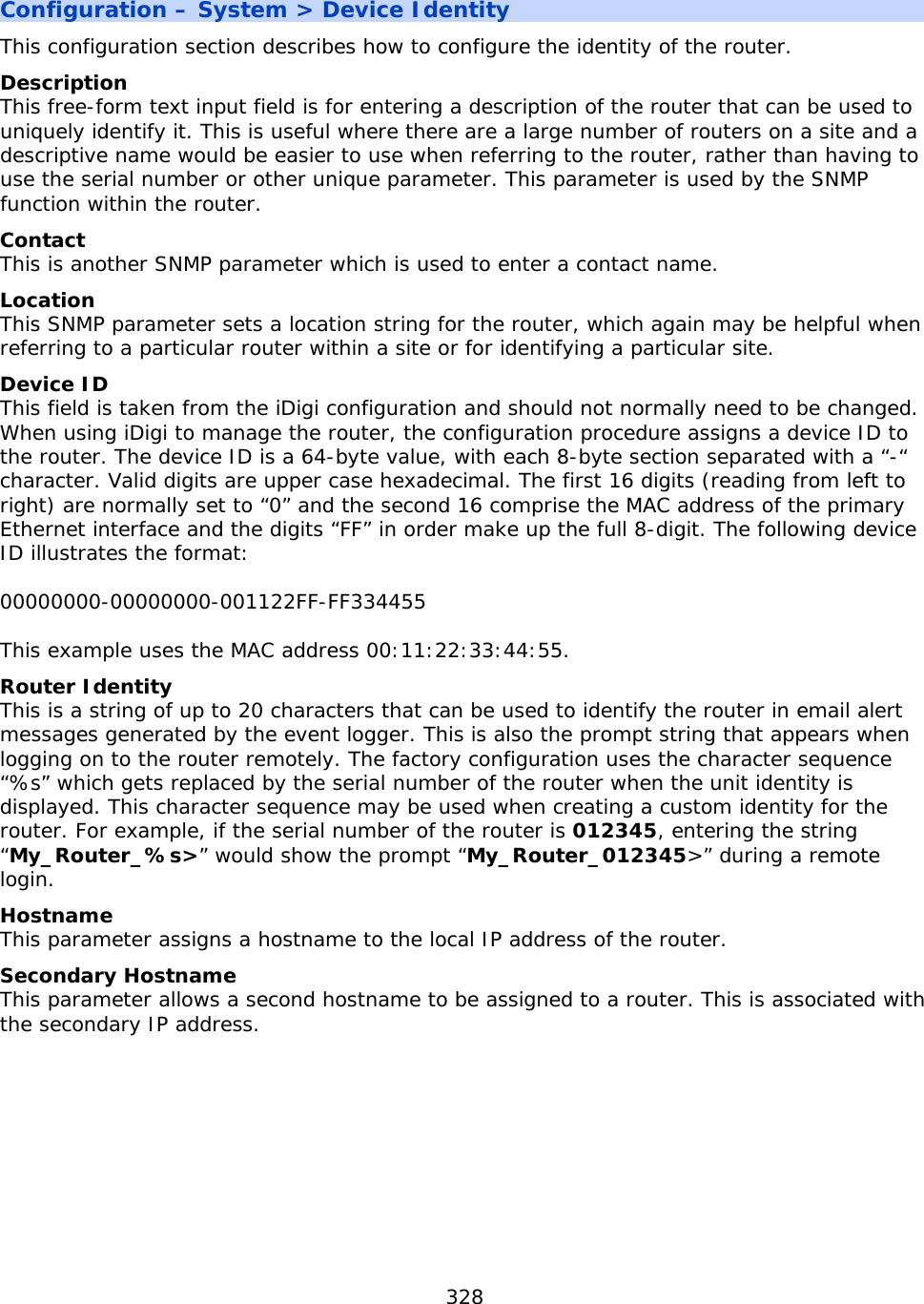
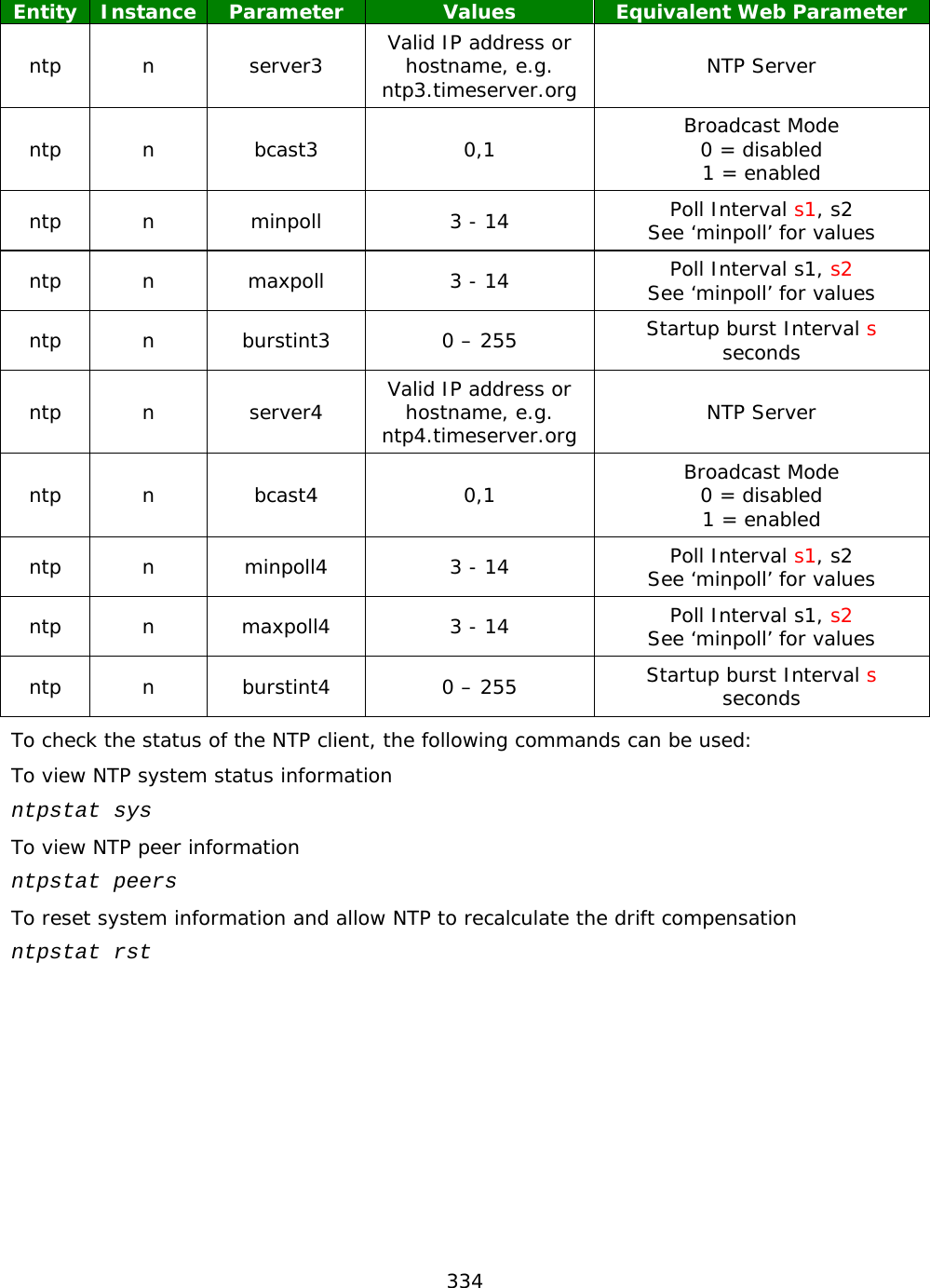
![330 Related CLI Commands Entity Instance Parameter Values Equivalent Web Parameter n/a n/a time hh [mm [ss [DD [MM [YYYY]]]]] Manually set the time Configuration – System > Date and Time > Autoset Date and Time Do not auto-set the system time This is the system default and this radio button will appear filled in when the unit is new unless a different default configuration has been supplied. Click this radio button to close the SNTP or NTP configuration pages. Auto-set the system time Selecting this radio button expands the page to include the SNTP settings. These are described below. SNTP server The hostname or IP address of the desired SNTP server is entered here. Check on Power-up This checkbox, when checked, will cause the router to attempt to connect to the SNTP server every time it boots. Update every h hours Enter the interval, in hours that the router should wait between updating the system clock. Randomly between s1 and s2 seconds It is possible to use a random update interval rather than a fixed interval. There are two text-entry boxes for this purpose, enter the minimum interval into the left-hand box and the maximum desired interval into the right-hand box. Selecting the random update will clear the fixed interval. Offset from GMT This parameter should be set to + or - the number of hours the unit’s time should be ahead or behind Greenwich Mean Time. Update for Daylight Saving Time. When checked, this checkbox causes the following parameters to appear, the router will then use those settings to automatically adjust the system time to ensure that local daylight saving is used. Start Month Use this drop-down selection box to select the month in which to switch to daylight saving time. Day Use this drop-down selection box to select the day on which to switch to daylight saving time. Hour Use this drop-down selection box to select the hour at which to switch to daylight saving time.](https://usermanual.wiki/Digi/55M1644B.Manual-pt-1/User-Guide-1821845-Page-330.png)
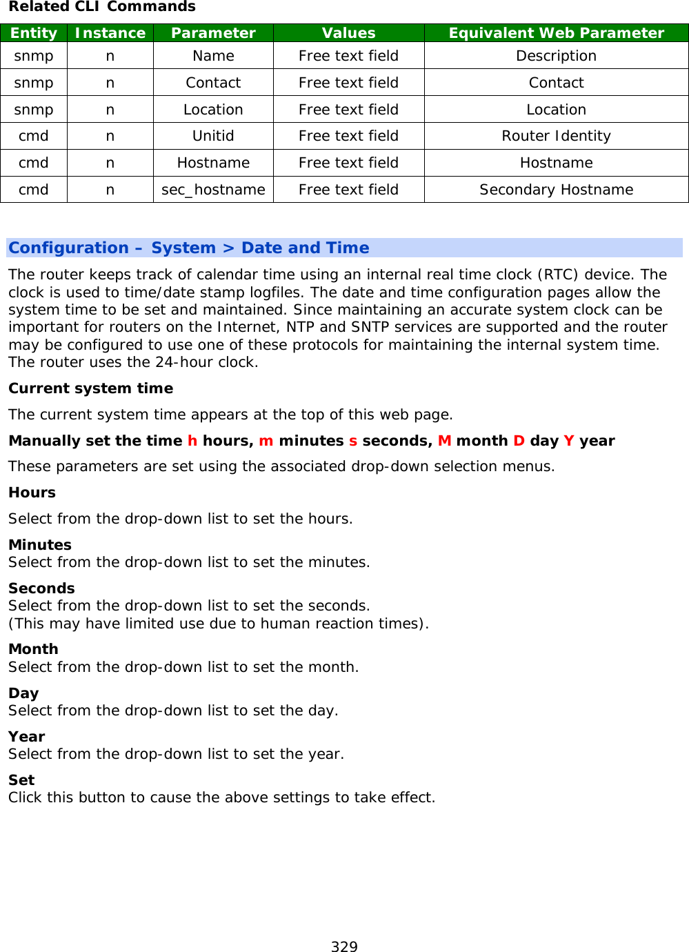
![331 End Month Use this drop-down selection box to select the desired month in which to switch back to GMT (UTC). Day Use this drop-down selection box to select the desired day on which to switch back to GMT. Hour Use this drop-down selection box to select the desired hour at which to switch back to GMT. Related CLI Commands Entity Instance Parameter Values Equivalent Web Parameter sntp n server Valid hostname or IP address sntp.timeserve.org SNTP Server sntp n pwrchk 0,1 Check on Power-up 0 = Off 1 = On sntp n interval 0 – 255 Update every h hours Default = 24 sntp n randintsecs 0 - 86400 randomly between s1 and s2 seconds Use format [s1,s2] eg min 50, max 500 would be: [50,500] sntp n offset -12 - +13 Offset from GMT sntp n dstonmon 0 – 12 Start: Month Update for Daylight Saving Time 0 disables daylight saving sntp n dstonday 0 - 31 Start: Day sntp n dstonhr 0 - 23 Start: Hour sntp n dstoffmon 0 - 12 End: Month sntp n dstoffday 0 - 31 End: Day sntp n dstoffhr 0 - 23 End: Hour sntp n ntp 0,1 0 = SNTP 1 = NTP Default = OFF Use NTP for greater accuracy Selecting this checkbox expands the page to show the NTP settings. These are described below. NTP is much more accurate than SNTP, with NTP an accuracy of 200 microseconds (1/5000 second) can be achieved. The NTP functionality is in accordance with RFC1305.](https://usermanual.wiki/Digi/55M1644B.Manual-pt-1/User-Guide-1821845-Page-331.png)

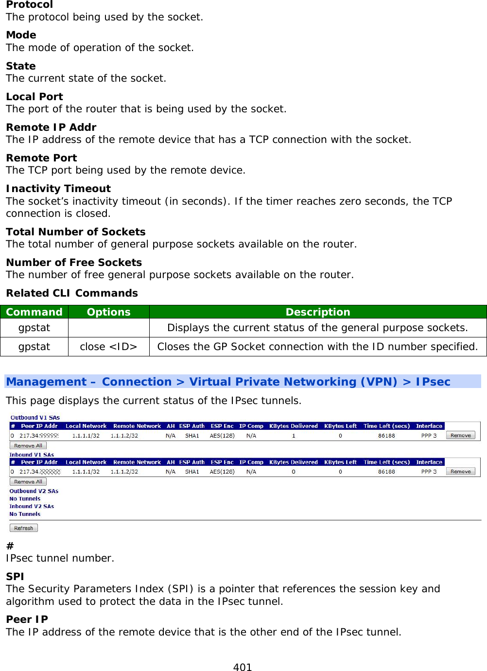
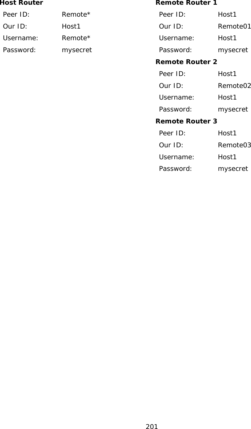
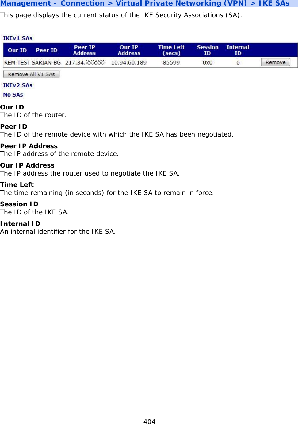
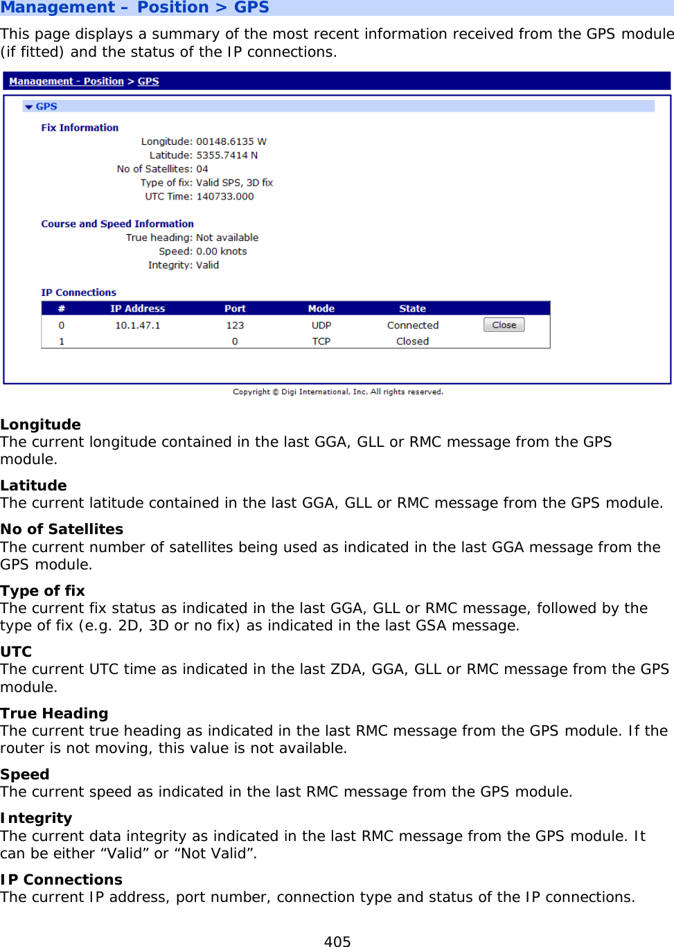
![403 Related CLI Commands Command Options Description sastat [dyn] Displays the current status of all of the IPsecs tunnels. The optional “dyn” parameter can be used to display the status of the dynamic IPsec tunnels. sastat [dyn] <first> <last> Displays the current status of the IPsec tunnels in the range from <first> to <last>. e.g. sastat 0 49 or sastat dyn 0 49 sastat [dyn] peer <peer> Displays the current status of the IPsec tunnels that match the given peer. The <peer> value can contain the ‘*’ wildcard character. e.g. sastat peer uk-north-* or sastat dyn peer uk-north-* Management – Connection > Virtual Private Networking (VPN) > IPsec peers This page displays the current status of the IPsec peers. This is the list of remote devices that have successfully negotiated an IPsec tunnel with the router. Peer IP Address The IP address of the remote device. Our ID The ID of the router. Peer ID The ID of the remote device. Dead Peer Detection (DPD) The DPD status and the time until the next DPD request. NATT Local Port The local NAT-Traversal port. NATT Remote Port The remote NAT-Traversal port.](https://usermanual.wiki/Digi/55M1644B.Manual-pt-1/User-Guide-1821845-Page-403.png)
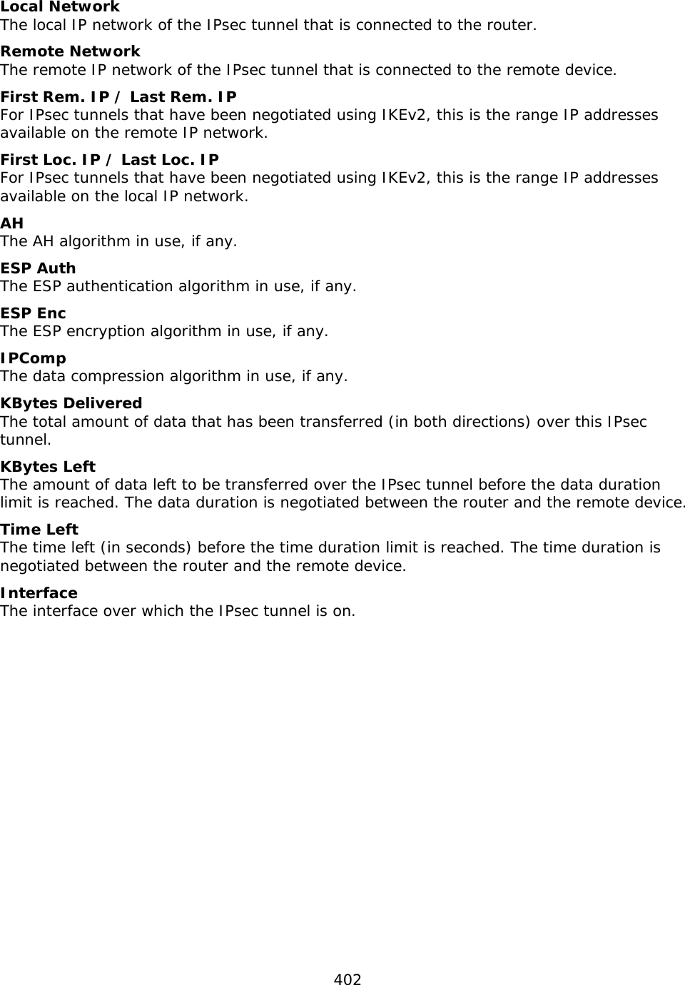
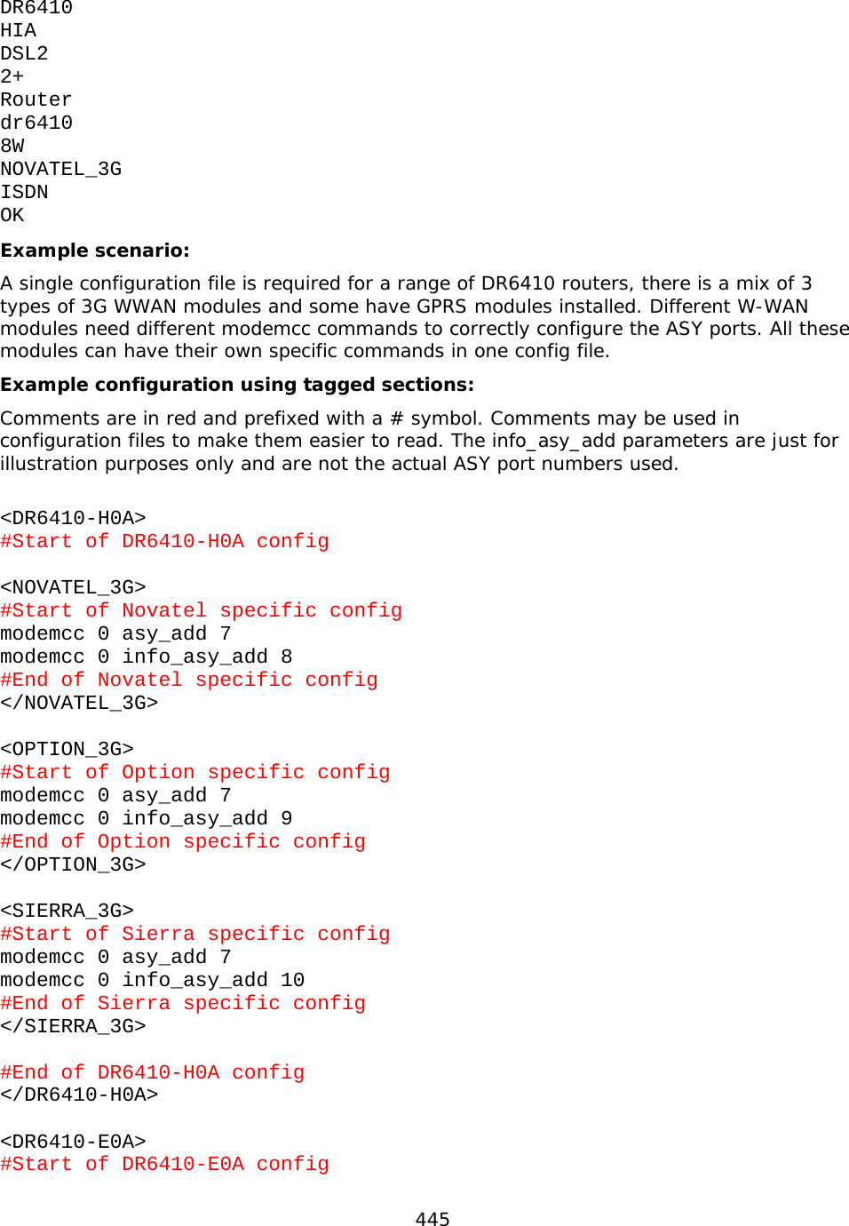
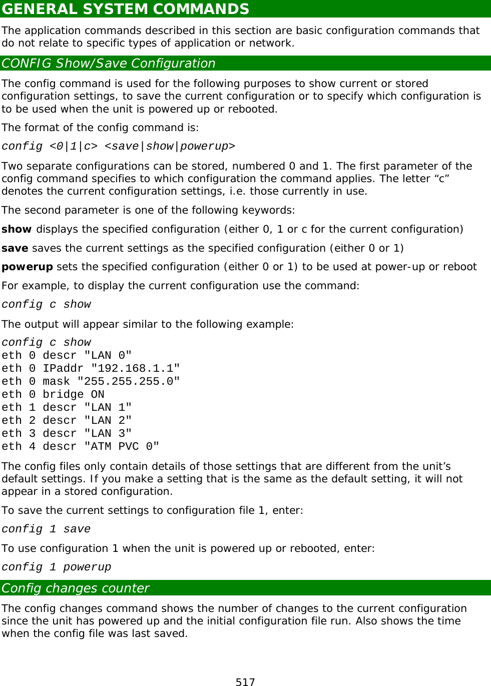
![439 MOVE Move File The move command is used to replace one file with another whilst retaining the original filename. The format is: move <fromfile> <tofile> For example, the command: move fw-temp.txt fw.txt will delete the file called “fw.txt” and then rename the file called “fw-temp.txt” as “fw.txt”. REN Rename File The ren command is used to rename files in the filing system. The format is: ren <oldfilename> <newfilename> SCAN/SCANR Scan File System The scan command performs a diagnostic check on the file system and reports any errors that are found. For example: scan Please wait... direct ....ok sbios ....ok mirror ....ok image ....ok, data ok sregs.dat ....ok x3prof ....ok CAcert.cer ....ok The scanning process may take several seconds so you should not enter any other commands until the results are listed. The scanr command works in a similar fashion, except that it will return ERROR if any file is in error. This is useful when used with scripts that can look for the ERROR failure result. TYPE Display Text File The type command is used to display the contents of a text file. The format is: type <filename> For example: type config.da0 [CFG] config last_saved "12:04:45, 31 Jan 2011" config last_saved_changes "1" config last_saved_user "ASY 0" eth 0 descr "LAN 0" eth 0 IPaddr "10.1.51.3" eth 0 mask "255.255.0.0" eth 0 bridge ON eth 1 descr "LAN 1" eth 2 descr "LAN 2" eth 3 descr "LAN 3" eth 4 descr "ATM PVC 0"](https://usermanual.wiki/Digi/55M1644B.Manual-pt-1/User-Guide-1821845-Page-439.png)

![458 SQL commands When IPSec Egroups are used with a SQL database for dynamic Eroute configuration, there are CLI commands that will help with configuration and troubleshooting on the Digi router. Local Database commands As well as using an external SQL database, the Digi can cache the SQL table entries it learns from the SQL server in RAM so if the SQL server goes offline for any reason, the database entries are still available to renew existing IPSec SA’s. To configure the caching options the command used is sql 0 <parameter> <value> The following parameters are available to configure the caching of database entries: dbsrvmem <n> This parameter is used to specify the amount of memory (RAM) the MySQL server cache should use. Where <n> is specified in multiples of 1k. e.g. 10Mb = 10240 To calculate the amount of memory to specify in this parameter: 1. Look at the size of the database file (.csv) that will be loaded into the Digi memory. 2. Double this value and add 100Kb, for example, if the csv file is 200Kb, this would make a value of 500Kb for the memory allocation. Use the command sql 0 dbsrvmem 500 3. Load the database file into memory and check the memory allocated and free using the smem command. This will show the memory allocated and left available. Increase the memory in the dbsrvmem command if required. dbfile <name> This is the name of the csv file that the Digi will use to store the table definitions (1st line) and data records. This file is stored in flash and is used to populate the database stored in RAM on power up or when a new file matching this name has just been stored. The dbfile can be populated with records or be empty except for the definitions line. The dbfile stored in RAM will be populated from both the dbfile stored in flash and (if configured) via caching items learnt from the main SQL server. The dbfile in flash can then be updated from the dbfile in RAM and saved. dbname <name> This is the name of the backup database in case the main database goes offline. This name needs to match the database name in use on the SQL server. learn <off|on> When enabled, the Digi will cache entries learnt via the main SQL database in a file stored in RAM. This can be used as a backup in the event of the main SQL database going offline. To use learning mode, at least one column in the csv dbfile must be marked as a unique key, with the U prefix. For example, remip is marked as the unique key: peerip[IP],bakpeerid[IP],peerid[K20],password[20],ourid[20],remip[UKIP],remmsk[IP]](https://usermanual.wiki/Digi/55M1644B.Manual-pt-1/User-Guide-1821845-Page-458.png)

![467 X.28 Commands Once an X.25 session layer has been established the unit switches to “PAD” mode. In this mode operation of the PAD is controlled using the standard X.28 PAD commands listed in the following table: Command Description CALL Make an X.25 call CLR Clear an X.25 call ICLR Invitation to CLR INPAR? List X.3 parameters of specified PAD instance INPROF Load or save specified PAD profile INSET Set X.3 parameters of specified PAD instance INT Send Interrupt packet LOG Logoff and disconnect PAR? List local X.3 parameters PROF Load or save PAD profile RESET Send reset packet RPAR? List remote X.3 parameters RSET Set remote X.3 parameters SET Set local X.3 parameters STAT Display channel status CALL Make an X.25 Call The full structure of a CALL command is: CALL [<facilities->]<address>[D<user data>] where: <facilities-> is an optional list of codes indicating the facilities to be requested in the call (separated by commas, terminated with a dash) <address> is the destination network address. <user data> is any optional user data to be included with the call. The facility codes supported are: F Fast select - no restriction Q Fast select - restricted response Gnn Closed User Group Gnnnn Extended Closed User Group R Reverse charging N<NUI> Network User Identity code (NUI)](https://usermanual.wiki/Digi/55M1644B.Manual-pt-1/User-Guide-1821845-Page-467.png)
![469 Network User Identity (NUI) The N facility code allows you to include your Network User Identity in the call packet. For security reasons the PAD echoes each character as an asterisk (*) during the entry of an NUI. Some X.25 services use the NUI field to pass both a username and password for validation. For example, if your Username is MACDONALD and your password is ASDF, a typical CALL command would have the format: CALL NMACDONA;ASDF-56512120 where the “;” is used to separate the username from the password. Closed User Group (CUG) Most X.25 networks support Closed User Groups. They are used to restrict subscribers to only making calls or receiving calls from other members of the same CUG. The CUG number effectively provides a form of sub-addressing that is used in conjunction with the NUA to identify the destination address for a call. When the G facility code is specified in a CALL packet, it must be followed by the CUG number. This may be a 2 or 4 digit number. If you are a member of a closed user group, the network may restrict you to only making calls to or receiving calls from other members of the same group. Reverse charging Reverse charging, specified using the R facility code, allows outgoing calls to be charged to the account of destination address. Whether or not a call is accepted on a reverse charging basis is determined by the service provider and by the type of account held by the called user. Calling user data The calling user data field for a normal call may contain up to 12 bytes of user data. If the first character is an exclamation mark (!), the PAD omits the four byte protocol identifier and allows the full 16 bytes as user data. The same is true for a fast select call except that the maximum amount of user data is increased from 124 to 128 bytes. When entering user data, the tilde character (~) may be used to toggle between ASCII and binary mode. In ASCII mode data is accepted as typed but in binary mode each byte must be entered as the required decimal ASCII code separated by commas. For example to enter the data “Line1” followed by [CR][LF] and “Line2” you would enter: DLine1~13,10~Line2 Aborting a CALL An X.25 CALL may be aborted using the X.28 CLR command, by pressing [Enter] or by dropping DTR from the terminal while the call is in progress. Dropping DTR will also terminate an established call. If a call is terminated by the network or by the remote host, the unit returns a diagnostic message before the NO CARRIER result code. Messages may be numeric or verbose depending on the setting of the ATV command. The following table lists the verbose messages and equivalent numeric codes: Code Verbose message 1 Unallocated (unassigned) number 2 No route to specified transit network](https://usermanual.wiki/Digi/55M1644B.Manual-pt-1/User-Guide-1821845-Page-469.png)
![474 When used in the format: prof nn the PROF command loads the stored profile specified by “nn”. RESET Send Reset Packet RESET is used to issue a reset for the current call to the network. It does NOT clear the call but it does return the network level interface to a known state by re-initialising all Level 3 network control variables. All data in transit will be lost. RPAR? Read Remote X.3 Parameters RPAR? lists the current X.3 parameter settings for the remote system. RSET Set Remote X.3 Parameters RSET is used to set one or more X.3 parameters for the remote system. It is entered in the format: RSET par #:value[,par #:value[,par #:value ...]] SET Set Local X.3 Parameters SET is used to set one or more of the local X.3 parameters for the duration of the current session. The format of the command is: SET par #:value[,par #:value[,par #:value ...]] STAT Display Channel Status STAT displays the current status for each logical channel indicating whether it is free or engaged. For example: stat PAD STATE 1 ENGAGED 2 FREE 3 FREE 4 FREE](https://usermanual.wiki/Digi/55M1644B.Manual-pt-1/User-Guide-1821845-Page-474.png)
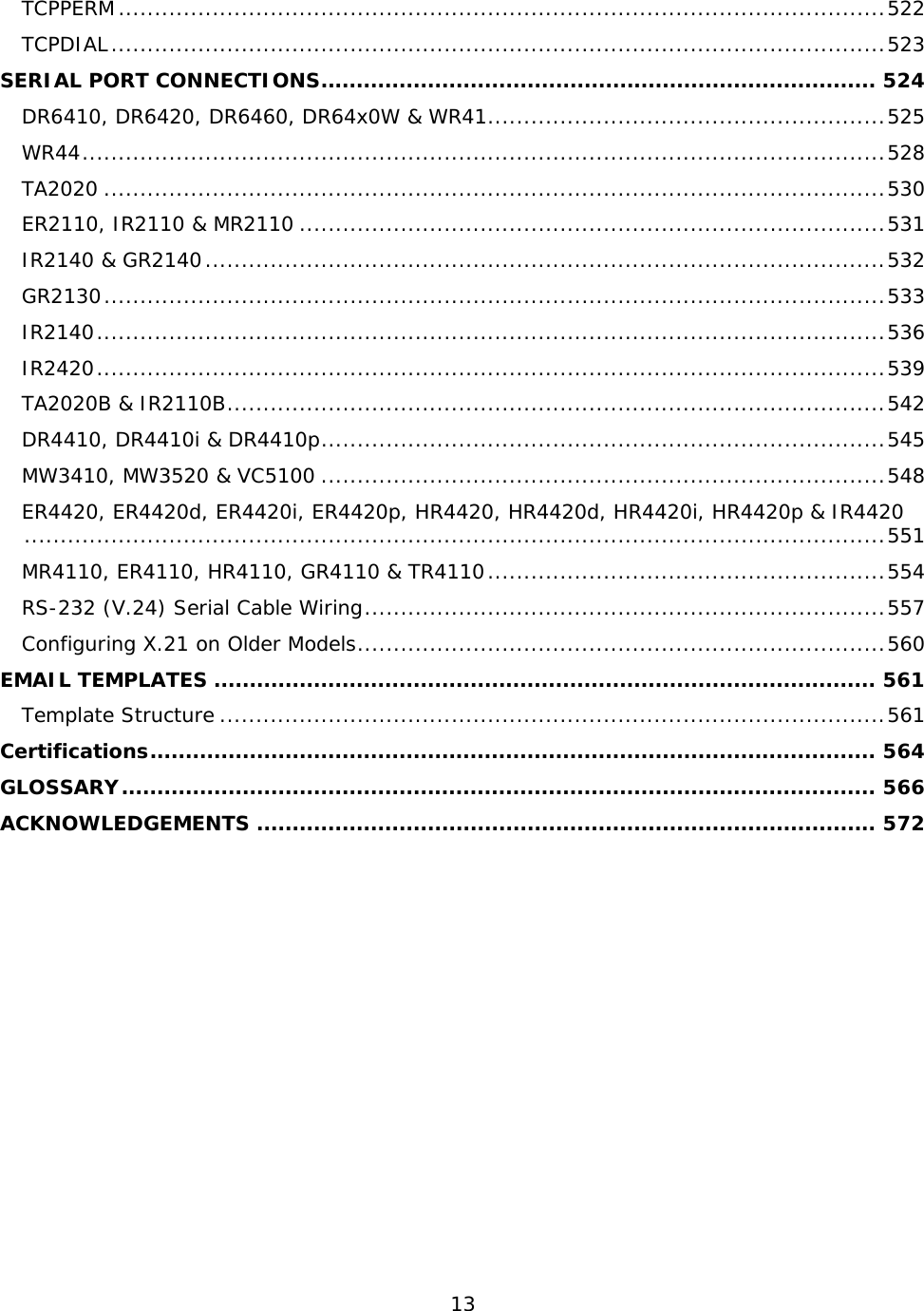
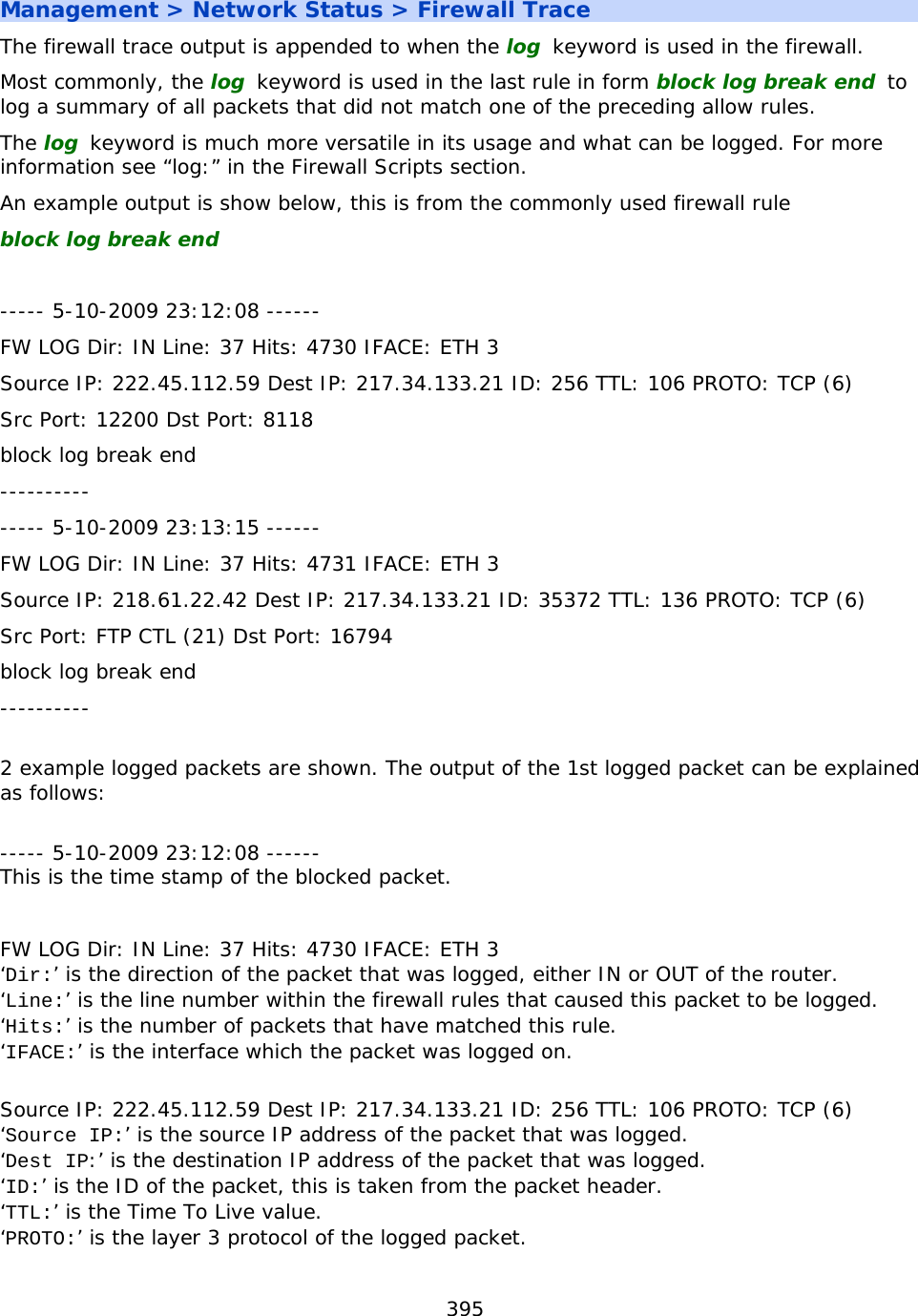
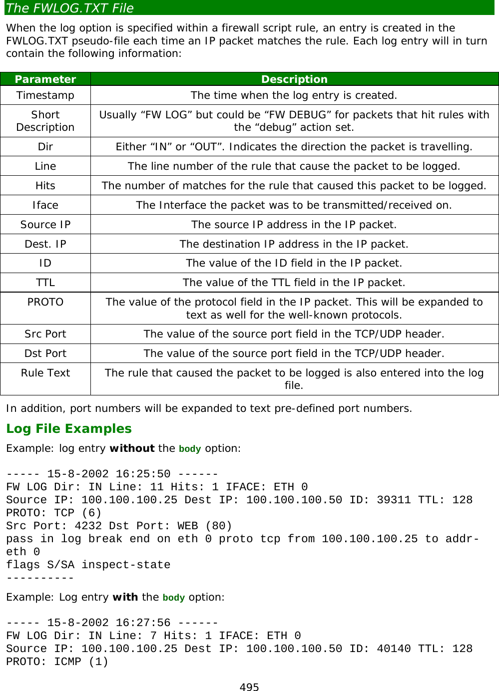
![481 Filter Rules The syntax for a filter rule is: [action] [in-out] [options] [tos] [proto] [dnslist] [ip-range] [inspect-state] When the firewall is active, the script is processed one line at a time as each packet is received or transmitted. Even when a packet matches a filter-rule, processing still continues and all the other filter rules are checked until the end of the script is reached. The action taken with respect to a particular packet is that specified by the last matching rule. With the break option however the script processing can be redirected to a new location or to the end of the script if required. The default action that the firewall assigns to a packet is to block. This means that if the packet does not match any of the rules it will be blocked. The various fields of a script rule are described below: [action] The [action] field may be specified as block, pass, pass-ifup, dscp, vdscp or debug. These operate as follows: block The block action prevents a packet from being allowed through the firewall. When block is specified an optional field can be included that will cause an ICMP packet to be returned to the interface from which that packet was received. This technique is sometimes used to confuse hackers by having different responses to different packets or for fooling an attacker into thinking a service is not present on a network. The syntax for specifying the return of an ICMP packet is: “return-icmp” [icmp-type [icmp-code]] where [icmp_type] is a decimal number representing the ICMP type or can be one of the predefined text codes listed in the following table: ICMP type value ICMP type 1 Unreach 2 Echo 3 Echorep 4 squench 5 redir 6 timex 7 paraprob 8 timest 9 timestrap 10 inforeq 11 inforep 12 maskreg 13 maskrep 14 routerad](https://usermanual.wiki/Digi/55M1644B.Manual-pt-1/User-Guide-1821845-Page-481.png)
![482 ICMP type value ICMP type 15 routersol The optional [icmp-code] field can also be a decimal number representing the ICMP code of the return ICMP packet but if the [icmp-type] is [unreach] then the code can also be one of the following pre-defined text codes: ICMP code Meaning net-unr Network unreachable host-unr Host unreachable proto-unr Protocol unrecognised port-unr Port unreachable needfrag Needs fragmentation srcfail Source route fail For example: block return-icmp unreach in break end on ppp 0 This rule would cause the unit to return an ICMP Unreachable packet in response to all packets received on PPP 0. Instead of using the return-icmp option to return an ICMP packet, return-rst can be used to return a TCP reset packet instead. This would only be applicable for a TCP packet. For example: block return-rst in break end on eth 0 proto tcp from any to 10.1.2.0/24 This would return a TCP reset packet when the firewall receives a TCP packet on the Ethernet interface 0 with destination address 10.1.2.*. pass The pass action allows packets that match the rule to pass through the firewall. pass-ifup The pass-ifup action allows outbound packets that match the rule to pass through the firewall but only if the link is already active. debug The debug action causes the unit to tag any packets matching the rule for debug. This means that for every matching rule that is encountered from this point in the script onwards, an entry will be placed in the pseudo-file FWLOG.TXT. dscp The dscp action causes any packets matching this rule to have its DSCP value adjusted according to this rule. The DSCP value of a packet indicates the type of service required and is used in conjunction with QOS (Quality of Service) functions. A decimal or hex number must follow the dscp keyword to indicate the value that should be set. vdscp](https://usermanual.wiki/Digi/55M1644B.Manual-pt-1/User-Guide-1821845-Page-482.png)
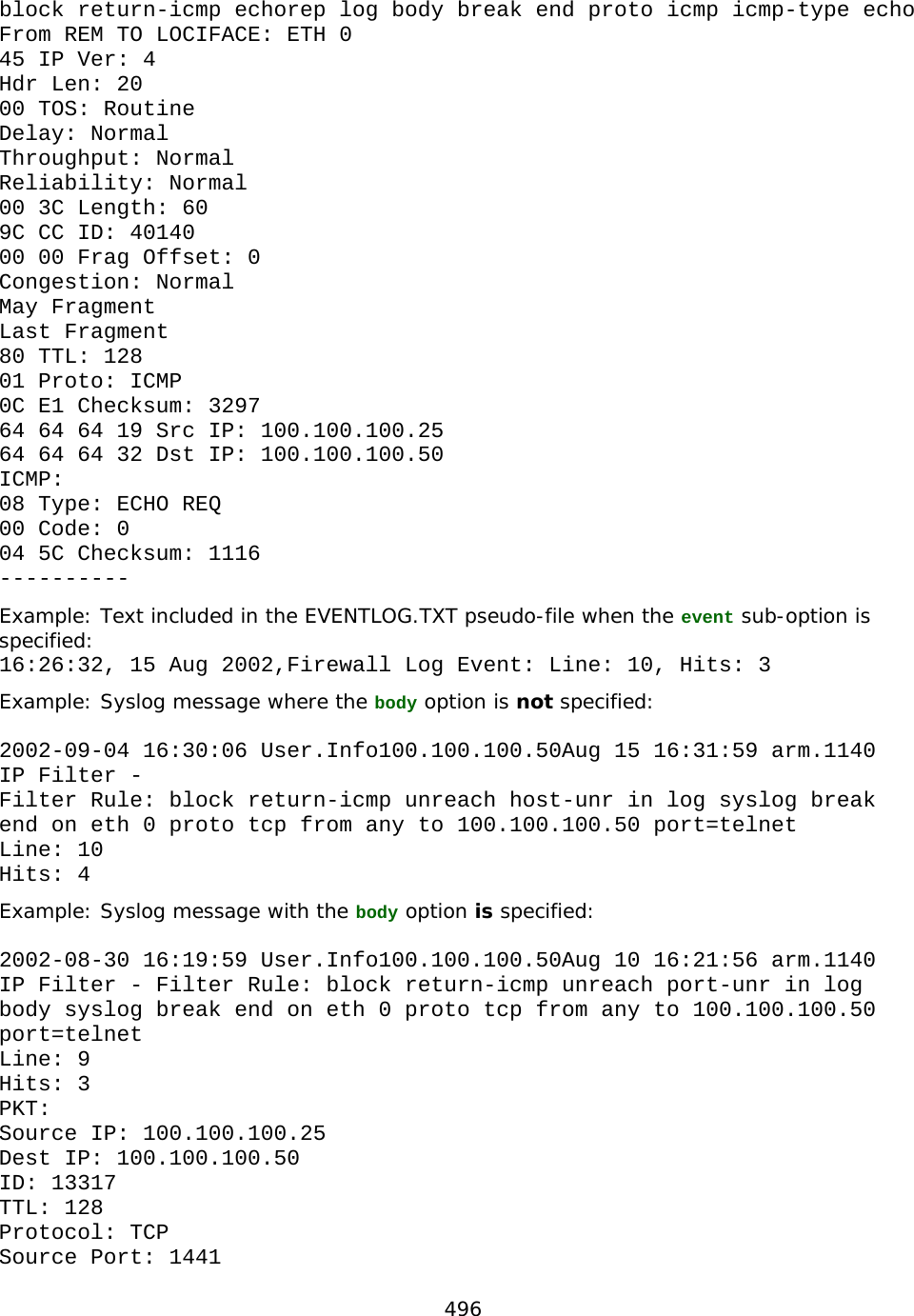
![483 The vdscp action is very similar to the dscp action as described above in that it adjusts the DSCP value in a packet. The difference however is that this is a virtual change only which means that the actual packet is not changed, and that the packet is processed as if it had the DSCP value as indicated. Like the dscp action, a decimal or hex number must follow. [in-out] The [in-out] field can be in or out and is used to specify whether the action applies to inbound or outbound packets. When the field is left blank the rule is applied to any packet irrespective of its direction. [options] The [options] field is used to define a number of options that may be applied to packets matching the rule. These are: log When the log option is specified, the unit will place an entry in the FWLOG.TXT file each time it processes a packet that matches the rule. This log will normally detail the rule that was matched along with a summary of the packet contents. If the log option is followed by the body sub-option, the complete IP packet is entered into the log file so that when the log file is displayed, a more detailed decode of the IP packet is shown. The log field may also be followed by a further sub-option that specifies a different type of log output. This may either be snmp, syslog or event. If snmp is specified an SNMP trap (containing similar information to the normal log entry), is generated when a packet matches the rule. If syslog is specified, a syslog message is sent to the configured syslog manager IP address. This message will contain the same information as that entered into the log file, but in a different format. If the body option has also been specified, some of the IP packet information is also included. Note that the size of the syslog message is limited to the maximum of 1024 bytes. The syslog message is sent with default priority value of 14, which expands out to facility of USER, and priority INFO. If event is specified the log output will be copied to the EVENTLOG.TXT pseudo-file as well as the FWLOG.TXT file. The event log entry will contain the line number and hit count for the rule that caused the packet to be logged. Example: Say your local network is on subnet 192.168.*.* and you want to block any packets received on PPP 0 that were “pretending” to be on the local network and log the receipt of any such packets to the FWLOG.TXT file and to a syslog server. The filter rule would be constructed as follows: block in log syslog break end on ppp 0 from 192.168.0.0/16 to any break When the break option is specified it must be followed by a user-defined label name or the predefined end keyword. When followed by a label, the rule processor will “jump” to that label to continue processing. When followed by the end keyword rule processing will be terminated and the packet will be treated according to the last matching rule.](https://usermanual.wiki/Digi/55M1644B.Manual-pt-1/User-Guide-1821845-Page-483.png)
![484 Example: break ppp_label on ppp 0 # insert rule processing here for packets that are not on ppp 0 break end ppp_label # insert rule processing here for packets that are on ppp 0 on The on option is used to specify the interface to which the rule applies and must be followed by a valid interface name. For example, if you were only interested in applying a particular rule to packets being transmitted or received by PPP 0, you would include on ppp 0 in the rule. Valid interface-names are either eth n, tun n or ppp n, where n is the instance number. oneroute The oneroute option is used to specify that a rule will only match packets associated with the specified eroute. For example, including the option oneroute 2 would cause the rule to only match on packets transmitted or received over Eroute 2. The oneroute option can be followed with the keyword any, which will match if the packet is on any eroute. routeto When the routeto option is specified and the firewall is processing a received packet, if the rule is the last matching rule, then the packet is tagged as being required to be routed to the specified interface. For example: pass in break end routeto eth 1 from 10.1.0.0/16 to 1.2.3.4 port=telnet would ensure that all packets from 10.1.*.* to 1.2.3.4 on the telnet port are all routed to ETH 1. oosed The oosed option is used to check the out of service status of an interface. For example, including the option oosed ppp 1 would cause the rule to match only if interface PPP 1 is out of service. [tos] The [tos] field may be used to specify the Type of Service (TOS) to match. If included, the [tos] field consists of the keyword tos followed by a decimal or hexadecimal code identifying the TOS to match. For example, to block any inbound packet on PPP 0 with a TOS of 0 you would use a rule such as: block in on ppp 0 tos 0 [proto] The [proto] field is used to specify a protocol to match and consists of the proto keyword followed by one of the following protocol identifiers: Identifier Meaning udp UDP packet tcp TCP packet](https://usermanual.wiki/Digi/55M1644B.Manual-pt-1/User-Guide-1821845-Page-484.png)
![485 Identifier Meaning ftp FTP packets regardless of port number icmp ICMP packet decimal number decimal number matched to protocol type in IP header The [proto] field is also important when “stateful” inspection is enabled for a rule (using the [inspect-state] field), as it describes the protocol to inspect (see [inspect-state] below). [dnslist] The [dnslist] field is used to match packets that contain DNS names that are in a given dnslist. Following dnslist there needs to be a name of a dnslist as specified by the #dns command. For example, say we have the following dnslist. #dns gglist www.Digi.co.*,www.*.co.nz Then the following firewall rule will block all dns lockups to DNS names matching the above list. block out break end on ppp 1 proto udp dnslist gglist from any to any port=dns [ip-range] The [ip-range] field is used to describe the range of IP addresses and ports to match upon and may be specified in one of several ways. The basic syntax is: ip-range = “all” | “from” ip-object “to” ip-object [flags] [icmp] where ip-object is an IP address specification. Full details of the syntax with examples are given under the heading “Specifying IP Addresses and Address Ranges” below. [inspect-state] The [inspect-state] field is used in create rules for “stateful inspection”. This is a powerful option in which the firewall script includes rules that allow the unit to keep track of a TCP/UDP or ICMP session and therefore to only pass packets that match the state of a connection. Additionally, the [inspect state] field can specify an optional OOS (Out Of Service) parameter. This parameter allows the unit to mark any route as being out-of-service for a given period of time in the event that the stateful inspect engine has detected an error. A full description of how the [inspect state] field works is given below under the heading “Stateful Inspection”. Specifying IP Addresses and Ranges The ip-range field of a firewall script rule identifies the IP address or range of addresses to which the rule applies. The syntax for specifying an IP address range is: ip-range = “all” | “from” ip-object “to” ip-object [ flags ] [ icmp ] where: ip-object = addr [port-comp | port-range] flags = “flags” { flags } [ !{ flags } ] icmp = “icmp-type” icmp-type [ “code” decnum ] addr = “any” | ip-addr[ “/”decnum ] [ “mask” ip-addr | “mask” hexnum ]](https://usermanual.wiki/Digi/55M1644B.Manual-pt-1/User-Guide-1821845-Page-485.png)
![487 Address/Port Translation One further option that may be used when specifying addresses is to use address translation. The syntax for this is: srcdst = “all | fromto [-> [ip-object] “to” object] I.e. directly after the IP addresses and port are specified an optional “->” can follow indicating that the addresses/ports should be translated. The first source object is optional and is unlikely to be used as it is more normal to translate the destination address. The following example will reroute packets originally destined for 10.10.10.12 to 10.1.2.3: pass out break end from any to 10.10.10.12 -> to 10.1.2.3 Additionally to this complete subnets can have NAT applied, the address bits not covered by the subnet mask are taken from the original IP address, so for example to NAT the destination subnet of 192.168.0.0/24 to be 192.168.1.0/24 the firewall rule is: pass out break end from any to 192.168.0.0/24 -> to 192.168.1.0/24 Filtering on Port Numbers Now let us say there is a Telnet server running on a machine on IP address 10.1.2.63 and you wish to make this accessible. Using the filter from the previous example would block all packets to 10.1.2.*. To make the Telnet server available on 10.1.2.63 we need to add the following line in front of the blocking rule: pass break end from any to 10.1.2.63 port=23 So, a packet being sent to the Telnet server (port 23) on IP address 10.1.2.63 will match this rule and further checking is prevented by the break end option. The above example illustrates the “=” comparison. Other comparison methods supported are: Symbol Meaning != not equal > greater than < less than <= less than or equal to >= greater than or equal to It is also possible to specify a port in range or a port out of range with the “><” or “<>” symbols. For example, to pass all packets to addresses in the range 23 to 28, the rule would be specified as: pass break end from any to 10.1.2.63 port 23><28 To simplify references to ports, some commonly used port numbers are associated with the predefined strings listed in the table below. For instance, in the example above we could substitute the number 23 with the string telnet. This would make the rule: pass break end from any to 10.1.2.63 port=telnet The other port keywords that are defined are: Keyword Std. Port Service Ftpdat 20 File Transfer Protocol data port Ftpcnt 21 File Transfer Protocol control port](https://usermanual.wiki/Digi/55M1644B.Manual-pt-1/User-Guide-1821845-Page-487.png)
![488 Keyword Std. Port Service telnet 23 Telnet server port smtp 25 SMTP server port http 80 Web server port pop3 110 Mail server port sntp 123 NTP server port ike 500 Source/destination port for IKE key xot 1998 Destination port for XOT packets Note: The above service keywords are pre-defined based on “standard” port numbers. It is possible that these may have been defined differently on your system in which case you should use the port numbers explicitly (not the defined names). Filtering on TCP Flags An ip-object can be followed by an optional [flags] field. This field allows the script to filter based on any combination of TCP flags. The [flags] field is used to specify the flags to check and consists of the flags keyword followed by a string specifying the flags themselves. Each letter in this string represents a particular flag type as listed below: Code Flag f FIN Flag r RESET Flag s SYN Flag p PUSH Flag u URG Flag a ACK Flag These flag codes allow the filter to check any combination of flags. Following on from the previous example, to block packets that have all the flags set you would need to precede the pass rule with the following block rule: block break end from any to 10.1.2.0/24 port=telnet flags frspua Here, the list of flags causes the unit to check that those flags are set. This list may be optionally followed by an exclamation mark (“!”) and a second list of flags that the unit should check for being clear. For example: flags s!a would test for the s flag being on and the a flag being off with all other flags ignored.](https://usermanual.wiki/Digi/55M1644B.Manual-pt-1/User-Guide-1821845-Page-488.png)
![489 As a further example, let us say we want to allow outward connections from a machine on 10.1.2.33 to a Telnet server. We have to define a filter rule to pass outbound connections and the inbound response packets. Because this is an outbound Telnet service we can make use of the fact that all incoming packets will have their ACK bits set. Only the first packet establishing the connection will have the ACK bit off. The filter rules to do this would look like this: pass out break end from 10.1.2.33 port>1023 to any port=telnet pass in break end from any port=telnet to 10.1.2.33 port>1023 flags !a The first rule allows the outward connections, and the second rule allows the response packets back in which the ACK flag must always be on. This second rule will filter out any packets that do not have the ACK flag on. This will bar any attackers from trying to open connections onto the private network by simply specifying the source port as the Telnet port (note that there is a simpler way to achieve the same effect using the inspect state option described below). Filtering on ICMP Codes An ip-object can be followed by an optional [icmp] field. This allows the script to filter packets based on ICMP codes. ICMP packets are normally used to debug and diagnose a network and can be extremely useful. However they form part of a low-level protocol and are frequently exploited by hackers for attacking networks. For this reason most network administrators will want to restrict the use of ICMP packets. The syntax for including ICMP filtering is: icmp = “icmp-type” icmp-type [“code” decnum] The icmp-type can be one of the pre-defined strings listed in the following table or the equivalent decimal numeric value: ICMP Type ICMP Value Unreach 3 Echo 8 Echorep 0 Squench 4 Redir 5 Timex 11 Paramprob 12 Timest 13 Timestrep 14 Inforeq 15 Inforep 16 Maskreq 17 Maskrep 18 Routerad 9 Routersol 10](https://usermanual.wiki/Digi/55M1644B.Manual-pt-1/User-Guide-1821845-Page-489.png)
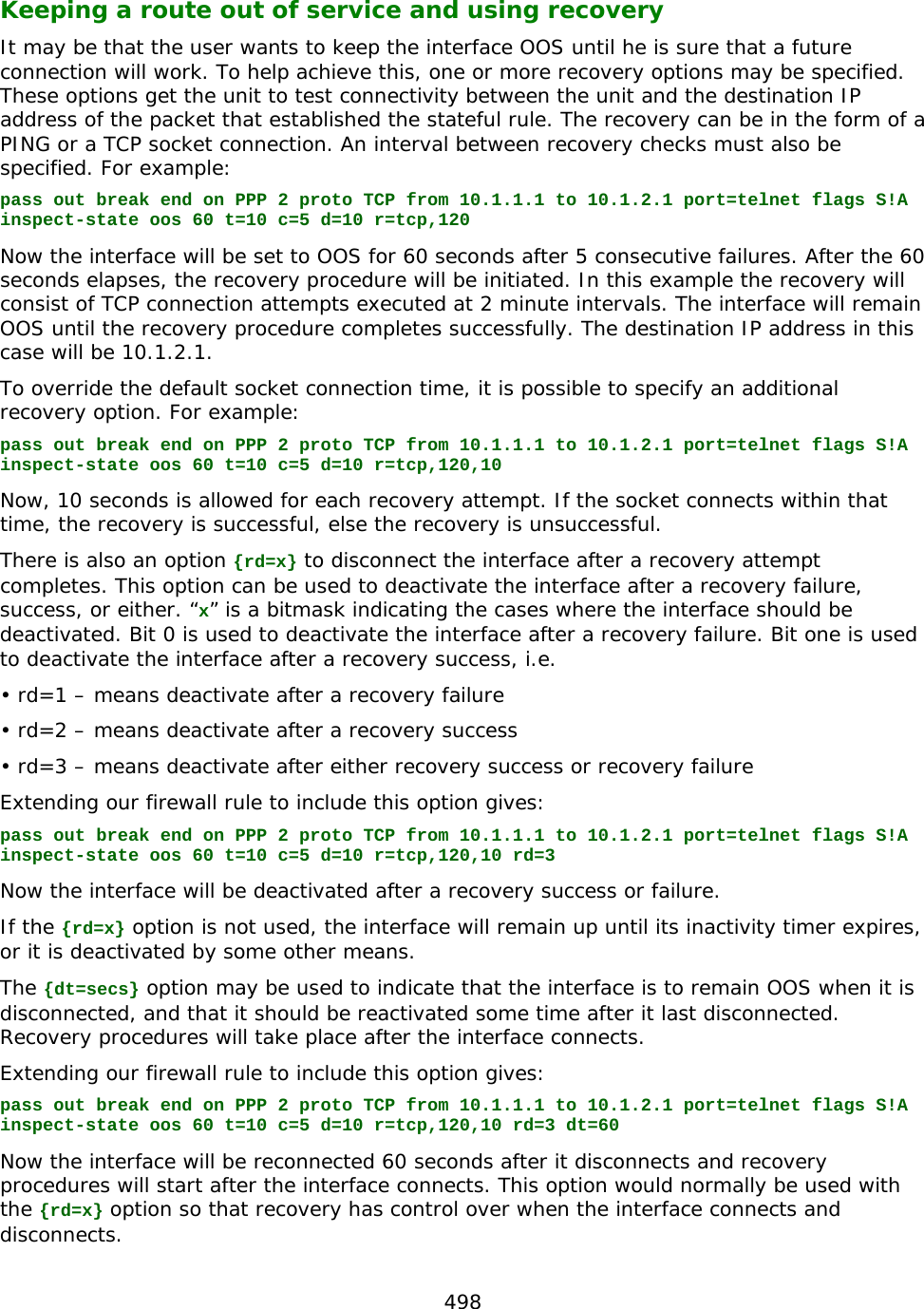
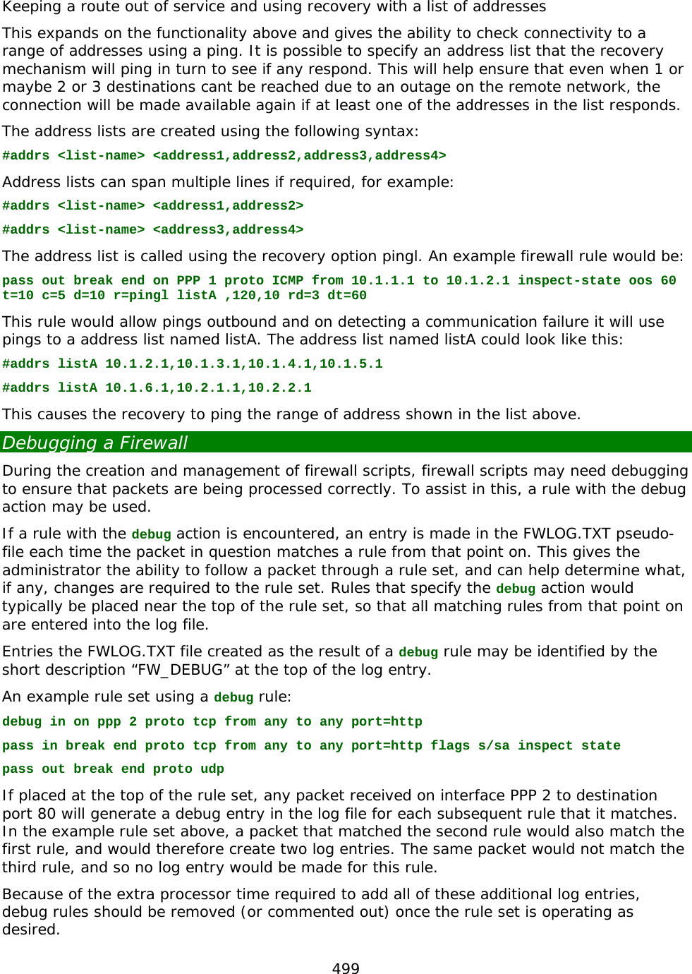
![490 The following two rules are therefore equivalent: pass in break end on ppp 0 proto icmp from any to 10.1.2.0/24 icmp-type 0 pass in break end on ppp 0 proto icmp from any to 10.1.2.0/24 icmp-type echorep Both of these rules allow echo replies to come in from interface ppp 0 if they are addressed to our example local network address (10.1.2.*). In addition to having a type, ICMP packets also include an ICMP code field. The filter syntax allows for the specification of an optional code field after the ICMP type. When specified the code field must also match. The ICMP code field is specified with a decimal number. For example, suppose we wish to allow only echo replies and ICMP unreachable type ICMP packets from interface PPP 0. Then the rules would look something like this: pass in break end on ppp 0 proto icmp from any to 10.1.2.0/24 icmp-type echorep code 0 pass in break end on ppp 0 proto icmp from any to 10.1.2.0/24 icmp-type unreach code 0 block in break end on ppp 0 proto icmp The first two rules in this set allow in the ICMP packets that we are willing to permit and the third rule denies all other ICMP packets in from this interface. Now if we ever expect to see echo replies in on ppp 0 we should allow echo requests out on that interface too. To do that we would have the rule: pass out break end on ppp 0 proto icmp icmp-type echo Stateful Inspection The Digi routing code stack contains a sophisticated scripted “Stateful Firewall” and “Route Inspection” engine. Stateful inspection is a powerful tool that allows the unit to keep track of a TCP/UDP or ICMP session and match packets based on the state of the connection on which they are being carried. In addition to providing sophisticated Firewall functionality the SF/RI engine also provides a number of facilities for tracking the “health” of routes, marking “dead” routes as being Out Of Service (OOS) and creating rules for the automatic status checking of routes previously marked as OOS (for use in multilevel backup/restore scenarios). The firewall may be used to place interface into an OOS state and also control how the interfaces return to service. When an interface goes OOS, all routes configured to use that interface will have their route metric set to 16 (the maximum value), meaning that some other route with a lower metric will be selected. When a firewall stateful inspection rule expires, a decision is made as to whether the traffic being allowed to pass by this rule completed successfully or not. For example, if the stateful rule monitors SYN and FIN packets in both directions for a TCP socket then that rule will expire successfully. However, if SYNs are seen to pass in one direction but no SYNs pass in the other direction, the stateful rule will expire and the unit will tag this as a failure. The following conditions tag a stateful rule as a failure: • packets have only passed in one direction • 10 packets have passed in one direction with no return packets (for TCP the packets must also be re-transmits) All of these features depend upon the stateful inspection capabilities of the Firewall engine which are explained below. The [inspect] field takes the following format: inspect = [“inspect-state” {“oos” {interface-name¦logical-name} secs {t=secs} {c=count} {d=count}} {r=“ping”¦“tcp”{,secs{secs}}} {rd=x} {dt=secs}{stat}]](https://usermanual.wiki/Digi/55M1644B.Manual-pt-1/User-Guide-1821845-Page-490.png)
![492 The potential for a security breach has now been virtually eliminated because even if a hacker could time his attack perfectly he would still have to forge a response packet using the correct source address and port (which was randomly created by the sender of the HTTP request) and also has to target the specific IP address that opened the connection. Another advantage of “inspect-state” rules is that they are scalable, i.e. many machines can use the rule simultaneously. In our above example for instance many machines on the local network could all browse the Internet and the inspection engine would be dynamically creating precise inward filters as they are required and closing them when they are finished with. The inspect-state option can be used on TCP, UDP protocols and some ICMP packets. The ICMP types that can be used with the “inspect-state” option are “echo”, “timest”, “inforeq” and “maskreq”. Using [inspect-state] with Flags As can be seen above, the inspect-state option can be used with flags. To illustrate this we will refer back to the earlier example of filtering using flags. It is possible to simplify the script by using the inspect-state option. The original script was: pass out break end from 10.1.2.33 port>1023 to any port=telnet pass in break end from any port=telnet to 10.1.2.33 port>1023 flags a! Using the inspect state option this can be replaced with a single filter rule: pass out break end from 10.1.2.33 port>1023 to any port=telnet flags s!a inspect-state No rule is needed for the return packets because a temporary filter will be created that will only allow inbound packets to pass if they match sessions set up by this stateful inspection rule. A further point to note about the new rule is that the “flags s!a” specification ensures that it only matches the first packet in a connection. This is because the first packet in a TCP connection has the SYN flag on and the ACK flag off and so we only match on that combination. The stateful inspection engine will take care of matching the rest of the packets for this connection. Using [inspect-state] with ICMP The [inspect-state] option can be also used with ICMP codes. To allow the use of echo request and to allow echo replies you would have just the one rule: pass out break end on ppp 0 proto icmp icmp-type echo inspect-state The advantage of using inspect-state, other than just needing one rule, is that it leads to a more secure firewall. For instance with the inspect-state option the echo replies are not allowed in all the time; they will only be allowed in once an echo request has been sent out on that interface. The moment that a valid echo reply comes back (or there is a timeout), echo replies will again be blocked. Furthermore, the full IP address is checked; the IP source and destination must exactly match the IP destination and source of the echo request. If you compare this to the rule to allow echo replies in without using inspect-state it would not be possible to check the source address at all and the destination address would match any IP address on our network.](https://usermanual.wiki/Digi/55M1644B.Manual-pt-1/User-Guide-1821845-Page-492.png)
![493 The inspect-state option can be used with the following ICMP packet types: ICMP Type Matching ICMP Type Echo Echo reply Timest Timestrep Inforeq Inforep Maskreq Maskrep Using [inspect-state] with the Out Of Service Option The inspect-state field can be used with an optional oos parameter. This parameter allows the stateful inspect engine to mark as “out of service” any routes that are associated with the specified interface and also to control how and the interfaces are returned to service. Such routes will only be marked as out of service if the specified oos option parameters are met. The oos parameter takes the format: oos {interface-name¦logical-name} secs {t=secs} {c=count} {d=count} {r=“ping”|“tcp”{,secs}} where: interface-name or logical-name specifies the interface with which the firewall rule is associated, e.g. PPP 1. This can also be a logical interface name which is simply a name that can be created (e.g. “waffle”). When a logical interface name is specified then this name can become oos (out of service) and can be tested in other firewall rules with the oosed keyword. secs specifies the length of time in seconds for which the routes that are using the specified interface are marked as out of service. {t=secs} is an optional parameter that specifies the length of time in seconds the unit will wait for a response the packet that matched the rule. {c=count} is an optional parameter that specifies the number of times that the stateful inspection engine must trigger on the rule before the route is marked as out of service. {d=count} is an optional parameter that specifies the number of times that the stateful inspection engine must trigger on the rule before the interface is deactivated (only applies to PPP interfaces). {r=“ping”|“tcp”{,secs{,secs}}} is an optional parameter that specifies a recovery procedure. When a recovery procedure is specified then after the oos timeout has expired instead of bringing the interface back into service immediately the link is tested first. It is tested by either sending a TCP SYN packet or a ping packet to the address/port that caused the oos condition. The “secs” field specifies the retry time when checking for recovery. Only when the recovery succeeds will interface become in service again. UDP Example pass in pass out pass out on ppp 1 proto udp from any to 156.15.0.0/16 port=1234 inspect-state oos ppp 1 300 t=10 c=2 d=2 The first two rules simply configure the unit to allow any type of packets to be transmitted or received (the default action of the firewall is to block all traffic).](https://usermanual.wiki/Digi/55M1644B.Manual-pt-1/User-Guide-1821845-Page-493.png)
![494 The third rule is more complex. What it does is to configure the stateful inspection engine to watch for UDP packets (with any source address) being routed via the PPP 1 interface to any address that begins with 156.15 on port 1234. If a hit occurs on this rule but the unit does not detect a reply within 10 seconds (as specified by the t= parameter), it will increment an internal counter. When this counter reaches the value set by the c= parameter, the stateful inspection engine will mark the PPP 1 interface (and therefore any routes using it), as being out of service for 300 seconds. Similarly, if this counter matches the d= parameter the stateful inspection engine will deactivate PPP 1. So in the above example, the stateful inspection engine will mark any routes that use PPP 1 as out of service AND deactivate PPP 1 if no reply is detected within 10 seconds for two packets in a row. Routes will come back into service when either the specified timeout expires or if there are no other routes with a higher metric in service. PPP interfaces will be re-activated when either the routes using them are back in service and there is a packet to route and the AODI mode parameter is set to “On”. TCP Example pass out log break end on ppp 3 proto tcp from any to 192.168.0.1 flags S!A inspect-state oos 30 t=10 c=2 d=2 pass in pass out This rule will specifically trace attempts to open a TCP connection on PPP 3 to the 192.168.0.1 IP address and if it fails within 10 seconds twice in a row, will cause the PPP 3 interface to be flagged as out of service (i.e. its metric will be set to 16), for 30 seconds. The optional d=2 entry will also cause the PPP link to be deactivated. Deactivating the link can be useful in scenarios where renegotiating the PPP connection is likely to resolve the problem. Again, if a matching route with a higher metric has been defined it will be used whilst PPP 3 routes are out of service thus providing a powerful route backup mechanism. Using [inspect-state] with the Stat Option The inspect-state option can be used with the stat option. The stat option will cause this firewall rule to record statistics associated with this firewall rule. Transaction times, counts and errors are recorded under the PPP statistics with this option. Assigning DSCP Values When using QOS, packet priorities will be determined by the DSCP values in their TOS fields. These priorities may have already been assigned but if necessary, the router can be configured to assign them by inserting the appropriate rules in the firewall. This is done by using the dscp command. For example: dscp 46 in on eth 0 from 100.100.100.25 to 1.2.3.4 port=4000 would set the DSCP value to 46 for almost any type of packet received on ETH 0 from IP address 100.100.100.25 addressed to 1.2.3.4 on port 4000. This allows you to set the DSCP value for almost any type of packet. As a further example: dscp 46 in on eth 0 proto smtp from any to any would cause outgoing mail traffic to the same top priority queue (46 is by default a very high priority code in the DSCP mappings).](https://usermanual.wiki/Digi/55M1644B.Manual-pt-1/User-Guide-1821845-Page-494.png)
![497 Dest Port: 23 TCP Flags: S Further [inspect-state] Examples Here is a basic inspect-state rule with no OOS options: pass out break end on PPP 2 proto TCP from 10.1.1.1 to 10.1.2.1 port=telnet flags S!A inspect-state This rule will allow TCP packets from 10.1.1.1 to 10.1.2.1 port 23 with the SYN flag set to pass out on PPP 2. Because the inspect-state option is used, a stateful rule will also be set up which allows other packets for that TCP socket to also pass. Next, we will modify the rule to mark an interface OOS if a stateful rule identifies a failed connection: pass out break end on PPP 2 proto TCP from 10.1.1.1 to 10.1.2.1 port=telnet flags S!A inspect-state oos 60 The addition of oos 60 means that if the stateful rule sees a failure, interface PPP 2 will be set OOS for 60 seconds. If no interface is specified after the oos keyword, the interface set to OOS will be the one the packet is currently passing on. It is possible to OOS a different interface by specifying the interface after the oos keyword, e.g. oos ppp 1 60 to put PPP 1 out of service for 60 seconds. The default time allowed by the stateful rule for a connection to open may be overridden by using the {t=secs} option. E.g. To override the default TCP opening time of 60 seconds to 10 seconds: pass out break end on PPP 2 proto TCP from 10.1.1.1 to 10.1.2.1 port=telnet flags S!A inspect-state oos 60 t=10 A socket will now only have 10 seconds to become established (i.e. exchange SYNs) before the stateful rule will expire and be tagged as a failure. It is possible to configure the firewall so that the interface is only set to OOS after a number of consecutive failures occur. To do this, use the {c=count} option. For example: pass out break end on PPP 2 proto TCP from 10.1.1.1 to 10.1.2.1 port=telnet flags S!A inspect-state oos 60 t=10 c=5 PPP 2 will now only be set OOS after 5 consecutive failures. It is possible to deactivate the interface after a number of consecutive failures. This is useful for WWAN interfaces, which may get into a state where the PPP connection appears to be operational, but in fact no packets are passing. In this case, deactivating and reactivating the interface will sometimes fix the problem. For example: pass out break end on PPP 2 proto TCP from 10.1.1.1 to 10.1.2.1 port=telnet flags S!A inspect-state oos 60 t=10 c=5 d=10 Now, PPP 2 will be deactivated after 10 consecutive failures.](https://usermanual.wiki/Digi/55M1644B.Manual-pt-1/User-Guide-1821845-Page-497.png)

![518 REBOOT Reboot Unit The reboot command causes the unit to execute a complete hardware reset, loading and running the main image file from cold. It has three modes of operation: reboot - will reboot the unit after any FLASH write operations have been completed. Also, 1 second each is allowed for the following operations to be completed before reboot will take place: • IPSec SA delete notifications have been created and sent • TCP sockets have been closed • PPP interfaces have been disconnected reboot <n> - will reboot the unit in <n>minutes where n is 1 to 65,535 reboot cancel - will cancel a timed reboot if entered before the time period has passed. Reset router to factory defaults See reference guide section titled “Administration - Factory Default Settings”. Disabling the reset button Normally when the reset button is held in for 5 seconds the router is reset to factory defaults. The factory reset button functionality can be disabled / enabled if required. The command to disable the reset button is “cmd 0 pbreset off” To re-enable the reset button functionality “cmd 0 pbreset on” TEMPLOG Temperature monitoring The on-board temperature sensors are sampled every 60 seconds and any 'interesting' changes in the temperature are logged to a special flash file, 'templog.c1'. Use 'templog 0 status' to view the last stored record in this file. There are 2 sensors built in, there is one on the motherboard and one on the modem module. If a temperature is reached that is outside of normal operating limits, an event will be logged in the eventlog.txt Note: The only transport models that support TEMPLOG are DR64 and VC7400. Ping and Traceroute From the CLI, these commands can be used to help troubleshoot connectivity problems. The syntax of the ping command is: ping <ip address|FQDN> [n] Where n (if used) is the number of ICMP echo requests to send. If not specified, only 1 echo request will be sent. To stop pings when n has been set to a high value use ping stop The syntax of the traceroute command is: traceroute <ip address|FQDN> To stop a failed trace if hosts can not be detected, use traceroute stop](https://usermanual.wiki/Digi/55M1644B.Manual-pt-1/User-Guide-1821845-Page-518.png)
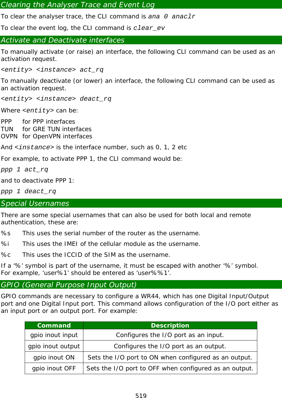
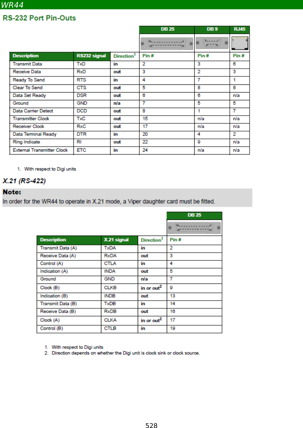
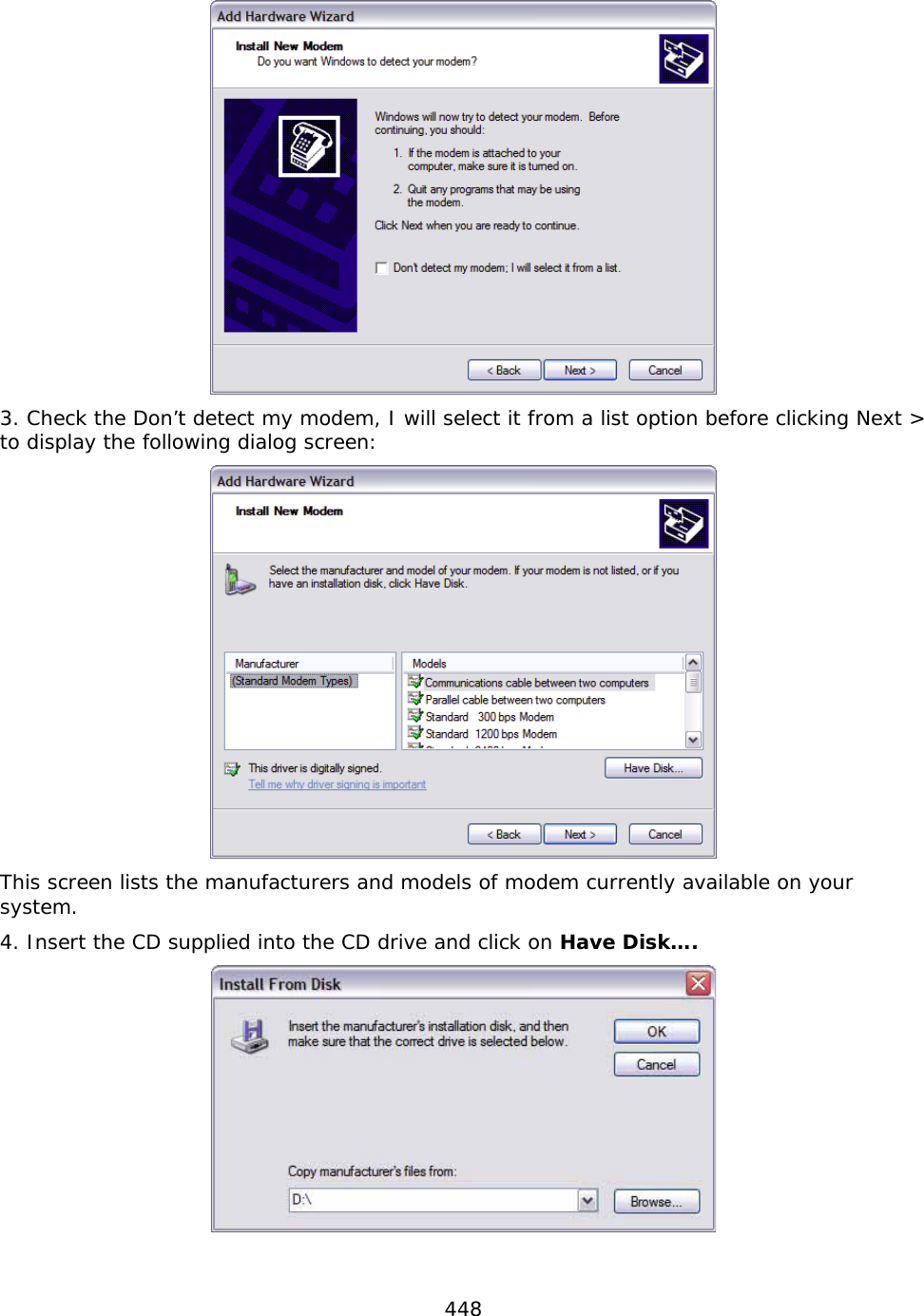
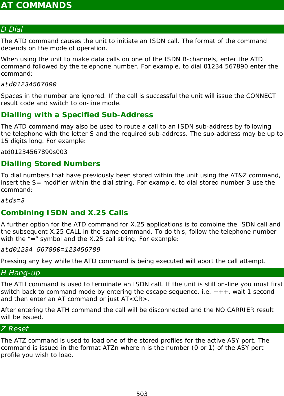
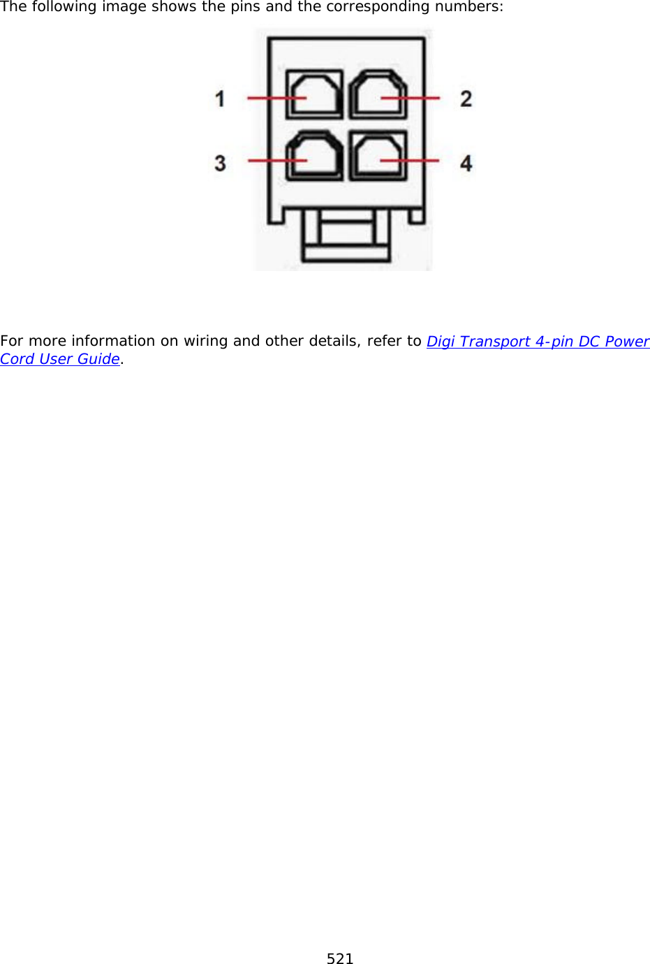
![520 The syntax of the command is as follows: Usage: gpio [inout ON|OFF|input|output] With no parameters, the command will display the current status of the ports. For example: gpio Input(s): in : OFF Output(s): inout : OFF OK To set the I/O port to be an output: gpio inout output Input(s): in : OFF Output(s): inout : OFF OK To set the I/O port to ON when it is configured as an output: gpio inout on Input(s): in : OFF Output(s): inout : ON OK The Input and Input/Output connections (pins 2 and 3) are programmed via the command line using the gpio command. The default setting for pins 2 and 3 are OFF as seen in the above example. Note: Only one of the power connectors should be used. Never apply power to both the MAIN and AUX connectors at the same time. Pin Description Pin 1 GROUND Pin 2 INPUT Pin 3 Input/ Output Pin 4 Power](https://usermanual.wiki/Digi/55M1644B.Manual-pt-1/User-Guide-1821845-Page-520.png)
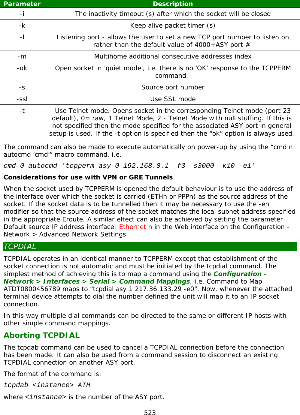
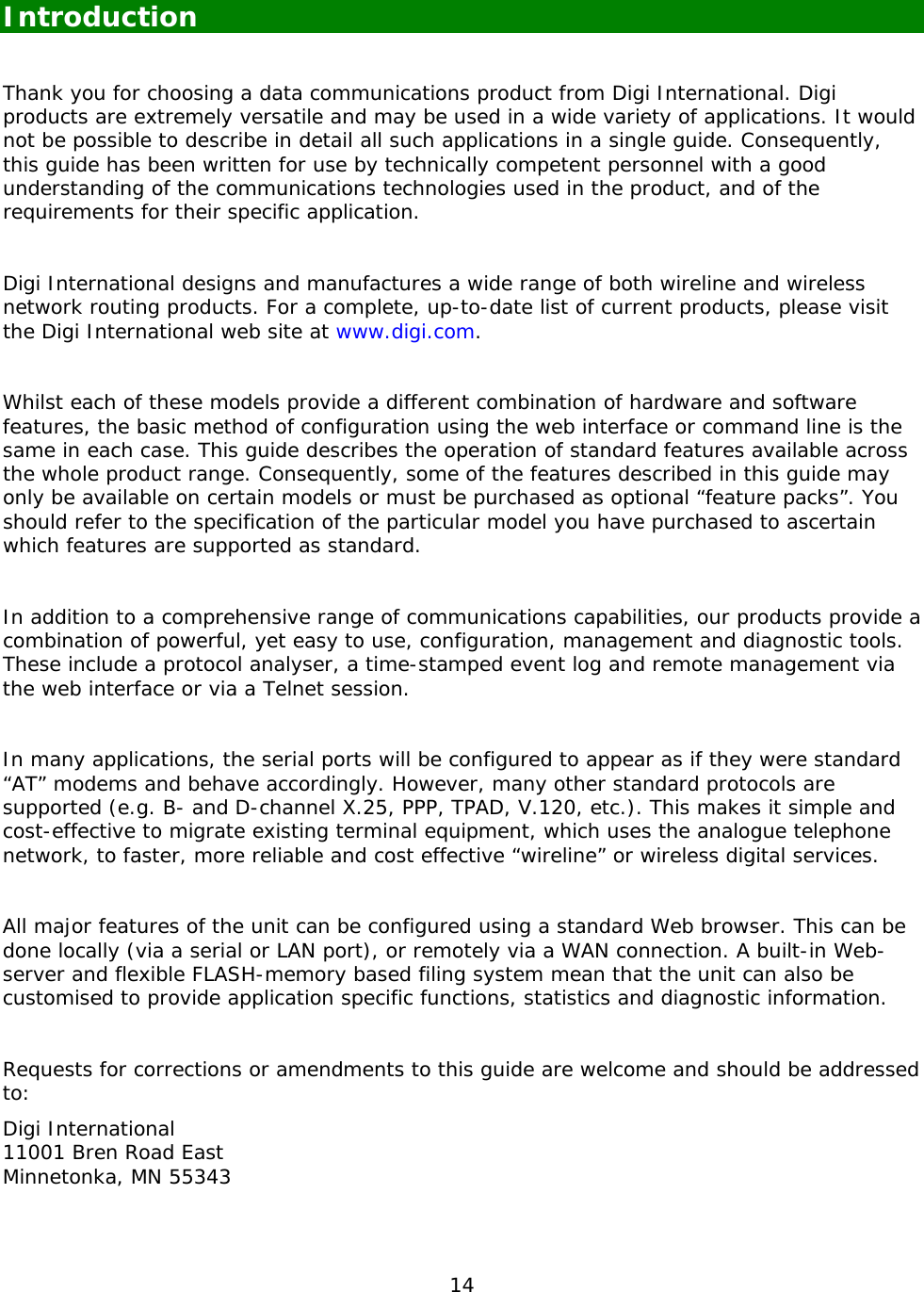
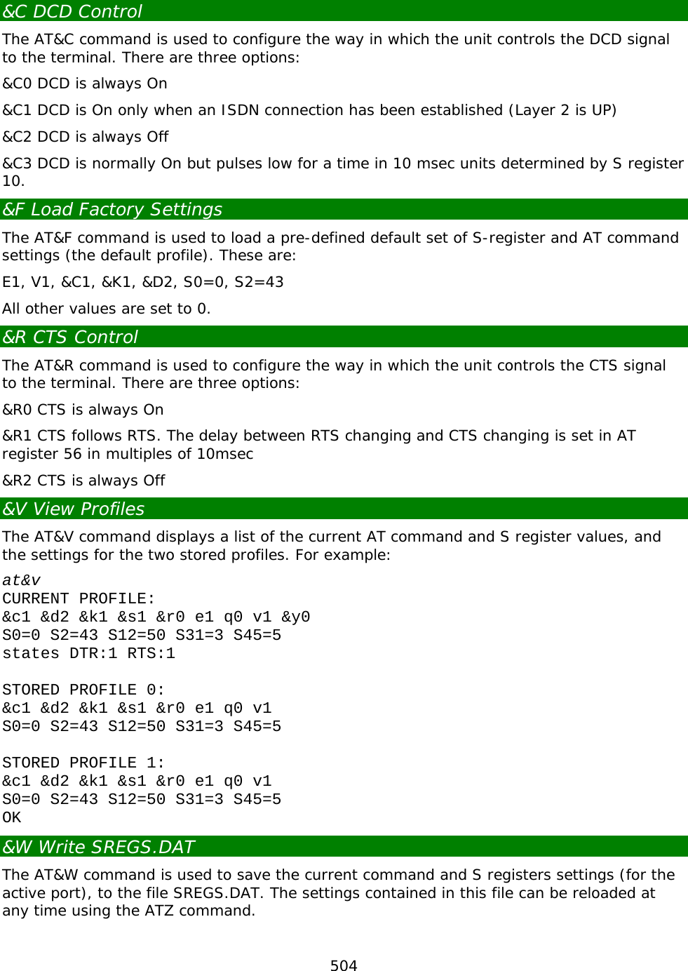
![522 TCPPERM AND TCPDIAL This section describes the operation of the tcpperm and tcpdial commands which are available only as application commands and have no equivalent web pages. TCPPERM The tcpperm command is used to establish a permanent “serial to IP” connection between one of the ASY ports and a remote IP host. After the command has been executed, the unit will automatically open a socket connection to the remote peer whenever data is received from a terminal attached to the specified ASY port. When the socket is first opened and the connection has been established, the unit will issue a CONNECT message to the terminal and will subsequently relay data between the socket and the ASY port. The format of the CONNECT message can be modified using the standard AT commands (e.g. ATV, ATE, etc.) or using the Configuration - Network > Interfaces > Serial > Serial Port n web page. Note: The serial port should also be pre-configured to use the appropriate word format, speed and flow control. While the serial-to-IP connection is established, if the attached serial device drops the DTR signal, then the socket connection will be terminated, much as with a standard modem or terminal adapter. Again this behaviour can be modified via the AT&D command or the serial port settings. The format of the command is: TCPPERM <[ASY 0-1]> <Dest Host> <Dest Port> [UDP] [nodeact] [-l<listening port>] [-i<inact_timeout>] [-f<fwd_time>] [-e<eth_ip>][-d(deact link)] [-k<keepalive_time>] [-s<src_port>] [-ok] [-t<telnet_mode>] [-ho(host only)] [-ssl] [-ao(always open)] [-m<mhome idx>] The parameters are detailed in the following table: Parameter Description ASY The number of the ASY port that the link will be made from/to Dest Host The IP address (or name) of the remote peer Dest Port The port number to use on the remote peer UDP Open a UDP connection (the default is TCP) -ao Open socket immediately, and reopen if and when the socket is closed -e Use the address of ethernet port ’n’ for the socket connection rather than the default of the address of the interface over which the socket is opened (i.e ppp 1, ppp 2, etc.) -d Deactivate link - if non-zero, when the socket is closed and there are no other sockets using the interface then the interface connection is dropped (switched connections only) -f The forwarding time (x10ms) for packetising data from the serial port -ho Host - indicates that the socket should only accept connections from the specified host.](https://usermanual.wiki/Digi/55M1644B.Manual-pt-1/User-Guide-1821845-Page-522.png)