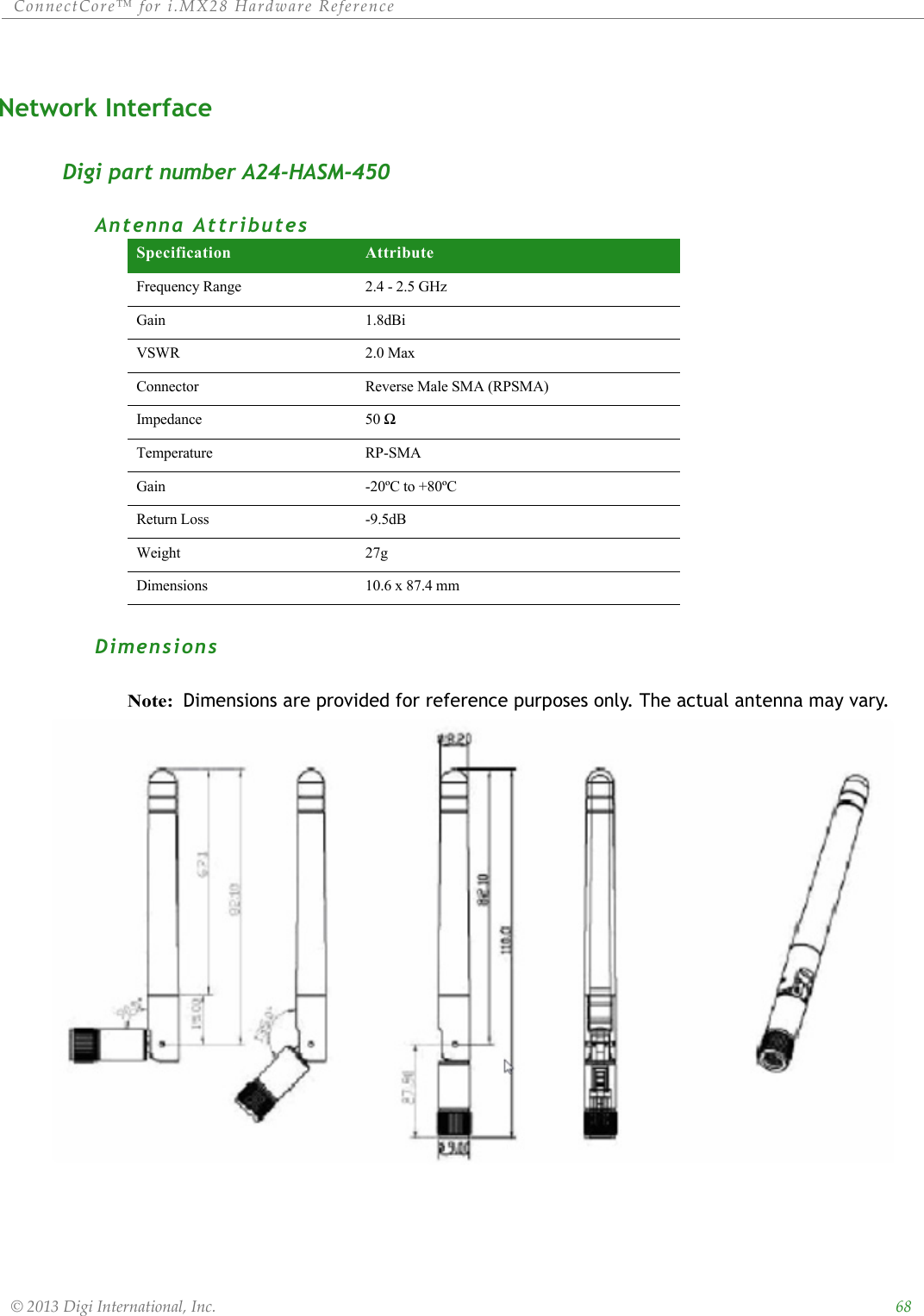
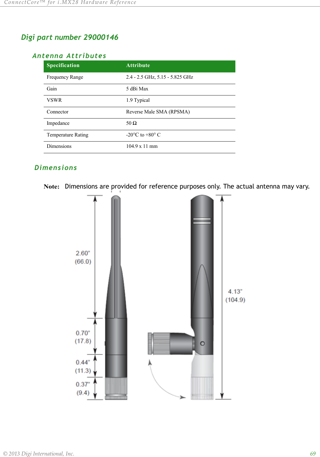
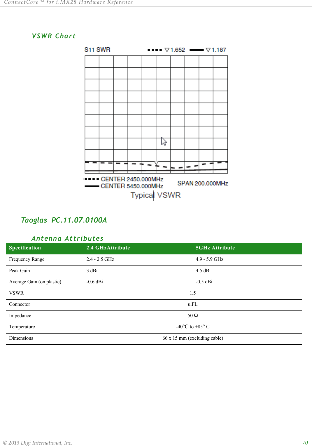
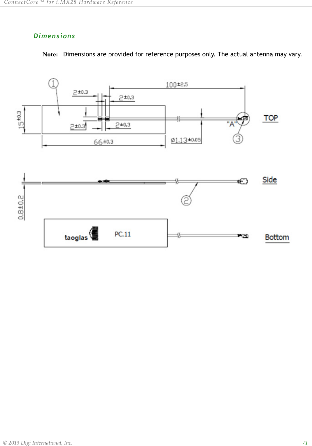
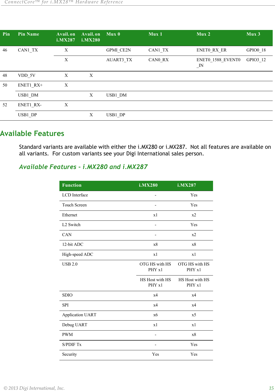
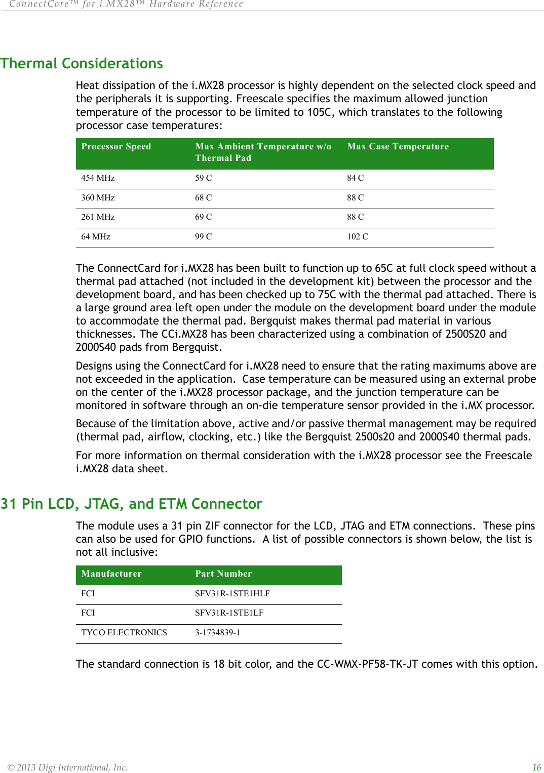
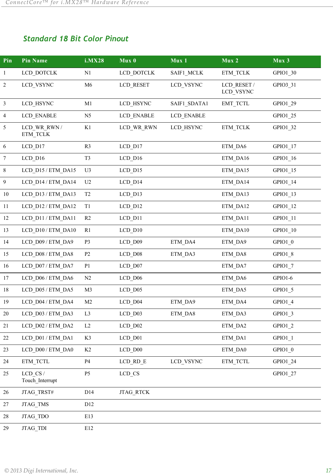
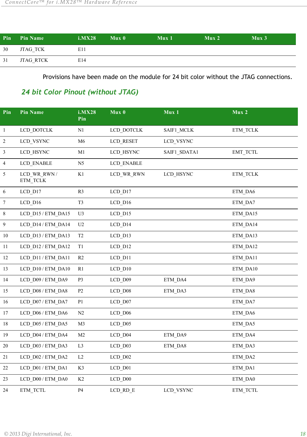
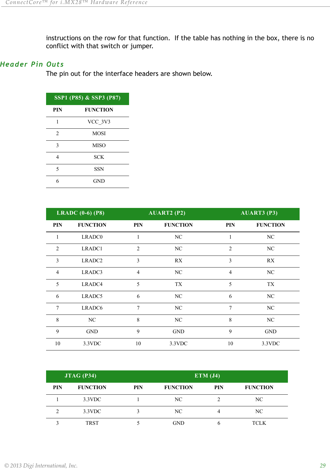
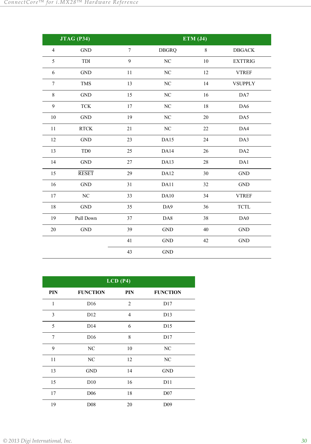
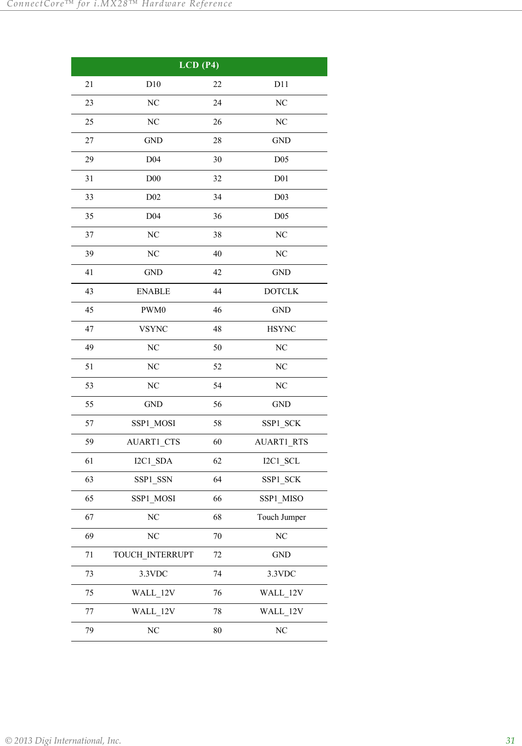
Digi CCIMX28 802.11a/b/g/n Embedded Client Module User Manual ConnectCore for i MX28 HRM
Digi International Inc 802.11a/b/g/n Embedded Client Module ConnectCore for i MX28 HRM
UserManual.wiki
>
Digi
>
CCIMX28 User Manual
>
Hardware Reference
Contents
1.
Hardware Reference
2.
Manual
Hardware Reference
Navigation menu
Upload a User Manual
Namespaces
Wiki Guide
HTML
PDF
Info
Views
User Manual
Discussion / Help
Navigation

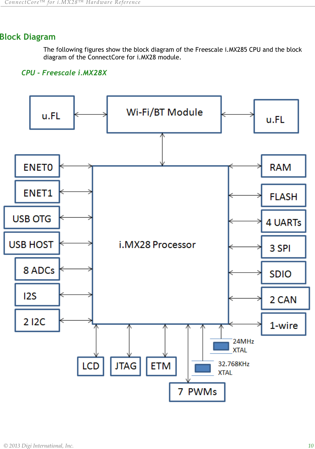
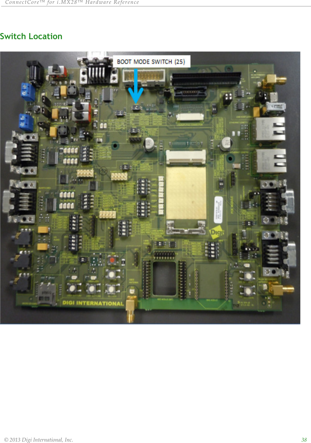
![ConnectCore™ for i.MX28™ Hardware Reference © 2013 Digi International, Inc. 20code uses the state of the internal register BOOT_MODE[1:0] as well as the state of various eFUSEs and/or GPIO settings to determine the boot flow behavior of the module.The following Boot modes are supported:Boot from FLASHBoot from SD CardBoot from USBBoot from JTAGEach mode is selected by applying the proper bit pattern to LCD_D00, LCD_D01, LCD_D02, LCD_D03, and LCD_D04. The default boot mode is FLASH. No internal eFUSEs have been set. For more information on boot modes, please refer to chapter 12 of the Freescale documentation.Audio SystemThe audio system is using an SAIF interface configured as I2S.LCD SystemThe LCD is available through a 31 pin ZIF connector on the top side of the module (see variants for availability). The development kit uses a cable from NICOMATIC (part number 050P331K0076-406406 ). The default LCD setting is for 18 bit color, and the development board is set up for this setting as well. A special 24 bit color option is available (not supported in current variant list) but will disconnect the JTAG functionality. Touch screen functionality is supported by connecting LRADC2-5. There are multiple SPI ports available to communicate with a SPI touch screen controller (the development board uses SSP1). PWM0,1,3,4,5 and 6 are available to use for backlight control (the development board uses PWM0).GPIOIn general any of the modules digital pins can be set as a GPIO. There are 3 available states for any GPIO-- low, high , and high impedance. Each of the GPIO pins is capable of functioning on either at 1.8 or 3.3V as well as an interrupt/trigger pin. Each individual GPIO can be dynamically programmed at any time to be in either: High-impedance (for input, three-state, or open-drain applications); Low; High; or Controlled by one of the three selectable i.MX28 peripheral module interfaces. The state of any GPIO pin can be read at any time regardless of its configuration. Analog pins may not be set as GPIO. The following functions cannot be used for GPIO functions:EthernetUSBLRADC (although muxed functions can be used)HSADCOne Wire (Technically it could be by controlling the I2C line)JTAG](https://usermanual.wiki/Digi/CCIMX28.Hardware-Reference/User-Guide-1956052-Page-20.png)


![© 2013 Digi International, Inc. 61CertificationsCHAPTER 3Agency CertificationsUnited States FCCThe ConnectCard™ for i.MX28 Module complies with Part 15 of the FCC rules and regulations. Compliance with the labeling requirements, FCC notices and antenna usage guidelines is required.To fulfill FCC Certification, the OEM must comply with the following regulations: The system integrator must ensure that the text on back side of the module is placed on the outside of the final product. ConnectCard™ for i.MX28 RF Module may only be used with antennas that have been tested and approved for use with this module [refer to the antenna tables in this section].OEM Labeling RequirementsWARNING: The Original Equipment Manufacturer (OEM) must ensure that FCC labeling requirements are met. This includes a clearly visible label on the outside of the final product enclosure that displays the contents shown in the figure below. Required FCC Label for OEM products containing the ConnectCard™ for i.MX28 RF Module:FCC NoticesIMPORTANT: The ConnectCard™ for i.MX28 RF Module has been certified by the FCC for use with other products without any further certification (as per FCC section 2.1091). Modifications not expressly approved by Digi could void the user's authority to operate the equipment.IMPORTANT: OEMs must test final product to comply with unintentional radiators (FCC section 15.107 & 15.109) before declaring compliance of their final product to Part 15 of the FCC Rules.](https://usermanual.wiki/Digi/CCIMX28.Hardware-Reference/User-Guide-1956052-Page-61.png)