Digi CCIMX28 802.11a/b/g/n Embedded Client Module User Manual ConnectCore for i MX28 HRM
Digi International Inc 802.11a/b/g/n Embedded Client Module ConnectCore for i MX28 HRM
Digi >
Contents
- 1. Hardware Reference
- 2. Manual
Hardware Reference

ConnectCore™ for i.MX28™
Hardware Reference
90002181_C
4/24/2013
© 2013 Digi International, Inc. 2
©2012 Digi International Inc.
All rights reserved.
Digi, Digi International, the Digi logo, a Digi International Company, Digi JumpStart Kit, ConnectCore, NET+,
NET+OS, NET+Works, and XBee are trademarks or registered trademarks of Digi International, Inc. in the United
States and other countries worldwide. All other trademarks are the property of their respective owners.
All other trademarks mentioned in this document are the property of their respective owners.
Information in this document is subject to change without notice and does not represent a commitment on the
part of Digi International.
Digi provides this document “as is,” without warranty of any kind, either expressed or implied, including, but
not limited to, the implied warranties of fitness or merchantability for a particular purpose. Digi may make
improvements and/or changes in this manual or in the product(s) and/or the program(s) described in this manual
at any time.
This product could include technical inaccuracies or typographical errors. Changes are periodically made to the
information herein; these changes may be incorporated in new editions of the publication.
Contents
© 2013 Digi International, Inc. 3
Chapter 1: ConnectCard for i.MX28 Features and Functionality12
i.MX28 Features and Functionality......................................... 13
Block Diagram ................................................................. 14
CPU - Freescale i.MX28X ................................................... 14
ConnectCard for i.MX28 .................................................... 15
Module Pinout ................................................................. 16
52-Pin PCle Edge Connector ............................................... 16
Pinout .........................................................................16
Available Features............................................................ 19
Available Features - i.MX280 and i.MX287 ............................... 19
Thermal Considerations ..................................................... 20
31 Pin LCD, JTAG, and ETM Connector.................................... 20
Standard 18 Bit Color Pinout ..............................................21
24 bit Color Pinout (without JTAG) ....................................... 22
Module Operation ...........................................................23
DC Power .....................................................................23
Thermal Considerations ....................................................23
System Boot .................................................................. 23
Audio System .................................................................24
LCD System ...................................................................24
GPIO ...........................................................................24
Interfaces ..................................................................... 25
Chapter 2: About the Development Board ..................... 30
What’s on the Development Board? ....................................... 30
The Development Board ....................................................32
Development Board Set Up.................................................. 36
Power Supplies ............................................................... 36
Power over Ethernet (PoE) - IEEE802.3af ................................ 37
The PoE Module .............................................................. 38
PoE Connector (power in), P28 ............................................39
PoE Connector (power out), P33 .......................................... 39
Connector, Switch, and Jumper Locations ............................... 40
Power Functions and Settings ............................................. 41
Boot Mode ..................................................................... 41
Switch Location ............................................................... 42
Function and Settings .......................................................43
Development Board Button Functions ..................................... 43
XBEE RESET BUTTON and XBEE COMM BUTTON ......................... 43
Contents
© 2013 Digi International, Inc. 4
USER BUTTON1 and USER BUTTON2 ...................................... 43
CCi.MX28 RESET BUTTON ..................................................43
CCi.MX28 POWER BUTTON .................................................43
CCi.MX28 RECOVERY BUTTON ............................................. 43
Button Locations.............................................................. 44
DUART (Console) and I2C0 .................................................. 45
Connector and Switch Locations .......................................... 45
Functions and Settings .....................................................46
AUART1, ENET0, LRADC4, LRADC5, and User LEDs ...................... 46
AUART1 ....................................................................... 46
ENET0 .........................................................................46
LRADC4 & LRADC5 ........................................................... 46
User LEDs ..................................................................... 46
Connector and Switch Locations .......................................... 47
Function and Settings .......................................................47
AUART4, SSP3, I2S (Audio), LRADC6, and XBee .......................... 49
AUART4 ....................................................................... 49
SSP3 ...........................................................................49
I2S (Audio) ....................................................................49
LRADC6 ........................................................................ 49
XBee ...........................................................................49
Connector and Switch Locations .......................................... 50
Function and Settings Table - AUART4 ................................... 51
Function and Settings Table - SSP3 ....................................... 51
Function and Settings Table - I2S ......................................... 52
Function and Settings Table - XBee ......................................53
Function and Settings Table - LRADC6 ................................... 53
AUART2 (TTL), AUART3 (TTL), CAN1, ETHERNET (ENET1), and USB Host (USB1)
55
AUART2 (TTL) ................................................................55
AUART3 ....................................................................... 55
CAN1 ...........................................................................55
ETHERNET ....................................................................55
USB HOST (USB1) ............................................................55
Connector, Switch, and Jumper Locations ..............................56
Function and Settings Table - AUART3 ................................... 57
Function and Settings Table - CAN1 ...................................... 57
Function and Settings Table - ENET1 ..................................... 57
Function and Settings Table - USB1 ......................................58
SD CARD, SSP1, LRADC0, LRADC1, LRADC2, and LRADC3 ............... 59
SD CARD ....................................................................... 59
Contents
© 2013 Digi International, Inc. 5
SSP1 ...........................................................................59
LRADC0, LRADC1, LRADC2 and LRADC3 ..................................59
Connector, Switch, and Jumper Locations ..............................59
Function and Settings Table - SSP1 ....................................... 60
Function and Settings Table - LRADC0-3 .................................60
CAN0, HSADC, AND1-Wire ................................................... 61
CAN0 ...........................................................................61
HSADC .........................................................................61
1-Wire .........................................................................61
Connector, Switch, and Jumper Locations ..............................62
Function and Settings Table .............................................. 62
LCD, ETM, JTAG, USB OTG (USB0) ......................................... 63
Connector and Jumper Locations ......................................... 63
Functions and Settings .....................................................63
Chapter 3: Certifications................................................ 65
Agency Certifications ........................................................ 65
United States FCC ...........................................................65
FCC-Approved Antennas ....................................................66
Antennas Approved for Use with the ConnectCard™ for i.MX28 Wi-Fi Modules 67
RF Exposure .................................................................. 67
Europe (ETSI) .................................................................. 67
OEM Lebeling Requirements ............................................... 68
Restrictions ...................................................................68
Canada (IC) .................................................................... 69
Labeling Requirements ..................................................... 69
Transmitters with Detachable Antennas .................................69
Detachable Antenna ........................................................ 70
Australia (C-Tick) ............................................................. 70
Appendix A: Module Specifications ....... 71
Mechanical Specifications ................................................... 71
Dimensional Drawing ........................................................71
Environmental Specifications .............................................. 71
Network Interface ............................................................ 72
Digi part number A24-HASM-450 .......................................... 72
Digi part number 29000146 ................................................73
Taoglas PC.11.07.0100A ...................................................74
Taoglas FXP.830.07.0100C ................................................76
Ethernet 2 ....................................................................78
Contents
© 2013 Digi International, Inc. 6
WLAN ..........................................................................78
5GHz HT20 AND HT40 Channels Available ............................... 81
Receive Sensitivity ..........................................................82
Electrical Characteristics.................................................... 82
Absolute Maximum Ratings ................................................ 82
Voltage Supplies .............................................................83
Supply Current ............................................................... 83
Transmit Power ..............................................................83
GPIO DC Parameters ........................................................ 83
Agency Approvals ............................................................. 84
Appendix B: Module Dimensions ........... 85
.................................................................................85
Appendix C: Change Log ..................... 86
Revision 0.1.................................................................... 86

© 2013 Digi International, Inc. 7
Using this Guide
This guide provides information about the Digi ConnectCore™ for i.MX28 embedded
core module family.
Conventions used in this guide
This table describes the typographic conventions used in this guide:
Digi Information
Document Updates
Please always check the product specific section on the Digi support website at
www.digiembedded.com/support for the most current revision of this document.
Contact Information
For more information about your Digi products, or for customer service and
technical support, contact Digi International.
Additional Resources
Please also refer to the most recent Freescale® i.MX28 Application Processor
Reference Manual and related documentation (available on the Freescale web site)
for additional information.
This convention Is used for
italic type Emphasis, new terms, variables, and document titles.
monospaced type Filenames, pathnames, and code examples.
To contact Digi International by Use
Mail Digi International
1101 Bren Road East
Minnetonka, MN 55343
U.S.A.
Internet http://www.digiembedded.com/support/
Telephone (U.S.) (952) 912-3444 or (877) 912-3444
Telephone (other locations) +1 (952) 912-3444 or (877) 912-3444
© 2013 Digi International, Inc. 8
ConnectCard for i.MX28
Features and Functionality
CHAPTER 1
The ConnectCard™ for i.MX28 is a cost-effective, small-footprint wireless embedded
module solution that is designed for connected devices in healthcare and other markets.
The module is based on the Freescale® i.MX28 processor family with a high-performance
ARM 9 core, multimedia options, and a complete set of peripherals.
Combined with a Qualcom-Atheros 802.11 and Bluetooth module featuring data rates up to
150Mbps the ConnectCard for i.MX28 is capable of communicating with a vast number of
peripheral devices over many different networks.
The module combines the fast integration, reliability and design flexibility of an off-the-
shelf System-on Module (SOM) with complete out-of-the-box software development support
for platforms such as Digi® Embedded Linux ®and Timesys® LinuxLink®.
Complete and cost-efficient Digi Jump Start Kits™ Linux allows immediate and professional
embedded product development with dramatically reduced design risk and time-to-market.

ConnectCore™ for i.MX28™ Hardware Reference
© 2013 Digi International, Inc. 9
i.MX28 Features and Functionality
The ConnectCard for i.MX28 module is based on the i.MX28 processor series from Freescale.
This processor offers a high number of interfaces. Most of these interfaces are multiplexed
and are not available simultaneously. Not all features are available on all variations of the
module. More in-depth information can be found in the "i.MX28 Application Processor
Reference Manual" on the Freescale web site. The i.MX28 processor uses an ARM 926 core
with on-chip RISC (Reduced Instruction Set Computer).
The ConnectCard for i.MX28 module has the following i.MX28 features:
LRADC (Low Resolution ADC)
HSADC (High Speed ADC)
GPIO (General Purpose Input Output)
SD/SDIO/MMC (Secure Digital/ Secure Digital Input Output/ Multi-Media Card)
UART (Universal Asynchronous Receiver/Transmitter)
DUART (Debug Universal Asynchronous Receiver/Transmitter)
SPI (Serial Peripheral Interface)
I2C (Inter-Integrated Circuit)
CAN (Controller Area Network)
USB OTG (Universal Serial Bus On-the-Go)
USB Host (Universal Serial Bus)
ENET (Ethernet)
SAIF (Serial Audio Interface)
PWM (Pulse Width Modulator)
LCD (Liquid Crystal Display)
ETM (Embedded Trace Macrocell)
JTAG (Joint Test Action Group)
802.11 abgn and Bluetooth
Flash Memory
DDR2 Memory
One-Wire Interface
Power supply options - Battery and DC
ConnectCore™ for i.MX28™ Hardware Reference
© 2013 Digi International, Inc. 10
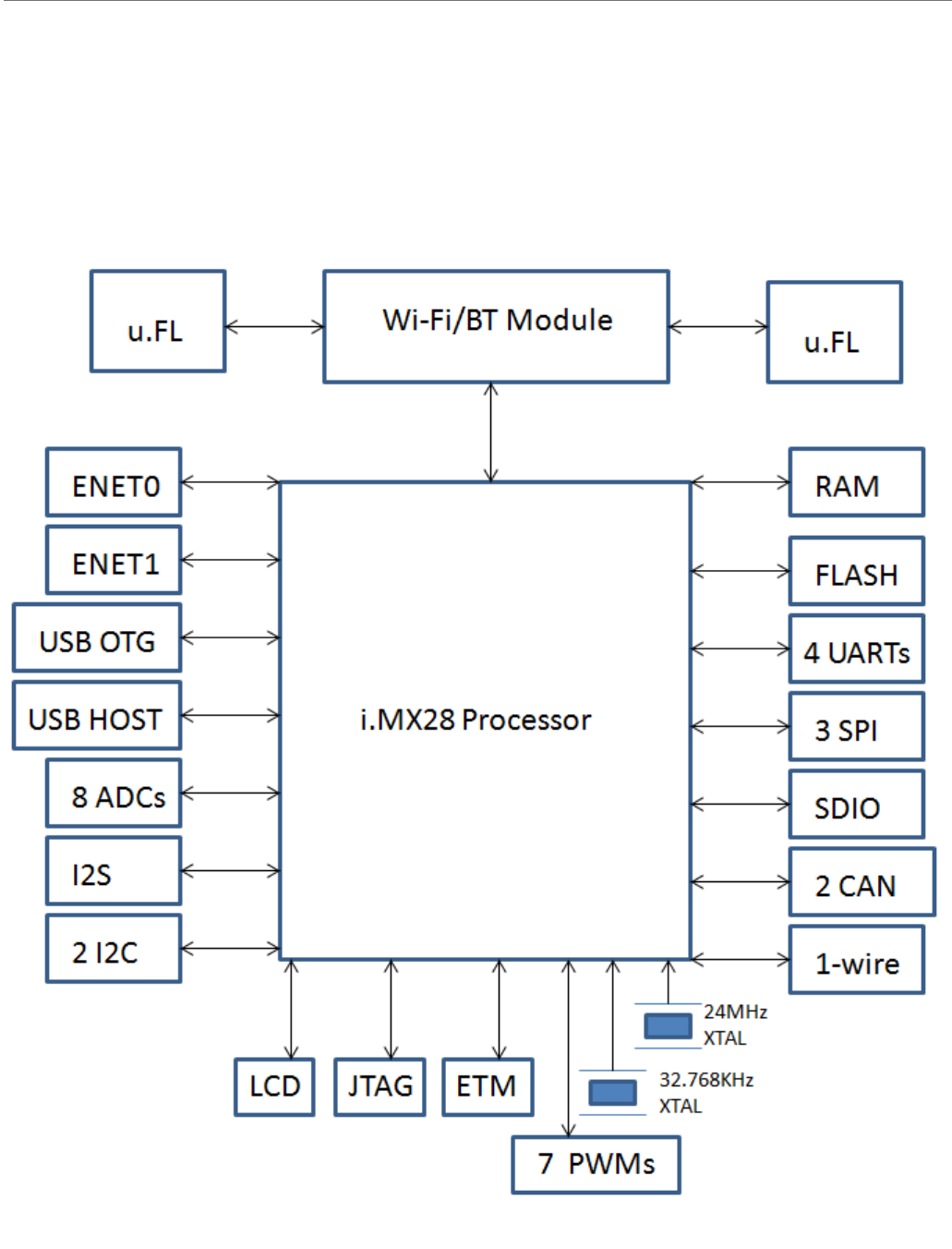
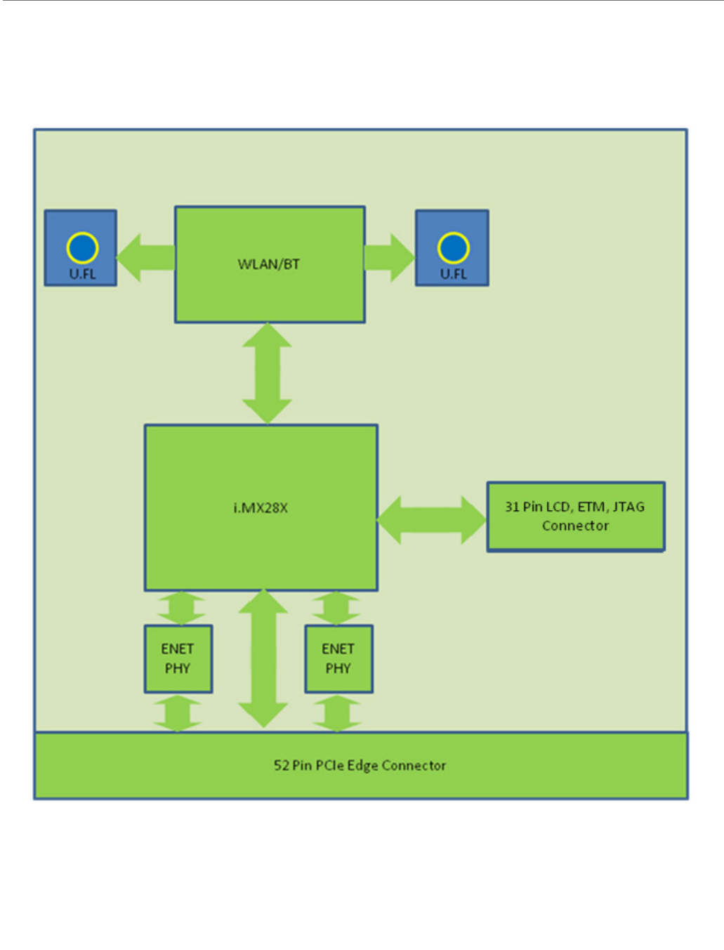
Block Diagram
The following figures show the block diagram of the Freescale i.MX285 CPU and the block
diagram of the ConnectCore for i.MX28 module.
CPU - Freescale i.MX28X
ConnectCore™ for i.MX28™ Hardware Reference
© 2013 Digi International, Inc. 11
ConnectCard for i.MX28
ConnectCore™ for i.MX28™ Hardware Reference
© 2013 Digi International, Inc. 12
Module Pinout
The module has 2 connectors. The 52 pin PCIe edge connector, and the 31 pin LCD connector.
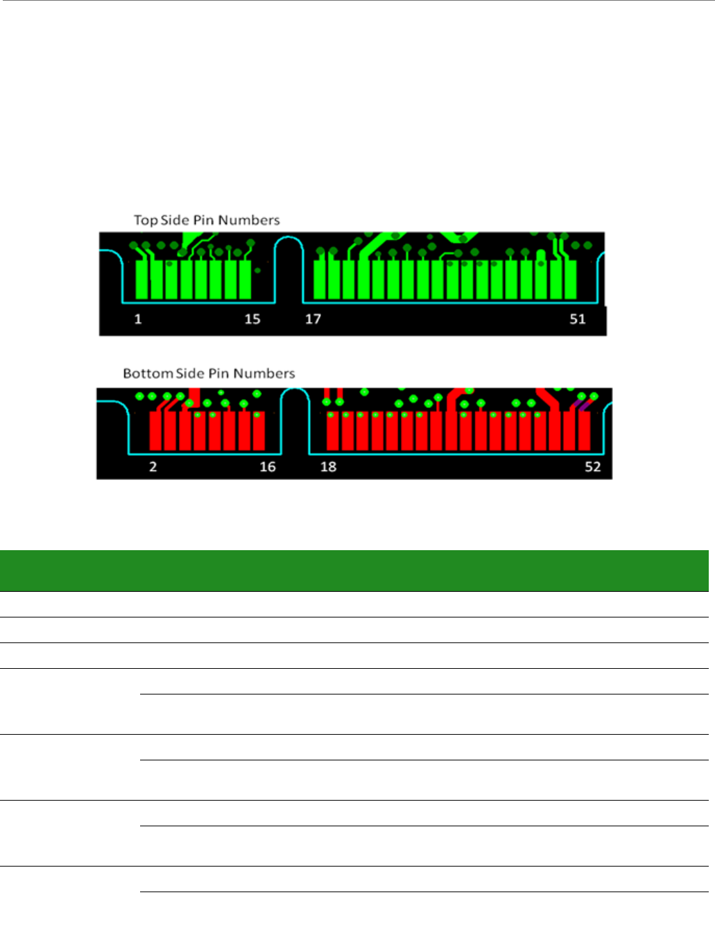
52-Pin PCle Edge Connector
The top side of the module has the shield on it and the bottom side of the module has the
i.MX28X on it. Pin numbering is shown below:
Pinout
Pin Pin Name Avail. on
i.MX287
Avail. on
i.MX280
Mux 0 Mux 1 Mux 2 Mux 3
1ENET0_TX+ X X
3ENET0_TX- X X
5GND X X
7AUART4_CTS X X SAIF0_MCLK PWM_3 AUART4_CTS GPIO3_20
XSSP3_SS0 AUART4_CTS ENET1_1588_EVENT1
_IN
GPIO3_27
9AUART4_RTS X X SAIF0_LRCLK PWM4 AUART4_RST GPIO3_21
XSSP3_MOSI AUART4_RX ENET1_1588_EVENT0
_IN
GPIO3_25
11 AUART4_RX X X SAIF0_BITCLK PWM_5 AUART4_RX GPIO3_22
XSSP3_MISO AUART4_RTS ENET1_1588_EVENT1
_OUT
GPIO3_26
13 AUART4_TX X X SAIF0_SDAT0 PWM_6 AUART4_TX GPIO3_23
XSSP3_SCK AUART4_TX ENET1_1588_EVENT0
_OUT
GPIO3_24

ConnectCore™ for i.MX28™ Hardware Reference
© 2013 Digi International, Inc. 13
15 Pswitch X X
GAP
17 USB0_DM X X
19 USB0_DP X X
21 USB0_ID X X PWM_2 USB0_ID USB1
_OVERCURRENT
GPIO3_18
23 Battery X X
25 HSADC0 X X HSADC0
27 CAN0_RX XGPMI_READY3 CAN0_RX HSADC_TRIGGER GPIO0_23
29 CAN0_TX XGPMI_READY2 CAN0_TX ENET0_TX_ER GPIO0_22
31 SSP1_SS XSSP1_SS SSP2_D7 ENET0_1588_EVENT3
_IN
GPIO2_15
X X LRADC0
33 SSP1_MOSI XSSP1_MOSI SSP2_D2 ENET0_1588_EVENT2
_IN
GPIO2_13
X X LRADC1
35 SSP1_MISO XSSP1_MISO SSP2_D6 ENET0_1588_EVENT3
_OUT
GPIO2_14
X X LRADC2
37 SSP1_SCK XSSP1_SCK SSP2_D1 ENET0_1588_EVENT2
_OUT
GPIO2_12
X X LRADC3
39 AUART1_CTS XAUART1_CTS USB0
_OVERCURRENT
TIMROT_ROTARYA GPIO3_6
X X LRADC4
41 AUART1_RTS XAUART1_RTS USB0_ID TIMROT_ROTARYA GPIO3_7
X X LRADC5
43 AUART1_TX X X AUART1_TX SSP3_CARD
_DETECT
PWM1 GPIO3_5
45 AUART1_RX X X AUART1_RX SSP2_CARD
_DETECT
PWM0 GPIO3_4
47 GND X X
49 ENET1_TX+ X
51 ENET1_TX- X
2ENET0_RX+ X X
Pin Pin Name Avail. on
i.MX287
Avail. on
i.MX280
Mux 0 Mux 1 Mux 2 Mux 3

ConnectCore™ for i.MX28™ Hardware Reference
© 2013 Digi International, Inc. 14
4ENET0_RX- X X
6VDD_5V X X
8I2C1_SCL X X PWM0 I2C1_SCL DUART_RX GPIO3_17
10 I2C1_SDA X X PWM1 I2C1_SDA DUART_TX GPIO3_16
12 DUART_RX X X I2C0_SCL TIMROT_ROTARYA DUART_RX GPIO3_24
14 DUART_TX X X I2C0_SDA TIMROT_ROTARYB DUART_TX GPIO3_25
16 RESET X X
GAP
18 SSP0_CMD X X SSP0_CMD GPIO2_8
20 SSP0_DATA0 X X SSP0_DATA0 GPIO2_0
22 SSP0_DATA1 X X SSP0_DATA1 GPIO2_1
XAUART3_CTS CAN1_TX ENET0_1588_EVENT1
_OUT
GPIO3_14
24 SSP0_DATA2 X X SSP0_DATA2 GPIO2_2
XAUART3_RTS CAN1_RX ENET0_1588_EVENT1
_IN
GPIO3_15
26 SSP0_DATA3 X X SSP0_DATA3 GPIO2_3
28 SSP0_SCLK X X SSP0_SCK GPIO2_10
30 SSP0_CARD
_DETECT
X X SSP0_CARD
_DETECT
GPIO2_9
32 LRADC6 /
SAIF1_DATA0
X X LRADC6
X X LCD_VSYNC SAIF1_DATA0 GPIO_1_28
34 i.MX28 3.3V
Output
X X
36 AUART2_CTS XAUART2_CTS I2C1_SCL SAIF1_BITCLK GPIO3_10
One-Wire X X
38 AUART2_RTS XAUART2_RTS I2C1_SDA SAIF1_LRCLK GPIO3_11
40 AUART2_RX XAUART2_RX SSP2_D2 SSP3_D5 GPIO3_8
42 AUART2_TX XAUART2_TX SSP3_D1 SSP3_D4 GPIO3_9
44 CAN1_RX XGPMI_CE3N CAN1_RX SAIF1_MCLK GPIO0_19
XAUART3_RX CAN0_TX ENET0_1588_EVENT0
_OUT
GPIO3_13
Pin Pin Name Avail. on
i.MX287
Avail. on
i.MX280
Mux 0 Mux 1 Mux 2 Mux 3

ConnectCore™ for i.MX28™ Hardware Reference
© 2013 Digi International, Inc. 15
Available Features
Standard variants are available with either the i.MX280 or i.MX287. Not all features are available on
all variants. For custom variants see your Digi International sales person.
Available Features - i.MX280 and i.MX287
46 CAN1_TX XGPMI_CE2N CAN1_TX ENET0_RX_ER GPIO0_18
XAUART3_TX CAN0_RX ENET0_1588_EVENT0
_IN
GPIO3_12
48 VDD_5V X X
50 ENET1_RX+ X
USB1_DM XUSB1_DM
52 ENET1_RX- X
USB1_DP XUSB1_DP
Function i.MX280 i.MX287
LCD Interface -Yes
Touch Screen -Yes
Ethernet x1 x2
L2 Switch -Yes
CAN -x2
12-bit ADC x8 x8
High-speed ADC x1 x1
USB 2.0 OTG HS with HS
PHY x1
OTG HS with HS
PHY x1
HS Host with HS
PHY x1
HS Host with HS
PHY x1
SDIO x4 x4
SPI x4 x4
Application UART x6 x5
Debug UART x1 x1
PWM -x8
S/PDIF Tx -Yes
Security Yes Yes
Pin Pin Name Avail. on
i.MX287
Avail. on
i.MX280
Mux 0 Mux 1 Mux 2 Mux 3

ConnectCore™ for i.MX28™ Hardware Reference
© 2013 Digi International, Inc. 16
Thermal Considerations
Heat dissipation of the i.MX28 processor is highly dependent on the selected clock speed and
the peripherals it is supporting. Freescale specifies the maximum allowed junction
temperature of the processor to be limited to 105C, which translates to the following
processor case temperatures:
The ConnectCard for i.MX28 has been built to function up to 65C at full clock speed without a
thermal pad attached (not included in the development kit) between the processor and the
development board, and has been checked up to 75C with the thermal pad attached. There is
a large ground area left open under the module on the development board under the module
to accommodate the thermal pad. Bergquist makes thermal pad material in various
thicknesses. The CCi.MX28 has been characterized using a combination of 2500S20 and
2000S40 pads from Bergquist.
Designs using the ConnectCard for i.MX28 need to ensure that the rating maximums above are
not exceeded in the application. Case temperature can be measured using an external probe
on the center of the i.MX28 processor package, and the junction temperature can be
monitored in software through an on-die temperature sensor provided in the i.MX processor.
Because of the limitation above, active and/or passive thermal management may be required
(thermal pad, airflow, clocking, etc.) like the Bergquist 2500s20 and 2000S40 thermal pads.
For more information on thermal consideration with the i.MX28 processor see the Freescale
i.MX28 data sheet.
31 Pin LCD, JTAG, and ETM Connector
The module uses a 31 pin ZIF connector for the LCD, JTAG and ETM connections. These pins
can also be used for GPIO functions. A list of possible connectors is shown below, the list is
not all inclusive:
The standard connection is 18 bit color, and the CC-WMX-PF58-TK-JT comes with this option.
Processor Speed Max Ambient Temperature w/o
Thermal Pad
Max Case Temperature
454 MHz 59 C 84 C
360 MHz 68 C 88 C
261 MHz 69 C 88 C
64 MHz 99 C 102 C
Manufacturer Part Number
FCI SFV31R-1STE1HLF
FCI SFV31R-1STE1LF
TYCO ELECTRONICS 3-1734839-1

ConnectCore™ for i.MX28™ Hardware Reference
© 2013 Digi International, Inc. 17
Standard 18 Bit Color Pinout
Pin Pin Name i.MX28 Mux 0 Mux 1 Mux 2 Mux 3
1LCD_DOTCLK N1 LCD_DOTCLK SAIF1_MCLK ETM_TCLK GPIO1_30
2LCD_VSYNC M6 LCD_RESET LCD_VSYNC LCD_RESET /
LCD_VSYNC
GPIO3_31
3LCD_HSYNC M1 LCD_HSYNC SAIF1_SDATA1 EMT_TCTL GPIO1_29
4LCD_ENABLE N5 LCD_ENABLE LCD_ENABLE GPIO1_25
5LCD_WR_RWN /
ETM_TCLK
K1 LCD_WR_RWN LCD_HSYNC ETM_TCLK GPIO1_32
6LCD_D17 R3 LCD_D17 ETM_DA6 GPIO1_17
7LCD_D16 T3 LCD_D16 ETM_DA16 GPIO1_16
8LCD_D15 / ETM_DA15 U3 LCD_D15 ETM_DA15 GPIO1_15
9LCD_D14 / ETM_DA14 U2 LCD_D14 ETM_DA14 GPIO1_14
10 LCD_D13 / ETM_DA13 T2 LCD_D13 ETM_DA13 GPIO1_13
11 LCD_D12 / ETM_DA12 T1 LCD_D12 ETM_DA12 GPIO1_12
12 LCD_D11 / ETM_DA11 R2 LCD_D11 ETM_DA11 GPIO1_11
13 LCD_D10 / ETM_DA10 R1 LCD_D10 ETM_DA10 GPIO1_10
14 LCD_D09 / ETM_DA9 P3 LCD_D09 ETM_DA4 ETM_DA9 GPIO1_0
15 LCD_D08 / ETM_DA8 P2 LCD_D08 ETM_DA3 ETM_DA8 GPIO1_8
16 LCD_D07 / ETM_DA7 P1 LCD_D07 ETM_DA7 GPIO1_7
17 LCD_D06 / ETM_DA6 N2 LCD_D06 ETM_DA6 GPIO1-6
18 LCD_D05 / ETM_DA5 M3 LCD_D05 ETM_DA5 GPIO1_5
19 LCD_D04 / ETM_DA4 M2 LCD_D04 ETM_DA9 ETM_DA4 GPIO1_4
20 LCD_D03 / ETM_DA3 L3 LCD_D03 ETM_DA8 ETM_DA3 GPIO1_3
21 LCD_D02 / ETM_DA2 L2 LCD_D02 ETM_DA2 GPIO1_2
22 LCD_D01 / ETM_DA1 K3 LCD_D01 ETM_DA1 GPIO1_1
23 LCD_D00 / ETM_DA0 K2 LCD_D00 ETM_DA0 GPIO1_0
24 ETM_TCTL P4 LCD_RD_E LCD_VSYNC ETM_TCTL GPIO1_24
25 LCD_CS /
Touch_Interrupt
P5 LCD_CS GPIO1_27
26 JTAG_TRST# D14 JTAG_RTCK
27 JTAG_TMS D12
28 JTAG_TDO E13
29 JTAG_TDI E12

ConnectCore™ for i.MX28™ Hardware Reference
© 2013 Digi International, Inc. 18
Provisions have been made on the module for 24 bit color without the JTAG connections.
24 bit Color Pinout (without JTAG)
30 JTAG_TCK E11
31 JTAG_RTCK E14
Pin Pin Name i.MX28
Pin
Mux 0 Mux 1 Mux 2
1LCD_DOTCLK N1 LCD_DOTCLK SAIF1_MCLK ETM_TCLK
2LCD_VSYNC M6 LCD_RESET LCD_VSYNC
3LCD_HSYNC M1 LCD_HSYNC SAIF1_SDATA1 EMT_TCTL
4LCD_ENABLE N5 LCD_ENABLE
5LCD_WR_RWN /
ETM_TCLK
K1 LCD_WR_RWN LCD_HSYNC ETM_TCLK
6LCD_D17 R3 LCD_D17 ETM_DA6
7LCD_D16 T3 LCD_D16 ETM_DA7
8LCD_D15 / ETM_DA15 U3 LCD_D15 ETM_DA15
9LCD_D14 / ETM_DA14 U2 LCD_D14 ETM_DA14
10 LCD_D13 / ETM_DA13 T2 LCD_D13 ETM_DA13
11 LCD_D12 / ETM_DA12 T1 LCD_D12 ETM_DA12
12 LCD_D11 / ETM_DA11 R2 LCD_D11 ETM_DA11
13 LCD_D10 / ETM_DA10 R1 LCD_D10 ETM_DA10
14 LCD_D09 / ETM_DA9 P3 LCD_D09 ETM_DA4 ETM_DA9
15 LCD_D08 / ETM_DA8 P2 LCD_D08 ETM_DA3 ETM_DA8
16 LCD_D07 / ETM_DA7 P1 LCD_D07 ETM_DA7
17 LCD_D06 / ETM_DA6 N2 LCD_D06 ETM_DA6
18 LCD_D05 / ETM_DA5 M3 LCD_D05 ETM_DA5
19 LCD_D04 / ETM_DA4 M2 LCD_D04 ETM_DA9 ETM_DA4
20 LCD_D03 / ETM_DA3 L3 LCD_D03 ETM_DA8 ETM_DA3
21 LCD_D02 / ETM_DA2 L2 LCD_D02 ETM_DA2
22 LCD_D01 / ETM_DA1 K3 LCD_D01 ETM_DA1
23 LCD_D00 / ETM_DA0 K2 LCD_D00 ETM_DA0
24 ETM_TCTL P4 LCD_RD_E LCD_VSYNC ETM_TCTL
Pin Pin Name i.MX28 Mux 0 Mux 1 Mux 2 Mux 3

ConnectCore™ for i.MX28™ Hardware Reference
© 2013 Digi International, Inc. 19
Module Operation
Not all functions are available at the same time or on all module variants. The configuration
of the resources will depend on the system requirements, and some planning may be
required to set up the available interfaces in a particular application.
DC Power
The ConnectCard for i.MX28 has 5V and Battery inputs:
The 5V supply will have a maximum of 5.25V and a minimum operating voltage of 4.75V. This
supply is assumed to come from a regulated supply with about 1A of current capability. The
development board supply can generate up to 1.5A.
The Battery voltage needs to be between 3.4 and 4.242V. If both 5V and Battery supplies are
connected the module will automatically use the 5V supply.
In addition, there is a +3.3V line coming out of the module which can be used to power
external circuitry. This supply can be disabled in low power mode so that it can be used as a
low power configuration signal.
Thermal Considerations
At high clock rates the i.MX28 will pull more current. The ConnectCard for i.MX28 has been
built to function up to 65C at full clock speed with a thermal pad attached (not included in
the development kit) between the processor and the development board. There is a large
ground area left open under the module on the development board under the module to
accommodate the thermal pad. Bergquist makes thermal pad material in various
thicknesses. The CCi.MX28 has been characterized using a combination of 2500S20 and
2000S40 pads from Bergquist. Consult the Freescale data sheet for the i.MX28 for thermal
requirements.
System Boot
The ConnectCard for i.MX28 boot process begins at Power On Reset when the hardware reset
logic forces the ARM core to begin execution starting from the on-chip boot ROM. Boot ROM
25 LCD_CS /
Touch_Interrupt
P5 LCD_CS LCD_ENABLE
26 LCD_D18 U4 LCD_D18 ETM_DA18
27 LCD_D19 T4 LCD_D19 ETM_DA19
28 LCD_D20 R4 LCD_D20 ENET1_1588_EVENT2_OUT ETM_DA3
29 LCD_D21 U5 LCD_D21 ENET1_1588_EVENT2_IN ETM_DA2
30 LCD_D22 T5 LCD_D22 ENET1_1588_EVENT3_OUT ETM_DA1
31 LCD_D23 R5 LCD_D23 ENET1_1588_EVENT3_IN ETM_DA0
Pin Pin Name i.MX28
Pin
Mux 0 Mux 1 Mux 2

ConnectCore™ for i.MX28™ Hardware Reference
© 2013 Digi International, Inc. 20
code uses the state of the internal register BOOT_MODE[1:0] as well as the state of various
eFUSEs and/or GPIO settings to determine the boot flow behavior of the module.
The following Boot modes are supported:
Boot from FLASH
Boot from SD Card
Boot from USB
Boot from JTAG
Each mode is selected by applying the proper bit pattern to LCD_D00, LCD_D01, LCD_D02,
LCD_D03, and LCD_D04. The default boot mode is FLASH. No internal eFUSEs have been set.
For more information on boot modes, please refer to chapter 12 of the Freescale
documentation.
Audio System
The audio system is using an SAIF interface configured as I2S.
LCD System
The LCD is available through a 31 pin ZIF connector on the top side of the module (see
variants for availability). The development kit uses a cable from NICOMATIC (part number
050P331K0076-406406 ). The default LCD setting is for 18 bit color, and the development
board is set up for this setting as well. A special 24 bit color option is available (not
supported in current variant list) but will disconnect the JTAG functionality. Touch screen
functionality is supported by connecting LRADC2-5. There are multiple SPI ports available to
communicate with a SPI touch screen controller (the development board uses SSP1).
PWM0,1,3,4,5 and 6 are available to use for backlight control (the development board uses
PWM0).
GPIO
In general any of the modules digital pins can be set as a GPIO. There are 3 available states
for any GPIO-- low, high , and high impedance. Each of the GPIO pins is capable of
functioning on either at 1.8 or 3.3V as well as an interrupt/trigger pin. Each individual GPIO
can be dynamically programmed at any time to be in either: High-impedance (for input,
three-state, or open-drain applications); Low; High; or Controlled by one of the three
selectable i.MX28 peripheral module interfaces. The state of any GPIO pin can be read at
any time regardless of its configuration. Analog pins may not be set as GPIO. The following
functions cannot be used for GPIO functions:
Ethernet
USB
LRADC (although muxed functions can be used)
HSADC
One Wire (Technically it could be by controlling the I2C line)
JTAG

ConnectCore™ for i.MX28™ Hardware Reference
© 2013 Digi International, Inc. 21
PSWITCH
RESET
DC connections (5V, Battery, and GND)
Interfaces
1-Wire
The ConnectCard for i.MX28 provides a 1-wire interface to communicate with 1-wire devices
such as EEPROMs, secure memory and sensors. The required protocol for accessing the
generic 1-wire device is defined by Maxim. The Maxim DS2482-100 interface is used for 1-
Wire communication. The 1-wire interface uses a strong 3.3V pull-up.
ADCs and Touch Screen
The ConnectCard for i.MX28 provides both Low-Resolution ADC's (LRADC) and a High speed
ADC (HSADC). In either case, the ADC's have 12 bit resolution and an absolute accuracy of
1.3%.
LRADC's can operate with up to 3.3V inputs, with an absolute accuracy of 1.3%. In addition to
ADC functions, LRADC 2-6 can also be used for touch screen control (2-5 are used on the
development board for touch screen control). There are 16 ADC channels available, the
channel assignments are shown in the table below:
ADC Channel Number Assignment
0-6 LRADC0-6 measure the voltage on the seven application-dependant LRADC
pins.
LRADC2-6 can be used for 4/5-wire touch screen control.
LRADC6 can be used for a wiper of 5-wire touch screen controller and external
temperature sensing, but they cannot be enabled at the same time in hardware
configuration.
7Dedicated to measuring the battery voltage.
8, 9 Dedicated to measuring the internal die temperature.
10 Dedicated to measuring the internal 3.3V rail, and for calibrating the voltage
levels measured on the auxiliary channels.
11 Reserved input for analog testing.
12 Dedicated to measuring the internal 1.8V rail.
13 Dedicated to measuring the internal 1.5V rail.
14 Dedicated to measuring the band gap reference voltage and can be used to
calibrate out a portion of the LRADC measurement error. In most cases the band
gap reference error dominates the total LRADC error, and this calibration is not
helpful.
15 Dedicated to measuring the 5V supply to detect possible issues with the 5V rail
dropping.

ConnectCore™ for i.MX28™ Hardware Reference
© 2013 Digi International, Inc. 22
The HSADC is capable of measuring up to 2Msps, and can be used in conjunction with the
PWM's to generate signals for external devices like a linear image scanner sensor. The HSADC
can be triggered to start the conversion of an analog source in three modes:
Trigger by Software
Trigger signal generated by the PWM block
Trigger by an input pin from an external source
CAN
The ConnectCard for i.MX28 includes two FlexCAN2 controllers which are compatible with
the CAN 2.0B protocol specification. The CAN Protocol Interface (CPI) manages the serial
communication on the CAN bus, requesting RAM access for receiving and transmitting
message frames, validating received messages and performing error handling. The Message
Buffer Management (MBM) handles Message Buffer selection for reception and transmission,
taking care of arbitration and ID matching algorithms. The CAN bus can operate up to 1Mbps
The FlexCAN2 controllers require additional hardware, an example of this circuitry can be
found on the development board.
Ethernet
The ConnectCard for i.MX28 provides up to two 10/100 Mbps Ethernet connections (see
variants table for number of Ethernet connections). The MAC and PHY are on the module,
and the Magnetics and Jack need to be provided external to the module. The connections
from the module are differential pairs for the TX and RX ports. In variants with 1 Ethernet 2
USB ports are provided.
USB
The ConnectCard for i.MX28 includes up to two high-speed Universal Serial Bus (USB) version
2.0 controllers and integrated USB Transceiver Macrocell Interface (UTMI) PHYs. The i.MX28
device interface can be attached to USB 2.0 hosts and hubs running in the USB 2.0 high-speed
mode at 480 Mbps. It can be attached to USB 2.0 full-speed interfaces at 12 Mbps. Note that
a dual-device configuration is not supported. The USB controllers and integrated PHYs
support high-speed Host modes for peer-to-peer file interchange. The USB controller can also
be configured as a high-speed host.
Each USB is a dynamically configured port that can support up to seven RX and seven TX
endpoints besides EP0, each of which may be configured for bulk, interrupt, or isochronous
transfers.
USB0 is a high speed, OTG-capable universal serial bus. The ConnectCard for i.MX28 can
operate as a host controller that can support eight endpoints: one control, one bulk-out, one
bulk-in, and five flexible endpoints. Further, it can negotiate with another OTG system to be
either the host or the device in a peer connection.
Note that USB1 is a host-only USB port.
Variants with two USB ports have only one Ethernet port, as noted in the Ethernet section
above.

ConnectCore™ for i.MX28™ Hardware Reference
© 2013 Digi International, Inc. 23
I2C
The ConnectCard for i.MX28 contains 2 two-wire SMB/I2C bus interfaces. Each interface can
act as a slave or a master on the SMB. The I2C interfaces are multiplexed with the DUART,
and I2C0 is used for the DUART on the development board, and no termination resistors are
on the module for this interface. I2C1 is used to run the 1-wire interface, and 2.2K ohm
termination resistors are located on the module. The supply voltage of these resistors is
3.3V.
The I2C bus is a standard two-wire serial interface for connecting the ConnectCard for i.MX28
to peripheral devices or host controllers. The I2C buss operates at a standard speed of up to
100Kbps and a fast speed of up to 400Kbps. The ConnectCard for i.MX28 can act as either
master of slave on the I2C bus. This module is also capable of supporting multi-master
configurations. The device address of the 1-wire bridge is 00, and cannot be used by other
I2C devices connected to the I2C1 bus.
SAIF (Audio)
The ConnectCard for i.MX28 includes a Serial Audio Interface (SAIF) configured as an I2S
intervace. It is capable of transmitting and receiving in 16 or 24 bit audio, by connecting to
an audio codec. A possible example circuit is shown in the development board schematics.
AUARTs and DUART
Up to four application UARTs (AUART), and 1 debug (console) DUART are available on the
ConnectCard for i.MX28 module. The AUARTs are capable of running up to 3.25 Mbps, while
the DUART is capable of speeds up to 115Kbps. Variants using the i.MX287 include flow
control on all application UARTs.
Through the DUART the CPU reads and writes data and control/status information through
the APBX interface. The DUART does the serial to parallel conversions on data received from
a peripheral device and the parallel to serial conversion on data transmitted to the
peripheral device. The buffer size for the DUART is 32 bytes. Flow control is not included for
the debug UART.
Pulse Width Modulator (PWM)
The ConnectCard for i.MX28 module provides access to PWM0 through PWM6. The PWMs can
be used in place of GPIO pins to control such things as LED Brightness, HSADC, and LCD
backlight control. Independent output control of each phase allows 0, 1, or high-impedance
to be independently selected for the active and inactive phases. Individual outputs can be
run in lock step with guaranteed non-overlapping portions for differential drive applications.
Synchronous Serial Ports (SPI, and SD)
The three available Synchronous Serial Ports on the ConnectCard for i.MX28 module can
support SPI master and Slave modes up to 52MHz speeds. In addition SSP0 is capable of SD
card functions including booting.
Real Time Clock (RTC)
The real-time clock (RTC) and alarm share a one-second pulse time domain. The watchdog
reset and millisecond counter run on a one-millisecond time domain. The RTC, alarm, and

ConnectCore™ for i.MX28™ Hardware Reference
© 2013 Digi International, Inc. 24
persistent bits use persistent storage and reside in a special power domain (crystal domain)
that remains powered up even when the rest of the chip is in its powered-down state.
The ConnectCard for i.MX28 development board does not include a backup battery, so the
RTC will not be maintained through power cycles.
Liquid Crystal Display (LCD)
Some versions of the ConnectCard for i.MX28 includes an LCD connector that is separate from
the edge connector. Smart LCDs are available in a range of sizes and capabilities, from simple
text-only displays to WVGA, 16/18/24 bpp color TFT panels. This device supports displays
that support moving pictures and require the RGB interface mode (called DOTCLK interface
in this document).
Wi-Fi and Bluetooth
The ConnectCard for i.MX28 is available with an Qualcom-Atheros 802.11 a b g n and BT4.0
interfaces. Wi-Fi data rates up to 150 Mbps (5GHz n-mode) are possible. For variants
without BT a diversity antenna (using the 2 u.FL ports) is utilized for the 2.4GHz band. For
variants with BT a single u.FL antenna connection for both bands is used.
The module is built with coexistence in mind and handles the BT coexistence internally.
Cellular coexistence filtering is onboard to aid in designing systems susceptible to cellular
interference.
A mini access point mode is available in the Wi-Fi with up to 5 clients. This mode is limited
to non DFS channels. The channels available are shown below:
US and Canada - 2.4 GHz band, 5.8, 5.15-5.25 GHz only
EU - 2.4 GHz band only
Japan - 2.4 GHz band only
Embedded Trace Macrocell
The ConnectCard for i.MX28 includes a stand-alone ARM CoreSight Embedded Trace
Macrocell, ETM9CSSingle, which provides a instruction trace and a data trace for the ARM9
microprocessor. This function is available on the same connector as the LCD, and many of
the pins are shared with the LCD controller. This feature is disabled by default. To enable
Embedded Trace Macrocell, external hardware is needed to set LCD_D05 to high during reset
(rever to the i.MX28 boot mode configuration).
Reset
The reset pin on the module is low asserted. A low pulse will reset the module. There is an
internal pull up resistor to 3.3V, so no external pull up resistor is needed.
Recovery and Power
The power pin is used to turn the ConnectCard for i.MX28 module on when only the battery
supply is connected. This is done by connecting about 1V to the pin for 100ms.
The power pin is also used to place the module in recovery mode. This is done by placing
3.3V on the pin for more than 5 seconds. The sb_loader can then be used to boot the part
through the USB OTG (USB0) interface.

ConnectCore for i.MX53
© 2013 Digi International, Inc.. 25
NAND FLASH
The ConnectCard for i.MX28 module includes either 128MB or 256MB of NAND FLASH from the
Micron Technologies MT29F series. These chips operate from 1.8V.
DDR2 RAM
The DDR2 RAM on the ConnectCard for i.MX28 module is either 128MB or 256MB from the
Micron Technologies MT47 series.
© 2013 Digi International, Inc. 26
About the Development Board
CHAPTER 2
The Development Board for the ConnectCardTfor i.MX28 is set up to allow testing of the
interfaces on the module. These various interfaces are selected by switches, and not all
interfaces are available at the same time.
In addition to the switches there are jumpers, pushbutton switches, potentiometers,
various header connectors, and various connectors to handle the interfaces. All the
required circuitry for the interfaces is included on the development board.
What’s on the Development Board?
Locking barrel power supply port for 12V wall adapter
Power switch
Connectors for Digi 802.3af Power Over Ethernet module (sold separately)
5V regulated power supply
4.2V regulated power supply (battery simulator)
3.3V Regulated power supply to run the dev board and XBee modules
Screw Terminal blocks for 5V, 4.2V external supplies
2 X Ethernet connections
2 X UART 232 SUB-D 9-pin connectors
1 X DUART 232 SUB-D 9-pin Connector
2 X UART with TTL levels
2 X CAN bus with termination resistors selection and SUB-D 9-pin connections
1 X USB OTG connector
1 X USB Host connector
1 X micro SD card holder
HSADC header
LRADC header and potentiometers
SPI and I2C headers
One Wire header and EEPROM

ConnectCore™ for i.MX28™ Hardware Reference
© 2013 Digi International, Inc. 27
Audio Interface
18 Bit Color LCD interface
Boot mode selection jumpers
ETM header
JTAG header
XBee Through-Hole and SMT sockets
User Buttons and LEDs
Power and Reset buttons
GPIO header
3 X u.FL to RPSMA connectors (2 for the CCi.MX28 module and 1 for XBee antennas)
ConnectCore™ for i.MX28™ Hardware Reference
© 2013 Digi International, Inc. 28
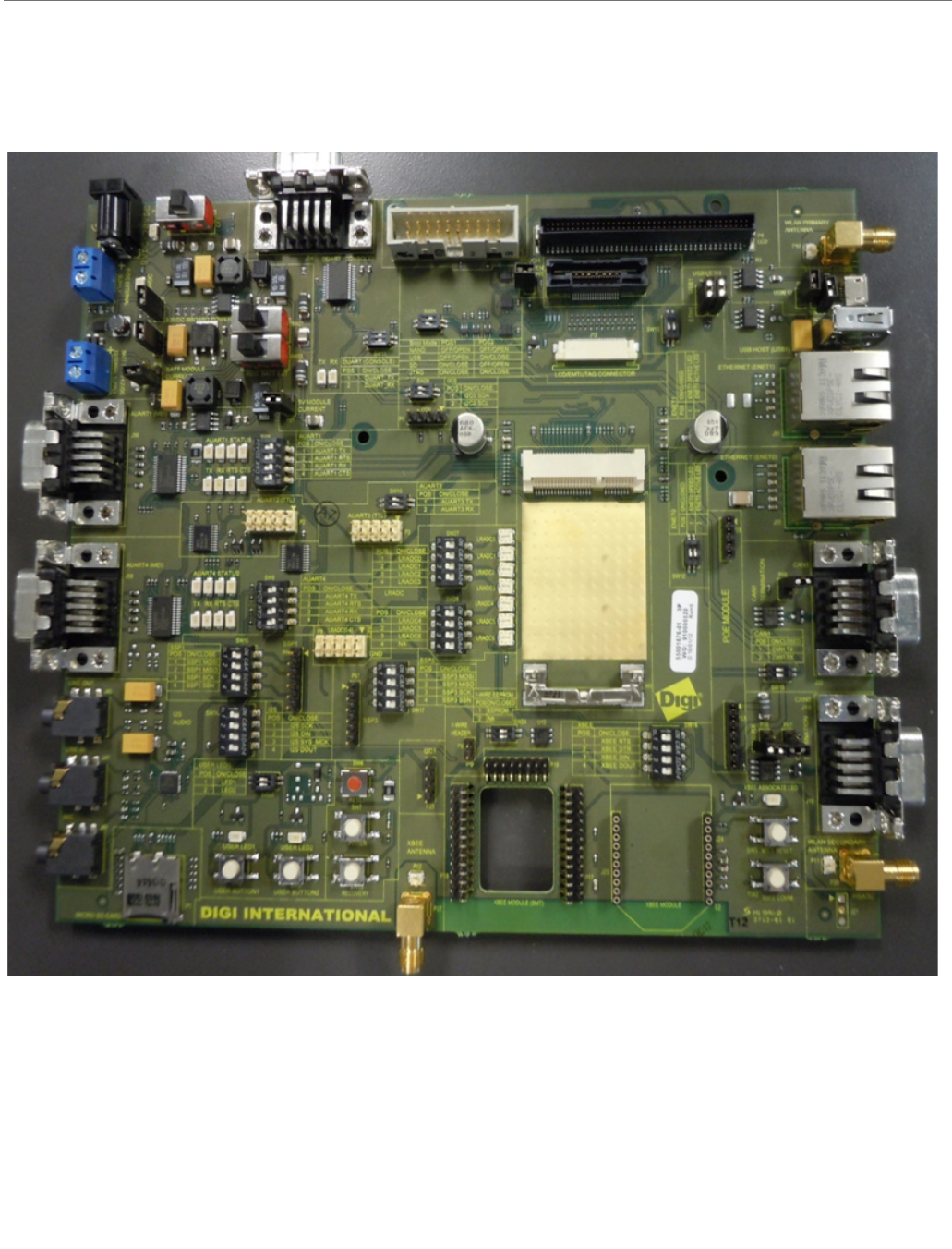
The Development Board
Since some interfaces share a common pin on the ConnectCard for i.MX28 module, and may
be used for multiple interfaces on the development board, conflicts between interfaces are
possible. Tables are included to show which interfaces share resources. Tables in this
section show the position of switches and jumpers. For switches ON/CLOSE indicates the
switch is set to the on position connecting the two sides of the switch, conversely OFF/OPEN
indicates the switch is in the off position disconnecting the two sides of the switch. For
Jumpers SHORT indicates the jumper is installed across the two posts, and OPEN indicates
the jumper is not installed. The functions are shown in rows. To set up a function follow the

ConnectCore™ for i.MX28™ Hardware Reference
© 2013 Digi International, Inc. 29
instructions on the row for that function. If the table has nothing in the box, there is no
conflict with that switch or jumper.
Header Pin Outs
The pin out for the interface headers are shown below.
SSP1 (P85) & SSP3 (P87)
PIN FUNCTION
1 VCC_3V3
2MOSI
3MISO
4SCK
5SSN
6GND
LRADC (0-6) (P8) AUART2 (P2) AUART3 (P3)
PIN FUNCTION PIN FUNCTION PIN FUNCTION
1 LRADC0 1 NC 1 NC
2 LRADC1 2 NC 2 NC
3 LRADC2 3 RX 3 RX
4 LRADC3 4 NC 4 NC
5 LRADC4 5 TX 5 TX
6 LRADC5 6 NC 6 NC
7 LRADC6 7 NC 7 NC
8NC 8 NC 8 NC
9GND 9GND 9GND
10 3.3VDC 10 3.3VDC 10 3.3VDC
JTAG (P34) ETM (J4)
PIN FUNCTION PIN FUNCTION PIN FUNCTION
1 3.3VDC 1 NC 2 NC
2 3.3VDC 3 NC 4 NC
3 TRST 5 GND 6 TCLK

ConnectCore™ for i.MX28™ Hardware Reference
© 2013 Digi International, Inc. 30
4 GND 7 DBGRQ 8 DBGACK
5 TDI 9 NC 10 EXTTRIG
6 GND 11 NC 12 VTREF
7 TMS 13 NC 14 VSUPPLY
8 GND 15 NC 16 DA7
9 TCK 17 NC 18 DA6
10 GND 19 NC 20 DA5
11 RTCK 21 NC 22 DA4
12 GND 23 DA15 24 DA3
13TD0 25DA1426 DA2
14 GND 27 DA13 28 DA1
15 RESET 29 DA12 30 GND
16 GND 31 DA11 32 GND
17 NC 33 DA10 34 VTREF
18 GND 35 DA9 36 TCTL
19 Pull Down 37 DA8 38 DA0
20 GND 39 GND 40 GND
41 GND 42 GND
43 GND
LCD (P4)
PIN FUNCTION PIN FUNCTION
1D162D17
3D124D13
5D146D15
7D168D17
9NC10NC
11 NC 12 NC
13 GND 14 GND
15 D10 16 D11
17 D06 18 D07
19 D08 20 D09
JTAG (P34) ETM (J4)

ConnectCore™ for i.MX28™ Hardware Reference
© 2013 Digi International, Inc. 31
21 D10 22 D11
23 NC 24 NC
25 NC 26 NC
27 GND 28 GND
29 D04 30 D05
31 D00 32 D01
33 D02 34 D03
35 D04 36 D05
37 NC 38 NC
39 NC 40 NC
41 GND 42 GND
43 ENABLE 44 DOTCLK
45 PWM0 46 GND
47 VSYNC 48 HSYNC
49 NC 50 NC
51 NC 52 NC
53 NC 54 NC
55 GND 56 GND
57 SSP1_MOSI 58 SSP1_SCK
59 AUART1_CTS 60 AUART1_RTS
61 I2C1_SDA 62 I2C1_SCL
63 SSP1_SSN 64 SSP1_SCK
65 SSP1_MOSI 66 SSP1_MISO
67 NC 68 Touch Jumper
69 NC 70 NC
71 TOUCH_INTERRUPT 72 GND
73 3.3VDC 74 3.3VDC
75 WALL_12V 76 WALL_12V
77 WALL_12V 78 WALL_12V
79 NC 80 NC
LCD (P4)

ConnectCore™ for i.MX28™ Hardware Reference
© 2013 Digi International, Inc. 32
Development Board Set Up
Power Supplies
The development board includes two 5V, one 4.2V, and one 3.3V regulators. One 5V regulator
is set up to power the module from the 9VDC to 30VDC wall adaptor, the other 5V regulator is
a buck boost regulator to power the USBs. The 4.2V regulator is set up to power the module
through the BATT port. The 3.3V regulator powers both the development board and the XBee
if so equipped. The development board has an ON/OFF switch, SW1. The power switch SW1
can switch both 9V-30VDC input power supply and 12VDC coming out of the optional PoE
module (Digi P/N DG-ACC-POE). However, if a power plug is present on the DC power jack,
PoE is disabled.
The 5V and BATT module supplies can also come from an external jack. For the 5V external
jack the voltage range is 4.75DC to 5.25VCD. For the external BATT supply the allowable
range is 3.4VDC to 4.2VDC. The module will not auto boot from the BATT supply, but will
from the 5V supply. If operating form only the BATT supply the POWER BUTTON will need to
be pressed to turn the module on.
The 3.3V board supply and XBee supply along with the 5V USB supply are powered from either
the 5V or BATT module supplies, with the 5V supply being the primary and the BATT supply
being the secondary supply.
The module can be connected to both the 5V and BATT supply at the same time. When
connected to both supplies the module will draw its power form the 5V supply, as will the
board, USB, and XBee.
ConnectCore™ for i.MX28™ Hardware Reference
© 2013 Digi International, Inc. 33
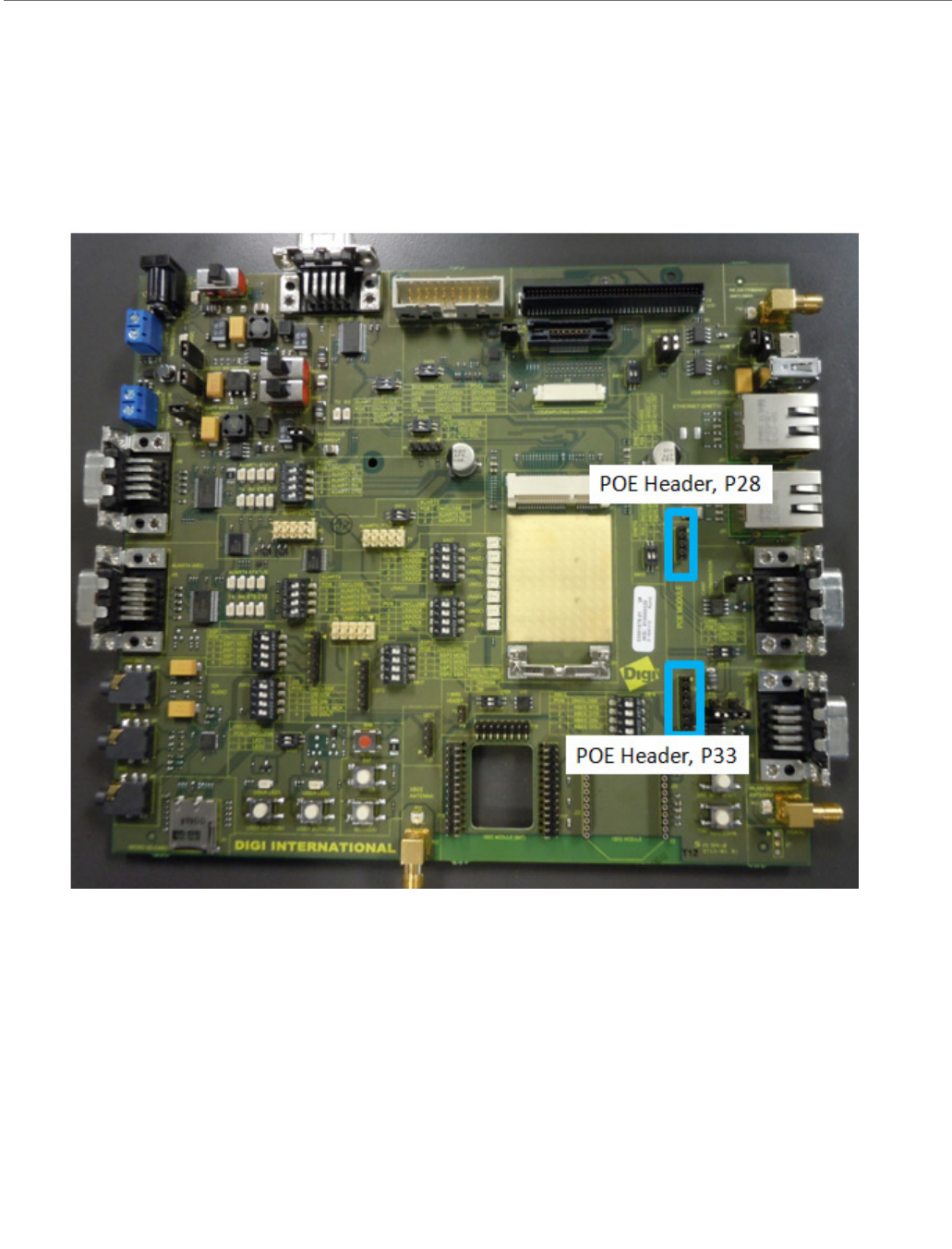
Power over Ethernet (PoE) - IEEE802.3af
PoE is only available through ENET0 on the development board.
If the wall plug is connected Poe is disabled.
The development board provides two PoE module connectors, P28 and P33, to plug a Digi PoE
module (DG-ACC-POE). The PoE module is an optional accessory item that can be plugged on
the development board through the two connectors.
• P28, input connector: provides access to the PoE signals from the Ethernet
connector
• P33, output connector: provides the output power supply from the PoE module
ConnectCore™ for i.MX28™ Hardware Reference
© 2013 Digi International, Inc. 34
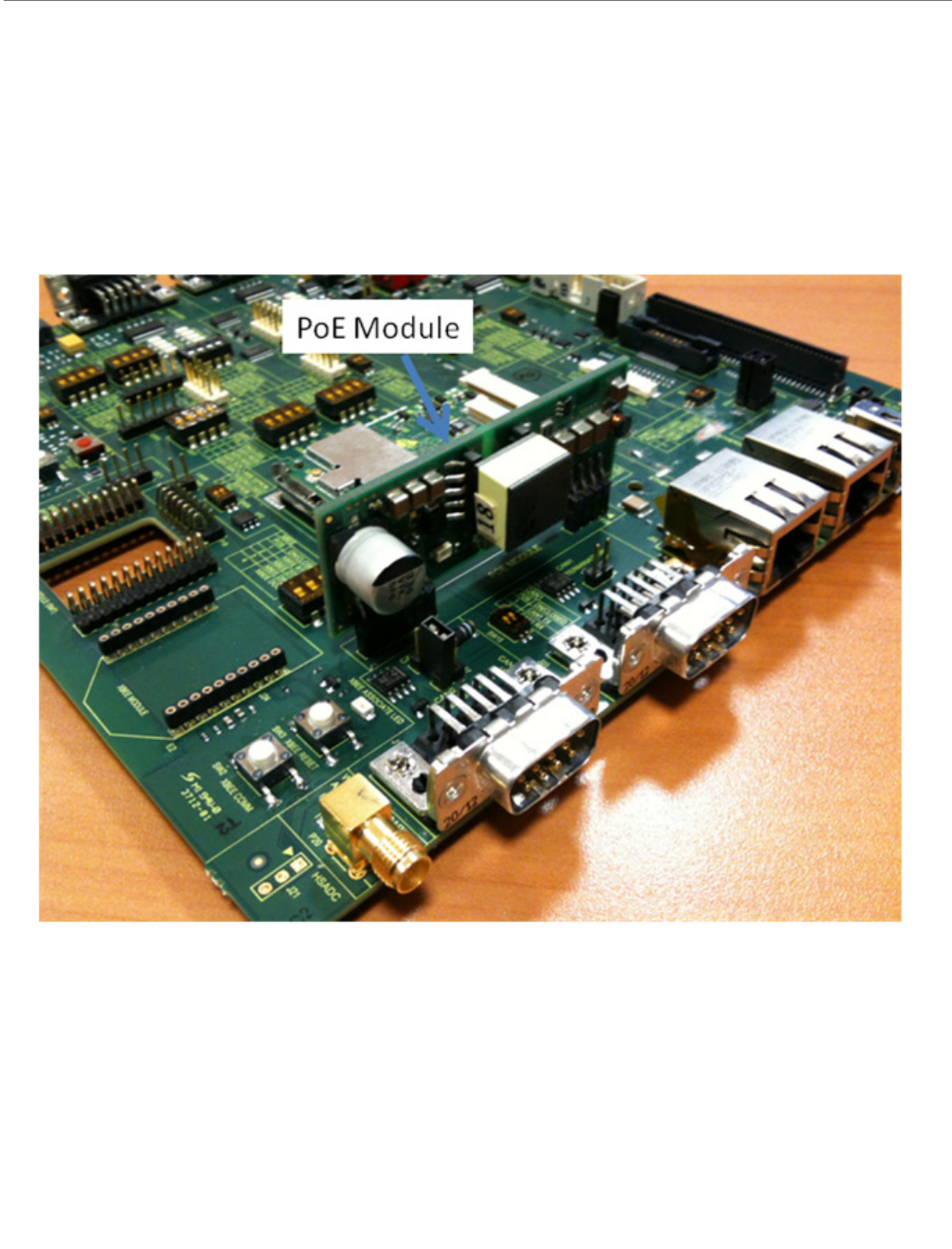
The PoE Module
Plug in the PoE module at a right angle to the development board, as shown in the picture
below.
Note: the PoE module is part of the optional Digi 802.3af application kit (sold separately, Digi
P/N DG-ACC-POE).

ConnectCore™ for i.MX28™ Hardware Reference
© 2013 Digi International, Inc. 35
PoE Connector (power in), P28
The table below provides the pinout of the PoE input connector:
PoE Connector (power out), P33
The table below provides the pinout of the PoE output connector:
Pin Signal
1Poe_TX_CT
2 Poe_RX_CT
3 Poe_RJ45_4/5
4 Poe_RJ45_7/8
Pin Signal
1 +12V_PoE
2 +12V_PoE
3GND
4GND
5 Poe_GND
6 Poe_GND
ConnectCore™ for i.MX28™ Hardware Reference
© 2013 Digi International, Inc. 36
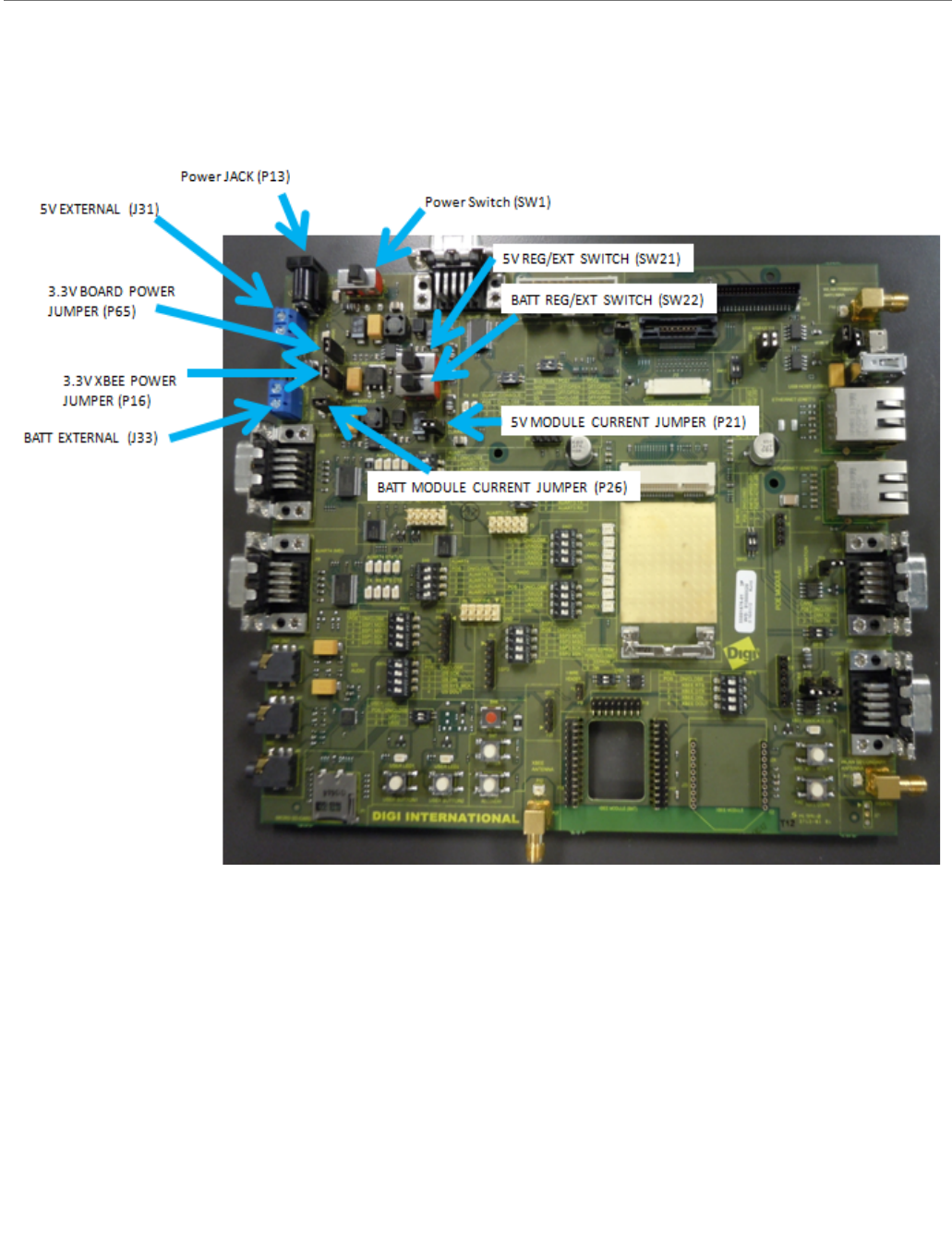
Connector, Switch, and Jumper Locations

ConnectCore™ for i.MX28™ Hardware Reference
© 2013 Digi International, Inc. 37
Power Functions and Settings
9-30VDC, P13 set
4.2V and 5V External Terminal Blocks, P13 Open
5V and BATT supplies can be connected at the same time, however 5V will be selected by the
CCi.MX28 in this case.
The term REG refers to connection to the onboard regulator, and the term EXT refers to
connection to an external supply using the screw terminals. To use the internal regulator
function move the switch (SW21 or SW22) to the REG setting, and the opposite setting (EXT)
to connect the module to an external supply.
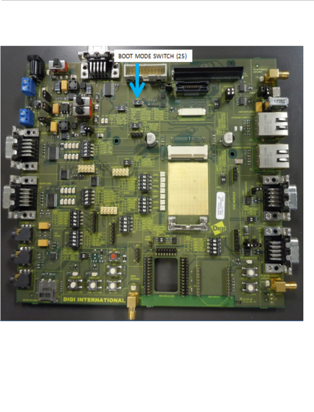
Boot Mode
The Boot Mode of the ConnectCard for i.MX28 is set using SW25. Setting the boot mode
requires the 31 connector FFC cable, as five of the LCD lines are used to set the boot mode.
On board logic sets up the boot mode in accordance with the Freescale requirements.
Some LCDs can drive these lines to undesired states. The development board includes
circuitry to prevent the LCD from corrupting the boot mode.
If your final design does not include the video cable, you may still boot from USB using the
recovery button. This is explained in Chapter 3.
Function J31 J33 SW1 SW21 SW22 P65 P16 P26 P21
5V Regulator,
no XBee
NC NC ON REG EXT SHORT OPEN OPEN SHORT
5VRegulator,
with XBee
NC NC ON REG EXT SHORT SHORT OPEN SHORT
Battery
Regulator, no
XBee
NC NC ON EXT REG SHORT OPEN SHORT OPEN
Battery
Regulator, with
XBee
NC NC ON EXT REG SHORT SHORT SHORT OPEN
Function J31 J33 SW1 SW21 SW22 P65 P16 P26 P21
External 5V, no
XBee
4.75-
5.25VDC
NC OFF EXT EXT SHORT OPEN OPEN SHORT
External 5V,
with XBee
4.75-
5.25VDC
NC OFF EXT EXT SHORT SHORT OPEN SHORT
External Battery
no XBee
NC 3.4-4.2VDC ON EXT EXT SHORT OPEN SHORT OPEN
External Battery
with XBee
NC 3.4-4.2VDC ON EXT EXT SHORT SHORT SHORT OPEN
ConnectCore™ for i.MX28™ Hardware Reference
© 2013 Digi International, Inc. 38
Switch Location

ConnectCore™ for i.MX28™ Hardware Reference
© 2013 Digi International, Inc. 39
Function and Settings
Development Board Button Functions
The development board has seven buttons with different functions.
XBEE RESET BUTTON and XBEE COMM BUTTON
These two buttons are for an XBee module. For the XBee button function, consult the XBee
manual.
USER BUTTON1 and USER BUTTON2
The two user buttons are connected to the ConnectCard for i.MX28 modules as GPIOs to
UART2_RTS (module pin 38) and SD_CARDDETECT (module pin 30). User Buttons provide a
high (3.3V) level until pressed, then a low (GND) level is sent.
CCi.MX28 RESET BUTTON
This button resets the module and is red in color. Pressing this button will cause the module
to reboot.
CCi.MX28 POWER BUTTON
This button is used to turn the module on when it is operating from the BATT power supply.
The module will not auto-boot from the battery supply, but will from the 5V supply.
CCi.MX28 RECOVERY BUTTON
This button is used to put the module in recovery mode. In this mode, the SB_LOADER
program can be used to boot the module through the USB OTG (USB0) port.
Boot Mode SW25 P1 SW25 P2
NAND FLASH OFF/OPEN OFF/OPEN
USB OFF/OPEN ON/CLOSE
SD ON/CLOSE OFF/OPEN
JTAG ON/CLOSE ON/CLOSE
ConnectCore™ for i.MX28™ Hardware Reference
© 2013 Digi International, Inc. 40
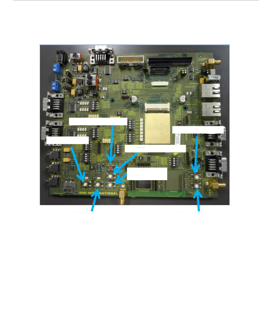
Button Locations
USER BUTTON1 (SW4)
CCIMX28 RESET BUTTON (SW6)
CCIMX28 POWER BUTTON (SW7)
XBEE RESET BUTTON (SW3)
CCIMX28 RECOVERY
BUTTON (SW23)
USER BUTTON2 (SW5) XBEE COMM BUTTON (SW3)
ConnectCore™ for i.MX28™ Hardware Reference
© 2013 Digi International, Inc. 41
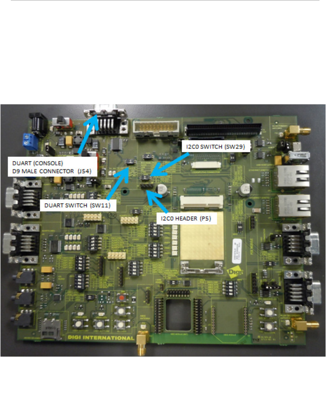
DUART (Console) and I2C0
The normal mode of sending commands and receiving information from the module about
those commands is through the DUART. The DUART is multiplexed with I2C0, and switches
are provided to select the function desired.
The DUART status can be seen in the DUART LEDs located close to SW11.
Connector and Switch Locations

ConnectCore™ for i.MX28™ Hardware Reference
© 2013 Digi International, Inc. 42
Functions and Settings
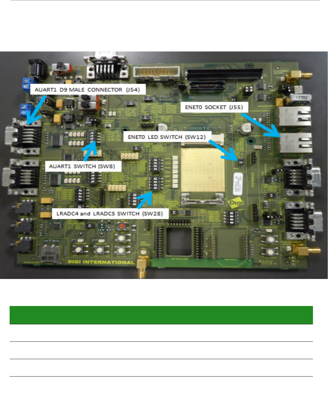
AUART1, ENET0, LRADC4, LRADC5, and User LEDs
AUART1
AUART1 can be operated with or without flow control, and each of the functions are
connected separately to the D9 connector through switch SW8. The status of AUART 1 can be
seen in the AUART1 LEDs located next to SW8.
ENET0
ETHERNET (ENET0) is wired directly to the module and no switching is required. The LEDs for
ENET0 are operated by GPIOs and are available through switch SW12.
LRADC4 & LRADC5
LRADC4 and LRADC5 are connected to separate potentiometers through switch SW28 and
SW20. When not using the potentiometer, it is best to leave the switch in the OFF/OPEN
condition to avoid having the potentiometer voltage affecting the other signals on the line.
All the LRADCs (0-6) are also available through the LRADC header.
User LEDs
USER_LED1 and USER_LED2 are connected to PWM1, and PWM0 respectively. The LEDs will
turn on with a low and off with a high.
Function SW11 P1 SW11 P2 SW29 P1 SW29 P2
DUART_TX ON/CLOSE ON/CLOSE OFF/OPEN OFF/OPEN
DUART_RX ON/CLOSE ON/CLOSE OFF/OPEN OFF/OPEN
I2C0_SDA OFF/OPEN OFF/OPEN ON/CLOSE ON/CLOSE
I1C0_SCL OFF/OPEN OFF/OPEN ON/CLOSE ON/CLOSE
ConnectCore™ for i.MX28™ Hardware Reference
© 2013 Digi International, Inc. 43
Connector and Switch Locations
Function and Settings
Function SW8
P1
SW8
P2
SW8
P3
SW8
P4
SW12
P1
SW12
P2
SW20
P1
SW20
P2
SW28
P1
SW28
P2
AUART1_TX ON/
CLOSE
OFF/
OPEN
AUART1_RTS ON/
CLOSE
OFF/
OPEN
OFF/
OPEN
AUART1_RX ON/
CLOSE
OFF/
OPEN
AUART1_CTS ON/
CLOSE
OFF/
OPEN
OFF/
OPEN

ConnectCore™ for i.MX28™ Hardware Reference
© 2013 Digi International, Inc. 44
ENET0_SPEED_LED OFF/
OPEN
ON/
CLOSE
OFF/
OPEN
ENET0_ACTIVE_LED OFF/
OPEN
ON/
CLOSE
OFF/
OPEN
LRADC4 POT OFF/
OPEN
OFF/
OPEN
ON/
CLOSE
LRADC5 POT OFF/
OPEN
OFF/
OPEN
ON/
CLOSE
USER_LED1 OFF/
OPEN
ON/
CLOSE
USER_LED2 OFF/
OPEN
ON/
CLOSE
Function SW8
P1
SW8
P2
SW8
P3
SW8
P4
SW12
P1
SW12
P2
SW20
P1
SW20
P2
SW28
P1
SW28
P2

ConnectCore™ for i.MX28™ Hardware Reference
© 2013 Digi International, Inc. 45
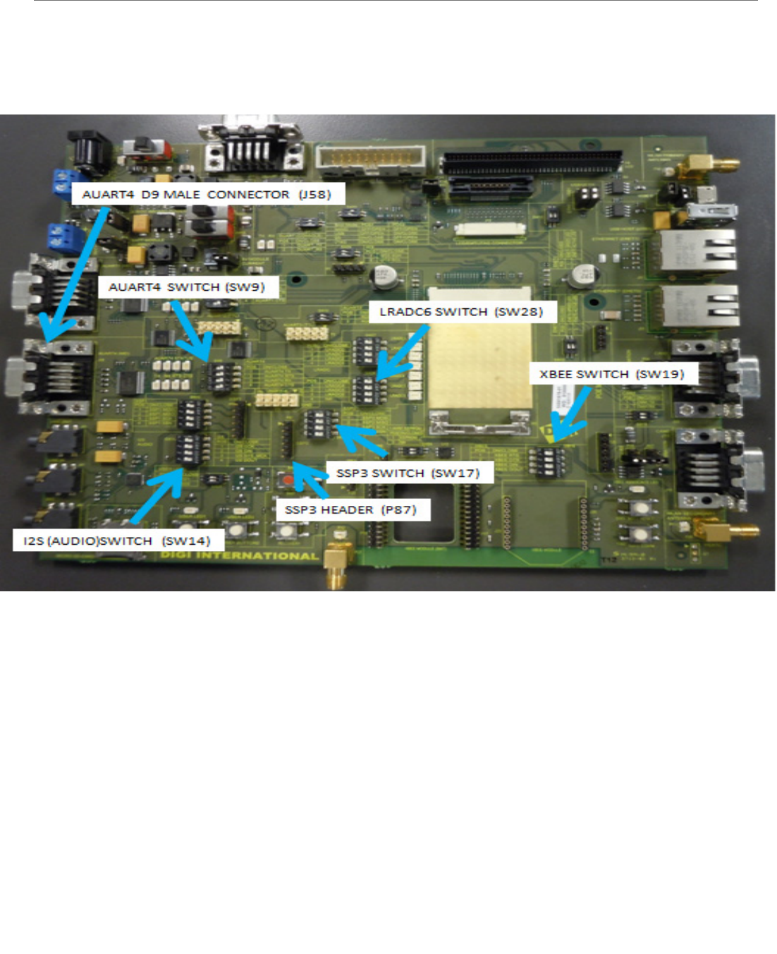
AUART4, SSP3, I2S (Audio), LRADC6, and XBee
AUART4
AUART4 can be operated with or without the flow control, and each of the functions are
connected separately to the D9 connector through switch SW9. The status of AUART4 can be
seen in the AUART4 LEDs located next to SW9.
SSP3
SSP3 is connected to its header (P87) through switch SW17.
I2S (Audio)
I2S (AUDIO) connections are made through switch SW14. The CODEC also uses I2C1. The
LRCLK is multiplexed with AUART4_CTS.
LRADC6
LRADC6 is connected to its potentiometer through switch SW28 POS3. When not using the
potentiometer, it is best to leave the switch in the OFF/OPEN condition to avoid having the
potentiometer voltage affecting the other signals on the line. All the LRADCs (0-6) are also
available through the LRADC header.
XBee
XBee connections are made through switch SW19. AUART4 is used to communicate with the
XBee module.
ConnectCore™ for i.MX28™ Hardware Reference
© 2013 Digi International, Inc. 46
Connector and Switch Locations

ConnectCore™ for i.MX28™ Hardware Reference
© 2013 Digi International, Inc. 47
Function and Settings Table - AUART4
Function and Settings Table - SSP3
Function AUART4_TX AUART4_RTS AUART4_RX AUART4_CTS
SW9 / P1 ON/CLOSE
SW9 / P2 ON/CLOSE
SW9 / P3 ON/CLOSE
SW9 / P4
SW14 / P1
SW14 / P2 OFF/OPEN
SW17 / P1 OFF/OPEN
SW17 / P2 OFF/OPEN
SW17 / P3 OFF/OPEN
SW17 / P4 OFF/OPEN
SW19 / P1 OFF/OPEN
SW19 / P2 OFF/OPEN
SW19 / P3 OFF/OPEN
SW19 / P4 OFF/OPEN
SW28 / P3
Function SSP3_MOSI SSP3_MISO SSP3_SCK SSP3_SS0
SW9 / P1 OFF/OPEN
SW9 / P2 OFF/OPEN
SW9 / P3 OFF/OPEN
SW9 / P4 OFF/OPEN
SW14 / P1
SW14 / P2 OFF/OPEN
SW17 / P1 ON/CLOSE
SW17 / P2 ON/CLOSE
SW17 / P3 ON/CLOSE
SW17 / P4 ON/CLOSE
SW19 / P1 OFF/OPEN
SW19 / P2 OFF/OPEN
SW19 / P3 OFF/OPEN

ConnectCore™ for i.MX28™ Hardware Reference
© 2013 Digi International, Inc. 48
Function and Settings Table - I2S
Note: I2S (Audio) also uses I2C1
SW19 / P4 OFF/OPEN
SW28 / P3
Function I2S_SAIF1_DATA0 I2S_SAIF0_MCLK I2S_SAIF0_DATA0 I2S_SAIF0_BITCLK
SW9 / P1 OFF/OPEN
SW9 / P2
SW9 / P3 OFF/OPEN
SW9 / P4 OFF/OPEN
SW14 / P1 ON/CLOSE
SW14 / P2 ON/CLOSE
SW17 / P1
SW17 / P2 OFF/OPEN
SW17 / P3 OFF/OPEN
SW17 / P4 OFF/OPEN
SW19 / P1 OFF/OPEN
SW19 / P2
SW19 / P3 OFF/OPEN
SW19 / P4 OFF/OPEN
SW28 / P3 OFF/OPEN
Function SSP3_MOSI SSP3_MISO SSP3_SCK SSP3_SS0

ConnectCore™ for i.MX28™ Hardware Reference
© 2013 Digi International, Inc. 49
Function and Settings Table - XBee
Function and Settings Table - LRADC6
Function XBEE_RTS XBEE_DTR XBEE DIN XBEE DOUT
SW9 / P1 OFF/OPEN
SW9 / P2 OFF/OPEN
SW9 / P3 OFF/OPEN
SW9 / P4 OFF/OPEN
SW14 / P1
SW14 / P2 OFF/OPEN
SW17 / P1 OFF/OPEN
SW17 / P2 OFF/OPEN
SW17 / P3 OFF/OPEN
SW17 / P4 OFF/OPEN
SW19 / P1 ON/CLOSE
SW19 / P2 ON/CLOSE
SW19 / P3 ON/CLOSE
SW19 / P4 ON/CLOSE
SW28 / P3
Function LRADC6
SW9 / P1
SW9 / P2
SW9 / P3
SW9 / P4
SW14 / P1 OFF/OPEN
SW14 / P2
SW17 / P1
SW17 / P2
SW17 / P3
SW17 / P4
SW19 / P1
SW19 / P2
SW19 / P3

ConnectCore™ for i.MX28™ Hardware Reference
© 2013 Digi International, Inc. 50
SW19 / P4
SW28 / P3 ON/CLOSE
Function LRADC6

ConnectCore™ for i.MX28™ Hardware Reference
© 2013 Digi International, Inc. 51
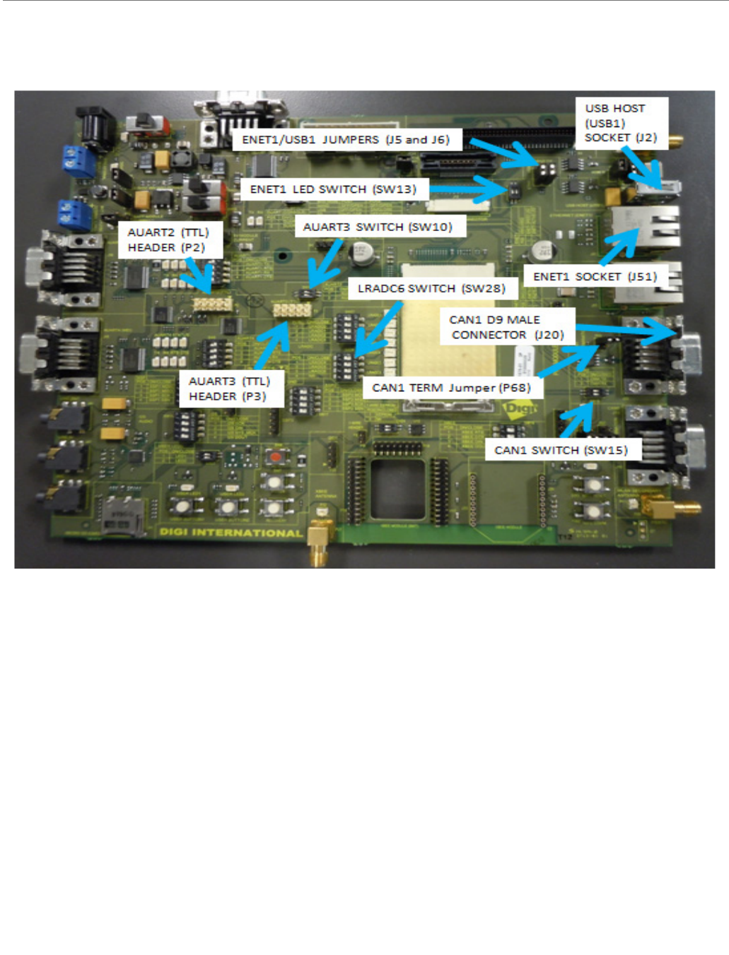
AUART2 (TTL), AUART3 (TTL), CAN1, ETHERNET (ENET1), and USB Host (USB1)
AUART2 (TTL)
This header needs no switches to operate. The flow control for AUART2 is not connected to
the header (P2).
AUART3
This header is connected to header P3 through switch SW10.
CAN1
The CAN1 header is connected to D9 Header J20 through Switch SW15. A termination resistor
is also available on the development board and is connected through jumper P68.
ETHERNET
The ETHERNET (ENET1) header is connected to the ENET socket J51, using jumpers J5 and J6.
The LEDs for ENET1 are available through GPIOs using SW13.
USB HOST (USB1)
For modules without ENET1, USB1 is available and is connected to the USB socket J2 using
jumpers J5 and J6.
ConnectCore for i.MX53
© 2013 Digi International, Inc.. 52
Connector, Switch, and Jumper Locations
Variants with ENET1 do not have USB1 and variants with USB1 do not have ENET1.

ConnectCore for i.MX53
© 2013 Digi International, Inc.. 53
Function and Settings Table - AUART3
Function and Settings Table - CAN1
Function and Settings Table - ENET1
Function AUART3_RX AUART3_TX
SW10 / P1 ON/CLOSE
SW10 / P2 ON/CLOSE
SW13 / P1 OFF/OPEN
SW13 / P2 OFF/OPEN
SW15 / P1 OFF/OPEN
SW15 / P2 OFF/OPEN
P68
J5 / ETH1
J5 / USB1
J6 / ETH1
J6 / USB1
Function CAN1_RX CAN1_TX CAN1_TERMINATION
SW10 / P1 OFF/OPEN
SW10 / P2 OFF/OPEN
SW13 / P1 OFF/OPEN
SW13 / P2 OFF/OPEN
SW15 / P1 ON/CLOSE
SW15 / P2 ON/CLOSE
P68 SHORT
J5 / ETH1
J5 / USB1
J6 / ETH1
J6 / USB1
Function ENET1_SPEED_LED ENET1_ACTIVE_LED ENET1_RX+ ENET1_RX-
SW10 / P1 OFF/OPEN
SW10 / P2 OFF/OPEN
SW13 / P1 ON/CLOSE

ConnectCore for i.MX53
© 2013 Digi International, Inc.. 54
Function and Settings Table - USB1
AUART2 has no switches to set. If the CAN1 Termination is not needed, P68 can be left OPEN.
SW13 / P2 ON/CLOSE
SW15 / P1 OFF/OPEN
SW15 / P2 OFF/OPEN
P68
J5 / ETH1 SHORT
J5 / USB1 OPEN
J6 / ETH1 SHORT
J6 / USB1 OPEN
Function USB1_DM USB1_DP
SW10 / P1
SW10 / P2
SW13 / P1
SW13 / P2
SW15 / P1
SW15 / P2
P68
J5 / ETH1 OPEN
J5 / USB1 SHORT
J6 / ETH1 OPEN
J6 / USB1 SHORT
Function ENET1_SPEED_LED ENET1_ACTIVE_LED ENET1_RX+ ENET1_RX-
ConnectCore for i.MX53
© 2013 Digi International, Inc.. 55
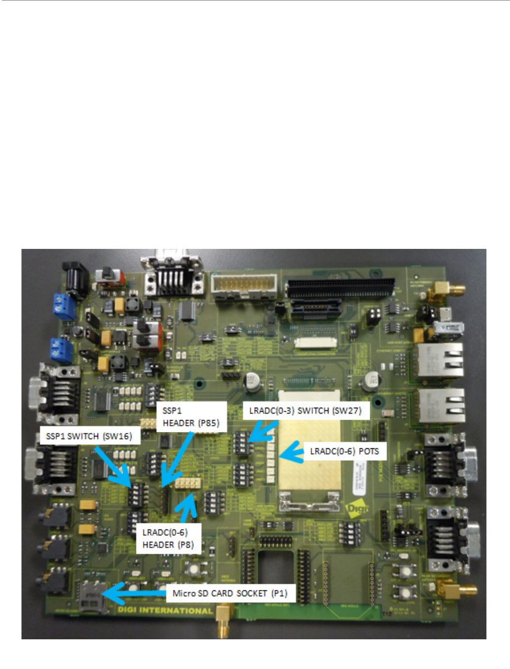
SD CARD, SSP1, LRADC0, LRADC1, LRADC2, and LRADC3
SD CARD
The SD CARD socket P1 requires not switches to operate.
SSP1
SSP1 or SPI1 is connected to header P85 through switch SW16.
LRADC0, LRADC1, LRADC2 and LRADC3
LRADC0, LRADC1, LRADC2 and LRADC3 are connected to their associated potentiometers
through switch SW27. These functions are also available on Header P8.
Connector, Switch, and Jumper Locations

ConnectCore for i.MX53
© 2013 Digi International, Inc.. 56
Function and Settings Table - SSP1
Function and Settings Table - LRADC0-3
Function SSP1_MOSI SSP1_MISO SSP1_SCK SSP1_SSN
SW16 / P1 ON/CLOSE
SW16 / P2 ON/CLOSE
SW16 / P3 ON/CLOSE
SW16 / P4 ON/CLOSE
SW27 / P1 OFF/OPEN
SW27 / P2 OFF/OPEN
SW27 / P3 OFF/OPEN
SW27 / P4 OFF/OPEN
Function LRADC0 POT LRADC1 POT LRADC2 POT LRADC3 POT
SW16 / P1
SW16 / P2 OFF/OPEN
SW16 / P3 OFF/OPEN
SW16 / P4 OFF/OPEN OFF/OPEN
SW27 / P1 ON/CLOSE
SW27 / P2 ON/CLOSE
SW27 / P3 ON/CLOSE
SW27 / P4 ON/CLOSE

ConnectCore for i.MX53
© 2013 Digi International, Inc.. 57
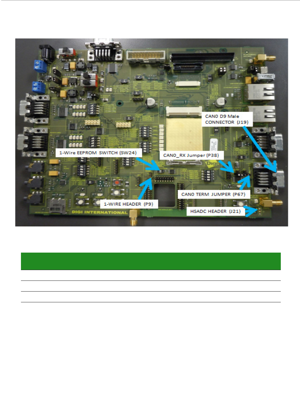
CAN0, HSADC, AND1-Wire
CAN0
CAN0_RX is connected to D9 header J19 through jumper P38. No switch is needed for
CAN0_TX. The termination resistor is available on jumper P67
HSADC
The HSADC header (J21) is not populated on the development board.
1-Wire
1-Wire requires no switch to operate. An onboard 1-Wire EEPROM is provided for testing.
The EEPROM is connected to the 1-Wire interface using SW24 pos 1.
ConnectCore for i.MX53
© 2013 Digi International, Inc.. 58
Connector, Switch, and Jumper Locations
Function and Settings Table
1-Wire Header has no switches
CAN0_TX has no switches
HSADC0 Header is not populated
SW24 P2 is not connected
Function 1-WIRE
EEPROM
CAN0_RX CAN0_TERMINATION HS
ADC_TRIGGER
SW24 / P1 ON/CLOSE
P38 ON/CLOSE OFF/OPEN
P67 ON/CLOSE
ConnectCore for i.MX53
© 2013 Digi International, Inc.. 59
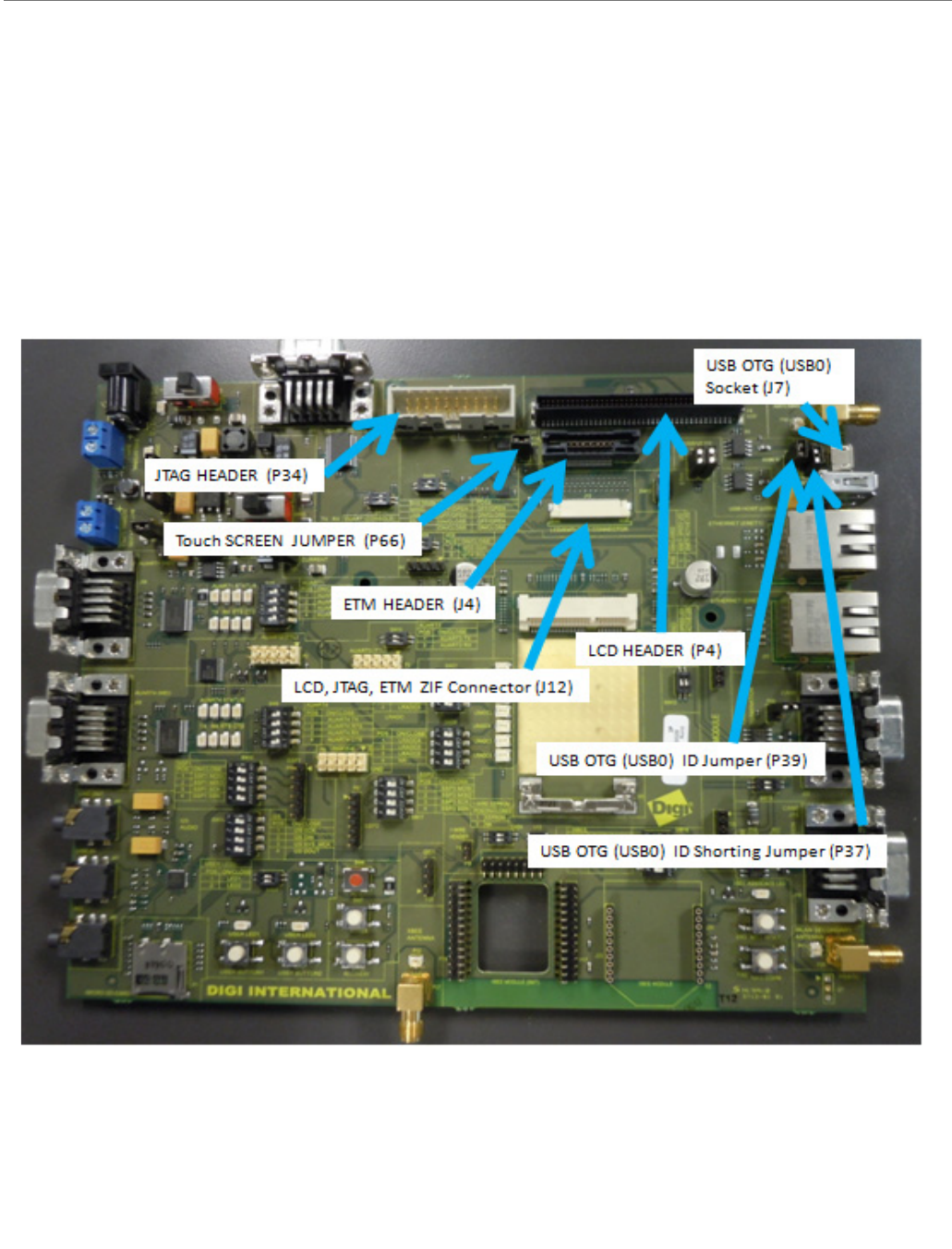
LCD, ETM, JTAG, USB OTG (USB0)
The locations of the LCD, ETM, JTAG and USB OTG (USB0) are shown below.
The USB OTG (USB0) can be operated with or without the OTG functionality. The USB0_ID
line is connected to the socket (J7) through jumper P39. A short to GND of the USB0_ID line
is available on jumper P37.
To operate the LCD, ETM and JTAG the 31 pin LCD cable must be connected from the
development board to the module.
Connector and Jumper Locations
Functions and Settings
LCD has no switches. To operate the touch screen OPEN P66.
JTAG has no switches
ETM has no switches

ConnectCore for i.MX53
© 2013 Digi International, Inc.. 60
LCD JTAG ETM ZIF connector is for the FFC 31 pin cable connecting these interfaces to the
CCi.MX28
© 2013 Digi International, Inc. 61
Certifications
CHAPTER 3
Agency Certifications
United States FCC
The ConnectCard™ for i.MX28 Module complies with Part 15 of the FCC rules and
regulations. Compliance with the labeling requirements, FCC notices and antenna usage
guidelines is required.
To fulfill FCC Certification, the OEM must comply with the following regulations:
The system integrator must ensure that the text on back side of the module is placed
on the outside of the final product.
ConnectCard™ for i.MX28 RF Module may only be used with antennas that have been
tested and approved for use with this module [refer to the antenna tables in this
section].
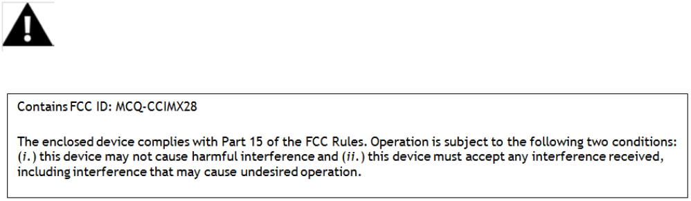
OEM Labeling Requirements
WARNING: The Original Equipment Manufacturer (OEM) must ensure that FCC labeling
requirements are met. This includes a clearly visible label on the outside of the final product
enclosure that displays the contents shown in the figure below.
Required FCC Label for OEM products containing the ConnectCard™ for i.MX28 RF Module:
FCC Notices
IMPORTANT: The ConnectCard™ for i.MX28 RF Module has been certified by the FCC for use
with other products without any further certification (as per FCC section 2.1091).
Modifications not expressly approved by Digi could void the user's authority to operate the
equipment.
IMPORTANT: OEMs must test final product to comply with unintentional radiators (FCC
section 15.107 & 15.109) before declaring compliance of their final product to Part 15 of
the FCC Rules.

ConnectCore™ for i.MX28™ Hardware Reference
© 2013 Digi International, Inc. 62
IMPORTANT: The ConnectCard™ for i.MX28 RF module has been certified for remote and base
radio applications. If the module will be used for portable applications, the device must
undergo SAR testing.
This equipment has been tested and found to comply with the limits for a Class B digital
device, pursuant to Part 15 of the FCC Rules. These limits are designed to provide reasonable
protection against harmful interference in a residential installation. This equipment
generates uses and can radiate radio frequency energy, and if not installed and used in
accordance with the instructions, may cause harmful interference to radio communications.
However, there is no guarantee that interference will not occur in a particular installation.
If this equipment does cause harmful interference to radio or television reception, which can
be determined by turning the equipment off and on, the user is encouraged to try to correct
the interference by one or more of the following measures: Re-orient or relocate the
receiving antenna, Increase the separation between the equipment and receiver, Connect
equipment and receiver to outlets on different circuits, or Consult the dealer or an
experienced radio/TV technician for help.
FCC-Approved Antennas
The ConnectCard™ for i.MX28 can be installed utilizing antennas and cables constructed with
non-standard connectors (RPSMA, RPTNC, etc.).
The modules are FCC approved for fixed base station and mobile applications for the
channels indicated in the tables below. If the antenna is mounted at least 20cm (8 in.) from
nearby persons, the application is considered a mobile application. Antennas not listed in the
table must be tested to comply with FCC Section 15.203 (Unique Antenna Connectors) and
Section 15.247 (Emissions).
ConnectCard™ for i.MX28: ConnectCard™ for i.MX28 RF Modules have been tested and
approved for use with all the antennas listed in the tables below. (Cable-loss is required
when using gain antennas as shown below.)
The antennas in the tables below have been approved for use with this module. Digi does not
carry all of these antenna variants. Contact Digi Sales for available antennas.
ConnectCore for i.MX28 Hardware Reference
© 2013 Digi International, Inc.. 63
Antennas Approved for Use with the ConnectCard™ for i.MX28 Wi-Fi Modules
Note: * If using the RF module in a portable application (for example - if the module is used in a handheld device and the antenna is less than
20cm from the human body when the device is in operation): The integrator is responsible for passing additional SAR (Specific
Absorption Rate) testing based on FCC rules 2.1091 and FCC Guidelines for Human Exposure to Radio Frequency Electromagnetic
Fields, OET Bulletin and Supplement C. The testing results will be submitted to the FCC for approval prior to selling the integrated
unit. The required SAR testing measures emissions from the module and how they affect the person.
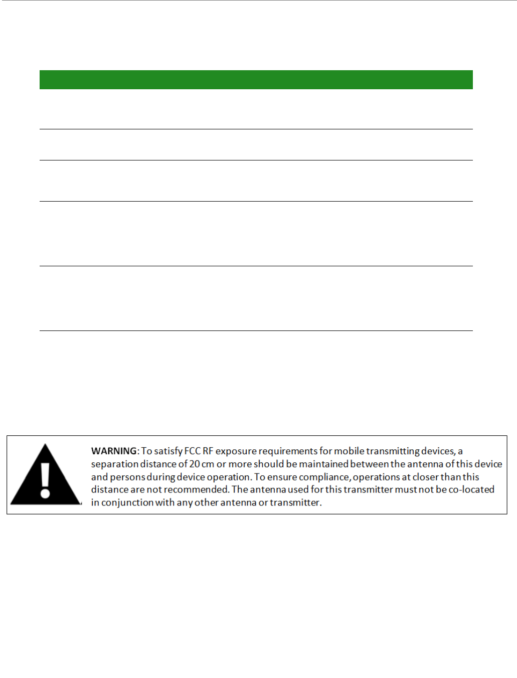
RF Exposure
The preceding statement must be included as a CAUTION statement in OEM product manuals
in order to alert users of FCC RF Exposure compliance.
Europe (ETSI)
The ConnectCard™ for i.MX28 Module has been certified for use in several European
countries. For a complete list, refer to www.digi.com
If the ConnectCard™ for i.MX28 RF Modules are incorporated into a product, the
manufacturer must ensure compliance of the final product to the European harmonized EMC
OMNI-DIRECTIONAL ANTENNAS
Part Number Type
(Description)
Peak Gain Application Cable loss/
Attenuation
required
A24-HASM-450 Dipole
(articulated RPSMA, 2.4GHz antenna)
1.8dBi Fixed/Mobile
29000146 Dipole
(articulated RPSMA, 2.4GHz and 5GHz
antenna)
5dBi Fixed/Mobile
Taoglas PC.11.07.0100A The Stripe Omni-directional antenna 3dBi 2
2.4GHz
4.5dBi @
5GHz
Fixed/Mobile
Taoglas
FXP.830.07.0100C
Dipole 2.6dBi @
2.4GHz
5dBi @
5GHz
Fixed/Mobile
ConnectCore for i.MX28 Hardware Reference
© 2013 Digi International, Inc.. 64
and low-voltage/safety standards. A Declaration of Conformity must be issued for each of
these standards and kept on file as described in Annex II of the R&TTE Directive.
Furthermore, the manufacturer must maintain a copy of the ConnectCard™ for i.MX28
Hardware Reference manual documentation and ensure the final product does not exceed
the specified power ratings, antenna specifications, and/or installation requirements as
specified in the user manual. If any of these specifications are exceeded in the final product,
a submission must be made to a notified body for compliance testing to all required
standards.
OEM Lebeling Requirements
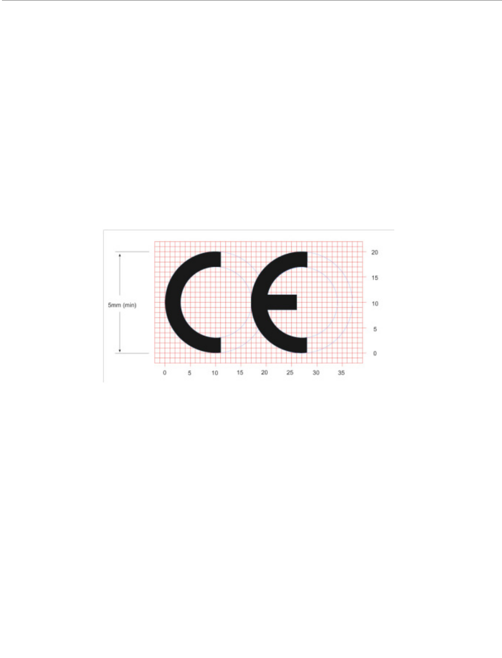
The ‘CE’ marking must be affixed to a visible location on the OEM product.
CE Labeling Requirements
The CE mark shall consist of the initials "CE" taking the following form:
• If the CE marking is reduced or enlarged, the proportions given in the above
graduated drawing must be respected.
• The CE marking must have a height of at least 5mm except where this is not
possible on account of the nature of the apparatus.
• The CE marking must be affixed visibly, legibly, and indelibly.
Restrictions
Declarations of Conformity
Digi has issued Declarations of Conformity for the ConnectCard™ for i.MX28 RF Modules
concerning emissions, EMC and safety. Files can be obtained by contacting Digi Support.
Important Note:
Digi does not list the entire set of standards that must be met for each country. Digi
customers assume full responsibility for learning and meeting the required guidelines for
each country in their distribution market. For more information relating to European
compliance of an OEM product incorporating the ConnectCard™ for i.MX28 RF Module,
contact Digi, or refer to the following web sites:

ConnectCore for i.MX28 Hardware Reference
© 2013 Digi International, Inc.. 65
• CEPT ERC 70-03E - Technical Requirements, European restrictions and general
requirements: Available at www.ero.dk/.
• R&TTE Directive - Equipment requirements, placement on market: Available at
www.ero.dk/.
Approved Antennas
The same antennas have been approved for Europe as stated in the FCC table for use with
the ConnectCard™ for i.MX28 Module.
Canada (IC)
This device complies with Industry Canada license-exempt RSS standard(s). Operation is
subject to the following two conditions: (1) this device may not cause interference, and (2)
this device must accept any interference, including interference that may cause undesired
operation of the device.
Le présent appareil est conforme aux CNR d'Industrie Canada applicables aux appareils radio
exempts de licence. L'exploitation est autorisée aux deux conditions suivantes : (1)
l'appareil ne doit pas produire de brouillage, et (2) l'utilisateur de l'appareil doit accepter
tout brouillage radioélectrique subi, même si le brouillage est susceptible d'en
compromettre le fonctionnement.
Labeling Requirements
Labeling requirements for Industry Canada are similar to those of the FCC. A clearly visible
label on the outside of the final product enclosure must display the following text:
Contains Model ConnectCard™ for i.MX28 Radio, IC: 1846A-CCi.MX28
The integrator is responsible for its product to comply with IC ICES-003 & FCC Part 15, Sub. B
- Unintentional Radiators. ICES-003 is the same as FCC Part 15 Sub. B and Industry Canada
accepts FCC test report or CISPR 22 test report for compliance with ICES-003.
Transmitters with Detachable Antennas
This radio transmitter (IC: 1846A-CCi.MX28) has been approved by Industry Canada to
operate with the antenna types listed in the table above with the maximum permissible gain
and required antenna impedance for each antenna type indicated. Antenna types not
included in this list, having a gain greater than the maximum gain indicated for that type, are
strictly prohibited for use with this device.
Le présent émetteur radio (IC: 1846A-CCi.MX28) a été approuvé par Industrie Canada pour
fonctionner avec les types d'antenne énumérés ci-dessous et ayant un gain admissible
maximal et l'impédance requise pour chaque type d'antenne. Les types d'antenne non inclus
dans cette liste, ou dont le gain est supérieur au gain maximal indiqué, sont strictement
interdits pour l'exploitation de l'émetteur.

ConnectCore for i.MX28 Hardware Reference
© 2013 Digi International, Inc.. 66
Detachable Antenna
Under Industry Canada regulations, this radio transmitter may only operate using an antenna
of a type and maximum (or lesser) gain approved for the transmitter by Industry Canada. To
reduce potential radio interference to other users, the antenna type and its gain should be so
chosen that the equivalent isotropically radiated power (e.i.r.p.) is not more than that
necessary for successful communication.
Conformément à la réglementation d'Industrie Canada, le présent émetteur radio peut
fonctionner avec une antenne d'un type et d'un gain maximal (ou inférieur) approuvé pour
l'émetteur par Industrie Canada. Dans le but de réduire les risques de brouillage
radioélectrique à l'intention des autres utilisateurs, il faut choisir le type d'antenne et son
gain de sorte que la puissance isotrope rayonnée équivalente (p.i.r.e.) ne dépasse pas
l'intensité nécessaire à l'établissement d'une communication satisfaisante.
Australia (C-Tick)
These modules comply with requirements to be used in end products in Australia. All
products with EMC and radio communications must have a registered C-Tick mark.
Registration to use the compliance mark will only be accepted from Australian manufacturers
or importers, or their agent, in Australia.
In order to have a C-Tick mark on an end product, a company must comply with a or b below.
ahave a company presence in Australia.
bhave a company/distributor/agent in Australia that will sponsor the importing of the
end product.
Contact Digi for questions related to locating a contact in Australia.
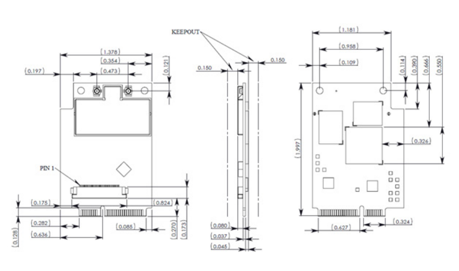
© 2013 Digi International, Inc. 67
Module Specifications
APPENDIX A
Mechanical Specifications
Dimensional Drawing
Environmental Specifications
*Operating temperatures above 65ºC may require additional thermal management
considerations as part of the module integration. See the Thermal Considerations section
in this document for details.
Operating temperature: -40ºC to +85ºC*
Storage temperature: -40ºC to +125ºC
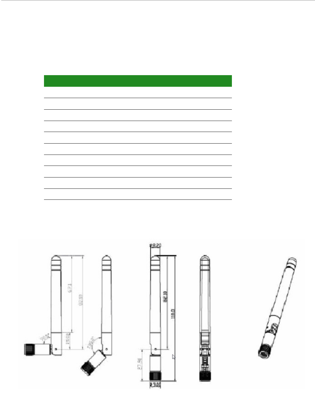
ConnectCore™ for i.MX28 Hardware Reference
© 2013 Digi International, Inc. 68
Network Interface
Digi part number A24-HASM-450
Antenna Attributes
Dimensions
Note:
Dimensions are provided for reference purposes only. The actual antenna may vary.
Specification Attribute
Frequency Range 2.4 - 2.5 GHz
Gain 1.8dBi
VSWR 2.0 Max
Connector Reverse Male SMA (RPSMA)
Impedance 50 Ω
Temperature RP-SMA
Gain -20ºC to +80ºC
Return Loss -9.5dB
Weight 27g
Dimensions 10.6 x 87.4 mm
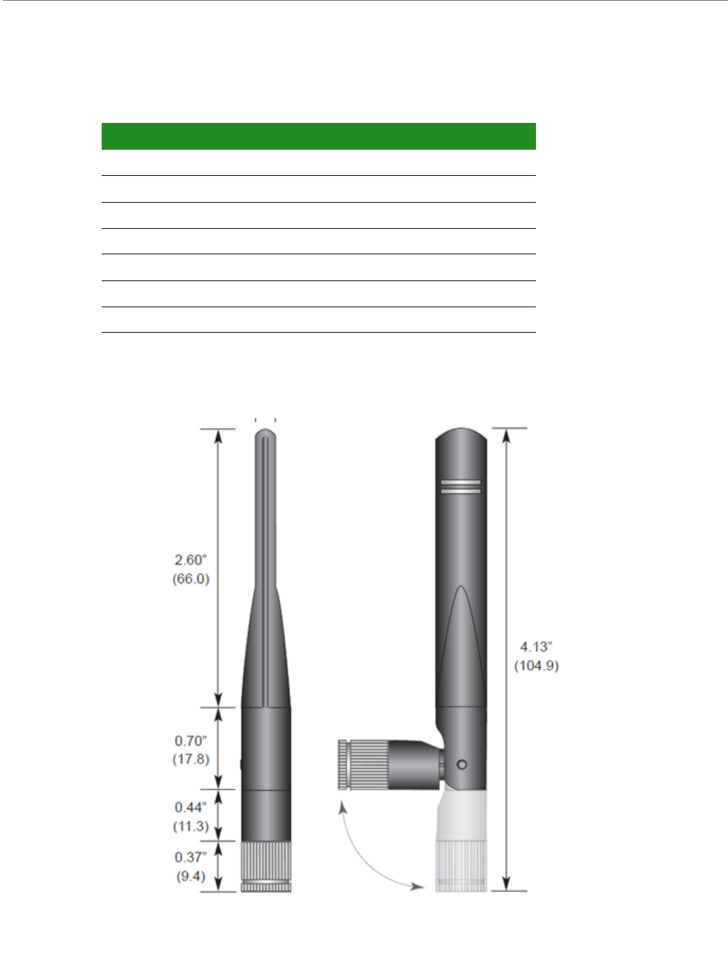
ConnectCore™ for i.MX28 Hardware Reference
© 2013 Digi International, Inc. 69
Digi part number 29000146
Antenna Attributes
Dimensions
Note:
Dimensions are provided for reference purposes only. The actual antenna may vary.
Specification Attribute
Frequency Range 2.4 - 2.5 GHz, 5.15 - 5.825 GHz
Gain 5 dBi Max
VSWR 1.9 Typical
Connector Reverse Male SMA (RPSMA)
Impedance 50 Ω
Temperature Rating -20°C to +80° C
Dimensions 104.9 x 11 mm
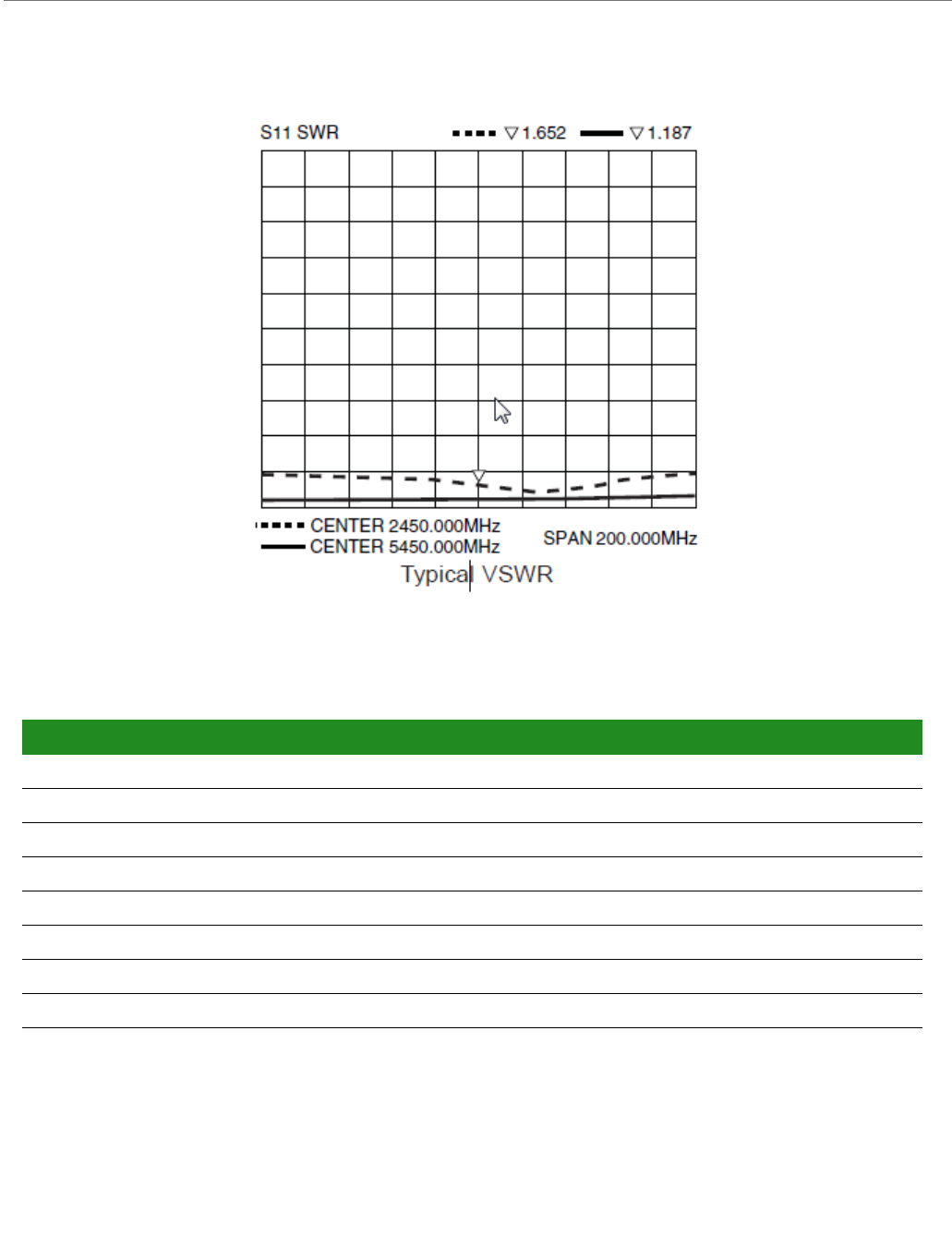
ConnectCore™ for i.MX28 Hardware Reference
© 2013 Digi International, Inc. 70
VSWR Chart
Taoglas PC.11.07.0100A
Antenna Attributes
Specification 2.4 GHzAttribute 5GHz Attribute
Frequency Range 2.4 - 2.5 GHz 4.9 - 5.9 GHz
Peak Gain 3 dBi 4.5 dBi
Average Gain (on plastic) -0.6 dBi -0.5 dBi
VSWR 1.5
Connector u.FL
Impedance 50 Ω
Temperature -40°C to +85° C
Dimensions 66 x 15 mm (excluding cable)
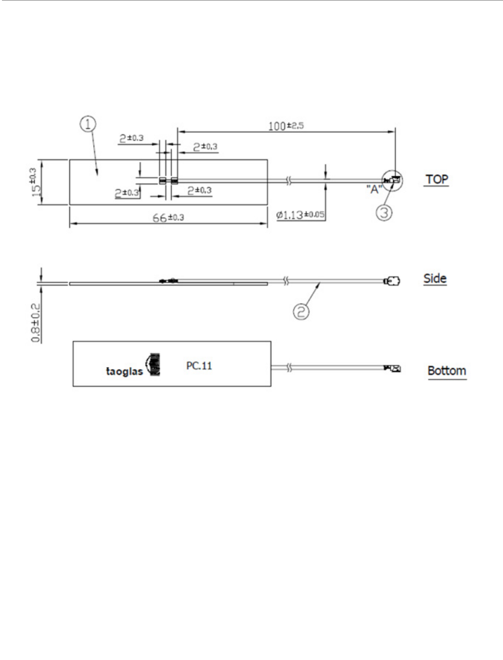
ConnectCore™ for i.MX28 Hardware Reference
© 2013 Digi International, Inc. 71
Dimensions
Note:
Dimensions are provided for reference purposes only. The actual antenna may vary.
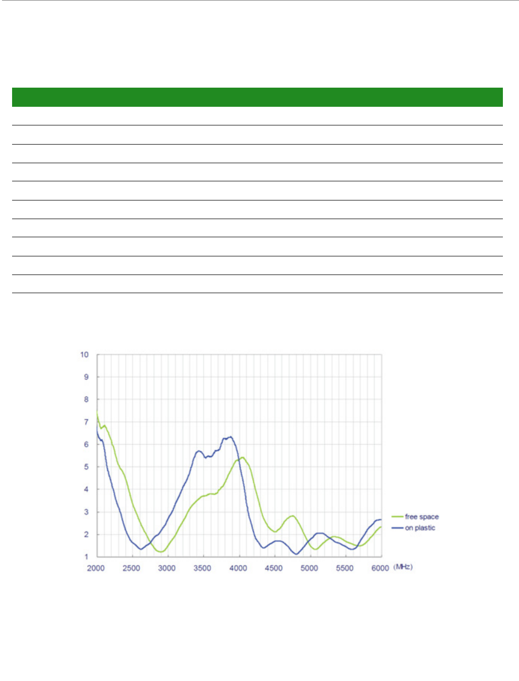
ConnectCore™ for i.MX28 Hardware Reference
© 2013 Digi International, Inc. 72
Taoglas FXP.830.07.0100C
Antenna Attributes
VSWR Chart
Specification 2.4 GHzAttribute 5GHz Attribute
Frequency Range 2.4 - 2.5 GHz 4.9 - 5.9 GHz
Peak Gain (free space) 1.8 dBi 3.6 dBi
Peak Gain (on plastic) 2.6 dBi 5.0 dBi
Average Gain (free space) -3.0 dBi -0.6 dBi
Average Gain (on plastic) -3.0 dBi -0.7 dBi
VSWR (free space, on plastic See chart below
Connector u.FL
Impedance 50 Ω
Temperature -40°C to +85° C
Dimensions 42 x 7 mm (excluding cable)
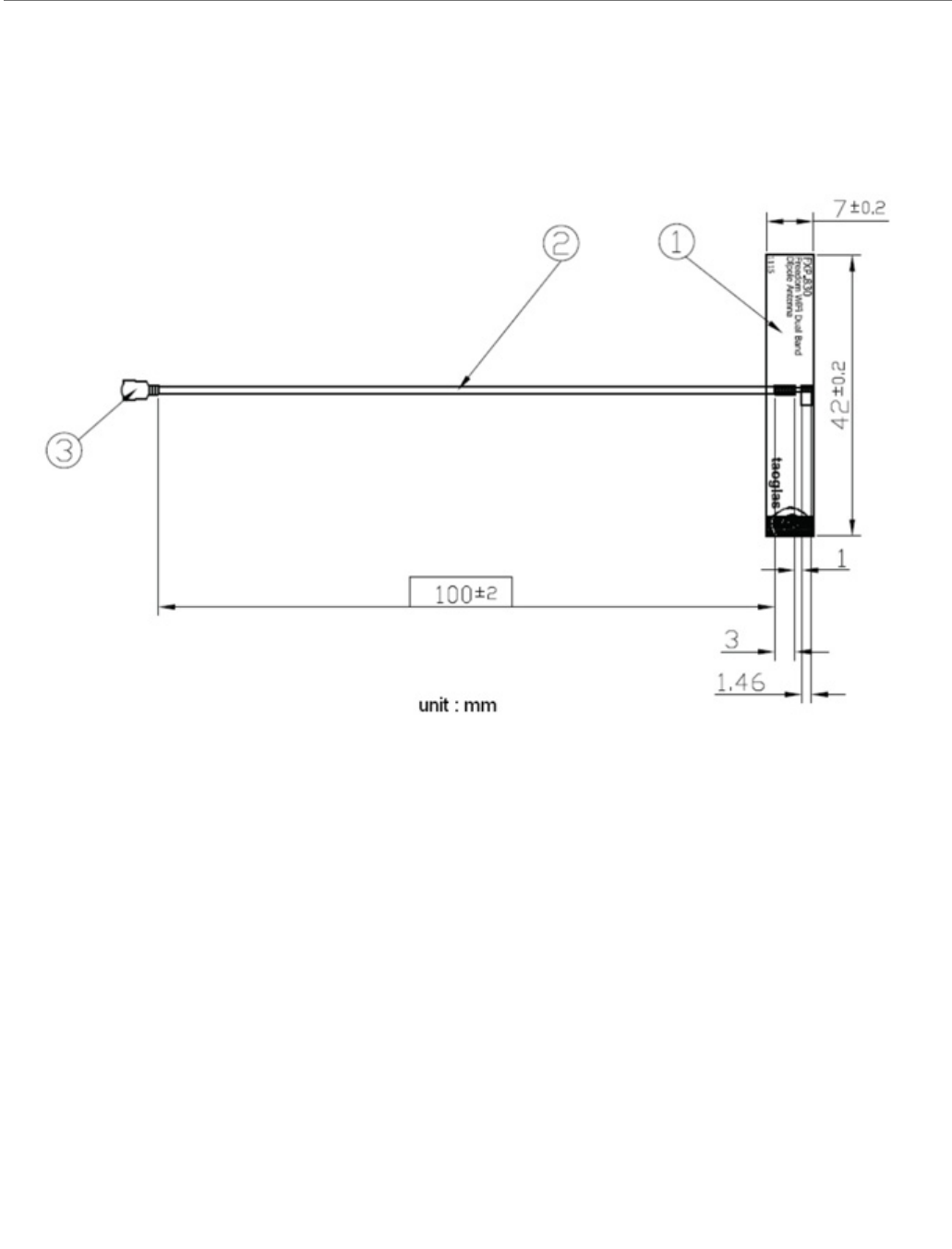
ConnectCore™ for i.MX28 Hardware Reference
© 2013 Digi International, Inc. 73
Dimensions
Note:
Dimensions are provided for reference purposes only. The actual antenna may vary.

ConnectCore™ for i.MX28 Hardware Reference
© 2013 Digi International, Inc. 74
Ethernet 1
Ethernet 2
WLAN
Standard
IEEE 802.11a/b/g/n standards
HT20, and HT40 IEEE 802.11n
Frequency Band
2.40 - 2.50 GHz ( Low Band )
5.18 - 5.825 GHz ( High Band )
Data Rates
802.11b: 1, 2, 5.5, 11 Mbps
802.11a/g: 6, 9, 12, 18, 24, 35, 48, 54 Mbps
802.11n HT20 FGI: 6.5, 13, 19.5, 26, 39, 52, 58.5, 65 Mbps
802.11n HT20 HGI: 7.2, 14.4, 21.7, 29.9, 43.3, 57.8, 65, 72.2 Mbps
802.11n HT40 FGI (5GHz only): 13.5, 27, 40.5, 54, 81, 108, 121.5, 135 Mbps
802.11n HT40 HGI (5GHz only): 15, 30, 45, 60, 90, 120, 135, 150 Mbps
Standard: IEEE802.3
Physical layer: 10/100Base
Data rate: 10/100 Mbps
Standard: IEEE802.3
Physical layer: 10/100Base
Data rate: 10/100 Mbps

ConnectCore™ for i.MX28 Hardware Reference
© 2013 Digi International, Inc. 75
Modulation
Security
Cisco CCXv4 ASD
WAPI (for China)
WPS
WEP
WPA
WPA2
Mode Data
Rate
Modulation Mode Data
Rate
Modulation Mode Data
Rate
Modulation
802.11b 1 DBPSK 802.11g 6 BPSK 802.11a 6 BPSK
2 DQPSK 9 BPSK 9 BPSK
5.5 CCK 12 QPSK 12 QPSK
11 CCK 18 QPSK 18 QPSK
24 16-QAM 24 16-QAM
35 16-QAM 35 16-QAM
48 64-QAM 48 64-QAM
54 64-QAM 54 64-QAM
Mode MCS Modulation Data Rate
802.11n HT20 (2.4GHz and 5GHz) HT40 (5GHz only)
FGI HGI FGI HGI
MCS0 BPSK 6.5 7.2 13.5 15
MCS1 QPSK 13 14.4 27 30
MCS2 QPSK 19.5 21.7 40.5 45
MCS3 16-QAM 26 29.9 54 60
MCS4 16-QAM 39 43.3 81 90
MCS5 64-QAM 52 57.8 108 120
MCS6 64-QAM 58.5 65 121.5 135
MCS7 64-QAM 65 72.2 135 150

ConnectCore™ for i.MX28 Hardware Reference
© 2013 Digi International, Inc. 76
Frequency Bands
US, Canda
2.412 to 2.462 GHz; 11 channels
5.180 to 5.320 GHz; 8 channels
5.500 to 5.700 GHz, 8 channels (excludes 5.600 to 5.650 GHz)
5.745 to 5.825 GHz; 5 channels
Europe
2.412 to 2.472 GHz; 13 channels
5.180 to 5.320 GHz; 8 channels
5.500 to 5.700 GHz, 8 channels (excludes 5.600 to 5.640 GHz)
Australia, New Zealand
2.412 to 2.462 GHz; 11 channels
5.180 to 5.320 GHz; 8 channels
5.745 to 5.825 GHz; 5 channels
Japan
2.412 to 2.472 GHz; 13 channels
5.180 to 5.320 GHz; 8 channels
5.500 to 5.700 GHz; 11 channels

ConnectCore™ for i.MX28 Hardware Reference
© 2013 Digi International, Inc. 77
5GHz HT20 AND HT40 Channels Available
Channel
Number
Frequency Mode Secondary Channel Allowed
36 2180 HT40 PLUS
38 5190 HT20
40 5200 HT40 MINUS
44 5220 HT40 PLUS
46 5230 HT20
48 5240 HT40 MINUS
52 5260 HT40 PLUS
54 5270 HT20
56 5280 HT40 MINUS
60 5300 HT40 PLUS
62 5310 HT20
64 5320 HT40 MINUS
100 5500 HT40 PLUS
102 5510 HT20
104 5520 HT40 MINUS
108 5540 HT40 PLUS
110 5550 HT20
112 5560 HT40 MINUS
116 5580 HT40 PLUS
118 5590 HT20
120 5600 HT40 MINUS
124 5620 HT40 PLUS
126 5630 HT20
128 5640 HT40 MINUS
132 5660 HT40 PLUS
134 5670 HT20
136 5680 HT40 MINUS
140 5700 HT20
149 5745 HT40 PLUS
151 5755 HT20
153 5765 HT40 MINUS

ConnectCore™ for i.MX28 Hardware Reference
© 2013 Digi International, Inc. 78
Receive Sensitivity
Electrical Characteristics
Absolute Maximum Ratings
Note that other nterfaces not specifically mentioned are the same as GPIOs.
157 5785 HT40 PLUS
159 5795 HT20
161 5805 HT40 MINUS
165 5825 HT20
Network Type Sensitivity
802.11 b -88 dBm
802.11 g -88 dBm
802.11 n (2.4 GHz) -89 dBm
802.11 a -90 dBm
802.11 n (5 GHz, 20 MHz Bandwidth) -90 dBm
802.11 n (5 GHz, 40 MHz Bandwidth) -86 dBm
Parameter Min Max Unit
VDD_5V -0.3 5.25 V
Battery -0.3 4.242 V
Pswitch -0.3 Battery/2 V
USB DP and DN -0.3 3.63 V
GPIO -0.3 3.6 V
Ethernet TX +/- and RX +/- -0.5 4 V
Channel
Number
Frequency Mode Secondary Channel Allowed

ConnectCore™ for i.MX28 Hardware Reference
© 2013 Digi International, Inc. 79
Voltage Supplies
Supply Current
Tra nsm it P owe r
GPIO DC Parameters
Parameter Min Typ Max Unit
5V Supply 4.75 55.25 V
Battery Supply 3.4 4.2 V
Settings Supply Current
Wi-Fi 2.4 GHz Transmit, CPU 545 MHz, 50%,
UART active
475 mA
Wi-Fi 5 GHz Transmit, CPU 545 MHz, 50%,
UART active
600 mA
Wi-Fi 5 GHz Recieve CPU Idle (Auto Slow) 300 mA
Wi-Fi 2.4 GHz Recieve CPU Idle (Auto Slow) 325 mA
Network Type Transmit Power
802.11 b 10.5 dBm
802.11 g/n 11 dBm
802.11 a/n 13 dBm
Parameter Min Max Unit
Input Voltage high (DC) 23.3 V
Input Voltage low (DC) -0.8 V
Output Voltage high (DC) 4.64 - V
Output Voltage low (DC) -0.4 V
Output Source Current (DC) gpio, gpio_f and gpio_nobs
4mA setting 3.8 6.8 mA
8mA setting 7.6 13.6 mA
12mA setting 12.1 24.5 mA
Output Sink Current (DC) gpio, gpio_f, and gpio_nobs
4mA setting 48.1 mA
8mA setting 8.1 16.4 mA
12mA setting 12.1 24.5 mA

ConnectCore™ for i.MX28 Hardware Reference
© 2013 Digi International, Inc. 80
See the Freescale i.MX28 data sheet and manual for full details.
Agency Approvals
Output Source Current (DC) gpio_clk
8mA setting 7.6 13.6 mA
16mA setting 15.2 27.2 mA
Output Sink Current (DC) gpio_clk
8mA setting 8.1 15.4 mA
16mA setting 16.2 30.6 mA
10k pull-up resistance 812 kΩ
47k pull-up resistance 39 56 kΩ
Specification ConnectCard™ for i.MX28
United States (FCC Part 15.247) FCC ID: MCQ-CCIMX28
Industry Canada (IC) IC: 1846A-CCIMX28
Europe (DC) ETSI
Australia Pending
Japan Pending
UR Pending
VCCI Pending
Parameter Min Max Unit
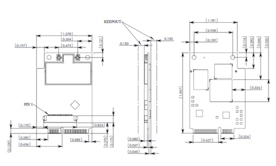
© 2013 Digi International, Inc. 81
Module Dimensions
APPENDIX B
© 2013 Digi International, Inc. 82
Change Log
APPENDIX C
The following changes were made to this document in the revisions listed below.
Revision 0.1
Creation.
Revision 0.2
Correction of FCC and IC approval IDs.