Digi CCIMX6 ConnectCore6 (i.MX6) User Manual Framemaker Book
Digi International Inc ConnectCore6 (i.MX6) Framemaker Book
UserManual.wiki
>
Digi
>
CCIMX6 User Manual
User Manual
Navigation menu
Upload a User Manual
Namespaces
Wiki Guide
HTML
PDF
Info
Views
User Manual
Discussion / Help
Navigation

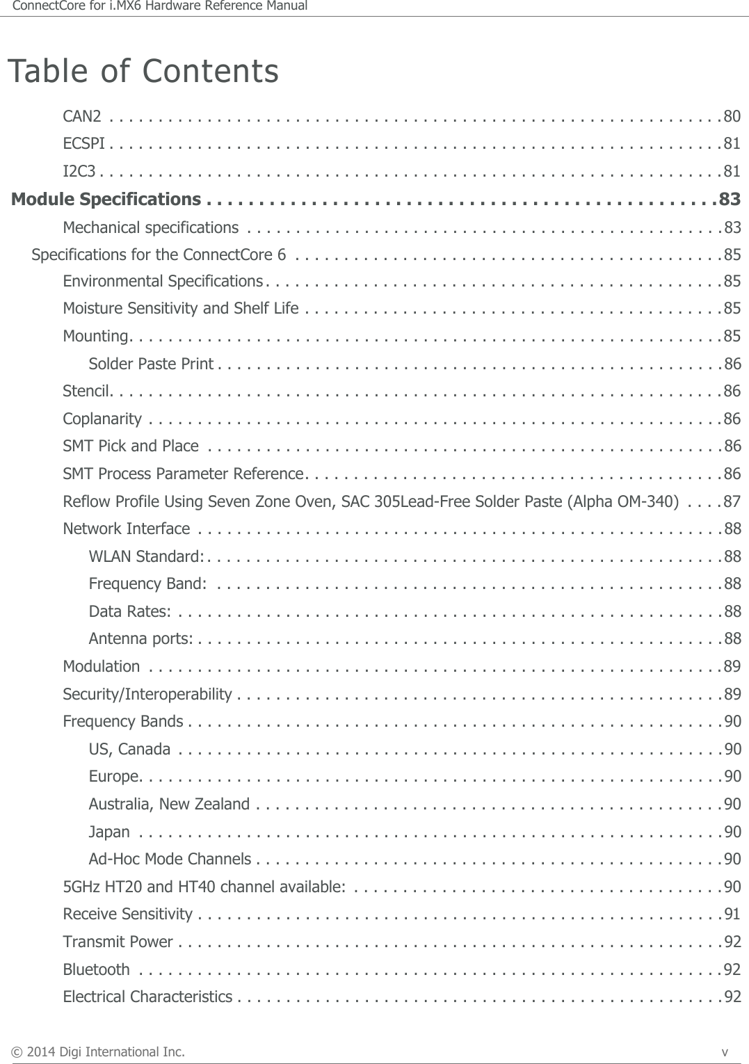
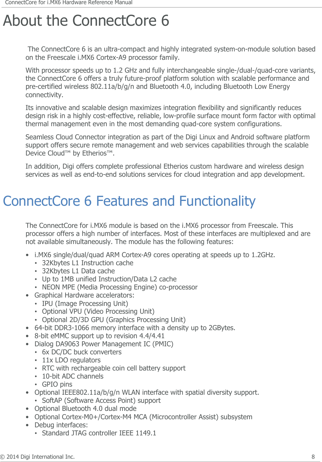
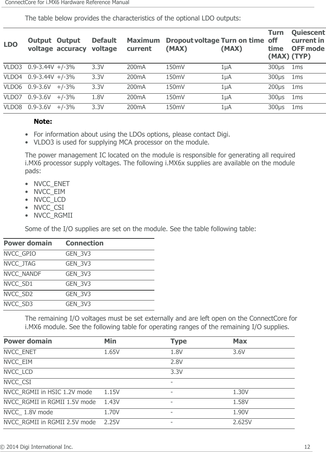
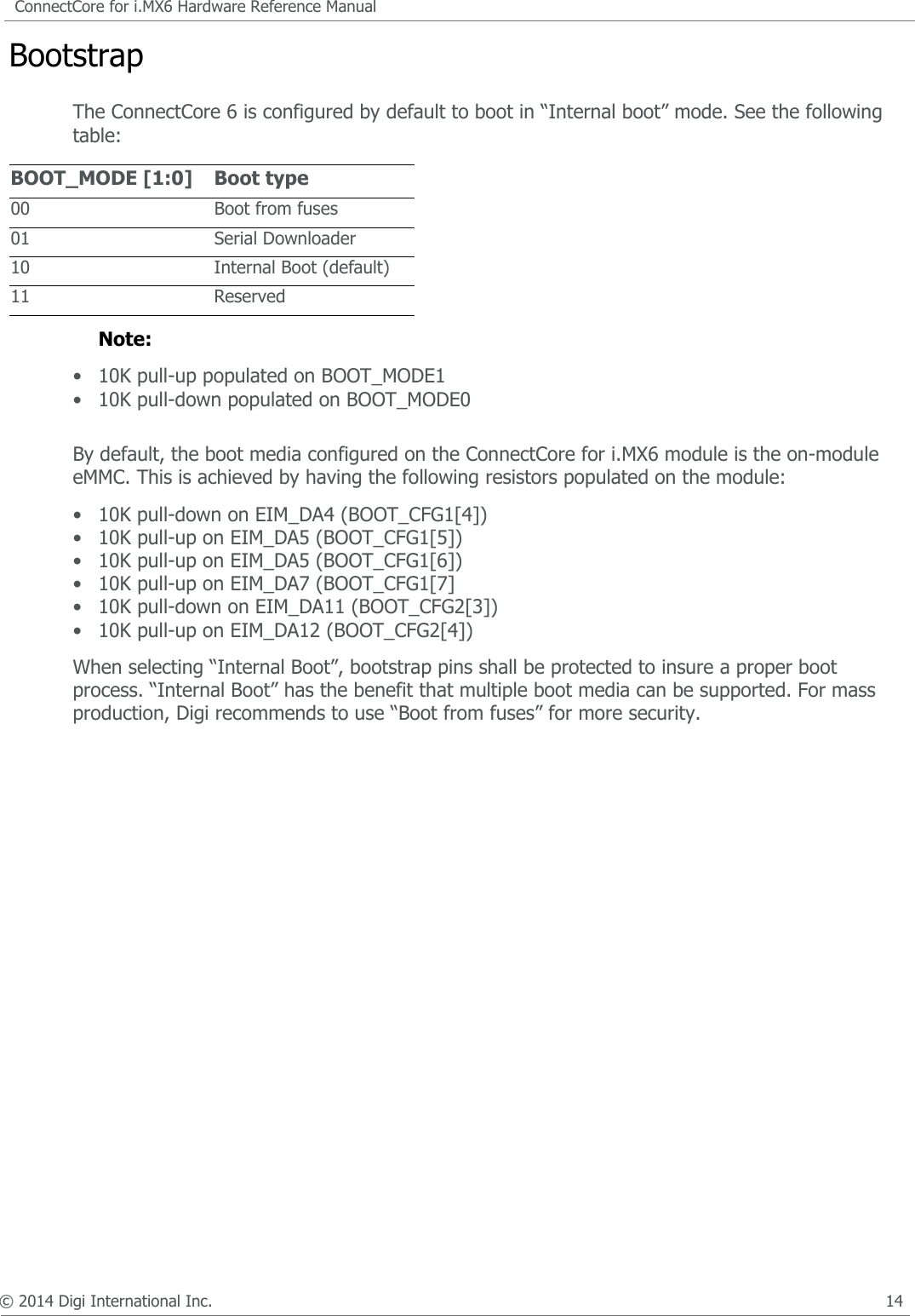
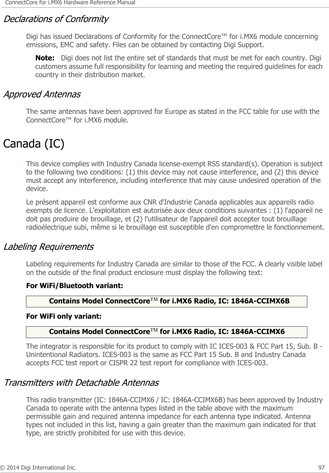
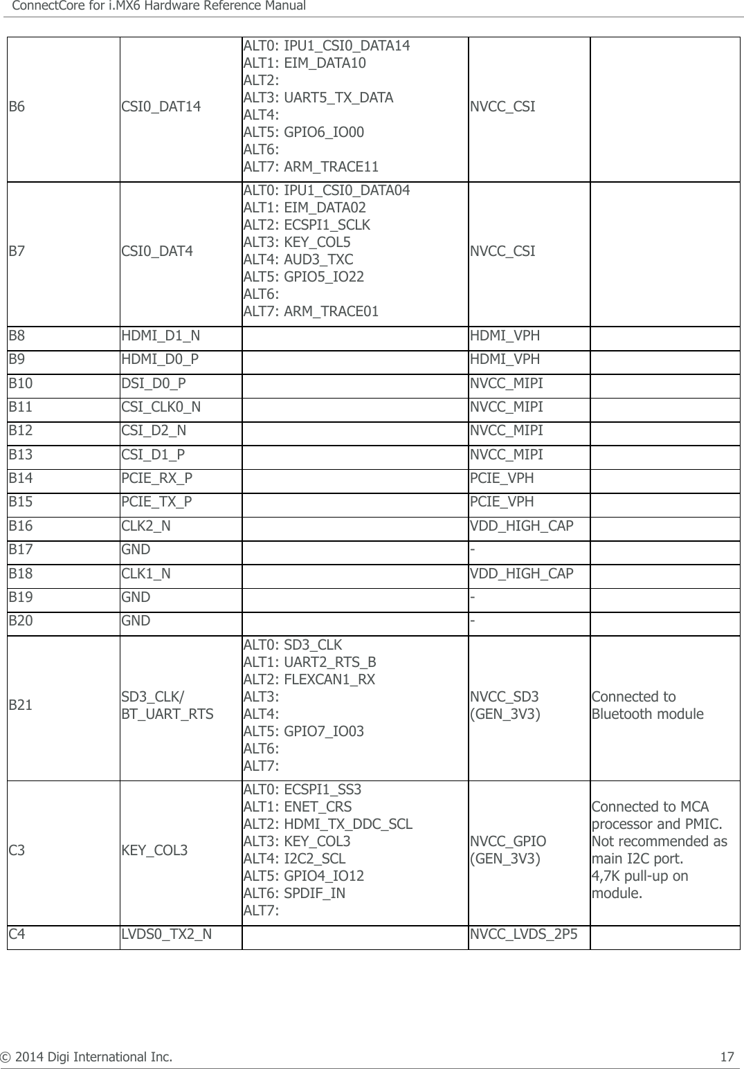
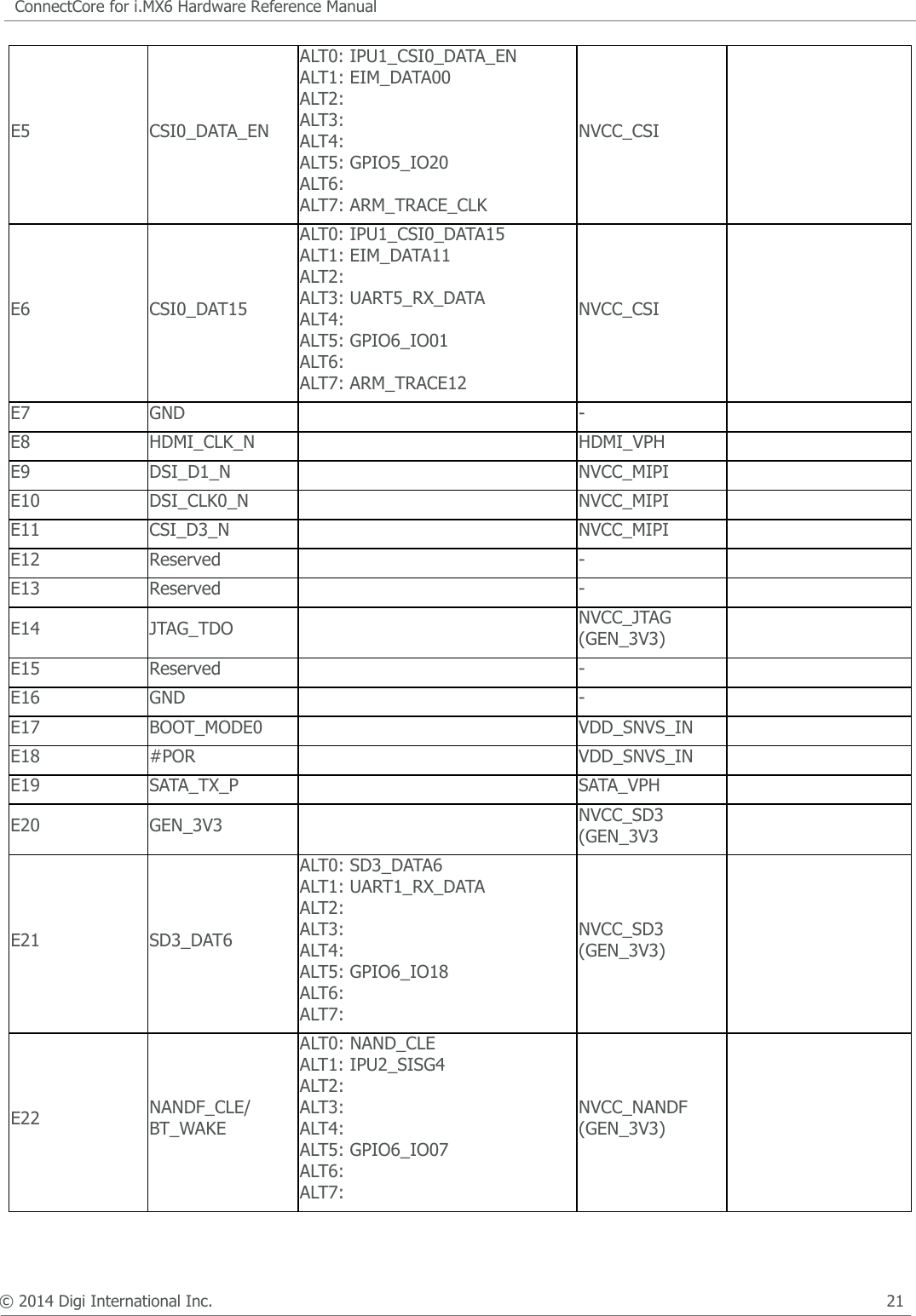
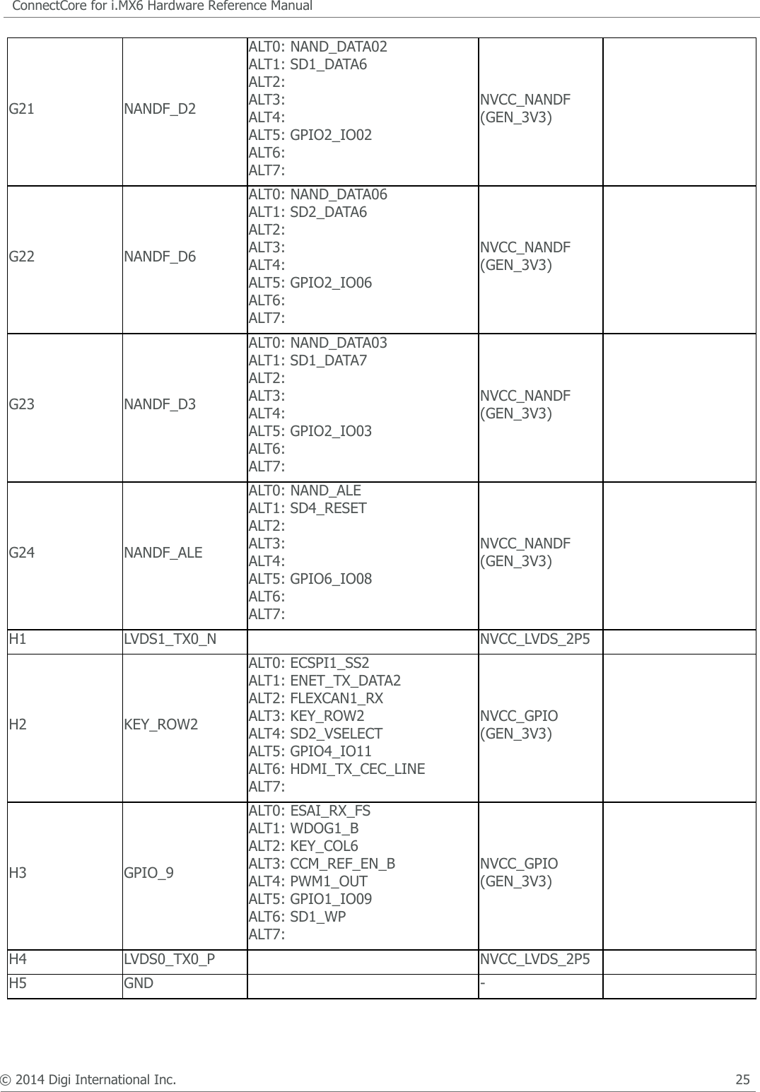
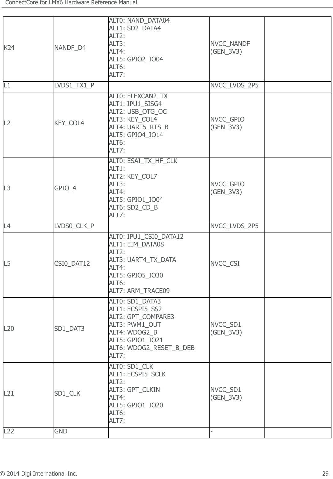
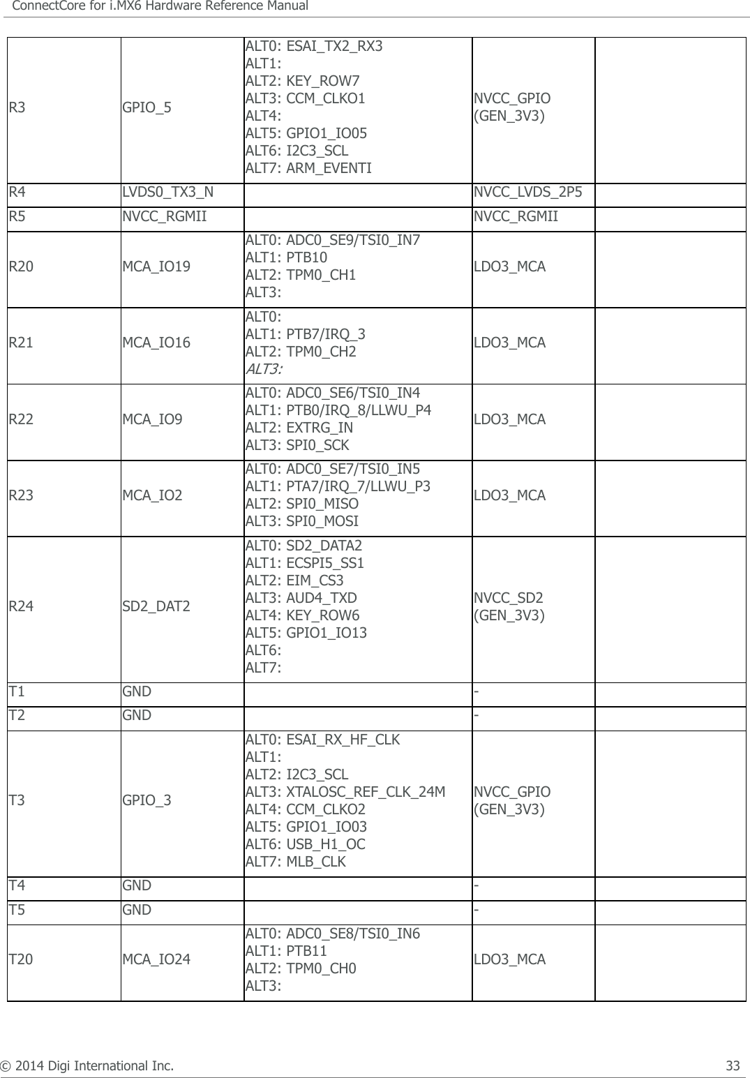
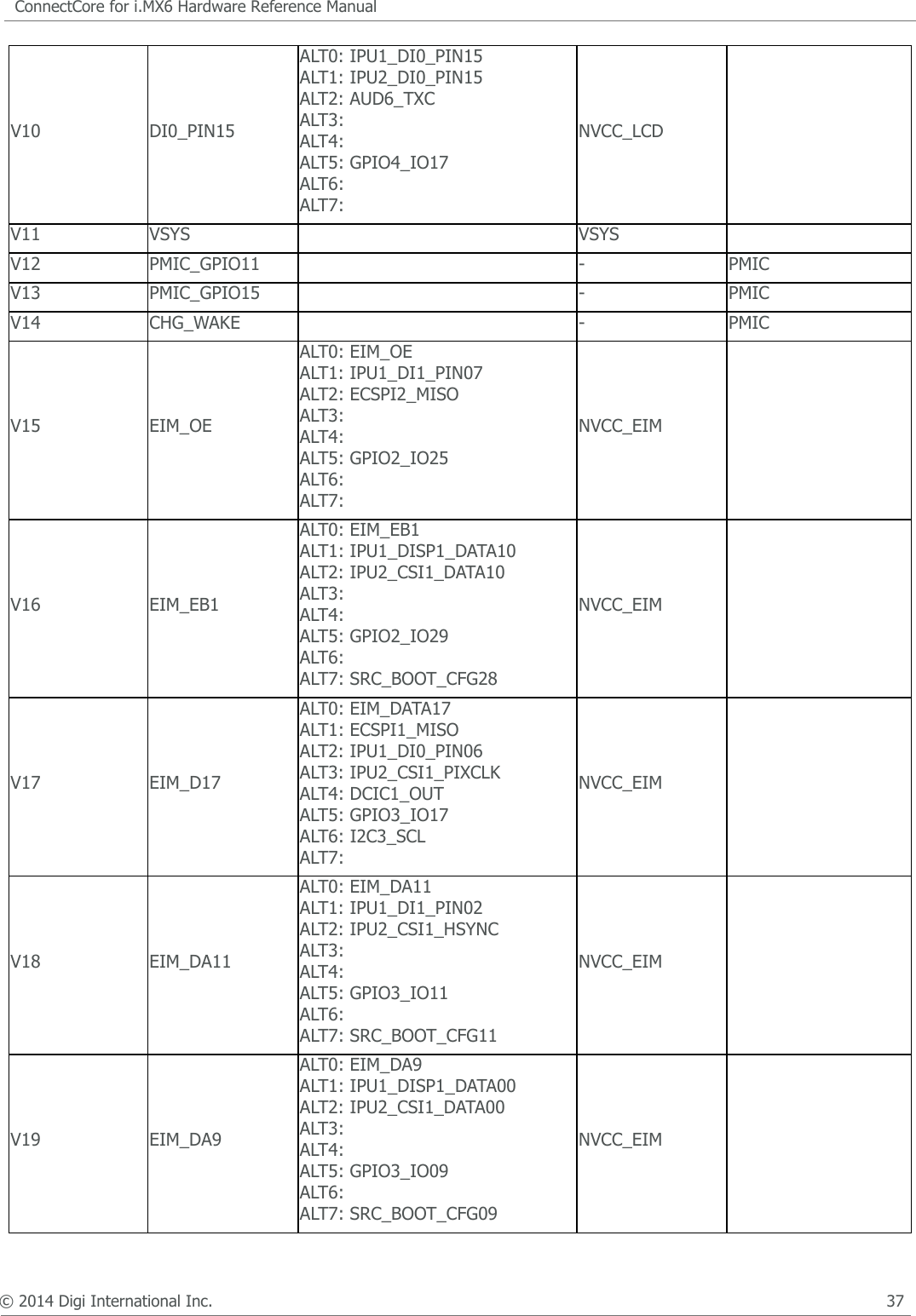
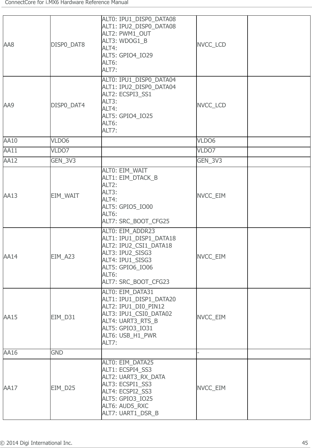
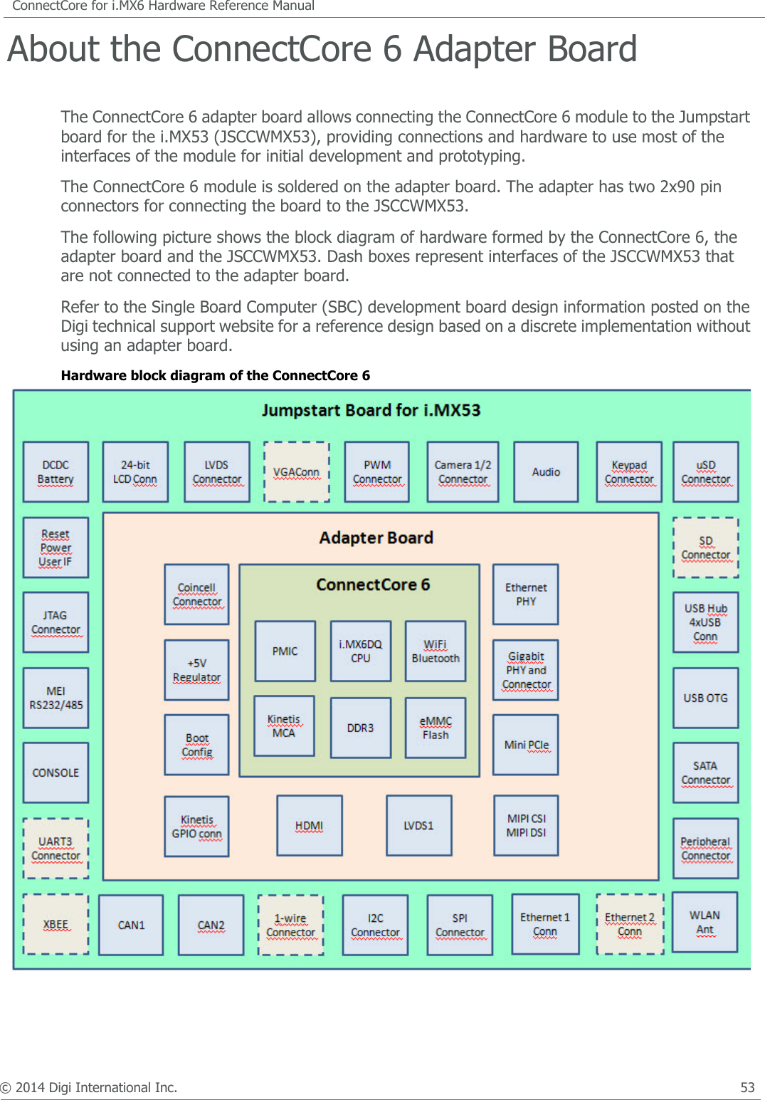
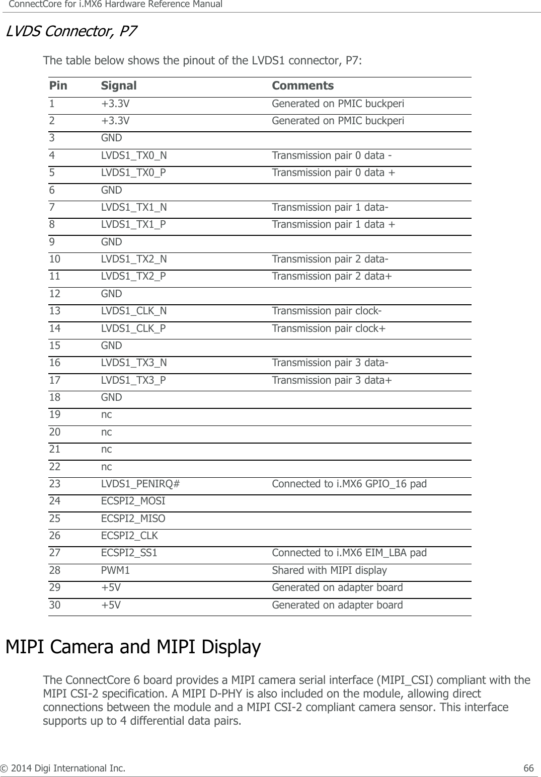
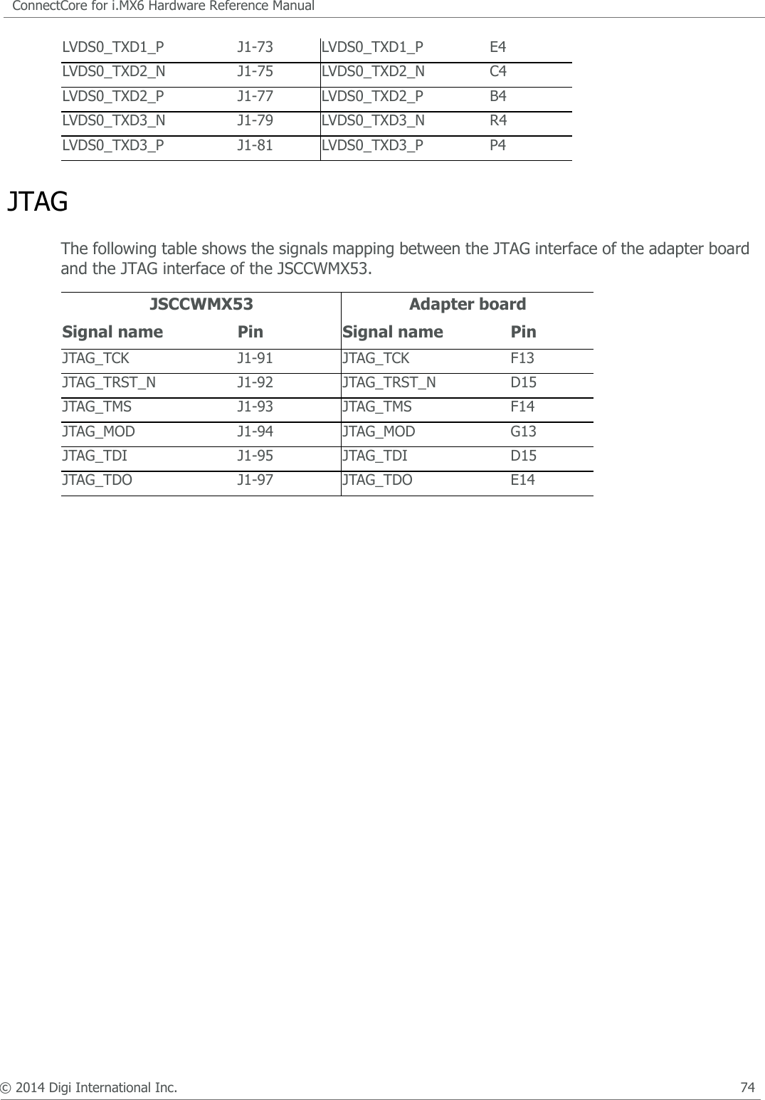
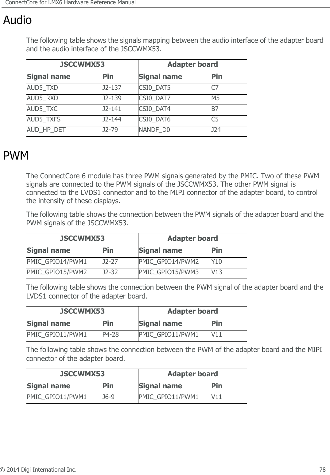
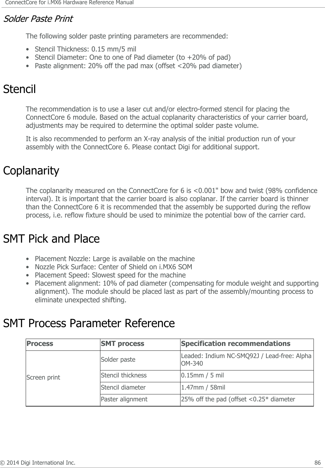
![© 2014 Digi International Inc. 14ConnectCore for i.MX6 Hardware Reference ManualBootstrapThe ConnectCore 6 is configured by default to boot in “Internal boot” mode. See the following table:Note: • 10K pull-up populated on BOOT_MODE1• 10K pull-down populated on BOOT_MODE0By default, the boot media configured on the ConnectCore for i.MX6 module is the on-module eMMC. This is achieved by having the following resistors populated on the module:• 10K pull-down on EIM_DA4 (BOOT_CFG1[4])• 10K pull-up on EIM_DA5 (BOOT_CFG1[5])• 10K pull-up on EIM_DA5 (BOOT_CFG1[6])• 10K pull-up on EIM_DA7 (BOOT_CFG1[7]• 10K pull-down on EIM_DA11 (BOOT_CFG2[3])• 10K pull-up on EIM_DA12 (BOOT_CFG2[4])When selecting “Internal Boot”, bootstrap pins shall be protected to insure a proper boot process. “Internal Boot” has the benefit that multiple boot media can be supported. For mass production, Digi recommends to use “Boot from fuses” for more security.BOOT_MODE [1:0] Boot type00 Boot from fuses01 Serial Downloader10 Internal Boot (default)11 Reserved](https://usermanual.wiki/Digi/CCIMX6/User-Guide-2417064-Page-16.png)
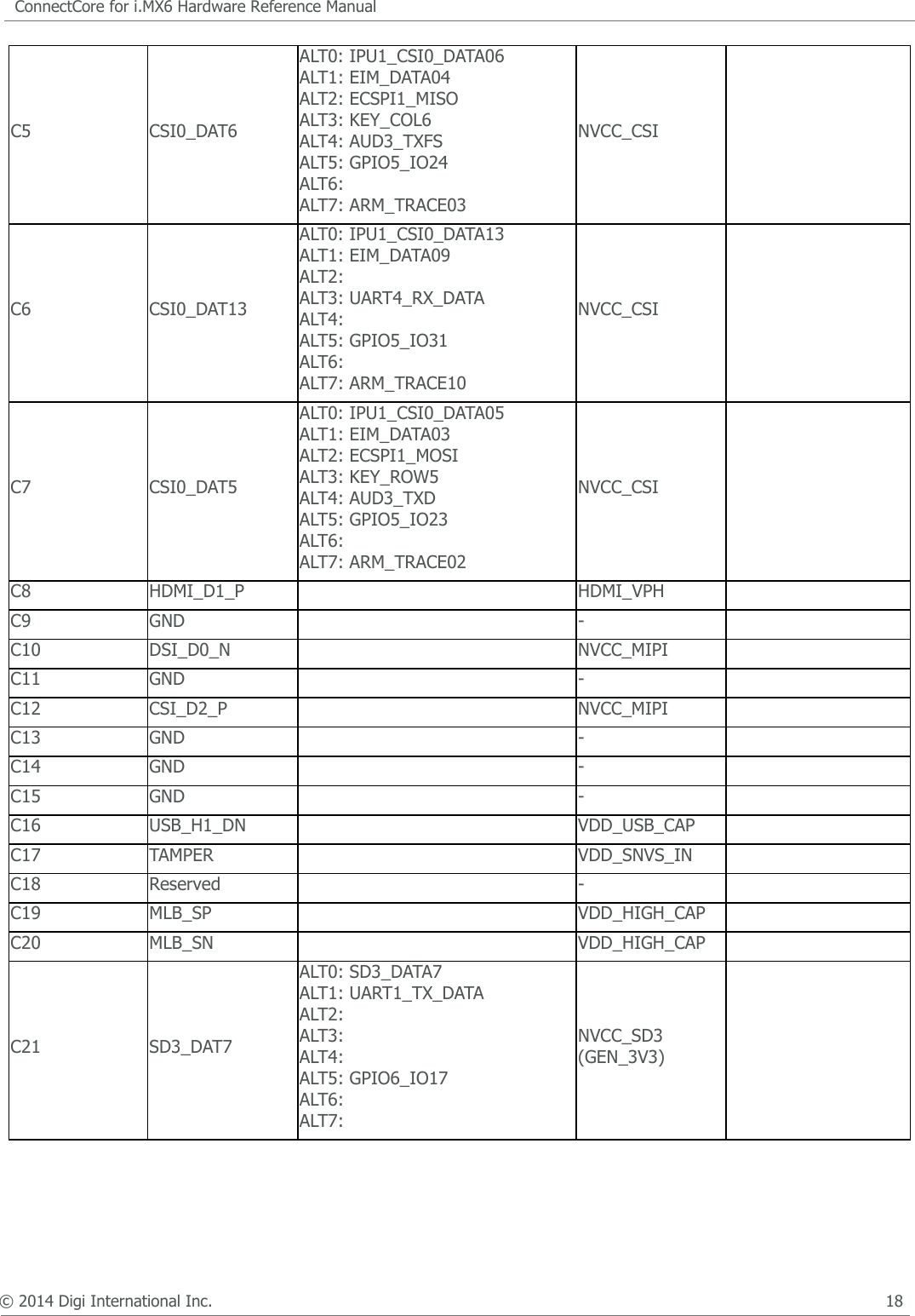
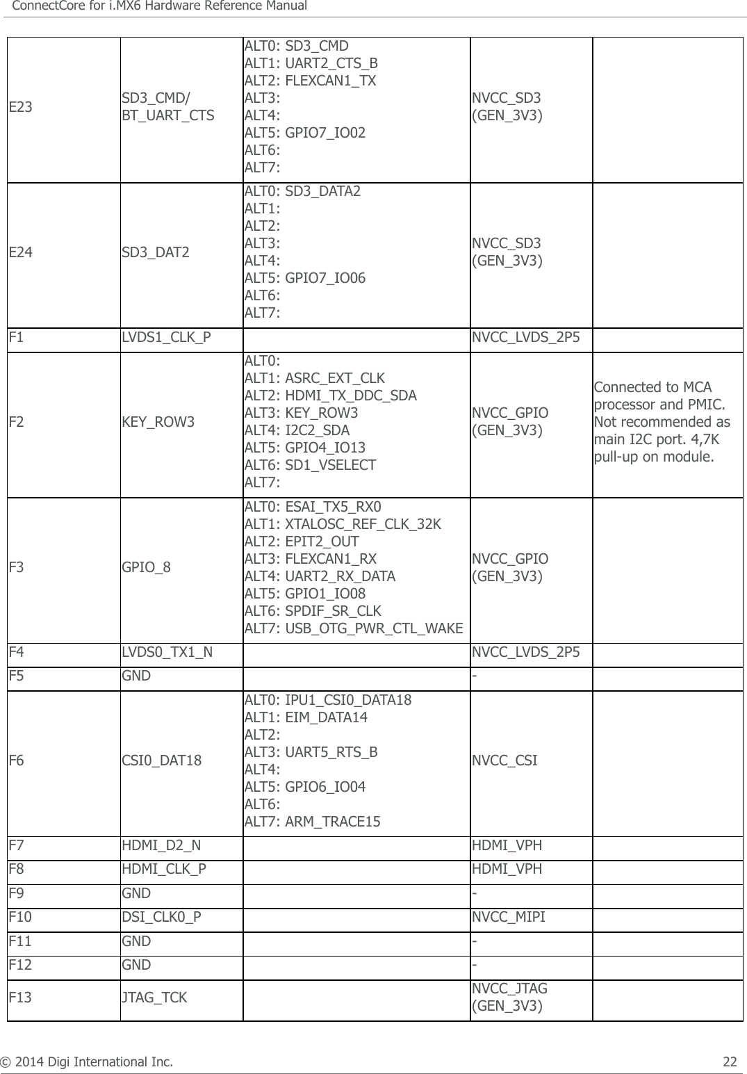
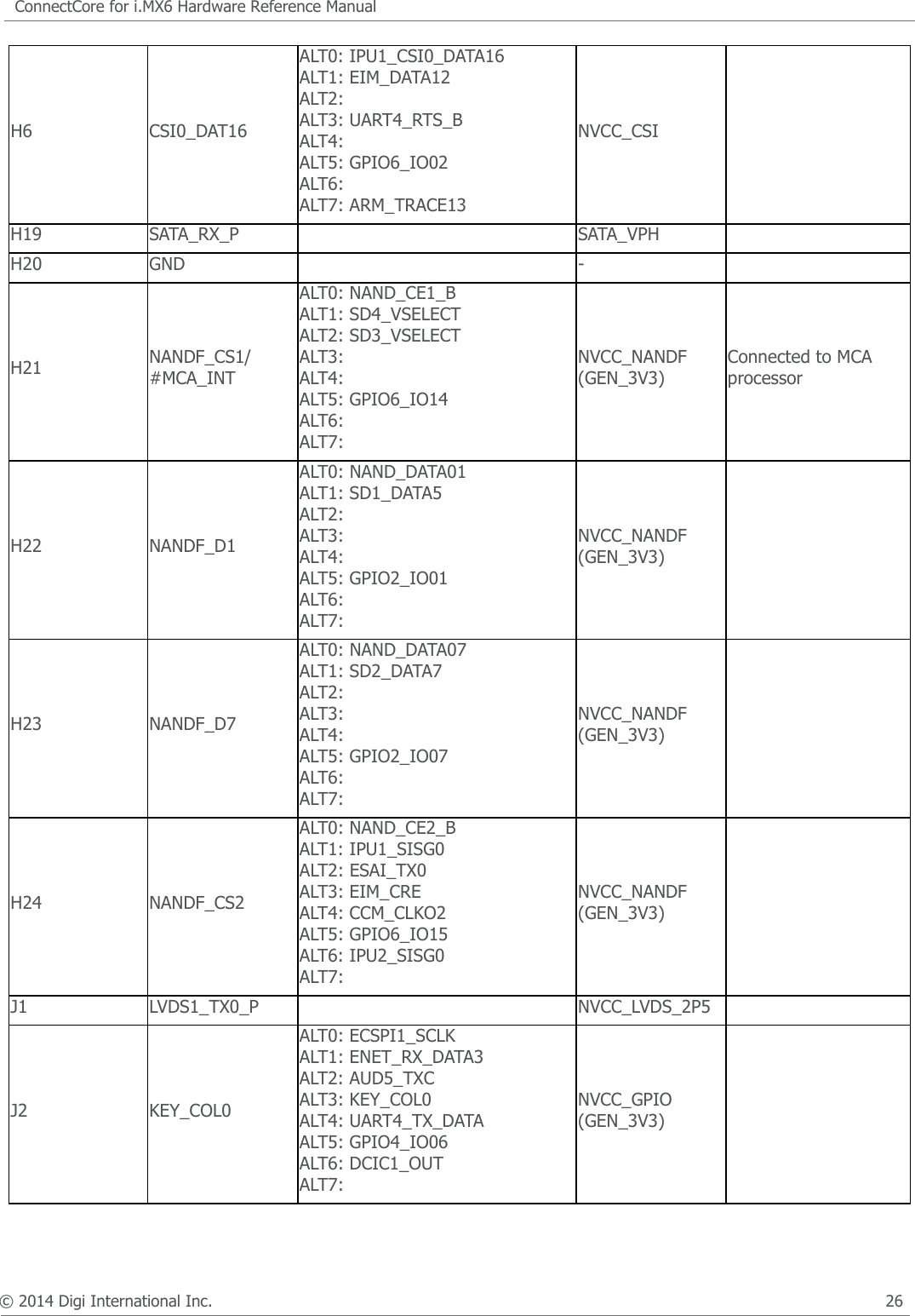
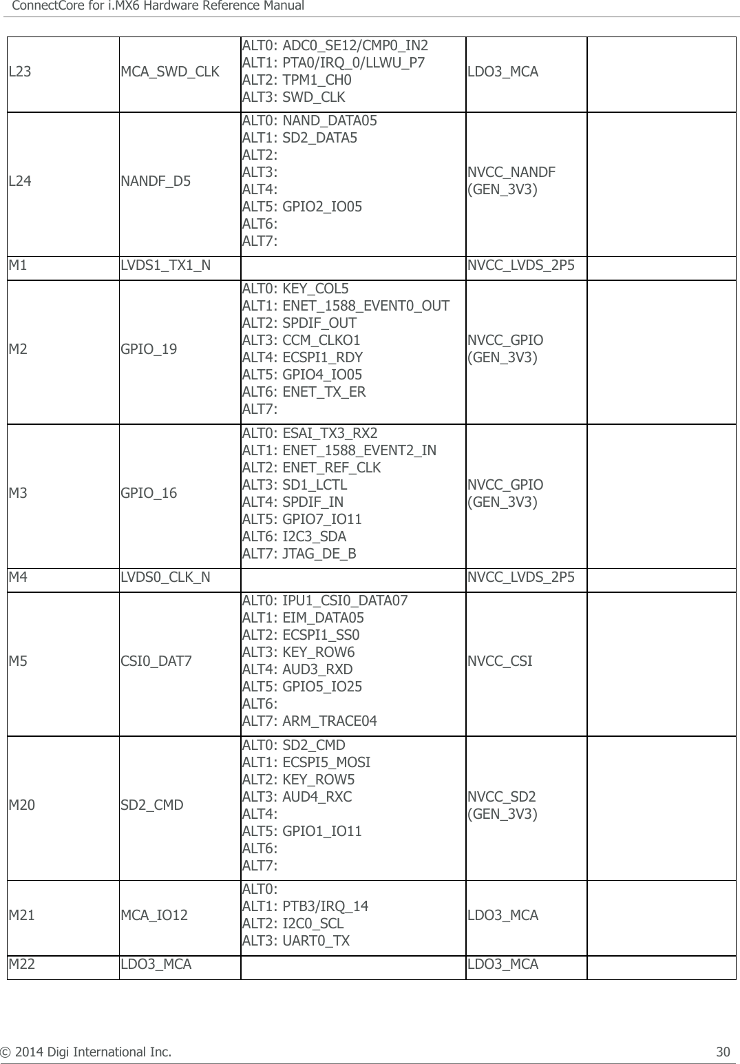
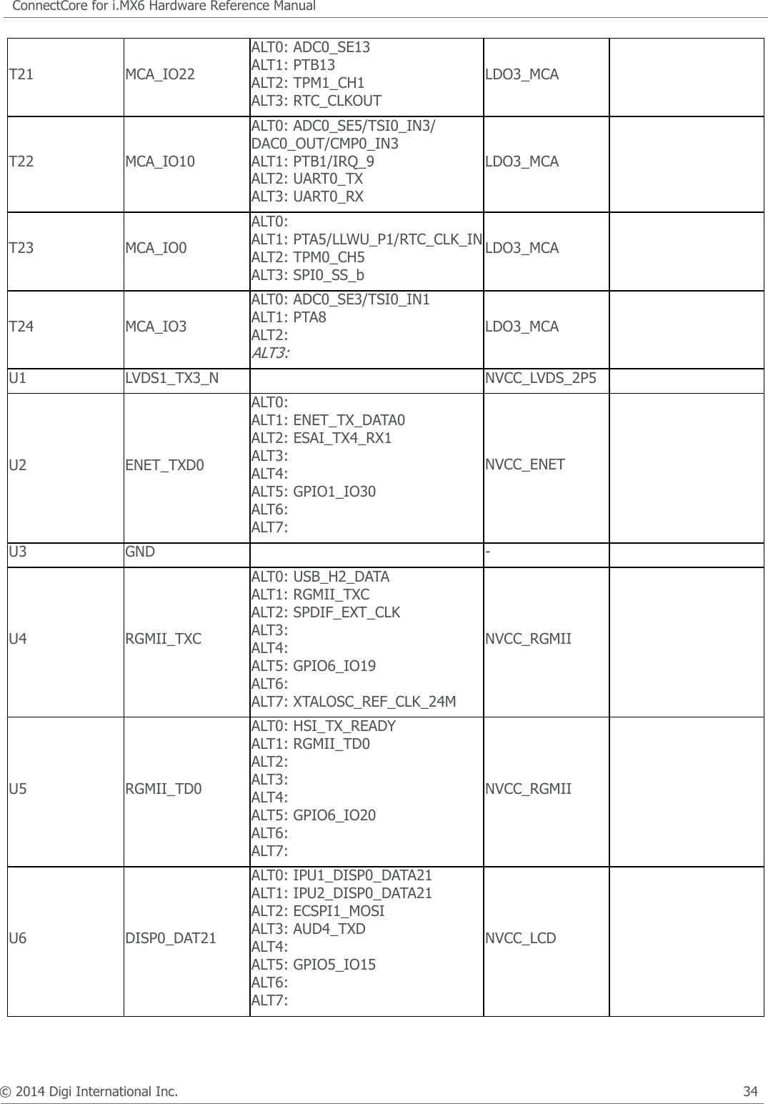
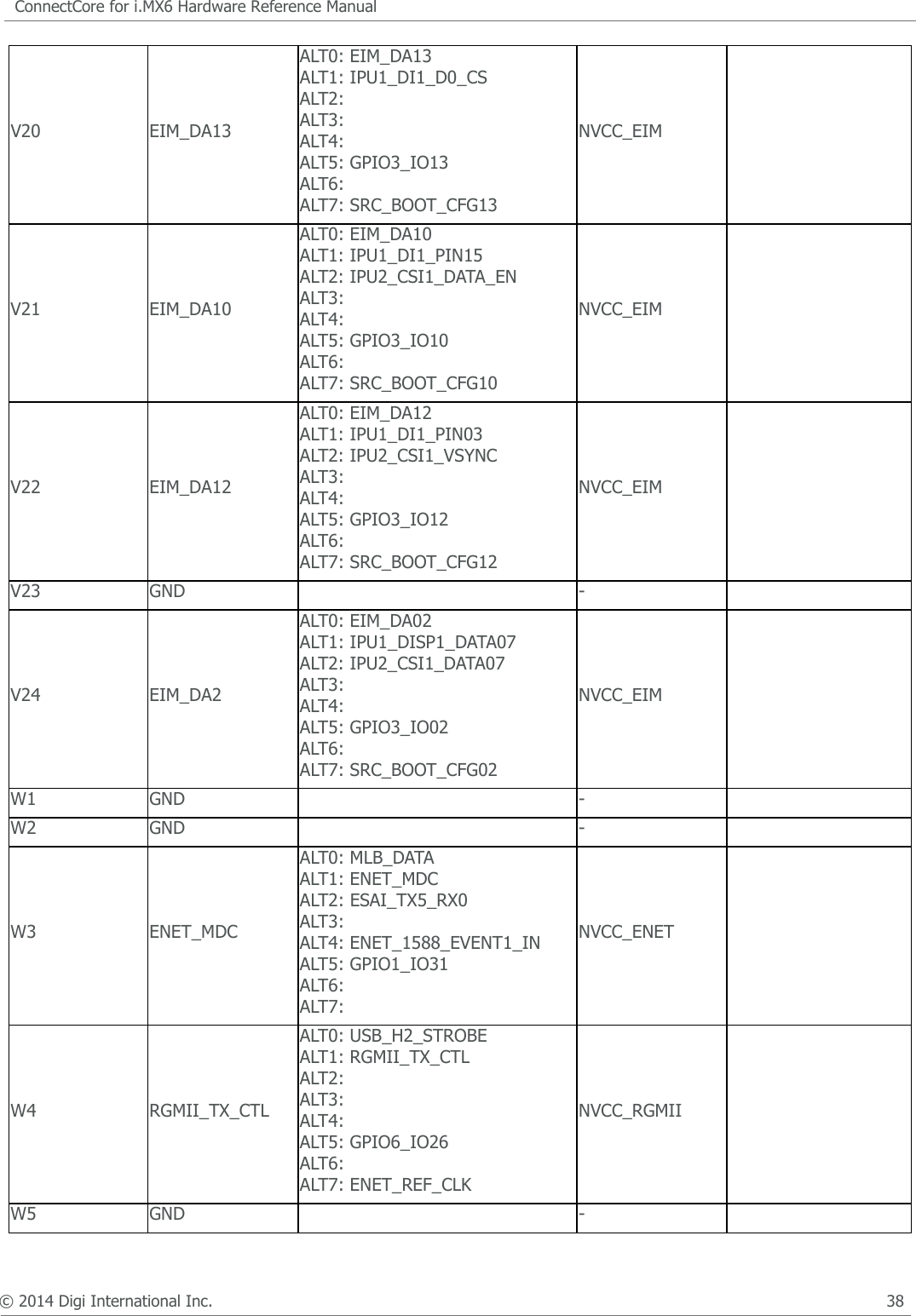
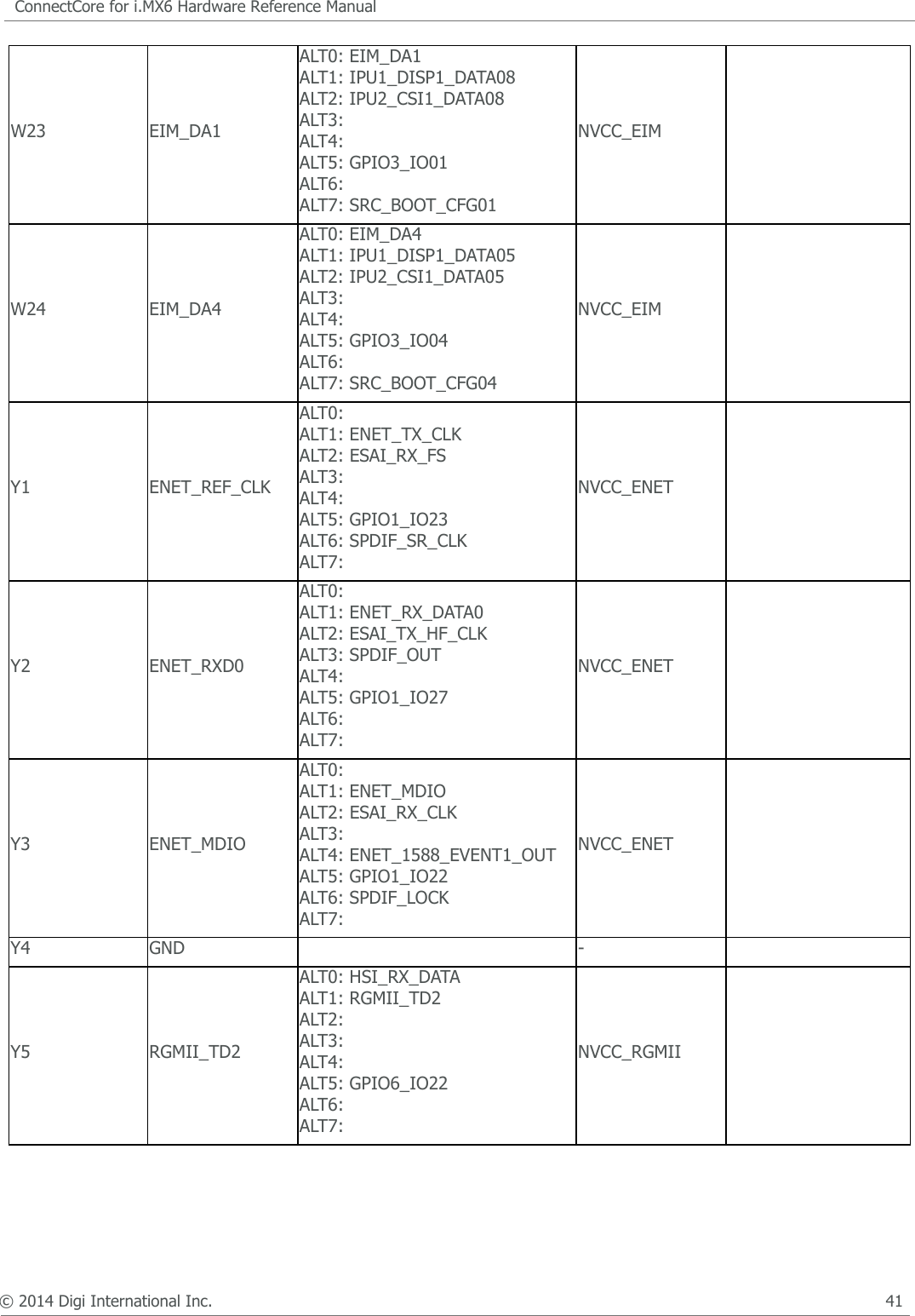
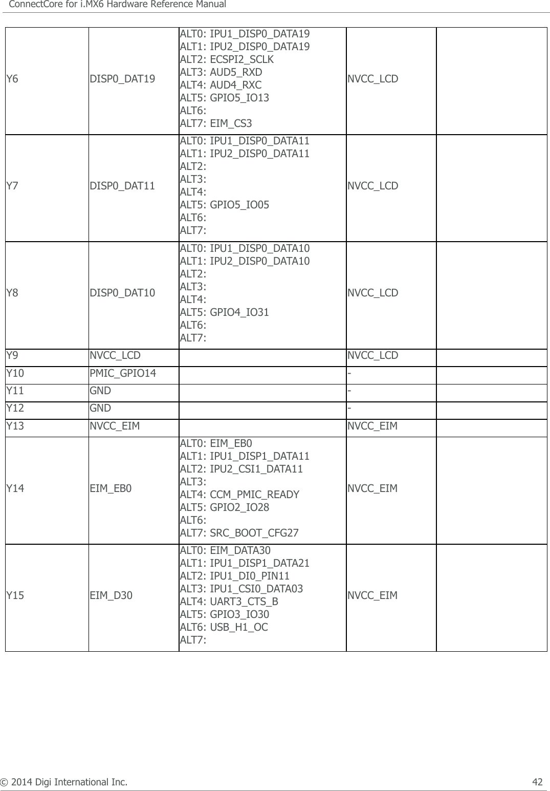
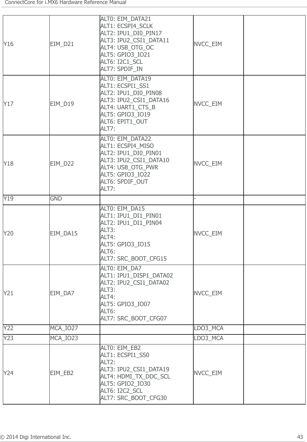
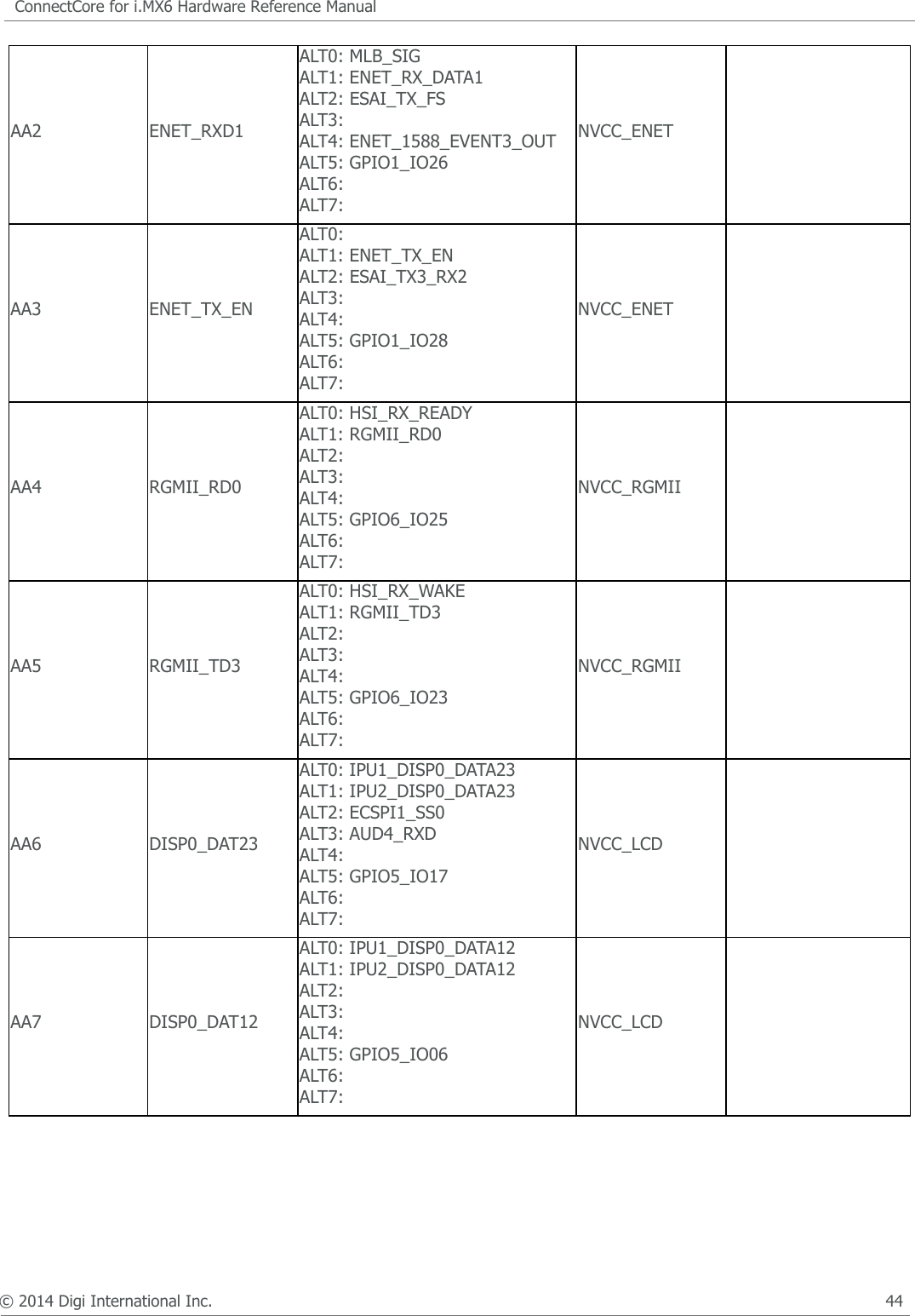
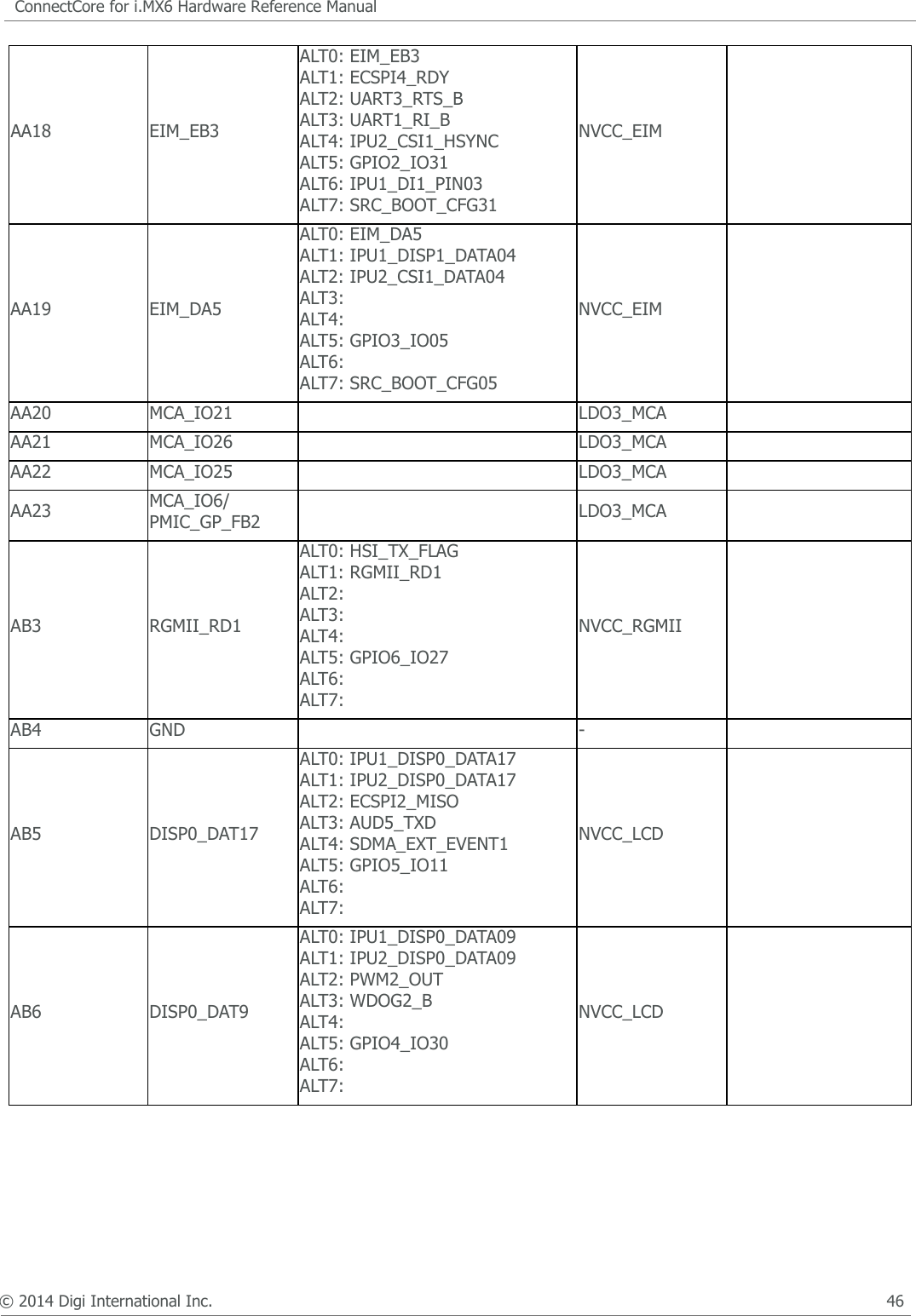
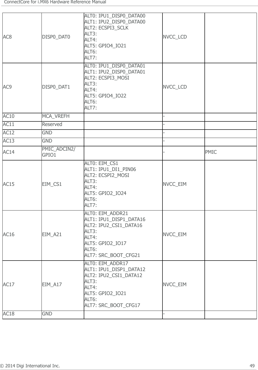
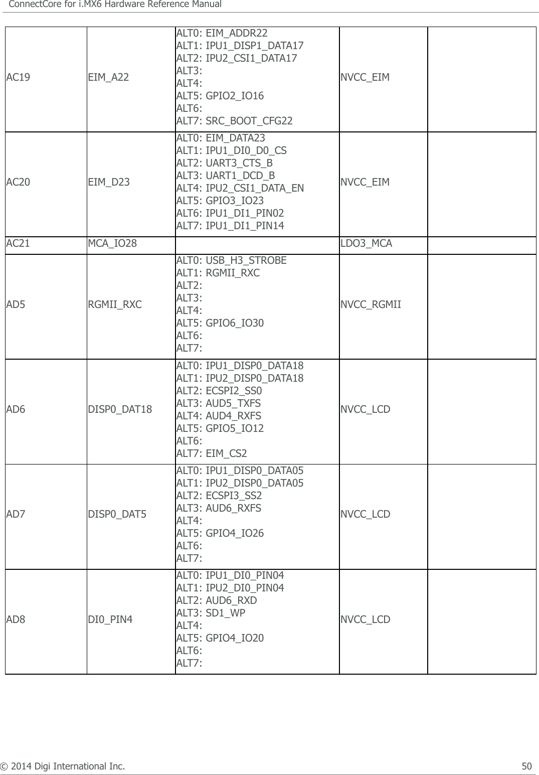
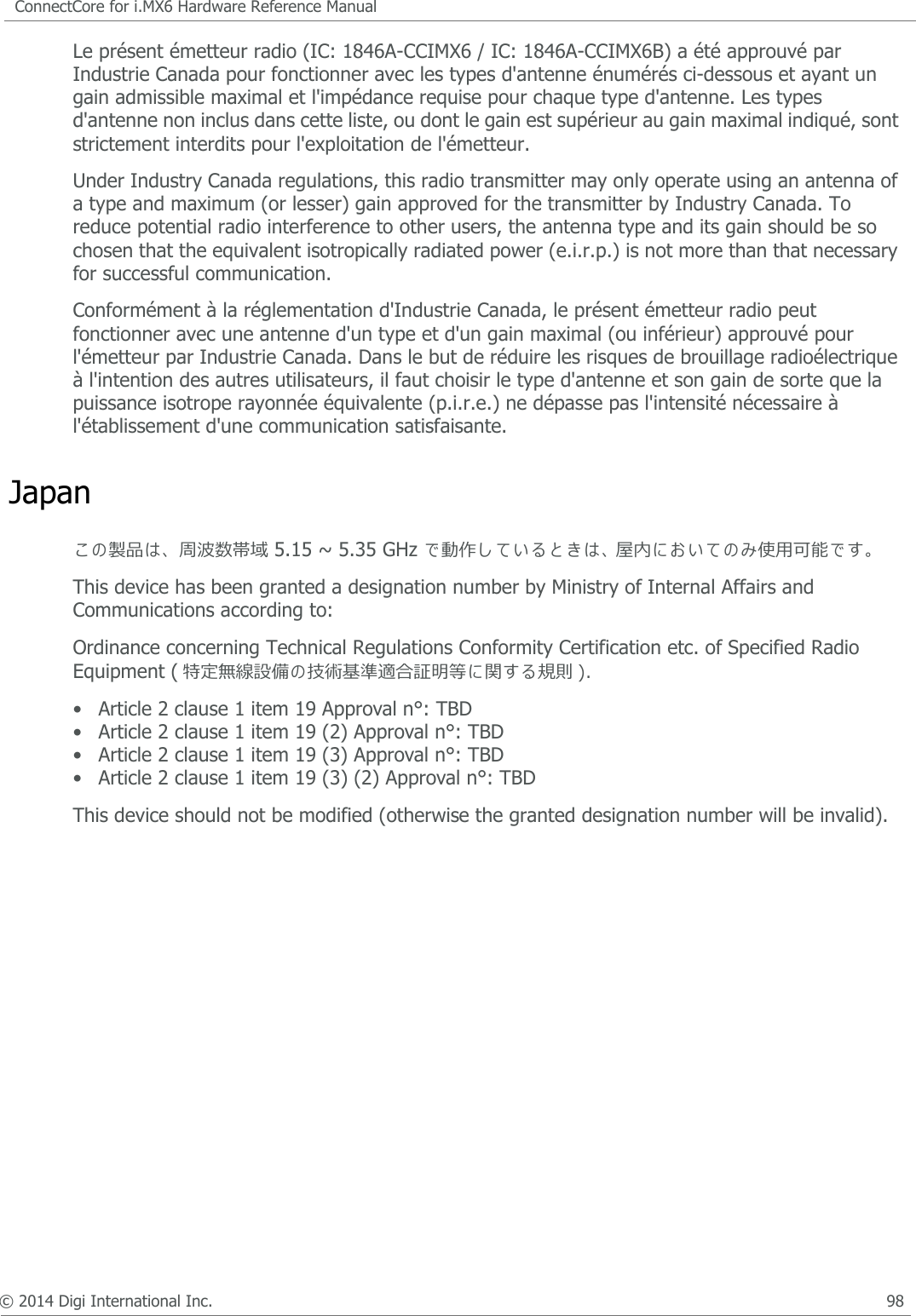
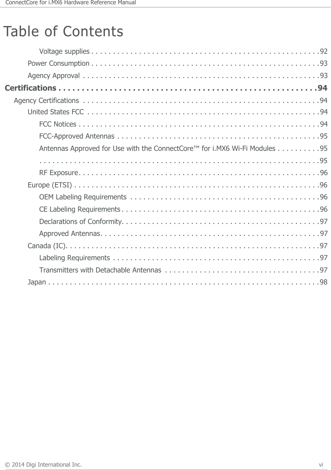
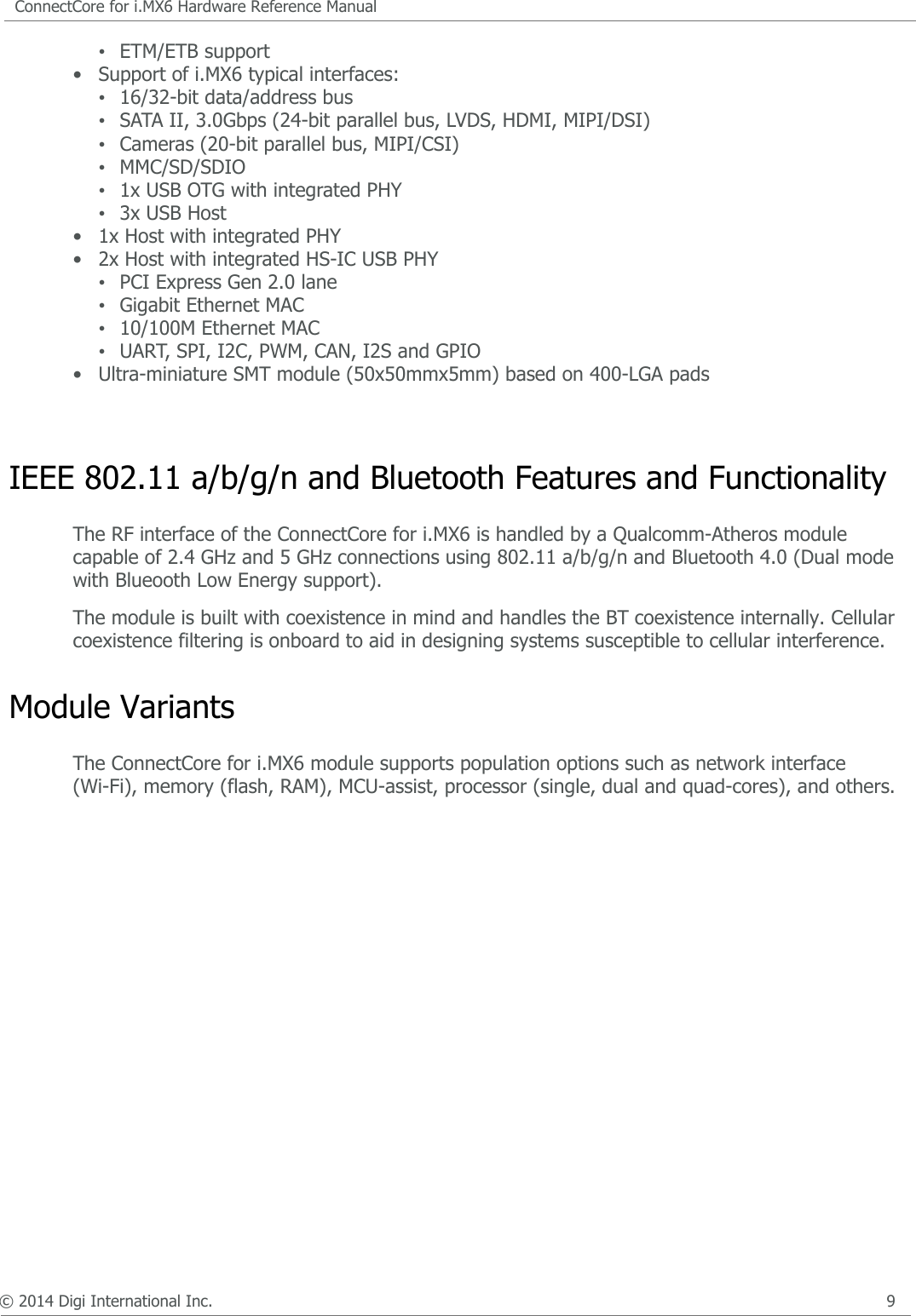
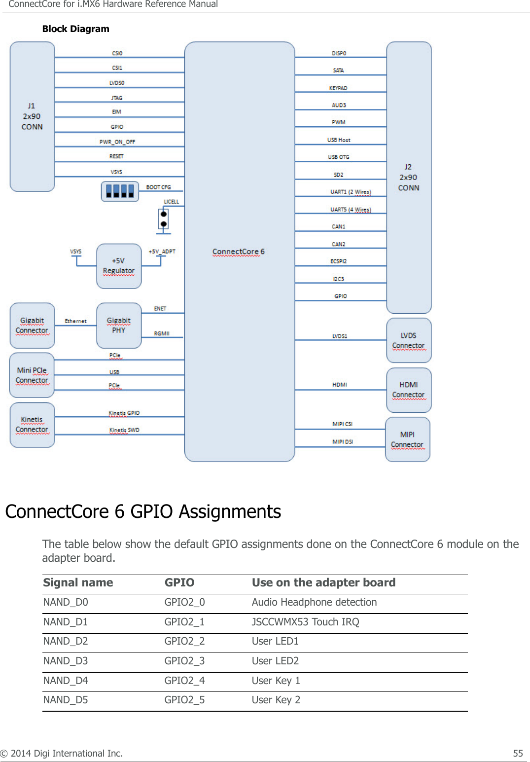
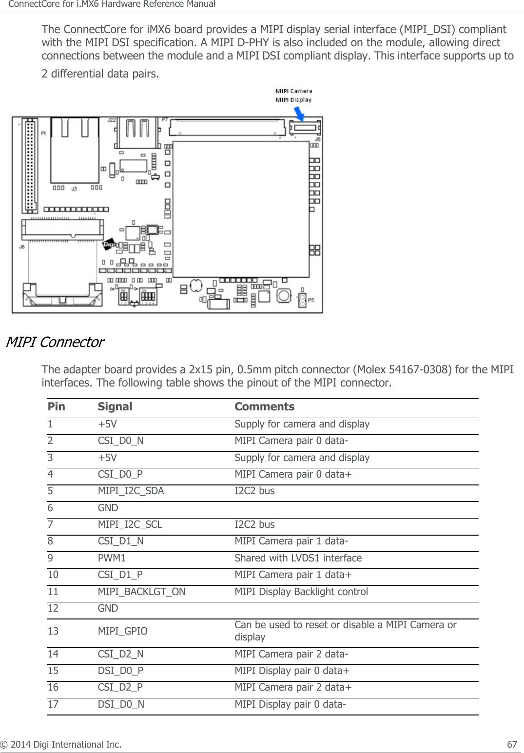
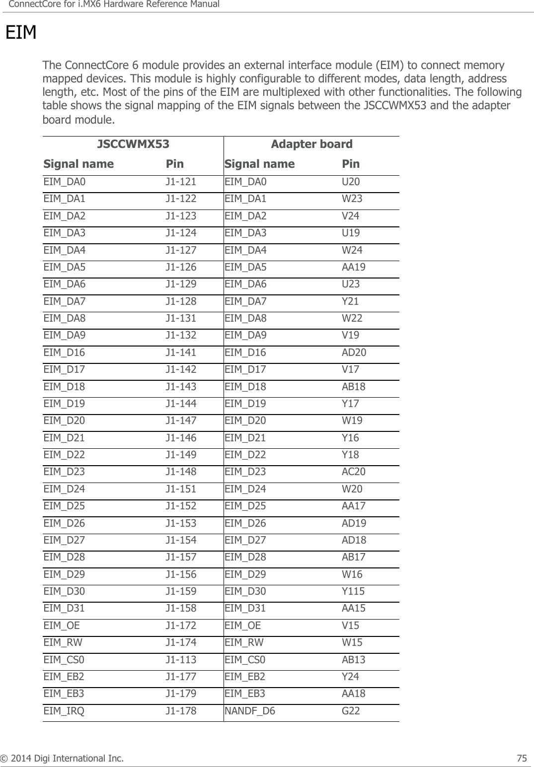
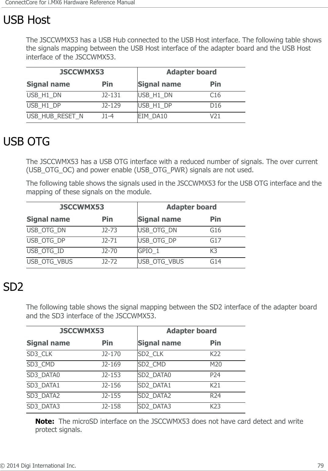
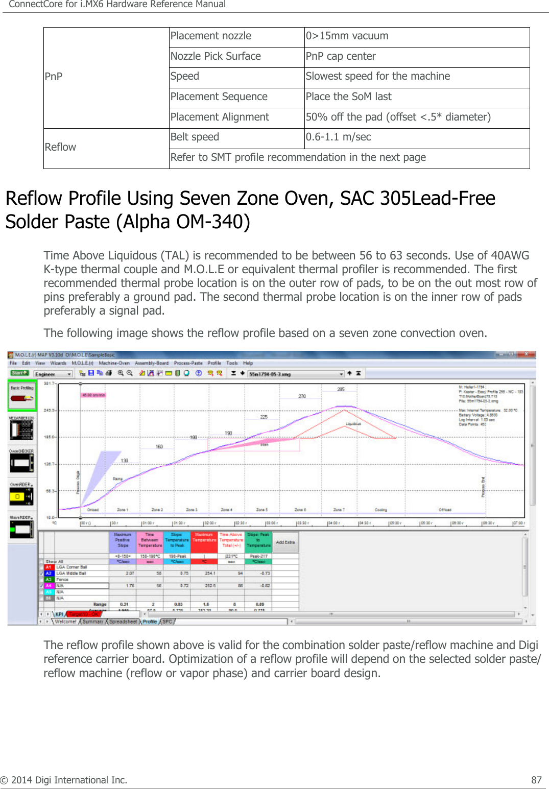
![© 2014 Digi International Inc. 52ConnectCore for i.MX6 Hardware Reference ManualSignal Usage LimitationsThe following signals available on ConnectCore for i.MX6 pads have a limited usage:• SD1_CLK (pad L21), SD1_CMD (pad J23), SD1_DAT[3:0] (pads L20, J21, J22 and N24) are only available externally on modules which don't have Wi-Fi populated.• SD3_DAT4/BT_UART_RXD (pad C22), SD3_DAT5/BT_UART_TXD (pad D23), SD3_CLK/BT_UART_RTS (pad B21), SD3_CMD/BT_UART_CTS (pad E23) are only available externally on modules which don't have Bluetooth populated.• NANDF_CLE/BT_WAKE (pad E22) is only available externally on modules which don't have Bluetooth populated.• I2C2_SCL/KEY_COL3 (pad C3) and I2C2_SDA/KEY_ROW3 (pad F2) are used on the module as I2C signals connected to the PMIC and MCA processor. Using these signals externally should be done with caution, since it could prevent the module from working properly. It is recommended that you use another I2C port for connecting external devices to the ConnectCore i.MX6 module in order to avoid excessive bus load.• NANDF_CS1/#MCA_INT (pad H21), CSI0_DAT11/ECSPI2_SS0 (pad A6), CSI0_DAT8/ECSPI2_SCLK (pad D6), CSI0_DAT10/ECSPI2_MISO (pad K5) and CSI0_DAT9/ECSPI2_MOSI (pad D5) are connected to MCA processor. #MCA_INT is a signal reserved as interrupt between MCA processor and i.MX6 processor. The other signals are a SPI bus shared between i.MX6 and MCA processor. The usage and availability of these signals is depending on the firmware running in the MCA processor.• ON/OFF (pad D18) signal is connected to PMIC and MCA. • #POR (pad E18) is connected to PMIC and i.MX6 processor.AD19 EIM_D26ALT0: EIM_DATA26ALT1: IPU1_DI1_PIN11ALT2: IPU1_CSI0_DATA01ALT3: IPU2_CSI1_DATA14ALT4: UART2_TX_DATAALT5: GPIO3_IO26ALT6: IPU1_SISG2ALT7: IPU1_DISP1_DATA22NVCC_EIM AD20 EIM_D16ALT0: EIM_DATA16ALT1: ECSPI1_SCLKALT2: IPU1_DI0_PIN05ALT3: IPU2_CSI1_DATA18ALT4: HDMI_TX_DDC_SDAALT5: GPIO3_IO16ALT6: I2C2_SDAALT7:NVCC_EIM](https://usermanual.wiki/Digi/CCIMX6/User-Guide-2417064-Page-54.png)
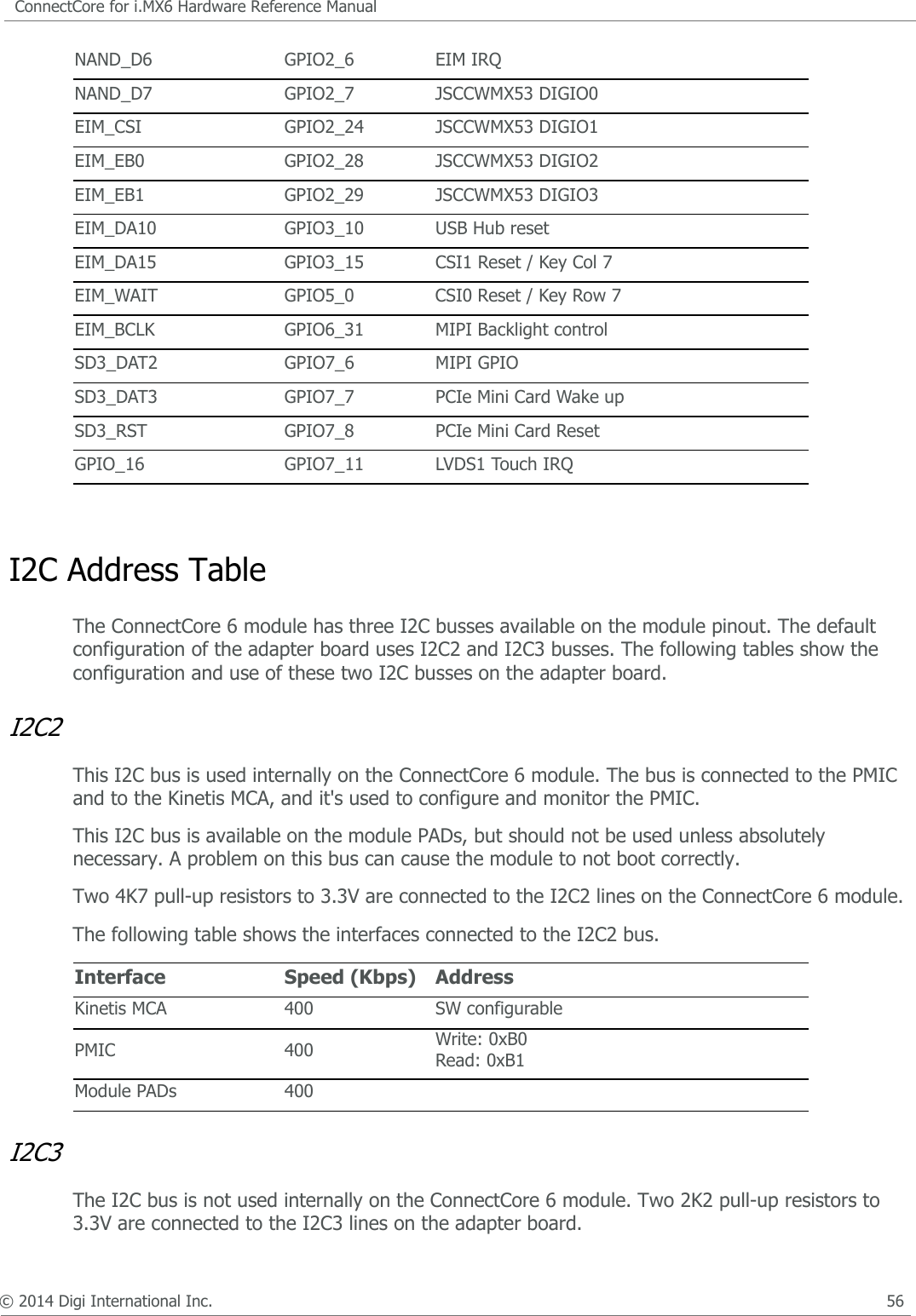
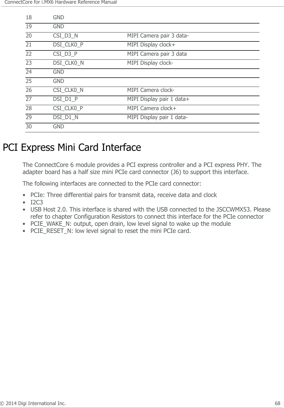
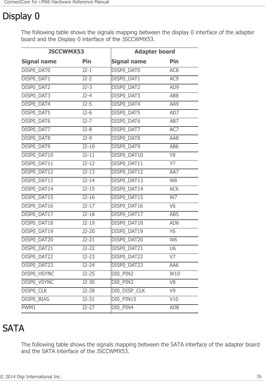
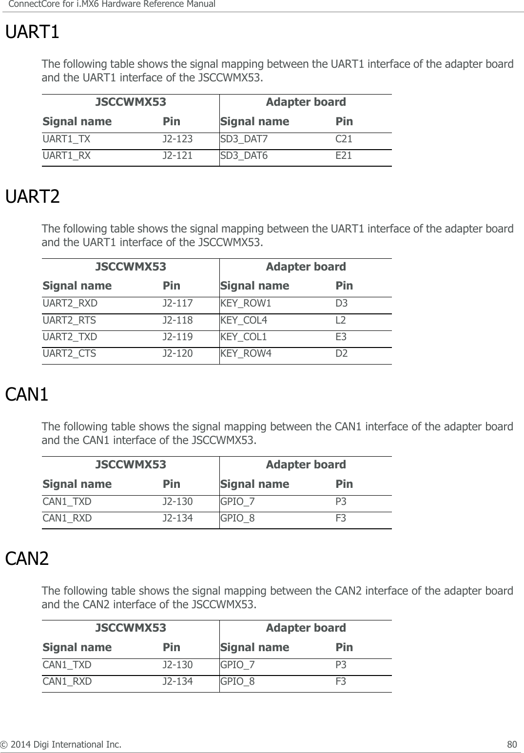
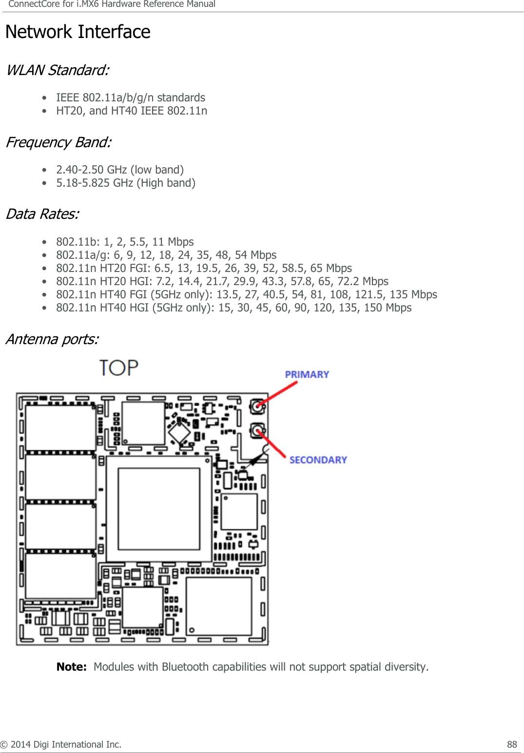
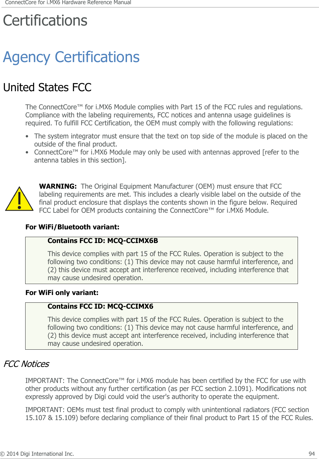
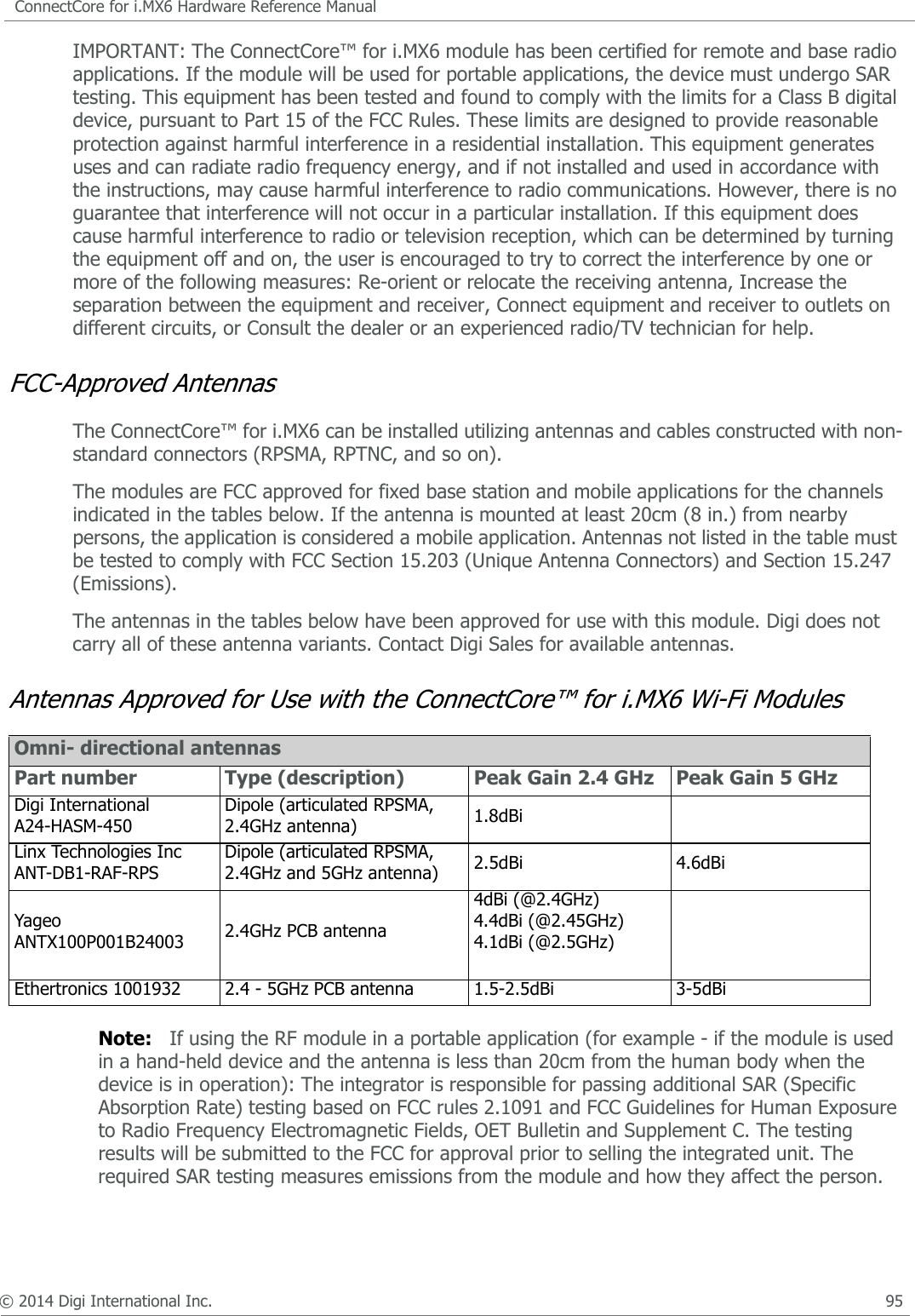
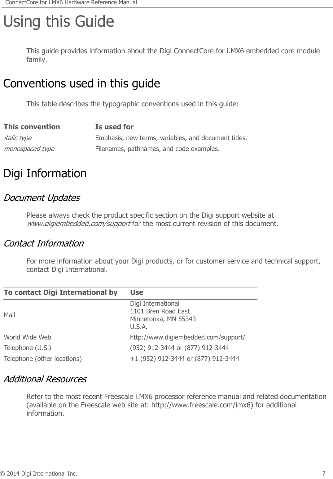
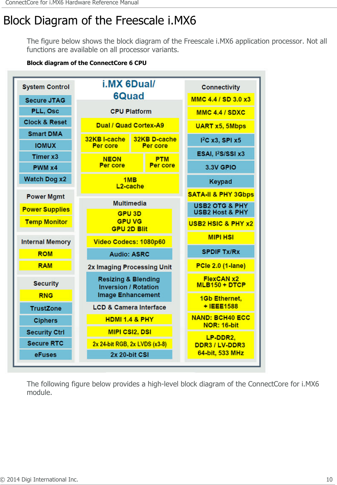
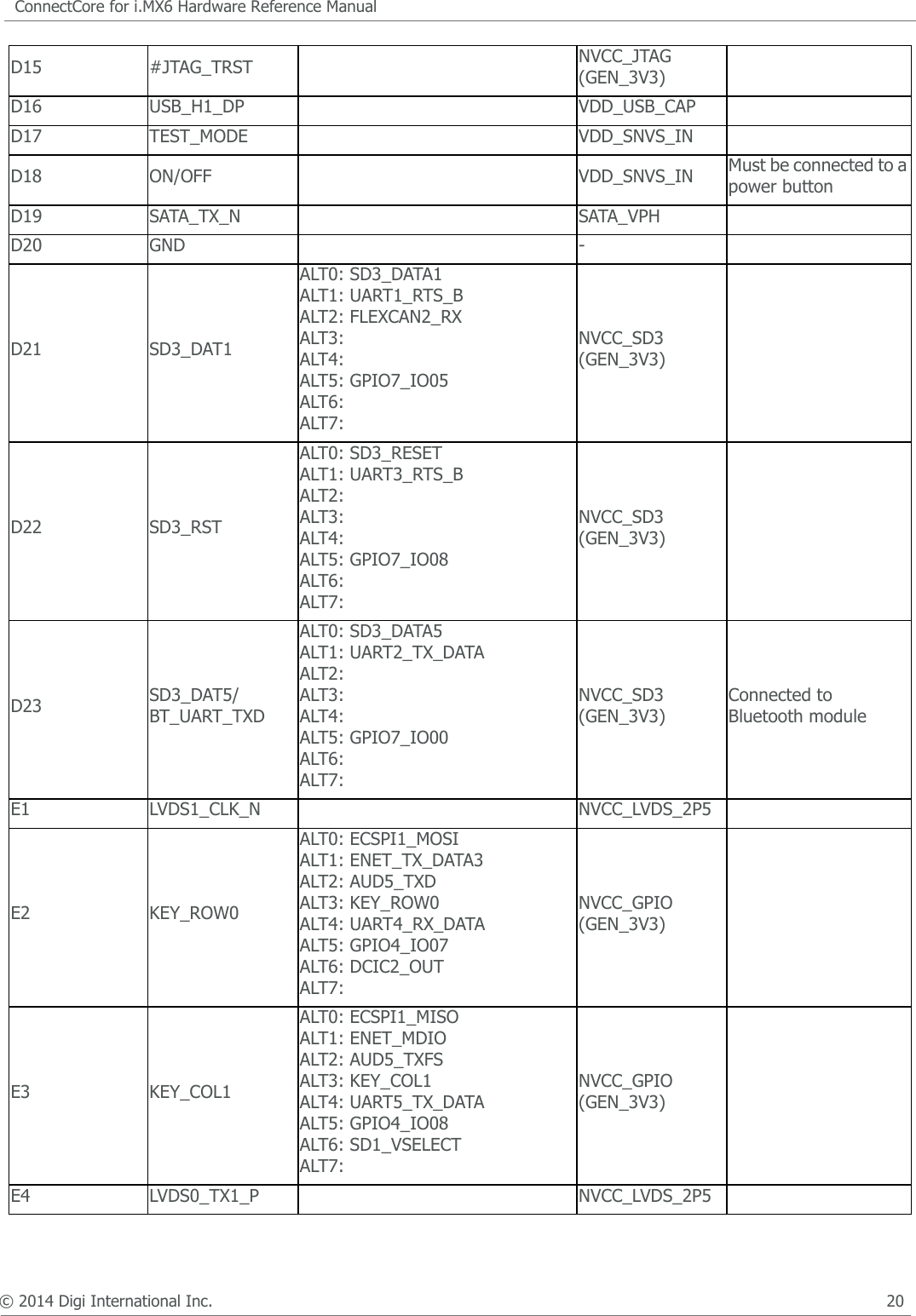
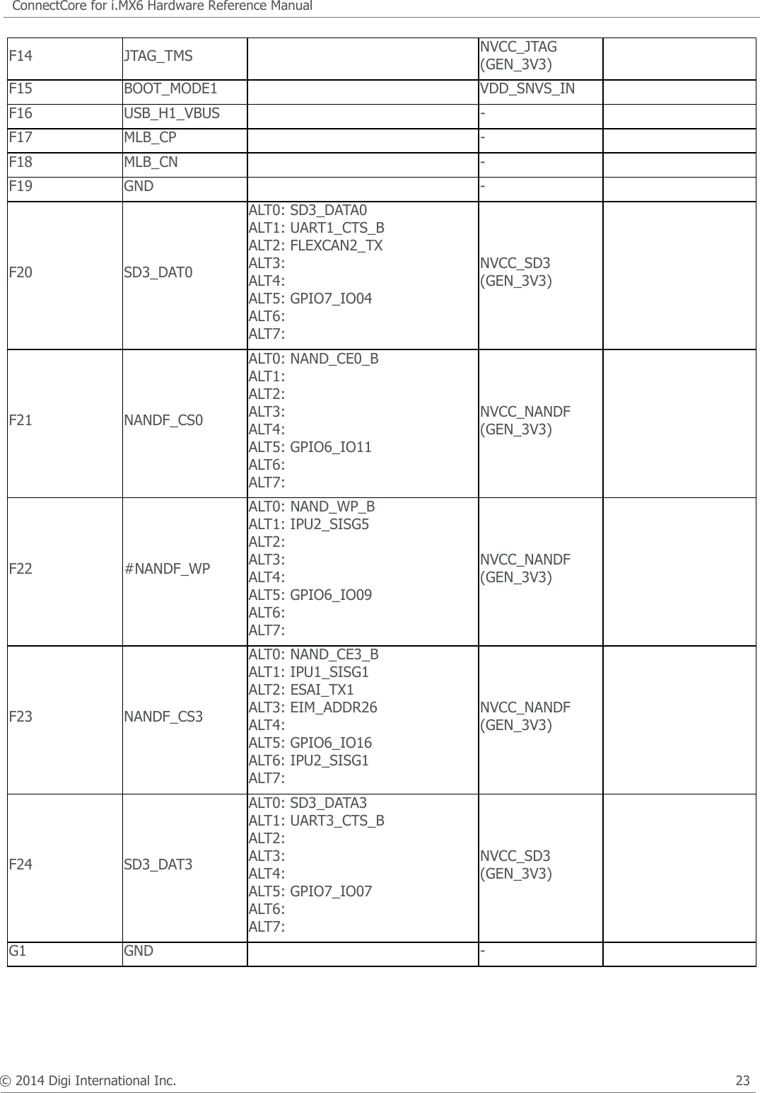
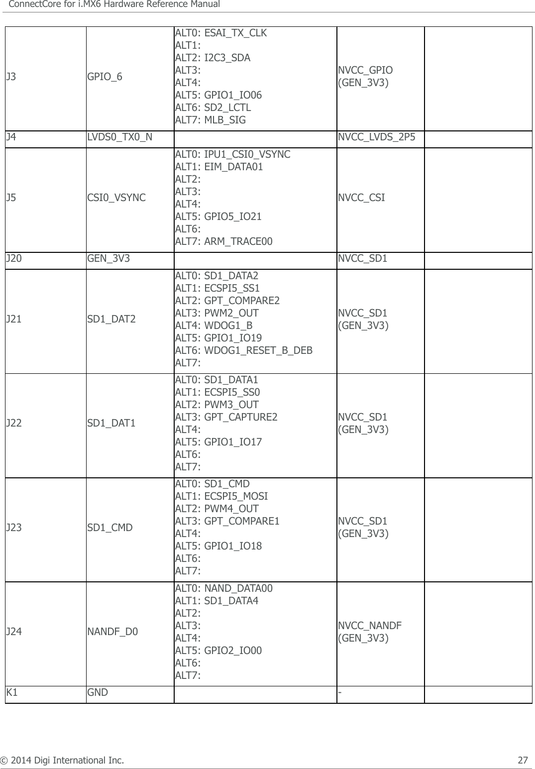
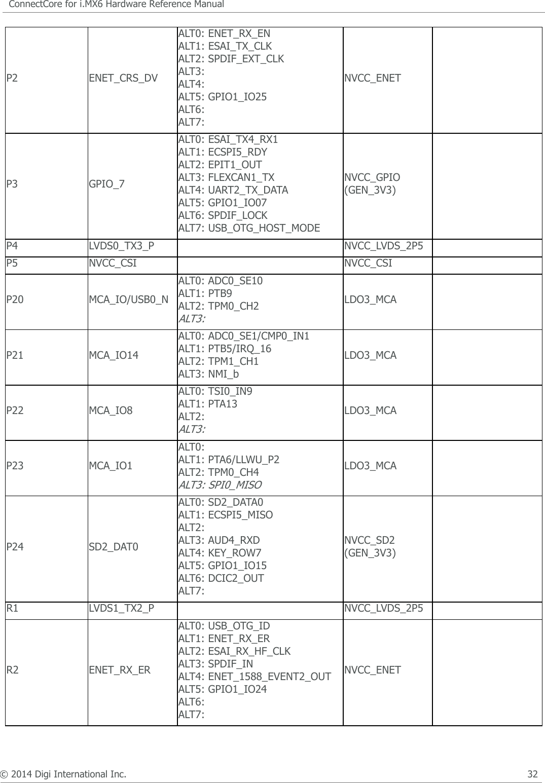
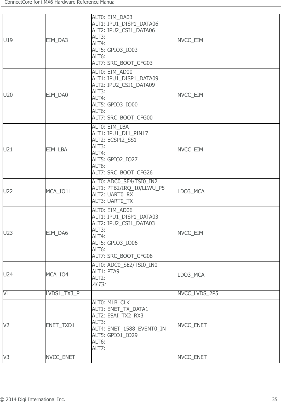
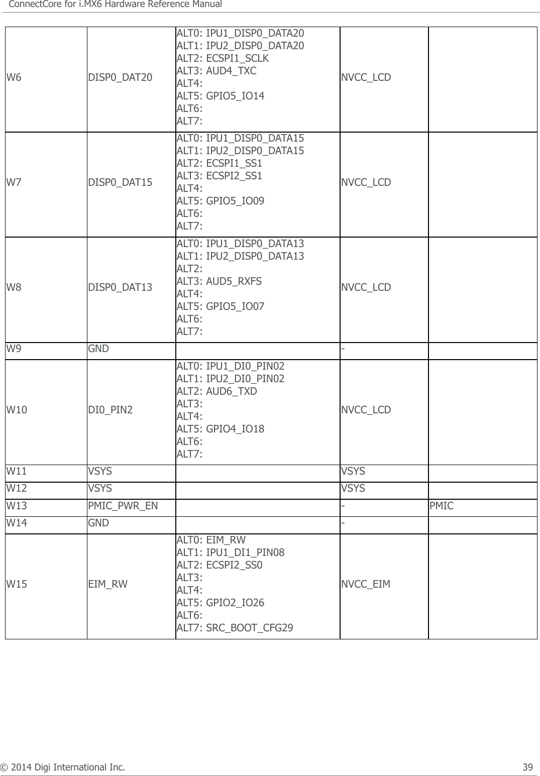
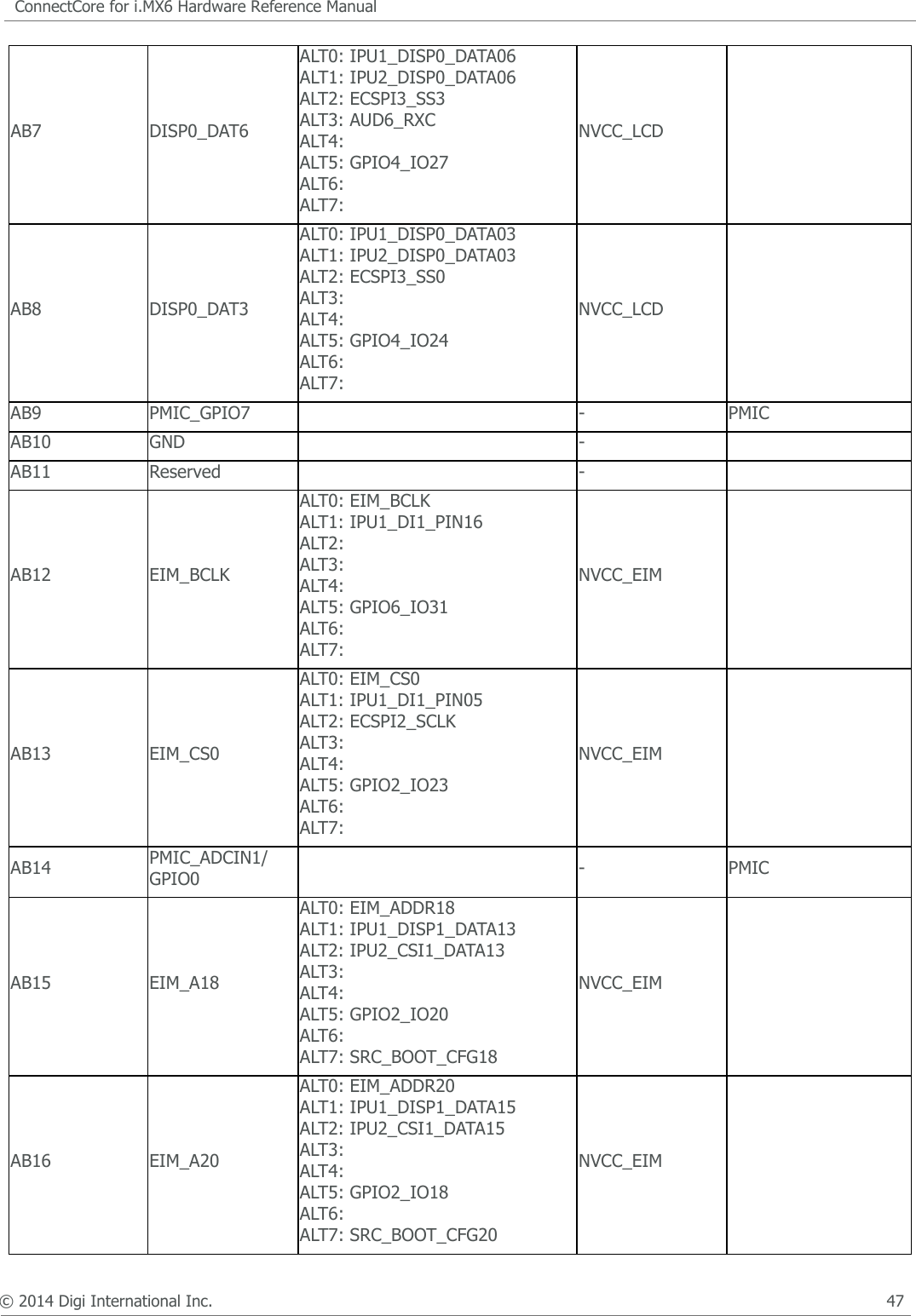
![© 2014 Digi International Inc. 94ConnectCore for i.MX6 Hardware Reference ManualCertificationsAgency CertificationsUnited States FCC The ConnectCore™ for i.MX6 Module complies with Part 15 of the FCC rules and regulations. Compliance with the labeling requirements, FCC notices and antenna usage guidelines is required. To fulfill FCC Certification, the OEM must comply with the following regulations:• The system integrator must ensure that the text on top side of the module is placed on the outside of the final product.• ConnectCore™ for i.MX6 Module may only be used with antennas approved [refer to the antenna tables in this section].For WiFi/Bluetooth variant: For WiFi only variant:FCC NoticesIMPORTANT: The ConnectCore™ for i.MX6 module has been certified by the FCC for use with other products without any further certification (as per FCC section 2.1091). Modifications not expressly approved by Digi could void the user's authority to operate the equipment. IMPORTANT: OEMs must test final product to comply with unintentional radiators (FCC section 15.107 & 15.109) before declaring compliance of their final product to Part 15 of the FCC Rules.WARNING: The Original Equipment Manufacturer (OEM) must ensure that FCC labeling requirements are met. This includes a clearly visible label on the outside of the final product enclosure that displays the contents shown in the figure below. Required FCC Label for OEM products containing the ConnectCore™ for i.MX6 Module.Contains FCC ID: MCQ-CCIMX6BThis device complies with part 15 of the FCC Rules. Operation is subject to the following two conditions: (1) This device may not cause harmful interference, and (2) this device must accept ant interference received, including interference that may cause undesired operation.Contains FCC ID: MCQ-CCIMX6This device complies with part 15 of the FCC Rules. Operation is subject to the following two conditions: (1) This device may not cause harmful interference, and (2) this device must accept ant interference received, including interference that may cause undesired operation.](https://usermanual.wiki/Digi/CCIMX6/User-Guide-2417064-Page-96.png)