Digi CCIMX6UL ConnectCore for i.MX6UL User Manual manual instructions
Digi International Inc ConnectCore for i.MX6UL manual instructions
Digi >
manual_instructions

ConnectCore® 6UL
System-on-module solution
Hardware Reference Manual

Revision history—90001523
Revision Date Description
1P May
2016
Preliminary document
2P May
2016
Add reflow profiles
3P June
2016
Revise bootstrap-GPIO configuration table; add new power supply architecture
graphics; revise MCA pinout table
4P August
2016
Revise pinout table, add new and revise graphics, update official weight, list
Bluetooth 4.2, incorporate miscellaneous editorial corrections, remove
"preliminary" designation
A March
2017
Add power consumption, MCA, wireless interfaces, socket, assembly and
product soldering, cryptoauthentication, bootstrap, and electrical
characteristics sections; modify pinout tables; miscellaneous editorial revisions.
Trademarks and copyright
Digi, Digi International, and the Digi logo are trademarks or registered trademarks in the United
States and other countries worldwide. All other trademarks mentioned in this document are the
property of their respective owners.
© 2016 Digi International Inc. All rights reserved.
Disclaimers
Information in this document is subject to change without notice and does not represent a
commitment on the part of Digi International. Digi provides this document “as is,” without warranty of
any kind, expressed or implied, including, but not limited to, the implied warranties of fitness or
merchantability for a particular purpose. Digi may make improvements and/or changes in this manual
or in the product(s) and/or the program(s) described in this manual at any time.
Warranty
To view product warranty information, go to the following website:
www.digi.com/howtobuy/terms
Send comments
Documentation feedback: To provide feedback on this document, send your comments to
techcomm@digi.com.
ConnectCore® 6UL Hardware Reference Manual 2

ConnectCore® 6UL Hardware Reference Manual 3
Customer support
Digi Technical Support: Digi offers multiple technical support plans and service packages to help our
customers get the most out of their Digi product. For information on Technical Support plans and
pricing, contact us at +1 952.912.3444 or visit us at www.digi.com/support.
Support portal login: www.digi.com/support/eservice

Contents
About the ConnectCore® 6UL
Features and functionality 6
ConnectCore 6UL module variants 8
Block diagrams 8
ConnectCore 6UL module 9
NXP i.MX6UL application processor 10
Power supply 11
Power supply architecture 11
System power-up sequence 14
Bootstrap 15
Boot from fuses 15
Internal boot 16
Serial downloader 17
Wireless interfaces 17
WLAN 802.11a/b/g/n/ac 17
Antenna ports 23
Bluetooth 23
RF control signals 23
Micro Controller Assist™ 23
ConnectCore 6UL module lines related to the MCA 24
Reset control 25
IOs 26
Watchdog 28
Real-time clock 29
Tamper support 29
Power management 30
MCA firmware update 33
CryptoAuthentication device 33
Module pinout - general layout 33
External signals and pin multiplexing 35
Module specifications
Electrical specifications 116
With front-end LDO 116
Without front-end LDO 116
Power consumption 116
Power consumption use cases 117
Global power consumption 119
Power consumption: Wireless power consumption increase 120
Power consumption: Real wireless transmission 121
Power consumption: Wireless-UART bridge 122
Mechanical specifications 122
Dimensions 122
ConnectCore® 6UL Hardware Reference Manual 4

ConnectCore® 6UL Hardware Reference Manual 5
Host PCB footprint 124
Weight 125
Environmental specifications 125
Socket options 125
Assembly instructions
Moisture sensitivity and shelf life 128
Mounting 128
Solder paste print 128
Stencil 128
Coplanarity 128
SMT pick and place 129
SMT process parameter reference - for both castellation and LGA applications 129
Reflow profiles using a ten-zone oven, SAC 305 lead-free solder paste (Alpha OM-340) 129
Vapor Phase Profile Recommendation Using IBL 309 Batch Soldering Machine, SAC 305 Lead-
Free Solder Paste (Alpha OM-340) 130
Vapor Phase IBL 309 batch soldering machine settings 132
Conformal coating 132
Certifications
External antenna 134
United States FCC 134
FCC notices 134
FCC-approved antennas 135
RF exposure 135
Europe 136
OEM labeling requirements 136
CE labeling requirements 136
Declarations of Conformity 136
Approved antennas 136
Canada (IC) 136
Labeling requirements 137
Transmitters with detachable antennas 137
RF exposure 137
Approved antennas 138
Japan 138
Approval Label (MIC Marking) 139

About the ConnectCore® 6UL
The ConnectCore 6UL module delivers a secure and extremely cost-effective connected System-on-
Module platform that is slightly bigger than a postage stamp. Its innovative Digi SMTplus™ (patent-
pending) surface mount form factor allows you to choose simplified design integration leveraging
proven and easy-to-use edge-castellated SMT technology, or a versatile LGA option for ultimate design
flexibility with access to virtually all interfaces.
Built on the NXP i.MX6UL application processor, the module is the intelligent communication engine
for today’s secure connected devices. It seamlessly integrates dual-Ethernet and pre-certified dual-
band Wi-Fi (802.11a/b/g/n/ac) with Bluetooth 4.2 dual mode connectivity.
Features and functionality
The ConnectCore 6UL system-on-module is based on the i.MX6UL processor from NXP. This processor
offers a number of interfaces, most of them multiplexed and not available simultaneously. The module
has the following features:
li.MX6UL single ARMCortex-A7 core operating at speeds up to 528 MHz:
o32 Kb L1 instruction cache
o32 Kb L1 data cache
oUp to 128 KB unified instruction/data L2 cache
oNEONMPE (media processing engine) co-processor
lUp to 1 GB, 16-bit DDR3-800 memory
lUp to 2 GB, 8-bit SLC NAND flash memory
lNXP PF3000 power management IC (PMIC):
ox 4 DC/DC buck converters
ox 6 LDO regulators
ox 1 DC/DC boost converter
oOTP (one-time programmable) memory
oCoin cell charger and always-ON RTC supply
lGraphical hardware accelerators:
oPXP (PiXel Processing Pipeline)
oASRC (asynchronous sample rate converter)
lSecure Element
lSecurity accelerators:
ConnectCore® 6UL Hardware Reference Manual 6

About the ConnectCore® 6UL Features and functionality
ConnectCore® 6UL Hardware Reference Manual 7
oARMTrustZone
oCAAM (cryptographic acceleration and assurance module)
oSNVS (secure non-volatile storage)
oCSU (central security unit)
oA-HABv4 (advanced high-assurance boot)
lIEEE 802.11 a/b/g/n/ac WLAN interface
lBluetoothversion 4.2 dual-mode
lARM Cortex-M0+ Micro Controller Assist™ (MCA) subsystem
lDebug interfaces:
oSystem JTAG controller
oSingle Wired Debug (SWD) interface for the MCA
lSupport of i.MX6UL interfaces:
o16-bit data/address bus
oDisplay: 24-bit parallel bus
oCamera: 24-bit parallel bus
oKPP (key pad port)
oTSC (touch screen controller)
ox 2 MMC/SD/SDIO card ports
ox 2 USB 2.0 OTG with integrated HS USB PHYs
ox 2 10/100 Mbps Ethernet MAC
oUART, SPI, I2C, PWM, ADC, CAN, I2S, and GPIOs
lUltra-miniature SMT module (29 x 29 x 3.5 mm) based on 245 pads (245 LGA, 76 also available as
castellated pads)

About the ConnectCore® 6UL ConnectCore 6UL module variants
ConnectCore® 6UL Hardware Reference Manual 8
ConnectCore 6UL module variants
Smart
part
number
Part
number
ConnectCore
6UL SOM
variant Description CPU1
DDR3/Bus
-width2WiFi/Bluetooth
CC-
WMX-
JN58-
NE
50001939-
01
0x02 ConnectCore for
i.MX6UL-2, 528
MHz, Industrial
Temp, 256 MB SLC
NAND, 256 MB
DDR3, Dual 10/100
Ethernet,
802.11a/b/g/n/ac,
Bluetooth 4.1,
ANT+
G2CVK05 -
40/+105°C
528 MHz
256MiB
(1x2Gbit)
/ 16bit, -
40/+95ºC
CC-MX-
JN58-Z1
50001939-
02
0x03 ConnectCore for
i.MX6UL-2, 528
MHz, Industrial
Temp, 256 MB SLC
NAND, 256 MB
DDR3, Dual 10/100
Ethernet
G2CVK05 -
40/+105°C
528 MHz
256MiB
(1x2Gbit)
/ 16bit, -
40/+95ºC
1CPU temperature is Tj (junction)
2DDR3 temperature is Ta (ambient)
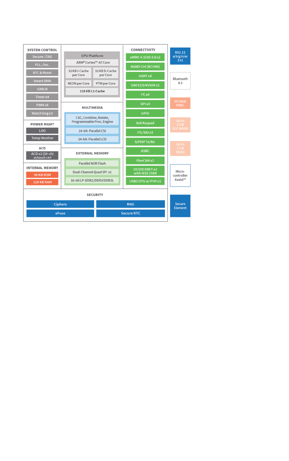
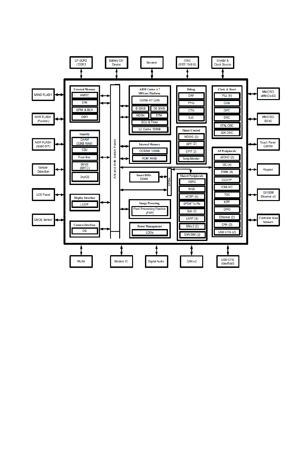
Block diagrams
The figures below show block diagrams of the ConnectCore 6UL module and of the NXP i.MX6UL
application processor.
About the ConnectCore® 6UL Block diagrams
ConnectCore® 6UL Hardware Reference Manual 9
ConnectCore 6UL module
About the ConnectCore® 6UL Block diagrams
ConnectCore® 6UL Hardware Reference Manual 10
NXP i.MX6UL application processor
About the ConnectCore® 6UL Power supply
ConnectCore® 6UL Hardware Reference Manual 11
Power supply
Power supply architecture
The ConnectCore 6UL requires a primary power supply input. This supply is the main power domain to
the on-module NXP PF3000 power management IC (PMIC), which generates all required supply
voltages for the module as well as the external interfaces. The system can be powered from voltages
up to 5.5V. See Powering the system from a nominal 5V power supply (4.5V to 5.5V) and Powering the
system for battery-powered applications (3.7V - 4.5V) for recommended power schemes for the
ConnectCore 6UL module.
The ConnectCore 6UL module has a dedicated pin for connecting a coin cell backup battery or super
capacitor. You can enable a coin cell charger on the PMIC with Li-ion rechargeable batteries. This
backup battery or super capacitor is mandatory if RTC time must persist after the module has been
disconnected from main power. You must also follow the recommended diode configuration as shown
in the diagrams below to make sure the module holds the system time.
If RTC time retention is not required, you can remove the circuitry from your design and connect the
3.3V voltage regulator directly to the VCC_MCA and MCA_VIN_DET pins.
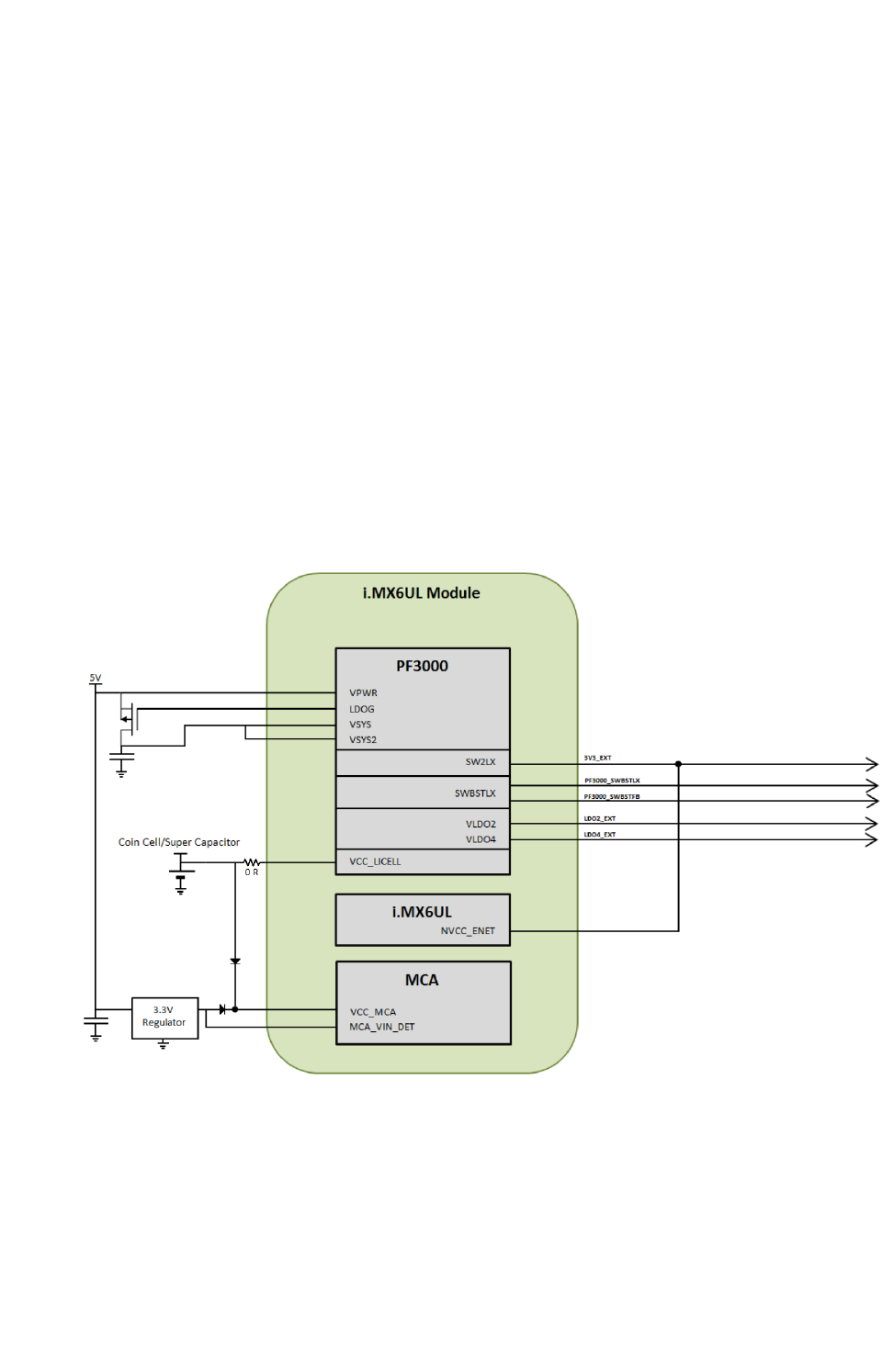
Powering the system from a nominal 5V power supply (4.5V to 5.5V)
About the ConnectCore® 6UL Power supply
ConnectCore® 6UL Hardware Reference Manual 12
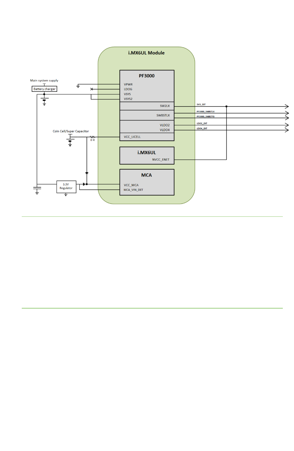
Powering the system for battery-powered applications (3.7V - 4.5V)
Note In the implementations shown above, the coin cell/supercapacitor is connected to VCC_LICELL
pin of the ConnectCore 6UL module, allowing coin-cell charger applications. This VCC_LICELL
connection feeds the VSNVS regulator of the PMIC, which supplies the SNVS power domain of the
CPU. This power domain allows some functionality of the CPU in low power mode applications when
the main power supply of the system is removed. However, this connection significantly increases the
power consumption of the coin cell/supercapacitor in this low-power mode.
To optimize power management in coin cell applications:
Do not connect the coin cell/supercapacitor to the VCC_LICELL power domain (keep the connection to
VCC_MCA). This removes coin-cell charger functionality but drastically reduces power consumption
and extends the life of the power supply. However, this connection significantly increases the power
consumption of the coin cell/supercapacitor in this low-power mode to around 350 uA.
The power architecture of the module is described in more detail below.
The PMIC generates the following power domains that are available on the module pads:
nBuck converters. Two buck regulators provide 3.3V:
lSW1A: 3V3_INT, powers several interfaces inside the module
lSW2: 3V3_EXT, free power line not used inside the module
nAnd another two buck regulators used for internal supply:
lSW1B: VDD_ARM_SOC_IN
lSW3: VCC_DDR3
About the ConnectCore® 6UL Power supply
ConnectCore® 6UL Hardware Reference Manual 13
Power
domain Regulator
type
Output
accuracy
Maximum
current
Dropout
voltage
(MAX)
Turn on
time
(MAX)
Turn off
time
(MAX)
Quiescent
current in OFF
mode (TYP)
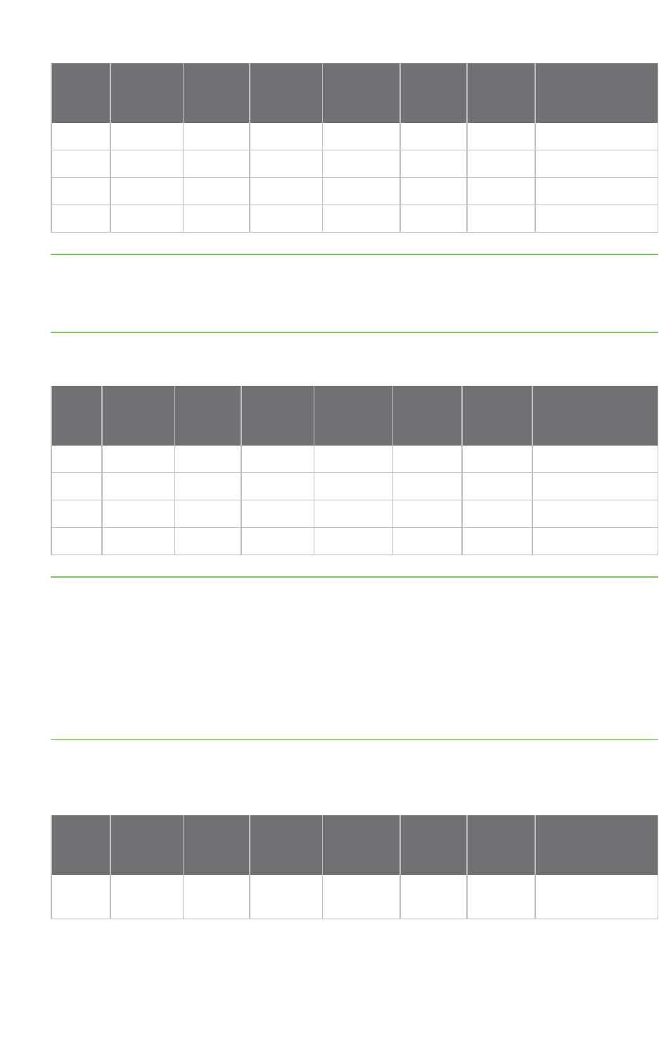
SW1A DC/DC +/-6.0 % 1.00 A - 500 us - -
SW2 DC/DC +/-6.0 % 1.25 A - 500 us - -
SW1B DC/DC +/-6.0 % 1.75 A - 500 us - -
SW3 DC/DC +/-6.0 % 1.5 A - 500 us - -
Note Maximum current includes both the module and the module carrier board consumption.
SW1: parameters specified at TA=-40 °C to 85 °C, VIN=VSW1xIN=3.6V, VSW1x=1.2 V, ISW1x=100 mA.
SW2: parameters specified at TA=-40 °C to 85 °C, VIN=VSW2IN=3.6V, VSW2=3.15 V, ISW2=100 mA.
SW3: parameters specified at TA=-40 °C to 85 °C, VIN=VSW3IN=3.6V, VSW3=1.5 V, ISW3=100 mA.
nLDO regulators. Four PMIC regulators are available; the module uses LDO1: VDDA_ADC_3P3.
LDO
Regulator
type
Output
accuracy
Maximum
current
Dropout
voltage
(MAX)
Turn on
time
(MAX)
Turn off
time
(MAX)
Quiescent current
in OFF mode
(TYP)
VLDO1 1.8-3.3V +/-3.0 % 0.100 A 60 mV 500 us 10 ms 13 uA
VLDO2 0.8-1.55V +/-3.0 % 0.250 A 60 mV 500 us 10 ms 13 uA
VLDO3 1.8-3.3V +/-3.0 % 0.100 A 60 mV 500 us 10 ms 13 uA
VLDO4 1.8-3.3V +/-3.0 % 0.350 A 60 mV 500 us 10 ms 13 uA
Note Maximum current includes both the module and the module carrier board consumption.
VLDO1 parameters specified at TA=-40 °C to 85 °C, VIN=3.6V, VLDO1IN=3.6V, VLDO1=3.3V, ILDO1=10
mA.
VLDO2 parameters specified at TA=-40 °C to 85 °C, VIN=3.6V, VLDO2IN=3.0V, VLDO2=1.55V, ILDO2=10
mA.
VLDO3 parameters specified at TA=-40 °C to 85 °C, VIN=3.6V, VLDO34IN=3.6V, VLDO3=3.3V, ILDO3=10
mA.
VLDO4 parameters specified at TA=-40 °C to 85 °C, VIN=3.6V, VLDO34IN=3.6V, VLDO4=3.3V, ILDO4=10
mA.
nBoost converter. The PMIC offers a boost regulator that is not used inside the module but that
is available in the pinout of the LGA version for customizations.
Power
domain
Regulator
type
Output
accuracy
Maximum
current
Dropout
voltage
(MAX)
Turn on
time
(MAX)
Turn off
time
(MAX)
Quiescent
current in OFF
mode (TYP)
SWBST DC/DC -4.0% /
+3%
0.6 A - 2 ms - -
About the ConnectCore® 6UL Power supply
ConnectCore® 6UL Hardware Reference Manual 14
Note SWBST parameters specified at TA=-40 °C to 85 °C, VIN=VSWBSTIN=3.6V, VLSWBST=5.0V,
ISWBST=100 mA.
VSYS and VSYS2 are the supply inputs to the regulators and buck converters of the PMIC. Both inputs
are available on the module pads and can be connected to a single voltage input or to two different
voltages on systems that require high efficiency on the power system:
nVSYS powers SW1A, SW2, LDO1 and LDO34 (shared input for LDO3 and LDO4).
nVSYS2 powers SW1B, SW3 and LDO2.
The power management IC located on the module is responsible for generating all required i.MX6UL
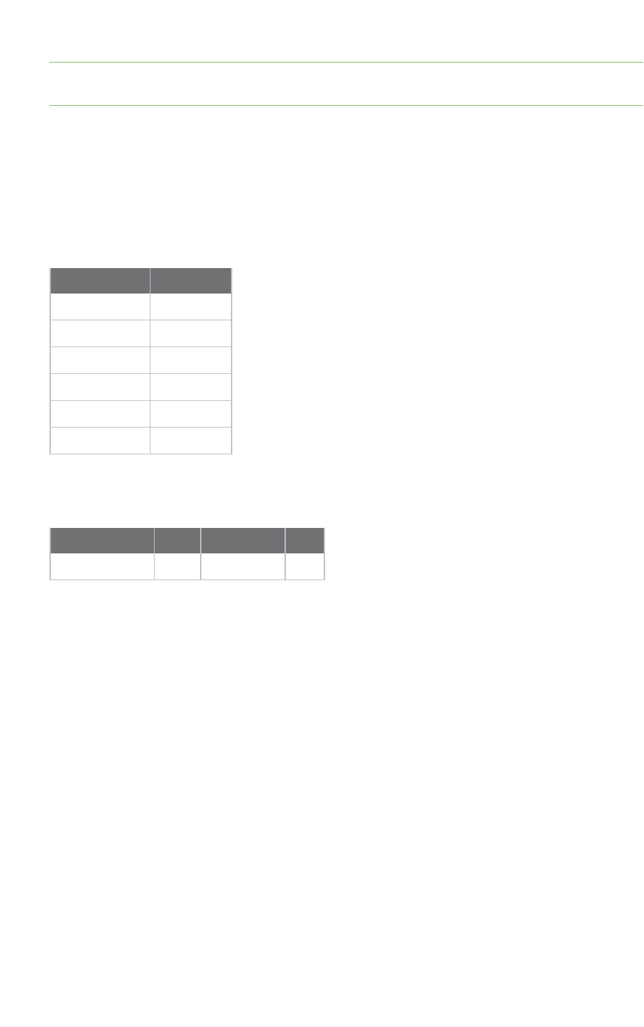
processor supplies. Some of the I/O supplies are set on the module. See the following table:
Power domain Connection
NVCC_NAND 3V3_INT
NVCC_GPIO 3V3_INT
NVCC_SD1 3V3_INT
NVCC_UART 3V3_INT
NVCC_CSI 3V3_INT
NVCC_LCD 3V3_INT
One I/O voltage must be set externally and is left unconnected on the ConnectCore 6UL module:
NVCC_ENET. See the following table for operating range of NVCC_ENET:
Power domain Min Type Max
NVCC_ENET 1.65 V 1.8/2.8/3.3 V 3.6 V
As shown in the table above, the supply has a wide operating range. In order to provide the most cost-
effective and flexible solution for a given use case, the supplies listed in the table must be provided by
the carrier board integrating the ConnectCore 6UL module. However, PMIC 3.3V and LDO power rails
are dedicated power sources for supplying i.MX6UL power domains.
For more information related to the PMIC power-up strategy, refer to section 6.3.5 of the NXP PF3000
datasheet.
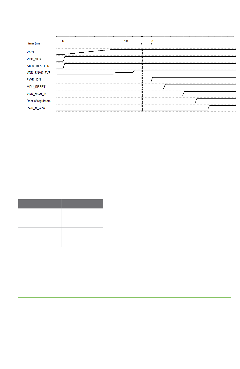
System power-up sequence
When the power supply is connected to the ConnectCore 6UL module, the PMIC and the MCA are the
first components to be powered up. VIN is the PMIC input power line, while VCC_MCA is the MCA input
line. The MCA starts to run as soon as it is powered up, but the PMIC follows a fixed initialization
process (see the NXP PF3000 Datasheet for a full description). In this initialization, the first regulator
to automatically be powered on is the VDD_SNVS_3V3. Once this regulator is up, the PMIC can be
switched on by controlling the PWRON pin (the on-off control line of the PMIC). This pin is controlled by
the MCA. The MCA will turn on the PMIC after a user-programmable delay (by default 50 ms).
Once the PMIC is switched on, another fixed initialization process starts and the PMIC regulators are
turned on following a defined sequence. Finally the CPU reset line (POR_B_CPU), which is also
controlled by the MCA, is released.
About the ConnectCore® 6UL Bootstrap
ConnectCore® 6UL Hardware Reference Manual 15
The following time diagram shows the power-up sequence.
Bootstrap
The ConnectCore 6UL module can be configured to boot from different devices and interfaces as
determined by the Boot ROM. The configuration of the booting process of the CPU is done through:
nBOOT_MODE register, which selects the boot mode of the processor.
neFUSEs and/or GPIOs, which determine the boot configuration.
Four boot modes are available on the i.MX6UL processor. Selection between them is done through
BOOT_MODE[1:0] bits. The bits are externally configurable on two processor IOs, whose values are
latched during boot-up:
BOOT_MODE [1:0] Boot type
00 Boot from fuses
01 Serial downloader
10 Internal boot
11 Reserved
BOOT_MODE[0] and BOOT_MODE[1] are available on dedicated LGA pads on the module. However, on
the castellated pads only BOOT_MODE[1] is available.
Note BOOT_MODE[0] is set to 0 internally on the module through a 100K pull-down resistor. This
means that in applications using only the castellated pads of the module, the only boot modes
available are Boot from fuses and Internal boot. However, once Uboot is running, you can select a
different boot mode (like serial downloader).
Boot from fuses
Boot from fuses is the recommended boot mode for production purposes. When this boot mode is
selected, you must configure several parameters in order to select and configure the boot device of

About the ConnectCore® 6UL Internal boot
ConnectCore® 6UL Hardware Reference Manual 16
the system. These parameters are configured through fuses, which are burned in order to set their
values. This means that the configuration is irreversible.
BOOT_CFG1 selects the boot device through BOOT_CFG1[7:4] bits:
BOOT_CFG1[7:4] Boot device
0000 NOR/OneNAND (EIM)
0001 QSPI
0011 Serial ROM (SPI)
010x SD/eSD/SDXC
011x MMC/eMMC
1xxx Raw NAND
There are many other registers that configure the different boot devices. For a complete description
of the booting configuration, refer to the NXP i.MX 6UltraLite Applications Processor Reference
Manual (Chapter 8: System Boot).
Internal boot
Internal boot is the recommended boot mode for development purposes. When this boot mode is
selected, the selection and configuration of the booting process is done through the same registers
used when booting from fuses. However, this time the values of some registers are overridden using
multiple GPIOs, which are latched during power-up.
The following configuration is done internally in the ConnectCore 6UL module in order to enable
booting from the NAND memory:
Bootstrap configuration Corresponding GPIO Default configuration
BOOT_CFG2[1] LCD_DATA9 100K pull-down
BOOT_CFG2[2] LCD_DATA10 100K pull-down
BOOT_CFG2[3] LCD_DATA11 100K pull-up
BOOT_CFG2[4] LCD_DATA12 100K pull-down
BOOT_CFG2[5] LCD_DATA13 100K pull-up
BOOT_CFG2[6] LCD_DATA14 100K pull-down
BOOT_CFG2[7] LCD_DATA15 100K pull-down
You must also set up BOOT_CFG1[7:0] register when booting from the internal on-module NAND when
Internal boot mode is selected. It must be configured externally (outside the module) as shown in the
following table:

About the ConnectCore® 6UL Serial downloader
ConnectCore® 6UL Hardware Reference Manual 17
Bootstrap configuration Corresponding GPIO Configuration
BOOT_CFG1[0] LCD_DATA0 0
BOOT_CFG1[1] LCD_DATA1 0
BOOT_CFG1[2] LCD_DATA2 0
BOOT_CFG1[3] LCD_DATA3 0
BOOT_CFG1[4] LCD_DATA4 1
BOOT_CFG1[5] LCD_DATA5 0
BOOT_CFG1[6] LCD_DATA6 0
BOOT_CFG1[7] LCD_DATA7 1
Digi recommends you use 10K pull-up and pull-down resistors to configure each line.
The BOOT_CFG1 and BOOT_CFG2 register lines are not dedicated lines of the CPU. This means that
the values of these lines are latched during the power-up, but have a different functionality once the
system is up and running. In this case, these lines belong to the LCD interface. In order to protect the
value of these registers while the system is booting, Digi recommends you use a protection circuitry
as shown in sheet 3 of 7, "Boot selection," of the ConnectCore 6UL reference designs. See
ConnectCore 6UL design files.
Serial downloader
You can use the serial downloader boot mode for device recovery. The serial downloader allows you to
download a program image to the chip through a USB or UART serial connection. When any of the
standard boot modes is selected but the booting process doesn’t succeed (for instance due to wrong
booting device or corrupted images) the CPU automatically jumps to the serial downloader boot
mode.
Wireless interfaces
The ConnectCore 6UL system-on-module combines a wireless local area network (WLAN) and
Bluetooth (BT) dual solution to support IEEE802.11 a/b/g/n/ac WLAN standards and BT 4.2 enabling
seamless integration of WLAN/BT and Low Energy technology. Digi also offers a non-wireless variant of
the ConnectCore 6UL module.
The following sections include specifications for the wireless interfaces available on the ConnectCore
6UL module.
WLAN 802.11a/b/g/n/ac
The 2.4 GHz band on the ConnectCore 6UL module supports 20/40 MHz bandwidths, and the 5 GHz
band supports 20/40/80 MHz bandwidths.
The following sections specify the performance of the WLAN IEEE 802.11a/b/g/n/ac interface on the
ConnectCore 6UL module.

About the ConnectCore® 6UL Wireless interfaces
ConnectCore® 6UL Hardware Reference Manual 18
Modulation and data rates
The following tables list modulation values for ConnectCore 6UL module supports the following WLAN
standards.
Mode Modulation & coding Rate
802.11b DBPSK 1 Mbps
DQPSK 2 Mbps
CCK 5.5 Mbps
CCK 11 Mbps
802.11ga BPSK-1/2 6 Mbps
BPSK-3/4 9 Mbps
QPSK-1/2 12 Mbps
QPSK-3/4 18 Mbps
16QAM-1/2 24 Mbps
16QAM-3/4 36 Mbps
64QAM-2/3 48 Mbps
64QAM-3/4 54 Mbps
802.11n BPSK-1/2 MCS0
QPSK-1/2 MCS1
QPSK-3/4 MCS2
16QAM-1/2 MCS3
16QAM-3/4 MCS4
64QAM-2/3 MCS5
64QAM-3/4 MCS6
64QAM-5/6 MCS7
About the ConnectCore® 6UL Wireless interfaces
ConnectCore® 6UL Hardware Reference Manual 19
Mode Modulation & coding Rate
802.11ac BPSK-1/2 MCS0
QPSK-1/2 MCS1
QPSK-3/4 MCS2
16QAM-1/2 MCS3
16QAM-3/4 MCS4
64QAM-2/3 MCS5
64QAM-3/4 MCS6
64QAM-5/6 MCS7
256QAM-3/4 MCS8
256QAM-5/6 MCS9
Note Rates MCS8 & MCS9 are only available in receive mode.
Data rate (Mbps) - Non Short Guard Interval (Non-SGI)
Data rate
(Mbps) 802.11b 802.11ga 802.11n 802.11ac
Modulation DBPSK CCK BPSK-
1/2
64QAM-
3/4
BPSK-
1/2
64QAM-
5/6
BPSK-
1/2
64QAM-
5/6
256QAM-
5/6
1
Mbps
11
Mbps
6
Mbps
54
Mbps
MCS0 MCS7 MCS0 MCS7 MCS9
2.4
GHz
HT20 1 11 6 54 6.5 65 6.5 65
HT40 13.5 135 13.5 135 180
5 GHz HT20 6 54 6.5 65 6.5 65
HT40 13.5 135 13.5 135 180
HT80 29.3 292.5 390
Data rate (Mbps) - Short Guard Interval (SGI)
Mode 802.11b 802.11ga 802.11n 802.11ac
Modulation DBPSK CCK BPSK-
1/2
64QAM-
3/4
BPSK-
1/2
64QAM-
5/6
BPSK-
1/2
64QAM-
5/6
256QAM-
5/6
1
Mbps
11
Mbps
6
Mbps
54
Mbps
MCS0 MCS7 MCS0 MCS7 MCS9
About the ConnectCore® 6UL Wireless interfaces
ConnectCore® 6UL Hardware Reference Manual 20
Mode 802.11b 802.11ga 802.11n 802.11ac
2.4
GHz
HT20 1 11 6 54 7.2 72.2 7.2 72.2
HT40 15 150 15 150 200
5 GHz HT20 6 54 7.2 72.2 7.2 72.2
HT40 15 150 15 150 200
HT80 32.5 325 433.3
RF channels
The ConnectCore 6UL module supports the following frequency bands.
RF
band
Ch.
BW
Ch.
spacing Channel number (Center freq. MHz)
2.4
GHz
20
MHz
5 MHz 1(2412), 2(2417), 3(2422), 4(2427), 5(2432), 6(2437), 7(2442), 8(2447), 9
(2452), 10(2457), 11(2462), 12(2467), 13(2472), 14(2484)
40
MHz
5 MHz 3(2422), 11(2462)
5
GHz
20
MHz
20 MHz 36(5180), 40(5200), 44(5220), 48(5240), 52(5260), 56(5280), 60(5300), 64
(5320), 100(5500), 104(5520), 108(5540), 112(5560), 116(5580), 120(5600),
124(5620), 128(5640), 132(5660), 136(5680), 140(5700), 144(5720), 149
(5745), 153(5765), 157(5785), 161(5805), 165(5825)
40
MHz
40 MHz 38(5190), 46(5230), 54(5270), 62(5310), 102(5510), 110(5550), 118(5590),
126(5630), 134(5670), 142(5710), 151(5755), 159(5795)
80
MHz
80 MHz 42(5210), 58(5290), 106(5530), 122(5610), 138(5690), 155(5775)
Note Dependent upon regulatory bodies.
2.4 GHz
2.4 GHz band
channel #
Center frequency
(MHz)
EUROPE
(ETSI)
NORTH AMERICA
(FCC) JAPAN
1 2412 ✔ ✔ ✔
2 2417 ✔ ✔ ✔
3 2422 ✔ ✔ ✔
4 2427 ✔ ✔ ✔
5 2432 ✔ ✔ ✔
6 2437 ✔ ✔ ✔

About the ConnectCore® 6UL Wireless interfaces
ConnectCore® 6UL Hardware Reference Manual 21
2.4 GHz band
channel #
Center frequency
(MHz)
EUROPE
(ETSI)
NORTH AMERICA
(FCC) JAPAN
7 2442 ✔ ✔ ✔
8 2447 ✔ ✔ ✔
9 2452 ✔ ✔ ✔
10 2457 ✔ ✔ ✔
11 2462 ✔ ✔ ✔
12 2467 ✔No ✔
13 2472 ✔No ✔
14 2484 No No 802.11b only
5 GHz
5 GHz band
channel # Center frequency (MHz) EUROPE (ETSI) NORTH AMERICA (FCC) JAPAN
36 5180 Indoors ✔ ✔
40 5200 Indoors ✔ ✔
44 5220 Indoors ✔ ✔
48 5240 Indoors ✔ ✔
52 5260 Indoors / DFS / TPC DFS DFS / TPC
56 5280 Indoors / DFS / TPC DFS DFS / TPC
60 5300 Indoors / DFS / TPC DFS DFS / TPC
64 5320 Indoors / DFS / TPC DFS DFS / TPC
100 5500 DFS / TPC DFS DFS / TPC
104 5520 DFS / TPC DFS DFS / TPC
108 5540 DFS / TPC DFS DFS / TPC
112 5560 DFS / TPC DFS DFS / TPC
116 5580 DFS / TPC DFS DFS / TPC
120 5600 DFS / TPC No Access DFS / TPC
124 5620 DFS / TPC No Access DFS / TPC
128 5640 DFS / TPC No Access DFS / TPC
132 5660 DFS / TPC DFS DFS / TPC
136 5680 DFS / TPC DFS DFS / TPC
About the ConnectCore® 6UL Wireless interfaces
ConnectCore® 6UL Hardware Reference Manual 22
5 GHz band
channel # Center frequency (MHz) EUROPE (ETSI) NORTH AMERICA (FCC) JAPAN
140 5700 DFS / TPC DFS DFS / TPC
149 5745 SRD ✔No Access
153 5765 SRD ✔No Access
157 5785 SRD ✔No Access
161 5805 SRD ✔No Access
165 5825 SRD ✔No Access
Note
DFS = Dynamic Frequency Selection
TPC = Transmit Power Control
SRD = Short Range Devices 25 mW max power
Transmit power
The following table lists nominal transmit power values for the ConnectCore 6UL module.
RF band Channel BW Standard Output power (dBm)
2.4 GHz 20 MHz 802.11b 18 (1Mbps) - 18 (11Mbps)
20 MHz 802.11g 18 (6Mbps) - 14 (54Mbps)
20 MHz 802.11n/ac 17 (MCS0) - 13 (MCS7)
40 MHz 802.11n/ac 15 (MCS0) - 13 (MCS7)
5 GHz 20 MHz 802.11a 13 (6Mbps) - 11 (54Mbps)
20 MHz 802.11n/ac 15 (MCS0) - 8 (MCS7)
40 MHz 802.11n/ac 12 (MCS0) - 7 (MCS7)
80 MHz 802.11ac 9 (MCS0) - 4 (MCS7)
Note Nominal powers are subject to regulatory domain regulations.
Note Due to manufacturing tolerance these nominal output powers may be reduced up to 3 dB.
Receiver sensitivity
The following table lists typical receive sensitivity values for the ConnectCore 6UL module.

About the ConnectCore® 6UL Micro Controller Assist™
ConnectCore® 6UL Hardware Reference Manual 23
Mode 802.11b 802.11ga 802.11n 802.11ac
Modulation DBPSK CCK BPSK-
1/2
64QAM-
3/4
BPSK-
1/2
64QAM-
5/6
BPSK-
1/2
64QAM-
5/6
256QAM-
5/6
1
Mbps
11
Mbps
6
Mbps
54
Mbps
MCS0 MCS7 MCS0 MCS7 MCS9
2.4
GHz
HT20 -90 -84 -85 -69 -84 -65 -82 -64
HT40 -79 -61 -79 -61 -54
5 GHz HT20 -86 -72 -86 -67 -82 -64
HT40 -79 -61 -79 -61 -54
HT80 -76 -58 -51
Note Specification is subject to change.
Antenna ports
The ConnectCore 6UL module has two antenna ports: one on the module via a dedicated
U.FLconnector, and another on the LGA pads. Both antenna ports support WLAN and Bluetooth
functionality. You can use the control signal RF1_INT/nEXT to select between the on-module antenna
port (U.FLconnector) and the external antenna port (LGA pad). This control signal has a 10K pull-up
populated on the module, which means that the on-module antenna port (U.FL connector) is active by
default. Pulling RF1_INT/nEXTlow activates the external antenna port and disables the on-module
antenna port.
Bluetooth
The ConnectCore 6UL module supports both Bluetooth and Bluetooth Low Energy protocols:
nBluetooth 4.2 (BT4.2); backwards compatible with BT 1.X, 2.X + Enhanced Data Rate, BT 3.X, BT
4.0 and BT 4.1 Bluetooth class 1 and class 2 power-level transmissions
nIntegrated WLAN-BT coexistence
RF control signals
The following signals are not supported by the current firmware of the WLAN/BT transceiver:
nWLAN_RF_KILL# (pad B17)
nBT_RF_KILL# (pad B18)
nWLAN_LED (pad B19)
nBT_LED (pad B20)
Micro Controller Assist™
The Micro Controller Assist, orMCA, is a small microcontroller that is deeply integrated into the design
of the ConnectCore 6UL module. It assists the i.MX6UL processor with advanced operations related to
power management, security, and system reliability. The functionality provided by the MCA includes:
About the ConnectCore® 6UL Micro Controller Assist™
ConnectCore® 6UL Hardware Reference Manual 24
nAdvanced power management such as power key button, wake up sources, and PMIC control
in low power.
nPeripheral extensions such as RTC, watchdog, and tamper pins.
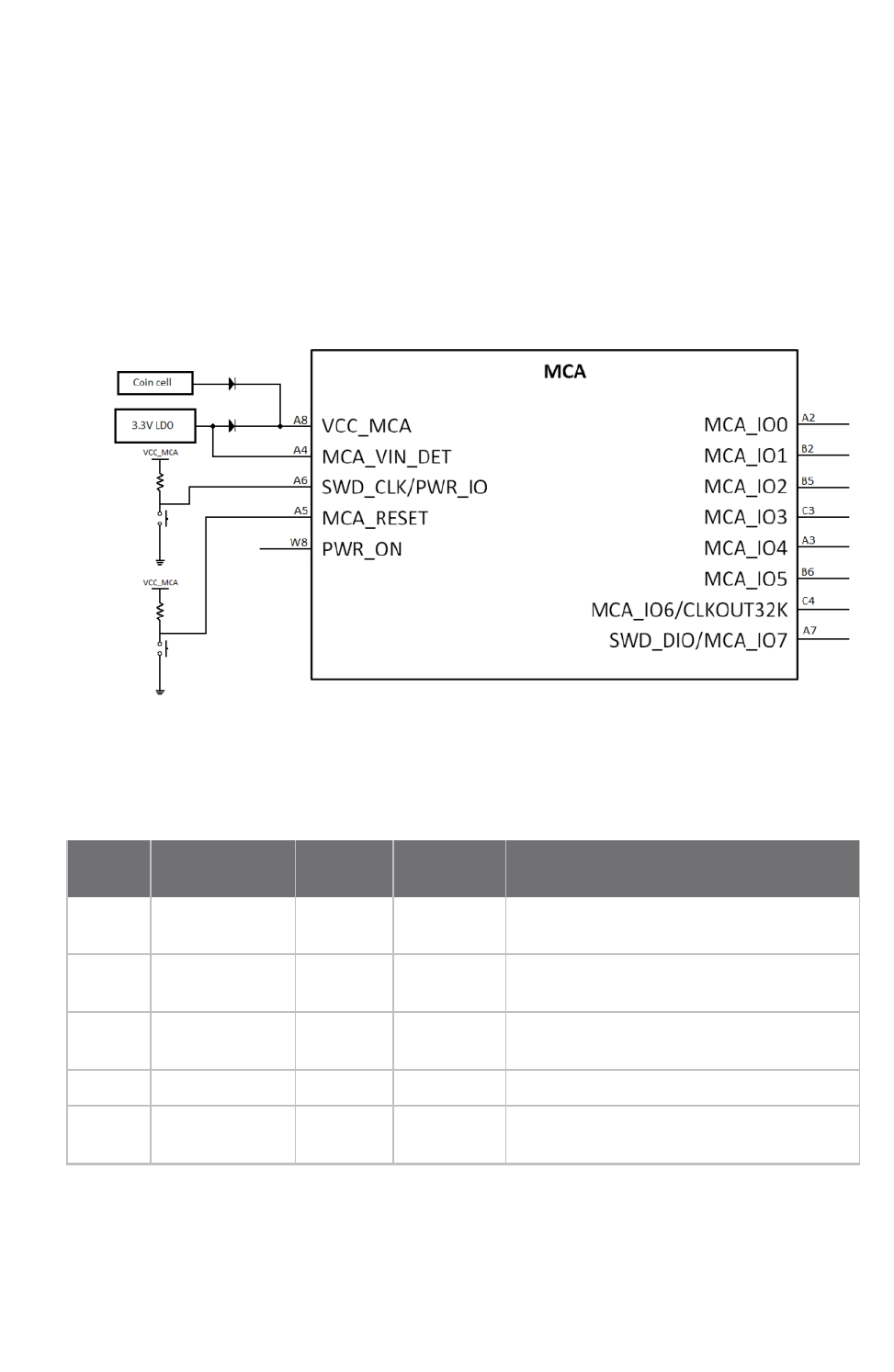
The MCA and the i.MX6UL are connected through an I2C interface and an interrupt line. The
microcontroller provides up to eight general purpose IOs that can be configured with different modes
to provide functionality such as digital input/output or ADC.
The i.MX6UL can update the MCA firmware over the I2C bus. See the MCAsoftware documentation for
additional information about this process.
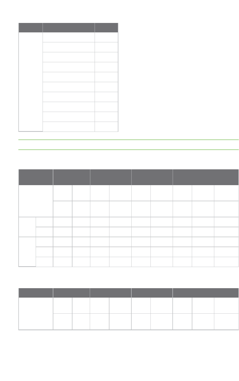
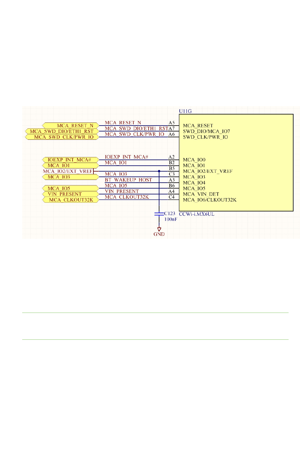
ConnectCore 6UL module lines related to the MCA
Pin
number Pin name
Pin
direction Type Definition
A2 MCA_IO0 Bi-
directional
Digital and
analog
General purpose Input/Output.
A3 MCA_IO4 Bi-
directional
Digital and
analog
General purpose Input/Output.
A4 MCA_VIN_DET Input Analog Input voltage detection line. Connect to
VCC_MCA.
A5 MCA_RESET Input Digital Reset input line, active low.
A6 SWD_CLK/PWR_
IO
Input Digital Power on/off input line, active low. SWD
interface clock line.

About the ConnectCore® 6UL Micro Controller Assist™
ConnectCore® 6UL Hardware Reference Manual 25
Pin
number Pin name
Pin
direction Type Definition
A7 SWD_DIO/MCA_
IO7
Bi-
directional
Digital General purpose Input/Ouput. SWD
interface data line.
A8 VCC_MCA Input Analog Input power supply of the MCA.
B2 MCA_IO1 Bi-
directional
Digital and
analog
General purpose Input/Output.
B5 MCA_IO2 Bi-
directional
Digital General purpose Input/Output.
B6 MCA_IO5 Bi-
directional
Digital and
analog
General purpose Input/Output.
C3 MCA_IO3 Bi-
directional
Digital and
analog
General purpose Input/Output.
C4 MCA_
IO6/CLKOUT32K
Bi-
directional
Digital General purpose Input/Output. 32KHz
clock output.
W8 PWR_ON Output Digital Output power on/off line. Set to high level*
during power off.
* low level
Reset control
Asserting and de-asserting the MCA_RESET line wakes the ConnectCore 6UL module from any power
mode (suspend/power off). Then, the microcontroller executes the programmed firmware.
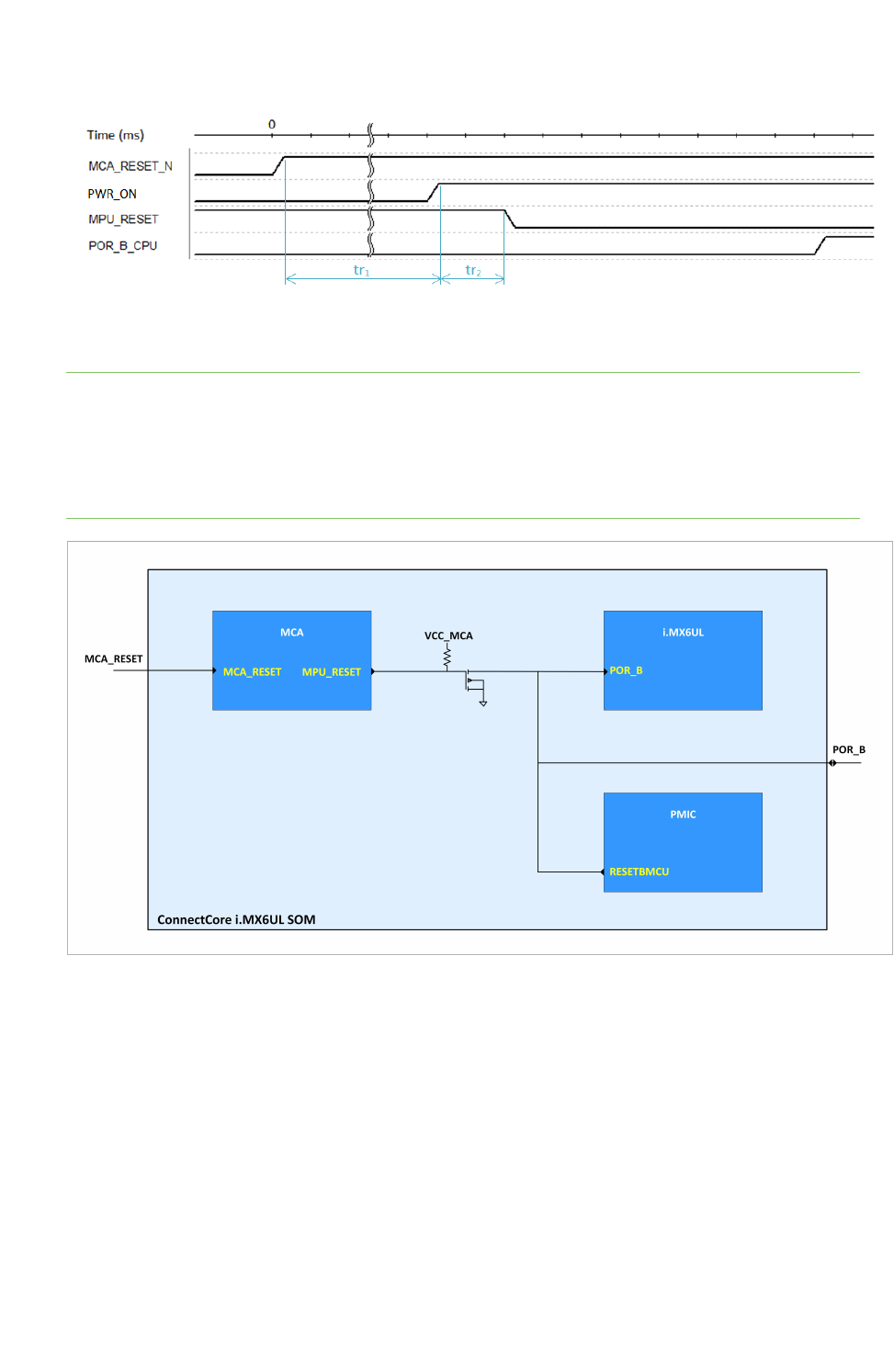
The MCA, in cooperation with the PMIC, controls the reset line of the i.MX6UL processor (POR_B). The
MCA_RESET pin is the main reset input of the ConnectCore 6UL module. This pin is a pseudo open-
drain with an internal pull up. Asserting the MCA_RESET line low sets the MCA into reset state, and it
remains in this state until the line is de-asserted.
During system initialization, the MCA performs the following actions:
nAsserts the PWR_ON line low for a configurable number of milliseconds (0-255 ms with a
default value of 50ms). This powers the PMIC off, switching off all regulated outputs of the
PMIC. You can disable this power cycle by setting the timer to 0.
nAsserts the PWR_ONline high to power the system on (assuming it was asserted low before).
nKeeps POR_B asserted low for a configurable number of miliseconds.
nAsserts the POR_B line high to start the execution of the firmware on the i.MX6UL processor.
The following time diagram represents the reset sequence. You can configure the reset timing.
Default values are as follows:
ntr1: 50 ms
ntr2: 2 ms
About the ConnectCore® 6UL Micro Controller Assist™
ConnectCore® 6UL Hardware Reference Manual 26
SeeSystem power-up sequencefor more information about the power-up sequence of
theConnectCore 6UL.
Note ThePOR_B line is also connected to the PMIC. The PMIC won't release this line until it is
switched on andthe entire starting sequence is finished (a few ms after the latest regulator is turned
on). This means that even if the MCA releases the reset line before the PMIC is ready, the CPU won't
go out of reset. This occurs on the ConnectCore 6UL module: the MCA releases the CPU reset line by
putting the MPU_RESET linehigh butthere's a delay since this GPIO goes high until the POR_B_CPU
line goes high. The delay occurs because the PMIC is still not completely initialized.
See the MCAsoftware documentation for additional information on the configuration of the MCA.
IOs
The ConnectCore 6UL MCA provides up to eight configurable IOs.
Since the general purpose IOs do not incorporate internal pull-ups or pull-downs, you may have to add
the components to the exterior of the module carrier board.
The following table lists all available MCA IOs with capabilities and module pad:

About the ConnectCore® 6UL Micro Controller Assist™
ConnectCore® 6UL Hardware Reference Manual 27
MCA IO
PAD
LGA/CS* Digital I/O IRQ capable ADC 32KHz clock 1.2 Vref
MCA_IO0 A2/76 ✔✔ ✔
MCA_IO1 B2 ✔ ✔ ✔
MCA_IO2/EXT_VREF B5 ✔ ✔ ✔
MCA_IO3 C3 ✔ ✔
MCA_IO4 A3/75 ✔ ✔
MCA_IO5 B6 ✔✔✔
MCA_IO6/CLKOUT32K C4 ✔✔
SWD_DIO/MCA_IO7 A7/71 ✔
* CS = castellated pads
Digital IOs
All MCA IOs can be configured as digital inputs/outputs, which are powered from the MCA_VCC power
rail.
The digital outputs preserve the output value set in all operating modes, except in power off and coin
cell modes where the IOs are reconfigured to high impedance state to preserve power.
Note Since the general purpose IOs do not incorporate internal pull-ups or pull-downs, you may need
to add the components to the exterior of the module carrier board.
MCA IRQs
You can configure a subset of the MCA IOs as interrupt inputs, using the MCA software to configure
the active edge of the interrupt (rising, falling, or both). When one or more MCA IRQs are activated, the
MCA interrupts the main processor through the corresponding IRQ line, signaling the active IRQs in
the IRQ status registers.The IRQ inputs can wake the system from any low power mode (suspend or
power off).
See the MCA software documentation for additional information about how to configure and access
the MCA IRQ lines.
Analog to Digital Converter
You can configure up to five MCA IOs as Analog to Digital channels in addition to the ones provided by
the i.MX6UL CPU. The index of the MCA ADC channels corresponds to the index of the MCA IO. This
means that the ADC channel 0 corresponds to the MCA_IO0, the ADC channel 1 to the MCA_IO1, and
so on.
The result of the ADC conversion for a given input voltage is inversely proportional to the reference
voltage of the ADC. For the MCA ADCs, the reference voltagecorresponds to the MCA_VCC voltage.
(Note that the i.MX6UL ADCs have a different reference voltage.) The MCA ADC provides 12-bit of
resolution with right-justified, unsigned format output. These ADCs are suitable for low-frequency
sampling(under 10 Hz). For higher frequency sampling, Digi recommends the CPU ADC channels.
See the MCAsoftware documentation for additional information about how to configure and access
the MCA ADCs.
About the ConnectCore® 6UL Micro Controller Assist™
ConnectCore® 6UL Hardware Reference Manual 28
External voltage reference
The MCA_IO2/EXT_VREF pin provides an accurate voltage reference of 1.2V that can be used to
provide a reference voltage for sensors and/or analog devices (such as comparators or DACs).
When this pin is used as external reference voltage or as the internal reference of the MCA analog-to-
digital converter,an external capacitor of 100nF must be connectedbetween the pin and ground and
as close as possible to the module pad.
The default configuration of the MCA_IO2/EXT_VREF pin is as IO. You must use software to configure
the pin for external voltage reference. See the software documentation for additional information
about how to control the function of this pin.
Note that the voltage reference continues normal operation in low power modes (suspend and power
off). Therefore, if the voltage reference is enabled during normal operation but is not required for low
power operation, Digi recommends using the software to disable it before entering low power in order
to minimize the power consumption, and re-enable it when resuming normal operation.
External 32KHz clock output
The MCA_IO6/CLKOUT32K pin is a 32.768 Hz square wave output that can be used as clock input by
peripherals requiring a low-frequency, high-accuracy clock.
Note The default configuration of theMCA_IO6/CLKOUT32K pin is as IO. You must use software to
configure the pin as 32KHz clock output. See the MCAsoftware documentation for additional
information about how to control the function of this pin.
Note that the 32KHz clock output continues normal operation in low power modes (suspend and
power off). Therefore, if the 32KHz clock output is enabled during normal operation but is not required
for low power operation, Digi recommends using the software to disable it before entering low power
in order to minimize power consumption, and re-enable it when resuming normal operation.
Watchdog
The MCA implements a watchdog timer in its firmware. The MCA watchdog resets the system, or only
the i.MX6UL CPU, if the software running on the main processor fails to execute properly and does not
reset the watchdog timer on time.

About the ConnectCore® 6UL Micro Controller Assist™
ConnectCore® 6UL Hardware Reference Manual 29
The main featuresof the MCA watchdog include:
nConfigurable timeout between 1 and 255 seconds.
nConfigurableto generate interrupt or system reset.
nConfigurable to generate full-system reset (including the MCA itself) or CPU-only reset. Full-
system reset can include a PMIC off/on, depending on the device configuration.
See the MCAsoftware documentation for additional information about how to configure and access
the watchdog timer.
Real-time clock
The MCA implements a Real-Time Clock (RTC) in its firmware. The i.MX6UL CPU internal RTCs are
disabled by default because the MCA RTC is preferred due to its superior power consumption
efficiency. To preserve the date during power-off, you must connect a coin cell battery following the
design notes provided in the Power Supply Architecture section. You must also connect the MCA line
VIN_PRESENT following the design guidelines inPower supply architecture in order to detect power
loss and automatically switch to RTC mode.
The main features of the MCA RTC include:
nDate/time registers to keep the system time (backed up by the coin cell battery).
nProgrammable alarm to generate and interrupt. This alarm can be used to wake the system
from low power modes (suspend and power off).
See the MCAsoftware documentation for additional information about how to configure and access
the watchdog timer.
Tamper support
The tamper interface provides a mechanism to detect any unauthorized attempt to access the
system, such as the opening of the enclosure. The tamper support included in the ConnectCore 6UL is
implemented in the MCA with the following capabilities:
nConfigure up to two tamper interfaces, each with an optional digital output.
nRely on tamper detection event in power-off and coin cell (battery backup) modes.
nRegister tamper event(s) in the non-volatile memory of the MCA.
nAlert the host CPU when a tamper event occurs.
nRespond to a tamper attack with actions such as erasing a critical data partition of the flash.
Tamper pins
The ConnectCore 6UL module supports up to two tamper interfaces (tamper0 and tamper1). Each
interface has an associated IO (tamper pin) used to detect the tamper event (through a voltage
transition on the IO) and, optionally, an output IO (tamper output) that can be used to enable or
disable peripherals, for instance to cut the power of a peripheral. The IOs of each tamper interface
can be configured independently and have the following configuration options:
nThe MCA IO used for tamper detection, from the available MCA IOs that are IRQ-capable.
nThe active level (tampering) of the tamper input.
nThe MCA IO used as tamper output, when enabled, that is activated when a tamper condition
has not been acknowledged.
nThe logic level that is set in the tamper output when a tamper event occurs.

About the ConnectCore® 6UL Micro Controller Assist™
ConnectCore® 6UL Hardware Reference Manual 30
The MCA IO table provides information about the capabilities of the MCA IO pins so you can easily
identify suitable IOs to be used as tamper inputs. Any MCA IO pin can be configured as tamper output.
Tamper pin configuration
To learn ore about tamper pin configuration, see Tamper detection interface in the software
documentation.
Power management
The MCA plays a key role in the power management activities of the ConnectCore 6UL module. In
cooperation with the i.MX6UL processor, the MCA controls the power states of the PMIC, provides
multiple wake up sources to transition between power modes. It also allocates dedicated signals to
capture power events and indicate the system power state, allowing you to control external power
sources and indicators.
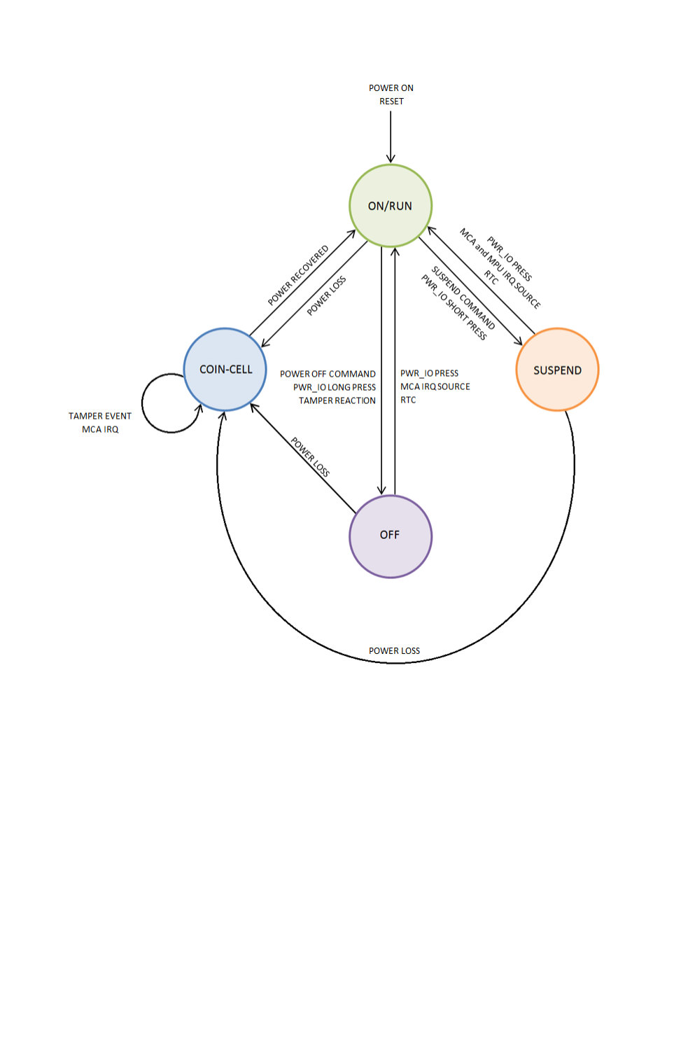
Power modes
The module provides four different power operating modes: ON/RUN, OFF, SUSPEND, and COIN-CELL.
The following figure shows the state diagram and the events to switch between states.
About the ConnectCore® 6UL Micro Controller Assist™
ConnectCore® 6UL Hardware Reference Manual 31
ON/RUN mode
The module enters the ON state after a power-on or system-reset event. In this mode, the PMIC is
running at full power so all voltage regulators are generating the nominal voltage for this mode. The
cpu reset line is de-asserted and the processor is running at normal speed, performing DVFS if the
system was configured to do so. In this state, the PWR_ON line is asserted low, indicating that the
module is ON.
Note that the specific state of the regulators (on/off) and the voltage in this mode are controlled by
the firmware running on the i.MX6UL processor. The PMIC starts with the default settings configured
on the OTP area, but once the software takes control it applies the specific configuration
implemented in the firmware.
SUSPEND mode
The suspend mode (also known as suspend-to-ram mode) is the low-power mode that allows the
module to preserve ram content. When the module enters SUSPEND, the following actions take place:

About the ConnectCore® 6UL Micro Controller Assist™
ConnectCore® 6UL Hardware Reference Manual 32
nThe processor goes into low power, disabling as much functionality as possible and keeping
active only the peripherals configured to wake the system from SUSPEND.
nThe DDR memory is set to self-refresh mode to preserve its contents while reducing power
consumption.
nThe PMIC goes into standby mode, configuring the regulators in the configured mode (on, off,
with a different voltage compared to ON state).
nThe MCA goes into sleep mode, keeping active the peripherals that always run in low power
modes (like the RTC) and those configured to wake up the system (such as IRQs and power IO).
OFF mode
The module enters OFF mode after a power-off event. In this mode:
nThe PMIC is set to the OFF state and all the voltage regulators, except VSNVS, are switched off.
nThe PWR_ON line is asserted low, indicating that the module is in OFF state.
nThe MCA goes into sleep mode, keeping active the peripherals that always run in low-power
modes (like the RTC) and those configured to wake up the system (such as IRQs and power IO).
COIN-CELL mode
In COIN-CELL mode, the module only powers the MCA from the coin-cell battery, leaving the rest of
the module power inputs switched off. In this mode, the MCA remains in sleep mode, updating the RTC
and monitoring the following events:
nTamper events that would be registered in the NVRAM memory of the MCA and would assert
the Tamper output if enabled.
nPower in MCA_VIN_DET, which indicates that there is sufficient voltage to generate a power-
on event.
Power IO signal/Power button
The MCA provides a signal (PWR_IO) to detect external events that trigger a transition between the
different power modes described in Power modes. The pin has wake-up interrupt/event capabilities, it
is active low, and it does not provide an internal pull-up. (The pull-up resistor must be added externally
if required.) This signal is ideal for connecting a power button or the output of a peripheral that
controls the power state of the module and its transitions. The firmware provides a configurable
debounce filter to improve noise immunity and filter rebounds on push buttons. When the PWR_IO
signal is asserted low, one of the following events occurs:
nIf the duration of the assertion is short (time configurable by the user) the system will trigger
an interrupt that, commonly, indicates the host processor that the system should enter
suspend state.
nIf the low-pulse duration is long enough (again, time configurable by the user) the system will
trigger the power off interrupt, to indicate the host processor to start a transition to OFF
state.
nIf the system does not enter OFF state before a configurable guard timer expires, the MCA will
automatically set the OFF state.
Digi recommends you use an external pull-up resistor of 100K to VCC_MCA in this SWD_CLK/PWR_IO
line.

About the ConnectCore® 6UL CryptoAuthentication device
ConnectCore® 6UL Hardware Reference Manual 33
MCA_VIN_DET signal
The on-module MCA is powered from a dedicated external power rail, VCC_MCA. As recommended in
the reference designs (see Power supply architecture), this power supply is provided by an external
3.3V regulator. If the system requires system time to be kept when there is no power, you must use a
coin-cell battery to power the MCA while it keeps the RTC up to date in low-power mode. The MCA
uses the MCA_VIN_DET input to monitor the input voltage and automatically switch to RTC mode to
keep the system time and save power. Follow the design guidelines provided inPower supply
architectureto apply the proper voltage to MCA_VIN_DET when there is a coin-cell battery in the
system and when there is not.
MCA firmware update
The i.MX6UL processor can update the firmware of the MCA. See the MCAsoftware documentation for
additional information about the MCA firmware update process.
CryptoAuthentication device
The ConnectCore 6UL module includes an Atmel CryptoAuthentication Device. This is a highly secure
cryptographic co-processor with secure hardware-based key storage. It includes the following
features:
nPerforms high-speed public key (PKI) algorithms (ECDSA and ECDH).
nNIST standard P256 elliptic curve support.
nSHA-256 hash algorithm with HMAC option.
n256-bit key length.
nStorage for up to 16 keys.
nTwo high-endurance monotonic counters.
nGuaranteed unique 72-bit serial number.
nInternal High-quality FIPS Random Number Generator (RNG).
n10 Kb EEPROM memory.
See the software documentation for information about supported cryptoauthentication features.
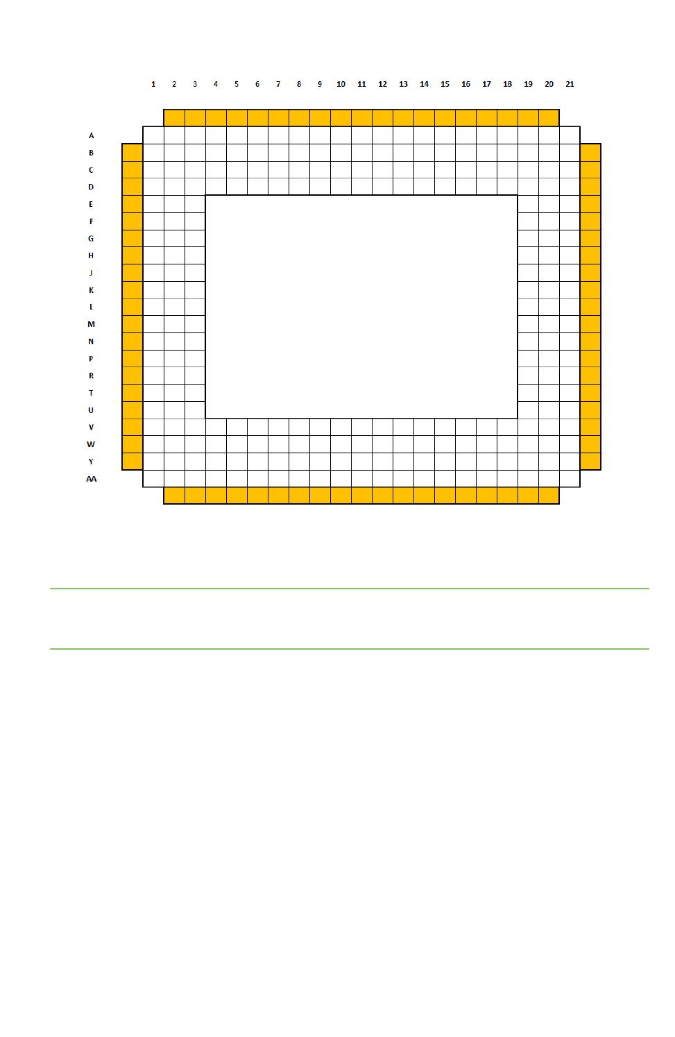
Module pinout - general layout
The ConnectCore 6UL module has a mixed pad structure. The module provides 245 LGA pins, 76 of
them connected to the peripheral castellated pads. The general layout can be found on the following
diagram:
About the ConnectCore® 6UL Module pinout - general layout
ConnectCore® 6UL Hardware Reference Manual 34
lWhite cells: LGA pads
lOrange cells: castellated pads
Note Pad A1 is unconnected. This pad is meant for module-orientation purposes; its shape is square,
whereas all other pads are circular. Pad A1 should not be soldered down to a corresponding pad on
the carrier board.

ConnectCore® 6UL Hardware Reference Manual 35
External signals and pin multiplexing
The following tables provide the pinout information of the ConnectCore 6UL module. For additional information related to the signals listed
in the table, refer to the NXP i.MX6UL technical documentation.
Castellated pad signals and multiplexing
Castellated
pad
ConnectCore
6UL pad
ConnectCore 6UL
signal name
i.MX6UL
pad name Multiplexing
Power
group Comments
1 / B1 CPAD1 VCC_LICELL -VCC_
LICELL
Coin cell supply
2 / C1 CPAD2 VSYS -VSYS Power line
3 / D1 CPAD3 VPWR -VPWR Power line
4 / E1 CPAD4 LDOG -LDOG PMIC output (Front-end LDO)
5 / F1 CPAD5 GND --
6 / G1 CPAD6 VSYS -VSYS Power line
7 / H1 CPAD7 VSYS2 -VSYS2 Power line
8 / J1 CPAD8 GND --
9 / K1 CPAD9 3V3_EXT -3V3_EXT Power line (PMIC SW2 output)

ConnectCore® 6UL Hardware Reference Manual 36
Castellated
pad
ConnectCore
6UL pad
ConnectCore 6UL
signal name
i.MX6UL
pad name Multiplexing
Power
group Comments
10 / L1 CPAD10 LCD_DATA8 LCD_DATA08 ALT0: LCDIF_DATA08
ALT1: SPDIF_IN
ALT2:
ALT3: CSI_DATA16
ALT4: EIM_DATA0
ALT5: GPIO3_IO13
ALT6: SRC_BT_CFG08
ALT7:
ALT8: FLEXCAN1_TX
VCC_
LCD
11 / M1 CPAD11 LCD_DATA9 LCD_DATA09 ALT0: LCDIF_DATA09
ALT1: SAI3_MCLK
ALT2:
ALT3: CSI_DATA17
ALT4: EIM_DATA1
ALT5: GPIO3_IO14
ALT6: SRC_BT_CFG09
ALT7:
ALT8: FLEXCAN1_RX
VCC_
LCD
12 / N1 CPAD12 VCC_ENET VCC_
ENET
Power line (expected 3.3 V)
13 / P1 CPAD13 POR_B VDDIO Input reset line of the module
(active low)

ConnectCore® 6UL Hardware Reference Manual 37
Castellated
pad
ConnectCore
6UL pad
ConnectCore 6UL
signal name
i.MX6UL
pad name Multiplexing
Power
group Comments
14 / R1 CPAD14 CSI_MCLK CSI_MCLK ALT0: CSI_MCLK
ALT1: USDHC2_CD_B
ALT2: NAND_CE2_B
ALT3: I2C1_SDA
ALT4: EIM_CS0_B
ALT5: GPIO4_IO17
ALT6: SNVS_VIO_5_
CTL
ALT7:
ALT8: UART6_TX
NVCC_
CSI
15 / T1 CPAD15 CSI_PIXCLK CSI_PIXCLK ALT0: CSI_PIXCLK
ALT1: USDHC2_WP
ALT2: NAND_CE3_B
ALT3: I2C1_SCL
ALT4: EIM_OE
ALT5: GPIO4_IO18
ALT6: SNVS_HP_VIO_5
ALT7:
ALT8: UART6_RX
NVCC_
CSI
16 / U1 CPAD16 CSI_DATA1 CSI_DATA01 ALT0: CSI_DATA03
ALT1: USDHC2_DATA1
ALT2: SIM1_PORT1_
SVEN
ALT3: ECSPI2_SS0
ALT4: EIM_AD01
ALT5: GPIO4_IO22
ALT6: SAI1_MCLK
ALT7:
ALT8: UART5_RX
NVCC_
CSI

ConnectCore® 6UL Hardware Reference Manual 38
Castellated
pad
ConnectCore
6UL pad
ConnectCore 6UL
signal name
i.MX6UL
pad name Multiplexing
Power
group Comments
17 / V1 CPAD17 CSI_HSYNC CSI_HSYNC ALT0: CSI_HSYNC
ALT1: USDHC2_CMD
ALT2: SIM1_PORT1_
PD
ALT3: I2C2_SCL
ALT4: EIM_LBA_B
ALT5: GPIO4_IO20
ALT6: PWM8_OUT
ALT7:
ALT8: UART6_CTS_B
NVCC_
CSI
18 / W1 CPAD18 GPIO1_5 GPIO1_IO05 ALT0: ENET2_REF_
CLK2
ALT1: PWM4_OUT
ALT2: USB_OTG2_ID
ALT3: CSI_FIELD
ALT4: USDHC1_
VSELECT
ALT5: GPIO1_IO05
ALT6: ENET2_1588_
EVENT0_OUT
ALT7:
ALT8: UART5_RX
NVCC_
GPIO
19 / Y1 CPAD19 BOOT_MODE1 VDD_
SNVS_IN

ConnectCore® 6UL Hardware Reference Manual 39
Castellated
pad
ConnectCore
6UL pad
ConnectCore 6UL
signal name
i.MX6UL
pad name Multiplexing
Power
group Comments
20 / AA2 CPAD20 CSI_DATA0 CSI_DATA00 ALT0: CSI_DATA02
ALT1: USDHC2_DATA0
ALT2: SIM1_PORT1_
RST_B
ALT3: ECSPI2_SCLK
ALT4: EIM_AD00
ALT5: GPIO4_IO21
ALT6: SRC_INT_BOOT
ALT7:
ALT8: UART5_TX
NVCC_
CSI
21 / AA3 CPAD21 CSI_VSYNC CSI_VSYNC ALT0: CSI_VSYNC
ALT1: USDHC2_CLK
ALT2: SIM1_PORT1_
CLK
ALT3: I2C2_SDA
ALT4: EIM_RW
ALT5: GPIO4_IO19
ALT6: PWM7_OUT
ALT7:
ALT8: UART6_RTS_B
NVCC_
CSI
22 / AA4 CPAD22 CSI_DATA2 CSI_DATA02 ALT0: CSI_DATA04
ALT1: USDHC2_DATA2
ALT2: SIM1_PORT1_
TRXD
ALT3: ECSPI2_MOSI
ALT4: EIM_AD02
ALT5: GPIO4_IO23
ALT6: SAI1_RX_SYNC
ALT7:
ALT8: UART5_RTS_B
NVCC_
CSI

ConnectCore® 6UL Hardware Reference Manual 40
Castellated
pad
ConnectCore
6UL pad
ConnectCore 6UL
signal name
i.MX6UL
pad name Multiplexing
Power
group Comments
23 / AA5 CPAD23 CSI_DATA3 CSI_DATA03 ALT0: CSI_DATA05
ALT1: USDHC2_DATA3
ALT2: SIM2_PORT1_
PD
ALT3: ECSPI2_MISO
ALT4: EIM_AD03
ALT5: GPIO4_IO24
ALT6: SAI1_RX_BCLK
ALT7:
ALT8: UART5_CTS_B
NVCC_
CSI
24 / AA6 CPAD24 UART5_TX UART5_TX_
DATA
ALT0: UART5_TX
ALT1: ENET2_CRS
ALT2: I2C2_SCL
ALT3: CSI_DATA14
ALT4: CSU_CSU_
ALARM_AUT00
ALT5: GPIO1_IO30
ALT6:
ALT7:
ALT8: ECSPI2_MOSI
NVCC_
UART
25 / AA7 CPAD25 UART5_RX UART5_RX_
DATA
ALT0: UART5_RX
ALT1: ENET2_COL
ALT2: I2C2_SDA
ALT3: CSI_DATA15
ALT4: CSU_CSU_INT_
DEB
ALT5: GPIO1_IO31
ALT6:
ALT7:
ALT8: ECSPI2_MISO
NVCC_
UART

ConnectCore® 6UL Hardware Reference Manual 41
Castellated
pad
ConnectCore
6UL pad
ConnectCore 6UL
signal name
i.MX6UL
pad name Multiplexing
Power
group Comments
26 / AA8 CPAD26 USB_OTG1_P USB_OTG1_
DP
USB differential data line
27 / AA9 CPAD27 USB_OTG1_N USB_OTG1_
DN
USB differential data line
28 / AA10 CPAD28 GND --
29 / AA11 CPAD29 USB_OTG1_VBUS USB_OTG1_
VBUS
USB_
VBUS
Power line
30 / AA12 CPAD30 GPIO1_4 GPIO1_IO04 ALT0: ENET1_REF_
CLK1
ALT1: PWM3_OUT
ALT2: USB_OTG1_PWR
ALT3: ANATOP_24M_
OUT
ALT4: USDHC1_
RESET_B
ALT5: GPIO1_IO04
ALT6: ENET2_1588_
EVENT0_IN
ALT7:
ALT8: UART5_TX
NVCC_
GPIO

ConnectCore® 6UL Hardware Reference Manual 42
Castellated
pad
ConnectCore
6UL pad
ConnectCore 6UL
signal name
i.MX6UL
pad name Multiplexing
Power
group Comments
31 / AA13 CPAD31 GPIO1_0 GPIO1_IO00 ALT0: I2C2_SCL
ALT1: GPT1_
CAPTURE1
ALT2: USB_OTG1_ID
ALT3: ENET1_REF_
CLK1
ALT4: MQS_RIGHT
ALT5: GPIO1_IO00
ALT6: ENET1_1588_
EVENT0_IN
ALT7: SRC_SYSTEM_
RESET
ALT8: WDOG3_WDOG_
B
NVCC_
GPIO
32 / AA14 CPAD32 GPIO1_1 GPIO1_IO01 ALT0: I2C2_SDA
ALT1: GPT1_
COMPARE1
ALT2: USB_OTG1_OC
ALT3: ENET2_REF_
CLK2
ALT4: MQS_LEFT
ALT5: GPIO1_IO01
ALT6: ENET1_1588_
EVENT0_OUT
ALT7: SRC_EARLY_
RESET
ALT8: WDOG1_WDOG_
B
NVCC_
GPIO

ConnectCore® 6UL Hardware Reference Manual 43
Castellated
pad
ConnectCore
6UL pad
ConnectCore 6UL
signal name
i.MX6UL
pad name Multiplexing
Power
group Comments
33 / AA15 CPAD33 JTAG_MOD JTAG_MOD ALT0: SJC_MOD
ALT1: GPT2_CLK
ALT2: SPDIF_OUT
ALT3: XTALOSC_REF_
CLK_25M
ALT4: CCM_PMIC_
READY
ALT5: GPIO1_IO10
ALT6: SDMA_EXT_
EVENT00
ALT7:
ALT8:
NVCC_
GPIO
34 / AA16 CPAD34 JTAG_TMS JTAG_TMS ALT0: SJC_TMS
ALT1: GPT2_
CAPTURE1
ALT2: SAI2_MCLK
ALT3: CCM_CLKO1
ALT4: CCM_WAIT
ALT5: GPIO1_IO11
ALT6: SDMA_EXT_
EVENT01
ALT7:
ALT8: EPIT1_OUT
NVCC_
GPIO
35 / AA17 CPAD35 USB_OTG2_P USB_OTG2_
DP
USB differential data line
36 / AA18 CPAD36 USB_OTG2_N USB_OTG2_
DN
USB differential data line

ConnectCore® 6UL Hardware Reference Manual 44
Castellated
pad
ConnectCore
6UL pad
ConnectCore 6UL
signal name
i.MX6UL
pad name Multiplexing
Power
group Comments
37 / AA19 CPAD37 GPIO1_7 GPIO1_IO07 ALT0: ENET1_MDC
ALT1: ENET2_MDC
ALT2: USB_OTG_
HOST_MODE
ALT3: CSI_PIXCLK
ALT4: USDHC2_CD_B
ALT5: GPIO1_IO07
ALT6: CCM_STOP
ALT7:
ALT8: UART1_RTS_B
NVCC_
GPIO
38 / AA20 CPAD38 GPIO1_6 GPIO1_IO06 ALT0: ENET1_MDIO
ALT1: ENET2_MDIO
ALT2: USB_OTG_PWR_
WAKE
ALT3: CSI_MCLK
ALT4: USDHC2_WP
ALT5: GPIO1_IO06
ALT6: CCM_WAIT
ALT7: CCM_REF_EN_B
ALT8: UART1_CTS_B
NVCC_
GPIO
39 / Y21 CPAD39 JTAG_TDO JTAG_TDO ALT0: SJC_TDO
ALT1: GPT2_
CAPTURE2
ALT2: SAI2_TX_SYNC
ALT3: CCM_CLKO2
ALT4: CCM_STOP
ALT5: GPIO1_IO12
ALT6: MQS_RIGHT
ALT7:
ALT8: EPIT2_OUT
NVCC_
GPIO

ConnectCore® 6UL Hardware Reference Manual 45
Castellated
pad
ConnectCore
6UL pad
ConnectCore 6UL
signal name
i.MX6UL
pad name Multiplexing
Power
group Comments
40 / W21 CPAD40 JTAG_TCK JTAG_TCK ALT0: SJC_TCK
ALT1: GPT2_
COMPARE2
ALT2: SAI2_RX_DATA
ALT3:
ALT4: PWM7_OUT
ALT5: GPIO1_IO14
ALT6: OSC32K_32K_
OUT
ALT7:
ALT8: SIM2_POWER_
FAIL
NVCC_
GPIO
41 / V21 CPAD41 JTAG_TDI JTAG_TDI ALT0: SJC_TDI
ALT1: GPT2_
COMPARE1
ALT2: SAI2_TX_BCLK
ALT3:
ALT4: PWM6_OUT
ALT5: GPIO1_IO13
ALT6: MQS_LEFT
ALT7:
ALT8: SIM1_POWER_
FAIL
NVCC_
GPIO

ConnectCore® 6UL Hardware Reference Manual 46
Castellated
pad
ConnectCore
6UL pad
ConnectCore 6UL
signal name
i.MX6UL
pad name Multiplexing
Power
group Comments
42 / U21 CPAD42 JTAG_nTRST JTAG_TRST_
B
ALT0: SJC_TRSTB
ALT1: GPT2_
COMPARE3
ALT2: SAI2_TX_DATA
ALT3:
ALT4: PWM8_OUT
ALT5: GPIO1_IO15
ALT6: ANATOP_24M_
OUT
ALT7:
ALT8:CAAM_RNG_
OSC_OBS
NVCC_
GPIO
43 / T21 CPAD43 UART2_TX UART2_TX_
DATA
ALT0: UART2_TX
ALT1: ENET1_TDATA02
ALT2: I2C4_SCL
ALT3: CSI_DATA06
ALT4: GPT1_
CAPTURE1
ALT5: GPIO1_IO20
ALT6:
ALT7:
ALT8: ECSPI3_SS0
NVCC_
UART

ConnectCore® 6UL Hardware Reference Manual 47
Castellated
pad
ConnectCore
6UL pad
ConnectCore 6UL
signal name
i.MX6UL
pad name Multiplexing
Power
group Comments
44 / R21 CPAD44 UART2_RX UART2_RX_
DATA
ALT0: UART2_RX
ALT1: ENET1_TDATA03
ALT2: I2C4_SDA
ALT3: CSI_DATA07
ALT4: GPT1_
CAPTURE2
ALT5: GPIO1_IO21
ALT6:
ALT7: SJC_DONE
ALT8: ECSPI3_SCLK
NVCC_
UART
45 / P21 CPAD45 GND --
46 / N21 CPAD46 UART2_CTS# UART2_CTS_
B
ALT0: UART2_CTS_B
ALT1: ENET1_CRS
ALT2: FLEXCAN2_TX
ALT3: CSI_DATA08
ALT4: GPT1_
COMPARE2
ALT5: GPIO1_IO22
ALT6:
ALT7: SJC_DE_B
ALT8: ECSPI3_MOSI
NVCC_
UART

ConnectCore® 6UL Hardware Reference Manual 48
Castellated
pad
ConnectCore
6UL pad
ConnectCore 6UL
signal name
i.MX6UL
pad name Multiplexing
Power
group Comments
47 / M21 CPAD47 UART2_RTS# UART2_RTS_
B
ALT0: UART2_RTS_B
ALT1: ENET1_COL
ALT2: FLEXCAN2_RX
ALT3: CSI_DATA09
ALT4: GPT1_
COMPARE3
ALT5: GPIO1_IO23
ALT6:
ALT7: SJC_FAIL
ALT8: ECSPI3_MISO
NVCC_
UART
48 / L21 CPAD48 ENET1_RX_DATA0 ENET1_RX_
DATA0
ALT0: ENET1_RDATA00
ALT1: UART4_RTS_B
ALT2: PWM1_OUT
ALT3: CSI_DATA16
ALT4: FLEXCAN1_TX
ALT5: GPIO2_IO00
ALT6: KPP_ROW00
ALT7:
ALT8: USDHC1_LCTL
NVCC_
ENET
49 / K21 CPAD49 ENET1_RX_EN ENET1_RX_
EN
ALT0: ENET1_RX_EN
ALT1: UART5_RTS_B
ALT2: OSC32K_32K_
OUT
ALT3: CSI_DATA18
ALT4: FLEXCAN2_TX
ALT5: GPIO2_IO02
ALT6: KPP_ROW01
ALT7:
ALT8: USDHC1_
VSELECT
NVCC_
ENET

ConnectCore® 6UL Hardware Reference Manual 49
Castellated
pad
ConnectCore
6UL pad
ConnectCore 6UL
signal name
i.MX6UL
pad name Multiplexing
Power
group Comments
50 / J21 CPAD50 ENET1_RX_ER ENET1_RX_
ER
ALT0: ENET1_RX_ER
ALT1: UART7_RTS_B
ALT2: PWM8_OUT
ALT3: CSI_DATA23
ALT4: EIM_CRE
ALT5: GPIO2_IO07
ALT6: KPP_COL03
ALT7:
ALT8: GPT1_
CAPTURE2
NVCC_
ENET
51 / H21 CPAD51 ENET1_TX_DATA1 ENET1_TX_
DATA1
ALT0: ENET1_TDATA01
ALT1: UART6_CTS_B
ALT2: PWM5_OUT
ALT3: CSI_DATA20
ALT4: ENET2_MDIO
ALT5: GPIO2_IO04
ALT6: KPP_ROW02
ALT7:
ALT8: WDOG1_WDOG_
RST_B_DEB
NVCC_
ENET
52 / G21 CPAD52 ENET1_TX_EN ENET1_TX_
EN
ALT0: ENET1_TX_EN
ALT1: UART6_RTS_B
ALT2: PWM6_OUT
ALT3: CSI_DATA21
ALT4: ENET2_MDC
ALT5: GPIO2_IO05
ALT6: KPP_COL02
ALT7:
ALT8: WDOG2_WDOG_
RST_B_DEB
NVCC_
ENET

ConnectCore® 6UL Hardware Reference Manual 50
Castellated
pad
ConnectCore
6UL pad
ConnectCore 6UL
signal name
i.MX6UL
pad name Multiplexing
Power
group Comments
53 / F21 CPAD53 ENET1_TX_CLK ENET1_TX_
CLK
ALT0: ENET1_TX_CLK
ALT1: UART7_CTS_B
ALT2: PWM7_OUT
ALT3: CSI_DATA22
ALT4: ENET1_REF_
CLK1
ALT5: GPIO2_IO06
ALT6: KPP_ROW03
ALT7:
ALT8: GPT1_CLK
NVCC_
ENET
54 / E21 CPAD54 ENET1_RX_DATA1 ENET1_RX_
DATA1
ALT0: ENET1_RDATA01
ALT1: UART4_CTS_B
ALT2: PWM2_OUT
ALT3: CSI_DATA17
ALT4: FLEXCAN1_RX
ALT5: GPIO2_IO01
ALT6: KPP_COL00
ALT7:
ALT8: USDHC2_LCTL
NVCC_
ENET
55 / D21 CPAD55 ENET1_TX_DATA0 ENET1_TX_
DATA0
ALT0: ENET1_TDATA00
ALT1: UART5_CTS_B
ALT2: ANATOP_24M_
OUT
ALT3: CSI_DATA19
ALT4: FLEXCAN2_RX
ALT5: GPIO2_IO03
ALT6: KPP_COL01
ALT7:
ALT8: USDHC2_
VSELECT
NVCC_
ENET

ConnectCore® 6UL Hardware Reference Manual 51
Castellated
pad
ConnectCore
6UL pad
ConnectCore 6UL
signal name
i.MX6UL
pad name Multiplexing
Power
group Comments
56 / C21 CPAD56 LCD_CLK LCD_CLK ALT0: LCDIF_CLK
ALT1: LCDIF_WR_RWN
ALT2: UART4_TX
ALT3: SAI3_MCLK
ALT4: EIM_CS2_B
ALT5: GPIO3_IO00
ALT6:
ALT7:
ALT8: WDOG1_WDOG_
RST_B_DEB
NVCC_
LCD
57 / B21 CPAD57 LCD_HSYNC LCD_HSYNC ALT0: LCDIF_HSYNC
ALT1: LCDIF_RS
ALT2: UART4_CTS_B
ALT3: SAI3_TX_BCLK
ALT4: WDOG3_WDOG_
RST_B_DEB
ALT5: GPIO3_IO02
ALT6:
ALT7:
ALT8: ECSPI2_SS1
NVCC_
LCD
58 / A20 CPAD58 LCD_DATA4 LCD_DATA04 ALT0: LCDIF_DATA04
ALT1: UART8_CTS_B
ALT2:
ALT3: ENET2_1588_
EVENT2_IN
ALT4: SPDIF_SR_CLK
ALT5: GPIO3_IO09
ALT6: SRC_BT_CFG04
ALT7:
ALT8: SAI1_TX_DATA
NVCC_
LCD

ConnectCore® 6UL Hardware Reference Manual 52
Castellated
pad
ConnectCore
6UL pad
ConnectCore 6UL
signal name
i.MX6UL
pad name Multiplexing
Power
group Comments
59 / A19 CPAD59 LCD_RESET LCD_RESET ALT0: LCDIF_RESET
ALT1: LCDIF_CS
ALT2: CA7_MX6UL_
EVENTI
ALT3: SAI3_TX_DATA
ALT4: WDOG1_WDOG_
ANY
ALT5: GPIO3_IO04
ALT6:
ALT7:
ALT8: ECSPI2_SS3
NVCC_
LCD
60 / A18 CPAD60 LCD_DATA0 LCD_DATA00 ALT0: LCDIF_DATA00
ALT1: PWM1_OUT
ALT2:
ALT3: ENET1_1588_
EVENT2_IN
ALT4: I2C3_SDA
ALT5: GPIO3_IO05
ALT6: SRC_BT_CFG00
ALT7:
ALT8: SAI1_MCLK
NVCC_
LCD

ConnectCore® 6UL Hardware Reference Manual 53
Castellated
pad
ConnectCore
6UL pad
ConnectCore 6UL
signal name
i.MX6UL
pad name Multiplexing
Power
group Comments
61 / A17 CPAD61 LCD_DATA3 LCD_DATA03 ALT0: LCDIF_DATA03
ALT1: PWM4_OUT
ALT2:
ALT3: ENET1_1588_
EVENT3_OUT
ALT4: I2C4_SCL
ALT5: GPIO3_IO08
ALT6: SRC_BT_CFG03
ALT7:
ALT8: SAI1_RX_DATA
NVCC_
LCD
62 / A16 CPAD62 LCD_DATA6 LCD_DATA06 ALT0: LCDIF_DATA06
ALT1: UART7_CTS_B
ALT2:
ALT3: ENET2_1588_
EVENT3_IN
ALT4: SPDIF_LOCK
ALT5: GPIO3_IO11
ALT6: SRC_BT_CFG06
ALT7:
ALT8: ECSPI1_SS2
NVCC_
LCD
63 / A15 CPAD63 LCD_DATA7 LCD_DATA07 ALT0: LCDIF_DATA07
ALT1: UART7_RTS_B
ALT2:
ALT3: ENET2_1588_
EVENT3_OUT
ALT4: SPDIF_EXT_CLK
ALT5: GPIO3_IO12
ALT6: SRC_BT_CFG07
ALT7:
ALT8: ECSPI1_SS3
NVCC_
LCD

ConnectCore® 6UL Hardware Reference Manual 54
Castellated
pad
ConnectCore
6UL pad
ConnectCore 6UL
signal name
i.MX6UL
pad name Multiplexing
Power
group Comments
64 / A14 CPAD64 LCD_DATA5 LCD_DATA05 ALT0: LCDIF_DATA05
ALT1: UART8_RTS_B
ALT2:
ALT3: ENET2_1588_
EVENT2_OUT
ALT4: SPDIF_OUT
ALT5: GPIO3_IO10
ALT6: SRC_BT_CFG05
ALT7:
ALT8: ECSPI1_SS1
NVCC_
LCD
65 / A13 CPAD65 GND --
66 / A12 CPAD66 LCD_DATA2 LCD_DATA02 ALT0: LCDIF_DATA02
ALT1: PWM3_OUT
ALT2:
ALT3: ENET1_1588_
EVENT3_IN
ALT4: I2C4_SDA
ALT5: GPIO3_IO07
ALT6: SRC_BT_CFG02
ALT7:
ALT8: SAI1_TX_BCLK
NVCC_
LCD

ConnectCore® 6UL Hardware Reference Manual 55
Castellated
pad
ConnectCore
6UL pad
ConnectCore 6UL
signal name
i.MX6UL
pad name Multiplexing
Power
group Comments
67 / A11 CPAD67 LCD_VSYNC LCD_VSYNC ALT0: LCDIF_VSYNC
ALT1: LCDIF_BUSY
ALT2: UART4_RTS_B
ALT3: SAI3_RX_DATA
ALT4: WDOG2_WDOG_
B
ALT5: GPIO3_IO03
ALT6:
ALT7:
ALT8: ECSPI2_SS2
NVCC_
LCD
68 / A10 CPAD68 LCD_DATA1 LCD_DATA01 ALT0: LCDIF_DATA01
ALT1: PWM2_OUT
ALT2:
ALT3: ENET1_1588_
EVENT2_OUT
ALT4: I2C3_SCL
ALT5: GPIO3_IO06
ALT6: SRC_BT_CFG01
ALT7:
ALT8: SAI1_TX_SYNC
NVCC_
LCD
69 / A9 CPAD69 LCD_ENABLE LCD_ENABLE ALT0: LCDIF_ENABLE
ALT1: LCDIF_RD_E
ALT2: UART4_RX
ALT3: SAI3_TX_SYNC
ALT4: EIM_CS3_B
ALT5: GPIO3_IO01
ALT6:
ALT7:
ALT8: ECSPI2_RDY
NVCC_
LCD

ConnectCore® 6UL Hardware Reference Manual 56
Castellated
pad
ConnectCore
6UL pad
ConnectCore 6UL
signal name
i.MX6UL
pad name Multiplexing
Power
group Comments
70 / A8 CPAD70 VCC_MCA -VCC_
MCA
Power line
71 / A7 CPAD71 SWD_DIO/MCA_IO7 -VCC_
MCA
72 / A6 CPAD72 SWD_CLK/PWR_IO -VCC_
MCA
Input power on/off line of the
module (active low)
73 / A5 CPAD73 MCA_RESET -VCC_
MCA
Input reset line of the module
(active low)
74 / A4 CPAD74 MCA_VIN_DET -VCC_
MCA
75 / A3 CPAD75 MCA_IO4 -MCA GPIO/ADC VCC_
MCA
76 / A2 CPAD76 MCA_IO0 -MCA GPIO/ADC VCC_
MCA

ConnectCore® 6UL Hardware Reference Manual 57
LGA pad signals and multiplexing
LGA
pad
ConnectCore
6UL pad
ConnectCore 6UL
signal name
i.MX6UL
pad name Multiplexing Power group Comments
A2 LGA_ A2 MCA_IO0 -MCA GPIO/ADC VCC_MCA
A3 LGA_ A3 MCA_IO4 -MCA GPIO/ADC VCC_MCA
A4 LGA_ A4 MCA_VIN_DET -VCC_MCA
A5 LGA_ A5 MCA_RESET -VCC_MCA Input reset line of the module (active
low)
A6 LGA_ A6 SWD_CLK/PWR_IO -VCC_MCA Input power on/off line of the module
(active low)
A7 LGA_ A7 SWD_DIO/MCA_IO7 -VCC_MCA
A8 LGA_ A8 VCC_MCA -VCC_MCA Power line
A9 LGA_ A9 LCD_ENABLE LCD_
ENABLE
ALT0: LCDIF_ENABLE
ALT1: LCDIF_RD_E
ALT2: UART4_RX
ALT3: SAI3_TX_SYNC
ALT4: EIM_CS3_B
ALT5: GPIO3_IO01
ALT6:
ALT7:
ALT8: ECSPI2_RDY
NVCC_LCD

ConnectCore® 6UL Hardware Reference Manual 58
LGA
pad
ConnectCore
6UL pad
ConnectCore 6UL
signal name
i.MX6UL
pad name Multiplexing Power group Comments
A10 LGA_ A10 LCD_DATA1 LCD_
DATA01
ALT0: LCDIF_DATA01
ALT1: PWM2_OUT
ALT2:
ALT3: ENET1_1588_
EVENT2_OUT
ALT4: I2C3_SCL
ALT5: GPIO3_IO06
ALT6: SRC_BT_
CFG01
ALT7:
ALT8: SAI1_TX_SYNC
NVCC_LCD
A11 LGA_ A11 LCD_VSYNC LCD_VSYNC ALT0: LCDIF_VSYNC
ALT1: LCDIF_BUSY
ALT2: UART4_RTS_B
ALT3: SAI3_RX_DATA
ALT4: WDOG2_
WDOG_B
ALT5: GPIO3_IO03
ALT6:
ALT7:
ALT8: ECSPI2_SS2
NVCC_LCD

ConnectCore® 6UL Hardware Reference Manual 59
LGA
pad
ConnectCore
6UL pad
ConnectCore 6UL
signal name
i.MX6UL
pad name Multiplexing Power group Comments
A12 LGA_ A12 LCD_DATA2 LCD_
DATA02
ALT0: LCDIF_DATA02
ALT1: PWM3_OUT
ALT2:
ALT3: ENET1_1588_
EVENT3_IN
ALT4: I2C4_SDA
ALT5: GPIO3_IO07
ALT6: SRC_BT_
CFG02
ALT7:
ALT8: SAI1_TX_BCLK
NVCC_LCD
A13 LGA_ A13 GND --
A14 LGA_ A14 LCD_DATA5 LCD_
DATA05
ALT0: LCDIF_DATA05
ALT1: UART8_RTS_B
ALT2:
ALT3: ENET2_1588_
EVENT2_OUT
ALT4: SPDIF_OUT
ALT5: GPIO3_IO10
ALT6: SRC_BT_
CFG05
ALT7:
ALT8: ECSPI1_SS1
NVCC_LCD

ConnectCore® 6UL Hardware Reference Manual 60
LGA
pad
ConnectCore
6UL pad
ConnectCore 6UL
signal name
i.MX6UL
pad name Multiplexing Power group Comments
A15 LGA_ A15 LCD_DATA7 LCD_
DATA07
ALT0: LCDIF_DATA07
ALT1: UART7_RTS_B
ALT2:
ALT3: ENET2_1588_
EVENT3_OUT
ALT4: SPDIF_EXT_
CLK
ALT5: GPIO3_IO12
ALT6: SRC_BT_
CFG07
ALT7:
ALT8: ECSPI1_SS3
NVCC_LCD
A16 LGA_ A16 LCD_DATA6 LCD_
DATA06
ALT0: LCDIF_DATA06
ALT1: UART7_CTS_B
ALT2:
ALT3: ENET2_1588_
EVENT3_IN
ALT4: SPDIF_LOCK
ALT5: GPIO3_IO11
ALT6: SRC_BT_
CFG06
ALT7:
ALT8: ECSPI1_SS2
NVCC_LCD

ConnectCore® 6UL Hardware Reference Manual 61
LGA
pad
ConnectCore
6UL pad
ConnectCore 6UL
signal name
i.MX6UL
pad name Multiplexing Power group Comments
A17 LGA_ A17 LCD_DATA3 LCD_
DATA03
ALT0: LCDIF_DATA03
ALT1: PWM4_OUT
ALT2:
ALT3: ENET1_1588_
EVENT3_OUT
ALT4: I2C4_SCL
ALT5: GPIO3_IO08
ALT6: SRC_BT_
CFG03
ALT7:
ALT8: SAI1_RX_DATA
NVCC_LCD
A18 LGA_ A18 LCD_DATA0 LCD_
DATA00
ALT0: LCDIF_DATA00
ALT1: PWM1_OUT
ALT2:
ALT3: ENET1_1588_
EVENT2_IN
ALT4: I2C3_SDA
ALT5: GPIO3_IO05
ALT6: SRC_BT_
CFG00
ALT7:
ALT8: SAI1_MCLK
NVCC_LCD

ConnectCore® 6UL Hardware Reference Manual 62
LGA
pad
ConnectCore
6UL pad
ConnectCore 6UL
signal name
i.MX6UL
pad name Multiplexing Power group Comments
A19 LGA_ A19 LCD_RESET LCD_RESET ALT0: LCDIF_RESET
ALT1: LCDIF_CS
ALT2: CA7_MX6UL_
EVENTI
ALT3: SAI3_TX_DATA
ALT4: WDOG1_
WDOG_ANY
ALT5: GPIO3_IO04
ALT6:
ALT7:
ALT8: ECSPI2_SS3
NVCC_LCD
A20 LGA_ A20 LCD_DATA4 LCD_
DATA04
ALT0: LCDIF_DATA04
ALT1: UART8_CTS_B
ALT2:
ALT3: ENET2_1588_
EVENT2_IN
ALT4: SPDIF_SR_
CLK
ALT5: GPIO3_IO09
ALT6: SRC_BT_
CFG04
ALT7:
ALT8: SAI1_TX_DATA
NVCC_LCD
A21 LGA_A21 GND --
B1 LGA_ B1 VCC_LICELL -VCC_LICELL Coin cell supply
B2 LGA_B2 MCA_IO1 -MCA GPIO/ADC
B3 LGA_B3 - --
B4 LGA_B4 - --

ConnectCore® 6UL Hardware Reference Manual 63
LGA
pad
ConnectCore
6UL pad
ConnectCore 6UL
signal name
i.MX6UL
pad name Multiplexing Power group Comments
B5 LGA_B5 MCA_IO2/EXT_
VREF
-MCA GPIO
B6 LGA_B6 MCA_IO5 -MCA GPIO/ADC
B7 LGA_B7 - -- - Reserved
B8 LGA_B8 NAND_CLE NAND_CLE ALT0: NAND_CLE
ALT1: USDHC1_
DATA7
ALT2: QSPI_A_
DATA03
ALT3: ECSPI3_MISO
ALT4: EIM_ADDR16
ALT5: GPIO4_IO15
ALT6:
ALT7:
ALT8: UART3_RTS_B
NVCC_NAND Leave this line floating if you want to
use the on-module NAND
B9 LGA_B9 NAND_ALE NAND_ALE ALT0: NAND_ALE
ALT1: USDHC2_
RESET_B
ALT2: QSPI_A_DQS
ALT3: PWM3_OUT
ALT4: EIM_ADDR17
ALT5: GPIO4_IO10
ALT6:
ALT7:
ALT8: ECSPI3_SS1
NVCC_NAND Leave this line floating if you want to
use the on-module NAND

ConnectCore® 6UL Hardware Reference Manual 64
LGA
pad
ConnectCore
6UL pad
ConnectCore 6UL
signal name
i.MX6UL
pad name Multiplexing Power group Comments
B10 LGA_B10 NAND_CE0# NAND_
CE0_B
ALT0: NAND_CE0_B
ALT1: USDHC1_
DATA5
ALT2: QSPI_A_
DATA01
ALT3: ECSPI3_SCLK
ALT4: EIM_DTACK_B
ALT5: GPIO4_IO13
ALT6:
ALT7:
ALT8: UART3_RX
NVCC_NAND Leave this line floating if you want to
use the on-module NAND
B11 LGA_B11 NAND_WE# NAND_WE_
B
ALT0: NAND_WE_B
ALT1: USDHC2_CMD
ALT2: QSPI_B_SS0_
B
ALT3: KPP_COL00
ALT4: EIM_EB1_B
ALT5: GPIO4_IO01
ALT6:
ALT7:
ALT8: ECSPI3_SS3
NVCC_NAND Leave this line floating if you want to
use the on-module NAND
B12 LGA_B12 GND --
B13 LGA_B13 RF_ANT_EXT -
B14 LGA_B14 GND --
B15 LGA_B15 RF1_INT/nEXT -
B16 LGA_B16 GND --
B17 LGA_B17 WLAN_RF_KILL -VDDIO_GPIO2

ConnectCore® 6UL Hardware Reference Manual 65
LGA
pad
ConnectCore
6UL pad
ConnectCore 6UL
signal name
i.MX6UL
pad name Multiplexing Power group Comments
B18 LGA_B18 BT_RF_KILL -VDDIO_GPIO2
B19 LGA_B19 WLAN_LED -VDDIO_GPIO2
B20 LGA_B20 BT_LED -VDDIO_GPIO2
B21 LGA_ B21 LCD_HSYNC LCD_HSYNC ALT0: LCDIF_HSYNC
ALT1: LCDIF_RS
ALT2: UART4_CTS_B
ALT3: SAI3_TX_BCLK
ALT4: WDOG3_
WDOG_RST_B_DEB
ALT5: GPIO3_IO02
ALT6:
ALT7:
ALT8: ECSPI2_SS1
NVCC_LCD
C1 LGA_ C1 VSYS -VSYS Power line
C2 LGA_C2 VSYS -VSYS Power line
C3 LGA_C3 MCA_IO3 -MCA GPIO/ADC VCC_MCA
C4 LGA_C4 MCA_
IO6/CLKOUT32K
-MCA GPIO/32KHz
output
VCC_MCA
C5 LGA_C5 GND --

ConnectCore® 6UL Hardware Reference Manual 66
LGA
pad
ConnectCore
6UL pad
ConnectCore 6UL
signal name
i.MX6UL
pad name Multiplexing Power group Comments
C6 LGA_C6 NAND_DATA0 NAND_
DATA00
ALT0: NAND_DATA00
ALT1: USDHC2_
DATA0
ALT2: QSPI_B_SS1_
B
ALT3: KPP_ROW01
ALT4: EIM_AD08
ALT5: GPIO4_IO02
ALT6:
ALT7:
ALT8: ECSPI4_RDY
NVCC_NAND Leave this line floating if you want to
use the on-module NAND
C7 LGA_C7 NAND_DATA1 NAND_
DATA01
ALT0: NAND_DATA01
ALT1: USDHC2_
DATA1
ALT2: QSPI_B_DQS
ALT3: KPP_COL01
ALT4: EIM_AD09
ALT5: GPIO4_IO03
ALT6:
ALT7:
ALT8: ECSPI4_SS1
NVCC_NAND Leave this line floating if you want to
use the on-module NAND

ConnectCore® 6UL Hardware Reference Manual 67
LGA
pad
ConnectCore
6UL pad
ConnectCore 6UL
signal name
i.MX6UL
pad name Multiplexing Power group Comments
C8 LGA_C8 NAND_DATA2 NAND_
DATA02
ALT0: NAND_DATA02
ALT1: USDHC2_
DATA2
ALT2: QSPI_B_
DATA00
ALT3: KPP_ROW02
ALT4: EIM_AD10
ALT5: GPIO4_IO04
ALT6:
ALT7:
ALT8: ECSPI4_SS2
NVCC_NAND Leave this line floating if you want to
use the on-module NAND
C9 LGA_C9 NAND_RE# NAND_RE_
B
ALT0: NAND_RE_B
ALT1: USDHC2_CLK
ALT2: QSPI_B_SCLK
ALT3: KPP_ROW00
ALT4: EIM_EB0_B
ALT5: GPIO4_IO00
ALT6:
ALT7:
ALT8: ECSPI3_SS2
NVCC_NAND Leave this line floating if you want to
use the on-module NAND
C10 LGA_C10 NAND_WP# NAND_WP_
B
ALT0: NAND_WP_B
ALT1: USDHC1_
RESET_B
ALT2: QSPI_A_SCLK
ALT3: PWM4_OUT
ALT4: EIM_BCLK
ALT5: GPIO4_IO11
ALT6:
ALT7:
ALT8: ECSPI3_RDY
NVCC_NAND Leave this line floating if you want to
use the on-module NAND

ConnectCore® 6UL Hardware Reference Manual 68
LGA
pad
ConnectCore
6UL pad
ConnectCore 6UL
signal name
i.MX6UL
pad name Multiplexing Power group Comments
C11 LGA_C11 GND --
C12 LGA_C12 VCC_NAND -VCC_NAND Power line
C13 LGA_C13 GND --
C14 LGA_C14 GPS_COEX -VDDIO_GPIO1
C15 LGA_C15 NAND_DATA7 NAND_
DATA07
ALT0: NAND_DATA07
ALT1: USDHC2_
DATA7
ALT2: QSPI_A_SS1_
B
ALT3: ECSPI4_SS0
ALT4: EIM_AD15
ALT5: GPIO4_IO09
ALT6:
ALT7:
ALT8: UART2_RTS_B
NVCC_NAND Leave this line floating if you want to
use the on-module NAND
C16 LGA_C16 - --
C17 LGA_C17 PCM_OUT -VDDIO_GPIO1
C18 LGA_C18 PCM_SYNC -VDDIO_GPIO1
C19 LGA_C19 GND --
C20 LGA_C20 PCM_CLK -VDDIO_GPIO1

ConnectCore® 6UL Hardware Reference Manual 69
LGA
pad
ConnectCore
6UL pad
ConnectCore 6UL
signal name
i.MX6UL
pad name Multiplexing Power group Comments
C21 LGA_ C21 LCD_CLK LCD_CLK ALT0: LCDIF_CLK
ALT1: LCDIF_WR_
RWN
ALT2: UART4_TX
ALT3: SAI3_MCLK
ALT4: EIM_CS2_B
ALT5: GPIO3_IO00
ALT6:
ALT7:
ALT8: WDOG1_
WDOG_RST_B_DEB
NVCC_LCD
D1 LGA_ D1 VPWR -VPWR Power line
D2 LGA_D2 GND --
D3 LGA_D3 LDO2_EXT -VLDO2 Power line
D4 LGA_D4 LDO4_EXT -VLDO4 Power line. On SBC, configured to 1.8 V.
D5 LGA_D5 GND --
D6 LGA_D6 NAND_DATA4 NAND_
DATA04
ALT0: NAND_DATA04
ALT1: USDHC2_
DATA4
ALT2: QSPI_B_
DATA02
ALT3: ECSPI4_SCLK
ALT4: EIM_AD12
ALT5: GPIO4_IO06
ALT6:
ALT7:
ALT8: UART2_TX
NVCC_NAND Leave this line floating if you want to
use the on-module NAND

ConnectCore® 6UL Hardware Reference Manual 70
LGA
pad
ConnectCore
6UL pad
ConnectCore 6UL
signal name
i.MX6UL
pad name Multiplexing Power group Comments
D7 LGA_D7 GND --
D8 LGA_D8 PF3000_SWBSTFB -- Power line (PMIC boost output)
D9 LGA_D9 PF3000_SWBSTLX -- Power line (PMIC boost output)
D10 LGA_D10 GND --
D11 LGA_D11 NAND_READY# NAND_
READY_B
ALT0: NAND_READY_
B
ALT1: USDHC1_
DATA4
ALT2: QSPI_A_
DATA00
ALT3: ECSPI3_SS0
ALT4: EIM_CS1_B
ALT5: GPIO4_IO12
ALT6:
ALT7:
ALT8: UART3_TX
NVCC_NAND Leave this line floating if you want to
use the on-module NAND
D12 LGA_D12 VDD_SNVS_3V3 -VDD_SNVS_3V3 Power line (when coin cell connected)
D13 LGA_D13 LTE_PRI -VDDIO_GPIO1
D14 LGA_D14 LTE_SYNC -VDDIO_GPIO1
D15 LGA_D15 BT_WAKEUP_
SLAVE
-VDDIO_GPIO1

ConnectCore® 6UL Hardware Reference Manual 71
LGA
pad
ConnectCore
6UL pad
ConnectCore 6UL
signal name
i.MX6UL
pad name Multiplexing Power group Comments
D16 LGA_D16 BT_UART1_CTS# UART1_
CTS_B
ALT0: UART1_CTS_B
ALT1: ENET1_RX_
CLK
ALT2: USDHC1_WP
ALT3: CSI_DATA04
ALT4: ENET2_1588_
EVENT1_IN
ALT5: GPIO1_IO18
ALT6:
ALT7:
ALT8: USDHC2_WP
NVCC_UART Signal only available on module without
Bluetooth functionality.
D17 LGA_D17 BT_UART1_TX UART1_TX_
DATA
ALT0: UART1_TX
ALT1: ENET1_
RDATA02
ALT2: I2C3_SCL
ALT3: CSI_DATA02
ALT4: GPT1_
COMPARE1
ALT5: GPIO1_IO16
ALT6:
ALT7:
ALT8: SPDIF_OUT
NVCC_UART Signal only available on module without
Bluetooth functionality.
D18 LGA_D18 BT_UART1_RX UART1_RX_
DATA
ALT0: UART1_RX
ALT1: ENET1_
RDATA03
ALT2: I2C3_SDA
ALT3: CSI_DATA03
ALT4: GPT1_CLK
ALT5: GPIO1_IO17
ALT6:
ALT7:
ALT8: SPDIF_IN
NVCC_UART Signal only available on module without
Bluetooth functionality.

ConnectCore® 6UL Hardware Reference Manual 72
LGA
pad
ConnectCore
6UL pad
ConnectCore 6UL
signal name
i.MX6UL
pad name Multiplexing Power group Comments
D19 LGA_D19 BT_UART1_RTS# UART1_
RTS_B
ALT0: UART1_RTS_B
ALT1: ENET1_TX_ER
ALT2: USDHC1_CD_
B
ALT3: CSI_DATA05
ALT4: ENET2_1588_
EVENT1_OUT
ALT5: GPIO1_IO19
ALT6:
ALT7:
ALT8: USDHC2_CD_
B
NVCC_UART Signal only available on module without
Bluetooth functionality.
D20 LGA_D20 PCM_IN -VDDIO_GPIO1
D21 LGA_ D21 ENET1_TX_DATA0 ENET1_TX_
DATA0
ALT0: ENET1_
TDATA00
ALT1: UART5_CTS_B
ALT2: ANATOP_
24M_OUT
ALT3: CSI_DATA19
ALT4: FLEXCAN2_RX
ALT5: GPIO2_IO03
ALT6: KPP_COL01
ALT7:
ALT8: USDHC2_
VSELECT
NVCC_ENET
E1 LGA_ E1 LDOG -LDOG PMIC output (Front-end LDO)
E2 LGA_E2 - -- -
E3 LGA_E3 3V3_INT -3V3_INT Power line (PMIC SW1A output)

ConnectCore® 6UL Hardware Reference Manual 73
LGA
pad
ConnectCore
6UL pad
ConnectCore 6UL
signal name
i.MX6UL
pad name Multiplexing Power group Comments
E19 LGA_E19 WLAN_SD1_
D4/GPIO4
-VDDIO_GPIO0
E20 LGA_E20 WL_EN -VDDIO_AO
E21 LGA_ E21 ENET1_RX_DATA1 ENET1_RX_
DATA1
ALT0: ENET1_
RDATA01
ALT1: UART4_CTS_B
ALT2: PWM2_OUT
ALT3: CSI_DATA17
ALT4: FLEXCAN1_RX
ALT5: GPIO2_IO01
ALT6: KPP_COL00
ALT7:
ALT8: USDHC2_LCTL
NVCC_ENET
F1 LGA_ F1 GND --
F2 LGA_F2 GND --
F3 LGA_F3 VSYS -VSYS Power line
F19 LGA_F19 WLAN_SDIO_INT_L -VDDIO_GPIO0
F20 LGA_F20 QOW -VDDIO_GPIO2

ConnectCore® 6UL Hardware Reference Manual 74
LGA
pad
ConnectCore
6UL pad
ConnectCore 6UL
signal name
i.MX6UL
pad name Multiplexing Power group Comments
F21 LGA_ F21 ENET1_TX_CLK ENET1_TX_
CLK
ALT0: ENET1_TX_
CLK
ALT1: UART7_CTS_B
ALT2: PWM7_OUT
ALT3: CSI_DATA22
ALT4: ENET1_REF_
CLK1
ALT5: GPIO2_IO06
ALT6: KPP_ROW03
ALT7:
ALT8: GPT1_CLK
NVCC_ENET
G1 LGA_ G1 VSYS -VSYS Power line
G2 LGA_G2 VSYS -VSYS Power line
G3 LGA_G3 VSYS -VSYS Power line
G19 LGA_G19 BT_EN -VDDIO_AO
G20 LGA_G20 GND --
G21 LGA_ G21 ENET1_TX_EN ENET1_TX_
EN
ALT0: ENET1_TX_EN
ALT1: UART6_RTS_B
ALT2: PWM6_OUT
ALT3: CSI_DATA21
ALT4: ENET2_MDC
ALT5: GPIO2_IO05
ALT6: KPP_COL02
ALT7:
ALT8: WDOG2_
WDOG_RST_B_DEB
NVCC_ENET
H1 LGA_ H1 VSYS2 -VSYS2 Power line

ConnectCore® 6UL Hardware Reference Manual 75
LGA
pad
ConnectCore
6UL pad
ConnectCore 6UL
signal name
i.MX6UL
pad name Multiplexing Power group Comments
H2 LGA_H2 VSYS2 -VSYS2 Power line
H3 LGA_H3 VSYS2 -VSYS2 Power line
H19 LGA_H19 WLAN_SD1_
D7/GPIO1
-VDDIO_GPIO0
H20 LGA_H20 BT_WAKEUP_HOST -VDDIO_GPIO2
H21 LGA_ H21 ENET1_TX_DATA1 ENET1_TX_
DATA1
ALT0: ENET1_
TDATA01
ALT1: UART6_CTS_B
ALT2: PWM5_OUT
ALT3: CSI_DATA20
ALT4: ENET2_MDIO
ALT5: GPIO2_IO04
ALT6: KPP_ROW02
ALT7:
ALT8: WDOG1_
WDOG_RST_B_DEB
NVCC_ENET
J1 LGA_ J1 GND --
J2 LGA_J2 GND --
J3 LGA_J3 VSYS2 -VSYS2 Power line
J19 LGA_J19 WLAN_SD1_
D6/GPIO2
-VDDIO_GPIO0
J20 LGA_J20 WLAN_SD1_
D5/GPIO3
-VDDIO_GPIO0

ConnectCore® 6UL Hardware Reference Manual 76
LGA
pad
ConnectCore
6UL pad
ConnectCore 6UL
signal name
i.MX6UL
pad name Multiplexing Power group Comments
J21 LGA_ J21 ENET1_RX_ER ENET1_RX_
ER
ALT0: ENET1_RX_ER
ALT1: UART7_RTS_B
ALT2: PWM8_OUT
ALT3: CSI_DATA23
ALT4: EIM_CRE
ALT5: GPIO2_IO07
ALT6: KPP_COL03
ALT7:
ALT8: GPT1_
CAPTURE2
NVCC_ENET
K1 LGA_ K1 3V3_EXT -3V3_EXT Power line (PMIC SW2 output)
K2 LGA_K2 3V3_EXT -3V3_EXT Power line (PMIC SW2 output)
K3 LGA_K3 3V3_EXT -3V3_EXT Power line (PMIC SW2 output)
K19 LGA_K19 WLAN_SD1_CLK SD1_CLK ALT0: USDHC1_CLK
ALT1: GPT2_
COMPARE2
ALT2: SAI2_MCLK
ALT3: SPDIF_IN
ALT4: EIM_ADDR20
ALT5: GPIO2_IO17
ALT6:
ALT7:
ALT8: USB_OTG1_
OC
VDDIO_
GPIO0/NVCC_
SD1
Signal only available on module without
WLAN functionality.

ConnectCore® 6UL Hardware Reference Manual 77
LGA
pad
ConnectCore
6UL pad
ConnectCore 6UL
signal name
i.MX6UL
pad name Multiplexing Power group Comments
K20 LGA_K20 WLAN_SD1_DATA2 SD1_DATA2 ALT0: USDHC1_
DATA2
ALT1: GPT2_
CAPTURE1
ALT2: SAI2_RX_DATA
ALT3: FLEXCAN2_TX
ALT4: EIM_ADDR23
ALT5: GPIO2_IO20
ALT6: CCM_CLKO1
ALT7:
ALT8: USB_OTG2_
OC
VDDIO_
GPIO0/NVCC_
SD1
Signal only available on module without
WLAN functionality.
K21 LGA_ K21 ENET1_RX_EN ENET1_RX_
EN
ALT0: ENET1_RX_EN
ALT1: UART5_RTS_B
ALT2: OSC32K_32K_
OUT
ALT3: CSI_DATA18
ALT4: FLEXCAN2_TX
ALT5: GPIO2_IO02
ALT6: KPP_ROW01
ALT7:
ALT8: USDHC1_
VSELECT
NVCC_ENET

ConnectCore® 6UL Hardware Reference Manual 78
LGA
pad
ConnectCore
6UL pad
ConnectCore 6UL
signal name
i.MX6UL
pad name Multiplexing Power group Comments
L1 LGA_ L1 LCD_DATA8 LCD_
DATA08
ALT0: LCDIF_DATA08
ALT1: SPDIF_IN
ALT2:
ALT3: CSI_DATA16
ALT4: EIM_DATA00
ALT5: GPIO3_IO13
ALT6: SRC_BT_
CFG08
ALT7:
ALT8: FLEXCAN1_TX
VCC_LCD
L2 LGA_L2 GND --
L3 LGA_L3 VDDA_ADC_3P3 -VDDA_ADC_
3P3
Power line
L19 LGA_L19 WLAN_SD1_CMD SD1_CMD ALT0: USDHC1_CMD
ALT1: GPT2_
COMPARE1
ALT2: SAI2_RX_SYNC
ALT3: SPDIF_OUT
ALT4: EIM_ADDR19
ALT5: GPIO2_IO16
ALT6: SDMA_EXT_
EVENT0
ALT7:
ALT8: USB_OTG1_
PWR
VDDIO_
GPIO0/NVCC_
SD1
Signal only available on module without
WLAN functionality.

ConnectCore® 6UL Hardware Reference Manual 79
LGA
pad
ConnectCore
6UL pad
ConnectCore 6UL
signal name
i.MX6UL
pad name Multiplexing Power group Comments
L20 LGA_L20 WLAN_SD1_DATA1 SD1_DATA1 ALT0: USDHC1_
DATA1
ALT1: GPT2_CLK
ALT2: SAI2_TX_BCLK
ALT3: FLEXCAN1_RX
ALT4: EIM_ADDR22
ALT5: GPIO2_IO19
ALT6:
ALT7:
ALT8: USB_OTG2_
PWR
VDDIO_
GPIO0/NVCC_
SD1
Signal only available on module without
WLAN functionality.
L21 LGA_ L21 ENET1_RX_DATA0 ENET1_RX_
DATA0
ALT0: ENET1_
RDATA00
ALT1: UART4_RTS_B
ALT2: PWM1_OUT
ALT3: CSI_DATA16
ALT4: FLEXCAN1_TX
ALT5: GPIO2_IO00
ALT6: KPP_ROW00
ALT7:
ALT8: USDHC1_LCTL
NVCC_ENET

ConnectCore® 6UL Hardware Reference Manual 80
LGA
pad
ConnectCore
6UL pad
ConnectCore 6UL
signal name
i.MX6UL
pad name Multiplexing Power group Comments
M1 LGA_ M1 LCD_DATA9 LCD_
DATA09
ALT0: LCDIF_DATA09
ALT1: SAI3_MCLK
ALT2: ARM_
PLATFORM_TRACE9
ALT3: CSI_DATA17
ALT4: EIM_DATA01
ALT5: GPIO3_IO14
ALT6: SRC_BT_
CFG09
ALT7:
ALT8: FLEXCAN1_RX
VCC_LCD
M2 LGA_M2 NAND_DQS NAND_DQS ALT0: NAND_DQS
ALT1: CSI_FIELD
ALT2: QSPI_A_SS0_
B
ALT3: PWM5_OUT
ALT4: EIM_WAIT
ALT5: GPIO4_IO16
ALT6: SDMA_EXT_
EVENT01
ALT7:
ALT8: SPDIF_EXT_
CLK
NVCC_NAND

ConnectCore® 6UL Hardware Reference Manual 81
LGA
pad
ConnectCore
6UL pad
ConnectCore 6UL
signal name
i.MX6UL
pad name Multiplexing Power group Comments
M3 LGA_M3 NAND_DATA3 NAND_
DATA03
ALT0: NAND_DATA03
ALT1: USDHC2_
DATA3
ALT2: QSPI_B_
DATA01
ALT3: KPP_COL02
ALT4: EIM_AD11
ALT5: GPIO4_IO05
ALT6:
ALT7:
ALT8: ECSPI4_SS3
NVCC_NAND Leave this line floating if you want to
use the on-module NAND
M19 LGA_M19 WLAN_SD1_DATA0 SD1_DATA0 ALT0: USDHC1_
DATA0
ALT1: GPT2_
COMPARE3
ALT2: SAI2_TX_SYNC
ALT3: FLEXCAN1_TX
ALT4: EIM_ADDR21
ALT5: GPIO2_IO18
ALT6:
ALT7:
ALT8: USB_OTG1_ID
VDDIO_
GPIO0/NVCC_
SD1
Signal only available on module without
WLAN functionality.

ConnectCore® 6UL Hardware Reference Manual 82
LGA
pad
ConnectCore
6UL pad
ConnectCore 6UL
signal name
i.MX6UL
pad name Multiplexing Power group Comments
M20 LGA_M20 WLAN_SD1_DATA3 SD1_DATA3 ALT0: USDHC1_
DATA3
ALT1: GPT2_
CAPTURE2
ALT2: SAI2_TX_DATA
ALT3: FLEXCAN2_RX
ALT4: EIM_ADDR24
ALT5: GPIO2_IO21
ALT6: CCM_CLKO2
ALT7:
ALT8: USB_OTG2_ID
VDDIO_
GPIO0/NVCC_
SD1
Signal only available on module without
WLAN functionality.
M21 LGA_ M21 UART2_RTS# UART2_
RTS_B
ALT0: UART2_RTS_B
ALT1: ENET1_COL
ALT2: FLEXCAN2_RX
ALT3: CSI_DATA09
ALT4: GPT1_
COMPARE3
ALT5: GPIO1_IO23
ALT6:
ALT7: SJC_FAIL
ALT8: ECSPI3_MISO
NVCC_UART
N1 LGA_ N1 VCC_ENET -VCC_ENET Power line (expected 3.3 V)

ConnectCore® 6UL Hardware Reference Manual 83
LGA
pad
ConnectCore
6UL pad
ConnectCore 6UL
signal name
i.MX6UL
pad name Multiplexing Power group Comments
N2 LGA_N2 NAND_DATA5 NAND_
DATA05
ALT0: NAND_DATA05
ALT1: USDHC2_
DATA5
ALT2: QSPI_B_
DATA03
ALT3: ECSPI4_MOSI
ALT4: EIM_AD13
ALT5: GPIO4_IO07
ALT6:
ALT7:
ALT8: UART2_RX
NVCC_NAND Leave this line floating if you want to
use the on-module NAND
N3 LGA_N3 GND --
N19 LGA_N19 LCD_DATA22 LCD_
DATA22
ALT0: LCDIF_DATA22
ALT1: MQS_RIGHT
ALT2: ECSPI1_MOSI
ALT3: CSI_DATA14
ALT4: EIM_DATA14
ALT5: GPIO3_IO27
ALT6: SRC_BT_
CFG30
ALT7:
ALT8: USDHC2_
DATA2
NVCC_LCD

ConnectCore® 6UL Hardware Reference Manual 84
LGA
pad
ConnectCore
6UL pad
ConnectCore 6UL
signal name
i.MX6UL
pad name Multiplexing Power group Comments
N20 LGA_N20 LCD_DATA23 LCD_
DATA23
ALT0: LCDIF_DATA23
ALT1: MQS_LEFT
ALT2: ECSPI1_MISO
ALT3: CSI_DATA15
ALT4: EIM_DATA15
ALT5: GPIO3_IO28
ALT6: SRC_BT_
CFG31
ALT7:
ALT8: USDHC2_
DATA3
NVCC_LCD
N21 LGA_ N21 UART2_CTS# UART2_
CTS_B
ALT0: UART2_CTS_B
ALT1: ENET1_CRS
ALT2: FLEXCAN2_TX
ALT3: CSI_DATA08
ALT4: GPT1_
COMPARE2
ALT5: GPIO1_IO22
ALT6:
ALT7: SJC_DE_B
ALT8: ECSPI3_MOSI
NVCC_UART
P1 LGA_ P1 POR_B -VDDIO Recommendation: Leave this pin
floating
P2 LGA_P2 3V3_EXT -3V3_EXT
P3 LGA_P3 GND --

ConnectCore® 6UL Hardware Reference Manual 85
LGA
pad
ConnectCore
6UL pad
ConnectCore 6UL
signal name
i.MX6UL
pad name Multiplexing Power group Comments
P19 LGA_P19 UART3_CTS# UART3_
CTS_B
ALT0: UART3_CTS_B
ALT1: ENET2_RX_
CLK
ALT2: FLEXCAN1_TX
ALT3: CSI_DATA10
ALT4: ENET1_1588_
EVENT1_IN
ALT5: GPIO1_IO26
ALT6:
ALT7:
ALT8: EPIT2_OUT
NVCC_UART
P20 LGA_P20 UART3_RTS# UART3_
RTS_B
ALT0: UART3_RTS_B
ALT1: ENET2_TX_ER
ALT2: FLEXCAN1_RX
ALT3: CSI_DATA11
ALT4: ENET1_1588_
EVENT1_OUT
ALT5: GPIO1_IO27
ALT6:
ALT7:
ALT8: WDOG1_
WDOG_B
NVCC_UART
P21 LGA_ P21 GND --

ConnectCore® 6UL Hardware Reference Manual 86
LGA
pad
ConnectCore
6UL pad
ConnectCore 6UL
signal name
i.MX6UL
pad name Multiplexing Power group Comments
R1 LGA_ R1 CSI_MCLK CSI_MCLK ALT0: CSI_MCLK
ALT1: USDHC2_CD_
B
ALT2: NAND_CE2_B
ALT3: I2C1_SDA
ALT4: EIM_CS0_B
ALT5: GPIO4_IO17
ALT6: SNVS_HP_
VIO_5_CTL
ALT7:
ALT8: UART6_TX
NVCC_CSI
R2 LGA_R2 NAND_DATA6 NAND_
DATA06
ALT0: NAND_DATA06
ALT1: USDHC2_
DATA6
ALT2: SAI2_RX_BCLK
ALT3: ECSPI4_MISO
ALT4: EIM_AD14
ALT5: GPIO4_IO08
ALT6:
ALT7:
ALT8: UART2_CTS_B
NVCC_NAND Leave this line floating if you want to
use the on-module NAND
R3 LGA_R3 GND --

ConnectCore® 6UL Hardware Reference Manual 87
LGA
pad
ConnectCore
6UL pad
ConnectCore 6UL
signal name
i.MX6UL
pad name Multiplexing Power group Comments
R19 LGA_R19 UART3_RX UART3_RX_
DATA
ALT0: UART3_RX
ALT1: ENET2_
RDATA03
ALT2: SIM2_PORT0_
PD
ALT3: CSI_DATA00
ALT4: UART2_RTS_B
ALT5: GPIO1_IO25
ALT6:
ALT7:
ALT8: EPIT1_OUT
NVCC_UART
R20 LGA_R20 UART3_TX UART3_TX_
DATA
ALT0: UART3_TX
ALT1: ENET2_
RDATA02
ALT2: SIM1_PORT0_
PD
ALT3: CSI_DATA01
ALT4: UART2_CTS_B
ALT5: GPIO1_IO24
ALT6:
ALT7: SJC_JTAG_
ACT
ALT8: USB_OTG1_ID
NVCC_UART

ConnectCore® 6UL Hardware Reference Manual 88
LGA
pad
ConnectCore
6UL pad
ConnectCore 6UL
signal name
i.MX6UL
pad name Multiplexing Power group Comments
R21 LGA_ R21 UART2_RX UART2_RX_
DATA
ALT0: UART2_RX
ALT1: ENET1_
TDATA03
ALT2: I2C4_SDA
ALT3: CSI_DATA07
ALT4: GPT1_
CAPTURE2
ALT5: GPIO1_IO21
ALT6:
ALT7: SJC_DONE
ALT8: ECSPI3_SCLK
NVCC_UART
T1 LGA_ T1 CSI_PIXCLK CSI_PIXCLK ALT0: CSI_PIXCLK
ALT1: USDHC2_WP
ALT2: NAND_CE3_B
ALT3: I2C1_SCL
ALT4: EIM_OE
ALT5: GPIO4_IO18
ALT6: SNVS_HP_
VIO_5
ALT7:
ALT8: UART6_RX
NVCC_CSI
T2 LGA_T2 - --
T3 LGA_T3 - --
T19 LGA_T19 (VDD_SNVS_IN)
GPIO5_8
SNVS_
TAMPER8
ALT5: GPIO05_IO08 VDD_SNVS_IN
T20 LGA_T20 - --

ConnectCore® 6UL Hardware Reference Manual 89
LGA
pad
ConnectCore
6UL pad
ConnectCore 6UL
signal name
i.MX6UL
pad name Multiplexing Power group Comments
T21 LGA_ T21 UART2_TX UART2_TX_
DATA
ALT0: UART2_TX
ALT1: ENET1_
TDATA02
ALT2: I2C4_SCL
ALT3: CSI_DATA06
ALT4: GPT1_
CAPTURE1
ALT5: GPIO1_IO20
ALT6:
ALT7:
ALT8: ECSPI3_SS0
NVCC_UART
U1 LGA_ U1 CSI_DATA1 CSI_
DATA01
ALT0: CSI_DATA03
ALT1: USDHC2_
DATA1
ALT2: SIM1_PORT1_
SVEN
ALT3: ECSPI2_SS0
ALT4: EIM_AD01
ALT5: GPIO4_IO22
ALT6: SAI1_MCLK
ALT7:
ALT8: UART5_RX
NVCC_CSI
U2 LGA_U2 - --
U3 LGA_U3 - --

ConnectCore® 6UL Hardware Reference Manual 90
LGA
pad
ConnectCore
6UL pad
ConnectCore 6UL
signal name
i.MX6UL
pad name Multiplexing Power group Comments
U19 LGA_U19 GPIO9 GPIO1_
IO09
ALT0: PWM2_OUT
ALT1: WDOG1_
WDOG_ANY
ALT2: SPDIF_IN
ALT3: CSI_HSYNC
ALT4: USDHC2_
RESET_B
ALT5: GPIO1_IO09
ALT6: USDHC1_
RESET_B
ALT7:
ALT8: UART5_CTS_B
NVCC_GPIO
U20 LGA_U20 LCD_DATA13 LCD_
DATA13
ALT0: LCDIF_DATA13
ALT1: SAI3_TX_BCLK
ALT2:
ALT3: CSI_DATA21
ALT4: EIM_DATA05
ALT5: GPIO3_IO18
ALT6: SRC_BT_
CFG13
ALT7:
ALT8: USDHC2_
RESET_B
NVCC_LCD

ConnectCore® 6UL Hardware Reference Manual 91
LGA
pad
ConnectCore
6UL pad
ConnectCore 6UL
signal name
i.MX6UL
pad name Multiplexing Power group Comments
U21 LGA_ U21 JTAG_nTRST JTAG_
TRST_B
ALT0: SJC_TRSTB
ALT1: GPT2_
COMPARE3
ALT2: SAI2_TX_DATA
ALT3:
ALT4: PWM8_OUT
ALT5: GPIO1_IO15
ALT6: ANATOP_
24M_OUT
ALT7:
ALT8:CAAM_RNG_
OSC_OBS
NVCC_GPIO
V1 LGA_ V1 CSI_HSYNC CSI_HSYNC ALT0: CSI_HSYNC
ALT1: USDHC2_CMD
ALT2: SIM1_PORT1_
PD
ALT3: I2C2_SCL
ALT4: EIM_LBA_B
ALT5: GPIO4_IO20
ALT6: PWM8_OUT
ALT7:
ALT8: UART6_CTS_B
NVCC_CSI
V2 LGA_V2 GND --
V3 LGA_V3 BOOT_MODE0 BOOT_
MODE0
VDD_SNVS_IN 100K pull-down resistor
V4 LGA_V4 GND --
V5 LGA_V5 (VDD_SNVS_IN)
GPIO5_2
SNVS_
TAMPER2
ALT5: GPIO05_IO02 VDD_SNVS_IN

ConnectCore® 6UL Hardware Reference Manual 92
LGA
pad
ConnectCore
6UL pad
ConnectCore 6UL
signal name
i.MX6UL
pad name Multiplexing Power group Comments
V6 LGA_V6 GND --
V7 LGA_V7 LCD_DATA10 LCD_
DATA10
ALT0: LCDIF_DATA10
ALT1: SAI3_RX_SYNC
ALT2:
ALT3: CSI_DATA18
ALT4: EIM_DATA02
ALT5: GPIO3_IO15
ALT6: SRC_BT_
CFG10
ALT7:
ALT8: FLEXCAN2_TX
NVCC_LCD
V8 LGA_V8 LCD_DATA12 LCD_
DATA12
ALT0: LCDIF_DATA12
ALT1: SAI3_TX_SYNC
ALT2:
ALT3: CSI_DATA20
ALT4: EIM_DATA04
ALT5: GPIO3_IO17
ALT6: SRC_BT_
CFG12
ALT7:
ALT8: ECSPI1_RDY
NVCC_LCD

ConnectCore® 6UL Hardware Reference Manual 93
LGA
pad
ConnectCore
6UL pad
ConnectCore 6UL
signal name
i.MX6UL
pad name Multiplexing Power group Comments
V9 LGA_V9 LCD_DATA15 LCD_
DATA15
ALT0: LCDIF_DATA15
ALT1: SAI3_TX_DATA
ALT2:
ALT3: CSI_DATA23
ALT4: EIM_DATA07
ALT5: GPIO3_IO20
ALT6: SRC_BT_
CFG15
ALT7:
ALT8: USDHC2_
DATA5
NVCC_LCD
V10 LGA_V10 LCD_DATA18 LCD_
DATA18
ALT0: LCDIF_DATA18
ALT1: PWM5_OUT
ALT2: CA7_MX6UL_
EVENTO
ALT3: CSI_DATA10
ALT4: EIM_DATA10
ALT5: GPIO3_IO23
ALT6: SRC_BT_
CFG26
ALT7:
ALT8: USDHC2_CMD
NVCC_LCD
V11 LGA_V11 GND --

ConnectCore® 6UL Hardware Reference Manual 94
LGA
pad
ConnectCore
6UL pad
ConnectCore 6UL
signal name
i.MX6UL
pad name Multiplexing Power group Comments
V12 LGA_V12 LCD_DATA20 LCD_
DATA20
ALT0: LCDIF_DATA20
ALT1: UART8_TX
ALT2: ECSPI1_SCLK
ALT3: CSI_DATA12
ALT4: EIM_DATA12
ALT5: GPIO3_IO25
ALT6: SRC_BT_
CFG28
ALT7:
ALT8: USDHC2_
DATA0
NVCC_LCD
V13 LGA_V13 LCD_DATA11 LCD_
DATA11
ALT0: LCDIF_DATA11
ALT1: SAI3_RX_BCLK
ALT2:
ALT3: CSI_DATA19
ALT4: EIM_DATA03
ALT5: GPIO3_IO16
ALT6: SRC_BT_
CFG11
ALT7:
ALT8: FLEXCAN2_RX
NVCC_LCD
V14 LGA_V14 (VDD_SNVS_IN)
GPIO5_1
SNVS_
TAMPER1
ALT5: GPIO05_IO01 VDD_SNVS_IN
V15 LGA_V15 (VDD_SNVS_IN)
GPIO5_3
SNVS_
TAMPER3
ALT5: GPIO05_IO03
V16 LGA_V16 GND --

ConnectCore® 6UL Hardware Reference Manual 95
LGA
pad
ConnectCore
6UL pad
ConnectCore 6UL
signal name
i.MX6UL
pad name Multiplexing Power group Comments
V17 LGA_V17 ENET2_TX_EN ENET2_TX_
EN
ALT0: ENET2_TX_EN
ALT1: UART8_RX
ALT2: SIM2_PORT0_
CLK
ALT3: ECSPI4_MOSI
ALT4: EIM_ACLK_
FREERUN
ALT5: GPIO2_IO13
ALT6: KPP_COL06
ALT7:
ALT8: USB_OTG2_
OC
NVCC_ENET
V18 LGA_V18 ENET2_TX_CLK ENET2_TX_
CLK
ALT0: ENET2_TX_
CLK
ALT1: UART8_CTS_B
ALT2: SIM2_PORT0_
RTS_B
ALT3: ECSPI4_MISO
ALT4: XTALOSC_
REF_CLK2
ALT5: GPIO2_IO14
ALT6: KPP_ROW07
ALT7:
ALT8: USB_OTG2_ID
NVCC_ENET

ConnectCore® 6UL Hardware Reference Manual 96
LGA
pad
ConnectCore
6UL pad
ConnectCore 6UL
signal name
i.MX6UL
pad name Multiplexing Power group Comments
V19 LGA_V19 ENET2_RX_ER ENET2_RX_
ER
ALT0: ENET2_RX_ER
ALT1: UART8_RTS_B
ALT2: SIM2_PORT0_
SVEN
ALT3: ECSPI4_SS0
ALT4: EIM_ADDR25
ALT5: GPIO2_IO15
ALT6: KPP_COL07
ALT7:
ALT8: WDOG1_
WDOG_ANY
NVCC_ENET
V20 LGA_V20 ENET2_RX_EN ENET2_RX_
EN
ALT0: ENET2_RX_EN
ALT1: UART7_TX
ALT2: SIM1_PORT0_
RST_B
ALT3: I2C4_SCL
ALT4: EIM_ADDR26
ALT5: GPIO2_IO10
ALT6: KPP_ROW05
ALT7:
ALT8: ENET1_REF_
CLK_25M
NVCC_ENET

ConnectCore® 6UL Hardware Reference Manual 97
LGA
pad
ConnectCore
6UL pad
ConnectCore 6UL
signal name
i.MX6UL
pad name Multiplexing Power group Comments
V21 LGA_ V21 JTAG_TDI JTAG_TDI ALT0: SJC_TDI
ALT1: GPT2_
COMPARE1
ALT2: SAI2_TX_BCLK
ALT3:
ALT4: PWM6_OUT
ALT5: GPIO1_IO13
ALT6: MQS_LEFT
ALT7:
ALT8: SIM1_POWER_
FAIL
NVCC_GPIO
W1 LGA_ W1 GPIO1_5 GPIO1_IO5 ALT0: ENET2_REF_
CLK2
ALT1: PWM4_OUT
ALT2: USB_OTG2_ID
ALT3: CSI_FIELD
ALT4: USDHC1_
VSELECT
ALT5: GPIO1_IO05
ALT6: ENET2_1588_
EVENT0_OUT
ALT7:
ALT8: UART5_RX
NVCC_GPIO

ConnectCore® 6UL Hardware Reference Manual 98
LGA
pad
ConnectCore
6UL pad
ConnectCore 6UL
signal name
i.MX6UL
pad name Multiplexing Power group Comments
W2 LGA_W2 CSI_DATA4 CSI_
DATA04
ALT0: CSI_DATA06
ALT1: USDHC2_
DATA4
ALT2: SIM2_PORT1_
CLK
ALT3: ECSPI1_SCLK
ALT4: EIM_AD04
ALT5: GPIO4_IO25
ALT6: SAI1_TX_SYNC
ALT7:
ALT8: USDHC1_WP
NVCC_CSI
W3 LGA_W3 CSI_DATA6 CSI_
DATA06
ALT0: CSI_DATA08
ALT1: USDHC2_
DATA6
ALT2: SIM2_PORT1_
SVEN
ALT3: ECSPI1_MOSI
ALT4: EIM_AD06
ALT5: GPIO4_IO27
ALT6: SAI1_RX_DATA
ALT7:
ALT8: USDHC1_
RESET_B
NVCC_CSI
W4 LGA_W4 - --

ConnectCore® 6UL Hardware Reference Manual 99
LGA
pad
ConnectCore
6UL pad
ConnectCore 6UL
signal name
i.MX6UL
pad name Multiplexing Power group Comments
W5 LGA_W5 CSI_DATA7 CSI_
DATA07
ALT0: CSI_DATA09
ALT1: USDHC2_
DATA7
ALT2: SIM2_PORT1_
TRXD
ALT3: ECSPI1_MISO
ALT4: EIM_AD07
ALT5: GPIO4_IO28
ALT6: SAI1_TX_DATA
ALT7:
ALT8: USDHC1_
VSELECT
NVCC_CSI
W6 LGA_W6 GND --
W7 LGA_W7 VDD_SNVS_IN -VDD_SNVS_IN Power line
W8 LGA_W8 PWR_ON -PWR_ON VCC_MCA Recommendation: Leave this pin
floating
W9 LGA_W9 - --
W10 LGA_W10 LCD_DATA16 -ALT0: LCDIF_DATA16
ALT1: UART7_TX
ALT2:
ALT3: CSI_DATA01
ALT4: EIM_DATA08
ALT5: GPIO3_IO21
ALT6: SRC_BT_
CFG24
ALT7:
ALT8: USDHC2_
DATA6
NVCC_LCD

ConnectCore® 6UL Hardware Reference Manual 100
LGA
pad
ConnectCore
6UL pad
ConnectCore 6UL
signal name
i.MX6UL
pad name Multiplexing Power group Comments
W11 LGA_W11 GND --
W12 LGA_W12 GND --
W13 LGA_W13 (VDD_SNVS_IN)
GPIO5_7
SNVS_
TAMPER7
ALT5: GPIO05_IO07 VDD_SNVS_IN
W14 LGA_W14 ONOFF VDD_SNVS_IN Recommendation: Leave this pin
floating
W15 LGA_W15 (VDD_SNVS_IN)
GPIO5_6
ALT5: GPIO05_IO06 VDD_SNVS_IN
W16 LGA_W16 GND -
W17 LGA_W17 ENET2_RX_DATA0 ALT0: ENET2_
RDATA00
ALT1: UART6_TX
ALT2: SIM1_PORT0_
TRXD
ALT3: I2C3_SCL
ALT4: ENET1_MDIO
ALT5: GPIO2_IO08
ALT6: KPP_ROW04
ALT7:
ALT8: USB_OTG1_
PWR
NVCC_ENET

ConnectCore® 6UL Hardware Reference Manual 101
LGA
pad
ConnectCore
6UL pad
ConnectCore 6UL
signal name
i.MX6UL
pad name Multiplexing Power group Comments
W18 LGA_W18 ENET2_TX_DATA0 ALT0: ENET2_
TDATA00
ALT1: UART7_RX
ALT2: SIM1_PORT0_
SVEN
ALT3: I2C4_SDA
ALT4: EIM_EB2_B
ALT5: GPIO2_IO11
ALT6: KPP_COL05
ALT7:
ALT8: ANATOP_
24M_OUT
NVCC_ENET
W19 LGA_W19 ENET2_RX_DATA1 ALT0: ENET2_
RDATA01
ALT1: UART6_RX
ALT2: SIM1_PORT0_
CLK
ALT3: I2C3_SDA
ALT4: ENET1_MDC
ALT5: GPIO2_IO09
ALT6: KPP_COL04
ALT7:
ALT8: USB_OTG1_
OC
NVCC_ENET

ConnectCore® 6UL Hardware Reference Manual 102
LGA
pad
ConnectCore
6UL pad
ConnectCore 6UL
signal name
i.MX6UL
pad name Multiplexing Power group Comments
W20 LGA_W20 ENET2_TX_DATA1 ALT0: ENET2_
TDATA01
ALT1: UART8_TX
ALT2: SIM2_PORT0_
TRXD
ALT3: ECSPI4_SCLK
ALT4: EIM_EB3_B
ALT5: GPIO2_IO12
ALT6: KPP_ROW06
ALT7:
ALT8: USB_OTG2_
PWR
NVCC_ENET
W21 LGA_ W21 JTAG_TCK ALT0: SJC_TCK
ALT1: GPT2_
COMPARE2
ALT2: SAI2_RX_DATA
ALT3:
ALT4: PWM7_OUT
ALT5: GPIO1_IO14
ALT6: OSC32K_32K_
OUT
ALT7:
ALT8: SIM2_POWER_
FAIL
NVCC_GPIO
Y1 LGA_ Y1 BOOT_MODE1 VDD_SNVS_IN

ConnectCore® 6UL Hardware Reference Manual 103
LGA
pad
ConnectCore
6UL pad
ConnectCore 6UL
signal name
i.MX6UL
pad name Multiplexing Power group Comments
Y2 LGA_Y2 CSI_DATA5 ALT0: CSI_DATA07
ALT1: USDHC2_
DATA5
ALT2: SIM2_PORT1_
RST_B
ALT3: ECSPI1_SS0
ALT4: EIM_AD05
ALT5: GPIO4_IO26
ALT6: SAI1_TX_BCLK
ALT7:
ALT8: USDHC1_CD_
B
NVCC_CSI
Y3 LGA_Y3 - -
Y4 LGA_Y4 (VDD_SNVS_IN)
GPIO5_5
ALT5: GPIO05_IO05 VDD_SNVS_IN
Y5 LGA_Y5 - - -
Y6 LGA_Y6 - - -
Y7 LGA_Y7 I2C1_SCL/UART4_
TX
ALT0: UART4_TX
ALT1: ENET2_
TDATA02
ALT2: I2C1_SCL
ALT3: CSI_DATA12
ALT4: CSU_CSU_
ALARM_AUT02
ALT5: GPIO1_IO28
ALT6:
ALT7:
ALT8: ECSPI2_SCLK
NVCC_UART

ConnectCore® 6UL Hardware Reference Manual 104
LGA
pad
ConnectCore
6UL pad
ConnectCore 6UL
signal name
i.MX6UL
pad name Multiplexing Power group Comments
Y8 LGA_Y8 I2C1_SDA/UART4_
RX
ALT0: UART4_RX
ALT1: ENET2_
TDATA03
ALT2: I2C1_SDA
ALT3: CSI_DATA13
ALT4: CSU_CSU_
ALARM_AUT01
ALT5: GPIO1_IO29
ALT6:
ALT7:
ALT8: ECSPI2_SS0
NVCC_UART
Y9 LGA_Y9 LCD_DATA21 ALT0: LCDIF_DATA21
ALT1: UART8_RX
ALT2: ECSPI1_SS0
ALT3: CSI_DATA13
ALT4: EIM_DATA13
ALT5: GPIO3_IO26
ALT6: SRC_BT_
CFG29
ALT7:
ALT8: USDHC2_
DATA1
NVCC_LCD
Y10 LGA_Y10 GND -
Y11 LGA_Y11 USB_OTG1_VBUS USB_VBUS Power line

ConnectCore® 6UL Hardware Reference Manual 105
LGA
pad
ConnectCore
6UL pad
ConnectCore 6UL
signal name
i.MX6UL
pad name Multiplexing Power group Comments
Y12 LGA_Y12 LCD_DATA14 ALT0: LCDIF_DATA14
ALT1: SAI3_RX_DATA
ALT2:
ALT3: CSI_DATA22
ALT4: EIM_DATA06
ALT5: GPIO3_IO19
ALT6: SRC_BT_
CFG14
ALT7:
ALT8: USDHC2_
DATA4
NVCC_LCD
Y13 LGA_Y13 GPIO2 ALT0: I2C1_SCL
ALT1: GPT1_
COMPARE2
ALT2: USB_OTG2_
PWR
ALT3: ENET1_REF_
CLK_25M
ALT4: USDHC1_WP
ALT5: GPIO1_IO02
ALT6: SDMA_EXT_
EVENT00
ALT7:
ALT8: UART1_TX
NVCC_GPIO

ConnectCore® 6UL Hardware Reference Manual 106
LGA
pad
ConnectCore
6UL pad
ConnectCore 6UL
signal name
i.MX6UL
pad name Multiplexing Power group Comments
Y14 LGA_Y14 GPIO3 ALT0: I2C1_SDA
ALT1: GPT1_
COMPARE3
ALT2: USB_OTG2_
OC
ALT3: OSC32K_32K_
OUT
ALT4: USDHC1_CD_
B
ALT5: GPIO1_IO03
ALT6: CCM_DI0_
EXT_CLK
ALT7: SRC_TESTER_
ACK
ALT8: UART1_RX
NVCC_GPIO
Y15 LGA_Y15 USB_OTG2_VBUS USB_VBUS Power line
Y16 LGA_Y16 USB_OTG2_VBUS USB_VBUS Power line
Y17 LGA_Y17 LCD_DATA19 ALT0: LCDIF_DATA19
ALT1: PWM6_OUT
ALT2: WDOG1_
WDOG_ANY
ALT3: CSI_DATA11
ALT4: EIM_DATA11
ALT5: GPIO3_IO24
ALT6: SRC_BT_
CFG27
ALT7:
ALT8: USDHC2_CLK
NVCC_LCD
Y18 LGA_Y18 nUSB_OTG1_CHD

ConnectCore® 6UL Hardware Reference Manual 107
LGA
pad
ConnectCore
6UL pad
ConnectCore 6UL
signal name
i.MX6UL
pad name Multiplexing Power group Comments
Y19 LGA_Y19 GPIO8 ALT0: PWM1_OUT
ALT1: WDOG1_
WDOG_B
ALT2: SPDIF_OUT
ALT3: CSI_VSYNC
ALT4: USDHC2_
VSELECT
ALT5: GPIO1_IO08
ALT6: CCM_PMIC_
READY
ALT7:
ALT8: UART5_RTS_B
NVCC_GPIO
Y20 LGA_Y20 LCD_DATA17 ALT0: LCDIF_DATA17
ALT1: UART7_RX
ALT2:
ALT3: CSI_DATA00
ALT4: EIM_DATA09
ALT5: GPIO3_IO22
ALT6: SRC_BT_
CFG25
ALT7:
ALT8: USDHC2_
DATA7
NVCC_LCD

ConnectCore® 6UL Hardware Reference Manual 108
LGA
pad
ConnectCore
6UL pad
ConnectCore 6UL
signal name
i.MX6UL
pad name Multiplexing Power group Comments
Y21 LGA_ Y21 JTAG_TDO ALT0: SJC_TDO
ALT1: GPT2_
CAPTURE2
ALT2: SAI2_TX_SYNC
ALT3: CCM_CLKO2
ALT4: CCM_STOP
ALT5: GPIO1_IO12
ALT6: MQS_RIGHT
ALT7:
ALT8: EPIT2_OUT
NVCC_GPIO
AA1 LGA_AA1 GND -
AA2 LGA_ AA2 CSI_DATA0 ALT0: CSI_DATA02
ALT1: USDHC2_
DATA0
ALT2: SIM1_PORT1_
RST_B
ALT3: ECSPI2_SCLK
ALT4: EIM_AD00
ALT5: GPIO4_IO21
ALT6: SRC_INT_
BOOT
ALT7:
ALT8: UART5_TX
NVCC_CSI

ConnectCore® 6UL Hardware Reference Manual 109
LGA
pad
ConnectCore
6UL pad
ConnectCore 6UL
signal name
i.MX6UL
pad name Multiplexing Power group Comments
AA3 LGA_ AA3 CSI_VSYNC ALT0: CSI_VSYNC
ALT1: USDHC2_CLK
ALT2: SIM1_PORT1_
CLK
ALT3: I2C2_SDA
ALT4: EIM_RW
ALT5: GPIO4_IO19
ALT6: PWM7_OUT
ALT7:
ALT8: UART6_RTS_B
NVCC_CSI
AA4 LGA_ AA4 CSI_DATA2 ALT0: CSI_DATA04
ALT1: USDHC2_
DATA2
ALT2: SIM1_PORT1_
TRXD
ALT3: ECSPI2_MOSI
ALT4: EIM_AD02
ALT5: GPIO4_IO23
ALT6: SAI1_RX_SYNC
ALT7:
ALT8: UART5_RTS_B
NVCC_CSI

ConnectCore® 6UL Hardware Reference Manual 110
LGA
pad
ConnectCore
6UL pad
ConnectCore 6UL
signal name
i.MX6UL
pad name Multiplexing Power group Comments
AA5 LGA_ AA5 CSI_DATA3 ALT0: CSI_DATA05
ALT1: USDHC2_
DATA3
ALT2: SIM2_PORT1_
PD
ALT3: ECSPI2_MISO
ALT4: EIM_AD03
ALT5: GPIO4_IO24
ALT6: SAI1_RX_BCLK
ALT7:
ALT8: UART5_CTS_B
NVCC_CSI
AA6 LGA_ AA6 UART5_TX ALT0: UART5_TX
ALT1: ENET2_CRS
ALT2: I2C2_SCL
ALT3: CSI_DATA14
ALT4: CSU_CSU_
ALARM_AUT00
ALT5: GPIO1_IO30
ALT6:
ALT7:
ALT8: ECSPI2_MOSI
NVCC_UART

ConnectCore® 6UL Hardware Reference Manual 111
LGA
pad
ConnectCore
6UL pad
ConnectCore 6UL
signal name
i.MX6UL
pad name Multiplexing Power group Comments
AA7 LGA_ AA7 UART5_RX ALT0: UART5_RX
ALT1: ENET2_COL
ALT2: I2C2_SDA
ALT3: CSI_DATA15
ALT4: CSU_CSU_
INT_DEB
ALT5: GPIO1_IO31
ALT6:
ALT7:
ALT8: ECSPI2_MISO
NVCC_UART
AA8 LGA_ AA8 USB_OTG1_P USB differential data line
AA9 LGA_ AA9 USB_OTG1_N USB differential data line
AA10 LGA_ AA10 GND -
AA11 LGA_ AA11 USB_OTG1_VBUS USB_VBUS Power line
AA12 LGA_ AA12 GPIO4 ALT0: ENET1_REF_
CLK1
ALT1: PWM3_OUT
ALT2: USB_OTG1_
PWR
ALT3: ANATOP_
24M_OUT
ALT4: USDHC1_
RESET_B
ALT5: GPIO1_IO04
ALT6: ENET2_1588_
EVENT0_IN
ALT7:
ALT8: UART5_TX
NVCC_GPIO

ConnectCore® 6UL Hardware Reference Manual 112
LGA
pad
ConnectCore
6UL pad
ConnectCore 6UL
signal name
i.MX6UL
pad name Multiplexing Power group Comments
AA13 LGA_ AA13 GPIO0 ALT0: I2C2_SCL
ALT1: GPT1_
CAPTURE1
ALT2: USB_OTG1_ID
ALT3: ENET1_REF_
CLK1
ALT4: MQS_RIGHT
ALT5: GPIO1_IO00
ALT6: ENET1_1588_
EVENT0_IN
ALT7: SRC_SYSTEM_
RESET
ALT8: WDOG3_
WDOG_B
NVCC_GPIO
AA14 LGA_ AA14 GPIO1 ALT0: I2C2_SDA
ALT1: GPT1_
COMPARE1
ALT2: USB_OTG1_
OC
ALT3: ENET2_REF_
CLK2
ALT4: MQS_LEFT
ALT5: GPIO1_IO01
ALT6: ENET1_1588_
EVENT0_OUT
ALT7: SRC_EARLY_
RESET
ALT8: WDOG1_
WDOG_B
NVCC_GPIO

ConnectCore® 6UL Hardware Reference Manual 113
LGA
pad
ConnectCore
6UL pad
ConnectCore 6UL
signal name
i.MX6UL
pad name Multiplexing Power group Comments
AA15 LGA_ AA15 JTAG_MOD ALT0: SJC_MOD
ALT1: GPT2_CLK
ALT2: SPDIF_OUT
ALT3: ENET1_REF_
CLK_25M
ALT4: CCM_PMIC_
READY
ALT5: GPIO1_IO10
ALT6: SDMA_EXT_
EVENT00
ALT7:
ALT8:
NVCC_GPIO
AA16 LGA_ AA16 JTAG_TMS ALT0: SJC_TMS
ALT1: GPT2_
CAPTURE1
ALT2: SAI2_MCLK
ALT3: CCM_CLKO1
ALT4: CCM_WAIT
ALT5: GPIO1_IO11
ALT6: SDMA_EXT_
EVENT01
ALT7:
ALT8: EPIT1_OUT
NVCC_GPIO
AA17 LGA_ AA17 USB_OTG2_P USB differential data line
AA18 LGA_ AA18 USB_OTG2_N USB differential data line

ConnectCore® 6UL Hardware Reference Manual 114
LGA
pad
ConnectCore
6UL pad
ConnectCore 6UL
signal name
i.MX6UL
pad name Multiplexing Power group Comments
AA19 LGA_ AA19 GPIO7 ALT0: ENET1_MDC
ALT1: ENET2_MDC
ALT2: USB_OTG_
HOST_MODE
ALT3: CSI_PIXCLK
ALT4: USDHC2_CD_
B
ALT5: GPIO1_IO07
ALT6: CCM_STOP
ALT7:
ALT8: UART1_RTS_B
NVCC_GPIO
AA20 LGA_ AA20 GPIO6 ALT0: ENET1_MDIO
ALT1: ENET2_MDIO
ALT2: USB_OTG_
PWR_WAKE
ALT3: CSI_MCLK
ALT4: USDHC2_WP
ALT5: GPIO1_IO06
ALT6: CCM_WAIT
ALT7: CCM_REF_
EN_B
ALT8: UART1_CTS_B
NVCC_GPIO
AA21 LGA_AA21 GND -

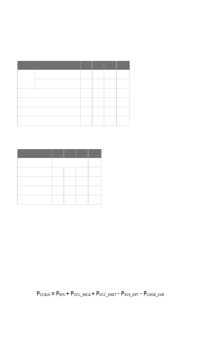
Module specifications Electrical specifications
ConnectCore® 6UL Hardware Reference Manual 116
Electrical specifications
The following tables detail the power supply voltages of the ConnectCore 6UL module.
With front-end LDO
Power domain Min Typ Max Unit
VPWR In regulation 4.6 - 5.5 V
In dropout operation 3.7 - 4.6 V
VSYS 4.3 4.4 4.55 V
VSYS2 2.8 - 4.5 V
VCC_LICELL 2.4 3 3.6 V
VCC_MCA 2.4 3 3.6 V
Without front-end LDO
Power domain Min Typ Max Unit
VPWR 0 V
VSYS 3.7 4.4 4.5 V
VSYS2 2.8 4.4 4.5 V
VCC_LICELL 2.4 3 3.6 V
VCC_MCA 2.4 3 3.6 V
Power consumption
This section contains data on the power consumption of the ConnectCore 6UL module using
measurements from the following power domains:
nVSYS: the input power rail of the module (PMIC input). Power consumption associated with
other power domains that power carrier board peripherals (3V3_EXT and LDO4_1V8) will be
discounted from the values since they are powering external circuitry. However, the VCC_ENET
power domain (which is powered externally) as well as VCC_MCA (which is powering the on-
module MCA) are included the module power consumption. So, the global power consumption
of the ConnectCore 6UL module is calculated as:
nVCC_MCA: input power rail of the on-module MCA. While this power consumption is part of the
module, its input is different than the PMIC (VSYS) so it is measured separately. It's important
Module specifications Power consumption
ConnectCore® 6UL Hardware Reference Manual 117
to note that the MCA power consumption is very stable in run-time and fluctuates very little
from one use case to another. So, for this element, only three use cases are represented:
suspend to RAM, power-off, and run-time.
Note These power consumption numbers should be considered guidelines only, never as fixed or
absolute values. Actual values will depend entirely upon individual setup and system application.
Note The wireless tests were run with the device in test mode. Since in test mode the system is
configured to work at 99% time transmitting, these values can be considered to be the highest power
consumption associated with each wireless mode. In real wireless transmission, many modes and
modulations may be used in a single connection depending on the environmental conditions, resulting
in different power consumption numbers. See Power consumption: Real wireless transmission.
Power consumption use cases
This section describes the use cases that were used to measure power consumption of the
ConnectCore 6UL module.
Suspend
System in suspend-to-RAM mode. The power consumption in this operation mode will be evaluated
when using and not using the PMIC Front-end LDO. See Power supply for more information about how
to power up the ConnectCore 6UL module.
CAUTION! You can achieve minimum power consumption numbers by disabling both
3.3V power domains. However, in some applications it may not be possible to switch
them off, depending on what they are powering.
Power-off
System in power-off with RTC enabled. RTC is running in the MCA. The power consumption in this
operation mode will be also evaluated when using and not using the PMIC Front-end LDO.
IDLE
System up and running. Ethernet and wireless disabled.
Decoding video
System up and running with the following configuration:
nEthernet and wireless disabled.
nFusion7 parallel display connected to the system.
Includes two different use cases:
nDisplay connected in IDLE mode (without decoding video).
nCPU decoding video.
CPU stress
System up and running with the following configuration:

Module specifications Power consumption
ConnectCore® 6UL Hardware Reference Manual 118
nOne Ethernet interface up and linked. The other one disabled.
nUSB connected to the system.
nHanoi application running. (The Hanoi application stresses the CPU and put it at 100% work
load.)
Wireless
In all other use cases, wireless was disabled in order to ease the power consumption calculation. This
dedicated section describes the power consumption of the ConnectCore 6UL modulewhen
transmitting (in test mode) in different wireless modes on both 2.4 GHz and 5 GHz channels (see
Power consumption: Real wireless transmission):
2.4 GHz:
n99% time transmitting.
nChannel 6 (2437 MHz).
5 GHz:
n99% time transmitting.
nChannel 120 (5600 MHz).
In the real wireless transmission scenario, the ConnectCore 6UL module is connected to an AP
(transmitting and receiving):
nEthernet disabled.
n50MB file transmitted and received between the DUT and the AP.
nConnection in the 802.11g/n mode at 2.4 GHz (2437 MHz channel).
nIn a real wireless transmission, modulation and bandwidth are configured automatically.
Wireless UART Bridge
Hardware setup
nConnectCore 6UL module mounted on a SBCExpress.
nUART4 connected to a host PC serial port (through a TTL-to-RS232 adapter).
nConsole connected to the host PC.
Test case configuration
nContinuous traffic through the UART4, commanded through the Console port (stressing both
UARTs):
lChecks all bit rates below 115200.
lChecks different parities and packet sizes.
nWireless up and running:
l100 K file transmitted and received between the DUT and the AP, so there will be also
reception through the wireless interface. The test is continuously sending the packages, so
more than one transmission is executed every five seconds.
lConnection in the 802.11g/n mode at 2.4 GHz (2437 MHz channel).
nI2C1 bus up and running (no specific actions taken on this interface).

Module specifications Power consumption
ConnectCore® 6UL Hardware Reference Manual 119
The power consumption contribution of the serial buses, as the I2C or the UART, is negligible
compared to the wireless or a high CPU load (such as decoding video or executing dedicated
computational applications). See Power consumption: Wireless-UART bridge.
Power consumption debugging
You can use the ConnectCore 6UL SBC Express to simplify the design and debugging of optimized
power consumption for the ConnectCore 6UL module. Specific current measurement options have
been added for measuring VSYS and VCC_MCA going to the ConnectCore 6ULmodule. To use the
current measurement option on VSYS, depopulate R113 and populate J15. Connect a multimeter
across J15 to measure VSYS current flowing to the module. You can apply a similar procedure to R114
and J16 to measure VCC_MCA current.
You can also use the ConnectCore 6UL SBC Express to test VSYS supplies below 4.5V, which are
typically required for battery operation. In order to facilitate this mode, ground VPWR (R115 populated
and R6 depopulated) and leave LDOG unconnected (depopulate C1 and U1). To connect the power
connector J3 to VSYS, populate R116. In this configuration, the module must be supplied by a voltage
between 4.5V and 3.7V. The lower limit of 3.7V is mandatory for maintaining a 3.3V output on the buck
converters of the PMIC.
Note The 3.7V lower limit only applies to VSYS and not VSYS2 on a battery-operated design, since
VSYS2 is supplying only buck converters with much lower output voltage. In this configuration, you can
connect a battery directly to VSYS2 as long as you have a buck boost regulator for VSYS. While this
mode of operation is supported by the ConnectCore 6UL module, the ConnectCore 6UL SBC Express
does not provide options to test/evaluate it.
Global power consumption
The following tables list the global power consumption of the ConnectCore 6UL module when the
system is under the use cases described below.
Suspend and power-off modes
Suspend-to-RAM mode Power-off mode
Front-end LDO
used (VSYS = 4.4V)
Front-end LDO not
used (VSYS = 3.8V)
Front-end LDO
used (VSYS = 4.4V)
No Front-end LDO
used (VSYS = 3.8V)
Whole
module
17.8 mW 8.55 mW 1.65 mW* 1.32 mW*
MCA 12 uW 7.5 uW
Note * See Power supply for detailed information about how to optimize the power consumption in
low power modes.
Module specifications Power consumption
ConnectCore® 6UL Hardware Reference Manual 120
Run-time modes
Run-time
IDLE Display connected (IDLE) Decoding video CPU stress
Whole module 0.635 W 0.649 W 0.868 W 0.840 W
MCA 20 mW
Note These power consumption numbers should be considered guidelines only, never as fixed or
absolute values. Actual values will depend entirely upon individual setup and system application.
Power consumption: Wireless power consumption increase
The following tables shows the power consumption increase of the ConnectCore 6UL module when
transmitting in 2.4 GHz and 5 GHz modes:
2.4 GHz modes Power (dBm) Continuous Tx (99%)
11b 1 Mbps 20MHz 18 1.123 W
11b 11 Mbps20MHz 18 1.086 W
11g 6 Mbps20MHz 18 0.991 W
11g 54 Mbps20MHz 18 0.783 W
11g/n MCS020MHz 18 0.976 W
11g/n MCS720MHz 15 0.643 W
11g/n MCS0 40MHz 17 0.932 W
11g/n MCS7 40MHz 15 0.552 W
5 GHz modes Power (dBm) Continuous Tx (99%)
11a 6 Mbps20MHz 13 1.095 W
11a 54 Mbps20MHz 11 0.801 W
11a/n MCS020MHz 13 1.083 W
11a/n MCS720MHz 10 0.743 W
11a/n MCS0 40MHz 12 1.052 W
11a/n MCS7 40MHz 9 0.636 W
11ac MCS020MHz 13 1.097 W
11ac MCS720MHz 10 0.712 W
11ac MCS820MHz 9 0.672 W
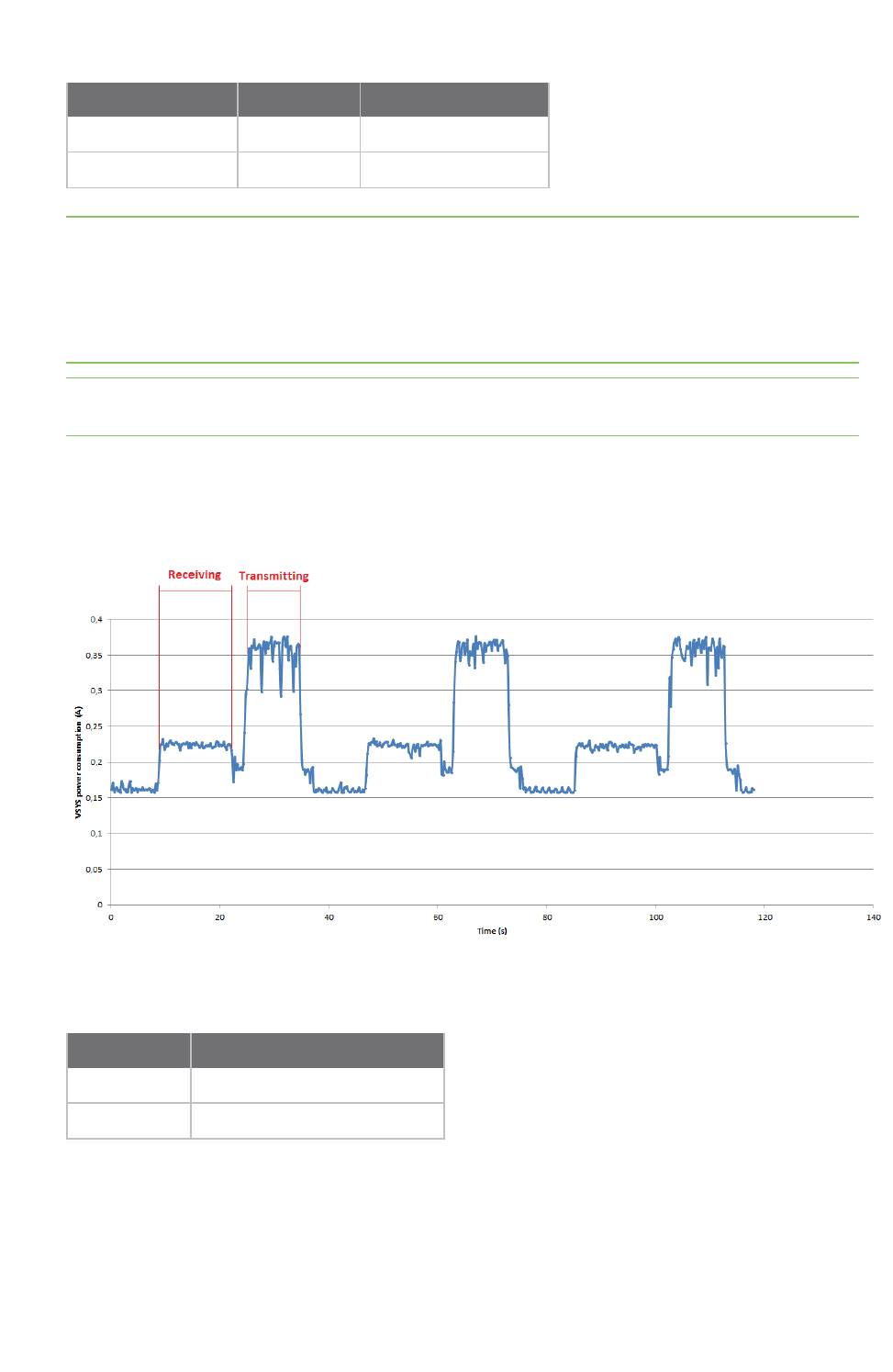
Module specifications Power consumption
ConnectCore® 6UL Hardware Reference Manual 121
5 GHz modes Power (dBm) Continuous Tx (99%)
11ac MCS9 40MHz 7 0.540 W
11ac MCS9 80MHz 6 0.467 W
Note Continuous Rx
Continuously receiving data (continuous Rx) in test mode has almost no effect on the power
consumption of the module. In real transmissions, there won't be a continuous reception use case
because the system will be always transmitting some synchronization data when receiving, and the
power consumption will be increased as observed in Power consumption: Real wireless transmission
(but never as much as when transmitting).
Note These power consumption numbers should be considered guidelines only, never as fixed or
absolute values. Actual values will depend entirely upon individual setup and system application.
Power consumption: Real wireless transmission
The following plot shows the power consumption of the ConnectCore 6UL VSYS power domain during
a real wireless transmission:
The power consumption increase of the real wireless transmission is calculated by taking the mean
power consumption value of the transmission and receiver bursts:
Power consumption increase
Transmission 0.849 W
Reception 0.279 W
As expected, the transmission power consumption is lower than the maximum observed in the tables
above on the 802.11g/n mode (0.976 W in 11g/n MCS0 20MHz). In a real wireless transmission,
modulation and bandwidth are configured automatically.
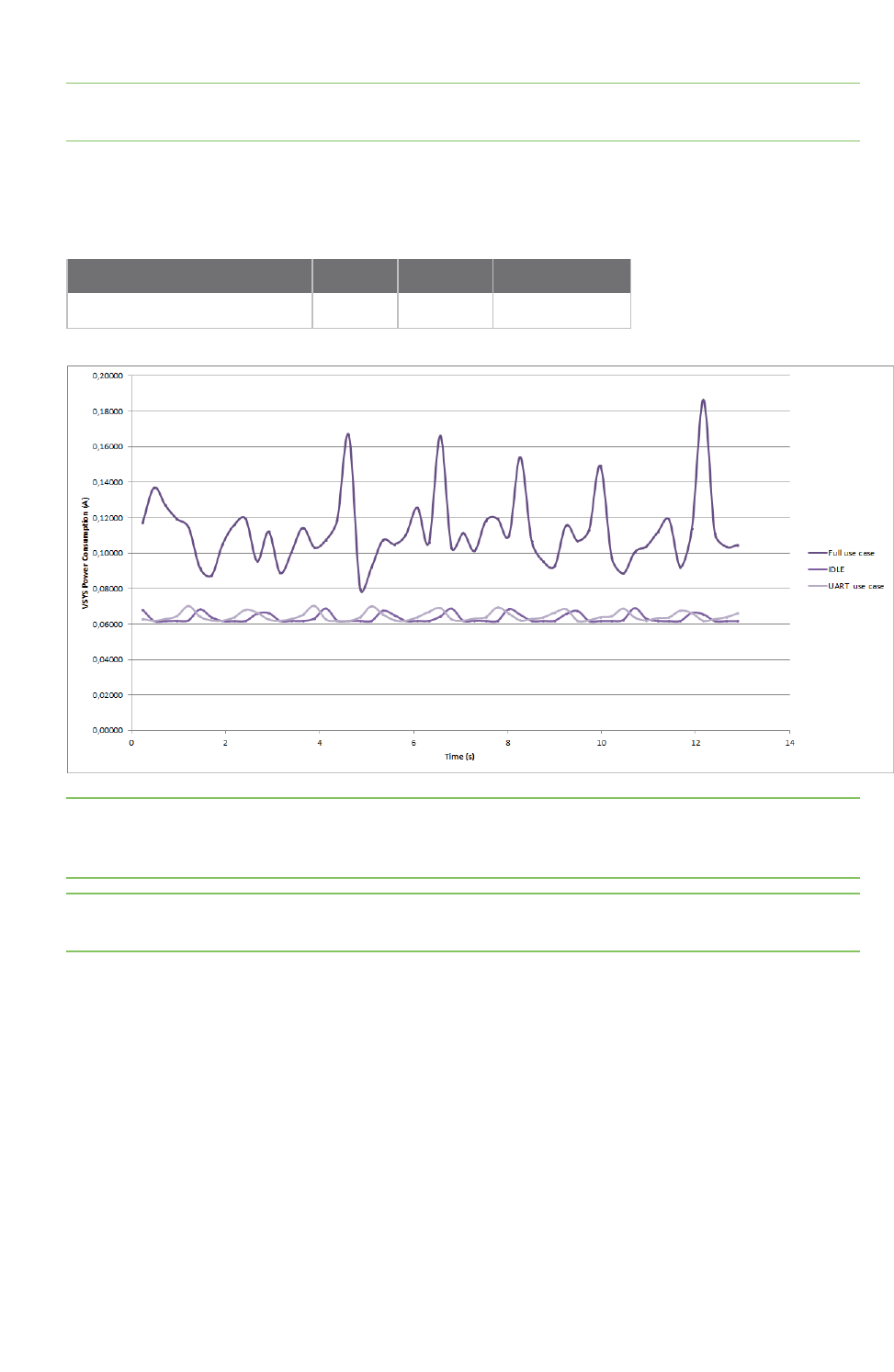
Module specifications Mechanical specifications
ConnectCore® 6UL Hardware Reference Manual 122
Note These power consumption numbers should be considered guidelines only, never as fixed or
absolute values. Actual values will depend entirely upon individual setup and system application.
Power consumption: Wireless-UART bridge
The following table shows average power consumption of each operating mode:
IDLE UART UART+Wireless
Module power consumption 0.3011 W 0.30589 W 0.524 W
Note Average power consumption was calculated after approximately a minute of sampling data, but
the plot shows power consumption over 13 seconds for a more detailed view of power consumption
oscillations.
Note These power consumption numbers should be considered guidelines only, never as fixed or
absolute values. Actual values will depend entirely upon individual setup and system application.
Mechanical specifications
This section provides mechanical dimensions and host PCB footprint guidance for the Digi SMTplus™
(patent-pending) form factor of the ConnectCore 6UL module.
Dimensions
Note that all dimensions are in millimeters.
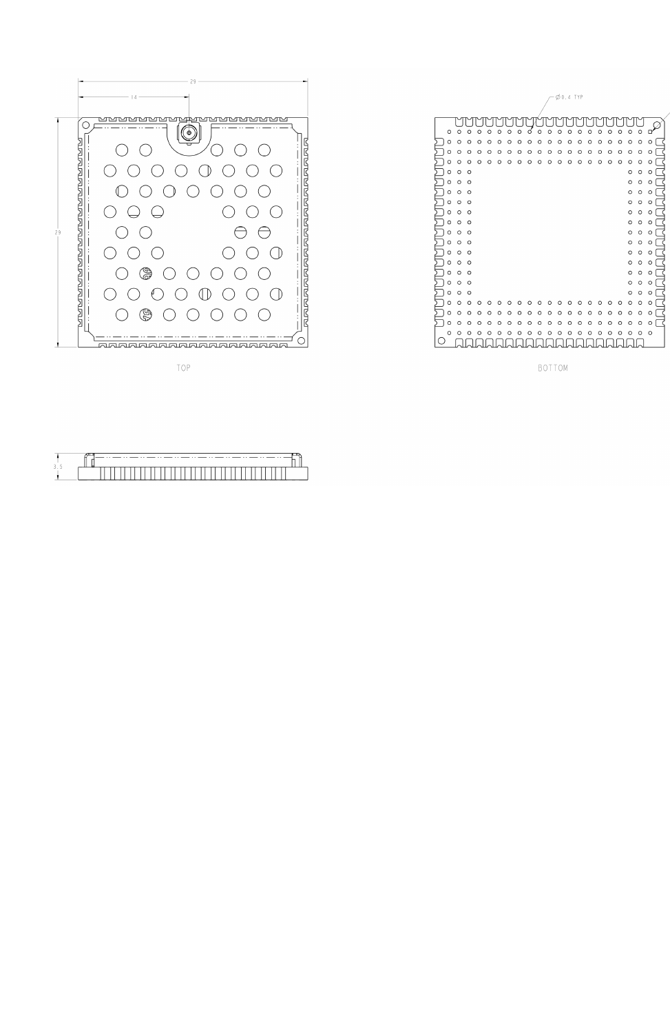
Module specifications Mechanical specifications
ConnectCore® 6UL Hardware Reference Manual 123
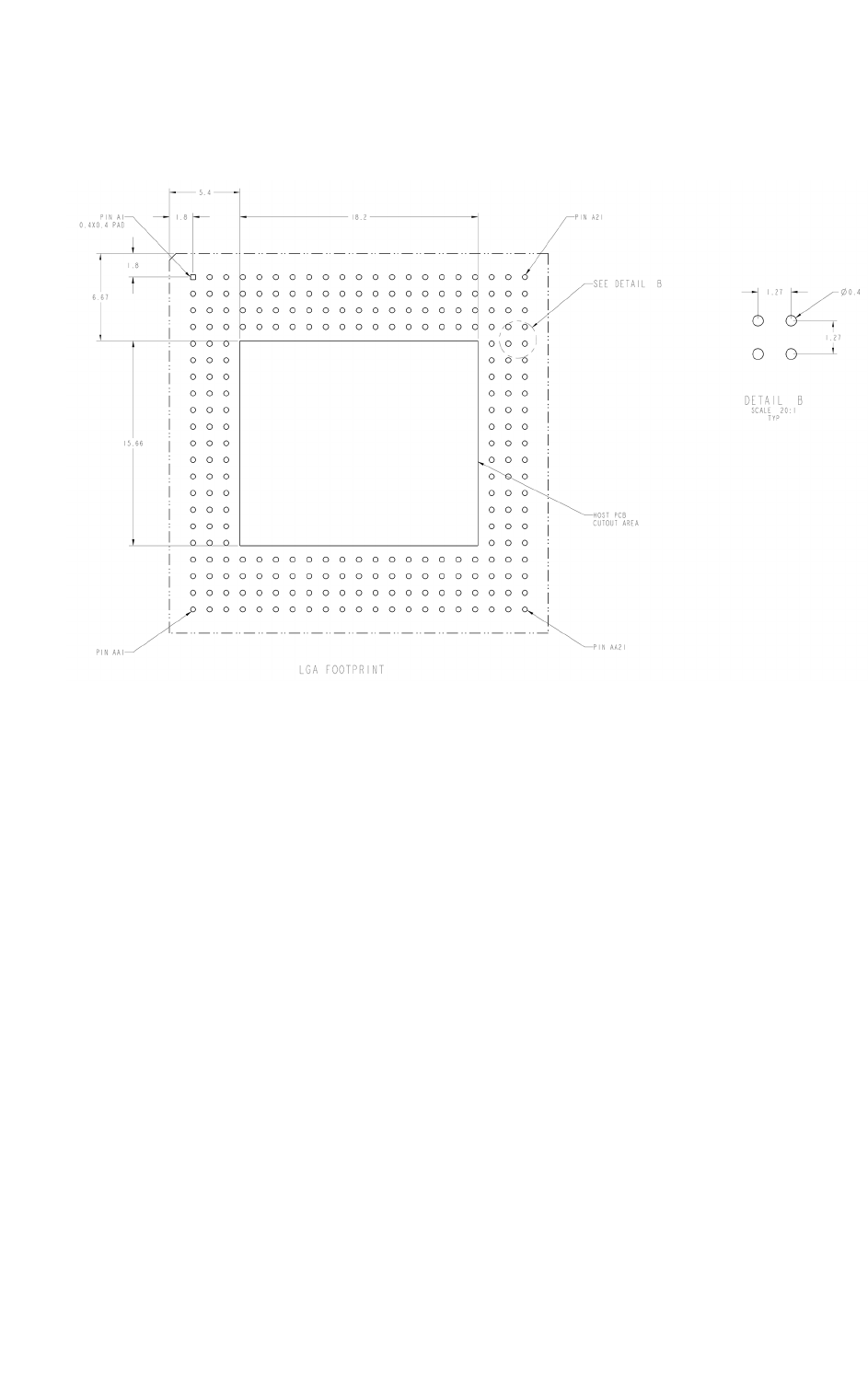
Module specifications Mechanical specifications
ConnectCore® 6UL Hardware Reference Manual 124
Host PCB footprint
Digi SMTplus™ LGA mounting
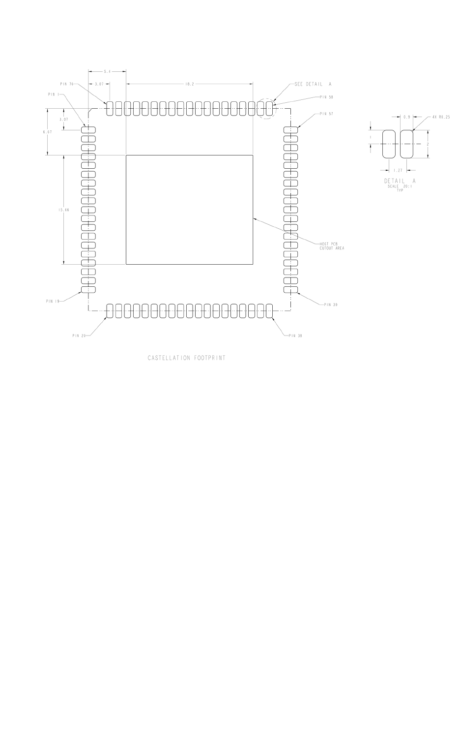
Module specifications Environmental specifications
ConnectCore® 6UL Hardware Reference Manual 125
Digi SMTplus™ Castellated Edge Via mounting
Weight
The weight of the ConnectCore 6UL module (with Wi-Fi/BT networking and shield) is 6.45g.
Environmental specifications
nOperating temperature: -40 to 85C.
nThe ConnectCore 6UL module shall be built in an enclosure so that the shield is not accessible
to the end-user.
Socket options
For testing, prototyping, and other primarily development-related purposes, Digi International and E-
tec Interconnect AG have developed sockets allowing the easy insertion and removal of modules in a
carrier board design. Socket models for both LGA and castellated via use cases are available.
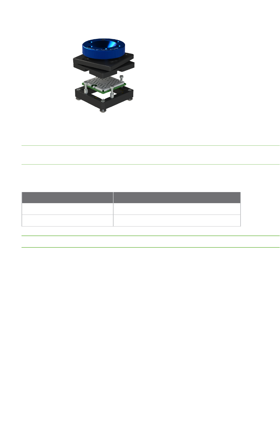
Module specifications Socket options
ConnectCore® 6UL Hardware Reference Manual 126
All drawings, user instructions, schematics, and PCB footprints are posted on the ConnectCore 6UL
technical support website.
Note The ConnectCore 6UL SBC Express (Digi P/N CC-WMX6UL-START) has been designed to support
a LPF076-1290-19AB55L socket, and can be used as a reference design.
All sockets are sold and built by E-tec Interconnect AG (www.e-tec.com). The table below provides an
overview of the available part numbers.
Socket model E-tec part number
ConnectCore 6UL Castellated Vias LPF076-1290-19AB55L
ConnectCore 6UL LGA LPF245-1270-21AB55A + MGS245-SB01-21A9512
Note Please direct all socket-related purchase inquiries to E-tec Interconnect AG (info@e-tec.com).

Assembly instructions
Moisture sensitivity and shelf life 128
Mounting 128
Solder paste print 128
Stencil 128
Coplanarity 128
SMT pick and place 129
SMT process parameter reference - for both castellation and LGA applications 129
Reflow profiles using a ten-zone oven, SAC 305 lead-free solder paste (Alpha OM-340) 129
Vapor Phase Profile Recommendation Using IBL 309 Batch Soldering Machine, SAC 305 Lead-Free
Solder Paste (Alpha OM-340) 130
Vapor Phase IBL 309 batch soldering machine settings 132
Conformal coating 132
ConnectCore® 6UL Hardware Reference Manual 127

Assembly instructions Moisture sensitivity and shelf life
ConnectCore® 6UL Hardware Reference Manual 128
Moisture sensitivity and shelf life
1. The ConnectCore 6UL module is classified as a Level 3 Moisture Sensitive Device in accordance
with IPC/JEDEC J-STD-020.
2. Calculated shelf life in sealed packaging: 12 months at <40°C and <90% relative humidity (RH).
3. Environmental condition during production: 30°C /60% RH according to IPC/JEDEC J-STD -033C,
paragraph 5.
4. Maximum time between opening of the sealed packaging and reflow process must not exceed
168 hours, based on condition b), IPC/JEDEC J-STD -033C, paragraph 5.2.
5. Baking is required, if conditions b) or c) do not apply. See above.
6. Baking is required, if the packaging humidity indicator indicates 10% RH or higher.
7. If baking is required, bake modules in trays 4-6 hours at 125°C; maximum stacking height is 10
trays.
Mounting
The ConnectCore 6UL module has been designed with easy integration into existing SMT processes in
mind. This section contains guidance for mounting the module on your carrier board.
The module can be configured and mounted in a Castellation OR Land Grid Array (LGA) form.
Modules are also not sealed and therefore they should not be subjected to a wash cycle or similar
treatment where condensation could occur. Contact Digi International for additional guidance to
discuss conformal coating approaches and options, if needed. The module is built with a No-Clean flux
solder paste. The module is provided to the user clean.
The following solder paste type has been approved for mounting the module on a carrier board:
nSAC305 (Lead-free: Alpha OM-340 Type 4 or equivalent). This is a No-Clean Flux solder paste.
Solder paste print
The following solder paste printing parameters are recommended:
nStencil thickness: 0.100 mm / 4 mil
nStencil diameter: One to one of pad diameter (to +20% of pad)
nPaste alignment: 20% off the pad max (offset <20% pad diameter)
Stencil
For both castellation AND LGA applications, Digi recommends you use a laser cut and/or electro-
formed stencil for placing the ConnectCore 6UL module. Based on the actual coplanarity
characteristics of your carrier board, adjustments may be required to determine the optimal solder
paste volume. It is also recommended to perform an X-ray analysis of the initial production run of your
assembly with the ConnectCore 6UL module. Please contact Digi for additional support.
Coplanarity
The coplanarity measured on the ConnectCore 6UL module is <0.003" bow and twist (98% confidence
interval). It is important that the carrier board is also coplanar. If the carrier board is thinner than the

Assembly instructions SMT pick and place
ConnectCore® 6UL Hardware Reference Manual 129
ConnectCore 6UL module it is recommended that the assembly be supported during the reflow
process, i.e. reflow fixture should be used to minimize the potential bow of the carrier card.
SMT pick and place
nPlacement nozzle: Largest available on the machine.
nNozzle Pick Surface: Center of shield on i.MX6UL SoM.
nPlacement Speed: Slowest speed for the machine.
nPlacement alignment: 10% of pad diameter (compensating for module weight and supporting
alignment). The module should be placed last as part of the assembly/mounting process to
eliminate unexpected shifting.
SMT process parameter reference - for both castellation and LGA
applications
Process SMT process Specification recommendations
Screen
Print
Solder paste SAC 305 No-Clean (Alpha OM-340 or
equivalent)
Stencil thickness 0.100mm / 4mil
Recommended aperture size 0.55mm / 22mil rounded square (LGA)
1:1 with pad (castellation)
Paste alignment 20% maximum off center of the pad
PnP Placement nozzle Largest available on machine
Nozzle pick surface Shield center
Speed Slowest possible with PnP machine
Placement sequence Last, if possible
Placement alignment 10% maximum off center of pad
Reflow See Reflow profiles using a ten-zone oven, SAC 305 lead-free solder paste (Alpha OM-
340) .
Reflow profiles using a ten-zone oven, SAC 305 lead-free solder
paste (Alpha OM-340)
nRecommend to keep SOM below 238°C during the reflow cycle for castellation AND LGA
applications
nTime Above Liquidous (TAL) is recommended to be between 56 to 63 seconds.
nUse of 40AWG K-type thermocouple and M.O.L.E or equivalent thermal profiler is
recommended.
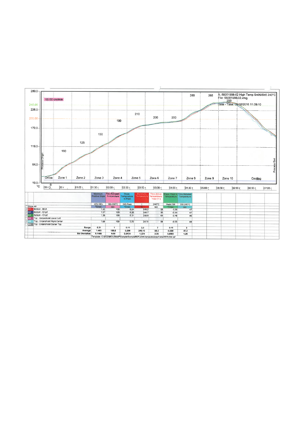
Assembly
instructions
Vapor Phase Profile Recommendation Using IBL 309 Batch Soldering Machine, SAC 305 Lead-
Free Solder Paste (Alpha OM-340)
ConnectCore® 6UL Hardware Reference Manual 130
nFor castellation applications, only one thermal couple is required. Digi recommends it is located
on a ground pad castellation.
nFor LGA applications, two thermocouples should be used: one located on the outer-most row
and a second located near the underside center of the SOM to ensure SOM is not exposed to
excessive temperatures.
The following image shows the reflow profile based on a ten-zone convection oven.
The reflow profile shown above is valid for the combination solder paste/reflow machine and Digi
reference carrier board. Optimization of a reflow profile will depend on the selected solder
paste/reflow machine (reflow or vapor phase) and carrier board design.
The ConnectCore 6UL module is approved to withstand a total of four (4) reflow cycles. Two (2) reflow
cycles are required for manufacturing the ConnectCore 6UL module. Two (2) reflow cycles are
remaining for mounting the module on the carrier board. Digi strongly recommends soldering the
ConnectCore 6UL module during the last reflow cycles of the carrier board manufacturing process.
Vapor Phase Profile Recommendation Using IBL 309 Batch
Soldering Machine, SAC 305 Lead-Free Solder Paste (Alpha OM-
340)
nRecommend to keep SOM below 235°C during the reflow cycle for castellation AND LGA
applications:
lThis is controlled by the Solvay Plastics, Galden XS230 vapor fluid; maximum soldering
temperature 230C for unleaded solder.
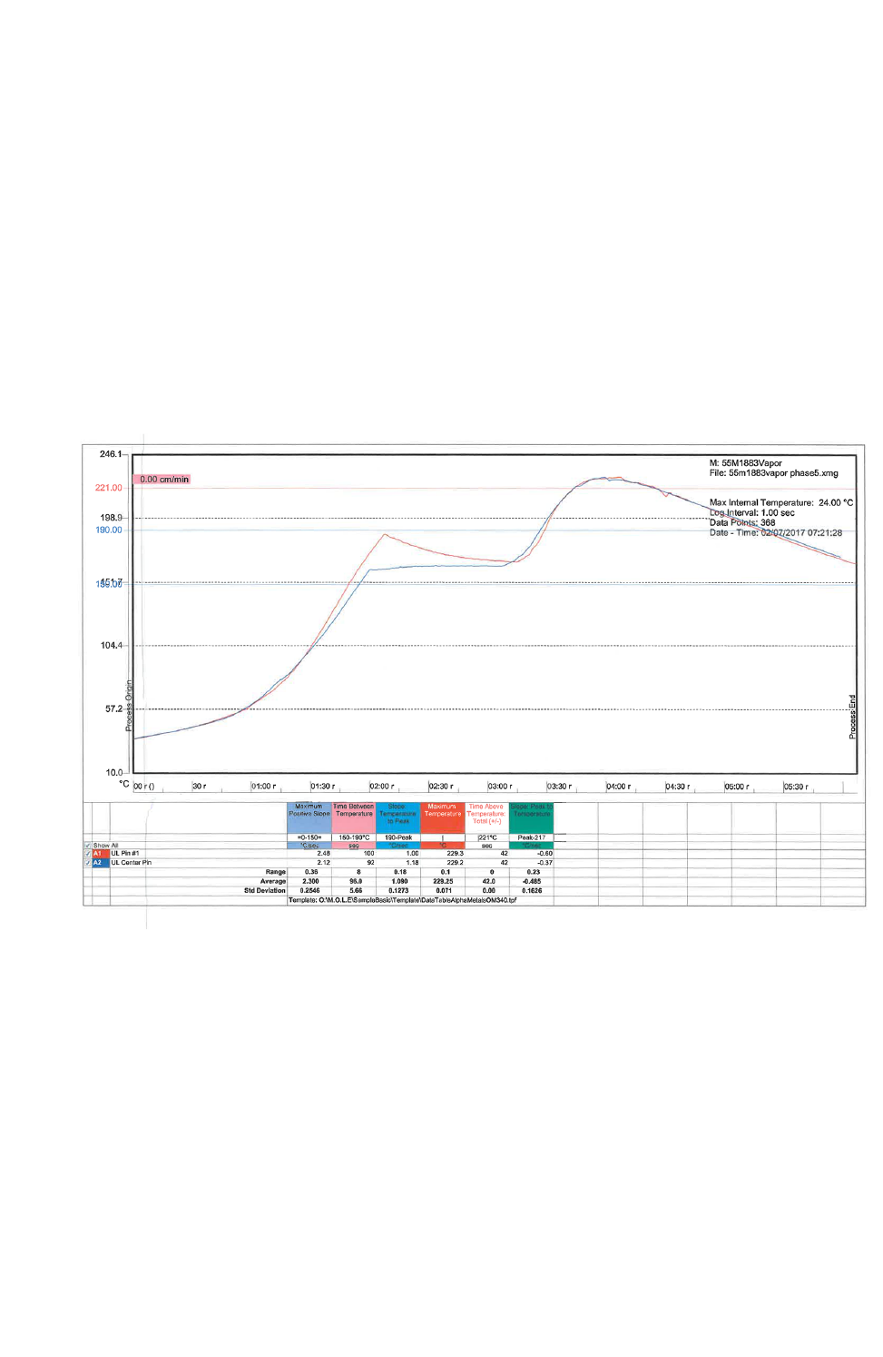
Assembly
instructions
Vapor Phase Profile Recommendation Using IBL 309 Batch Soldering Machine, SAC 305 Lead-
Free Solder Paste (Alpha OM-340)
ConnectCore® 6UL Hardware Reference Manual 131
nVapor Phase heat transfers faster than reflow meaning Time Above Liquidous (TAL) is shorter.
Digi recommends TAL to be between 40 and 45 seconds.
nUse of 40AWG K-type thermocouple and M.O.L.E or equivalent thermal profiler is
recommended.
nFor castellation applications, only one thermal couple is required recommended to be location
on a ground pad castellation.
nFor LGA applications, two thermocouples should be used. One located on the outer most row
and a second location should be near the underside center of the SoM to ensure SoM is not
exposed to excessive temperatures
nSolder Pallet shall be used that can be processed through screen print, Pick & Place and vapor
phase.
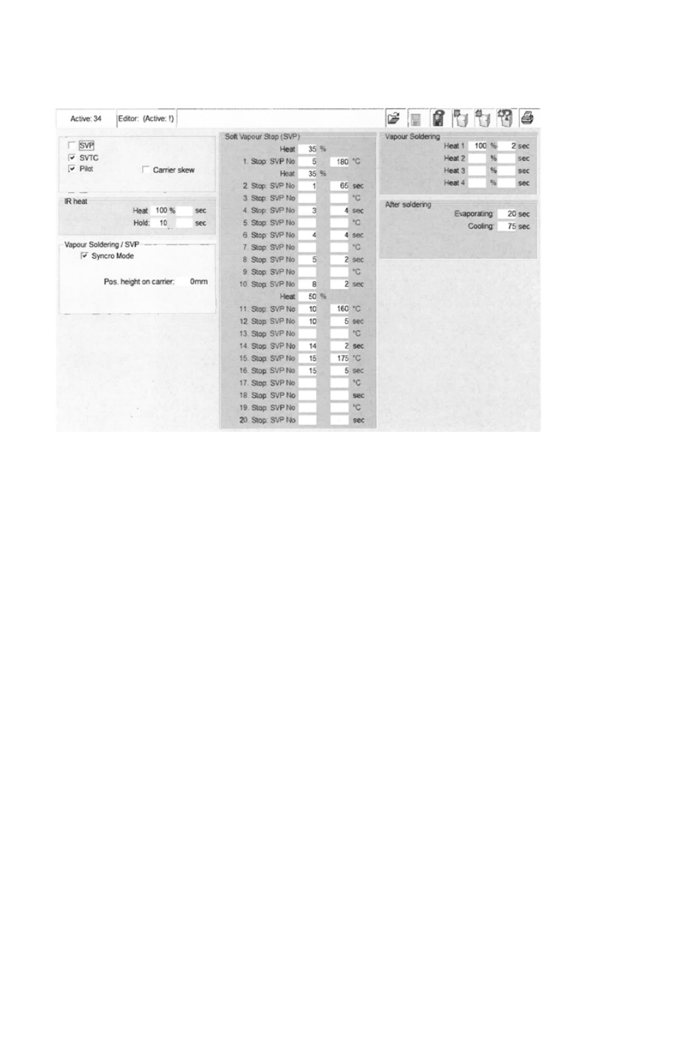
Assembly instructions Vapor Phase IBL 309 batch soldering machine settings
ConnectCore® 6UL Hardware Reference Manual 132
Vapor Phase IBL 309 batch soldering machine settings
Conformal coating
The ConnectCore 6UL module may be conformally coated using an IPC-CC-830 compliant Acrylic (Type
AR) coating material. The material shall be applied by spray application IPC-A-610. DIP coating is
method shall not be used. If other coating material is required Urethane (Type UR), Silicone (Type SR)
or Epoxy (Type ER) please contact Digi.


Certifications External antenna
ConnectCore® 6UL Hardware Reference Manual 134
External antenna
In order to reuse the FCC and IC modular approval of the ConnectCore 6UL module when using the
external antenna connected to pad B13 (RF_ANT_EXT), the exact same circuitry as in the schematics
and PCB routing of the ConnectCore 6UL SBC PRO must be used. Exact routing information can be
found on the product support page in the section Design Documents / ConnectCore 6UL SBC Project
(ALTIUM). In this document, you can find the corresponding PCB material used, trace width and length.
United States FCC
The ConnectCore 6UL module complies with Part 15 of the FCC rules and regulations. Compliance
with the labeling requirements, FCC notices and antenna usage guidelines is required. To fulfill FCC
Certification, the OEM must comply with the following regulations:
The system integrator must ensure that the text on top side of the module is placed on the outside of
the final product.
ConnectCore 6UL module may only be used with antennas approved. See FCC-approved antennas.
WARNING! The Original Equipment Manufacturer (OEM) must ensure that FCC labeling
requirements are met. This includes a clearly visible label on the outside of the final
product enclosure that displays the contents shown below. Required FCC Label for OEM
products containing the ConnectCore 6UL module.
Contains FCC ID: MCQ-CCIMX6UL
This device complies with part 15 of the FCC Rules. Operation is subject to the following two
conditions: (1) This device may not cause harmful interference, and (2) this device must accept any
interference received, including interference that may cause undesired operation.
FCC notices
IMPORTANT: The ConnectCore 6UL module has been certified by the FCC for use with other products
without any further certification (as per FCC section 2.1091). Modifications not expressly approved by
Digi could void the user's authority to operate the equipment.
IMPORTANT: OEMs must test final product to comply with unintentional radiators (FCC section 15.107
& 15.109) before declaring compliance of their final product to Part 15 of the FCC Rules.
IMPORTANT: The ConnectCore 6UL module has been certified for remote and base radio applications.
If the module will be used for portable applications, the device must undergo SAR testing. This
equipment has been tested and found to comply with the limits for a Class B digital device, pursuant
to Part 15 of the FCC Rules. These limits are designed to provide reasonable protection against
harmful interference in a residential installation. This equipment generates uses and can radiate radio
frequency energy, and if not installed and used in accordance with the instructions, may cause harmful
interference to radio communications. However, there is no guarantee that interference will not occur
in a particular installation. If this equipment does cause harmful interference to radio or television
reception, which can be determined by turning the equipment off and on, the user is encouraged to try
to correct the interference by one or more of the following measures: Re-orient or relocate the
receiving antenna, Increase the separation between the equipment and receiver, Connect equipment
and receiver to outlets on different circuits, or Consult the dealer or an experienced radio/TV
technician for help.
IMPORTANT: ConnectCore 6UL module is for professional (OEM) installation only.
Certifications United States FCC
ConnectCore® 6UL Hardware Reference Manual 135
FCC-approved antennas
The ConnectCore 6UL module can be installed utilizing antennas and cables constructed with non-
standard connectors (RPSMA, RPTNC, and so on).
The modules are FCC approved for fixed base station and mobile applications for the channels
indicated in the tables below. If the antenna is mounted at least 20cm (8 in.) from nearby persons, the
application is considered a mobile application. Antennas not listed in the table must be tested to
comply with FCC Section 15.203 (Unique Antenna Connectors) and Section 15.247 (Emissions).
The antennas in the tables below have been approved for use with this module. Digi does not carry all
of these antenna variants. Contact Digi Sales for available antennas.
Antennas approved for use with the ConnectCore 6UL Wi-Fi modules
Part number Type (description)
Peak gain
2.4 GHz
Peak gain
5 GHz
Linx Technologies Inc. ANT-
DB1-RAF-RPS
Dipole, articulated RPSMA, dual band
2.4 GHz & 5 GHz
2.5 4.6
Ethertronics 1001932 PCB antenna, dual band 2.4 GHz & 5
GHz
2.5 4.4
Yageo ANTX100P001B24553 PCB antenna, dual band 2.4 GHz & 5
GHz
4.6 5.1
Note If using the RF module in a portable application (for example - if the module is used in a hand-
held device and the antenna is less than 20cm from the human body when the device is in operation):
The integrator is responsible for passing additional SAR (Specific Absorption Rate) testing based on
FCC rules 2.1091 and FCC Guidelines for Human Exposure to Radio Frequency Electromagnetic Fields,
OET Bulletin and Supplement C. The testing results will be submitted to the FCC for approval prior to
selling the integrated unit. The required SAR testing measures emissions from the module and how
they affect the person.
Note When using Linx Technologies Inc. ANTDB1-RAF-RPS antenna, make sure to use a cable of
minimum 10cm long and of type RG-178.
RF exposure
CAUTION! To satisfy FCC RF exposure requirements for mobile transmitting devices, a
separation distance of 20 cm or more should be maintained between the antenna of this
device and persons during device operation. To ensure compliance, operations at closer
than this distance are not recommended. The antenna used for this transmitter must
not be co-located in conjunction with any other antenna or transmitter. The preceding
statement must be included as a CAUTION statement in OEM product manuals in order
to alert users of FCC RF Exposure compliance.
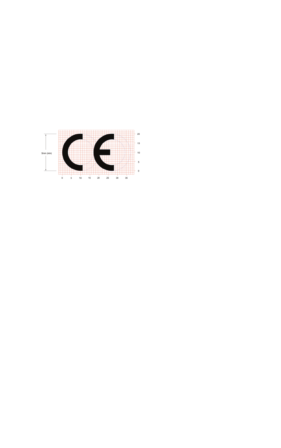
Certifications Europe
ConnectCore® 6UL Hardware Reference Manual 136
Europe
n2.412 to 2.472 GHz; 13 channels
n5.180 to 5.320 GHz; 8 channels
n5.500 to 5.700 GHz, 8 channels (excludes 5.600 to 5.640 GHz)
OEM labeling requirements
The CE marking must be affixed to a visible location on the OEM product.
CE labeling requirements
The CE mark shall consist of the initials CE taking the following form:
nIf the CE marking is reduced or enlarged, the proportions given in the above graduated
drawing must be respected.
nThe CE marking must have a height of at least 5mm except where this is not possible on
account of the nature of the apparatus.
nThe CE marking must be affixed visibly, legibly, and indelibly.
Declarations of Conformity
Digi has issued Declarations of Conformity for the ConnectCore 6UL system-on-module concerning
emissions, EMC, and safety. For more information, see http://www.digi.com/resources/certifications.
Important note
Digi customers assume full responsibility for learning and meeting the required guidelines for each
country in their distribution market. Refer to the radio regulatory agency in the desired countries of
operation for more information.
Approved antennas
The same antennas have been approved for Europe as stated in the FCC table for use with the
ConnectCore 6UL module.
Canada (IC)
IC: 1846A-CCIMX6UL
PMN: CC IMX6UL
HVIN: ConnectCore 6UL

Certifications Canada (IC)
ConnectCore® 6UL Hardware Reference Manual 137
This device complies with Industry Canada license-exempt RSS standard(s). Operation is subject to
the following two conditions: (1) this device may not cause interference, and (2) this device must
accept any interference, including interference that may cause undesired operation of the device.
Le présent appareil est conforme aux CNR d'Industrie Canada applicables aux appareils radio exempts
de licence. L'exploitation est autorisée aux deux conditions suivantes : (1) l'appareil ne doit pas
produire de brouillage, et (2) l'utilisateur de l'appareil doit accepter tout brouillage radioélectrique
subi, même si le brouillage est susceptible d'en compromettre le fonctionnement.
Labeling requirements
Labeling requirements for Industry Canada are similar to those of the FCC. A clearly visible label on
the outside of the final product enclosure must display the following text:
Contains Model ConnectCore™ for i.MX6UL Radio, IC: 1846A-CCIMX6UL
The Product Marketing Name (PMN) of the product is: CC IMX6UL.
Transmitters with detachable antennas
This radio transmitter (IC: 1846A-CCIMX6UL) has been approved by Industry Canada to operate with
the antenna types listed in the table above with the maximum permissible gain and required antenna
impedance for each antenna type indicated. Antenna types not included in this list, having a gain
greater than the maximum gain indicated for that type, are strictly prohibited for use with this device.
Le présent émetteur radio (IC: 1846A-CCIMX6UL) a été approuvé par Industrie Canada pour
fonctionner avec les types d'antenne énumérés ci-dessous et ayant un gain admissible maximal et
l'impédance requise pour chaque type d'antenne. Les types
d'antenne non inclus dans cette liste, ou dont le gain est supérieur au gain maximal indiqué, sont
strictement interdits pour l'exploitation de l'émetteur.
Under Industry Canada regulations, this radio transmitter may only operate using an antenna of a
type and maximum (or lesser) gain approved for the transmitter by Industry Canada. To reduce
potential radio interference to other users, the antenna type and its gain should be so chosen that the
equivalent isotropically radiated power (e.i.r.p.) is not more than that necessary for successful
communication.
Conformément à la réglementation d'Industrie Canada, le présent émetteur radio peut fonctionner
avec une antenne d'un type et d'un gain maximal (ou inférieur) approuvé pour l'émetteur par Industrie
Canada. Dans le but de réduire les risques de brouillage radioélectrique à l'intention des autres
utilisateurs, il faut choisir le type d'antenne et son gain de sorte que la puissance isotrope rayonnée
équivalente (p.i.r.e.) ne dépasse pas l'intensité nécessaire à l'établissement d'une communication
satisfaisante.
ConnectCore 6UL module is for professional (OEM) installation only.
Le module ConnectCore 6UL doit impérativement être installé par un professionnel (OEM).
RF exposure
To satisfy Industry Canada RF exposure requirements, a separation distance of 20 cm or
more should be maintained between the antenna of this device and persons during
device operation.
Pour satisfaire aux exigences d’Industrie Canada concernant l’exposition RF, une
distance égale ou supérieure à 20cm doit être respectée entre les antennes de ce
produit et les personnes se trouvant à proximité.

Certifications Japan
ConnectCore® 6UL Hardware Reference Manual 138
The preceding statement must be included as a CAUTION statement in OEM product manuals
in order to alert users of Industry Canada RF Exposure compliance.
Cette information doit être incluse dans le manuel du produit OEM afin d’alerter les
utilisateurs sur la nécessité de respecter l’exposition RF d’Industrie Canada.
Approved antennas
The same antennas have been approved for Canada as stated in the FCC table for use with the
ConnectCore 6UL module.
Japan
電 波 法 により5GHz帯 は屋 内 使 用 に限 ります。
This device has been granted a designation number by Ministry of Internal Affairs and
Communications according to:
Ordinance concerning Technical Regulations Conformity Certification etc. of Specified Radio
Equipment (特定無線設備の技術基準適合証明等に関する規則).
nArticle 2, Paragraph 1, Item 19, 19-3, 19-3-2 Category: WW, XW, YW
nModel/Name of equipment: ConnectCore 6UL
nRadio label marking:
lR: 202-LSF056
lT: D 17-0014 202
This device should not be modified (otherwise the granted designation number will be invalid).
n2.412 to 2.472 GHz; 13 channels
n5.180 to 5.320 GHz; 8 channels
n5.500 to 5.700 GHz; 11 channels
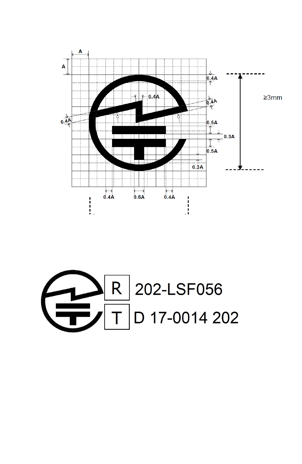
Certifications Japan
ConnectCore® 6UL Hardware Reference Manual 139
Approval Label (MIC Marking)
Label text