Digi S6BSM XBee Wi-Fi S6B SMT Module User Manual XBee Wi Fi RF Modules
Digi International Inc XBee Wi-Fi S6B SMT Module XBee Wi Fi RF Modules
UserManual.wiki
>
Digi
>
S6BSM User Manual
User Manual
Navigation menu
Upload a User Manual
Namespaces
Wiki Guide
HTML
PDF
Info
Views
User Manual
Discussion / Help
Navigation
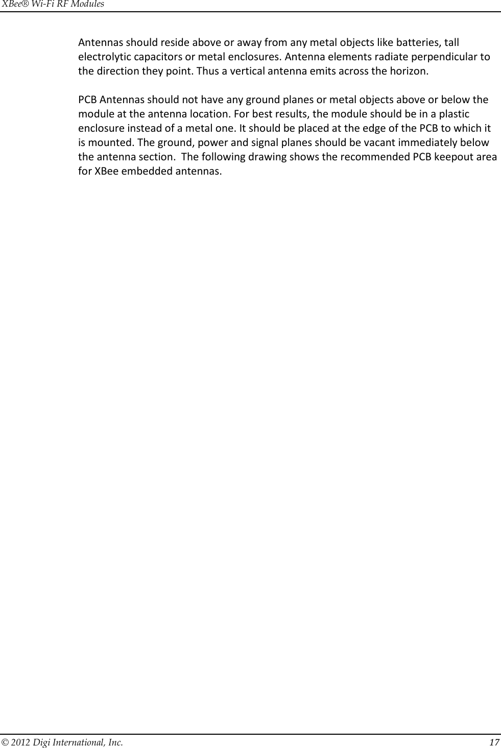
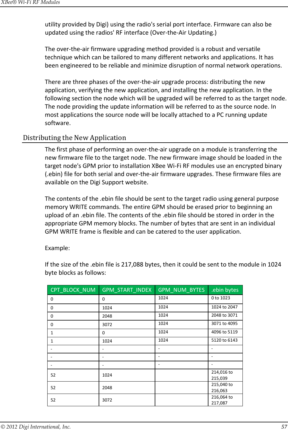
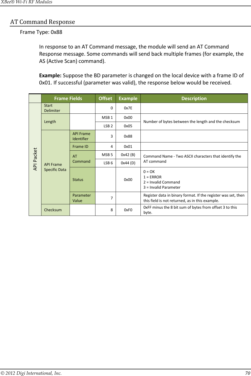
![XBee® Wi-Fi RF Modules © 2012 Digi International, Inc. 2 © 2012 Digi International, Inc. All rights reserved No part of the contents of this manual may be transmitted or reproduced in any form or by any means without the written permission of Digi International, Inc. XBee® is a registered trademark of Digi International, Inc. Technical Support Phone: (866) 765-9885 toll-free U.S.A. & Canada (801) 765-9885 Worldwide 8:00 am - 5:00 pm [U.S. Mountain Time] Online Support: http://www.digi.com/support/eservice/login.jsp Email: rf-experts@digi.com](https://usermanual.wiki/Digi/S6BSM/User-Guide-1866580-Page-2.png)
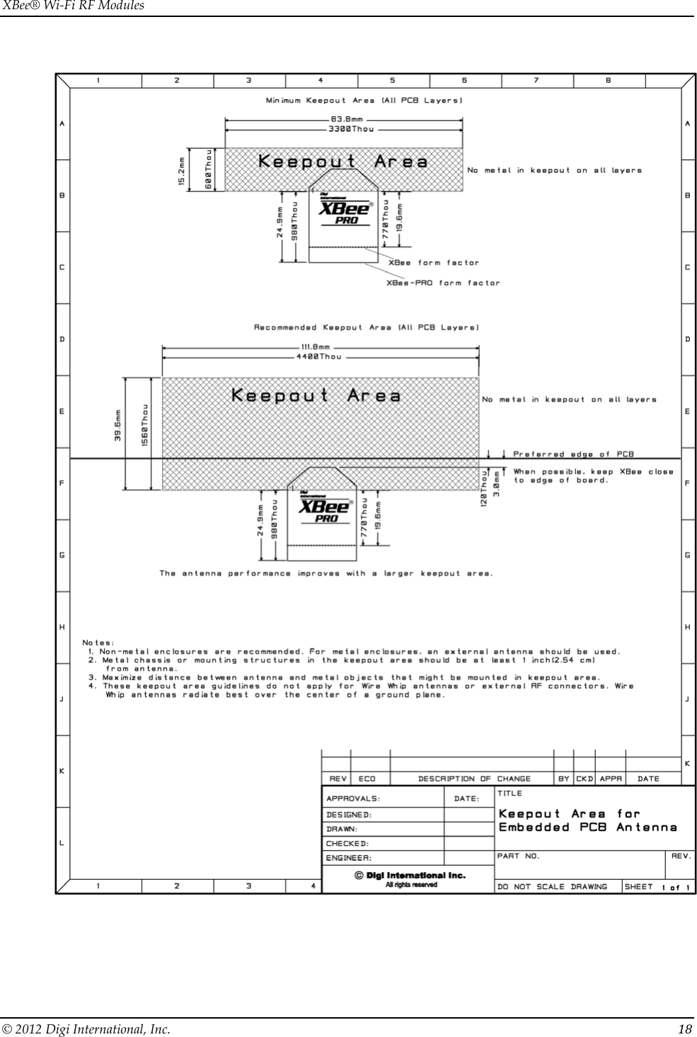
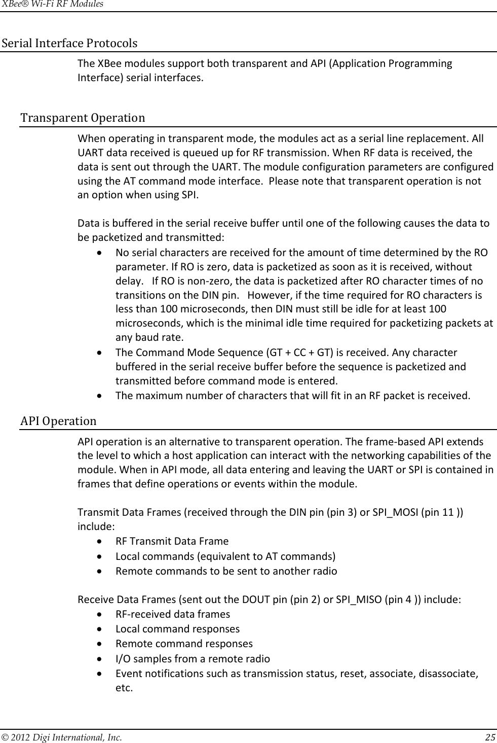
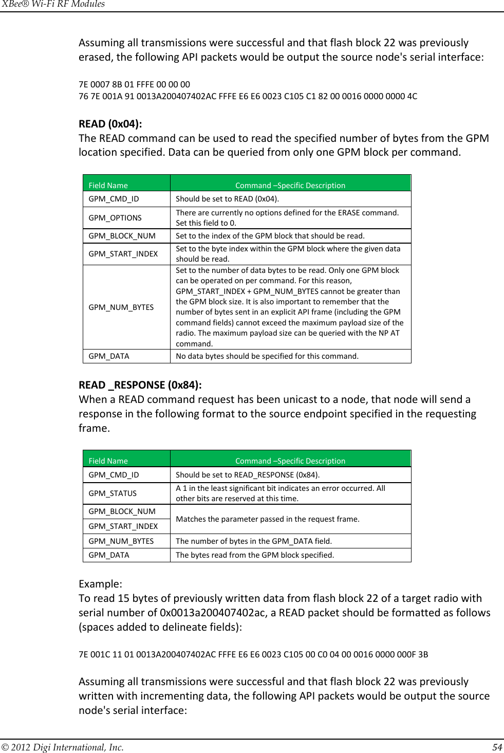
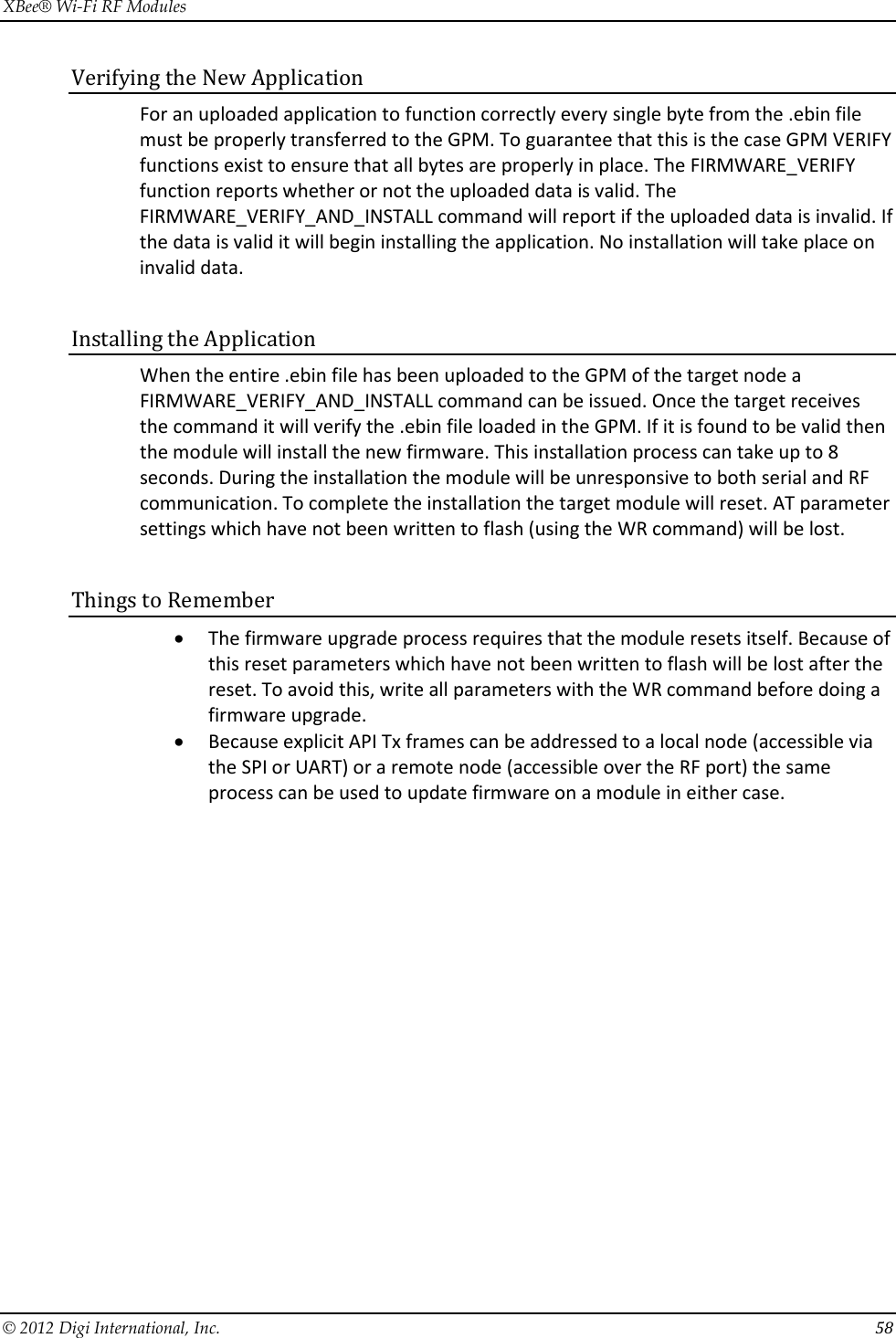
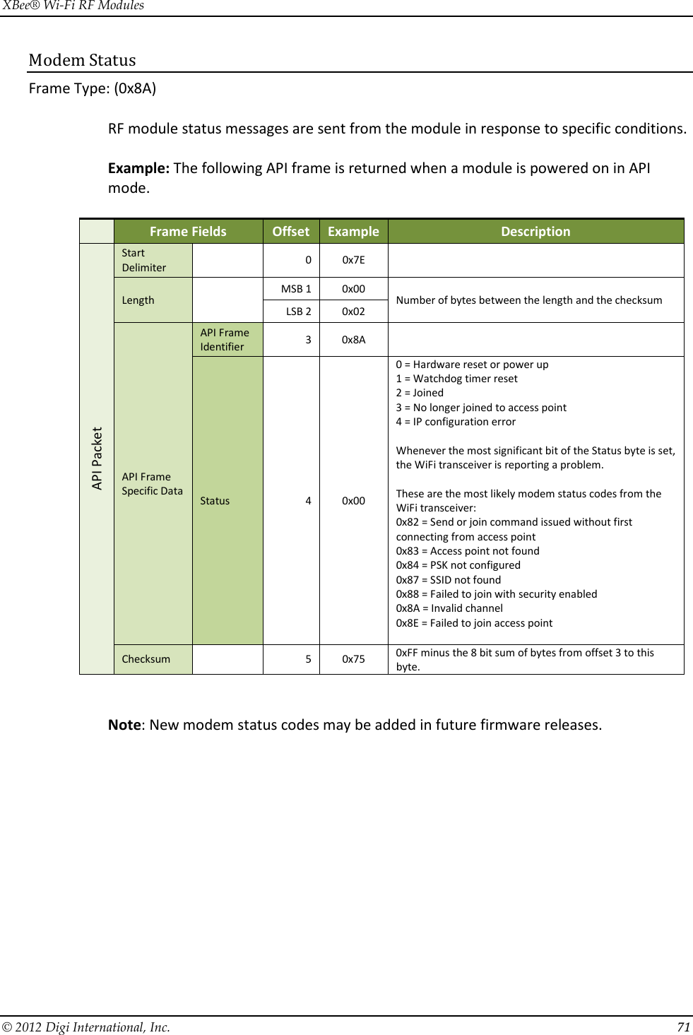
![XBee® Wi-Fi RF Modules © 2012 Digi International, Inc. 27 Modes of Operation Idle Mode When not receiving or transmitting data, the RF module is in Idle Mode. The module shifts into the other modes of operation under the following conditions: • Transmit Mode (Serial data in the serial receive buffer is ready to be packetized) • Receive Mode (Valid RF data is received through the antenna) • Sleep Mode • Command Mode (Command Mode Sequence is issued) Transmit Mode When serial data is received and is ready to be packetized, the RF module will exit Idle Mode and attempt to transmit the data. The destination address determines which node(s) will receive the data. Receive Mode If a valid RF packet is received, the data is transferred to the serial transmit buffer. Command Mode To modify or read RF Module parameters, the module must first enter into Command Mode - a state in which incoming serial characters are interpreted as commands. Refer to the API Operation chapter for an alternate means of configuring modules, which is the only method available for SPI mode. (Command mode is unavailable when using the SPI interface.) AT Command Mode To Enter AT Command Mode: Send the 3-character command sequence “+++” and observe guard times before and after the command characters. [Refer to the “Default AT Command Mode Sequence” below.] Default AT Command Mode Sequence (for transition to Command Mode): • No characters sent for one second [GT (Guard Times) parameter = 0x3E8] • Input three plus characters (“+++”) within one second [CC (Command Sequence Character) parameter = 0x2B.] • No characters sent for one second [GT (Guard Times) parameter = 0x3E8] Once the AT command mode sequence has been issued, the module sends an "OK\r" out the UART. The "OK\r" characters can be delayed if the module has not finished transmitting received serial data. When command mode has been entered, the command mode timer is started (CT command), and the module is able to receive AT commands on the UART. All of the parameter values in the sequence can be modified to reflect user preferences.](https://usermanual.wiki/Digi/S6BSM/User-Guide-1866580-Page-27.png)
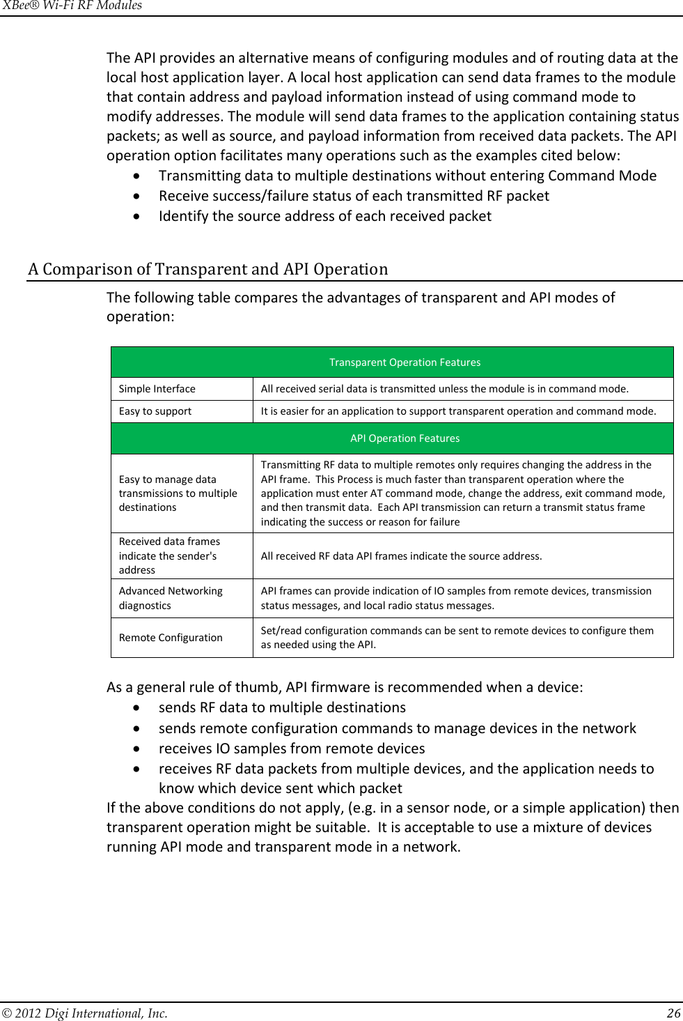
![XBee® Wi-Fi RF Modules © 2012 Digi International, Inc. 28 NOTE: Failure to enter AT Command Mode is most commonly due to baud rate mismatch. By default, the BD (Baud Rate) parameter = 3 (9600 bps). To Send AT Commands, send AT commands and parameters using the syntax shown below: To read a parameter value stored in the RF module’s register, omit the parameter field. The preceding example would change the RF module baud rate to 7, which would allow operation at 115,200bps. To store the new value to non-volatile (long term) memory, subsequently send the WR (Write) command. For modified parameter values to persist in the module’s registry after a reset, changes must be saved to non-volatile memory using the WR (Write) Command. Otherwise, parameters are restored to previously saved values after the module is reset. Command Response When a command is sent to the module, the module will parse and execute the command. Upon successful execution of a command, the module returns an “OK” message. If execution of a command results in an error, the module returns an “ERROR” message. Applying Command Changes Any changes made to the configuration command registers through AT commands will not take effect until the changes are applied. For example, sending the BD command to change the baud rate will not change the actual baud rate until changes are applied. Changes can be applied in one of the following ways: • The AC (Apply Changes) command is issued. • AT command mode is exited. To Exit AT Command Mode: 1. Send the ATCN (Exit Command Mode) command (followed by a carriage return). [OR] 2. If no valid AT Commands are received within the time specified by CT (Command Mode Timeout) Command, the RF module automatically returns to Idle Mode. For an example of programming the RF module using AT Commands and descriptions of each configurable parameter, please see the Command Reference Table chapter.](https://usermanual.wiki/Digi/S6BSM/User-Guide-1866580-Page-28.png)
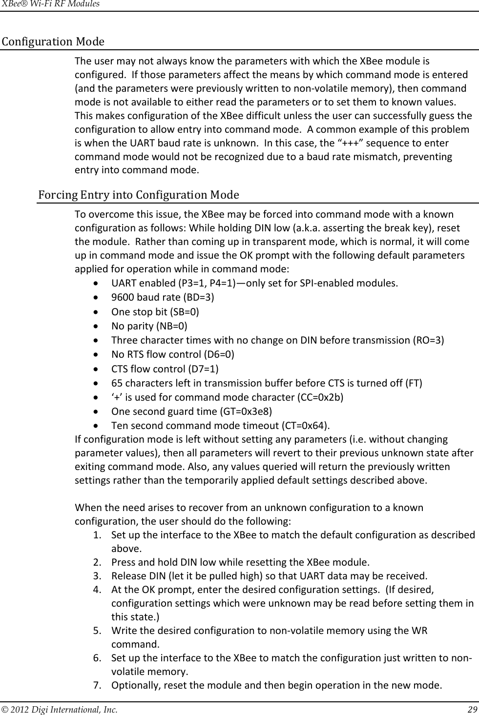

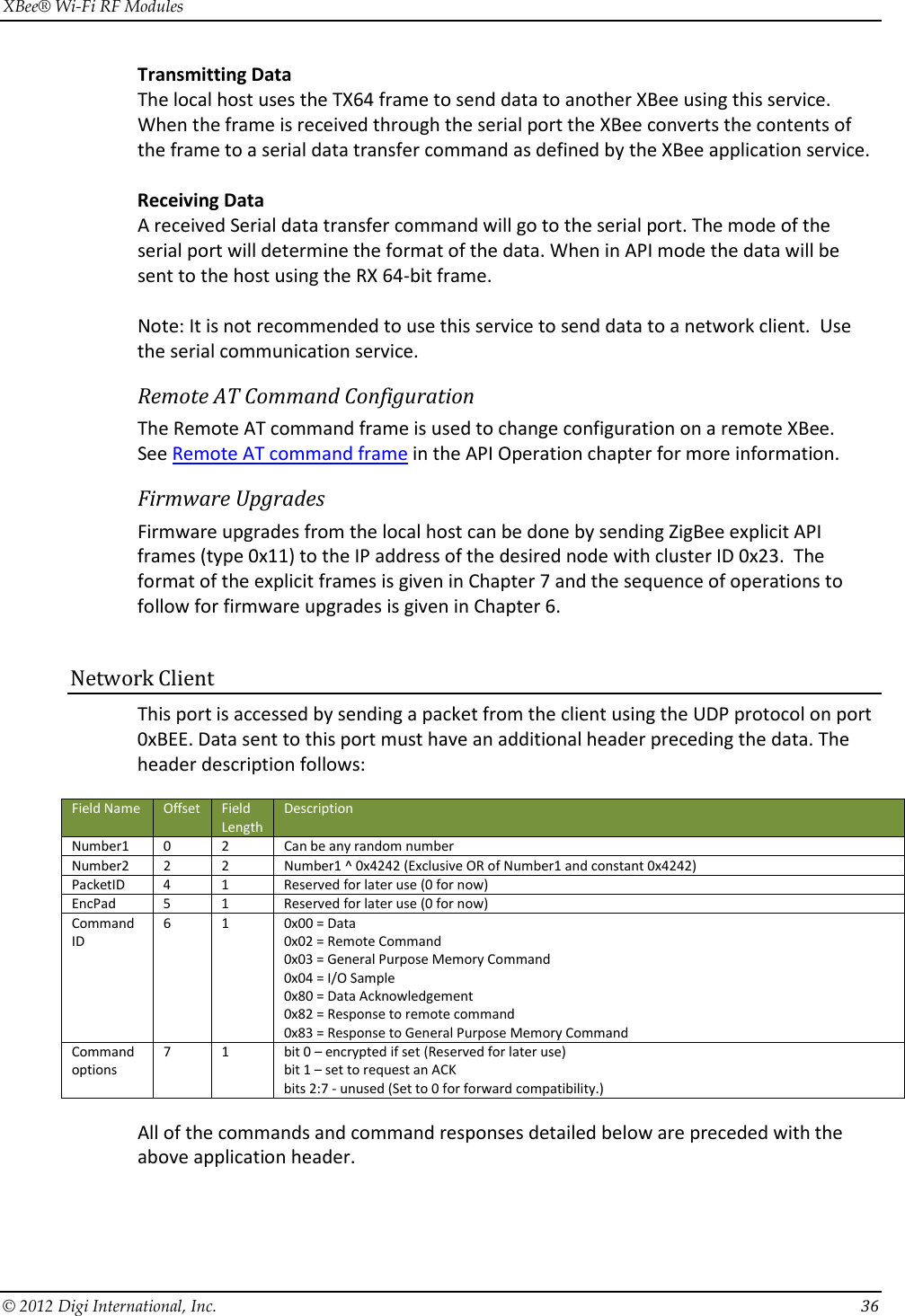
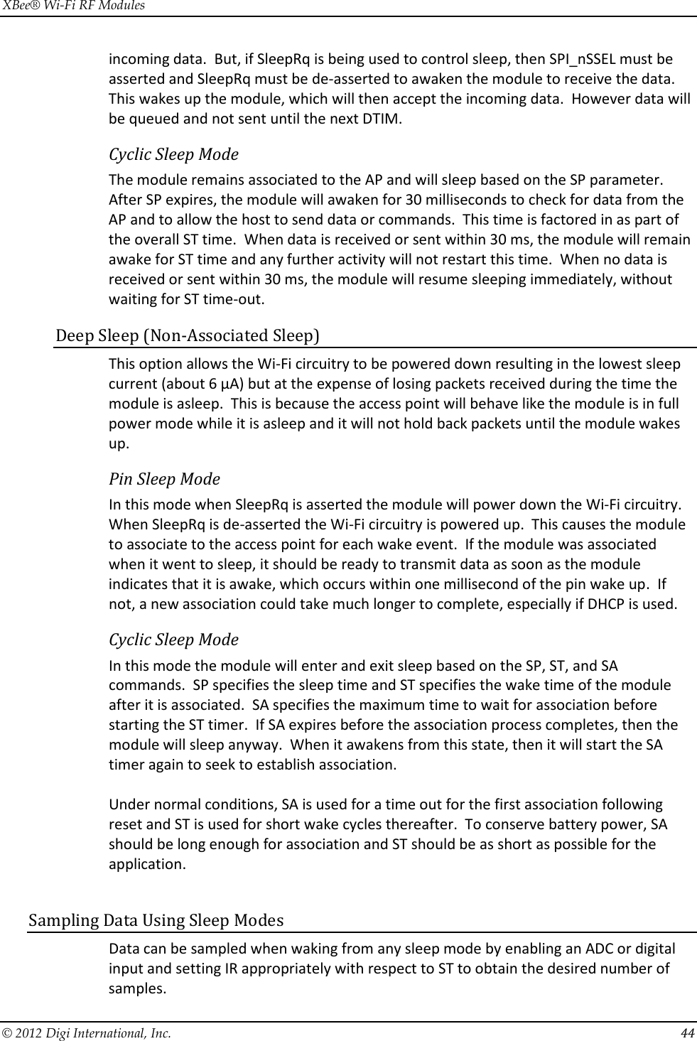
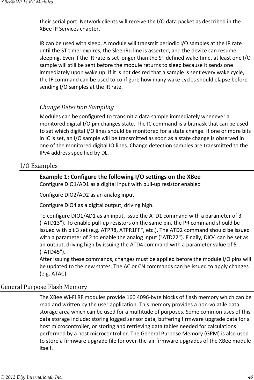
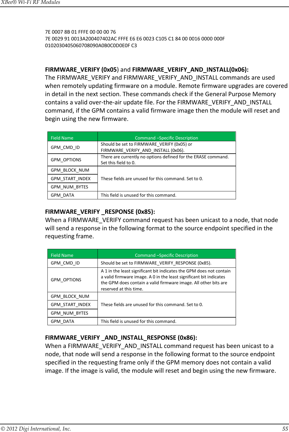
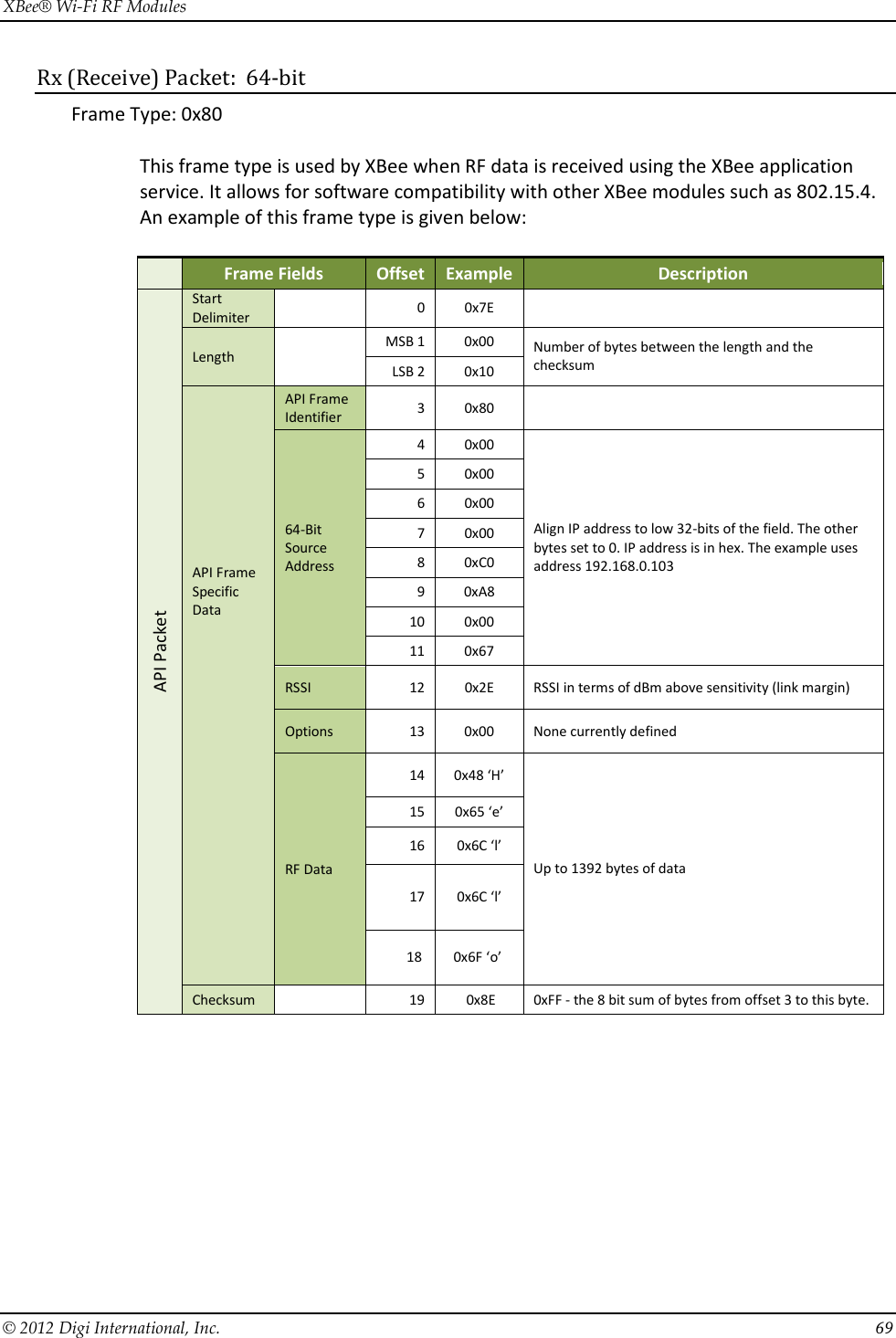
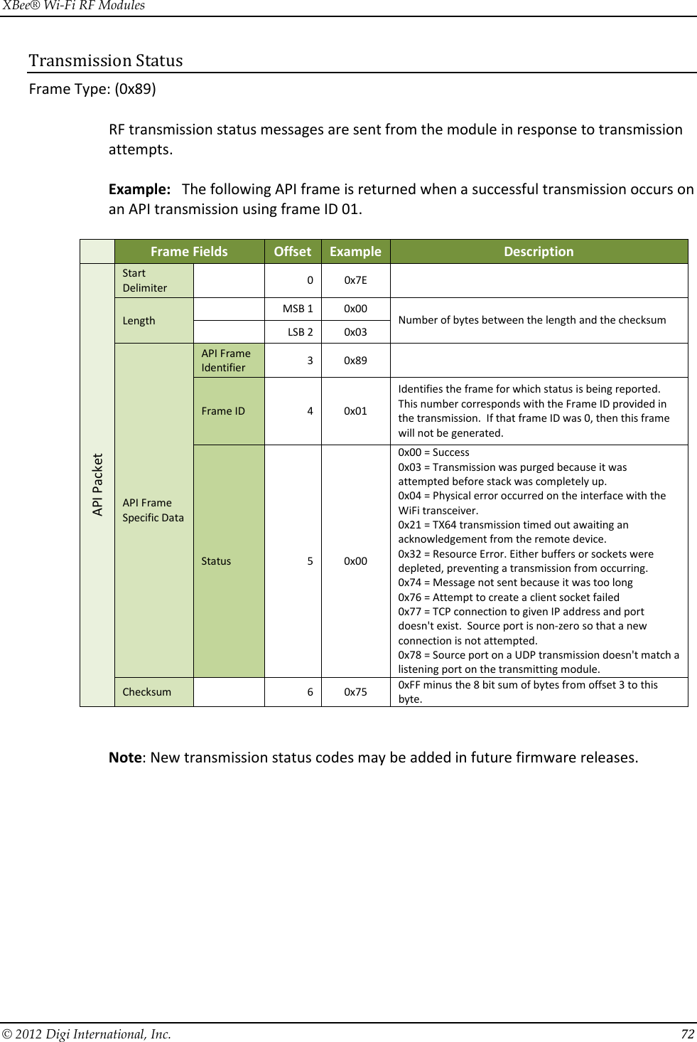
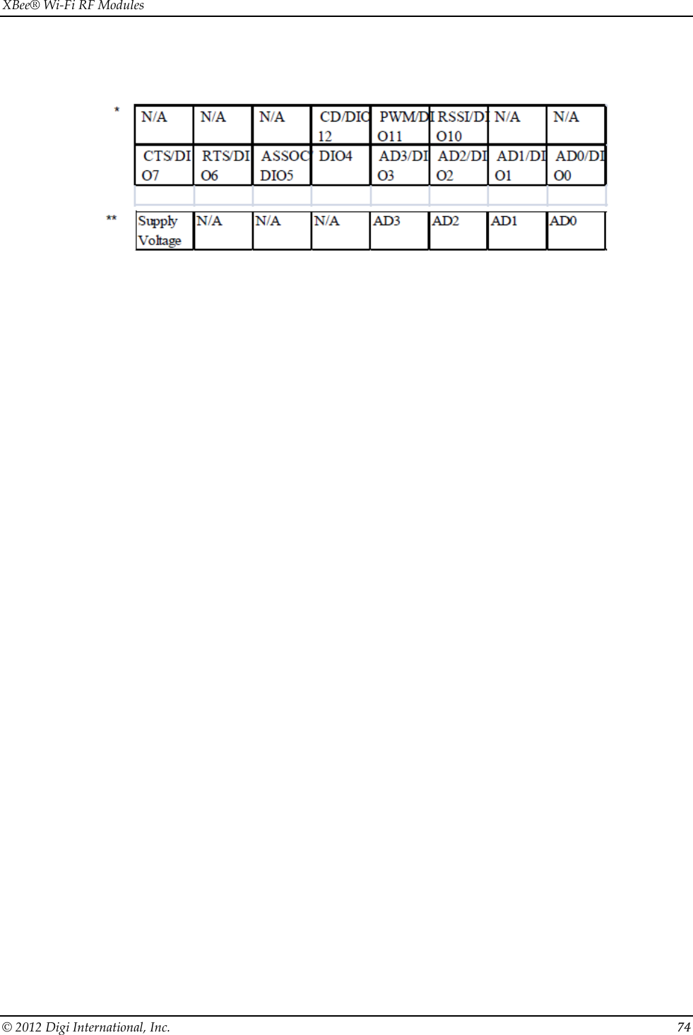
![XBee® Wi-Fi RF Modules © 2012 Digi International, Inc. 48 default. The analog inputs on the module are capped at 0x3FF. Analog samples are returned in order starting with AD0 and finishing with AD4. Only enabled analog input channels return data as shown in the example below. To convert the A/D reading to mV, do the following: AD (mV) = (A/D reading (converted to decimal) * VREF) / 1023 where VREF may be 1250 or 2500 Assuming that AV is set to the default value, the reading in the sample frame represents voltage inputs of 2385.14 mV (0x3D0) and 713.59 mV (0x124) for AD0 and AD1 respectively. Queried Sampling The IS command can be sent to a device locally, or to a remote device using the API remote command frame (see chapter 8 for details). When the IS command is sent and at least one I/O line is enabled as an input or an output, the receiving device samples all enabled digital I/O and analog input channels and returns an I/O sample. When no I/O line is enabled, IS will return nothing. If IS is sent locally, the I/O sample is sent out the UART or SPI port. If the IS command was received as a remote command, the I/O sample is sent over-the-air to the device that sent the IS command. If the IS command is issued in command mode, the module returns a carriage return-delimited list containing the above-listed fields. If the IS command is issued in API mode, the module returns an API command response packet with the I/O data included in the command data portion of the response frame. The following table shows an example of the fields in an IS response. Example Sample AT Response 0x01 [1 sample set] 0x0C0C [Digital Inputs: DIO 2, 3, 10, 11 selected] 0x03 [Analog Inputs; A/D 0,1] 0x0408 [Digital input states: DIO 3,10 high, DIO 2,11 low] 0x03D0 [Analog input ADIO 0=0x3D0] 0x0124 [Analog input ADIO 1=0x120] Periodic I/O Sampling Periodic sampling allows the XBee module to take an I/O sample and transmit it to a remote device at a periodic rate. The periodic sample rate is set by the IR command. If IR is set to 0 or there are no active I/O lines, periodic sampling is disabled. For all other values of IR, data will be sampled after IR milliseconds have elapsed and transmitted to a remote device. However, the module cannot keep up with transmitting an I/O sample more often than every three milliseconds. Therefore, when IR is set to 1 or 2, many samples are lost. The DL command determines the destination address of the I/O samples. DL can be set to transmit to a network client or another XBee Wi-Fi module. Only modules with API mode enabled for the serial port can send I/O data samples out](https://usermanual.wiki/Digi/S6BSM/User-Guide-1866580-Page-48.png)
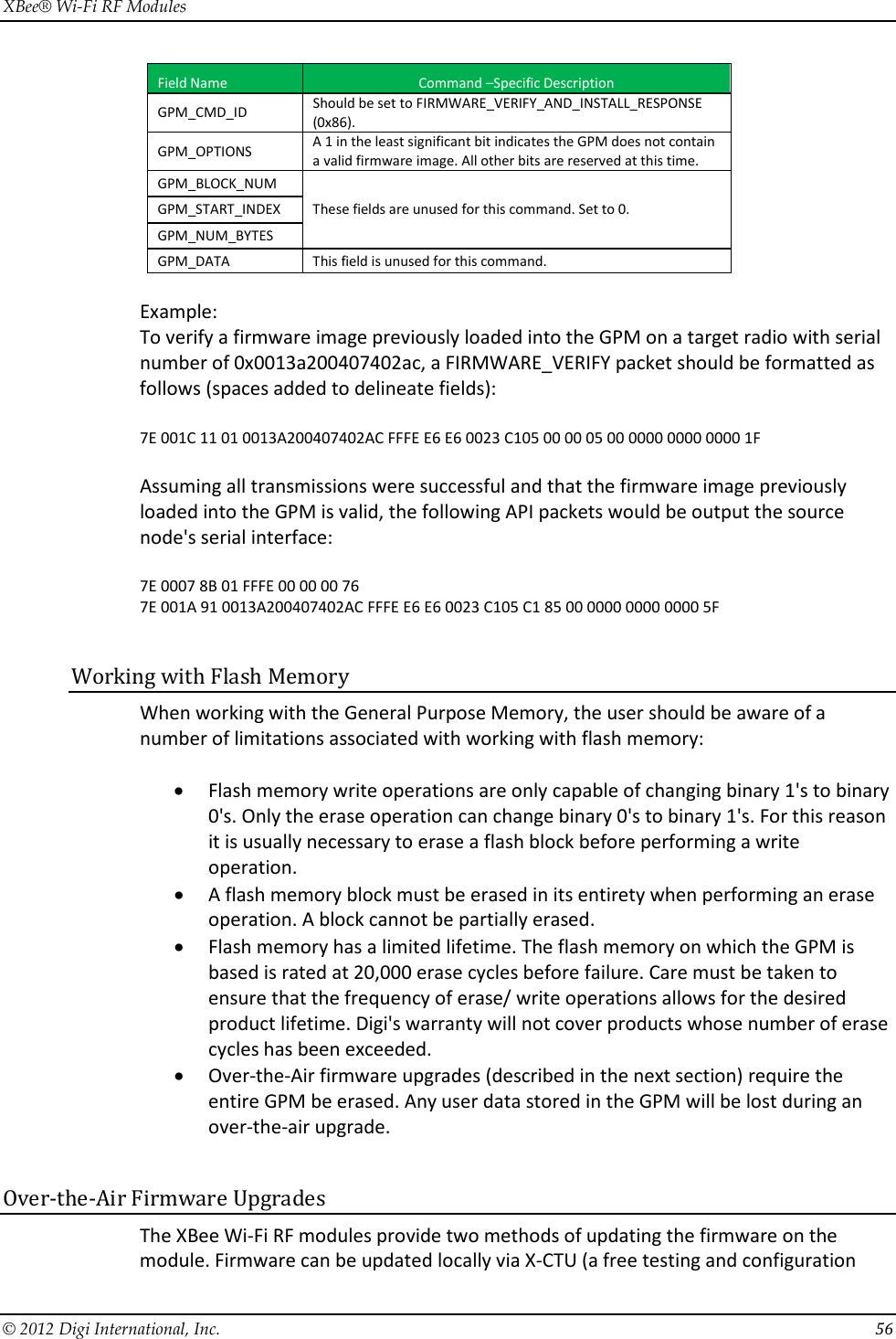
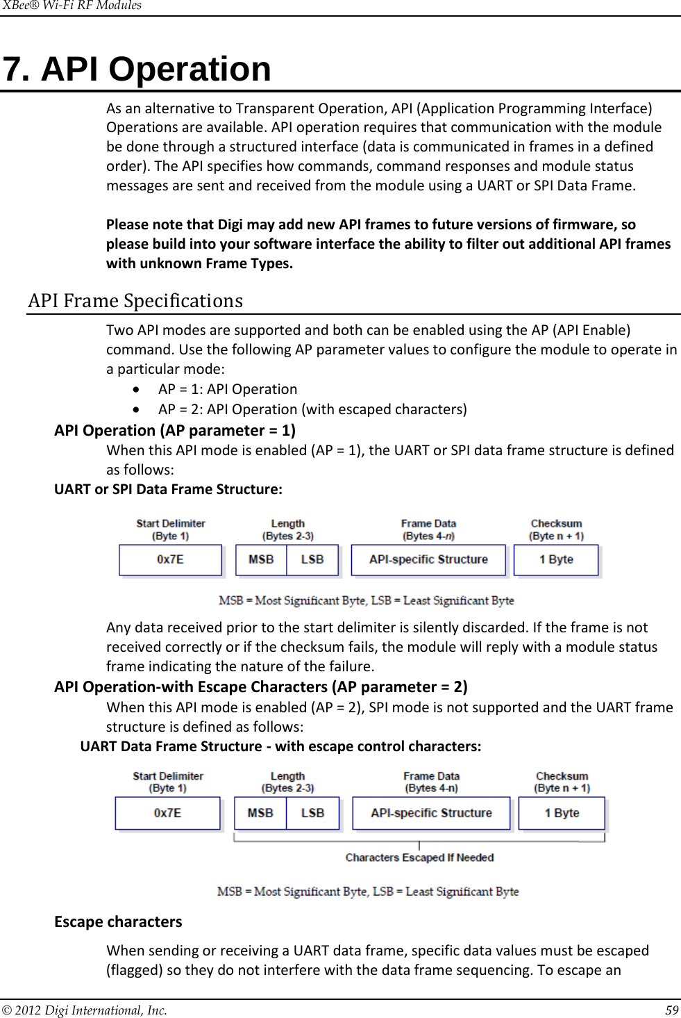
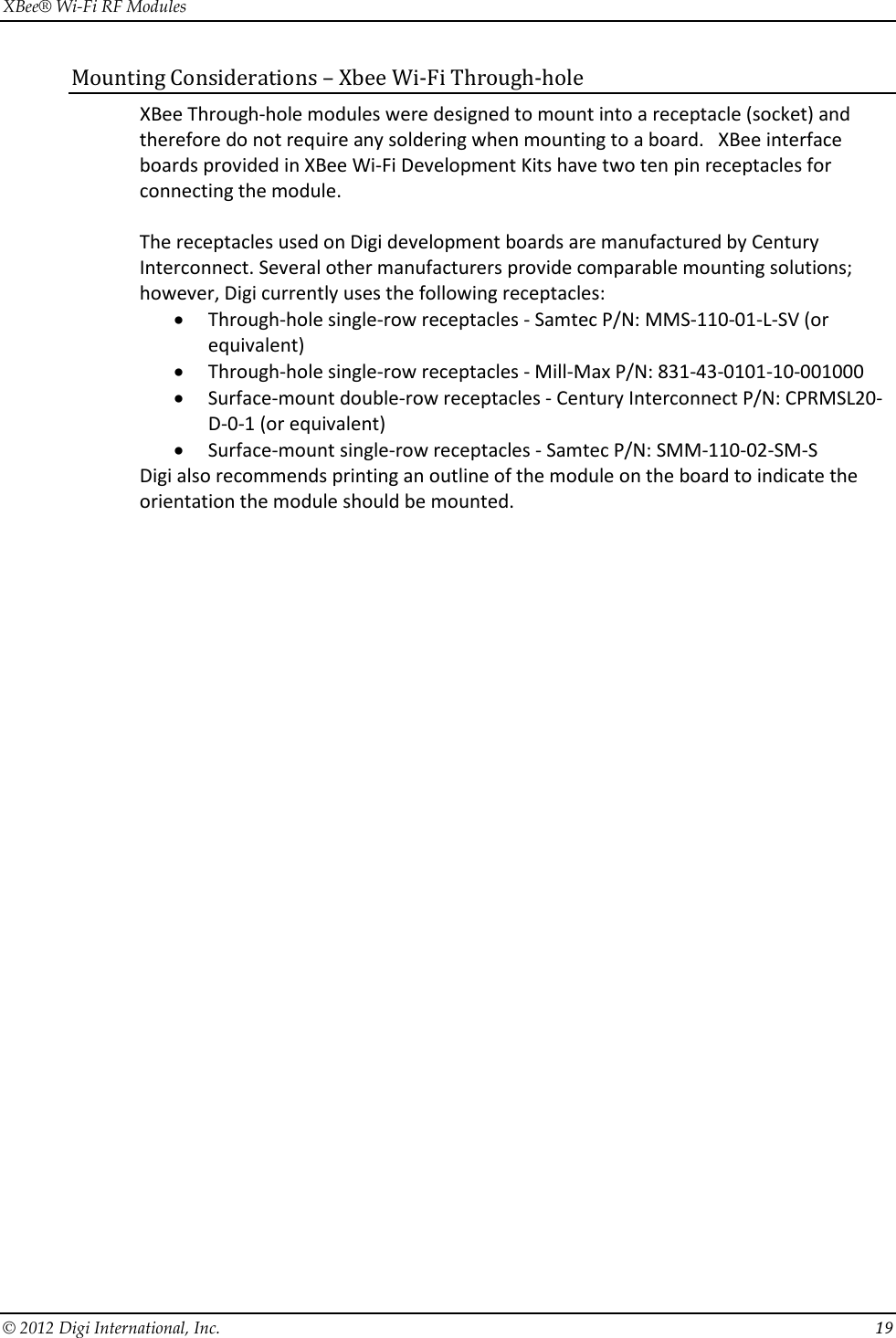
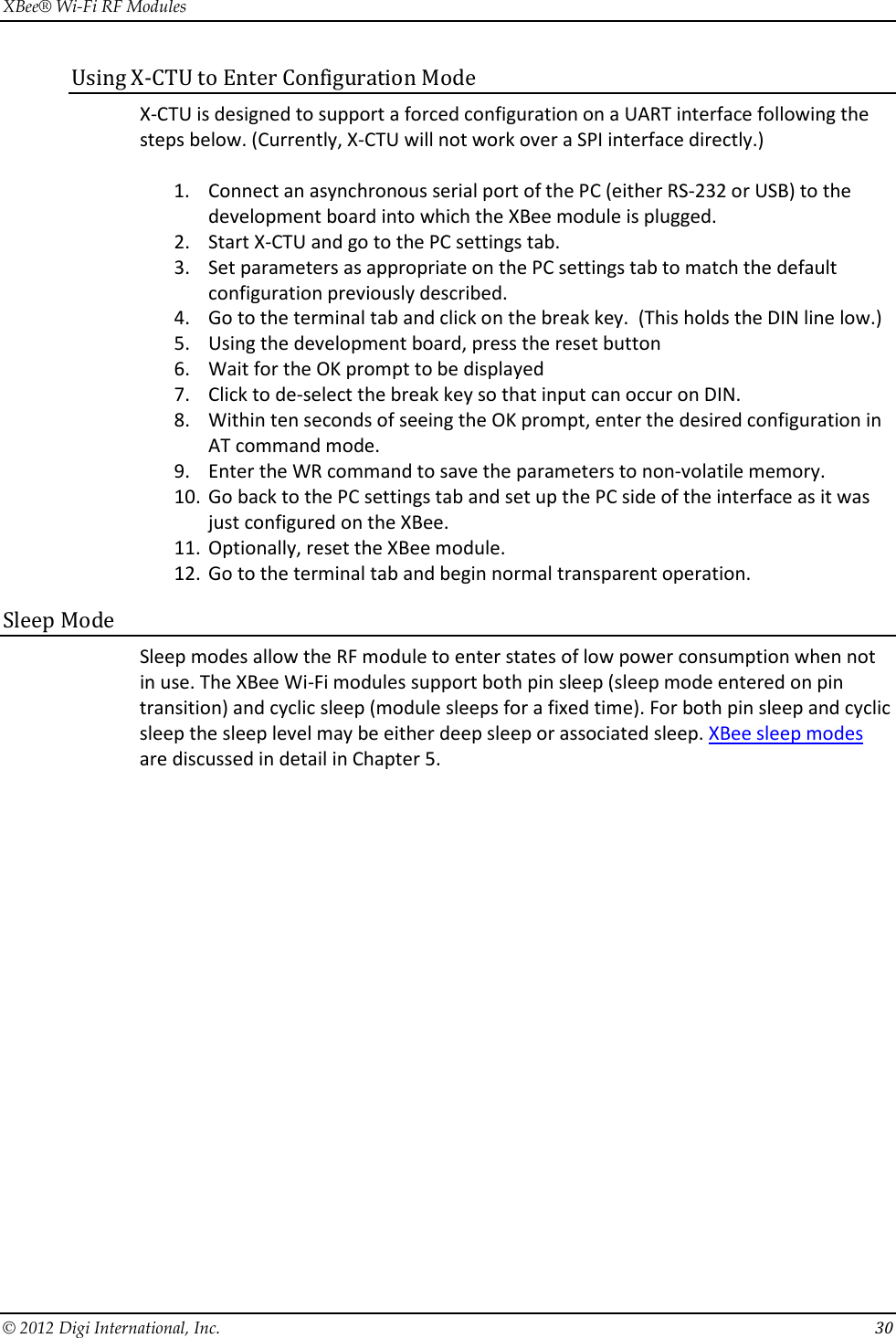
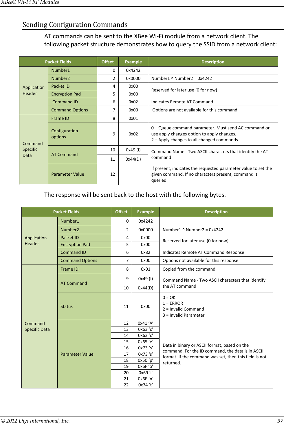
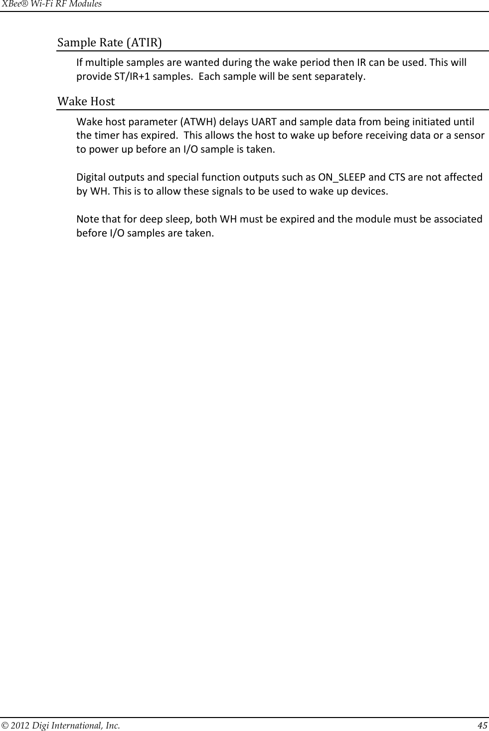
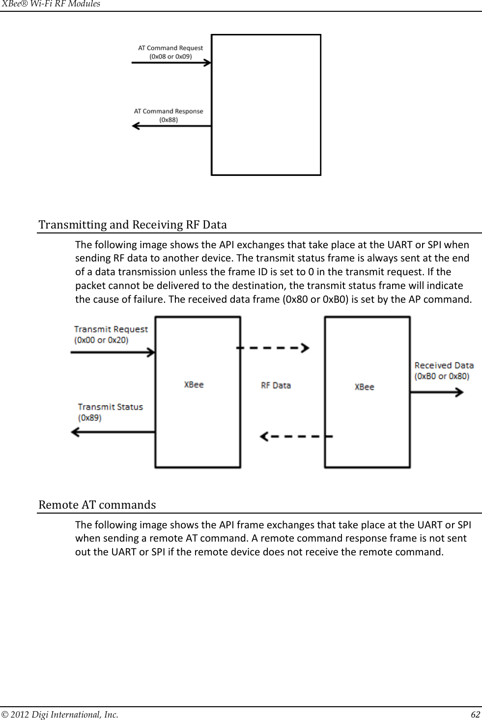
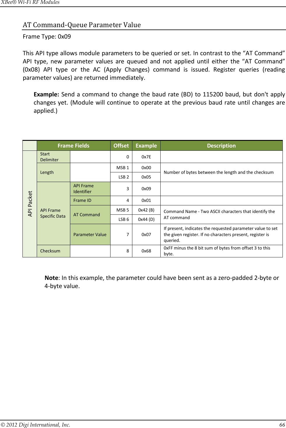
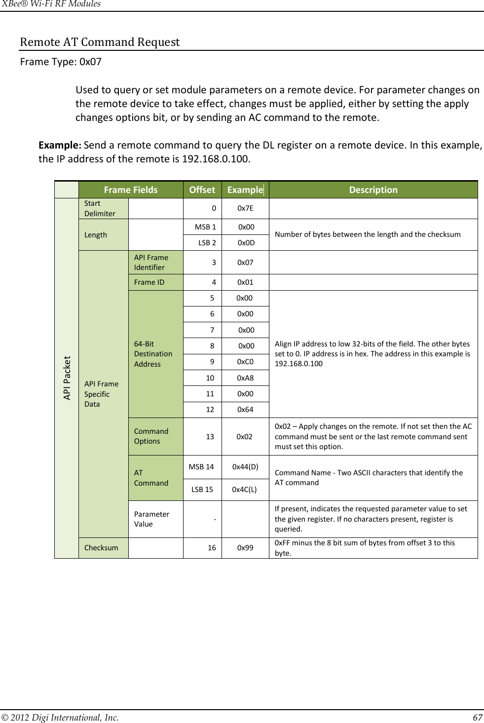
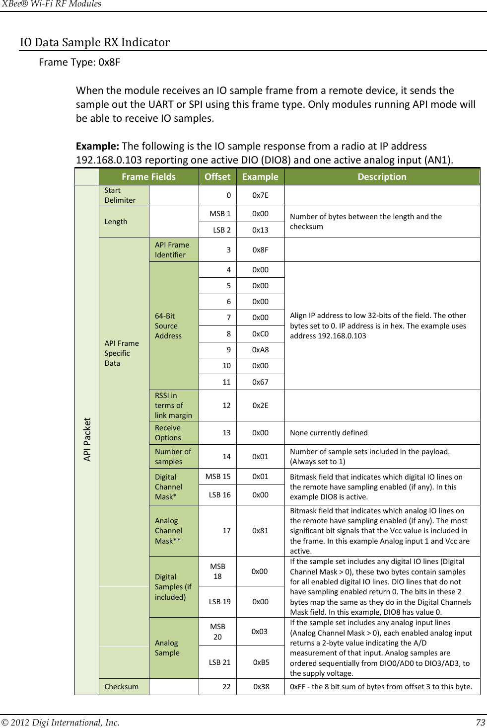
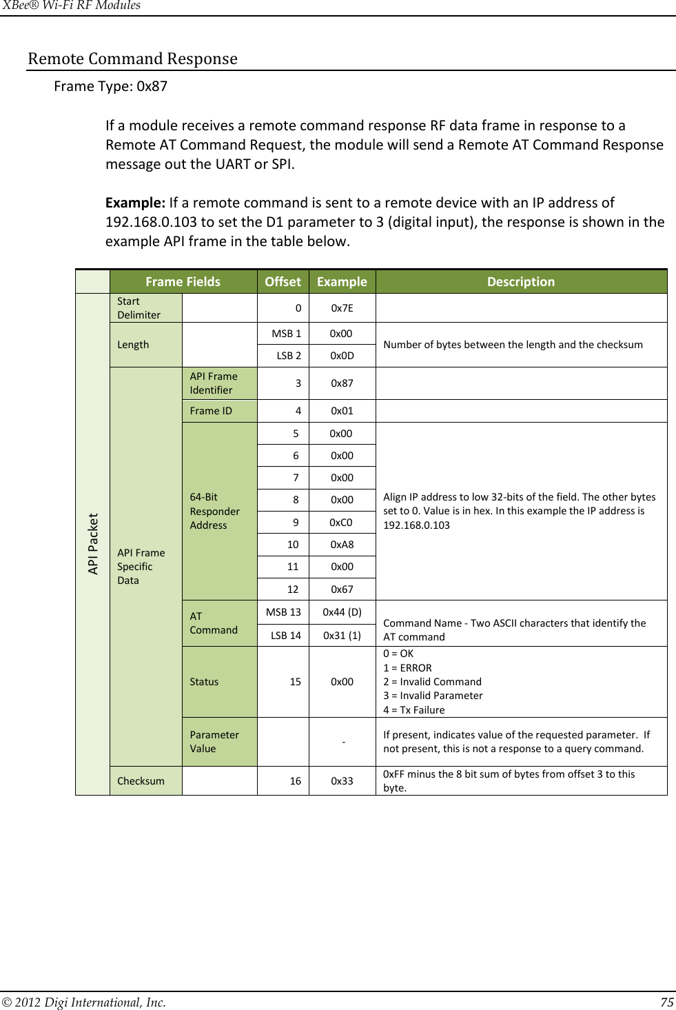
![XBee® Wi-Fi RF Modules © 2012 Digi International, Inc. 61 Checksum To test data integrity, a checksum is calculated and verified on non-escaped data. To calculate: Not including frame delimiters and length, add all bytes keeping only the lowest 8 bits of the result and subtract the result from 0xFF. To verify: Add all bytes (include checksum, but not the delimiter and length). If the checksum is correct, the sum will equal 0xFF. API Examples Example: Create an API AT command frame to configure an XBee baud rate to 230,400 (set BD to 0x08). The frame should look like (in hex): 7E 00 05 08 01 42 44 08 68 Where: 0x0005 = length excluding checksum 0x08 = AT Command API frame type 0x01 = Frame ID (set to non-zero value for transmit status) 0x4244 = AT Command ('BD') 0x08 = value to set command to 0x68 = Checksum The checksum is calculated as [0xFF - (0x08 + 0x01 + 0x42 + 0x44 + 0x08)] Example: Send a remote command to a module who’s IP address is 192.168.0.103 (C0 A8 00 67) to set DIO1/AD1 as a digital input (D1=3) and apply changes to force the IO update. The API remote command frame should look like (in hex): 7E 00 0E 07 01 00 00 00 00 C0 A8 01 64 02 44 31 03 B0 Where: 0x000E = length (14 bytes excluding checksum) 0x07 = Remote Command API frame type 0x01 = Frame ID 0x00000000 C0A80067 = Remote address (Pad first 4 bytes with 00) 0x02 = Apply Changes (Remote Command Options) 0x4431 = AT command ('D1') 0xB0 = Checksum API UART and SPI Exchanges AT Commands The following image shows the API frame exchange that takes place at the UART or SPI when sending an AT command request to read or set a module parameter. The response can be disabled by setting the frame ID to 0 in the request.](https://usermanual.wiki/Digi/S6BSM/User-Guide-1866580-Page-61.png)
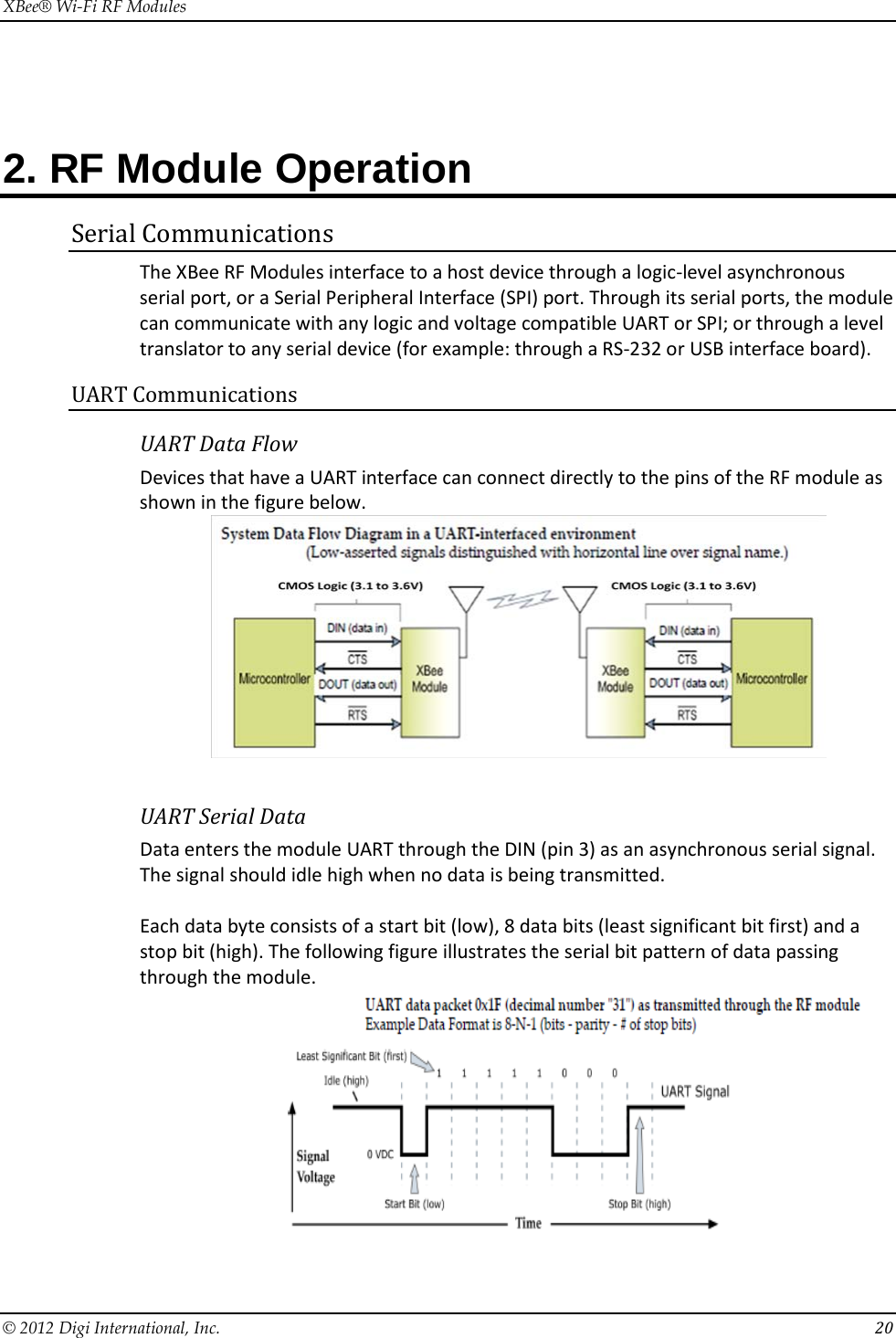
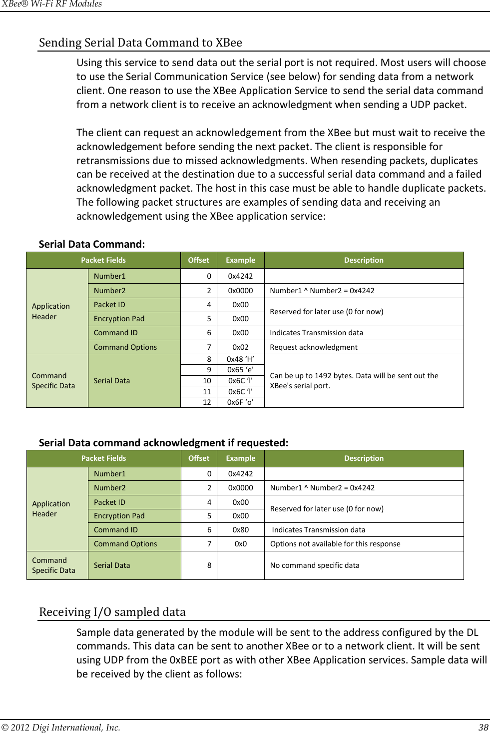
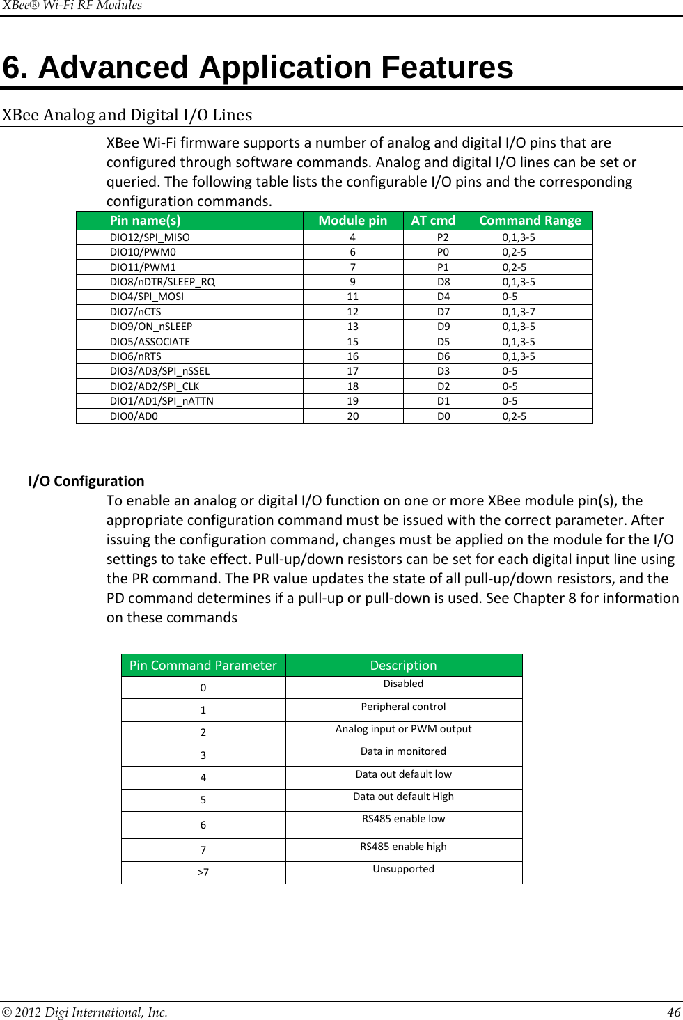
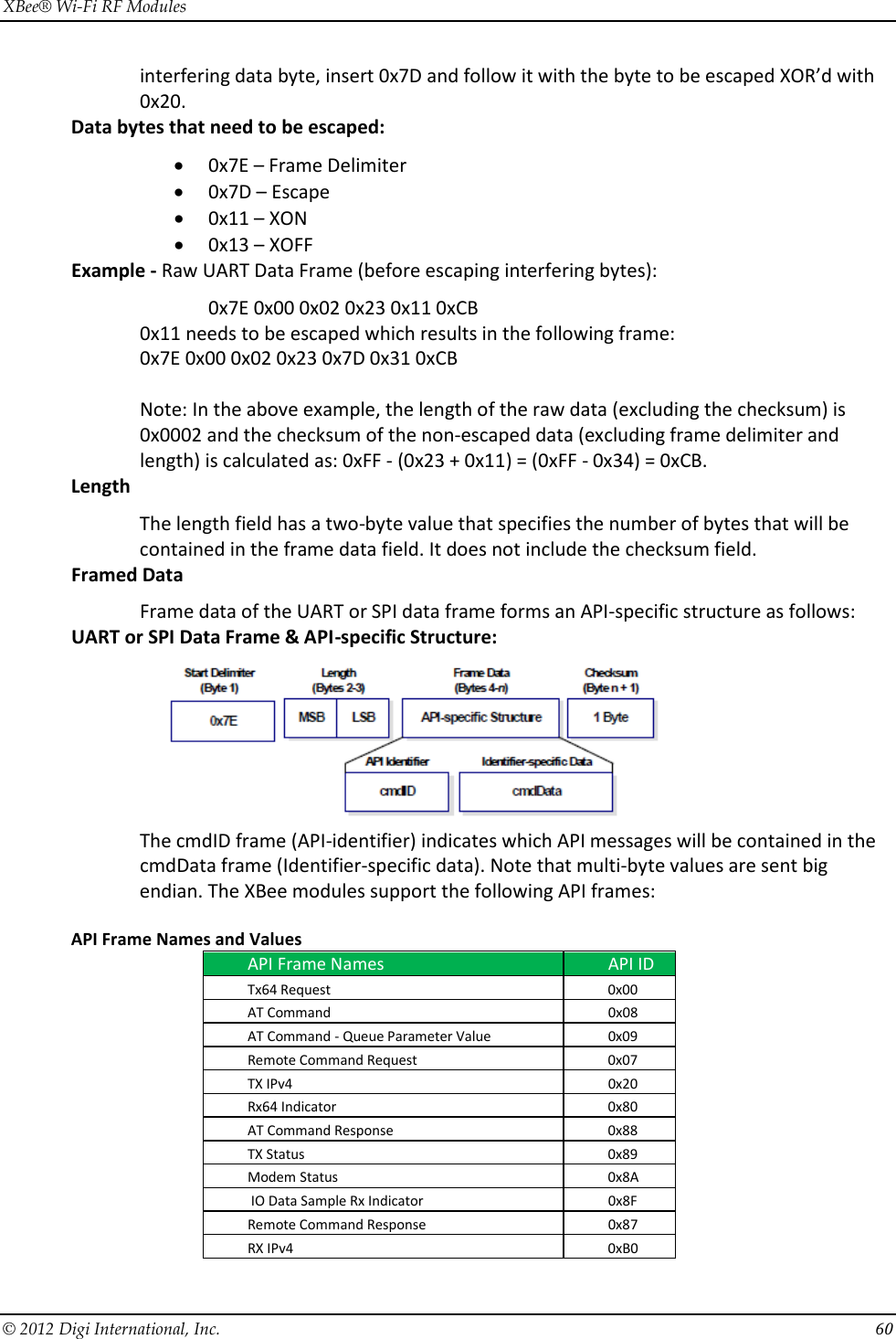
![XBee® Wi-Fi RF Modules © 2012 Digi International, Inc. 77 8. XBee Command Reference Tables Addressing AT Command Name and Description Parameter Range Default DL Destination Address Low. Set/Get the 32 bits of the IPv4 destination address. Using AT command mode this value is entered using dotted notation (example 192.168.0.100). 0.0.0.0 – 255.255.255.255 255.255.255.255 MY IP Network Address. Read the 32-bit network address of the module when using DHCP. Set/Read values when using static IP address. 0.0.0.0 – 255.255.255.255 0.0.0.0 MK IP Address Mask. This command is read only when DHCP is enabled. 0.0.0.0 – 255.255.255.255 0.0.0.0 GW Gateway IP address. This command is read only when DHCP is enabled. 0.0.0.0 – 255.255.255.255 0.0.0.0 SH Serial Number High. Read the high 16 bits of the module's unique 48-bit address. 0 - 0xFFFFFFFF [read-only] factory-set SL Serial Number Low. Read the low 32 bits of the module's unique 48-bit address. 0 - 0xFFFFFFFF [read-only] factory-set NI Node Identifier. Stores a string identifier. The register only accepts printable ASCII data. In AT Command Mode, a string cannot start with a space. A carriage return ends the command. Command will automatically end when maximum bytes for the string have been entered. 20-Byte printable ASCII string ASCII space character (0x20) DE Destination Port. Set/Get destination UDP/TCP port value. 0 - 0xFFFF 0x2616 C0 Serial Communication Service Port. Set/Get port number used to provide the serial communication service. Data sent to this port will come out of the serial port of the module. The protocol used is set by the IP command when UART is in transparent mode. 0 – 0xFFFF 0x2616 DD Device Type Identifier. Stores a device type value. This value can be used to differentiate different XBee-based devices. Digi reserves the range 0 - 0xFFFFFF. 0-0xFFFFFFFF 0x90000 NP Maximum RF Payload Bytes. This value returns the maximum number of RF payload bytes that can be sent in a transmission Note: NP returns a hexadecimal value. (e.g. if NP returns 0x54, this is equivalent to 84 bytes) 0 - 0xFFFF [read-only]](https://usermanual.wiki/Digi/S6BSM/User-Guide-1866580-Page-77.png)
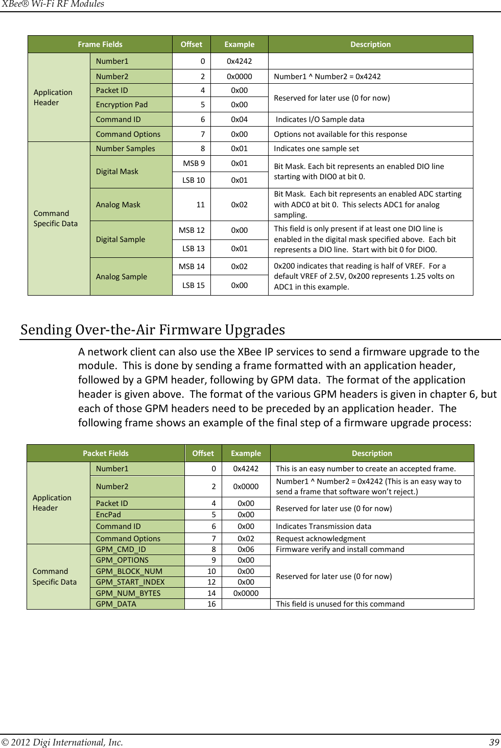
![XBee® Wi-Fi RF Modules © 2012 Digi International, Inc. 78 Networking Commands AT Command Name and Description Parameter Range Default ID SSID. Set/read the SSID of the access point, which may be up to 31 ASCII characters Up to 31 bytes of printable ASCII NULL AH Network Type. Set/read network type. Network types supported are Infrastructure (using an access point) and Adhoc (IBSS). 0-IBSS Joiner 1-IBSS Creator 2 - Infrastructure 2 IP IP Protocol. Set/Read the protocol used for the serial communication service. This is the port used by the C0 command. 0 – UDP 1 - TCP 0 MA IP Addressing Mode. Set / read the IP addressing mode. 0 – DHCP 1 – Static 0 TM TCP timeout. Set/Read the timeout for connection on TCP client sockets. If 0, socket closes immediately after data sent. 0-0xFFFF [x 100 msec] 0x64 TS TCP Server Socket Timeout. Set/Read the timeout for connection on a TCP server socket. This is a socket whose connection was initiated at the other end. 0 x000A– 0xFFFF * 100 ms. 0x0258 (1 minute) Security Commands AT Command Name and Description Parameter Range Default EE Encryption Enable. Set/Read the encryption enable setting. 0 – No security 1 – WPA 2 – WPA2 3 - WEP 0 PK Security Key. Set the security key used for WEP, WPA, and WPA2 security. This command is write only; PK cannot be read. 0 -31-ASCII characters for WPA and WPA2, Either 5 or 13 ASCII characters should be used for the WEP password, based on the access point key length (64 or 128 bits respectively). RF Interfacing Commands AT Command Name and Description Parameter Range Default PL Power Level. Select/Read the power level at which the RF module transmits conducted power. 0 – 0 dBm 1 – 5 dBm 2 – 10 dBm 3 – 15 dBm 4 – Max power 4 CH Channel. Read the channel number of the access point or 0xFF if not associated. Channel can be set when AH is configured for Adhoc creator mode. Note when using Adhoc mode, not all channels are available in all countries. It is the responsibility of the installer to use the appropriate channels. 1-0xB [read only]](https://usermanual.wiki/Digi/S6BSM/User-Guide-1866580-Page-78.png)
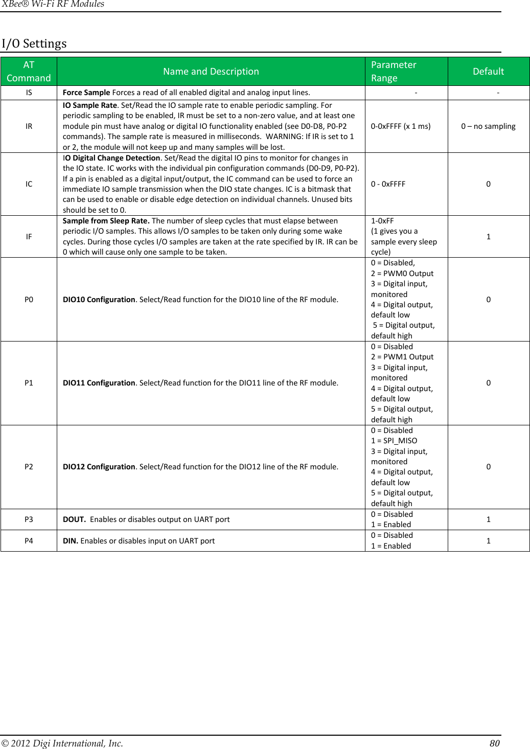
![XBee® Wi-Fi RF Modules © 2012 Digi International, Inc. 79 Serial Interfacing AT Command Name and Description Parameter Range Default AP API Enable. Enable API Mode. 0 = Transparent mode 1 = API-enabled 2 = API-enabled (w/escaped control characters) 1 AO API Output Options. Indicates the type of frame to output when data is received on the IP services port 0=ZigBee Rx 1=Explicit Zigbee Rx 2=RX64 2 (RX64) BD Interface Data Rate. Set/Read the serial interface data rate for communication between the module serial port and host. Any value above 0x0A will be interpreted as an actual baud rate. When a value above 0x0A is sent, the closest interface data rate represented by the number is stored in the BD register. 1 - 7 (standard baud rates) 1 = 2400 bps 2 = 4800 3 = 9600 4 = 19200 5 = 38400 6 = 57600 7 = 115200 8 = 230400 9 = 460,800 0xA = 921,600 0X5B9 - 0X5B8D80 (non-standard rates up to 6mps) 3 NB Serial Parity. Set/Read the serial parity setting on the module. 0 = No parity 1 = Even parity 2 = Odd parity 0 SB Stop Bits. Set/read the number of stop bits for the UART. (Two stop bits are not supported if mark parity is enabled.) 0 = 1 stop bit 1 = 2 stop bits 0 RO Packetization Timeout. Set/Read number of character times of inter-character silence required before packetization. Set (RO=0) to transmit characters as they arrive instead of buffering them into one RF packet . Regardless of how small RO is, the inter-character silence required to trigger a transmission of the data is 100 usec. 0 - 0xFF [x character times] 3 FT Flow Control Threshold. De-assert CTS when FT bytes are in the UART receive buffer 0x11 – 0x823 0x7F3 D7 DIO7 Configuration. Select/Read options for the DIO7 line of the RF module. 0 = Disabled 1 = CTS Flow Control 3 = Digital input 4 = Digital output, low 5 = Digital output, high 6 = RS-485 transmit enable (low enable) 7 = RS-485 transmit enable (high enable) 1 D6 DIO6 Configuration. Configure options for the DIO6 line of the RF module. 0 = Disabled 1 = RTS flow control 3 = Digital input 4 = Digital output, low 5 = Digital output, high 0](https://usermanual.wiki/Digi/S6BSM/User-Guide-1866580-Page-79.png)
![XBee® Wi-Fi RF Modules © 2012 Digi International, Inc. 83 Diagnostics Interfacing AT Command Name and Description Parameter Range Default VR Firmware Version. Read firmware version of the module. The firmware version returns 4 hexadecimal values (2 bytes) "ABCD". Digits ABC are the main release number and D is the revision number from the main release. "B" is a variant designator where 0 means standard release. 0 - 0xFFFF [read-only] Factory-set HV Hardware Version. Read the hardware version of the module. This command can be used to distinguish among different hardware platforms. The upper byte returns a value that is unique to each module type. The lower byte indicates the hardware revision. XBee WiFi modules return 0x1Fxx for the HV command. 0 - 0xFFFF [read-only] Factory-set HS Hardware Series. Indicates the hardware series number of the module. This module should indicate 0x601 for S6B. AI Association Indication. Read information regarding last node join request: 0x00 - Successfully joined an access point, established IP addresses and IP listening sockets. 0x01 - WiFi transceiver initialization in progress. 0x02 - WiFi transceiver initialized, but not yet scanning for access point. 0x13 - Disconnecting from access point. 0x23 – SSID not configured. 0x24 - Encryption key invalid (either NULL or invalid length for WEP) 0x27 – SSID was found, but join failed. 0x41 – Module joined a network and is waiting for IP configuration to complete, which usually means it is waiting for a DHCP provided address. 0x42 – Module is joined, IP is configured, and listening sockets are being set up. 0xFF– Module is currently scanning for the configured SSID. Note: New non-zero AI values may be added in later firmware versions. Applications should read AI until it returns 0x00, indicating a successful startup. 0 - 0xFF [read-only] - AS Active Scan. Scan for access points in the vicinity. This command can only be issued when SSID is NULL, which can be forced by first issuing the NR command. If SSID is not NULL, then the active scan command returns an error. This command may be issued in command mode or in API mode. In either case, the following information is returned for each access point found: 02 – Indicates scan type of 802.11 in this format unique to S6B. CH - Channel number in use by access point ST – Security type where: 00=open, 01=WPA, 02=WPA2, and 03=WEP LM - Link Margin (Signal strength in dBm above sensitivity) ID = SSID of access point found. When this command is issued in command mode, the above record is displayed, one per line for each access point found. Readable ASCII characters are outputs with a carriage return and each field on a new line. When it is issued in API mode, each record (i.e. each access point) outputs a separate AT command response of type 0x88 with the above fields in binary format. Note that this command is not available as a remote command. - - TP Temperature. Read temperature of module in degrees Celsius. -40 to 85C - CK Configuration Code. Read the configuration code associated with the current AT command configuration 2 bytes - %V Supply Voltage. Read supply voltage in millivolt units. 3.1 to 3.6V - LM Link Margin. Reads the received signal strength (RSSI) in terms of dBm units above sensitivity. It will report 0xff until the first reception after connection to access point. 0 – 0xFF](https://usermanual.wiki/Digi/S6BSM/User-Guide-1866580-Page-83.png)
![XBee® Wi-Fi RF Modules © 2012 Digi International, Inc. 84 AT Command Options AT Command Name and Description Parameter Range Default CT Command Mode Timeout. Set/Read the period of inactivity (no valid commands received) after which the RF module automatically exits AT Command Mode and returns to Idle Mode. This time can be up to ten minutes. 2 - 0x1770 [x 100 ms] 0x64 (100d) CN Exit Command Mode. Explicitly exit the module from AT Command Mode. (Whether command mode is left by the CN command or by CT timing out, changes will be applied upon exit. - - GT Guard Times. Set required period of silence before and after the Command Sequence Characters of the AT Command Mode Sequence (GT + CC + GT). The period of silence is used to prevent inadvertent entrance into AT Command Mode. 2 - 0x0CE4 [x 1 ms] (max of 3.3 decimal sec) 0x3E8 (1000d) CC Command Mode Character Set/read the command mode character used between guard times of the AT Command Mode Sequence (GT + CC + CC + CC + GT). This sequence allows the module to enter into AT Command Mode. 0 - 0xFF 0x2B (‘+’ ASCII) Sleep Commands AT Command Name and Description Parameter Range Default SM Sleep Mode Sets the sleep mode on the RF module. Sleep mode is also affected by the SO command, option bit 6. See the “Sleep” chapter for a full explanation of the various sleep modes. 0 = No sleep 1 = Pin sleep 4 = Cyclic sleep 5 = Cyclic sleep, pin wake 0 SP Sleep Period. This value determines how long the device will sleep at a time, up to 24 hours or 86,400 seconds. This corresponds to 0x83d600 in 10ms units. 1 - 0x83D600 x 10ms 0xC8 (2 seconds) SO Command Sleep Options. Configure options for sleep. Unused option bits should be set to 0. Sleep options include: 0x40 – Stay associated with AP during sleep. Draw more current during sleep with this option enabled, but also awake from sleep more rapidly. 0x100 – For cyclic sleep, ST specifies the time before returning to sleep. With this bit set, new receptions from either the serial or the RF port will NOT restart the ST timer. Current implementation does not support this bit being turned off. 0 - 0x01FF 0x100 WH Wake Host. Set/Read the wake host timer value. If the wake host timer is set to a non-zero value, this timer specifies a time (in millisecond units) that the device should allow after waking from sleep before sending data out the UART or transmitting an IO sample. If serial characters are received, the WH timer is stopped immediately. 0 - 0xFFFF (x 1ms) 0 ST Wake Time. Wake time for cyclic modes. New data will not refresh the timer. However, if there is data to transmit or receive after ST expires, those actions will occur before the module goes to sleep. Max wake time is 3600 seconds. 0x1 – 0x36EE80 (x 1 ms) 0x7D0 SA Association Timeout. Time to wait for association before entering deep sleep. (Wakeup from deep sleep is much faster if association occurs before going to sleep.) 0x1 – 0x36EE80 (x1 ms) 0x2710 (10 seconds)](https://usermanual.wiki/Digi/S6BSM/User-Guide-1866580-Page-84.png)
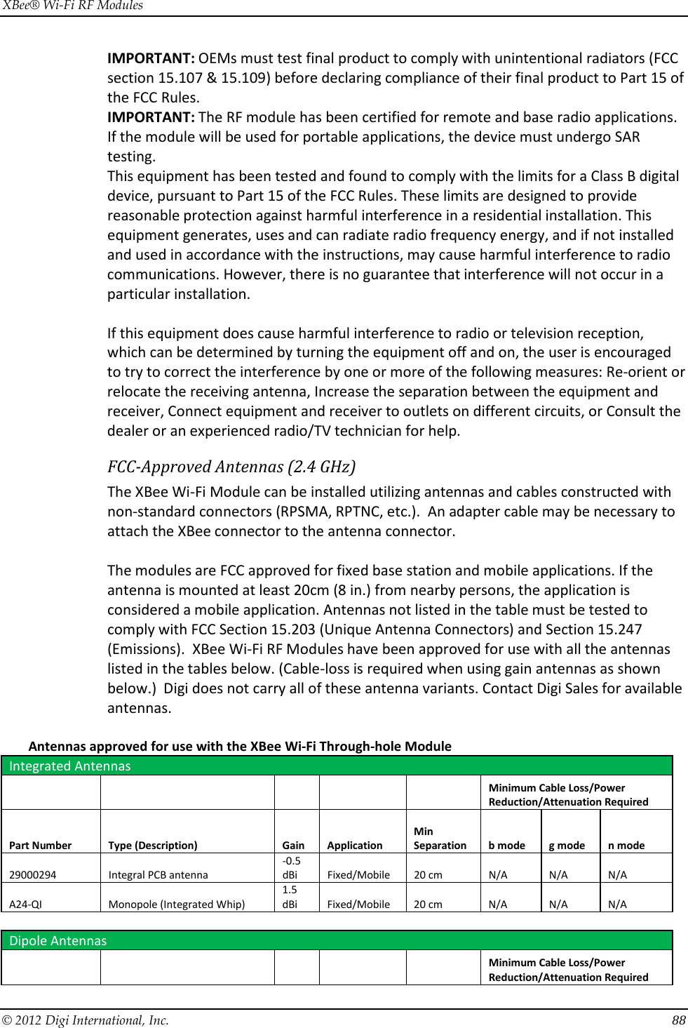
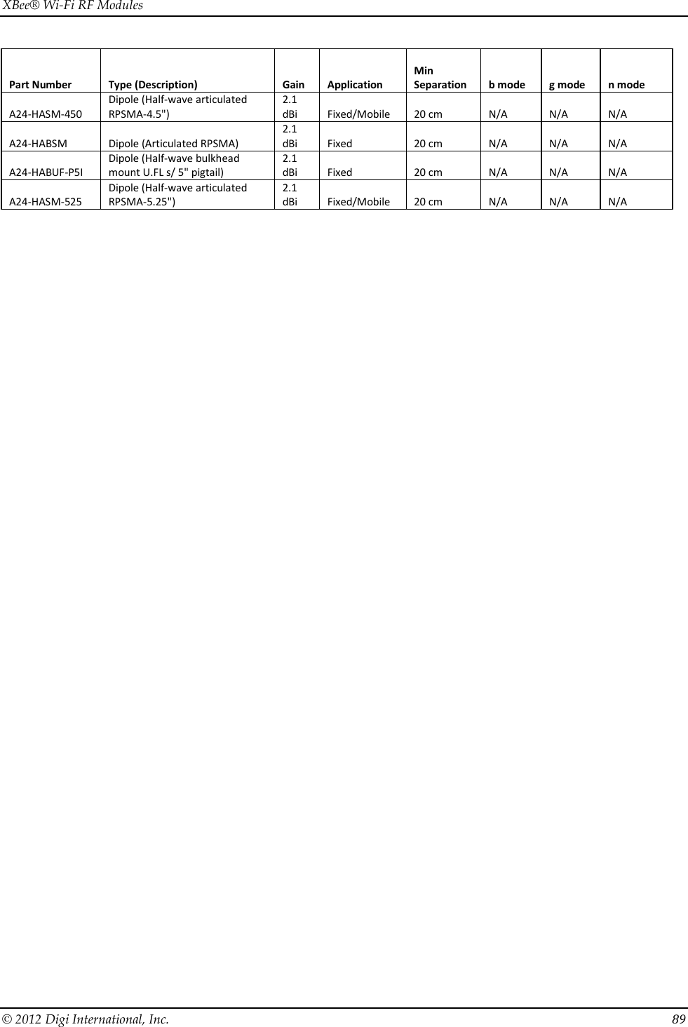
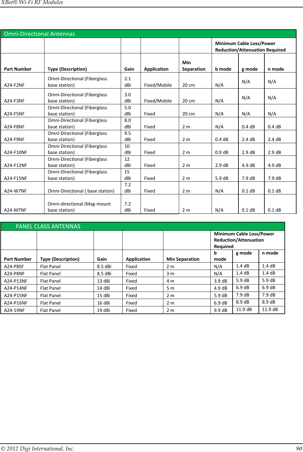
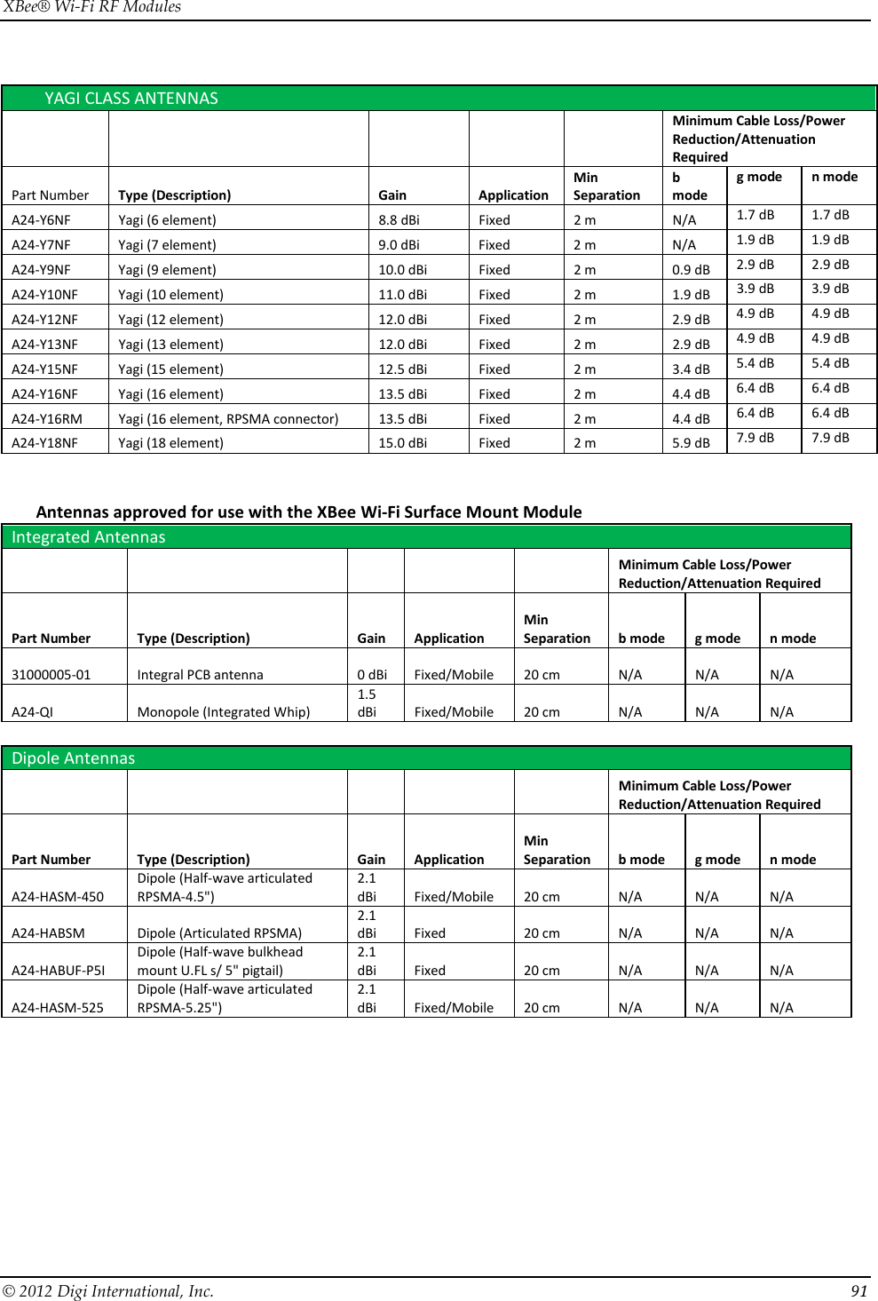
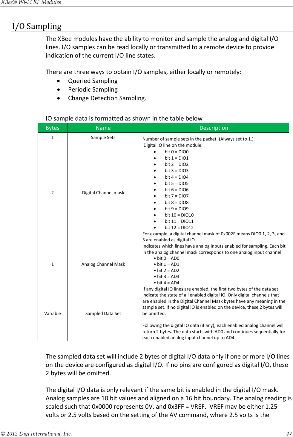
![XBee® Wi-Fi RF Modules © 2012 Digi International, Inc. 87 10. Agency Certifications United States FCC This device complies with Part 15 of the FCC Rules. Operation is subject to the following two conditions: (1) this device may not cause harmful interference and (2) this device must accept any interference received, including interference that may cause undesired operation. The XBee Wi-Fi Module complies with Part 15 of the FCC rules and regulations. Compliance with the labeling requirements, FCC notices and antenna usage guidelines is required. To fulfill FCC Certification, the OEM must comply with the following regulations: 1. The system integrator must ensure that the text on the module label is placed on the outside of the final product. 2. XBee Wi-Fi Module may only be used with antennas that have been tested and approved for use with this module [refer to the antenna tables in this section]. OEM Labeling Requirements WARNING: The Original Equipment Manufacturer (OEM) must ensure that FCC labeling requirements are met. This includes a clearly visible label on the outside of the final product enclosure. Required FCC Label for OEM products containing the XBee Wi-Fi S6B Through-hole Module Contains FCC ID: MCQ-XBS6B The enclosed device complies with Part 15 of the FCC Rules. Operation is subject to the following two conditions: (i.) this device may not cause harmful interference and (ii.) this device must accept any interference received, including interference that may cause undesired operation. Required FCC Label for OEM products containing the XBee Wi-Fi S6B Surface Mount Module Contains FCC ID: MCQ-S6BSM The enclosed device complies with Part 15 of the FCC Rules. Operation is subject to the following two conditions: (i.) this device may not cause harmful interference and (ii.) this device must accept any interference received, including interference that may cause undesired operation. The integrator is responsible for its product to comply with FCC Part 15, Sub. B - Unintentional Radiators. FCC Notices IMPORTANT: The XBee Module has been certified by the FCC for use with other products without any further certification (as per FCC section 2.1091). Modifications not expressly approved by Digi could void the user's authority to operate the equipment.](https://usermanual.wiki/Digi/S6BSM/User-Guide-1866580-Page-87.png)