Digi WDNU Wireless tracker installed in plane User Manual WDNU Users Manual Outline
Digi International Inc Wireless tracker installed in plane WDNU Users Manual Outline
UserManual.wiki
>
Digi
>
WDNU User Manual
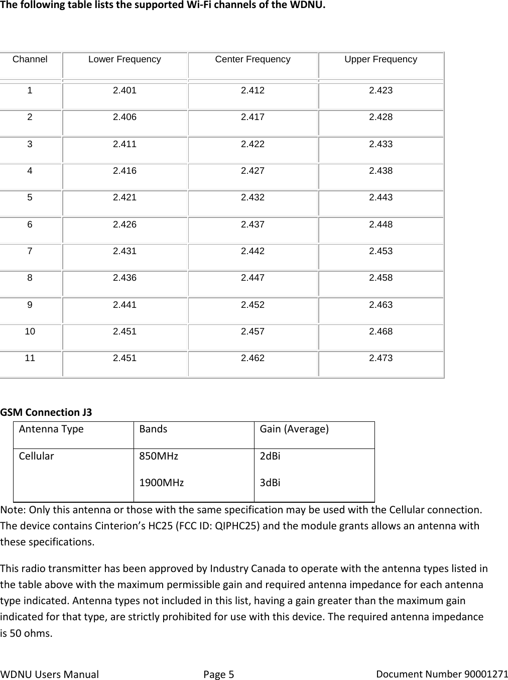
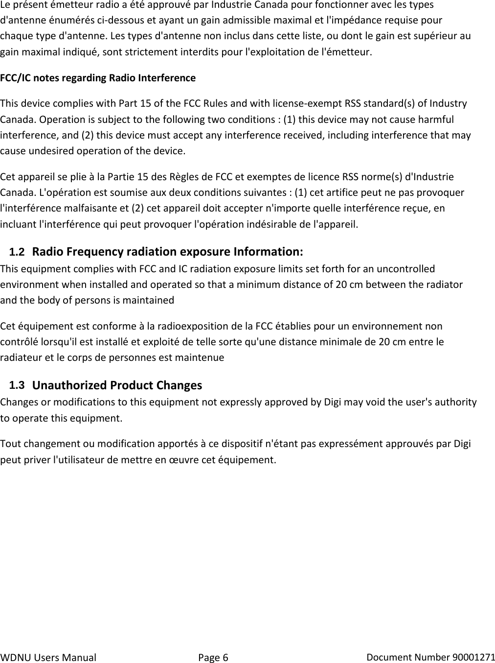
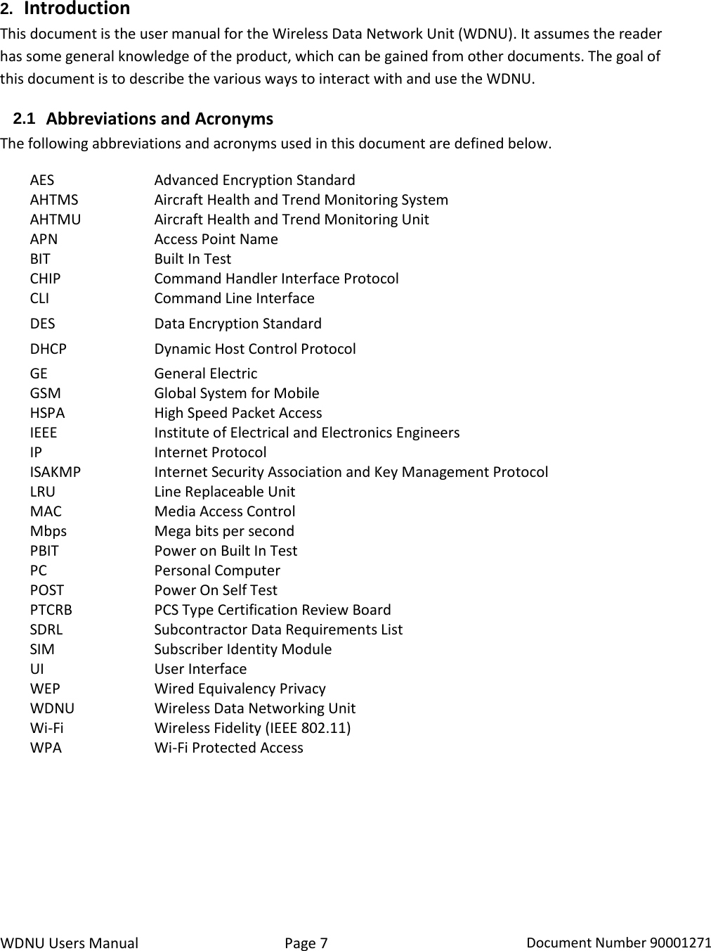
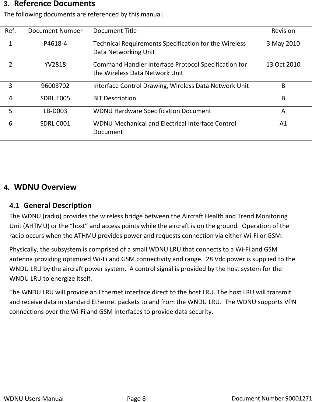
User/Installation Manual
Navigation menu
Upload a User Manual
Namespaces
Wiki Guide
HTML
PDF
Info
Views
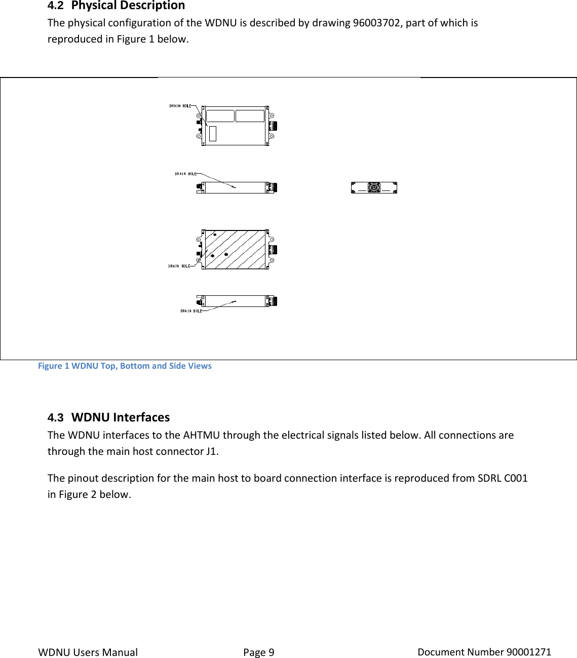
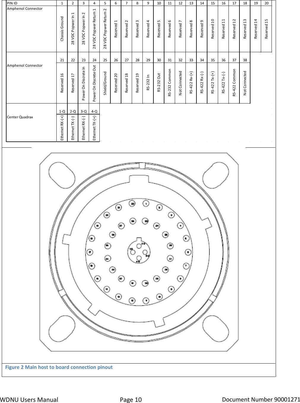
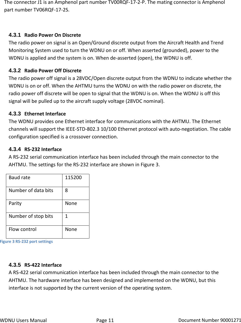
User Manual
Discussion / Help
Navigation