Digi WDNU Wireless tracker installed in plane User Manual WDNU Users Manual Outline
Digi International Inc Wireless tracker installed in plane WDNU Users Manual Outline
Digi >
User/Installation Manual
Users Manual
Wireless Data Networking Unit
Prepared By:
Spectrum Design Solutions
Subsidiary of Digi International
11001 Bren Road E
Minnetonka, MN 55343
SDRL C005
Document Revision: H
Document Number 90001271

WDNU Users Manual
Page 2
Document Number 90001271
Revision History
REV
DESCRIPTION
DATE
1
Original
3/7/2011
2
A
B
C
D
E
Updates from peer review, LOT 03302011
Release
Add Digi Document Number
Added FCC notes
Fixed Typos
Added Regulatory Information and Cert section
4/8/2011
6/29/2011
9/20/2011
6/4/2012
6/18/2012
6/20/2012
F
G
H
Updated Regulatory Information
Added supported Wi-Fi channels
Revised Regulatory Information and Cert section
7/3/2012
7/24/2012
7/25/2012
Table of Contents
1. Regulatory Information and Certifications .............................................................................. 4
1.1 Antenna Related User Notification .................................................................................. 4
WiFi Connection J2 .................................................................................................................. 4
List of Supported WiFi Channels .......................................................................................................... 5
GSM Connection J3 .................................................................................................................. 5
1.2 Radio Frequency radiation exposure Information: .......................................................... 6
1.3 Unauthorized Product Changes ....................................................................................... 6
2. Introduction ............................................................................................................................. 7
2.1 Abbreviations and Acronyms ........................................................................................... 7
WDNU Users Manual
Page 3
Document Number 90001271
3. Reference Documents ............................................................................................................. 8
4. WDNU Overview ...................................................................................................................... 8
4.1 General Description.......................................................................................................... 8
4.2 Physical Description ......................................................................................................... 9
4.3 WDNU Interfaces .............................................................................................................. 9
4.3.1 Radio Power On Discrete ........................................................................................ 11
4.3.2 Radio Power Off Discrete ........................................................................................ 11
4.3.3 Ethernet Interface ................................................................................................... 11
4.3.4 RS-232 Interface ...................................................................................................... 11
4.3.5 RS-422 Interface ...................................................................................................... 11
4.4 WDNU RF Interfaces ....................................................................................................... 12
4.4.1 WiFi Connection J2 .................................................................................................. 12
4.4.2 GSM Connection J3 ................................................................................................. 12
5. WDNU Functional Description ............................................................................................... 13
5.1 Network Interfaces ......................................................................................................... 13
5.1.1 Ethernet .................................................................................................................. 13
5.1.2 Wi-Fi ........................................................................................................................ 13
5.1.3 Cellular .................................................................................................................... 14
5.2 Services ........................................................................................................................... 14
5.2.1 Command-Line Interface ........................................................................................ 15
5.2.2 Command Handler Interface Protocol .................................................................... 15
5.2.3 Web User Interface ................................................................................................. 15
5.3 Customization................................................................................................................. 16
5.3.1 Factory Defaults ...................................................................................................... 16

WDNU Users Manual
Page 4
Document Number 90001271
5.3.2 Configuration File .................................................................................................... 16
5.3.3 Stylesheet ................................................................................................................ 16
5.4 Python ............................................................................................................................ 17
5.5 Startup Sequence ........................................................................................................... 17
6. Detailed WDNU-specific description ..................................................................................... 17
6.1 CHIP ................................................................................................................................ 17
6.1.1 CHIP Commands ...................................................................................................... 17
6.1.2 Python and CHIP ..................................................................................................... 18
6.2 LRU update procedure ................................................................................................... 19
1. Regulatory Information and Certifications
1.1 Antenna Related User Notification
Under Industry Canada regulations, this radio transmitter may only operate using an antenna of a type
and maximum (or lesser) gain approved for the transmitter by Industry Canada. To reduce potential
radio interference to other users, the antenna type and its gain should be so chosen that the equivalent
isotropically radiated power (e.i.r.p.) is not more than that necessary for successful communication.
Conformément à la réglementation d'Industrie Canada, le présent émetteur radio peut
fonctionner avec une antenne d'un type et d'un gain maximal (ou inférieur) approuvé pour
l'émetteur par Industrie Canada. Dans le but de réduire les risques de brouillage radioélectrique à
l'intention des autres utilisateurs, il faut choisir le type d'antenne et son gain de sorte que la puissance
isotrope rayonnée équivalente (p.i.r.e.) ne dépasse pas l'intensité nécessaire à l'établissement d'une
communication satisfaisante.
WiFi Connection J2
Antenna Type
Band
Gain (Average)
Titanis 2.4GHz B4844
2.4-2.5GHz
-1.0dBi
Note: Only this antenna or those with the same specification may be used with the WiFi connection.

WDNU Users Manual
Page 5
Document Number 90001271
The following table lists the supported Wi-Fi channels of the WDNU.
Channel
Lower Frequency
Center Frequency
Upper Frequency
1
2.401
2.412
2.423
2
2.406
2.417
2.428
3
2.411
2.422
2.433
4
2.416
2.427
2.438
5
2.421
2.432
2.443
6
2.426
2.437
2.448
7
2.431
2.442
2.453
8
2.436
2.447
2.458
9
2.441
2.452
2.463
10
2.451
2.457
2.468
11
2.451
2.462
2.473
GSM Connection J3
Antenna Type
Bands
Gain (Average)
Cellular
850MHz
1900MHz
2dBi
3dBi
Note: Only this antenna or those with the same specification may be used with the Cellular connection.
The device contains Cinterion’s HC25 (FCC ID: QIPHC25) and the module grants allows an antenna with
these specifications.
This radio transmitter has been approved by Industry Canada to operate with the antenna types listed in
the table above with the maximum permissible gain and required antenna impedance for each antenna
type indicated. Antenna types not included in this list, having a gain greater than the maximum gain
indicated for that type, are strictly prohibited for use with this device. The required antenna impedance
is 50 ohms.
WDNU Users Manual
Page 6
Document Number 90001271
Le présent émetteur radio a été approuvé par Industrie Canada pour fonctionner avec les types
d'antenne énumérés ci-dessous et ayant un gain admissible maximal et l'impédance requise pour
chaque type d'antenne. Les types d'antenne non inclus dans cette liste, ou dont le gain est supérieur au
gain maximal indiqué, sont strictement interdits pour l'exploitation de l'émetteur.
FCC/IC notes regarding Radio Interference
This device complies with Part 15 of the FCC Rules and with license-exempt RSS standard(s) of Industry
Canada. Operation is subject to the following two conditions : (1) this device may not cause harmful
interference, and (2) this device must accept any interference received, including interference that may
cause undesired operation of the device.
Cet appareil se plie à la Partie 15 des Règles de FCC et exemptes de licence RSS norme(s) d'Industrie
Canada. L'opération est soumise aux deux conditions suivantes : (1) cet artifice peut ne pas provoquer
l'interférence malfaisante et (2) cet appareil doit accepter n'importe quelle interférence reçue, en
incluant l'interférence qui peut provoquer l'opération indésirable de l'appareil.
1.2 Radio Frequency radiation exposure Information:
This equipment complies with FCC and IC radiation exposure limits set forth for an uncontrolled
environment when installed and operated so that a minimum distance of 20 cm between the radiator
and the body of persons is maintained
Cet équipement est conforme à la radioexposition de la FCC établies pour un environnement non
contrôlé lorsqu'il est installé et exploité de telle sorte qu'une distance minimale de 20 cm entre le
radiateur et le corps de personnes est maintenue
1.3 Unauthorized Product Changes
Changes or modifications to this equipment not expressly approved by Digi may void the user's authority
to operate this equipment.
Tout changement ou modification apportés à ce dispositif n'étant pas expressément approuvés par Digi
peut priver l'utilisateur de mettre en œuvre cet équipement.
WDNU Users Manual
Page 7
Document Number 90001271
2. Introduction
This document is the user manual for the Wireless Data Network Unit (WDNU). It assumes the reader
has some general knowledge of the product, which can be gained from other documents. The goal of
this document is to describe the various ways to interact with and use the WDNU.
2.1 Abbreviations and Acronyms
The following abbreviations and acronyms used in this document are defined below.
AES
Advanced Encryption Standard
AHTMS
Aircraft Health and Trend Monitoring System
AHTMU
Aircraft Health and Trend Monitoring Unit
APN
Access Point Name
BIT
Built In Test
CHIP
Command Handler Interface Protocol
CLI
Command Line Interface
DES
Data Encryption Standard
DHCP
Dynamic Host Control Protocol
GE
General Electric
GSM
Global System for Mobile
HSPA
High Speed Packet Access
IEEE
Institute of Electrical and Electronics Engineers
IP
Internet Protocol
ISAKMP
Internet Security Association and Key Management Protocol
LRU
Line Replaceable Unit
MAC
Media Access Control
Mbps
Mega bits per second
PBIT
Power on Built In Test
PC
Personal Computer
POST
Power On Self Test
PTCRB
PCS Type Certification Review Board
SDRL
Subcontractor Data Requirements List
SIM
Subscriber Identity Module
UI
User Interface
WEP
Wired Equivalency Privacy
WDNU
Wireless Data Networking Unit
Wi-Fi
Wireless Fidelity (IEEE 802.11)
WPA
Wi-Fi Protected Access

WDNU Users Manual
Page 8
Document Number 90001271
3. Reference Documents
The following documents are referenced by this manual.
Ref.
Document Number
Document Title
Revision
1
P4618-4
Technical Requirements Specification for the Wireless
Data Networking Unit
3 May 2010
2
YV2818
Command Handler Interface Protocol Specification for
the Wireless Data Network Unit
13 Oct 2010
3
96003702
Interface Control Drawing, Wireless Data Network Unit
B
4
SDRL E005
BIT Description
B
5
LB-D003
WDNU Hardware Specification Document
A
6
SDRL C001
WDNU Mechanical and Electrical Interface Control
Document
A1
4. WDNU Overview
4.1 General Description
The WDNU (radio) provides the wireless bridge between the Aircraft Health and Trend Monitoring
Unit (AHTMU) or the “host” and access points while the aircraft is on the ground. Operation of the
radio occurs when the ATHMU provides power and requests connection via either Wi-Fi or GSM.
Physically, the subsystem is comprised of a small WDNU LRU that connects to a Wi-Fi and GSM
antenna providing optimized Wi-Fi and GSM connectivity and range. 28 Vdc power is supplied to the
WNDU LRU by the aircraft power system. A control signal is provided by the host system for the
WNDU LRU to energize itself.
The WNDU LRU will provide an Ethernet interface direct to the host LRU. The host LRU will transmit
and receive data in standard Ethernet packets to and from the WNDU LRU. The WDNU supports VPN
connections over the Wi-Fi and GSM interfaces to provide data security.
WDNU Users Manual
Page 9
Document Number 90001271
4.2 Physical Description
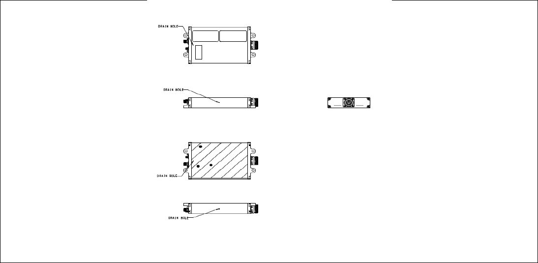
The physical configuration of the WDNU is described by drawing 96003702, part of which is
reproduced in Figure 1 below.
Figure 1 WDNU Top, Bottom and Side Views
4.3 WDNU Interfaces
The WDNU interfaces to the AHTMU through the electrical signals listed below. All connections are
through the main host connector J1.
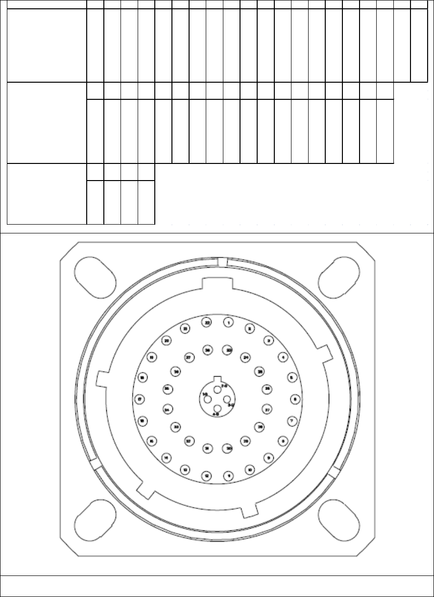
The pinout description for the main host to board connection interface is reproduced from SDRL C001
in Figure 2 below.
WDNU Users Manual
Page 10
Document Number 90001271
Figure 2 Main host to board connection pinout
PIN ID 12345678910 11 12 13 14 15 16 17 18 19 20
Amphenol Connector
Chassis Ground
28 VDC Popwer In 1
28 VDC Popwer In 2
28 VDC Popwer Return 1
28 VDC Popwer Return 2
Reserved 1
Reserved 2
Reserved 3
Reserved 4
Reserved 5
Reserved 6
Reserved 7
Reserved 8
Reserved 9
Reserved 10
Reserved 11
Reserved 12
Reserved 13
Reserved 14
Reserved 15
21 22 23 24 25 26 27 28 29 30 31 32 33 34 35 36 37 38
Amphenol Connector
Reserved 16
Reserved 17
Power On Discrete In
Power On Discrete Out
Shield/Ground
Reserved 20
Reserved 18
Reserved 19
RS-232 In
RS-232 Out
RS-232 Common
Not Connected
RS-422 Rx-(+)
RS-422 Rx-(-)
RS-422 Tx-(+)
RS-422 Tx-(-)
RS-422 Common
Not Connected
1-Q 2-Q 3-Q 4-Q
Center Quadrax
Ethernet RX-(+)
Ethernet TX-(-)
Ethernet RX-(-)
Ethernet TX-(+)

WDNU Users Manual
Page 11
Document Number 90001271
The connector J1 is an Amphenol part number TV00RQF-17-2-P. The mating connector is Amphenol
part number TV06RQF-17-2S.
4.3.1 Radio Power On Discrete
The radio power on signal is an Open/Ground discrete output from the Aircraft Health and Trend
Monitoring System used to turn the WDNU on or off. When asserted (grounded), power to the
WDNU is applied and the system is on. When de-asserted (open), the WDNU is off.
4.3.2 Radio Power Off Discrete
The radio power off signal is a 28VDC/Open discrete output from the WDNU to indicate whether the
WDNU is on or off. When the AHTMU turns the WDNU on with the radio power on discrete, the
radio power off discrete will be open to signal that the WDNU is on. When the WDNU is off this
signal will be pulled up to the aircraft supply voltage (28VDC nominal).
4.3.3 Ethernet Interface
The WDNU provides one Ethernet interface for communications with the AHTMU. The Ethernet
channels will support the IEEE-STD-802.3 10/100 Ethernet protocol with auto-negotiation. The cable
configuration specified is a crossover connection.
4.3.4 RS-232 Interface
A RS-232 serial communication interface has been included through the main connector to the
AHTMU. The settings for the RS-232 interface are shown in Figure 3.
Baud rate
115200
Number of data bits
8
Parity
None
Number of stop bits
1
Flow control
None
Figure 3 RS-232 port settings
4.3.5 RS-422 Interface
A RS-422 serial communication interface has been included through the main connector to the
AHTMU. The hardware interface has been designed and implemented on the WDNU, but this
interface is not supported by the current version of the operating system.

WDNU Users Manual
Page 12
Document Number 90001271
4.4 WDNU RF Interfaces
The WDNU has two external coaxial connections for the GSM and WiFi transceivers.
The two transmitters (WLAN/Cellular) cannot transmit at the same time. The unit has software control
to disable one transmitter when the other when is on.
4.4.1 WiFi Connection J2
Amphenol TNC connector – 031-2318
Antenna Type
Band
Gain (Average)
Titanis 2.4GHz B4844
2.4-2.5GHz
-1.0dBi
Note: Only this antenna or those with the same specification may be used with the WiFi connection.
4.4.2 GSM Connection J3
Amphenol SMA bulkhead connector – 901-9610
Antenna Type
Bands
Gain (Average)
Cellular
850MHz
1900MHz
2dBi
3dBi
Note: Only this antenna or those with the same specification may be used with the Cellular connection.
The device contains Cinterion’s HC25 (FCC ID: AIPHC25) and the module grants allows an antenna with
these specifications.

WDNU Users Manual
Page 13
Document Number 90001271
5. WDNU Functional Description
The WDNU is a gateway product which runs a server that allows the Aircraft Health and Trend
Monitoring Unit (AHTMU) to connect to a remote server over a secure connection. This section
describes some of the features of the WDNU, which are illustrated in the following figure.
CLI CHIP Web UI
Ethernet Wi-Fi Cellular
Python
Figure 4 Major functional components
5.1 Network Interfaces
The WDNU has Ethernet, Wi-Fi (802.11 b/g) and cellular (GSM 3G) network interfaces.
5.1.1 Ethernet
The Ethernet interface is configured with a static IP address of 192.168.114.1. Three main services are
provided on the Ethernet interface. These services are the Command-Line Interface (CLI), the Command
Handler Interface Protocol (CHIP), and the web user interface (web UI). The general use case for the
Ethernet port is the AHTMU communicates with the WDNU using CHIP.
5.1.2 Wi-Fi
The Wi-Fi interface supports the same three services as the Ethernet, which are the CLI, CHIP and web UI
services. The Wi-Fi interface is not enabled by default, but can be configured with any of the available
services on the Ethernet interface. For example, it can be configured to connect to an open wireless
network called TEST with the following CLI command:
#> set wlan channel=0 ssid=TEST authentication=open encryption=open
WDNU Users Manual
Page 14
Document Number 90001271
5.1.3 Cellular
The GSM cellular interface does not support the three services that are supported on the Ethernet and
Wi-Fi interfaces. It is used by the AHTMU to connect to a remote server when there are not any Wi-Fi
access points available or when the operator defines it as the primary communication links. The WDNU
contains two SIM card slots which are populated with an AT&T SIM and a Vodaphone SIM. The cellular
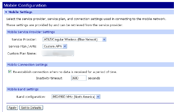
interface can be configured via the CLI, CHIP or the web UI services using either the Ethernet or Wi-Fi
interfaces. For example, Figure 5 illustrates the configuration of the cellular connection using the web
UI.
Figure 5 Mobile configuration
5.2 Services
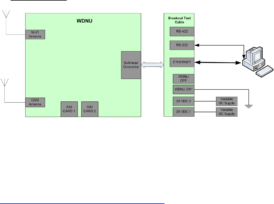
This section describes the services that are available on some of the network interfaces. To access these
interfaces an example of a basic test configuration setup is detailed below in figure 4.2-1
Equipment Needed:
1. WDNU board loaded with pre-installed SIM cards.
2. GSM antenna (see section 4.4 for antenna)
3. Wi-Fi antenna (see section 4.4 for antenna)
4. 2 DC power supplies
5. Mating cable for WDNU
6. Windows XP 32bit PC.
WDNU Users Manual
Page 15
Document Number 90001271
Connection Diagram:
Figure 4.2-1 – Example test configuration setup.
5.2.1 Command-Line Interface
The command-line interface provides commands for interacting with the WDNU. In addition to the
network interfaces, it is also available on the RS-232 serial interface. To use the commands you must
first access the WDNU using the Telnet protocol. For example, this can be done on a Windows machine
by opening a command prompt and entering telnet <WDNU IP address>. The commands and
their options are described in detail in the Command Reference guide for the Digi Connect Family.
Currently, the latest revision is available here:
http://ftp1.digi.com/support/documentation/90000566_H.pdf.
One of the key features available in the CLI is the ability to update the WDNU firmware. Refer to section
6.2 for more information.
5.2.2 Command Handler Interface Protocol
CHIP provides many of the same configuration and status commands that are available through the
command-line interface, but in a better defined and more consistent format. The available commands in
CHIP are defined in the Command Handler Interface Protocol Specification for the Wireless Data
Network Unit (YV2818). The CHIP service is available on UDP port 49000.
5.2.3 Web User Interface
The WDNU provides a collection of web pages for interacting with the WDNU. Much of the information
available on the web pages is also available through the CLI and CHIP services. The WDNU web UI is
available via HTTP on port 80 and can be accessed by a modern web browser like Internet Explorer,
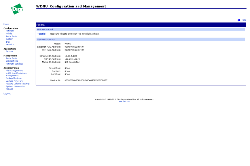
Firefox or Chrome. Figure 6 shows the home page for the web UI, and the sidebar shows many of the
other available web pages. Help is available on each page by clicking the Help link in the upper right
hand corner.
WDNU Users Manual
Page 16
Document Number 90001271
Figure 6 Web UI home page
5.3 Customization
Some parts of the WDNU can be customized with the WDNU Configuration and Management web page,
which is accessible via the Ethernet interface. The URL is http://<WDNU IP
address>/admin/customization.htm. Detailed customization information is available online at
http://ftp1.digi.com/support/documentation/90000734_B.pdf.
5.3.1 Factory Defaults
The WDNU is manufactured to contain a custom set of factory default configuration settings. The WDNU
uses these configurations every time it boots up. In other words, configuration changes are not
persisted from one boot to the next. The custom defaults include setting the Ethernet IP address to
192.168.114.1 and auto-running the WDNU Python application. The custom default settings are stored
in the defaults.rci file under the Customization Management section of the Customization
Administration web page. There is also a template defaults.rci file under the Customization Settings
section of the page. The template defaults.rci is the released defaults.rci for the WDNU, and can be
changed by uploading a new defaults.rci in the Customization Settings section.
5.3.2 Configuration File
Some of the settings related to the web UI can be customized using the Configuration File config.ini. A
template for this file is in the Customization Settings section of the Customization Administration web
page. This file includes settings for company and product information, tech support links and logo and
stylesheet resources.
5.3.3 Stylesheet
The CSS stylesheet used by the web UI can also be customized. A template stylesheet can be retrieved
from the Customization Settings section of the Customization Administration web page. The template
includes comments that describe where each group of style settings is used.

WDNU Users Manual
Page 17
Document Number 90001271
5.4 Python
The WDNU can be customized using the Python programming language. The Python interpreter can be
invoked from the CLI with the python command. A Python application was developed for the WDNU to
support the CHIP service. Python applications and other files can be loaded and viewed using the
Applications->Python page in the web UI. Much more information about Python on Digi products is
available on the web at http://www.digi.com/wiki/developer/index.php/Python_Wiki.
5.5 Startup Sequence
During boot the WDNU runs Power On Self Test (POST). This tests RAM, flash, and the validity of the
firmware image. It also runs BIT, where it tests the physical and logical connections to the Wi-Fi and
cellular interfaces and both SIM cards. BIT is described further in SDRL E005. The results of the BIT test
can be retrieved with the Transmit BIT Results CHIP command. Once booted, the Wi-Fi transceiver is off,
the cellular radio is on and the CHIP server application is running. The WDNU uses the factory default
settings on every boot, which is described more in section 5.3.
6. Detailed WDNU-specific description
6.1 CHIP
CHIP stands for the Command-Handler Interface Protocol. It was developed by GE for use on a
communication network between a client and server. It defines the protocol used for communication
between the host (such as the AHTMU) and the WDNU. It is defined in document YV2818.
6.1.1 CHIP Commands
CHIP contains a number of commands that can be used by the AHTMU to configure the WDNU, get BIT
status, and setup a VPN.
6.1.1.1 Generic Command
One of the commands is the generic command. This command can be used to execute a standard Digi
CLI command over the CHIP protocol. The command can be up to 1020 characters long and the response
is the same as if the command had been executed directly on the command line, including blank lines
and newline characters. The maximum size of the response data is 1022 characters and the response
will be truncated to 1022 characters if necessary.
6.1.1.2 Transmit BIT Status
This command reports on the BIT status of the Wi-Fi and cellular interfaces. Note that this command
switches the active SIM card.
6.1.1.3 Configure Wi-Fi
The WiFi radio can be configured by enabling the interface with the WiFi Interface Control command,
and then configuring the interface with the Set WiFi Mode and Set WiFi Tx Power commands.
WDNU Users Manual
Page 18
Document Number 90001271
6.1.1.4 Configure GSM
The GSM radio can be configured by enabling the interface with the GSM Interface Control command,
and then configuring it with the Set Active SIM Card command.
6.1.1.5 Configure VPN
The VPN can be set up by executing this CHIP command sequence:
1. Set Global VPN Mode
2. Set VPN Tunnel Options
3. Set VPN Phase 1 Proposal Options
4. Set VPN Phase 2 Proposal Options
5. Set VPN Interface ID.
6.1.2 Python and CHIP
The Python application implements the CHIP interface on the WDNU. This means the Python application
is responsible for accepting CHIP command messages, translating the commands to the native format,
executing the commands, and sending back the responses in CHIP ACK or data messages.
6.1.2.1 Python application
The Python application consists of three files: app.py, wdnuapp.zip and python.zip. The CHIP handling is
all in app.py. It basically consists of a CHIP server and a CHIP request handler. The CHIP server listens for
a CHIP client on UDP port 49000. When a UDP message is received, the server creates a thread to
execute the CHIP request handler. The CHIP request handler does general validation of the request
message, and then executes the appropriate CHIP command handler routine. Wdnuapp.zip contains
support libraries for running the app. Python.zip is the standard Digi python.zip that contains only
standard Python libraries which are used for running the app.
6.1.2.2 Logging
The Python application logs debugging information to the applogX.txt files. The files are limited in size to
32KB each, and to a total number of 6 files. The active log file is always applog.txt. When this file reaches
32KB, the oldest log file is removed, applog4.txt is renamed to applog5.txt, applog3.txt is renamed to
applog4.txt, etc… and a new applog.txt file is created. The application logs information in memory about
CHIP commands it receives, but the log messages are only written to the log files when an error message
is logged. This prevents unnecessary wear on the flash when there are no errors. An example of the log
messages is shown below.

WDNU Users Manual
Page 19
Document Number 90001271
6.2 LRU update procedure
The WDNU BOOT, POST and EOS firmware can be updated using the CLI or the web UI, but only on the
Ethernet interface. To update using the CLI, telnet to the WDNU and execute the boot command with
the load option, with host set to the address of a TFTP server accessible from the WDNU, and filename
set to the firmware update file. For example, if the TFTP server is at 10.35.1.50 and the firmware image
filename is 82002543, it can be loaded onto the WDNU with the following CLI command:
#> boot load 10.35.1.50:82002543
2010-07-09 13:19:17|========================================================
2010-07-09 13:19:17| Message 20: Executing message handler
2010-07-09 13:19:17| Message 20: 01 13 00 04
2010-07-09 13:19:17| Message 20: sequence number = 19
2010-07-09 13:19:17| Message 20: length = 4
2010-07-09 13:19:17| Message 20: message code = 1 (Command)
2010-07-09 13:19:17| Message 20: command = 0x0004 (Transmit Server Status)
2010-07-09 13:19:17| Message 20: long command valid = 0x010a (Report WiFi
Information and Statistics)
2010-07-09 13:19:17| Executing short running command handler
2010-07-09 13:19:17| 'Transmit Server Status' handler: Long running command
handler still running
2010-07-09 13:19:17| Sending: ACK - status: 'Busy' (5) msg: None
2010-07-09 13:19:17| Short running command handler execution complete