Digi XB3C1 XB3C1 User Manual
Digi International Inc XB3C1
UserManual.wiki
>
Digi
>
XB3C1 User Manual
user manual
Navigation menu
Upload a User Manual
Namespaces
Wiki Guide
HTML
PDF
Info
Views
User Manual
Discussion / Help
Navigation
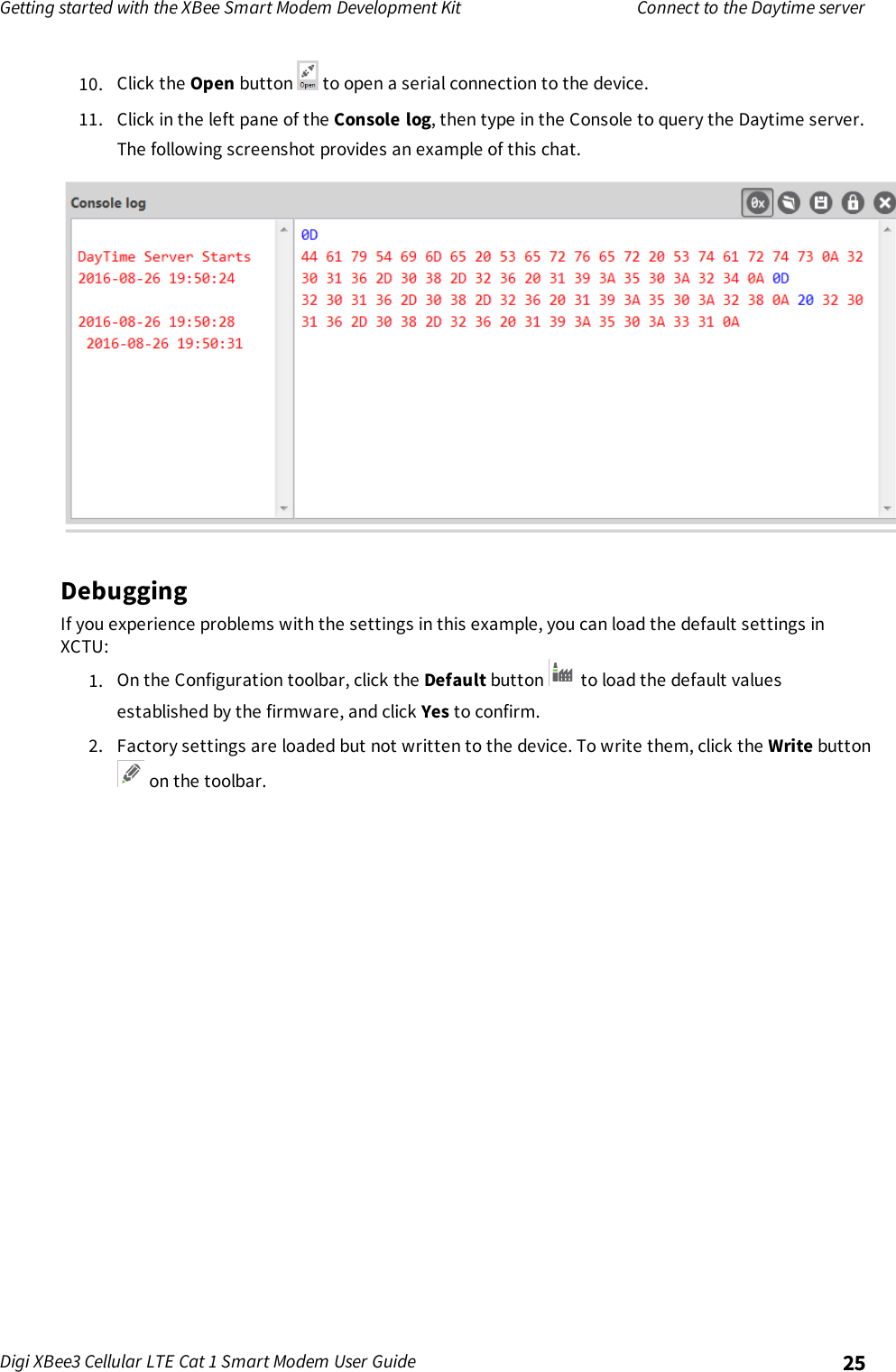
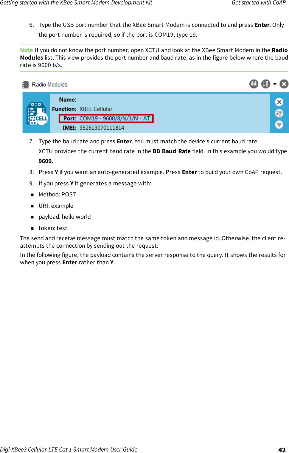
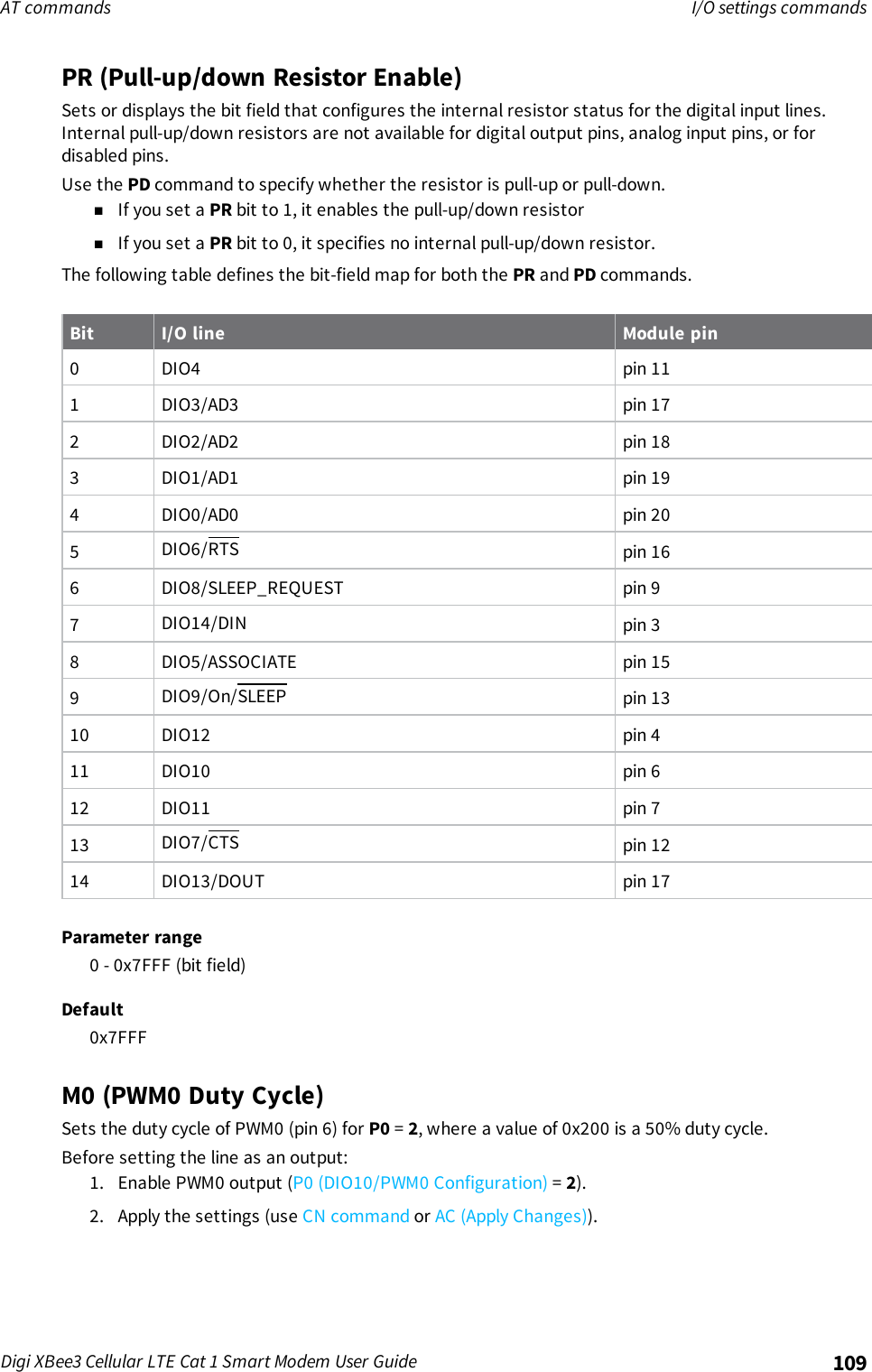
![Getting started with the XBee Smart Modem Development Kit Get started with MQTTDigi XBee3 Cellular LTE Cat 1 Smart Modem User Guide 32Fieldname DescriptionClient ID The length of the ID (in bytes) precedes the ID itself. Each client connecting to abroker must have a unique client ID. In the example, the ID is DIGI. When using thePaho MQTT Python libraries, a random alphanumeric ID is generated if you do notspecify an ID.The following table provides the CONNECT flag bits from byte 8, the CONNECT flags byte.CONNECT Flag Bit(s) Bit 7 Bit 6 Bit 5 Bit 4 Bit 3 Bit 2 Bit 1 Bit 0User name flag 0Password flag 0Will retain 0Will QoS 0 0Will flag 0Clean session 1Reserved 0Send a connect packetNow that you know what a connect packet looks like, you can send a connect packet to a broker andview the response. Open XCTU and click the Configuration working mode button.1. Ensure that the device is set up correctly with the SIM card installed and the antennasconnected as described in Connect the hardware.2. Open XCTU and click the Configuration working mode button.3. Add the XBee Smart Modem to XCTU; see Add a device.4. Select a device from the Radio Modules list. XCTU displays the current firmware settings forthat device.5. In the APfield, set Transparent Mode to [0] if it is not already and click the Write button.6. In the DL field, type the IP address of the broker you wish to use. This example uses198.41.30.241, which is the IP address for m2m.eclipse.org, a public MQTT broker.7. In the DE field, type 75B and set the port that the broker uses. This example uses 75B, becausethe default MQTT port is 1883 (0x75B).8. Once you have entered the required values, click the Write button to write the changes to theXBee Smart Modem.](https://usermanual.wiki/Digi/XB3C1/User-Guide-3720256-Page-32.png)
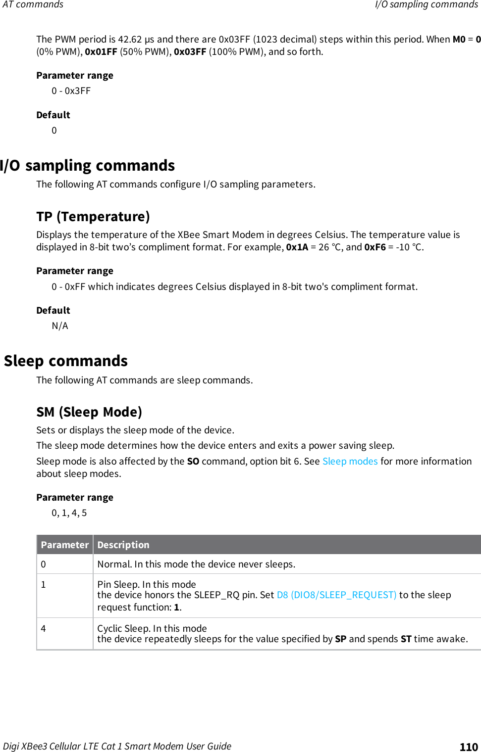
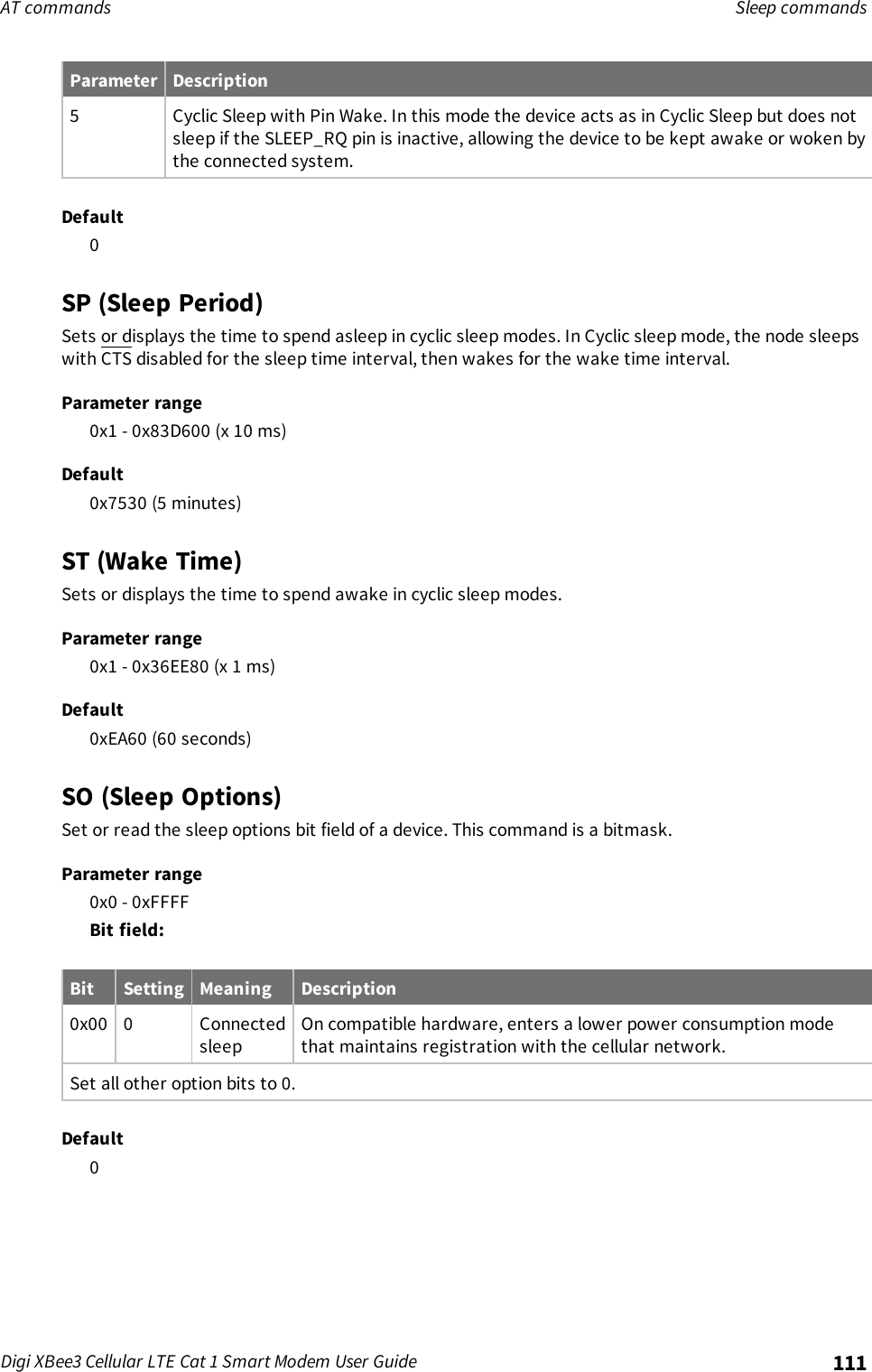
![Get started with MicroPython About MicroPythonDigi XBee3 Cellular LTE Cat 1 Smart Modem User Guide 47About MicroPythonMicroPython is an open-source programming language based on Python 3, with much of the samesyntax and functionality, but modified to fit on small devices with limited hardware resources, such asmicrocontrollers, or in this case, a cellular modem.Why use MicroPythonMicroPython enables on-board intelligence for simple sensor or actuator applications using digital andanalog I/O. MicroPython can help manage battery life. Cryptic readings can be transformed into usefuldata, excess transmissions can be intelligently filtered out, modern sensors and actuators can beemployed directly, and logic can glue inputs and outputs together in an intelligent way.For more information about MicroPython, see www.micropython.org.For more information about Python, see www.python.org.MicroPython on the XBee Smart ModemThe XBee Smart Modem has MicroPython running on the device itself. You can access a MicroPythonprompt from the XBee Smart Modem when you install it in an appropriate development board (XBDBor XBIB), and connect it to a computer via a USB cable.Note MicroPython does not work with SPI.The examples in this guide assume:nYou have XCTU on your computer. See Configure the device using XCTU.nYou have a terminal program installed on your computer. We recommend using the Use theMicroPython Terminal in XCTU. This requires XCTU 6.3.7 or higher.nYou have an XBee Smart Modem installed in an appropriate development board such as anXBIB-U-DEV or an XBIB-2.Note Most examples in this guide require the XBIB-U-DEV board.nThe XBee Smart Modem is connected to the computer via a USB cable and XCTU recognizes it.nThe board is powered by an appropriate power supply, 12 VDC and at least 1.1 A.Use XCTU to enter the MicroPython environmentTo use the XBee Smart Modem in the MicroPython environment:1. Use XCTU to add the device(s); see Configure the device using XCTU and Add a device.2. The XBee Smart Modem appears as a box in the Radio Modules information panel. Eachmodule displays identifying information about itself.3. Click this box to select the device and load its current settings.4. To set the device's baud rate to 115200 b/s, in the BD field select 115200 [7] and click theWrite button . We recommend using flow control to avoid data loss, especially when pastinglarge amounts of code/text.](https://usermanual.wiki/Digi/XB3C1/User-Guide-3720256-Page-47.png)
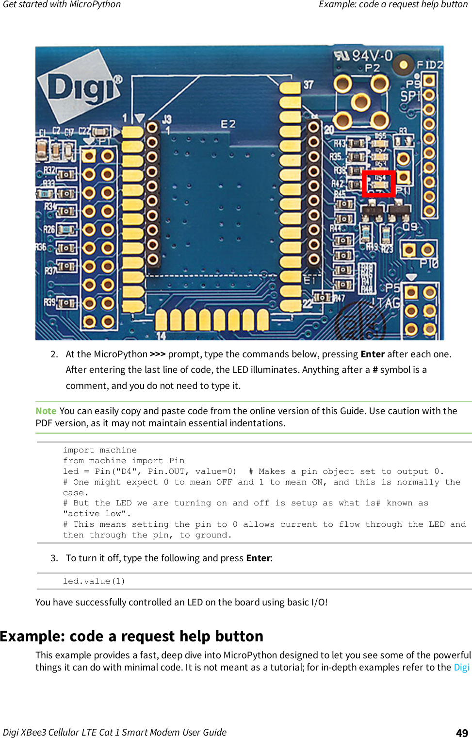
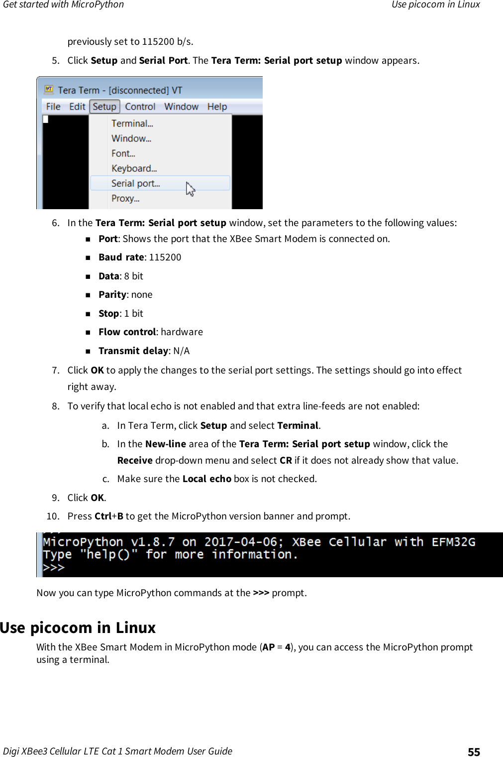
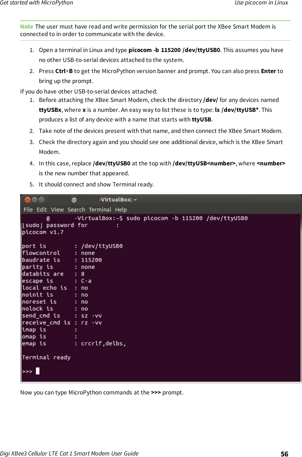
![Get started with MicroPython Use the MicroPython Terminal in XCTUDigi XBee3 Cellular LTE Cat 1 Smart Modem User Guide 485. To put the XBee Smart Modem into MicroPython mode, in the APfield select MicroPythonREPL [4] and click the Write button .6. Note what COM port(s) the XBee Smart Modem is using, because you will need this informationwhen you use terminal communication.Use the MicroPython Terminal in XCTUYou can use the MicroPython Terminal to communicate with the XBee Smart Modem when it is inMicroPython mode.1This requires XCTU 6.3.7 or higher. To enter MicroPython mode, follow the stepsin Use XCTU to enter the MicroPython environment. To use the MicroPython Terminal:1. Click the Tools drop-down menu and select MicroPython Terminal. The terminal opens.2. Click Open.3. In the Select the Serial/USB port area, click the COM port that the device uses.4. Verify that the baud rate and other settings are correct.5. Click OK. The Open icon changes to Close , indicating that the device is properly connected.You can now type or paste MicroPython code in the terminal.Example: hello world1. At the MicroPython >>> prompt, type the Python command: print("Hello, World!")2. Press Enter to execute the command. The terminal echos back Hello, World!.Example: turn on an LED1. Note the DS4 LED on the XBIB board. The following image highlights it in a red box. The LED isnormally off.1See Other terminal programs if you do not use the MicroPython Terminal in XCTU.](https://usermanual.wiki/Digi/XB3C1/User-Guide-3720256-Page-48.png)
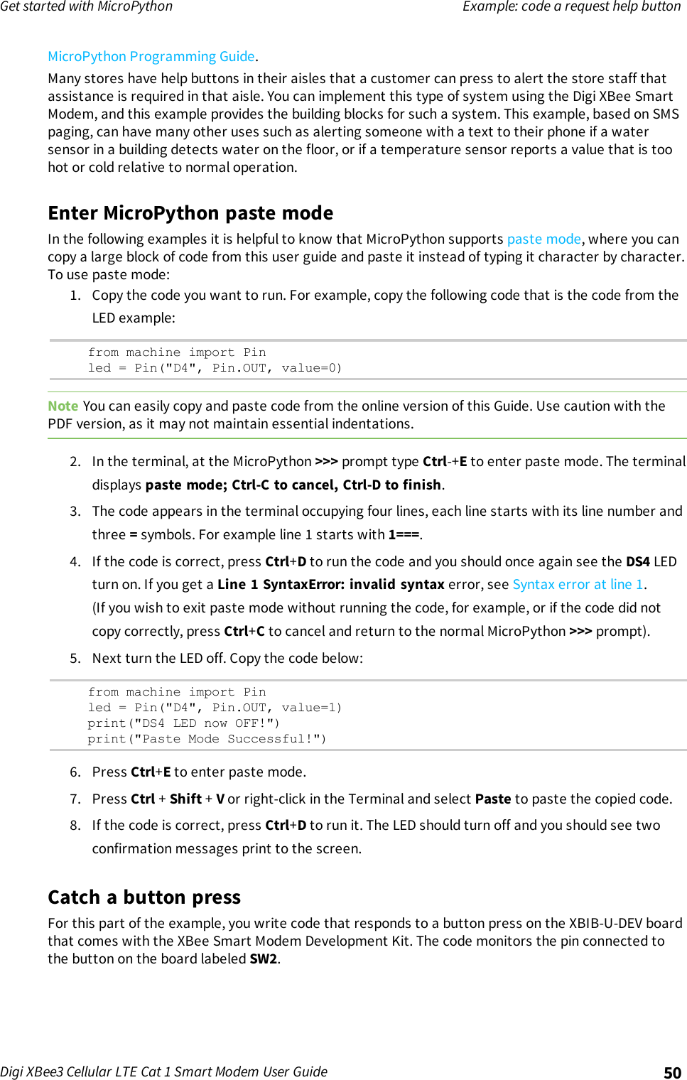
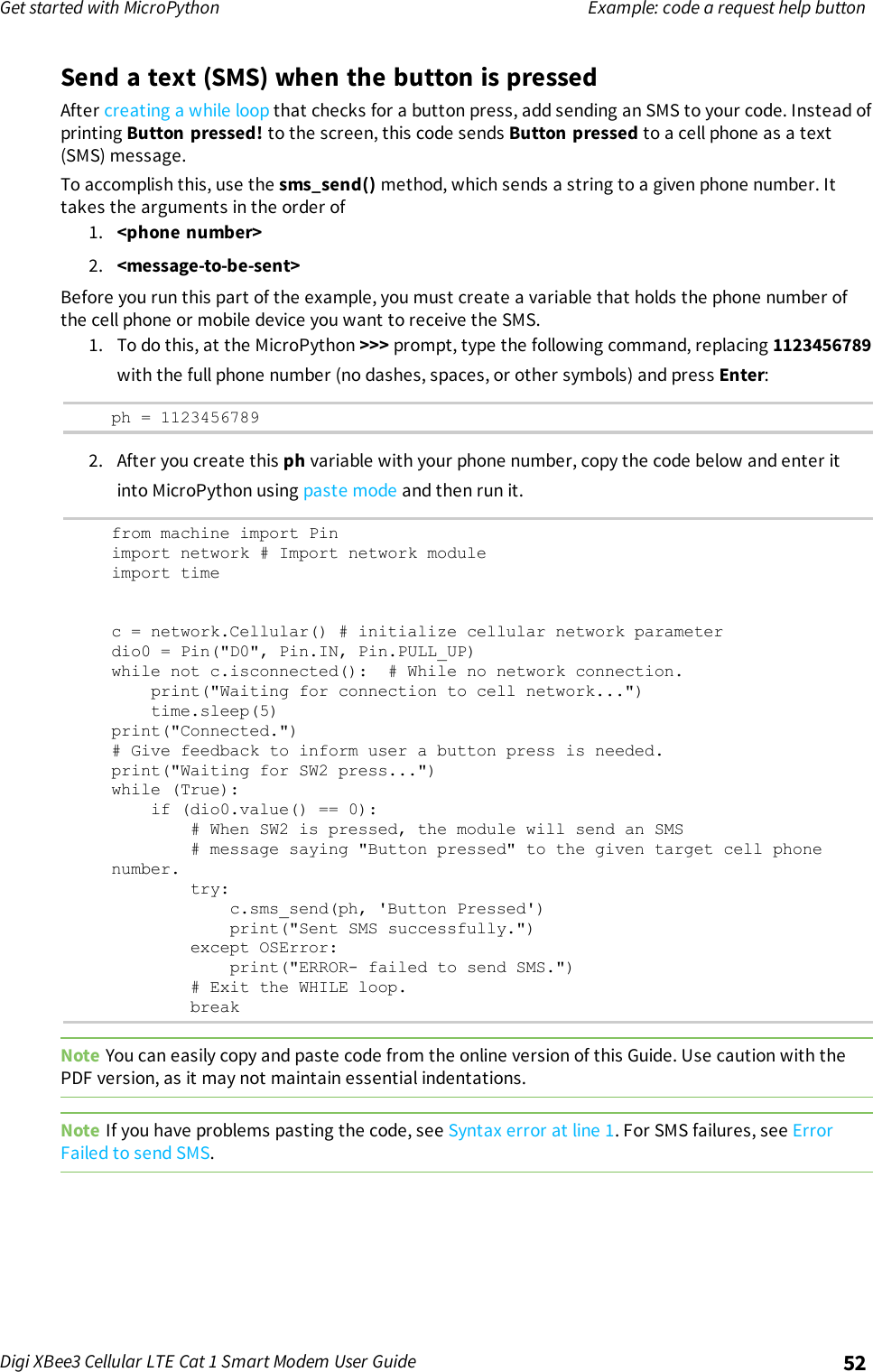
![Get started with MicroPython Example: code a request help buttonDigi XBee3 Cellular LTE Cat 1 Smart Modem User Guide 53Add the time the button was pressedAfter you add the ability to send an SMS to the code, add functionality to insert the time at which thebutton was pressed into the SMS that is sent. To accomplish this:1. Create a UDP socket with the socket() method.2. Save the IP address and port of the time server in the addr variable.3. Connect to the time server with the connect() method.4. Send hello to the server to prompt it to respond with the current date and time.5. Receive and store the date/time response in the buf variable.6. Send an SMSin the same manner as before using the sms_send() method, except that you addthe time into the SMS message, such that the message reads: [Button pressed at: YYYY-MM-DD HH:MM:SS]To verify that your phone number is still in the memory, at the MicroPython >>> prompt, type ph andpress Enter.If MicroPython responds with your number, copy the following code and enter it into MicroPythonusing paste mode and then run it. If it returns an error, enter your number again as shown in Send atext (SMS) when the button is pressed. With your phone number in memory in the ph variable, copythe code below and enter it into MicroPython using paste mode and then run it.from machine import Pinimport networkimport usocketimport timec = network.Cellular()dio0 = Pin("D0", Pin.IN, Pin.PULL_UP)while not c.isconnected(): # While no network connection.print("Waiting for connection to cell network...")time.sleep(5)print("Connected.")# Give feedback to inform user a button press is needed.print("Waiting for SW2 press...")while (1):if (dio0.value() == 0):# When button pressed, now the module will send "Button Press" AND# the time at which it was pressed in an SMS message to the given# target cell phone number.socketObject = usocket.socket(usocket.AF_INET, usocket.SOCK_DGRAM)# Connect the socket object to the web server specified in"address".addr = ("52.43.121.77", 10002)socketObject.connect(addr)bytessent = socketObject.send("hello")print("Sent %d bytes on socket" % bytessent)buf = socketObject.recv(1024)# Send message to the given number. Handle error if it occurs.try:c.sms_send(ph, 'Button Pressed at: ' + str(buf))print("Sent SMS successfully.")except OSError:print("ERROR- failed to send SMS.")](https://usermanual.wiki/Digi/XB3C1/User-Guide-3720256-Page-53.png)
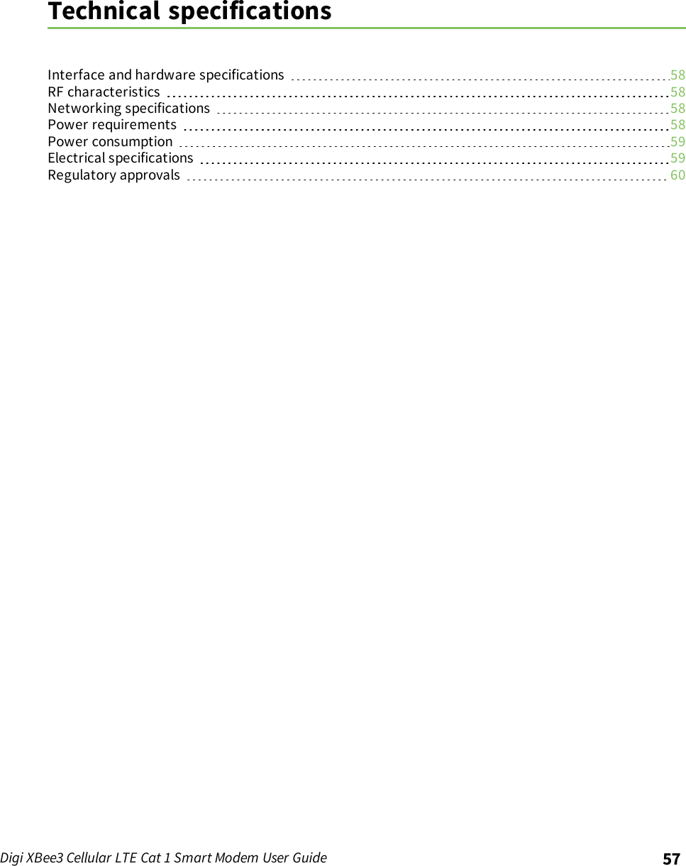
![Get started with MicroPython Exit MicroPython modeDigi XBee3 Cellular LTE Cat 1 Smart Modem User Guide 54# Exit the WHILE loop.breakNote You can easily copy and paste code from the online version of this Guide. Use caution with thePDF version, as it may not maintain essential indentations.Now you have a system based on the XBee Smart Modem that sends an SMS in response to a certaininput, in this case a simple button press.Note If you have problems pasting the code, see Syntax error at line 1. For SMS failures, see ErrorFailed to send SMS.Exit MicroPython modeTo exit MicroPython mode:1. In the XCTU MicroPython Terminal, click the green Close button .2. Click Close at the bottom of the terminal to exit the terminal.3. In XCTU's Configuration working mode , change AP API Enable to another mode and clickthe Write button . We recommend changing to Transparent mode [0], as most of theexamples use this mode.Other terminal programsIf you do not use the MicroPython Terminal in XCTU, you can use other terminal programs tocommunicate with the XBee Smart Modem. If you use Microsoft Windows, follow the instructions forTera Term, if you use Linux, follow the instructions for picocom. To download these programs:nTera Term for Windows; see https://ttssh2.osdn.jp/index.html.en.nPicocom for Linux; see https://developer.ridgerun.com/wiki/index.php/Setting_up_Picocom_-_Ubuntu and for the source code and in-depth information https://github.com/npat-efault/picocom.Tera Term for WindowsWith the XBee Smart Modem in MicroPython mode (AP =4), you can access the MicroPython promptusing a terminal.1. Open Tera Term. The Tera Term: New connection window appears.2. Click the Serial radio button to select a serial connection.3. From the Port: drop-down menu, select the COM port that the XBee Smart Modem isconnected to.4. Click OK. The COMxx - Tera Term VT terminal window appears and Tera Term attempts toconnect to the device at a baud rate of 9600 b/s. The terminal will not allow communicationwith the device since the baud rate setting is incorrect. You must change this rate as it was](https://usermanual.wiki/Digi/XB3C1/User-Guide-3720256-Page-54.png)
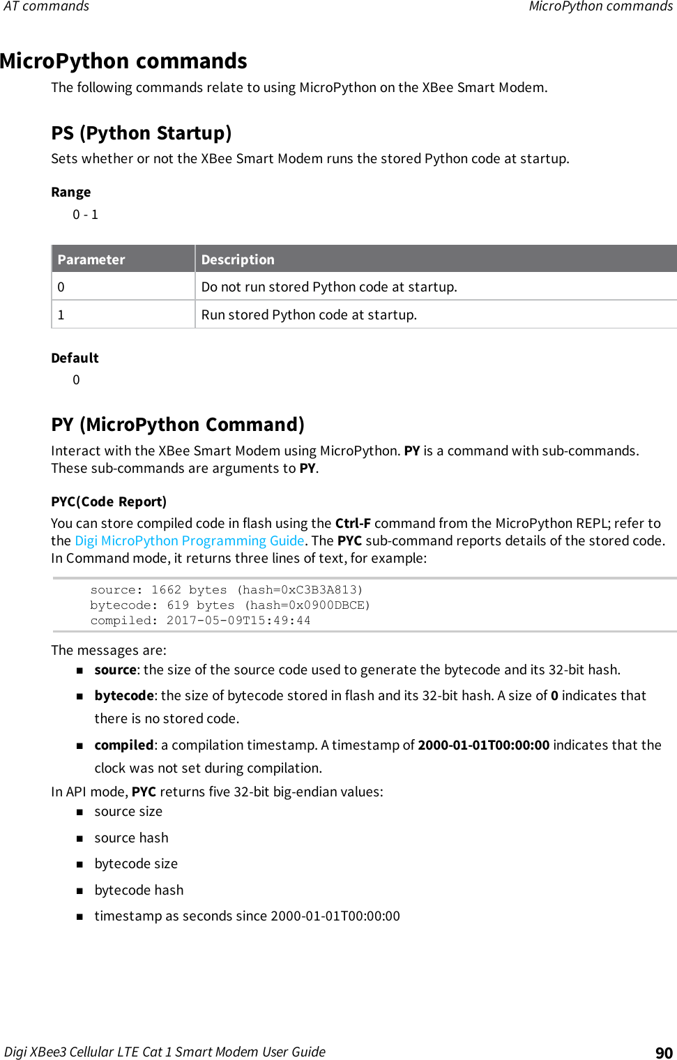
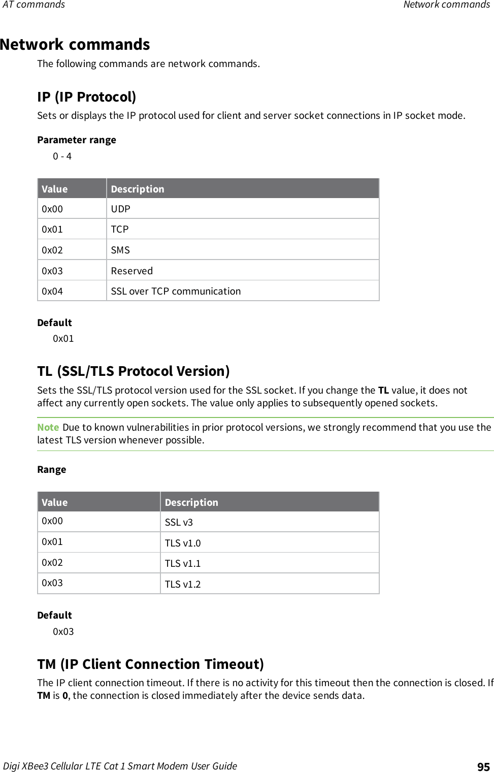
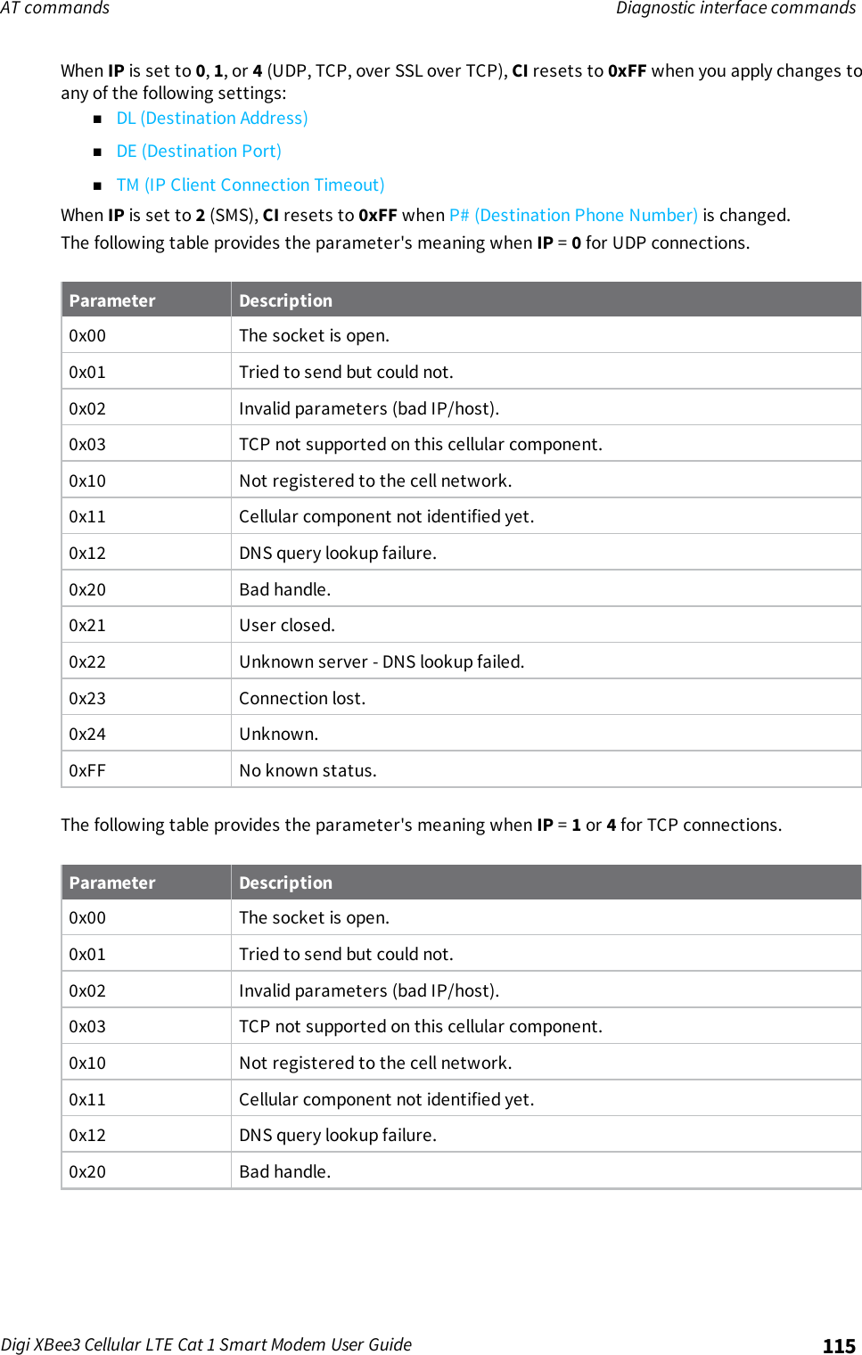
![AT commands Cellular commandsDigi XBee3 Cellular LTE Cat 1 Smart Modem User Guide 93IM (IMEI)Reads the device's International Mobile Equipment Identity (IMEI).Parameter rangeN/ADefaultSet in the factoryMN (Operator)Reads the network operator on which the device is registered.Parameter rangeN/ADefaultAT&TMV (Modem Firmware Version)Read the firmware version string for cellular component communications. See the related VR(Firmware Version) command.Parameter rangeN/ADefaultSet in the currently loaded firmwareDB (Cellular Signal Strength)Reads the absolute value of the current signal strength to the cell tower in dB. If DB is blank, the XBeeSmart Modem has not received a signal strength from the cellular component.Parameter range0x71 - 0x33 (-113 dBm to -51 dBm) [read-only]DefaultN/AAN (Access Point Name)Specifies the packet data network that the modem uses for Internet connectivity. This information isprovided by your cellular network operator. After you set this value, applying changes with AC (ApplyChanges) or CN (Exit Command mode) triggers a network reset.Parameter range1 - 100 ASCII characters](https://usermanual.wiki/Digi/XB3C1/User-Guide-3720256-Page-93.png)
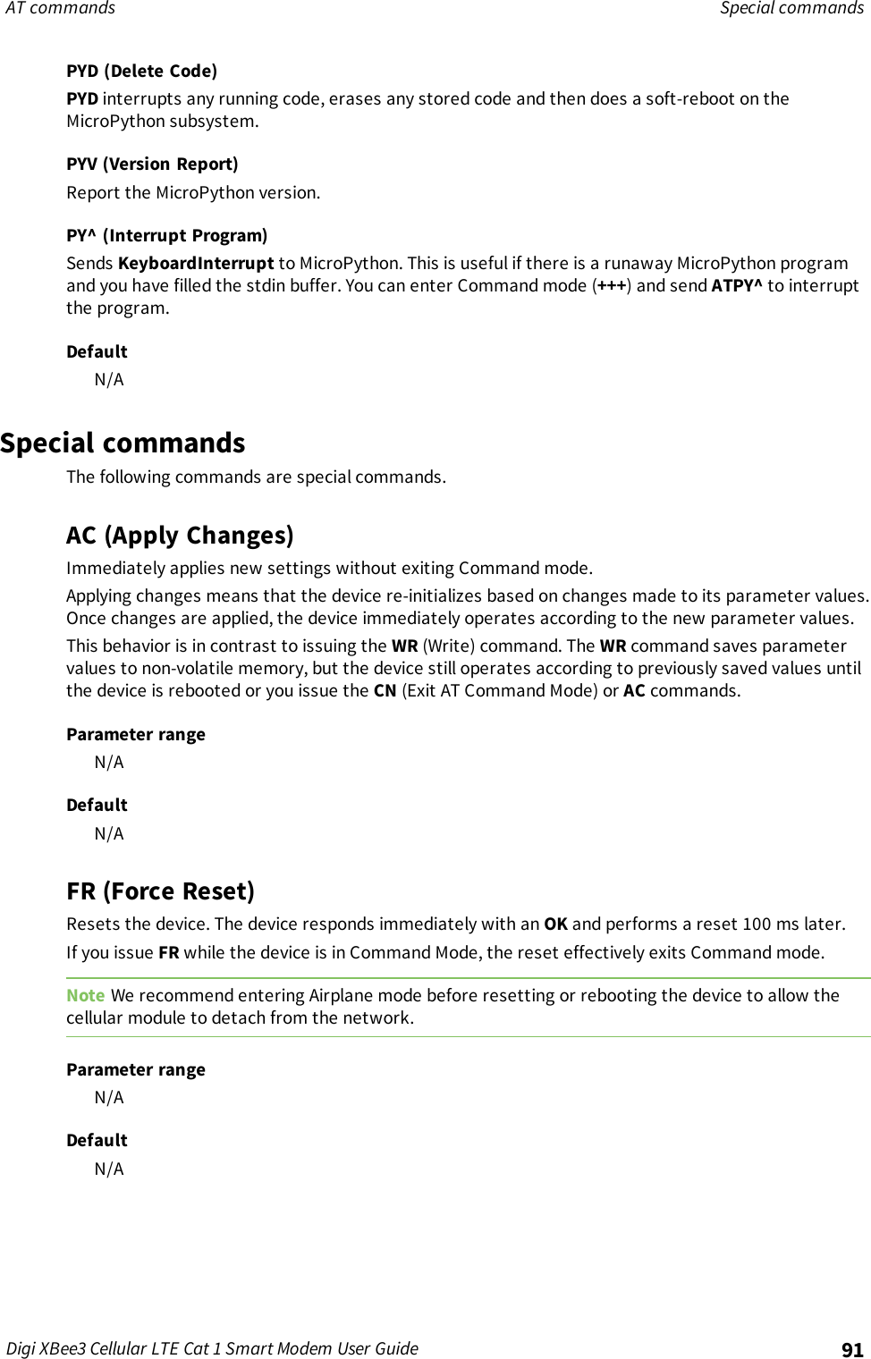
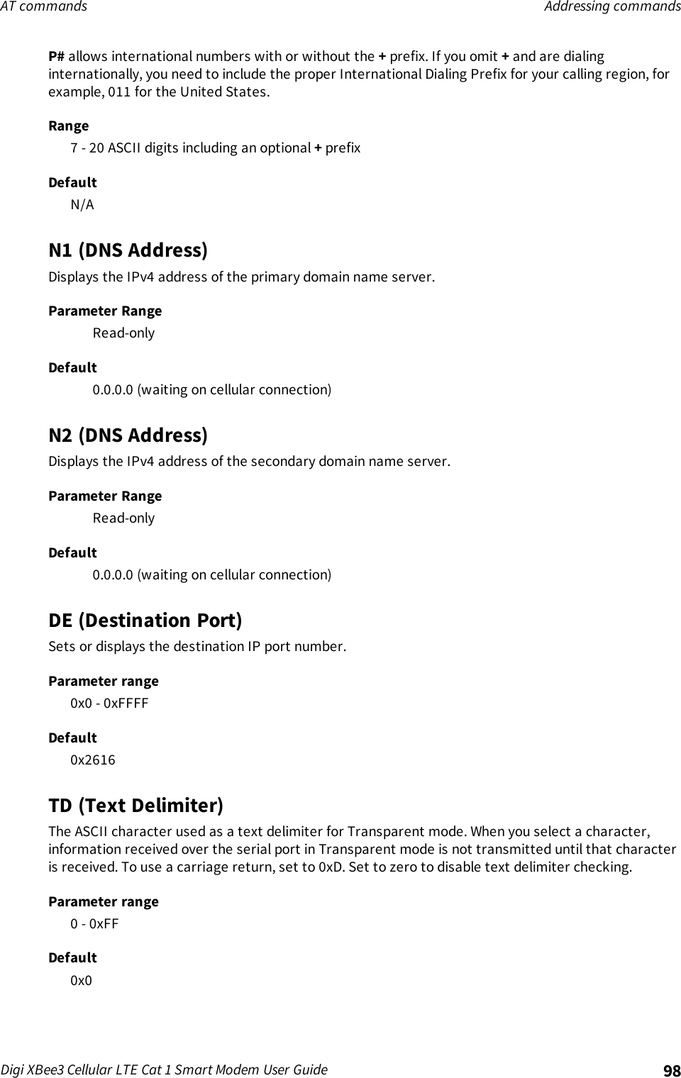
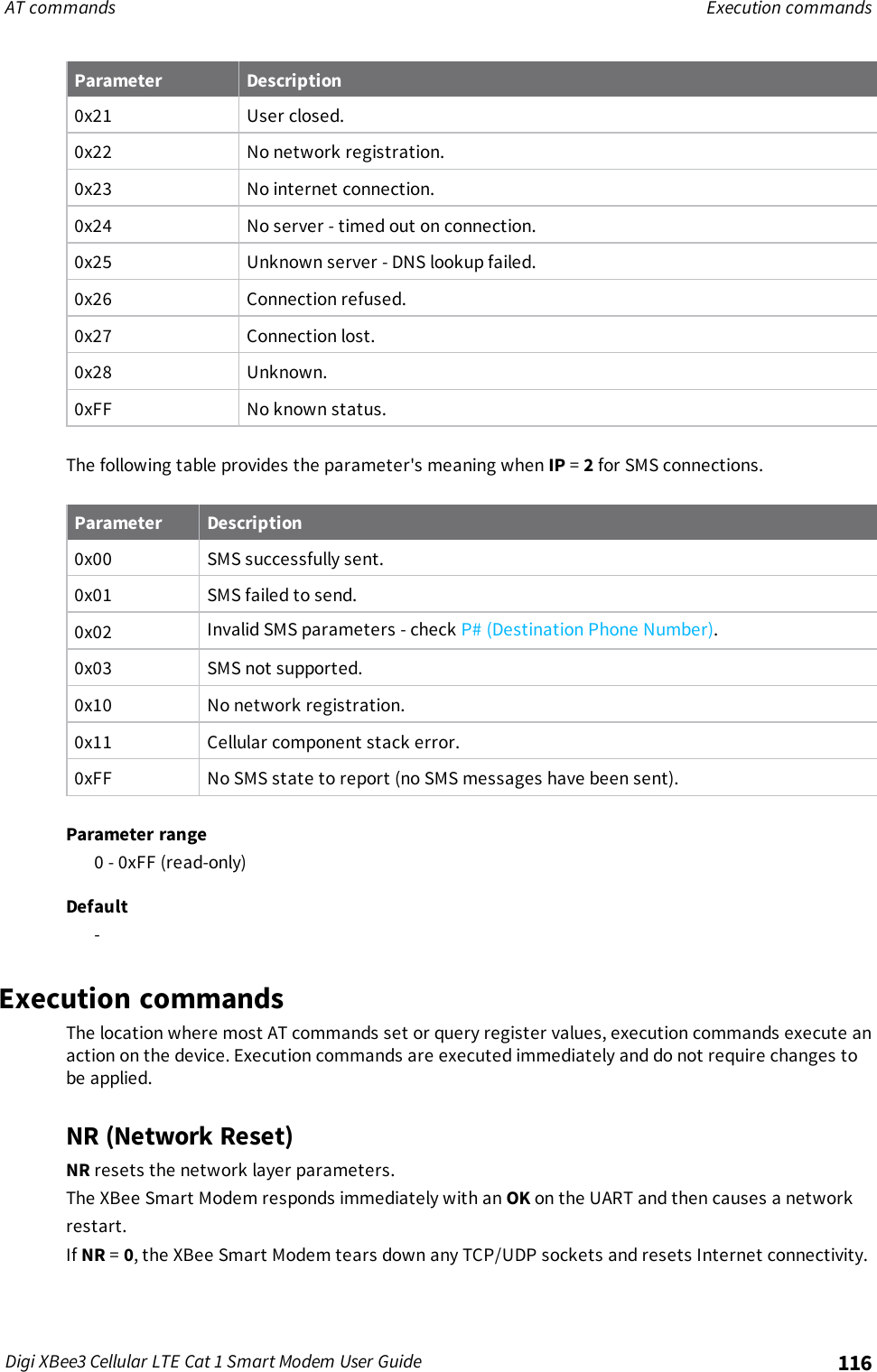
![AT commands Network commandsDigi XBee3 Cellular LTE Cat 1 Smart Modem User Guide 96If you change the TM value while in Transparent Mode, the current connection is immediately closed.Upon the next transmission, the TM value applies to the newly created socket.If you change the TM value while in API Mode, the value only applies to subsequently opened sockets.Parameter range0 - 0xFFFF [x 100 ms]Default0xBB8 (5 minutes)TS (IP Server Connection Timeout)The IP server connection timeout. If no activity for this timeout then the connection is closed. Whenset to 0the connection is closed immediately after data is sent.]Parameter Range10 - 0xFFFF; (x 100 ms)Default3000DO (Device Options)Enables and disables special features on the XBee Smart Modem according to the following table.Bit 0 - Remote Manager supportIf the XBee Smart Modem cannot establish a connection with Remote Manager , it waits 30 secondsbefore trying again. On each successive connection failure, the wait time doubles (60 seconds, 120,240, and so on) up to a maximum of 1 hour. This time resets to 30 seconds once the connection toRemote Manager succeeds or if the device is reset.Bits 1 - 7ReservedRange0x00 - 0x07Value Description0x00 Disable Remote Manager support.0x01 Enable Remote Manager support.Default0x01EQ (Device Cloud FQDN)Sets or display the fully qualified domain name of the Remote Manager server.](https://usermanual.wiki/Digi/XB3C1/User-Guide-3720256-Page-96.png)
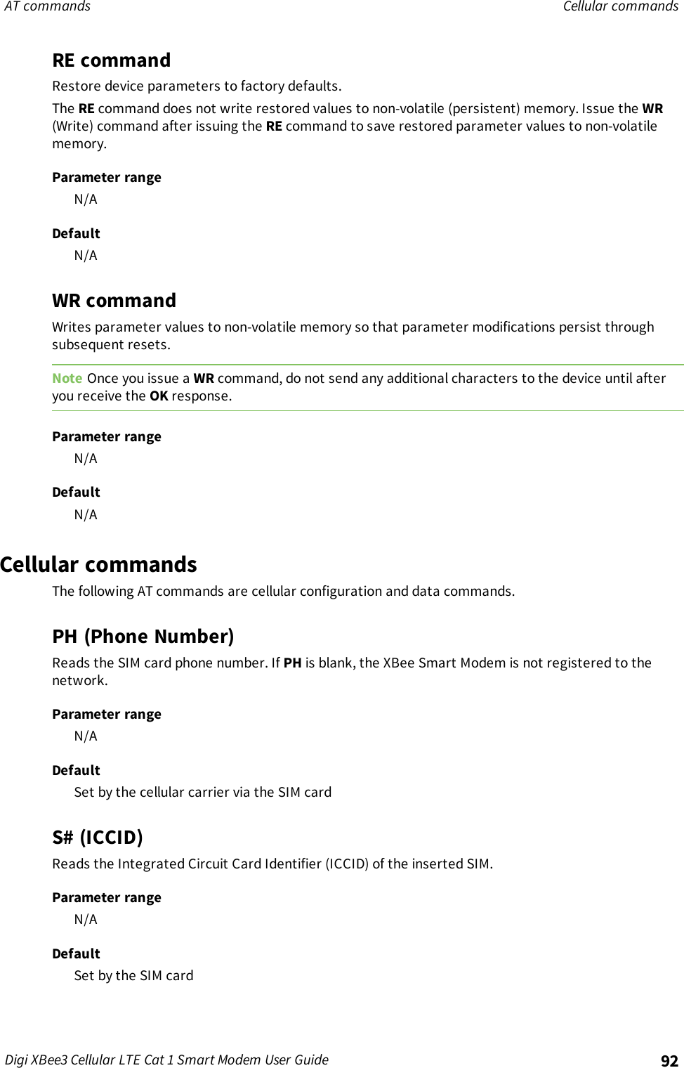
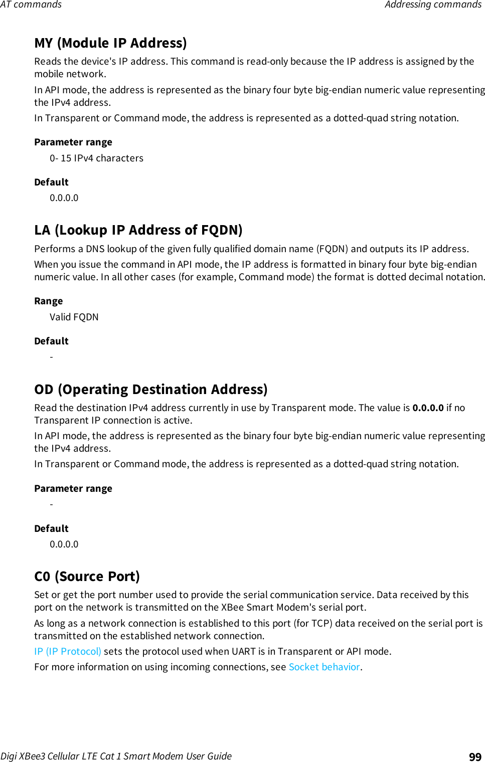
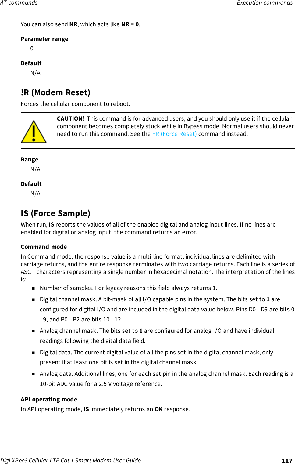
![AT commands Addressing commandsDigi XBee3 Cellular LTE Cat 1 Smart Modem User Guide 97RangeFrom 0 through 63 ASCII characters.Defaultmy.devicecloud.comAddressing commandsThe following AT commands are addressing commands.SH (Serial Number High)The upper digits of the unique International Mobile Equipment Identity (IMEI) assigned to this device.Parameter range0 - 0xFFFFFFFF [read-only]DefaultN/ASL (Serial Number Low)The lower digits of the unique International Mobile Equipment Identity (IMEI) assigned to this device.Parameter range0 - 0xFFFFFFFF [read-only]DefaultN/ADL (Destination Address)The destination IPv4 address or fully qualified domain name.To set the destination address to an IP address, the value must be a dotted quad, for exampleXXX.XXX.XXX.XXX.To set the destination address to a domain name, the value must be a legal Internet host name, forexample remotemanager.digi.comParameter range0 - 128 ASCII charactersDefault0.0.0.0P# (Destination Phone Number)Sets or displays the destination phone number used for SMS when IP (IP Protocol) =2. Phone numbersmust be fully numeric, 7 to 20 ASCIIdigits, for example:8889991234.](https://usermanual.wiki/Digi/XB3C1/User-Guide-3720256-Page-97.png)
![AT commands Command mode optionsDigi XBee3 Cellular LTE Cat 1 Smart Modem User Guide 112Command mode optionsThe following commands are Command mode option commands.CC (Command Sequence Character)The character value the device uses to enter Command mode.The default value (0x2B) is the ASCII code for the plus (+) character. You must enter it three timeswithin the guard time to enter Command mode. To enter Command mode, there is also a requiredperiod of silence before and after the command sequence characters of the Command modesequence (GT +CC +GT). The period of silence prevents inadvertently entering Command mode.Parameter range0 - 0xFFDefault0x2B (the ASCII plus character:+)CT (Command Mode Timeout)Sets or displays the Command mode timeout parameter. If a device does not receive any validcommands within this time period, it returns to Idle mode from Command mode.Parameter range2 - 0x1770 (x 100 ms)Default0x64 (10 seconds)GT (Guard Times)Set the required period of silence before and after the command sequence characters of theCommand mode sequence (GT +CC +GT). The period of silence prevents inadvertently enteringCommand mode.Parameter range0x2 - 0x6D3 (x 1 ms)Default0x3E8 (one second)Firmware version/information commandsThe following AT commands are firmware version/information commands.VR (Firmware Version)Reads the firmware version on a device.Parameter range0 - 0xFFFF [read-only]](https://usermanual.wiki/Digi/XB3C1/User-Guide-3720256-Page-112.png)
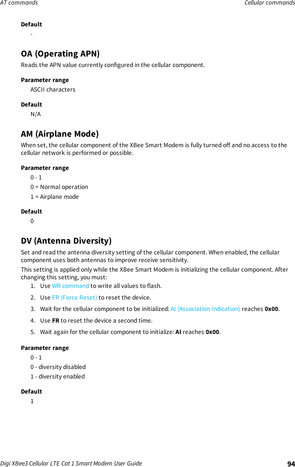
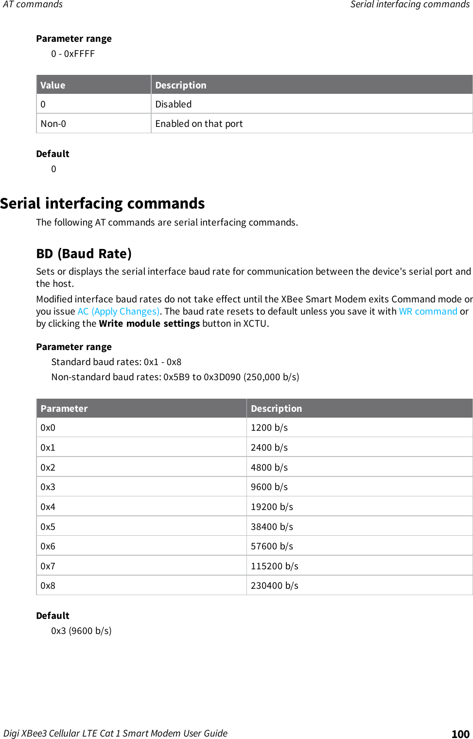
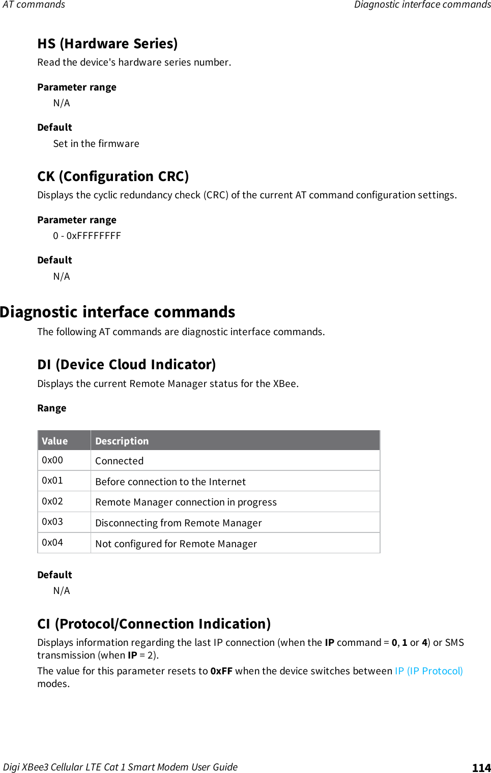
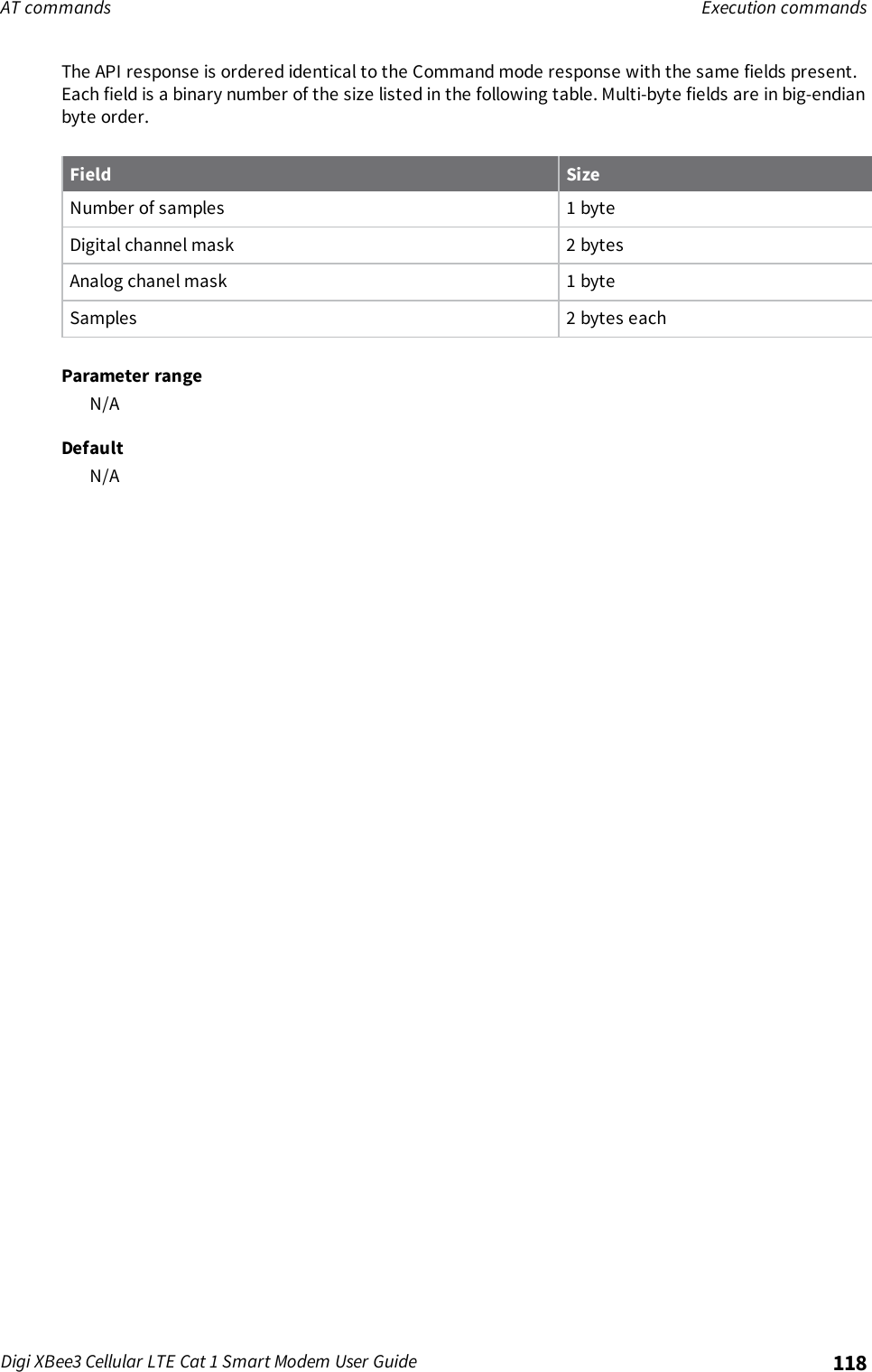
![AT commands Firmware version/information commandsDigi XBee3 Cellular LTE Cat 1 Smart Modem User Guide 113DefaultSet in firmwareVL (Verbose Firmware Version)Shows detailed version information including the application build date and time.Parameter rangeN/ADefaultSet in firmwareHV (Hardware Version)Display the hardware version number of the device.Parameter range0 - 0xFFFF [read-only]DefaultSet in firmwareAI (Association Indication)Reads the Association status code to monitor association progress. The following table provides thestatus codes and their meanings.Statuscode Meaning0x00 Connected to the Internet.0x22 Registering to cellular network.0x23 Connecting to the Internet.0x24 The cellular component is missing, corrupt, or otherwise in error. The cellularcomponent requires a new firmware image.0x25 Cellular network registration denied.0x2A Airplane mode.0x2B USB Direct active.0x2F Bypass mode active.0xFF Initializing.Parameter range0 - 0xFF [read-only]DefaultN/A](https://usermanual.wiki/Digi/XB3C1/User-Guide-3720256-Page-113.png)
![Socket behavior API mode behavior for outgoing TCP and SSL connectionsDigi XBee3 Cellular LTE Cat 1 Smart Modem User Guide 1341. Set AP (API Enable) to Transparent Mode [0].2. Set C0 (Source Port) to the value of the TCP port that the device listens on.3. Click the Write button .API mode behavior for outgoing TCP and SSL connectionsTo initiate an outgoing TCP or SSL connection to a remote host, send a Transmit (TX) Request: IPv4 -0x20 frame to the XBee Smart Modem's serial port specifying the destination address and destinationport for the remote host; the data is optional and the source port is 0.If the connection is disconnected at any time, send a Transmit TX Request frame to trigger a newconnection attempt.To send data over this connection use the Transmit (TX) Request: IPv4 - 0x20.The device sends a Transmit (TX) Status - 0x89 frame in reply to the Transmit TX Request indicatingthe status of the request. A status of 0indicates the connection and/or data was successful and anon-zero value indicates a failure.Any data received on the connection is sent out the XBee Smart Modem's serial port as a Receive RXframe.A connection is closed when:nThe remote end closes the connection.nNo data is sent or received for longer than the socket timeout set by TM (IP Client ConnectionTimeout).nA Transmit TX Request is sent with the CLOSE flag set.API mode behavior for outgoing UDP dataTo send a UDP datagram to a remote host, send a Transmit (TX) Request: IPv4 - 0x20 frame to theXBee Smart Modem's serial port specifying the destination address and destination port of theremote host. If you use a source port of 0, the device creates a new socket for the purpose of sendingto the remote host. The XBee Smart Modem supports a finite number of sockets, so if you need tosend to many destinations:1. The socket must be closed after use.or2. You must use the socket specified by the C0 (Source Port) setting.To use the socket specified by the C0 setting, in the Transmit TX request frame use a source port thatmatches the value configured for the C0 setting.The device sends a Transmit (TX) Status - 0x89 frame in reply to the Transmit TX Request to indicatethe status of the request. A status of 0indicates the data was successfully sent out of the device anda non-zero value indicates a failure.Any data received on the UDP socket is sent out the XBee Smart Modem's serial port as a Receive (RX)Packet: IPv4 - 0xB0 frame.A UDP socket is closed when:nNo data has been sent or received for longer than the socket timeout set by TM (IP ClientConnection Timeout).nA transmit TX Request is sent with the CLOSE flag set.](https://usermanual.wiki/Digi/XB3C1/User-Guide-3720256-Page-134.png)