Digi XBEE09P XBee-PRO 900 OEM RF Module User Manual XBEE
Digi International Inc XBee-PRO 900 OEM RF Module XBEE
UserManual.wiki
>
Digi
>
XBEE09P User Manual
User Manual
Navigation menu
Upload a User Manual
Namespaces
Wiki Guide
HTML
PDF
Info
Views
User Manual
Discussion / Help
Navigation
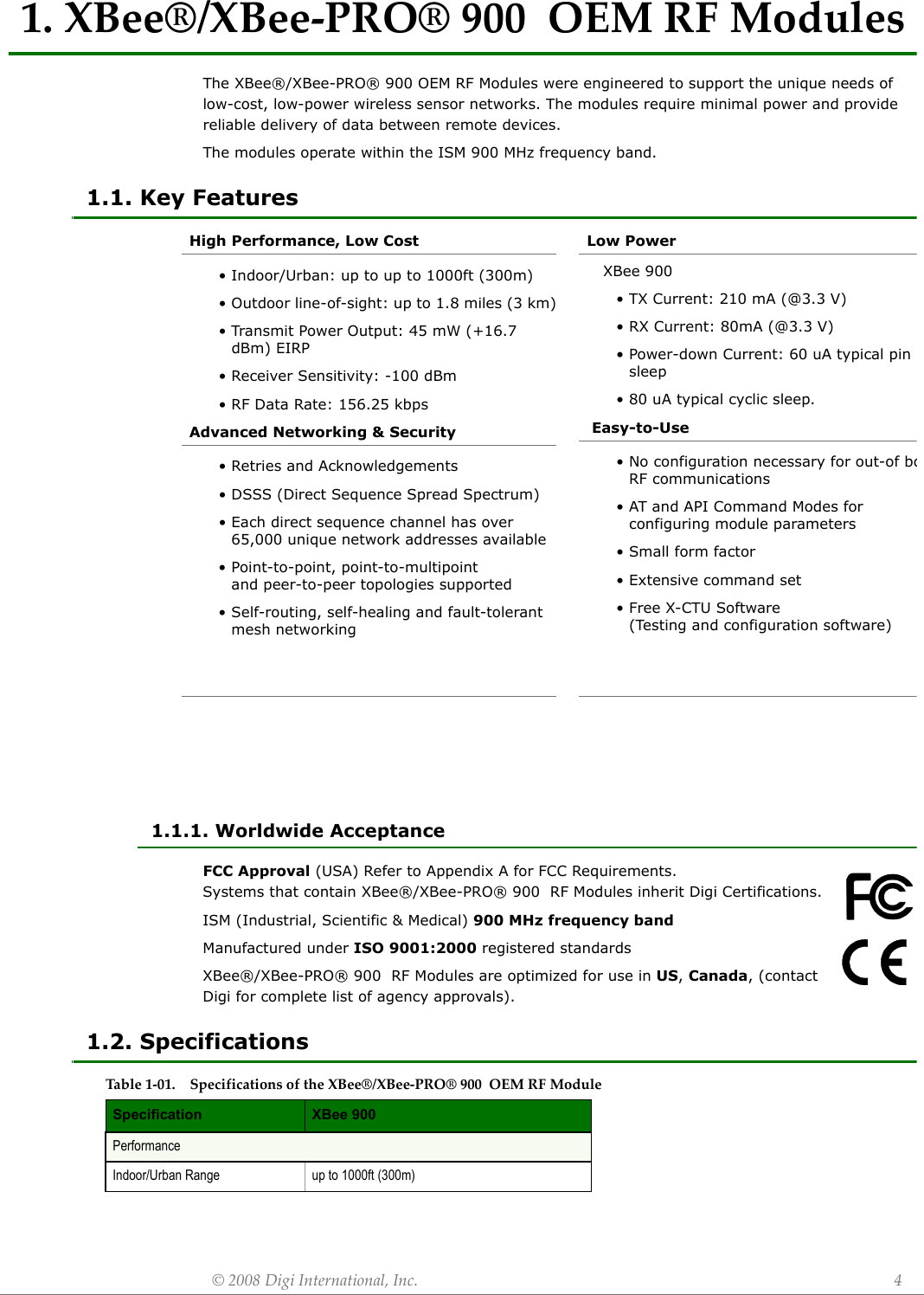
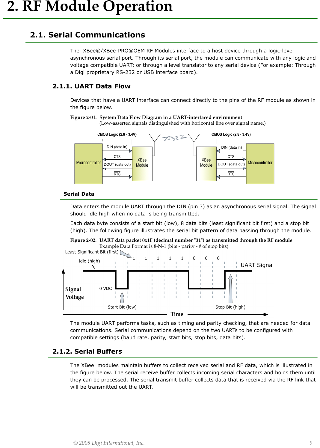
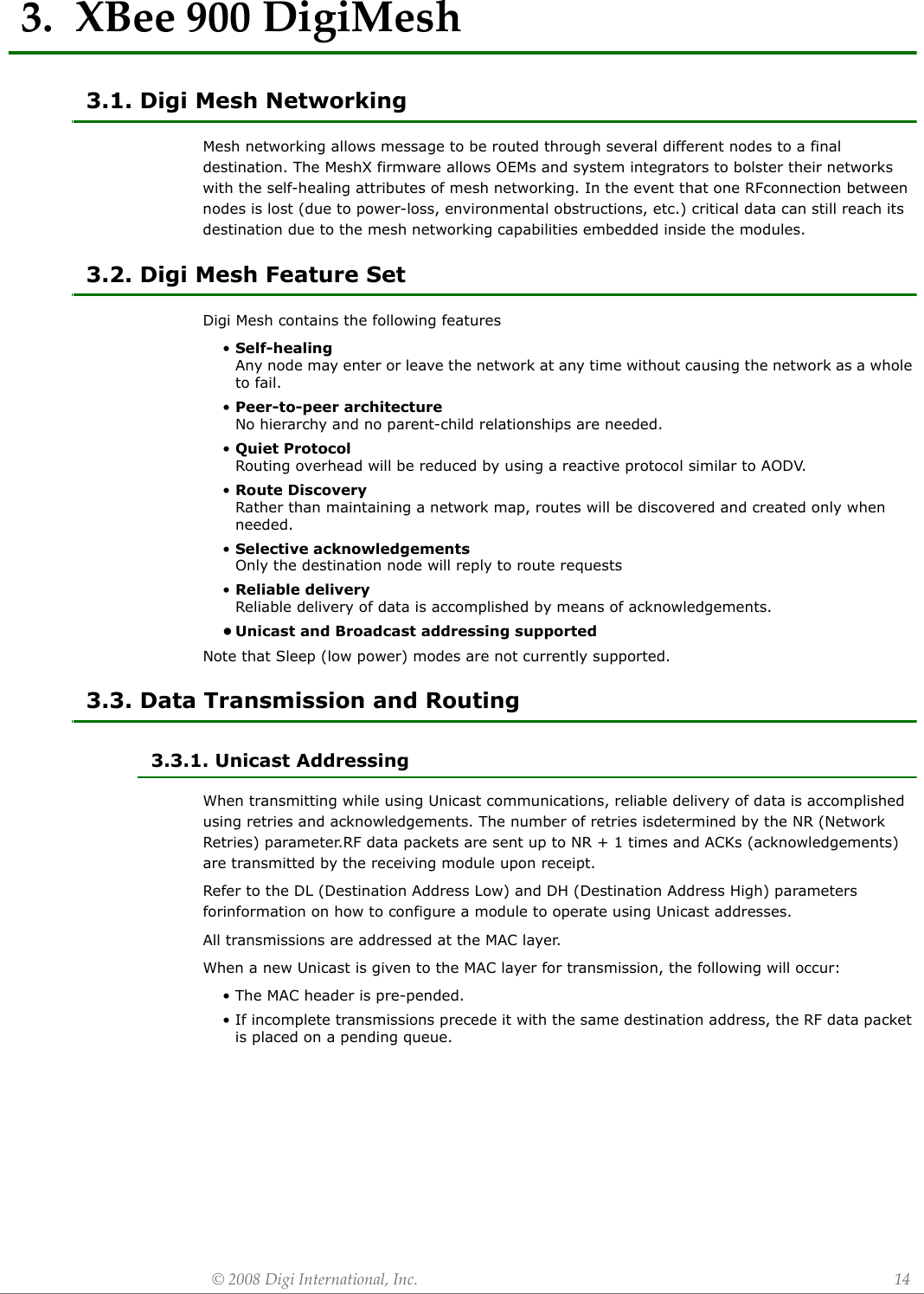
![XBee®/XBee‐PRO®900OEMRFModules©2008DigiInternational,Inc. 71.5. Pin SignalsFigure1‐03. XBee®/XBee‐PRO®900RFModulePinNumber(topsidesshown‐shieldsonbottom)Design Notes:• Minimum connections: VCC, GND, DOUT & DIN• Minimum connections to support serial firmware upgrades: VCC, GND, DIN, DOUT, RTS & DTR• Signal Direction is specified with respect to the module• Module includes a 30k Ohm resistor attached to RESET• Several of the input pull-ups can be configured using the PR command• Unused pins should be left disconnectedTable1‐02. PinAssignmentsfortheXBee®/XBee‐PRO®900Modules (Low‐assertedsignalsaredistinguishedwithahorizontallineabovesignalname.)Pin # Name Direction Description1 VCC - Power supply2 DOUT Output UART Data Out3 DIN / CONFIG Input UART Data In4 DIO12 Either Digital I/O 125RESET Input Module Reset (reset pulse must be at least 200 ns)6 PWM0 / RSSI / DIO10 Either PWM Output 0 / RX Signal Strength Indicator / Digital IO7 PWM / DIO11 Either Digital I/O 118 [reserved] - Do not connect9DTR / SLEEP_RQ/ DIO8 Either Pin Sleep Control Line or Digital IO 810 GND - Ground11 DIO4 Either Digital I/O 412 CTS / DIO7 Either Clear-to-Send Flow Control or Digital I/O 713 ON / SLEEP / DIO9 Output Module Status Indicator or Digital I/O 914 [reserved] - Do not connect15 Associate / DIO5 Either Associated Indicator, Digital I/O 516 RTS / DIO6 Either Request-to-Send Flow Control, Digital I/O 17 AD3 / DIO3 Either Analog Input 3 or Digital I/O 318 AD2 / DIO2 Either Analog Input 2 or Digital I/O 219 AD1 / DIO1 Either Analog Input 1 or Digital I/O 120 AD0 / DIO0 / ID Button Either Analog Input 0, Digital I/O 0, or Node Identification](https://usermanual.wiki/Digi/XBEE09P/User-Guide-924944-Page-7.png)
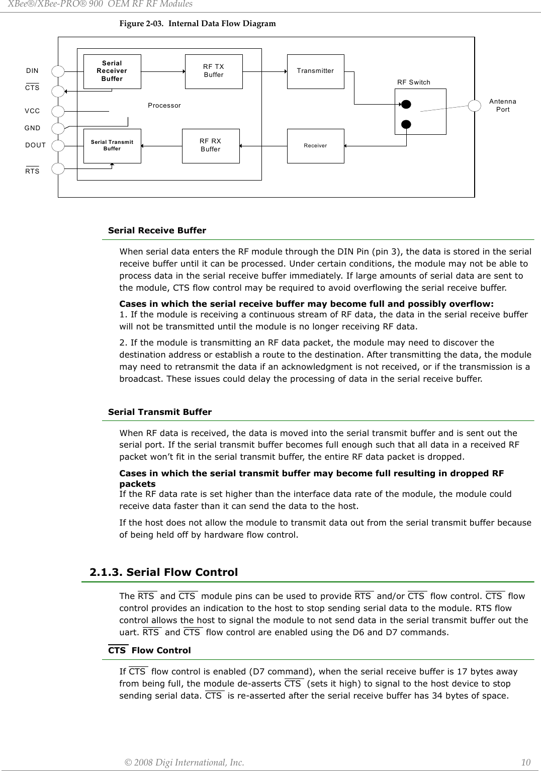
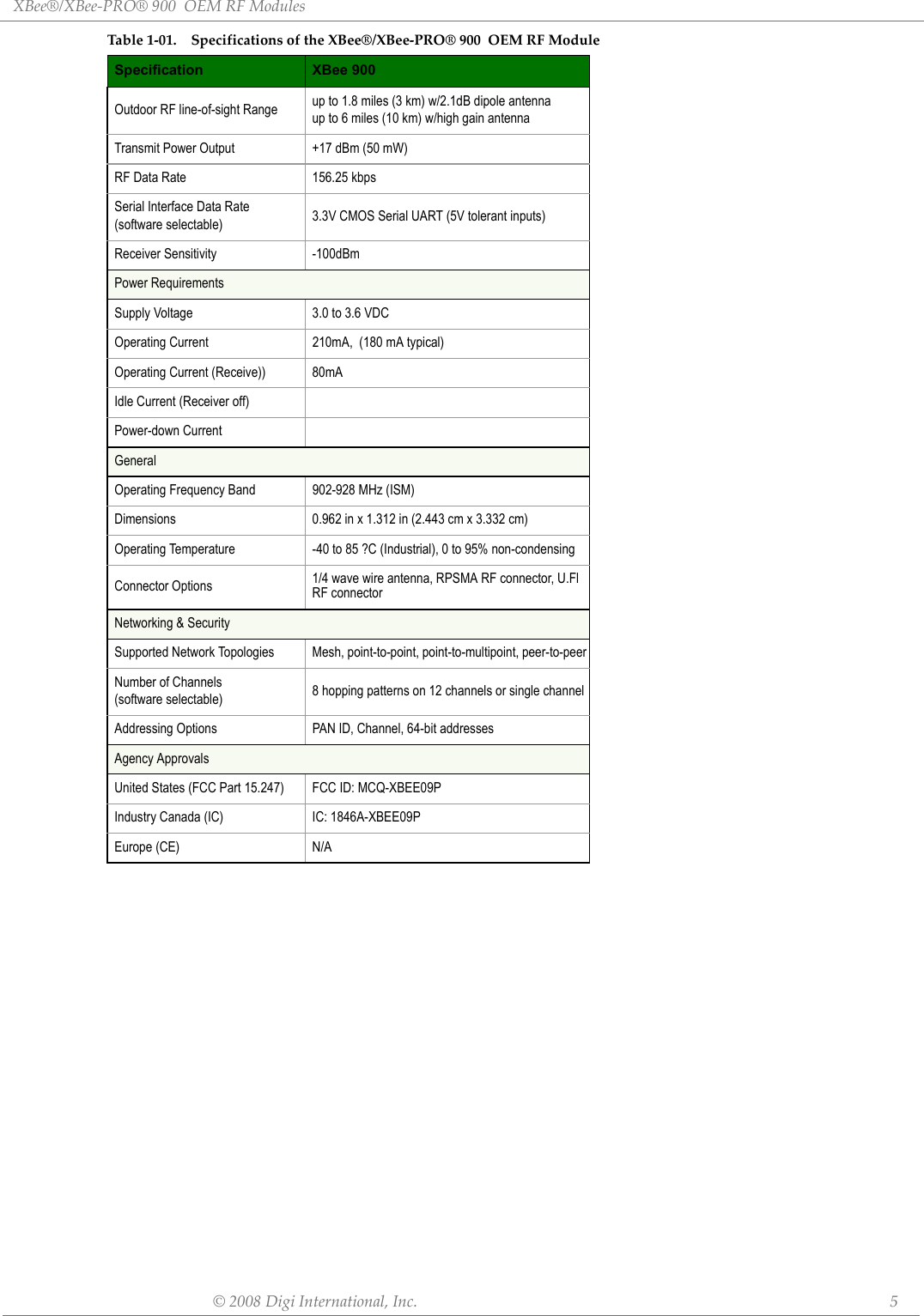
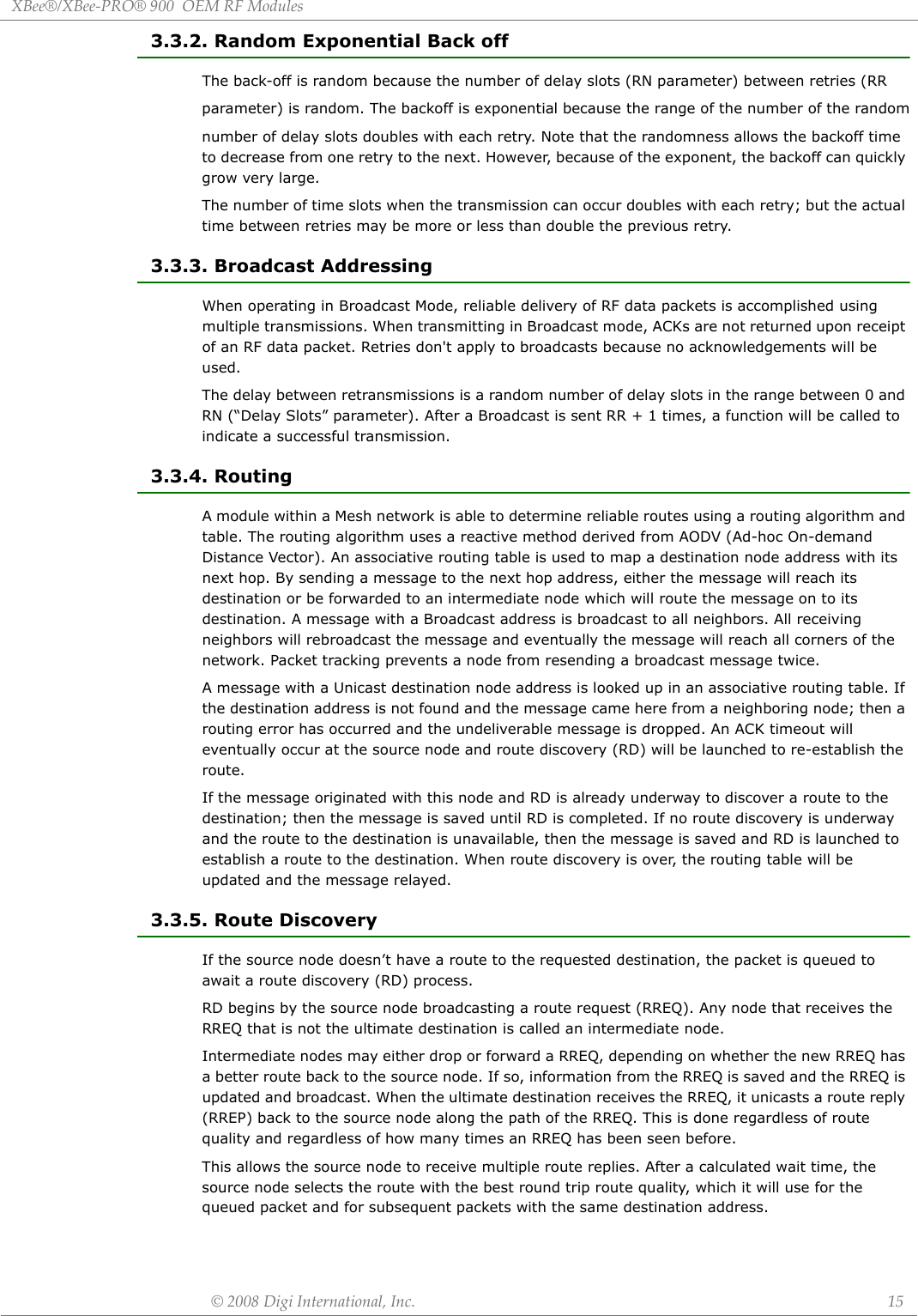
![XBee®/XBee‐PRO®900OEMRFRFModules©2008DigiInternational,Inc. 132.2.4. Command ModeTo modify or read RF Module parameters, the module must first enter into Command Mode - a state in which incoming serial characters are interpreted as commands. Refer to the API Mode section for an alternate means of configuring modules.AT Command ModeTo Enter AT Command Mode:Send the 3-character command sequence “+++” and observe guard times before and after the command characters. [Refer to the “Default AT Command Mode Sequence” below.]Default AT Command Mode Sequence (for transition to Command Mode):• No characters sent for one second [GT (Guard Times) parameter = 0x3E8]• Input three plus characters (“+++”) within one second [CC (Command Sequence Character) parameter = 0x2B.]• No characters sent for one second [GT (Guard Times) parameter = 0x3E8]All of the parameter values in the sequence can be modified to reflect user preferences.NOTE: Failure to enter AT Command Mode is most commonly due to baud rate mismatch. Ensure the ‘Baud’ setting on the “PC Settings” tab matches the interface data rate of the RF module. By default, the BD parameter = 3 (9600 bps).To Send AT Commands:Send AT commands and parameters using the syntax shown below.Figure2‐05.SyntaxforsendingATCommandsTo read a parameter value stored in the RF module’s register, omit the parameter field.The preceding example would change the RF module Destination Address (Low) to “0x1F”. To store the new value to non-volatile (long term) memory, subsequently send the WR (Write) command.For modified parameter values to persist in the module’s registry after a reset, changes must be saved to non-volatile memory using the WR (Write) Command. Otherwise, parameters are restored to previously saved values after the module is reset.System Response. When a command is sent to the module, the module will parse and execute the command. Upon successful execution of a command, the module returns an “OK” message. If execution of a command results in an error, the module returns an “ERROR” message.To Exit AT Command Mode:1. Send the ATCN (Exit Command Mode) command (followed by a carriage return). [OR]2. If no valid AT Commands are received within the time specified by CT (Command Mode Timeout) Command, the RF module automatically returns to Idle Mode. For an example of programming the RF module using AT Commands and descriptions of each config-urable parameter, refer to the "Examples" and "Command Reference Tables" chapters.](https://usermanual.wiki/Digi/XBEE09P/User-Guide-924944-Page-13.png)

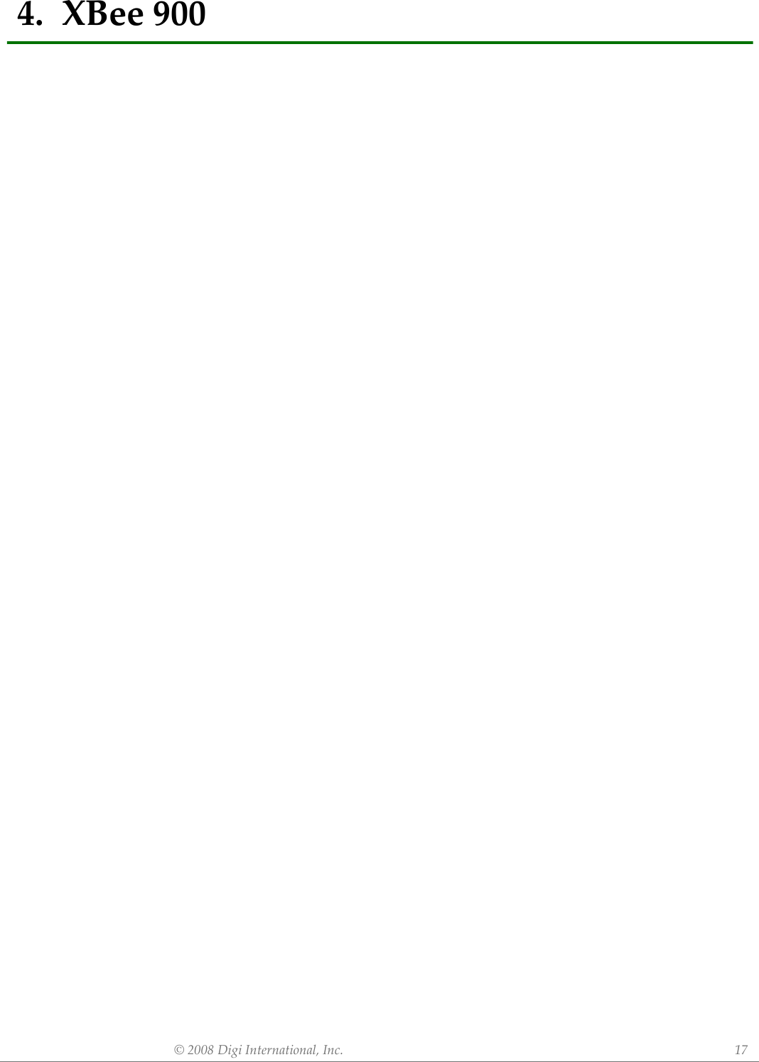
![XBee®/XBee‐PRO®900OEMRFModules©2008DigiInternational,Inc. 19Serial Interfacing (I/O)Table5‐03. SerialInterfacingCommandsAT Command Name and Description Parameter Range DefaultAPAPI mode. Set or read the API mode of the radio. The following settings are allowed: 0 API mode is off. All UART input and output is raw data and packets are delineated using the RO and RB parameters. 1 API mode is on. All UART input and output data is packetized in the API format, without escape sequences. 2 API mode is on with escaped sequences inserted to allow for control characters (XON, XOFF, escape, and the 0x7e delimiter to be passed as data. 0, 1, or 2 0AOAPI Output Format. Enables different API output frames. Options include: 0 ZigBee Standard Data Frames (0x90 for RF rx) 1 ZigBee Explicit Addressing Data Frames (0x91 for RF rx) 0, 1 0BDBaud rate. Set or read serial interface rate (speed for data transfer between radio modem and host). Values from 0-8 select preset standard rates. Values at 0x39 and above select the actual baud rate. Providing the host supports it. Baud rates can go as high as 1.875Mbps. The values from 0 to 8 are interpreted as follows: 0 - 1,200bps 3 - 9,600bps 6 - 57,600bps 1 - 2,400bps 4 - 19,200bps 7 - 115,200bps 2 - 4,800bps 5 - 38,400bps 8 - 230,400bps0 to 8, and 0x39 to 0x1c9c38 0x03 (9600 bps) ROPacketization Timeout. Set/Read number of character times of inter-character silence required before packetization. Set (RO=0) to transmit characters as they arrive instead of buffering them into one RF packet.0 - 0xFF [x character times] 3FTFlow Control Threshhold. Set or read flow control threshhold. De-assert CTS and/or send XOFF when FT bytes are in the UART receive buffer. Re-assert CTS when less than FT - 16 bytes are in the UART receive buffer. 17 to 382 0x016D = 365 GT Command Guard Time. Set required period of silence before and after the Command Mode Characters of the Command Mode Sequence (GT + CC + GT). The period of silence is used to prevent inadvertent entrance into AT Command Mode. If the GT time is less than RO time at the baud rate, then RO time will be used for GT time. 0 to 0xFFFF 0x3E8 ME Mesh Enable. Enable Digi Mesh network layer. Otherwise the application bypasses the Mesh layer and goes directly to the mac layer. All radios that wish to communicate must have the same setting. 0 to 1 0NBParity. Set or read parity settings for UART communications. The values from 0 to 4 are interpreted as follows: 0 No parity 3 Forced high parity 1 Even parity 4 Forced low parity 2 Odd parity0 to 4 0 (No parity) SBStop Bits. Set or read number of stop bits used for UART communications. The values from 0 to 4 are interpreted as follows: 0 - 1 stop bit 1 - 2 stop bits0 to 1 0 (1 stop bit) D7DIO7 Configuration. Configure options for the DIO7 line of the module. Options include: 0 = Input, unmonitored 1 = CTS flow control 3 = Digital input, monitored 4 = Digital output low 5 = Digital output high 6 = RS-485 Tx enable, low TX (0V on transmit, high when idle) 7 = RS-485 Tx enable, high TX (high on transmit, 0V when idle)0-1, 3-7 0D6DIO6 Configuration. Configure options for the DIO6 line of the module. Options include: 0 = Input, unmonitored 1 = RTS flow control 3 = Digital input, monitored 4 = Digital output low 5 = Digital output high 0-1, 3-5 0D5AD5/DIO5 Configuration. Configure options for the AD5/DIO5 line of the module. Options include: 0 = Input, unmonitored 1 = Power LED output 3 = Digital input, monitored 4 = Digital output low 5 = Digital output high 0-1, 3-5 1](https://usermanual.wiki/Digi/XBEE09P/User-Guide-924944-Page-19.png)
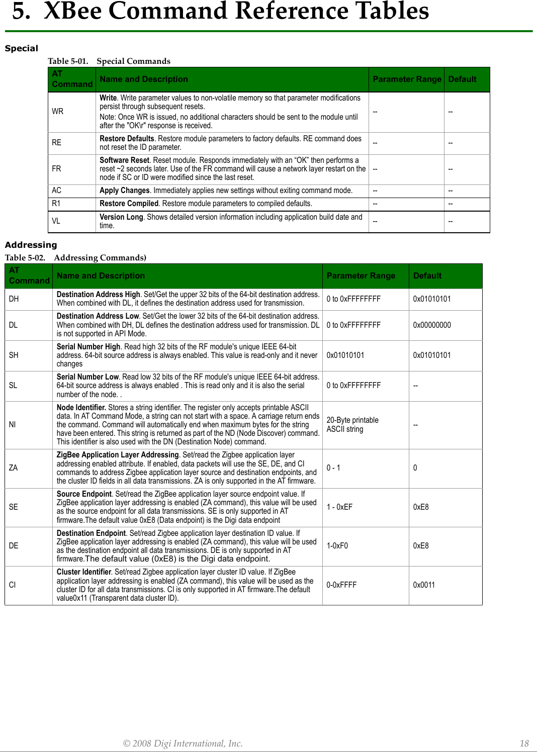
![XBee®/XBee‐PRO®900OEMRFModules©2008DigiInternational,Inc. 20I/O CommandsTable5‐04. I/OCommandsAT Command Name and Description Parameter Range DefaultP0DIO10/PWM0 Configuration. Configure options for the DIO10/PWM0 line of the module. Options include: 0 = Input, unmonitored 1 = RSSI 2 = PWM0 3 = Digital input, monitored 4 = Digital output low 5 = Digital output high 0-5 1P1DIO11/PWM1 Configuration. Configure options for the DIO11/PWM1 line of the module. Options include: 0 = Input, unmonitored 2 = PWM1 3 = Digital input, monitored 4 = Digital output low 5 = Digital output high 0, 2-5 0P2DIO12 Configuration. Configure options for the DIO12 line of the module. Options include: 0 = Input, unmonitored 3 = Digital input, monitored 4 = Digital output low 5 = Digital output high 0, 3-5 0???RP RSSI PWM Timer. Time RSSI signal will be output after last transmission. When RP = 0xFF, output will always be on. 0 - 0xFF [x 100 ms] 0x28 (40d)D0AD0/DIO0 Configuration. Configure options for the AD0/DIO0 line of the module. Options include: 0 = Input, unmonitored 3 = Digital input, monitored 4 = Digital output low 5 = Digital output high 0, 3-5 0D1AD1/DIO1 Configuration. Configure options for the AD1/DIO1 line of the module. Options include: 0 = Input, unmonitored 3 = Digital input, monitored 4 = Digital output low 5 = Digital output high 0, 3-5 0D2AD2/DIO2 Configuration. Configure options for the AD2/DIO2 line of the module. Options include: 0 = Input, unmonitored 3 = Digital input, monitored 4 = Digital output low 5 = Digital output high 0, 3-5 0D3AD3/DIO3 Configuration. Configure options for the AD3/DIO3 line of the module. Options include: 0 = Input, unmonitored 3 = Digital input, monitored 4 = Digital output low 5 = Digital output high 0, 3-5 0D4AD4/DIO4 Configuration. Configure options for the AD4/DIO4 line of the module. Options include: 0 = Input, unmonitored 3 = Digital input, monitored 4 = Digital output low 5 = Digital output high 0, 3-5 0](https://usermanual.wiki/Digi/XBEE09P/User-Guide-924944-Page-20.png)
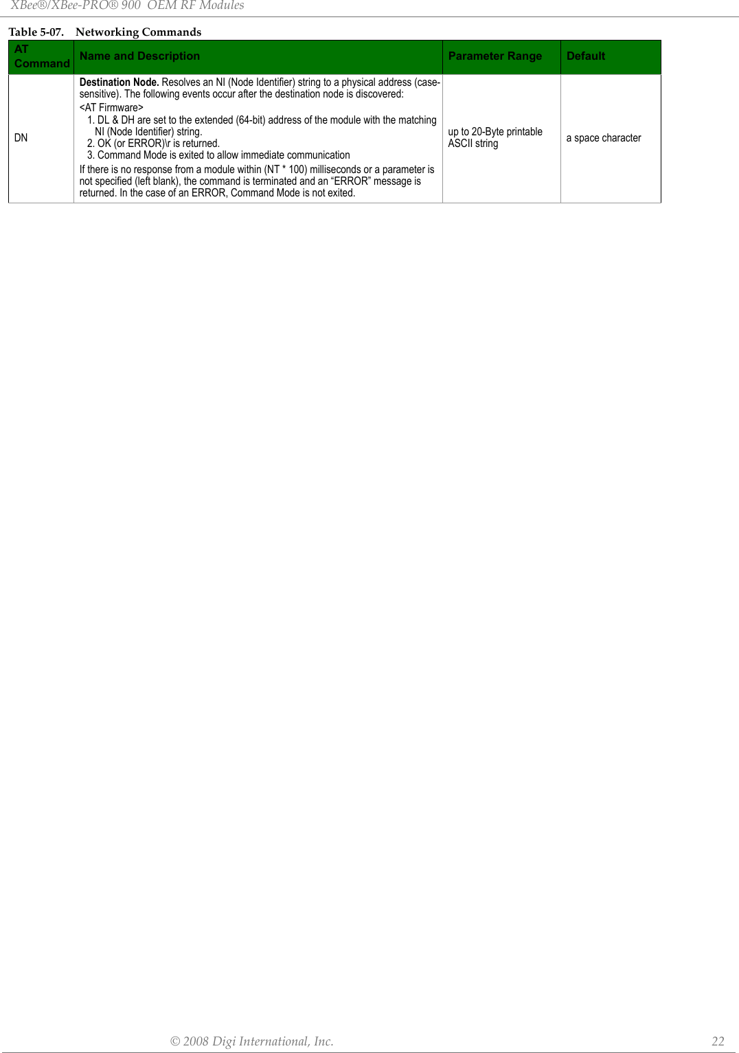
![XBee®/XBee‐PRO®900OEMRFModules©2008DigiInternational,Inc. 21DiagnosticsAT Command OptionsDigi Mesh: Networking & SecurityPRSet/read the bit field that configures the internal pull-up resistor status for the I/O lines. "1" specifies the pull-up resistor is enabled. "0" specifies no pullup.Bits:"0 - DIO4 (Pin 11)1 - AD3 / DIO3 (Pin 17)2 - AD2 / DIO2 (Pin 18)3 - AD1 / DIO1 (Pin 19)4 - AD0 / DIO0 (Pin 20)5 - RTS / DIO6 (Pin 16)6 - DTR / Sleep Request / DIO8 (Pin 9)7 - DIN / Config (Pin 3)8 - Associate / DIO5 (Pin 15)9 - On/Sleep / DIO9 (Pin 13)10 - DIO12 (Pin 4)11 - PWM0 / RSSI / DIO10 (Pin 6)12 - PWM1 / DIO11 (Pin 7)0 - 0x1FFF 0 - 0x1FFFTable5‐05. DiagnosticsCommandsAT Command Name and Description Parameter Range DefaultVR Firmware Version. Read firmware version of the module. 0 - 0xFFFF [read-only] Factory-setHV Hardware Version. Read hardware version of the module. 0 - 0xFFFF [read-only] Factory-set%VSupply Voltage. Reads the voltage on the Vcc pin. To convert the reading to a mV reading, divide the read value by 1023 and multiply by 1200. A %V reading of 0x8FE (2302 decimal) represents 2700mV or 2.70V.--Table5‐06. ATCommandOptionsCommandsAT Command Name and Description Parameter Range DefaultCTCommand Mode Timeout. Set/Read the period of inactivity (no valid commands received) after which the RF module automatically exits AT Command Mode and returns to Idle Mode.2 - 0x028F [x 100 ms] 0x64 (100d)CN Exit Command Mode. Explicitly exit the module from AT Command Mode. -- --GTGuard Times. Set required period of silence before and after the Command Sequence Characters of the AT Command Mode Sequence (GT + CC + GT). The period of silence is used to prevent inadvertent entrance into AT Command Mode.1 - 0x0CE4 [x 1 ms] (max of 3.3 decimal sec)0x3E8 (1000d)CCCommand Character. Set or read the character to be used between guard times of the AT Command Mode Sequence. The AT Command Mode Sequence causes the radio modem to enter Command Mode (from Idle Mode).0 - 0xFF 0x2BTable5‐07. NetworkingCommandsAT Command Name and Description Parameter Range DefaultIDNetwork Identifier. Set or read the user network address. Nodes must have the same network address to communicate. Changes to ID should be written to non-volatile memory using the WR command. 0x0000 to 0x7FFF 0x7FFF NT Node Discover Timeout. Set/Read the amount of time a node will spend discovering other nodes when ND or DN is issued.0 - 0xFC [x 100 msec] 0x3C (60d)NDNode Identifier. Stores a string identifier. The string accepts only printable ASCII data In AT Command Mode, the string can not start with a space. A Carriage return ends the command. Command will automatically end when maximum bytes for the string have been entered. This string is returned as part of the ATND (Network Discover) command. This identifier is also used with the ATDN (Destination Node) command. . 20 byte ASCII string a space characterTable5‐04. I/OCommandsAT Command Name and Description Parameter Range Default](https://usermanual.wiki/Digi/XBEE09P/User-Guide-924944-Page-21.png)
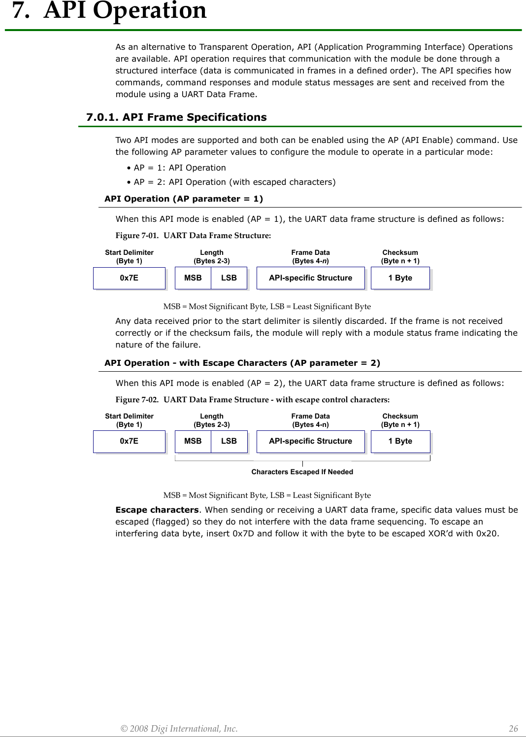
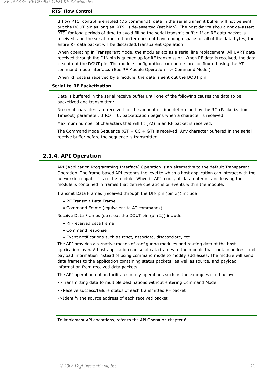
![XBee®/XBee‐PRO®900OEMRFModules]©2008DigiInternational,Inc. 27Data bytes that need to be escaped:• 0x7E – Frame Delimiter•0x7D – Escape• 0x11 – XON• 0x13 – XOFFNote: In the above example, the length of the raw data (excluding the checksum) is 0x0002 and the checksum of the non-escaped data (excluding frame delimiter and length) is calculated as: 0xFF - (0x23 + 0x11) = (0xFF - 0x34) = 0xCB.ChecksumTo test data integrity, a checksum is calculated and verified on non-escaped data.To calculate: Not including frame delimiters and length, add all bytes keeping only the lowest 8 bits of the result and subtract the result from 0xFF.To verify: Add all bytes (include checksum, but not the delimiter and length). If the checksum is correct, the sum will equal 0xFF.7.0.2. API FramesFrame data of the UART data frame forms an API-specific structure as follows:Figure7‐03. UARTDataFrame&API‐specificStructure:The cmdID frame (API-identifier) indicates which API messages will be contained in the cmdData frame (Identifier-specific data). Note that multi-byte values are sent big endian. The modules support the following API frames:Example - Raw UART Data Frame (before escaping interfering bytes): 0x7E 0x00 0x02 0x23 0x11 0xCB0x11 needs to be escaped which results in the following frame: 0x7E 0x00 0x02 0x23 0x7D 0x31 0xCBTable7‐08. APIFrameNamesandValu e s API Frame Names ValuesModem Status 0x8AAdvanced Modem Status 0x8CAT Command 0x08AT Command - Queue Parameter Value 0x09AT Command Response 0x88Remote Command Request 0x17Remote Command Response 0x97TransmitRequest 0x10Explicit AddressingCommandFrame0x11TransmitStatus 0x8B ReceivePacket (AO=0) 0x90Length(Bytes 2-3)Checksum(Byte n + 1)MSB LSB 1 ByteStart Delimiter (Byte 1)0x7EFrame Data(Bytes 4-n) API-specific StructureIdentifier-specific DatacmdDataAPI IdentifiercmdID](https://usermanual.wiki/Digi/XBEE09P/User-Guide-924944-Page-27.png)
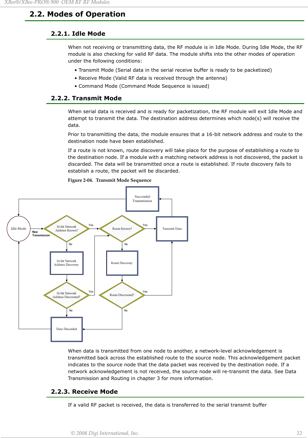
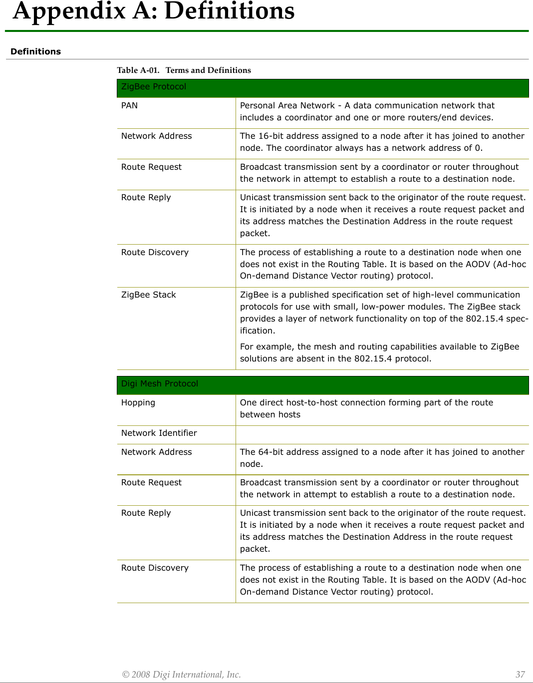
![XBee®/XBee‐PRO®900OEMRFModules]©2008DigiInternational,Inc. 28Modem StatusAPI Identifier Value: (0x8A) RF module status messages are sent from the module in response to specific conditions.Figure7‐04. ModemStatusFramesExplicit RxIndicator (AO=1) 0x91XBee Sensor ReadIndicator (AO=0) 0x94Node Identification Indicator (AO=0) 0x95Table7‐08. APIFrameNamesandValu e s API Frame Names ValuescmdData0x8ALength ChecksumStart Delim iter Fram e D ataIdentifier-specific DataAPI IdentifierMSB LSB0x7E 1 ByteAPI-specific StructureStatus (Byte 5)0 = Hardware reset1 = Watchdog timer reset2 = Associated3 = Disassociated4 = Synchronization Lost (Beacon-enabled only)5 = Coordinator realignment6 = Coordinator started](https://usermanual.wiki/Digi/XBEE09P/User-Guide-924944-Page-28.png)
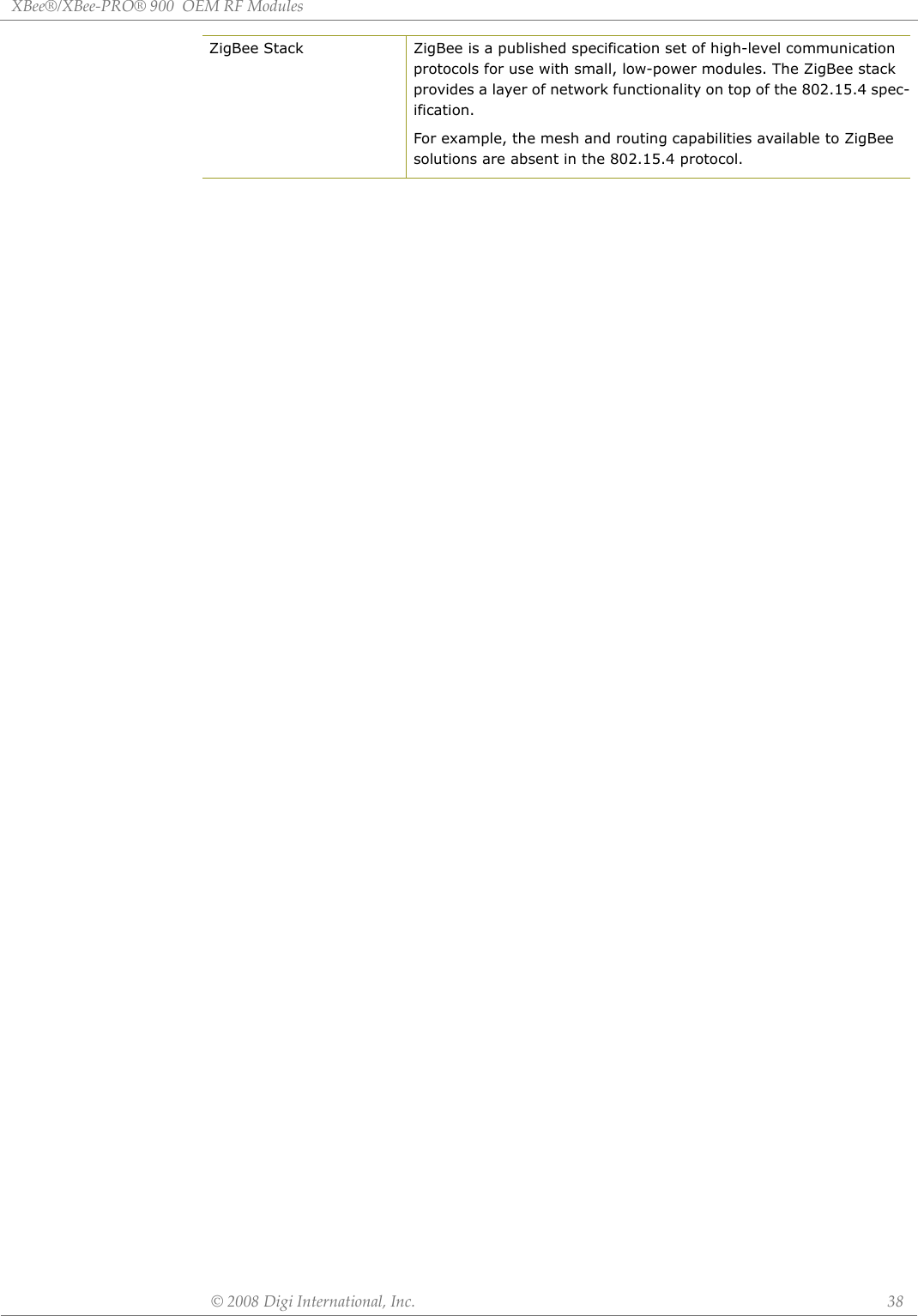
![XBee®/XBee‐PRO®900OEMRFModules]©2008DigiInternational,Inc. 29AT CommandAPI Identifier Value: (0x08) Allows for module parameter registers to be queried or set.Figure7‐5. ATCommandFramesFigure7‐6. Example:APIframeswhenreadingtheNJparametervalueofthemodule.Figure7‐7. Example:APIframeswhenmodifyingtheNJparametervalueofthemodule.A string parameter used with the NI (Node Identifier), ND (Node Discover) and DH (Destination Address High) command is terminated with a 0x00 character.AT Command - Queue Parameter ValueAPI Identifier Value: (0x09) This API type allows module parameters to be queried or set. In contrast to the “AT Command” API type, new parameter values are queued and not applied until either the “AT Command” (0x08) API type or the AC (Apply Changes) command is issued. Register queries (reading parameter values) are returned immediately.Figure7‐8. ATCommandFrames (Notethatframesareidenticaltothe“ATCommand”APItypeexceptfortheAPIidentifier.)cmdData0x08Length ChecksumStart Delimiter Frame DataIdentifier-specific DataAPI IdentifierMSB LSB0x7E 1 ByteAPI-specific StructureFrame ID (Byte 5)Identifies the UART data frame for the host to correlate with a subsequent ACK (acknowledgement).If set to ‘0’, no response is sent.AT Command (Bytes 6-7)Command Name - Two ASCII characters that identify the AT Command.Parameter Value (Byte(s) 8-n)If present, indicates the requested parameter value to set the given register.If no characters present, register is queried.*Length[Bytes]=APIIdentifier+FrameID+ATCommand**“R”valuewasarbitrarilyselected.Checksum0x0DByte 8AT CommandBytes 6-7Frame ID**0x52 (R)Byte 50x4E (N) 0x4A (J)API Identifier0x08Byte 4Start DelimiterByte 10x7ELength*Bytes 2-30x00 0x04*Length[Bytes]=APIIdentifier+FrameID+ATCommand+ParameterValue**“M”valuewasarbitrarilyselected.Checksum0xD2Byte 9AT CommandBytes 6-70x4E (N) 0x4A (J)Parameter Value0x40Bytes 8Frame ID**0x4D (M)Byte 5Length*Bytes 2-30x00 0x05API Identifier0x08Byte 4Start DelimiterByte 10x7EcmdData0x09Length ChecksumStart Delimiter Frame DataIdentifier-specific DataAPI IdentifierMSB LSB0x7E 1 ByteAPI-specific StructureFrame ID (Byte 5)Identifies the UART data frame for the host to correlate with a subsequent ACK (acknowledgement).If set to ‘0’, no response is sent.AT Command (Bytes 6-7)Command Name - Two ASCII characters that identify the AT Command.Parameter Value (Byte(s) 8-n)If present, indicates the requested parameter value to set the given register.If no characters present, register is queried.](https://usermanual.wiki/Digi/XBEE09P/User-Guide-924944-Page-29.png)
![XBee®/XBee‐PRO®900OEMRFModules]©2008DigiInternational,Inc. 30AT Command ResponseAPI Identifier Value: (0x88) Response to previous command.In response to an AT Command message, the module will send an AT Command Response message. Some commands will send back multiple frames (for example, the ND (Node Discover) command). Figure7‐9. ATCommandResponseFrames.Remote AT Command RequestAPI Identifier Value: (0x17) Allows for module parameter registers on a remote device to be queried or setFigure7‐10. RemoteATCommandRequestcmdData0x88Length ChecksumStart Delimiter Frame DataIdentifier-specific DataAPI IdentifierMSB LSB0x7E 1 ByteAPI-specific StructureFrame ID (Byte 5 )Identifies the UART data frame being reported.Note: If Frame ID = 0 in AT Command Mode, no AT Command Response will be given.AT Command (Bytes 6-7)Command Name - Two ASCII characters that identify the AT Command.Status (Byte 8)0 = OK1 = ERROR2 = Invalid Command3 = Invalid ParameterThe HEX (non-ASCII) value of the requested registerValue (Byte(s) 9-n)16-bit Destination Network Address (bytes 14-15)Frame ID (Byte 5)Identifies the UART data frame being reported. If Frame ID = 0, no AT command response will be givencmdDataLength ChecksumStart Delimiter Frame DataIdentifier-specific DataAPI IdentifierMSB LSB0x7E 1 ByteAPI-specific Structure64-bit Destination Address (bytes 6-13)Set to match the 64-bit address of the destination, MSB first, LSB last. Broadcast = 0x000000000000FFFF.Command Options (byte 16)0x02 - Apply changes on remote. (If not set, AC command must be sent before changes will take effect.)All other bits must be set to 0.0x017Command Data (byte 19-n)If present, indicates the requested parameter value to set the given register. If no characters present, the register is queried.Set to match the 16-bit network address of the destination, MSB first, LSB last. Set to 0xFFFE for broadcast TX, or if the network address is unknown.Command Name (bytes 17-18)Name of the command](https://usermanual.wiki/Digi/XBEE09P/User-Guide-924944-Page-30.png)
![XBee®/XBee‐PRO®900OEMRFModules]©2008DigiInternational,Inc. 31Remote Command ResponseAPI Identifier Value: (0x97)If a module receives a remote command response RF data frame in response to a Remote AT Command Request, the module will send a Remote AT Command Response message out the UART. Some commands may send back multiple frames--for example, Node Discover (ND) command. Figure7‐11. RemoteATCommandResponse.Transmit RequestAPI Identifier Value: (0x10) A TX Request message will cause the module to send RF Data as an RF Packet.TX Packet FramescmdData0x97Length ChecksumStart Delimiter Frame DataIdentifier-specific DataAPI IdentifierMSB LSB0x7E 1 ByteAPI-specific Structure16-bit Responder Network Address (bytes 14-15)Set to the 16-bit network address of the remote. Set to 0xFFFE if unknown.Frame ID (Byte 5)Status (byte 18)0 = OK1 = Error2 = Invalid Command3 = Invalid Parameter64-bit Responder Address (bytes 6-13)Indicates the 64-bit address of the remote module that is responding to the Remote AT Command requestIdentifies the UART data frame being reported. Matches the Frame ID of the Remote Command Request the remote is responding to.Command Name (bytes 16-17)Name of the command. Two ASCII characters that identify the AT commandCommand Data (byte 19-n)The value of the requested register.](https://usermanual.wiki/Digi/XBEE09P/User-Guide-924944-Page-31.png)
![XBee®/XBee‐PRO®900OEMRFModules]©2008DigiInternational,Inc. 32Figure7‐12. TransmitRequest.RF Data: Bytes (s) 18-nUp to 72 Bytesper packet0x08 - Send multicast transmission. (Unicast sent if not set.)All other bits must be set to 0.Options (byte 17)MSB first, LSB last.Set to 0xFFFE forBroadcast TX or if NetworkAddress is not known16-bit Destination Network Address (bytes 14-15)0x7E API-specific Structure 1 ByteMSB LSBStart delimiter Length Frame Data Checksum0x10API IdentifiercmdDataIdentifier specific dataFrame ID (byte 5)Identifies the UART data frame for the host tocorrelate with a subsequent ACK (acknowledgement).Setting Frame ID to ‘0' will disable response frame.64-bit Address (bytes 6-13)MSB first, LSB last.Broadcast =0x000000000000FFFFSets maximum number of hops a broadcasttransmission can traverse. If set to 0, the TX radius willbe set to the network maximum hops value (10).Broadcast Radius (byte 16)](https://usermanual.wiki/Digi/XBEE09P/User-Guide-924944-Page-32.png)
![XBee®/XBee‐PRO®900OEMRFModules]©2008DigiInternational,Inc. 33Explicit Addressing ZigBee Command Frame API Identifier Value: (0x11)Allows ZigBee application layer fields (endpoint and cluster ID) to be specified for a data transmission. Figure7‐13. ExplicitAddressingZigBeeCommandFrame.Identifies the UART data frame for the host correlate with a subsequent ACK (acknowledgement). Setting Frame ID to ‘ 0’ will disable response frame.Frame ID (byte 5)64-bit Destination Address (bytes 6-13)Destination 64-bit (extended) address. Set to 0xFFFF for broadcast. 16-bit Destination Network Address (byted 14-15)Destination network address (if known). Set to 0xFFFE for broadcast transmissions or if the destination network address is not known.Source endpoint (byte 16)Source endpoint for the transmission .Reserved (byte 18)Set to 0Cluster ID (byte 19)Cluster ID used in the transmissionProfile ID (bytes 20-21)Multiple profile IDs not supported. Set to 0xC105.Broadcast Radius (byte 22)Sets the maximum number of hops a broadcast transmission can traverse. If set to 0, the transmission radius will be set to the network maximum hops value.Options (byte 23)0x08 - Send multicast transmission (unicast sent if not set ). All other bits must be set to 0.0x7E API-specific Structure 1 ByteMSB LSBStart delimiter Length Frame Data Checksum0x11 cmdDataAPI Identifier Identifier specific data123467891011Destination endpoint (byte 17)Destination endpoint for the transmission.5RF Data (byte 24-n) Up to 72 bytes](https://usermanual.wiki/Digi/XBEE09P/User-Guide-924944-Page-33.png)
![XBee®/XBee‐PRO®900OEMRFModules]©2008DigiInternational,Inc. 34Transmit StatusAPI Identifier Value: 0x8B When a TX Request is completed, the module sends a TX Status message. This message will indicate if the packet was transmitted successfully or if there was a failure.Figure7‐14. TXStatusFramesReceive PacketAPI Identifier Value: (0x90) When the module receives an RF packet, it is sent out the UART using this message type.Figure7‐15. RXPacketFramescmdData0x8BLength ChecksumStart Delimiter Frame DataIdentifier-specific DataAPI IdentifierMSB LSB0x7E 1 ByteAPI-specific StructureRemote Network Address (Bytes 6-7)16-bit Network Address the packet was delivered to (if success). If not success, this address matches the Destination Network Address that was provided in the Transmit Request Frame.Transmit Retry Count (Byte 8)The number of application transmission retries that took place.Discovery Status (Byte 10)0x00 = No Discovery Overhead0x01 = Address Discovery0x02 = Route Discovery0x03 = Address and Route DiscoveryDelivery Status (Byte 9)0x00 = Success0x02 = CCA Failure0x15 = Invalid destination endpoint0x21 = Network ACK Failure0x22 = Not Joined to Network0x23 = Self-addressed0x24 = Address Not Found0x25 = Route Not FoundFrame ID (Byte 5)Identifies UART data frame being reported.cmdData0x90Length ChecksumStart Delimiter Frame DataIdentifier-specific DataAPI IdentifierMSB LSB0x7E 1 ByteAPI-specific Structure0x01 - Packet Acknowledged0x02 - Packet was a broadcast packet Up to 72 Bytes per packet64-bit Address (Bytes 5-12)Options (Byte 15)RF Data (Byte(s) 16-n)16-bit Network Address(Bytes 13-14)MSB (most significant byte) first, LSB (least significant) lastMSB (most significant byte) first, LSB (least significant) last](https://usermanual.wiki/Digi/XBEE09P/User-Guide-924944-Page-34.png)
![XBee®/XBee‐PRO®900OEMRFModules]©2008DigiInternational,Inc. 35 Explicit Rx IndicatorAPI Identifier Value:(0x91) When the modem receives a RF packet it is sent out the UART using this message type (when AO=1).Figure7‐16. ZigBeeExplicitRxIndicators0x7E API-specific Structure 1 ByteMSB LSB0x91 cmdDataStart delimiter Length Frame Data ChecksumAP Identifier Identifier specific dataDestination 64-bit (extended) address. Set to 0xFFFF for broadcast.64-bit Source address (bytes 5-12)Destination network address (if known). Set to 0xFFFE for broadcast transmissions or if the destination network address is not known.16-bit Source network address (13-14)Endpoint of the source that initiated the transmission Source endpoint (byte 15)Endpoint of the destination the message is addressed to.Destination endpoint (byte 16)Cluster ID the packet was addressed to.Cluster ID (byte 17-18)Profile ID the packet was addressed to. (Multiple profile IDs not yet supported .)Profile ID (byte 19-20)0x01 – Packet Acknowledged0x02 – Packet was a broadcast packetOptions (byte 21)Up to 72 bytes.RF data (byte 22-n)51234678](https://usermanual.wiki/Digi/XBEE09P/User-Guide-924944-Page-35.png)
![XBee®/XBee‐PRO®900OEMRFModules]©2008DigiInternational,Inc. 36Node Identification IndicatorAPI Identifier Value: 0x95This frame is received on the coordinator when a module transmits a node identification message to identify itself to the coordinator (when AO=0). The data portion of this frame is similar to a Node Discovery response frame (see ND command).Figure7‐17. NodeIdentificationIndicator](https://usermanual.wiki/Digi/XBEE09P/User-Guide-924944-Page-36.png)
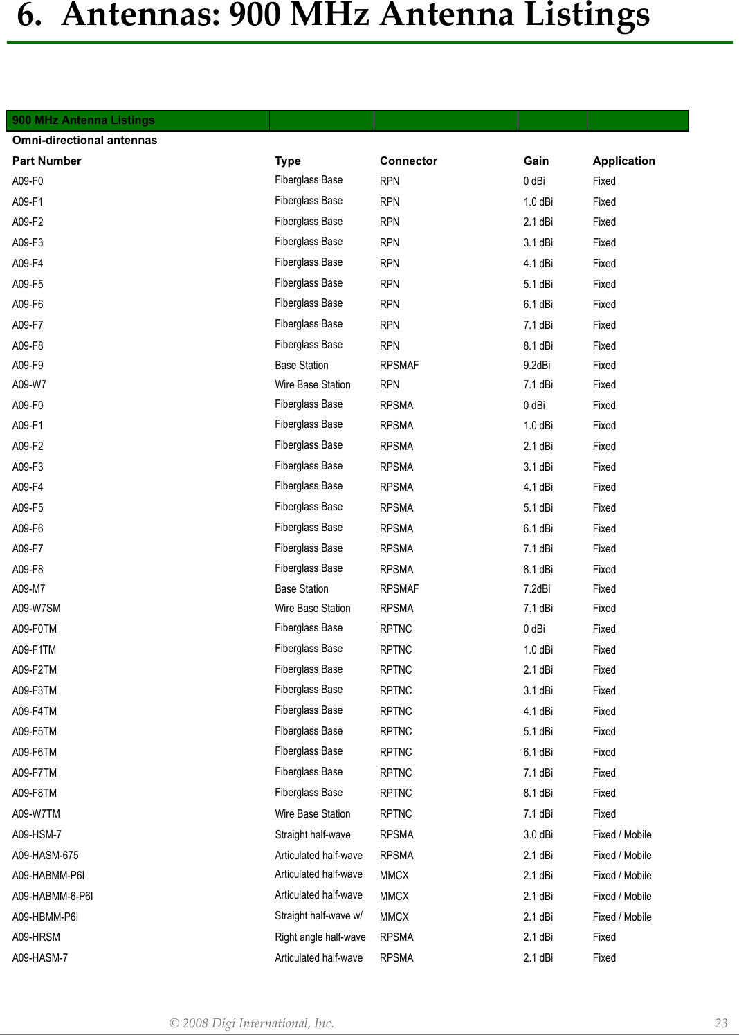
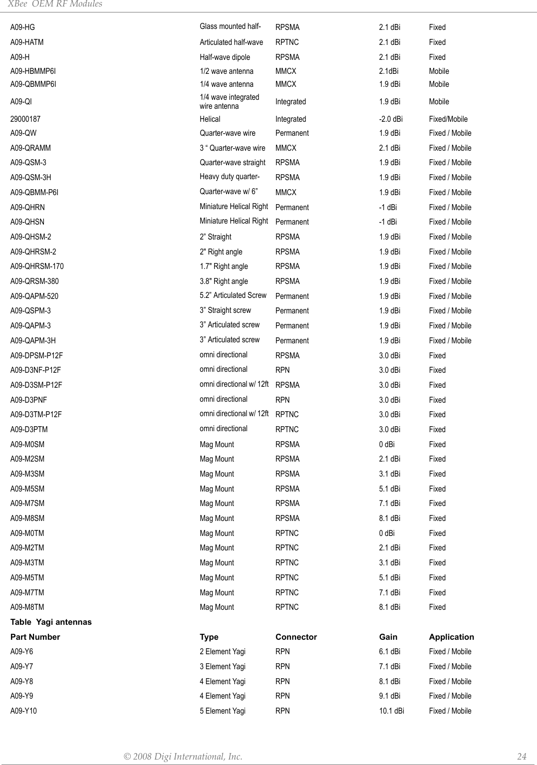
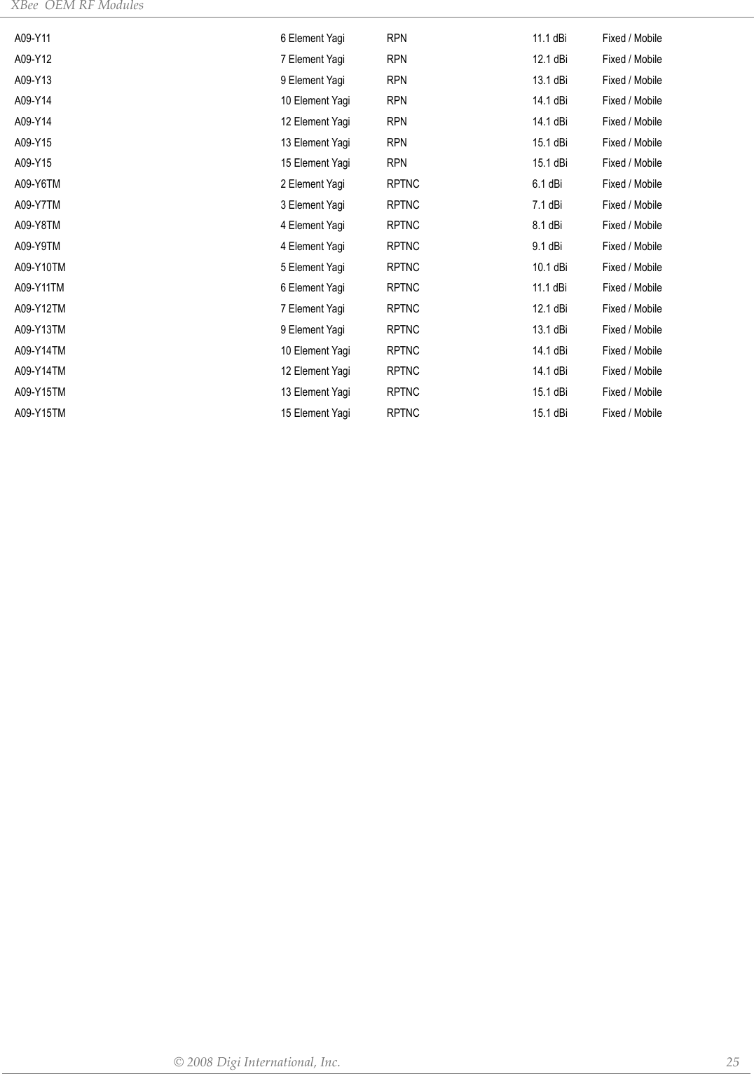
![©2008DigiInternational,Inc. 39AppendixB:AgencyCertificationsUnited States FCCThe XBee®/XBee-PRO® 900 RF Module complies with Part 15 of the FCC rules and regulations. Compliance with the labeling requirements, FCC notices and antenna usage guidelines is required.To fufill FCC Certification, the OEM must comply with the following regulations:OEM Labeling RequirementsWARNING: The Original Equipment Manufacturer (OEM) must ensure that FCC labeling requirements are met. This includes a clearly visible label on the outside of the final product enclosure that displays the contents shown in the figure below.Required FCC Label for OEM products containing the XBee®/XBee-PRO® 900 RF Module FCC NoticesIMPORTANT: The XBee®/XBee-PRO® 900 OEM RF Module has been certified by the FCC for use with other products without any further certification (as per FCC section 2.1091). Modifications not expressly approved by Digi could void the user's authority to operate the equipment.IMPORTANT: OEMs must test final product to comply with unintentional radiators (FCC section 15.107 & 15.109) before declaring compliance of their final product to Part 15 of the FCC Rules.IMPORTANT: The RF module has been certified for remote and base radio applications. If the module will be used for portable applications, the device must undergo SAR testing.This equipment has been tested and found to comply with the limits for a Class B digital device, pursuant to Part 15 of the FCC Rules. These limits are designed to provide reasonable protection against harmful interference in a residential installation. This equipment generates, uses and can radiate radio frequency energy and, if not installed and used in accordance with the instructions, may cause harmful interference to radio communications. However, there is no guarantee that interference will not occur in a particular installation. If this equipment does cause harmful interference to radio or television reception, which can be determined by turning the equipment off and on, the user is encouraged to try to correct the interference by one or more of the following measures: Re-orient or relocate the receiving antenna, Increase the separation between the equipment and receiver, Connect equipment and receiver to outlets on different circuits, or Consult the dealer or an experienced radio/TV technician for help.FCC-Approved Antennas (900 MHz)The XBee®/XBee-PRO® 900 RF Module can be installed utilizing antennas and cables constructed with standard connectors (Type-N, SMA, TNC, etc.) if the installation is performed professionally and according to FCC guidelines. For installations not performed by a professional, non-standard connectors (RPSMA, RPTNC, etc.) must be used.The modules are FCC approved for fixed base station and mobile applications on channels 0x0B-0x1A for XBee®/XBee-PRO® 900 and on channels 0x0B - 0x18 for Xbee Series2 Pro. If the antenna is mounted at least 20cm (8 in.) from nearby persons, the application is considered a 1. The system integrator must ensure that the text on the external label provided with this device is placed on the outside of the final product. [Figure A-01] 2. XBee®/XBee-PRO® 900 RF Module may only be used with antennas that have been tested and approved for use with this module [refer to the antenna tables in this section].Contains FCC ID:MCQ-XBEE09PThe enclosed device complies with Part 15 of the FCC Rules. Operation is subject to the following two conditions: (i.) this device may not cause harmful interference and (ii.) this device must accept any interference received, including interference that may cause undesired operation.](https://usermanual.wiki/Digi/XBEE09P/User-Guide-924944-Page-39.png)