Digi XBEE09P XBee-PRO 900 OEM RF Module User Manual XBEE
Digi International Inc XBee-PRO 900 OEM RF Module XBEE
Digi >
User Manual

Digi International Inc.
11001 Bren Road East
Minnetonka, MN 55343
877 912-3444 or 952 912-3444
http://www.digi.com
DRAFT
XBee®/XBee-PRO® 900 OEM RF Modules
XBee®/XBee-PRO® 900 OEM RF Mod-
ules
RF Module Operation
RF Module Configuration
Appendices
OEM RF Modules by Digi International
90000903-A
3/30/2008

XBee®/XBee‐PRO®900OEMRFModules
©2008DigiInternational,Inc. 2
© 2008 Digi International, Inc. All rights reserved
Nopartofthecontentsofthismanualmaybetransmittedorreproducedinany
formorbyanymeanswithoutthewrittenpermissionofDigiInternational,Inc.
ZigBee®isaregisteredtrademarkoftheZigBeeAlliance.
XBee®/XBee‐PRO®900isaregisteredtrademarkofDigiInternational,Inc.
TechnicalSupport:Phone:(801)765‐9885
LiveChat:www.digi.com
E‐support:http://www.digi.com/support/eservice/eservicelogin.jsp

Contents
XBee®/XBee‐PRO®900OEMRFModules
©2008DigiInternaitonal,Inc. 1
1. XBee®/XBee-PRO® 900 OEM RF Modules 4
1.1. Key Features 4
1.1.1. Worldwide Acceptance 4
1.2. Specifications 4
1.3. Mechanical Drawings 6
1.4. Mounting Considerations 6
1.5. Pin Signals 7
1.6. Electrical Characteristics 8
2. RF Module Operation 9
2.1. Serial Communications 9
2.1.1. UART Data Flow 9
2.1.2. Serial Buffers 9
2.1.3. Serial Flow Control 10
2.1.4. API Operation 11
2.2. Modes of Operation 12
2.2.1. Idle Mode 12
2.2.2. Transmit Mode 12
2.2.3. Receive Mode 12
2.2.4. Command Mode 13
3. XBee 900 DigiMesh 14
3.1. Digi Mesh Networking 14
3.2. Digi Mesh Feature Set 14
3.3. Data Transmission and Routing 14
3.3.1. Unicast Addressing 14
3.3.2. Random Exponential Back off 15
3.3.3. Broadcast Addressing 15
3.3.4. Routing 15
3.3.5. Route Discovery 15
4. XBee 900 17
5. XBee Command Reference Tables 18
6. Antennas: 900 MHz Antenna Listings 23
7. API Operation 26
7.0.1. API Frame Specifications 26
7.0.2. API Frames 27
Appendix A: Definitions 37
Appendix B: Agency Certifications 39

©2008DigiInternational,Inc. 4
1.XBee®/XBee‐PRO®900OEMRFModules
The XBee®/XBee-PRO® 900 OEM RF Modules were engineered to support the unique needs of
low-cost, low-power wireless sensor networks. The modules require minimal power and provide
reliable delivery of data between remote devices.
The modules operate within the ISM 900 MHz frequency band.
1.1. Key Features
1.1.1. Worldwide Acceptance
FCC Approval (USA) Refer to Appendix A for FCC Requirements.
Systems that contain XBee®/XBee-PRO® 900 RF Modules inherit Digi Certifications.
ISM (Industrial, Scientific & Medical) 900 MHz frequency band
Manufactured under ISO 9001:2000 registered standards
XBee®/XBee-PRO® 900 RF Modules are optimized for use in US, Canada, (contact
Digi for complete list of agency approvals).
1.2. Specifications
Table1‐01. SpecificationsoftheXBee®/XBee‐PRO®900OEMRFModule
Specification XBee 900
Performance
Indoor/Urban Range up to 1000ft (300m)
High Performance, Low Cost
• Indoor/Urban: up to up to 1000ft (300m)
• Outdoor line-of-sight: up to 1.8 miles (3 km)
• Transmit Power Output: 45 mW (+16.7
dBm) EIRP
• Receiver Sensitivity: -100 dBm
• RF Data Rate: 156.25 kbps
Advanced Networking & Security
• Retries and Acknowledgements
• DSSS (Direct Sequence Spread Spectrum)
• Each direct sequence channel has over
65,000 unique network addresses available
• Point-to-point, point-to-multipoint
and peer-to-peer topologies supported
• Self-routing, self-healing and fault-tolerant
mesh networking
Low Power
XBee 900
• TX Current: 210 mA (@3.3 V)
• RX Current: 80mA (@3.3 V)
• Power-down Current: 60 uA typical pin
sleep
• 80 uA typical cyclic sleep.
Easy-to-Use
• No configuration necessary for out-of bo
RF communications
• AT and API Command Modes for
configuring module parameters
• Small form factor
• Extensive command set
• Free X-CTU Software
(Testing and configuration software)

XBee®/XBee‐PRO®900OEMRFModules
©2008DigiInternational,Inc. 5
Outdoor RF line-of-sight Range up to 1.8 miles (3 km) w/2.1dB dipole antenna
up to 6 miles (10 km) w/high gain antenna
Transmit Power Output +17 dBm (50 mW)
RF Data Rate 156.25 kbps
Serial Interface Data Rate
(software selectable) 3.3V CMOS Serial UART (5V tolerant inputs)
Receiver Sensitivity -100dBm
Power Requirements
Supply Voltage 3.0 to 3.6 VDC
Operating Current 210mA, (180 mA typical)
Operating Current (Receive)) 80mA
Idle Current (Receiver off)
Power-down Current
General
Operating Frequency Band 902-928 MHz (ISM)
Dimensions 0.962 in x 1.312 in (2.443 cm x 3.332 cm)
Operating Temperature -40 to 85 ?C (Industrial), 0 to 95% non-condensing
Connector Options 1/4 wave wire antenna, RPSMA RF connector, U.Fl
RF connector
Networking & Security
Supported Network Topologies Mesh, point-to-point, point-to-multipoint, peer-to-peer
Number of Channels
(software selectable) 8 hopping patterns on 12 channels or single channel
Addressing Options PAN ID, Channel, 64-bit addresses
Agency Approvals
United States (FCC Part 15.247) FCC ID: MCQ-XBEE09P
Industry Canada (IC) IC: 1846A-XBEE09P
Europe (CE) N/A
Table1‐01. SpecificationsoftheXBee®/XBee‐PRO®900OEMRFModule
Specification XBee 900
XBee®/XBee‐PRO®900OEMRFModules
©2008DigiInternational,Inc. 6
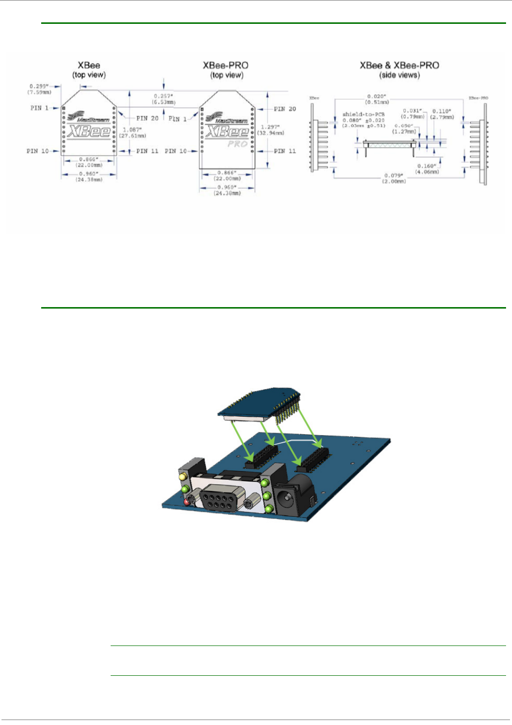
1.3. Mechanical Drawings
Figure1‐01. MechanicaldrawingsoftheXBee®/XBee‐PRO®900OEMRFModules(antennaoptionsnotshown)
.
1.4. Mounting Considerations
The XBee®/XBee-PRO® 900 RF Module (through-hole) was designed to mount into a receptacle
(socket) and therefore does not require any soldering when mounting it to a board. The
Development Kits contain RS-232 and USB interface boards which use two 20-pin receptacles to
receive modules.
Figure1‐02. XBeeSeries2PROModuleMountingtoanRS‐232InterfaceBoard.
The receptacles used on Digi development boards are manufactured by Century Interconnect.
Several other manufacturers provide comparable mounting solutions; however, Digi currently uses
the following receptacles:
• Through-hole single-row receptacles -
Samtec P/N: MMS-110-01-L-SV (or equivalent)
• Surface-mount double-row receptacles -
Century Interconnect P/N: CPRMSL20-D-0-1 (or equivalent)
• Surface-mount single-row receptacles -
Samtec P/N: SMM-110-02-SM-S
Digi also recommends printing an outline of the module on the board to indicate the orientation the
module should be mounted.

XBee®/XBee‐PRO®900OEMRFModules
©2008DigiInternational,Inc. 7
1.5. Pin Signals
Figure1‐03. XBee®/XBee‐PRO®900RFModulePinNumber
(topsidesshown‐shieldsonbottom)
Design Notes:
• Minimum connections: VCC, GND, DOUT & DIN
• Minimum connections to support serial firmware upgrades: VCC, GND, DIN, DOUT, RTS & DTR
• Signal Direction is specified with respect to the module
• Module includes a 30k Ohm resistor attached to RESET
• Several of the input pull-ups can be configured using the PR command
• Unused pins should be left disconnected
Table1‐02. PinAssignmentsfortheXBee®/XBee‐PRO®900Modules
(Low‐assertedsignalsaredistinguishedwithahorizontallineabovesignalname.)
Pin # Name Direction Description
1 VCC - Power supply
2 DOUT Output UART Data Out
3 DIN / CONFIG Input UART Data In
4 DIO12 Either Digital I/O 12
5RESET Input Module Reset (reset pulse must be at least 200 ns)
6 PWM0 / RSSI / DIO10 Either PWM Output 0 / RX Signal Strength Indicator / Digital IO
7 PWM / DIO11 Either Digital I/O 11
8 [reserved] - Do not connect
9DTR
/ SLEEP_RQ/ DIO8 Either Pin Sleep Control Line or Digital IO 8
10 GND - Ground
11 DIO4 Either Digital I/O 4
12 CTS / DIO7 Either Clear-to-Send Flow Control or Digital I/O 7
13 ON / SLEEP / DIO9 Output Module Status Indicator or Digital I/O 9
14 [reserved] - Do not connect
15 Associate / DIO5 Either Associated Indicator, Digital I/O 5
16 RTS / DIO6 Either Request-to-Send Flow Control, Digital I/O
17 AD3 / DIO3 Either Analog Input 3 or Digital I/O 3
18 AD2 / DIO2 Either Analog Input 2 or Digital I/O 2
19 AD1 / DIO1 Either Analog Input 1 or Digital I/O 1
20 AD0 / DIO0 / ID Button Either Analog Input 0, Digital I/O 0, or Node Identification

XBee®/XBee‐PRO®900OEMRFModules
©2008DigiInternational,Inc. 8
1.6. Electrical Characteristics
Table1‐03. DCCharacteristicsoftheXBee®/XBee‐PRO®900(VCC=2.8‐3.4VDC)
Symbol Parameter Condition Min Typical Max Units
VIL Input Low Voltage All Digital Inputs - - 0.2 * VCC V
VIH Input High Voltage All Digital Inputs 0.8 * VCC - - V
VOL Output Low Voltage IOL = 2 mA, VCC >= 2.7 V - - 0.18*VCC V
VOH Output High Voltage IOH = 2 mA, VCC >= 2.7 V 0.82*VCC - - V
IIIN Input Leakage Current VIN = VCC or GND, all inputs, per pin - - 0.5uA uA
©2008DigiInternational,Inc. 9
2.RFModuleOperation
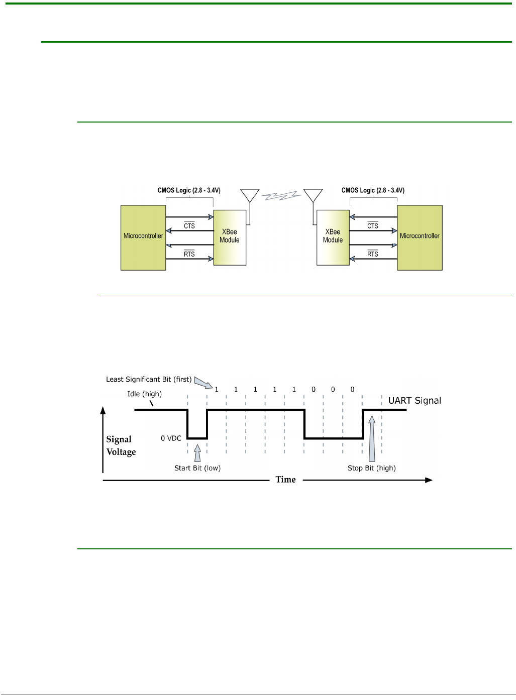
2.1. Serial Communications
The XBee®/XBee-PRO®OEM RF Modules interface to a host device through a logic-level
asynchronous serial port. Through its serial port, the module can communicate with any logic and
voltage compatible UART; or through a level translator to any serial device (For example: Through
a Digi proprietary RS-232 or USB interface board).
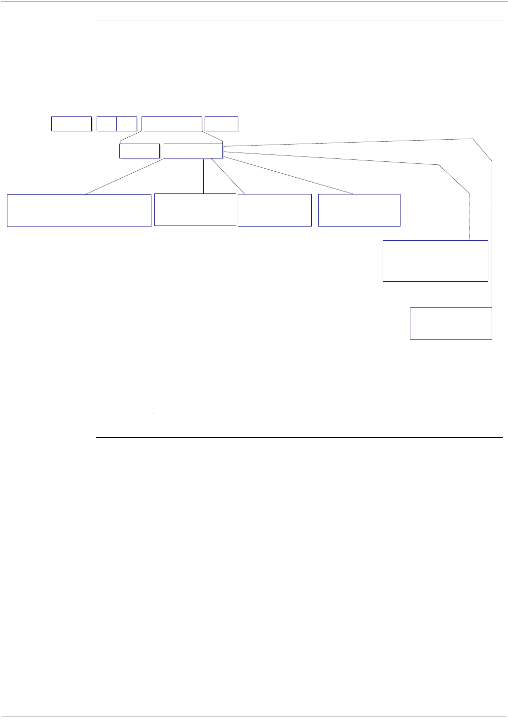
2.1.1. UART Data Flow
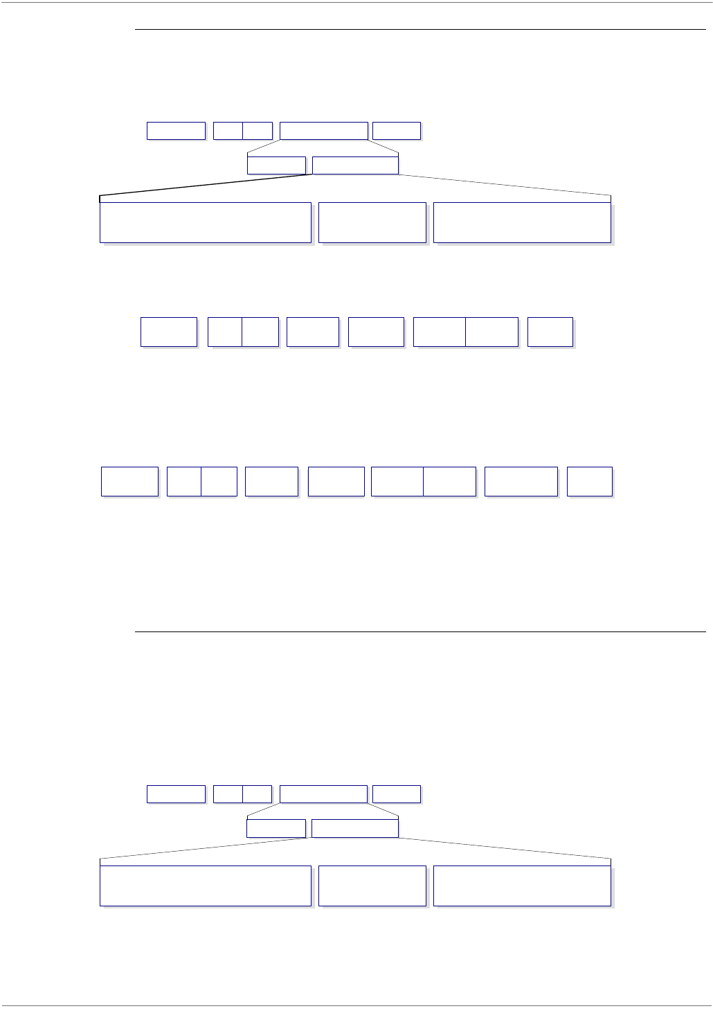
Devices that have a UART interface can connect directly to the pins of the RF module as shown in
the figure below.
Figure2‐01. SystemDataFlowDiagraminaUART‐interfacedenvironment
(Low‐assertedsignalsdistinguishedwithhorizontallineoversignalname.)
Serial Data
Data enters the module UART through the DIN (pin 3) as an asynchronous serial signal. The signal
should idle high when no data is being transmitted.
Each data byte consists of a start bit (low), 8 data bits (least significant bit first) and a stop bit
(high). The following figure illustrates the serial bit pattern of data passing through the module.
Figure2‐02. UARTdatapacket0x1F(decimalnumberʺ31ʺ)astransmittedthroughtheRFmodule
ExampleDataFormatis8‐N‐1(bits‐parity‐#ofstopbits)
The module UART performs tasks, such as timing and parity checking, that are needed for data
communications. Serial communications depend on the two UARTs to be configured with
compatible settings (baud rate, parity, start bits, stop bits, data bits).
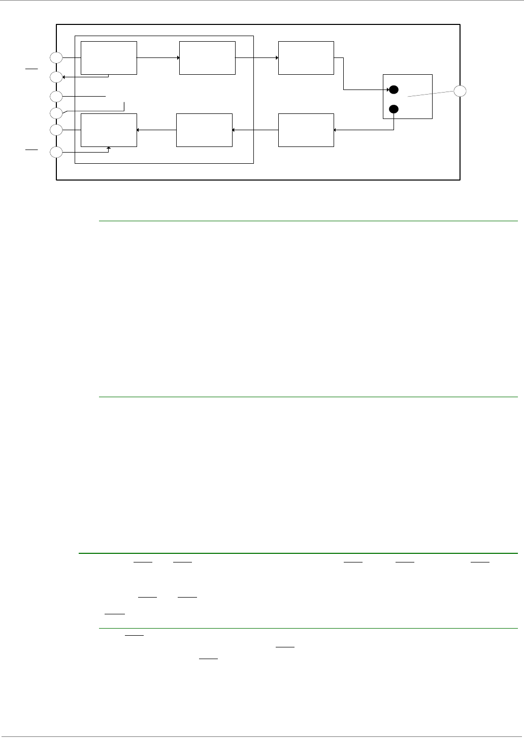
2.1.2. Serial Buffers
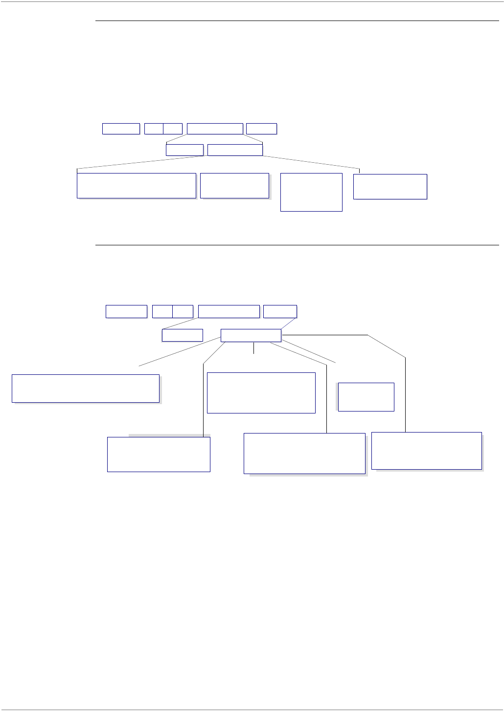
The XBee modules maintain buffers to collect received serial and RF data, which is illustrated in
the figure below. The serial receive buffer collects incoming serial characters and holds them until
they can be processed. The serial transmit buffer collects data that is received via the RF link that
will be transmitted out the UART.
DIN (data in) DIN (data in)
DOUT (data out) DOUT (data out)
XBee®/XBee‐PRO®900OEMRFRFModules
©2008DigiInternational,Inc. 10
Figure2‐03. InternalDataFlowDiagram
Serial Receive Buffer
When serial data enters the RF module through the DIN Pin (pin 3), the data is stored in the serial
receive buffer until it can be processed. Under certain conditions, the module may not be able to
process data in the serial receive buffer immediately. If large amounts of serial data are sent to
the module, CTS flow control may be required to avoid overflowing the serial receive buffer.
Cases in which the serial receive buffer may become full and possibly overflow:
1. If the module is receiving a continuous stream of RF data, the data in the serial receive buffer
will not be transmitted until the module is no longer receiving RF data.
2. If the module is transmitting an RF data packet, the module may need to discover the
destination address or establish a route to the destination. After transmitting the data, the module
may need to retransmit the data if an acknowledgment is not received, or if the transmission is a
broadcast. These issues could delay the processing of data in the serial receive buffer.
Serial Transmit Buffer
When RF data is received, the data is moved into the serial transmit buffer and is sent out the
serial port. If the serial transmit buffer becomes full enough such that all data in a received RF
packet won’t fit in the serial transmit buffer, the entire RF data packet is dropped.
Cases in which the serial transmit buffer may become full resulting in dropped RF
packets
If the RF data rate is set higher than the interface data rate of the module, the module could
receive data faster than it can send the data to the host.
If the host does not allow the module to transmit data out from the serial transmit buffer because
of being held off by hardware flow control.
2.1.3. Serial Flow Control
The RTS and CTS module pins can be used to provide RTS and/or CTS flow control. CTS flow
control provides an indication to the host to stop sending serial data to the module. RTS flow
control allows the host to signal the module to not send data in the serial transmit buffer out the
uart. RTS and CTS flow control are enabled using the D6 and D7 commands.
CTS Flow Control
If CTS flow control is enabled (D7 command), when the serial receive buffer is 17 bytes away
from being full, the module de-asserts CTS (sets it high) to signal to the host device to stop
sending serial data. CTS is re-asserted after the serial receive buffer has 34 bytes of space.
Serial
Receiver
Buffer
RF TX
Buffer Transmitter
RF Switch
Antenna
Port
Receiver
Serial Transmit
Buffer
RF RX
Buffer
Processor
GND
DIN
VCC
DOUT
CTS
RTS

XBee®/XBee‐PRO®900OEMRFRFModules
©2008DigiInternational,Inc. 11
RTS Flow Control
If flow RTS control is enabled (D6 command), data in the serial transmit buffer will not be sent
out the DOUT pin as long as RTS is de-asserted (set high). The host device should not de-assert
RTS for long periods of time to avoid filling the serial transmit buffer. If an RF data packet is
received, and the serial transmit buffer does not have enough space for all of the data bytes, the
entire RF data packet will be discarded.Transparent Operation
When operating in Transparent Mode, the modules act as a serial line replacement. All UART data
received through the DIN pin is queued up for RF transmission. When RF data is received, the data
is sent out the DOUT pin. The module configuration parameters are configured using the AT
command mode interface. (See RF Module Operation --> Command Mode.)
When RF data is received by a module, the data is sent out the DOUT pin.
Serial-to-RF Packetization
Data is buffered in the serial receive buffer until one of the following causes the data to be
packetized and transmitted:
No serial characters are received for the amount of time determined by the RO (Packetization
Timeout) parameter. If RO = 0, packetization begins when a character is received.
Maximum number of characters that will fit (72) in an RF packet is received.
The Command Mode Sequence (GT + CC + GT) is received. Any character buffered in the serial
receive buffer before the sequence is transmitted.
2.1.4. API Operation
API (Application Programming Interface) Operation is an alternative to the default Transparent
Operation. The frame-based API extends the level to which a host application can interact with the
networking capabilities of the module. When in API mode, all data entering and leaving the
module is contained in frames that define operations or events within the module.
Transmit Data Frames (received through the DIN pin (pin 3)) include:
• RF Transmit Data Frame
• Command Frame (equivalent to AT commands)
Receive Data Frames (sent out the DOUT pin (pin 2)) include:
• RF-received data frame
• Command response
• Event notifications such as reset, associate, disassociate, etc.
The API provides alternative means of configuring modules and routing data at the host
application layer. A host application can send data frames to the module that contain address and
payload information instead of using command mode to modify addresses. The module will send
data frames to the application containing status packets; as well as source, and payload
information from received data packets.
The API operation option facilitates many operations such as the examples cited below:
->Transmitting data to multiple destinations without entering Command Mode
->Receive success/failure status of each transmitted RF packet
->Identify the source address of each received packet
To implement API operations, refer to the API Operation chapter 6.
XBee®/XBee‐PRO®900OEMRFRFModules
©2008DigiInternational,Inc. 12
2.2. Modes of Operation
2.2.1. Idle Mode
When not receiving or transmitting data, the RF module is in Idle Mode. During Idle Mode, the RF
module is also checking for valid RF data. The module shifts into the other modes of operation
under the following conditions:
• Transmit Mode (Serial data in the serial receive buffer is ready to be packetized)
• Receive Mode (Valid RF data is received through the antenna)
• Command Mode (Command Mode Sequence is issued)
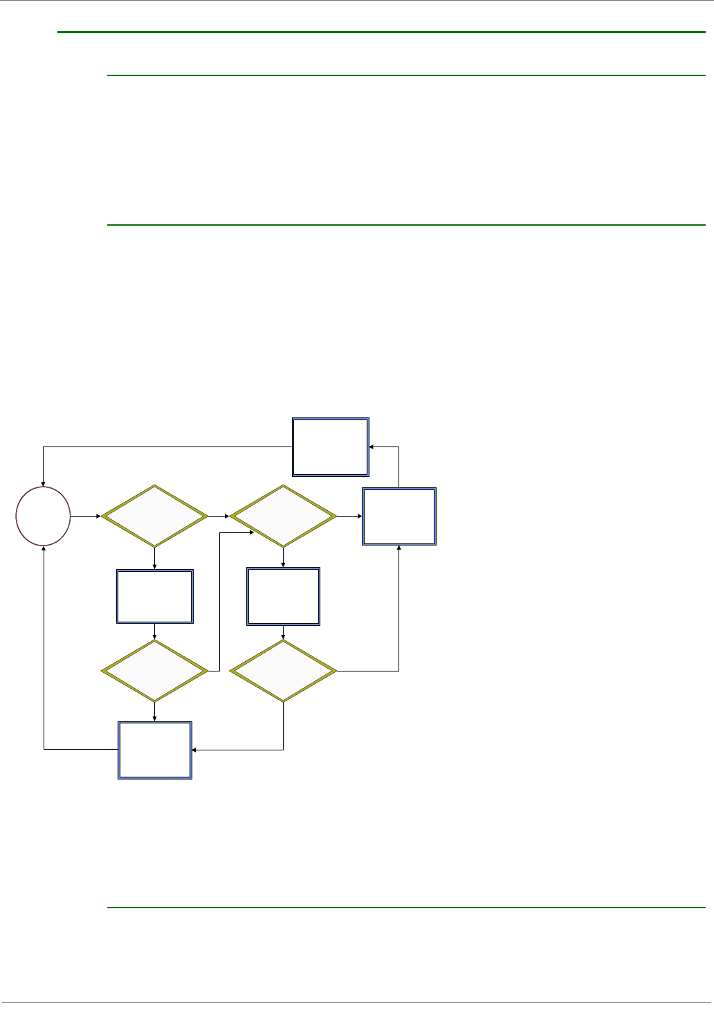
2.2.2. Transmit Mode
When serial data is received and is ready for packetization, the RF module will exit Idle Mode and
attempt to transmit the data. The destination address determines which node(s) will receive the
data.
Prior to transmitting the data, the module ensures that a 16-bit network address and route to the
destination node have been established.
If a route is not known, route discovery will take place for the purpose of establishing a route to
the destination node. If a module with a matching network address is not discovered, the packet is
discarded. The data will be transmitted once a route is established. If route discovery fails to
establish a route, the packet will be discarded.
Figure2‐04. TransmitModeSequence
When data is transmitted from one node to another, a network-level acknowledgement is
transmitted back across the established route to the source node. This acknowledgement packet
indicates to the source node that the data packet was received by the destination node. If a
network acknowledgement is not received, the source node will re-transmit the data. See Data
Transmission and Routing in chapter 3 for more information.
2.2.3. Receive Mode
If a valid RF packet is received, the data is transferred to the serial transmit buffer
16-bit Network
Address Discovery
Data Discarded
Successful
Transmission
Yes
No
New
Transmission
16-bit Network
Address Discovered?
Route Known?
Route Discovered?
16-bit Network
Address Known?
Route Discovery
Transmit Data
Idle Mode
No
Yes
No No
Yes Yes
XBee®/XBee‐PRO®900OEMRFRFModules
©2008DigiInternational,Inc. 13
2.2.4. Command Mode
To modify or read RF Module parameters, the module must first enter into Command Mode - a
state in which incoming serial characters are interpreted as commands. Refer to the API Mode
section for an alternate means of configuring modules.
AT Command Mode
To Enter AT Command Mode:
Send the 3-character command sequence “+++” and observe guard times before and after the
command characters. [Refer to the “Default AT Command Mode Sequence” below.]
Default AT Command Mode Sequence (for transition to Command Mode):
• No characters sent for one second [GT (Guard Times) parameter = 0x3E8]
• Input three plus characters (“+++”) within one second [CC (Command Sequence Character)
parameter = 0x2B.]
• No characters sent for one second [GT (Guard Times) parameter = 0x3E8]
All of the parameter values in the sequence can be modified to reflect user preferences.
NOTE: Failure to enter AT Command Mode is most commonly due to baud rate mismatch. Ensure the
‘Baud’ setting on the “PC Settings” tab matches the interface data rate of the RF module. By default,
the BD parameter = 3 (9600 bps).
To Send AT Commands:
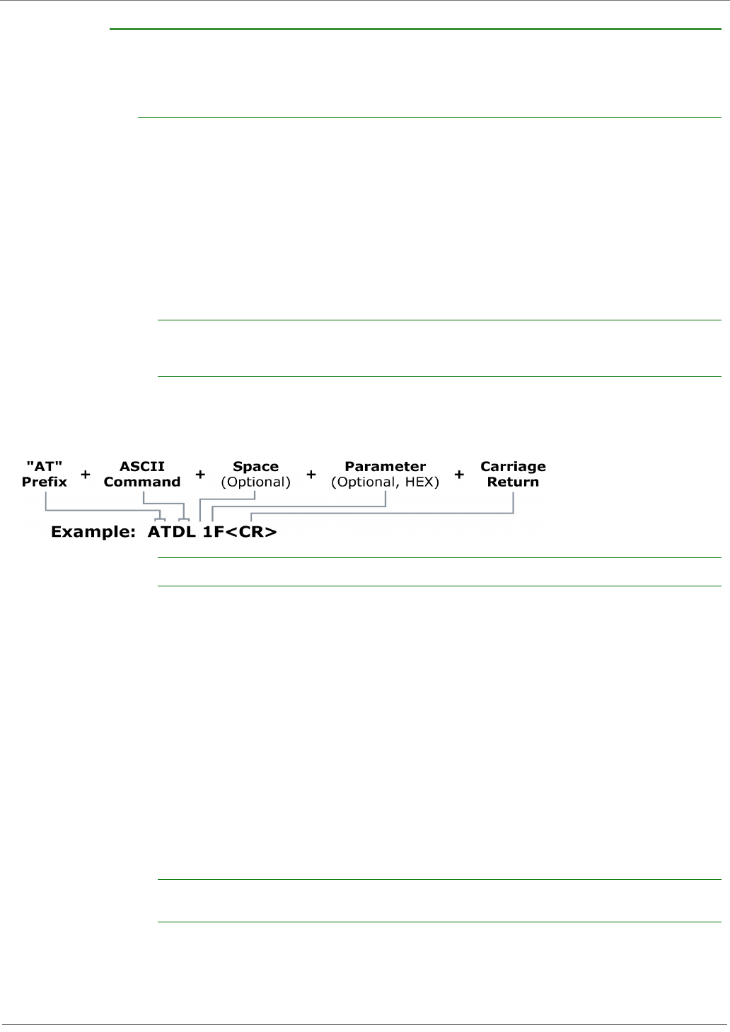
Send AT commands and parameters using the syntax shown below.
Figure2‐05.SyntaxforsendingATCommands
To read a parameter value stored in the RF module’s register, omit the parameter field.
The preceding example would change the RF module Destination Address (Low) to “0x1F”. To
store the new value to non-volatile (long term) memory, subsequently send the WR (Write)
command.
For modified parameter values to persist in the module’s registry after a reset, changes must be
saved to non-volatile memory using the WR (Write) Command. Otherwise, parameters are
restored to previously saved values after the module is reset.
System Response. When a command is sent to the module, the module will parse and execute
the command. Upon successful execution of a command, the module returns an “OK” message. If
execution of a command results in an error, the module returns an “ERROR” message.
To Exit AT Command Mode:
1. Send the ATCN (Exit Command Mode) command (followed by a carriage return).
[OR]
2. If no valid AT Commands are received within the time specified by CT (Command Mode
Timeout) Command, the RF module automatically returns to Idle Mode.
For an example of programming the RF module using AT Commands and descriptions of each config-
urable parameter, refer to the "Examples" and "Command Reference Tables" chapters.

©2008DigiInternational,Inc. 14
3.XBee900DigiMesh
3.1. Digi Mesh Networking
Mesh networking allows message to be routed through several different nodes to a final
destination. The MeshX firmware allows OEMs and system integrators to bolster their networks
with the self-healing attributes of mesh networking. In the event that one RFconnection between
nodes is lost (due to power-loss, environmental obstructions, etc.) critical data can still reach its
destination due to the mesh networking capabilities embedded inside the modules.
3.2. Digi Mesh Feature Set
Digi Mesh contains the following features
•Self-healing
Any node may enter or leave the network at any time without causing the network as a whole
to fail.
•Peer-to-peer architecture
No hierarchy and no parent-child relationships are needed.
•Quiet Protocol
Routing overhead will be reduced by using a reactive protocol similar to AODV.
•Route Discovery
Rather than maintaining a network map, routes will be discovered and created only when
needed.
•Selective acknowledgements
Only the destination node will reply to route requests
•Reliable delivery
Reliable delivery of data is accomplished by means of acknowledgements.
• Unicast and Broadcast addressing supported
Note that Sleep (low power) modes are not currently supported.
3.3. Data Transmission and Routing
3.3.1. Unicast Addressing
When transmitting while using Unicast communications, reliable delivery of data is accomplished
using retries and acknowledgements. The number of retries isdetermined by the NR (Network
Retries) parameter.RF data packets are sent up to NR + 1 times and ACKs (acknowledgements)
are transmitted by the receiving module upon receipt.
Refer to the DL (Destination Address Low) and DH (Destination Address High) parameters
forinformation on how to configure a module to operate using Unicast addresses.
All transmissions are addressed at the MAC layer.
When a new Unicast is given to the MAC layer for transmission, the following will occur:
• The MAC header is pre-pended.
• If incomplete transmissions precede it with the same destination address, the RF data packet
is placed on a pending queue.

XBee®/XBee‐PRO®900OEMRFModules
©2008DigiInternational,Inc. 15
3.3.2. Random Exponential Back off
The back-off is random because the number of delay slots (RN parameter) between retries (RR
parameter) is random. The backoff is exponential because the range of the number of the random
number of delay slots doubles with each retry. Note that the randomness allows the backoff time
to decrease from one retry to the next. However, because of the exponent, the backoff can quickly
grow very large.
The number of time slots when the transmission can occur doubles with each retry; but the actual
time between retries may be more or less than double the previous retry.
3.3.3. Broadcast Addressing
When operating in Broadcast Mode, reliable delivery of RF data packets is accomplished using
multiple transmissions. When transmitting in Broadcast mode, ACKs are not returned upon receipt
of an RF data packet. Retries don't apply to broadcasts because no acknowledgements will be
used.
The delay between retransmissions is a random number of delay slots in the range between 0 and
RN (“Delay Slots” parameter). After a Broadcast is sent RR + 1 times, a function will be called to
indicate a successful transmission.
3.3.4. Routing
A module within a Mesh network is able to determine reliable routes using a routing algorithm and
table. The routing algorithm uses a reactive method derived from AODV (Ad-hoc On-demand
Distance Vector). An associative routing table is used to map a destination node address with its
next hop. By sending a message to the next hop address, either the message will reach its
destination or be forwarded to an intermediate node which will route the message on to its
destination. A message with a Broadcast address is broadcast to all neighbors. All receiving
neighbors will rebroadcast the message and eventually the message will reach all corners of the
network. Packet tracking prevents a node from resending a broadcast message twice.
A message with a Unicast destination node address is looked up in an associative routing table. If
the destination address is not found and the message came here from a neighboring node; then a
routing error has occurred and the undeliverable message is dropped. An ACK timeout will
eventually occur at the source node and route discovery (RD) will be launched to re-establish the
route.
If the message originated with this node and RD is already underway to discover a route to the
destination; then the message is saved until RD is completed. If no route discovery is underway
and the route to the destination is unavailable, then the message is saved and RD is launched to
establish a route to the destination. When route discovery is over, the routing table will be
updated and the message relayed.
3.3.5. Route Discovery
If the source node doesn’t have a route to the requested destination, the packet is queued to
await a route discovery (RD) process.
RD begins by the source node broadcasting a route request (RREQ). Any node that receives the
RREQ that is not the ultimate destination is called an intermediate node.
Intermediate nodes may either drop or forward a RREQ, depending on whether the new RREQ has
a better route back to the source node. If so, information from the RREQ is saved and the RREQ is
updated and broadcast. When the ultimate destination receives the RREQ, it unicasts a route reply
(RREP) back to the source node along the path of the RREQ. This is done regardless of route
quality and regardless of how many times an RREQ has been seen before.
This allows the source node to receive multiple route replies. After a calculated wait time, the
source node selects the route with the best round trip route quality, which it will use for the
queued packet and for subsequent packets with the same destination address.

XBee®/XBee‐PRO®900OEMRFModules
©2008DigiInternational,Inc. 16

©2008DigiInternational,Inc. 17
4.XBee900

©2008DigiInternational,Inc. 18
5.XBeeCommandReferenceTables
Special
Addressing
Table5‐01. SpecialCommands
AT
Command Name and Description Parameter Range Default
WR
Write. Write parameter values to non-volatile memory so that parameter modifications
persist through subsequent resets.
Note: Once WR is issued, no additional characters should be sent to the module until
after the "OK\r" response is received.
-- --
RE Restore Defaults. Restore module parameters to factory defaults. RE command does
not reset the ID parameter. -- --
FR
Software Reset. Reset module. Responds immediately with an “OK” then performs a
reset ~2 seconds later. Use of the FR command will cause a network layer restart on the
node if SC or ID were modified since the last reset.
-- --
AC Apply Changes. Immediately applies new settings without exiting command mode. -- --
R1 Restore Compiled. Restore module parameters to compiled defaults. -- --
VL Version Long. Shows detailed version information including application build date and
time. -- --
Table5‐02. AddressingCommands)
AT
Command Name and Description Parameter Range Default
DH Destination Address High. Set/Get the upper 32 bits of the 64-bit destination address.
When combined with DL, it defines the destination address used for transmission. 0 to 0xFFFFFFFF 0x01010101
DL
Destination Address Low. Set/Get the lower 32 bits of the 64-bit destination address.
When combined with DH, DL defines the destination address used for transmission. DL
is not supported in API Mode.
0 to 0xFFFFFFFF 0x00000000
SH
Serial Number High. Read high 32 bits of the RF module's unique IEEE 64-bit
address. 64-bit source address is always enabled. This value is read-only and it never
changes
0x01010101 0x01010101
SL
Serial Number Low. Read low 32 bits of the RF module's unique IEEE 64-bit address.
64-bit source address is always enabled . This is read only and it is also the serial
number of the node. .
0 to 0xFFFFFFFF --
NI
Node Identifier. Stores a string identifier. The register only accepts printable ASCII
data. In AT Command Mode, a string can not start with a space. A carriage return ends
the command. Command will automatically end when maximum bytes for the string
have been entered. This string is returned as part of the ND (Node Discover) command.
This identifier is also used with the DN (Destination Node) command.
20-Byte printable
ASCII string --
ZA
ZigBee Application Layer Addressing. Set/read the Zigbee application layer
addressing enabled attribute. If enabled, data packets will use the SE, DE, and CI
commands to address Zigbee application layer source and destination endpoints, and
the cluster ID fields in all data transmissions. ZA is only supported in the AT firmware.
0 - 1 0
SE
Source Endpoint. Set/read the ZigBee application layer source endpoint value. If
ZigBee application layer addressing is enabled (ZA command), this value will be used
as the source endpoint for all data transmissions. SE is only supported in AT
firmware.The default value 0xE8 (Data endpoint) is the Digi data endpoint
1 - 0xEF 0xE8
DE
Destination Endpoint. Set/read Zigbee application layer destination ID value. If
ZigBee application layer addressing is enabled (ZA command), this value will be used
as the destination endpoint all data transmissions. DE is only supported in AT
firmware.The default value (0xE8) is the Digi data endpoint.
1-0xF0 0xE8
CI
Cluster Identifier. Set/read Zigbee application layer cluster ID value. If ZigBee
application layer addressing is enabled (ZA command), this value will be used as the
cluster ID for all data transmissions. CI is only supported in AT firmware.The default
value0x11 (Transparent data cluster ID).
0-0xFFFF 0x0011

XBee®/XBee‐PRO®900OEMRFModules
©2008DigiInternational,Inc. 19
Serial Interfacing (I/O)
Table5‐03. SerialInterfacingCommands
AT
Command Name and Description Parameter Range Default
AP
API mode. Set or read the API mode of the radio. The following settings are allowed:
0 API mode is off. All UART input and output is raw data and packets are delineated
using the RO and RB parameters.
1 API mode is on. All UART input and output data is packetized in the API format,
without escape sequences.
2 API mode is on with escaped sequences inserted to allow for control characters (XON,
XOFF, escape, and the 0x7e delimiter to be passed as data.
0, 1, or 2 0
AO
API Output Format. Enables different API output frames. Options include:
0 ZigBee Standard Data Frames (0x90 for RF rx)
1 ZigBee Explicit Addressing Data Frames (0x91 for RF rx) 0, 1 0
BD
Baud rate. Set or read serial interface rate (speed for data transfer between radio
modem and host). Values from 0-8 select preset standard rates. Values at 0x39 and
above select the actual baud rate. Providing the host supports it. Baud rates can go as
high as 1.875Mbps. The values from 0 to 8 are interpreted as follows:
0 - 1,200bps 3 - 9,600bps 6 - 57,600bps
1 - 2,400bps 4 - 19,200bps 7 - 115,200bps
2 - 4,800bps 5 - 38,400bps 8 - 230,400bps
0 to 8, and 0x39 to
0x1c9c38
0x03 (9600
bps)
RO
Packetization Timeout. Set/Read number of character times of inter-character silence
required before packetization. Set (RO=0) to transmit characters as they arrive instead of
buffering them into one RF packet.
0 - 0xFF
[x character times] 3
FT
Flow Control Threshhold. Set or read flow control threshhold. De-assert CTS and/or
send XOFF when FT bytes are in the UART receive buffer. Re-assert CTS when less
than FT - 16 bytes are in the UART receive buffer.
17 to 382 0x016D =
365
GT
Command Guard Time. Set required period of silence before and after the Command
Mode Characters of the Command Mode Sequence (GT + CC + GT). The period of
silence is used to prevent inadvertent entrance into AT Command Mode. If the GT time is
less than RO time at the baud rate, then RO time will be used for GT time.
0 to 0xFFFF 0x3E8
ME
Mesh Enable. Enable Digi Mesh network layer. Otherwise the application bypasses the
Mesh layer and goes directly to the mac layer. All radios that wish to communicate must
have the same setting.
0 to 1 0
NB
Parity. Set or read parity settings for UART communications. The values from 0 to 4 are
interpreted as follows:
0 No parity 3 Forced high parity
1 Even parity 4 Forced low parity
2 Odd parity
0 to 4 0 (No parity)
SB
Stop Bits. Set or read number of stop bits used for UART communications. The values
from 0 to 4 are interpreted as follows:
0 - 1 stop bit 1 - 2 stop bits
0 to 1 0 (1 stop bit)
D7
DIO7 Configuration. Configure options for the DIO7 line of the module. Options include:
0 = Input, unmonitored
1 = CTS flow control
3 = Digital input, monitored
4 = Digital output low
5 = Digital output high
6 = RS-485 Tx enable, low TX (0V on transmit, high when idle)
7 = RS-485 Tx enable, high TX (high on transmit, 0V when idle)
0-1, 3-7 0
D6
DIO6 Configuration. Configure options for the DIO6 line of the module. Options include:
0 = Input, unmonitored
1 = RTS flow control
3 = Digital input, monitored
4 = Digital output low
5 = Digital output high
0-1, 3-5 0
D5
AD5/DIO5 Configuration. Configure options for the AD5/DIO5 line of the module.
Options include:
0 = Input, unmonitored
1 = Power LED output
3 = Digital input, monitored
4 = Digital output low
5 = Digital output high
0-1, 3-5 1

XBee®/XBee‐PRO®900OEMRFModules
©2008DigiInternational,Inc. 20
I/O Commands
Table5‐04. I/OCommands
AT
Command Name and Description Parameter Range Default
P0
DIO10/PWM0 Configuration. Configure options for the DIO10/PWM0 line of the
module. Options include:
0 = Input, unmonitored
1 = RSSI
2 = PWM0
3 = Digital input, monitored
4 = Digital output low
5 = Digital output high
0-5 1
P1
DIO11/PWM1 Configuration. Configure options for the DIO11/PWM1 line of the
module. Options include:
0 = Input, unmonitored
2 = PWM1
3 = Digital input, monitored
4 = Digital output low
5 = Digital output high
0, 2-5 0
P2
DIO12 Configuration. Configure options for the DIO12 line of the module. Options
include:
0 = Input, unmonitored
3 = Digital input, monitored
4 = Digital output low
5 = Digital output high
0, 3-5 0
???RP RSSI PWM Timer. Time RSSI signal will be output after last transmission. When RP =
0xFF, output will always be on. 0 - 0xFF [x 100 ms] 0x28 (40d)
D0
AD0/DIO0 Configuration. Configure options for the AD0/DIO0 line of the module.
Options include:
0 = Input, unmonitored
3 = Digital input, monitored
4 = Digital output low
5 = Digital output high
0, 3-5 0
D1
AD1/DIO1 Configuration. Configure options for the AD1/DIO1 line of the module.
Options include:
0 = Input, unmonitored
3 = Digital input, monitored
4 = Digital output low
5 = Digital output high
0, 3-5 0
D2
AD2/DIO2 Configuration. Configure options for the AD2/DIO2 line of the module.
Options include:
0 = Input, unmonitored
3 = Digital input, monitored
4 = Digital output low
5 = Digital output high
0, 3-5 0
D3
AD3/DIO3 Configuration. Configure options for the AD3/DIO3 line of the module.
Options include:
0 = Input, unmonitored
3 = Digital input, monitored
4 = Digital output low
5 = Digital output high
0, 3-5 0
D4
AD4/DIO4 Configuration. Configure options for the AD4/DIO4 line of the module.
Options include:
0 = Input, unmonitored
3 = Digital input, monitored
4 = Digital output low
5 = Digital output high
0, 3-5 0

XBee®/XBee‐PRO®900OEMRFModules
©2008DigiInternational,Inc. 21
Diagnostics
AT Command Options
Digi Mesh: Networking & Security
PR
Set/read the bit field that configures the internal pull-up resistor status for the I/O lines.
"1" specifies the pull-up resistor is enabled. "0" specifies no pullup.
Bits:"
0 - DIO4 (Pin 11)
1 - AD3 / DIO3 (Pin 17)
2 - AD2 / DIO2 (Pin 18)
3 - AD1 / DIO1 (Pin 19)
4 - AD0 / DIO0 (Pin 20)
5 - RTS / DIO6 (Pin 16)
6 - DTR / Sleep Request / DIO8 (Pin 9)
7 - DIN / Config (Pin 3)
8 - Associate / DIO5 (Pin 15)
9 - On/Sleep / DIO9 (Pin 13)
10 - DIO12 (Pin 4)
11 - PWM0 / RSSI / DIO10 (Pin 6)
12 - PWM1 / DIO11 (Pin 7)
0 - 0x1FFF 0 - 0x1FFF
Table5‐05. DiagnosticsCommands
AT
Command Name and Description Parameter Range Default
VR Firmware Version. Read firmware version of the module. 0 - 0xFFFF [read-only] Factory-set
HV Hardware Version. Read hardware version of the module. 0 - 0xFFFF [read-only] Factory-set
%V
Supply Voltage. Reads the voltage on the Vcc pin. To convert the reading to a mV
reading, divide the read value by 1023 and multiply by 1200. A %V reading of 0x8FE
(2302 decimal) represents 2700mV or 2.70V.
--
Table5‐06. ATCommandOptionsCommands
AT
Command Name and Description Parameter Range Default
CT
Command Mode Timeout. Set/Read the period of inactivity (no valid commands
received) after which the RF module automatically exits AT Command Mode and returns
to Idle Mode.
2 - 0x028F [x 100 ms] 0x64 (100d)
CN Exit Command Mode. Explicitly exit the module from AT Command Mode. -- --
GT
Guard Times. Set required period of silence before and after the Command Sequence
Characters of the AT Command Mode Sequence (GT + CC + GT). The period of silence
is used to prevent inadvertent entrance into AT Command Mode.
1 - 0x0CE4 [x 1 ms]
(max of 3.3 decimal sec)
0x3E8
(1000d)
CC
Command Character. Set or read the character to be used between guard times of the
AT Command Mode Sequence. The AT Command Mode Sequence causes the radio
modem to enter Command Mode (from Idle Mode).
0 - 0xFF 0x2B
Table5‐07. NetworkingCommands
AT
Command Name and Description Parameter Range Default
ID
Network Identifier. Set or read the user network address. Nodes must have the same
network address to communicate. Changes to ID should be written to non-volatile
memory using the WR command.
0x0000 to 0x7FFF 0x7FFF
NT Node Discover Timeout. Set/Read the amount of time a node will spend discovering
other nodes when ND or DN is issued.
0 - 0xFC
[x 100 msec] 0x3C (60d)
ND
Node Identifier. Stores a string identifier. The string accepts only printable ASCII data
In AT Command Mode, the string can not start with a space. A Carriage return ends the
command. Command will automatically end when maximum bytes for the string have
been entered. This string is returned as part of the ATND (Network Discover) command.
This identifier is also used with the ATDN (Destination Node) command. .
20 byte ASCII string a space character
Table5‐04. I/OCommands
AT
Command Name and Description Parameter Range Default

XBee®/XBee‐PRO®900OEMRFModules
©2008DigiInternational,Inc. 22
DN
Destination Node. Resolves an NI (Node Identifier) string to a physical address (case-
sensitive). The following events occur after the destination node is discovered:
<AT Firmware>
1. DL & DH are set to the extended (64-bit) address of the module with the matching
NI (Node Identifier) string.
2. OK (or ERROR)\r is returned.
3. Command Mode is exited to allow immediate communication
If there is no response from a module within (NT * 100) milliseconds or a parameter is
not specified (left blank), the command is terminated and an “ERROR” message is
returned. In the case of an ERROR, Command Mode is not exited.
up to 20-Byte printable
ASCII string a space character
Table5‐07. NetworkingCommands
AT
Command Name and Description Parameter Range Default

©2008DigiInternational,Inc. 23
6.Antennas:900MHzAntennaListings
900 MHz Antenna Listings
Omni-directional antennas
Part Number Type Connector Gain Application
A09-F0 Fiberglass Base RPN 0 dBi Fixed
A09-F1 Fiberglass Base RPN 1.0 dBi Fixed
A09-F2 Fiberglass Base RPN 2.1 dBi Fixed
A09-F3 Fiberglass Base RPN 3.1 dBi Fixed
A09-F4 Fiberglass Base RPN 4.1 dBi Fixed
A09-F5 Fiberglass Base RPN 5.1 dBi Fixed
A09-F6 Fiberglass Base RPN 6.1 dBi Fixed
A09-F7 Fiberglass Base RPN 7.1 dBi Fixed
A09-F8 Fiberglass Base RPN 8.1 dBi Fixed
A09-F9 Base Station RPSMAF 9.2dBi Fixed
A09-W7 Wire Base Station RPN 7.1 dBi Fixed
A09-F0 Fiberglass Base RPSMA 0 dBi Fixed
A09-F1 Fiberglass Base RPSMA 1.0 dBi Fixed
A09-F2 Fiberglass Base RPSMA 2.1 dBi Fixed
A09-F3 Fiberglass Base RPSMA 3.1 dBi Fixed
A09-F4 Fiberglass Base RPSMA 4.1 dBi Fixed
A09-F5 Fiberglass Base RPSMA 5.1 dBi Fixed
A09-F6 Fiberglass Base RPSMA 6.1 dBi Fixed
A09-F7 Fiberglass Base RPSMA 7.1 dBi Fixed
A09-F8 Fiberglass Base RPSMA 8.1 dBi Fixed
A09-M7 Base Station RPSMAF 7.2dBi Fixed
A09-W7SM Wire Base Station RPSMA 7.1 dBi Fixed
A09-F0TM Fiberglass Base RPTNC 0 dBi Fixed
A09-F1TM Fiberglass Base RPTNC 1.0 dBi Fixed
A09-F2TM Fiberglass Base RPTNC 2.1 dBi Fixed
A09-F3TM Fiberglass Base RPTNC 3.1 dBi Fixed
A09-F4TM Fiberglass Base RPTNC 4.1 dBi Fixed
A09-F5TM Fiberglass Base RPTNC 5.1 dBi Fixed
A09-F6TM Fiberglass Base RPTNC 6.1 dBi Fixed
A09-F7TM Fiberglass Base RPTNC 7.1 dBi Fixed
A09-F8TM Fiberglass Base RPTNC 8.1 dBi Fixed
A09-W7TM Wire Base Station RPTNC 7.1 dBi Fixed
A09-HSM-7 Straight half-wave RPSMA 3.0 dBi Fixed / Mobile
A09-HASM-675 Articulated half-wave RPSMA 2.1 dBi Fixed / Mobile
A09-HABMM-P6I Articulated half-wave MMCX 2.1 dBi Fixed / Mobile
A09-HABMM-6-P6I Articulated half-wave MMCX 2.1 dBi Fixed / Mobile
A09-HBMM-P6I Straight half-wave w/ MMCX 2.1 dBi Fixed / Mobile
A09-HRSM Right angle half-wave RPSMA 2.1 dBi Fixed
A09-HASM-7 Articulated half-wave RPSMA 2.1 dBi Fixed

XBeeOEMRFModules
©2008DigiInternational,Inc. 24
A09-HG Glass mounted half- RPSMA 2.1 dBi Fixed
A09-HATM Articulated half-wave RPTNC 2.1 dBi Fixed
A09-H Half-wave dipole RPSMA 2.1 dBi Fixed
A09-HBMMP6I 1/2 wave antenna MMCX 2.1dBi Mobile
A09-QBMMP6I 1/4 wave antenna MMCX 1.9 dBi Mobile
A09-QI 1/4 wave integrated
wire antenna Integrated 1.9 dBi Mobile
29000187 Helical Integrated -2.0 dBi Fixed/Mobile
A09-QW Quarter-wave wire Permanent 1.9 dBi Fixed / Mobile
A09-QRAMM 3 “ Quarter-wave wire MMCX 2.1 dBi Fixed / Mobile
A09-QSM-3 Quarter-wave straight RPSMA 1.9 dBi Fixed / Mobile
A09-QSM-3H Heavy duty quarter- RPSMA 1.9 dBi Fixed / Mobile
A09-QBMM-P6I Quarter-wave w/ 6” MMCX 1.9 dBi Fixed / Mobile
A09-QHRN Miniature Helical Right Permanent -1 dBi Fixed / Mobile
A09-QHSN Miniature Helical Right Permanent -1 dBi Fixed / Mobile
A09-QHSM-2 2” Straight RPSMA 1.9 dBi Fixed / Mobile
A09-QHRSM-2 2" Right angle RPSMA 1.9 dBi Fixed / Mobile
A09-QHRSM-170 1.7" Right angle RPSMA 1.9 dBi Fixed / Mobile
A09-QRSM-380 3.8" Right angle RPSMA 1.9 dBi Fixed / Mobile
A09-QAPM-520 5.2” Articulated Screw Permanent 1.9 dBi Fixed / Mobile
A09-QSPM-3 3” Straight screw Permanent 1.9 dBi Fixed / Mobile
A09-QAPM-3 3” Articulated screw Permanent 1.9 dBi Fixed / Mobile
A09-QAPM-3H 3” Articulated screw Permanent 1.9 dBi Fixed / Mobile
A09-DPSM-P12F omni directional RPSMA 3.0 dBi Fixed
A09-D3NF-P12F omni directional RPN 3.0 dBi Fixed
A09-D3SM-P12F omni directional w/ 12ft RPSMA 3.0 dBi Fixed
A09-D3PNF omni directional RPN 3.0 dBi Fixed
A09-D3TM-P12F omni directional w/ 12ft RPTNC 3.0 dBi Fixed
A09-D3PTM omni directional RPTNC 3.0 dBi Fixed
A09-M0SM Mag Mount RPSMA 0 dBi Fixed
A09-M2SM Mag Mount RPSMA 2.1 dBi Fixed
A09-M3SM Mag Mount RPSMA 3.1 dBi Fixed
A09-M5SM Mag Mount RPSMA 5.1 dBi Fixed
A09-M7SM Mag Mount RPSMA 7.1 dBi Fixed
A09-M8SM Mag Mount RPSMA 8.1 dBi Fixed
A09-M0TM Mag Mount RPTNC 0 dBi Fixed
A09-M2TM Mag Mount RPTNC 2.1 dBi Fixed
A09-M3TM Mag Mount RPTNC 3.1 dBi Fixed
A09-M5TM Mag Mount RPTNC 5.1 dBi Fixed
A09-M7TM Mag Mount RPTNC 7.1 dBi Fixed
A09-M8TM Mag Mount RPTNC 8.1 dBi Fixed
Table Yagi antennas
Part Number Type Connector Gain Application
A09-Y6 2 Element Yagi RPN 6.1 dBi Fixed / Mobile
A09-Y7 3 Element Yagi RPN 7.1 dBi Fixed / Mobile
A09-Y8 4 Element Yagi RPN 8.1 dBi Fixed / Mobile
A09-Y9 4 Element Yagi RPN 9.1 dBi Fixed / Mobile
A09-Y10 5 Element Yagi RPN 10.1 dBi Fixed / Mobile

XBeeOEMRFModules
©2008DigiInternational,Inc. 25
A09-Y11 6 Element Yagi RPN 11.1 dBi Fixed / Mobile
A09-Y12 7 Element Yagi RPN 12.1 dBi Fixed / Mobile
A09-Y13 9 Element Yagi RPN 13.1 dBi Fixed / Mobile
A09-Y14 10 Element Yagi RPN 14.1 dBi Fixed / Mobile
A09-Y14 12 Element Yagi RPN 14.1 dBi Fixed / Mobile
A09-Y15 13 Element Yagi RPN 15.1 dBi Fixed / Mobile
A09-Y15 15 Element Yagi RPN 15.1 dBi Fixed / Mobile
A09-Y6TM 2 Element Yagi RPTNC 6.1 dBi Fixed / Mobile
A09-Y7TM 3 Element Yagi RPTNC 7.1 dBi Fixed / Mobile
A09-Y8TM 4 Element Yagi RPTNC 8.1 dBi Fixed / Mobile
A09-Y9TM 4 Element Yagi RPTNC 9.1 dBi Fixed / Mobile
A09-Y10TM 5 Element Yagi RPTNC 10.1 dBi Fixed / Mobile
A09-Y11TM 6 Element Yagi RPTNC 11.1 dBi Fixed / Mobile
A09-Y12TM 7 Element Yagi RPTNC 12.1 dBi Fixed / Mobile
A09-Y13TM 9 Element Yagi RPTNC 13.1 dBi Fixed / Mobile
A09-Y14TM 10 Element Yagi RPTNC 14.1 dBi Fixed / Mobile
A09-Y14TM 12 Element Yagi RPTNC 14.1 dBi Fixed / Mobile
A09-Y15TM 13 Element Yagi RPTNC 15.1 dBi Fixed / Mobile
A09-Y15TM 15 Element Yagi RPTNC 15.1 dBi Fixed / Mobile

©2008DigiInternational,Inc. 26
7.APIOperation
As an alternative to Transparent Operation, API (Application Programming Interface) Operations
are available. API operation requires that communication with the module be done through a
structured interface (data is communicated in frames in a defined order). The API specifies how
commands, command responses and module status messages are sent and received from the
module using a UART Data Frame.
7.0.1. API Frame Specifications
Two API modes are supported and both can be enabled using the AP (API Enable) command. Use
the following AP parameter values to configure the module to operate in a particular mode:
•AP = 1: API Operation
•AP = 2: API Operation (with escaped characters)
API Operation (AP parameter = 1)
When this API mode is enabled (AP = 1), the UART data frame structure is defined as follows:
Figure7‐01. UARTDataFrameStructure:
MSB=MostSignificantByte,LSB=LeastSignificantByte
Any data received prior to the start delimiter is silently discarded. If the frame is not received
correctly or if the checksum fails, the module will reply with a module status frame indicating the
nature of the failure.
API Operation - with Escape Characters (AP parameter = 2)
When this API mode is enabled (AP = 2), the UART data frame structure is defined as follows:
Figure7‐02. UARTDataFrameStructure‐withescapecontrolcharacters:
MSB=MostSignificantByte,LSB=LeastSignificantByte
Escape characters. When sending or receiving a UART data frame, specific data values must be
escaped (flagged) so they do not interfere with the data frame sequencing. To escape an
interfering data byte, insert 0x7D and follow it with the byte to be escaped XOR’d with 0x20.
Length
(Bytes 2-3)
Checksum
(Byte n + 1)
MSB LSB 1 Byte
Start Delimiter
(Byte 1)
0x7E
Frame Data
(Bytes 4-n)
API-specific Structure
Start Delimiter
(Byte 1)
Length
(Bytes 2-3)
Frame Data
(Bytes 4-n)
Checksum
(Byte n + 1)
0x7E MSB LSB API-specific Structure 1 Byte
Characters Escaped If Needed

XBee®/XBee‐PRO®900OEMRFModules]
©2008DigiInternational,Inc. 27
Data bytes that need to be escaped:
• 0x7E – Frame Delimiter
•0x7D – Escape
• 0x11 – XON
• 0x13 – XOFF
Note: In the above example, the length of the raw data (excluding the checksum) is 0x0002 and
the checksum of the non-escaped data (excluding frame delimiter and length) is calculated as:
0xFF - (0x23 + 0x11) = (0xFF - 0x34) = 0xCB.
Checksum
To test data integrity, a checksum is calculated and verified on non-escaped data.
To calculate: Not including frame delimiters and length, add all bytes keeping only the lowest 8
bits of the result and subtract the result from 0xFF.
To verify: Add all bytes (include checksum, but not the delimiter and length). If the checksum is
correct, the sum will equal 0xFF.
7.0.2. API Frames
Frame data of the UART data frame forms an API-specific structure as follows:
Figure7‐03. UARTDataFrame&API‐specificStructure:
The cmdID frame (API-identifier) indicates which API messages will be contained in the cmdData
frame (Identifier-specific data). Note that multi-byte values are sent big endian. The modules
support the following API frames:
Example - Raw UART Data Frame (before escaping interfering bytes):
0x7E 0x00 0x02 0x23 0x11 0xCB
0x11 needs to be escaped which results in the following frame:
0x7E 0x00 0x02 0x23 0x7D 0x31 0xCB
Table7‐08. APIFrameNamesandValu e s
API Frame Names Values
Modem Status 0x8A
Advanced Modem
Status 0x8C
AT Command 0x08
AT Command - Queue
Parameter Value 0x09
AT Command Response 0x88
Remote Command Request 0x17
Remote Command
Response 0x97
Transmit
Request 0x10
Explicit Addressing
Command
Frame
0x11
Transmit
Status 0x8B
Receive
Packet (AO=0) 0x90
Length
(Bytes 2-3)
Checksum
(Byte n + 1)
MSB LSB 1 Byte
Start Delimiter
(Byte 1)
0x7E
Frame Data
(Bytes 4-n)
API-specific Structure
Identifier-specific Data
cmdData
API Identifier
cmdID
XBee®/XBee‐PRO®900OEMRFModules]
©2008DigiInternational,Inc. 28
Modem Status
API Identifier Value: (0x8A)
RF module status messages are sent from the module in response to specific conditions.
Figure7‐04. ModemStatusFrames
Explicit Rx
Indicator (AO=1) 0x91
XBee Sensor Read
Indicator (AO=0) 0x94
Node Identification
Indicator (AO=0) 0x95
Table7‐08. APIFrameNamesandValu e s
API Frame Names Values
cmdData0x8A
Length ChecksumStart Delim iter Fram e D ata
Identifier-specific DataAPI Identifier
MSB LSB0x7E 1 ByteAPI-specific Structure
Status (Byte 5)
0 = Hardware reset
1 = Watchdog timer reset
2 = Associated
3 = Disassociated
4 = Synchronization Lost
(Beacon-enabled only)
5 = Coordinator realignment
6 = Coordinator started
XBee®/XBee‐PRO®900OEMRFModules]
©2008DigiInternational,Inc. 29
AT Command
API Identifier Value: (0x08)
Allows for module parameter registers to be queried or set.
Figure7‐5. ATCommandFrames
Figure7‐6. Example:APIframeswhenreadingtheNJparametervalueofthemodule.
Figure7‐7. Example:APIframeswhenmodifyingtheNJparametervalueofthemodule.
A string parameter used with the NI (Node Identifier), ND (Node Discover) and DH (Destination
Address High) command is terminated with a 0x00 character.
AT Command - Queue Parameter Value
API Identifier Value: (0x09)
This API type allows module parameters to be queried or set. In contrast to the “AT Command” API
type, new parameter values are queued and not applied until either the “AT Command” (0x08) API
type or the AC (Apply Changes) command is issued. Register queries (reading parameter values)
are returned immediately.
Figure7‐8. ATCommandFrames
(Notethatframesareidenticaltothe“ATCommand”APItypeexceptfortheAPIidentifier.)
cmdData0x08
Length ChecksumStart Delimiter Frame Data
Identifier-specific DataAPI Identifier
MSB LSB0x7E 1 ByteAPI-specific Structure
Frame ID (Byte 5)
Identifies the UART data frame for the host to
correlate with a subsequent ACK (acknowledgement).
If set to ‘0’, no response is sent.
AT Command (Bytes 6-7)
Command Name - Two
ASCII characters that
identify the AT Command.
Parameter Value (Byte(s) 8-n)
If present, indicates the requested parameter
value to set the given register.
If no characters present, register is queried.
*Length[Bytes]=APIIdentifier+FrameID+ATCommand
**“R”valuewasarbitrarilyselected.
Checksum
0x0D
Byte 8
AT Command
Bytes 6-7
Frame ID**
0x52 (R)
Byte 5
0x4E (N) 0x4A (J)
API Identifier
0x08
Byte 4
Start Delimiter
Byte 1
0x7E
Length*
Bytes 2-3
0x00 0x04
*Length[Bytes]=APIIdentifier+FrameID+ATCommand+ParameterValue
**“M”valuewasarbitrarilyselected.
Checksum
0xD2
Byte 9
AT Command
Bytes 6-7
0x4E (N) 0x4A (J)
Parameter Value
0x40
Bytes 8
Frame ID**
0x4D (M)
Byte 5
Length*
Bytes 2-3
0x00 0x05
API Identifier
0x08
Byte 4
Start Delimiter
Byte 1
0x7E
cmdData0x09
Length ChecksumStart Delimiter Frame Data
Identifier-specific DataAPI Identifier
MSB LSB0x7E 1 ByteAPI-specific Structure
Frame ID (Byte 5)
Identifies the UART data frame for the host to
correlate with a subsequent ACK (acknowledgement).
If set to ‘0’, no response is sent.
AT Command (Bytes 6-7)
Command Name - Two
ASCII characters that
identify the AT Command.
Parameter Value (Byte(s) 8-n)
If present, indicates the requested parameter
value to set the given register.
If no characters present, register is queried.
XBee®/XBee‐PRO®900OEMRFModules]
©2008DigiInternational,Inc. 30
AT Command Response
API Identifier Value: (0x88)
Response to previous command.
In response to an AT Command message, the module will send an AT Command Response
message. Some commands will send back multiple frames (for example, the ND (Node Discover)
command).
Figure7‐9. ATCommandResponseFrames.
Remote AT Command Request
API Identifier Value: (0x17)
Allows for module parameter registers on a remote device to be queried or set
Figure7‐10. RemoteATCommandRequest
cmdData0x88
Length ChecksumStart Delimiter Frame Data
Identifier-specific DataAPI Identifier
MSB LSB0x7E 1 ByteAPI-specific Structure
Frame ID (Byte 5 )
Identifies the UART data frame being reported.
Note: If Frame ID = 0 in AT Command Mode,
no AT Command Response will be given.
AT Command (Bytes 6-7)
Command Name - Two
ASCII characters that
identify the AT Command.
Status (Byte 8)
0 = OK
1 = ERROR
2 = Invalid Command
3 = Invalid Parameter
The HEX (non-ASCII) value
of the requested register
Value (Byte(s) 9-n)
16-bit Destination Network Address
(bytes 14-15)
Frame ID (Byte 5)
Identifies the UART data frame being
reported. If Frame ID = 0, no AT command
response will be given
cmdData
Length ChecksumStart Delimiter Frame Data
Identifier-specific Data
API Identifier
MSB LSB0x7E 1 ByteAPI-specific Structure
64-bit Destination Address
(bytes 6-13)
Set to match the 64-bit address
of the destination, MSB first,
LSB last. Broadcast =
0x000000000000FFFF.
Command Options (byte 16)
0x02 - Apply changes on remote. (If
not set, AC command must be sent
before changes will take effect.)
All other bits must be set to 0.
0x017
Command Data (byte 19-n)
If present, indicates the requested
parameter value to set the given
register. If no characters present,
the register is queried.
Set to match the 16-bit network
address of the destination, MSB
first, LSB last. Set to 0xFFFE for
broadcast TX, or if the network
address is unknown.
Command Name (bytes
17-18)
Name of the
command
XBee®/XBee‐PRO®900OEMRFModules]
©2008DigiInternational,Inc. 31
Remote Command Response
API Identifier Value: (0x97)
If a module receives a remote command response RF data frame in response to a Remote AT
Command Request, the module will send a Remote AT Command Response message out the UART.
Some commands may send back multiple frames--for example, Node Discover (ND) command.
Figure7‐11. RemoteATCommandResponse.
Transmit Request
API Identifier Value: (0x10) A TX Request message will cause the module to send RF Data as an
RF Packet.TX Packet Frames
cmdData0x97
Length ChecksumStart Delimiter Frame Data
Identifier-specific DataAPI Identifier
MSB LSB0x7E 1 ByteAPI-specific Structure
16-bit Responder Network Address (bytes
14-15)
Set to the 16-bit network
address of the remote.
Set to 0xFFFE if
unknown.
Frame ID (Byte 5)
Status (byte 18)
0 = OK
1 = Error
2 = Invalid Command
3 = Invalid Parameter
64-bit Responder
Address (bytes 6-13)
Indicates the 64-bit address
of the remote module that is
responding to the Remote
AT Command request
Identifies the UART data frame being reported.
Matches the Frame ID of the Remote Command
Request the remote is responding to.
Command Name (bytes
16-17)
Name of the command. Two
ASCII characters that
identify the AT command
Command Data (byte 19-n)
The value of the requested
register.
XBee®/XBee‐PRO®900OEMRFModules]
©2008DigiInternational,Inc. 32
Figure7‐12. TransmitRequest.
RF Data: Bytes (s) 18-n
Up to 72 Bytes
per packet
0x08 - Send multicast transmission. (Unicast
sent if not set.)
All other bits must be set to 0.
Options (byte 17)
MSB first, LSB last.
Set to 0xFFFE for
Broadcast TX or if Network
Address is not known
16-bit Destination Network Address
(bytes 14-15)
0x7E API-specific Structure 1 ByteMSB LSB
Start delimiter Length Frame Data Checksum
0x10
API Identifier
cmdData
Identifier specific data
Frame ID (byte 5)
Identifies the UART data frame for the host to
correlate with a subsequent ACK
(acknowledgement).
Setting Frame ID to ‘0' will disable response
frame.
64-bit Address (bytes 6-13)
MSB first, LSB last.
Broadcast =
0x000000000000FFFF
Sets maximum number of hops a broadcast
transmission can traverse. If set to 0, the TX
radius will
be set to the network maximum hops value
(10).
Broadcast Radius (byte 16)
XBee®/XBee‐PRO®900OEMRFModules]
©2008DigiInternational,Inc. 33
Explicit Addressing ZigBee Command Frame
API Identifier Value: (0x11)
Allows ZigBee application layer fields (endpoint and cluster ID) to be specified for a data
transmission.
Figure7‐13. ExplicitAddressingZigBeeCommandFrame.
Identifies the UART data frame for the host
correlate with a subsequent ACK
(acknowledgement). Setting Frame ID to ‘ 0’
will disable response frame.
Frame ID (byte 5)
64-bit Destination Address (bytes 6-13)
Destination 64-bit (extended) address. Set
to 0xFFFF for broadcast.
16-bit Destination Network Address (byted 14-15)
Destination network address (if known). Set to
0xFFFE for broadcast transmissions or if the
destination network address is not known.
Source endpoint (byte 16)
Source endpoint for the transmission .
Reserved (byte 18)
Set to 0
Cluster ID (byte 19)
Cluster ID used in the transmission
Profile ID (bytes 20-21)
Multiple profile IDs not supported.
Set to 0xC105.
Broadcast Radius (byte 22)
Sets the maximum number of hops a broadcast transmission
can traverse. If set to 0, the transmission radius will be set to
the network maximum hops value.
Options (byte 23)
0x08 - Send multicast transmission (unicast
sent if not set ). All other bits must be set to 0.
0x7E API-specific Structure 1 ByteMSB LSB
Start delimiter Length Frame Data Checksum
0x11 cmdData
API Identifier Identifier specific data
1
2
3
4
6
7
8
9
10
11
Destination endpoint (byte 17)
Destination endpoint for the
transmission.
5RF Data (byte 24-n)
Up to 72 bytes
XBee®/XBee‐PRO®900OEMRFModules]
©2008DigiInternational,Inc. 34
Transmit Status
API Identifier Value: 0x8B
When a TX Request is completed, the module sends a TX Status message. This message will
indicate if the packet was transmitted successfully or if there was a failure.
Figure7‐14. TXStatusFrames
Receive Packet
API Identifier Value: (0x90)
When the module receives an RF packet, it is sent out the UART using this message type.
Figure7‐15. RXPacketFrames
cmdData0x8B
Length ChecksumStart Delimiter Frame Data
Identifier-specific DataAPI Identifier
MSB LSB0x7E 1 ByteAPI-specific Structure
Remote Network Address (Bytes 6-7)
16-bit Network Address the
packet was delivered to (if
success). If not success, this
address matches the
Destination Network Address
that was provided in the
Transmit Request Frame.
Transmit Retry Count (Byte 8)
The number of application
transmission retries that
took place.
Discovery Status (Byte 10)
0x00 = No Discovery
Overhead
0x01 = Address Discovery
0x02 = Route Discovery
0x03 = Address and Route
Discovery
Delivery Status (Byte 9)
0x00 = Success
0x02 = CCA Failure
0x15 = Invalid destination
endpoint
0x21 = Network ACK Failure
0x22 = Not Joined to Network
0x23 = Self-addressed
0x24 = Address Not Found
0x25 = Route Not Found
Frame ID (Byte 5)
Identifies UART data frame
being reported.
cmdData0x90
Length ChecksumStart Delimiter Frame Data
Identifier-specific DataAPI Identifier
MSB LSB0x7E 1 ByteAPI-specific Structure
0x01 - Packet Acknowledged
0x02 - Packet was a
broadcast packet Up to 72 Bytes per packet
64-bit Address
(Bytes 5-12)
Options
(Byte 15)
RF Data
(Byte(s) 16-n)
16-bit Network Address
(Bytes 13-14)
MSB (most significant byte) first,
LSB (least significant) last
MSB (most significant byte) first,
LSB (least significant) last
XBee®/XBee‐PRO®900OEMRFModules]
©2008DigiInternational,Inc. 35
Explicit Rx Indicator
API Identifier Value:(0x91)
When the modem receives a RF packet it is sent out the UART using this message type (when
AO=1).
Figure7‐16. ZigBeeExplicitRxIndicators
0x7E API-specific Structure 1 ByteMSB LSB
0x91 cmdData
Start delimiter Length Frame Data Checksum
AP Identifier Identifier specific data
Destination 64-bit (extended) address. Set
to 0xFFFF for broadcast.
64-bit Source address (bytes 5-12)
Destination network address (if known). Set to 0xFFFE for
broadcast transmissions or if the destination network address
is not known.
16-bit Source network address (13-14)
Endpoint of the source that initiated the
transmission
Source endpoint (byte 15)
Endpoint of the destination the message is
addressed to.
Destination endpoint (byte 16)
Cluster ID the packet was addressed
to.
Cluster ID (byte 17-18)
Profile ID the packet was
addressed to. (Multiple profile IDs
not yet supported .)
Profile ID (byte 19-20)
0x01 – Packet Acknowledged
0x02 – Packet was a broadcast
packet
Options (byte 21)
Up to 72 bytes.
RF data (byte 22-n)
5
1
2
3
4
6
7
8
XBee®/XBee‐PRO®900OEMRFModules]
©2008DigiInternational,Inc. 36
Node Identification Indicator
API Identifier Value: 0x95
This frame is received on the coordinator when a module transmits a node identification message
to identify itself to the coordinator (when AO=0). The data portion of this frame is similar to a
Node Discovery response frame (see ND command).
Figure7‐17. NodeIdentificationIndicator

©2008DigiInternational,Inc. 37
AppendixA:Definitions
Definitions
TableA‐01. TermsandDefinitions
ZigBee Protocol
PAN Personal Area Network - A data communication network that
includes a coordinator and one or more routers/end devices.
Network Address The 16-bit address assigned to a node after it has joined to another
node. The coordinator always has a network address of 0.
Route Request Broadcast transmission sent by a coordinator or router throughout
the network in attempt to establish a route to a destination node.
Route Reply Unicast transmission sent back to the originator of the route request.
It is initiated by a node when it receives a route request packet and
its address matches the Destination Address in the route request
packet.
Route Discovery The process of establishing a route to a destination node when one
does not exist in the Routing Table. It is based on the AODV (Ad-hoc
On-demand Distance Vector routing) protocol.
ZigBee Stack ZigBee is a published specification set of high-level communication
protocols for use with small, low-power modules. The ZigBee stack
provides a layer of network functionality on top of the 802.15.4 spec-
ification.
For example, the mesh and routing capabilities available to ZigBee
solutions are absent in the 802.15.4 protocol.
Digi Mesh Protocol
Hopping One direct host-to-host connection forming part of the route
between hosts
Network Identifier
Network Address The 64-bit address assigned to a node after it has joined to another
node.
Route Request Broadcast transmission sent by a coordinator or router throughout
the network in attempt to establish a route to a destination node.
Route Reply Unicast transmission sent back to the originator of the route request.
It is initiated by a node when it receives a route request packet and
its address matches the Destination Address in the route request
packet.
Route Discovery The process of establishing a route to a destination node when one
does not exist in the Routing Table. It is based on the AODV (Ad-hoc
On-demand Distance Vector routing) protocol.

XBee®/XBee‐PRO®900OEMRFModules
©2008DigiInternational,Inc. 38
ZigBee Stack ZigBee is a published specification set of high-level communication
protocols for use with small, low-power modules. The ZigBee stack
provides a layer of network functionality on top of the 802.15.4 spec-
ification.
For example, the mesh and routing capabilities available to ZigBee
solutions are absent in the 802.15.4 protocol.
©2008DigiInternational,Inc. 39
AppendixB:AgencyCertifications
United States FCC
The XBee®/XBee-PRO® 900 RF Module complies with Part 15 of the FCC rules and regulations.
Compliance with the labeling requirements, FCC notices and antenna usage guidelines is required.
To fufill FCC Certification, the OEM must comply with the following regulations:
OEM Labeling Requirements
WARNING: The Original Equipment Manufacturer (OEM) must ensure that FCC labeling
requirements are met. This includes a clearly visible label on the outside of the final
product enclosure that displays the contents shown in the figure below.
Required FCC Label for OEM products containing the XBee®/XBee-PRO® 900 RF Module
FCC Notices
IMPORTANT: The XBee®/XBee-PRO® 900 OEM RF Module has been certified by the FCC for use
with other products without any further certification (as per FCC section 2.1091). Modifications not
expressly approved by Digi could void the user's authority to operate the equipment.
IMPORTANT: OEMs must test final product to comply with unintentional radiators (FCC section
15.107 & 15.109) before declaring compliance of their final product to Part 15 of the FCC Rules.
IMPORTANT: The RF module has been certified for remote and base radio applications. If the
module will be used for portable applications, the device must undergo SAR testing.
This equipment has been tested and found to comply with the limits for a Class B digital device,
pursuant to Part 15 of the FCC Rules. These limits are designed to provide reasonable protection
against harmful interference in a residential installation. This equipment generates, uses and can
radiate radio frequency energy and, if not installed and used in accordance with the instructions,
may cause harmful interference to radio communications. However, there is no guarantee that
interference will not occur in a particular installation.
If this equipment does cause harmful interference to radio or television reception, which can be
determined by turning the equipment off and on, the user is encouraged to try to correct the
interference by one or more of the following measures: Re-orient or relocate the receiving
antenna, Increase the separation between the equipment and receiver, Connect equipment and
receiver to outlets on different circuits, or Consult the dealer or an experienced radio/TV technician
for help.
FCC-Approved Antennas (900 MHz)
The XBee®/XBee-PRO® 900 RF Module can be installed utilizing antennas and cables constructed
with standard connectors (Type-N, SMA, TNC, etc.) if the installation is performed professionally
and according to FCC guidelines. For installations not performed by a professional, non-standard
connectors (RPSMA, RPTNC, etc.) must be used.
The modules are FCC approved for fixed base station and mobile applications on channels 0x0B-
0x1A for XBee®/XBee-PRO® 900 and on channels 0x0B - 0x18 for Xbee Series2 Pro. If the
antenna is mounted at least 20cm (8 in.) from nearby persons, the application is considered a
1. The system integrator must ensure that the text on the external label provided with this
device is placed on the outside of the final product. [Figure A-01]
2. XBee®/XBee-PRO® 900 RF Module may only be used with antennas that have been tested
and approved for use with this module [refer to the antenna tables in this section].
Contains FCC ID:MCQ-XBEE09P
The enclosed device complies with Part 15 of the FCC Rules. Operation is subject to the following two
conditions: (i.) this device may not cause harmful interference and (ii.) this device must accept any
interference received, including interference that may cause undesired operation.

XBee®/XBee‐PRO®900OEMRFModules
©2008DigiInternational,Inc. 40
mobile application. Antennas not listed in the table must be tested to comply with FCC Section
15.203 (Unique Antenna Connectors) and Section 15.247 (Emissions).
XBee®/XBee-PRO® 900 have been tested and approved for use with all the antennas listed in the
tables below. (Cable-loss IS required when using gain antennas as shown below.)
* If using the RF module in a portable application (For example - If the module is used in a handheld device and the antenna is less than 20cm from
the human body when the device is in operation): The integrator is responsible for passing additional SAR (Specific Absorption Rate) testing based on
FCC rules 2.1091 and FCC Guidelines for Human Exposure to Radio Frequency Electromagnetic Fields, OET Bulletin and Supplement C. The testing
results will be submitted to the FCC for approval prior to selling the integrated unit. The required SAR testing measures emissions from the module and
how they affect the person.
RF Exposure
WARNING: To satisfy FCC RF exposure requirements for mobile transmitting devices, a separation distance of
20 cm or more should be maintained between the antenna of this device and persons during device operation.
To ensure compliance, operations at closer than this distance are not recommended. The antenna used for this
transmitter must not be co-located in conjunction with any other antenna or transmitter.
The preceding statement must be included as a CAUTION statement in OEM product manuals in order to alert users of FCC RF Exposure compliance.
Canada (IC)
Labeling requirements for Industry Canada are similar to those of the FCC. A clearly visible label
on the outside of the final product enclosure must display the following text:
Contains Model: XBEE09P, IC: 1846A-XBEE09P
Integrator is responsible for its product to comply with IC ICES-003 & FCC Part 15, Sub. B -
Unintentional Radiators. ICES-003 is the same as FCC Part 15 Sub. B and Industry Canada accepts
FCC test report or CISPR 22 test report for compliance with ICES-003.
Transmitter Antennas
This device has been designed to operate with the antennas listed below, and having a maximum
gain of 15.1 dB. Antennas not included in this list or having a gain greater than 15.1 dB are strictly
prohibited for use with this device. The required antenna impedance is 50 ohms.
Operation is subject to the following two conditions: (1) this device may not cause interference,
and (2) this device must accept any interference, including interference that may cause undesired
operation of the device.
To reduce potential radio interference to other users, the antenna type and its gain should be so
chosen that the equivalent isotropically radiated power (e.i.r.p.) is not more than that permitted
for successful communication.