Digi XBEEPRO2 XBEE PRO SERIES 2 OEM RF MODULE User Manual USERS MANUAL
Digi International Inc XBEE PRO SERIES 2 OEM RF MODULE USERS MANUAL
UserManual.wiki
>
Digi
>
XBEEPRO2 User Manual
>
USERS MANUAL
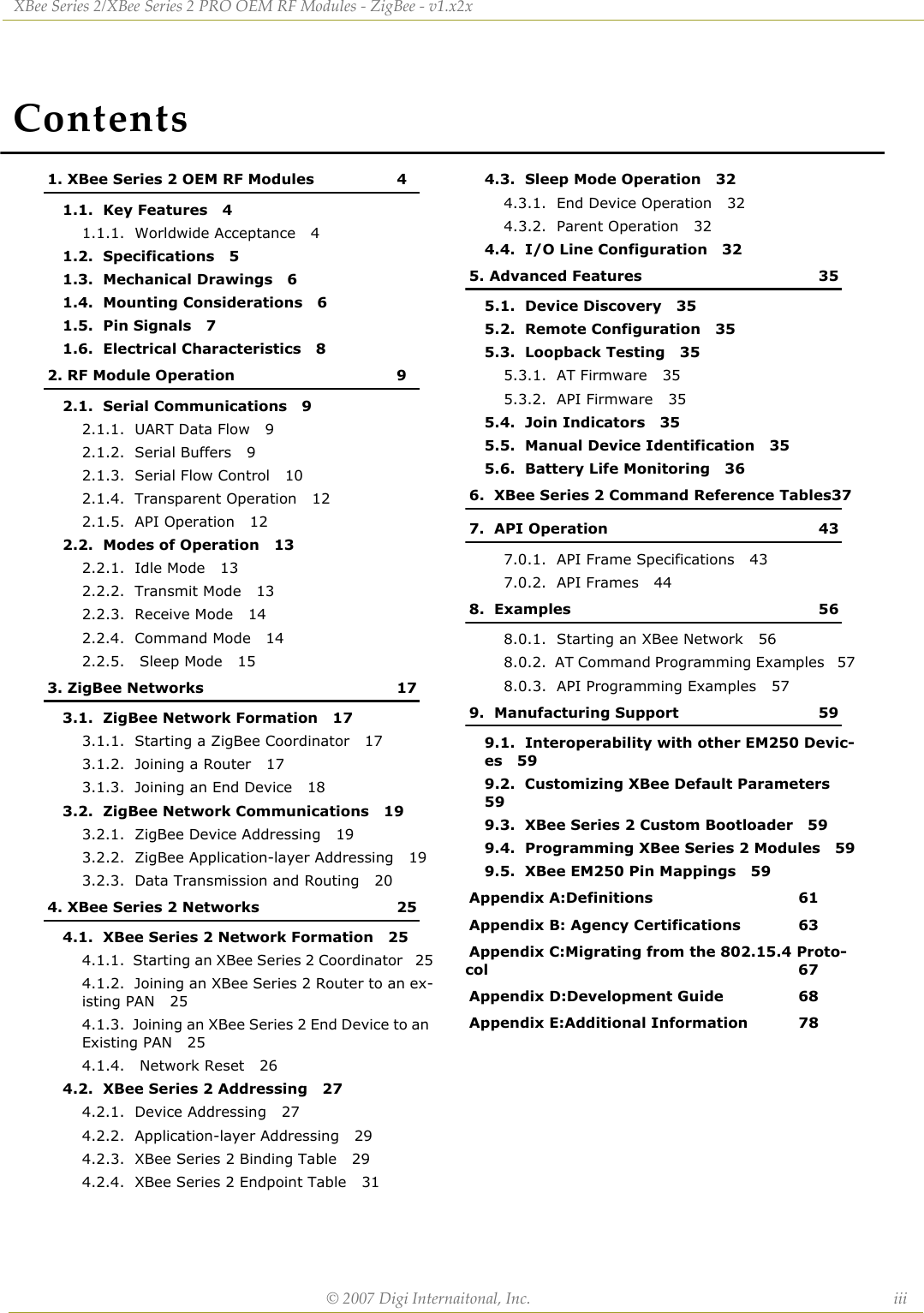
Contents
1.
USERS MANUAL
2.
Revised Used Manual
USERS MANUAL
Navigation menu
Upload a User Manual
Namespaces
Wiki Guide
HTML
PDF
Info
Views
User Manual
Discussion / Help
Navigation

![XBeeSeries2/Series2PROOEMRFModules‐ZigBee‐v1.x2x[2007.010.031]©2007DigiInternational,Inc. ii© 2007 Digi International, Inc. All rights reservedNopartofthecontentsofthismanualmaybetransmittedorreproducedinanyformorbyanymeanswithoutthewrittenpermissionofDigiInternational,Inc.ZigBee®isaregisteredtrademarkoftheZigBeeAlliance.XBee™Series2/XBee™Series2PROisatrademarkofDigiInternational,Inc.TechnicalSupport:Phone:(801)765‐9885LiveChat:www.digi.comE‐mail:support@digi.com](https://usermanual.wiki/Digi/XBEEPRO2.USERS-MANUAL/User-Guide-865868-Page-2.png)
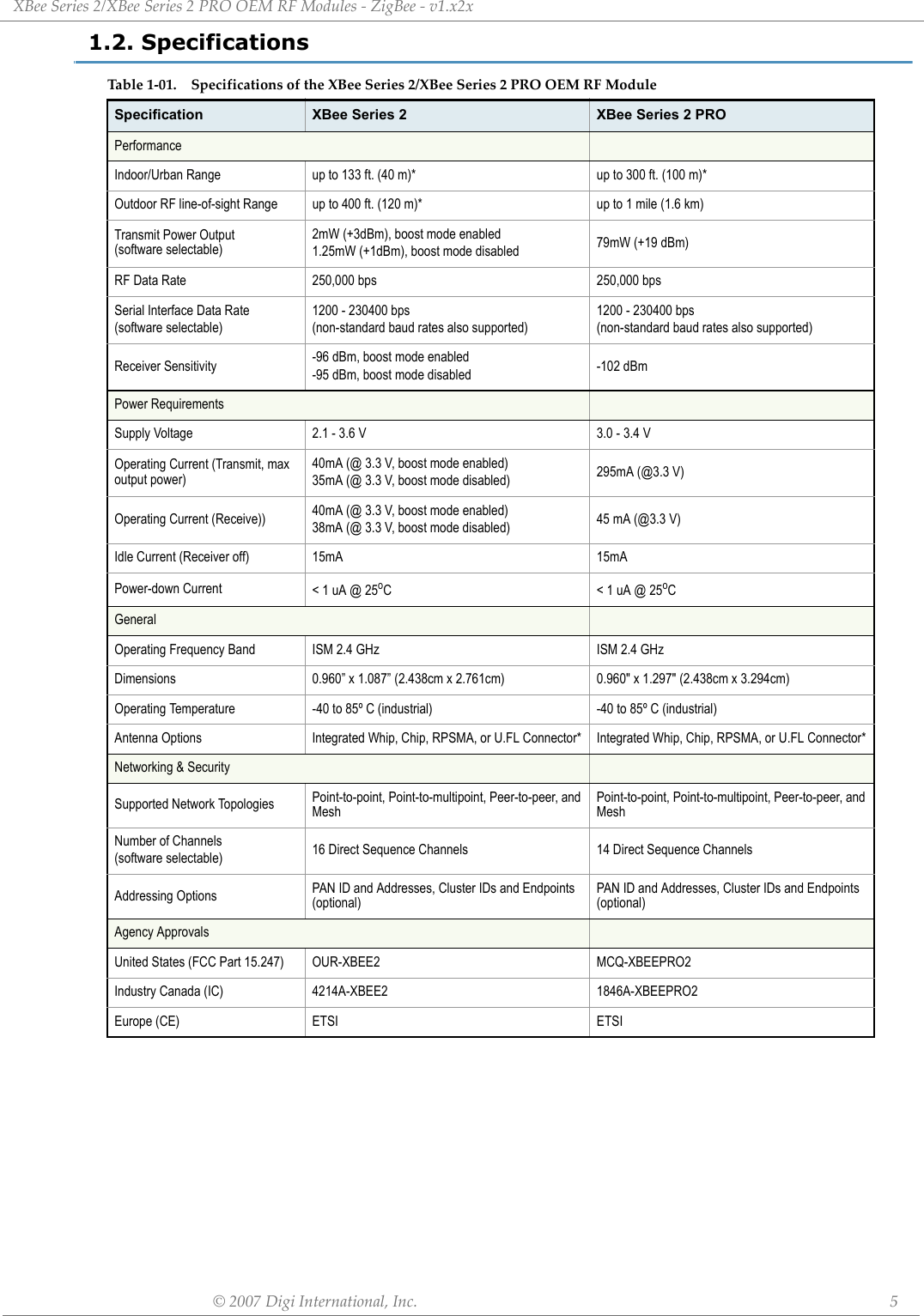
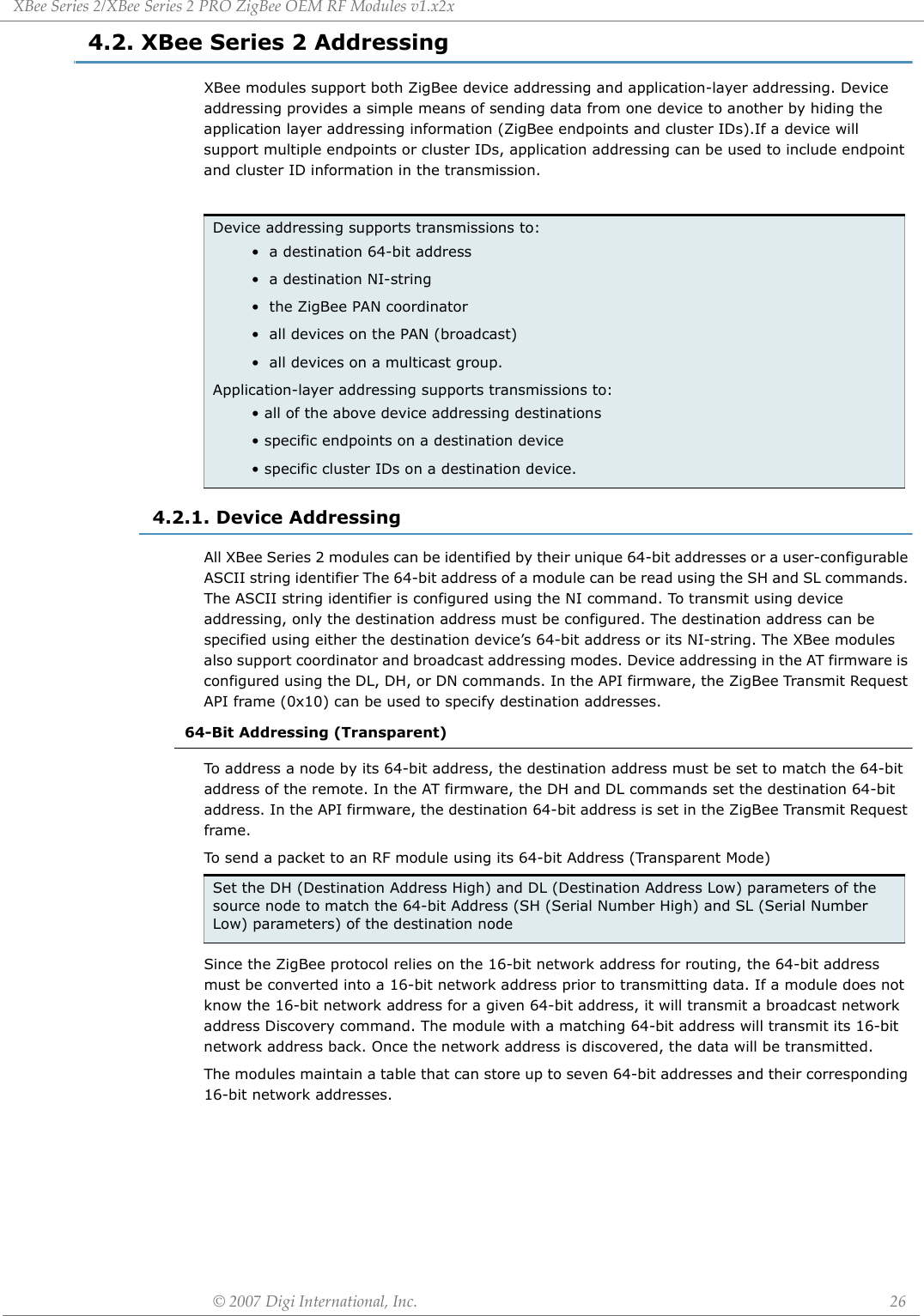
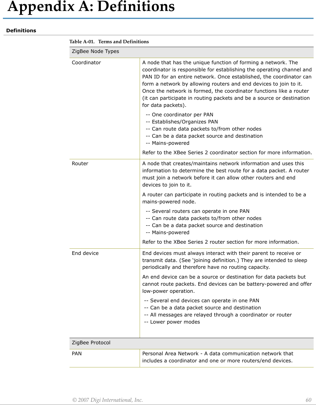
![©2007DigiInternational,Inc. 41.XBeeSeries2/XBeeSeries2PROOEMRFModulesThe XBee Series 2 PRO OEM RF Modules were engineered to operate within the ZigBee protocol and support the unique needs of low-cost, low-power wireless sensor networks. The modules require minimal power and provide reliable delivery of data between remote devices.The modules operate within the ISM 2.4 GHz frequency band.1.1. Key Features1.1.1. Worldwide AcceptanceFCC Approval (USA) Refer to Appendix A [p50] for FCC Requirements. Systems that contain XBee Series 2/XBee Series 2 PRO RF Modules inherit Digi Certifications.ISM (Industrial, Scientific & Medical) 2.4 GHz frequency bandManufactured under ISO 9001:2000 registered standardsXBee Series 2/XBee Series 2 PRO RF Modules are optimized for use in US, Canada, Australia, Israel and Europe (contact MaxStream for complete list of agency approvals).High Performance, Low Cost• Indoor/Urban: up to 300’ (100 m)• Outdoor line-of-sight: up to 1 mile (1.6 km)• Transmit Power Output: 100 mW (20 dBm) EIRP• Receiver Sensitivity: -102 dBmRF Data Rate: 250,000 bpsAdvanced Networking & SecurityRetries and AcknowledgementsDSSS (Direct Sequence Spread Spectrum)Each direct sequence channel has over 65,000 unique network addresses availablePoint-to-point, point-to-multipoint and peer-to-peer topologies supportedSelf-routing, self-healing and fault-tolerant mesh networkingLow PowerXBee Series 2 PRO• TX Current: 295 mA (@3.3 V)• RX Current: 45 mA (@3.3 V)• Power-down Current: < 1 µA @ 25oC Easy-to-UseNo configuration necessary for out-of box RF communicationsAT and API Command Modes for configuring module parametersSmall form factorExtensive command setFree X-CTU Software (Testing and configuration software)Free & Unlimited Technical Support](https://usermanual.wiki/Digi/XBEEPRO2.USERS-MANUAL/User-Guide-865868-Page-4.png)

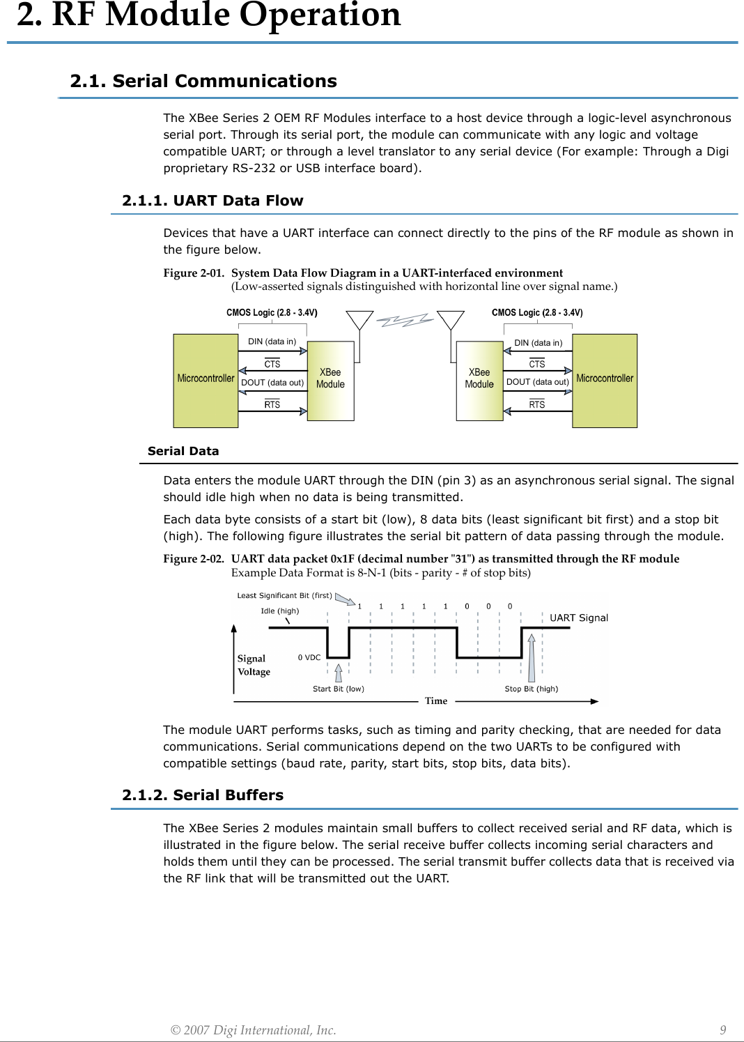
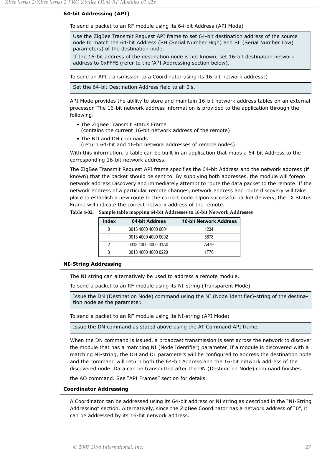
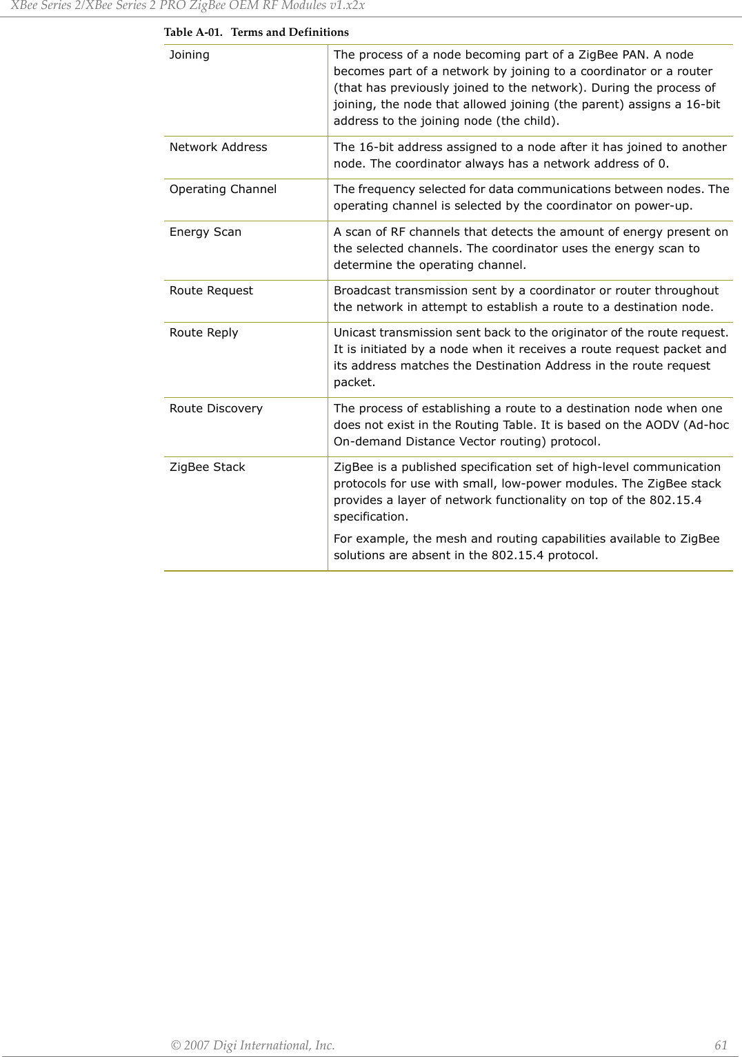
![XBeeSeries2/XBeeSeries2PROOEMRFModules‐ZigBee‐v1.x2x©2007DigiInternational,Inc. 71.5. Pin SignalsFigure1‐03. XBeeSeries2/XBeeSeries2PRORFModulePinNumber(topsidesshown‐shieldsonbottom)Design Notes:• Minimum connections: VCC, GND, DOUT & DIN• Minimum connections to support serial firmware upgrades: VCC, GND, DIN, DOUT, RTS & DTR• Signal Direction is specified with respect to the module• Module includes a 30k Ohm resistor attached to RESET• Several of the input pull-ups can be configured using the PR command• Unused pins should be left disconnectedTab le1‐02. PinAssignmentsfortheXBeeSeries2PROModules (Low‐assertedsignalsaredistinguishedwithahorizontallineabovesignalname.)Pin # Name Direction Description1 VCC - Power supply2 DOUT Output UART Data Out3 DIN / CONFIG Input UART Data In4 DIO12 Either Digital I/O 125RESET Input Module Reset (reset pulse must be at least 200 ns)6 PWM0 / RSSI / DIO10 Either PWM Output 0 / RX Signal Strength Indicator / Digital IO7 PWM / DIO11 Either Digital I/O 118 [reserved] - Do not connect9DTR / SLEEP_RQ/ DIO8 Either Pin Sleep Control Line or Digital IO 810 GND - Ground11 DIO4 Either Digital I/O 412 CTS / DIO7 Either Clear-to-Send Flow Control or Digital I/O 713 ON / SLEEP / DIO9 Output Module Status Indicator or Digital I/O 914 [reserved] - Do not connect15 Associate / DIO5 Either Associated Indicator, Digital I/O 516 RTS / DIO6 Either Request-to-Send Flow Control, Digital I/O 617 AD3 / DIO3 Either Analog Input 3 or Digital I/O 318 AD2 / DIO2 Either Analog Input 2 or Digital I/O 219 AD1 / DIO1 Either Analog Input 1 or Digital I/O 120 AD0 / DIO0 / ID Button Either Analog Input 0, Digital I/O 0, or Node Identification](https://usermanual.wiki/Digi/XBEEPRO2.USERS-MANUAL/User-Guide-865868-Page-7.png)

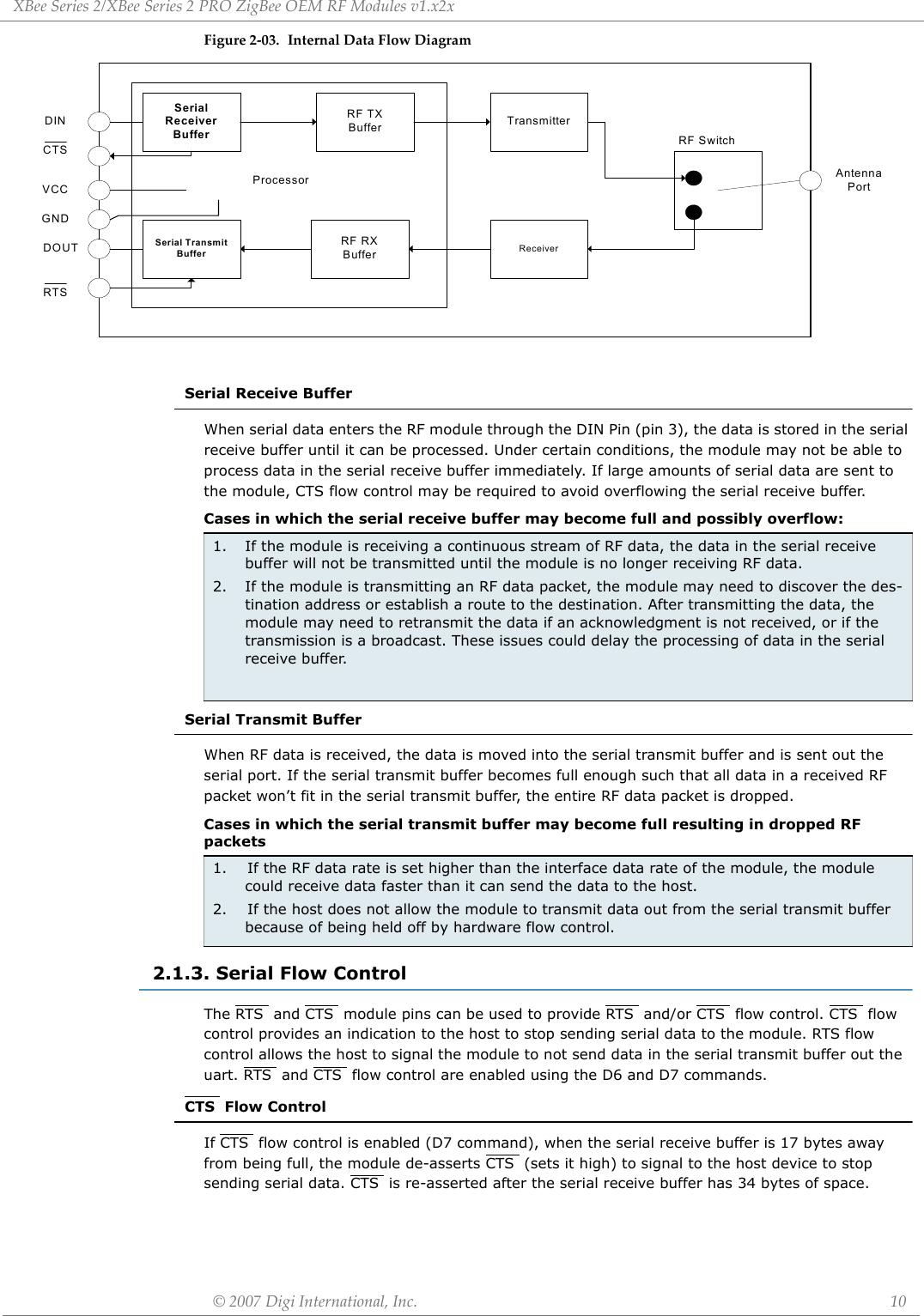
![XBeeSeries2/XBeeSeries2PROZigBeeOEMRFModulesv1.x2x©2007DigiInternational,Inc. 132.2.3. Receive ModeIf a valid RF packet is received, the data is transferred to the serial transmit buffer2.2.4. Command ModeTo modify or read RF Module parameters, the module must first enter into Command Mode - a state in which incoming serial characters are interpreted as commands. Refer to the API Mode section for an alternate means of configuring modules.AT Command ModeTo Enter AT Command Mode:Default AT Command Mode Sequence (for transition to Command Mode):• No characters sent for one second [GT (Guard Times) parameter = 0x3E8]• Input three plus characters (“+++”) within one second [CC (Command Sequence Character) parameter = 0x2B.]• No characters sent for one second [GT (Guard Times) parameter = 0x3E8]All of the parameter values in the sequence can be modified to reflect user preferences.NOTE: Failure to enter AT Command Mode is most commonly due to baud rate mismatch. Ensure the ‘Baud’ setting on the “PC Settings” tab matches the interface data rate of the RF module. By default, the BD parameter = 3 (9600 bps).To Send AT Commands:Figure2‐05.SyntaxforsendingATCommandsTo read a parameter value stored in the RF module’s register, omit the parameter field.The preceding example would change the RF module Destination Address (Low) to “0x1F”. To store the new value to non-volatile (long term) memory, subsequently send the WR (Write) command.For modified parameter values to persist in the module’s registry after a reset, changes must be saved to non-volatile memory using the WR (Write) Command. Otherwise, parameters are restored to previously saved values after the module is reset.System Response. When a command is sent to the module, the module will parse and execute the command. Upon successful execution of a command, the module returns an “OK” message. If execution of a command results in an error, the module returns an “ERROR” message.To Exit AT Command Mode:For an example of programming the RF module using AT Commands and descriptions of each configurable parameter, refer to the "Examples" and "XBee Series 2 Command Reference Tables" chapters.Send the 3-character command sequence “+++” and observe guard times before and after the command characters. [Refer to the “Default AT Command Mode Sequence” below.]Send AT commands and parameters using the syntax shown below.1. Send the ATCN (Exit Command Mode) command (followed by a carriage return). [OR]2. If no valid AT Commands are received within the time specified by CT (Command Mode Timeout) Command, the RF module automatically returns to Idle Mode.](https://usermanual.wiki/Digi/XBEEPRO2.USERS-MANUAL/User-Guide-865868-Page-13.png)

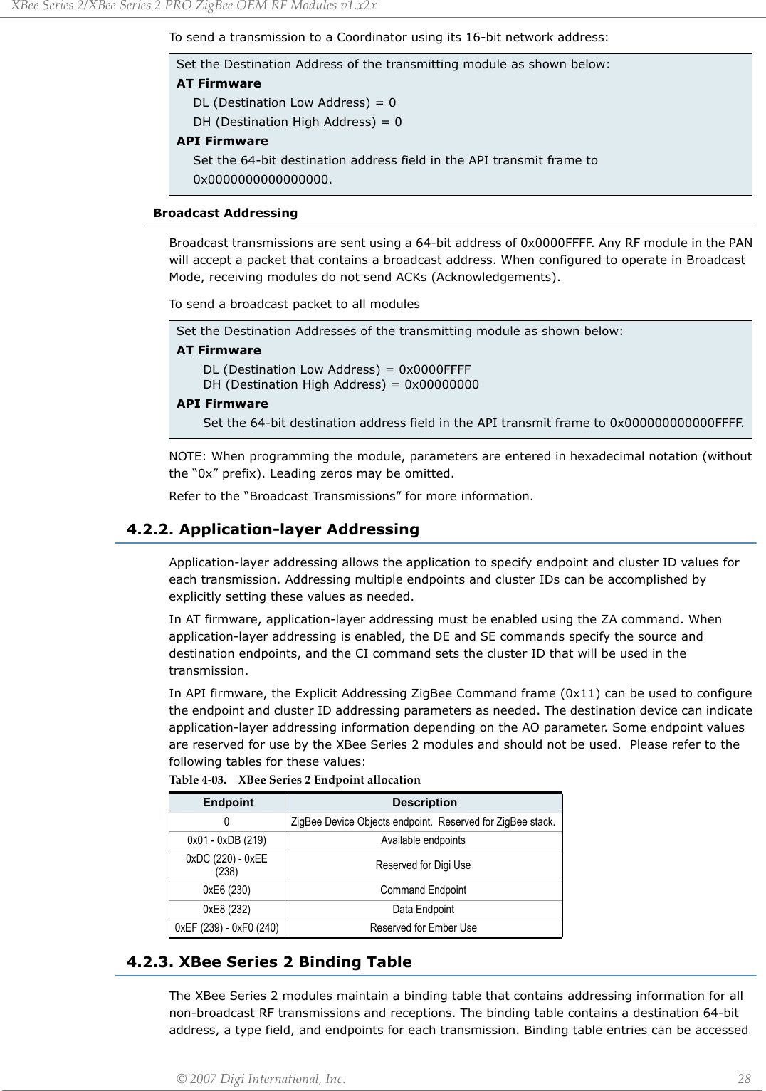
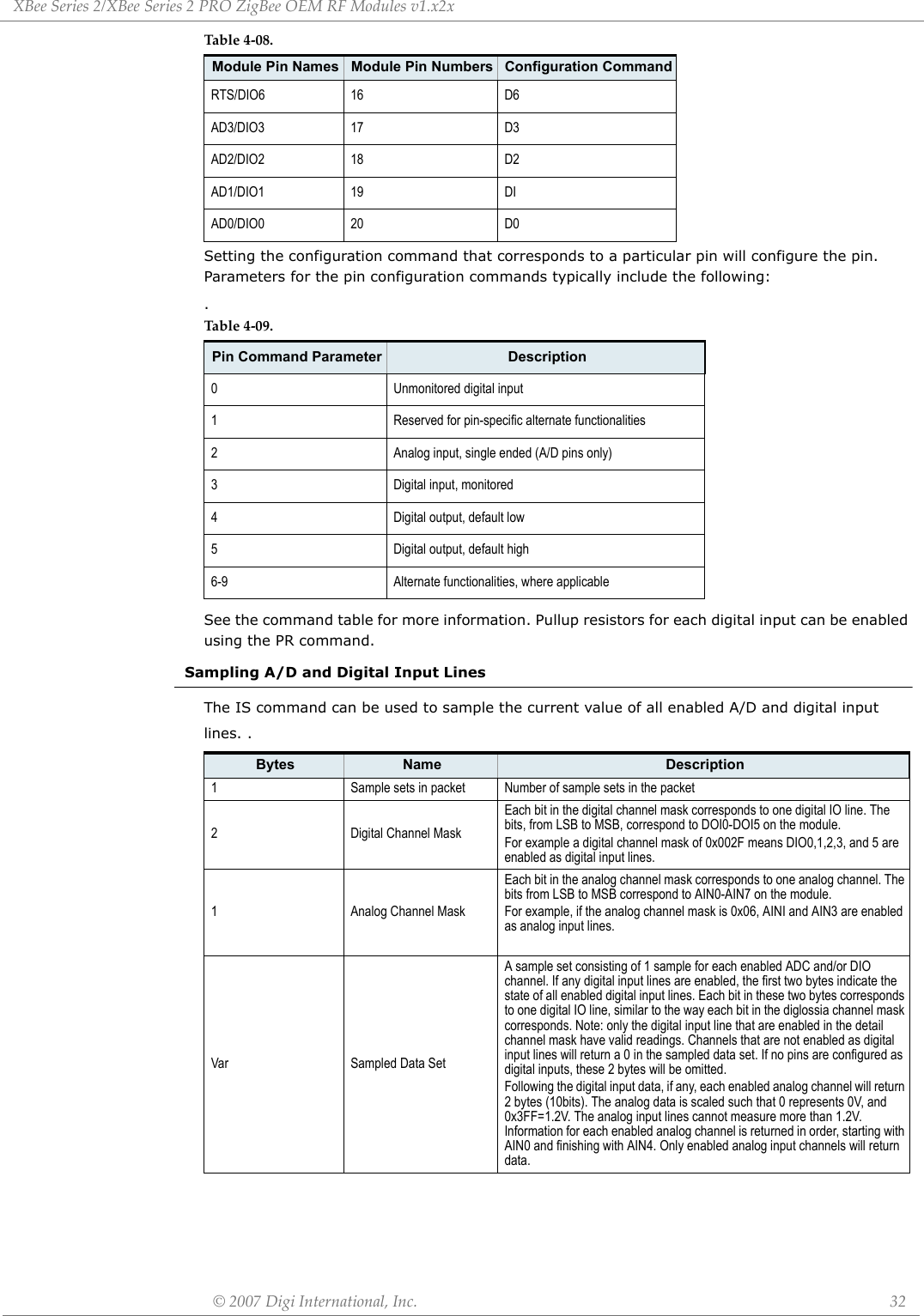
![XBeeSeries2/XBeeSeries2PROZigBeeOEMRFModulesv1.x2x©2007DigiInternational,Inc. 33The AT firmware returns a carriage return delimited list containing the above-listed fields. The API firmware returns an AT command response API frame with the IO data included in the command data portion of the packet.To convert the A/D reading to mV, do the following:AD(mV)= (ADIO reading/0x3FF)*1200mVThe reading in the sample frame represent voltage inputs of 1144.9 and 342.5mV for ADIO0 and ADIO1 respectively.Example Sample AT Response0x01\r [1 sample set]0x0C0C\r [Digital Inputs: DIO 2, 3, 10, 11 low]0x03\r [Analog Inputs: A/D 0, 1]0x0408\r [Digital input states: DIO 3, 10 high, DIO 2, 11 low]0x03D0\r [Analog input ADIO 0= 0x3D0]0x0124\r [Analog input ADIO 1=0x120]](https://usermanual.wiki/Digi/XBEEPRO2.USERS-MANUAL/User-Guide-865868-Page-33.png)

![©2007DigiInternational,Inc. 366.XBeeSeries2CommandReferenceTablesSpecialNodetypesthatsupportthecommand:C=Coordinator,R=Router,E=EndDeviceAddressingTab le6‐01. SpecialCommandsAT Command Name and Description Node Type1Parameter Range DefaultWRWrite. Write parameter values to non-volatile memory so that parameter modifications persist through subsequent resets. Note: Once WR is issued, no additional characters should be sent to the module until after the "OK\r" response is received.CRE -- --WB Write Binding Table: Writes the current binding table to non-volative memory. CRE -- --RE Restore Defaults. Restore module parameters to factory defaults. RE command does not reset the ID parameter. CRE -- --FRSoftware Reset. Reset module. Responds immediately with an “OK” then performs a reset ~2 seconds later. Use of the FR command will cause a network layer restart on the node if SC or ID were modified since the last reset.CRE -- --NRNetwork Reset. Reset network layer parameters on one or more modules within a PAN. Responds immediately with an “OK” then causes a network restart. All network configuration and routing information is consequently lost.If NR = 0: Resets network layer parameters on the node issuing the command. If NR = 1: Sends broadcast transmission to reset network layer parameters on all nodes in the PAN. CRE 0 - 1 --Table6‐02. AddressingCommands)AT Command Name and Description Node Type1Parameter Range DefaultDH2Destination Address High. Set/Get the upper 32 bits of the 64-bit destination address. When combined with DL, it defines the destination address used for transmission. 0x000000000000FFFF is the broadcast address for the PAN. DH is not supported in API Mode. 0x0000000000000000 is the Coordinator’s 16-bit network address.CRE 0 - 0xFFFFFFFF 0DL2Destination Address Low. Set/Get the lower 32 bits of the 64-bit destination address. When combined with DH, DL defines the destination address used for transmission. 0x000000000000FFFF is the broadcast address for the PAN. DL is not supported in API Mode. 0x0000000000000000 is the Coordinator’s 16-bit network address.CRE 0 - 0xFFFFFFFF 0xFFFF(Coordinator)0 (Router/End Device)MY 16-bit Network Address. Get the 16-bit network address of the module. CRE 0 - 0xFFFE [read-only] 0xFFFEMP 16-bit Parent Network Address. Get the 16-bit parent network address of the module. E 0 - 0xFFFE [read-only] 0xFFFESH Serial Number High. Read high 32 bits of the RF module's unique IEEE 64-bit address. 64-bit source address is always enabled. CRE 0 - 0xFFFFFFFF [read-only] factory-setSL Serial Number Low. Read low 32 bits of the RF module's unique IEEE 64-bit address. 64-bit source address is always enabled. CRE 0 - 0xFFFFFFFF [read-only] factory-setNINode Identifier. Stores a string identifier. The register only accepts printable ASCII data. In AT Command Mode, a string can not start with a space. A carriage return ends the command. Command will automatically end when maximum bytes for the string have been entered. This string is returned as part of the ND (Node Discover) command. This identifier is also used with the DN (Destination Node) command.CRE 20-Byte printable ASCII string --DD Device Type Identifier. Stores a device type value. This value can be used to differentiate multiple XBee-based products. CRE 0 - 0xFFFF [read-only] 0ZA2ZigBee Application Layer Addressing. Set/read the Zigbee application layer addressing enabled attribute. If enabled, data packets will use the SE, DE, and CI commands to address Zigbee application layer source and destination endpoints, and the cluster ID fields in all data transmissions. ZA is only supported in the AT firmware.CRE 0 - 1 0SE2Source Endpoint. Set/read the ZigBee application layer source endpoint value. If ZigBee application layer addressing is enabled (ZA command), this value will be used as the source endpoint for all data transmissions. SE is only supported in AT firmware.The default value 0xE8 (Data endpoint) is the Digi data endpoint CRE 1 - 0xEF 0xE8DE2Destination Endpoint. Set/read Zigbee application layer destination ID value. If ZigBee application layer addressing is enabled (ZA command), this value will be used as the destination endpoint all data transmissions. DE is only supported in AT firmware.The default value (0xE8) is the Digi data endpoint. CRE 0 - 0xEF 0xE8](https://usermanual.wiki/Digi/XBEEPRO2.USERS-MANUAL/User-Guide-865868-Page-36.png)
![XBeeSeries2/XBeeSeries2PROZigBeeOEMRFModulesv1.x2x©2007DigiInternational,Inc. 371.Nodetypesthatsupportthecommand:C=Coordinator,R=Router,E=EndDevice 2.CommandsupportedbymodulesusingATCommandfirmwareonlyNetworking & SecurityCI2Cluster Identifier. Set/read Zigbee application layer cluster ID value. If ZigBee application layer addressing is enabled (ZA command), this value will be used as the cluster ID for all data transmissions. CI is only supported in AT firmware.The default value0x11 (Transparent data cluster ID).CRE 0 - 0xFF 0x11 BI2Binding Table Index. Set/read the binding table index value. If this value is set to a valid binding table index, the addressing information at that index in the binding table will be used for all data transmissions. BI is only supported in AT firmwareCRE 0 - 0xFF 0xFFTable6‐03. NetworkingCommandsAT Command Name and Description Node Type1Parameter Range DefaultCHOperating Channel. Read the channel number used for transmitting and receiving between RF modules. Uses 802.15.4 channel numbers. A value of 0 means the device has not joined a PAN and is not operating on any channel.CRE 0, 0x0B-0x1A (XBee) 0IDPAN ID. Set/Get the PAN (Personal Area Network) ID. Coordinator - Set the preferred Pan ID. Set ID = 0xFFFF to auto-select. Router / End Device - Set the desired Pan ID. When the device searches for a Coordinator, it attempts to only join to a parent that has a matching Pan ID. Set ID = 0xFFFF to join a parent operating on any Pan ID.Changes to ID should be written to non-volatile memory using the WR command. CRE 0 - 0x3FFF, 0xFFFF 0x0234 (291d)BH Broadcast Hops. Set/Read the maximum number of hops for each broadcast data transmission. Setting this to 0 will use the maximum number of hops. CRE 0 - 0x0F --NT Node Discover Timeout. Set/Read the amount of time a node will spend discovering other nodes when ND or DN is issued. CRE 0 - 0xFC [x 100 msec] 0x3C (60d)NDNode Discover. Discovers and reports all RF modules found. The following information is reported for each module discovered. MY<CR> SH<CR> SL<CR> NI<CR> (Variable length) PARENT_NETWORK ADDRESS (2 Bytes)<CR> DEVICE_TYPE<CR> (1 Byte: 0=Coord, 1=Router, 2=End Device) STATUS<CR> (1 Byte: Reserved) PROFILE_ID<CR> (2 Bytes) MANUFACTURER_ID<CR> (2 Bytes) <CR> After (NT * 100) milliseconds, the command ends by returning a <CR>. ND also accepts a Node Identifier (NI) as a parameter (optional). In this case, only a module that matches the supplied identifier will respond.If ND is sent through the API, each response is returned as a separate AT_CMD_Response packet. The data consists of the above listed bytes without the carriage return delimiters. The NI string will end in a "0x00" null character. The radius of the ND command is set by the BH command.CRE optional 20-Byte NI or MY value --DNDestination Node. Resolves an NI (Node Identifier) string to a physical address (case-sensitive). The following events occur after the destination node is discovered:<AT Firmware> 1. DL & DH are set to the extended (64-bit) address of the module with the matching NI (Node Identifier) string. 2. OK (or ERROR)\r is returned. 3. Command Mode is exited to allow immediate communication<API Firmware> 1. The 16-bit network and 64-bit extended addresses are returned in an API Command Response frame.If there is no response from a module within (NT * 100) milliseconds or a parameter is not specified (left blank), the command is terminated and an “ERROR” message is returned. In the case of an ERROR, Command Mode is not exited. The radius of the DN command is set by the BH command.CRE up to 20-Byte printable ASCII string --JN Join Notification. Set/read the join notification value. If enabled, the device will send a transmission after joining a PAN, identifying itself to the coordinator. RE0 - Join notification disabled1 - Send notification only to coordinator after joining PAN1Table6‐02. AddressingCommands)AT Command Name and Description Node Type1Parameter Range Default](https://usermanual.wiki/Digi/XBEEPRO2.USERS-MANUAL/User-Guide-865868-Page-37.png)
![XBeeSeries2/XBeeSeries2PROZigBeeOEMRFModulesv1.x2x©2007DigiInternational,Inc. 38RF Interfacing 1.Nodetypesthatsupportthecommand:C=Coordinator,R=Router,E=EndDeviceSerial Interfacing (I/O)SCScan Channels. Set/Read the list of channels to scan.Coordinator - Bit field list of channels to choose from prior to starting network.Router/End Device - Bit field list of channels that will be scanned to find a Coordinator/Router to join.Changes to SC should be written using WR command. Bit (Channel): 0 (0x0B) 4 (0x0F) 8 (0x13) 12 (0x17) 1 (0x0C) 5 (0x10) 9 (0x14) 13 (0x18) 2 (0x0D) 6 (0x11) 10 (0x15) 14 (0x19) 3 (0x0E) 7 (0x12) 11 (0x16) 15 (0x1A)CRE 1 - 0xFFFF[bitfield] 0x1FFE SDScan Duration. Set/Read the scan duration exponent. Changes to SD should be written using WR command. Coordinator - Duration of the Active and Energy Scans (on each channel) that are used to determine an acceptable channel and Pan ID for the Coordinator to startup on. Router / End Device - Duration of Active Scan (on each channel) used to locate an available Coordinator / Router to join during Association.Scan Time is measured as:(# Channels to Scan) * (2 ^ SD) * 15.36ms - The number of channels to scan is determined by the SC parameter. The XBee can scan up to 16 channels (SC = 0xFFFF).Sample Scan Duration times (13 channel scan): If SD = 0, time = 0.200 sec SD = 2, time = 0.799 sec SD = 4, time = 3.190 sec SD = 6, time = 12.780 secCRE 0 - 7 [exponent] 3NJNode Join Time. Set/Read the time that a Coordinator/Router allows nodes to join. This value can be changed at run time without requiring a Coordinator or Router to restart. The time starts once the Coordinator or Router has started. The timer is reset on power-cycle or when NJ changes.CR 0 – 0x40, 0xFF [x 1 sec] 0xFF (always allows joining)ARAggregate Routing Notification. Set/read time between consecutive aggregate route broadcast messages. If used, AR should be set on only one device to enable many-to-one routing to the device. Setting AR to 0 only sends one broadcastCR 0 - 0xFF 0xFFAIAssociation Indication. Read information regarding last node join request:0x00 - Successful completion - Coordinator started or Router/End Device found and joined with a parent. 0x21 - Scan found no PANs 0x22 - Scan found no valid PANs based on current SC and ID settings 0x23 - Valid Coordinator or Routers found, but they are not allowing joining (NJ expired) 0x27 - Node Joining attempt failed 0x2A - Coordinator Start attempt failed‘ 0xFF - Scanning for a ParentCRE 0 - 0xFF [read-only] --Table6‐04. RFInterfacingCommandsAT Command Name and Description Node Type1Parameter Range DefaultPL Power Level. Select/Read the power level at which the RF module transmits conducted power. CRE0 - 4 (XBee ) 0 = -10 / 10 dBm 1 = -6 / 12 dBm 2 = -4 / 14 dBm 3 = -2 / 16 dBm 4 = 0 / 18 dBm4PM Power Mode. Set/read the power mode of the device. Enabling boost mode will improve the receive sensitivity by 1dB and increase the transmit power by 2dB CRE0-1, 0= -Boost mode disabled, 1= Boost mode enabled. 1Table6‐05. SerialInterfacingCommandsAT Command Name and Description Node Type1Parameter Range DefaultAP2API Enable. Enable API Mode. The AP parameter is only applicable when using modules that contain the following firmware versions:1.1xx (coordinator), 1.3xx (router/end device)CRE1 - 2 1 = API-enabled 2 = API-enabled (w/escaped control characters)1Table6‐03. NetworkingCommandsAT Command Name and Description Node Type1Parameter Range Default](https://usermanual.wiki/Digi/XBEEPRO2.USERS-MANUAL/User-Guide-865868-Page-38.png)
![XBeeSeries2/XBeeSeries2PROZigBeeOEMRFModulesv1.x2x©2007DigiInternational,Inc. 391.Nodetypesthatsupportthecommand:C=Coordinator,R=Router,E=EndDevice 2.CommandsupportedbymodulesusingAPIfirmwareonlyI/O CommandsAO2API Options. Configure options for API. Current options select the type of receive API frame to send out the Uart for received RF data packets. CRE0 - Default receive API indicators enabled1 - Explicit Rx data indicator API frame enabled (0x91)0BDInterface Data Rate. Set/Read the serial interface data rate for communication between the module serial port and host.Any value above 0x07 will be interpreted as an actual baud rate. When a value above 0x07 is sent, the closest interface data rate represented by the number is stored in the BD register.CRE0 - 7 (standard baud rates) 0 = 1200 bps 1 = 2400 2 = 4800 3 = 9600 4 = 19200 5 = 38400 6 = 57600 7 = 115200 0x80 - 0x38400 (non-standard rates)3ROPacketization Timeout. Set/Read number of character times of inter-character silence required before packetization. Set (RO=0) to transmit characters as they arrive instead of buffering them into one RF packet.CRE 0 - 0xFF [x character times] 3D7 DIO7 Configuration. Select/Read options for the DIO7 line of the RF module. CRE0 = Disabled 1 = CTS Flow Control3 = Digital input4 = Digital output, low5 = Digital output, high6 = RS-485 transmit enable (low enable)7 = RS-485 transmit enable (high enable)1D6 DIO6 Configuration. Configure options for the DIO6 line of the RF module. CRE 0 - Disabled1 - RTS Flow Control 0D5 DIO5 Configuration. Configure options for the DIO5 line of the RF module. CRE 0 = Disabled 1 = Associated indication LED3 = Digital input4 = Digital output, default low5 = Digital output, default high1Table6‐06. I/OCommandsAT Command Name and Description Node Type1Parameter Range DefaultP0 PWM0 Configuration. Select/Read function for PWM0. CRE0 = Disabled 1 = RSSI PWM3 - Digital input, monitored4 - Digital output, default low5 - Digital output, default high1P1 DIO11 Configuration. Configure options for the DIO11 line of the RF module. CRE0 - Unmonitored digital input3- Digital input, monitored4- Digital output, default low5- Digital output, default high0Table6‐05. SerialInterfacingCommandsAT Command Name and Description Node Type1Parameter Range Default](https://usermanual.wiki/Digi/XBEEPRO2.USERS-MANUAL/User-Guide-865868-Page-39.png)
![XBeeSeries2/XBeeSeries2PROZigBeeOEMRFModulesv1.x2x©2007DigiInternational,Inc. 40P2 DIO12 Configuration. Configure options for the DIO12 line of the RF module. CRE0 - Unmonitored digital input3- Digital input, monitored4- Digital output, default low5- Digital output, default high0RP RSSI PWM Timer. Time RSSI signal will be output after last transmission. When RP = 0xFF, output will always be on. CRE 0 - 0xFF [x 100 ms] 0x28 (40d)IS Force Sample Forces a read of all enabled digital and analog input lines. CRE -- --D0 AD0/DIO0 Configuration. Select/Read function for AD0/DIO0. CRE0-5 0 – Disabled 1 - Node identification button enabled 2 - Analog input, single ended3 – Digital input4 – Digital output, low5 – Digital output, high1 (RE), 0 (C)D1 AD1/DIO1 Configuration. Select/Read function for AD1/DIO1. CRE 0, 2-50 – Disabled 2 - Analog input, single ended 3 – Digital input4 – Digital output, low5 – Digital output, high0D2 AD2/DIO2 Configuration. Select/Read function for AD2/DIO2. CRE0, 2-50 – Disabled2 - Analog input, single ended 3 – Digital input4 – Digital output, low5 – Digital output, high0D3 AD3/DIO3 Configuration. Select/Read function for AD3/DIO3. CRE0, 2-50 – Disabled2 - Analog input, single ended3 – Digital input4 – Digital output, low5 – Digital output, high0D4 DIO4 Configuration. Select/Read function for DIO4. CRE 0, 3-50 – Disabled3 – Digital input4 – Digital output, low5 – Digital output, high0PRSet/read the bit field that configures the internal pull-up resistor status for the I/O lines. "1" specifies the pull-up resistor is enabled. "0" specifies no pullup.Bits:"0 - DIO4 (Pin 11)1 - AD3 / DIO3 (Pin 17)2 - AD2 / DIO2 (Pin 18)3 - AD1 / DIO1 (Pin 19)4 - AD0 / DIO0 (Pin 20)5 - RTS / DIO6 (Pin 16)6 - DTR / Sleep Request / DIO8 (Pin 9)7 - DIN / Config (Pin 3)8 - Associate / DIO5 (Pin 15)9 - On/Sleep / DIO9 (Pin 13)10 - DIO12 (Pin 4)11 - PWM0 / RSSI / DIO10 (Pin 6)12 - PWM1 / DIO11 (Pin 7)CRE 0 - 0x1FFF 0 - 0x1FFFTable6‐06. I/OCommandsAT Command Name and Description Node Type1Parameter Range Default](https://usermanual.wiki/Digi/XBEEPRO2.USERS-MANUAL/User-Guide-865868-Page-40.png)
![XBeeSeries2/XBeeSeries2PROZigBeeOEMRFModulesv1.x2x©2007DigiInternational,Inc. 41Diagnostics1.Nodetypesthatsupportthecommand:C=Coordinator,R=Router,E=EndDeviceAT Command Options1.Nodetypesthatsupportthecommand:C=Coordinator,R=Router,E=EndDevice 2.CommandsupportedbymodulesusingATCommandfirmwareonlySleep CommandsTable6‐07. DiagnosticsCommandsAT Command Name and Description Node Type1Parameter Range DefaultVR Firmware Version. Read firmware version of the module. CRE 0 - 0xFFFF [read-only] Factory-setHV Hardware Version. Read hardware version of the module. CRE 0 - 0xFFFF [read-only] Factory-set%VSupply Voltage. Reads the voltage on the Vcc pin. To convert the reading to a mV reading, divide the read value by 1023 and multiply by 1200. A %V reading of 0x8FE (2302 decimal) represents 2700mV or 2.70V.CRE - -Table6‐08. ATCommandOptionsCommandsAT Command Name and Description Node Type1Parameter Range DefaultCT2Command Mode Timeout. Set/Read the period of inactivity (no valid commands received) after which the RF module automatically exits AT Command Mode and returns to Idle Mode.CRE 2 - 0x028F [x 100 ms] 0x64 (100d)CN2Exit Command Mode. Explicitly exit the module from AT Command Mode. CRE -- --GT2Guard Times. Set required period of silence before and after the Command Sequence Characters of the AT Command Mode Sequence (GT + CC + GT). The period of silence is used to prevent inadvertent entrance into AT Command Mode.CRE 1 - 0x0CE4 [x 1 ms] (max of 3.3 decimal sec)0x3E8 (1000d)CC2Command Sequence Character. Set/Read the ASCII character value to be used between Guard Times of the AT Command Mode Sequence (GT + CC + GT). The AT Command Mode Sequence enters the RF module into AT Command Mode.CC command is only applicable when using modules that contain the following “AT Command” firmware versions: 8.0xx (Coordinator), 8.2xx (Router), 8.4xx (End Device)CRE 0 - 0xFF 0x2B (‘+’ ASCII)Table6‐09. SleepCommandsAT Command Name and Description Node Type1Parameter Range DefaultSM Sleep Mode Sets the sleep mode on the RF module RE0-Sleep disabled1-Pin sleep enabled4-Cyclic sleep enabledNote: When SM=0, the device operates as a router. When SM changes to a non-zero value, the router leaves the network and rejoins as an end device. Only end devices can sleep0SNNumber of Sleep Periods. Sets the number of sleep periods to not assert the On/Sleep pin on wakeup if no RF data is waiting for the end device. This command allows a host application to sleep for an extended time if no RF data is presentRE 1 - 0xFFFF 1SPSleep Period. This value determines how long the end device will sleep at a time, up to 28 seconds. (The sleep time can effectively be extended past 28 seconds using the SN command.) On the parent, this value determines how long the parent will buffer a message for the sleeping end device. It should be set at least equal to the longest SP time of any child end device.CRE0x20 - 0xAF0 x 10ms (Quarter second resolution)0x20STTime Before Sleep Sets the time before sleep timer on an end device.The timer is reset each time serial or RF data is received. Once the timer expires, an end device may enter low power operation. Applicable for cyclic sleep end devices only. RE 1 - 0xFFFE (x 1ms) 0x1388 (5 seconds)](https://usermanual.wiki/Digi/XBEEPRO2.USERS-MANUAL/User-Guide-865868-Page-41.png)
![XBeeSeries2/XBeeSeries2PROZigBeeOEMRFModulesv1.x2x©2007DigiInternational,Inc. 45Figure7‐05. AdvancedModemStatusFrames:DoNotUse!0x7E API-specific Structure 1 ByteMSB LSB0x8C cmdDataStatus ID1Start deliminator Length Frame Data ChecksumAPI Identifier Identifier specific data[Bind Table Index] + [Bind Type]Bind Type 1 – Unicast BindingBind Type 2 – Aggregation BindingBind Type 3 – Multicast Binding](https://usermanual.wiki/Digi/XBEEPRO2.USERS-MANUAL/User-Guide-865868-Page-45.png)
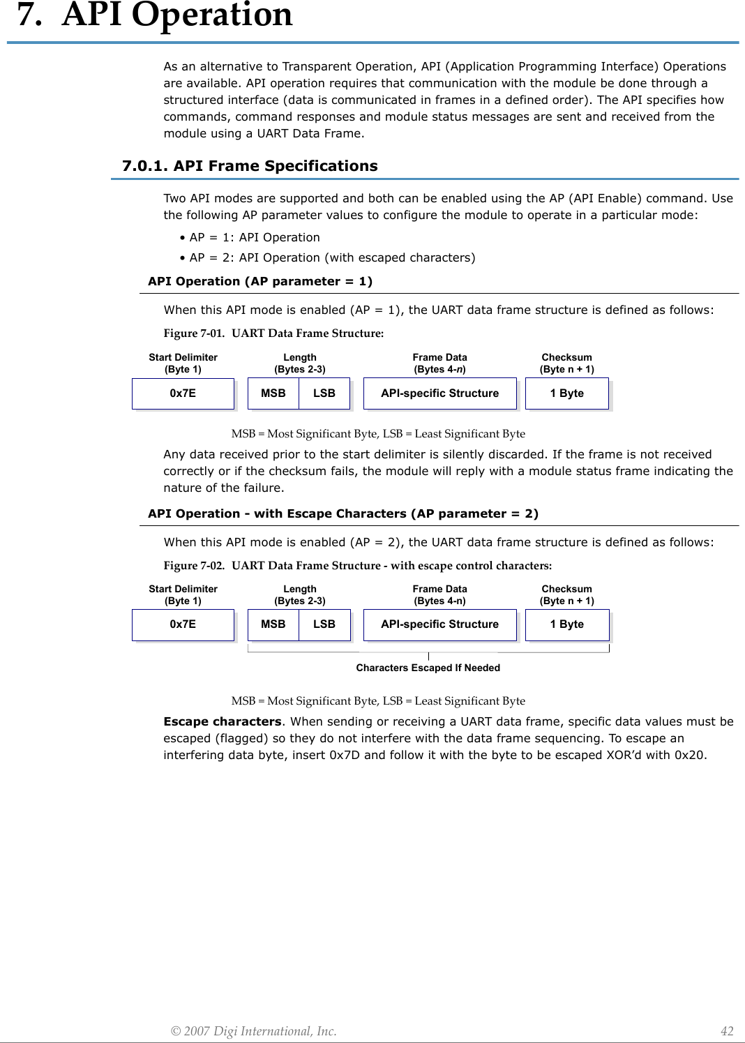
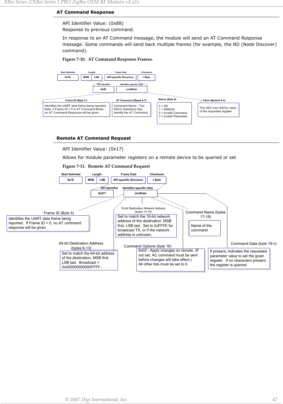
![XBeeSeries2/XBeeSeries2PROZigBeeOEMRFModulesv1.x2x©2007DigiInternational,Inc. 46AT CommandAPI Identifier Value: (0x08) Allows for module parameter registers to be queried or set.Figure7‐6. ATCommandFramesFigure7‐7. Example:APIframeswhenreadingtheNJparametervalueofthemodule.Figure7‐8. Example:APIframeswhenmodifyingtheNJparametervalueofthemodule.A string parameter used with the NI (Node Identifier), ND (Node Discover) and DH (Destination Address High) command is terminated with a 0x00 character.AT Command - Queue Parameter ValueAPI Identifier Value: (0x09) This API type allows module parameters to be queried or set. In contrast to the “AT Command” API type, new parameter values are queued and not applied until either the “AT Command” (0x08) API type or the AC (Apply Changes) command is issued. Register queries (reading parameter values) are returned immediately.Figure7‐9. ATCommandFrames (Notethatframesareidenticaltothe“ATCommand”APItypeexceptfortheAPIidentifier.)cmdData0x08Length ChecksumStart Delimiter Frame DataIdentifier-specific DataAPI IdentifierMSB LSB0x7E 1 ByteAPI-specific StructureFrame ID (Byte 5)Identifies the UART data frame for the host to correlate with a subsequent ACK (acknowledgement).If set to ‘0’, no response is sent.AT Command (Bytes 6-7)Command Name - Two ASCII characters that identify the AT Command.Parameter Value (Byte(s) 8-n)If present, indicates the requested parameter value to set the given register.If no characters present, register is queried.*Length[Bytes]=APIIdentifier+FrameID+ATCommand**“R”valuewasarbitrarilyselected.Checksum0x0DByte 8AT CommandBytes 6-7Frame ID**0x52 (R)Byte 50x4E (N) 0x4A (J)API Identifier0x08Byte 4Start DelimiterByte 10x7ELength*Bytes 2-30x00 0x04*Length[Bytes]=APIIdentifier+FrameID+ATCommand+ParameterValue**“M”valuewasarbitrarilyselected.Checksum0xD2Byte 9AT CommandBytes 6-70x4E (N) 0x4A (J)Parameter Value0x40Bytes 8Frame ID**0x4D (M)Byte 5Length*Bytes 2-30x00 0x05API Identifier0x08Byte 4Start DelimiterByte 10x7EcmdData0x09Length ChecksumStart Delimiter Frame DataIdentifier-specific DataAPI IdentifierMSB LSB0x7E 1 ByteAPI-specific StructureFrame ID (Byte 5)Identifies the UART data frame for the host to correlate with a subsequent ACK (acknowledgement).If set to ‘0’, no response is sent.AT Command (Bytes 6-7)Command Name - Two ASCII characters that identify the AT Command.Parameter Value (Byte(s) 8-n)If present, indicates the requested parameter value to set the given register.If no characters present, register is queried.](https://usermanual.wiki/Digi/XBEEPRO2.USERS-MANUAL/User-Guide-865868-Page-46.png)
![XBeeSeries2/XBeeSeries2PROZigBeeOEMRFModulesv1.x2x©2007DigiInternational,Inc. 568.0.2. AT Command Programming ExamplesSetupSample Configuration: Modify RF Module Destination AddressSample Configuration: Restore RF Module Defaults8.0.3. API Programming ExamplesAPI Configuration Using the X-CTUThe programming examples in this section require the installation of Digi's X-CTU Software and a serial connection to a PC. (Digi stocks RS-232 and USB boards to facilitate interfacing with a PC.)1. Install Digi's X-CTU Software to a PC by double-clicking the "setup_X-CTU.exe" file. 2. Mount the RF module to an interface board, then connect the module assembly to a PC.3. Launch the X-CTU Software and select the 'PC Settings' tab. Verify the baud and parity set-tings of the Com Port match those of the RF module.NOTE: Failure to enter AT Command Mode is most commonly due to baud rate mismatch. Ensure the ‘Baud’ setting on the ‘PC Settings’ tab matches the interface data rate of the RF mod-ule. By default, the BD parameter = 3 (which corresponds to 9600 bps).Example: Utilize the X-CTU “Terminal” tab to change the RF module's DL (Destination Address Low) parameter and save the new address to non-volatile memory.After establishing a serial connection between the RF module and a PC [refer to the 'Setup' sec-tion above], select the “Terminal” tab of the X-CTU Software and enter the following command lines (‘CR’ stands for carriage return):Method 1 (One line per command)Send AT Command +++ ATDL <Enter> ATDL1A0D <Enter> ATWR <Enter> ATCN <Enter>System Response OK <CR> (Enter into Command Mode) {current value} <CR> (Read Destination Address Low) OK <CR> (Modify Destination Address Low) OK <CR> (Write to non-volatile memory) OK <CR> (Exit Command Mode)Method 2 (Multiple commands on one line)Send AT Command +++ ATDL <Enter> ATDL1A0D,WR,CN <Enter>System Response OK <CR> (Enter into Command Mode) {current value} <CR> (Read Destination Address Low) OK<CR> OK<CR> OK<CR>Example: Utilize the X-CTU “Modem Configuration” tab to restore default parameter values.After establishing a connection between the module and a PC [refer to the 'Setup' section above], select the “Modem Configuration” tab of the X-CTU Software.1. Select the 'Read' button.2. Select the 'Restore' button.The programming examples in this section require the installation of Digi's X-CTU soware and a serial connection to a PC. See "Setup" example in the AT Command Programming Examples in Section 8.0.2.1. Launch the X-CTU Software and select the 'PC Settings' tab. Verify the baud and parity set-tings of the Com Port match those of the RF module.2. To communicate with a module that has API firmware, check the "Enable API" box. 3. If escaping is enabled (AP=2, non-default setting), select the "Use escape characters" box to enable escaping.4. Select the 'Modem Configuration' tab.5. The 'Read', 'Write', and 'Restore' buttons can be used to read module parameters, write new settings, or restore defaults.Refertothe‘X‐CTU’sec‐tionoftheDevelop‐mentGuide[AppendixB]formoreinformationregardingtheX‐CTUconfigurationsoftware.](https://usermanual.wiki/Digi/XBEEPRO2.USERS-MANUAL/User-Guide-865868-Page-56.png)
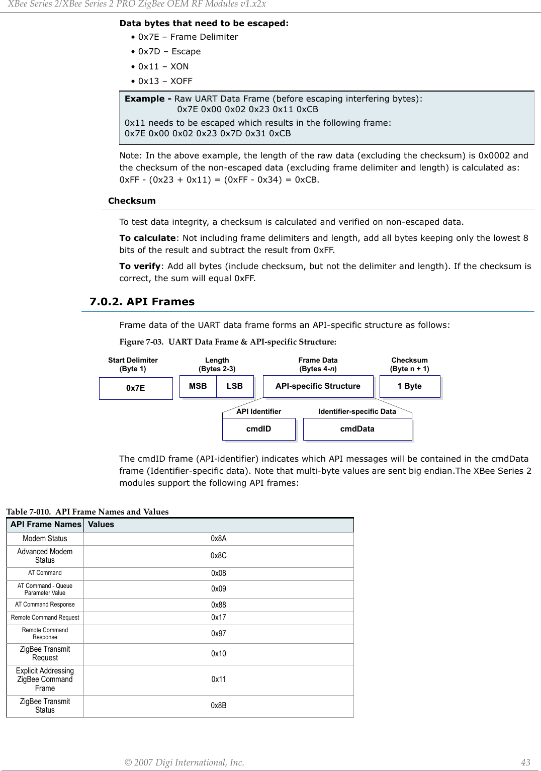
![XBeeSeries2/XBeeSeries2PROZigBeeOEMRFModulesv1.x2x©2007DigiInternational,Inc. 57Constructing API FramesExample: Create an API AT command frame to configure an XBee to allow joining (set NJ to 0xFF). The frame should look like: 0x7E 0x00 0x05 0x08 0x01 0x4E 0x4A 0xFF 5FWhere 0x0005 = length 0x08 = AT Command API frame type 0x01 = Frame ID (set to non-zero value) 0x4E4A = AT Command ('NJ') 0xFF = value to set command to 0x5F = ChecksumThe checksum is calculated as [0xFF - (0x08 + 0x01 + 0x4E + 0x4A + 0xFF)]Example: Send a transmission to a module with destination address 0x0013A200 40014011, payload "TxData1B". If escaping is disabled, (AP=1), the frame should look like: 0x7E 0x00 0x16 0x10 0x01 0x00 0x13 0xA2 0x00 0x40 0x0A 0x01 0x27 0xFF 0xFE 0x00 0x00 0x54 0x78 0x44 0x61 0x74 0x61 0x30 0x41 0x13Where 0x16 = length (22 bytes excluding checksum) 0x10 = ZigBee Transmit Request API frame type 0x01 = Frame ID (set to non-zero value) 0x0013A200400A0127 = 64-bit Destination Address 0xFFFE = 16-bit Destination Address 0x00 = Broadcast radius 0x00 = Options 0x5478446174613041 = Data payload ("TxData0A") 0x64 = ChecksumIf escaping is enabled (AP=2), the frame should look like: 0x7E 0x00 0x16 0x10 0x01 0x00 0x7D 0x33 0xA2 0x00 0x40 0x0A 0x01 0x27 0xFF 0xFE 0x00 0x00 0x54 0x78 0x44 0x61 0x74 0x61 0x30 0x41 0x7D 0x33The checksum is calculated (on all non-escaped bytes) as [0xFF - (sum of all bytes from API frame type through data payload)]. Example: Send a transmission to the coordinator without specifying the coordinator's 64-bit address. The API transmit request frame should look like:0x7E 0x00 0x16 0x10 0x01 0x00 0x00 0x00 0x00 0x00 0x00 0x00 0x00 0xFF 0xFE 0x00 0x00 0x54 0x78 032 0x43 0x6F 0x6F 0x72 0x64 0xFCWhere 0x16 = length (22 bytes excluding checksum) 0x10 = ZigBee Transmit Request API frame type 0x01 = Frame ID (set to non-zero value) 0x0000000000000000 = Coordinator's address (can be replaced with coordinator's actual 64-bit address if known 0xFFFE = 16-bit Destination Address 0x00 = Broadcast radius 0x00 = Options 0x547832436F6F7264 = Data payload ("Tx2Coord") 0xFC = Checksum](https://usermanual.wiki/Digi/XBEEPRO2.USERS-MANUAL/User-Guide-865868-Page-57.png)

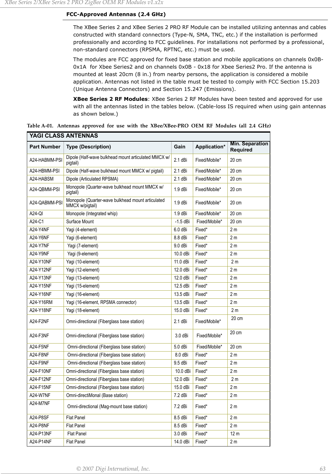
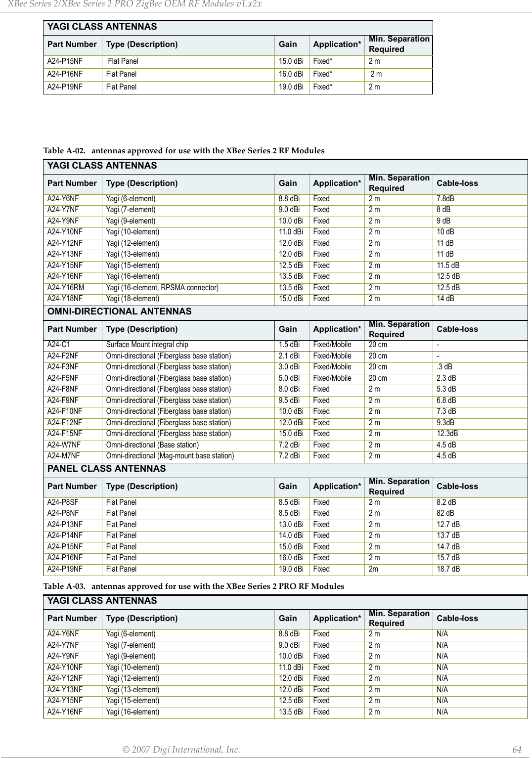
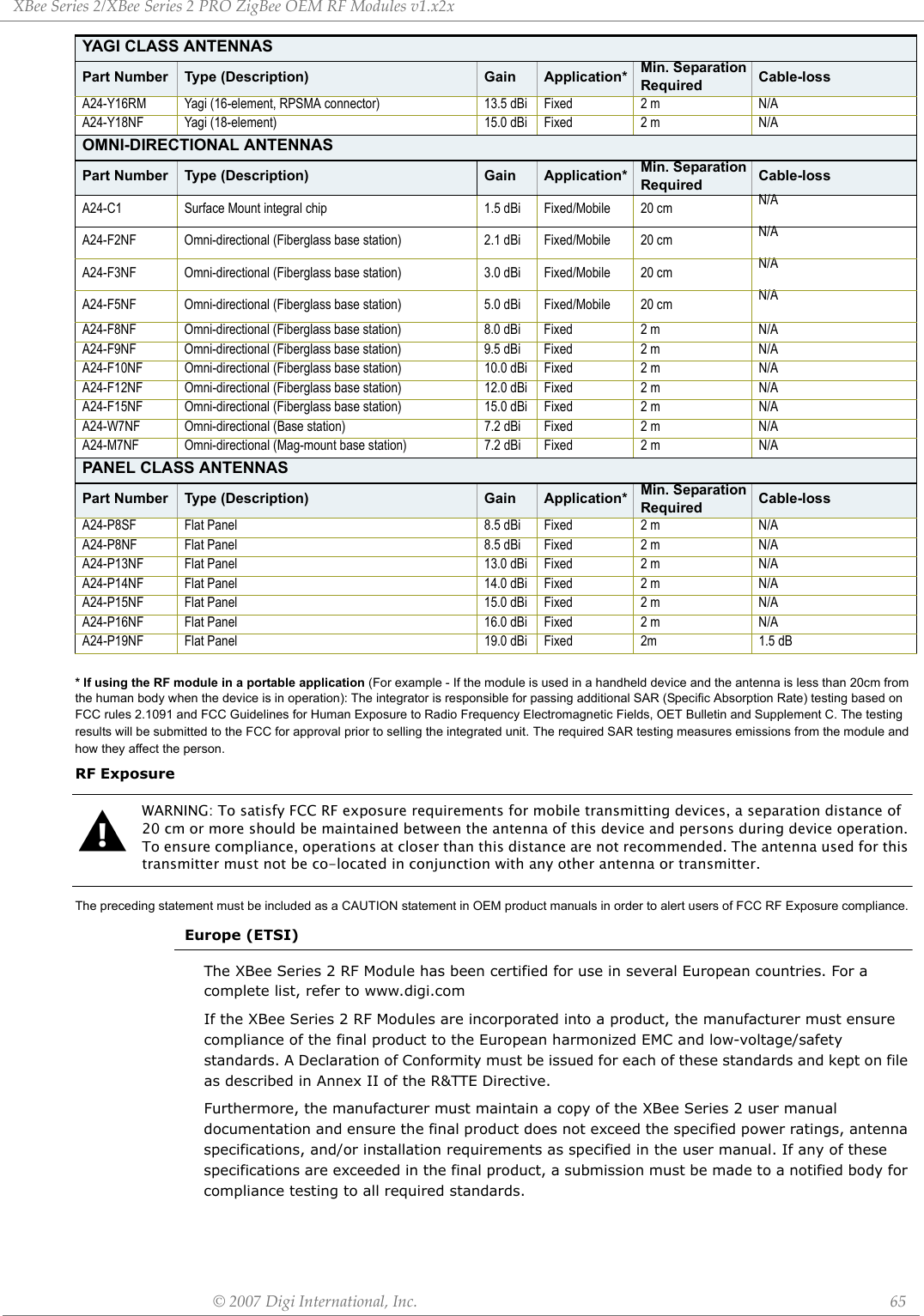
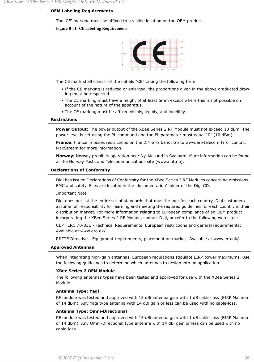
![©2007DigiInternational,Inc. 62AppendixB:AgencyCertificationsUnited States FCCThe XBee Series 2 RF Module complies with Part 15 of the FCC rules and regulations. Compliance with the labeling requirements, FCC notices and antenna usage guidelines is required.To fufill FCC Certification, the OEM must comply with the following regulations:OEM Labeling RequirementsWARNING: The Original Equipment Manufacturer (OEM) must ensure that FCC labeling requirements are met. This includes a clearly visible label on the outside of the final product enclosure that displays the contents shown in the figure below.Required FCC Label for OEM products containing the XBee Series 2 RF Module Required FCC Label for OEM products containing the XBee Series 2 PRO RF Module FCC NoticesIMPORTANT: The XBee Series 2 and XBEE Series 2 PRO RF Module have been certified by the FCC for use with other products without any further certification (as per FCC section 2.1091). Modifications not expressly approved by Digi could void the user's authority to operate the equipment.IMPORTANT: OEMs must test final product to comply with unintentional radiators (FCC section 15.107 & 15.109) before declaring compliance of their final product to Part 15 of the FCC Rules.IMPORTANT: The RF module has been certified for remote and base radio applications. If the module will be used for portable applications, the device must undergo SAR testing.This equipment has been tested and found to comply with the limits for a Class B digital device, pursuant to Part 15 of the FCC Rules. These limits are designed to provide reasonable protection against harmful interference in a residential installation. This equipment generates, uses and can radiate radio frequency energy and, if not installed and used in accordance with the instructions, may cause harmful interference to radio communications. However, there is no guarantee that interference will not occur in a particular installation. If this equipment does cause harmful interference to radio or television reception, which can be determined by turning the equipment off and on, the user is encouraged to try to correct the interference by one or more of the following measures: Re-orient or relocate the receiving antenna, Increase the separation between the equipment and receiver, Connect equipment and receiver to outlets on different circuits, or Consult the dealer or an experienced radio/TV technician for help.1. The system integrator must ensure that the text on the external label provided with this device is placed on the outside of the final product. [Figure A-01] 2. XBee Series 2 RF Module may only be used with antennas that have been tested and approved for use with this module [refer to the antenna tables in this section].Contains FCC ID: OUR-XBEE2*The enclosed device complies with Part 15 of the FCC Rules. Operation is subject to the following two conditions: (i.) this device may not cause harmful interference and (ii.) this device must accept any interference received, including interference that may cause undesired operation.Contains FCC ID:MCQ-XBEEPRO2*The enclosed device complies with Part 15 of the FCC Rules. Operation is subject to the following two conditions: (i.) this device may not cause harmful interference and (ii.) this device must accept any interference received, including interference that may cause undesired operation.](https://usermanual.wiki/Digi/XBEEPRO2.USERS-MANUAL/User-Guide-865868-Page-62.png)
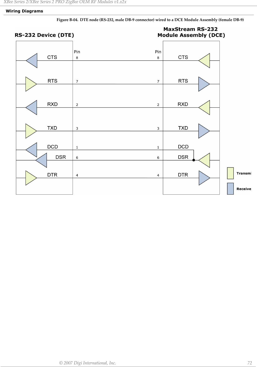
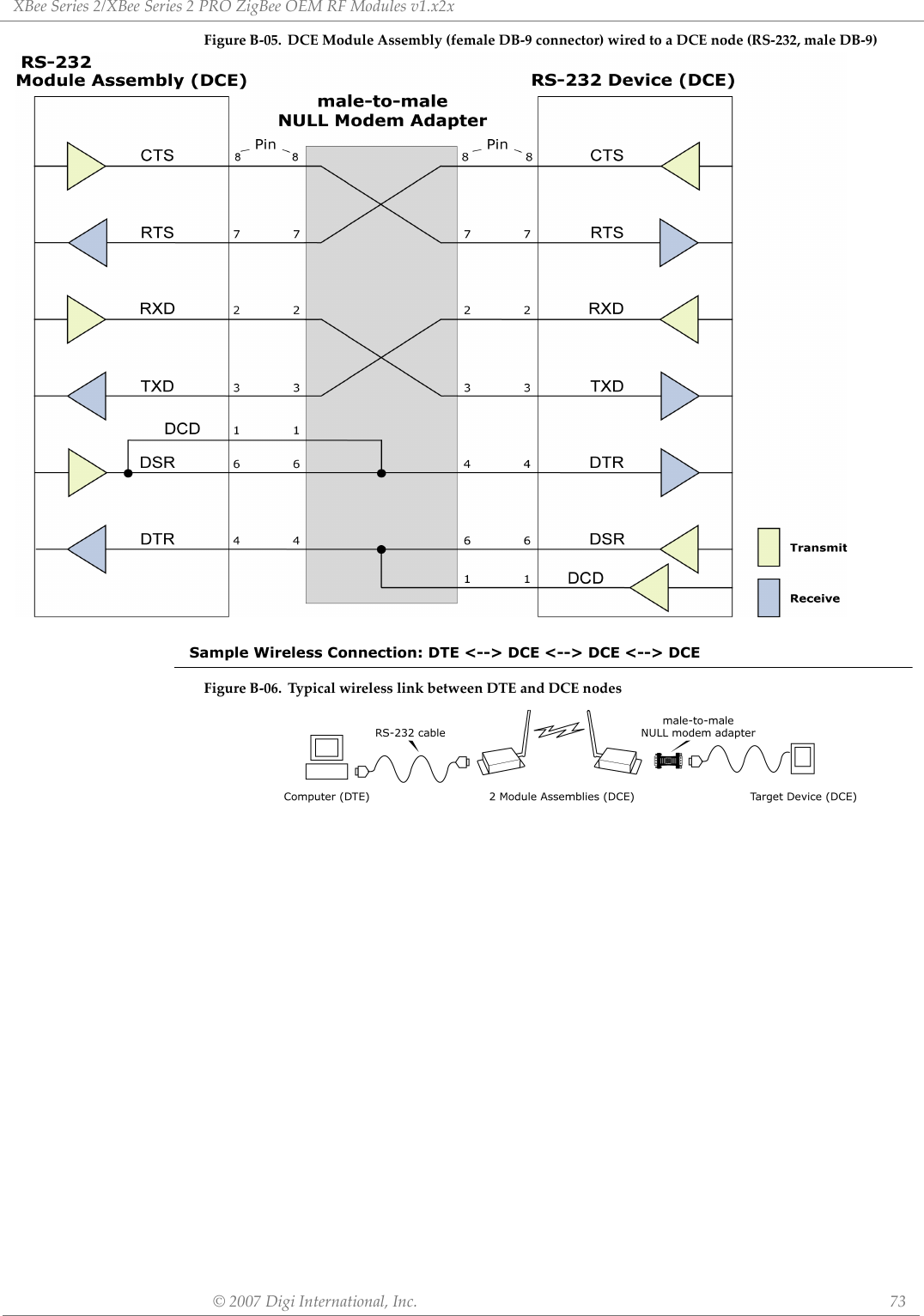
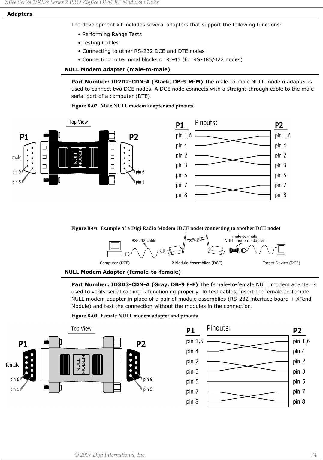
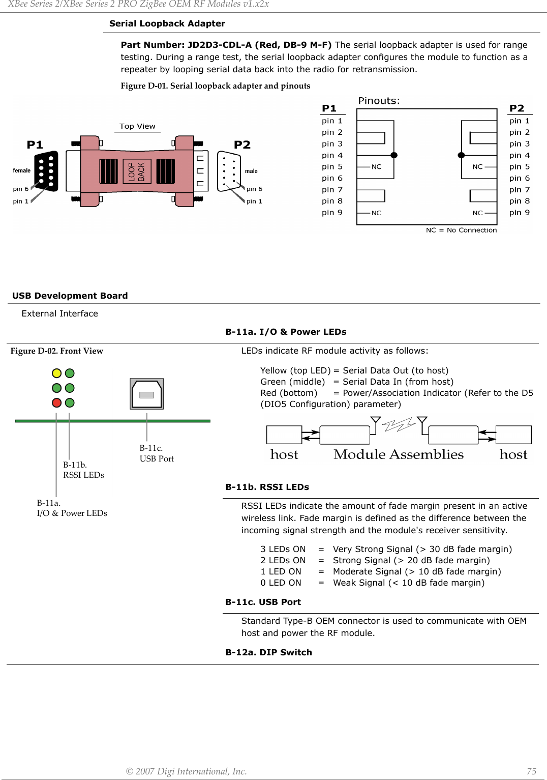
![©2007DigiInternational,Inc. 69AppendixD:DevelopmentGuideXBee Series 2 Development KitsThe XBee Series 2 Professional Development Kit includes the hardware and software needed to rapidly create long range wireless data links between nodes (XBee Series 2 Starter Kits that contain fewer modules and accessories are also available).Interfacing OptionsThe development kit includes RS-232 and USB interface boards. The boards provide a connection to PC ports and therefore give access to the RF module registries. Parameters stored in the registry allow OEMs and integrators to customize the modules to suite the needs of their data radio systems.The following sections illustrate how to use the interface boards for development purposes. The MaxStream Interface board provides means for connecting the module to any node that has an available RS-232 or USB connector. Since the module requires signals to enter at TTL voltages, one of the main functions of the interface board is to convert signals between TTL levels and RS-232 and USB levels.Tab leD‐01. ItemsIncludedintheDevelopmentKitItem Qty. Description Part #XBee Series 2 Module 5(1) OEM RF Module, AT Coordinator with wire antenna (1) OEM RF Module, AT Router/End Device with wire antenna(1) OEM RF Module, AT Router/End Device with U.FL antenna(1) OEM RF Module, AT Router/End Device with chip antenna(1) OEM RF Module, AT Router/End Device with SMA antennaXB24-BWIt-002XB24-BWIT-004XB24-BUIT-004XB24-BCIT-004XB24-BSIT-004RS-232 Development Board 4 Board for interfacing between modules and RS-232 nodes(Converts signal levels, displays diagnostic info, & more) XBIB-RUSB Development Board 1 Board for interfacing between modules & USB nodes(Converts signal levels, displays diagnostic info, & more) XBIB-URS-232 Cable (6’, straight-through) 1Cable for connecting RS-232 interface board with DTE nodes(nodes that have a male serial DB-9 port - such as most PCs) JD2D3-CDS-6FUSB Cable (6’) 1 Cable for connecting USB interface board to USB nodes JU1U2-CSB-6FSerial Loopback Adapter 1[Red] Adapter for configuring the module assembly (module + RS-232interface board) to function as a repeater for range testing JD2D3-CDL-ANULL Modem Adapter (male-to-male) 1[Black] Adapter for connecting the module assembly (module + RS-232interface board) to other DCE (female DB-9) nodes JD2D2-CDN-ANULL Modem Adapter (female-to-female) 1[Gray] Adapter for connecting serial nodes. It allows users to bypass the radios to verify serial cabling is functioning properly. JD3D3-CDN-APower Adapter (9VDC, 1 A) 1 Adapter for powering the RS-232 development board JP5P2-9V11-6FBattery Clip (9V) 1 Clip for remotely powering the RS-232 board w/ a 9V battery JP2P3-C2C-4IRPSMA Antenna 2 RPSMA half-wave dipole antenna (2.4 GHz, 2.1 dB) A24-HASM-450RF Cable Assembly 2 Adapter for connecting RPSMA antenna to U.FL connector JF1R6-CR3-4ICD 1 Documentation and Software MD0030Quick Start Guide 1 Step-by-step instruction on how to create wireless links & test range capabilities of the modules MD0026](https://usermanual.wiki/Digi/XBEEPRO2.USERS-MANUAL/User-Guide-865868-Page-69.png)

![©2007DigiInternational,Inc. 79AppendixE:AdditionalInformation1-Year WarrantyXBee Series 2 RF Modules from Digi, Inc. (the "Product") are warranted against defects in materi-als and workmanship under normal use, for a period of 1-year from the date of purchase. In the event of a product failure due to materials or workmanship, Digi will repair or replace the defective product. For warranty service, return the defective product to MaxStream, shipping prepaid, for prompt repair or replacement.The foregoing sets forth the full extent of MaxStream's warranties regarding the Product. Repair or replacement at MaxStream's option is the exclusive remedy. THIS WARRANTY IS GIVEN IN LIEU OF ALL OTHER WARRANTIES, EXPRESS OR IMPLIED, AND DIGI SPECIFICALLY DISCLAIMS ALL WARRANTIES OF MERCHANTABILITY OR FITNESS FOR A PARTICULAR PURPOSE. IN NO EVENT SHALL DIGI, ITS SUPPLIERS OR LICENSORS BE LIABLE FOR DAMAGES IN EXCESS OF THE PUR-CHASE PRICE OF THE PRODUCT, FOR ANY LOSS OF USE, LOSS OF TIME, INCONVENIENCE, COM-MERCIAL LOSS, LOST PROFITS OR SAVINGS, OR OTHER INCIDENTAL, SPECIAL OR CONSEQUENTIAL DAMAGES ARISING OUT OF THE USE OR INABILITY TO USE THE PRODUCT, TO THE FULL EXTENT SUCH MAY BE DISCLAIMED BY LAW. SOME STATES DO NOT ALLOW THE EXCLUSION OR LIMITATION OF INCIDENTAL OR CONSEQUENTIAL DAMAGES. THEREFORE, THE FOREGOING EXCLUSIONS MAY NOT APPLY IN ALL CASES. This warranty provides specific legal rights. Other rights which vary from state to state may also apply.Ordering InformationFigureE‐01.DivisionsoftheXBeeSeries2RFModulePartNumbersʺContact DigiFree and unlimited technical support is included with every Digi Radio Modem sold. For the best in wireless data solutions and support, please use the following resources:Digi’s office hours are 8:00 am - 5:00 pm [U.S. Central Standard Time]Technical Support: Phone. (866) 765-9885 toll-free U.S.A. & Canada (801) 765-9885 WorldwideLive Chat. www.digi.com E-Mail. support@digi.comX B 2 4 -B I T -0 0Antenna Types S = RPSMAW = Wire AntennaC = Chip AntennaU = U.FL ConnectorFirmware versions1 = Coordinator; API Operation2 = Coordinator; Transparent Operation3 = Router/End Device; API Operation4 = Router/End Device, Transparent Operation](https://usermanual.wiki/Digi/XBEEPRO2.USERS-MANUAL/User-Guide-865868-Page-79.png)