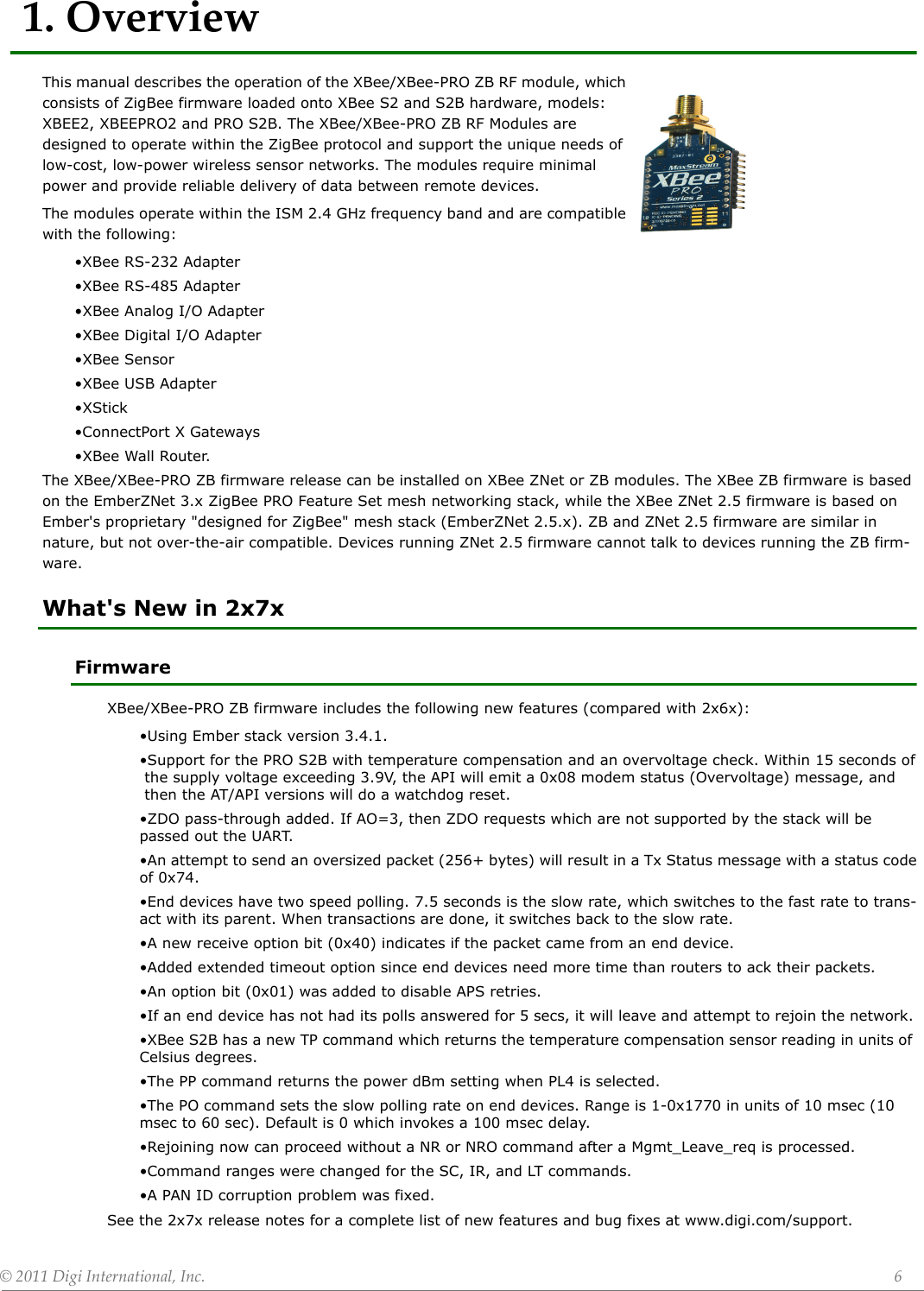
Digi XBEEPRO2 XBee PRO Series 2 OEM RF Module User Manual XBee XBee PRO ZB RF Modules
Digi International Inc XBee PRO Series 2 OEM RF Module XBee XBee PRO ZB RF Modules
Digi >
Contents
- 1. USERS MANUAL
- 2. Revised Used Manual
Revised Used Manual

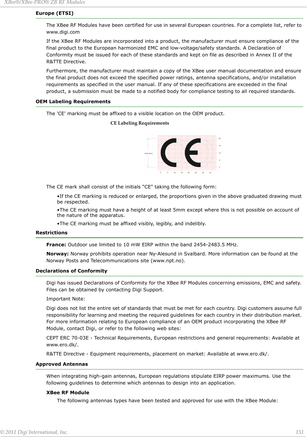
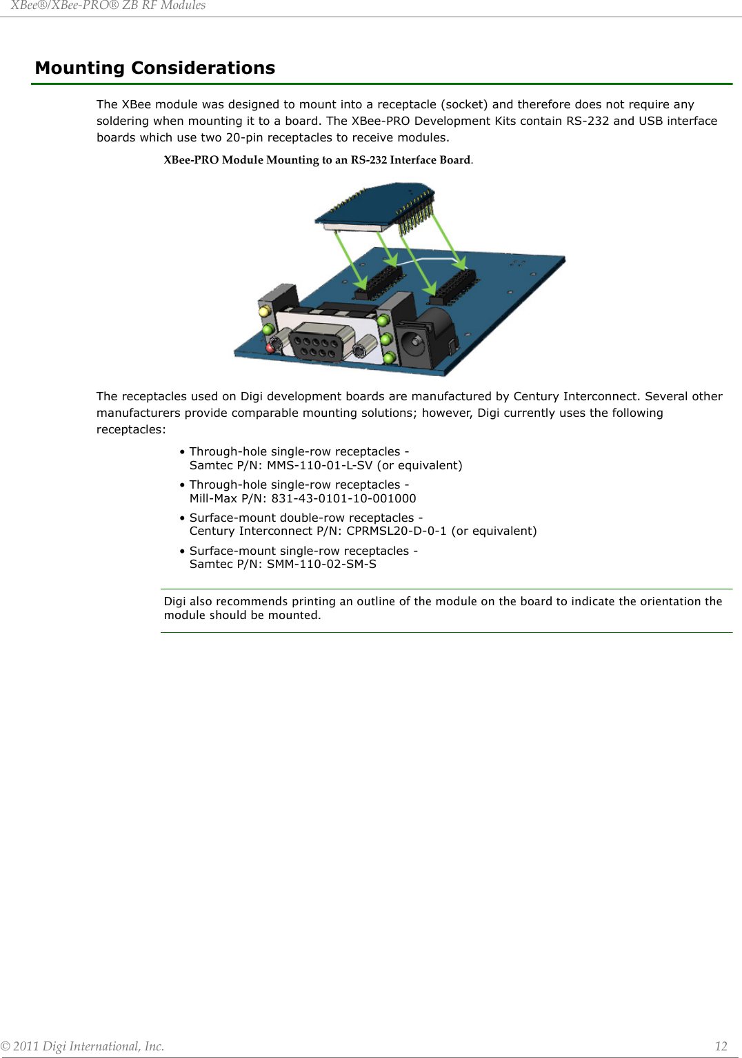
![XBee®/XBee‐PRO®ZBRFModules©2011DigiInternational,Inc. 2© 2011 Digi International, Inc. All rights reservedNopartofthecontentsofthismanualmaybetransmittedorreproducedinanyformorbyanymeanswithoutthewrittenpermissionofDigiInternational,Inc.ZigBee®isaregisteredtrademarkoftheZigBeeAlliance.XBee®andXBee‐PRO®areregisteredtrademarksofDigiInternational,Inc.Technical Support: Phone: (866) 765-9885 toll-free U.S.A. & Canada(801) 765-9885 Worldwide8:00 am - 5:00 pm [U.S. Mountain Time]Live Chat: www.digi.com Online Support: http://www.digi.com/support/eservice/login.jspEmail: rf-experts@digi.com](https://usermanual.wiki/Digi/XBEEPRO2.Revised-Used-Manual/User-Guide-1544897-Page-2.png)

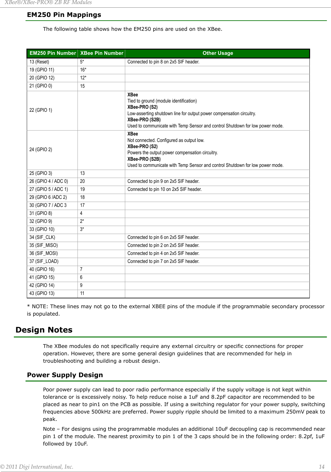
![XBee®/XBee‐PRO®ZBRFModules©2011DigiInternational,Inc. 13Pin Signals• Signal Direction is specified with respect to the module• See Design Notes section below for details on pin connections.PinAssignmentsfortheXBee/XBee‐PROModules(Low‐assertedsignalsaredistinguishedwithahorizontallineabovesignalname.)Pin # Name Direction Default State Description1 VCC - - Power supply2 DOUT Output Output UART Data Out3 DIN / CONFIG Input Input UART Data In4 DIO12 Both Disabled Digital I/O 125RESET Both Open-Collector with pull-upModule Reset (reset pulse must be at least 200 ns)6 RSSI PWM / DIO10 Both Output RX Signal Strength Indicator / Digital IO7 DIO11 Both Input Digital I/O 118 [reserved] - Disabled Do not connect9DTR / SLEEP_RQ/ DIO8 Both Input Pin Sleep Control Line or Digital IO 810 GND - - Ground11 DIO4 Both Disabled Digital I/O 412 CTS / DIO7 Both Output Clear-to-Send Flow Control or Digital I/O 7. CTS, if enabled, is an output.13 ON / SLEEP Output Output Module Status Indicator or Digital I/O 914 VREF Input -Not used for EM250. Used for programmable secondary processor.For compatibility with other XBEE modules, we recommend connecting this pin voltage reference if Analog sampling is desired. Otherwise, connect to GND.15 Associate / DIO5 Both Output Associated Indicator, Digital I/O 516 RTS / DIO6 Both Input Request-to-Send Flow Control, Digital I/O 6. RTS, if enabled, is an input.17 AD3 / DIO3 Both Disabled Analog Input 3 or Digital I/O 318 AD2 / DIO2 Both Disabled Analog Input 2 or Digital I/O 219 AD1 / DIO1 Both Disabled Analog Input 1 or Digital I/O 120 AD0 / DIO0 / Commissioning Button Both Disabled Analog Input 0, Digital IO 0, or Commissioning Button](https://usermanual.wiki/Digi/XBEEPRO2.Revised-Used-Manual/User-Guide-1544897-Page-13.png)

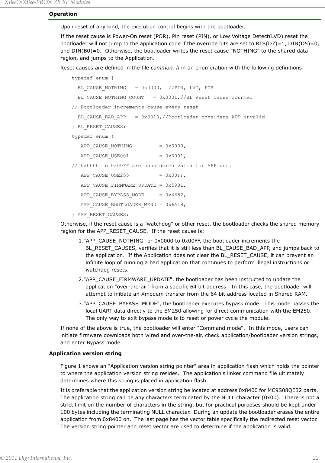
![XBee®/XBee‐PRO®ZBRFModules©2011DigiInternational,Inc. 23Application Interrupt Vector table and Linker Command FileSince the bootloader flash region is read-only, the interrupt vector table is redirected to the region 0xF1C0 to 0xF1FD so that application developers can use hardware interrupts. Note that in order for Application interrupts to function properly, the Application's linker command file (*.prm extension) must be modified appropriately to allow the linker to place the developers code in the correct place in memory. For example, the developer desires to use the serial communications port SCI1 receive interrupt. The developer would add the following line to the Codewarrior linker command file for the project…VECTOR ADDRESS 0x0000F1E0 vSci1RxThis will inform the linker that the interrupt function "vSci1Rx()" should be placed at address 0x0000F1E0. Next, the developer should add a file to their project "vector_table.c" that creates an array of function pointers to the ISR routines used by the application…Eg.extern void _Startup(void);/* _Startup located in Start08.c */extern void vSci1Rx(void);/* sci1 rx isr */ extern short iWriteToSci1(unsigned char *);void vDummyIsr(void);#pragma CONST_SEG VECTORSvoid (* const vector_table[])(void) = /* Relocated Interrupt vector table */{vDummyIsr,/* Int.no. 0 Vtpm3ovf (at F1C0)Unassigned */vDummyIsr, /* Int.no. 1 Vtpm3ch5 (at F1C2) Unassigned */vDummyIsr, /* Int.no. 2 Vtpm3ch4 (at F1C4) Unassigned */vDummyIsr, /* Int.no. 3 Vtpm3ch3 (at F1C6) Unassigned */vDummyIsr, /* Int.no. 4 Vtpm3ch2 (at F1C8) Unassigned */vDummyIsr, /* Int.no. 5 Vtpm3ch1 (at F1CA) Unassigned */vDummyIsr, /* Int.no. 6 Vtpm3ch0 (at F1CC) Unassigned */vDummyIsr, /* Int.no. 7 Vrtc (at F1CE) Unassigned */vDummyIsr, /* Int.no. 8 Vsci2tx (at F1D0) Unassigned */vDummyIsr, /* Int.no. 9 Vsci2rx (at F1D2) Unassigned */vDummyIsr, /* Int.no. 10 Vsci2err (at F1D4) Unassigned */vDummyIsr, /* Int.no. 11 Vacmpx (at F1D6) Unassigned */vDummyIsr, /* Int.no. 12 Vadc (at F1D8) Unassigned */vDummyIsr, /* Int.no. 13 Vkeyboard (at F1DA) Unassigned */vDummyIsr, /* Int.no. 14 Viic (at F1DC) Unassigned */vDummyIsr, /* Int.no. 15 Vsci1tx (at F1DE) Unassigned */vSci1Rx, /* Int.no. 16 Vsci1rx (at F1E0) SCI1RX */vDummyIsr, /* Int.no. 17 Vsci1err (at F1E2) Unassigned */vDummyIsr, /* Int.no. 18 Vspi (at F1E4) Unassigned */vDummyIsr, /* Int.no. 19 VReserved12 (at F1E6) Unassigned */vDummyIsr, /* Int.no. 20 Vtpm2ovf (at F1E8) Unassigned */vDummyIsr, /* Int.no. 21 Vtpm2ch2 (at F1EA) Unassigned */vDummyIsr, /* Int.no. 22 Vtpm2ch1 (at F1EC) Unassigned */vDummyIsr, /* Int.no. 23 Vtpm2ch0 (at F1EE) Unassigned */vDummyIsr, /* Int.no. 24 Vtpm1ovf (at F1F0) Unassigned */vDummyIsr, /* Int.no. 25 Vtpm1ch2 (at F1F2) Unassigned */vDummyIsr, /* Int.no. 26 Vtpm1ch1 (at F1F4) Unassigned */vDummyIsr, /* Int.no. 27 Vtpm1ch0 (at F1F6) Unassigned */](https://usermanual.wiki/Digi/XBEEPRO2.Revised-Used-Manual/User-Guide-1544897-Page-23.png)
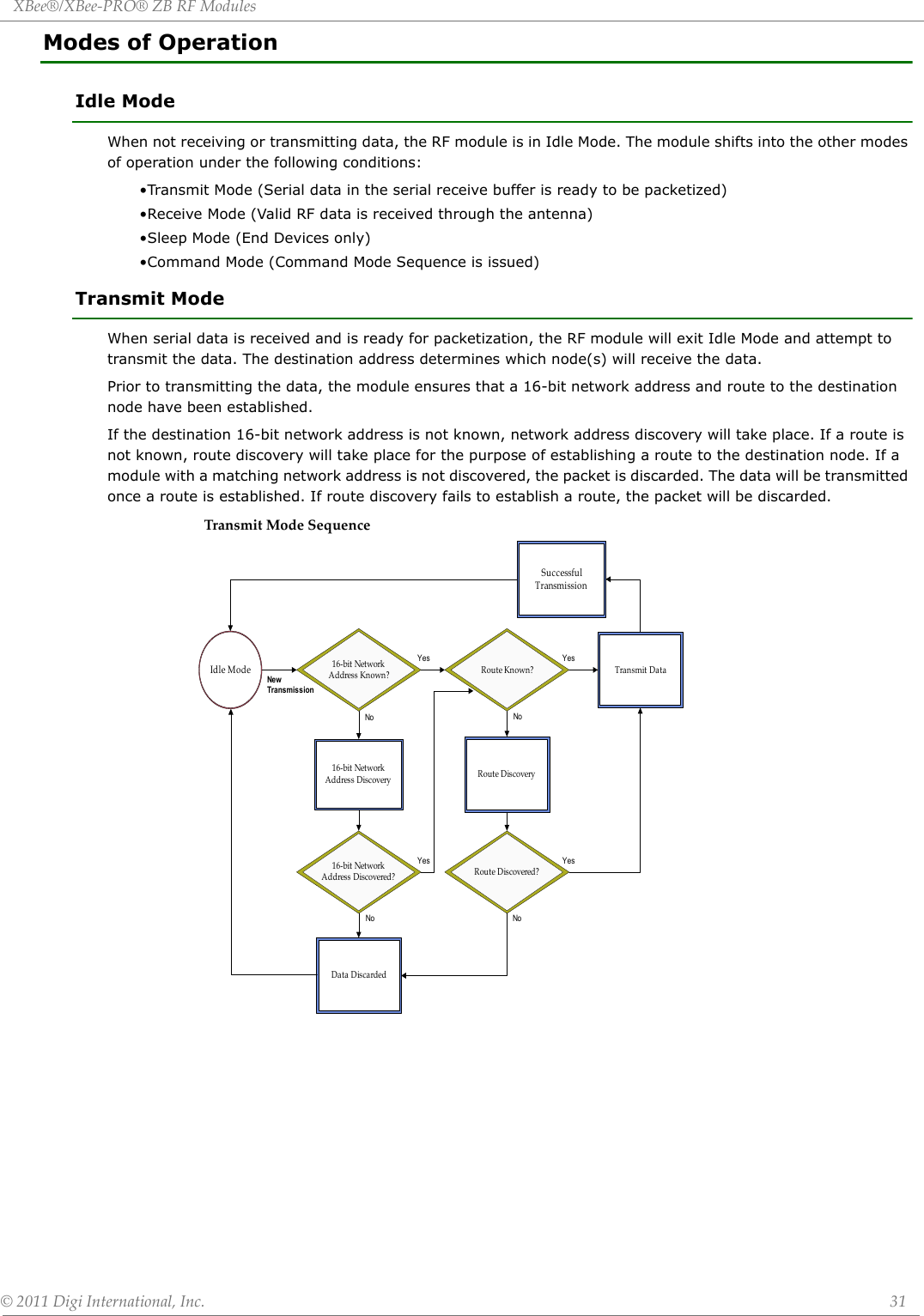
![XBee®/XBee‐PRO®ZBRFModules©2011DigiInternational,Inc. 32When data is transmitted from one node to another, a network-level acknowledgement is transmitted back across the established route to the source node. This acknowledgement packet indicates to the source node that the data packet was received by the destination node. If a network acknowledgement is not received, the source node will re-transmit the data. It is possible in rare circumstances for the destination to receive a data packet, but for the source to not receive the network acknowledgment. In this case, the source will retransmit the data, which could cause the destination to receive the same data packet multiple times. The XBee modules do not filter out duplicate packets. The application should include provisions to address this potential issueSee Data Transmission and Routing in chapter 4 for more information. Receive ModeIf a valid RF packet is received, the data is transferred to the serial transmit buffer.Command ModeTo modify or read RF Module parameters, the module must first enter into Command Mode - a state in which incoming serial characters are interpreted as commands. Refer to the API Mode section in chapter 9 for an alternate means of configuring modules.AT Command ModeTo Enter AT Command Mode:Send the 3-character command sequence “+++” and observe guard times before and after the com-mand characters. [Refer to the “Default AT Command Mode Sequence” below.]Default AT Command Mode Sequence (for transition to Command Mode):•No characters sent for one second [GT (Guard Times) parameter = 0x3E8]•Input three plus characters (“+++”) within one second [CC (Command Sequence Character) parame-ter = 0x2B.]•No characters sent for one second [GT (Guard Times) parameter = 0x3E8]Once the AT command mode sequence has been issued, the module sends an "OK\r" out the DOUT pin. The "OK\r" characters can be delayed if the module has not finished transmitting received serial data.When command mode has been entered, the command mode timer is started (CT command), and the module is able to receive AT commands on the DIN pin. All of the parameter values in the sequence can be modified to reflect user preferences.NOTE: Failure to enter AT Command Mode is most commonly due to baud rate mismatch. By default, the BD (Baud Rate) parameter = 3 (9600 bps).To Send AT Commands:Send AT commands and parameters using the syntax shown below.Figure2‐01.SyntaxforsendingATCommandsTo read a parameter value stored in the RF module’s register, omit the parameter field.The preceding example would change the RF module Destination Address (Low) to “0x1F”. To store the new value to non-volatile (long term) memory, subsequently send the WR (Write) command.For modified parameter values to persist in the module’s registry after a reset, changes must be saved to non-volatile memory using the WR (Write) Command. Otherwise, parameters are restored to previously saved values after the module is reset.Command Response](https://usermanual.wiki/Digi/XBEEPRO2.Revised-Used-Manual/User-Guide-1544897-Page-32.png)
![XBee®/XBee‐PRO®ZBRFModules©2011DigiInternational,Inc. 33When a command is sent to the module, the module will parse and execute the command. Upon successful execution of a command, the module returns an “OK” message. If execution of a command results in an error, the module returns an “ERROR” message.Applying Command Changes Any changes made to the configuration command registers through AT commands will not take effect until the changes are applied. For example, sending the BD command to change the baud rate will not change the actual baud rate until changes are applied. Changes can be applied in one of the following ways:•The AC (Apply Changes) command is issued.•AT command mode is exited.To Exit AT Command Mode:1. Send the ATCN (Exit Command Mode) command (followed by a carriage return). [OR]2. If no valid AT Commands are received within the time specified by CT (Command Mode Timeout) Command, the RF module automatically returns to Idle Mode. For an example of programming the RF module using AT Commands and descriptions of each config-urable parameter, please see the Command Reference Table chapter. Sleep ModeSleep modes allow the RF module to enter states of low power consumption when not in use. The XBee RF modules support both pin sleep (sleep mode entered on pin transition) and cyclic sleep (module sleeps for a fixed time). XBee sleep modes are discussed in detail in chapter 6.](https://usermanual.wiki/Digi/XBEEPRO2.Revised-Used-Manual/User-Guide-1544897-Page-33.png)
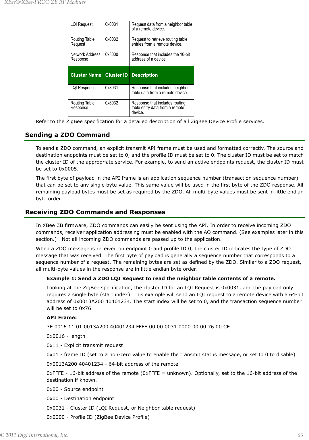
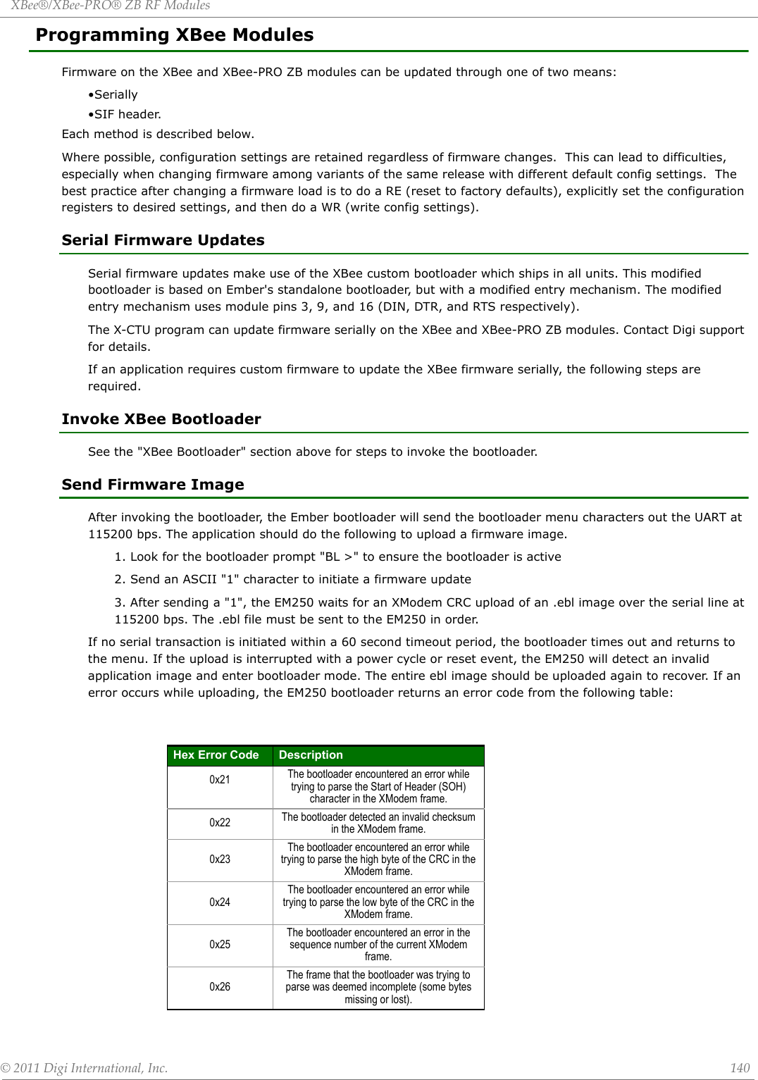
![XBee®/XBee‐PRO®ZBRFModules©2011DigiInternational,Inc. 670x00 - Broadcast radius0x00 - Tx Options0x76 - Transaction sequence number0x00 - Required payload for LQI request command0xCE - Checksum (0xFF - SUM (all bytes after length))Description:This API frame sends a ZDO LQI request (neighbor table request) to a remote device to obtain data from its neighbor table. Recall that the AO command must be set correctly on an API device to enable the explicit API receive frames in order to receive the ZDO response.Example 2: Send a ZDO Network Address Request to discover the 16-bit address of a remote.Looking at the ZigBee specification, the cluster ID for a network Address Request is 0x0000, and the payload only requires the following:[64-bit address] + [Request Type] + [Start Index]This example will send a Network Address Request as a broadcast transmission to discover the 16-bit address of the device with a 64-bit address of 0x0013A200 40401234. The request type and start index will be set to 0, and the transaction sequence number will be set to 0x44API Frame:7E 001F 11 01 00000000 0000FFFF FFFE 00 00 0000 0000 00 00 44 34124040 00A21300 00 00 330x001F - length0x11 - Explicit transmit request0x01 - frame ID (set to a non-zero value to enable the transmit status message, or set to 0 to disable)0x00000000 0000FFFF - 64-bit address for a broadcast transmission0xFFFE - Set to this value for a broadcast transmission.0x00 - Source endpoint0x00 - Destination endpoint0x0000 - Cluster ID (Network Address Request)0x0000 - Profile ID (ZigBee Device Profile)0x00 - Broadcast radius0x00 - Tx Options0x44 - Transaction sequence number0x34124040 00A21300 00 00 - Required payload for Network Address Request command0x33 - Checksum (0xFF - SUM (all bytes after length))Description:This API frame sends a broadcast ZDO Network Address Request to obtain the 16-bit address of a device with a 64-bit address of 0x0013A200 40401234. Note the bytes for the 64-bit address were inserted in little endian byte order. All multi-byte fields in the API payload of a ZDO command must have their data inserted in little endian byte order. Also recall that the AO command must be set correctly on an API device to enable the explicit API receive frames in order to receive the ZDO response.Transmission TimeoutsThe ZigBee stack includes two kinds of transmission timeouts, depending on the nature of the destination device. For destination devices such as routers whose receiver is always on, a unicast timeout is used. The unicast timeout estimates a timeout based on the number of unicast hops the packet should traverse to get data to the destination device. For transmissions destined for end devices, the ZigBee stack uses an extended timeout that includes the unicast timeout (to route data to the end device's parent), and it includes a timeout for the end device to finish sleeping, wake, and poll the parent for data.The ZigBee stack includes some provisions for a device to detect if the destination is an end device or not. The ZigBee stack uses the unicast timeout unless it knows the destination is an end device.](https://usermanual.wiki/Digi/XBEEPRO2.Revised-Used-Manual/User-Guide-1544897-Page-67.png)

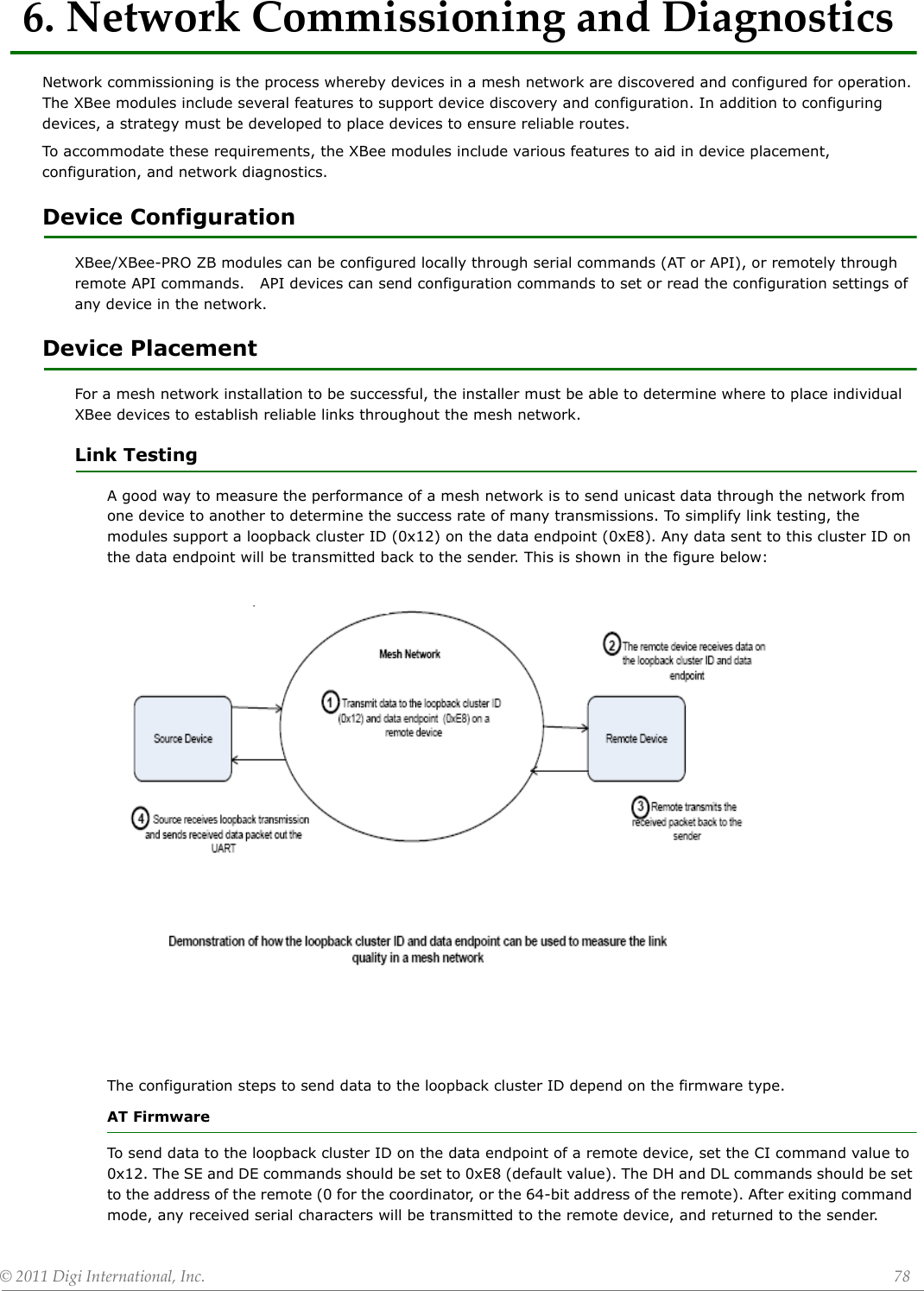
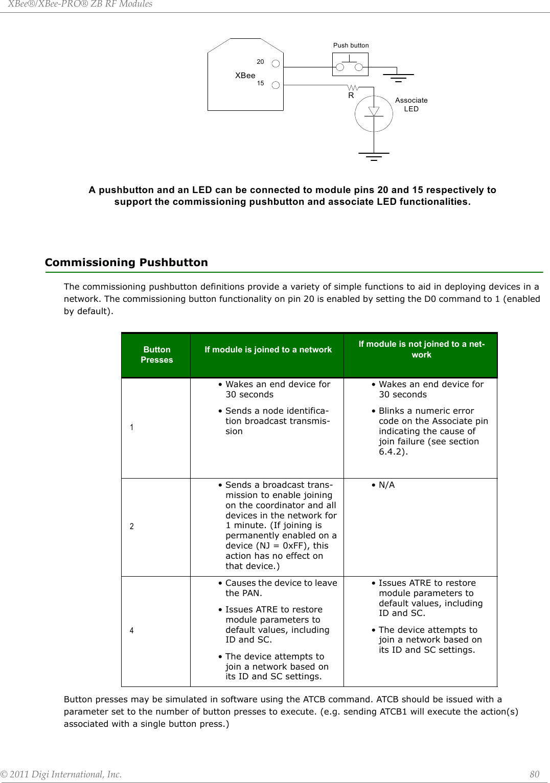
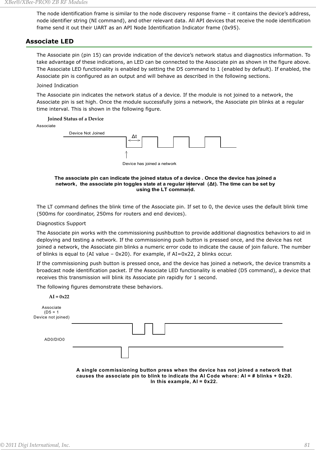
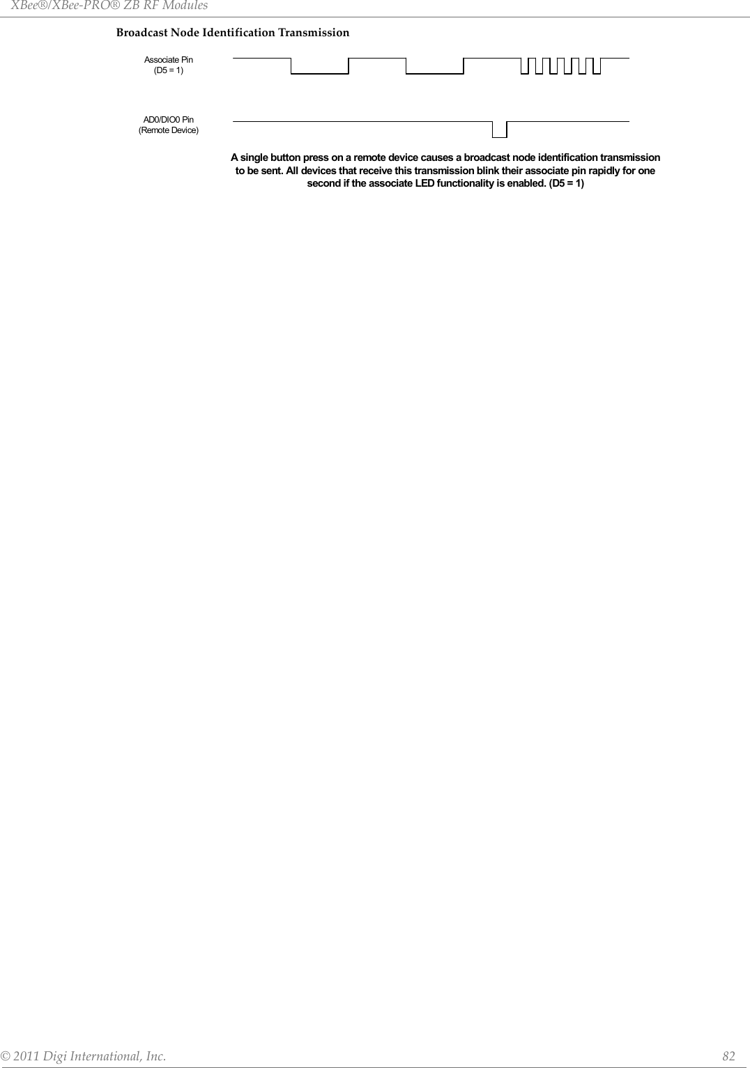
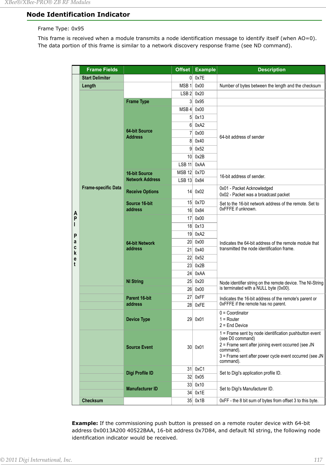
![XBee®/XBee‐PRO®ZBRFModules©2011DigiInternational,Inc. 79API FirmwareSend an Explicit Addressing ZigBee Command API frame (0x11) using 0x12 as the cluster ID and 0xE8 as the source and destination endpoint. Data packets received by the remote will be echoed back to the sender.RSSI IndicatorsIt is possible to measure the received signal strength on a device using the DB command. DB returns the RSSI value (measured in –dBm) of the last received packet. However, this number can be misleading. The DB value only indicates the received signal strength of the last hop. If a transmission spans multiple hops, the DB value provides no indication of the overall transmission path, or the quality of the worst link – it only indicates the quality of the last link and should be used sparingly.The DB value can be determined in hardware using the RSSI/PWM module pin (pin 6). If the RSSI PWM functionality is enabled (P0 command), when the module receives data, the RSSI PWM is set to a value based on the RSSI of the received packet. (Again, this value only indicates the quality of the last hop.) This pin could potentially be connected to an LED to indicate if the link is stable or not.Device DiscoveryNetwork DiscoveryThe network discovery command can be used to discover all Digi modules that have joined a network. Issuing the ND command sends a broadcast node discovery command throughout the network. All devices that receive the command will send a response that includes the device’s addressing information, node identifier string (see NI command), and other relevant information. This command is useful for generating a list of all module addresses in a network.When a device receives the node discovery command, it waits a random time before sending its own response. The maximum time delay is set on the ND sender with the NT command. The ND originator includes its NT setting in the transmission to provide a delay window for all devices in the network. Large networks may need to increase NT to improve network discovery reliability. The default NT value is 0x3C (6 seconds). ZDO DiscoveryThe ZigBee Device Profile includes provisions to discover devices in a network that are supported on all ZigBee devices (including non-Digi products). These include the LQI Request (cluster ID 0x0031) and the Network Update Request (cluster ID 0x0038). The LQI Request can be used to read the devices in the neighbor table of a remote device, and the Network Update Request can be used to have a remote device do an active scan to discover all nearby ZigBee devices. Both of these ZDO commands can be sent using the XBee Explicit API transmit frame (0x11). See the API chapter for details. Refer to the ZigBee specification for formatting details of these two ZDO frames.Joining AnnounceAll ZigBee devices send a ZDO Device Announce broadcast transmission when they join a ZigBee network (ZDO cluster ID 0x0013). These frames will be sent out the XBee's UART as an Explicit Rx Indicator API frame (0x91) if AO is set to 1. The device announce payload includes the following information:[ Sequence Number] + [16-bit address] + [64-bit address] + [Capability]The 16-bit and 64-bit addresses are received in little-endian byte order (LSB first). See the ZigBee specification for details.Commissioning Pushbutton and Associate LEDThe XBee modules support a set of commissioning and LED behaviors to aid in device deployment and commissioning. These include the commissioning pushbutton definitions and associate LED behaviors. These features can be supported in hardware as shown below.CommissioningPushbuttonandAssociateLEDFunctionalities](https://usermanual.wiki/Digi/XBEEPRO2.Revised-Used-Manual/User-Guide-1544897-Page-79.png)
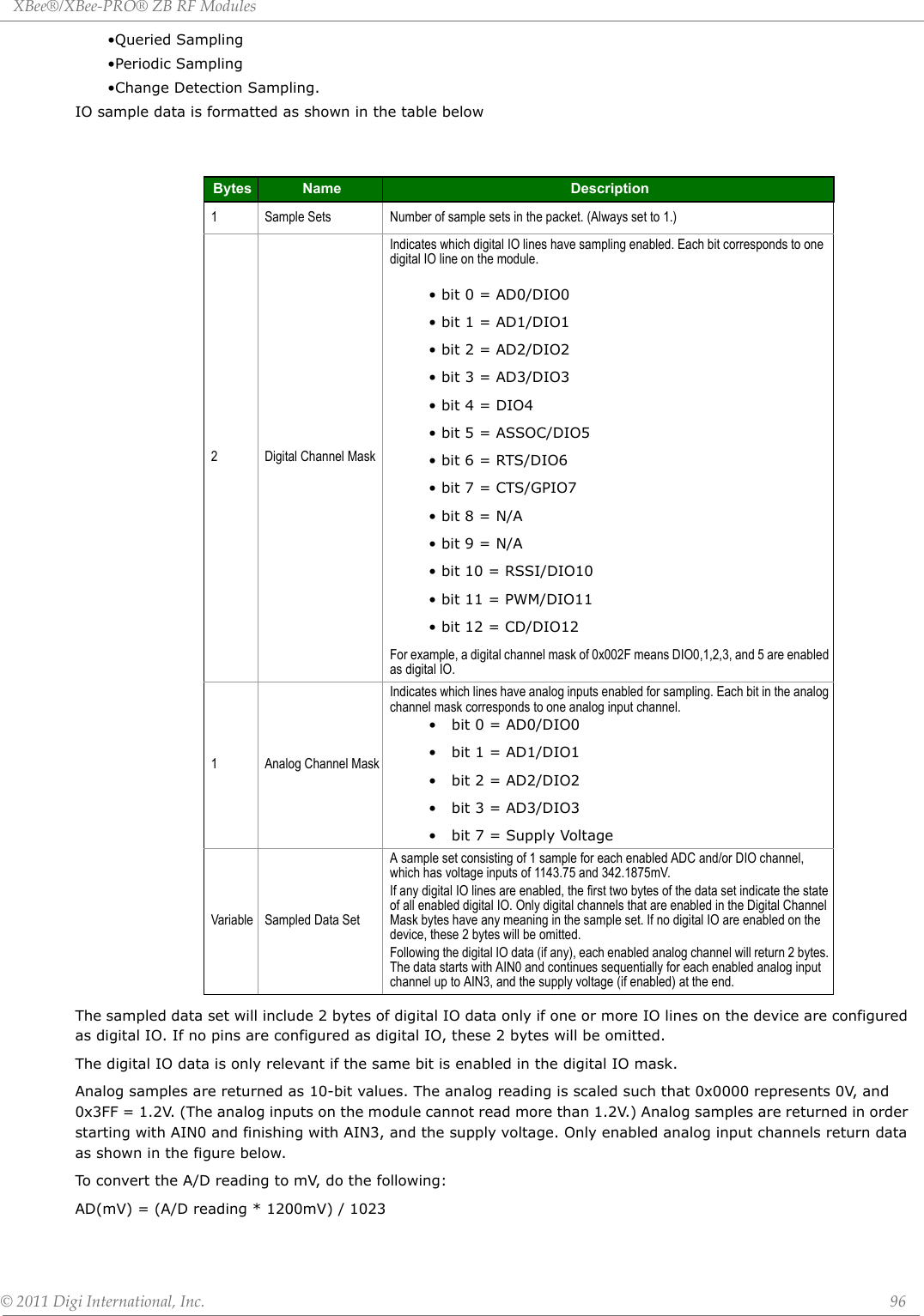
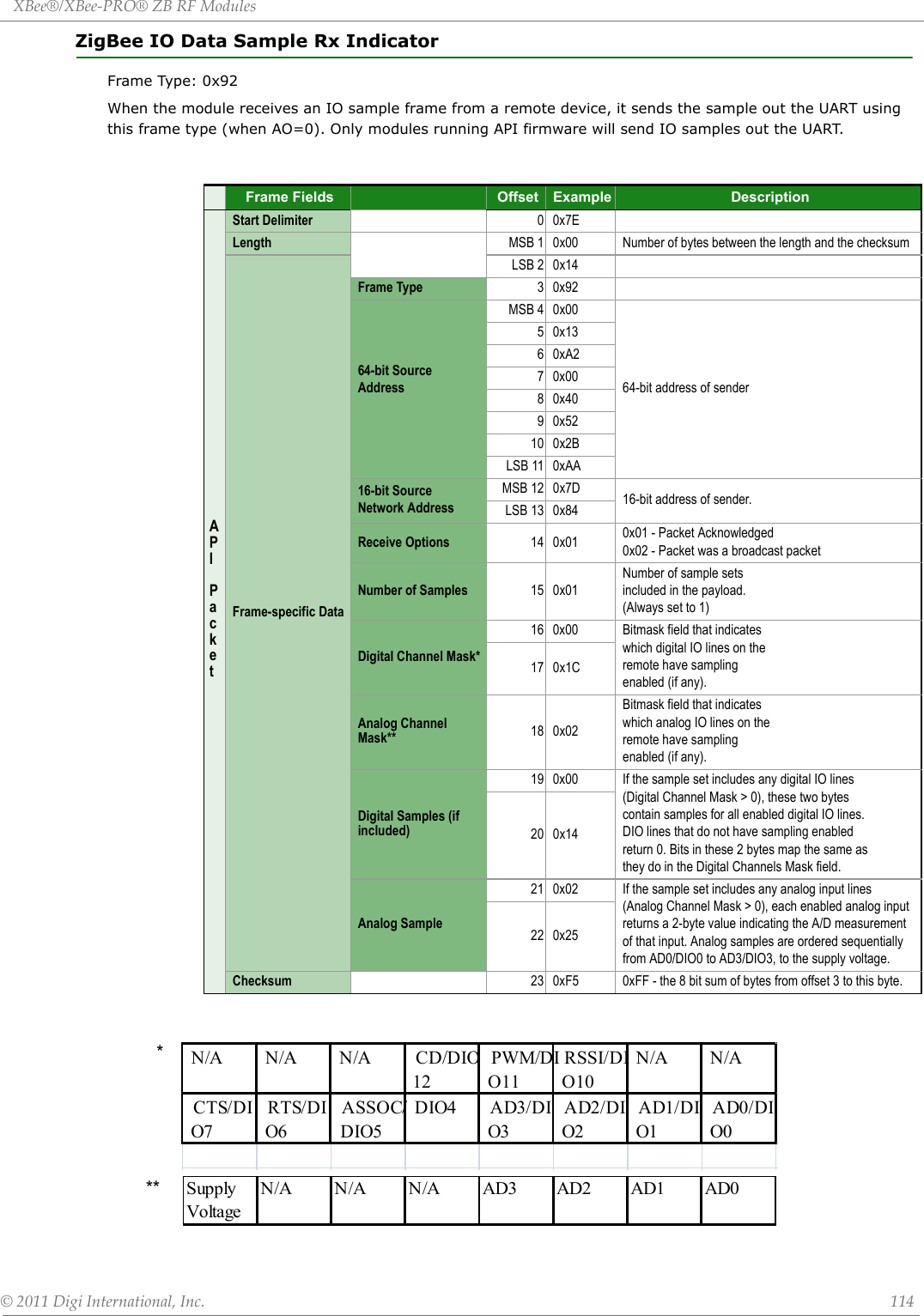
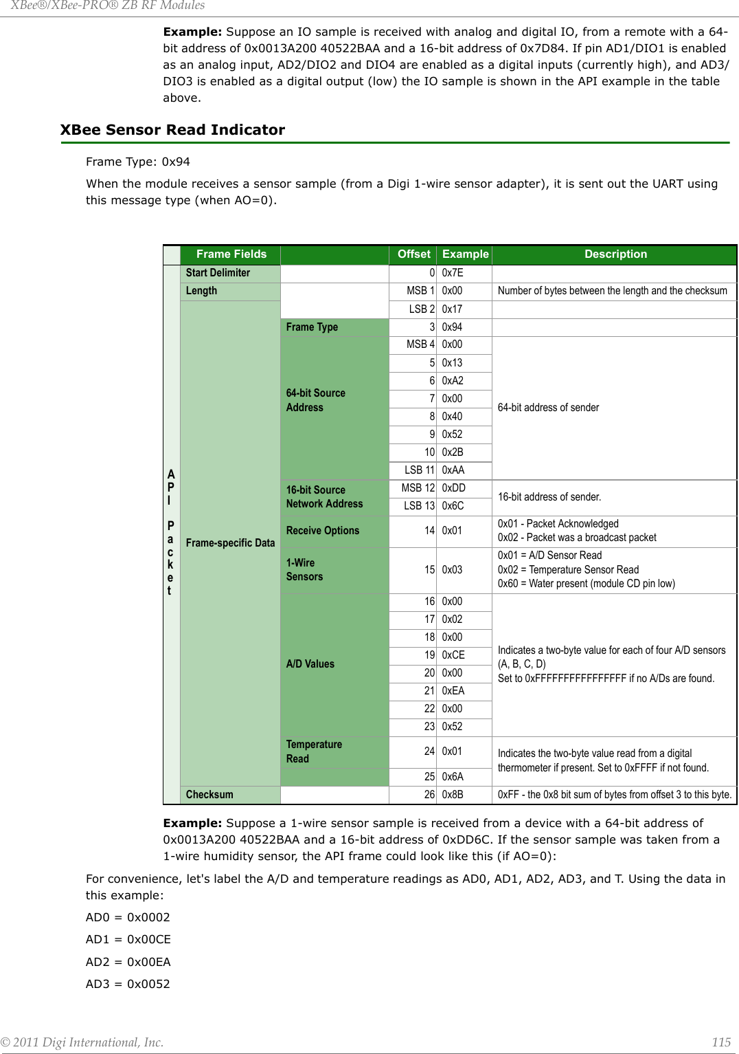
![XBee®/XBee‐PRO®ZBRFModules©2011DigiInternational,Inc. 97The reading in the sample frame represents voltage inputs of 1143.75 and 342.1875mV for AD0 and AD1 respectively.Queried SamplingThe IS command can be sent to a device locally, or to a remote device using the API remote command frame (see chapter 8 for details). When the IS command is sent, the receiving device samples all enabled digital IO and analog input channels and returns an IO sample. If IS is sent locally, the IO sample is sent out the UART. If the IS command was received as a remote command, the IO sample is sent over-the-air to the device that sent the IS command.If the IS command is issued in AT firmware, the module returns a carriage return-delimited list containing the above-listed fields. The API firmware returns an AT command response packet with the IO data included in the command data portion of the response frame.The following table shows an example of the fields in an IS response.Periodic IO SamplingPeriodic sampling allows an XBee/XBee-PRO module to take an IO sample and transmit it to a remote device at a periodic rate. The periodic sample rate is set by the IR command. If IR is set to 0, periodic sampling is disabled. For all other values of IR, data will be sampled after IR milliseconds have elapsed and transmitted to a remote device. The DH and DL commands determine the destination address of the IO samples. DH and DL can be set to 0 to transmit to the coordinator, or to the 64-bit address of the remote device (SH and SL). Only devices running API firmware can send IO data samples out their UART. Devices running AT firmware will discard received IO data samples.A sleeping end device will transmit periodic IO samples at the IR rate until the ST timer expires and the device can resume sleeping.Change Detection SamplingModules can be configured to transmit a data sample immediately whenever a monitored digital IO pin changes state. The IC command is a bitmask that can be used to set which digital IO lines should be monitored for a state change. If one or more bits in IC is set, an IO sample will be transmitted as soon as a state change is observed in one of the monitored digital IO lines. Change detection samples are transmitted to the 64-bit address specified by DH and DL. RSSI PWMThe XBee module features an RSSI/PWM pin (pin 6) that, if enabled, will adjust the PWM output to indicate the signal strength of the last received packet. The P0 (P-zero) command is used to enable the RSSI pulse width modulation (PWM) output on the pin. If P0 is set to 1, the RSSI/PWM pin will output a pulse width modulated signal where the frequency is adjusted based on the received signal strength of the last packet. Otherwise, for all other P0 settings, the pin can be used for general purpose IO.When a data packet is received, if P0 is set to enable the RSSI/PWM feature, the RSSI PWM output is adjusted based on the RSSI of the last packet. The RSSI/PWM output will be enabled for a time based on the RP command. Each time an RF packet is received, the RSSI/PWM output is adjusted based on the RSSI of the new packet, and the RSSI timer is reset. If the RSSI timer expires, the RSSI/PWM pin is driven low. RP is measured in 100ms units and defaults to a value of 40 (4 seconds).The RSSI PWM runs at 12MHz and has 2400 total counts (200us period).Example Sample AT Response0x01 [1 sample set]0x0C0C [Digital Inputs: DIO 2, 3, 10, 11 low]0x03 [Analog Inputs: A/D 0, 1]0x0408 [Digital input states: DIO 3, 10 high, DIO 2, 11 low]0x03D0 [Analog input ADIO 0= 0x3D0]0x0124 [Analog input ADIO 1=0x120]](https://usermanual.wiki/Digi/XBEEPRO2.Revised-Used-Manual/User-Guide-1544897-Page-97.png)
![XBee®/XBee‐PRO®ZBRFModules©2011DigiInternational,Inc. 101ChecksumTo test data integrity, a checksum is calculated and verified on non-escaped data.To calculate: Not including frame delimiters and length, add all bytes keeping only the lowest 8 bits of the result and subtract the result from 0xFF.To verify: Add all bytes (include checksum, but not the delimiter and length). If the checksum is correct, the sum will equal 0xFF.API ExamplesExample: Create an API AT command frame to configure an XBee to allow joining (set NJ to 0xFF). The frame should look like: 0x7E 0x00 0x05 0x08 0x01 0x4E 0x4A 0xFF 5FWhere 0x0005 = length 0x08 = AT Command API frame type 0x01 = Frame ID (set to non-zero value) 0x4E4A = AT Command ('NJ') 0xFF = value to set command to 0x5F = ChecksumThe checksum is calculated as [0xFF - (0x08 + 0x01 + 0x4E + 0x4A + 0xFF)]Example: Send an ND command to discover the devices in the PAN. The frame should look like:0x7E 0x00 0x04 0x08 0x01 0x4E 0x44 0x64Where 0x0004 = length 0x08 = AT Command API frame type 0x01 = Frame ID (set to non-zero value) 0x4E44 = AT command ('ND') 0x64 = ChecksumThe checksum is calculated as [0xFF - (0x08 + 0x01 + 0x4E + 0x44)]Example: Send a remote command to the coordinator to set AD1/DIO1 as a digital input (D1=3) and apply changes to force the IO update. The API remote command frame should look like:0x7E 0x00 0x10 0x17 0x01 0x00 0x00 0x00 0x00 0x00 0x00 0x00 0x00 0xFF 0xFE 0x02 0x44 0x31 0x03 0x70Where 0x10 = length (16 bytes excluding checksum)0x17 = Remote Command API frame type0x01 = Frame ID0x0000000000000000 = Coordinator's address (can be replaced with coordinator's actual 64-bit address if known)0xFFFE = 16- bit Destination Address0x02 = Apply Changes (Remote Command Options)0x4431 = AT command ('D1')0x03 = Command Parameter (the parameter could also be sent as 0x0003 or 0x00000003)0x70 = Checksum](https://usermanual.wiki/Digi/XBEEPRO2.Revised-Used-Manual/User-Guide-1544897-Page-101.png)
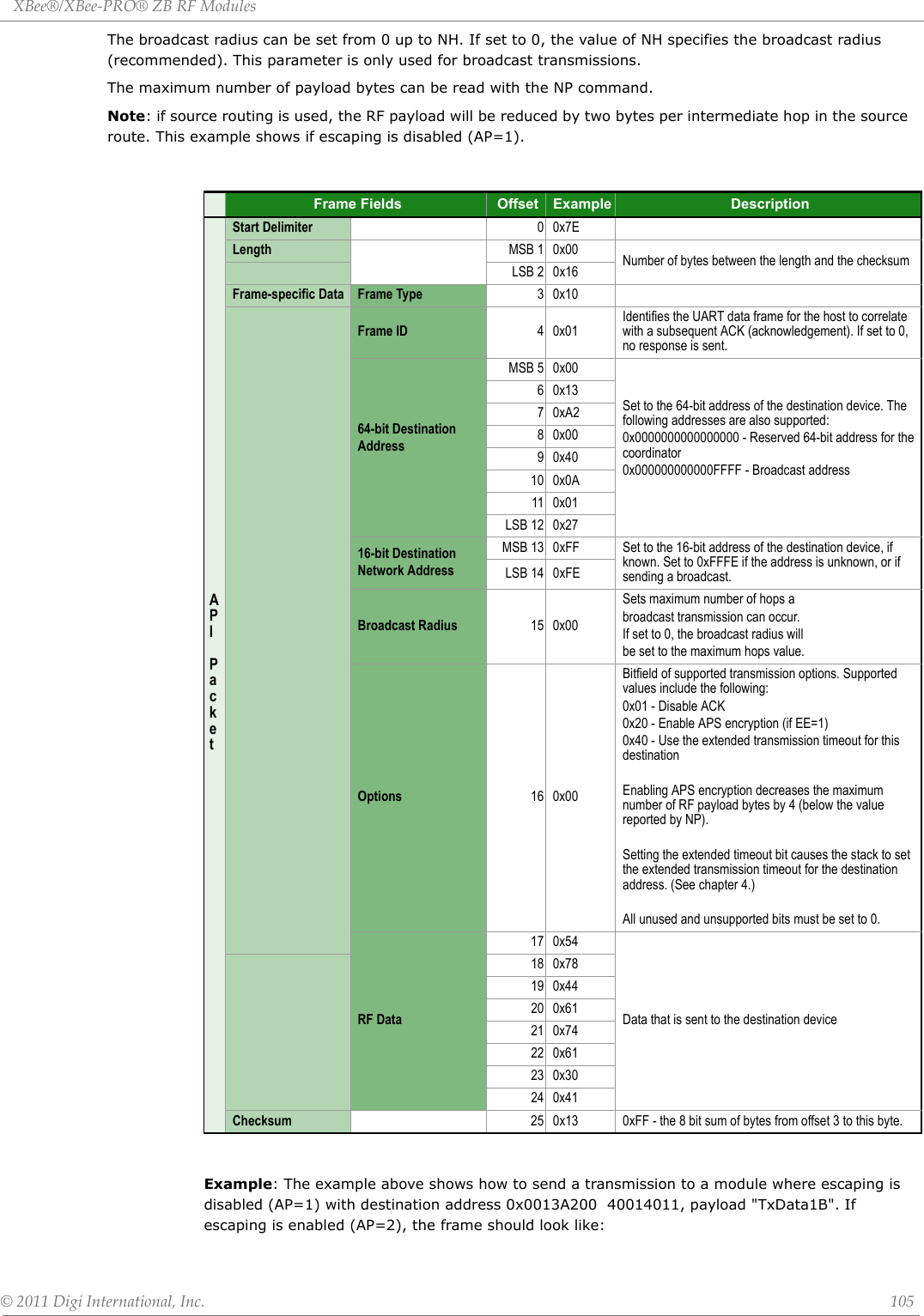
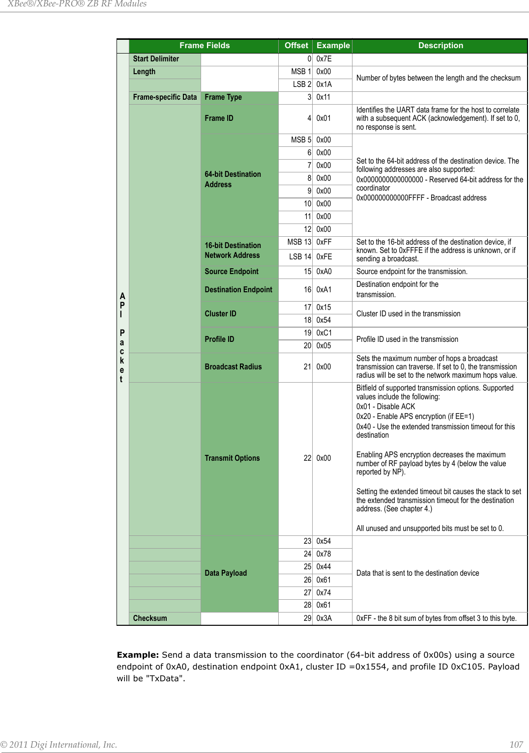
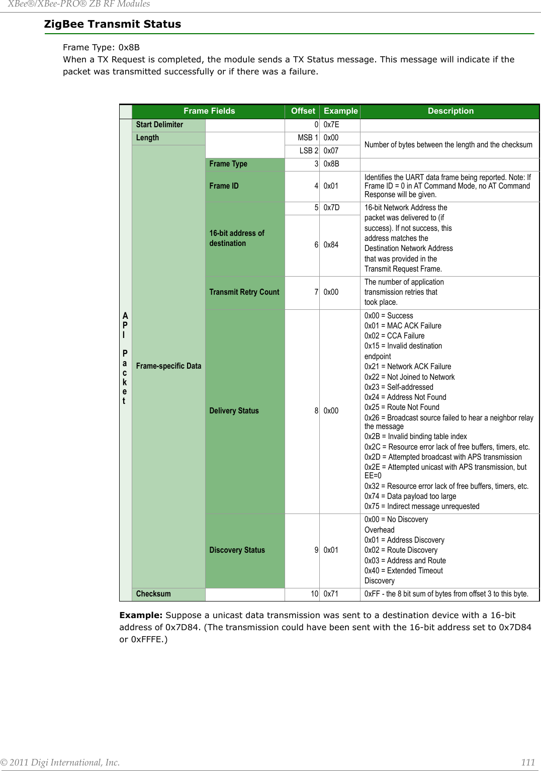
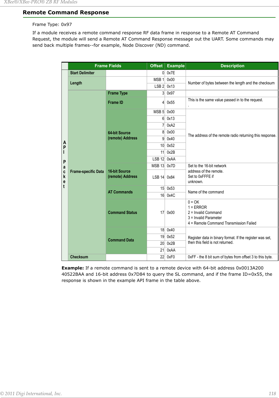
![XBee®/XBee‐PRO®ZBRFModules©2011DigiInternational,Inc. 106 0x7E 0x00 0x16 0x10 0x01 0x00 0x7D 0x33 0xA2 0x00 0x40 0x0A 0x01 0x27 0xFF 0xFE 0x00 0x00 0x54 0x78 0x44 0x61 0x74 0x61 0x30 0x41 0x7D 0x33The checksum is calculated (on all non-escaped bytes) as [0xFF - (sum of all bytes from API frame type through data payload)]. Example: Send a transmission to the coordinator without specifying the coordinator's 64-bit address. The API transmit request frame should look like:0x7E 0x00 0x16 0x10 0x01 0x00 0x00 0x00 0x00 0x00 0x00 0x00 0x00 0xFF 0xFE 0x00 0x00 0x54 0x78 032 0x43 0x6F 0x6F 0x72 0x64 0xFCWhere 0x16 = length (22 bytes excluding checksum) 0x10 = ZigBee Transmit Request API frame type 0x01 = Frame ID (set to non-zero value) 0x0000000000000000 = Coordinator's address (can be replaced with coordinator's actual 64-bit address if known 0xFFFE = 16-bit Destination Address 0x00 = Broadcast radius 0x00 = Options 0x547832436F6F7264 = Data payload ("Tx2Coord") 0xFC = ChecksumExplicit Addressing ZigBee Command Frame Frame Type: 0x11Allows ZigBee application layer fields (endpoint and cluster ID) to be specified for a data transmission.Similar to the ZigBee Transmit Request, but also requires ZigBee application layer addressing fields to be specified (endpoints, cluster ID, profile ID). An Explicit Addressing Request API frame causes the module to send data as an RF packet to the specified destination, using the specified source and destination endpoints, cluster ID, and profile ID.The 64-bit destination address should be set to 0x000000000000FFFF for a broadcast transmission (to all devices). The coordinator can be addressed by either setting the 64-bit address to all 0x00s and the 16-bit address to 0xFFFE, OR by setting the 64-bit address to the coordinator's 64-bit address and the 16-bit address to 0x0000. For all other transmissions, setting the 16-bit address to the correct 16-bit address can help improve performance when transmitting to multiple destinations. If a 16-bit address is not known, this field should be set to 0xFFFE (unknown). The Transmit Status frame (0x8B) will indicate the discovered 16-bit address, if successful.The broadcast radius can be set from 0 up to NH. If set to 0, the value of NH specifies the broadcast radius (recommended). This parameter is only used for broadcast transmissions.The maximum number of payload bytes can be read with the NP command. Note: if source routing is used, the RF payload will be reduced by two bytes per intermediate hop in the source route.](https://usermanual.wiki/Digi/XBEEPRO2.Revised-Used-Manual/User-Guide-1544897-Page-106.png)
![XBee®/XBee‐PRO®ZBRFModules©2011DigiInternational,Inc. 123Frame Fields Offset Example DescriptionAPI PacketStart Delimiter 00x7ELength MSB 1 0x00 Number of bytes between the length and the checksumFrame-specific Data LSB 2 0x17Frame Type 30x11Frame ID 40x01Identifies the UART data frame for the host to correlate with a subsequent transmit status. If set to 0, no transmit status frame will be sent out the UART.64-bit DestinationAddressMSB 5 0x0064-bit address of the destination device (big endian byte order). For unicast transmissions, set to the 64-bit address of the destination device, or to 0x0000000000000000 to send a unicast to the coordinator. Set to 0x000000000000FFFF for broadcast.60x0070x0080x0090x0010 0x0011 0xFF12 0xFF16-bit DestinationNetwork AddressMSB 13 0xFF 16-bit address of the destination device (big endian byte order). Set to 0xFFFE for broadcast, or if the 16-bit address is unknown. LSB 14 0xFESource Endpoint 15 0x00 Set to 0x00 for ZDO transmissions (endpoint 0 is the ZDO endpoint).Destination Endpoint 16 0x00 Set to 0x00 for ZDO transmissions (endpoint 0 is the ZDO endpoint).Cluster IDMSB 17 0x00 Set to the cluster ID that corresponds to the ZDO command being sent.0x0005 = Active Endpoints RequestLSB 18 0x05Profile ID MSB 19 0x00 Set to 0x0000 for ZDO transmissions (Profile ID 0x0000 is the ZigBee Device Profile that supports ZDOs).LSB 20 0x00Broadcast Radius 21 0x00Sets the maximum number of hops a broadcast transmission can traverse. If set to 0, the transmission radius will be set to the network maximum hops value.Transmit Options 22 0x00 All bits must be set to 0.Data PayloadTransaction Sequence Number 23 0x01 The required payload for a ZDO command. All multi-byte ZDO parameter values (u16, u32, 64-bit address) must be sent in little endian byte order.The Active Endpoints Request includes the following payload:[16-bit NwkAddrOfInterest]Note the 16-bit address in the API example (0x1234) is sent in little endian byte order (0x3412).ZDO Payload 24 0x3425 0x12Checksum 26 0xA6 0xFF minus the 8 bit sum of bytes from offset 3 to this byte.](https://usermanual.wiki/Digi/XBEEPRO2.Revised-Used-Manual/User-Guide-1544897-Page-123.png)
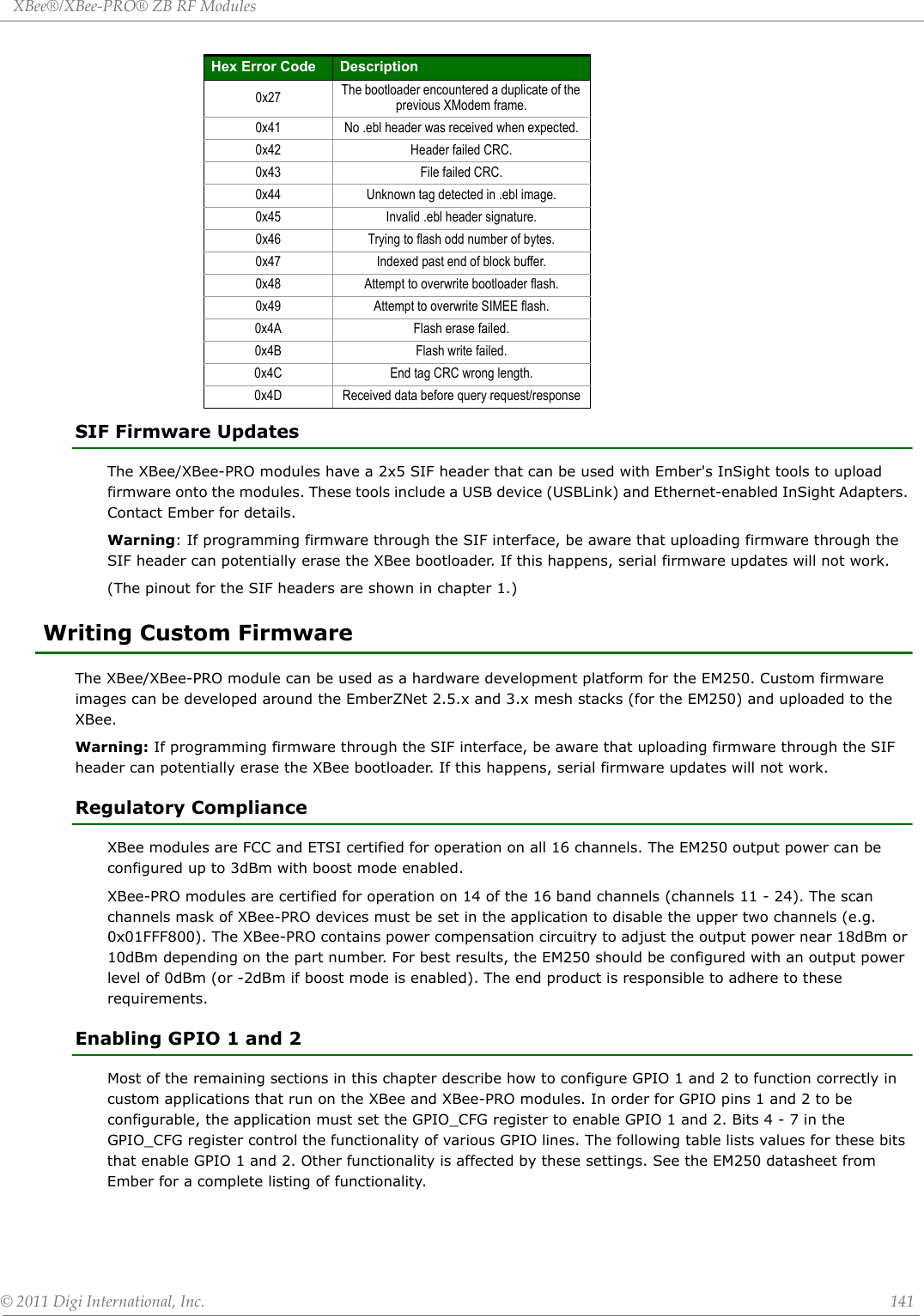
![©2011DigiInternational,Inc. 12910.XBeeCommandReferenceTablesAddressingNodetypesthatsupportthecommand:C=Coordinator,R=Router,E=EndDeviceAddressingCommandsATCommand Name and Description Node Type1Parameter Range DefaultDHDestination Address High.Set/Get the upper 32 bits of the 64-bit destination address. When combined with DL, it defines the 64-bit destination address for data transmission. Special definitions for DH and DL include 0x000000000000FFFF (broadcast) and 0x0000000000000000 (coordinator).CRE 0 - 0xFFFFFFFF 0DLDestination Address Low. Set/Get the lower 32 bits of the 64-bit destination address. When combined with DH, it defines the 64-bit destination address for data transmissions. Special definitions for DH and DL include 0x000000000000FFFF (broadcast) and 0x0000000000000000 (coordinator).CRE 0 - 0xFFFFFFFF 0xFFFF(Coordinator)0 (Router/End Device)MY 16-bit Network Address. Read the 16-bit network address of the module. A value of 0xFFFE means the module has not joined a ZigBee network CRE 0 - 0xFFFE[read-only] 0xFFFEMP 16-bit Parent Network Address. Read the 16-bit network address of the module's parent. A value of 0xFFFE means the module does not have a parent. E0 - 0xFFFE[read-only] 0xFFFENC Number of Remaining Children. Read the number of end device children that can join the device. If NC returns 0, then the device cannot allow any more end device children to join. CR 0 - MAX_CHILDREN(maximum varies) read-only SH Serial Number High. Read the high 32 bits of the module's unique 64-bit address. CRE 0 - 0xFFFFFFFF [read-only] factory-setSL Serial Number Low. Read the low 32 bits of the module's unique 64-bit address. CRE 0 - 0xFFFFFFFF[read-only] factory-setNINode Identifier. Stores a string identifier. The register only accepts printable ASCII data. In AT Command Mode, a string can not start with a space. A carriage return ends the command. Command will automatically end when maximum bytes for the string have been entered. This string is returned as part of the ND (Node Discover) command. This identifier is also used with the DN (Destination Node) command. In AT command mode, an ASCII comma (0x2C) cannot be used in the NI stringCRE 20-Byte printable ASCII stringASCII space character (0x20)SESource Endpoint. Set/read the ZigBee application layer source endpoint value. This value will be used as the source endpoint for all data transmissions. SE is only supported in AT firmware.The default value 0xE8 (Data endpoint) is the Digi data endpoint CRE 0 - 0xFF 0xE8DEDestination Endpoint. Set/read Zigbee application layer destination ID value. This value will be used as the destination endpoint all data transmissions. DE is only supported in AT firmware.The default value (0xE8) is the Digi data endpoint. CRE 0 - 0xFF 0xE8CICluster Identifier. Set/read Zigbee application layer cluster ID value. This value will be used as the cluster ID for all data transmissions. CI is only supported in AT firmware.The default value0x11 (Transparent data cluster ID).CRE 0 - 0xFFFF 0x11NPMaximum RF Payload Bytes. This value returns the maximum number of RF payload bytes that can be sent in a unicast transmission. If APS encryption is used (API transmit option bit enabled), the maximum payload size is reduced by 9 bytes. If source routing is used (AR < 0xFF), the maximum payload size is reduced further.Note: NP returns a hexadecimal value. (e.g. if NP returns 0x54, this is equivalent to 84 bytes)CRE 0 - 0xFFFF [read-only]DDDevice Type Identifier. Stores a device type value. This value can be used to differentiate different XBee-based devices. Digi reserves the range 0 - 0xFFFFFF.For example, Digi currently uses the following DD values to identify various ZigBee products:0x30001 - ConnectPort X8 Gateway0x30002 - ConnectPort X4 Gateway0x30003 - ConnectPort X2 Gateway0x30005 - RS-232 Adapter0x30006 - RS-485 Adapter0x30007 - XBee Sensor Adapter0x30008 - Wall Router0x3000A - Digital I/O Adapter0x3000B - Analog I/O Adapter0x3000C - XStick0x3000F - Smart Plug0x30011 - XBee Large Display0x30012 - XBee Small DisplayCRE 0 - 0xFFFFFFFF 0x30000](https://usermanual.wiki/Digi/XBEEPRO2.Revised-Used-Manual/User-Guide-1544897-Page-129.png)
![XBee®/XBee‐PRO®ZBRFModules©2011DigiInternational,Inc. 130NetworkingNetworkingCommandsATCommand Name and Description Node Type1Parameter Range DefaultCHOperating Channel. Read the channel number used for transmitting and receiving between RF modules. Uses 802.15.4 channel numbers. A value of 0 means the device has not joined a PAN and is not operating on any channel.CREXBee0, 0x0B - 0x1A (Channels 11-26)XBee-PRO (S2)0, 0x0B - 0x18 (Channels 11-24)XBee-PRO (S2B)0, 0x0B - 0x19(Channels 11-25)[read-only]DA Force Disassociation. End device will immediately disassociate from a Coordinator (if associated) and reattempt to associate. CRE - -IDExtended PAN ID. Set/read the 64-bit extended PAN ID. If set to 0, the coordinator will select a random extended PAN ID, and the router / end device will join any extended PAN ID. Changes to ID should be written to non-volatile memory using the WR command to preserve the ID setting if a power cycle occurs.CRE 0 - 0xFFFFFFFFFFFFFFFF 0OP Operating Extended PAN ID. Read the 64-bit extended PAN ID. The OP value reflects the operating extended PAN ID that the module is running on. If ID > 0, OP will equal ID. CRE 0x01 - 0xFFFFFFFFFFFFFFFF [read-only]NHMaximum Unicast Hops. Set / read the maximum hops limit. This limit sets the maximum broadcast hops value (BH) and determines the unicast timeout. The timeout is computed as (50 * NH) + 100 ms. The default unicast timeout of 1.6 seconds (NH=0x1E) is enough time for data and the acknowledgment to traverse about 8 hops.CRE 0 - 0xFF 0x1EBH Broadcast Hops. Set/Read the maximum number of hops for each broadcast data transmission. Setting this to 0 will use the maximum number of hops. CRE 0 - 0x1E 0OI Operating 16-bit PAN ID. Read the 16-bit PAN ID. The OI value reflects the actual 16-bit PAN ID the module is running on. CRE 0 - 0xFFFF [read-only]NTNode Discovery Timeout. Set/Read the node discovery timeout. When the network discovery (ND) command is issued, the NT value is included in the transmission to provide all remote devices with a response timeout. Remote devices wait a random time, less than NT, before sending their response.CRE 0x20 - 0xFF [x 100 msec] 0x3C (60d)NONetwork Discovery options. Set/Read the options value for the network discovery command. The options bitfield value can change the behavior of the ND (network discovery) command and/or change what optional values are returned in any received ND responses or API node identification frames. Options include:0x01 = Append DD value (to ND responses or API node identification frames)002 = Local device sends ND response frame when ND is issued.CRE 0 - 0x03 [bitfield] 0SCScan Channels. Set/Read the list of channels to scan.Coordinator - Bit field list of channels to choose from prior to starting network.Router/End Device - Bit field list of channels that will be scanned to find a Coordinator/Router to join.Changes to SC should be written using WR command to preserve the SC setting if a power cycle occurs. Bit (Channel): 0 (0x0B) 4 (0x0F) 8 (0x13) 12 (0x17)1 (0x0C) 5 (0x10) 9 (0x14) 13 (0x18)2 (0x0D) 6 (0x11) 10 (0x15) 14 (0x19)3 (0x0E) 7 (0x12) 11 (0x16) 15 (0x1A)CREXBee1 - 0xFFFF [bitfield]XBee-PRO (S2)1 - 0x3FFF [bitfield](bits 14, 15 not allowed)XBee-PRO (S2B)1-0x7FFF(bit 15 is not allowed) 1FFE SDScan Duration. Set/Read the scan duration exponent. Changes to SD should be written using WR command.Coordinator - Duration of the Active and Energy Scans (on each channel) that are used to determine an acceptable channel and Pan ID for the Coordinator to startup on.Router / End Device - Duration of Active Scan (on each channel) used to locate an available Coordinator / Router to join during Association.Scan Time is measured as:(# Channels to Scan) * (2 ^ SD) * 15.36ms - The number of channels to scan is determined by the SC parameter. The XBee can scan up to 16 channels (SC = 0xFFFF).Sample Scan Duration times (13 channel scan):If SD = 0, time = 0.200 sec SD = 2, time = 0.799 sec SD = 4, time = 3.190 sec SD = 6, time = 12.780 secNote: SD influences the time the MAC listens for beacons or runs an energy scan on a given channel. The SD time is not a good estimate of the router/end device joining time requirements. ZigBee joining adds additional overhead including beacon processing on each channel, sending a join request, etc. that extend the actual joining time.CRE 0 - 7 [exponent] 3ZS ZigBee Stack Profile. Set / read the ZigBee stack profile value. This must be set the same on all devices that should join the same network. CRE 0 - 2 0](https://usermanual.wiki/Digi/XBEEPRO2.Revised-Used-Manual/User-Guide-1544897-Page-130.png)
![XBee®/XBee‐PRO®ZBRFModules©2011DigiInternational,Inc. 131NJNode Join Time. Set/Read the time that a Coordinator/Router allows nodes to join. This value can be changed at run time without requiring a Coordinator or Router to restart. The time starts once the Coordinator or Router has started. The timer is reset on power-cycle or when NJ changes. For an end device to enable rejoining, NJ should be set less than 0xFF on the device that will join. If NJ < 0xFF, the device assumes the network is not allowing joining and first tries to join a network using rejoining. If multiple rejoining attempts fail, or if NJ=0xFF, the device will attempt to join using association.Note: Setting the NJ command will not cause the radio to broadcast the new value of NJ out to the network via a Mgmt_Permit_Joining_req; this value is transmitted by setting CB=2. See the command description for CB for more information.CRE 0 - 0xFF [x 1 sec] 0xFF (always allows joining)JVChannel Verification. Set/Read the channel verification parameter. If JV=1, a router will verify the coordinator is on its operating channel when joining or coming up from a power cycle. If a coordinator is not detected, the router will leave its current channel and attempt to join a new PAN. If JV=0, the router will continue operating on its current channel even if a coordinator is not detected.R0 - Channel verification disabled1 - Channel verification enabled0NWNetwork Watchdog Timeout. Set/read the network watchdog timeout value. If NW is set > 0, the router will monitor communication from the coordinator (or data collector) and leave the network if it cannot communicate with the coordinator for 3 NW periods. The timer is reset each time data is received from or sent to a coordinator, or if a many-to-one broadcast is received.R0 - 0x64FF [x 1 minute](up to over 17 days)0 (disabled)JNJoin Notification. Set / read the join notification setting. If enabled, the module will transmit a broadcast node identification packet on power up and when joining. This action blinks the Associate LED rapidly on all devices that receive the transmission, and sends an API frame out the UART of API devices. This feature should be disabled for large networks to prevent excessive broadcasts.RE 0 - 1 0ARAggregate Routing Notification. Set/read time between consecutive aggregate route broadcast messages. If used, AR may be set on only one device to enable many-to-one routing to the device. Setting AR to 0 only sends one broadcast. AR is in units of 10 seconds.CR 0 - 0xFF 0xFFNetworkingCommandsATCommand Name and Description Node Type1Parameter Range Default](https://usermanual.wiki/Digi/XBEEPRO2.Revised-Used-Manual/User-Guide-1544897-Page-131.png)
![XBee®/XBee‐PRO®ZBRFModules©2011DigiInternational,Inc. 132Security RF Interfacing 1.Nodetypesthatsupportthecommand:C=Coordinator,R=Router,E=EndDeviceSecurityCommandsATCommand Name and Description Node Type1Parameter Range DefaultEE Encryption Enable. Set/Read the encryption enable setting. CRE 0 - Encryption disabled1 - Encryption enabled 0EOEncryption Options. Configure options for encryption. Unused option bits should be set to 0. Options include:0x01 - Send the security key unsecured over-the-air during joins0x02 - Use trust center (coordinator onlyCRE 0 - 0xFFNKNetwork Encryption Key. Set the 128-bit AES network encryption key. This command is write-only; NK cannot be read. If set to 0 (default), the module will select a random network key. C128-bit value 0KYLink Key. Set the 128-bit AES link key. This command is write only; KY cannot be read. Setting KY to 0 will cause the coordinator to transmit the network key in the clear to joining devices, and will cause joining devices to acquire the network key in the clear when joining.CRE 128-bit value 0RFInterfacingCommandsATCommand Name and Description Node Type1Parameter Range DefaultPLPower Level. Select/Read the power level at which the RF module transmits conducted power. For XBee-PRO (S2B) Power Level 4 is calibrated and the other power levels are approximate. CREXBee(boost mode disabled)0 = -8 dBm1 = -4 dBm2 = -2 dBm3 = 0 dBm4 = +2 dBmXBee-PRO (S2)4 = 17 dBmXBee-PRO (S2) (International Variant)4 = 10dBmXBee-PRO (S2B)(Boost mode enabled)4 = 18dBM3 = 16dBm2 = 14dBm1 = 12dBm0 = 10dBmXBee-PRO (S2B)(International Variant)(Boost mode enabled)4 = 10dBm3 = 8dBm2 = 6dBm1 = 4dBm0 = 2dBm4PMPower Mode. Set/read the power mode of the device. Enabling boost mode will improve the receive sensitivity by 1dB and increase the transmit power by 2dBNote: Enabling boost mode on the XBee-PRO (S2) will not affect the output power. Boost mode imposes a slight increase in current draw. See section 1.2 for details.CRE0-1, 0= -Boost mode disabled, 1= Boost mode enabled. 1DBReceived Signal Strength. This command reports the received signal strength of the last received RF data packet. The DB command only indicates the signal strength of the last hop. It does not provide an accurate quality measurement for a multihop link. DB can be set to 0 to clear it. The DB command value is measured in -dBm. For example if DB returns 0x50, then the RSSI of the last packet received was -80dBm. As of 2x6x firmware, the DB command value is also updated when an APS acknowledgment is received.CRE0 - 0xFFObserved range forXBee-PRO:0x1A - 0x58For XBee:0x 1A - 0x5CPP Peak Power. Read the dBm output when maximum power is selected (PL4). CRE 0x0-0x12 [read only]](https://usermanual.wiki/Digi/XBEEPRO2.Revised-Used-Manual/User-Guide-1544897-Page-132.png)
![XBee®/XBee‐PRO®ZBRFModules©2011DigiInternational,Inc. 133Serial Interfacing (I/O)1.Nodetypesthatsupportthecommand:C=Coordinator,R=Router,E=EndDeviceSerialInterfacingCommandsATCommand Name and Description Node Type1Parameter Range DefaultAPAPI Enable. Enable API Mode.The AP command is only supported when using API firmware: 21xx (API coordinator), 23xx (API router), 29xx (API end device).CRE1 - 21 = API-enabled2 = API-enabled (w/escaped control characters)1AOAPI Options. Configure options for API. Current options select the type of receive API frame to send out the Uart for received RF data packets. CRE0 - Default receive API indicators enabled1 - Explicit Rx data indicator API frame enabled (0x91)3 - enable ZDO passthrough of ZDO requests to the UART which are not supported by the stack, as well as Simple_Desc_req, Active_EP_req, and Match_Desc_req.0BDInterface Data Rate. Set/Read the serial interface data rate for communication between the module serial port and host.Any value above 0x07 will be interpreted as an actual baud rate. When a value above 0x07 is sent, the closest interface data rate represented by the number is stored in the BD register.CRE0 - 7 (standard baud rates) 0 = 1200 bps 1 = 2400 2 = 4800 3 = 9600 4 = 19200 5 = 38400 6 = 57600 7 = 115200 0x80 - 0xE1000(non-standard rates up to 921kbps)3NB Serial Parity. Set/Read the serial parity setting on the module. CRE0 = No parity1 = Even parity2 = Odd parity3 = Mark parity0SB Stop Bits. Set/read the number of stop bits for the UART. (Two stop bits are not supported if mark parity is enabled.) CRE 0 = 1 stop bit1 = 2 stop bits 0ROPacketization Timeout. Set/Read number of character times of inter-character silence required before packetization. Set (RO=0) to transmit characters as they arrive instead of buffering them into one RF packet The RO command is only supported when using AT firmware: 20xx (AT coordinator), 22xx (AT router), 28xx (AT end device).CRE 0 - 0xFF [x character times] 3D7 DIO7 Configuration. Select/Read options for the DIO7 line of the RF module. CRE0 = Disabled1 = CTS Flow Control3 = Digital input4 = Digital output, low5 = Digital output, high6 = RS-485 transmit enable (low enable)7 = RS-485 transmit enable (high enable)1D6 DIO6 Configuration. Configure options for the DIO6 line of the RF module. CRE0 = Disabled1 = RTS flow control3 = Digital input4 = Digital output, low5 = Digital output, high0](https://usermanual.wiki/Digi/XBEEPRO2.Revised-Used-Manual/User-Guide-1544897-Page-133.png)
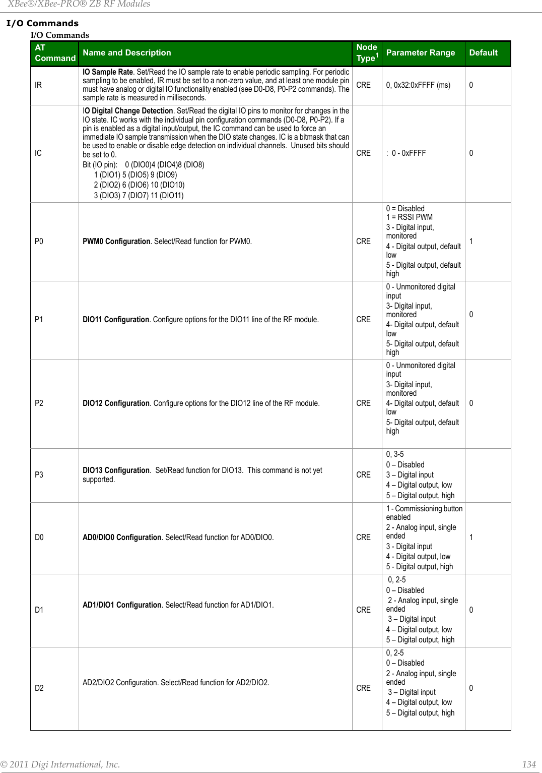
![XBee®/XBee‐PRO®ZBRFModules©2011DigiInternational,Inc. 135D3 AD3/DIO3 Configuration. Select/Read function for AD3/DIO3. CRE0, 2-50 – Disabled2 - Analog input, single ended3 – Digital input4 – Digital output, low5 – Digital output, high0D4 DIO4 Configuration. Select/Read function for DIO4. CRE0, 3-50 – Disabled3 – Digital input4 – Digital output, low5 – Digital output, high0D5 DIO5 Configuration. Configure options for the DIO5 line of the RF module. CRE0 = Disabled1 = Associated indication LED3 = Digital input4 = Digital output, default low5 = Digital output, default high1D8 DIO8 Configuration. Set/Read function for DIO8. This command is not yet supported. CRE0, 3-50 – Disabled3 – Digital input4 – Digital output, low5 – Digital output, highLTAssoc LED Blink Time. Set/Read the Associate LED blink time. If the Associate LED functionality is enabled (D5 command), this value determines the on and off blink times for the LED when the module has joined a network. If LT=0, the default blink rate will be used (500ms coordinator, 250ms router/end device). For all other LT values, LT is measured in 10ms.CRE 0, 0x0A - 0xFF (100 - 2550 ms) 0PRPull-up Resistor. Set/read the bit field that configures the internal pull-up resistor status for the I/O lines. "1" specifies the pull-up resistor is enabled. "0" specifies no pullup.(30k pull-up resistors)Bits:"0 - DIO4 (Pin 11)1 - AD3 / DIO3 (Pin 17)2 - AD2 / DIO2 (Pin 18)3 - AD1 / DIO1 (Pin 19)4 - AD0 / DIO0 (Pin 20)5 - RTS / DIO6 (Pin 16)6 - DTR / Sleep Request / DIO8 (Pin 9)7 - DIN / Config (Pin 3)8 - Associate / DIO5 (Pin 15)9 - On/Sleep / DIO9 (Pin 13)10 - DIO12 (Pin 4)11 - PWM0 / RSSI / DIO10 (Pin 6)12 - PWM1 / DIO11 (Pin 7)13 - CTS / DIO7 (Pin 12)CRE 0 - 0x3FFF 0 - 0x1FFFRP RSSI PWM Timer. Time the RSSI signal will be output on the PWM after the last RF data reception or APS acknowledgment.. When RP = 0xFF, output will always be on. CRE 0 - 0xFF [x 100 ms] 0x28 (40d)%VSupply Voltage. Reads the voltage on the Vcc pin. Scale by 1200/1024 to convert to mV units. For examplee, a %V reading of 0x900 (2304 decimal) represents 2700mV or 2.7OV. CRE -0x-0xFFFF [read only] -V+Voltage Supply Monitoring. The voltage supply threshold is set with the V+ command. If the measured supply voltage falls below or equal to this threshold, the supply voltage will be included in the IO sample set. V+ is set to 0 by default (do not include the supply voltage). Scale mV units by 1024/1200 to convert to internal units. For example, for a 2700mV threshold enter 0x900. Given the operating Vcc ranges for different platforms, and scaling by 1024/1200, the useful parameter ranges are:XBee 2100-3600 mV 0,0x0700-0x0c00PRO 3000-3400 mV, 0,0x0a00-0x0b55S2B 2700-3600 mV, 0,0x0900-0x0c00CRE 0-0xFFFF 0TP Reads the module temperature in Degrees Celsius. Accuracy +/- 7 degrees. 1° C = 0x0001 and -1° C = 0xFFFF. Command is only available in PRO S2B. CRE 0x0-0xFFFF -I/OCommandsATCommand Name and Description Node Type1Parameter Range Default](https://usermanual.wiki/Digi/XBEEPRO2.Revised-Used-Manual/User-Guide-1544897-Page-135.png)
![XBee®/XBee‐PRO®ZBRFModules©2011DigiInternational,Inc. 136Diagnostics1.Nodetypesthatsupportthecommand:C=Coordinator,R=Router,E=EndDeviceAT Command Options1.Nodetypesthatsupportthecommand:C=Coordinator,R=Router,E=EndDeviceDiagnosticsCommandsATCommand Name and Description Node Type1Parameter Range DefaultVRFirmware Version. Read firmware version of the module.The firmware version returns 4 hexadecimal values (2 bytes) "ABCD". Digits ABC are the main release number and D is the revision number from the main release. "B" is a variant designator.XBee and XBee-PRO ZB modules return:0x2xxx versions.XBee and XBee-PRO ZNet modules return:0x1xxx versions. ZNet firmware is not compatible with ZB firmware.CRE 0 - 0xFFFF [read-only] Factory-setHVHardware Version. Read the hardware version of the module.version of the module. This command can be used to distinguish among different hardware platforms. The upper byte returns a value that is unique to each module type. The lower byte indicates the hardware revision.XBee ZB and XBee ZNet modules return the following (hexadecimal) values:0x19xx - XBee module0x1Axx - XBee-PRO moduleCRE 0 - 0xFFFF [read-only] Factory-setAIAssociation Indication. Read information regarding last node join request:0x00 - Successfully formed or joined a network. (Coordinators form a network, routers and end devices join a network.)0x21 - Scan found no PANs0x22 - Scan found no valid PANs based on current SC and ID settings0x23 - Valid Coordinator or Routers found, but they are not allowing joining (NJ expired)0x24 - No joinable beacons were found0x25 - Unexpected state, node should not be attempting to join at this time0x27 - Node Joining attempt failed (typically due to incompatible security settings)0x2A - Coordinator Start attempt failed‘0x2B - Checking for an existing coordinator0x2C - Attempt to leave the network failed0xAB - Attempted to join a device that did not respond.0xAC - Secure join error - network security key received unsecured0xAD - Secure join error - network security key not received0xAF - Secure join error - joining device does not have the right preconfigured link key0xFF - Scanning for a ZigBee network (routers and end devices)Note: New non-zero AI values may be added in later firmware versions. Applications should read AI until it returns 0x00, indicating a successful startup (coordinator) or join (routers and end devices)CRE 0 - 0xFF[read-only] --ATCommandOptionsCommandsATCommand Name and Description Node Type1Parameter Range DefaultCTCommand Mode Timeout. Set/Read the period of inactivity (no valid commands received) after which the RF module automatically exits AT Command Mode and returns to Idle Mode.CRE 2 - 0x028F [x 100 ms] 0x64 (100d)CN Exit Command Mode. Explicitly exit the module from AT Command Mode. CRE -- --GTGuard Times. Set required period of silence before and after the Command Sequence Characters of the AT Command Mode Sequence (GT + CC + GT). The period of silence is used to prevent inadvertent entrance into AT Command Mode.CRE 1 - 0x0CE4 [x 1 ms](max of 3.3 decimal sec)0x3E8(1000d)CCCommand Sequence Character. Set/Read the ASCII character value to be used between Guard Times of the AT Command Mode Sequence (GT + CC + GT). The AT Command Mode Sequence enters the RF module into AT Command Mode. The CC command is only supported when using AT firmware: 20xx (AT coordinator), 22xx (AT router), 28xx (AT end device).CRE 0 - 0xFF 0x2B (‘+’ ASCII)](https://usermanual.wiki/Digi/XBEEPRO2.Revised-Used-Manual/User-Guide-1544897-Page-136.png)
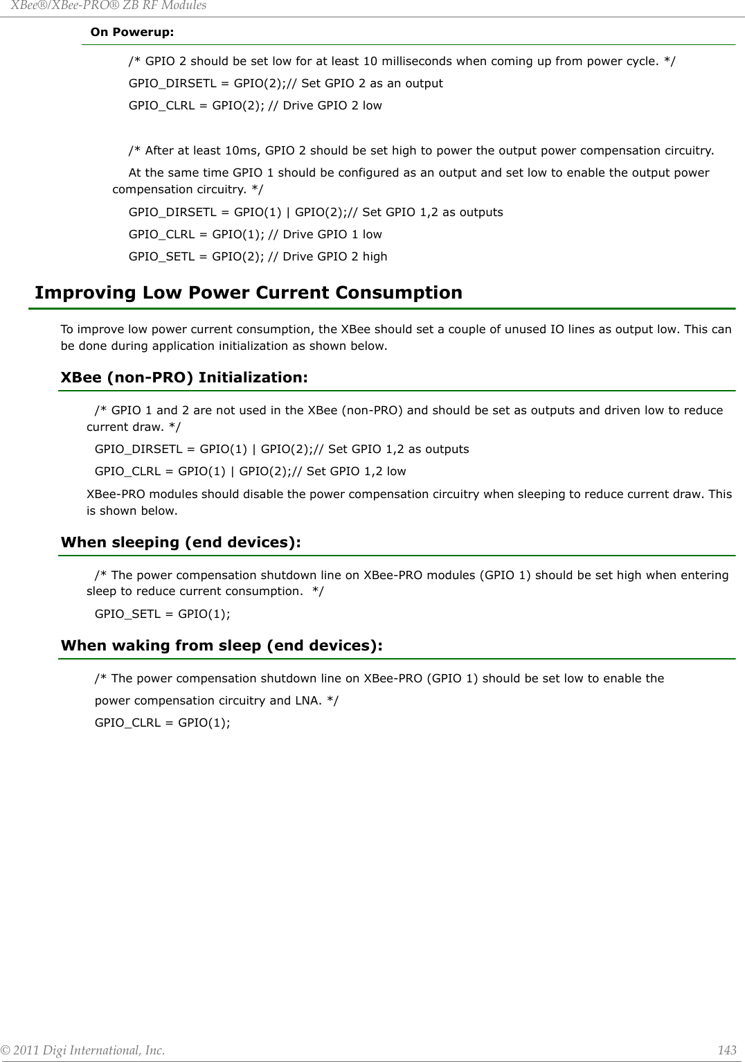
![XBee®/XBee‐PRO®ZBRFModules©2011DigiInternational,Inc. 142Example 1The following code enables GPIO 0, 1, 2, 3, 9, 10, 11, and 12 and maintains all other GPIO_CFG bits.int16u x;x = GPIO_CFG;x &= (0xFF0F); // Clear bits 4 - 7GPIO_CFG = x;Example 2The following code enables GPIO 0, 1, 2, 3, and 12 and maintains all other GPIO_CFG bits.int16u x;x = GPIO_CFG;x &= (0xFF0F); // Clear bits 4 - 7x |= 0x0070; // Set bits 4 - 7 to 0111 as shown in the table above. GPIO_CFG = x;Detecting XBee vs. XBee-PROFor some applications, it may be necessary to determine if the code is running on an XBee or an XBee-PRO device. The GPIO1 pin on the EM250 is used to identify the module type (see table 1-03 in chapter 1). GPIO1 is connected to ground on the XBee module. The following code could be used to determine if a module is an XBee or XBee-PRO:GPIO_DIRCLRL = GPIO(1);// Set GPIO1 as an inputGPIO_PUL |= GPIO(1);// Enable GPIO1 pullup resistorModuleIsXBeePro = (GPIO_INL & GPIO(1));//ModuleIsXBeePro > 0 if XBee-PRO, =0 if non-PRO. Ensuring Optimal Output PowerXBee modules manufactured before February 2008 had an incorrect configuration setting that caused the default output power mode to be set incorrectly. Digi's ZB and ZNet firmware compensate for this by setting the output power mode in the application firmware.Custom applications should call the emberSetTxPowerMode() function to set the output power mode as shown below:XBee ApplicationsemberSetTxPowerMode(EMBER_TX_POWER_MODE_DEFAULT); or emberSetTxPowerMode(EMBER_TX_POWER_MODE_BOOST);XBee-PRO Applications:emberSetTxPowerMode(EMBER_TX_POWER_MODE_ALTERNATE); oremberSetTxPowerMode(EMBER_TX_POWER_MODE_BOOST_AND_ALTERNATE);XBee-PRO modules must also set a couple of IO lines to enable output power compensation. This is shown below. Once the IO lines are initialized (after powerup), the XBee will enable the power amplifier and LNA as needed.GPIO_CFG[7:4]Enabled Functionality Enabled Functionality0000 GPIO 0, 1, 2, 3, 9, 10, 11, 120111 0111GPIO 0, 1, 2, 3, 121010 GPIO 0, 1, 2, 31101 GPIO 0, 1, 2, 3, 11, 12](https://usermanual.wiki/Digi/XBEEPRO2.Revised-Used-Manual/User-Guide-1544897-Page-142.png)
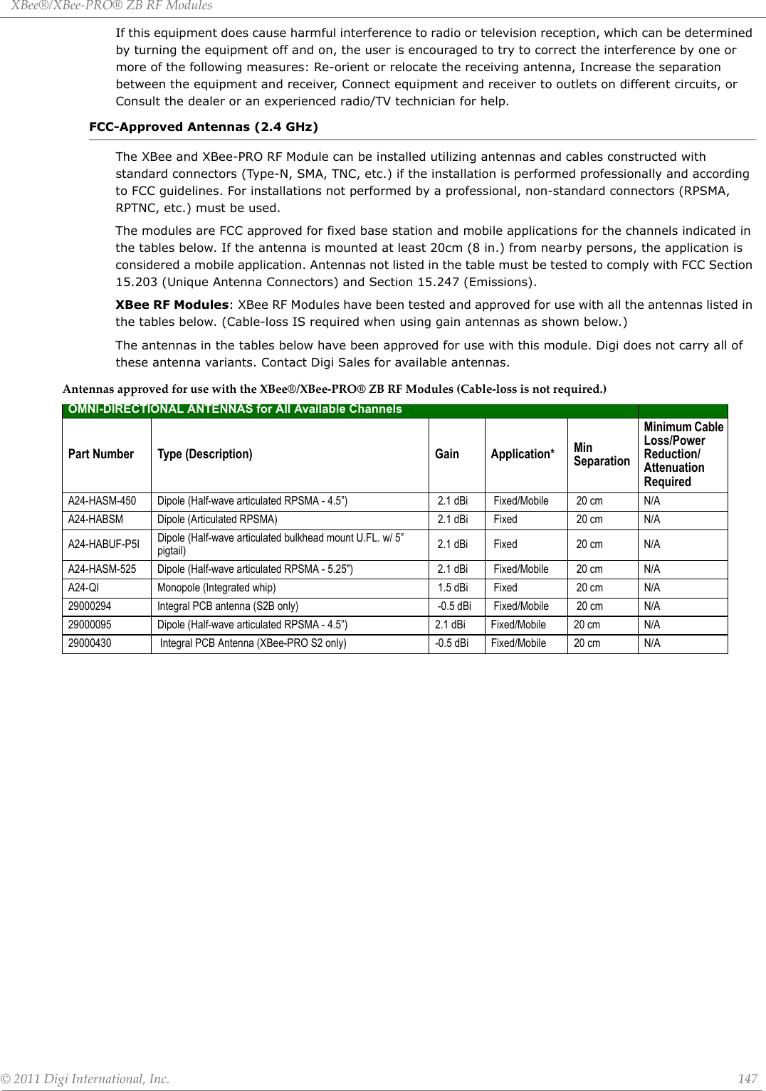
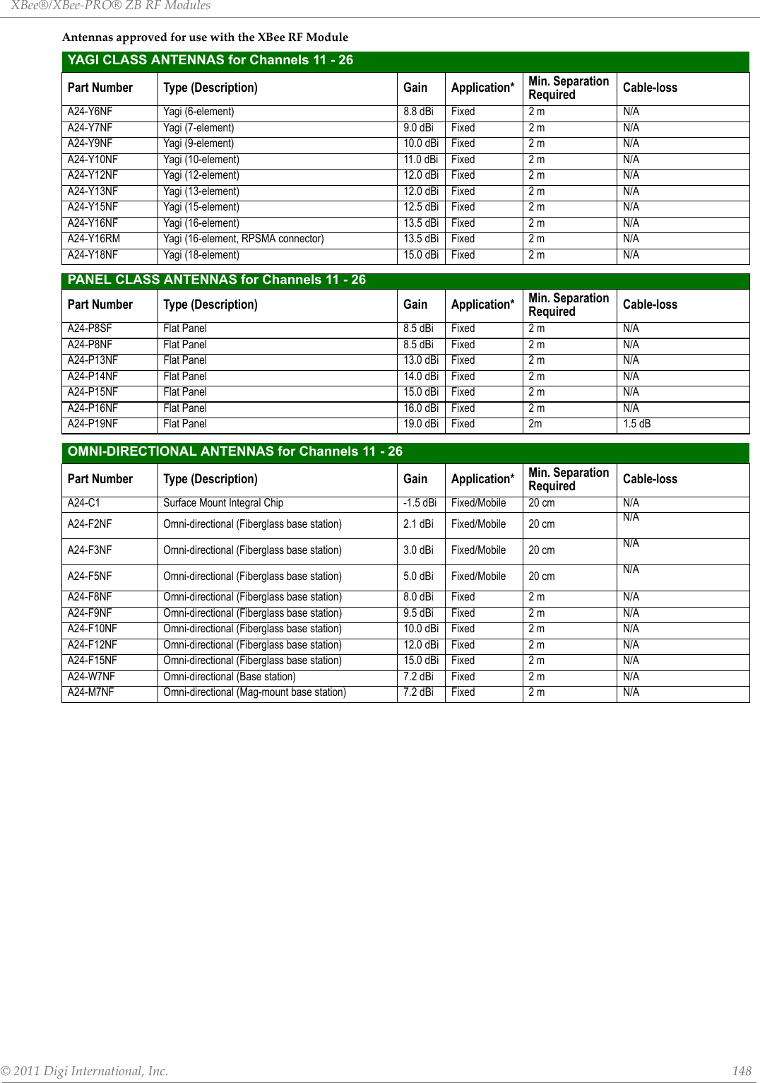
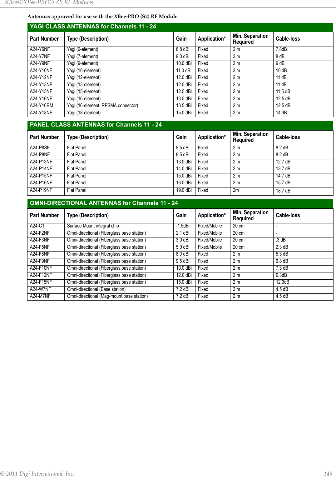
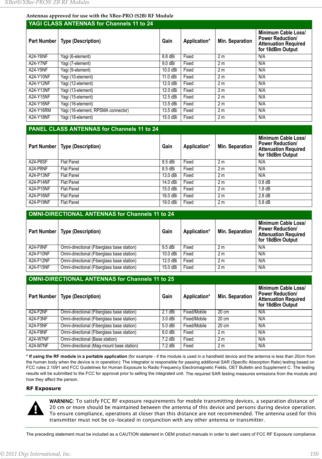
![©2011DigiInternational,Inc. 146AppendixB:AgencyCertificationsUnited States FCCThe XBee RF Module complies with Part 15 of the FCC rules and regulations. Compliance with the labeling requirements, FCC notices and antenna usage guidelines is required.To fulfill FCC Certification, the OEM must comply with the following regulations:1.The system integrator must ensure that the text on the external label provided with this device is placed on the outside of the final product.2.XBee RF Module may only be used with antennas that have been tested and approved for use with this module [refer to the antenna tables in this section].OEM Labeling RequirementsWARNING: The Original Equipment Manufacturer (OEM) must ensure that FCC labeling requirements are met. This includes a clearly visible label on the outside of the final product enclosure that displays the contents shown in the figure below. Required FCC Label for OEM products containing the XBee RF Module Required FCC Label for OEM products containing the XBee PRO (S2) RF Module Required FCC Label for OEM products containing the XBee PRO (S2B) RF Module FCC NoticesIMPORTANT: The XBee and XBee PRO RF Module have been certified by the FCC for use with other products without any further certification (as per FCC section 2.1091). Modifications not expressly approved by Digi could void the user's authority to operate the equipment.IMPORTANT: OEMs must test final product to comply with unintentional radiators (FCC section 15.107 & 15.109) before declaring compliance of their final product to Part 15 of the FCC Rules.IMPORTANT: The RF module has been certified for remote and base radio applications. If the module will be used for portable applications, the device must undergo SAR testing.This equipment has been tested and found to comply with the limits for a Class B digital device, pursuant to Part 15 of the FCC Rules. These limits are designed to provide reasonable protection against harmful interference in a residential installation. This equipment generates, uses and can radiate radio frequency energy and, if not installed and used in accordance with the instructions, may cause harmful interference to radio communications. However, there is no guarantee that interference will not occur in a particular installation. Contains FCC ID: OUR-XBEE2*The enclosed device complies with Part 15 of the FCC Rules. Operation is subject to the following two conditions: (i.) this device may not cause harmful interference and (ii.) this device must accept any interference received, including interference that may cause undesired operation.Contains FCC ID:MCQ-XBEEPRO2*The enclosed device complies with Part 15 of the FCC Rules. Operation is subject to the following two conditions: (i.) this device may not cause harmful interference and (ii.) this device must accept any interference received, including interference that may cause undesired operation.Contains FCC ID:MCQ-PROS2B*The enclosed device complies with Part 15 of the FCC Rules. Operation is subject to the following two conditions: (i.) this device may not cause harmful interference and (ii.) this device must accept any interference received, including interference that may cause undesired operation.](https://usermanual.wiki/Digi/XBEEPRO2.Revised-Used-Manual/User-Guide-1544897-Page-146.png)