Digi XBSX XBee SX RF Module User Manual
Digi International Inc XBee SX RF Module
UserManual.wiki
>
Digi
>
XBSX User Manual
User Manual
Navigation menu
Upload a User Manual
Namespaces
Wiki Guide
HTML
PDF
Info
Views
User Manual
Discussion / Help
Navigation
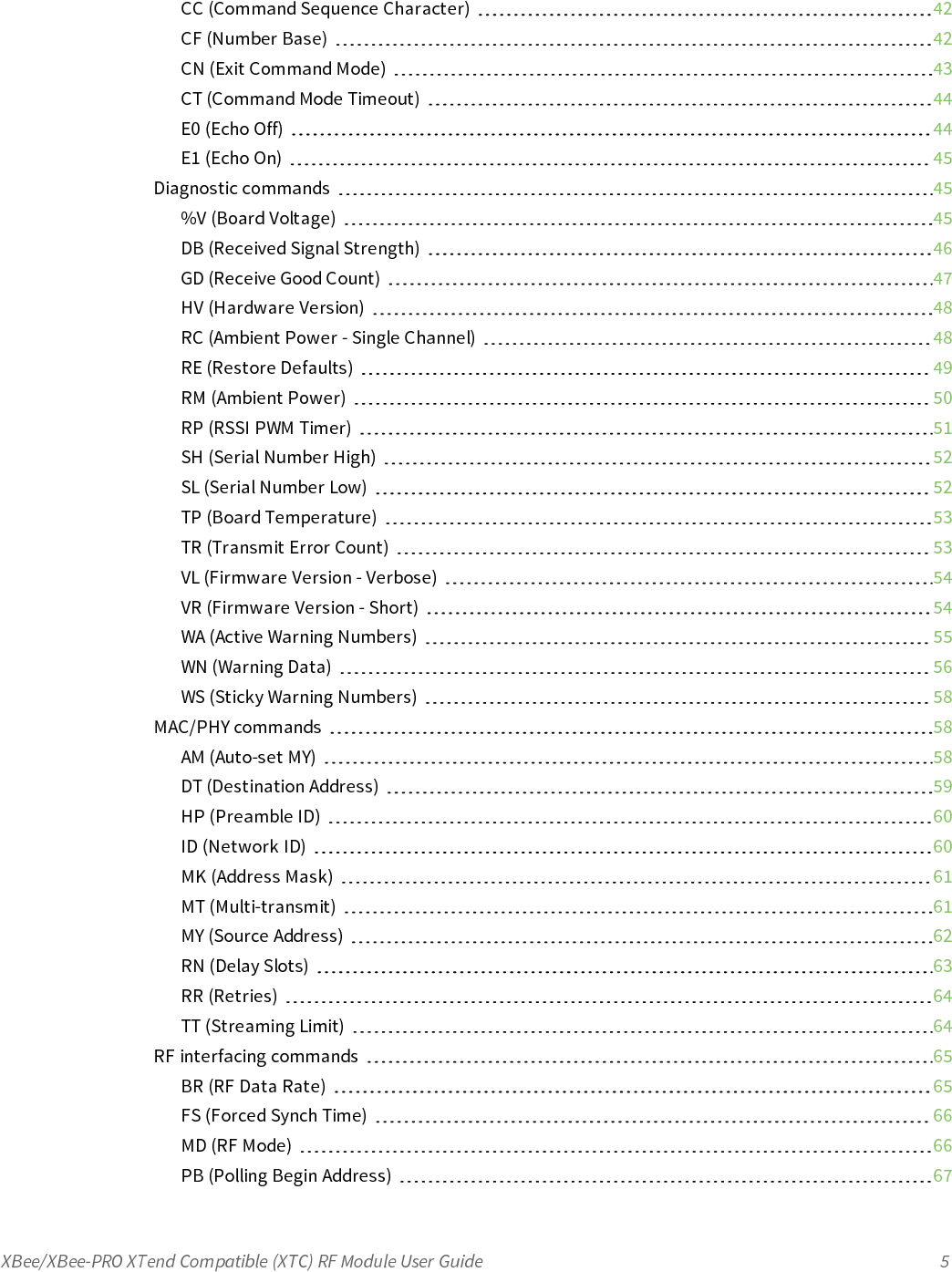


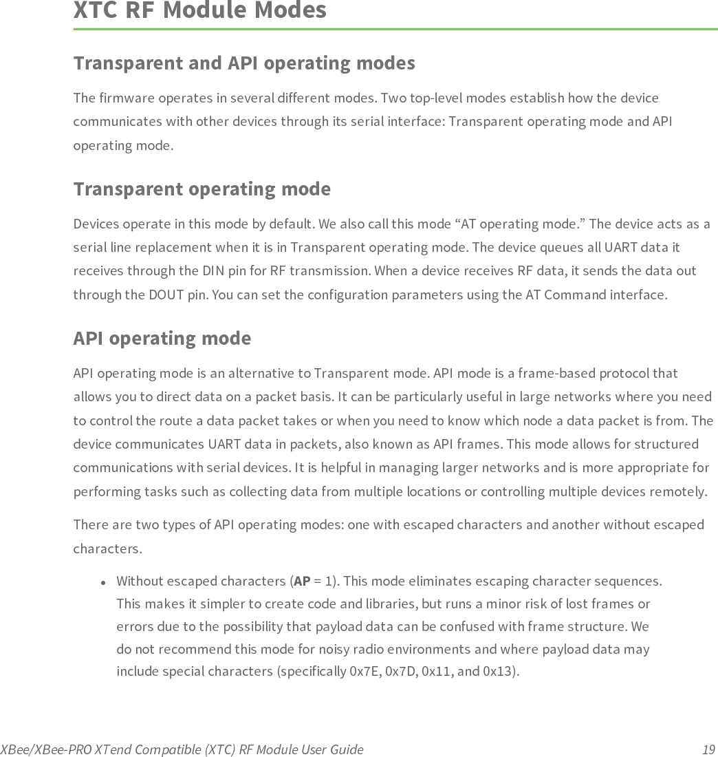
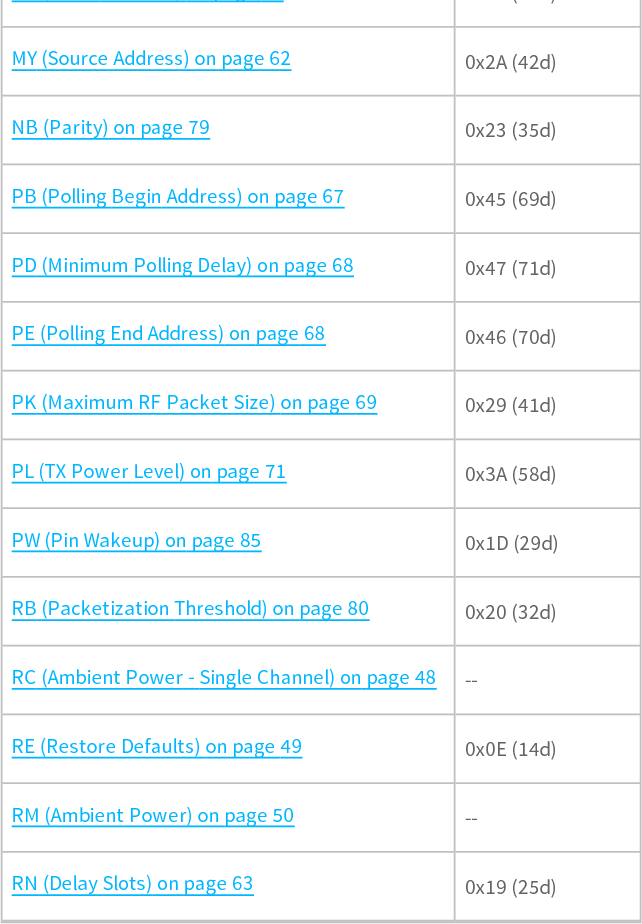
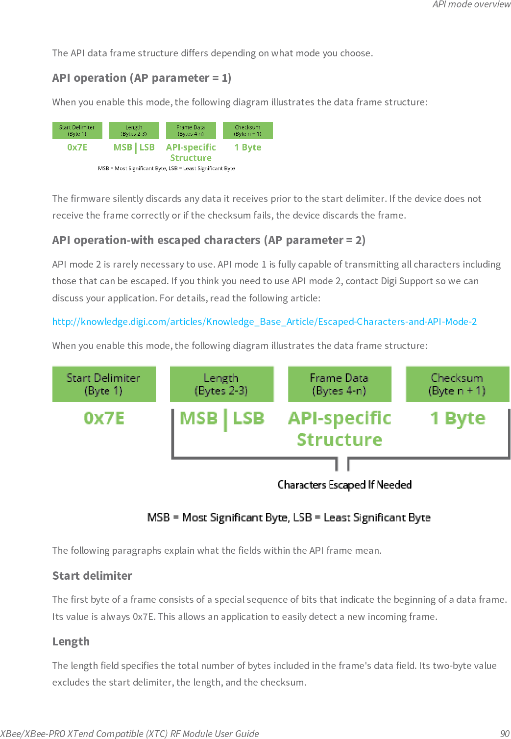
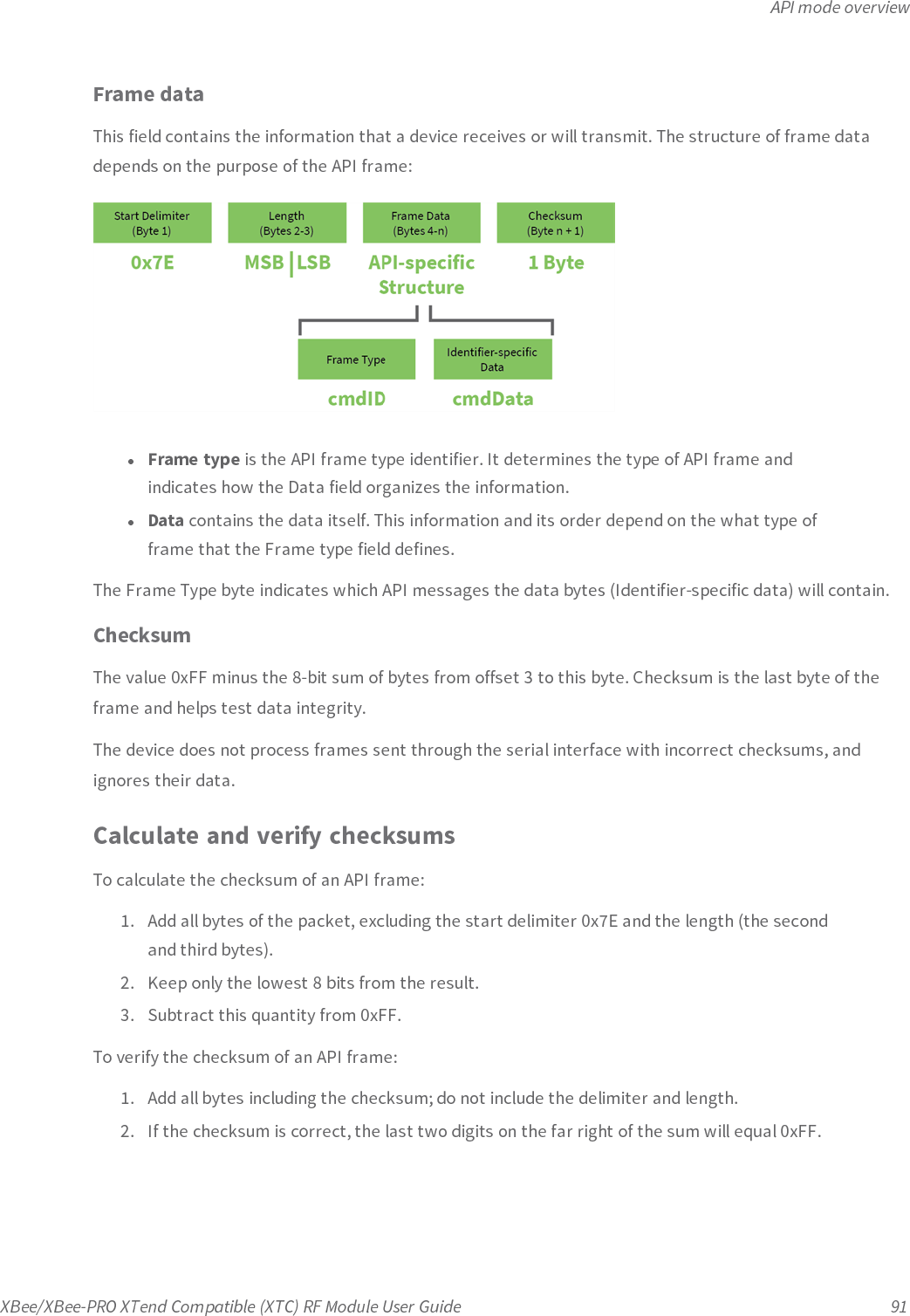
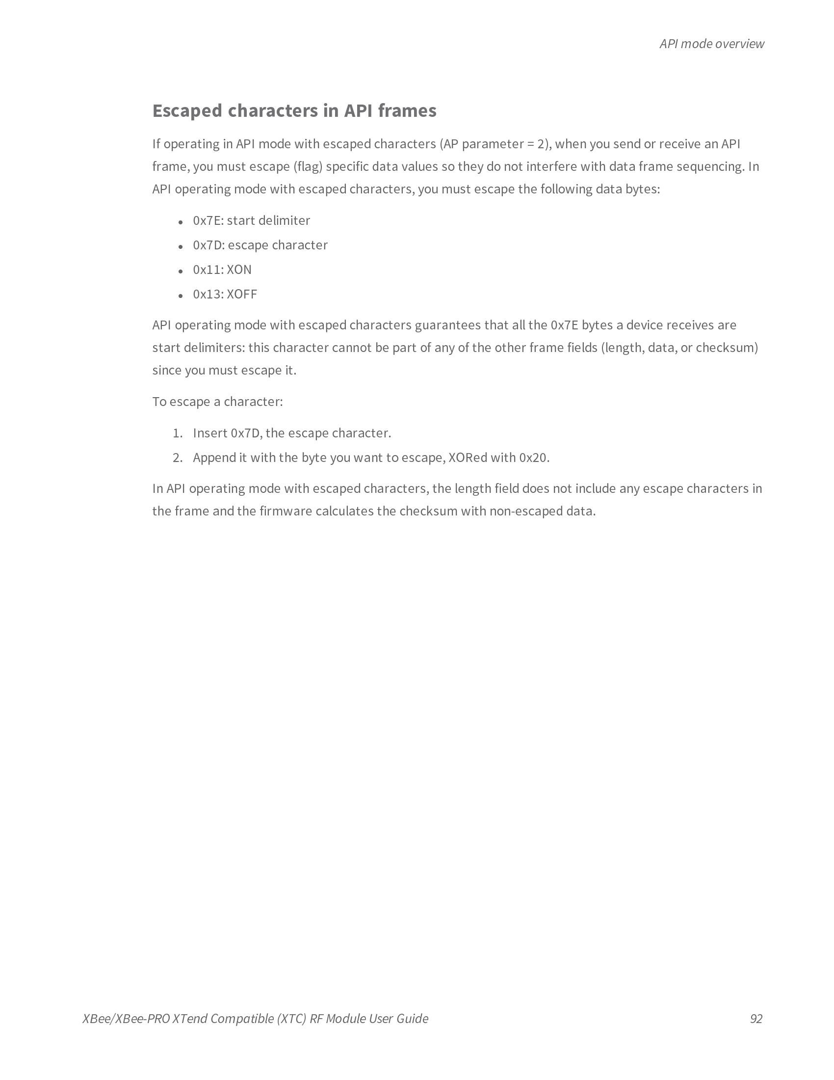
![Command mode optionsXBee/XBee-PRO XTend Compatible (XTC) RF Module User Guide 41AT command Binary commandWS (Sticky Warning Numbers) on page 58 --Command mode optionsThe following AT commands are Command mode option commands.AT (Guard Time After)Sets or reads the time-of-silence that follows the CC (Command Sequence Character) of the Commandmode sequence (BT + CC + AT). By default, one second must elapse before and after the commandsequence character.The times-of-silence surrounding the Command Sequence Character prevent the device frominadvertently entering Command mode.Binary command0x05 (5 decimal)Command typeCommand mode optionsParameter range2 - (ST-3) up to 0x1770 [x 100 ms]Default0xA (1 second)Bytes returned2BT (Guard Time Before)Sets the DI pin silence time that must precede the Command Sequence Character (CC command) of theCommand mode sequence. For more information about the Command mode sequence, see EnterCommand mode on page 21.Binary command0x04 (4 decimal)](https://usermanual.wiki/Digi/XBSX/User-Guide-2864252-Page-41.png)
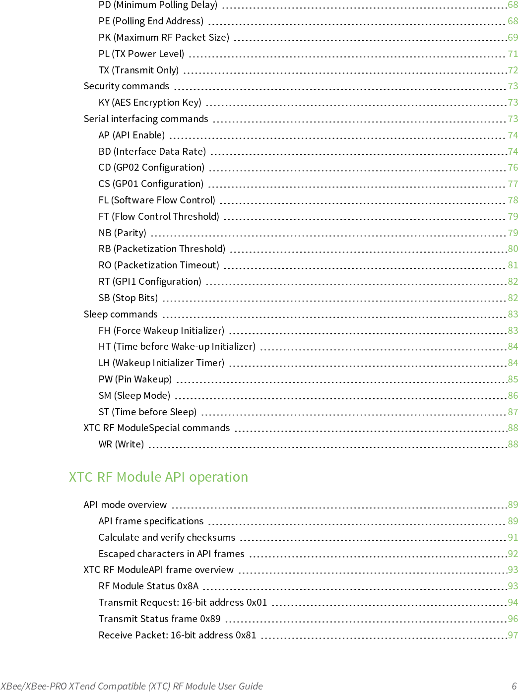
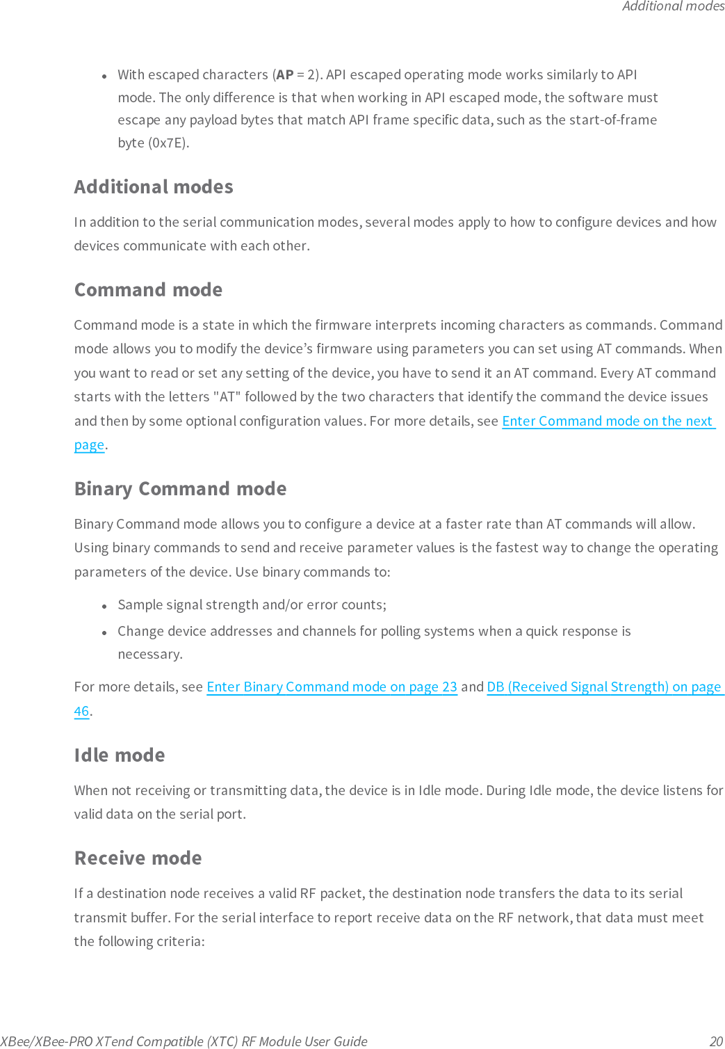
![Command mode optionsXBee/XBee-PRO XTend Compatible (XTC) RF Module User Guide 42Command typeCommand mode optionsParameter range0 - 0x1770 [x 100ms]Default0x0A (1 second)Bytes returned2CC (Command Sequence Character)The ASCII character value you use to enter Command mode. Use CC to set or read the character usedbetween guard times of the Command mode sequence (BT + CC + AT). This sequence enters the deviceinto Command mode so that device recognizes data entering it from the host as commands instead ofpayload data.Binary command0x13 (19 decimal)Command typeCommand mode optionsParameter range0x20 - 0x7FDefault0x2B (ASCII “+”)Bytes returned1CF (Number Base)Sets or reads the command formatting setting.The firmware always enters and reads the following commands in hex, no matter what the CF setting is:](https://usermanual.wiki/Digi/XBSX/User-Guide-2864252-Page-42.png)
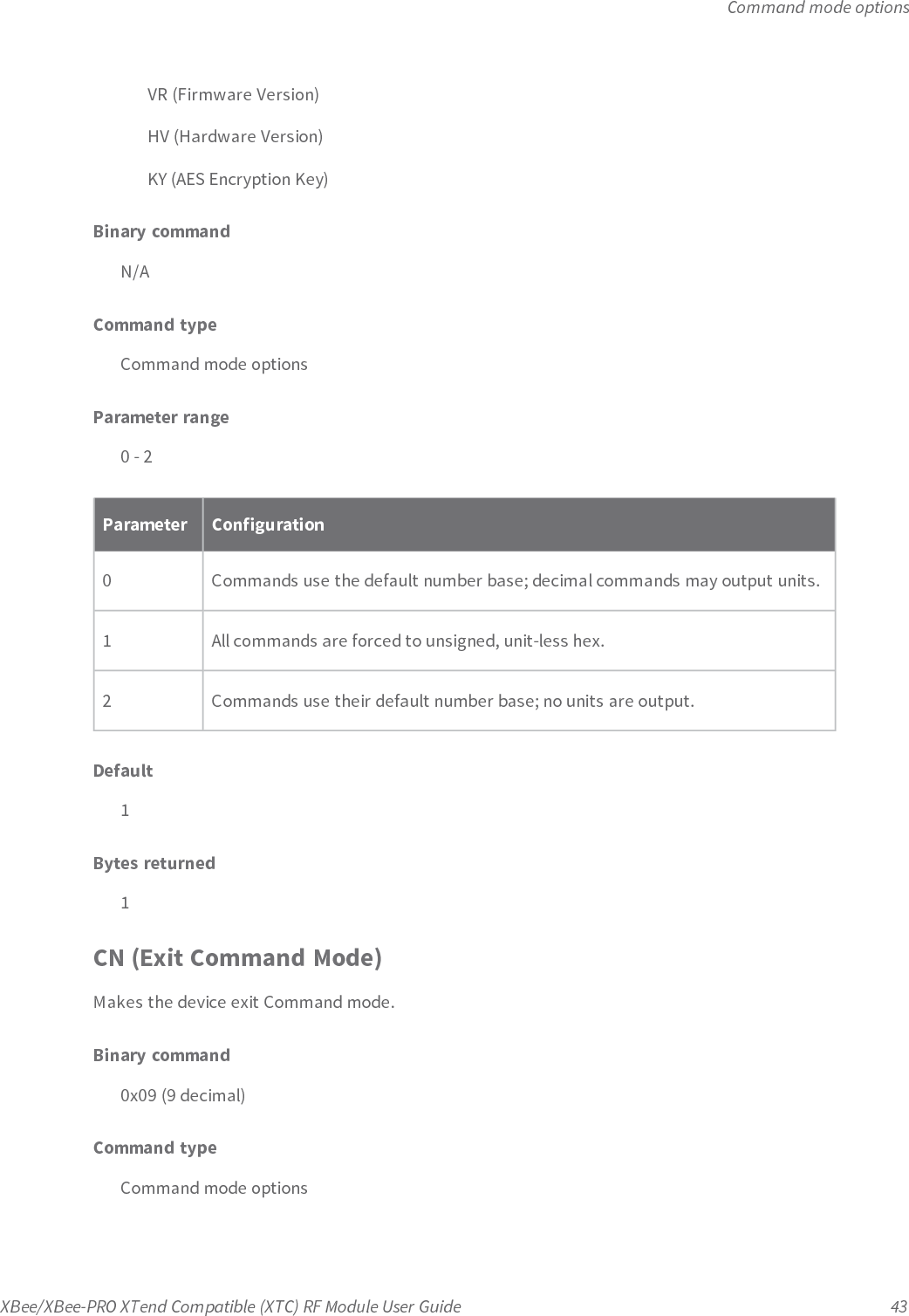
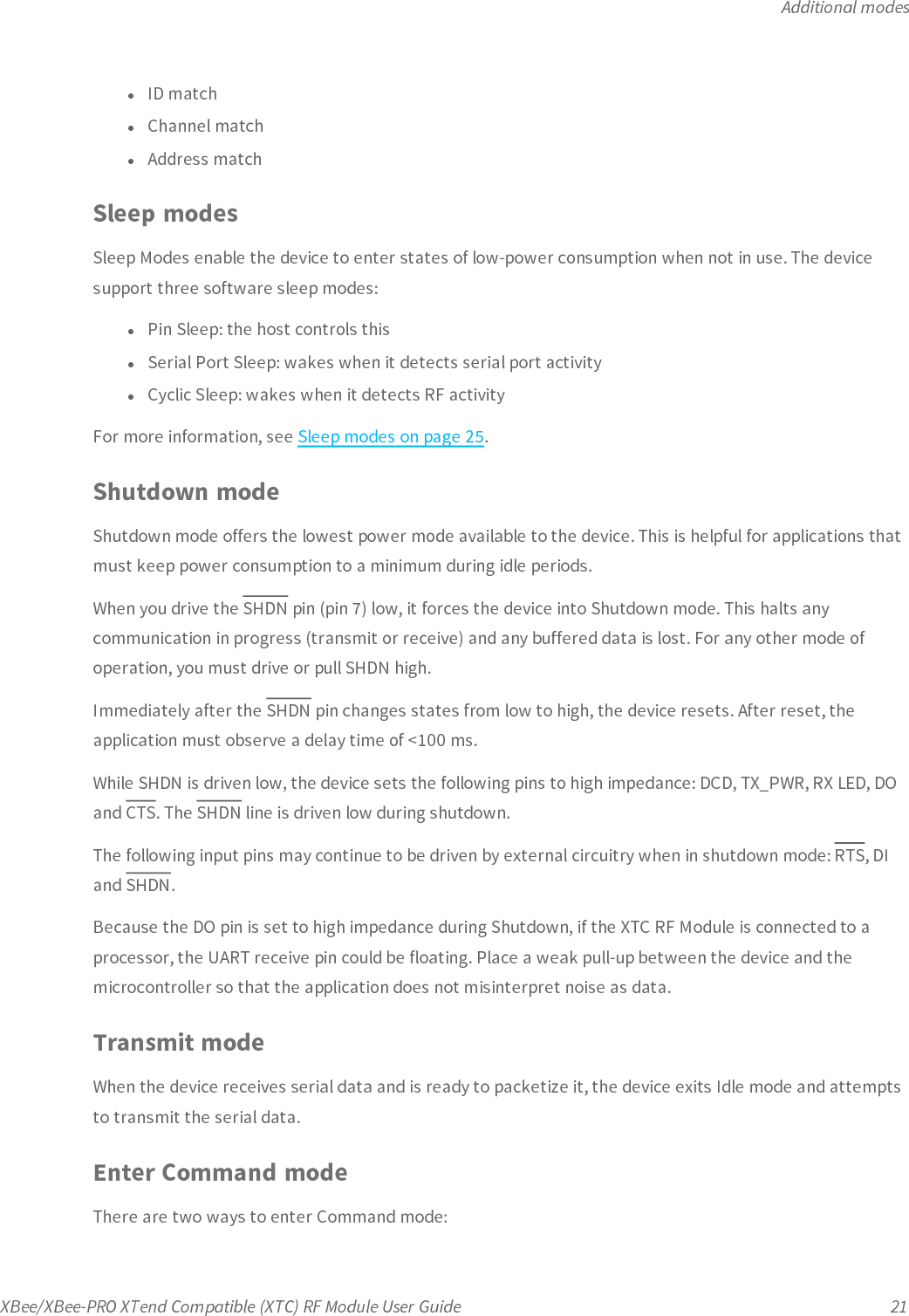
![Command mode optionsXBee/XBee-PRO XTend Compatible (XTC) RF Module User Guide 44Parameter rangeN/ADefaultN/ABytes returnedN/ACT (Command Mode Timeout)Set or read the Command mode timeout parameter. If a device does not receive any valid commandswithin this time period, it returns to Idle mode from Command mode.Use the CN (Exit Command mode) command to exit Command mode manually.Binary command0x06 (6 decimal)Command typeCommand mode optionsParameter range2 - 0x53E2 [x 100 milliseconds]Default0xC8 (20 seconds)Bytes returned2E0 (Echo Off)Turns off the character echo in Command mode.By default, echo is off.Binary command0x0A (10 decimal)](https://usermanual.wiki/Digi/XBSX/User-Guide-2864252-Page-44.png)
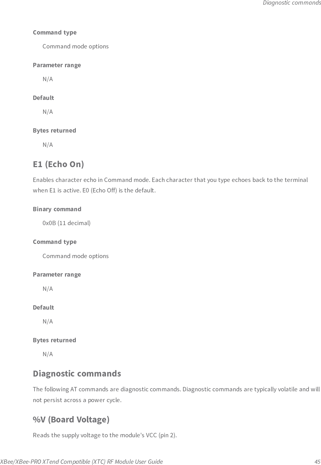
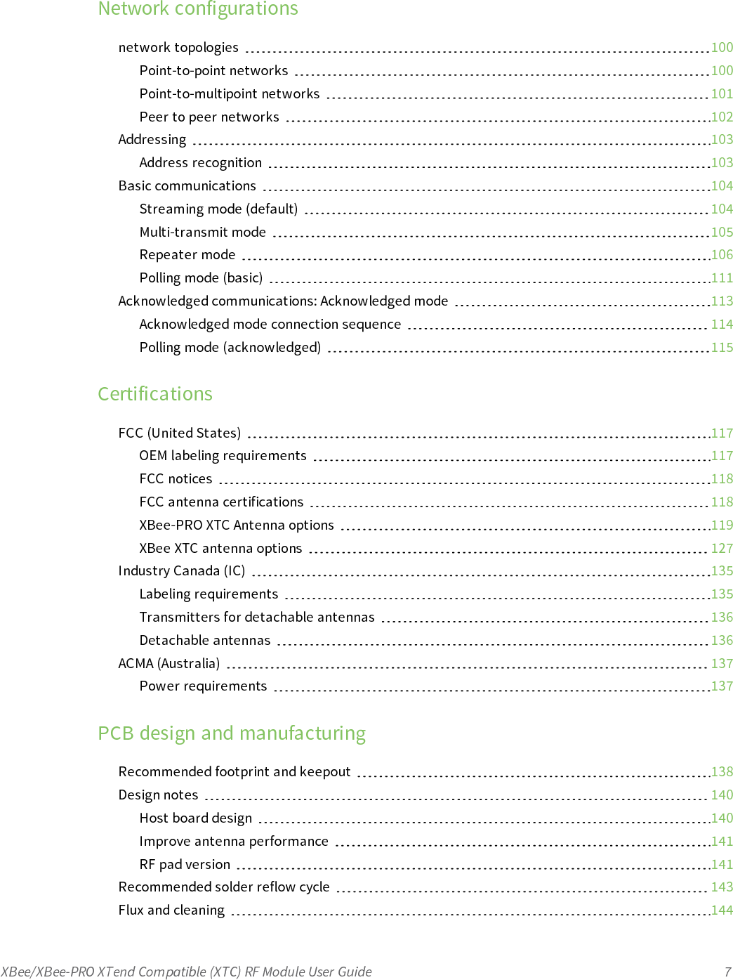
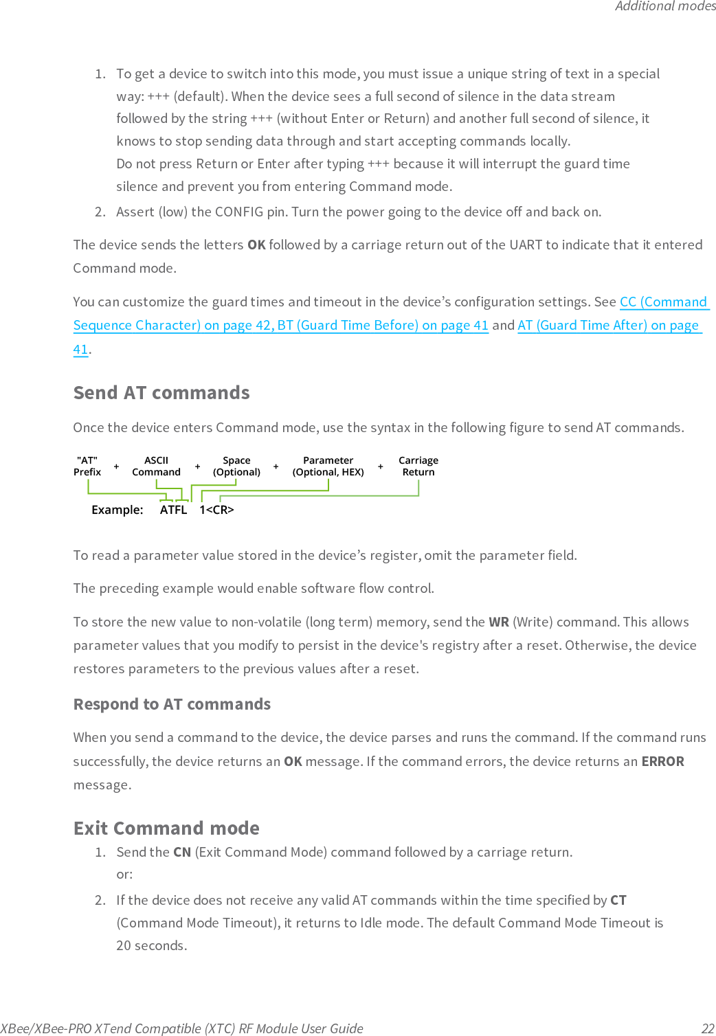
![Diagnostic commandsXBee/XBee-PRO XTend Compatible (XTC) RF Module User Guide 49-78 (when CF = 2)Binary commandN/AParameter range(read-only): 0 - 0x31 [dBm]DefaultN/ABytes returned1RE (Restore Defaults)Restore device parameters to factory defaults.RE does not cause the device to store default values to non-volatile (persistent) memory. You must sendthe WR command prior to power-down or reset to save the default settings in the device's non-volatilememory.Binary command0x0E (14 decimal)Command typeDiagnosticsParameter rangeN/ADefaultN/ABytes returnedN/A](https://usermanual.wiki/Digi/XBSX/User-Guide-2864252-Page-49.png)
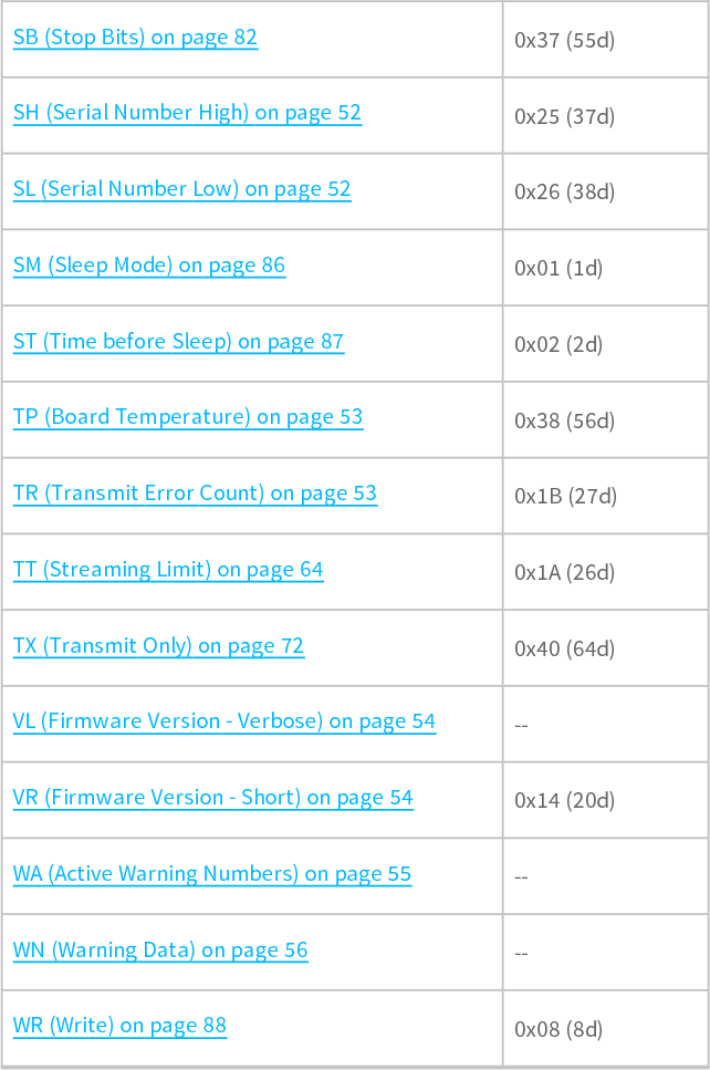
![Diagnostic commandsXBee/XBee-PRO XTend Compatible (XTC) RF Module User Guide 52Parameter range0 - 0xFF [x 100 milliseconds]Default0x20 (3.2 seconds)Bytes returned1SH (Serial Number High)Sets or reads the device's serial number high word.Binary command0x25 (37 decimal)Command typeDiagnosticsParameter range0 - 0xFFFFDefaultVariesBytes returned2SL (Serial Number Low)Sets or reads the serial number low word of the device.Binary command0x26 (38 decimal)Command typeDiagnostics](https://usermanual.wiki/Digi/XBSX/User-Guide-2864252-Page-52.png)
![MAC/PHY commandsXBee/XBee-PRO XTend Compatible (XTC) RF Module User Guide 63Default0xFFFF (Disabled - DT (Destination Address) parameter serves as both source and destinationaddress).Bytes returned2RN (Delay Slots)Sets or reads the time delay that the transmitting device inserts before attempting to resend a packet. Ifthe transmitting device fails to receive an acknowledgment after sending a packet, it inserts a randomnumber of delay slots (ranging from 0 to (RN minus 1)) before attempting to resend the packet. Each delayslot is 5 msec when BR = 1 and 54 msec when BR = 0.If two devices attempt to transmit at the same time, the random time delay after packet failure onlyallows one device to transmit the packet successfully, while the other device waits until the channel isavailable for RF transmission.RN is only applicable if:lYou enable retries using the RR command, orlYou insert forced delays into a transmission using the TT commandBinary command0x19 (25 decimal)Command typeMAC/PHYParameter range0 - 0xFF [38 ms delay slots]Default0 (no delay slots inserted)Bytes returned1](https://usermanual.wiki/Digi/XBSX/User-Guide-2864252-Page-63.png)
![RF interfacing commandsXBee/XBee-PRO XTend Compatible (XTC) RF Module User Guide 65Command typeMAC/PHYParameter range0 - 0xFFFF [bytes]Default0Bytes returned2RF interfacing commandsThe following AT commands are RF interfacing commands.BR (RF Data Rate)Sets and reads the device's RF data rate (the rate that the device transmits RF data over-the-air).Binary command0x39 (57 decimal)Parameter range0 - 1Parameter RF data rate0 10 kb/s1 125 kb/sDefault1Bytes returned1](https://usermanual.wiki/Digi/XBSX/User-Guide-2864252-Page-65.png)
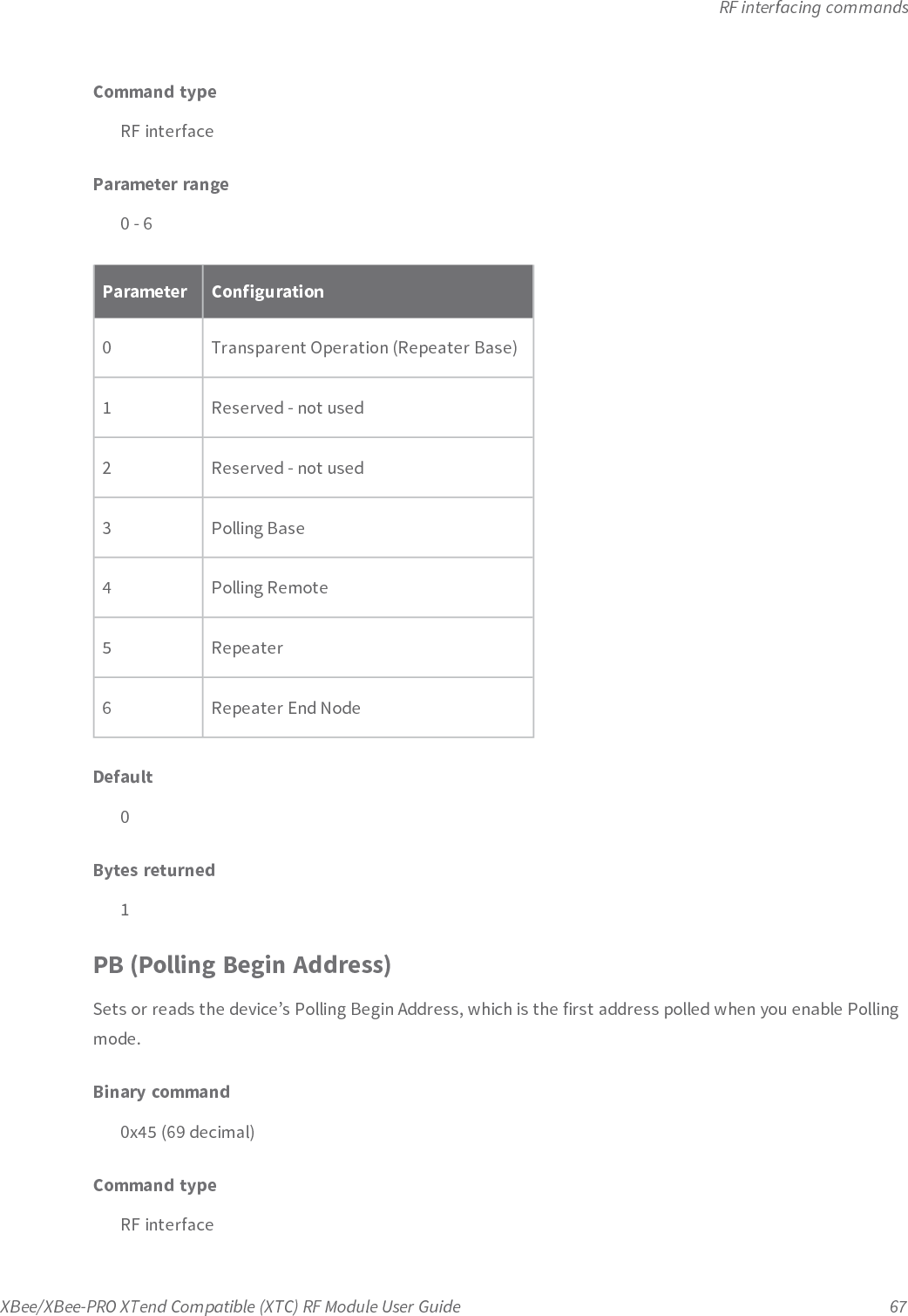
![RF interfacing commandsXBee/XBee-PRO XTend Compatible (XTC) RF Module User Guide 66FS (Forced Synch Time)The FS command only applies to streaming data. Normally, only the first packet of a continuous streamcontains the full RF initializer. The RF devices then remain synchronized for subsequent packets of thestream.You can use this parameter to periodically force an RF initializer during such streaming. Any break in UARTcharacter reception that is long enough to drain the DI buffer and cause a pause in RF data transmissionalso causes the firmware to insert an RF initializer on the next transmission.Binary command0x3F (63 decimal)Command typeRF interfacingParameter range0 - 0xFFFF[x 10 milliseconds]Default0Bytes returned2MD (RF Mode)Sets or reads the settings that enable the Polling and Repeater modes on the device.Polling Mode: a Polling Base is responsible for polling remotes. A Polling Remote requires a poll from aPolling Base in order to transmit.Repeater Mode: a Repeater re-sends RF data unless the transmission is addressed to it or if it has alreadydetected the transmission. A Repeater End Node handles repeated messages, but will not repeat themessage over-the-air.For more information, see Basic communications on page 104.Binary command0x31 (49 decimal)](https://usermanual.wiki/Digi/XBSX/User-Guide-2864252-Page-66.png)
![RF interfacing commandsXBee/XBee-PRO XTend Compatible (XTC) RF Module User Guide 68Parameter range0 - 0xFFFFDefault0Bytes returned2PD (Minimum Polling Delay)Sets or reads the Polling Delay (Base, MD = 3) or Polling Timeout (Remote, MD = 4).Polling Delay (Base) is the time between polling cycles. The Polling Base starts the polling cycle aftersending the first poll. After the polling cycle completes, the timer restarts.Polling Timeout (Remote) is the amount of time the remote device holds data from the serial port beforediscarding it. The device transmits data entered within the PD time of the poll and does not discard it.Binary command0x47 (71 decimal)Command typeRF interfaceParameter range0 - 0xFFFF (Base: [x 1ms], Remote: [x 10ms])Default0x64Bytes returned2PE (Polling End Address)Sets or reads the device’s Polling End Address; which is the last address polled when you enable Pollingmode.](https://usermanual.wiki/Digi/XBSX/User-Guide-2864252-Page-68.png)
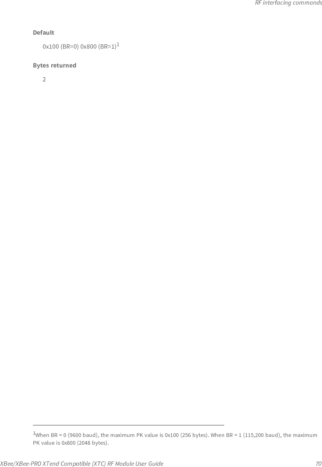
![RF interfacing commandsXBee/XBee-PRO XTend Compatible (XTC) RF Module User Guide 69Binary command0x46 (70 decimal)Command typeRF interfaceParameter range0 - 0xFFFFDefault0Bytes returned2PK (Maximum RF Packet Size)Sets or reads the maximum size of RF packets that a device in Transparent operating mode (AP = 0)transmits. You can use the maximum packet size along with the RB and RO parameters to implicitly setthe channel dwell time.If you set PK above 256 and subsequently change BR to 0, PK lowers to 256 and issues a warning. Formore information, see BR (RF Data Rate) on page 65 and WN (Warning Data) on page 56.Changes to the PK parameter may have a secondary effect on the RB (Packetization Threshold)parameter. RB must always be less than or equal to PK. If you change PK to a value that is less than thecurrent value of RB, the RB value lowers to be equal to PK.Binary command0x29 (41 decimal)Command typeRF interfacingParameter range1 - 0x800 [Bytes]](https://usermanual.wiki/Digi/XBSX/User-Guide-2864252-Page-69.png)
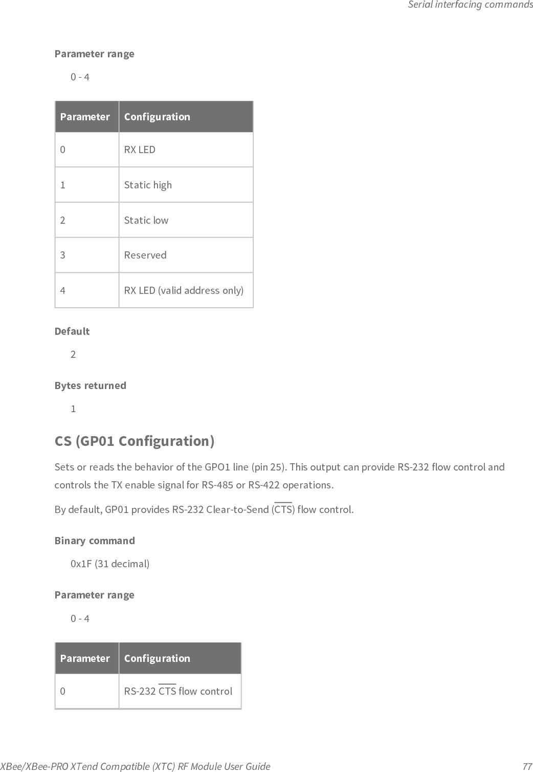
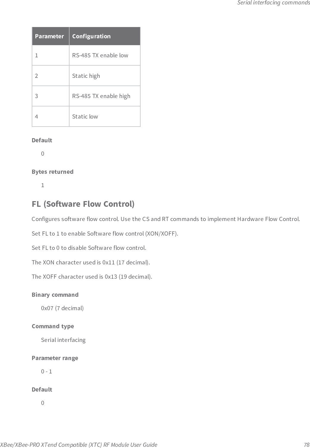
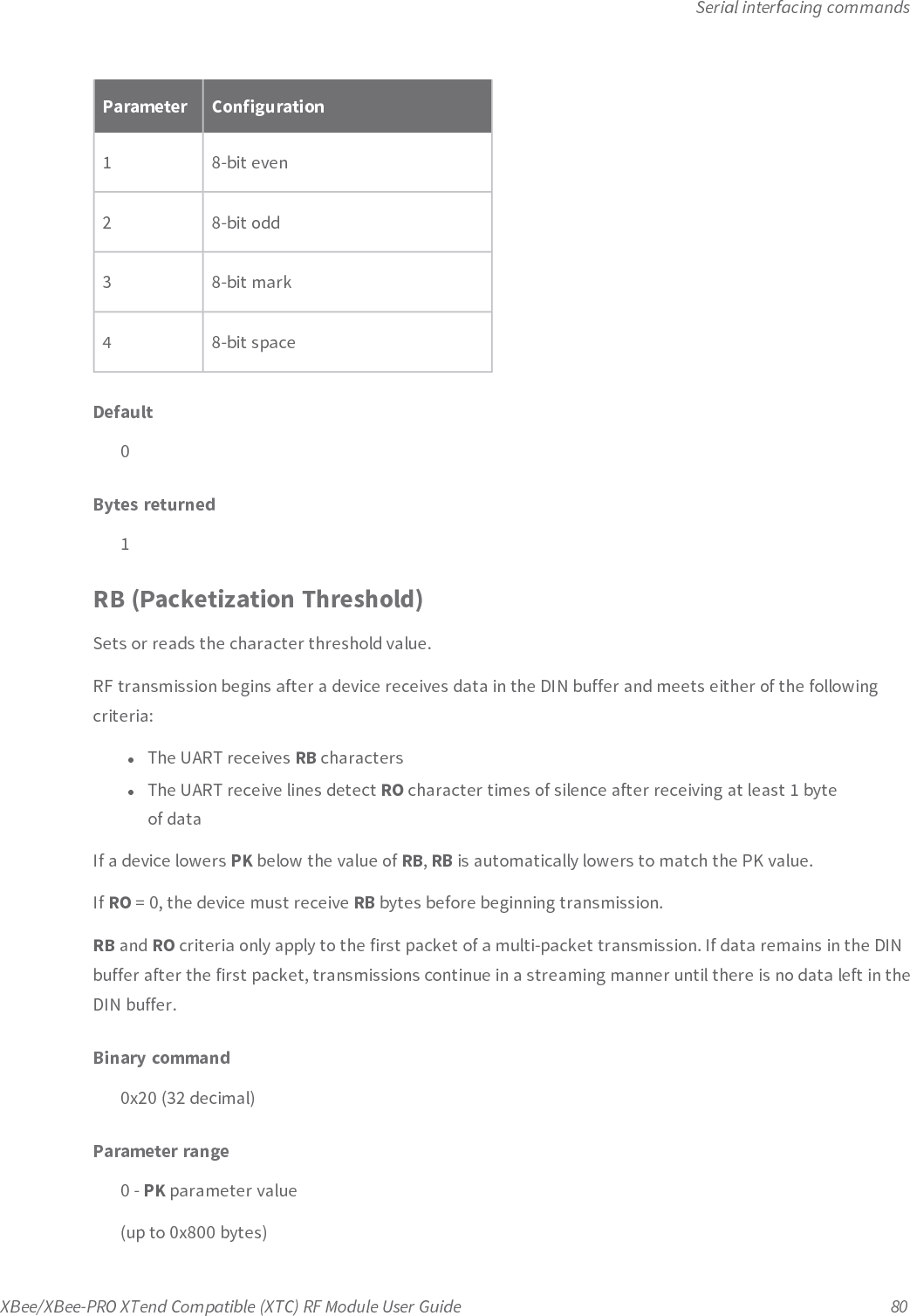
![Serial interfacing commandsXBee/XBee-PRO XTend Compatible (XTC) RF Module User Guide 79Bytes returned1FT (Flow Control Threshold)Sets or reads the flow control threshold.De-assert CTS when the number of bytes specified by the FT parameter are in the DIN buffer. Re-assertCTS when less than FT - 16 bytes are in the UART receive buffer.Binary command0x24 (36 decimal)Parameter range0x11 - 0xC00 [bytes]Default0xBBF (DI buffer size minus 0x11)Bytes returned2NB (Parity)Set or read the parity settings for UART communications.Binary command0x23 (35 decimal)Command typeSerial interfacingParameter range0 - 4Parameter Configuration0 8-bit (no parity or 7-bit (any parity)](https://usermanual.wiki/Digi/XBSX/User-Guide-2864252-Page-79.png)
![Serial interfacing commandsXBee/XBee-PRO XTend Compatible (XTC) RF Module User Guide 81Default0x800 (2048 bytes)Bytes returned2RO (Packetization Timeout)Set or read the number of character times of inter-character silence required before transmission begins.For information on how ROworks with the RB command, see RB (Packetization Threshold) on theprevious page.When RO is the transmission-beginning criteria:The actual time between the reception of the last character from the UART and the beginning of RFtransmission is at least 800 µsec longer than the actual RO time to allow for transmission setup. It is alsosubject to 100-200 µsec of additional uncertainty, which could be significant for small values of RO at highUART bit rates.The firmware calculates the correct UART character time (10, 11, or 12 bits) based on the followingcriteria:l1 start bitl8 data bitsl0 or 1 parity bit (as determined by the NB command)l1 or 2 stop bits (as determined by SB command)Binary command0x21 (33 decimal)Parameter range0 - 0x53E2 [x UART character times]Default3Bytes returned2](https://usermanual.wiki/Digi/XBSX/User-Guide-2864252-Page-81.png)
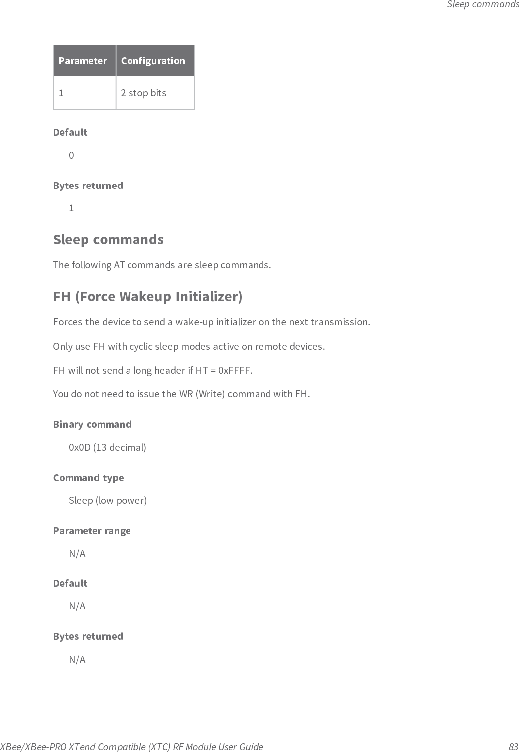
![Sleep commandsXBee/XBee-PRO XTend Compatible (XTC) RF Module User Guide 84HT (Time before Wake-up Initializer)Sets or reads the time of inactivity (no serial or RF data is sent or received) before a transmitting (TX)RFdevice sends a wake-up initializer. The main purpose of this command is to prevent devices from sendingthe Long Header with every data packet. For more information on long headers, see LH (Wakeup InitializerTimer) below.For RX devices operating in Cyclic Sleep mode (SM = 4-8), set HT to be shorter than the ST command.The TX device sends a wake-up initializer, which instructs all receiving (RX) devices to remain awake toreceive RF data.From the perspective of the RX device: after HT time elapses and the inactivity timeout (ST command) ismet, the RX device goes into cyclic sleep. In cyclic sleep, the RX device wakes once per sleep interval (SMcommand) to check for a wake-up initializer. When it detects a wake-up initializer, the device stays awaketo receive data. The wake-up initializer must be longer than the cyclic sleep interval to ensure thatsleeping devices detect incoming data.When HT time elapses, the TX device knows it needs to send a wake-up initializer for all RX devices toremain awake and receive the next transmission.Binary command0x03 (3 decimal)Command typeSleepParameter range0 - 0x53E2, 0xFFFF [x 100 ms]Default0xFFFF (wake-up initializer will not be sent)Bytes returned2LH (Wakeup Initializer Timer)Sets or reads the duration of time during which the wake-up initializer is sent. When receiving devices arein Cyclic Sleep Mode, they power-down after a period of inactivity as specified by the ST parameter and will](https://usermanual.wiki/Digi/XBSX/User-Guide-2864252-Page-84.png)
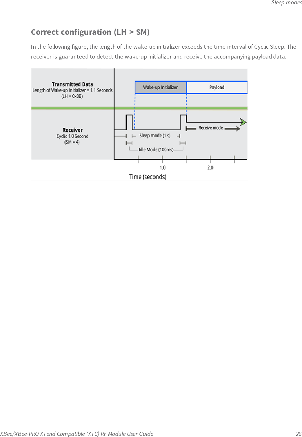
![Sleep commandsXBee/XBee-PRO XTend Compatible (XTC) RF Module User Guide 85periodically wake and listen for data transmissions. In order for the receiving devices to remain awake,they must detect ~35 ms of the wake-up initializer.You must use LH whenever a receiving device is operating in Cyclic Sleep mode. The wake-up initializertime must be longer than the cyclic sleep time, which is set by the SM (Sleep Mode) parameter. If thewake-up initializer time is less than the Cyclic Sleep interval, the connection is at risk of missing the wake-up initializer transmission.To view a diagram of the correct configuration, see Cyclic Sleep Mode (SM = 4-8) on page 27.Binary command0x0C (12 decimal)Command typeSleepParameter range0 - 0xFF [x100 milliseconds]Default1Bytes returned1PW (Pin Wakeup)Enables or disables the sleep pin.Under normal operation, a device in Cyclic Sleep mode cycles from an active state to a low-power state atregular intervals until it is ready to receive data. If you set PW to 1, you can use the SLEEP pin (pin 26) towake the device from Cyclic Sleep. When you de-assert (low) the SLEEP pin, the device is operational andwill not go into Cyclic Sleep.Once you assert the SLEEP pin, the device remains active for the period of time specified by the STparameter and returns to Cyclic Sleep mode if no data is ready to transmit. PW is only valid if Cyclic Sleepis enabled.Binary command0x1D (29 decimal)](https://usermanual.wiki/Digi/XBSX/User-Guide-2864252-Page-85.png)
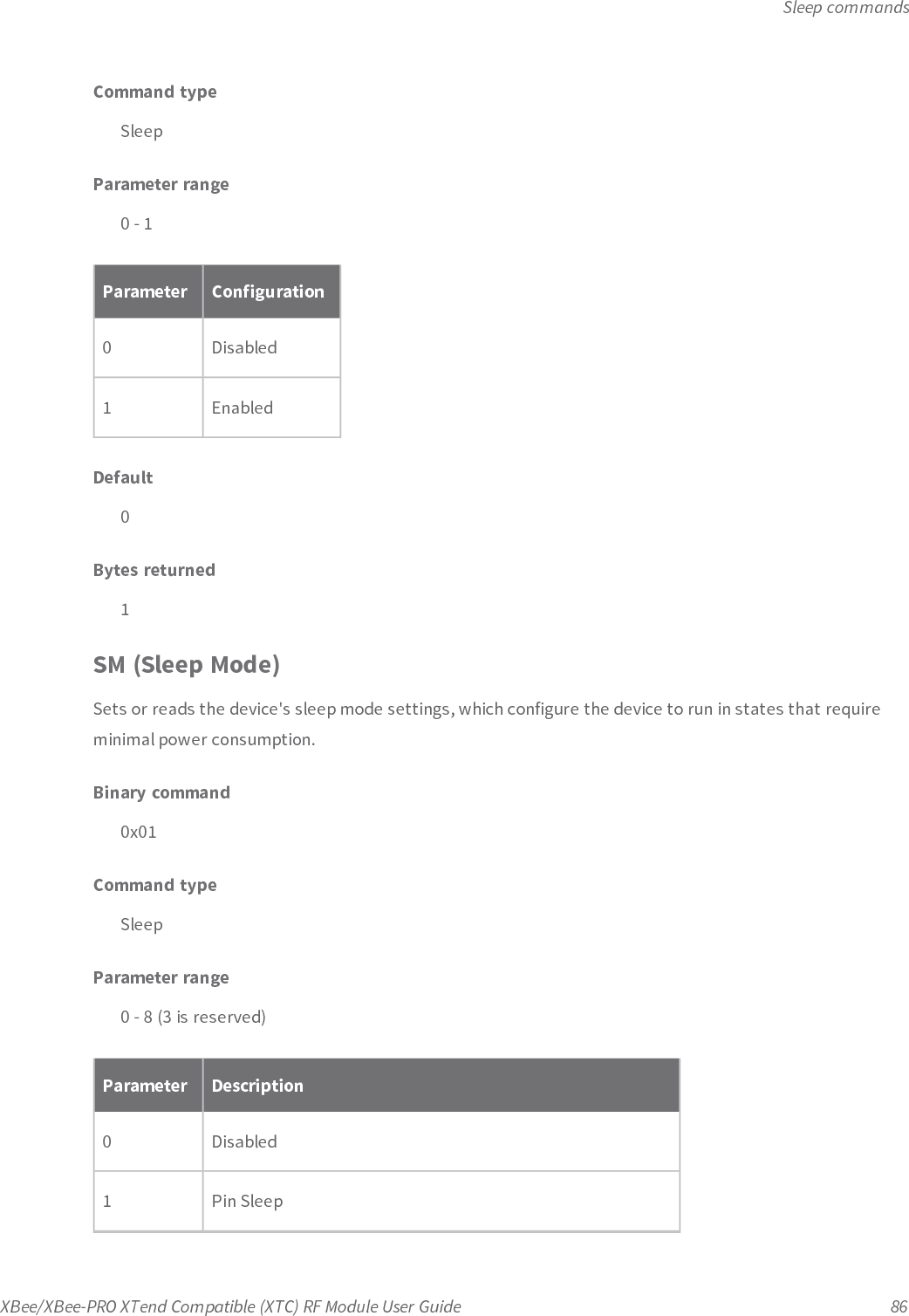
![Sleep commandsXBee/XBee-PRO XTend Compatible (XTC) RF Module User Guide 87Parameter Description2 Serial Port Sleep3 [reserved]4 Cyclic 1 second sleep (RF module wakes every 1.0 seconds)5 Cyclic 2 second sleep6 Cyclic 4 second sleep7 Cyclic 8 second sleep8 Cyclic 16 second sleepDefault0Bytes returned1ST (Time before Sleep)Sets or reads the amount of time (in milliseconds) that the device remains inactive before entering Sleepmode. For example, if you set STto 0x64 (100 decimal), the device enters Sleep mode after 10 seconds ofinactivity (no transmitting or receiving).You can only use this command if you use SM to select Cyclic Sleep or Serial Port Sleep mode settings; seeSM (Sleep Mode) on the previous page.Binary command0x02 (2 decimal)Command typeSleepParameter range(AT + 3) - 0x53E2 [x 100 ms]](https://usermanual.wiki/Digi/XBSX/User-Guide-2864252-Page-87.png)

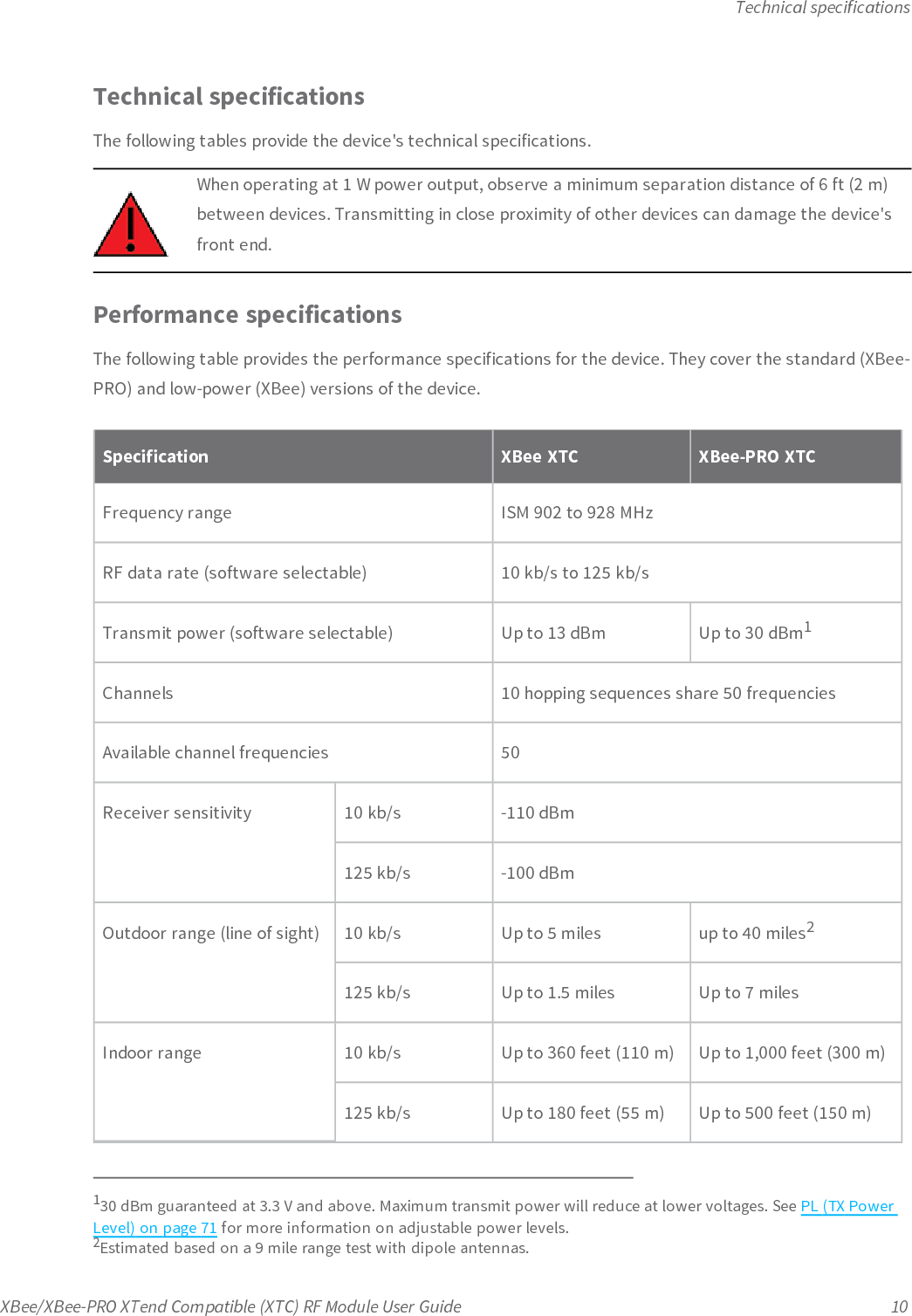
![Basic communicationsXBee/XBee-PRO XTend Compatible (XTC) RF Module User Guide 1093. Configure PK, RO and RB to ensure that the RF packet aligns with the protocol packet. Forexample:PK=0x100RB=0x100RO depends on baud rate4. Set MD = 5 to configure one or more devices that you do not intend to be repeaters asrepeater End Nodes in the system.5. Set MD = 6 to configure remote nodes as destinations. This ensures that the remote nodewaits for the repeater traffic to subside before it transmits a response.To configure a Repeater network for Basic addressed communications, use DT to assign uniqueaddresses to each device in the network.AT commands to configure Repeater network functionsThe following table lists the AT commands you use to configure repeater functions.ATCommandBinaryCommandAT CommandNameRange # BytesReturnedFactoryDefaultAM 0x3A (58d) Auto-set MY - - -DT 0x00 (0d) DestinationAddress0 - 0xFFFF 2 0MD 0x3C (60d) RF Mode 0 - 6 1 0MY 0x2A (42d) Source Address 0 - 0xFFFF 2 0xFFFFRN 0x19 (25d) Delay Slots 0 - 0xFF[slots]1 0WR 0x08 (8d) Write - - -Repeater network algorithm detailsThe firmware uses an algorithm to propagate each RF packet through the entire repeater network. Withina repeater network, the firmware only defines Repeater Nodes and repeater End Nodes. Repeater Nodesforward messages on to other devices within range; End Nodes do not.](https://usermanual.wiki/Digi/XBSX/User-Guide-2864252-Page-109.png)