User Manual

XBee/XBee-PRO XTC
Radio Frequency (RF) Module
User Guide

Revision history
900001476 A
Revision Date Description
A December, 2015 Baseline release of the document.
Trademarks and copyright
Digi, Digi International, and the Digi logo are trademarks or registered trademarks in the United States
and other countries worldwide. All other trademarks mentioned in this document are the property of their
respective owners.
© 2015 Digi International Inc. All rights reserved.
Disclaimers
Information in this document is subject to change without notice and does not represent a commitment
on the part of Digi International. Digi provides this document “as is,” without warranty of any kind,
expressed or implied, including, but not limited to, the implied warranties of fitness or merchantability for
a particular purpose. Digi may make improvements and/or changes in this manual or in the product(s)
and/or the program(s) described in this manual at any time.
Warranty
To view the product's warranty information, go to the following website:
http://www.digi.com/howtobuy/terms
Customer support
Telephone (8:00 am — 5:00 pm U.S. Central Time):
Toll-free US and Canada: 866.912.3444
Worldwide: +1 952.912.3456
Online: www.digi.com/support/eservice
Mail:
Digi International Inc.
11001 Bren Road East
Minnetonka, MN 55434
USA
XBee/XBee-PRO XTend Compatible (XTC) RF Module User Guide 2

XBee/XBee-PRO XTend Compatible (XTC) RF Module User Guide 3
Contents
Revision history 2
The XBee/XBee-PRO XTend Compatible (XTC) RF module
About the XTCRF module 9
Applicable firmware 9
Technical specifications 10
Performance specifications 10
Power requirements 11
Networking and security specifications 11
Physical specifications 12
Regulatory approvals 12
Hardware
Mechanical drawings 14
Pin signals 16
Recommended pin connections 18
XTC RF Module Modes
Transparent and API operating modes 19
Transparent operating mode 19
API operating mode 19
Additional modes 20
Command mode 20
Binary Command mode 20
Idle mode 20
Receive mode 20

XBee/XBee-PRO XTend Compatible (XTC) RF Module User Guide 4
Sleep modes 21
Shutdown mode 21
Transmit mode 21
Enter Command mode 21
Send AT commands 22
Exit Command mode 22
Enter Binary Command mode 23
Exit Binary Command mode 23
Binary Command mode FAQs 23
Sleep modes 25
Pin Sleep (SM = 1) 26
Serial Port Sleep (SM = 2) 27
Cyclic Sleep Mode (SM = 4-8) 27
Operation
Serial interface 29
UART data flow 29
Serial data 29
Flow control 30
Data In (DIN) buffer and flow control 30
Data Out (DO) buffer and flow control 31
Configure the XTC RF Module
Configure the device using XCTU 33
Program the XTC RF Module
XTC RF Module programming examples 34
Connect the device to a PC 34
Modify a device address 35
Restore device defaults 35
Send binary commands 35
Query binary commands 36
XTC RF Module commands
Command mode options 41
AT (Guard Time After) 41
BT (Guard Time Before) 41

XBee/XBee-PRO XTend Compatible (XTC) RF Module User Guide 5
CC (Command Sequence Character) 42
CF (Number Base) 42
CN (Exit Command Mode) 43
CT (Command Mode Timeout) 44
E0 (Echo Off) 44
E1 (Echo On) 45
Diagnostic commands 45
%V (Board Voltage) 45
DB (Received Signal Strength) 46
GD (Receive Good Count) 47
HV (Hardware Version) 48
RC (Ambient Power - Single Channel) 48
RE (Restore Defaults) 49
RM (Ambient Power) 50
RP (RSSI PWM Timer) 51
SH (Serial Number High) 52
SL (Serial Number Low) 52
TP (Board Temperature) 53
TR (Transmit Error Count) 53
VL (Firmware Version - Verbose) 54
VR (Firmware Version - Short) 54
WA (Active Warning Numbers) 55
WN (Warning Data) 56
WS (Sticky Warning Numbers) 58
MAC/PHY commands 58
AM (Auto-set MY) 58
DT (Destination Address) 59
HP (Preamble ID) 60
ID (Network ID) 60
MK (Address Mask) 61
MT (Multi-transmit) 61
MY (Source Address) 62
RN (Delay Slots) 63
RR (Retries) 64
TT (Streaming Limit) 64
RF interfacing commands 65
BR (RF Data Rate) 65
FS (Forced Synch Time) 66
MD (RF Mode) 66
PB (Polling Begin Address) 67

XBee/XBee-PRO XTend Compatible (XTC) RF Module User Guide 6
PD (Minimum Polling Delay) 68
PE (Polling End Address) 68
PK (Maximum RF Packet Size) 69
PL (TX Power Level) 71
TX (Transmit Only) 72
Security commands 73
KY (AES Encryption Key) 73
Serial interfacing commands 73
AP (API Enable) 74
BD (Interface Data Rate) 74
CD (GP02 Configuration) 76
CS (GP01 Configuration) 77
FL (Software Flow Control) 78
FT (Flow Control Threshold) 79
NB (Parity) 79
RB (Packetization Threshold) 80
RO (Packetization Timeout) 81
RT (GPI1 Configuration) 82
SB (Stop Bits) 82
Sleep commands 83
FH (Force Wakeup Initializer) 83
HT (Time before Wake-up Initializer) 84
LH (Wakeup Initializer Timer) 84
PW (Pin Wakeup) 85
SM (Sleep Mode) 86
ST (Time before Sleep) 87
XTC RF ModuleSpecial commands 88
WR (Write) 88
XTC RF Module API operation
API mode overview 89
API frame specifications 89
Calculate and verify checksums 91
Escaped characters in API frames 92
XTC RF ModuleAPI frame overview 93
RF Module Status 0x8A 93
Transmit Request: 16-bit address 0x01 94
Transmit Status frame 0x89 96
Receive Packet: 16-bit address 0x81 97

XBee/XBee-PRO XTend Compatible (XTC) RF Module User Guide 7
Network configurations
network topologies 100
Point-to-point networks 100
Point-to-multipoint networks 101
Peer to peer networks 102
Addressing 103
Address recognition 103
Basic communications 104
Streaming mode (default) 104
Multi-transmit mode 105
Repeater mode 106
Polling mode (basic) 111
Acknowledged communications: Acknowledged mode 113
Acknowledged mode connection sequence 114
Polling mode (acknowledged) 115
Certifications
FCC (United States) 117
OEM labeling requirements 117
FCC notices 118
FCC antenna certifications 118
XBee-PRO XTC Antenna options 119
XBee XTC antenna options 127
Industry Canada (IC) 135
Labeling requirements 135
Transmitters for detachable antennas 136
Detachable antennas 136
ACMA (Australia) 137
Power requirements 137
PCB design and manufacturing
Recommended footprint and keepout 138
Design notes 140
Host board design 140
Improve antenna performance 141
RF pad version 141
Recommended solder reflow cycle 143
Flux and cleaning 144


XBee/XBee-PRO XTend Compatible (XTC) RF Module User Guide 9
The XBee/XBee-PRO XTend Compatible (XTC) RF
module
About the XTCRF module
The XBee/XBee-PRO XTend Compatible (XTC) RF module provides a radio frequency (RF) solution for the
reliable delivery of critical data between remote devices. It is a 30 dBm (1 Watt) long-range original
equipment manufacturer (OEM) device. We also offer a low power version of this module that offers
transmit power adjustable up to 13 dBm.
The XTC module uses Frequency Hopping Spread Spectrum (FHSS) agility to avoid interference by hopping
to a new frequency on every packet transmission or re-transmission. Its transmit power is software
adjustable up to 30 dBm, which is the maximum output power allowable by governments that use 900
MHz as a license-free band. The XTC module is approved for use in the United States, Canada, Australia
and other countries.
The XTC transfers a standard asynchronous serial data stream, operates within the ISM 900 MHz
frequency band and offers two RF data rates of 10 kb/s and 125 kb/s.
As the name suggests, the XTC is over-the-air compatible with Digi's XTend module. The XTC is not a drop-
in replacement for the XTend. If you require form factor compatibility, you must use the XTend vB RF
Module.
For new applications, we recommend that you use the XBee/XBee-Pro SX module. It uses the same
hardware as the XTC but we optimize the firmware for the best range and interference immunity.
However, it is not over-the-air compatible with the XTend.
Applicable firmware
This manual supports the following firmware:
l0x200X for XTC Hopping

Technical specifications
XBee/XBee-PRO XTend Compatible (XTC) RF Module User Guide 10
Technical specifications
The following tables provide the device's technical specifications.
When operating at 1 W power output, observe a minimum separation distance of 6 ft (2 m)
between devices. Transmitting in close proximity of other devices can damage the device's
front end.
Performance specifications
The following table provides the performance specifications for the device. They cover the standard (XBee-
PRO) and low-power (XBee) versions of the device.
Specification XBee XTC XBee-PRO XTC
Frequency range ISM 902 to 928 MHz
RF data rate (software selectable) 10 kb/s to 125 kb/s
Transmit power (software selectable) Up to 13 dBm Up to 30 dBm1
Channels 10 hopping sequences share 50 frequencies
Available channel frequencies 50
Receiver sensitivity 10 kb/s -110 dBm
125 kb/s -100 dBm
Outdoor range (line of sight) 10 kb/s Up to 5 miles up to 40 miles2
125 kb/s Up to 1.5 miles Up to 7 miles
Indoor range 10 kb/s Up to 360 feet (110 m) Up to 1,000 feet (300 m)
125 kb/s Up to 180 feet (55 m) Up to 500 feet (150 m)
130 dBm guaranteed at 3.3 V and above. Maximum transmit power will reduce at lower voltages. See PL (TX Power
Level) on page 71 for more information on adjustable power levels.
2Estimated based on a 9 mile range test with dipole antennas.

Technical specifications
XBee/XBee-PRO XTend Compatible (XTC) RF Module User Guide 11
Power requirements
The following table provides the power requirements for the device.
Specification XBee XTC XBee-PRO XTC
Supply voltage 2.4 to 3.6 VDC, 3.3 V typical 2.6 to 3.6 VDC, 3.3 V typical
Receive current VCC = 3.3 V 40 mA 40 mA
Transmit current VCC = 3.3 V 55 mA @ 13 dBm 900 mA @ 30 dBm
VCC = 3.3 V 45 mA @ 10 dBm 640 mA @ 27 dBm
VCC = 3.3 V 35 mA @ 0 dBm 330 mA @ 20 dBm1
Sleep current 2.5 µA 2.5 µA
Networking and security specifications
The following table provides the networking and security requirements for the device.
Specification Value
Frequency 902-928 MHz, 915-928 MHz for the International variant
Spread spectrum Frequency Hopping Spread Spectrum (FHSS)
Modulation Frequency Shift Keying (FSK/GFSK)
Supported network
topologies
Peer-to-peer (master/slave relationship not required), point-to-point, and
point-to-multipoint
Channel capacity 10 hop sequences share 50 frequencies
1We do not recommend the 20 dBm power level when operating at temperatures below 0°C. Output power may
vary significantly when operating below 0°C.

Technical specifications
XBee/XBee-PRO XTend Compatible (XTC) RF Module User Guide 12
Specification Value
Encryption 256-bit or 128-bit AES depending on region, not software selectable
256-bit is only available on the North American variant
128-bit is only available on the Australian and international variants
The KY command enables and disables encryption. The KY command sets
the key
Physical specifications
The following table provides the physical specifications for the device.
Specification Value
Dimensions 1.33 x 0.87 x 0.12" (3.38 x 2.21 x 1.29 cm)
Weight 3 g
RoHS Compliant
Manufacturing ISO 9001:2000 registered standards
Connector 37 castellated SMT pads
Antenna connector options U.FL or RF pad
Antenna impedance 50 ohms unbalanced
Maximum input RF level at antenna port 6 dBm
Operating temperature -40°C to 85°C
Regulatory approvals
The following table provides the regulatory approvals for the device.

Technical specifications
XBee/XBee-PRO XTend Compatible (XTC) RF Module User Guide 13
Country XBee XTC XBee-PROXTC
United States FCC ID: MCQ-XBSX (pending) FCC ID: MCQ-XBPSX (pending)
Canada IC: 1846A-XBSX (pending) IC: 1846A-XBPSX (pending)
Australia RCM (pending) RCM (pending)

XBee/XBee-PRO XTend Compatible (XTC) RF Module User Guide 14
Hardware
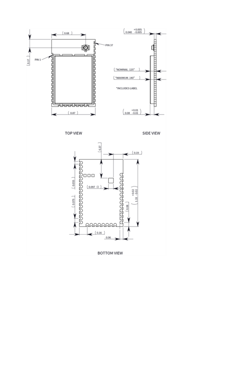
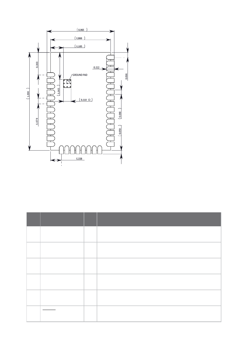
Mechanical drawings
The following images show the XTC mechanical drawings. The XTC has the same form factor as other Digi
surface mount (SMT) XBee devices, except there is an additional copper ground pad on the bottom.
Mechanical drawings
XBee/XBee-PRO XTend Compatible (XTC) RF Module User Guide 15
Pin signals
XBee/XBee-PRO XTend Compatible (XTC) RF Module User Guide 16
Pin signals
The following table describes the pin signals. Low-asserted signals have a horizontal line over the signal
name.
Pin Designation I/O Function
1 GND - Ground
2 VCC I Power supply
3 DOUT O UART Data Out
4 DIN I UART Data In
5 GPO2/RX LED O General Purpose Output / RX LED
6RESET I Module reset

Pin signals
XBee/XBee-PRO XTend Compatible (XTC) RF Module User Guide 17
Pin Designation I/O Function
7 RSSI O RX Signal Strength Indicator
8 - Disabled
9 Reserved NC Do not connect
10 SLEEP (DTR) I Pin Sleep Control Line
11 GND - Ground
12 - Disabled
13 GND - Ground
14 - Disabled
15 - Disabled
16 - Disabled
17 - Disabled
18 Reserved NC Do not connect
19 Reserved NC Do not connect
20 Reserved NC Do not connect
21 Reserved NC Do not connect
22 GND - Ground
23 Reserved NC Do not connect
24 - Disabled

Pin signals
XBee/XBee-PRO XTend Compatible (XTC) RF Module User Guide 18
Pin Designation I/O Function
25 GPO1/CTS/RS-
485 TX_EN
O General Purpose Output / Clear-to-Send Flow Control /
RS-485 Transmit Enable
26 ON/SLEEP O Module sleep status indicator
27 Reserved NC Do not connect
28 TX_PWR O Transmit power
29 RTS/CMD I Request-to-Send Flow Control / Binary Command Control
30 - Disabled
31 - Disabled
32 CONFIG I Configuration
33 - Disabled
34 Reserved NC
35 GND - Ground
36 RF I/O RF IO for RF pad variant
37 NC NC
38 GND - Ground pad for heat transfer to host PCB
Note If you integrate the XTC with a host PC board, leave all lines you do not use disconnected
(floating).
Recommended pin connections
The only required pin connections are VCC, GND, DOUT and DIN. To support serial firmware updates, you
should connect VCC, GND, DOUT, DIN, RTS, and SLEEP (DTR).

XBee/XBee-PRO XTend Compatible (XTC) RF Module User Guide 19
XTC RF Module Modes
Transparent and API operating modes
The firmware operates in several different modes. Two top-level modes establish how the device
communicates with other devices through its serial interface: Transparent operating mode and API
operating mode.
Transparent operating mode
Devices operate in this mode by default. We also call this mode “AT operating mode.” The device acts as a
serial line replacement when it is in Transparent operating mode. The device queues all UART data it
receives through the DIN pin for RF transmission. When a device receives RF data, it sends the data out
through the DOUT pin. You can set the configuration parameters using the AT Command interface.
API operating mode
API operating mode is an alternative to Transparent mode. API mode is a frame-based protocol that
allows you to direct data on a packet basis. It can be particularly useful in large networks where you need
to control the route a data packet takes or when you need to know which node a data packet is from. The
device communicates UART data in packets, also known as API frames. This mode allows for structured
communications with serial devices. It is helpful in managing larger networks and is more appropriate for
performing tasks such as collecting data from multiple locations or controlling multiple devices remotely.
There are two types of API operating modes: one with escaped characters and another without escaped
characters.
lWithout escaped characters (AP = 1). This mode eliminates escaping character sequences.
This makes it simpler to create code and libraries, but runs a minor risk of lost frames or
errors due to the possibility that payload data can be confused with frame structure. We
do not recommend this mode for noisy radio environments and where payload data may
include special characters (specifically 0x7E, 0x7D, 0x11, and 0x13).

Additional modes
XBee/XBee-PRO XTend Compatible (XTC) RF Module User Guide 20
lWith escaped characters (AP = 2). API escaped operating mode works similarly to API
mode. The only difference is that when working in API escaped mode, the software must
escape any payload bytes that match API frame specific data, such as the start-of-frame
byte (0x7E).
Additional modes
In addition to the serial communication modes, several modes apply to how to configure devices and how
devices communicate with each other.
Command mode
Command mode is a state in which the firmware interprets incoming characters as commands. Command
mode allows you to modify the device’s firmware using parameters you can set using AT commands. When
you want to read or set any setting of the device, you have to send it an AT command. Every AT command
starts with the letters "AT" followed by the two characters that identify the command the device issues
and then by some optional configuration values. For more details, see Enter Command mode on the next
page.
Binary Command mode
Binary Command mode allows you to configure a device at a faster rate than AT commands will allow.
Using binary commands to send and receive parameter values is the fastest way to change the operating
parameters of the device. Use binary commands to:
lSample signal strength and/or error counts;
lChange device addresses and channels for polling systems when a quick response is
necessary.
For more details, see Enter Binary Command mode on page 23 and DB (Received Signal Strength) on page
46.
Idle mode
When not receiving or transmitting data, the device is in Idle mode. During Idle mode, the device listens for
valid data on the serial port.
Receive mode
If a destination node receives a valid RF packet, the destination node transfers the data to its serial
transmit buffer. For the serial interface to report receive data on the RF network, that data must meet
the following criteria:

Additional modes
XBee/XBee-PRO XTend Compatible (XTC) RF Module User Guide 21
lID match
lChannel match
lAddress match
Sleep modes
Sleep Modes enable the device to enter states of low-power consumption when not in use. The device
support three software sleep modes:
lPin Sleep: the host controls this
lSerial Port Sleep: wakes when it detects serial port activity
lCyclic Sleep: wakes when it detects RF activity
For more information, see Sleep modes on page 25.
Shutdown mode
Shutdown mode offers the lowest power mode available to the device. This is helpful for applications that
must keep power consumption to a minimum during idle periods.
When you drive the SHDN pin (pin 7) low, it forces the device into Shutdown mode. This halts any
communication in progress (transmit or receive) and any buffered data is lost. For any other mode of
operation, you must drive or pull SHDN high.
Immediately after the SHDN pin changes states from low to high, the device resets. After reset, the
application must observe a delay time of <100 ms.
While SHDN is driven low, the device sets the following pins to high impedance: DCD, TX_PWR, RX LED, DO
and CTS. The SHDN line is driven low during shutdown.
The following input pins may continue to be driven by external circuitry when in shutdown mode: RTS, DI
and SHDN.
Because the DO pin is set to high impedance during Shutdown, if the XTC RF Module is connected to a
processor, the UART receive pin could be floating. Place a weak pull-up between the device and the
microcontroller so that the application does not misinterpret noise as data.
Transmit mode
When the device receives serial data and is ready to packetize it, the device exits Idle mode and attempts
to transmit the serial data.
Enter Command mode
There are two ways to enter Command mode:
Additional modes
XBee/XBee-PRO XTend Compatible (XTC) RF Module User Guide 22
1. To get a device to switch into this mode, you must issue a unique string of text in a special
way: +++ (default). When the device sees a full second of silence in the data stream
followed by the string +++ (without Enter or Return) and another full second of silence, it
knows to stop sending data through and start accepting commands locally.
Do not press Return or Enter after typing +++ because it will interrupt the guard time
silence and prevent you from entering Command mode.
2. Assert (low) the CONFIG pin. Turn the power going to the device off and back on.
The device sends the letters OK followed by a carriage return out of the UART to indicate that it entered
Command mode.
You can customize the guard times and timeout in the device’s configuration settings. See CC (Command
Sequence Character) on page 42, BT (Guard Time Before) on page 41 and AT (Guard Time After) on page
41.
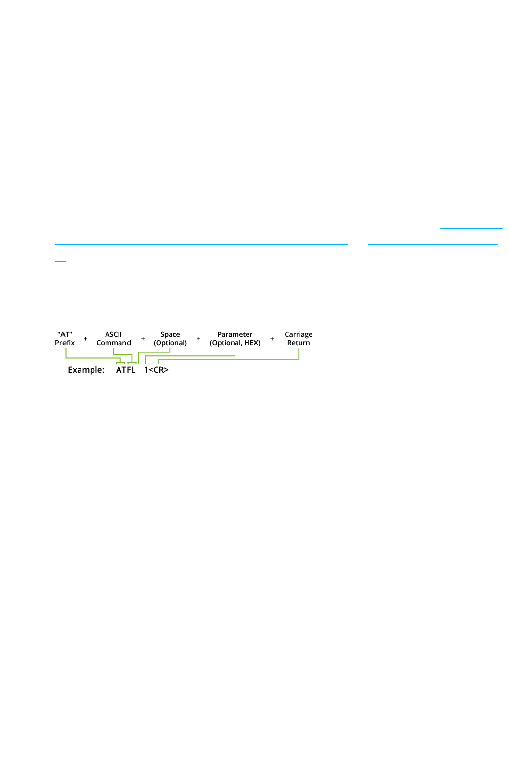
Send AT commands
Once the device enters Command mode, use the syntax in the following figure to send AT commands.
To read a parameter value stored in the device’s register, omit the parameter field.
The preceding example would enable software flow control.
To store the new value to non-volatile (long term) memory, send the WR (Write) command. This allows
parameter values that you modify to persist in the device's registry after a reset. Otherwise, the device
restores parameters to the previous values after a reset.
Respond to AT commands
When you send a command to the device, the device parses and runs the command. If the command runs
successfully, the device returns an OK message. If the command errors, the device returns an ERROR
message.
Exit Command mode
1. Send the CN (Exit Command Mode) command followed by a carriage return.
or:
2. If the device does not receive any valid AT commands within the time specified by CT
(Command Mode Timeout), it returns to Idle mode. The default Command Mode Timeout is
20 seconds.

Additional modes
XBee/XBee-PRO XTend Compatible (XTC) RF Module User Guide 23
Enter Binary Command mode
To enter Binary Command mode, you must first be in Command mode:
1. Set RT to 1; see RT (GPI1 Configuration) on page 82.
2. Assert CMD by driving pin 1029 high to enter Binary Command mode.
3. Disable hardware flow control.
CTS (pin 25) is high when the firmware executes a command. That is why you must disable hardware flow
control, because CTS holds off parameter bytes.
Exit Binary Command mode
To exit Binary Command mode, de-assert CMD by driving pin 2910 low.
Binary Command mode FAQs
Since sending and receiving binary commands takes place through the same serial data path as live data,
interference between the two types of data can be a concern. Some common questions about using binary
commands are:
lWhat are the implications of asserting CMD while the device is sending or receiving live
data?
You must assert the CMD pin (pin 2910) in order to send binary commands to the device. You can assert
the CMD pin to recognize binary commands anytime during the transmission or reception of data.
The device only checks the status of the CMD signal at the end of the stop bit as the byte shifts into the
serial port.
The firmware does not allow control over when the device receives data, except by waiting for dead
time between bursts of communication.
If the command is sent in the middle of a stream of payload data, the device executes the command in
the order it is received. If the device is continuously receiving data, it waits for a break in the data it
receives before executing the command.
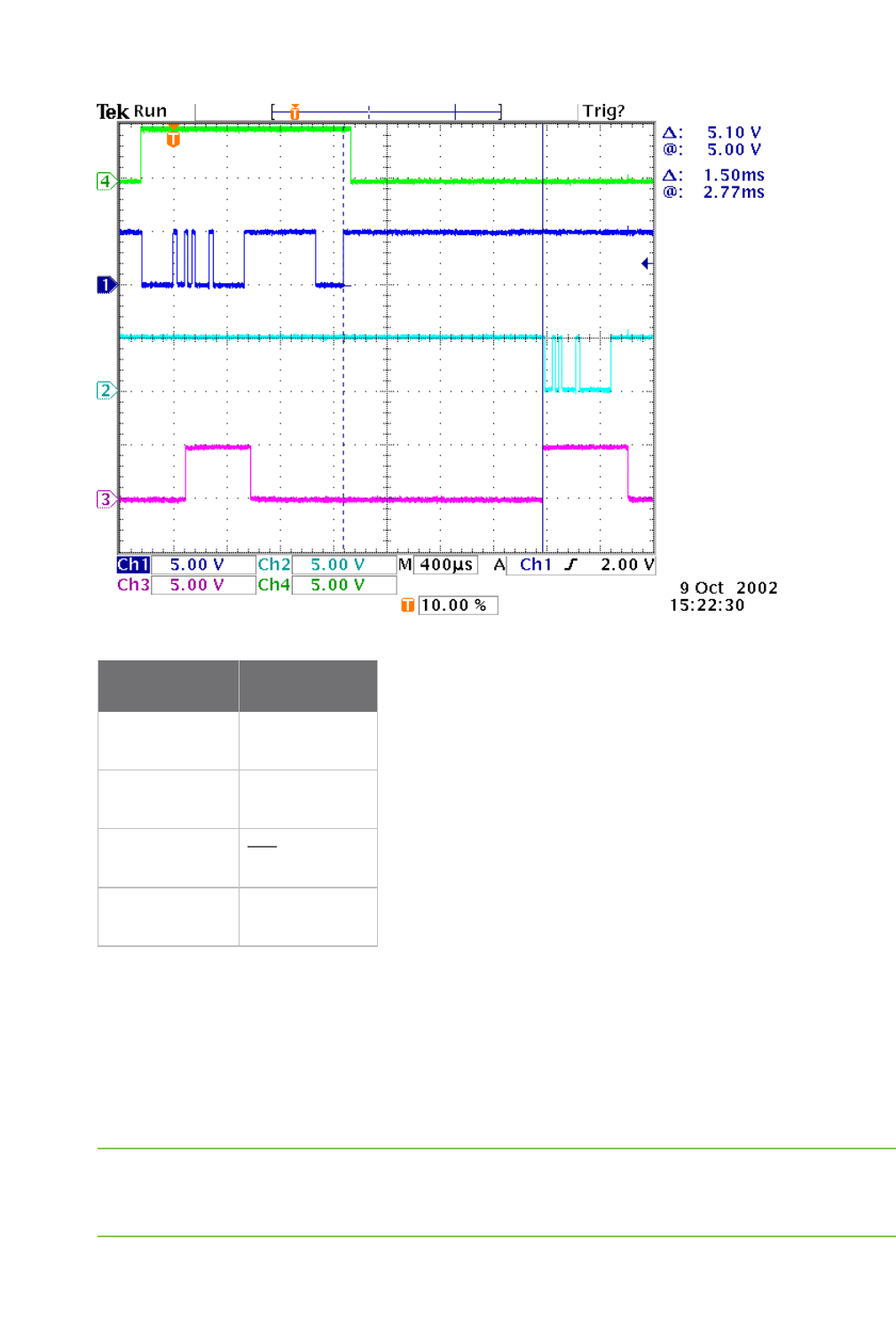
In the following figure, the host writes a value to a register and then reads it out of the device to verify
it. While not in the middle of other received data, the CTS signal outlines the data response out of the
device.
Additional modes
XBee/XBee-PRO XTend Compatible (XTC) RF Module User Guide 24
Signal number Pin name
1 DIN (Pin 4)
2 DOUT (Pin 3)
3 CTS (Pin 259)
4 CMD (Pin 2910)
lAfter sending serial data, is there a minimum time delay before you can assert CMD?
lIs a time delay required after CMD is de-asserted before payload data can be sent?
The host must observe a minimum time delay of 100 µs after sending the stop bit of the command byte
before the host de-asserts the CMD pin. The command executes after the host sends all of its
associated parameters. If the device does not receive all of these parameters within 0.5 seconds, the
device returns to Idle mode.
Note When a host sends parameters, they are two bytes long with the least significant byte sent first.
Binary commands that return one parameter byte must be written with two parameter bytes.
Example: to set PL to 3, send the following data: 0x3A 0x03 0x00 (Binary Command, LSB, MSB).

Sleep modes
XBee/XBee-PRO XTend Compatible (XTC) RF Module User Guide 25
lHow does one discern between live data and data received in response to a command?
To query command parameters using Binary Command mode, set the most significant bit of the binary
command. This can be accomplished by logically ORing (bit-wise) the binary command with
hexadecimal 0x80. The parameter bytes are returned in hexadecimal bytes with the least significant
bit first (if multiple bytes are returned).
Example: to query HP in Binary Command mode, instead of setting it, send 0x11 (HP binary command)
as 0x91 with no parameter bytes.
The device must be in Binary Command mode in order for the device to recognize a binary command;
see Enter Binary Command mode on page 23.
If the device is not in Binary Command mode (the RT parameter value is not 1), the device does not
recognize that the CMD pin is asserted and therefore does not recognize the data as binary
commands.
For an example of binary programming, see Send binary commands on page 35.
Sleep modes
For the device to enter one of the sleep modes, SM must have a non-zero parameter value, and it must
meet one of the following conditions:
1. The device is idle (no data transmission or reception) for the amount of time defined by
the ST parameter. ST is only active when SM = 4-5.
2. The host asserts SLEEP (pin 10). This only applies to the Pin Sleep option.
When in Sleep mode, the device does not transmit or receive data until it transitions to Idle mode.
Use the SM command to enable or disable all Sleep modes. The following table shows the transitions into
and out of Sleep modes.
Sleep
mode
(setting)
Transition into
Sleep mode
Transition out of Sleep
mode (wake)
Related
commands
Power
consumption
Pin Sleep
(SM = 1)
Assert (high) SLEEP pin. A
microcontroller can shut
down and wake devices via
the SLEEP pin.
The device completes a
transmission or reception
before activating Pin Sleep.
De-assert (low) SLEEP pin SM < 147 µA

Sleep modes
XBee/XBee-PRO XTend Compatible (XTC) RF Module User Guide 26
Sleep
mode
(setting)
Transition into
Sleep mode
Transition out of Sleep
mode (wake)
Related
commands
Power
consumption
Serial
Port
Sleep
(SM = 2)
Automatic transition to Sleep
Mode occurs after a user-
defined period of inactivity
(no transmitting or receiving
of data).
Period of inactivity is defined
by the ST command.
When a serial byte is
received on the DI pin
(SM), ST 7.3 mA
Cyclic
Sleep
(SM = 4 -
8)
The device transitions in and out of Sleep Mode in cycles
(you set the sleep interval of time using the SM command).
The cyclic sleep interval of time must be shorter than the
interval of time that is defined by the LH command.
You can for the device into Idle Mode using the SLEEP pin if
you issue the PW command.
(SM), ST,
HT, LH, PW
See Power
requirements
The SM (Sleep Mode) command is central to setting all Sleep Mode configurations. By default, Sleep Modes
are disabled (SM = 0) and the device remains in Idle/Receive Mode. When in this state, the device remains
constantly ready to respond to serial or RF activity.
Pin Sleep (SM = 1)
lPin/Host-controlled
lTypical sleep current: 2.5 µA
When the host asserts the SLEEP pin, the device finishes any transmitting or receiving activity, enters Idle
mode, then enters a sleep state. When in Pin Sleep mode, the device does not respond to serial or RF
activity.
After enabling Pin Sleep, the SLEEP pin controls whether the device is active or sleeping. When the host de-
asserts SLEEP, the device is fully operational. When the host asserts SLEEP, the device transitions to Sleep
mode and remains in its lowest power-consuming state until the host de-asserts the pin. This pin is only
active if the device is setup to operate in this mode; otherwise the firmware ignores the pin.
Once in Pin Sleep, the device de-asserts (high) CTS (pin 259) , indicating that other devices should not send
data to the device. The device also de-asserts (low) the TX_PWR line (pin 284) when the device is in Pin
Sleep mode.
Note The device completes a transmission or reception before activating Pin Sleep.

Sleep modes
XBee/XBee-PRO XTend Compatible (XTC) RF Module User Guide 27
Serial Port Sleep (SM = 2)
lWake on serial port activity
lTypical sleep current: 6.3 mA
Serial Port Sleep is a Sleep mode in which the device runs in a low power state until it detects serial data
on the DI pin.
The ST command determines the period of time that the device sleeps. Once it receives a character
through the DI pin, the device returns to Idle mode and is fully operational.
Cyclic Sleep Mode (SM = 4-8)
lTypical sleep Current: 2.5 µA (when asleep)
Cyclic Sleep modes allow device wakes according to the times designated by the cyclic sleep settings. If
the device detects a wake-up initializer during the time it is awake, the device synchronizes with the
transmitting device and receives data after the wake-up initializer runs its duration. Otherwise, the device
returns to Sleep mode and continues to cycle in and out of activity until a wake-up initializer is detected.
While the device is in Cyclic Sleep mode, it de-asserts (high) CTS (pin 259) to indicate not to send data to
the device. When the device awakens to listen for data, it asserts CTS and transmits any data received on
the DI pin. The device also de-asserts (low) the TX_PWR (pin 284) when it is in Cyclic Sleep mode.
The device remains in Sleep mode for a user-defined period of time ranging from 1 second to 16 seconds
(SM parameters 4 through 8). After this interval of time, the device returns to Idle mode and listens for a
valid data packet. The listen time depends on the BR parameter setting. The default BR setting of 1
requires at least a 35 ms wake time, while the BR setting of 0 requires a wake time of up to 225 ms. If the
device does not detect valid data on any frequency, it returns to Sleep mode. If it detects valid data, it
transitions into Receive mode and receives the incoming RF packets. The device then returns to Sleep
mode after a period of inactivity determined by the ST parameter.
You can also configure the device to wake from cyclic sleep when the SLEEP pin is de-asserted. To
configure a device to operate in this manner, you must issue the PW (Pin Wake-up) command. When you
de-assert the SLEEP pin, it forces the device into Idle mode and it can begin transmitting or receiving data.
It remains active until it no longer detects data for the time that ST specifies, at which point it resumes its
low-power cyclic state.
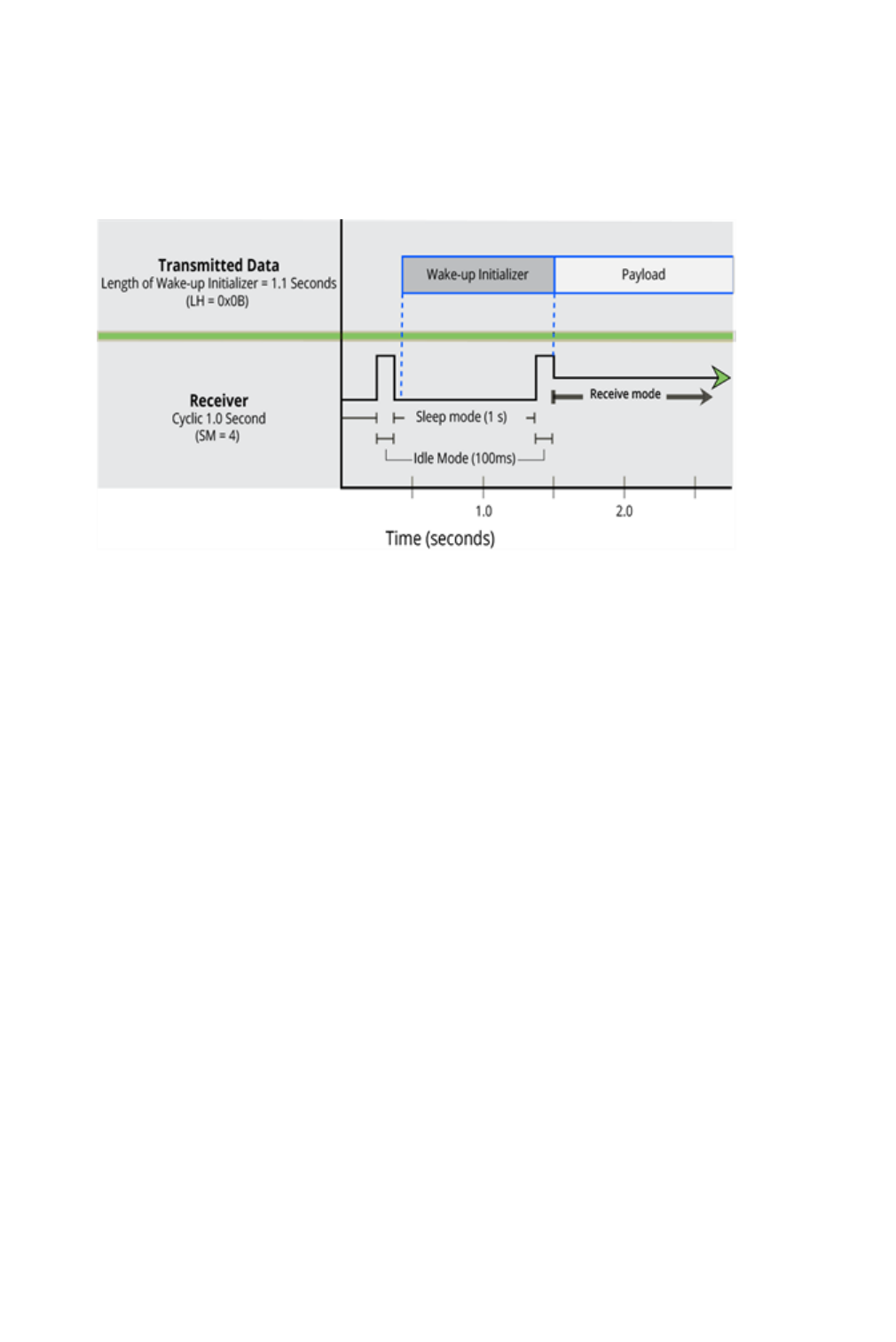
Cyclic scanning
Each RF transmission consists of an RF initializer and payload. The RF initializer contains initialization
information and all receiving devices must wake during the wake-up initializer portion of data
transmission in order to synchronize with the transmitting device and receive the data.
The cyclic interval time defined by the SM (Sleep Mode) command must be shorter than the interval time
defined by LH (Wake-up Initializer Timer) command.
Sleep modes
XBee/XBee-PRO XTend Compatible (XTC) RF Module User Guide 28
Correct configuration (LH > SM)
In the following figure, the length of the wake-up initializer exceeds the time interval of Cyclic Sleep. The
receiver is guaranteed to detect the wake-up initializer and receive the accompanying payload data.
XBee/XBee-PRO XTend Compatible (XTC) RF Module User Guide 29
Operation
When operating at 1 W power output, observe a minimum separation distance of 6 ft (2 m)
between devices. Transmitting in close proximity of other devices can damage the device's
front end.
Serial interface
The XTC RF Module provides a serial interface to an RF link. The XTC RF Module converts serial data to RF
data and sends that data to any over-the-air compatible device in an RF network. The device can
communicate through its serial port with any logic and voltage compatible universal asynchronous
receiver/transmitter (UART), or through a level translator to any serial device.
UART data flow
Devices that have a UART interface can connect directly to the pins of the XTC RF Module as the following
figure shows. The figure shows system data flow in a UART-interfaced environment. Low-asserted signals
have a horizontal line over the signal name.
Serial data
A device sends data to the device's UART through pin 4 (DIN) as an asynchronous serial signal. When the
device is not transmitting data, the signal idles high.
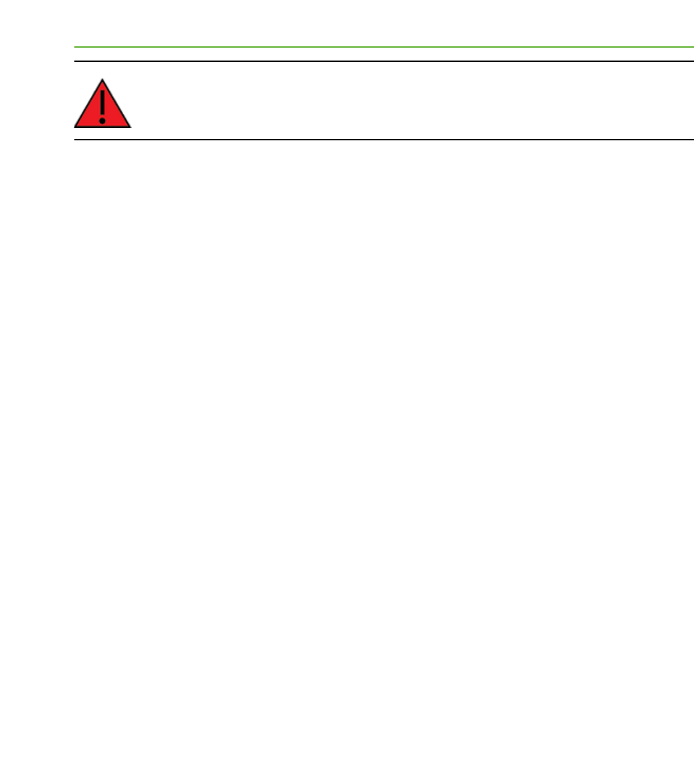
For serial communication to occur, you must configure the UART of both devices with compatible settings
for the baud rate, parity, start bits, stop bits, and data bits. Each data byte consists of a start bit (low), 8
data bits (least significant bit first) and a stop bit (high). The following diagram illustrates the serial bit
pattern of data passing through the device. It shows UART data packet 0x1F (decimal number 31) as
transmitted through the device.
Flow control
XBee/XBee-PRO XTend Compatible (XTC) RF Module User Guide 30
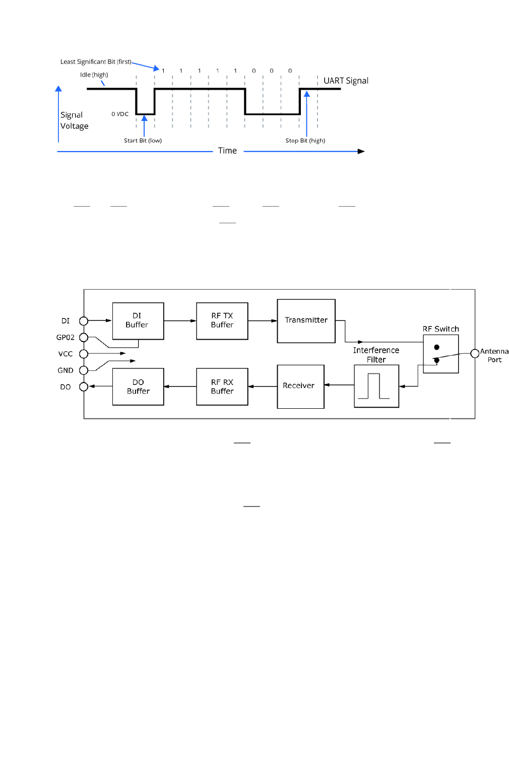
Flow control
The RTS and CTS device pins provide RTS and/or CTS flow control. CTS flow control signals the host to
stop sending serial data to the device. RTS flow control lets the host signal the device so it will not send
the data in the serial transmit buffer out the UART. The following diagram shows the internal data flow,
with the five most common pin signals.
The firmware has Hardware flow control (CTS) configured by default. You must configure CTSflow control
on the host side for it to work.
You must configure Software flow control (XON) on both the host and device side for it to work.
If you change the CS command from 0, then CTSflow control will not work even if you have it configured
on the host.
Data In (DIN) buffer and flow control
When serial data enters the device through the DIN pin (pin 4), it stores the data in the DIN buffer until it
can process the data.
When the firmware satisfies the RB and RO parameter thresholds, the device attempts to initialize an RF
transmission. If the device is already receiving RF data, it stores the serial data in the device's DIN buffer.
The device creates and transmits data packets when it meets one of the following conditions:

Flow control
XBee/XBee-PRO XTend Compatible (XTC) RF Module User Guide 31
1. The device does not receive any serial characters for the amount of time set with in the
RO command; see RO (Packetization Timeout) on page 81.
2. The device receives the maximum number of characters that fits in an RF packet.
3. The device receives the Command Mode sequence; see Enter Command mode on page 21.
If the DIN buffer becomes full, you must implement hardware or software flow control in order to prevent
overflow (loss of data between the host and the device). To eliminate the need for flow control:
1. Send messages that are smaller than the DIN buffer size. The size of the DIN buffer varies
according to the packet size (PK parameter) and the parity setting (NB parameter) you
use.
2. Interface at a lower baud rate (BD parameter) than the RF data rate (BR parameter).
In the following situations, the DIN buffer may become full and overflow:
1. If you set the serial interface data rate higher than the RF data rate of the device, the
device receives data from the host faster than it can transmit the data over-the-air.
2. If the device receives a continuous stream of RF data or if the device monitors data on a
network, it places any serial data that arrives on the DIN pin (pin 4) in the DIN buffer. It
transmits the data in the DIN buffer over-the-air when the device no longer detects RF
data in the network.
Hardware flow control (CTS)
The firmware asserts CTS before the DIN buffer is full so it has time to send the signal and the host has
time to stop sending data.
When the DIN buffer is full, the firmware de-asserts CTS (high) to signal the host to stop sending data;
refer to FT (Flow Control Threshold) on page 79 and CS (GP01 Configuration) on page 77.
The firmware re-asserts CTS after the DIN buffer has 34 bytes of memory available.
Software flow control (XON/OFF)
Use FL to enable XON/XOFF software flow control. This option only works with ASCII data.
Data Out (DO) buffer and flow control
When a device receives RF data, the data enters the DOUT buffer and the device sends it out the serial
port to a host device. Once the DOUT buffer reaches capacity, it loses any additional incoming RF data. The
DOUT buffer stores at least 2.1 kB.
In the following situations, the DOUT buffer may become full and overflow:
1. If you set the interface data rate higher than the RF data rate of the device, the receiving
device receives data from the transmitting device faster than it can send the data to the

Flow control
XBee/XBee-PRO XTend Compatible (XTC) RF Module User Guide 32
host.
2. If the host does not allow the device to transmit data out from the DOUT buffer because
of being held off by hardware or software flow control.

XBee/XBee-PRO XTend Compatible (XTC) RF Module User Guide 33
Configure the XTC RF Module
Configure the device using XCTU
XBee Configuration and Test Utility (XCTU) is a multi-platform program that enables developers to
interact with Digi radio frequency (RF) devices through a graphical interface. The application includes built-
in tools that make it easy to set up, configure, and test Digi RF devices.
For full support of the XTC RF Module, you must use XCTU version 6.3.0 or higher.
For instructions on downloading and using XCTU, go to:
http://www.digi.com/products/xbee-rf-solutions/xctu-software/xctu

XBee/XBee-PRO XTend Compatible (XTC) RF Module User Guide 34
Program the XTC RF Module
XTC RF Module programming examples
For steps on sending AT commands to a device, refer to:
lSend AT commands on page 22
lExit Command mode on page 22
Refer to the online help for XCTU for more information on the program and how to use it. The help
information is available at:
https://docs.digi.com/display/XCTU/XCTU+Overview
Connect the device to a PC
The programming examples that follow require the installation of XCTU and a serial connection to a PC.
Digi stocks connector boards to facilitate interfacing with a PC.
1. Download XCTU from Digi’s website:
http://www.digi.com/products/xbee-rf-solutions/xctu-software/xctu#resources
2. After the .exe file downloads to the PC, double-click the file to launch the XCTU Setup
Wizard. Follow the steps in the wizard to completely install XCTU.
3. Mount the device to an interface board, then connect the assembly to a PC.
4. Launch XCTU and click the Add devices tab on the upper left corner of the screen.
5. Verify that the baud rate and parity settings of the Serial/USB port match those of the
device.
Note Failure to enter Command mode is commonly due to baud rate mismatch. Ensure
that the Baud Rate: setting on the Add radio device window matches the
interface data rate of the device. By default, the BD parameter = 9600 b/s.

XTC RF Module programming examples
XBee/XBee-PRO XTend Compatible (XTC) RF Module User Guide 35
Modify a device address
The following programming example shows you how to modify the device's destination address.
1. Once you add the device in XCTU, click on it in the Radio Modules pane to display the
Configuration working mode. This mode shows most of the device’s parameters that you
can edit.
2. Scroll down in the Radio Configuration pane until you find the parameter you want to edit,
in this case the DT (Destination Address) parameter, or use the search box and type DT.
XCTU automatically scrolls to the selected parameter.
3. When you locate the parameter, change its value, for example to 1A0D. If you do not save
the parameter, the color of the surrounding container is light green.
4. Click the write button to save the value to non-volatile memory; it is the pencil icon to the
right of the parameter . If you change other parameters but have not saved them, you
can use the Write radio settings button to save them. It is the white and blue pencil icon
on the top of the configuration panel .
Restore device defaults
The following programming example shows you how to restore a device's default parameters.
1. After establishing a connection between the device and a PC click the Configuration
working mode tab of XCTU .
2. Click the Load default firmware settings button and agree to restore the default values.
The button is the factory icon .
3. The restored parameters have a light green surrounding color, which means that they
have been changed but not saved.
4. Click the Write module settings button to save all of the parameters simultaneously.
5. All the parameters surrounding box must change to gray indicating that their values are
now saved in the device's non-volatile memory.
Send binary commands
Example: use XCTU's Serial Console tool to change the device's DT (Destination Address) parameter and
save the new address to non-volatile memory.
This example requires XCTU and a serial connection to a PC.
To send binary commands:
1. Set the RT command to 1 to enable binary command programming; do this in Command
mode or configure it through XCTU.

XTC RF Module programming examples
XBee/XBee-PRO XTend Compatible (XTC) RF Module User Guide 36
2. Drive pin 2910 high to assert CMD. To accomplish this, de-assert the RTS line in XCTU. The
device enters Binary Command mode.
3. Send hexadecimal bytes (parameter bytes must be 2 bytes long). The next four lines are
examples, not required values:
00 (Send binary command DT)
0D (Least significant byte of parameter bytes)
1A (Most significant byte of parameter bytes)
08 (Send binary command WR)
4. Drive pin 2910 low to de-assert CMD. After you send the commands, CTS (pin 259) will de-
assert (driven low) temporarily. The device exits Binary Command mode.
The default flow control is NONE, so if you are using XCTU, you should not need to worry about CTS.
However, you can still observe the behavior of the CTS line by monitoring the CTS indicator in the terminal
or console.
Query binary commands
Example: use XCTU's Serial Console tool to query the device's DT (Destination Address) and DB (Received
Signal strength) parameters. In order to query a parameter instead of setting it, you must logically OR the
binary command byte with 0x80.
1. Set the RT command to 1 to enable binary command programming. To do this, you must
either be in Command mode or use XCTU to configure the device.
2. Assert CMD by driving pin 29 high. To do this de-assert the RTS line in XCTU.
3. Send hexadecimal bytes:
80 (Binary command DT (0x00) ORed with 0x80)
B6 (Binary command DB (0x36) ORed with 0x80)
4. Read the device's output for the parameter values of the two commands.
5. De-assert CMD by driving pin 29 low. The device exits Binary Command mode.
When querying commands in binary command mode, the output is the least significant byte followed by
the most significant byte and is always represented in hexadecimal values.

XBee/XBee-PRO XTend Compatible (XTC) RF Module User Guide 37
XTC RF Module commands
The following table lists the AT and binary commands in the XTC RF Module firmware and links to the
description of the individual command.
By default, the device expects numerical values in hexadecimal since the default value of the CF (Number
Base) Parameter is 1. Hexadecimal values are designated by the 0x prefix and decimal values by the d
suffix.
AT command Binary command
%V (Board Voltage) on page 45 0x3B (59d)
AM (Auto-set MY) on page 58 0x41 (65d)
AP (API Enable) on page 74 --
AT (Guard Time After) on page 41 0x05 (5d)
BD (Interface Data Rate) on page 74 0x15 (21d)
BR (RF Data Rate) on page 65 0x39 (57d)
BT (Guard Time Before) on page 41 0x04 (4d)
CC (Command Sequence Character) on page 42 0x13 (19d)
CD (GP02 Configuration) on page 76 0x28 (40d)

XBee/XBee-PRO XTend Compatible (XTC) RF Module User Guide 38
AT command Binary command
CF (Number Base) on page 42 --
CN (Exit Command Mode) on page 43 0x09 (9d)
CS (GP01 Configuration) on page 77 0x1F (31d)
CT (Command Mode Timeout) on page 44 0x06 (6d)
DB (Received Signal Strength) on page 46 0x36 (54d)
DT (Destination Address) on page 59 0x00 (0d)
E0 (Echo Off) on page 44 0x0A (10d)
E1 (Echo On) on page 45 0x0B (11d)
ER (Receive Count Error) 0x0F (15d)
FH (Force Wakeup Initializer) on page 83 0x0D (13d)
FL (Software Flow Control) on page 78 0x07 (7d)
FS (Forced Synch Time) on page 66 0x3F (63d)
FT (Flow Control Threshold) on page 79 0x24 (36d)
GD (Receive Good Count) on page 47 0x10 (16d)
HP (Preamble ID) on page 60 0x11 (17d)
HT (Time before Wake-up Initializer) on page 84 0x03 (3d)
HV (Hardware Version) on page 48 --
ID (Network ID) on page 60 0x27 (39d)
XBee/XBee-PRO XTend Compatible (XTC) RF Module User Guide 39
AT command Binary command
KY (AES Encryption Key) on page 73 0x43 (67d)
LH (Wakeup Initializer Timer) on page 84 0x0C (12d)
MD (RF Mode) on page 66 0x31 (49d)
MK (Address Mask) on page 61 0x12 (18d)
MT (Multi-transmit) on page 61 0x3E (62d)
MY (Source Address) on page 62 0x2A (42d)
NB (Parity) on page 79 0x23 (35d)
PB (Polling Begin Address) on page 67 0x45 (69d)
PD (Minimum Polling Delay) on page 68 0x47 (71d)
PE (Polling End Address) on page 68 0x46 (70d)
PK (Maximum RF Packet Size) on page 69 0x29 (41d)
PL (TX Power Level) on page 71 0x3A (58d)
PW (Pin Wakeup) on page 85 0x1D (29d)
RB (Packetization Threshold) on page 80 0x20 (32d)
RC (Ambient Power - Single Channel) on page 48 --
RE (Restore Defaults) on page 49 0x0E (14d)
RM (Ambient Power) on page 50 --
RN (Delay Slots) on page 63 0x19 (25d)

XBee/XBee-PRO XTend Compatible (XTC) RF Module User Guide 40
AT command Binary command
RO (Packetization Timeout) on page 81 0x21 (33d)
RP (RSSI PWM Timer) on page 51 0x22 (34d)
RR (Retries) on page 64 0x18 (24d)
RT (GPI1 Configuration) on page 82 0x16 (22d)
SB (Stop Bits) on page 82 0x37 (55d)
SH (Serial Number High) on page 52 0x25 (37d)
SL (Serial Number Low) on page 52 0x26 (38d)
SM (Sleep Mode) on page 86 0x01 (1d)
ST (Time before Sleep) on page 87 0x02 (2d)
TP (Board Temperature) on page 53 0x38 (56d)
TR (Transmit Error Count) on page 53 0x1B (27d)
TT (Streaming Limit) on page 64 0x1A (26d)
TX (Transmit Only) on page 72 0x40 (64d)
VL (Firmware Version - Verbose) on page 54 --
VR (Firmware Version - Short) on page 54 0x14 (20d)
WA (Active Warning Numbers) on page 55 --
WN (Warning Data) on page 56 --
WR (Write) on page 88 0x08 (8d)

Command mode options
XBee/XBee-PRO XTend Compatible (XTC) RF Module User Guide 41
AT command Binary command
WS (Sticky Warning Numbers) on page 58 --
Command mode options
The following AT commands are Command mode option commands.
AT (Guard Time After)
Sets or reads the time-of-silence that follows the CC (Command Sequence Character) of the Command
mode sequence (BT + CC + AT). By default, one second must elapse before and after the command
sequence character.
The times-of-silence surrounding the Command Sequence Character prevent the device from
inadvertently entering Command mode.
Binary command
0x05 (5 decimal)
Command type
Command mode options
Parameter range
2 - (ST-3) up to 0x1770 [x 100 ms]
Default
0xA (1 second)
Bytes returned
2
BT (Guard Time Before)
Sets the DI pin silence time that must precede the Command Sequence Character (CC command) of the
Command mode sequence. For more information about the Command mode sequence, see Enter
Command mode on page 21.
Binary command
0x04 (4 decimal)

Command mode options
XBee/XBee-PRO XTend Compatible (XTC) RF Module User Guide 42
Command type
Command mode options
Parameter range
0 - 0x1770 [x 100ms]
Default
0x0A (1 second)
Bytes returned
2
CC (Command Sequence Character)
The ASCII character value you use to enter Command mode. Use CC to set or read the character used
between guard times of the Command mode sequence (BT + CC + AT). This sequence enters the device
into Command mode so that device recognizes data entering it from the host as commands instead of
payload data.
Binary command
0x13 (19 decimal)
Command type
Command mode options
Parameter range
0x20 - 0x7F
Default
0x2B (ASCII “+”)
Bytes returned
1
CF (Number Base)
Sets or reads the command formatting setting.
The firmware always enters and reads the following commands in hex, no matter what the CF setting is:

Command mode options
XBee/XBee-PRO XTend Compatible (XTC) RF Module User Guide 43
VR (Firmware Version)
HV (Hardware Version)
KY (AES Encryption Key)
Binary command
N/A
Command type
Command mode options
Parameter range
0 - 2
Parameter Configuration
0 Commands use the default number base; decimal commands may output units.
1 All commands are forced to unsigned, unit-less hex.
2 Commands use their default number base; no units are output.
Default
1
Bytes returned
1
CN (Exit Command Mode)
Makes the device exit Command mode.
Binary command
0x09 (9 decimal)
Command type
Command mode options

Command mode options
XBee/XBee-PRO XTend Compatible (XTC) RF Module User Guide 44
Parameter range
N/A
Default
N/A
Bytes returned
N/A
CT (Command Mode Timeout)
Set or read the Command mode timeout parameter. If a device does not receive any valid commands
within this time period, it returns to Idle mode from Command mode.
Use the CN (Exit Command mode) command to exit Command mode manually.
Binary command
0x06 (6 decimal)
Command type
Command mode options
Parameter range
2 - 0x53E2 [x 100 milliseconds]
Default
0xC8 (20 seconds)
Bytes returned
2
E0 (Echo Off)
Turns off the character echo in Command mode.
By default, echo is off.
Binary command
0x0A (10 decimal)

Diagnostic commands
XBee/XBee-PRO XTend Compatible (XTC) RF Module User Guide 45
Command type
Command mode options
Parameter range
N/A
Default
N/A
Bytes returned
N/A
E1 (Echo On)
Enables character echo in Command mode. Each character that you type echoes back to the terminal
when E1 is active. E0 (Echo Off) is the default.
Binary command
0x0B (11 decimal)
Command type
Command mode options
Parameter range
N/A
Default
N/A
Bytes returned
N/A
Diagnostic commands
The following AT commands are diagnostic commands. Diagnostic commands are typically volatile and will
not persist across a power cycle.
%V (Board Voltage)
Reads the supply voltage to the module's VCC (pin 2).

Diagnostic commands
XBee/XBee-PRO XTend Compatible (XTC) RF Module User Guide 46
The conversion of the hex value returned by %V to Volts is VAL/65536 = Volts.
Example:
2.8 VDC = 2.8 * 65536 = 0x2CCCD
3.3 VDC = 3.3 * 65536 = 0x34CCD
Sample output
3.27 V (when CF = 0)
345E3 (when CF = 1) 1
3.27 (when CF = 2)
Binary command
0x3B (59 decimal)
Parameter range
(read-only):
0x26666 - 0x39999 (2.40 to 3.60 V)
Default
N/A
Bytes returned
4
DB (Received Signal Strength)
This command reports the received signal strength indicator (RSSI) of the last RF data packet that a
device receives. It reports the RSSI in decibels relative to milliwatts. DB is useful in determining range
characteristics of the RF devices under various conditions. On XTC, this is accurate from approximately -50
to -100 dBm.
In Transparent operating mode, DB shows the power level in signed decimal format with the units (dBm).
If CF = 1, the magnitude of the value is in unsigned hex. If CF = 2, the value is in decimal, but without the
units.
1When CF = 1 (default), the firmware shows a hex integer that is equal to (voltage * 65536d).

Diagnostic commands
XBee/XBee-PRO XTend Compatible (XTC) RF Module User Guide 47
Sample output
-88 dBm (when CF = 0)
58 (when CF = 1)
-88 (when CF = 2)
Note If the firmware reads the DB register before the device receives an RF packet, the devices returns
a value of 0x8000.
Binary command
0x36 (54 decimal)
Command type
Diagnostics
Parameter range
(read-only): 0x6E - 0x28
(-110 to -40 decimal)
Default
N/A
Bytes returned
2
GD (Receive Good Count)
Sets or reads the number of RF packets with valid MAC headers that the device receives successfully on
the RF interface. When the value reaches 0xFFFF, it stays there until you manually change the maximum
count value or reset the device.
Its parameter value is reset to 0 after every device reset and is not non-volatile; the parameter value does
not persist in the device's memory after a power-up sequence.
Pin, serial port or cyclic sleep modes do not reset the GD parameter.
Binary command
0x10 (16 decimal)

Diagnostic commands
XBee/XBee-PRO XTend Compatible (XTC) RF Module User Guide 48
Command type
Diagnostics
Parameter range
0 - 0xFFFF
Default
0
Bytes returned
2
HV (Hardware Version)
Reads the device's hardware version number.
Binary command
N/A
Command type
Diagnostics
Parameter range
(read-only): 0 - 0xFFFF
Default
N/A
Bytes returned
N/A
RC (Ambient Power - Single Channel)
Reads and reports the power level on a given channel.
Sample output
-78 dBm (when CF = 0)
4e (when CF = 1)

Diagnostic commands
XBee/XBee-PRO XTend Compatible (XTC) RF Module User Guide 49
-78 (when CF = 2)
Binary command
N/A
Parameter range
(read-only): 0 - 0x31 [dBm]
Default
N/A
Bytes returned
1
RE (Restore Defaults)
Restore device parameters to factory defaults.
RE does not cause the device to store default values to non-volatile (persistent) memory. You must send
the WR command prior to power-down or reset to save the default settings in the device's non-volatile
memory.
Binary command
0x0E (14 decimal)
Command type
Diagnostics
Parameter range
N/A
Default
N/A
Bytes returned
N/A

Diagnostic commands
XBee/XBee-PRO XTend Compatible (XTC) RF Module User Guide 50
RM (Ambient Power)
Reads and reports power levels on all channels. If you do not provide a parameter, the device scans the
channels one time. If you do provide a parameter, the device scans the channels repeatedly for the
number of seconds that the parameter calls for. The firmware reports the maximum power level seen for
each channel (in other words, peak hold).
To implement a graphical spectrum analyzer, repeatedly send RM with no arguments and read the
resulting 50 power levels. This is easiest to do when CF = 1 or 2.
Sample output when CF = 0: Ch 0: -100 dBm
Ch 1: -103 dBm
...
Ch 49: -99 dBm
Sample output when CF = 1: 64 64
67
...
63
Sample output when CF = 2: 100 100
-103
...
-99
Binary command
N/A

Diagnostic commands
XBee/XBee-PRO XTend Compatible (XTC) RF Module User Guide 51
Command type
Diagnostics
Parameter range
no parameter - 0x7D0
Default
N/A
Bytes returned
2
RP (RSSI PWM Timer)
Enables a pulse-width modulated (PWM) output on the RSSI pin (pin 7 of the device). We calibrate the pin
to show the difference between received signal strength and the sensitivity level of the device. PWM
pulses vary from zero to 95 percent. Zero percent means the RF signal the device receives is at or below
the device's sensitivity level.
The following table shows dB levels above sensitivity and PWM values. The total time period of the PWM
output is 8.32 ms PWM output consists of 40 steps and therefore the minimum step size is 0.208 ms.
dB above sensitivity PWM percentage (high period / total period)
10 30%
20 45%
30 60%
A non-zero value defines the time that PWM output is active with the RSSI value of the last RF packet the
device receives. After the set time when the device has not received RF packets, it sets the PWM output
low (0 percent PWM) until the device receives another RF packet. It also sets PWM output low at power-
up. A parameter value of 0xFF permanently enables PWM output and always reflects the value of the last
received RF packet.
Binary command
0x22 (34 decimal)

Diagnostic commands
XBee/XBee-PRO XTend Compatible (XTC) RF Module User Guide 52
Parameter range
0 - 0xFF [x 100 milliseconds]
Default
0x20 (3.2 seconds)
Bytes returned
1
SH (Serial Number High)
Sets or reads the device's serial number high word.
Binary command
0x25 (37 decimal)
Command type
Diagnostics
Parameter range
0 - 0xFFFF
Default
Varies
Bytes returned
2
SL (Serial Number Low)
Sets or reads the serial number low word of the device.
Binary command
0x26 (38 decimal)
Command type
Diagnostics

Diagnostic commands
XBee/XBee-PRO XTend Compatible (XTC) RF Module User Guide 53
Parameter range
(read-only): 0 - 0xFFFF
Default
Varies
Bytes returned
2
TP (Board Temperature)
The current module temperature in degrees Celsius in 8-bit two’s compliment format. For example 0x1A =
26°C, and 0xF6 = -10°C.
Sample output
26 C when CF = 0
1A when CF = 1
26 when CF = 2
Binary command
0x38 (56 decimal)
Parameter range
(read-only) 0 - 0x7F
Default
N/A
Bytes returned
1
TR (Transmit Error Count)
Reads the number of RF packets where retries expire without receiving an ACK (when RR > 0).
This count increments whenever a MAC transmission attempt exhausts all MAC retries without ever
receiving a MAC acknowledgment message from the destination node. Once the number reaches 0xFFFF,
it does not count further events. To reset the counter to any 16-bit value, append a hexadecimal
parameter to the command.

Diagnostic commands
XBee/XBee-PRO XTend Compatible (XTC) RF Module User Guide 54
This value is volatile (the value does not persist in the device's memory after a power-up
sequence).
Binary command
0x1B (27 decimal)
Parameter range
0 - 0xFFFF
Default
0
Bytes returned
2
VL (Firmware Version - Verbose)
Reads the verbose firmware version of the device.
Binary command
N/A
Parameter range
Returns a string
Default
0
Bytes returned
2
VR (Firmware Version - Short)
Reads the firmware version on a device.
Firmware versions contain four significant digits: A.B.C.D. If B = 2, the device is programmed for operation
in Australia only.
Binary command
0x14 (20 decimal)

Diagnostic commands
XBee/XBee-PRO XTend Compatible (XTC) RF Module User Guide 55
Command type
Diagnostics
Parameter range
(read-only): 0 - 0xFFFF
Default
N/A
Bytes returned
2
WA (Active Warning Numbers)
Reports the warning numbers of all active warnings, one warning number per line. It does not show
further information and does not reset warning counts. For information on what the warning numbers
mean, see WN (Warning Data) on the next page.
Sample output (indicates warnings 1 and 3 are currently active)
1
3
OK
Binary command
N/A
Command type
Diagnostics
Parameter range
Returns a string: one warning number per line.
Default
N/A
Bytes returned
N/A

Diagnostic commands
XBee/XBee-PRO XTend Compatible (XTC) RF Module User Guide 56
WN (Warning Data)
Reports the following data for all active and sticky warnings:
lWarning number and description
lNumber of occurrences since the last WN or WS command
lWhether the warning is currently active
WN does not display warnings that are not currently active and have not been active since the last
issuance of the WN or WS commands. WN resets all non-zero warning counts except for warnings that are
presently active, which are set to 1.
Sample output
Warning 4: Over-temperature
5 occurrences; presently inactive.
Warning
#
Description
1 Under-voltage. This is caused if the supply voltage falls below the minimum threshold for
the lowest power level (2.8 V). If/when the voltage rises above the threshold, the warning
is deactivated. The device does not transmit below this voltage threshold.
2 Deprecated.
3 Under-temperature. This is caused if the temperature sensed by the device is less than -
40° C. The device does not artificially limit operation while this warning is active, but device
functionality is not guaranteed.
4 Over-temperature. This is caused if the temperature sensed by the device is greater than
105° C. The device does not allow transmission nor reception while this warning is active.
The warning is deactivated when the temperature falls below 100° C.
5 Deprecated.
6 Deprecated.

Diagnostic commands
XBee/XBee-PRO XTend Compatible (XTC) RF Module User Guide 57
Warning
#
Description
7 Default configuration parameters in flash. This is caused if user-modifiable parameters (i.e.
those stored by WR) in flash are all the compiled-in default values. This is caused if the user
configuration is found to be not present or invalid at power-up and there is no custom
configuration, or if no user-modifiable parameters have been modified from the compiled-
in defaults. Modification of one or more parameters without the subsequent WR to commit
the changes to flash will not deactivate this warning, since it reflects the status of the
parameters in flash. This warning does not reflect usage of the custom configuration
defaults, only usage of the compiled-in defaults.
8 Default factory configuration parameters in flash. This is caused if the factory parameters
in flash are all the default values. This is caused if the factory configuration is found to be
not present or invalid at power-up, or if no factory parameters have been modified.
9 Watchdog reset occurred.
10 PK was reduced by BR.
11 RB was reduced by PK.
12 One or more parameters overridden due to conflict.
Binary command
N/A
Command type
Diagnostics
Parameter range
Returns a string
Default
N/A
Bytes returned
N/A

MAC/PHY commands
XBee/XBee-PRO XTend Compatible (XTC) RF Module User Guide 58
WS (Sticky Warning Numbers)
Reports warning numbers of all warnings active since the last use of WS or WN, including any warnings
that are currently active. WS also resets all non-zero warning counts, except for warnings that are
presently active, which are set to 1.
Binary command
N/A
Command type
Diagnostics
Parameter range
(read-only): 1 - 8
Default
N/A
Bytes returned
1
MAC/PHY commands
The following AT commands are MAC/PHY commands.
AM (Auto-set MY)
Sets the MY (Source Address) parameter from the factory-set serial number of the device. The address
consists of bits 29, 28 and 13-0 of the serial number, in that order.
Sending AM displays the address.
Binary command
0x41 (65 decimal)
Command type
MAC/PHY
Parameter range
N/A

MAC/PHY commands
XBee/XBee-PRO XTend Compatible (XTC) RF Module User Guide 59
Default
N/A
Bytes returned
N/A
DT (Destination Address)
Sets or reads the networking address of a device. The devices use three filtration layers:
lVendor ID Number (ATID)
lChannel (ATHP)
lDestination Address (ATDT)
The DT command assigns an address to a device that enables it to communicate with other devices in the
network. The simplest use of this command is that when MY=0xFFFF and MK=0xFFFF on all devices in a
network, only devices with matching DT's communicate with each other.
If MY is not 0xFFFF, then DT acts as a transmit address and MY acts as a receive address. For example, you
can set MY to unique values 1, 2, 3, and so forth on unique devices in the network. Then set DT on the
transmitting device to match the MY of the receiving device you intend to communicate with.
Setting DT=0xFFFF broadcasts to all devices in the network. For more information, see Addressing on
page 103.
Binary command
0x00 (0 decimal)
Command type
MAC/PHY
Parameter range
0 - 0xFFFF
Default
0
Bytes returned
2

MAC/PHY commands
XBee/XBee-PRO XTend Compatible (XTC) RF Module User Guide 60
HP (Preamble ID)
Set or read the device's hopping channel number. A channel is one of three layers of filtration available to
the device.
In order for devices to communicate with each other, the devices must have the same channel number
since each channel uses a different hopping sequence. Devices can use different channels to prevent
devices in one network from listening to transmissions of another.
When a device receives a packet it checks HP before the network ID, as it is encoded in the preamble and
the network ID is encoded in the MAC header.
Binary command
0x11 (17 decimal)
Parameter range
0 - 9
Default
0
Bytes returned
1
ID (Network ID)
Sets or reads the Vendor Identification Number (VID) of the device. Devices must have matching VIDs in
order to communicate. If the device uses OEM network IDs, 0xFFFF uses the factory value.
Binary command
0x27 (39 decimal)
Parameter range
0x11 - 0x7FFF (user-settable)
0 - 0x10 and 0x8000 - 0xFFFF (factory-set)
Default
0x3332

MAC/PHY commands
XBee/XBee-PRO XTend Compatible (XTC) RF Module User Guide 61
Bytes returned
2
MK (Address Mask)
Sets or read the device's Address Mask.
All RF data packets contain the Destination Address of the transmitting (TX) device. When a device
receives a packet, the TX device's Destination Address is logically combined bitwise (in other words, joined
with AND) with the Address Mask of the receiving (RX) device. The resulting value must match the
Destination Address or Address Mask of the RX device for the packet to be received and sent out the RX
device's DO (Data Out) pin. If the combined value does not match the Destination Address or Address Mask
of the RX device, it discards the packet.
Sniffer mode (when MK = 0): the device ignores ACK requests and sends every RX (receive) frame out the
UART, without regard for repeated frames.
The firmware treats all 0 values as irrelevant and ignores them. For more information, see Addressing on
page 103.
Binary command
0x12 (18 decimal)
Command type
MAC/PHY
Parameter range
0 - 0xFFFF
Default
0xFFFF
Bytes returned
2
MT (Multi-transmit)
Enables multiple transmissions of RF data packets. When you enable Multi-transmit mode (MT > 0),
packets do not request an ACK from the receiving devices. MT takes precedence over RR, so if both MT
and RR are non-zero, then a device sends MT+1 packets with no ACK requests.

MAC/PHY commands
XBee/XBee-PRO XTend Compatible (XTC) RF Module User Guide 62
When a receiving device receives a packet with remaining forced retransmissions, it calculates the length
of the packet and inhibits transmission for the amount of time required for all retransmissions. From that
time on, the device inserts a random number of delay slots between 0 and RN before allowing
transmission from the receiving devices. This prevents all listening devices from transmitting at once upon
conclusion of a multiple transmission event (when RN > 0).
Note The actual number of forced transmissions is the parameter value plus one. For example, if MT = 1,
a devices sends two transmissions of each packet.
For more information, see Multi-transmit mode on page 105.
Binary command
0x3E (62d)
Command type
MAC/PHY
Parameter range
0 - 0xFF
Default
0 (no forced retransmissions)
Bytes returned
1
MY (Source Address)
Sets or reads the Source Address of a device.
For more information, see DT (Destination Address) on page 59 and Addressing on page 103.
Binary command
0x2A (42 decimal)
Command type
MAC/PHY
Parameter range
0 - 0xFFFF

MAC/PHY commands
XBee/XBee-PRO XTend Compatible (XTC) RF Module User Guide 63
Default
0xFFFF (Disabled - DT (Destination Address) parameter serves as both source and destination
address).
Bytes returned
2
RN (Delay Slots)
Sets or reads the time delay that the transmitting device inserts before attempting to resend a packet. If
the transmitting device fails to receive an acknowledgment after sending a packet, it inserts a random
number of delay slots (ranging from 0 to (RN minus 1)) before attempting to resend the packet. Each delay
slot is 5 msec when BR = 1 and 54 msec when BR = 0.
If two devices attempt to transmit at the same time, the random time delay after packet failure only
allows one device to transmit the packet successfully, while the other device waits until the channel is
available for RF transmission.
RN is only applicable if:
lYou enable retries using the RR command, or
lYou insert forced delays into a transmission using the TT command
Binary command
0x19 (25 decimal)
Command type
MAC/PHY
Parameter range
0 - 0xFF [38 ms delay slots]
Default
0 (no delay slots inserted)
Bytes returned
1

MAC/PHY commands
XBee/XBee-PRO XTend Compatible (XTC) RF Module User Guide 64
RR (Retries)
Sets or reads the maximum number of retries sent for a given RF packet. When you enable RR (RR > 0), it
enables RF packet retries and ACKs.
Exceptions: If you enable the MT command (MT > 0) or if you use a broadcast destination address (DT =
0xFFFF) it disables RF packet retries and ACKs.
After transmitting a packet, the transmitting device waits to receive an ACK from a receiving device. If it
does not receive the ACK in the time that RN specifies, it transmits the original packet again. The
transmitting device transmits the RF packet repeatedly until it receives an ACK or until it sends the packet
RR times.
Binary command
0x18 (24 decimal)
Command type
MAC/PHY
Parameter range
0 - 0xFF
Default
0x0A (10 decimal)
Bytes returned
1
TT (Streaming Limit)
Sets or reads the limit on the number of bytes that a device can send before issuing a random delay.
If a device is sending a continuous stream of RF data, it inserts a delay that stops its transmission and
gives other devices time to transmit once it sends TT bytes of data. The random delay it inserts lasts
between 1 and RN + 1 delay slots.
You can use TT to simulate full-duplex behavior.
Binary command
0x1A (26 decimal)

RF interfacing commands
XBee/XBee-PRO XTend Compatible (XTC) RF Module User Guide 65
Command type
MAC/PHY
Parameter range
0 - 0xFFFF [bytes]
Default
0
Bytes returned
2
RF interfacing commands
The following AT commands are RF interfacing commands.
BR (RF Data Rate)
Sets and reads the device's RF data rate (the rate that the device transmits RF data over-the-air).
Binary command
0x39 (57 decimal)
Parameter range
0 - 1
Parameter RF data rate
0 10 kb/s
1 125 kb/s
Default
1
Bytes returned
1

RF interfacing commands
XBee/XBee-PRO XTend Compatible (XTC) RF Module User Guide 66
FS (Forced Synch Time)
The FS command only applies to streaming data. Normally, only the first packet of a continuous stream
contains the full RF initializer. The RF devices then remain synchronized for subsequent packets of the
stream.
You can use this parameter to periodically force an RF initializer during such streaming. Any break in UART
character reception that is long enough to drain the DI buffer and cause a pause in RF data transmission
also causes the firmware to insert an RF initializer on the next transmission.
Binary command
0x3F (63 decimal)
Command type
RF interfacing
Parameter range
0 - 0xFFFF
[x 10 milliseconds]
Default
0
Bytes returned
2
MD (RF Mode)
Sets or reads the settings that enable the Polling and Repeater modes on the device.
Polling Mode: a Polling Base is responsible for polling remotes. A Polling Remote requires a poll from a
Polling Base in order to transmit.
Repeater Mode: a Repeater re-sends RF data unless the transmission is addressed to it or if it has already
detected the transmission. A Repeater End Node handles repeated messages, but will not repeat the
message over-the-air.
For more information, see Basic communications on page 104.
Binary command
0x31 (49 decimal)

RF interfacing commands
XBee/XBee-PRO XTend Compatible (XTC) RF Module User Guide 67
Command type
RF interface
Parameter range
0 - 6
Parameter Configuration
0 Transparent Operation (Repeater Base)
1 Reserved - not used
2 Reserved - not used
3 Polling Base
4 Polling Remote
5 Repeater
6 Repeater End Node
Default
0
Bytes returned
1
PB (Polling Begin Address)
Sets or reads the device’s Polling Begin Address, which is the first address polled when you enable Polling
mode.
Binary command
0x45 (69 decimal)
Command type
RF interface

RF interfacing commands
XBee/XBee-PRO XTend Compatible (XTC) RF Module User Guide 68
Parameter range
0 - 0xFFFF
Default
0
Bytes returned
2
PD (Minimum Polling Delay)
Sets or reads the Polling Delay (Base, MD = 3) or Polling Timeout (Remote, MD = 4).
Polling Delay (Base) is the time between polling cycles. The Polling Base starts the polling cycle after
sending the first poll. After the polling cycle completes, the timer restarts.
Polling Timeout (Remote) is the amount of time the remote device holds data from the serial port before
discarding it. The device transmits data entered within the PD time of the poll and does not discard it.
Binary command
0x47 (71 decimal)
Command type
RF interface
Parameter range
0 - 0xFFFF (Base: [x 1ms], Remote: [x 10ms])
Default
0x64
Bytes returned
2
PE (Polling End Address)
Sets or reads the device’s Polling End Address; which is the last address polled when you enable Polling
mode.

RF interfacing commands
XBee/XBee-PRO XTend Compatible (XTC) RF Module User Guide 69
Binary command
0x46 (70 decimal)
Command type
RF interface
Parameter range
0 - 0xFFFF
Default
0
Bytes returned
2
PK (Maximum RF Packet Size)
Sets or reads the maximum size of RF packets that a device in Transparent operating mode (AP = 0)
transmits. You can use the maximum packet size along with the RB and RO parameters to implicitly set
the channel dwell time.
If you set PK above 256 and subsequently change BR to 0, PK lowers to 256 and issues a warning. For
more information, see BR (RF Data Rate) on page 65 and WN (Warning Data) on page 56.
Changes to the PK parameter may have a secondary effect on the RB (Packetization Threshold)
parameter. RB must always be less than or equal to PK. If you change PK to a value that is less than the
current value of RB, the RB value lowers to be equal to PK.
Binary command
0x29 (41 decimal)
Command type
RF interfacing
Parameter range
1 - 0x800 [Bytes]

RF interfacing commands
XBee/XBee-PRO XTend Compatible (XTC) RF Module User Guide 70
Default
0x100 (BR=0) 0x800 (BR=1)1
Bytes returned
2
1When BR = 0 (9600 baud), the maximum PK value is 0x100 (256 bytes). When BR = 1 (115,200 baud), the maximum
PK value is 0x800 (2048 bytes).

RF interfacing commands
XBee/XBee-PRO XTend Compatible (XTC) RF Module User Guide 71
PL (TX Power Level)
Sets or reads the power level at which the device transmits conducted power.
The PRO XTC device requires the power supply to be above 3.3 V to ensure 30 dBm output power. The
following table shows the typical values over supply voltage.
Power supply Output power
3.3 to 3.6 V 30 dBm typical
3.0 V 29 dBm typical
2.6 V 27 dBm typical
Binary command
0x3A (58 decimal)
Command type
RF interfacing
Parameter range
0 - 4
XB9XT (non-PRO) XBP9XT (PRO)
Parameter Configuration Configuration
PL0 0 dBm 20 dBm1
PL1 10 dBm
PL2 13 dBm
PL3 13 dBm 27 dBm
1We do not recommend the 20 dBm power level when operating at temperatures below 0°C. Output power may
vary significantly below 0°C.

RF interfacing commands
XBee/XBee-PRO XTend Compatible (XTC) RF Module User Guide 72
XB9XT (non-PRO) XBP9XT (PRO)
Parameter Configuration Configuration
PL4 13 dBm 30 dBm (1 Watt)
Default
4
Bytes returned
1
TX (Transmit Only)
Sets or reads the transmit or receive behaviors of the device. Setting a device to TX-only (TX = 1) may
reduce latency because the you can not limit the transmitting device to receiving data from other devices.
Binary command
0x40 (64d)
Command type
RF Interfacing
Parameter range
0 - 1
Parameter Description
0 TX and RX
1 TX only
Default
0
Bytes returned
1

Security commands
XBee/XBee-PRO XTend Compatible (XTC) RF Module User Guide 73
Security commands
The following AT commands are security commands.
KY (AES Encryption Key)
Sets the 256-bit Advanced Encryption Standard (AES) key for encrypting or decrypting data. Once set, you
cannot read the key cannot out of the device by any means. The firmware encrypts the entire payload of
the packet using the key and computes the CRC across the ciphertext. When you enable encryption, each
packet carries an additional 16 bytes to convey the random cipher-block chaining (CBC) Initialization
Vector (IV) to the receiver(s). The KY value may be 0 or any 256-bit value (= 64 hex digits = 32 bytes). Any
other value, including entering ATKY by itself with no parameters, causes an error.
A device with the wrong key (or no key) receives encrypted data, but the data driven out the serial port is
meaningless. Likewise, a device with a key receives unencrypted data sent from a device without a key,
but the output is meaningless. Because it uses CBC mode, repetitive data appears differently in different
transmissions due to the randomly-generated IV.
Note For international (non-U.S.) variants of XTC devices, the encryption key is 128-bit AES. The
command operates the same except the key length is 16 bytes rather than 32 bytes. This
pertains to part numbers ending with 128, no matter which firmware version is loaded. This also
pertains to the Australia version of firmware 22xx.
Binary command
0x43 (67d)
Command type
Security
Parameter range
0 - (64 hex digits all set to 'F')
Default
0 (disabled)
Bytes returned
2
Serial interfacing commands
The following AT commands are serial interfacing commands.

Serial interfacing commands
XBee/XBee-PRO XTend Compatible (XTC) RF Module User Guide 74
AP (API Enable)
The API mode setting. The device can format the RF packets it receives into API frames and send them out
the serial port.
When you enable API, you must format the serial data as API frames because Transparent operating mode
is disabled.
Binary command
N/A
Parameter range
0-2
Parameter Description
0 Transparent Mode. All UART input and output is raw data and the device uses the RO
parameter to delineate packets.
1 API Mode Without Escapes. The device packetizes all UART input and output data in API
format, without escape sequences.
2 API Mode With Escapes. The device is in API mode and inserts escaped sequences to
allow for control characters. The device passes 0x11, 0x13, 0x7d, and 0x7e as data.
Default
0
Bytes returned
1
BD (Interface Data Rate)
Sets and reads the serial interface data rate (baud rate) between the device and the host. The baud rate
is the rate that the host sends serial data to the device.
When you make an update to the interface data rate, the change does not take effect until the host issues
the CN command and the device returns the OK response.

Serial interfacing commands
XBee/XBee-PRO XTend Compatible (XTC) RF Module User Guide 75
The BD parameter does not affect the RF data rate. If you set the interface data rate higher than the RF
data rate, you may need to implement a flow control configuration.
The range between standard and non-standard baud rates (0x9 - 0x4B0) is invalid. The range between
0x2580 and 0x4AFF is also invalid.
Non-standard interface data rates
The firmware interprets any value within 0x4B0 - 0x2580 and 0x4B00 - 0x1C9468 as an actual baud rate.
When the host sends a value above 0x4B0, the firmware stores the closest interface data rate
represented by the number in the BD register. For example, to set a rate of 19200 b/s, send the following
command line: ATBD4B00.
Note When using XCTU, you can only set and read non-standard interface data rates using the XCTU
Serial Console tool. You cannot access non-standard rates through the configuration section of
XCTU.
Note The device does not support nonstandard baud rates between 9601 and 19199 baud. If you
attempt to set baud rates in this range, it will return an error.
When you send the BD command with a non-standard interface data rate, the UART adjusts to
accommodate the interface rate you request. In most cases, the clock resolution causes the stored BD
parameter to vary from the sent parameter. Sending ATBD without an associated parameter value
returns the value actually stored in the device’s BD register.
The following table provides the parameters sent versus the parameters stored.
BD parameter sent (HEX) Interface data rate (b/s) BD parameter stored (HEX)
0 1200 0
4 19,200 4
7 115,200 7
1C200 115,200 1B207
Binary command
0x15 (21 decimal)
Command type
Serial Interfacing

Serial interfacing commands
XBee/XBee-PRO XTend Compatible (XTC) RF Module User Guide 76
Parameter ranges
0 - 8 (standard rates)
0x4B0 - 0x1C9468 (non-standard rates; ; 0x2581 to 0x4AFF not supported)
Parameter Configuration (b/s)
0 1200
1 2400
2 4800
3 9600
4 19200
5 38400
6 57600
7 115200
8 230400
Default
3
Bytes returned
4
CD (GP02 Configuration)
Selects or reads the behavior of the GPO2 line (pin 5).
Binary command
0x28 (40 decimal)

Serial interfacing commands
XBee/XBee-PRO XTend Compatible (XTC) RF Module User Guide 77
Parameter range
0 - 4
Parameter Configuration
0 RXLED
1 Static high
2 Static low
3 Reserved
4 RX LED (valid address only)
Default
2
Bytes returned
1
CS (GP01 Configuration)
Sets or reads the behavior of the GPO1 line (pin 25). This output can provide RS-232 flow control and
controls the TX enable signal for RS-485 or RS-422 operations.
By default, GP01 provides RS-232 Clear-to-Send (CTS) flow control.
Binary command
0x1F (31 decimal)
Parameter range
0 - 4
Parameter Configuration
0 RS-232 CTS flow control

Serial interfacing commands
XBee/XBee-PRO XTend Compatible (XTC) RF Module User Guide 78
Parameter Configuration
1 RS-485 TX enable low
2 Static high
3 RS-485 TX enable high
4 Static low
Default
0
Bytes returned
1
FL (Software Flow Control)
Configures software flow control. Use the CS and RT commands to implement Hardware Flow Control.
Set FL to 1 to enable Software flow control (XON/XOFF).
Set FL to 0 to disable Software flow control.
The XON character used is 0x11 (17 decimal).
The XOFF character used is 0x13 (19 decimal).
Binary command
0x07 (7 decimal)
Command type
Serial interfacing
Parameter range
0 - 1
Default
0

Serial interfacing commands
XBee/XBee-PRO XTend Compatible (XTC) RF Module User Guide 79
Bytes returned
1
FT (Flow Control Threshold)
Sets or reads the flow control threshold.
De-assert CTS when the number of bytes specified by the FT parameter are in the DIN buffer. Re-assert
CTS when less than FT - 16 bytes are in the UART receive buffer.
Binary command
0x24 (36 decimal)
Parameter range
0x11 - 0xC00 [bytes]
Default
0xBBF (DI buffer size minus 0x11)
Bytes returned
2
NB (Parity)
Set or read the parity settings for UART communications.
Binary command
0x23 (35 decimal)
Command type
Serial interfacing
Parameter range
0 - 4
Parameter Configuration
0 8-bit (no parity or 7-bit (any parity)

Serial interfacing commands
XBee/XBee-PRO XTend Compatible (XTC) RF Module User Guide 80
Parameter Configuration
1 8-bit even
2 8-bit odd
3 8-bit mark
4 8-bit space
Default
0
Bytes returned
1
RB (Packetization Threshold)
Sets or reads the character threshold value.
RF transmission begins after a device receives data in the DIN buffer and meets either of the following
criteria:
lThe UART receives RB characters
lThe UART receive lines detect RO character times of silence after receiving at least 1 byte
of data
If a device lowers PK below the value of RB,RB is automatically lowers to match the PK value.
If RO = 0, the device must receive RB bytes before beginning transmission.
RB and RO criteria only apply to the first packet of a multi-packet transmission. If data remains in the DIN
buffer after the first packet, transmissions continue in a streaming manner until there is no data left in the
DIN buffer.
Binary command
0x20 (32 decimal)
Parameter range
0 - PK parameter value
(up to 0x800 bytes)

Serial interfacing commands
XBee/XBee-PRO XTend Compatible (XTC) RF Module User Guide 81
Default
0x800 (2048 bytes)
Bytes returned
2
RO (Packetization Timeout)
Set or read the number of character times of inter-character silence required before transmission begins.
For information on how ROworks with the RB command, see RB (Packetization Threshold) on the
previous page.
When RO is the transmission-beginning criteria:
The actual time between the reception of the last character from the UART and the beginning of RF
transmission is at least 800 µsec longer than the actual RO time to allow for transmission setup. It is also
subject to 100-200 µsec of additional uncertainty, which could be significant for small values of RO at high
UART bit rates.
The firmware calculates the correct UART character time (10, 11, or 12 bits) based on the following
criteria:
l1 start bit
l8 data bits
l0 or 1 parity bit (as determined by the NB command)
l1 or 2 stop bits (as determined by SB command)
Binary command
0x21 (33 decimal)
Parameter range
0 - 0x53E2 [x UART character times]
Default
3
Bytes returned
2

Serial interfacing commands
XBee/XBee-PRO XTend Compatible (XTC) RF Module User Guide 82
RT (GPI1 Configuration)
Sets or reads the behavior of the GPI1 pin (pin 29) of the device. You can configure the pin to enable Binary
Command mode or RTS flow control.
Binary command
0x16 (22 decimal)
Parameter range
0 - 2
Parameter Configuration
0 Disabled
1 Binary Command enable
2 RTS flow control
Default
0 (disabled)
Bytes returned
1
SB (Stop Bits)
Sets or reads the number of stop bits in the data packet.
Binary command
0x37 (55 decimal)
Parameter range
0 - 1
Parameter Configuration
0 1 stop bit

Sleep commands
XBee/XBee-PRO XTend Compatible (XTC) RF Module User Guide 83
Parameter Configuration
1 2 stop bits
Default
0
Bytes returned
1
Sleep commands
The following AT commands are sleep commands.
FH (Force Wakeup Initializer)
Forces the device to send a wake-up initializer on the next transmission.
Only use FH with cyclic sleep modes active on remote devices.
FH will not send a long header if HT = 0xFFFF.
You do not need to issue the WR (Write) command with FH.
Binary command
0x0D (13 decimal)
Command type
Sleep (low power)
Parameter range
N/A
Default
N/A
Bytes returned
N/A

Sleep commands
XBee/XBee-PRO XTend Compatible (XTC) RF Module User Guide 84
HT (Time before Wake-up Initializer)
Sets or reads the time of inactivity (no serial or RF data is sent or received) before a transmitting (TX)RF
device sends a wake-up initializer. The main purpose of this command is to prevent devices from sending
the Long Header with every data packet. For more information on long headers, see LH (Wakeup Initializer
Timer) below.
For RX devices operating in Cyclic Sleep mode (SM = 4-8), set HT to be shorter than the ST command.
The TX device sends a wake-up initializer, which instructs all receiving (RX) devices to remain awake to
receive RF data.
From the perspective of the RX device: after HT time elapses and the inactivity timeout (ST command) is
met, the RX device goes into cyclic sleep. In cyclic sleep, the RX device wakes once per sleep interval (SM
command) to check for a wake-up initializer. When it detects a wake-up initializer, the device stays awake
to receive data. The wake-up initializer must be longer than the cyclic sleep interval to ensure that
sleeping devices detect incoming data.
When HT time elapses, the TX device knows it needs to send a wake-up initializer for all RX devices to
remain awake and receive the next transmission.
Binary command
0x03 (3 decimal)
Command type
Sleep
Parameter range
0 - 0x53E2, 0xFFFF [x 100 ms]
Default
0xFFFF (wake-up initializer will not be sent)
Bytes returned
2
LH (Wakeup Initializer Timer)
Sets or reads the duration of time during which the wake-up initializer is sent. When receiving devices are
in Cyclic Sleep Mode, they power-down after a period of inactivity as specified by the ST parameter and will

Sleep commands
XBee/XBee-PRO XTend Compatible (XTC) RF Module User Guide 85
periodically wake and listen for data transmissions. In order for the receiving devices to remain awake,
they must detect ~35 ms of the wake-up initializer.
You must use LH whenever a receiving device is operating in Cyclic Sleep mode. The wake-up initializer
time must be longer than the cyclic sleep time, which is set by the SM (Sleep Mode) parameter. If the
wake-up initializer time is less than the Cyclic Sleep interval, the connection is at risk of missing the wake-
up initializer transmission.
To view a diagram of the correct configuration, see Cyclic Sleep Mode (SM = 4-8) on page 27.
Binary command
0x0C (12 decimal)
Command type
Sleep
Parameter range
0 - 0xFF [x100 milliseconds]
Default
1
Bytes returned
1
PW (Pin Wakeup)
Enables or disables the sleep pin.
Under normal operation, a device in Cyclic Sleep mode cycles from an active state to a low-power state at
regular intervals until it is ready to receive data. If you set PW to 1, you can use the SLEEP pin (pin 26) to
wake the device from Cyclic Sleep. When you de-assert (low) the SLEEP pin, the device is operational and
will not go into Cyclic Sleep.
Once you assert the SLEEP pin, the device remains active for the period of time specified by the ST
parameter and returns to Cyclic Sleep mode if no data is ready to transmit. PW is only valid if Cyclic Sleep
is enabled.
Binary command
0x1D (29 decimal)

Sleep commands
XBee/XBee-PRO XTend Compatible (XTC) RF Module User Guide 86
Command type
Sleep
Parameter range
0 - 1
Parameter Configuration
0 Disabled
1 Enabled
Default
0
Bytes returned
1
SM (Sleep Mode)
Sets or reads the device's sleep mode settings, which configure the device to run in states that require
minimal power consumption.
Binary command
0x01
Command type
Sleep
Parameter range
0 - 8 (3 is reserved)
Parameter Description
0 Disabled
1 Pin Sleep

Sleep commands
XBee/XBee-PRO XTend Compatible (XTC) RF Module User Guide 87
Parameter Description
2 Serial Port Sleep
3 [reserved]
4 Cyclic 1 second sleep (RF module wakes every 1.0 seconds)
5 Cyclic 2 second sleep
6 Cyclic 4 second sleep
7 Cyclic 8 second sleep
8 Cyclic 16 second sleep
Default
0
Bytes returned
1
ST (Time before Sleep)
Sets or reads the amount of time (in milliseconds) that the device remains inactive before entering Sleep
mode. For example, if you set STto 0x64 (100 decimal), the device enters Sleep mode after 10 seconds of
inactivity (no transmitting or receiving).
You can only use this command if you use SM to select Cyclic Sleep or Serial Port Sleep mode settings; see
SM (Sleep Mode) on the previous page.
Binary command
0x02 (2 decimal)
Command type
Sleep
Parameter range
(AT + 3) - 0x53E2 [x 100 ms]

XTC RF ModuleSpecial commands
XBee/XBee-PRO XTend Compatible (XTC) RF Module User Guide 88
Default
0x64 (10 seconds)
Bytes returned
2
XTC RF ModuleSpecial commands
The following AT commands are special commands.
WR (Write)
Writes parameter values to non-volatile memory so that parameter modifications persist through
subsequent resets.
If you make changes without writing them to non-volatile memory, the device reverts to previously saved
parameters the next time it is powered on.
If the non-volatile user configuration is not correct, WR will re-attempt up to three times. If all three
attempts fail, the command returns an ERROR alert.
Binary command
0x08
Command type
Special
Parameter range
N/A
Default
N/A
Bytes returned
N/A

XBee/XBee-PRO XTend Compatible (XTC) RF Module User Guide 89
XTC RF Module API operation
API mode overview
By default, the XTC RF Module acts as a serial line replacement (Transparent operation), it queues all
UART data that it receive through the DI pin for RF transmission. When the device receives an RF packet, it
sends the data out the DO pin with no additional information.
The following behaviors are inherent to Transparent operation:
lIf device parameter registers are to be set or queried, a special operation is required for
transitioning the device into Command Mode; refer to Enter Command mode on page 21.
lIn point-to-multipoint systems, the host application must send eXTend vBa if the receiving
device(s) need to distinguish between data coming from different remotes.
API operating mode is an alternative to transparent mode. API mode is a frame-based protocol that allows
you to direct data on a packet basis. It can be particularly useful in large networks where you need to
control the destination of individual data packets or when you need to know which node a data packet
was sent from. The device communicates UART data in packets, also known as API frames. This mode
allows for structured communications with serial devices. It is helpful in managing larger networks and is
more appropriate for performing tasks such as collecting data from multiple locations or controlling
multiple devices remotely.
API frame specifications
The firmware supports two API operating modes: with escaped characters and without escaped
characters. Use the AP command to enable either mode. To configure a device to one of these modes, set
the following AP parameter values:
1. AP = 0: Transparent operating mode, UARTserial line replacement with API modes
disabled.
2. AP = 1: API operation.
3. AP = 2: API operation with escaped characters.
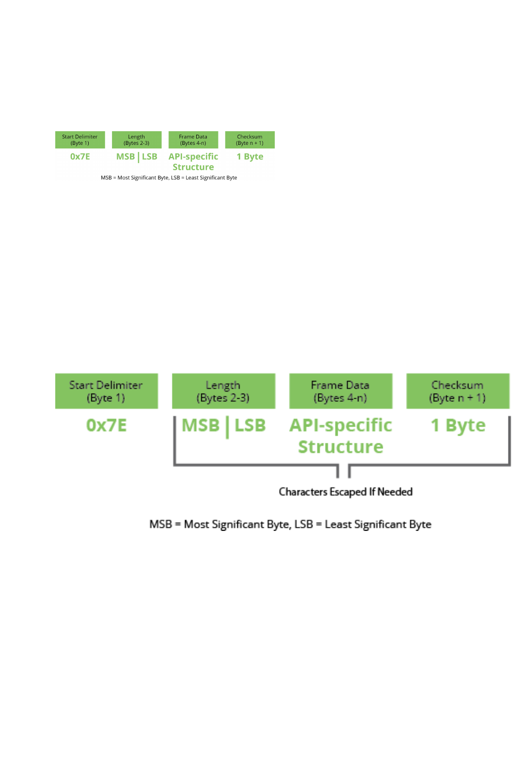
API mode overview
XBee/XBee-PRO XTend Compatible (XTC) RF Module User Guide 90
The APIdata frame structure differs depending on what mode you choose.
API operation (AP parameter = 1)
When you enable this mode, the following diagram illustrates the data frame structure:
The firmware silently discards any data it receives prior to the start delimiter. If the device does not
receive the frame correctly or if the checksum fails, the device discards the frame.
API operation-with escaped characters (AP parameter = 2)
API mode 2 is rarely necessary to use. API mode 1 is fully capable of transmitting all characters including
those that can be escaped. If you think you need to use API mode 2, contact Digi Support so we can
discuss your application. For details, read the following article:
http://knowledge.digi.com/articles/Knowledge_Base_Article/Escaped-Characters-and-API-Mode-2
When you enable this mode, the following diagram illustrates the data frame structure:
The following paragraphs explain what the fields within the API frame mean.
Start delimiter
The first byte of a frame consists of a special sequence of bits that indicate the beginning of a data frame.
Its value is always 0x7E. This allows an application to easily detect a new incoming frame.
Length
The length field specifies the total number of bytes included in the frame's data field. Its two-byte value
excludes the start delimiter, the length, and the checksum.
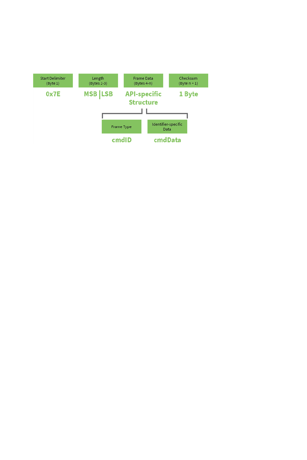
API mode overview
XBee/XBee-PRO XTend Compatible (XTC) RF Module User Guide 91
Frame data
This field contains the information that a device receives or will transmit. The structure of frame data
depends on the purpose of the API frame:
lFrame type is the API frame type identifier. It determines the type of API frame and
indicates how the Data field organizes the information.
lData contains the data itself. This information and its order depend on the what type of
frame that the Frame type field defines.
The Frame Type byte indicates which API messages the data bytes (Identifier-specific data) will contain.
Checksum
The value 0xFF minus the 8-bit sum of bytes from offset 3 to this byte. Checksum is the last byte of the
frame and helps test data integrity.
The device does not process frames sent through the serial interface with incorrect checksums, and
ignores their data.
Calculate and verify checksums
To calculate the checksum of an API frame:
1. Add all bytes of the packet, excluding the start delimiter 0x7E and the length (the second
and third bytes).
2. Keep only the lowest 8 bits from the result.
3. Subtract this quantity from 0xFF.
To verify the checksum of an API frame:
1. Add all bytes including the checksum; do not include the delimiter and length.
2. If the checksum is correct, the last two digits on the far right of the sum will equal 0xFF.

API mode overview
XBee/XBee-PRO XTend Compatible (XTC) RF Module User Guide 92
Escaped characters in API frames
If operating in API mode with escaped characters (AP parameter = 2), when you send or receive an API
frame, you must escape (flag) specific data values so they do not interfere with data frame sequencing. In
API operating mode with escaped characters, you must escape the following data bytes:
l0x7E: start delimiter
l0x7D: escape character
l0x11: XON
l0x13: XOFF
API operating mode with escaped characters guarantees that all the 0x7E bytes a device receives are
start delimiters: this character cannot be part of any of the other frame fields (length, data, or checksum)
since you must escape it.
To escape a character:
1. Insert 0x7D, the escape character.
2. Append it with the byte you want to escape, XORed with 0x20.
In API operating mode with escaped characters, the length field does not include any escape characters in
the frame and the firmware calculates the checksum with non-escaped data.
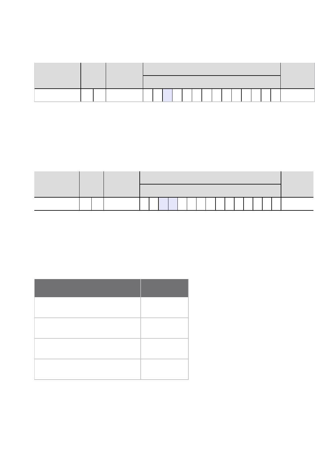
XTC RF ModuleAPI frame overview
XBee/XBee-PRO XTend Compatible (XTC) RF Module User Guide 93
Example: escape an API frame
To express the following API non-escaped frame in API operating mode with escaped characters:
Start delimiter Length Frame type Frame Data Checksum
Data
7E 00 0F 17 01 00 13 A2 00 40 AD 14 2E FF FE 02 4E 49 6D
You must escape the 0x13 byte:
1. Insert a 0x7D.
2. XOR byte 0x13 with 0x20: 13 ⊕20= 33
The following figure shows the resulting frame. Note that the length and checksum are the same as the
non-escaped frame.
Start delimiter Length Frame type Frame Data Checksum
Data
7E 00 0F 17 01 00 7D 33 A2 00 40 AD 14 2E FF FE 02 4E 49 6D
The length field has a two-byte value that specifies the number of bytes in the frame data field. It does not
include the checksum field.
XTC RF ModuleAPI frame overview
The device sends multi-byte values in big-endian format. The devices support the following API frames:
API frame name API ID
Transmit Request 0x01
RF Module Status 0x8A
Transmit Status 0x89
Receive Packet 0x81
RF Module Status 0x8A
Description
Devices send the status messages in this frame in response to specific conditions.

XTC RF ModuleAPI frame overview
XBee/XBee-PRO XTend Compatible (XTC) RF Module User Guide 94
Format
The following table provides the contents of the frame. For details on frame structure, see API frame
specifications on page 89.
Frame fields Byte(s) Description
Frame type 4 0x8A
Status 5 0x00 = Hardware reset
0x01 = Watchdog timer reset
Example
When a device powers up, it returns the following API frame:
Frame fields Offset Example
Start Delimiter 0 0x7E
Length MSB 1 0x00
LSB 2 0x02
Frame Type 3 0x8A
Status 4 0x00
Checksum 5 0x75
Transmit Request: 16-bit address 0x01
Description
This frame causes the device to send data as an RF packet to a specific destination.
Format
The following table provides the contents of the frame. For details on frame structure, see API frame
specifications on page 89.

XTC RF ModuleAPI frame overview
XBee/XBee-PRO XTend Compatible (XTC) RF Module User Guide 95
Frame fields Byte(s) Description
Frame type 4 0x01
Frame ID 5 Identifies the data frame for the host to correlate with a subsequent ACK.
Setting Frame ID to 0 disables the response frame.
Destination
address
6-7 MSB first, LSB last.
Broadcast = 0xFFFF.
Options 8 0 = standard.
1 = disable ACK.
RF data 9-n Up to 2048 bytes per packet. The payload size is limited by the PK
command.
Example
The following example shows how to send a transmission to a device with destination address 0x5642,
and payload “TxData0A”.
Frame fields Offset Example
Start delimiter 0 0x7E
Length MSB 1 0x00
LSB 2 0x0D
Frame type 3 0x01
Frame ID 4 0x01
Destination address MSB 5 0x56
LSB 6 0x42
Options 7 0x00

XTC RF ModuleAPI frame overview
XBee/XBee-PRO XTend Compatible (XTC) RF Module User Guide 96
Frame fields Offset Example
RF data 8 0x54
9 0x78
10 0x44
11 0x61
12 0x74
13 0x61
14 0x30
15 0x41
Checksum 16 0xAE
Transmit Status frame 0x89
Description
When a TX Request is completed, the device sends a TX Status message. This message will indicate if the
packet was transmitted successfully or if there was a failure.
Format
The following table provides the contents of the frame. For details on frame structure, see API frame
specifications on page 89.
Frame
fields
Byte
(s)
Description
Frame
type
4 0x89

XTC RF ModuleAPI frame overview
XBee/XBee-PRO XTend Compatible (XTC) RF Module User Guide 97
Frame
fields
Byte
(s)
Description
Frame
ID
5 Identifies the data frame for the host to correlate with a subsequent ACK. Setting
Frame ID to 0 disables the response frame.
Status 6 0 = success.
1 = all retries expired and no ACK received.
3 = a packet is purged due to a Polled Remote not receiving a poll.
Example
In the following example, the destination device reports that a unicast data transmission was successful
using a frame ID of 0x47.
Frame fields Offset Example
Start Delimiter 0 0x7E
Length MSB 1 0x00
LSB 2 0x03
Frame type 3 0x89
Frame ID 4 0x47
Options 5 0x00
Checksum 6 0x2F
Receive Packet: 16-bit address 0x81
Description
When the device receives an RF packet, it is sent out the UART using this message type.

XTC RF ModuleAPI frame overview
XBee/XBee-PRO XTend Compatible (XTC) RF Module User Guide 98
Format
The following table provides the contents of the frame. For details on frame structure, see API frame
specifications on page 89.
Frame
fields
Byte
(s)
Description
Frame
type
4 0x81
Source
address
5-6 MSB first
LSB last
RSSI 7 RSSI = hexadecimal equivalent of -dBm value. For example, if RX signal strength =
-40 dBm, it returns 0x28 (40 decimal).
Options 8 Bit 0 = ACK
Bit 1 = indicate broadcast
bits 2-7 = reserved
RF data 9-n Up to 2048 bytes per packet.
Example
In the following example, a device with a source address of 0xA35E sent a unicast data transmission to a
remote device with a payload of "RxData". The receiving device would send the following frame out its
UART:
Frame fields Offset Example
Start Delimiter 0 0x7E
Length MSB 1 0x00
LSB 2 0x0B
Frame type 3 0x81

XTC RF ModuleAPI frame overview
XBee/XBee-PRO XTend Compatible (XTC) RF Module User Guide 99
Frame fields Offset Example
Source address MSB 4 0xA3
LSB5 0x5E
RSSI 6 0x5D
Options 7 0x01
RF data 8 0x52
9 0x78
10 0x44
11 0x61
12 0x74
13 0x61
Checksum 14 0xDB

XBee/XBee-PRO XTend Compatible (XTC) RF Module User Guide 100
Network configurations
network topologies
The XTC RF Module supports three different network topologies: point-to-point, point-to-multipoint and
peer-to-peer.
Point-to-point networks
This following section provides the RF communication type and RF mode for XTC RF Module point-to-point
networks.
Definition
Point-to-point means an RF data link between two devices.
Sample network profile (Broadcast communications)
Use the default values for all devices.
Sample network profile (Acknowledged communications)
Note Assume the default value for all parameters that are not in this list. These profiles do not reflect
addressing implementations.
1. Use XCTU or another terminal program to send the AM command. See AM (Auto-set MY) on
page 58 for details.
2. Set the destination address to 0xFFFF, send: ATDT FFFF
Basic RF modes
Streaming, Multi-Transmit, Repeater.
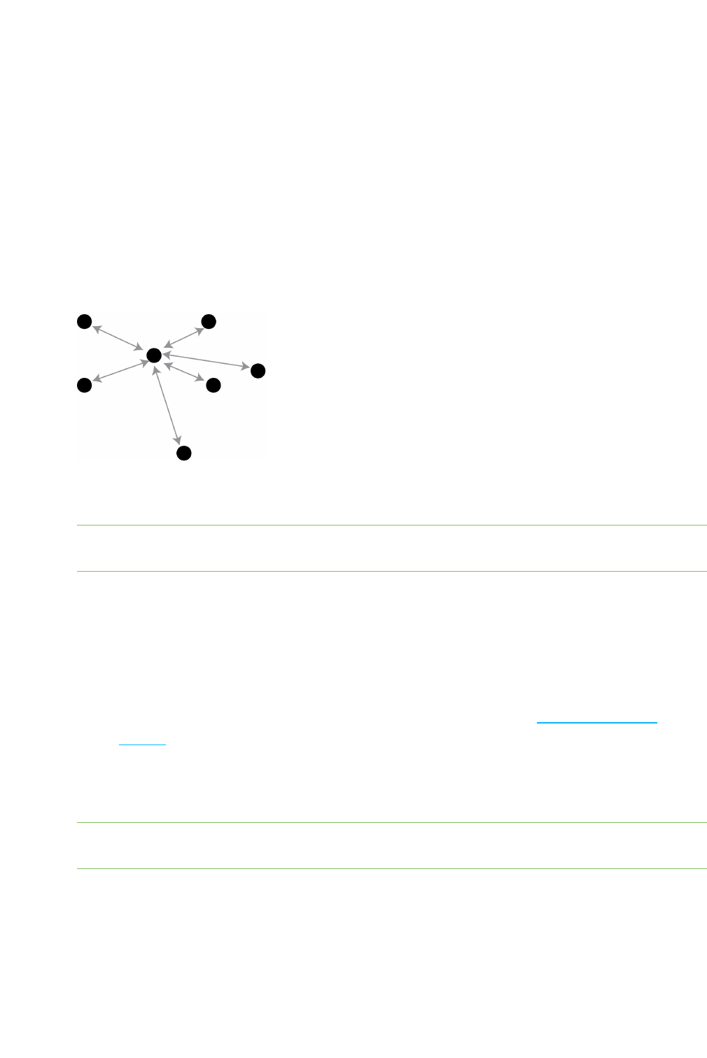
network topologies
XBee/XBee-PRO XTend Compatible (XTC) RF Module User Guide 101
Acknowledged RF mode
Acknowledged mode.
Point-to-multipoint networks
This following section provides the RF communication type and RF mode for XTC RF Module point-to-
multipoint networks.
Definition
Point-to-multipoint means a network with RF data links between one base and multiple remotes.
Sample network profile (Broadcast communications)
Note Assume the default value for all parameters that are not in this list. These profiles do not reflect
addressing implementations.
Base:
1. Send ATMY 0 to set the source address to 0x00.
2. Send ATDT FFFF to set the destination address to 0xFFFF.
Remotes:
1. Use XCTU or another terminal program to send the AM command. See AM (Auto-set MY) on
page 58 for details.
2. Send ATDT 0 to set the destination address to 0x00.
Sample network profile (Acknowledged communications)
Note Assume the default value for all parameters that are not in this list. These profiles do not reflect
addressing implementations.
Base:
1. Send ATMY 0 to set the source address to 0x00.
2. Send ATDT FFFF to set the destination address to 0xFFFF.

network topologies
XBee/XBee-PRO XTend Compatible (XTC) RF Module User Guide 102
3. Send ATRR 3 to set the number of retries to 3.
Remotes:
1. Use XCTU or another terminal program to send the AM command.
2. Send ATDT FFFF to set the destination address to 0xFFFF.
3. Send ATRR 3 to set the number of retries to 3.
Basic RF modes
Streaming, Multi-Transmit, Repeater, and Polling.
Acknowledged RF mode
Acknowledged and Polling.
Peer to peer networks
This following section provides the RF communication type and RF mode for XTC RF Module peer-to-peer
networks.
Definition
In Peer-to-peer networks, RF devices remain synchronized without the use of master/server
dependencies. Each device shares the roles of master and slave. Digi's peer-to-peer architecture features
fast synch times (35 ms to synchronize devices) and fast cold start times (50 ms before transmission).
Sample network profile (Broadcast communications)
Note Assume the default value for all parameters that are not in this list. These profiles do not reflect
addressing implementations.
Use the default values for all devices.
Sample network profile (Acknowledged communications)
Note Assume the default value for all parameters that are not in this list. These profiles do not reflect
addressing implementations.
All devices:
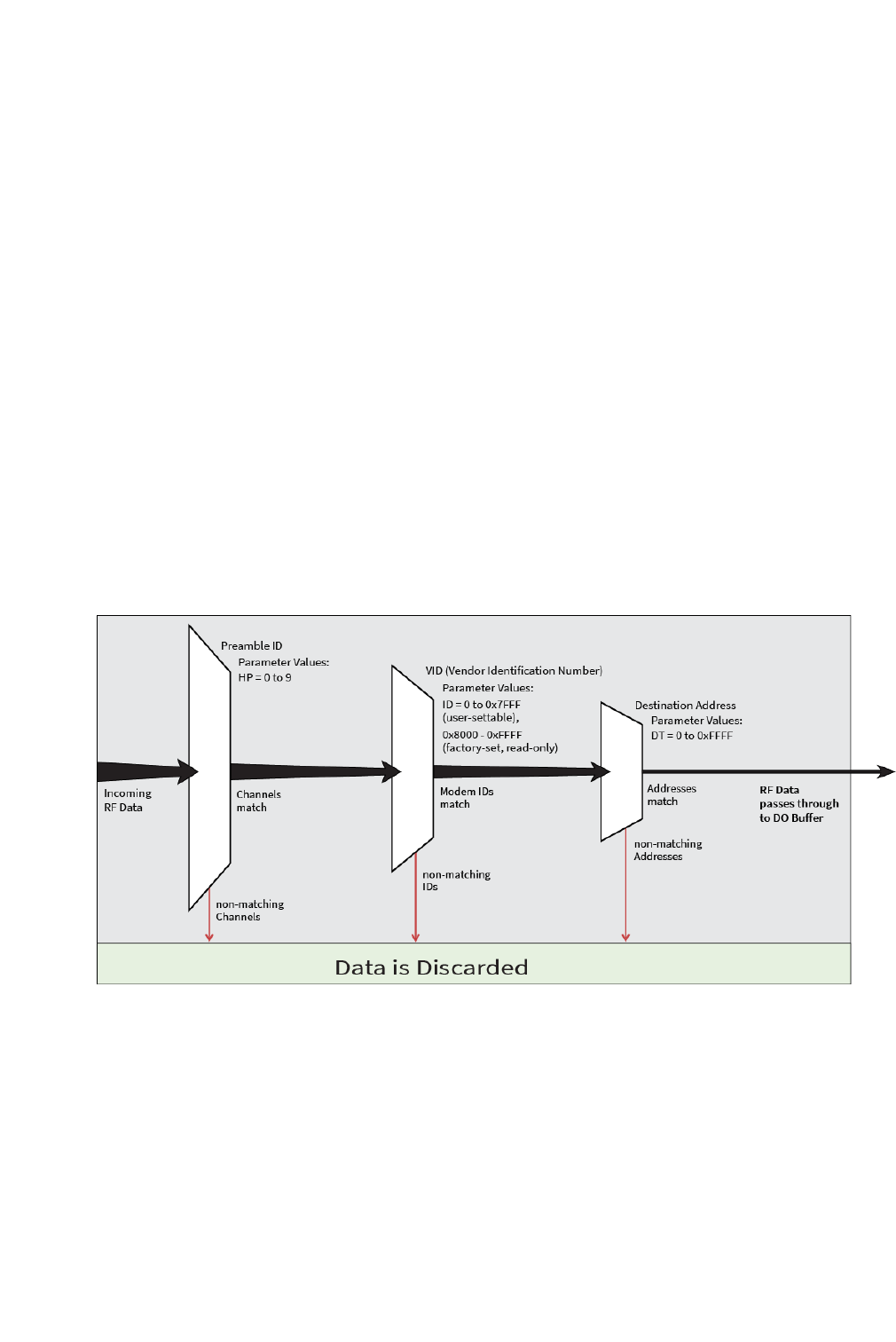
Addressing
XBee/XBee-PRO XTend Compatible (XTC) RF Module User Guide 103
1. Send ATMY 0 to set the source address to 0x00.
2. Send ATDT FFFF to set the destination address to 0xFFFF.
3. Send ATRR 3 to set the number of retries to 3.
Basic RF modes
Streaming.
Acknowledged RF mode
Acknowledged.
Addressing
Each RF packet contains addressing information that the receiving devices use to filter incoming RF data.
Receiving devices inspect the Preamble ID (HP parameter), Vendor Identification Number (ID parameter)
and Destination Address (DT parameter) in each RF packet. A receiving device discards all data that does
not pass through all three network security layers.
The following image illustrates the addressing layers in the RF packet header.
Address recognition
The transmitting device can address transmissions to a specific device or group of devices using the DT
and MK commands. A receiving device only accepts a packet if it determines that the packet is addressed
to it, either as a global or local packet. The receiving device makes this determination by inspecting the
destination address of the packet and comparing it to its own address and address mask.

Basic communications
XBee/XBee-PRO XTend Compatible (XTC) RF Module User Guide 104
The transmitting device determines whether the packet is for a specific node (local address) or multiple
nodes (global address) by comparing the packet's destination address (DT) and its own address mask
(MK). This assumes you program the address masks on the transmitting device and receiving device to the
same value for proper operation in each RF communication mode.
For more information, see DT (Destination Address) on page 59 and MK (Address Mask) on page 61.
Basic communications
Basic communications includes two sub-types:
lBroadcast. By default, the XTC RF Module communicates through Broadcast
communications and within a peer-to-peer network topology. When any device transmits,
all other devices within range receive the data and pass it directly to their host device.
lAddressed. If addressing parameters match, the device forwards the RF data it receives to
the DOUT buffer; otherwise, it discards the RF data.
When using Basic communications, the integrator handles any functions, such as acknowledgments, at the
application layer. The Broadcast modes provide transparent communications, meaning that the RF link
replaces a wired link.
Streaming mode (default)
Streaming mode is most appropriate for data systems that are more sensitive to latency and/or jitter
than to occasional packet loss; for example: streaming audio or video.
Characteristics Highest data throughput
Lowest latency and jitter
Reduced immunity to interference
Transmissions never acknowledged (ACK) by receiving device
(s)
Required parameter values (TX
device)
RR = 0
Related commands Networking (DT, MK, MY), Serial interfacing (PK, RB, RO, TT)
Streaming mode connection sequence
Events and processes in this mode are common to all of the other RF modes.
When streaming data, the firmware only observes the RB and RO parameters on the first packet.

Basic communications
XBee/XBee-PRO XTend Compatible (XTC) RF Module User Guide 105
After transmission begins, the transmission event continues without interruption until the DIN buffer is
empty or the device reaches the streaming limit (TT parameter). As with the first packet, the payload of
each subsequent packet includes up to the maximum packet size (PK parameter).
The TX (transmitting) device specifies the TT parameter as the maximum number of bytes the TX device
can send in one transmission event. After the device reaches the TT parameter threshold, the TX device
forces a random delay of 1 to RN delay slots; exactly 1 delay slot if RN = 0.
The TX device sends subsequent packets without an RF initializer since RX (receiving) devices remain
synchronized with the TX device for the duration of the transmission (from preceding packet information).
However, due to interference, some RX devices may lose data (and synchronization to the TX device),
particularly during long transmission events.
Once the TX device has sent all pending data or has reached the TT limit, the transmission event ends. The
TX device does not transmit again for exactly RN delay slots if the local (for example the TX device's) RN
parameter is set to a nonzero value. The RX device(s) do not transmit for a random number of delay slots
between 0 and (RN-1) if the local (for example the RX device's) RN parameter is set to a non-zero value.
These delays lessen congestion following long bursts of packets from a single TX device, during which
several RX devices may have become ready to transmit.
Multi-transmit mode
Use Multi-transmit mode for applications that require reliable delivery without using retries and
acknowledgments.
Characteristics Reliable delivery through forcing the transmission of every RF packet.
Every RF packet is sent exactly MT + 1 times, with no delays between
packets.
Diminished throughput and increased latency.
Required parameter values
(TX device)
MT ≥ 1.
Related commands Networking (DT, MK, MY, RN, TT), Serial interfacing (BR, PK, RB, RO),
RF interfacing (FS).
Multi-transmit mode connection sequence
In Multi-transmit mode, the device re-transmits each packet MT times, for a total of (MT+1) transmissions.
There is no delay between retransmissions, and the TX (transmitting) device never receives RF data
between retransmissions. Each retransmission includes an RF initializer. A transmission event may include

Basic communications
XBee/XBee-PRO XTend Compatible (XTC) RF Module User Guide 106
follow-on packets, each of which retransmit MT times. Devices ignore the Forced Sync (FS) parameter in
Multi-Transmit Mode.
The firmware does not apply the RB and RO parameters to follow-on packets, meaning that once
transmission has begun, it continues without interruption until the DIN buffer is empty or the device
reaches the streaming limit (TT parameter). As with the first packet, the payload of each follow-on packet
includes up to the maximum packet size (PK parameter) bytes, and the TX device checks for more pending
data near the end of each packet. The device does not send follow-on packets until it finishes all
retransmissions of the previous packet.
The TX device specifies the streaming limit (TT) as the maximum number of bytes that the TX device can
send in one transmission event, which may consist of many packets. If the device reaches the TT
parameter limit, the TX device forces a random delay of 1 to RN delay slots (exactly 1 delay slot if RN is
zero). In Multi-transmit mode, the firmware counts each packet only once when tracking the streaming
limit (TT), no matter how many times it is retransmitted.
When an RX (receiving) device receives a Multi-transmit packet, it calculates the amount of time remaining
in the Multi-transmit event, and inhibits its own transmissions for the duration of the Multi-transmit event,
plus a random number of delay slots between 0 and (RN-1). If the local RN parameter is zero, the delay is
only for the calculated duration of the event. An RX device only needs to receive one of the transmissions,
and it keep the channel off until the TX device is complete. If follow-on packets are coming, the RX devices
move to the new frequency and listen for the follow-on packet for a specific period of time.
Repeater mode
Use Repeater mode in networks where you need intermediary devices to relay data to devices beyond the
transmission range of the base device.

Basic communications
XBee/XBee-PRO XTend Compatible (XTC) RF Module User Guide 107
Characteristics Low power consumption.
Minimizes interference
Tags each RF packet with a unique Packet ID (PID).
Each repeater only repeats a packet once (the PID tracks the packet).
Increases latency and decreases throughput. The number of hops determine latency
and throughput, not the number of repeaters. Multiple repeaters within range of a
source node count as one hop.
All RF packets propagate to every device in the network (filtering rules apply).
Packet destination addresses (DT) determine which packets the device sends out
the serial port and/or retransmits.
Broadcast communications: each packet comes out every node exactly once.
Addressed communications: all devices see every packet. Only the devices with a
matching address forward it to the DOUT buffer.
Constraints Requires that each device have a unique MY parameter.
System must introduce only one packet at a time to the network for transmission.
The PK parameter determines the maximum number of bytes.
Each hop (H) decreases network throughput by a factor of 1/(H+1). Additional
repeaters add network redundancy without decreasing throughput.
Suggestions Insert a variable delay before repeating packets to avoid collisions (based on RSSI).
Buffer any incoming serial data and delay response packet transmissions until the
previous packet clears out of the network.
For best results, use the RO and RB commands to ensure that the RF packets align
with the underlying protocol packets as the network can only accept one RF packet
at a time.
Required
parameter
values (TX
device)
MD = 5 or 6.
MY = unique value. You can accomplish this by issuing the AM and WR commands to
all devices in the network.
Related
commands
Networking (MD, DT, MY, AM), Serial interfacing (RN, PK, RO, RB)
Repeater mode theory of operation
You can extend the effective range and reliability of your data system by forwarding traffic through one or
more repeaters. Instead of using routing tables and path discovery to establish dynamic paths through a

Basic communications
XBee/XBee-PRO XTend Compatible (XTC) RF Module User Guide 108
network, the repeater system uses a sophisticated algorithm to propagate each RF packet through the
entire network.
The network supports RF packets up to 2048 bytes when the RF data rate is set at 9600 bps (BR = 0). The
repeater network can operate using broadcast or addressed communications for multi-drop networks,
and it works well in many systems with no special configuration.
When in Repeater mode, the network repeats each message among all available devices exactly one time.
This mechanism eliminates the need for configuring specific routes. The following figure illustrates the
Repeater network topology.
Configure a repeater network
If an RF link is weak, a device is out-of-range or a difficult RF environment is present; you can use
repeaters to extend the effective range and reliability of the network.
A network may consist of End Nodes (EN), End/Repeater Nodes (ERN) and a Base Node (BN). The base
node initiates all communications. Both Repeater Nodes and End Nodes can source data, allowing
connection to host devices. Repeater Nodes however, are able to repeat information in a simple store and
forward fashion. As an example, one End Node (which can be a base or remote) must send a message to
another End Node. Because the End Node is out of range of the base device, you can use a repeater to
forward information from the Base to the End Node.
You can configure a repeater network to operate using Basic Broadcast or Basic Addressed
communications. The addressing capabilities of the device allow integrators to send a packet as a global
packet (DT = 0xFFFF) and shift out of every device in the network (Basic Broadcast). Alternately, you can
send the packet with a specific DT parameter so that only a specific remote node accepts it (Basic
Addressed).
Repeater network: configure communications
To configure a Repeater network for Basic broadcast communications:
1. Assign each device a unique MY (source) address. Use the AM command to configure a
unique source address based on the device serial number. This is essential because a
unique packet ID on each RF packet is based on the originator’s MY value.
2. Set DT = 0xFFFF to enable Basic Broadcast communications OR Basic Addressed
communications (DT specifies a specific destination).

Basic communications
XBee/XBee-PRO XTend Compatible (XTC) RF Module User Guide 109
3. Configure PK, RO and RB to ensure that the RF packet aligns with the protocol packet. For
example:
PK=0x100
RB=0x100
RO depends on baud rate
4. Set MD = 5 to configure one or more devices that you do not intend to be repeaters as
repeater End Nodes in the system.
5. Set MD = 6 to configure remote nodes as destinations. This ensures that the remote node
waits for the repeater traffic to subside before it transmits a response.
To configure a Repeater network for Basic addressed communications, use DT to assign unique
addresses to each device in the network.
AT commands to configure Repeater network functions
The following table lists the AT commands you use to configure repeater functions.
AT
Command
Binary
Command
AT Command
Name
Range # Bytes
Returned
Factory
Default
AM 0x3A (58d) Auto-set MY - - -
DT 0x00 (0d) Destination
Address
0 - 0xFFFF 2 0
MD 0x3C (60d) RF Mode 0 - 6 1 0
MY 0x2A (42d) Source Address 0 - 0xFFFF 2 0xFFFF
RN 0x19 (25d) Delay Slots 0 - 0xFF
[slots]
1 0
WR 0x08 (8d) Write - - -
Repeater network algorithm details
The firmware uses an algorithm to propagate each RF packet through the entire repeater network. Within
a repeater network, the firmware only defines Repeater Nodes and repeater End Nodes. Repeater Nodes
forward messages on to other devices within range; End Nodes do not.

Basic communications
XBee/XBee-PRO XTend Compatible (XTC) RF Module User Guide 110
The algorithm maintains a list of messages previously received in a buffer. The firmware discards
messages already in the buffer. This eliminates End Nodes receiving multiple copies of a packet from more
than one source, and also eliminates multiple repeaters within range of each other from continually
passing messages in an infinite loop.
Packet ID (PID) is composed of the TX (transmitting) device MY address and the packet sequence number.
The firmware ignores incoming packets with a PID already in the buffer.
Each device maintains a PID buffer 4-deep of previously received packets (managed as FIFO).
The firmware may shift packets out the serial port and/or repeat them depending on the DT parameter in
the RF packet. The following table shows the basis for these decisions.
Address Match Send out serial port? Repeat?
Global Yes Yes
Local Yes No
None No Yes
Repeat delay based on RSSI
A transmitted packet may be received by more that one repeater at the same time. In order to reduce the
probability that the repeaters will transmit at the same instant, resulting in a collision and possible data
loss; the firmware uses an algorithm that allows a variable back-off prior to a repeater retransmitting the
packet. The algorithm allows devices that receive the packet with a stronger RF signal (RSSI) to have the
first opportunity to retransmit the packet.
Use the RN (Delay Slots) parameter to configure this delay. Set RN = 0 (no delays) for small networks with
few repeaters or repeaters that are not within range of each other. Set RN = 1 for systems with two to
five repeaters that may be within range of each other.
The actual length of the delay is computed by the formula:
Delay (ms) = L * DS
DS = (-41-RSSI)/10*RN)+RandomInt(0,RN)
Where L is the length of the transmitted packet in milliseconds, DS is the number of delay slots to wait,
RSSI is the received signal strength in dBm, RN is the value of the RN register and RandomInt (A,B) is a
function that returns a random integer from A to B-0

Basic communications
XBee/XBee-PRO XTend Compatible (XTC) RF Module User Guide 111
Response packet delay
As a packet propagates through the repeater network, if any node receives the data and generates a
quick response, the network needs to delay the response so as not to collide with subsequent
retransmissions of the original packet. To reduce collisions, both repeater and end node devices in a
repeater network delay transmission of data shifted in the serial port to allow any repeaters within range
to complete their retransmissions.
The time for this delay is computed by the formula:
Maximum Delay (ms) = L * DS
DS = ((-41-(-100))/10)*RN)+RN+1
Where L is the length of the transmitted packet in milliseconds, DS is the number of delay slots to wait,
RSSI is the received signal strength in dBm, and RN is the value of the RN register.
Bandwidth considerations
Using broadcast repeaters in a network reduces the overall network data throughput as each repeater
must buffer an entire packet before retransmitting it. For example: if the destination is within range of the
transmitter and the packet is 32-bytes long, the transmission takes 12 ms on a device operating at
115,200 baud. If the same packet must propagate through two repeaters, it takes 12 ms to arrive at the
first repeater, 12 ms to get to the second and a final 12 ms to reach the destination for a total of 36 ms.
Accounting for UART transfer times (~1ms/byte at 9600 baud), the time for a server to send a 32-byte
query and receive a 32-byte response is about 200 ms, allowing for 5 polls per second. With the two
repeaters in the path, the same query/response sequence would take about 500 ms for two polls per
second.
Generally, network throughput decreases by a factor of 1/(R+1), with R representing the number of
repeaters between the source and destination.
Polling mode (basic)
Polling mode (basic) and Polling mode (acknowledged) operate in the same way. The only difference
between the two modes is in their means of achieving reliable delivery of data. Polling mode (basic) uses
multiple transmissions to achieve reliable delivery.

Basic communications
XBee/XBee-PRO XTend Compatible (XTC) RF Module User Guide 112
Characteristics Uses a high percentage of available network bandwidth.
Eliminates collisions.
Works with reliable delivery (RR or MT parameters).
Supports binary data transfers.
Base device requests packets from remote device by polling a sequential range of
addresses.
Base device is configured to specify the range of addresses being polled.
Uses inter-character delay to create RF packet lengths aligned with protocol packet
lengths up to 2048 bytes long.
Constraints The minimum time interval between polling cycles is configurable. However, if the
remote devices cannot all be processed within that time interval, the polling cycle is
ineffective (i.e. it will impose no additional delay). In order to ensure a pause
between polling cycles, you must set PD to a value that is large enough to
accommodate the pause.
Recommended
use
Use for point-to-multipoint applications that require Reliable Delivery of data. Use
this mode when it is critical that a base device be able to discern data coming from
multiple devices.
Required
parameter
values (Base)
MD (RF Mode) = 3
PB (Polling Begin Address)
PE (Polling End Address)
Required
parameter
values
(Remote)
MD (RF Mode) = 4
Related
commands
Networking: MT, PD, DT, MY, and AM
Polling mode theory of operation
A Polling Base device cycles through a sequential range of addresses. The Polling Base polls each Polling
Remote device, waits for a response, then poll the next remote address in the sequence. Each Polling
Remote responds by sending the data from its DIN buffer following the RB and RO parameters. When
there is no eligible data to send, the Polling Remote does not respond. The Polling Base polls the next
address in the polling sequence after a short delay.

Acknowledged communications: Acknowledged mode
XBee/XBee-PRO XTend Compatible (XTC) RF Module User Guide 113
Configure a Polling Base
To configure a device as a Polling Base:
1. Set MD = 3.
2. Set MY = 0.
3. Set the sequential range of polling addresses using PB and PE.
4. (Optional) Enable Basic Reliable Delivery (MT ≥ 0). The firmware also supports
Acknowledged Reliable Delivery. For more information, see Polling mode (acknowledged)
on page 115.
5. (Optional) Use PD to configure a delay between polls to slow down the system, if needed.
6. (Optional) Enable API Mode to address remote devices within polling range on a packet-by-
packet basis.
Configure a Polling Remote
To configure a device as a Polling Remote:
1. Set MD = 4.
2. Configure sequential source addresses for all remote devices using MY.
3. Set DT to point to the Polling Base (DT = 0x0000).
4. (Optional) Enable Basic Reliable Delivery (MT >= 0). The firmware also supports
Acknowledged Reliable Delivery. For more information, see Polling mode (acknowledged)
on page 115.
Acknowledged communications: Acknowledged mode
Use Acknowledged mode for applications that need reliable delivery. If messages are smaller than 256
bytes, use the RB and RO commands to align RF packets to application packets.
Characteristics Reliable delivery through positive acknowledgments for each packet.
Throughput, latency and jitter vary depending on the quality of the
channel and the strength of the signal.
Required parameter
values (TX device)
RR (Retries) >= 1
Related commands Networking (DT, MK, RR), Serial Interfacing (PK, RN, RO, RB, TT)

Acknowledged communications: Acknowledged mode
XBee/XBee-PRO XTend Compatible (XTC) RF Module User Guide 114
Acknowledged mode connection sequence
After sending a packet while in Acknowledged mode, the TX (transmitting) device listens for an
acknowledgment (ACK). If it receives the ACK, it either moves on to sending a subsequent packet if more
transmit data is pending or waits for exactly RN random delay slots before allowing another transmission
if no more data is pending transmit.
If the TX device does not receive the ACK within the allotted time, it retransmits the packet with a new RF
initializer following the ACK slot. There is no delay between the first ACK slot and the first retransmission.
Subsequent retransmissions incur a delay of a random number of delay slots, between 0 and RN. If RN is
set to 0 on the TX device, there are never any back-off delays between retransmissions. During back-off
delays, the TX device goes into Idle Mode and may receive RF data. This can have the effect of increasing
the back-off delay, as the device cannot return to Transmit (or retransmit) mode as long as it is receiving
RF data.
After receiving and acknowledging a packet, the RX (receiving) device moves to the next frequency and
listens for either a retransmission or new data for a specific period of time. Even if the TX device indicates
that it has no more pending transmit data, it may not have received the previous ACK, and so may
retransmit the packet, possibly with no delay after the ACK slot. In this case, the RX device always detects
the immediate retransmission, which holds off the communications channel and reduces collisions. RX
devices acknowledge each retransmission they receive, but they only pass the first copy of a packet they
receive out the UART.
The device does not apply the RB and RO parameters to subsequent packets, meaning that once
transmission begins, it continues uninterrupted until the DIN buffer is empty or it reaches the streaming
limit (TT parameter. As with the first packet, the payload of each subsequent packet includes up to the
maximum packet size (PK parameter), and the TX device checks for more pending data near the end of
each packet.
The TT parameter specifies the maximum number of bytes that the TX device sends in one transmission
event, which may consist of many packets and retries. If a device reaches the TT parameter limit, the TX
device forces a random delay of 1 to RN delay slots (exactly 1 delay slot if RN is zero). Each packet counts
only once toward TT, no matter how many times the packet is retransmitted.
Subsequent packets in Acknowledged mode are similar to those in Streaming mode, with the addition of
an ACK between each packet, and the possibility of retransmissions. The device sends subsequent packets
without an RF initializer, as the RX devices are already synchronized to the TX device from the preceding
packet(s) and they remain synchronized for the duration of the transmission event. Each packet
retransmission includes an RF initializer.
Once the TX device sends all pending data or reaches the TT limit, the acknowledged transmission event is
complete. The TX device does not transmit again for exactly RN delay slots, if the local RN parameter is set

Acknowledged communications: Acknowledged mode
XBee/XBee-PRO XTend Compatible (XTC) RF Module User Guide 115
to a non-zero value. The RX device does not transmit for a random number of delay slots between 0 and
(RN-1), if the local RN parameter is set to a non-zero value. The intent of these delays is to lessen
congestion following long bursts of packets from a single TX device, during which several RX devices may
have themselves become ready to transmit.
Polling mode (acknowledged)
Polling mode (acknowledged) and Polling mode (basic) operate in the same way. The difference between
the two modes is in their means of achieving the reliable delivery of data. In Polling mode (acknowledged),
the firmware achieves reliable delivery using retries and acknowledgments.
Characteristics Uses a high percentage of available network bandwidth.
Eliminates collisions.
Works with reliable delivery (RR or MT parameters).
Supports binary data transfers.
Base device requests packets from remote device by polling a sequential range of
addresses.
Base device is configured to specify the range of addresses being polled.
Uses inter-character delay to create RF packet lengths aligned with protocol packet
lengths up to 2048 bytes long.
Constraints The minimum time interval between polling cycles is configurable. However, if the
remote devices cannot all be processed within that time interval, the polling cycle is
ineffective (i.e. it will impose no additional delay). In order to ensure a pause
between polling cycles, PD must be set to a value which is large enough to
accommodate the pause.
Recommended
use
Use for point-to-multipoint applications that require Reliable Delivery of data. Use
this mode when it is critical that a base device be able to discern data coming from
multiple devices.
Required
parameter
values (Base)
MD (RF Mode) = 3,
PB (Polling Begin Address)
PE (Polling End Address)

Acknowledged communications: Acknowledged mode
XBee/XBee-PRO XTend Compatible (XTC) RF Module User Guide 116
Required
parameter
values
(Remote)
MD (RF Mode) = 4
Related
commands
Networking (RR, PD, DT, MY, AM)
For configuration and theory of operation information, see Polling mode theory of operation on page 112,
Configure a Polling Base on page 113 and Configure a Polling Remote on page 113.
XBee/XBee-PRO XTend Compatible (XTC) RF Module User Guide 117
Certifications
FCC (United States)
These RF modules comply with Part 15 of the FCC rules and regulations. Compliance with the labeling
requirements, FCC notices and antenna usage guidelines is required.
In order to operate under Digi’s FCC Certification, integrators must comply with the following regulations:
1. The integrator must ensure that the text provided with this device (in the labeling
requirements section that follows) is placed on the outside of the final product and within
the final product operation manual.
2. The device may only be used with antennas that have been tested and approved for use
with this device; refer to FCC antenna certifications on the next page.
OEM labeling requirements
The Original Equipment Manufacturer (OEM) must ensure that FCC labeling requirements
are met. This includes a clearly visible label on the outside of the final product enclosure that
displays the text shown in the figure below.
The following text is the required FCC label for OEM products containing the XBee-PRO SX RF Module:
Contains FCC ID: MCQ-XBPSX
The enclosed device complies with Part 15 of the FCC Rules. Operation is subject to the following two
conditions: (i.) this device may not cause harmful interference and (ii.) this device must accept any
interference received, including interference that may cause undesired operation.
The following text is the required FCC label for OEM products containing the XBee SX RF Module:

FCC (United States)
XBee/XBee-PRO XTend Compatible (XTC) RF Module User Guide 118
Contains FCC ID: MCQ-XBSX
The enclosed device complies with Part 15 of the FCC Rules. Operation is subject to the following two
conditions: (i.) this device may not cause harmful interference and (ii.) this device must accept any
interference received, including interference that may cause undesired operation.
FCC notices
IMPORTANT: These RF modules have been certified by the FCC for use with other products without any
further certification (as per FCC section 2.1091). Modifications not expressly approved by Digi could void
the user’s authority to operate the equipment.
IMPORTANT: Integrators must test final product to comply with unintentional radiators (FCC sections
15.107 & 15.109) before declaring compliance of their final product to Part 15 of the FCC rules.
IMPORTANT: These RF modules have been certified for remote and base radio applications. If the module
will be used for portable applications, the device must undergo SAR testing.
This equipment has been tested and found to comply with the limits for a Class B digital device, pursuant
to Part 15 of the FCC Rules. These limits are designed to provide reasonable protection against harmful
interference in a residential installation. This equipment generates, uses and can radiate radio frequency
energy and, if not installed and used in accordance with the instructions, may cause harmful interference
to radio communications. However, there is no guarantee that interference will not occur in a particular
installation.
If this equipment does cause harmful interference to radio or television reception, which can be
determined by turning the equipment off and on, the user is encouraged to try to correct the interference
by one or more of the following measures: Re-orient or relocate the receiving antenna, Increase the
separation between the equipment and receiver, Connect equipment and receiver to outlets on different
circuits, or Consult the dealer or an experienced radio/TV technician for help.
FCC antenna certifications
This device has been tested with the antennas listed in the tables of this section. When
integrated into products, fixed antennas require installation preventing end users from
replacing them with non-approved antennas. Antennas not listed in the tables must be
tested to comply with FCC Section 15.203 (unique antenna connectors) and Section 15.247
(emissions).
Fixed base station and mobile applications
Digi devices are pre-FCC approved for use in fixed base station and mobile applications. When the antenna
is mounted at least 20cm (8") from nearby persons, the application is considered a mobile application.

FCC (United States)
XBee/XBee-PRO XTend Compatible (XTC) RF Module User Guide 119
Portable applications and SAR testing
When the antenna is mounted closer than 20 cm to nearby persons, then the application is considered
"portable" and requires an additional test be performed on the final product. This test is called Specific
Absorption Rate (SAR) testing and measures the emissions from the device and how they affect the
person.
RF exposure statement
This statement must be included as a CAUTION statement in integrator product manuals.
WARNING: This equipment is approved only for mobile and base station transmitting devices.
Antenna(s) used for this transmitter must be installed to provide a separation distance of at
least 34 cm from all persons and must not be co-located or operating in conjunction with any
other antenna or transmitter.
XBee-PRO XTC Antenna options
The following tables cover the antennas that are approved for use with the XBee-PRO XTC RF modules. If
applicable, the tables show the required cable loss between the device and the antenna.
Digi does not carry all of these antenna variants. Contact Digi Sales for available antennas.
Dipole antennas
All antenna part numbers followed by an asterisk (*) are not available from Digi. Consult with an antenna
manufacturer for an equivalent option.
Part Number Type Connector Gain Required
Antenna
Cable Loss
Application
A09-HSM-7 Straight half-wave RPSMA 2.1
dBi
0.4 dB Fixed /
Mobile
A09-HASM-675 Articulated half-
wave
RPSMA 2.1
dBi
0.4 dB Fixed /
Mobile
A09-HABMM-P5I Swivel half wave
with 5" pigtail
MMCX 2.1
dBi
0.4 dB Fixed /
Mobile

FCC (United States)
XBee/XBee-PRO XTend Compatible (XTC) RF Module User Guide 120
Part Number Type Connector Gain Required
Antenna
Cable Loss
Application
A09-HBMM-P5I Straight half-wave
with 6" pigtail
MMCX 2.1
dBi
0.4 dB Fixed /
Mobile
A09-HASM-7 Articulated half-
wave
RPSMA 2.1
dBi
0.4 dB Fixed
A09-HRSM* Right angle half-
wave
RPSMA 2.1
dBi
0.4 dB Fixed
A09-HG* Glass mounted
half-wave
RPSMA 2.1
dBi
0.4 dB Fixed
A09-HATM* Articulated half-
wave
RPTNC 2.1
dBi
0.4 dB Fixed
A09-H* Half-wave dipole RPSMA 2.1
dBi
0.4 dB Fixed
Yagi antennas
All antenna part numbers followed by an asterisk (*) are not available from Digi. Consult with an antenna
manufacturer for an equivalent option.
Part
Number
Type Gain Connector Required
Antenna
Cable Loss
Application
A09-Y6NF* 2 element
Yagi
6.1 dBi N 2.0 dB Fixed/Mobile
A09-Y7NF* 3 element
Yagi
7.1 dBi N 3.0 dB Fixed/Mobile
A09-Y8NF 4 element
Yagi
8.1 dBi N 4.0 dB Fixed/Mobile

FCC (United States)
XBee/XBee-PRO XTend Compatible (XTC) RF Module User Guide 121
Part
Number
Type Gain Connector Required
Antenna
Cable Loss
Application
A09-Y9NF* 4 element
Yagi
9.1 dBi N 5.0 dB Fixed/Mobile
A09-
Y10NF*
5 element
Yagi
10.1 dBi N 6.0 dB Fixed/Mobile
A09-Y11NF 6 element
Yagi
11.1 dBi N 7.0 dB Fixed/Mobile
A09-
Y12NF*
7 element
Yagi
12.1 dBi N 8.0 dB Fixed/Mobile
A09-
Y13NF*
9 element
Yagi
13.1 dBi N 9.0 dB Fixed/Mobile
A09-
Y14NF*
14 element
Yagi
14.0 dBi N 9.9 dB Fixed/Mobile
A09-Y6TM* 2 element
Yagi
6.1 dBi RPTNC 2.0 dB Fixed/Mobile
A09-Y7TM* 3 element
Yagi
7.1 dBi RPTNC 3.0 dB Fixed/Mobile
A09-Y8TM* 4 element
Yagi
8.1 dBi RPTNC 4.0 dB Fixed/Mobile
A09-Y9TM* 4 element
Yagi
9.1 dBi RPTNC 5.0 dB Fixed/Mobile
A09-Y10TM-
P10I
5 element
Yagi
10.1 dBi RPTNC 6.0 dB Fixed/Mobile

FCC (United States)
XBee/XBee-PRO XTend Compatible (XTC) RF Module User Guide 122
Part
Number
Type Gain Connector Required
Antenna
Cable Loss
Application
A09-
Y11TM*
6 element
Yagi
11.1 dBi RPTNC 7.0 dB Fixed/Mobile
A09-
Y12TM*
7 element
Yagi
12.1 dBi RPTNC 8.0 dB Fixed/Mobile
A09-
Y13TM*
9 element
Yagi
13.1 dBi RPTNC 9.0 dB Fixed/Mobile
A09-
Y14TM*
14 element
Yagi
14.0 dBi RPTNC 9.9 dB Fixed/Mobile
Omni-directional base station antennas
All antenna part numbers followed by an asterisk (*) are not available from Digi. Consult with an antenna
manufacturer for an equivalent option.
Part
Number
Type Gain Connector Required Antenna Cable
Loss
Application
A09-F0NF* Fiberglass Base
Station
0 dBi N - Fixed
A09-F1NF* Fiberglass Base
Station
1.0
dBi
N - Fixed
A09-F2NF-
M
Fiberglass Base
Station
2.1
dBi
N - Fixed
A09-F3NF* Fiberglass Base
Station
3.1
dBi
N - Fixed
A09-F4NF* Fiberglass Base
Station
4.1
dBi
N - Fixed

FCC (United States)
XBee/XBee-PRO XTend Compatible (XTC) RF Module User Guide 123
Part
Number
Type Gain Connector Required Antenna Cable
Loss
Application
A09-F5NF-
M
Fiberglass Base
Station
5.1
dBi
N - Fixed
A09-F6NF* Fiberglass Base
Station
6.1
dBi
N 0.9 dB Fixed
A09-F7NF* Fiberglass Base
Station
7.1
dBi
N 1.9 dB Fixed
A09-F8NF-
M
Fiberglass Base
Station
8.1
dBi
N 2.9 dB Fixed
A09-F0SM* Fiberglass Base
Station
0 dBi RPSMA - Fixed
A09-F1SM* Fiberglass Base
Station
1.0
dBi
RPSMA - Fixed
A09-F2SM* Fiberglass Base
Station
2.1
dBi
RPSMA - Fixed
A09-F3SM* Fiberglass Base
Station
3.1
dBi
RPSMA - Fixed
A09-F4SM* Fiberglass Base
Station
4.1
dBi
RPSMA - Fixed
A09-F5SM* Fiberglass Base
Station
5.1
dBi
RPSMA - Fixed
A09-F6SM* Fiberglass Base
Station
6.1
dBi
RPSMA 0.9 dB Fixed

FCC (United States)
XBee/XBee-PRO XTend Compatible (XTC) RF Module User Guide 124
Part
Number
Type Gain Connector Required Antenna Cable
Loss
Application
A09-F7SM* Fiberglass Base
Station
7.1
dBi
RPSMA 1.9 dB Fixed
A09-F8SM* Fiberglass Base
Station
8.1
dBi
RPSMA 2.9 dB Fixed
A09-F0TM* Fiberglass Base
Station
0 dBi RPTNC - Fixed
A09-F1TM* Fiberglass Base
Station
1.0
dBi
RPTNC - Fixed
A09-F2TM* Fiberglass Base
Station
2.1
dBi
RPTNC - Fixed
A09-F3TM* Fiberglass Base
Station
3.1
dBi
RPTNC - Fixed
A09-F4TM* Fiberglass Base
Station
4.1
dBi
RPTNC - Fixed
A09-F5TM* Fiberglass Base
Station
5.1
dBi
RPTNC - Fixed
A09-F6TM* Fiberglass Base
Station
6.1
dBi
RPTNC 0.9 dB Fixed
A09-F7TM* Fiberglass Base
Station
7.1
dBi
RPTNC 1.9 dB Fixed
A09-F8TM* Fiberglass Base
Station
8.1
dBi
RPTNC 2.9 dB Fixed

FCC (United States)
XBee/XBee-PRO XTend Compatible (XTC) RF Module User Guide 125
Part
Number
Type Gain Connector Required Antenna Cable
Loss
Application
A09-W7* Wire Base Station 7.1
dBi
RPN 1.9 dB Fixed
A09-W7SM* Wire Base Station 7.1
dBi
RPSMA 1.9 dB Fixed
A09-W7TM* Wire Base Station 7.1
dBi
RPTNC 1.9 dB Fixed
Dome antennas
All antenna part numbers followed by an asterisk (*) are not available from Digi. Consult with an antenna
manufacturer for an equivalent option.
Part
Number
Type Gain Connector Required Antenna
Cable Loss
Application
A09-
D3PNF*
Omnidirectional
permanent mount
3.0
dBi
N 0.4 dB Fixed/Mobile
A09-
D3NF*
Omnidirectional magnetic
mount
3.0
dBi
N 0.4 dB Fixed/Mobile
A09-
D3PTM*
Omnidirectional
permanent mount
3.0
dBi
RPTNC 0.4 dB Fixed/Mobile
A09-
D3PSM*
Omnidirectional
permanent mount
3.0
dBi
RPSMA 0.4 dB Fixed/Mobile
Monopole antennas
All antenna part numbers followed by an asterisk (*) are not available from Digi. Consult with an antenna
manufacturer for an equivalent option.

FCC (United States)
XBee/XBee-PRO XTend Compatible (XTC) RF Module User Guide 126
Part
Number
Type Gain Connector Required Antenna
Cable Loss
Application
A09-QRAMM 3" Quarter wave wire 2.1
dBi
MMCX - Fixed/Mobile
A09-QRSM-
2.1*
Quarter wave 2.1" right
angle
3.3
dBi
RPSMA 0.4 dB Fixed/Mobile
A09-QW* Quarter wave wire 1.9
dBi
Permanent - Fixed/Mobile
A09-QSM-3* Quarter wave straight 1.9
dBi
RPSMA - Fixed/Mobile
A09-QSM-
3H*
Heavy duty quarter
wave straight
1.9
dBi
RPSMA - Fixed/Mobile
A09-QBMM-
P6I*
Quarter wave w/ 6"
pigtail
1.9
dBi
MMCX - Fixed/Mobile
A09-QHSM-
2*
2" straight 1.9
dBi
RPSMA - Fixed/Mobile
A09-QHRSM-
2*
2" right angle 1.9
dBi
RPSMA - Fixed/Mobile
A09-QHRSM-
170*
1.7" right angle 1.9
dBi
RPSMA - Fixed/Mobile
A09-QRSM-
380*
3.8" right angle 1.9
dBi
RPSMA - Fixed/Mobile
A09-QAPM-
520*
5.2" articulated screw
mount
1.9
dBi
Permanent - Fixed/Mobile

FCC (United States)
XBee/XBee-PRO XTend Compatible (XTC) RF Module User Guide 127
Part
Number
Type Gain Connector Required Antenna
Cable Loss
Application
A09-QSPM-
3*
3" straight screw
mount
1.9
dBi
Permanent - Fixed/Mobile
A09-QAPM-
3*
3" articulated screw
mount
1.9
dBi
Permanent - Fixed/Mobile
A09-QAPM-
3H*
3" articulated screw
mount
1.9
dBi
Permanent - Fixed/Mobile
XBee XTC antenna options
The following tables cover the antennas that are approved for use with the XBee XTC RF modules. If
applicable, the tables show the required cable loss between the device and the antenna.
Digi does not carry all of these antenna variants. Contact Digi Sales for available antennas.
Dipole antennas
All antenna part numbers followed by an asterisk (*) are not available from Digi. Consult with an antenna
manufacturer for an equivalent option.
Part Number Type Connector Gain Required
Antenna
Cable
Loss
Application
A09-HSM-7 Straight half-wave RPSMA 2.1
dBi
0.4 dB Fixed / Mobile
A09-HASM-675 Articulated half-
wave
RPSMA 2.1
dBi
0.4 dB Fixed / Mobile
A09-HABMM-P5I Swivel half wave
with 5" pigtail
MMCX 2.1
dBi
0.4 dB Fixed / Mobile
A09-HBMM-P5I Straight half-wave
with 6" pigtail
MMCX 2.1
dBi
0.4 dB Fixed / Mobile

FCC (United States)
XBee/XBee-PRO XTend Compatible (XTC) RF Module User Guide 128
Part Number Type Connector Gain Required
Antenna
Cable
Loss
Application
A09-HASM-7 Articulated half-
wave
RPSMA 2.1
dBi
0.4 dB Fixed
A09-HRSM* Right angle half-
wave
RPSMA 2.1
dBi
0.4 dB Fixed
A09-HG* Glass mounted
half-wave
RPSMA 2.1
dBi
0.4 dB Fixed
A09-HATM* Articulated half-
wave
RPTNC 2.1
dBi
0.4 dB Fixed
A09-H* Half-wave dipole RPSMA 2.1
dBi
0.4 dB Fixed
Yagi antennas
All antenna part numbers followed by an asterisk (*) are not available from Digi. Consult with an antenna
manufacturer for an equivalent option.
Part
Number
Type Gain Connector Required
Antenna
Cable Loss
Application
A09-Y6NF* 2 element
Yagi
6.1 dBi N - Fixed/Mobile
A09-Y7NF* 3 element
Yagi
7.1 dBi N - Fixed/Mobile
A09-Y8NF 4 element
Yagi
8.1 dBi N - Fixed/Mobile

FCC (United States)
XBee/XBee-PRO XTend Compatible (XTC) RF Module User Guide 129
Part
Number
Type Gain Connector Required
Antenna
Cable Loss
Application
A09-Y9NF* 4 element
Yagi
9.1 dBi N - Fixed/Mobile
A09-Y10NF* 5 element
Yagi
10.1 dBi N - Fixed/Mobile
A09-Y11NF 6 element
Yagi
11.1 dBi N - Fixed/Mobile
A09-Y12NF* 7 element
Yagi
12.1 dBi N - Fixed/Mobile
A09-Y13NF* 9 element
Yagi
13.1 dBi N - Fixed/Mobile
A09-Y14NF* 10 element
Yagi
14.1 dBi N - Fixed/Mobile
A09-Y14NF-
ALT*
12 element
Yagi
14.1 dBi N - Fixed/Mobile
A09-Y15NF 13 element
Yagi
15.1 dBi N 0.7 dB Fixed/Mobile
A09-Y15NF-
ALT*
15 element
Yagi
15.1 dBi N 0.7 dB Fixed/Mobile
A09-Y6TM* 2 element
Yagi
6.1 dBi RPTNC - Fixed/Mobile
A09-Y7TM* 3 element
Yagi
7.1 dBi RPTNC - Fixed/Mobile

FCC (United States)
XBee/XBee-PRO XTend Compatible (XTC) RF Module User Guide 130
Part
Number
Type Gain Connector Required
Antenna
Cable Loss
Application
A09-Y8TM* 4 element
Yagi
8.1 dBi RPTNC - Fixed/Mobile
A09-Y9TM* 4 element
Yagi
9.1 dBi RPTNC - Fixed/Mobile
A09-Y10TM-
P10*
5 element
Yagi
10.1 dBi RPTNC - Fixed/Mobile
A09-
Y11TM*
6 element
Yagi
11.1 dBi RPTNC - Fixed/Mobile
A09-
Y12TM*
7 element
Yagi
12.1 dBi RPTNC - Fixed/Mobile
A09-
Y13TM*
9 element
Yagi
13.1 dBi RPTNC - Fixed/Mobile
A09-
Y14TM*
10 element
Yagi
14.1 dBi RPTNC - Fixed/Mobile
A09-Y14TM-
ALT*
12 element
Yagi
14.1 dBi RPTNC - Fixed/Mobile
A09-
Y15TM*
13 element
Yagi
15.1 dBi RPTNC 0.7 dB Fixed/Mobile
A09-Y15TM-
P10I
15 element
Yagi
15.1 dBi RPTNC 0.7 dB Fixed/Mobile
Omni-directional base station antennas
All antenna part numbers followed by an asterisk (*) are not available from Digi. Consult with an antenna
manufacturer for an equivalent option.

FCC (United States)
XBee/XBee-PRO XTend Compatible (XTC) RF Module User Guide 131
Part
Number
Type Gain Connector Required Antenna Cable
Loss
Application
A09-F0NF* Fiberglass Base
Station
0 dBi N - Fixed
A09-F1NF* Fiberglass Base
Station
1.0
dBi
N - Fixed
A09-F2NF-
M
Fiberglass Base
Station
2.1
dBi
N - Fixed
A09-F3NF* Fiberglass Base
Station
3.1
dBi
N - Fixed
A09-F4NF* Fiberglass Base
Station
4.1
dBi
N - Fixed
A09-F5NF-
M
Fiberglass Base
Station
5.1
dBi
N - Fixed
A09-F6NF* Fiberglass Base
Station
6.1
dBi
N - Fixed
A09-F7NF* Fiberglass Base
Station
7.1
dBi
N - Fixed
A09-F8NF-
M
Fiberglass Base
Station
8.1
dBi
N 0.7 dB Fixed
A09-F0SM* Fiberglass Base
Station
0 dBi RPSMA - Fixed
A09-F1SM* Fiberglass Base
Station
1.0
dBi
RPSMA - Fixed

FCC (United States)
XBee/XBee-PRO XTend Compatible (XTC) RF Module User Guide 132
Part
Number
Type Gain Connector Required Antenna Cable
Loss
Application
A09-F2SM* Fiberglass Base
Station
2.1
dBi
RPSMA - Fixed
A09-F3SM* Fiberglass Base
Station
3.1
dBi
RPSMA - Fixed
A09-F4SM* Fiberglass Base
Station
4.1
dBi
RPSMA - Fixed
A09-F5SM* Fiberglass Base
Station
5.1
dBi
RPSMA - Fixed
A09-F6SM* Fiberglass Base
Station
6.1
dBi
RPSMA - Fixed
A09-F7SM* Fiberglass Base
Station
7.1
dBi
RPSMA - Fixed
A09-F8SM* Fiberglass Base
Station
8.1
dBi
RPSMA 0.7 dB Fixed
A09-F0TM* Fiberglass Base
Station
0 dBi RPTNC - Fixed
A09-F1TM* Fiberglass Base
Station
1.0
dBi
RPTNC - Fixed
A09-F2TM* Fiberglass Base
Station
2.1
dBi
RPTNC - Fixed
A09-F3TM* Fiberglass Base
Station
3.1
dBi
RPTNC - Fixed

FCC (United States)
XBee/XBee-PRO XTend Compatible (XTC) RF Module User Guide 133
Part
Number
Type Gain Connector Required Antenna Cable
Loss
Application
A09-F4TM* Fiberglass Base
Station
4.1
dBi
RPTNC - Fixed
A09-F5TM* Fiberglass Base
Station
5.1
dBi
RPTNC - Fixed
A09-F6TM* Fiberglass Base
Station
6.1
dBi
RPTNC - Fixed
A09-F7TM* Fiberglass Base
Station
7.1
dBi
RPTNC - Fixed
A09-F8TM* Fiberglass Base
Station
8.1
dBi
RPTNC 0.7 dB Fixed
A09-W7* Wire Base Station 7.1
dBi
RPN - Fixed
A09-W7SM* Wire Base Station 7.1
dBi
RPSMA - Fixed
A09-W7TM* Wire Base Station 7.1
dBi
RPTNC - Fixed
Dome antennas
All antenna part numbers followed by an asterisk (*) are not available from Digi. Consult with an antenna
manufacturer for an equivalent option.
Part
Number
Type Gain Connector Required Antenna
Cable Loss
Application
A09-
D3PNF*
Omnidirectional
permanent mount
3.0
dBi
N 0.4 dB Fixed/Mobile

FCC (United States)
XBee/XBee-PRO XTend Compatible (XTC) RF Module User Guide 134
Part
Number
Type Gain Connector Required Antenna
Cable Loss
Application
A09-
D3NF*
Omnidirectional magnetic
mount
3.0
dBi
N 0.4 dB Fixed/Mobile
A09-
D3PTM*
Omnidirectional
permanent mount
3.0
dBi
RPTNC 0.4 dB Fixed/Mobile
A09-
D3PSM*
Omnidirectional
permanent mount
3.0
dBi
RPSMA 0.4 dB Fixed/Mobile
Monopole antennas
All antenna part numbers followed by an asterisk (*) are not available from Digi. Consult with an antenna
manufacturer for an equivalent option.
Part
Number
Type Gain Connector Required Antenna
Cable Loss
Application
A09-QRAMM 3" Quarter wave wire 2.1
dBi
MMCX - Fixed/Mobile
A09-QRSM-
2.1*
Quarter wave 2.1" right
angle
3.3
dBi
RPSMA 0.4 dB Fixed/Mobile
A09-QW* Quarter wave wire 1.9
dBi
Permanent - Fixed/Mobile
A09-QSM-3* Quarter wave straight 1.9
dBi
RPSMA - Fixed/Mobile
A09-QSM-
3H*
Heavy duty quarter
wave straight
1.9
dBi
RPSMA - Fixed/Mobile
A09-QBMM-
P6I*
Quarter wave w/ 6"
pigtail
1.9
dBi
MMCX - Fixed/Mobile

Industry Canada (IC)
XBee/XBee-PRO XTend Compatible (XTC) RF Module User Guide 135
Part
Number
Type Gain Connector Required Antenna
Cable Loss
Application
A09-QHSM-
2*
2" straight 1.9
dBi
RPSMA - Fixed/Mobile
A09-QHRSM-
2*
2" right angle 1.9
dBi
RPSMA - Fixed/Mobile
A09-QHRSM-
170*
1.7" right angle 1.9
dBi
RPSMA - Fixed/Mobile
A09-QRSM-
380*
3.8" right angle 1.9
dBi
RPSMA - Fixed/Mobile
A09-QAPM-
520*
5.2" articulated screw
mount
1.9
dBi
Permanent - Fixed/Mobile
A09-QSPM-
3*
3" straight screw
mount
1.9
dBi
Permanent - Fixed/Mobile
A09-QAPM-
3*
3" articulated screw
mount
1.9
dBi
Permanent - Fixed/Mobile
A09-QAPM-
3H*
3" articulated screw
mount
1.9
dBi
Permanent - Fixed/Mobile
Industry Canada (IC)
This device complies with Industry Canada license-exempt RSS standard(s). Operation is subject to the
following two conditions: (1) this device may not cause interference, and (2) this device must accept any
interference, including interference that may cause undesired operation of the device.
Le présent appareil est conforme aux CNR d'Industrie Canada applicables aux appareils radio exempts de
licence. L'exploitation est autorisée aux deux conditions suivantes : (1) l'appareil ne doit pas produire de
brouillage, et (2) l'utilisateur de l'appareil doit accepter tout brouillage radioélectrique subi, même si le
brouillage est susceptible d'en compromettre le fonctionnement.
Labeling requirements
XBee XTC

Industry Canada (IC)
XBee/XBee-PRO XTend Compatible (XTC) RF Module User Guide 136
Labeling requirements for Industry Canada are similar to those of the FCC. A clearly visible label on the
outside of the final product must display the following text:
Contains Model XBSX Radio, IC: 1846A-XBSX
The integrator is responsible for its product to comply with IC ICES-003 and FCC Part 15, Sub. B -
Unintentional Radiators. ICES-003 is the same as FCC Part 15 Sub. B and Industry Canada accepts FCC
test report or CISPR 22 test report for compliance with ICES-003.
XBee-PRO XTC
Labeling requirements for Industry Canada are similar to those of the FCC. A clearly visible label on the
outside of the final product must display the following text:
Contains Model XBPSX Radio, IC: 1846A-XBPSX
The integrator is responsible for its product to comply with IC ICES-003 and FCC Part 15, Sub. B -
Unintentional Radiators. ICES-003 is the same as FCC Part 15 Sub. B and Industry Canada accepts FCC
test report or CISPR 22 test report for compliance with ICES-003.
Transmitters for detachable antennas
This radio transmitter has been approved by Industry Canada to operate with the antenna types listed in
the tables in FCC antenna certifications on page 118 with the maximum permissible gain and required
antenna impedance for each antenna type indicated. Antenna types not included in this list, having a gain
greater than the maximum gain indicated for that type, are strictly prohibited for use with this device. The
required antenna impedance is 50 ohms.
Le présent émetteur radio a été approuvé par Industrie Canada pour fonctionner avec les types d'antenne
énumérés ci-dessous et ayant un gain admissible maximal et l'impédance requise pour chaque type d'antenne.
Les types d'antenne non inclus dans cette liste, ou dont le gain est supérieur au gain maximal indiqué, sont
strictement interdits pour l'exploitation de l'émetteur.
Detachable antennas
Under Industry Canada regulations, this radio transmitter may only operate using an antenna of a type
and maximum (or lesser) gain approved for the transmitter by Industry Canada. To reduce potential radio
interference to other users, the antenna type and its gain should be so chosen that the equivalent
isotropically radiated power (e.i.r.p.) is not more than that necessary for successful communication.
Conformément à la réglementation d'Industrie Canada, le présent émetteur radio peut fonctionner avec une
antenne d'un type et d'un gain maximal (ou inférieur) approuvé pour l'émetteur par Industrie Canada. Dans le
but de réduire les risques de brouillage radioélectrique à l'intention des autres utilisateurs, il faut choisir le type
d'antenne et son gain de sorte que la puissance isotrope rayonnée équivalente (p.i.r.e.) ne dépasse pas
l'intensité nécessaire àl'établissement d'une communication satisfaisante.

ACMA (Australia)
XBee/XBee-PRO XTend Compatible (XTC) RF Module User Guide 137
ACMA (Australia)
Power requirements
Regulations in Australia stipulate a maximum of 30 dBm EIRP (Effective Isotropic Radiated Power). The
EIRP equals the sum (in dBm) of power output, antenna gain and cable loss and cannot not exceed 30
dBm.
The EIRP formula for Australia is:
power output + antenna gain - cable loss <= 30 dBm
Note The maximum EIRP for the FCC (United States) and IC (Canada) is 36 dBm.
These modules comply with requirements to be used in end products in Australia. All products with EMC
and radio communications must have a registered RCM mark. Registration to use the compliance mark
will only be accepted from Australian manufacturers or importers, or their agent, in Australia. In order to
have a RCM mark on an end product, a company must comply with a or b below:
a. have a company presence in Australia.
b. have a company/distributor/agent in Australia that will sponsor the import of the end
product.
Contact Digi for questions related to locating a contact in Australia.
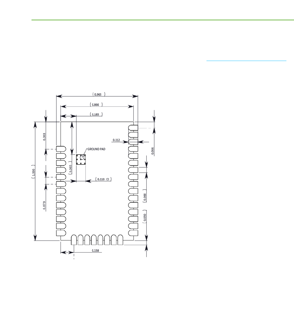
XBee/XBee-PRO XTend Compatible (XTC) RF Module User Guide 138
PCB design and manufacturing
Recommended footprint and keepout
We designed the XTC RF Module for surface mounting on the OEM printed circuit board (PCB). It has
castellated pads around the edges and one ground pad on the bottom. Mechanical drawings on page 14
includes a detailed mechanical drawing.
We recommend that you use the following PCB footprint for surface mounting. Dimensions are in inches.
The recommended footprint includes an additional ground pad that you must solder to the corresponding
pad on the XTC device. This ground pad transfers heat generated during transmit mode away from the

Recommended footprint and keepout
XBee/XBee-PRO XTend Compatible (XTC) RF Module User Guide 139
device’s power amplifier. The pad must connect through vias to a ground plane on the host PCB.
Connecting to planes on multiple layers will further improve the heat transfer performance and we
recommend doing this for applications that will be in transmit mode for sustained periods. We recommend
using nine 0.012 inch diameter vias in the pad as shown. Plug vias with epoxy or solder mask them on the
opposite side to prevent solder paste from leaking through the holes during reflow. Do not mask over the
ground pad.
Note The ground pad is unique to the XBee/XBee-PRO XTC and SX modules. This footprint is not
compatible with other SMT XBees.
Although the underside of the device is mostly coated with solder mask, we recommend that you leave the
copper layer directly below the device open to avoid unintended contacts. Most importantly, copper or vias
must not interfere with the three exposed RF test points on the bottom of the device shown in the
following keepout drawing. Observe the copper keepout on all layers of the host PCB, to avoid the
possibility of capacitive coupling that could impact RF performance.
Match the solder footprint to the copper pads, but you may need to adjust it depending on the specific
needs of assembly and product standards. We recommend a stencil thickness of 0.15 mm (0.005 in). Place
the component last and set the placement speed to the slowest setting.
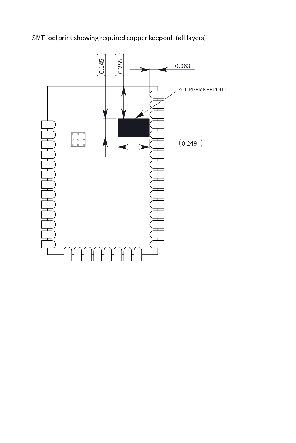
Design notes
XBee/XBee-PRO XTend Compatible (XTC) RF Module User Guide 140
Design notes
The following guidelines help to ensure a robust design.
Host board design
A good power supply design is critical for proper device operation. If the supply voltage is not kept within
tolerance, or is excessively noisy, it may degrade device performance and reliability. To help reduce noise,
we recommend placing both a 1 uF and 100 pF capacitor as near to VCC (pin 2) as possible. If you use a
switching regulator, we recommend switching frequencies above 500 kHz and you should limit power
supply ripple to a maximum 50 mV peak to peak.
As with all PCB designs, make power and ground traces thicker than signal traces and make them able to
comfortably support the maximum current specifications. Ground planes are preferrable.

Design notes
XBee/XBee-PRO XTend Compatible (XTC) RF Module User Guide 141
Improve antenna performance
The choice of antenna and antenna location is important for optimal performance. In general, antenna
elements radiate perpendicular to the direction they point. Thus a vertical antenna, such as a dipole, emit
across the horizon.
Metal objects near the antenna cause parasitic coupling and detuning, preventing the antenna from
radiating efficiently. Metal objects between the transmitter and receiver can also block the radiation path
or reduce the transmission distance, so position external antennas away from them as much as possible.
Some objects that are often overlooked are:
lMetal poles
lMetal studs or beams in structures
lConcrete (reinforced with metal rods)
lMetal enclosures
lVehicles
lElevators
lVentilation ducts
lLarge appliances
lBatteries
lTall electrolytic capacitors
RF pad version
The RF Pad is a soldered antenna connection. The RF signal travels from pin 36 on the module to the
antenna through a single ended RF transmission line on the PCB. This line should have a controlled
impedance of 50 Ω.
For the transmission line, we recommend either a microstrip or coplanar waveguide trace on the PCB. We
provide a microstrip example below, because it is simpler to design and generally requires less area on the
host PCB than coplanar waveguide.
We do not recommend using a stripline RF trace because that requires routing the RF trace to an inner
PCB layer, and via transitions can introduce matching and performance problems.
The following figure shows a layout example of a microstrip connecting an RF Pad module to a through
hole RPSMA RF connector.
lThe top two layers of the PCB have a controlled thickness dielectric material in between.
The second layer has a ground plane which runs underneath the entire RF Pad area. This
ground plane is a distance d, the thickness of the dielectric, below the top layer.
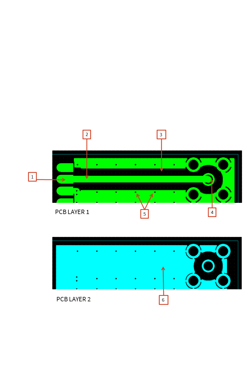
Design notes
XBee/XBee-PRO XTend Compatible (XTC) RF Module User Guide 142
lThe top layer has an RF trace running from pin 36 of the module to the RF pin of the
RPSMA connector. The RF trace's width determines the impedance of the transmission
line with relation to the ground plane. Many online tools can estimate this value, although
you should consult the PCB manufacturer for the exact width. Assuming d= 0.025 in, and
that the dielectric has a relative permittivity of 4.4, the width in this example will be
approximately 0.045 in for a 50 Ωtrace. This trace width is a good fit with the module
footprint's 0.060 in pad width.
We do not recommend using a trace wider than the pad width, and using a very narrow trace can cause
unwanted RF loss. The length of the trace is minimized by placing the RPSMA jack close to the module. All
of the grounds on the jack and the module are connected to the ground planes directly or through closely
placed vias. Space any ground fill on the top layer at least twice the distance d(in this case, at least 0.050
in) from the microstrip to minimize their interaction.

Recommended solder reflow cycle
XBee/XBee-PRO XTend Compatible (XTC) RF Module User Guide 143
Number Description
1 XBee pin 36
2 50 Ωmicrostrip trace
3 Back off ground fill at least twice the distance between layers 1 and 2
4 RF connector
5 Stitch vias near the edges of the ground plane
6 Pour a solid ground plane under the RF trace on the reference layer
Implementing these design suggestion will help ensure that the RFPad module performs to specifications.
Recommended solder reflow cycle
The following table provides the recommended solder reflow cycle. The table shows the temperature
setting and the time to reach the temperature; It does not show the cooling cycle.
Time (seconds) Temperature (degrees C)
30 65
60 100
90 135
120 160
150 195
180 240
210 260
The maximum temperature should not exceed 260°C.

Flux and cleaning
XBee/XBee-PRO XTend Compatible (XTC) RF Module User Guide 144
The XTC device will reflow during this cycle, and therefore must not be reflowed upside down. Take care
not to jar the XTC while the solder is molten, as this can remove components under the shield from their
required locations.
The device has a Moisture Sensitivity Level (MSL) of 3. When using this product, consider the relative
requirements in accordance with standard IPC/JEDEC J-STD-020.
In addition, note the following conditions:
a. Calculated shelf life in sealed bag: 12 months at < 40°C and < 90% relative humidity (RH).
b. Environmental condition during the production: 30°C /60% RH according to IPC/JEDEC J-
STD-033C, paragraphs 5 through 7.
c. The time between the opening of the sealed bag and the start of the reflow process
cannot exceed 168 hours if condition b) is met.
d. Baking is required if conditions b) or c) are not met.
e. Baking is required if the humidity indicator inside the bag indicates a RH of 10% more.
f. If baking is required, bake modules in trays stacked no more than 10 high for 4-6 hours at
125°C.
Flux and cleaning
We recommend that you use a “no clean” solder paste in assembling these devices. This eliminates the
clean step and ensures that you do not leave unwanted residual flux under the device where it is difficult
to remove. In addition:
lCleaning with liquids can result in liquid remaining under the device or in the gap between
the device and the host PCB. This can lead to unintended connections between pads.
lThe residual moisture and flux residue under the device are not easily seen during an
inspection process.
Rework
Once you mount the device, do not perform rework on the XTC device (for example, removing it from the
host PCB).
Any modification to the device voids the warranty coverage and certifications.