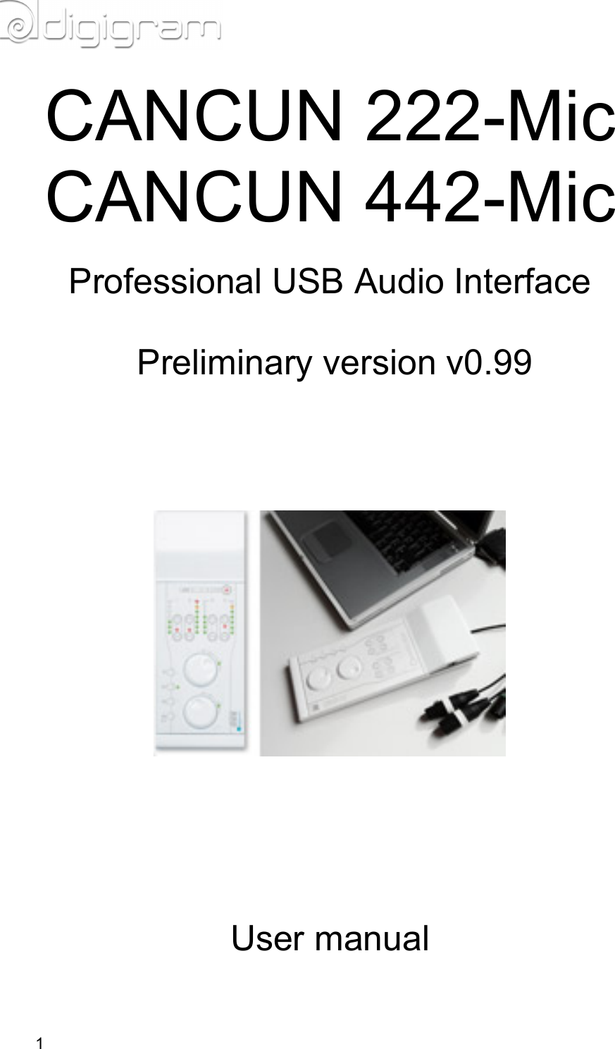
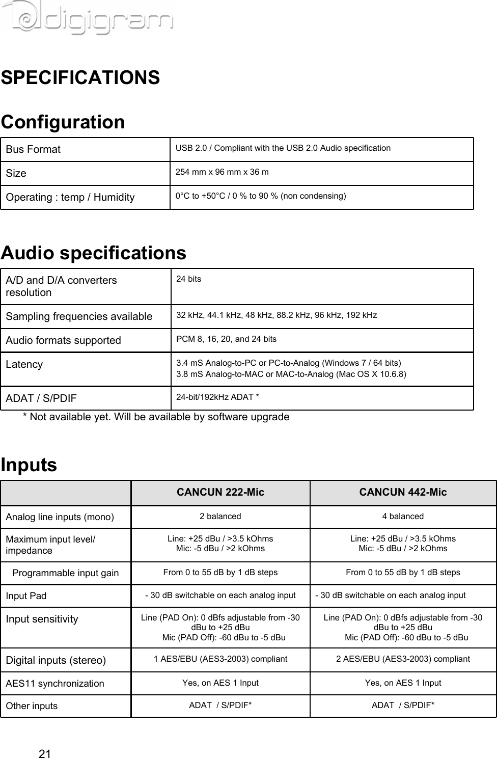
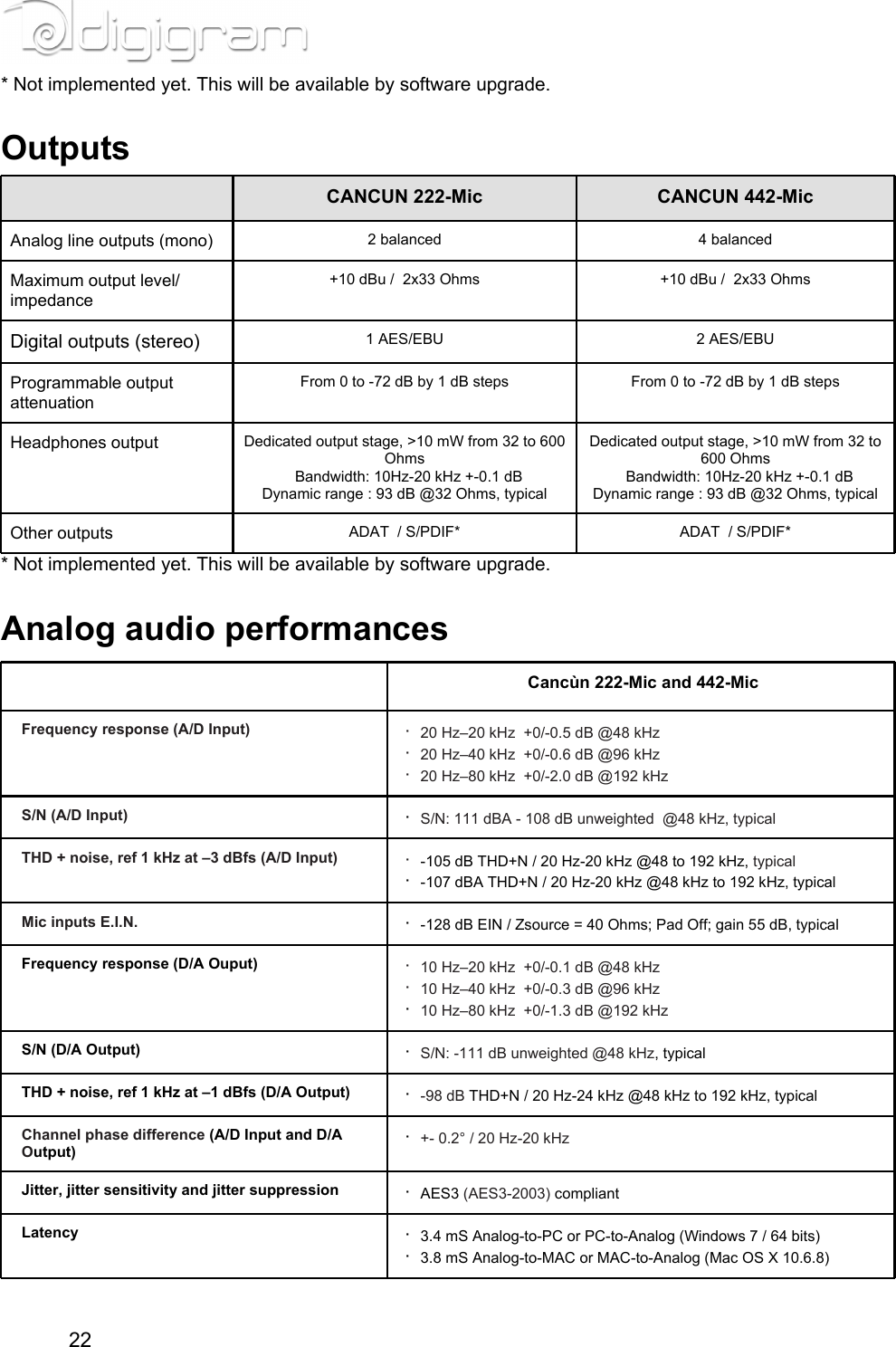
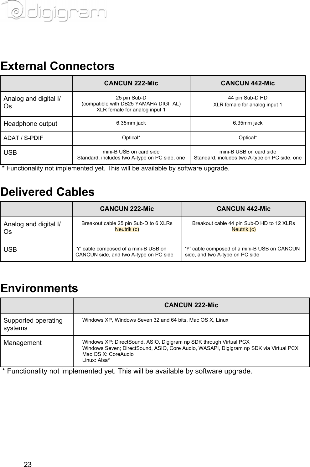
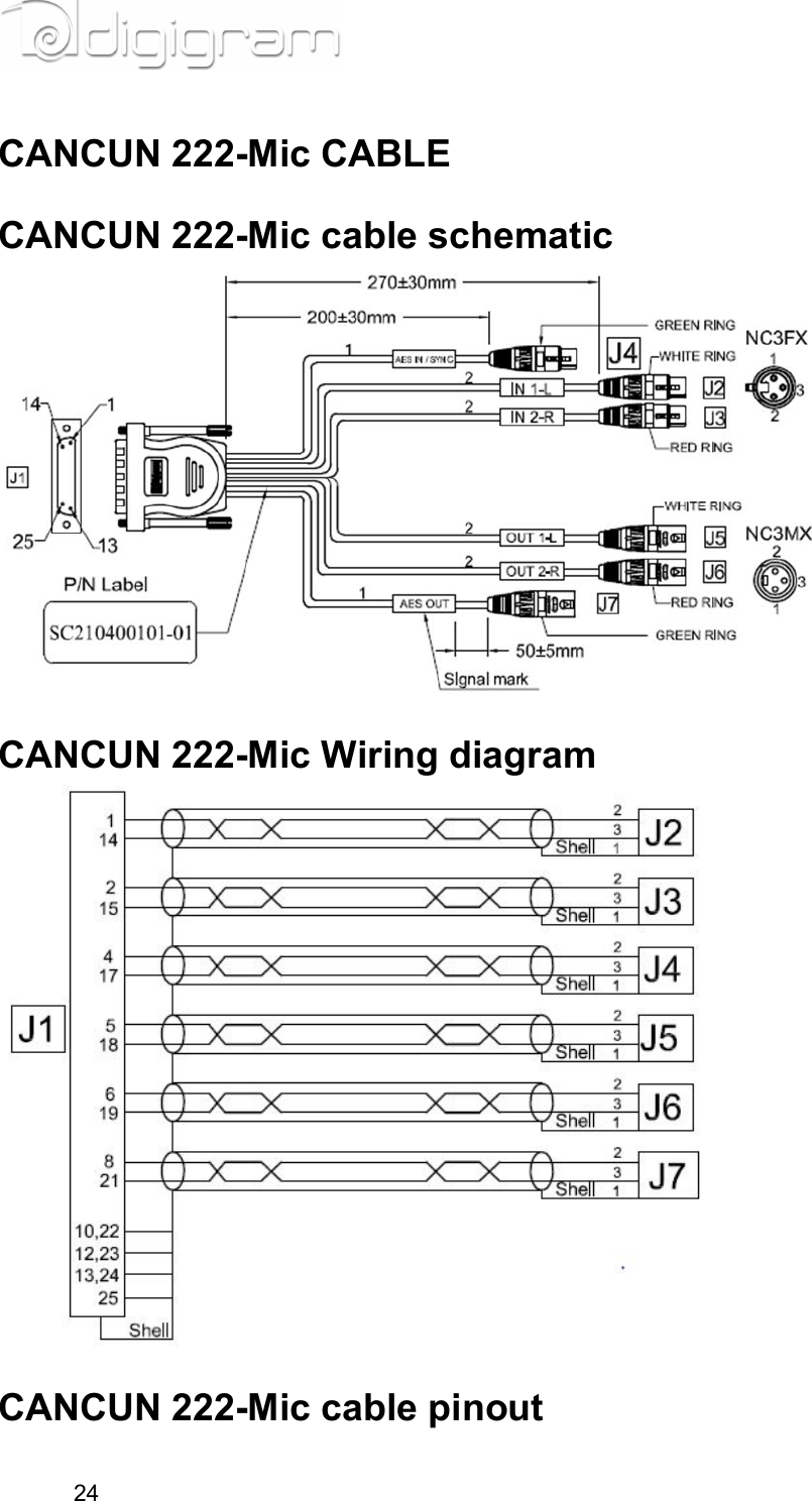
Digigram CANCUN Professional USB Audio Interface User Manual Manual
Digigram Professional USB Audio Interface Manual
UserManual.wiki
>
Digigram
>
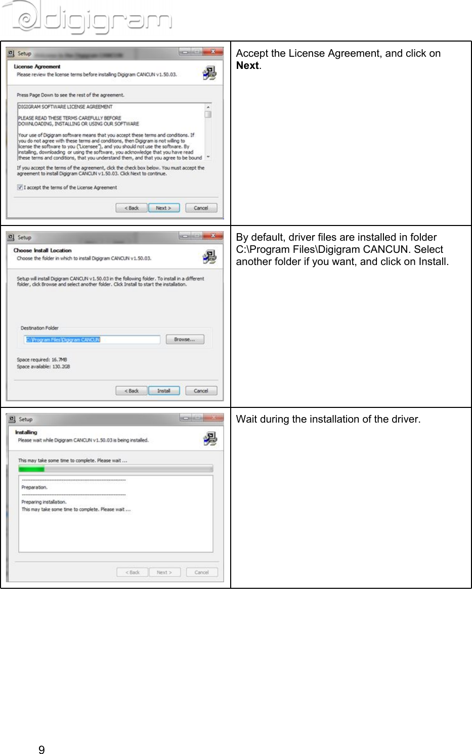
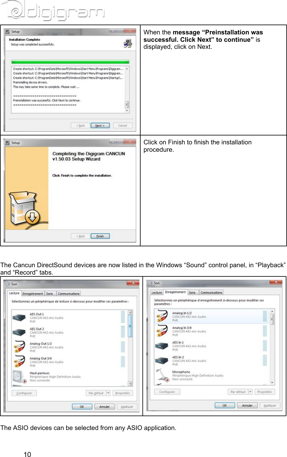
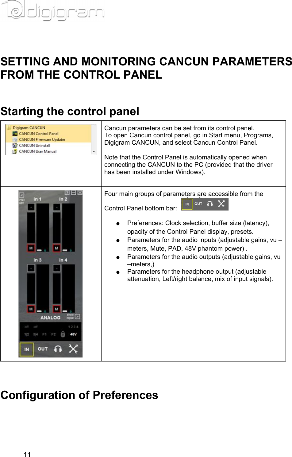
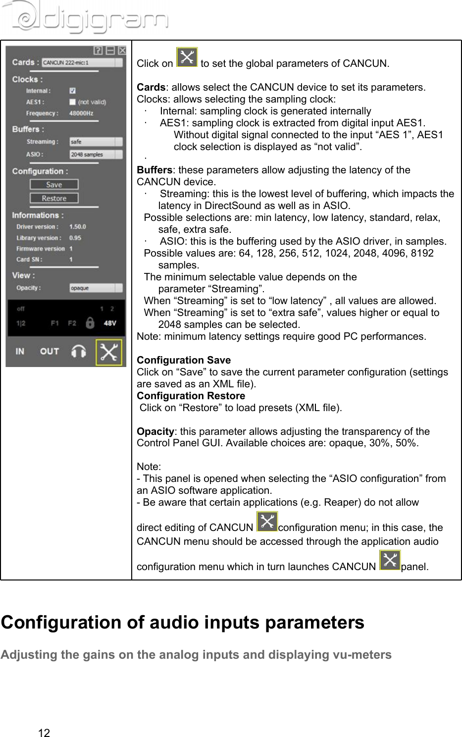
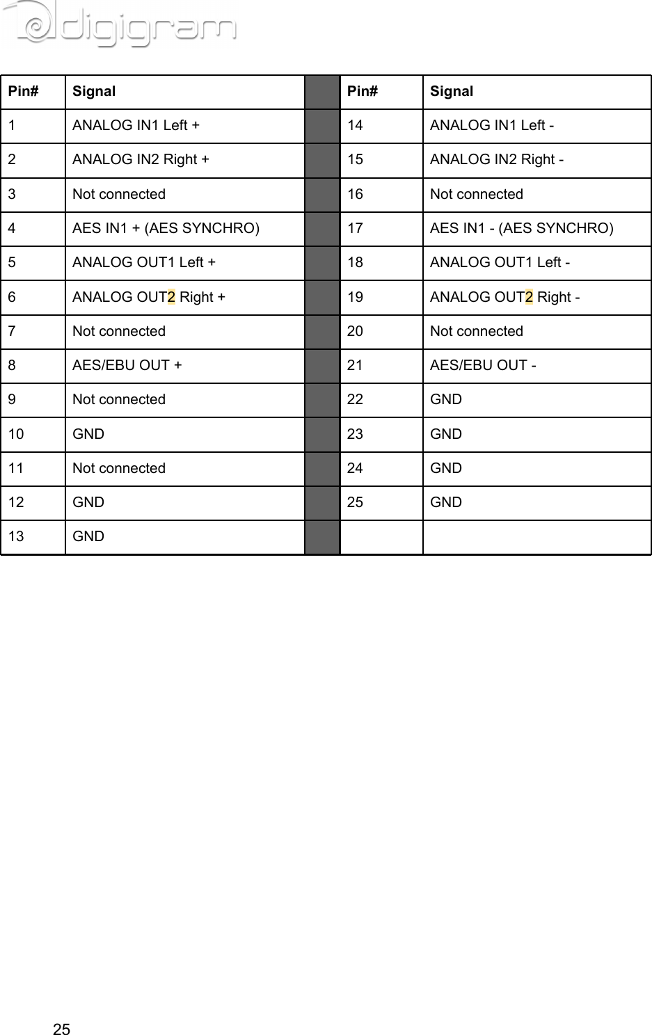
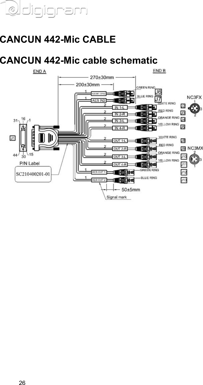
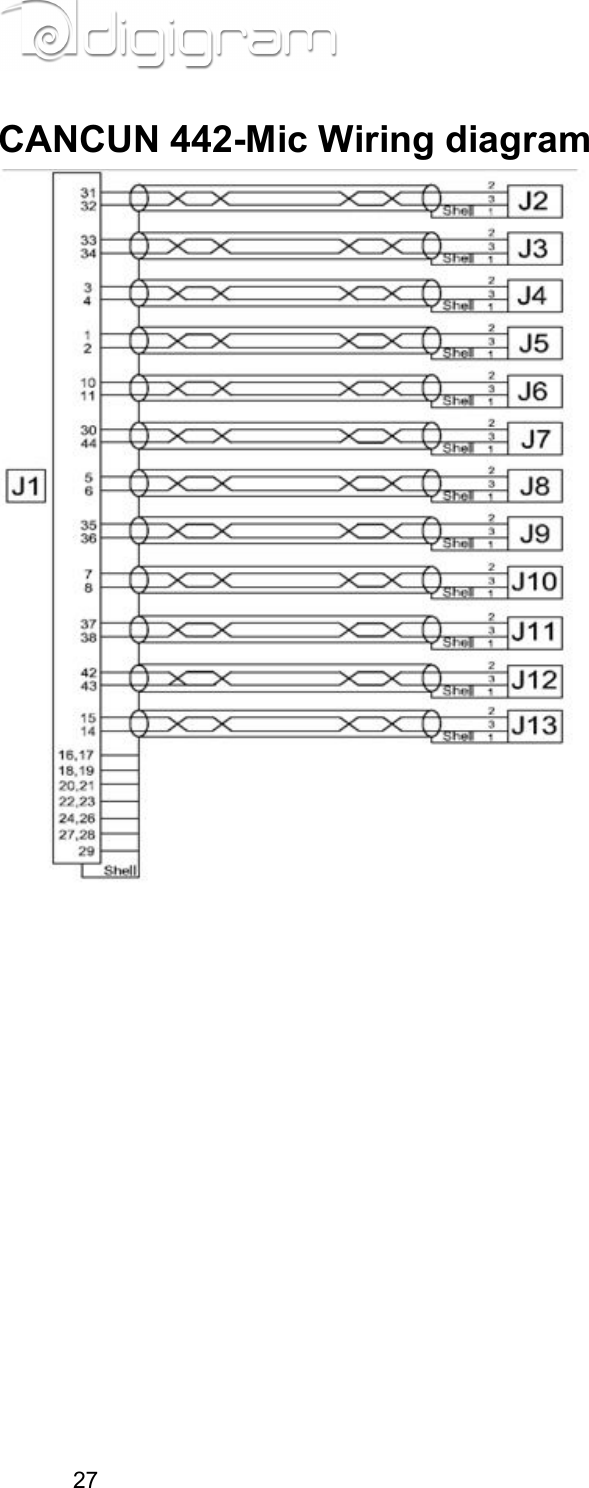
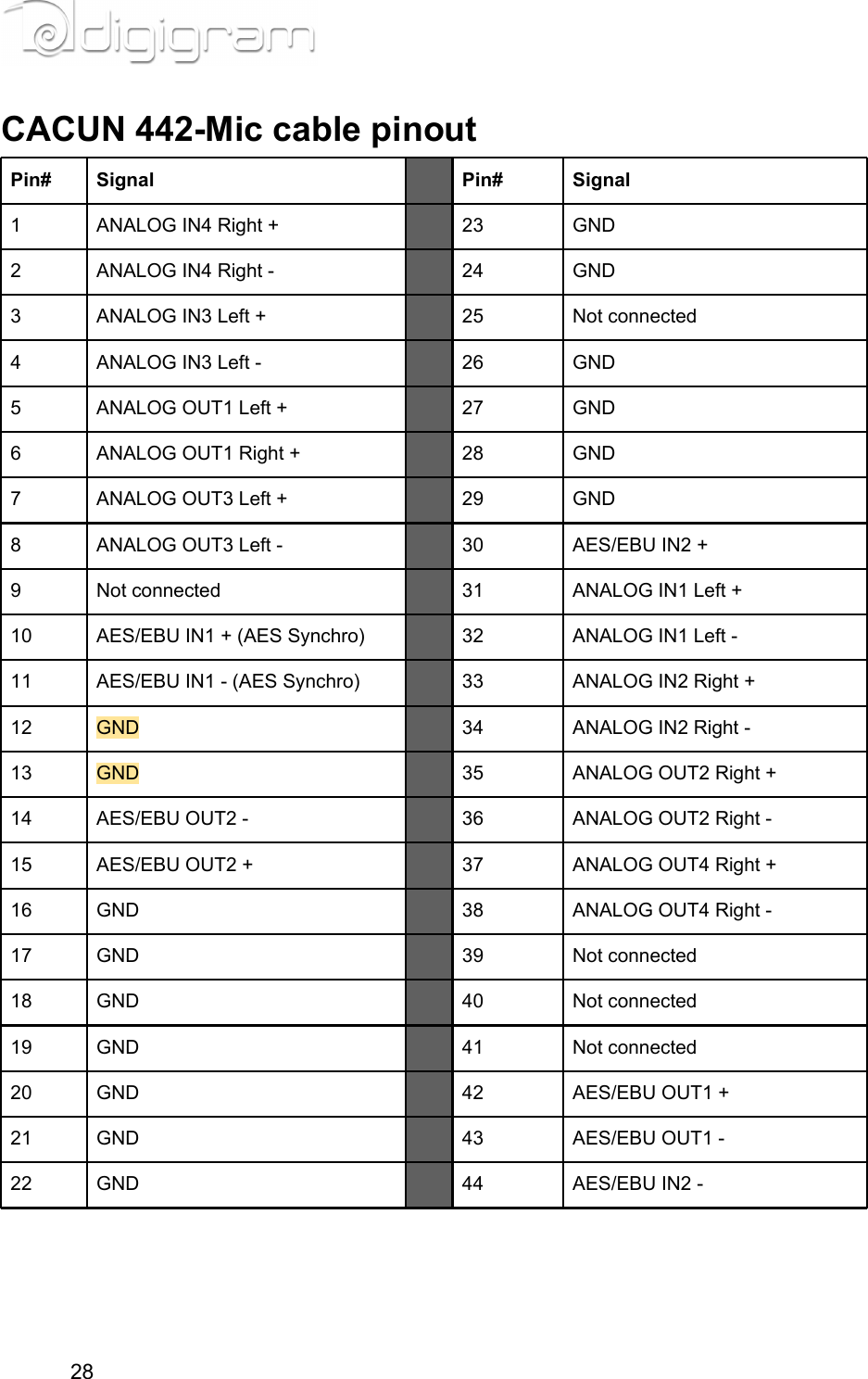
CANCUN User Manual
Manual
Navigation menu
Upload a User Manual
Namespaces
Wiki Guide
HTML
PDF
Info
Views
User Manual
Discussion / Help
Navigation