Digigram ES8AES Audio Networking Device User Manual ES AES Rev2 0 FCC
Digigram Audio Networking Device ES AES Rev2 0 FCC
UserManual.wiki
>
Digigram
>
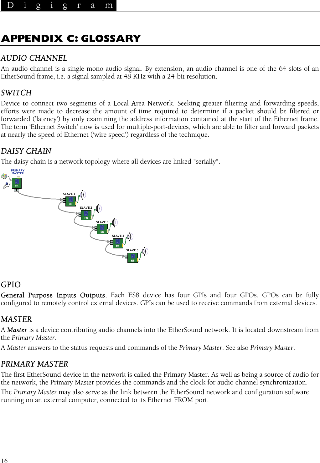
ES8AES User Manual
Manual
Navigation menu
Upload a User Manual
Namespaces
Wiki Guide
HTML
PDF
Info
Views
User Manual
Discussion / Help
Navigation