Digigram ES8AES Audio Networking Device User Manual ES AES Rev2 0 FCC
Digigram Audio Networking Device ES AES Rev2 0 FCC
Digigram >
Manual

Digigram
Networking Your Sound
ES881
ES1241
E S 16161
USER’SMANUAL
MANUEL UTILISATEUR
EtherSound ES881, ES1241 & ES16161
Ethernet Audio Bridges
Important Safety Information
read carefully before using this equipment!
Follow these instructions and keep them in a safe place! Keep in mind that damages due to failure to
observe the instructions contained in this manual are not covered by warranty.
Instructions importantes de sécurité
lire soigneusement avant d'utiliser l'équipement!
Lisez et suivez ces instructions. Conservez les pour consultation ultérieure! Les dommages dus au
non-respect des instructions contenues dans ce manuel ne sont pas couverts par la garantie.
Wichtige Sicherheitshinweise
vor Inbetriebnahme des Gerätes sorgfältig lesen!
Befolgen Sie die Anweisungen und bewahren Sie sie für spätere Fragen auf! Bei Schäden, die durch
Nichtbeachten dieser Bedienungsanleitung verursacht werden, erlischt der Garantieanspruch!
Throughout this manual,
the lightning bolt triangle is
used to alert the user to the
risk of electric shock.
The exclamation point
triangle is used to alert the
user to important operating
or maintenance instructions.
Do Not Open the Cabinet
There are no user-serviceable
components inside this product.
Opening the cabinet may present a shock hazard,
and any modification to the product will void
your warranty. If it is necessary to open the device
for maintenance or advanced configuration
purposes, this is to be done by qualified personnel
only after disconnecting the power cord and
network cables!
Power supply
The device is to be connected only to a
power supply as specified in this
manual and marked on the equipment. This
equipment must be earthed!
Do not block any of the ventilation openings!
Humidity
To reduce the risk of fire or shock, do not expose
this device to rain or moisture. Do not place
objects filled with liquid on this device.
Installation Location
To ensure proper operation and to avoid safety
hazards, the device must be installed in a 19“ rack
mount chassis. If this is not possible, place it on a
firm and level surface. Avoid installation in
extremely hot or cold locations, or in an area that
is exposed to direct sunlight or heating
equipment. Avoid moist or humid locations.
Cleaning
Clean only with a soft, dry cloth. If necessary,
after disconnecting the unit’s cables, wipe it with a
soft cloth dampened with mild soapy water, then
with a fresh cloth with clean water. Wipe dry
immediately with a dry cloth. NEVER use
benzene, aerosol cleaners, thinner, alcohol or any
other volatile cleaning agent. Do not use abrasive
cleaners, which may damage the finish of metal or
other parts.
Refer all servicing to qualified service
personnel.
Servicing is required when the apparatus has been
damaged in any way, such as power supply cord
or plug is damaged, liquid has been spilled, the
apparatus has been exposed to rain or moisture,
does not operate normally, or has been dropped.
Moving the device
Before moving the unit, be certain to disconnect
any cables that connect with other components.
Ne pas ouvrir l’appareil
L'ouverture du coffret peut produire
un risque de choc électrique, et toute
modification du produit annule votre garantie. S'il
est nécessaire d'ouvrir l'appareil pour l'entretien
ou la configuration avancée, cela doit être fait par
du personnel qualifié, après avoir débranché le
cordon d'alimentation et les câbles réseaux !
Alimentation
Il est primordial de connecter
l'appareil à une alimentation
électrique telle que spécifiée dans ce
manuel d´utilisateur et sur le matériel même.
Cet équipement doit être raccordé à la terre !
N'obstruer aucune ouverture de ventilation !
Humidité
Afin de réduire les risques de feu ou de choc,
n'exposez pas cet appareil à la pluie ou l'humidité.
Ne placez pas d´objet contenant un liquide sur
l'appareil.
Installation, mise en place
Afin d'assurer le fonctionnement correct et de
minimiser les risques potentiels liés à la sécurité,
l'appareil doit être installé dans une baie de
montage de type 19 pouces. Si cela ne vous est
pas possible, placez le sur une surface solide et
plane.
Evitez une installation dans des endroits très
chauds ou très froids ainsi que dans des lieux
exposés directement au soleil. Evitez les lieux
présentant un excès d'humidité.
Nettoyage
Nettoyez uniquement avec un chiffon doux et sec.
Si nécessaire, après avoir débranché le cordon
d´alimentation, essuyez-le avec un chiffon doux
humidifié avec de l´eau savonneuse puis rincez le
á l´aide d un chiffon propre et d´eau claire.
Séchez-le immédiatement avec un chiffon sec.
N'utilisez JAMAIS d´essence, de nettoyants en
aérosols, d´alcool ou tout autre agent nettoyant
volatile. N'utilisez pas de produits nettoyants
abrasifs qui pourraient endommager les finitions
métalliques ou d´autres pièces.
Réparation
Lorsque l'appareil a été endommagé quelle qu'en
soit la cause ou qu'il ne fonctionne pas
normalement, toute réparation doit être effectuée
par du personnel qualifié. Avant de transporter
l´unité, assurez-vous d´avoir bien déconnecté le
cordon d'alimentation ainsi que tous les câbles la
reliant à d´autres appareils.
Gerät nicht öffnen
Öffnen des Geräts kann eine
Gefährdung durch Stromschlag und
Erlöschen der Garantie zur Folge haben.
Reparaturarbeiten und Änderungen der
Hardwarekonfiguration dürfen nur von
qualifiziertem Personal nach entfernen der Strom-
und Netzwerkkabel durchgeführt werden.
Stromversorgung
Das Gerät darf nur mit der in dieser
Bedienungsanleitung und auf dem
Gerät angegebenen Stromversorgung
betrieben werden. Erdung ist zu gewährleisten!
Belüftungsschlitze nicht verdecken!
Wasser und Feuchtigkeit
Um Brand- oder Stromschlagrisiken zu
vermeiden, darf das Gerät nicht mit Feuchtigkeit
in Berührung kommen.
Aufbau des Geräts
Um den einwandfreien Betrieb zu gewährleisten
und Sicherheitsrisiken zu vermeiden, muss das
Gerät in einem 19-Zoll Baugruppenrahmen
montiert werden. Nur wenn dies nicht möglich
ist, stellen Sie das Gerät auf einen festen,
waagerechten Untergrund. Meiden Sie Standorten
in den Nähe von Wärme- oder
Feuchtigkeitsquellen sowie direkte
Sonneneinstrahlung.
Reinigen des Geräts
Säubern Sie das Gerät nur mit einem weichen,
trockenen Tuch. Bei Bedarf verwenden Sie ein mit
mildem Seifenwasser befeuchtetes Tuch, nachdem
Sie die Netzanschlusskabel aus der Steckdose
gezogen haben, anschliessend ein weiches, mit
klarem Wasser befeuchtetes Tuch. Trocken Sie
das Gerät sofort im Anschluss. Keinesfalls Benzol,
Verdünner oder sonstige starke Lösungsmittel
oder Scheuerreiniger verwenden, da hierdurch
das Gehäuse beschädigt werden könnte.
Lassen Sie etwaige Reparaturen nur von
qualifizierten Fachleuten durchführen!
Sollten das Netzkabel oder der Netzstecker
beschädigt sein, oder sollte das Gerät selbst
beschädigt worden sein (z. B. durch Eindringen
von Feuchtigkeit durch Fall auf den Boden), oder
sollte es nicht ordnungsgemäss funktionieren oder
eine deutliche Funktionsabweichung aufweisen,
so ist es von qualifizierten Fachleuten zu
reparieren.

EtherSound ES881, ES1241 & ES16161
Ethernet Audio Bridges
2
TABLE OF CONTENTS
INFORMATION FOR THE USER
........................................................................................................................................ 3
KEY FEATURES
................................................................................................................................................................................... 4
OVERVIEW
............................................................................................................................................................................................... 4
Contents of this package .......................................................................................................................................................................4
The ES881, ES1241, and ES16161 front panels..........................................................................................................................5
ES881, ES1241, and ES16161 back panels ..................................................................................................................................6
INSTALLATION
.................................................................................................................................................................................. 8
Before mounting devices in a rack….................................................................................................................................................8
Internal settings .................................................................................................................................................................................8
Connecting your EtherSound device ...................................................................................................................................................8
Power supply.......................................................................................................................................................................................8
Network...............................................................................................................................................................................................8
Example 1: bi-directional point-to-point transmission of eight audio channels ........................................................8
Example 2: more complex architectures.............................................................................................................................8
Synchronization..................................................................................................................................................................................9
Connecting a computer to manage the EtherSound network..............................................................................................9
Audio.....................................................................................................................................................................................................9
GPIO......................................................................................................................................................................................................9
Serial port (RS232 on DB9) ....................................................................................................................................................... 10
Remote set-up by means of configuration software ............................................................................................................ 10
Firmware update................................................................................................................................................................................... 10
SPECIFICATIONS
.............................................................................................................................................................................11
Configuration .......................................................................................................................................................................................... 11
Inputs/outputs ........................................................................................................................................................................................ 11
Connectivity............................................................................................................................................................................................. 11
Synchronization...................................................................................................................................................................................... 11
APPENDIX A: GPIO CONNECTORS
............................................................................................................................12
General Purpose Inputs (GPIs) .......................................................................................................................................................... 12
GPI #1............................................................................................................................................................................................... 12
GPI #1............................................................................................................................................................................................... 12
GPI #3 & GPI #4........................................................................................................................................................................... 12
GPI optocoupler specifications.................................................................................................................................................... 13
General Purpose Outputs (GPOs)..................................................................................................................................................... 13
GPO relay specifications............................................................................................................................................................... 13
APPENDIX B: SETTING THE INTERNAL JUMPER
.......................................................................................14
Jumper location on the main board................................................................................................................................................. 14
Select sampling frequency ........................................................................................................................................................... 15
APPENDIX C: GLOSSARY
......................................................................................................................................................16

EtherSound ES881, ES1241 & ES16161
Ethernet Audio Bridges
3
INFORMATION FOR THE USER
This equipment has been tested and found to comply with the limits for a CLASS B digital device, pursuant to Part 15 of the FCC
Rules and with the following European and international Standards for:
Electrical safety: Electromagnetic Compatibility:
Europe : EN60950, 3rd edition
European Directive 73/23/CEE “Low Voltage Directive“
International: IEC 60950, 3rd edition
Europe: EN55022:1998 + A1:2000, Class B / EN55024 : 1998 + A1:2001
European Directive 89/336/CEE on electromagnetic compatibility
International: CISPR22:1997 + A1:2000 CLASS B
United states: FCC rules-Part 15 Class B ( digital device )
In order to guarantee compliance with the above standards in an installation, the following must be done:
· the provided cables must not be modified.
· additional cables used must have their respective shield connected to each extremity.
The limits specified in the standards are designed to provide reasonable protection against harmful interference in a residential
installation. This equipment generates, uses and can radiate radio frequency energy and, if not installed and used in accordance with
the instruction, may cause harmful interference to radio communications. However, there is no guarantee that interference will not
occur in a particular installation.
If this equipment does cause harmful interference to radio or television reception, which can be determined by turning the equipment
off and on, the user is encouraged to try to correct the interference by one or more of the following measures:
* reorient or relocate the receiving antenna.
* increase the separation between the equipment and the receiver.
* connect the equipment into an outlet on a circuit different from that to which the receiver is connected.
* consult the dealer or an experienced audio/television technician for help.
Note: Connecting this device to peripheral devices that do not comply with CLASS B requirements or using an unshielded peripheral data
cable could also result in harmful interference to radio or television reception. The user is cautioned that any changes or modifications
not expressly approved by the party responsible for compliance could void the user’s authority to operate this equipment. To ensure
that the use of this product does not contribute to interference, it is necessary to use shielded I/O cables.
Copyright 2005 Digigram. All rights reserved.
No portion of this manual may be reproduced without prior written consent from Digigram. The copyright protection claimed here includes
photocopying, translation and/or reformatting of the information contained in this manual.
While every effort has been made to ensure accuracy, Digigram is not responsible for errors and omissions, and reserves the right to make improvements
or changes in the products and programs described without notice.
Digigram, EtherSound, ES881, ES1241, and ES16161 are registered trademarks or trademarks of Digigram S.A.. All other trademarks are property of their
respective holders.

D i g i g r a m
4
You have just acquired a Digigram EtherSound audio bridge
and we congratulate you!
Digigram EtherSound ES881 / ES1241 / ES16161 are equipped with AES/EBU interfaces including
hardware sample rate converters (SRC). They allow the realization of flexible and powerful EtherSound
networks.
The manual at hand will guide through installation and operation. For any software related issue, please
refer to the specific documentation provided in its on-line help.
For more information on EtherSound networks and wiring recommendations please consult the document
‘Creating EtherSound Networks’ (English), available on the enclosed CD-ROM or on our web site.
KEY FEATURES
ES881 :
• 4 AES/EBU digital stereo inputs inserted into 8 EtherSound channels
• 4 AES/EBU digital stereo outputs extracted from 8 EtherSound channels
ES1241 :
• 2 AES/EBU digital stereo inputs inserted into 4 EtherSound channels
• 6 AES/EBU digital stereo outputs extracted from 12 EtherSound channels
ES16161 :
• 8 AES/EBU digital stereo inputs inserted into 16 EtherSound channels
• 8 AES/EBU digital stereo outputs extracted from 16 EtherSound channels
• 1 Word Clock input
• 1 Word Clock output
• 19“ 1 RU enclosure
• Remote control and management via ‘EScontrol’ software
• XLR connectors (ES16161 : 4 Sub-D 25-pin connectors)
OVERVIEW
Contents of this package
The package consists of the following components:
• one ES881, ES1241 or ES16161 1U 19 inch rack device
• a power cord
• counterparts for the GPIO terminal blocks
• the User’s Manual at hand
• a CD-Rom with configuration and control software
EtherSound ES881, ES1241 & ES16161
Ethernet Audio Bridges
5
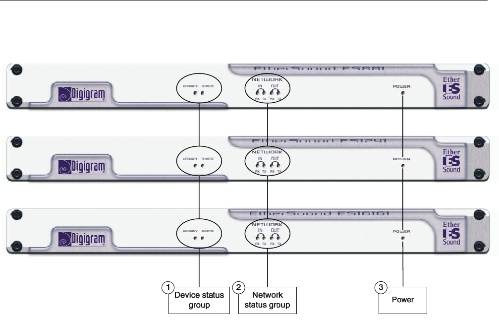
The ES881, ES1241, and ES16161 front panels
1. Device status group (two orange LEDs):
Primary
The first LED is called “Primary”. It shines when the device is the first ‘Master’ device in the EtherSound
network, thus the ‘Primary Master’ of the EtherSound network (see document on EtherSound for more
details on the ‘Primary Master’ concept)
Remote
The second diode is called “Remote”, it indicates that the configuration of the EtherSound channels is
carried out remotely
2. Network status group
These four green diodes light up when the devices are connected to the EtherSound network; as soon as a
network activity is detected, they start to flash indicating an activity on the two Ethernet ports (“IN” and
“OUT”); RX flashing means that data are received while TX flashing means that data are transmitted.
3. Power
This LED simply shows that the device is up and running!
D i g i g r a m
6
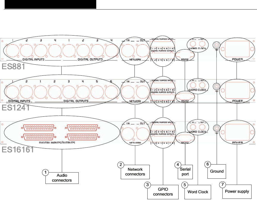
ES881, ES1241, and ES16161 back panels
1. Audio connectors
On ES881, four male XLR-3 connectors are used to output eight EtherSound channels on four AES/EBU
stereo outputs, four female XLR-3 connectors to input eight EtherSound channels on four AES/EBU stereo
inputs.
On ES1241, six male XLR-3 connectors are used to output twelve EtherSound channels on six stereo
AES/EBU stereo outputs, two female XLR-3 connectors to input four EtherSound channels on two AES/EBU
stereo inputs.
On ES16161, two female Sub-D 25-pin connectors are used to output sixteen EtherSound channels on eight
stereo AES/EBU stereo outputs, two female Sub-D 25-pin connectors to input sixteen EtherSound channels on
eight AES/EBU stereo inputs.
2. Network connectors
These two NeutrikTM EtherConTM RJ45 connectors allow of a steady and reliable connection to the EtherSound
network. The “IN” port receives the descending EtherSound stream (‘downstream’, coming from the ‘Primary
Master’) while the “OUT” port receives the ascending EtherSound stream (‘upstream’) and transmits it to the
“IN” port; for more details on the concepts of ‘upstream’ and ‘downstream’ please refer to the document
‘EtherSound Overview’, available on the enclosed CD-ROM and on our web site.

EtherSound ES881, ES1241 & ES16161
Ethernet Audio Bridges
7
3. GPIO connectors
These terminal blocks allow setup of external control and monitoring devices through configurable and
protected General Purpose Inputs and Outputs. See dedicated GPIO chapter for details.
Note: the GPIO port is managed by configuration software only.
4. Serial port
RS232 interface on DB9.
Note: The RS232 serial port management requires specific software.
5. Word clock synchronization
Two female BNC connectors , ‘Word Clock In’ and ‘Word Clock Out’, allow synchronization with an
external clock. For more details see the corresponding chapter.
6. Ground
Connect this ground bolt to the chassis of the mounting rack for a better grounding of the electronics, thus
ensuring immunity to electromagnetic interference.
7. Power supply
Power plug MUST be earthed properly.

D i g i g r a m
8
INSTALLATION
Before mounting devices in a rack…
Internal settings
On ES881, ES1241, and ES16161 the local sampling frequency is switchable by means of a jumper between
44.1 kHz and 48 kHz.
Preset default value is 48 kHz.
In case you need to change the default setting, please refer to appendix B of this manual.
Note: These operations require opening of the cabinet and shall be done by qualified personnel only.
Connecting your EtherSound device
It is recommended to establish all connections before powering up the device.
Power supply
Before plugging the power cord, make sure that:
• the power cord is not damaged
• the AC outlet used is properly earthed.
Just like for any other audio system, power the individual devices up following the audio path and power
down in the opposite direction.
Do not allow anything to rest on the power cable. Keep the power cable away from where people could trip
over it.
Network
The cable type most commonly used today is CAT5e. For more detailed information, please refer to the
document “Building ES Networks”, available on the enclosed CD-ROM and on our web site.
The network connections are established via two NeutrikTM EtherConTM RJ45 receptacles. Connection is very
easy: use the connector labeled “IN” to connect the descending EtherSound stream (downstream, coming from
the ‘Primary Master’), the connector labeled “OUT” to connect the ascending EtherSound stream (‘upstream’).
The NeutrikTM EtherConTM RJ45 provide secure connection through a latching system. To disconnect the cable
from the device, press the latch, then withdraw the cable while maintaining the latch pushed.
Example 1: bi-directional point-to-point transmission of eight audio channels
This application is very easy with EtherSound ES881, ES1241, and ES16161.
Connect a standard Ethernet cable between the “OUT” port of the first Ethernet bridge to the “IN” port of the
second Ethernet bridge. Bring into line the EtherSound channels on the two devices (see the on-line help of
the configuration software).
Example 2: more complex architectures
System topology may be daisy chain, star, or a combination of both. By default, the first device in a network,
such as an EtherSound ES881, provides the master clock for the entire network. Nevertheless, you have the
possibility to synchronize the ‘Primary Master’ on an external clock by using the ‘Word Clock In’ input and by
then providing this clock to the EtherSound bridges downstream from the ‘Primary Master’ passing through
the ‘Word Clock Out’ outputs.
Connect the “OUT” port with the “IN” port of the following EtherSound device.
Repeat this step for each device in the network. The maximum distance between two devices is 100 meters
(328 feet). Intermediate switches or fiber optic links may be used to considerably increase this distance.

EtherSound ES881, ES1241 & ES16161
Ethernet Audio Bridges
9
Synchronization
ES881, ES1241, and ES16161 support several synchronization modes.
Synchronization via:
• the network (except in ‘Primary Master’ mode)
• the ‘AES In 1’ input
• the Word clock input
If the equipment is ` Primary Master', it provides the clock for the network It can be synchronized on the
internal clock or on the signal connected to the “AES In 1”, or on the signal connected to the Word Clock
input. In the last case, these input signals must be synchronized with the Word Clock. If they are not
synchronized, it is necessary to insert a frequency conversion stage (SRC) from the configuration software.
Likewise, the insertion of the SRC is obligatory in the case of synchronization on the internal clock.
When the device is not in ‘Primary Master’ mode, it is synchronized on the signal coming from the network:
• the ‘Word Clock Out’ output allows synchronizing the devices connected on the ‘AES In 1’ inputs. In
this case it is not necessary to insert an SRC stage.
• If the devices connected to the AES/EBU are not synchronized on the network, sample rate conversion
(SRC) is required.
Use the configuration software provided to set these parameters.
Connecting a computer to manage the EtherSound network
To connect a PC directly to an ES881, it must be equipped with a network card. Use an Ethernet cable to
connect the network card to the “IN” port of the Primary Master.
You can as well access the Primary Master through a regular Ethernet network.
Audio
The pinout used on the XLRs is standard: pin 1 carries the signal ground, pin 2 carries the positive signal
(“hot”, +) and pin 3 carries the negative signal (“cold”, -).
GPIO
ES881, ES1241, and ES16161 are shipped with four GPIs and four GPOs on terminal blocks, counterparts are
supplied. For details see Appendix A.
D i g i g r a m
10
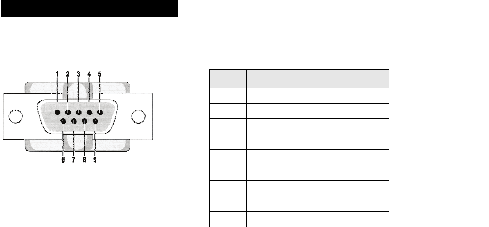
Serial port (RS232 on DB9)
ES881, ES1241, and ES16161 dispose of a serial ES16161 RS232 male port on the rear panel. Use this port to
connect any compatible device. For pinout allocation details, please refer to the figure and table above.
Note: The RS232 serial port management requires specific software.
Remote set-up by means of configuration software
Use of the configuration software allows for the management of all devices on the EtherSound network; for
software details, please refer to the on-line help file.
ES881, ES1241, and ES16161 are shipped with a CD-ROM containing the EtherSound driver and the
Digigram configuration software, EScontrol. To install this software, you must first add the EtherSound driver
to your system. A window lists the instructions you must follow to achieve this step.
Next, launch setup.exe on a PC connected to an EtherSound network. An InstallShield Wizard will guide you
through the installation process.
ES881, ES1241, and ES16161 may also be managed through configuration software edited by Digigram
development partners.
To uninstall the software go to Add/Remove programs in the Windows Control Panel.
Firmware update
Digigram may decide to publish firmware updates. It may then become necessary to upgrade your devices. In
this case please refer to the respective documentation provided with the firmware upgrade tool.
Pin # Description
1 not connected
2 RxD (received data)
3 TxD (transmitted data)
4 not connected
5 signal ground
6 not connected
7 RTS (request to send)
8 CTS (clear to send)
9 not connected
EtherSound ES881, ES1241 & ES16161
Ethernet Audio Bridges
11
SPECIFICATIONS
Configuration
Size 1U 19” rack : 43.9 x 482.6 x 297.1 mm
Power supply 100 - 240 VAC, 47-63 Hz
switching-mode, automatic voltage detection
WARNING: Do not open the power supply module. It contains hazardous
voltages.
There are no user-serviceable parts inside
Temp / humidity
(non-condensing)
Operating:
Storage:
0 °C - 50 °C / 0% - 95%
-5 °C – 70 °C / 0% - 95%
Power consumption ES881/ES1241/ES16161 : 0.23 A at 100 V, 0.125 A at 240 V
Net weight ∼3,1 kg (∼6.85 lbs)
Entrées/sorties
EtherSound ES881 EtherSound ES1241 EtherSound ES16161
Digital audio
AES/EBU 3
4 stereo inputs
4 stereo outputs
2 stereo inputs
6 stereo outputs
8 stereo inputs
8 stereo outputs
With one hw sample rate converter per input,
conversion ratio 1:3 to 3:1, up to 96 kHz
Impedance 110 Ω 110 Ω 110 Ω
Sampling frequencies
available 48 kHz or 44.1 kHz
Connectivity
EtherSound ES881 EtherSound ES1241 EtherSound ES16161
Digital audio 4 female XLR-3 and
4 male XLR-3
2 female XLR-3 and
6 male XLR-3 4 female Sub-D 25
EtherSound 2 female EtherCon RJ45 compatible (connections “IN”/“OUT”)
GPIO 4 optocoupled inputs and 4 relay outputs on 8-point terminal blocks
Serial ports 1 RS232 on DB9
Synchronization
Clock source If ‘Primary Master’ in an EtherSound network:
Internal, Word Clock or on ‘AES IN 1’ input
If not ‘Primary Master’: EtherSound network, Word Clock or on ‘AES IN 1’
input (synchronized on the ‘Primary Master’ clock)
D i g i g r a m
12
APPENDIX A: GPIO CONNECTORS
ES881, ES1241, and ES16161 feature four optocoupled GPIs and four relay GPOs. GPIs
allow sending commands to the EtherSound configuration software, GPOs can be used by
the EtherSound configuration software for remote control of external devices.
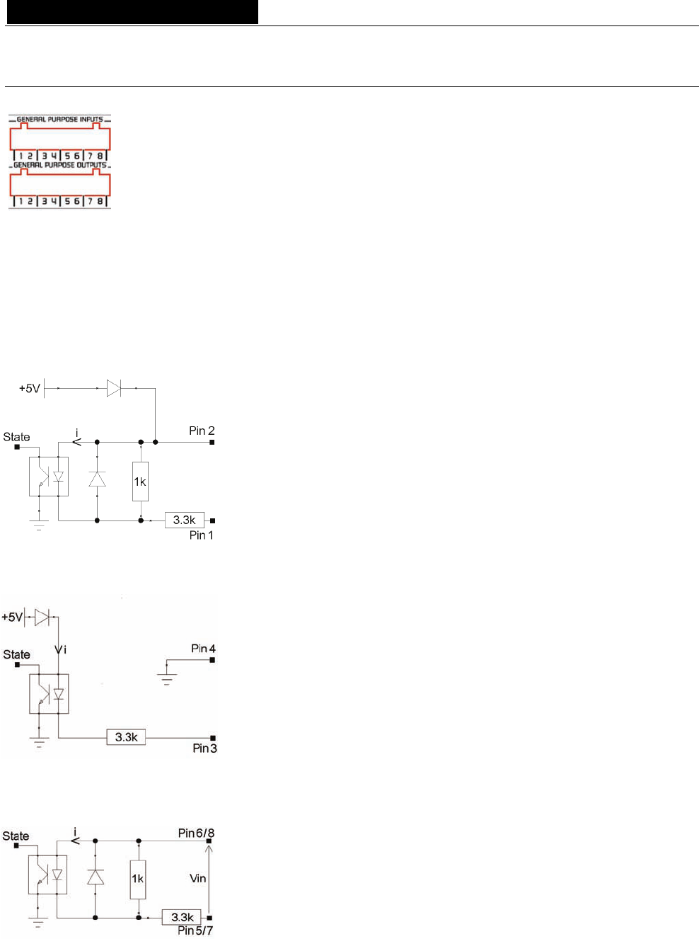
The GPIO pins are labeled 1 through 8 on the rear panel as illustrated.
General Purpose Inputs (GPIs)
Schematic diagrams show the particular design for each GPI. The GPI status can be either “1” or “0”. It is read
“0” as soon as the system connected to the GPI creates the current labeled “i” on the scheme. Otherwise it is
read “1”. Different GPI designs allow for multiple ways to establish this current, thus offering utmost flexibility
in system configuration to best meet your needs.
Note: Pin 2 delivering +5 V electric potential and pin 4 being connected to ground may also be used in the
configuration of other GPIs.
GPI #1
GPI #1 uses pins 1 & 2
Pin 2 delivers +5 V electric potential. This pin may serve as a source to create a
current flow for GPI #3 and GPI #4.
Switching the GPI state to 0:
Pin 1 is to be connected to ground to establish the “i” current, typically by
connecting it to pin 4.
GPI #1
GPI #3 uses pins 1 & 4
Switching the GPI state to 0:
Pin 3 is to be connected to ground to establish the “i” current, typically by
connecting it to pin 4.
GPI #3 & GPI #4
GPI #3 uses pins 5 & 6, GPI #4 uses pins 7 & 8.
Switching the GPI state to 0:
A current flow is to be established from pin 6 to pin 5 (GPI #3) or from pin 8 to
pin 7 (GPI #4).

EtherSound ES881, ES1241 & ES16161
Ethernet Audio Bridges
13
GPI optocoupler specifications
minimum current imin to switch GPI 0,5 mA
Maximum current imax supported 50 mA
i calculation rule (GPi #3 & #4) i (mA) = 3,3
1,2 - Vin
Maximum voltage Vin supported 50 Vdc
Maximum reverse voltage Vin supported 6 V
General Purpose Outputs (GPOs)
The ES8 GPOs are relay outputs. They feature two pins each and are all configured the same way. Pins 1 & 2
belong to GPO #1, 3 & 4 to GPO #2, 5 & 6 to GPO #3, and 7 & 8 to GPO #4.
It responds to commands of configuration and management software sent via the Primary Master. If written at
“1”, the GPO closes the linked open collector. If written at “0”, the GPO opens the linked open collector.
GPO relay specifications
Maximum power switching capability 10 W
Maximum switching current 500 mAdc
Maximum carrying current 1 Adc
Maximum switching voltage 100 Vdc
Typical life expectancy (switching max power) 106 operations
D i g i g r a m
14
APPENDIX B: SETTING THE INTERNAL JUMPER
These settings shall be executed by qualified personnel only!
Tools required:
• a #1 Pozidriv screwdriver
• an ESD-preventive wrist strap
• a small flat blade screwdriver
Electrostatic discharge (ESD) can damage several components on the board. To avoid such damage in
handling the board, take the following precautions:
Bring the device and everything that contacts it to ground potential by providing a conductive surface and
discharge paths. As a minimum, observe these precautions:
• Disconnect all power and signal sources.
• Place the device on a grounded conductive work surface.
• Ground yourself via a grounding wrist strap or by holding a grounded object.
• Ground any tools that will contact the device.
• Unscrew the eight flat-head Pozidriv screws (four on top-side,
four on bottom-side) counterclockwise and open the cabinet.
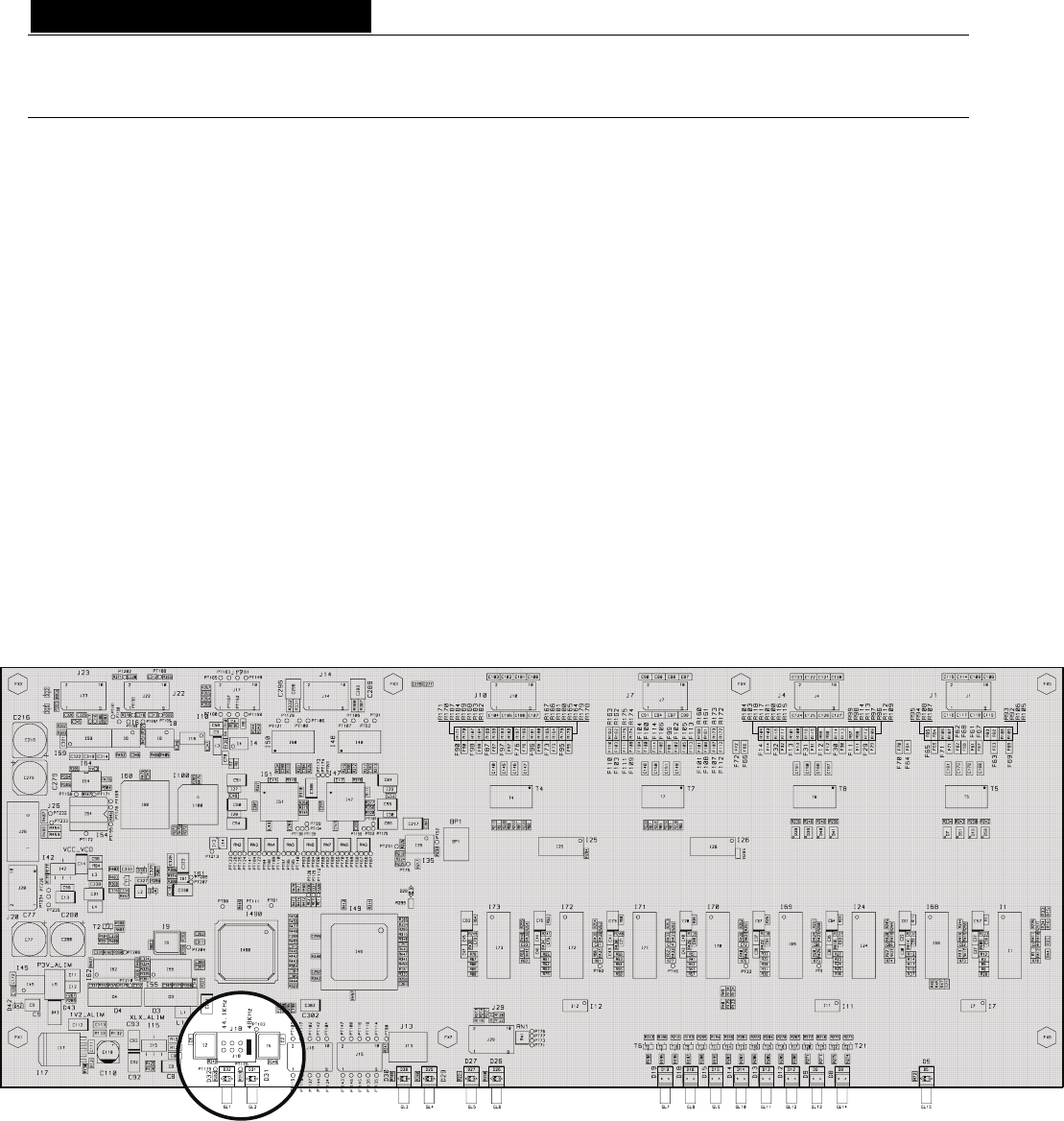
Jumper location on the main board
EtherSound ES881, ES1241 & ES16161
Ethernet Audio Bridges
15
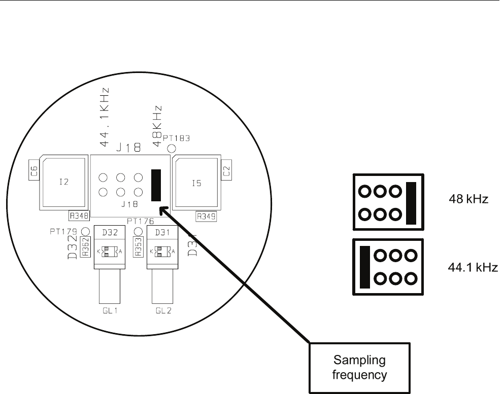
Selct sampling frequency
This jumper allows for modification of theES881, ES1241, and ES16161 sampling frequency. The default
value is preset to 48 kHz. It can be set to 44.1 kHz. Note that this setting is effective only if the ES881 is the
Primary Master of the EtherSound network, as the Primary Master is the device providing the clock for the
entire network. In case the EtherSound bridge acts as “common” Master or Slave device, the sampling
frequency is determined by the incoming EtherSound stream (synchronized on the Primary Master clock).
Modifications on devices other than the Primary Master will be ignored.
D i g i g r a m
16
APPENDIX C: GLOSSARY
AUDIO CHANNEL
An audio channel is a single mono audio signal. By extension, an audio channel is one of the 64 slots of an
EtherSound frame, i.e. a signal sampled at 48 KHz with a 24-bit resolution.
SWITCH
Device to connect two segments of a Local Area Network. Seeking greater filtering and forwarding speeds,
efforts were made to decrease the amount of time required to determine if a packet should be filtered or
forwarded (’latency’) by only examining the address information contained at the start of the Ethernet frame.
The term ‘Ethernet Switch’ now is used for multiple-port-devices, which are able to filter and forward packets
at nearly the speed of Ethernet (‘wire speed’) regardless of the technique.
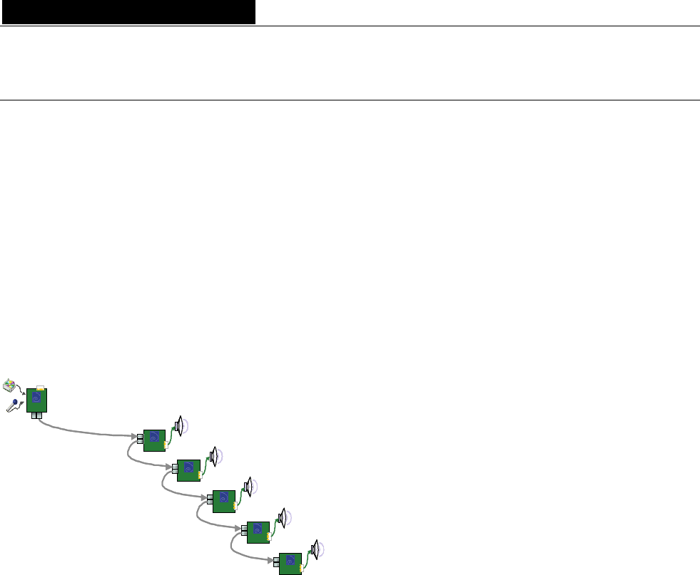
DAISY CHAIN
The daisy chain is a network topology where all devices are linked "serially".
ES
ES
ES
ES
ES
SLAVE 5
SLAVE 4
SLAVE 3
SLAVE 2
SLAVE 1
ES
PRIMARY
MASTER
ESES
ESES
ESES
ESES
ESES
SLAVE 5
SLAVE 4
SLAVE 3
SLAVE 2
SLAVE 1
ES
PRIMARY
MASTER
ES
PRIMARY
MASTER
ESES
PRIMARY
MASTER
GPIO
General Purpose Inputs Outputs. Each ES8 device has four GPIs and four GPOs. GPOs can be fully
configured to remotely control external devices. GPIs can be used to receive commands from external devices.
MASTER
A Master is a device contributing audio channels into the EtherSound network. It is located downstream from
the Primary Master.
A Master answers to the status requests and commands of the Primary Master. See also Primary Master.
PRIMARY MASTER
The first EtherSound device in the network is called the Primary Master. As well as being a source of audio for
the network, the Primary Master provides the commands and the clock for audio channel synchronization.
The Primary Master may also serve as the link between the EtherSound network and configuration software
running on an external computer, connected to its Ethernet FROM port.
EtherSound ES881, ES1241 & ES16161
Ethernet Audio Bridges
17
SLAVE
An EtherSound device that receives the EtherSound stream and restores standard audio is called a Slave.
A Slave answers to the status requests and commands of the Primary Master.
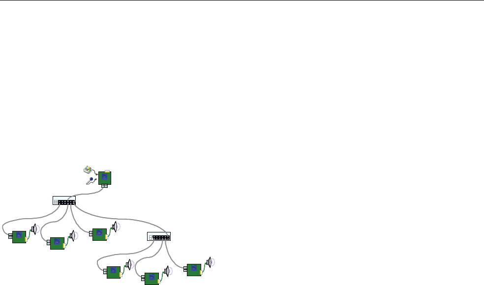
STAR
Star is a network topology where all devices are connected to a same unit (a switch in the following picture)
that is handling all the communications.
Switch 1
ES
ES
ES
Switch 2
ES
ES
ES SLAVE 5
SLAVE 4
SLAVE 3
SLAVE 2
SLAVE 1
SLAVE 6
ES
PRIMARY
MASTER
Switch 1Switch 1
ESES
ESES
ESES
Switch 2Switch 2
ESES
ESES
ESES SLAVE 5
SLAVE 4
SLAVE 3
SLAVE 2
SLAVE 1
SLAVE 6
ES
PRIMARY
MASTER
ES
PRIMARY
MASTER
ESES
PRIMARY
MASTER

Digigram
Digigram (www.digigram.com) digital audio solutions are
key to the success of public address and pro sound installations, as
well as broadcast and media production companies worldwide.We
develop innovative networked audio devices, computer sound cards,
and audio management software.
Digigram Powered solutions are installed in thousands of radio
and television stations; corporate and commercial sound
installations; and audio recording and video post-production facilities
around the globe.
Customers are served from three regional business units:
Digigram SA (Digigram Headquarters, Montbonnot, France),
Digigram Inc. (Arlington,VA USA) and Digigram Asia (Singapore).
Digigram is publicly traded on the Paris stock exchange (Code ISIN:
FR00000 35784).
www.digigram.com
Digigram SA
(Serving Europe, Africa, Middle East, Latin America)
Parc de Pré Milliet 38330 Montbonnot-FRANCE
Tel: +33 (0)4 76 52 55 01 • Fax: +33 (0)4 76 52 53 07
E-mail: sales@digigram.com
Digigram Inc.
(Serving North America)
2101 Wilson Boulevard, Suite 1004,
Arlington,VA 22201-USA
Tel: +1 703 875 9100 • Fax: +1 703 875 9161
E-mail: input@digigram.com
Digigram Asia Pte Ltd.
(Serving Asia and Australia/Oceania)
350 Orchard Road - #19-07 Shaw House Singapore
238868-SINGAPORE
Tel: +65 6291 2234 • Fax: +65 6291 3433
E-mail: info_asia@digigram.com
Networking Your Sound
Digigram, the Digigram logo, ESnet, EtherSound, and the EtherSound logo are trademarks or registered trademarks of Digigram S.A. Other trademarks are property of their respective holders. Contents copyright © November 2005 by Digigram S.A.
While every effort has been made to ensure accuracy, Digigram is not responsible for errors and omissions, and reserves the right to make improvements or changes in the products and programsdescribed without notice.