Digigram ES8MIC Ethernet Audio Distributor User Manual ES8in 8out
Digigram Ethernet Audio Distributor ES8in 8out
UserManual.wiki
>
Digigram
>
ES8MIC User Manual
User Manual
Navigation menu
Upload a User Manual
Namespaces
Wiki Guide
HTML
PDF
Info
Views
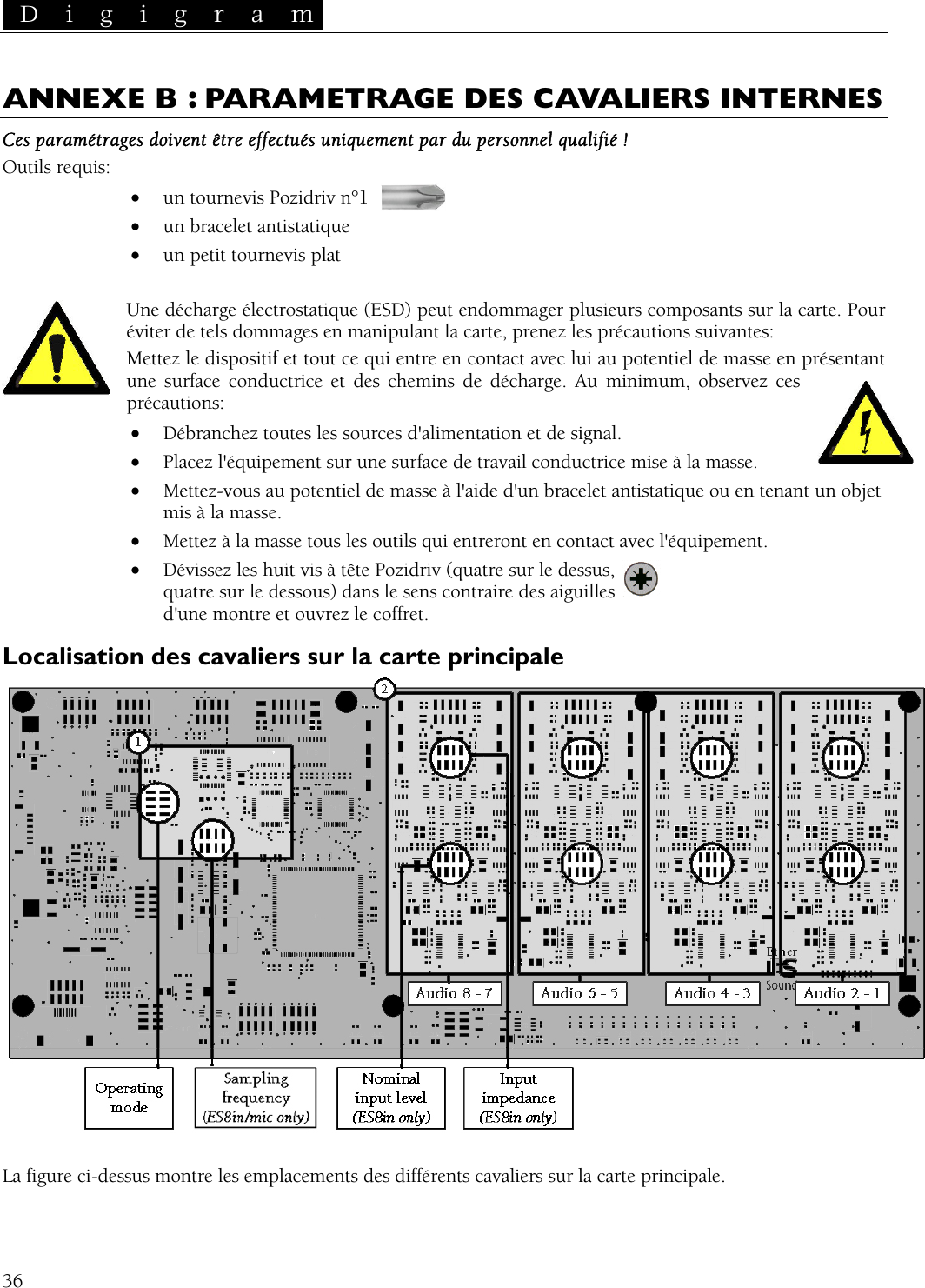
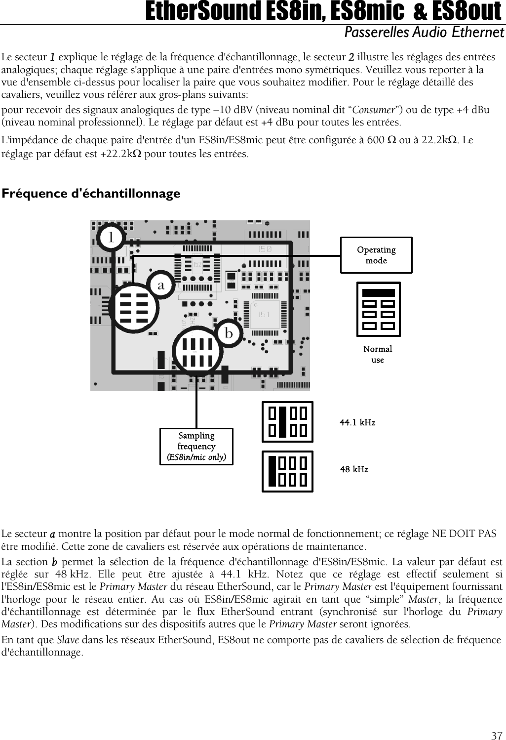
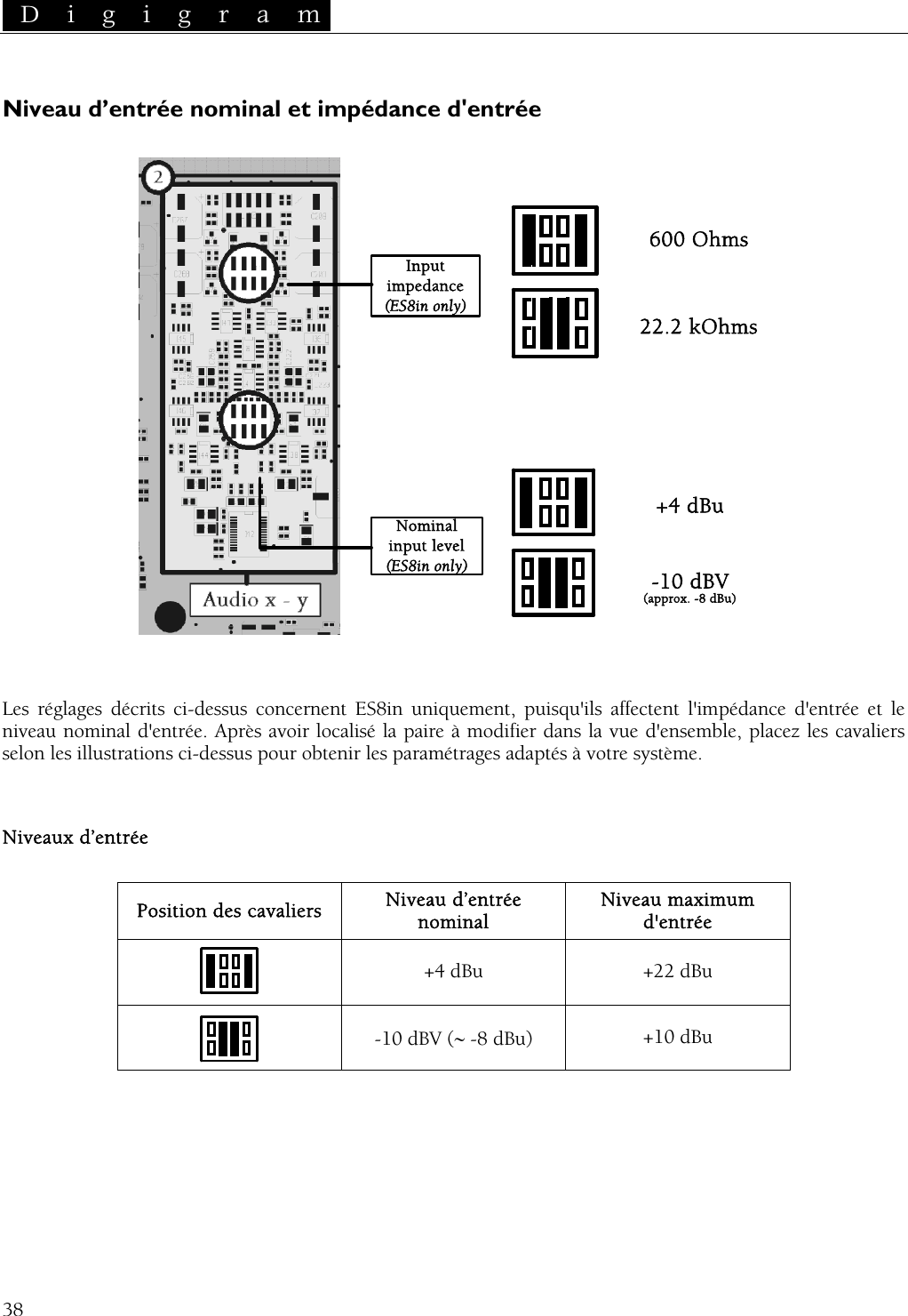
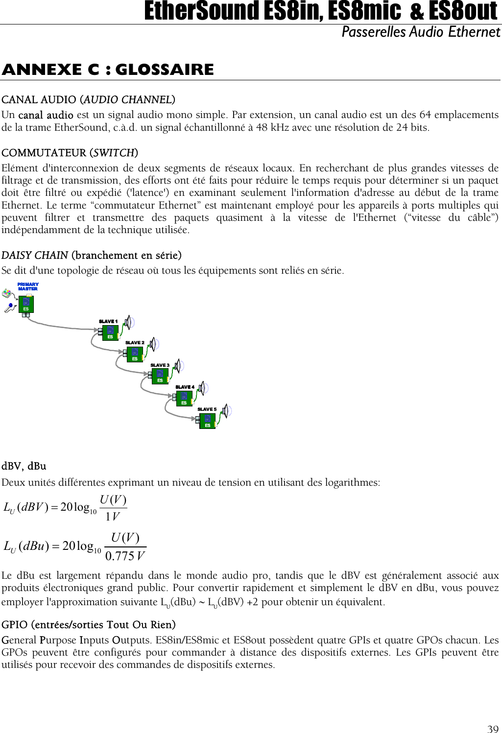
User Manual
Discussion / Help
Navigation