Digital Ally VULINK2 Digital Transmission System User Manual
Digital Ally, Inc. Digital Transmission System
UserManual.wiki
>
Digital Ally
>
VULINK2 User Manual
User Manual
Navigation menu
Upload a User Manual
Namespaces
Wiki Guide
HTML
PDF
Info
Views
User Manual
Discussion / Help
Navigation
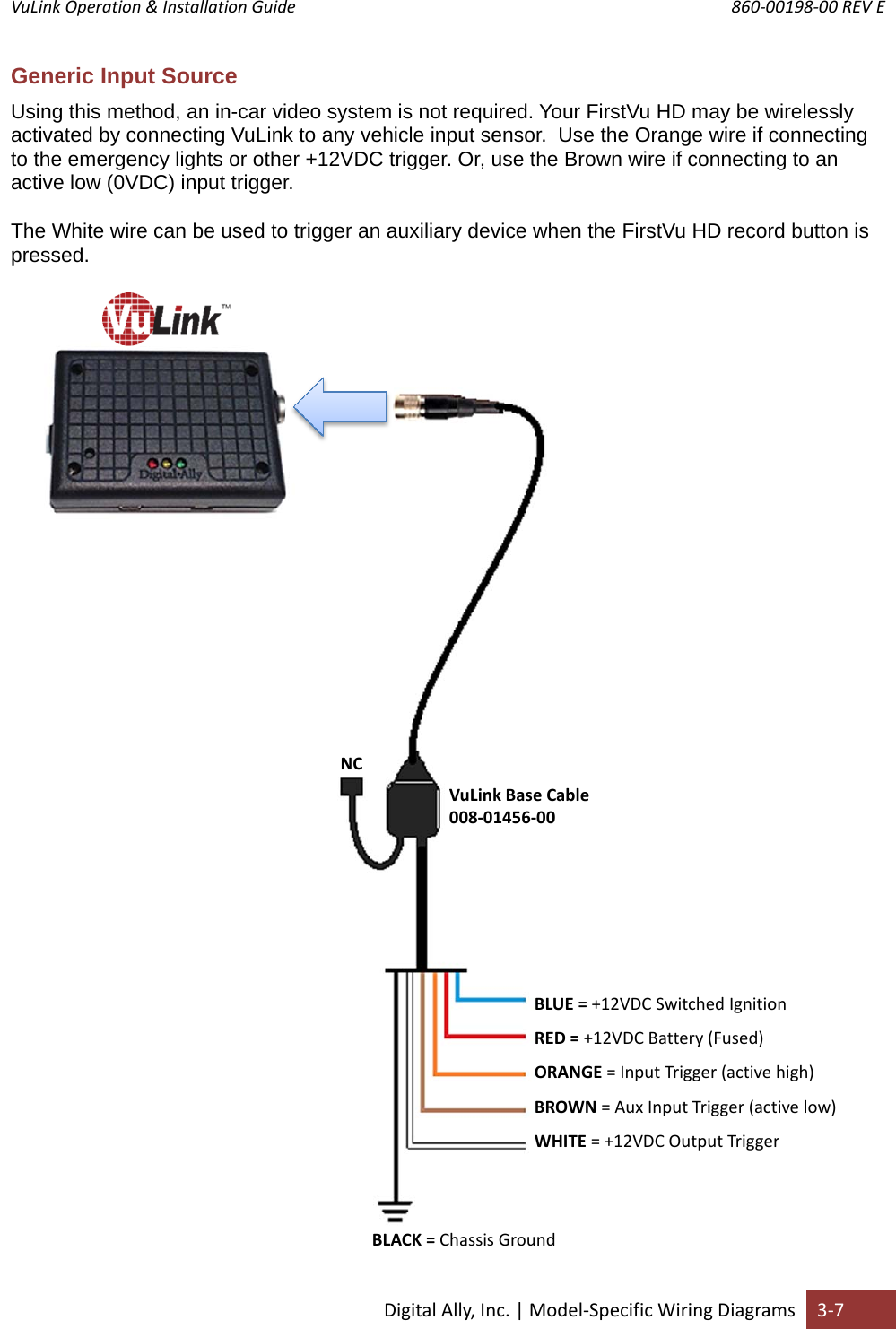
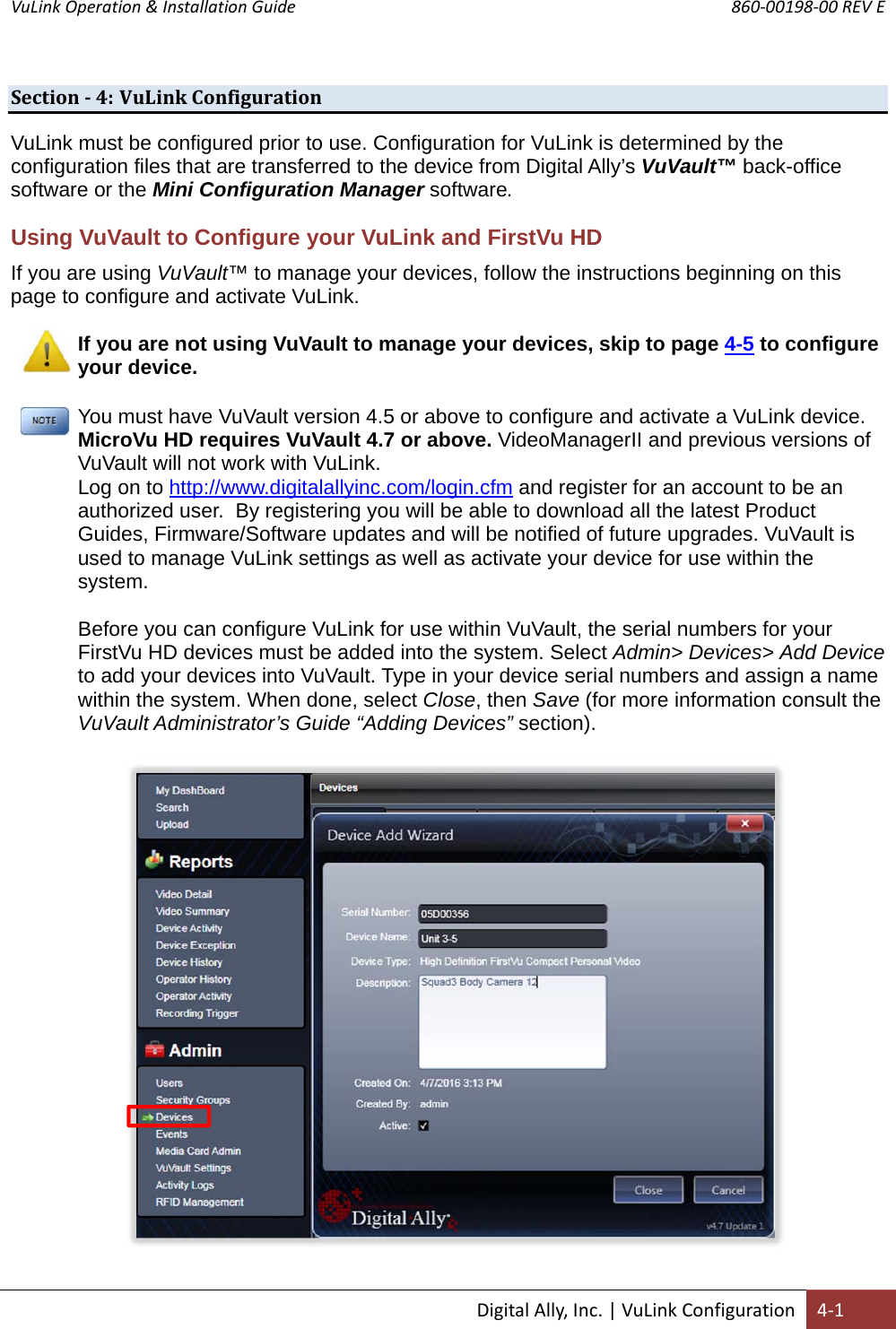
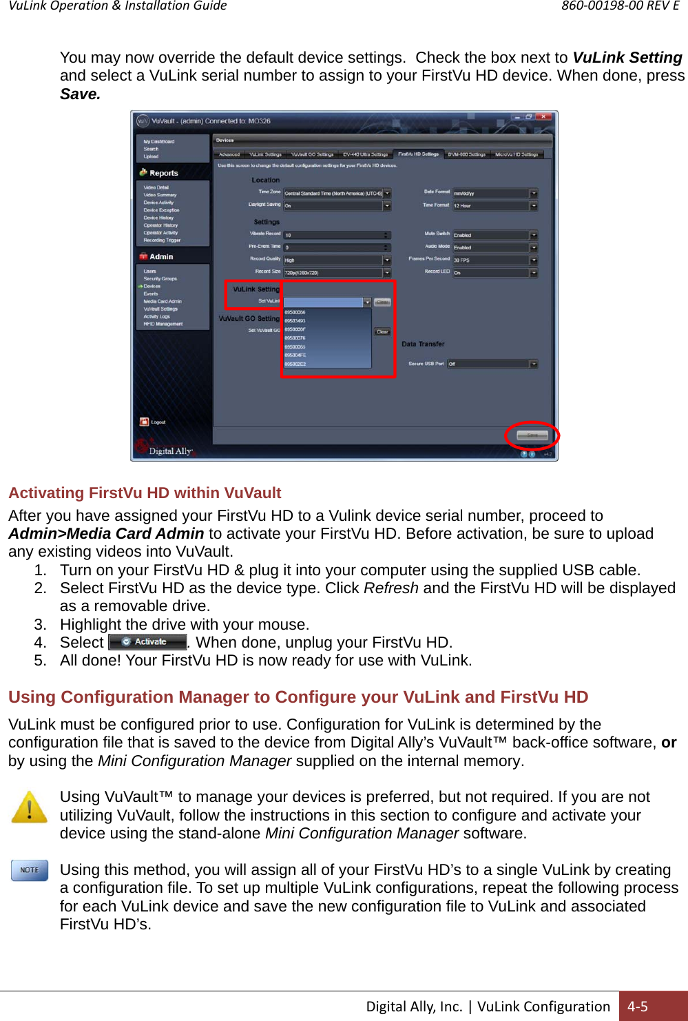
![VuLink Operation & Installation Guide 860‐00198‐00 REV E DigitalAlly,Inc.|VuLinkConfiguration4‐3Authentication Mode This parameter specifies the security authentication required by VuLink. Settings: WPAPSK, WPA2PSK [default] Encryption Type This parameter specifies the wireless encryption protocol required by VuLink. If selecting WPA2PSK as the authentication mode, choose AES as the encryption type. If selecting WPAPSK as the authentication mode, choose TKIP as the encryption type. Settings: TKIP, AES [default] Broadcast Choose whether or not to broadcast the SSID. Broadcasting allows computers with wireless cards to find the network by browsing, and may help whenever troubleshooting the system. Disabling the broadcast of the SSID prevents browsing to find the network. Settings: On, Off [default] Ignition Shutdown Timer The Ignition Shutdown Timer specifies the amount of time the VuLink remains fully powered when the vehicle ignition goes from ON to OFF. Settings: 0 to 50 minutes, 1 hr, 2 hrs, 4 hrs, 8 hrs, 12 hrs, 24 hrs, and Unlimited [default = 1 hour] DuringtheIgnitionShutdownTime:1. If configured to 0 minutes; the Ignition Shutdown Timer is disabled, and VuLink will shut down when ignition is turned off. 2. If the FirstVu HD is not recording, all LED Indicators will turn off, but VuLink will remain fully powered until the timer expires. 3. During an active record, the FirstVu HD will continue recording and the system status indicators will operate normally until the recording ends. 4. If the Ignition Shutdown Timer has not expired, the unit will allow an event record start from any of the available Event Record Start Triggers. If a recording begins, the system indicators will operate normally until the recording ends. 5. Once the Ignition Shutdown Timer expires, the system will stop an active recording. 6. If the vehicle ignition is turned ON before the timer expires, the Ignition Shutdown Timer is cancelled and will start over again when the ignition is turned off. Activating VuLink After your desired settings have been entered, attach VuLink to your computer using the supplied USB cable. Your computer will recognize VuLink as a removable disk drive. Press the button. You’ll then be prompted to choose a location to save the configuration file named “deviceconfig”. Save this configuration file onto your VuLink device. After the file has been transferred to the VuLink, it may be unplugged from your computer.](https://usermanual.wiki/Digital-Ally/VULINK2/User-Guide-3261350-Page-17.png)
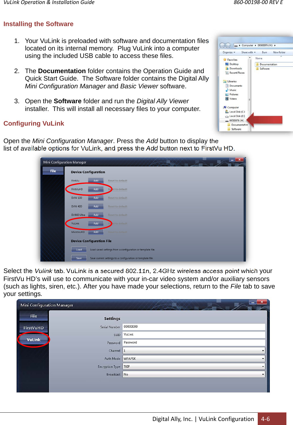
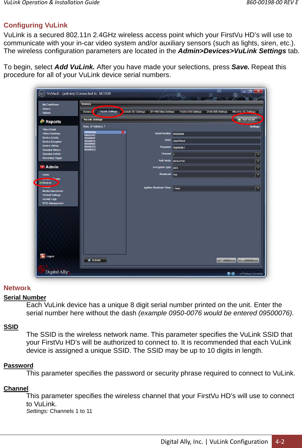
![VuLink Operation & Installation Guide 860‐00198‐00 REV E DigitalAlly,Inc.|VuLinkConfiguration4‐7Settings Serial Number Your VuLink device has a unique 8 digit serial number printed on the unit. Enter the serial number here without the dash (example 0950-0076 would be entered 09500076). SSID The SSID is the wireless network name. This parameter specifies the VuLink SSID that your FirstVu HD’s will be authorized to connect to. The SSID may be up to 10 digits in length. Password This parameter specifies the password or security phrase required to connect to VuLink. Channel This parameter specifies the wireless channel that your FirstVu HD’s will use to connect to VuLink. Settings: 1 to 11, 1 [default] Authentication Mode This parameter specifies the security authentication required by VuLink. Settings: WPAPSK, WPA2PSK Encryption Type This parameter specifies the wireless encryption protocol required by VuLink. If selecting WPA2PSK (preferred) as the authentication mode, choose AES as the encryption type. If selecting WPAPSK as the authentication mode, choose TKIP as the encryption type. Settings: TKIP, AES Broadcast Choose whether or not to broadcast the SSID. Broadcasting allows computers with wireless cards to find the network by browsing. Disabling the broadcast of the SSID prevents browsing to find the network. Settings: On, Off [default] Ignition Shutdown Timer The Ignition Shutdown Timer specifies the amount of time VuLink remains fully powered when the vehicle ignition goes from ON to OFF. Settings: 0 to 50 minutes, 1 hr, 2 hrs, 4 hrs, 8 hrs, 12 hrs, 24 hrs, and Unlimited [default = 1 hour] DuringtheIgnitionShutdownTime:7. If configured to 0 minutes; the Ignition Shutdown Timer is disabled, and VuLink will shut down when ignition is turned off. 8. If the FirstVu HD is not recording, all LED Indicators will turn off, but VuLink will remain fully powered until the timer expires. 9. During an active record, the FirstVu HD will continue recording and the system status indicators will operate normally until the recording ends. 10. If the Ignition Shutdown Timer has not expired, the unit will allow an event record start from any of the available Event Record Start Triggers. If a recording begins, the system indicators will operate normally until the recording ends. 11. Once the Ignition Shutdown Timer expires, the system will stop an active recording. 12. If the vehicle ignition is turned ON before the timer expires, the Ignition Shutdown Timer is cancelled and will start over again when the ignition is turned off.](https://usermanual.wiki/Digital-Ally/VULINK2/User-Guide-3261350-Page-21.png)