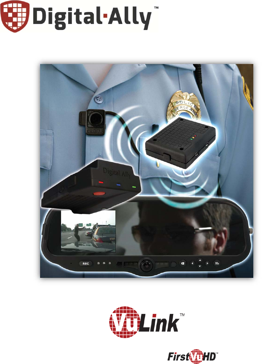
Digital Ally VULINK2 Digital Transmission System User Manual
Digital Ally, Inc. Digital Transmission System
User Manual
Copyright©2014‐2016,DigitalAlly,Inc.AllRightsReserved.Thispublicationmaynotbereproduced,storedinaretrieval
system,ortransmittedinwholeorpartinanyformorbyanymeanselectronic,mechanical,recording,photocopying,orinany
othermannerwithoutthepriorwrittenapprovalofDigitalAlly,Inc.
86
0
‐00198‐00 Rev E
In‐CarVideoLinkfor
OperationandInstallationGuide
VuLink Operation & Installation Guide 860‐00198‐00 REV E
i
TableofContents
SECTION - 1: BEFORE YOU BEGIN ...................................................................................................................1-1
OVERVIEW OF FEATURES ......................................................................................................................................1-1
INSTALLATION TOOLS NEEDED ............................................................................................................................1-1
CAUTIONS AND NOTES .........................................................................................................................................1-1
SPECIFICATIONS ...................................................................................................................................................1-1
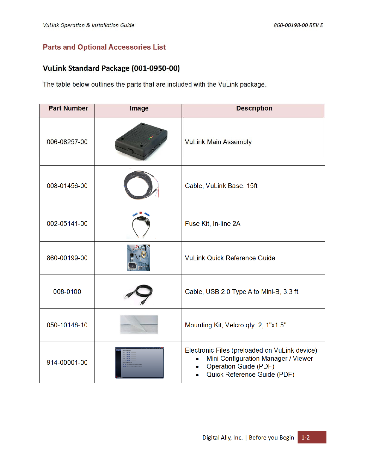
PARTS AND OPTIONAL ACCESSORIES LIST ............................................................................................................1-2
SECTION - 2: INSTALLATION INSTRUCTIONS .............................................................................................2-1
STEP 1: PREPARE THE VEHICLE ............................................................................................................................2-1
STEP 2: POWER, IGNITION, AND GROUND CONNECTIONS .....................................................................................2-2
STEP 3: VULINK TRIGGER CONNECTIONS ............................................................................................................2-2
STEP 4: VULINK INSTALLATION ...........................................................................................................................2-3
SECTION - 3: MODEL-SPECIFIC WIRING DIAGRAMS ................................................................................3-1
DVM-100 / DVM-400 .........................................................................................................................................3-1
DVM-500PLUS / DVM-750 .................................................................................................................................3-2
DVM-800 / DVM-LIVE ......................................................................................................................................3-3
DV-440ULTRA .....................................................................................................................................................3-4
DVM-250PLUS OR DVM250 (WITH INTERFACE BOX) ..........................................................................................3-5
MICROVU HD ......................................................................................................................................................3-6
GENERIC INPUT SOURCE ......................................................................................................................................3-7
SECTION - 4: VULINK CONFIGURATION .......................................................................................................4-1
USING VUVAULT TO CONFIGURE YOUR VULINK AND FIRSTVU HD ....................................................................4-1
Configuring VuLink ......................................................................................................................................4-2
Activating VuLink .........................................................................................................................................4-3
Assigning Your FirstVu HD to a VuLink Device ...........................................................................................4-4
Activating FirstVu HD within VuVault ..........................................................................................................4-5
USING CONFIGURATION MANAGER TO CONFIGURE YOUR VULINK AND FIRSTVU HD .........................................4-5
Installing the Software ..................................................................................................................................4-6
Configuring VuLink ......................................................................................................................................4-6
Saving your Settings .....................................................................................................................................4-8
DVM-800, DVM-250, AND DVM-250PLUS DEVICE CONFIGURATION ................................................................4-9
SECTION - 5: OPERATION ...................................................................................................................................5-1
POWER CONTROL .................................................................................................................................................5-1
TESTING THE SYSTEM ..........................................................................................................................................5-1
COVERT MODE .....................................................................................................................................................5-1
VULINK™ LED STATUS INDICATORS ...................................................................................................................5-2
FIRSTVU HD™ LED STATUS INDICATOR .............................................................................................................5-2
SECTION - 6: SUPPORT ........................................................................................................................................6-1
FIRMWARE UPDATES ............................................................................................................................................6-1
PERFORMING A RESET ..........................................................................................................................................6-1
TROUBLESHOOTING .............................................................................................................................................6-2
PRODUCT REPAIR .................................................................................................................................................6-2
SECTION - 7: WARRANTY INFORMATION .....................................................................................................7-1
SECTION - 8: CONTACT INFORMATION .........................................................................................................8-1
SECTION - 9: REGULATORY ...............................................................................................................................9-1

VuLink Operation & Installation Guide 860‐00198‐00 REV E
DigitalAlly,Inc.|BeforeyouBegin1‐1
Section‐1: BeforeyouBegin
Overview of Features
Automatically start recordings on your Firstvu HD™ using the same triggers as vehicle
video systems, regardless of whether the unit is mounted or worn.
Simultaneously start recordings with your vehicle video system, whether started
manually on either system or automatically triggered.
Eliminate distraction and the need to continuously record or remember to press record.
Installation Tools Needed
Wire Strippers
Tools to remove vehicle trim
Wire Crimpers
Digital Volt Meter
Cautions and Notes
Please read and follow the instructions and precautions in this installation guide when installing
VuLink.
For assistance, a qualified installation technician or mechanic should be consulted.
To prevent electrical shorts or breakage in the wiring and cabling, do not allow wiring and
cabling to be pinched behind trim pieces, panels, or other physical objects.
Do not run wires or cables in areas where they may become damaged by heat from the
engine or the exhaust system.
Do not install any wiring in the deployment path of any air bags.
When installing the cables or making wire connections, it is recommended you leave a little
‘slack’ in the cable connections to allow for service loops so the connections do not get
pulled or accidentally disconnected.
We recommend at least 2 feet of distance between VuLink and that of other systems which
may carry a signal for transmit and/or receive.
Specifications
OPERATINGVOLTAGE8‐30VDC
CURRENTDRAW 250mAMaximum
MAXTRANSMITPOWER10dBm
TRANSMITRANGE50fttypical
WEIGHT 55.4g(0.12lbs.)
OPERATINGTEMPERATURE‐30°to+60
°
C
STORAGETEMPERATURE‐40°to+80° C
DIMENSIONS23mm(0.9in.)(D)x91mm(3.6in.)(W)x61mm(2.4in.)(H)
VuLink Operation & Installation Guide 860‐00198‐00 REV E
DigitalAlly,Inc.|BeforeyouBegin1‐2
VuLink Operation & Installation Guide 860‐00198‐00 REV E
DigitalAlly,Inc.|InstallationInstructions2‐1
Section‐2: InstallationInstructions
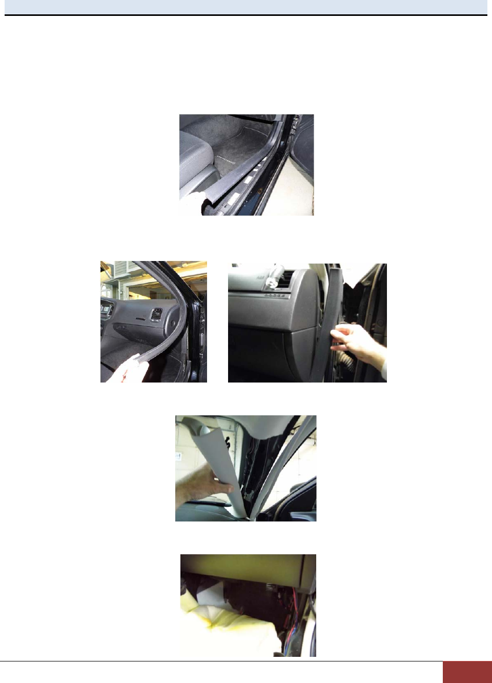
Step 1: Prepare the vehicle
1. VuLink is typically mounted on the windshield near the roofline area. Plan a safe path for
the base cable from the windshield area to your power source and remove necessary
body trim pieces. Remove front passenger side threshold.
2. Pull the door seal away.
3. Remove the passenger side front interior A-pillar cover.
4. Remove the passenger side kick panel & pull back the carpet to expose the vehicle
chassis.
VuLink Operation & Installation Guide 860‐00198‐00 REV E
DigitalAlly,Inc.|InstallationInstructions2‐2
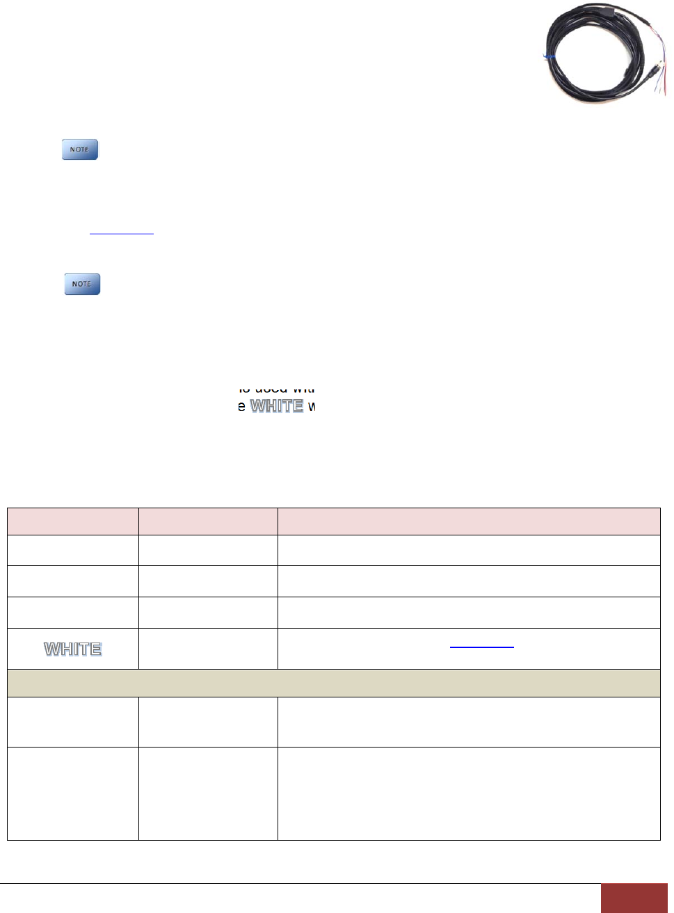
Step 2: Power, Ignition, and Ground Connections
Remove 6 to 7 inches of the outer jacket at the bare end of the base cable.
The Red wire of the base cable should be connected to the vehicle constant
+12VDC through the supplied fuse kit. Connect the Blue wire to the ignition
switch where +12VDC is only present when the vehicle ignition key is in the
ON position. The Black wire connects directly to the vehicle’s chassis.
Secure all cables and in-line fuse housing using Velcro or standard tie
wraps as required. Consult Figure 3-2 below.
To ensure stable operation, power and ground should be directly connected to
the vehicle battery.
Step 3: VuLink Trigger Connections
Consult the Section 3 diagrams for your specific video system or generic input trigger
connection. VuLink has two input trigger options for you to choose from.
If installing VuLink to be used only with MicroVu HD, do not connect the
VuLink trigger wires. The MicroVu HD triggers are used instead.
The Orange wire is an active high trigger input which is tied to a switched +12VDC source when
the desired trigger is active. This wire is usually tied to the emergency light bar controller output.
The Brown wire is an active low trigger input which is tied to a switched 0VDC source when the
desired trigger is active. This wire is used with the DVM-800 and DVM-250Plus and is typically
tied to the IF box output alarm. The wire is the VuLink output trigger. When you press
the record button on your FirstVu HD, VuLink will apply a 1 second +12VDC signal on this wire.
Make the connections as shown in the table below:
Wire Color Function Connection
RED
Battery Connect to +12VDC battery terminal (Use Fuse kit)
BLACK
Ground Connect to vehicle chassis ground
BLUE
Ignition Connect to +12VDC switched ignition
Trigger OUT Consult the diagrams in Section 4 for your installation.
This wire connects to the video system input sensor.
Choose one of the two input trigger options below
BROWN
Trigger IN
Active LOW For the DVM-250, connect to BROWN wire of I/F box.
Optional GND (active LOW) trigger.
ORANGE
Trigger IN
Active HIGH
For DVM-100/400/250Plus/440Ultra/500Plus/750,
connect to +12VDC when the emergency light bar is
active (or any other desired +12VDC trigger).
For DVM-800 connect to DWM Wireless Microphone
Trigger Output (Green).
Figure 3-2: VuLink Base Cable Connections
VuLink Operation & Installation Guide 860‐00198‐00 REV E
DigitalAlly,Inc.|InstallationInstructions2‐3
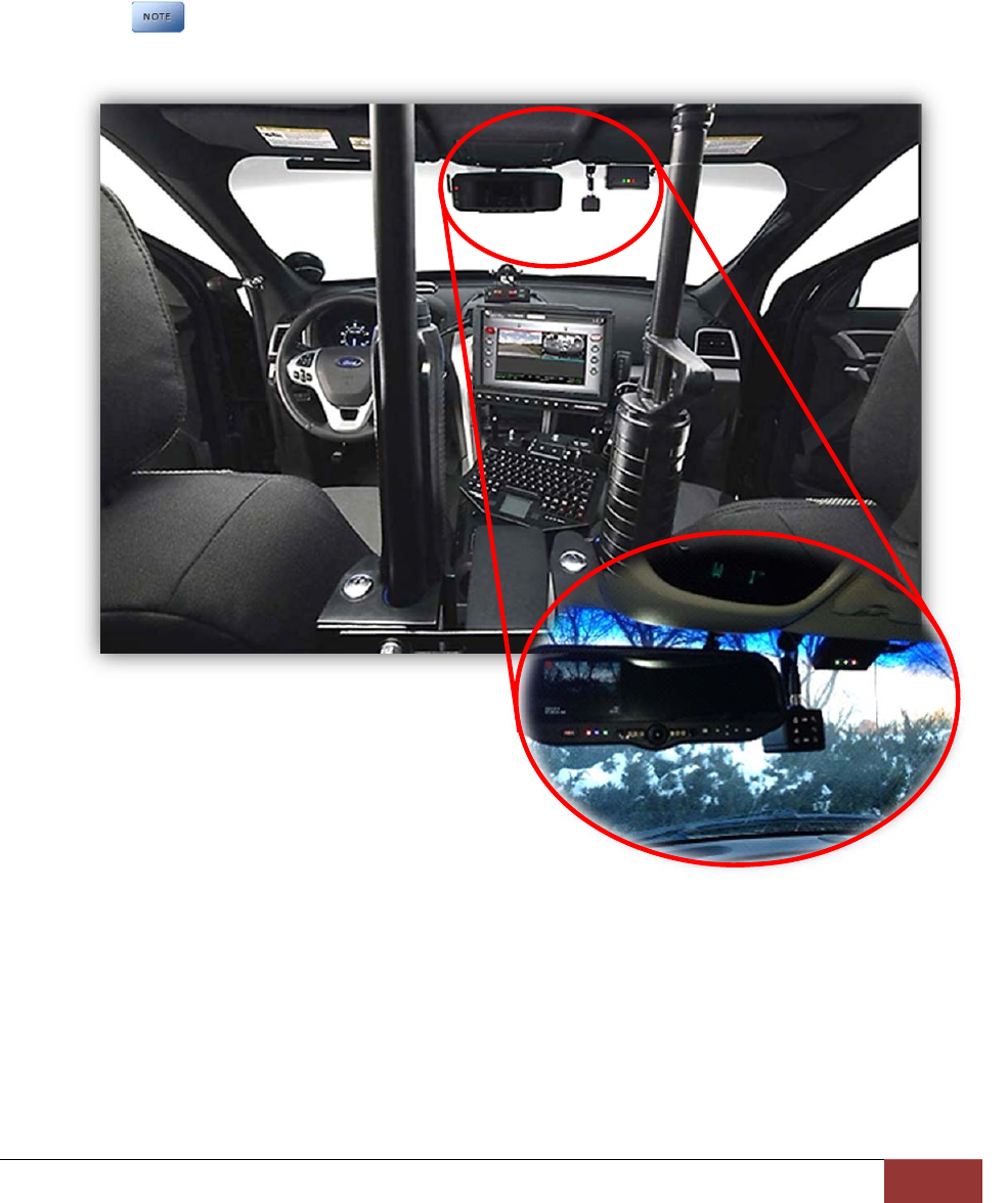
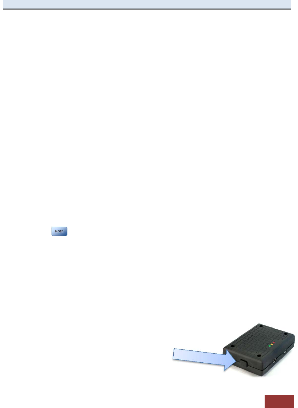
Step 4: VuLink Installation
Plug the base cable into the connector on the side of VuLink. Prep the windshield glass with
alcohol to remove any dirt or debris. Using the included Velcro kit, attach VuLink to an
unobstructed location on the windshield below the roofline. To avoid possible interference
from other vehicle equipment, do not mount VuLink near other vehicle antennas.
The GREEN power LED will be illuminated as long as it is receiving battery power,
regardless of the ignition switch position.
VuLink Operation & Installation Guide 860‐00198‐00 REV E
DigitalAlly,Inc.|Model‐SpecificWiringDiagrams3‐1
Section‐3: Model‐SpecificWiringDiagrams
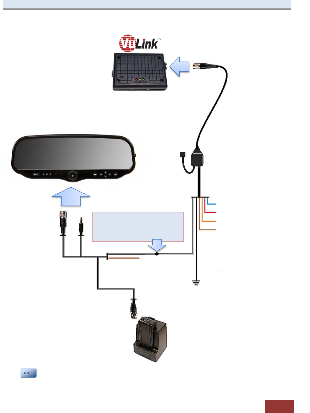
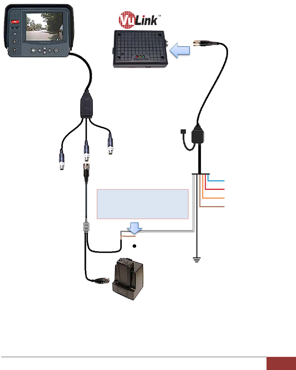
DVM-100 / DVM-400
DVM
VuLinkBaseCable
008‐01456‐00
BLACK=ChassisGround
DWM Wireless
Microphone
Cable
NC
BLUE=+12VDCSwitchedIgnition
RED=+12VDCBattery(Fused)
ORANGE=EmergencyLightInput
BROWN=Notused
ConnectWHITEwirefrom
VuLinkBaseCabletoWHITE
wireofDWMsensorcable
WHITE
The DVM‐100/400 models do not have an output alarm sensor. Therefore, VuLink cannot
trigger the FirstVu HD to automatically record if the RECORD BUTTON is pressed on the
front of the DVM, or if the WIRELESS MICROPHONE is used to initiate a recorded event.
VuLink Operation & Installation Guide 860‐00198‐00 REV E
DigitalAlly,Inc.|Model‐SpecificWiringDiagrams3‐2
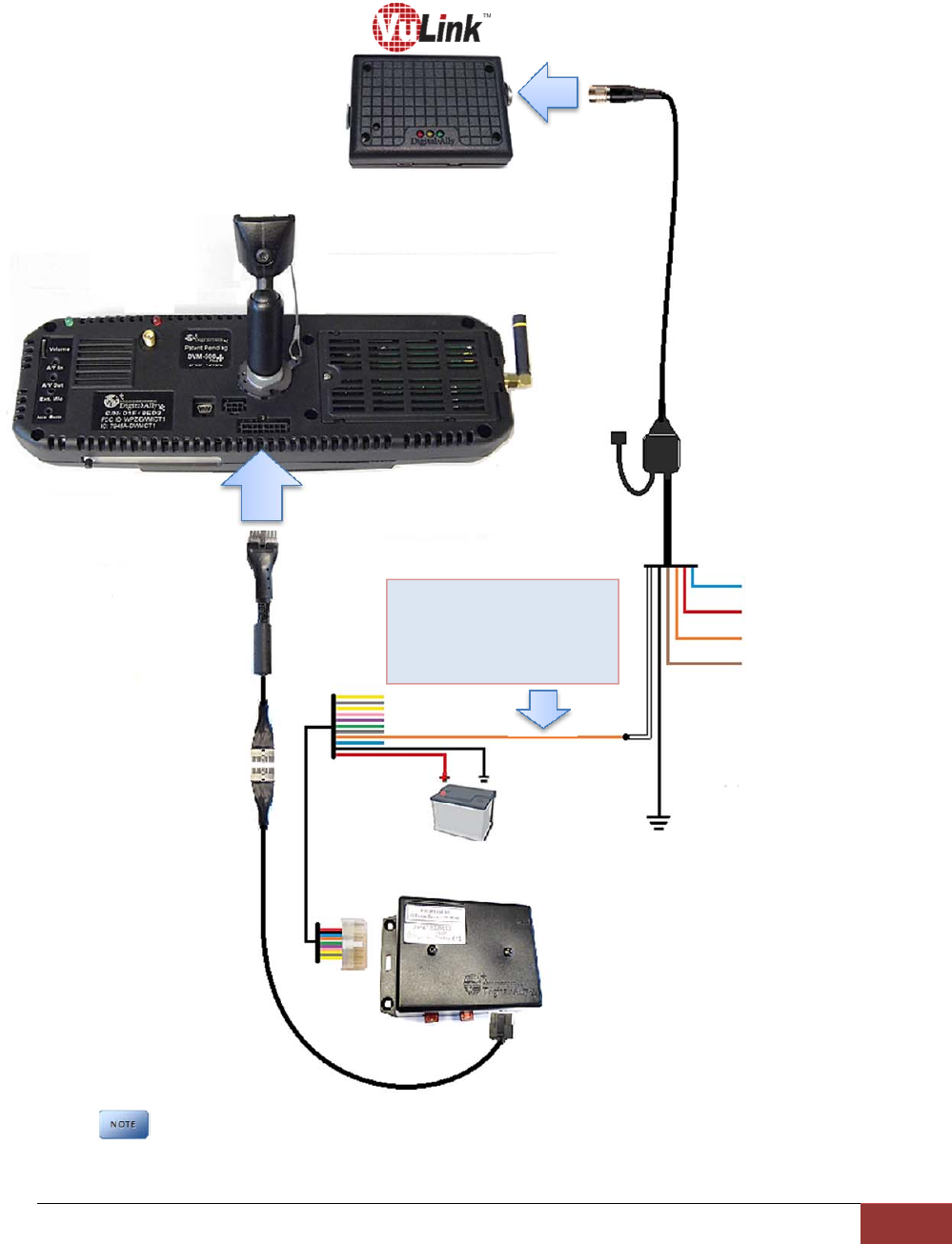
DVM-500Plus / DVM-750
BLUE=+12VDCSwitchedIgnition
RED=+12VDCBattery(Fused)
ORANGE=EmergencyLightInput
BROWN=Notused
BLACK=ChassisGround
DVM
VuLinkBaseCable
008‐01456‐00
I/FBox
NC
ConnectWHITEwire
fromVuLinkBaseCable
toORANGEwireofI/F
BOXin
p
utsensorcable
WHITE
The DVM 500plus/750 models do not have an output alarm sensor. Therefore, VuLink
cannot trigger the FirstVu HD to automatically record if the RECORD BUTTON is pressed on
the front of the DVM, or if the WIRELESS MICROPHONE is used to initiate a recorded event.
VuLink Operation & Installation Guide 860‐00198‐00 REV E
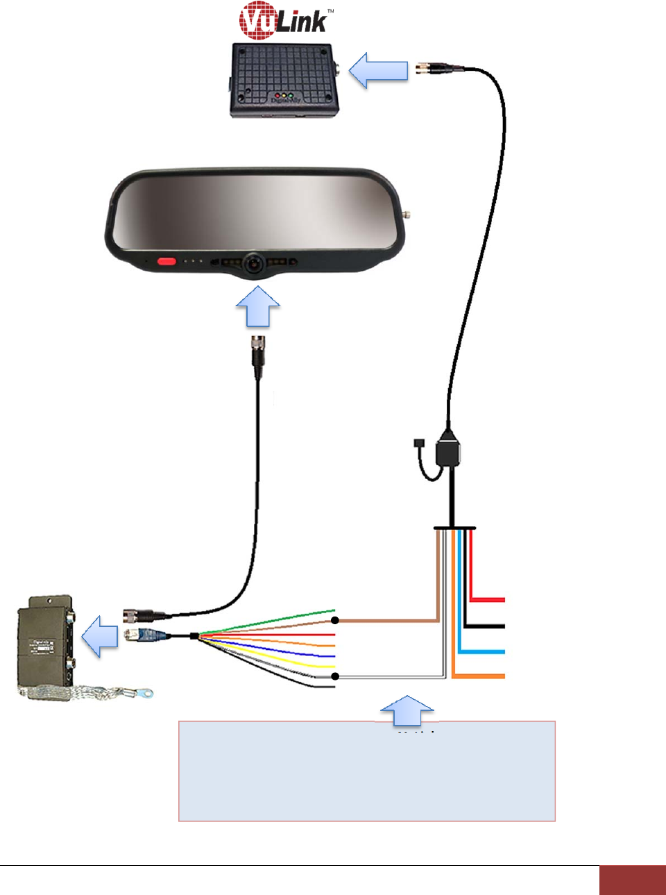
DigitalAlly,Inc.|Model‐SpecificWiringDiagrams3‐3
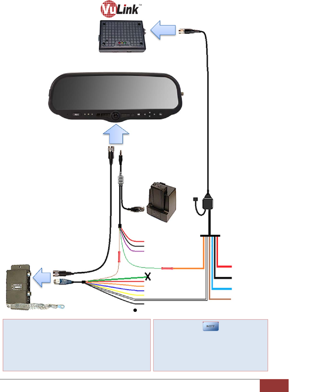
DVM-800 / DVM-LiVE
I/FBox
VuLinkBaseCable
008‐01456‐00
RED=+12VDCBattery (Fused)
BLACK=Ground
BLUE=+12VDCSwitchedIgn
BROWN=OptionalGND
InputTrigger
DVM‐800
NC
ORANGE
1.ConnectORANGEwirefromVuLinkBaseCableto
GREENwireoftheDWMWirelessMicrophone
(microphonetriggerout)
2.ConnectWHITEwirefromVuLinkBaseCableto
WHITEwireofI/Fboxinputsensorcable(Sensor5)
I/FBoxInput
SensorCable
WHITE
‐‐‐DONOTCONNECT
THISGREENWIRE
IfaddingVuLinktoanexistingDVM‐800
Installation,cuttheGREENwirecoming
fromtheI/FBoxInputSensorCable
beforeconnectingtheDWMGREENwire
totheVuLinkORANGEwire.
GREEN
DWM
Wireless
Microphone
VuLink Operation & Installation Guide 860‐00198‐00 REV E
DigitalAlly,Inc.|Model‐SpecificWiringDiagrams3‐4
DV-440Ultra
BLUE=+12VDCSwitchedIgnition
RED=+12VDCBattery(Fused)
ORANGE=EmergencyLightInput
BROWN=Notused
VuLinkBaseCable
008‐01456‐00
DWM
Wireless
Microphone
Cable
9pin
NC
BLACK=ChassisGround
DV‐440Ultra
ConnectWHITEwirefrom
VuLinkBaseCabletoWHITE
wireofDWMsensorcable
WHITE
The DV‐440Ultra does not have an output alarm sensor. Therefore, VuLink cannot trigger
the FirstVu HD to automatically record if the RECORD BUTTON is pressed on the front of the
unit, or if the WIRELESS MICROPHONE is used to initiate a recorded event.
VuLink Operation & Installation Guide 860‐00198‐00 REV E
DigitalAlly,Inc.|Model‐SpecificWiringDiagrams3‐5
DVM-250Plus or DVM250 (with interface box)
RED=+12VDCBattery (Fused)
BLACK=ChassisGround
BLUE=+12VDCSw.Ignition
ORANGE=Optional+12VDC
inputtrigger
VuLinkBaseCable
008‐01456‐00
DVM
I/FBox
1. ConnectBROWNwirefromVuLinkBaseCableto
BROWNwireofI/Fboxinputsensorcable(output
alarm)
2. ConnectWHITEwirefromVuLinkBaseCableto
WHITEwireofI/Fboxinputsensorcable(Sensor5)
NC
BROWN
WHITE
I/FBoxInput
SensorCable
VuLink Operation & Installation Guide 860‐00198‐00 REV E
DigitalAlly,Inc.|Model‐SpecificWiringDiagrams3‐6
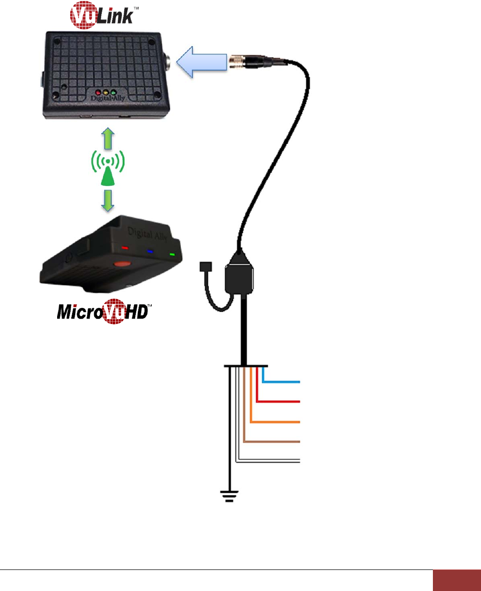
MicroVu HD
When using VuLink with a MicroVu HD, the VuLink is only wired to the Vehicle Power, Ground,
and Ignition. The MicroVu HD provides all event triggers to VuLink based on its own sensor
input connections. Triggering between the MicroVu HD and the FirstVu HD is provided through
wireless communication with VuLink.
BLUE=+12VDCSwitchedIgnition
RED=+12VDCBattery(Fused)
ORANGE=NotUsed
BROWN=NotUsed
WHITE=NotUsed
VuLinkBaseCable
008‐01456‐00
NC
BLACK=ChassisGround
TheVuLinkand
MicroVuHD
communicate
wirelesslywith
eachother.No
wiredconnection
ismade.
VuLink Operation & Installation Guide 860‐00198‐00 REV E
DigitalAlly,Inc.|Model‐SpecificWiringDiagrams3‐7
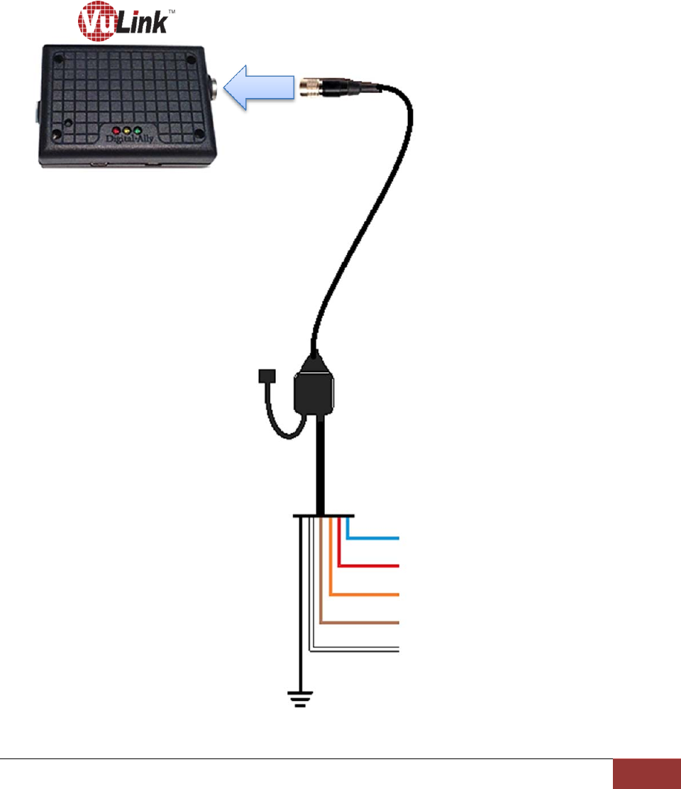
Generic Input Source
Using this method, an in-car video system is not required. Your FirstVu HD may be wirelessly
activated by connecting VuLink to any vehicle input sensor. Use the Orange wire if connecting
to the emergency lights or other +12VDC trigger. Or, use the Brown wire if connecting to an
active low (0VDC) input trigger.
The White wire can be used to trigger an auxiliary device when the FirstVu HD record button is
pressed.
BLUE=+12VDCSwitchedIgnition
RED=+12VDCBattery(Fused)
ORANGE=InputTrigger(activehigh)
BROWN=AuxInputTrigger(activelow)
WHITE=+12VDCOutputTrigger
VuLinkBaseCable
008‐01456‐00
NC
BLACK=ChassisGround
VuLink Operation & Installation Guide 860‐00198‐00 REV E
DigitalAlly,Inc.|VuLinkConfiguration4‐1
Section‐4: VuLinkConfiguration
VuLink must be configured prior to use. Configuration for VuLink is determined by the
configuration files that are transferred to the device from Digital Ally’s VuVault™ back-office
software or the Mini Configuration Manager software.
Using VuVault to Configure your VuLink and FirstVu HD
If you are using VuVault™ to manage your devices, follow the instructions beginning on this
page to configure and activate VuLink.
If you are not using VuVault to manage your devices, skip to page 4-5 to configure
your device.
You must have VuVault version 4.5 or above to configure and activate a VuLink device.
MicroVu HD requires VuVault 4.7 or above. VideoManagerII and previous versions of
VuVault will not work with VuLink.
Log on to http://www.digitalallyinc.com/login.cfm and register for an account to be an
authorized user. By registering you will be able to download all the latest Product
Guides, Firmware/Software updates and will be notified of future upgrades. VuVault is
used to manage VuLink settings as well as activate your device for use within the
system.
Before you can configure VuLink for use within VuVault, the serial numbers for your
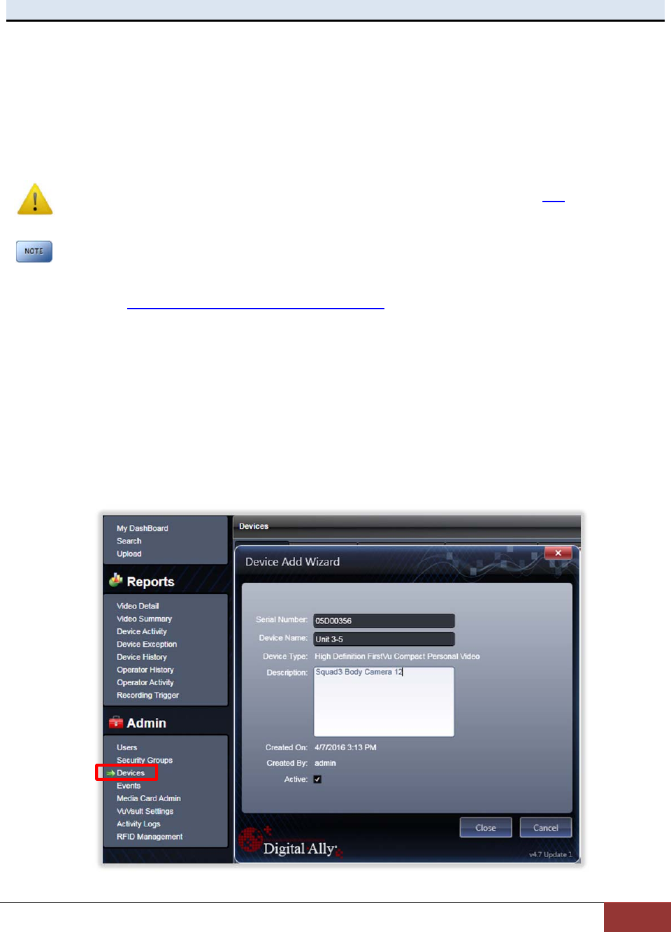
FirstVu HD devices must be added into the system. Select Admin> Devices> Add Device
to add your devices into VuVault. Type in your device serial numbers and assign a name
within the system. When done, select Close, then Save (for more information consult the
VuVault Administrator’s Guide “Adding Devices” section).
VuLink Operation & Installation Guide 860‐00198‐00 REV E
DigitalAlly,Inc.|VuLinkConfiguration4‐2
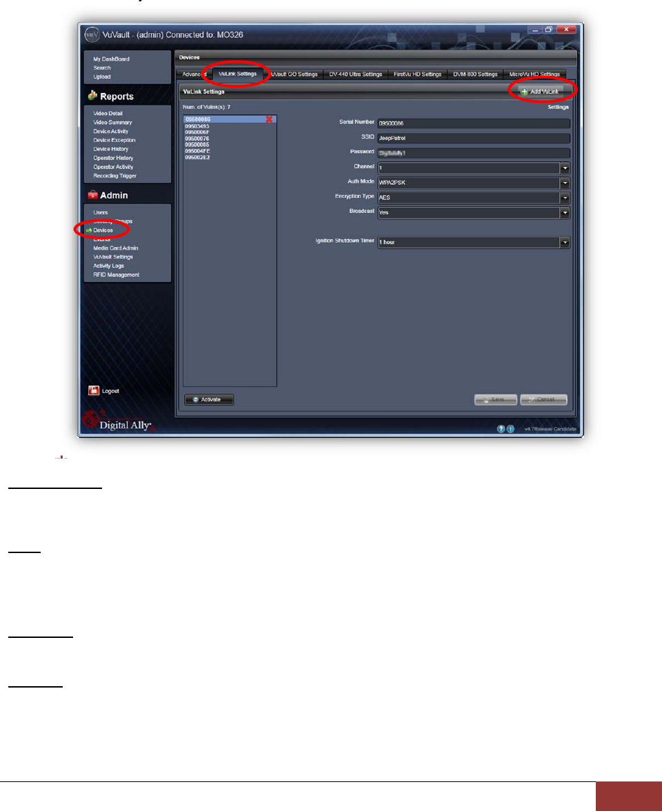
Configuring VuLink
VuLink is a secured 802.11n 2.4GHz wireless access point which your FirstVu HD’s will use to
communicate with your in-car video system and/or auxiliary sensors (such as lights, siren, etc.).
The wireless configuration parameters are located in the Admin>Devices>VuLink Settings tab.
To begin, select Add VuLink. After you have made your selections, press Save.Repeat this
procedure for all of your VuLink device serial numbers.
Network
Serial Number
Each VuLink device has a unique 8 digit serial number printed on the unit. Enter the
serial number here without the dash (example 0950-0076 would be entered 09500076).
SSID
The SSID is the wireless network name. This parameter specifies the VuLink SSID that
your FirstVu HD’s will be authorized to connect to. It is recommended that each VuLink
device is assigned a unique SSID. The SSID may be up to 10 digits in length.
Password
This parameter specifies the password or security phrase required to connect to VuLink.
Channel
This parameter specifies the wireless channel that your FirstVu HD’s will use to connect
to VuLink.
Settings: Channels 1 to 11
VuLink Operation & Installation Guide 860‐00198‐00 REV E
DigitalAlly,Inc.|VuLinkConfiguration4‐3
Authentication Mode
This parameter specifies the security authentication required by VuLink.
Settings: WPAPSK, WPA2PSK [default]
Encryption Type
This parameter specifies the wireless encryption protocol required by VuLink. If selecting
WPA2PSK as the authentication mode, choose AES as the encryption type. If selecting
WPAPSK as the authentication mode, choose TKIP as the encryption type.
Settings: TKIP, AES [default]
Broadcast
Choose whether or not to broadcast the SSID. Broadcasting allows computers with
wireless cards to find the network by browsing, and may help whenever troubleshooting
the system. Disabling the broadcast of the SSID prevents browsing to find the network.
Settings: On, Off [default]
Ignition Shutdown Timer
The Ignition Shutdown Timer specifies the amount of time the VuLink remains fully
powered when the vehicle ignition goes from ON to OFF.
Settings: 0 to 50 minutes, 1 hr, 2 hrs, 4 hrs, 8 hrs, 12 hrs, 24 hrs, and Unlimited [default = 1 hour]
DuringtheIgnitionShutdownTime:
1. If configured to 0 minutes; the Ignition Shutdown Timer is disabled, and VuLink will shut
down when ignition is turned off.
2. If the FirstVu HD is not recording, all LED Indicators will turn off, but VuLink will remain
fully powered until the timer expires.
3. During an active record, the FirstVu HD will continue recording and the system status
indicators will operate normally until the recording ends.
4. If the Ignition Shutdown Timer has not expired, the unit will allow an event record start
from any of the available Event Record Start Triggers. If a recording begins, the system
indicators will operate normally until the recording ends.
5. Once the Ignition Shutdown Timer expires, the system will stop an active recording.
6. If the vehicle ignition is turned ON before the timer expires, the Ignition Shutdown Timer
is cancelled and will start over again when the ignition is turned off.
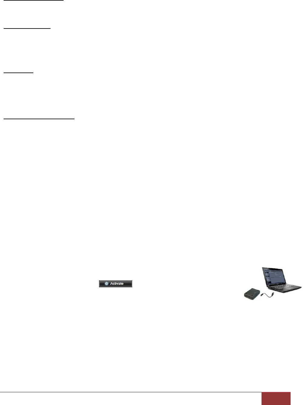
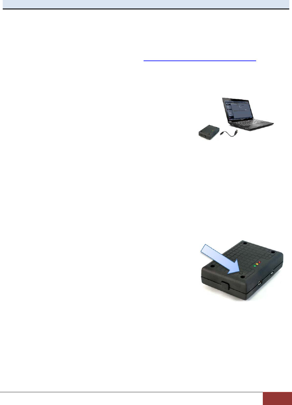
Activating VuLink
After your desired settings have been entered, attach VuLink to your computer
using the supplied USB cable. Your computer will recognize VuLink as a
removable disk drive. Press the button. You’ll then be prompted to
choose a location to save the configuration file named “deviceconfig”. Save this
configuration file onto your VuLink device. After the file has been transferred to
the VuLink, it may be unplugged from your computer.
VuLink Operation & Installation Guide 860‐00198‐00 REV E
DigitalAlly,Inc.|VuLinkConfiguration4‐4
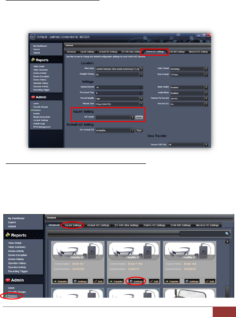
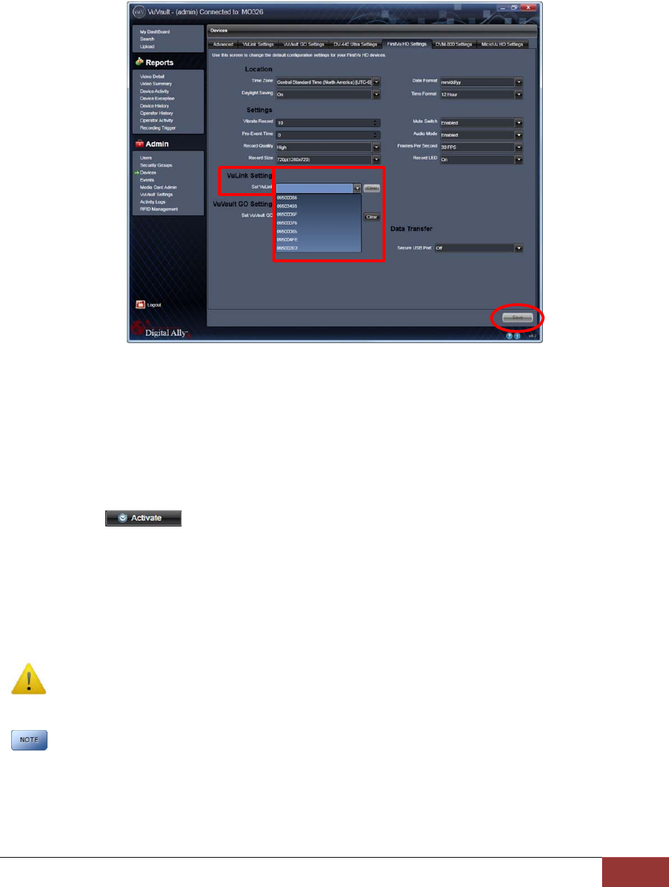
Assigning Your FirstVu HD to a VuLink Device
Method A: Global VuLink Setting Method
Using this method, all of your FirstVU HD’s will associate to a single VuLink device serial
number. Go to Admin>Devices>FirstVu HD Settings tab, use the drop down arrow
under VuLink Setting to assign a VuLink serial number to your FirstVu HD. When done,
press Save.
Method B: Unique VuLink Setting Method (preferred method)
In most cases, you will want to assign each FirstVu HD in your fleet to a different VuLink
device. Using this method, unintentional triggers will not occur if two fleet vehicles are in
close proximity to each other.
To make a unique VuLink association for each FirstVu HD, go to
Admin>Devices>Advanced and select the FirstVu HD device you wish to assign.
Select Settings.
VuLink Operation & Installation Guide 860‐00198‐00 REV E
DigitalAlly,Inc.|VuLinkConfiguration4‐5
You may now override the default device settings. Check the box next to VuLink Setting
and select a VuLink serial number to assign to your FirstVu HD device. When done, press
Save.
Activating FirstVu HD within VuVault
After you have assigned your FirstVu HD to a Vulink device serial number, proceed to
Admin>Media Card Admin to activate your FirstVu HD. Before activation, be sure to upload
any existing videos into VuVault.
1. Turn on your FirstVu HD & plug it into your computer using the supplied USB cable.
2. Select FirstVu HD as the device type. Click Refresh and the FirstVu HD will be displayed
as a removable drive.
3. Highlight the drive with your mouse.
4. Select . When done, unplug your FirstVu HD.
5. All done! Your FirstVu HD is now ready for use with VuLink.
Using Configuration Manager to Configure your VuLink and FirstVu HD
VuLink must be configured prior to use. Configuration for VuLink is determined by the
configuration file that is saved to the device from Digital Ally’s VuVault™ back-office software, or
by using the Mini Configuration Manager supplied on the internal memory.
Using VuVault™ to manage your devices is preferred, but not required. If you are not
utilizing VuVault, follow the instructions in this section to configure and activate your
device using the stand-alone Mini Configuration Manager software.
Using this method, you will assign all of your FirstVu HD’s to a single VuLink by creating
a configuration file. To set up multiple VuLink configurations, repeat the following process
for each VuLink device and save the new configuration file to VuLink and associated
FirstVu HD’s.
VuLink Operation & Installation Guide 860‐00198‐00 REV E
DigitalAlly,Inc.|VuLinkConfiguration4‐6
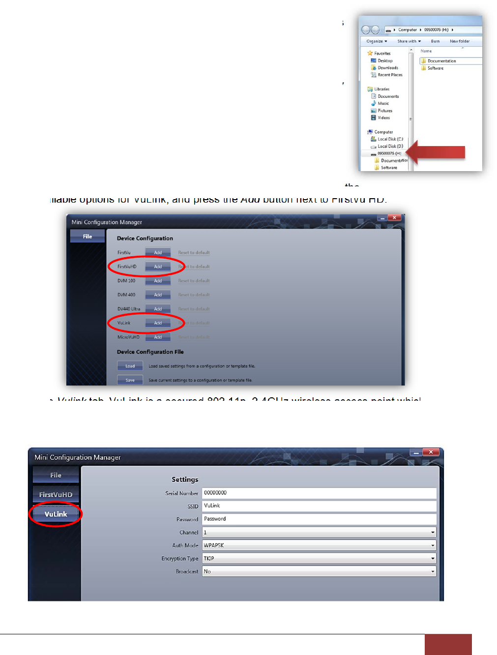
Installing the Software
1. Your VuLink is preloaded with software and documentation files
located on its internal memory. Plug VuLink into a computer
using the included USB cable to access these files.
2. The Documentation folder contains the Operation Guide and
Quick Start Guide. The Software folder contains the Digital Ally
Mini Configuration Manager and Basic Viewer software.
3. Open the Software folder and run the Digital Ally Viewer
installer. This will install all necessary files to your computer.
Configuring VuLink
Open the Mini Configuration Manager. Press the Add button to display the
list of available options for VuLink, and press the Add button next to FirstVu HD.
Select the Vulink tab.VuLink is a secured 802.11n, 2.4GHz wireless access point which your
FirstVu HD’s will use to communicate with your in-car video system and/or auxiliary sensors
(such as lights, siren, etc.). After you have made your selections, return to the File tab to save
your settings.

VuLink Operation & Installation Guide 860‐00198‐00 REV E
DigitalAlly,Inc.|VuLinkConfiguration4‐7
Settings
Serial Number
Your VuLink device has a unique 8 digit serial number printed on the unit. Enter the
serial number here without the dash (example 0950-0076 would be entered 09500076).
SSID The SSID is the wireless network name. This parameter specifies the VuLink SSID that
your FirstVu HD’s will be authorized to connect to. The SSID may be up to 10 digits in
length.
Password
This parameter specifies the password or security phrase required to connect to VuLink.
Channel
This parameter specifies the wireless channel that your FirstVu HD’s will use to connect
to VuLink.
Settings: 1 to 11, 1 [default]
Authentication Mode
This parameter specifies the security authentication required by VuLink.
Settings: WPAPSK, WPA2PSK
Encryption Type
This parameter specifies the wireless encryption protocol required by VuLink. If selecting
WPA2PSK (preferred) as the authentication mode, choose AES as the encryption type. If
selecting WPAPSK as the authentication mode, choose TKIP as the encryption type.
Settings: TKIP, AES
Broadcast
Choose whether or not to broadcast the SSID. Broadcasting allows computers with
wireless cards to find the network by browsing. Disabling the broadcast of the SSID
prevents browsing to find the network.
Settings: On, Off [default]
Ignition Shutdown Timer
The Ignition Shutdown Timer specifies the amount of time VuLink remains fully powered
when the vehicle ignition goes from ON to OFF.
Settings: 0 to 50 minutes, 1 hr, 2 hrs, 4 hrs, 8 hrs, 12 hrs, 24 hrs, and Unlimited [default = 1 hour]
DuringtheIgnitionShutdownTime:
7. If configured to 0 minutes; the Ignition Shutdown Timer is disabled, and VuLink will shut
down when ignition is turned off.
8. If the FirstVu HD is not recording, all LED Indicators will turn off, but VuLink will remain
fully powered until the timer expires.
9. During an active record, the FirstVu HD will continue recording and the system status
indicators will operate normally until the recording ends.
10. If the Ignition Shutdown Timer has not expired, the unit will allow an event record start
from any of the available Event Record Start Triggers. If a recording begins, the system
indicators will operate normally until the recording ends.
11. Once the Ignition Shutdown Timer expires, the system will stop an active recording.
12. If the vehicle ignition is turned ON before the timer expires, the Ignition Shutdown Timer
is cancelled and will start over again when the ignition is turned off.
VuLink Operation & Installation Guide 860‐00198‐00 REV E
DigitalAlly,Inc.|VuLinkConfiguration4‐8
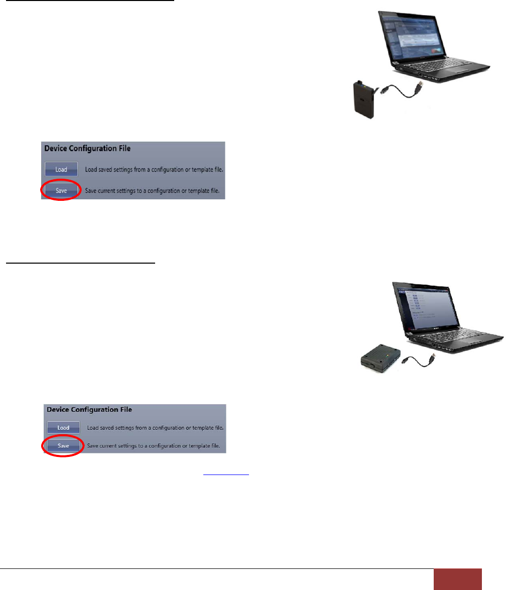
Saving your Settings
From the File tab, review your FirstVu HD settings and verify they are correct. For more
information on FirstVu HD settings, consult the FirstVu HD Operation Guide. To complete the
activation, you must write the configuration file named “deviceconfig” to your FirstVu HD and
Vulink devices. Once the file is written, the devices can communicate wirelessly.
Saving your FirstVu HD settings
1. Plug in your FirstVu into the computer using the supplied
USB cable. Your computer will recognize it as a removable
drive and the serial number will be displayed.
2. From the File Tab, Select Save. You’ll be prompted to select
the location of your FirstVu HD device. You may also wish
to back up the configuration file to a location on your
computer’s hard drive. The
configuration file named “deviceconfig” will be saved.
3. After saving the file, reboot your FirstVu HD and unplug the USB cable. The FirstVu HD
is now ready to be used with VuLink.
Saving your VuLink Settings
1. Connect VuLink to your computer through the supplied USB
cable. Your computer will recognize it as a removable drive
and the serial number will be displayed.
2. From the File Tab, Select Save. You’ll be prompted to select
the location of your Vulink device. You may also wish to back
up the configuration file to a location on your computer’s hard
drive. The configuration file named “deviceconfig” will be
written to VuLink.
3. Unplug the USB cable and go to Section 2 to install VuLink in your vehicle.
VuLink Operation & Installation Guide 860‐00198‐00 REV E
DigitalAlly,Inc.|VuLinkConfiguration4‐9
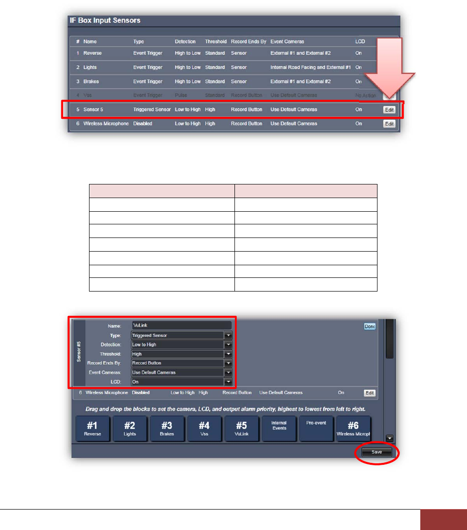
DVM-800, DVM-250, and DVM-250Plus Device Configuration
If you have a Digital Ally DVM-800, or DVM-250 series video system, you must assign the
VuLink output trigger to an IF box input sensor. Using this configuration, the FirstVu HD will be
enabled to trigger device recordings and have a customized trigger name. From your VuVault
or Configuration Manager Settings tab, enable the desired sensor to be used with VuLink. This
customized name will become a searchable parameter if using VuVault.
1. Go to the IF Box Input Sensors section. Select the Sensor 5 row (or any unused sensor
input) and press Edit.
2. Select a name for the Sensor #5 VuLink sensor. Make the changes to this sensor input
as listed in the table below. When done, press Save.
Parameter Required User Setting
Name Type a custom name here
Type Triggered Sensor
Detection Low to High
Threshold High
Record Ends By Record Button
Event Cameras Use Default Cameras
LCD On
3. You will need to re-activate your DVM with the new device configuration. Consult your
device Operation Guide for activation instructions.
VuLink Operation & Installation Guide 860‐00198‐00 REV E
DigitalAlly,Inc.|Operation5‐1
Section‐5: Operation
Power Control
Power to VuLink is controlled through your vehicle’s ignition. There are no manual controls for
powering the unit on and off. When ignition is cycled, the boot-up process will begin. The red
and yellow status indicators will flash until boot up is complete. When ignition is turned off,
VuLink will enter low power standby mode. The Green LED will continue to be illuminated when
ignition is off.
Testing the System
1. The Green status indicator will be illuminated whenever battery power is present,
regardless of the ignition switch position.
2. Turn on your vehicle’s ignition. The yellow and red status indicators will blink sequentially
as VuLink is booting up.
3. Once the boot-up process is complete, the Yellow status indicator will flash as VuLink
tries to establish a wireless connection with your configured FirstVu HD’s.
4. When a wireless link is established, the Yellow status indicator on VuLink will remain lit
as long as the FirstVu HD is within range. Typical range is 50ft.
5. The Yellow status indicator will also remain illuminated on the FirstVu HD.
6. Power on your In-Car Video system (ICV).
7. Start a recorded event by activating your emergency lights.
8. The Red status indicator on VuLink will turn on to indicate the event is being recorded.
The Red status indicator on the FirstVu HD and ICV should also turn on indicating that
they are also recording.
Whenever VuLink is connected to a FirstVu HD and the system is actively
recording, all 3 VuLink status indicators will remain illuminated.
9. After 10 seconds, press the RECORD STOP button on your ICV to stop the recorded
event. Press the stop button on your FirstVu HD. All Red status indicators on the ICV,
VuLink, and FirstVu HD will turn off.
10. Press the record button on your FirstVu HD to start a new recording. All Red status
LED’s on VuLink, FirstVu HD, and ICV will illuminate to indicate the system is recording.
11. Press the RECORD Stop button on your ICV to stop the recorded event. Press the stop
button on your FirstVu HD. All Red status LED’s on the DVM, VuLink, and FirstVu HD
will turn off.
Covert Mode
Press & hold the covert button on the left side of
VuLink for a few seconds to temporarily turn off all
status LED’s until the next power cycle. Press the
covert button again to return to normal LED mode.
CovertButton
VuLink Operation & Installation Guide 860‐00198‐00 REV E
DigitalAlly,Inc.|Operation5‐2
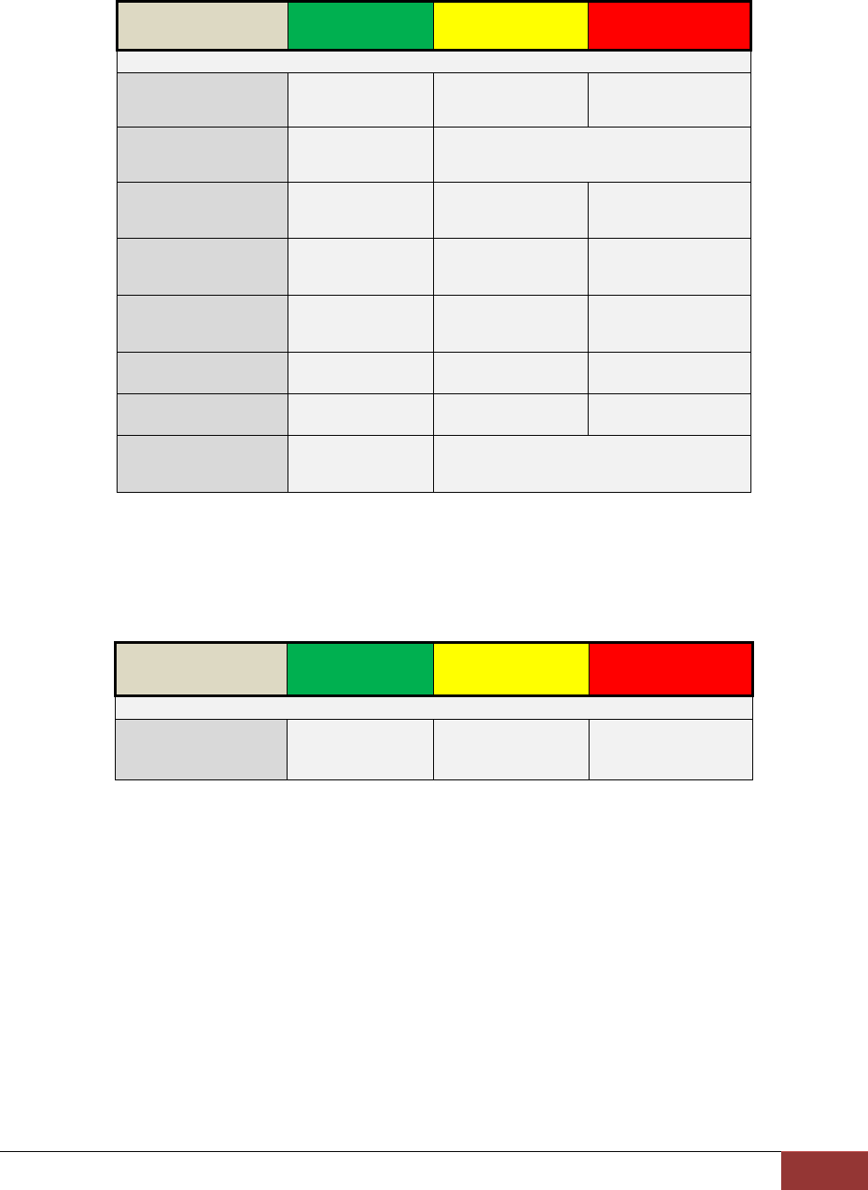
VuLink™ LED Status Indicators
GREENYELLOWRED
BatteryPower
presenttoVuLinkON‐‐ ‐‐
Power‐on
SequenceONAlternatingFlash
Searchingfor
WirelessLink‐‐ Flash‐‐
WirelessLink
Established‐‐ ON‐‐
Recordin
Progress‐‐ ‐‐ ON
CovertModeOFFOFFOFF
IgnitionOffONOFFOFF
Firmware
UpgradeONAlternatingflash
FirstVu HD™ LED Status Indicator
The FirstVu HD yellow status LED will be illuminated whenever a wireless link is established
with VuLink. For a complete list of status indicators, consult the FirstVu HD Operation Guide.
GREENYELLOWRED
WirelessLink
Established‐‐ ON‐‐
VuLink Operation & Installation Guide 860‐00198‐00 REV E
DigitalAlly,Inc.|Support6‐1
Section‐6: Support
Firmware Updates
IMPORTANT!Before proceeding with the firmware update described below, make
sure the vehicle’s
ignition is turned on.
1. Get the latest software by logging on to http://www.digitalallyinc.com/login.cfm and
r
egister for an account to be an authorized user. By registering you will be able to
download all the latest firmware/software updates and will be notified of future
upgrades.
2. Download and unzip the VuLink firmware file.
3. Connect the computer to the VuLink using the supplied
USB cable and, using Windows Explorer, navigate to
the VuLink drive.
4. Copy the firmware file to the root directory of the VuLink.
The file name is: firmware.r
5. Right-click on the VuLink drive and select Eject, then disconnect the USB cable from
the device. The Green LED indicator should be on and the Yellow and Red indicators
will alternately flash while the new firmware is being installed. Wait for this operation to
complete.
6. Re-connect the USB and open the dvminfo file to verify the new firmware version.
7. Eject the VuLink drive and disconnect the USB cable.
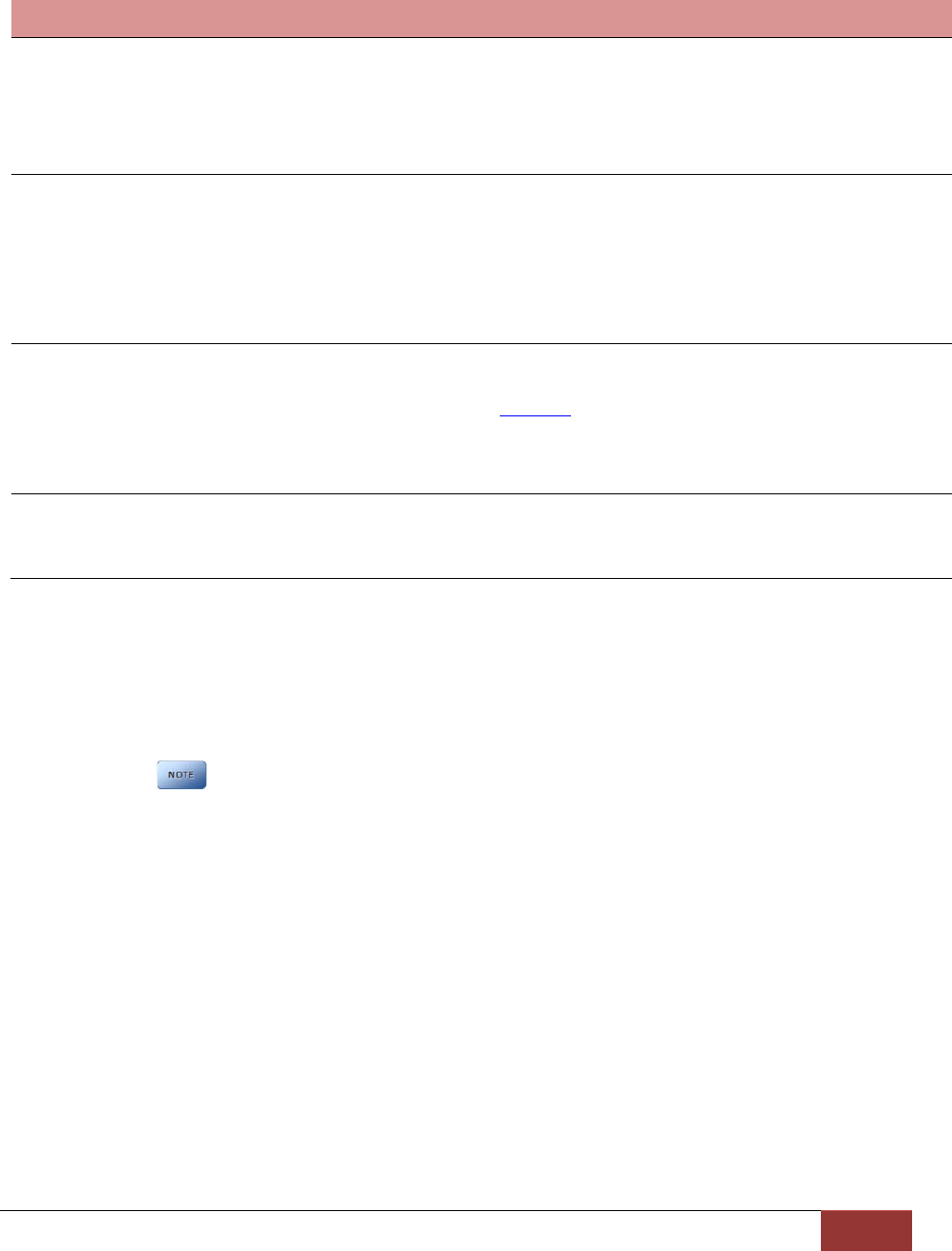
Performing a Reset
Using a small device such as a paper clip or eye-glass
screwdriver, press the recessed reset button that is located as
shown to the right. After a reset occurs, VuLink will determine if
a firmware file is present and read the deviceconfig file for
changes.
VuLink Operation & Installation Guide 860‐00198‐00 REV E
DigitalAlly,Inc.|Support6‐2
Troubleshooting
Symptom Resolution
Green Status indicator not lit
Verify the power cable connector is connected to VuLink.
Verify there are no breaks, pinches, or cuts in the wiring or cable harness.
Check the wiring and voltage levels to the red and black wires on the VuLink
cable harness. Should be constant 12VDC measured across these two
wires.
Red/Green status indicators
do not blink when ignition is
applied
Verify the power cable connector is connected to VuLink.
Verify there are no breaks, pinches, or cuts in the wiring or cable harness.
Check the wiring and voltage levels to the blue and black wires on
the VuLink cable harness. Should be constant 12VDC measured
across these two wires when ignition is active.
Reset the system
Yellow light is always
blinking / FirstVu HD will not
connect to VuLink
FirstVu HD is out of range or turned off.
FirstVu HD and/or VuLink not properly configured. Verify device
configurations in Section 4.
Reset the system.
Contact technical support if problem persists.
Poor wireless range
Ensure Vulink is properly mounted and no other vehicle antennas
or obstructions are nearby.
FirstVu HD battery may be low. Replace FirstVu HD battery.
Product Repair
VuLink should be returned to Digital Ally for service. The warranty may be voided if the device
is opened by any unauthorized individual. Please contact Digital Ally to obtain a Return
Materials Authorization (RMA). It is helpful and will expedite the process if you have your unit’s
serial number available at the time of your call.
All In-Warranty and Out-of-Warranty service must be performed by
Digital Ally, Inc. There are no user serviceable parts inside of VuLink.

VuLink Operation & Installation Guide 860‐00198‐00 REV E
DigitalAlly,Inc.|WarrantyInformation7‐1
Section‐7: WarrantyInformation
We warranty that VuLink™ will be free from defects in workmanship and material for a period of
12 months from the date of purchase by the original purchaser. If any defect is discovered
through normal and proper use of the unit during this period, the defect will be repaired or the
unit will be replaced at our factory or at one of our authorized service centers at no cost to the
purchaser. The purchaser must return the defective unit to the factory or one of our authorized
service centers, freight prepaid. We will pay for shipping charges for the return of the unit.
This warranty applies only to defects in a unit’s internal electronic components and circuitry,
and is void as to units that have been opened without prior authorization, have experienced
unauthorized repairs, or have had unauthorized modifications. This warranty does not cover the
following:
Normal wear and tear on the unit such as batteries, frayed cables or wires, broken
connectors, or scratched or broken cases.
Damage caused by operator abuse or neglect.
Damage caused by incorrect use of the unit, carelessness, unauthorized alterations
to the unit, improper storage of the unit or unauthorized service, installation or repairs
made to the unit.
Damage caused by fire, flood, lightning, vandalism, collision, acts of God, or
other events beyond the reasonable control of Digital Ally, Inc. or the purchaser.
Damage to external parts of the unit such as buttons, wires, and cables, etc.
Damage from use of the unit in hostile operating environments.
We reserve the right to charge for repairs to a unit during the warranty period made necessary
because of any of the foregoing causes at our standard rates for repair of units not under
warranty.
The purchaser assumes all risk of use from its purchase and use of the unit. Harmful personal
contact with a unit might occur in the event of violent maneuvers, collisions, or similar
circumstances, even if the unit was properly installed and used. We are not responsible for, and
we specifically disclaim any liability for injury caused by a unit in such circumstances.
THIS WARRANTY IS GIVEN IN LIEU OF ALL OTHER WARRANTIES. THERE ARE NO
WARRANTIES THAT EXTEND BEYOND THIS STATEMENT. ALL IMPLIED WARRANTIES ARE
DISCLAIMED, INCLUDING, WITHOUT LIMITATION, WARRANTIES OF MERCHANTABILITY, NON-
INFRINGEMENT, FITNESS FOR A PARTICULAR PURPOSE, AND WARRANTIES IMPLIED FROM A
COURSE OF DEALING, COURSE OF PERFORMANCE OR USAGE OF TRADE. THE PURCHASER’S
SOLE AND EXCLUSIVE REMEDY FOR A WARRANTY CLAIM WILL BE THE REPAIR OR
REPLACEMENT OF A UNIT.

VuLink Operation & Installation Guide 860‐00198‐00 REV E
DigitalAlly,Inc.|ContactInformation8‐1
Section‐8: ContactInformation
9705 Loiret Blvd
Lenexa, KS 66219
Website: www.digitalallyinc.com
Support E-Mail: support@digitalallyinc.com
Sales E-Mail: sales@digitalallyinc.com
Phone: 913-814-7774
Fax: 913-814-7775
Sales / Support Toll Free: 1-800-440-4947
*Specificationssubjecttochangewithoutnotice.

VuLink Operation & Installation Guide 860‐00198‐00 REV E
DigitalAlly,Inc.|Regulatory9‐1
Section‐9: Regulatory
This device complies with Part 15 of the FCC Rules. Operation is subject to the following two
conditions: (1) This device may not cause harmful interference, and (2) This device must accept
any interference received, including interference that may cause undesired operation.
This equipment has been tested and found to comply with the limits for a Class B digital device,
pursuant to part 15 of the FCC Rules. These limits are designed to provide reasonable
protection against harmful interference in a residential installation. This equipment generates
uses and can radiate radio frequency energy and, if not installed and used in accordance with
the instructions, may cause harmful interference to radio communications. However, there is
no guarantee that interference will not occur in a particular installation. If this equipment does
cause harmful interference to radio or television reception, which can be determined by turning
the equipment off and on, the user is encouraged to try to correct the interference by one or
more of the following measures:
Reorient or relocate the receiving antenna.
Increase the separation between the user equipment and VuLink.
Connect the user equipment into an outlet on a circuit different from that to which VuLink
is connected.
Contact Digital Ally technical support.
This equipment complies with the FCC and Industry Canada RF radiation exposure limits set
forth for an uncontrolled environment. This equipment should be installed and operated with a
minimum distance of 20cm between the radiator and any part of your body.
This device complies with Industry Canada license-exempt RSS standard(s). Operation is
subject to the following two conditions: (1) this device may not cause interference, and (2) this
device must accept any interference, including interference that may cause undesired operation
of the device.
Le présent appareil est conforme aux CNR d'Industrie Canada applicables aux appareils radio
exempts de licence. L'exploitation est autorisée aux deux conditions suivantes : (1) l'appareil ne
doit pas produire de brouillage, et (2) l'utilisateur de l'appareil doit accepter tout brouillage
radioélectrique subi, même si le brouillage est susceptible d'en compromettre le
fonctionnement.
The CE Mark is a European marking of conformity indicating that a product complies with the
essential requirements of the applicable European laws or Directives with respect to safety,
health, environment, and consumer protection.
Changes or modifications not expressly approved by Digital Ally, Inc. could void the user’s
authority to operate the equipment.