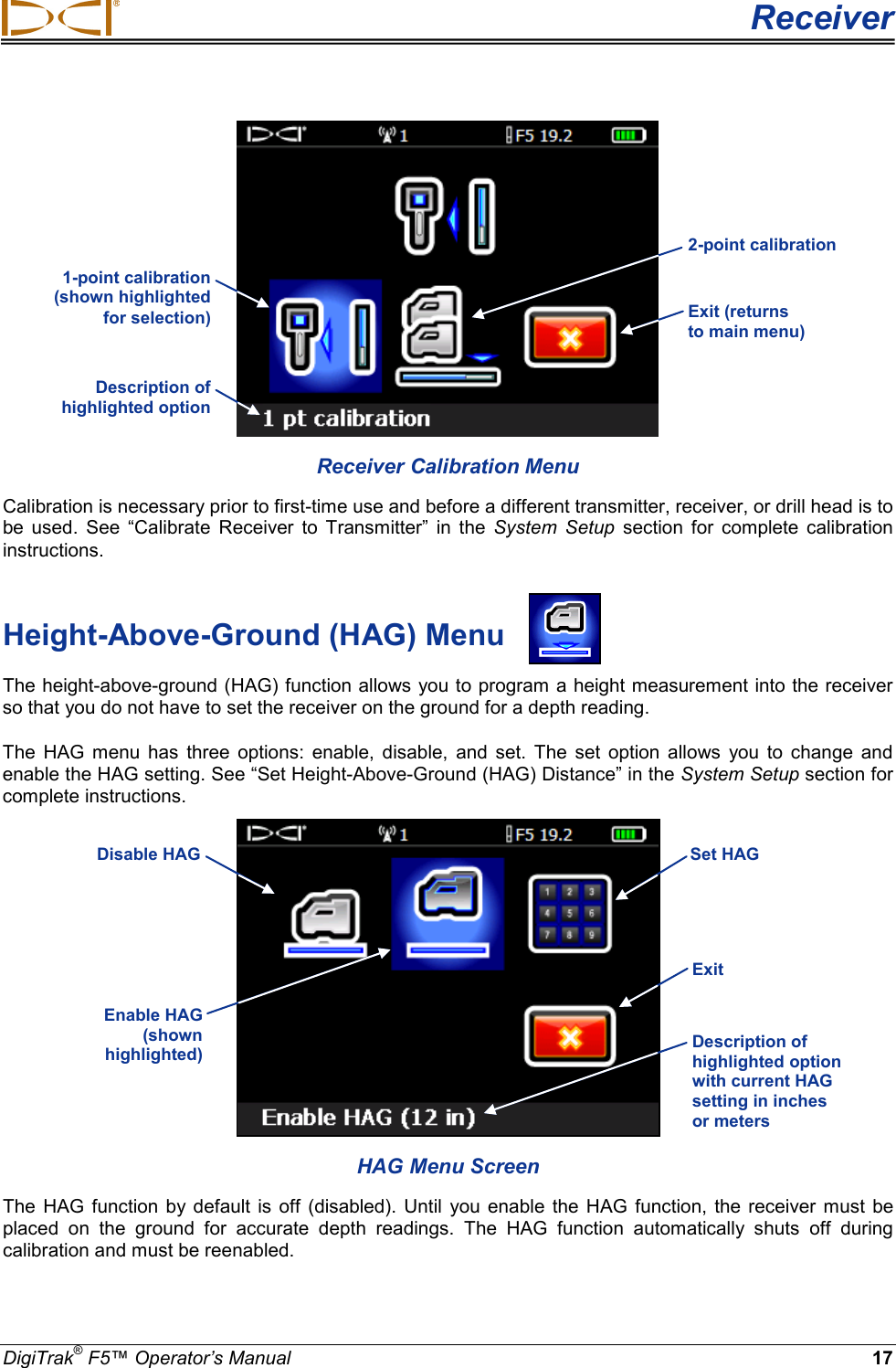
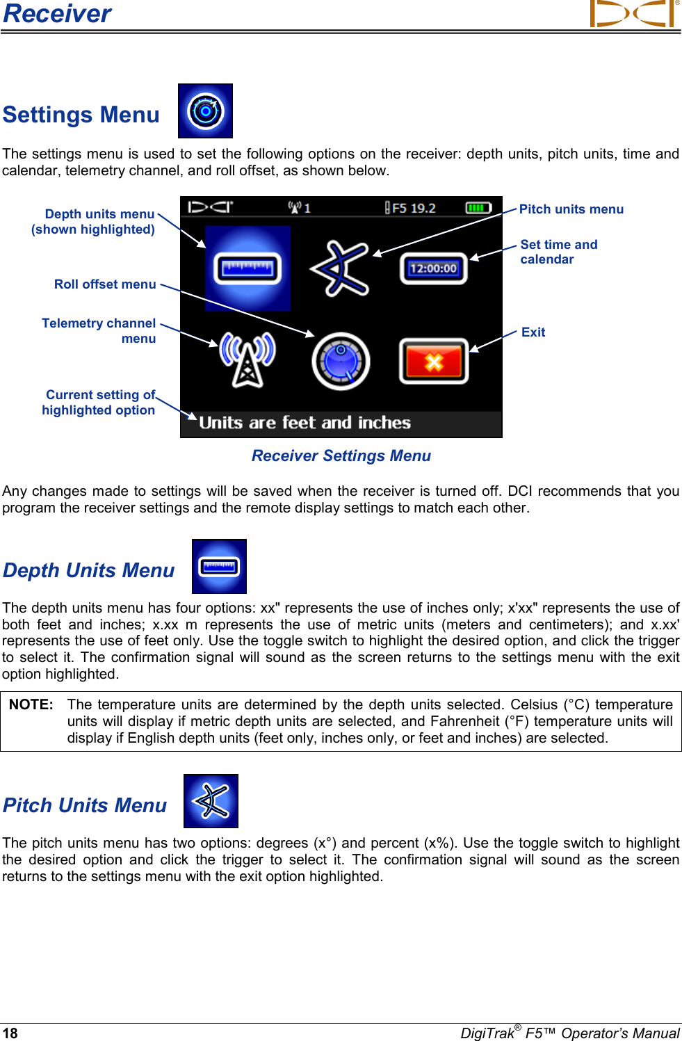
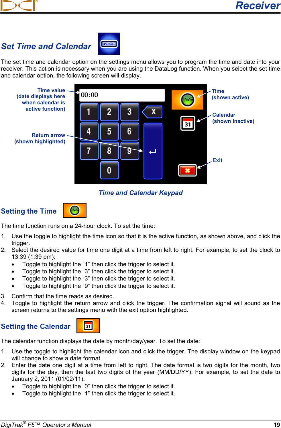
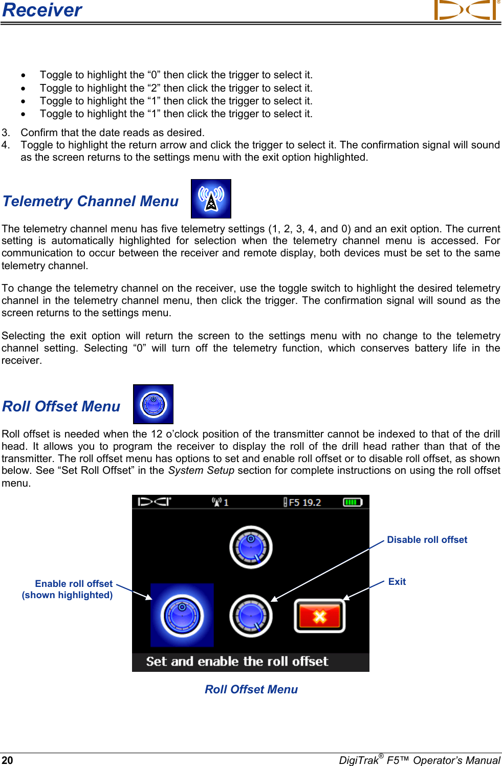
Digital Control A040412 DDS 12, DDT 12 User Manual Operating Instructions

Digital Control Inc DDS 12, DDT 12 Operating Instructions

User Manual

                       Directional Drilling Locating System  Operator’s Manual                    DIGITAL CONTROL INCORPORATED DCI Headquarters 19625 62nd Ave. S., Suite B-103 Kent, Washington  98032 USA Tel  425 251 0559 / 800 288 3610  Fax  253 395 2800 E-mail  DCI@digital-control.com  www.digitrak.com  DCI Europe Kurmainzer Strasse 56 D-97836 Bischbrunn  Germany Tel +49(0) 9394 990 990 Fax +49(0) 9394 990 999 DCI.Europe@digital-control.com DCI India DTJ 1023, DLF Tower A Jasola District Center New Delhi 110 044, India Tel +91(0) 11 4507 0444 Fax +91(0) 11 4507 0440 DCI.India@digital-control.com DCI China No. 368, Xingle Road Huacao Town, Minhang District Shanghai P.R.C. 201107  Tel +86(0) 21 6432 5186 Fax +86(0) 21 6432 5187 DCI.China@digital-control.com DCI Australia 2/9 Frinton Street Southport, Queensland 4215 Australia Tel +61(0) 7 5531 4283 Fax +61(0) 7 5531 2617 DCI.Australia@digital-control.com DCI Russia 420059 Pavlyukhina Street  104, Kazan Russia Tel +7 843 277 52 22 Fax +7 843 277 52 07 DCI.Russia@digital-control.com
DIGITAL CONTROL INCORPORATED    2  DigiTrak® F5™ Operator’s Manual 3-2500-00-C    © 2010-2011 by Digital Control Incorporated. All rights reserved. June 2011.  Trademarks The DCI logo, CableLink®, DataLog®, DigiTrak®, Eclipse®, F2®, iGPS®, MFD®, SST®,  target-in-the-box®, Target Steering®, and TensiTrak® are U.S. registered trademarks and DucTrak™, F5™, F Series™, FSD™, FasTrak™, LT™, LT2™, LWD™, SE™, SED™, SuperCell™, and TeleLock™ are trademarks of Digital Control Incorporated. Limited Warranty All products manufactured and sold by Digital Control Incorporated (DCI) are subject to the terms of a Limited Warranty. A copy of the Limited Warranty is included at the end of this manual; it can also be obtained by contacting DCI Customer Service, 425-251-0559 or 800-288-3610, or by connecting to DCI's website, www.digitrak.com. Important Notice All statements, technical information, and recommendations related to the products of DCI are based on information believed to be reliable, but the accuracy or completeness thereof is not warranted. Before utilizing any DCI product, the user should determine the suitability of the product for its intended use. All statements herein refer to DCI products as delivered by DCI and do not apply to any user customizations not authorized by DCI nor to any third-party products. Nothing herein shall constitute any warranty by DCI nor will anything herein be deemed to modify the terms of DCI’s existing Limited Warranty applicable to all DCI products. FCC Compliance Statement This device complies with Part 15 of the Rules of the FCC. Operation is subject to the following two condi-tions: (1) this device may not cause harmful interference, and (2) this device must accept any interference received, including interference that may cause undesired operation. DCI is responsible for FCC compli-ance in the United States: Digital Control Incorporated, 19625 62nd Ave. S., Suite B-103, Kent, WA 98032; phone 425-251-0559 or 800-288-3610. Changes or modifications to the DCI equipment not expressly approved and carried out by DCI will void the user’s Limited Warranty and the FCC’s authorization to operate the equipment. CE Requirements   DigiTrak receivers are classified as Class 2 radio equipment per the R&TTE Directive and may not be legal to operate or require a user license to operate in some countries. The list of restrictions and the required declarations of conformity are available on DCI’s website, www.digitrak.com, under the Service & Support tab. Click on DOWNLOADS and select from the CE Documents pull-down menu to download, view, or print the documents.
 DIGITAL CONTROL INCORPORATED  DigiTrak® F5™ Operator’s Manual 3 Table of Contents  SAFETY PRECAUTIONS AND WARNINGS ................................................................................................ 6 DEAR CUSTOMER: ...................................................................................................................................... 8 INTRODUCTION ........................................................................................................................................... 9 RECEIVER .................................................................................................................................................. 11 General Description ................................................................................................................................. 11 Toggle and Trigger Switches ................................................................................................................... 12 Audible Tones .......................................................................................................................................... 12 Installing and Removing the Battery Pack............................................................................................... 12 Power On ................................................................................................................................................. 13 Power Off ................................................................................................................................................. 14 Main Menu ............................................................................................................................................... 14 Locate Mode ............................................................................................................................................ 16 Calibration Menu ..................................................................................................................................... 16 Height-Above-Ground (HAG) Menu ........................................................................................................ 17 Settings Menu .......................................................................................................................................... 18 Depth Units Menu ................................................................................................................................ 18 Pitch Units Menu .................................................................................................................................. 18 Set Time and Calendar ........................................................................................................................ 19 Setting the Time ............................................................................................................................... 19 Setting the Calendar ........................................................................................................................ 19 Telemetry Channel Menu .................................................................................................................... 20 Roll Offset Menu .................................................................................................................................. 20 Transmitter Selection Menu .................................................................................................................... 21 Drill DataLog Menu .................................................................................................................................. 22 Pressure-Tension DataLog Menu ........................................................................................................... 23 Using the Keypad .................................................................................................................................... 25 Display Screens ....................................................................................................................................... 26 Locate Mode Display Screen ............................................................................................................... 26 Depth Mode Display Screen ................................................................................................................ 27 Predicted Depth Display Screen .......................................................................................................... 28 Depth Display Screen, No Data ........................................................................................................... 28 Standard Receiver Display Screen Symbols .......................................................................................... 29 TRANSMITTER ........................................................................................................................................... 31 General Description ................................................................................................................................. 31 Types of F5 Transmitters......................................................................................................................... 31 Batteries and Power On/Off .................................................................................................................... 33 Installing Batteries / Power On ............................................................................................................ 33 Transmitter Battery Status ................................................................................................................... 35 Sleep Mode (Automatic Shutdown) / Power Off .................................................................................. 35 Transmitter Housing Requirements ......................................................................................................... 35 Transmitter Selection ............................................................................................................................... 37 Changing the Frequency of a “19/12” Dual-Frequency Transmitter ....................................................... 39 Pitch Method ........................................................................................................................................ 39 Roll Method .......................................................................................................................................... 39
DIGITAL CONTROL INCORPORATED    4  DigiTrak® F5™ Operator’s Manual Table of Contents (Continued)  TRANSMITTER (Continued) Temperature Status and Overheat Indicator ........................................................................................... 40 Transmitter Temperature Warning Tones............................................................................................ 40 Transmitter Overheat Indicator (Temp Dot) ......................................................................................... 41 REMOTE DISPLAY ..................................................................................................................................... 43 General Description ................................................................................................................................. 43 Power Options ......................................................................................................................................... 44 Installing and Removing the Battery Pack or Brace Insert .................................................................. 44 Connecting the DC Power Cable ......................................................................................................... 44 Keypad .................................................................................................................................................... 45 Power On/Off ........................................................................................................................................... 45 Audible Tones .......................................................................................................................................... 45 Adjusting Screen Contrast ....................................................................................................................... 45 Adjusting the Viewing Angle .................................................................................................................... 46 Attaching / Removing Visor ..................................................................................................................... 46 Main Menu ............................................................................................................................................... 47 Remote Mode .......................................................................................................................................... 48 Settings Menu .......................................................................................................................................... 48 Contrast Adjustment ................................................................................................................................ 49 Display Screens ....................................................................................................................................... 50 Main Display Screen ............................................................................................................................ 50 Depth Display Screen .......................................................................................................................... 51 Predicted Depth Display Screen .......................................................................................................... 52 BATTERY CHARGER ................................................................................................................................. 53 General Description ................................................................................................................................. 53 Checking Battery Status .......................................................................................................................... 53 AC/DC Power Setup ................................................................................................................................ 54 Charging a Battery Pack.......................................................................................................................... 54 Battery Charger LED Indicators .............................................................................................................. 54 Warnings and Precautions ...................................................................................................................... 55 SYSTEM SETUP ........................................................................................................................................ 57 Power on Receiver, Remote, and Transmitter ........................................................................................ 57 Receiver ............................................................................................................................................... 57 Remote Display .................................................................................................................................... 57 Transmitter ........................................................................................................................................... 58 Conduct Interference Check .................................................................................................................... 58 What Interference Is and How to Check for It ...................................................................................... 58 Background Noise Check .................................................................................................................... 58 Roll/Pitch Check ................................................................................................................................... 59 Suggestions for Dealing with Interference ........................................................................................... 60 Calibrate Receiver to Transmitter ............................................................................................................ 60 1-Point Calibration (Above Ground)  .................................................................................................... 61 2-Point Calibration (In Ground) ............................................................................................................ 63
 DIGITAL CONTROL INCORPORATED  DigiTrak® F5™ Operator’s Manual 5 Table of Contents (Continued)  SYSTEM SETUP (Continued)  Set Roll Offset ......................................................................................................................................... 65 Enable Roll Offset ................................................................................................................................ 65 Disable Roll Offset ............................................................................................................................... 66 Set Height-Above-Ground (HAG) Distance ............................................................................................. 67 LOCATING .................................................................................................................................................. 69 Locating Basics ....................................................................................................................................... 70 Locate Points (FLP & RLP) and Locate Line (LL) ............................................................................... 70 Effects of Depth, Pitch, and Topography on  Distance Between FLP and RLP .................................. 71 Marking Locate Points ......................................................................................................................... 72 Standard Method for Locating the Transmitter ........................................................................................ 73 Finding the Front Locate Point (FLP)................................................................................................... 73 Finding the Locate Line (LL) ................................................................................................................ 75 Finding the RLP to Confirm Transmitter Heading and Position ........................................................... 77 Tracking “On-the-Fly” .............................................................................................................................. 79 Off-Track Locating ................................................................................................................................... 80 THE TARGET STEERING FUNCTION ...................................................................................................... 83 Feasible Target Depth and  Positioning the Receiver as a Target ......................................................... 83 Programming the Receiver for Target Steering ...................................................................................... 84 Steering to the Target .............................................................................................................................. 85 Target Steering in Interference Areas ..................................................................................................... 87 Turn Off Target Steering.......................................................................................................................... 87 APPENDIX A: SYSTEM SPECIFICATIONS AND MAINTENANCE REQUIREMENTS ............................ 89 Power Requirements ............................................................................................................................... 89 Environmental Requirements .................................................................................................................. 89 General Transmitter Care Instructions .................................................................................................... 90 Battery Pack Storage ............................................................................................................................... 90 APPENDIX B: PROJECTED DEPTH VERSUS ACTUAL DEPTH AND THE FORE/AFT OFFSET .......... 91 APPENDIX C: CALCULATING DEPTH BASED ON DISTANCE BETWEEN FLP AND RLP ................... 97 APPENDIX D: REFERENCE TABLES ....................................................................................................... 99 Depth Increase in Inches (Centimeters) per 10-foot (3-meter) Rod ........................................................ 99 Depth Increase in Inches (Centimeters) per 15-foot (4.6-meter) Rod ................................................... 100 LIMITED WARRANTY
DIGITAL CONTROL INCORPORATED    6  DigiTrak® F5™ Operator’s Manual Safety Precautions  and Warnings Important Note:   All operators must read and understand the following Safety Precautions and Warnings and must review this operator’s manual before using the DigiTrak® F5™ Locating System.  Serious injury and death can result if underground drilling equipment makes contact with an underground utility such as a high-voltage electrical cable or a natural gas line.      Substantial property damage and liability can result if underground drilling equipment makes contact with an underground utility such as a telephone, cable  TV,  fiber-optic, water, or sewer line.     Work slowdowns and cost overruns can occur if drilling operators do not use the drilling or locating equipment correctly to obtain proper performance.   DCI equipment is not explosion-proof and should never be used near flammable or explosive substances.   Directional drilling operators MUST at all times: • Understand the safe and proper operation of drilling and locating equipment, including the use of ground mats and proper grounding procedures. • Ensure that all underground utilities have been located, exposed, and marked accurately prior to drilling. • Wear protective safety clothing such as dielectric boots, gloves, hard-hats, high-visibility vests, and safety glasses. • Locate and track the transmitter in the drill head accurately and correctly during drilling. •  Maintain a minimum distance of 8 in. (20 cm) from the front of the receiver to the user’s torso to ensure compliance with FCC requirements. • Comply with federal, state, and local governmental regulations (e.g., OSHA). • Follow all other safety procedures.  The DigiTrak F5 system cannot be used to locate utilities.  In the event of electrostatic shock, the display screen may go blank. No data loss will occur. Click the trigger to reset the receiver; toggle down to reset the remote display.  Continued exposure of the transmitter to  heat, due to frictional heating of the drill head, can cause inaccurate information to be displayed and may permanently damage the transmitter. For more infor-mation see the Transmitter section of this manual.   CAUTION:  Hot surfaces can occur on the FC, ECP, and SST cable transmitters if housing requirements are not met. Always ensure that the transmitter is installed properly in the housing during use.
 DIGITAL CONTROL INCORPORATED  DigiTrak® F5™ Operator’s Manual 7 Safety Precautions  and Warnings (Continued)  BATTERY DISPOSAL: This symbol on equipment indicates that the equipment must not be disposed of with your other household waste. Instead, it is your responsibility to dispose of such equipment by handing it over to a designated collection point for the recycling of batteries or electrical and electronic equipment. If the equipment contains a banned substance, the label will show the pollutant (Cd = Cadmium; Hg = Mercury; Pb = Lead) near this symbol. The separate collection and recycling of your waste equipment at the time of disposal will help to conserve natural resources and ensure that it is recycled in a manner that protects human health and the environment. For more information about where you can drop off your waste equipment for recycling, please contact your local city office, your household waste disposal service, or the shop where you purchased the equipment.    The battery charger provided with the DigiTrak F5 system is designed with adequate safeguards to protect you from shock and other hazards when used as specified within this document. If you use the battery  charger in a manner not specified by this document, the protection provided may be impaired. Do not attempt to disassemble the battery charger. It contains no user-serviceable parts. The battery charger is not to be installed into caravans, recreational vehicles, or similar vehicles.  Remove the batteries from all system components during shipping and prolonged storage; damage caused by leakage may occur.  Before each drilling run, test the DigiTrak F5 system with the transmitter inside the drill head to con-firm that it is operating properly and is providing accurate drill head location and heading information.  During drilling, the depth will not be accurate unless: • The receiver has been properly calibrated and the calibration has been checked for accuracy so that the receiver shows the correct depth. • The transmitter has been located correctly and accurately and the receiver is directly above the transmitter in the drill head underground or at the front locate point. • The receiver is held at the height-above-ground distance, which has been set correctly, or placed on the ground for depth measurements.  Always test calibration after you have stopped drilling for any length of time.  Interference can cause inaccuracies in the measurement of depth and loss of the transmitter’s pitch, roll, or heading. You should always perform a background noise check prior to drilling. • Sources of interference include but are not limited to traffic signal loops, invisible dog fences, cable TV, power lines, fiber-trace lines, metal structures, cathodic protection, telephone lines, cell phones,  transmission towers, conductive earth, salt,  salt water, rebar, radio frequencies, and other unknown sources of interference. • Interference with the operation of the remote display may also occur from other sources operating nearby on the same frequency, such as car rental agencies using their remote check-in modules, other directional drilling locating equipment, etc. • Background noise must be minimal and signal strength must be at least 150 points above the background noise during all locating operations.  Carefully review this manual and be sure you  always  operate the DigiTrak F5 system properly to obtain accurate depth, pitch, roll, and locate points. If you have any questions about the operation of the system, please call DCI’s Customer Service Department at any of the phone numbers provided on the cover, and we will do our best to assist you.
DIGITAL CONTROL INCORPORATED    8  DigiTrak® F5™ Operator’s Manual    Dear Customer:  Thank you for choosing the DigiTrak® F5™ Locating System. We are proud of the equipment that we have been designing and building in Washington State since 1990. We believe in providing a unique, high-quality product and standing behind it with superior customer service and training.  Please take the time to read this entire manual—especially the section on safety. Also, please fill in the product registration card provided with this equipment, and mail it to DCI headquarters or fax it to us at 253-395-2800; you can also complete and submit the form online at our website. We will put you on the Digital Control mailing list and send you product upgrade information and our FasTrak™ newsletter.  Feel free to contact us at any of our global offices listed on the front cover if you have any problems or questions. Our Customer Service Department is available 24 hours a day, 7 days a week to provide assistance.  As the horizontal directional drilling industry grows, we’re keeping our eye on the future to develop equipment that will make your job faster and easier. Stay current by visiting our website on the internet at www.digitrak.com or by giving us a call.  We welcome questions, comments, and ideas.  Digital Control Incorporated Kent, Washington 2011
 DIGITAL CONTROL INCORPORATED  DigiTrak® F5™ Operator’s Manual 9 Introduction  DigiTrak F5 Locating System The DigiTrak F5 Locating System is used during horizontal directional drilling operations to locate and track a transmitter installed in the drill head. The system consists of a handheld receiver, a transmitter, a remote display with battery and cable power options,  a battery charger system, and three rechargeable battery packs for powering the receiver and remote.  There are several transmitter options available for use with the F5 system. These include five frequency options (1.3 kHz, 8.4 kHz, 12 kHz, 18.5 kHz, and 19.2 kHz),  dual-frequency transmitters, and a cable transmitter. The options also include fluid pressure transmitters (FPTs) that monitor the pilot hole annular mud  pressure,  the TensiTrak  transmitter that monitors the  pullback force between the reamer and the product being pulled, and the Short Steering Tool (SST) transmitter for drilling where walkover tracking is not possible.  The F5 system also has a DataLog function that allows you to record data points along the bore path. The drill data can then be uploaded to a computer with DigiTrak LWD (Log-While-Drilling) software installed, which  allows you to format, analyze, view,  and print DataLog files.  See the DigiTrak LWD DataLog System Operator’s Manual for complete information. F5 transmitter FXL transmitter Battery charger Receiver Remote display FS transmitter Rechargeable battery packs
Introduction      10 DigiTrak® F5™ Operator’s Manual This manual provides information on each F5 system component—the receiver, transmitter, remote dis-play, and battery charger—in separate sections following this Introduction.  The next section, System Setup, gives  information for setting up the system components prior to drilling, including verification of proper system communication and calibration.  Then, the  Locating section presents  step-by-step instructions for locating and tracking the transmitter, including the use of predicted depth, tracking on the fly, and off-track locating. This is followed by the Target Steering section, which explains how to use this function for navigating the drill head. Appendix A presents the F5 system’s power, environmental, and maintenance requirements. Appendix B explains how to calculate depth when the transmitter is deep (greater than 15 ft or 4.6  m) and/or at a steep pitch (greater than ±30% or ±17°).  Appendix C explains how to calculate depth based on the distance between the front and rear locate points and the pitch of the transmitter. Finally,  Appendix D provides calculated depth increases for 10-ft (3-m) and 15-ft (4.6-m) rods depending on pitch.
 DIGITAL CONTROL INCORPORATED  DigiTrak® F5™ Operator’s Manual 11 Receiver       F5 Receiver – Side and Back Views General Description The F5 receiver is a handheld unit used for locating, tracking, and mapping the path of an F5 or F Series transmitter.  The receiver converts signals from the transmitter and displays the following information: depth, pitch, roll, temperature, and battery level. When a fluid pressure transmitter is used, fluid pressure information is also displayed.  The F5 receiver  sends  this same information to the remote display at the drill rig.  To meet regional requirements and for proper communication, the telemetry frequency designation for the receiver must match that for the remote display. The telemetry frequency designation is identified on the receiver’s  serial number label, which is located inside the battery compartment. It must match one of those listed on the remote display’s serial number label located on the back of the unit (see Remote Display section). The receiver and transmitter must also meet specific operational requirements for different global regions. A regional designation number is provided in the receiver’s software (see figure titled “Receiver Startup Screen” later in this section and system information option on main menu). This number must match that stamped on the transmitter for proper communication (see Transmitter section). In addition, the receiver must be set to detect the transmitter  being used and be calibrated for use with that  transmitter (see System Setup section). Trigger switch Front panel Boot Battery tab Display screen Grip Battery compartment Toggle (thumb switch)   Telemetry frequency designation Serial number Handle
Receiver     12 DigiTrak® F5™ Operator’s Manual Toggle and Trigger Switches The F5 receiver has two types of switches for operating the system – a toggle (thumb switch) located on the top of the unit and a trigger located under the handle.  Toggle Switch – Used to access and navigate menus. Moves in four directions: left, right, up (toward the display), and down (toward the handle).  Trigger Switch – Used to turn on the receiver, to select menu options, and to change the screen view for depth readings. Is either clicked or held in, depending on the desired action.  Audible Tones The F5 receiver beeps to signal power on/off, to confirm menu changes, and to acknowledge the pass/fail status of actions, as summarized below. The receiver also beeps with transmitter temperature increases (see “Transmitter Temperature Warning Tones” in the Transmitter section).  Power On – A series of short beeps. Power Off – Four short beeps. Confirmation Signal – Four short beeps to confirm menu selection has been successfully executed.  Failure Signal – Two long beeps to indicate a problem with the menu option selected. A failure screen will appear. The failure screen will display until the trigger is clicked or the battery is removed in the case of a critical failure. Verify your setup and try the operation again or call DCI Customer Service for assistance. Installing and Removing the Battery Pack Insert a fully charged DigiTrak F Series battery pack so that it is flush with the back of the receiver and the tab is securely latched. To remove the battery pack, push down on the battery tab and pull it away from the unit until the tab is released. Then lift the battery pack out of the battery compartment.       Inserting Battery Pack Battery Pack Fully Inserted Removing Battery Pack To check the charge on the battery pack,  push the battery status button    located  under the LEDs below the battery tab. The LEDs will illuminate to indicate the amount of charge on the battery. See the Battery Charger section for more information. Battery tab
 Receiver DigiTrak® F5™ Operator’s Manual 13 Power On  To turn on the receiver, pull in and hold the trigger switch for at least 2 seconds, then release the trigger. A series of beeps will sound, and then a screen with the F5 logo will display while the receiver performs a self-test. The warning screen shown below will then display.  Receiver Warning Screen You must pull and release (click) the trigger switch to acknowledge that you have read and understand this manual. If all items of the self-test passed, the startup screen shown below will display.  Receiver Startup Screen Click the trigger to exit the startup screen and open the main menu (see “Main Menu” below). NOTE:  If an item of the self-test fails,  the warning symbol will display and a failure message  will appear in place of the system name. Contact DCI Customer Service for support.  Regional designation number (must match that of transmitter) System name   Receiver ID number Software version   Web address  Customer service phone numbers
Receiver     14 DigiTrak® F5™ Operator’s Manual Power Off To turn off the receiver, select the power off option in the main menu (see below). Four short beeps will sound as the unit turns off. Automatic Shutdown – The receiver will automatically shut down after 15 minutes of inactivity or after 30 minutes of inactivity when the receiver is in Target Steering mode. Main Menu  To access the main menu from the startup screen, click the trigger. When locating, you can access the main menu by pushing the toggle switch down (toward the handle). Use the toggle to highlight different menu options and click the trigger to select a menu option. The main menu appears on two different screens, as shown below. A down  arrow in the lower right corner indicates more menu options below (on the next screen); an up arrow indicates more options above (on the previous screen).   Receiver Main Menu, First Screen  Receiver Main Menu, Second Screen Receiver battery status (shown fully charged) Calibration menu Settings menu Transmitter selection menu  Locate mode  (blue color indicates option is highlighted for selection)  Power off Height-above-ground (HAG) menu Down arrow indicates more options below (toggle down to view)  Telemetry channel Description of  highlighted option  Drill DataLog menu Diagnostics Up arrow indicates more options above (toggle up to view)  System information Transmitter type  and frequency Pressure-tension  (P-T) DataLog menu
 Receiver DigiTrak® F5™ Operator’s Manual 15 The main menu screen also displays the receiver battery status (in the top right corner), the transmitter type and frequency setting (to the left of the battery status), and the current telemetry channel selection (channel 1 is shown in the example above). These items are displayed on all receiver menu screens.  The options available on the main menu are summarized below.  Receiver Main Menu Options  Locate Mode – Opens the locate mode screen where transmitter data is displayed. See “Locate Mode” below.  Power Off – Turns the unit off accompanied by four short beeps.   Calibration  Menu –  Calibrates the receiver to the transmitter using the above-ground (1-point) method or the below-ground (2-point) method. See “Calibration Menu” below.   Height-Above-Ground (HAG)  Menu  –  Turns  on, turns  off, or sets  the height at which the receiver will be held during depth readings. See “Height-Above-Ground (HAG) Menu” below.  Settings  Menu – Allows you to change  the depth units,  pitch units, telemetry channel, time, and date, and to activate the roll offset function, which is used when the transmitter’s roll position must be compensated to match the drill head’s roll position. See “Settings Menu” below.  Transmitter Selection Menu –  Displays the transmitter type and frequency options. See “Transmitter Selection Menu” below.  Drill DataLog Menu – Allows you to enable or disable the drill DataLog function, to set up new drill jobs, to view and delete drill jobs from the receiver, and to upload drill jobs to a computer with LWD software installed.  See  “Drill DataLog Menu” below.   Diagnostics – Allows you to conduct diagnostic tests on the receiver. If you have any questions, contact DCI Customer Service.  System Information – Displays system information including receiver ID number, software  and hardware versions,  telemetry region, regional designation number, receiver run time, and  Bluetooth ID and version numbers, which are needed for uploading DataLog files to a computer.   Pressure-Tension DataLog Menu – Allows you to enable or disable the pressure-tension DataLog function, to delete recorded pressure-tension jobs, and to upload recorded  pressure-tension jobs  to a computer with LWD software installed. See “Pressure-Tension DataLog Menu” below.
Receiver     16 DigiTrak® F5™ Operator’s Manual Locate Mode The locate mode option on the main menu opens the locate mode screen, which is the default screen for locating. When the receiver is detecting a signal from a transmitter, the locate mode screen provides real-time data about the transmitter’s location, temperature, pitch, roll, fluid pressure (when a fluid pressure transmitter is used), and signal strength. See “Display Screens” later in this section for more information about the locate mode screen.  Receiver Locate Mode Screen with Transmitter in Range  The roll/pitch meter shows the quality of the signal from the transmitter. When a transmitter is not in range, the roll/pitch meter will be empty and no transmitter data will display.  If you hold the trigger in at the locate mode screen, then  a  depth mode screen will display. There are three depth mode screens that may appear depending on the position of the receiver relative to the transmitter. See “Display Screens” later in this section for a description of each depth mode screen.    Calibration Menu The calibration menu allows you to calibrate the receiver to a transmitter with the transmitter above ground (1-point calibration) or below ground (2-point calibration). When you select the calibration menu, the calibration option previously used is highlighted for selection.  Locating Target (FLP or RLP) Transmitter Signal Strength Roll/Pitch Update Meter Roll Indicator Transmitter Temperature Transmitter Pitch Receiver
 Receiver DigiTrak® F5™ Operator’s Manual 17  Receiver Calibration Menu Calibration is necessary prior to first-time use and before a different transmitter, receiver, or drill head is to be used. See “Calibrate  Receiver  to  Transmitter” in the System Setup section for complete calibration instructions.  Height-Above-Ground (HAG) Menu The height-above-ground (HAG) function allows you to program a height measurement into the receiver so that you do not have to set the receiver on the ground for a depth reading.  The HAG menu has three options: enable,  disable, and set.  The set option  allows you to change and enable the HAG setting. See “Set Height-Above-Ground (HAG) Distance” in the System Setup section for complete instructions.  HAG Menu Screen The  HAG function  by default is  off (disabled).  Until you enable the HAG function, the receiver must be placed on the ground for accurate  depth readings. The HAG function automatically shuts off  during calibration and must be reenabled.  Exit (returns to main menu)  1-point calibration (shown highlighted for selection) 2-point calibration  Set HAG  Exit  Disable HAG  Enable HAG (shown highlighted)  Description of highlighted option with current HAG setting in inches  or meters Description of highlighted option
Receiver     18 DigiTrak® F5™ Operator’s Manual Settings Menu The settings menu is used to set the following options on the receiver: depth units, pitch units, time and calendar, telemetry channel, and roll offset, as shown below.  Receiver Settings Menu Any changes made to settings will be saved when the receiver is turned off. DCI recommends that you program the receiver settings and the remote display settings to match each other.  Depth Units Menu The depth units menu has four options: xx" represents the use of inches only; x'xx" represents the use of both feet and inches; x.xx m represents the use of metric units (meters and centimeters); and x.xx' represents the use of feet only. Use the toggle switch to highlight the desired option, and click the trigger to select it. The  confirmation  signal will sound as the screen returns to the settings menu with the exit option highlighted. NOTE:   The temperature units are determined by the depth units selected. Celsius (°C) temperature units will display if metric depth units are selected, and Fahrenheit (°F) temperature units will display if English depth units (feet only, inches only, or feet and inches) are selected.  Pitch Units Menu The pitch units menu has two options: degrees (x°) and percent (x%). Use the toggle switch to highlight the desired option and click the trigger to select it. The confirmation signal will sound as the screen returns to the settings menu with the exit option highlighted.  Depth units menu  (shown highlighted) Exit Pitch units menu Roll offset menu Telemetry channel menu Current setting of highlighted option  Set time and calendar
 Receiver DigiTrak® F5™ Operator’s Manual 19 Set Time and Calendar The set time and calendar option on the settings menu allows you to program the time and date into your receiver. This action is necessary when you are using the DataLog function. When you select the set time and calendar option, the following screen will display.  Time and Calendar Keypad   Setting the Time The time function runs on a 24-hour clock. To set the time: 1. Use the toggle to highlight the time icon so that it is the active function, as shown above, and click the trigger. 2. Select the desired value for time one digit at a time from left to right. For example, to set the clock to 13:39 (1:39 pm): • Toggle to highlight the “1” then click the trigger to select it.  • Toggle to highlight the “3” then click the trigger to select it. • Toggle to highlight the “3” then click the trigger to select it. • Toggle to highlight the “9” then click the trigger to select it.  3. Confirm that the time reads as desired.  4. Toggle to highlight the return arrow and click the trigger. The confirmation signal will sound as  the screen returns to the settings menu with the exit option highlighted. Setting the Calendar The calendar function displays the date by month/day/year. To set the date: 1. Use the toggle to highlight the calendar icon and click the trigger. The display window on the keypad will change to show a date format.  2. Enter the date one digit at a time from left to right. The date format is two digits for the month, two digits for the day, then the last two digits of the year (MM/DD/YY).  For example, to set the date to January 2, 2011 (01/02/11): • Toggle to highlight the “0” then click the trigger to select it.  • Toggle to highlight the “1” then click the trigger to select it. Return arrow  (shown highlighted)  Time value  (date displays here when calendar is  active function)  Time (shown active)  Calendar  (shown inactive)  Exit
Receiver     20 DigiTrak® F5™ Operator’s Manual • Toggle to highlight the “0” then click the trigger to select it.  • Toggle to highlight the “2” then click the trigger to select it. • Toggle to highlight the “1” then click the trigger to select it. • Toggle to highlight the “1” then click the trigger to select it.  3. Confirm that the date reads as desired. 4. Toggle to highlight the return arrow and click the trigger to select it. The confirmation signal will sound as the screen returns to the settings menu with the exit option highlighted.  Telemetry Channel Menu The telemetry channel menu has five telemetry settings (1, 2, 3, 4, and 0) and an exit option. The current setting is automatically highlighted for selection when the telemetry channel menu is accessed. For communication to occur between the receiver and remote display, both devices must be set to the same telemetry channel. To change the telemetry channel on the receiver, use the toggle switch to highlight the desired telemetry channel in the telemetry channel menu, then click the trigger. The confirmation signal will sound as the screen returns to the settings menu. Selecting the exit option  will return the screen to the settings menu with no change to the telemetry channel setting. Selecting “0” will turn off the telemetry function, which conserves  battery life in the receiver.   Roll Offset Menu Roll offset is needed when the 12 o’clock position of the transmitter cannot be indexed to that of the drill head.  It allows you to program the receiver to display the roll of the drill head rather than that of the transmitter. The roll offset menu has options to set and enable roll offset or to disable roll offset, as shown below. See “Set Roll Offset” in the System Setup section for complete instructions on using the roll offset menu.   Roll Offset Menu  Disable roll offset  Exit   Enable roll offset (shown highlighted)
 Receiver DigiTrak® F5™ Operator’s Manual 21 Transmitter Selection Menu  The transmitter selection menu allows you to specify  the  transmitter type, model, and frequency, when applicable. The main transmitter selection menu appears on two different screens, as shown below  Transmitter Selection Menu, First Screen  Transmitter Selection Menu, Second Screen If the selected transmitter type has more than one model option, as in the case of F5, F Series, Cable, and FPT transmitters, then another screen will appear to select the specific transmitter model. If a dual-frequency transmitter is selected, an additional screen will appear to select the desired frequency.  Once a transmitter selection is made, the display will  return to the main menu with the new transmitter selection showing at the top of the screen. Selecting exit will return the display to the previous screen with no change to the transmitter selection. See the Transmitter section for more information on F5 transmitter options.  Description of highlighted option Current transmitter selection Down arrow indicates more options below (toggle down) F5 transmitters (shown highlighted) Up arrow indicates more options above (toggle up) Exit   Fluid pressure transmitters (shown highlighted)
Receiver     22 DigiTrak® F5™ Operator’s Manual Drill DataLog Menu The  drill DataLog menu provides the options needed for you to record your pilot hole drill data electronically. It appears on two different screens, as shown below.   Drill DataLog Menu, First Screen   Drill DataLog Menu, Second Screen The drill DataLog menu allows you to enable or disable the drill DataLog function, to set up new drill jobs, to view and delete drill jobs from the receiver, and to upload drill jobs via Bluetooth technology to a computer with DigiTrak LWD software installed. The LWD software has a variety of options for analyzing, editing, displaying, printing, storing, and e-mailing  the drill data. Complete instructions for using the DataLog  function and the accompanying LWD software are provided in the DigiTrak LWD DataLog System Operator’s Manual.  Will read “Disabled, click to enable” if logging is disabled  Exit (returns to main menu)   Description of highlighted option  Delete drill DataLog  job or jobs Set survey point View drill DataLog jobs  Set up drill DataLog job (shown highlighted) Upload drill DataLog job to a computer  Enable/disable drill DataLog function  (green if enabled,  red if disabled) Enable/disable drill DataLog function (green if enabled,  red if disabled)
 Receiver DigiTrak® F5™ Operator’s Manual 23 Pressure-Tension DataLog Menu The pressure-tension (P-T) DataLog menu is used with the fluid pressure transmitters and the TensiTrak transmitter. It appears as shown below when the P-T DataLog function is disabled, which is the default setting.  To enable the function, select the enable/disable  P-T  DataLog function icon, shown red below; the icon will turn green.   Pressure-Tension DataLog Menu NOTE:   Enabling the P-T DataLog function allows you to record a P-T DataLog job. The P-T data will display on the locate mode screen, however, whether the function is enabled or disabled. To start recording, with the function enabled (icon green), select exit to return to the main menu. Then, from the main menu, select locate mode to display the following menu.    Pressure-Tension DataLog Recording Menu Description of highlighted option  Exit (opens locate  mode screen; no data recording will occur)   Description of highlighted option  Delete P-T DataLog job or jobs Enable/disable  P-T DataLog function (green if enabled, red if disabled)  Exit (returns to  main menu) Upload P-T DataLog job to a computer (shown highlighted) Append existing job (opens an existing  job to continue recording data) Create new job  (opens locate mode screen and begins recording data under new job number)
Receiver     24 DigiTrak® F5™ Operator’s Manual Select  either the create new job or append existing job option, and the display will return to the locate mode screen with data being recorded under the specified job number. When P-T data is being recorded, the recording icon   will appear to the lower right of the transmitter roll indicator. If you select exit from the P-T recording menu, the display will return to the locate mode screen with data recording turned off. When the system is not recording but still has the P-T DataLog function enabled, toggling right from the locate mode screen will  open the P-T  recording menu again so that you can start recording when desired. With a P-T job recording, toggling right from the locate mode screen will  open the flag recording menu shown below.  DataLog Flag Recording Menu Flags  may be recorded at fixed intervals and at critical points along the bore path, such as before and after crossing under a roadway or stream, for future reference when  editing  and analyzing the  data. Complete instructions for using the pressure-tension DataLog function and the accompanying LWD software are provided in the DigiTrak LWD DataLog System Operator’s Manual.  Exit (returns to locate mode screen with no new flag recorded)   Set a flag (records flag number indicated on locate mode screen)
 Receiver DigiTrak® F5™ Operator’s Manual 25 Using the Keypad A keypad is provided in several menus for entering values at the receiver. It is used for setting the height-above-ground  value  in the HAG function, setting a target depth in the Target Steering function, and programming rod lengths and a survey point in the DataLog function. A variation of the keypad is used to set the date and time when using the DataLog function, as discussed above under the “Settings Menu.” The standard keypad appears when the keypad icon is selected. The receiver units may be set to meters (x.xx m), feet only (x.xx’), feet and inches (x’xx”), or inches only (xx”); the inches only setting is shown in the example below.   Standard Keypad To input a value, use the toggle switch to highlight the number you want to select, then click the trigger to select it. Do this for each digit from left to right. When a decimal value is required (such as for feet only or meters), then the last two digits entered will be to the right of the decimal point. If a whole value is desired in this case, then enter two zeros at the end of the value. To delete the last digit entered, select the backspace  key.  Once the  desired  number  is in the display window,  toggle to highlight the return arrow and click the trigger to lock in the value and turn on the function. Return arrow (shown highlighted for selection) Display window  Exit (returns to main menu)   Backspace
Receiver     26 DigiTrak® F5™ Operator’s Manual Display Screens  The basic receiver screens include the locate mode screen, the depth mode screen, and the predicted depth screen. These are presented below. For more information regarding these screens and for detailed locating instructions, please see the Locating section. Locate Mode Display Screen The first option in the main menu is the locate mode option, which displays the locate mode screen. When the receiver is detecting a signal from a transmitter, the locate mode screen provides real-time data about the transmitter’s location, temperature, pitch, roll, and signal strength.   Receiver Locate Mode Screen with Transmitter in Range (Trigger Out) The  roll/pitch update meter displays the quantity of roll/pitch data being received from the transmitter. When the meter is empty, no roll/pitch data is being received, and none will appear on either the receiver or  the  remote display. Depth and predicted depth readings may still be taken, but the receiver will assume the transmitter has a pitch of zero, as indicated by the image to the right appearing on the depth or predicted depth mode screen. When the roll offset function is used (an electronic compensation to match the transmitter’s 12 o’clock position to the drill head’s 12 o’clock position), the roll indicator will appear as shown  in the image to the right. For more information on the roll offset function, see “Set Roll Offset” in the System Setup section. When a “12/1.3” dual-frequency transmitter (models 5XD 12/1.3 and F5Dp 12/1.3) in dual mode is  detected by the receiver,  the dual transmitter symbol will appear to the upper left of the  roll indicator as  shown in the image to the right.  The letters “DL” or “DH” will accompany this symbol when the receiver is set to detect the dual low (1.3 kHz) or dual high (12 kHz) frequency, respectively. For proper communication, the receiver must be programmed to detect the dual mode transmitter. See  “Transmitter Selection” in the Transmitter section for more information. Locating target (FLP or RLP) Transmitter signal strength Roll/pitch update meter Roll indicator Transmitter temperature Transmitter pitch Receiver  Pitch Assumed Zero  Roll Offset Activated  Dual Transmitter Detected
 Receiver DigiTrak® F5™ Operator’s Manual 27 When a fluid pressure transmitter is used, the locate mode screen has an additional data  field  and recording symbol, as shown below.   Locate Mode Screen with Fluid Pressure Data (Trigger Out) When a TensiTrak monitoring system is used during the pullback process, the locate mode screen displays the annular mud pressure,  the pullback force,  and the number of data points  that  have been recorded. See the DigiTrak F5  TensiTrak  Pullback and Pressure Monitoring System Operator’s Manual for complete instructions on using the TensiTrak system and its main display screens. Depth Mode Display Screen The depth mode screen displays when the trigger is held in with the receiver at the locate line (LL). See the Locating section for information on how to position the receiver at the locate line.   Receiver Depth Mode Screen at LL with HAG On (Trigger In) When the HAG setting is disabled, the receiver is shown on the ground and  must be placed on the ground during depth readings.  Height-above-ground (HAG) setting  Locate line (LL) Transmitter depth  Transmitter pitch  Bird's-eye view Transmitter battery status and approximate orientation (will point up with positive pitch or be level with 0 pitch)  Reference lock indicator  Fluid pressure on transmitter (displays in bars when using metric units) Recording symbol indicates that P-T data is being recorded
Receiver     28 DigiTrak® F5™ Operator’s Manual Predicted Depth Display Screen The predicted depth screen displays when the receiver is positioned at the front or rear locate point (FLP or RLP) and the trigger is held in. The predicted depth is the depth the transmitter is calculated to be at when it reaches the front locate point if it continues on its current trajectory. The predicted depth is only valid at the FLP. See the Locating section for more information.  Receiver Predicted Depth Screen at FLP with HAG On (Trigger in) Depth Display Screen, No Data The depth screen can be accessed at any time during locating by holding in the trigger. However, the depth screen will display as follows with no depth or predicted depth when the receiver is not positioned at the locate line or at the front or rear locate point.    Receiver Depth Mode Screen with HAG Disabled  (when not at FLP, RLP, or LL) When the HAG setting is enabled, the receiver will be shown elevated above the ground with the HAG value displayed below the receiver.  Target-in-the-box at FLP Predicted depth of transmitter  HAG setting Horizontal distance between transmitter  and FLP  Transmitter pitch  Reference lock indicator  Slanted line  indicates receiver is not at FLP,  RLP, or LL
 Receiver DigiTrak® F5™ Operator’s Manual 29 Standard Receiver Display Screen Symbols   Transmitter Roll – Shows the transmitter’s roll position. A line points to the roll position, and the roll value appears in the center of the clock. The number of roll positions is a function of the transmitter (12 or 24). When roll offset is used, the letters “RO” appear at the bottom left.   Warning Symbol – Appears when there has been a failure in the self-test.  Globe Icon – Identifies the regional designation number that appears on the receiver startup screen; must match that on the transmitter battery compartment.  Roll/Pitch Update Meter –  Shows the quality of data reception from the transmitter (specifically, data rate). This feature lets you know if you are in an area of interference or are reaching the range limit of the transmitter.   Transmitter Pitch Angle –  The number next to this icon on the locate mode screen indicates the transmitter pitch. It is also the menu selection icon for changing the pitch angle units between percent and degrees.   Transmitter Signal Strength – The number next to this icon on the locate mode screen indicates the transmitter signal strength.  or   Transmitter Temperature –  The number next to either of these icons shows the temperature  of the transmitter (Fahrenheit when depth units are in feet or inches, Celsius when depth units are in meters). An up or down arrow will accompany a change in temperature. The icon on the right represents dangerous drilling temperatures.  Receiver Icon –  Indicates the position of the receiver relative to the ground for the height-above-ground (HAG) function, depth readings, the two-point calibration procedure, and the Target Steering function.  Ground Level – Represents the ground for the HAG function, depth readings, and the two-point calibration procedure.  Locating Icon – Represents a bird’s-eye view of the receiver. The square at the top of this icon is referred to as the “box” in the terms target-in-the-box and  line-in-the-box locating.   Locate Target – Represents the front and rear locate points (FLP and RLP). See the Locating section.  Locate Line –  Represents the locate line (LL). The LL is found at some location between the front and rear locate points only after a reference point has been obtained. See the Locating section. R Reference Lock – Indicates that a reference signal has been obtained for locating the transmitter. See the Locating section.  Transmitter Battery/Drill Head –  Depicts the remaining battery life of the transmitter when alkaline batteries are used (full battery shown here). Also used to represent the position of the drill head relative to the receiver in the depth screen.
Receiver     30 DigiTrak® F5™ Operator’s Manual Standard Receiver Display Screen Symbols (Continued)  Receiver Battery –  Depicts the remaining battery life of the receiver (shown 80% full here). When empty, the icon will appear in the locate mode screen and will flash signifying that it is critical to change the battery immediately.   Dual Transmitter Symbol – Appears to the upper left of the transmitter roll icon when a dual mode transmitter is detected. The letters “DL” or “DH” will accompany this symbol to show whether the receiver is set to detect the dual low (1.3 kHz) or dual high (12 kHz) frequency, respectively.  Recording Symbol – Indicates that pressure-tension data is being recorded. Appears to the lower right of the transmitter roll indicator when P-T data recording is enabled.
 DIGITAL CONTROL INCORPORATED  DigiTrak® F5™ Operator’s Manual 31 Transmitter General Description The transmitter fits inside the drill housing and generates a magnetic field that the F5 receiver can detect. The F5 receiver must be programmed to detect the specific frequency of the transmitter. Also, the receiver must be calibrated to the transmitter before drilling and the calibration must be verified (see System Setup section). The transmitter and receiver must have matching regional designation numbers to ensure that they can communicate and comply with local operating requirements. The transmitter’s regional designation number is located inside the globe icon (  ) near the serial number on long-range and extended long-range transmitters and on the front end cap of short-range transmitters. This number must match that of your receiver for proper communication (see Receiver section). This section describes the different transmitters that can be used with the F5 system and presents information for operating the battery-powered F Series and F5 transmitters.  Types of F5 Transmitters DCI manufactures several different transmitters for use with the F5 system with a total of five frequency options (1.3 kHz, 8.4 kHz, 12 kHz, 18.5 kHz, 19.2 kHz). All  F Series and  F5 transmitters  provide pitch readings in  0.1% or 0.1°  increments  (from 0% to  100%  or  0° to 45°).  F5 transmitters display roll in 24 clock positions, whereas F Series transmitters display roll in 12 clock positions.  The long-range F5 and F Series transmitters all measure 15 in. (38.1 cm) long and 1.25 in. (3.175 cm) in diameter and have a depth range of approximately 65 ft (19.8 m). Several options are available, including dual-frequency transmitters and fluid pressure monitoring transmitters.   Long-Range F5 Transmitter The extended long-range transmitters all measure 19 in. (48.26 cm) long and 1.25 in. (3.175 cm) in diameter and provide a depth range of approximately 85 ft (25.9 m). They are available in 12 kHz (grey) or 19.2 kHz (black) versions. Transmitter serial number Regional designation number (must match that of receiver) Battery compartment Front end cap with  temp dot and index slot
Transmitter     32 DigiTrak® F5™ Operator’s Manual  Extended Long-Range FXL Transmitter The short-range FS transmitter provides a depth range of approximately 15 ft (4.6 m). It measures 8 in. (20.32 cm) long and 1.00 in. (2.54 cm) in diameter and is available in a 12 kHz version.           Short-Range FS Transmitter with Closeup of Front End Cap The FC cable transmitter provides a depth range of approximately 90 ft (27.4 m). It measures 19 in. (48.26 cm) long and 1.25 in. (3.175 cm) in diameter and is available in a 12 kHz version. This transmitter requires a housing that will accommodate the wire and also provide a good ground connection to the base of the transmitter. For operational information on the FC cable transmitter, please see the DigiTrak Multi-Function Cable Box (MFCB) Operator's Manual.  FC Cable Transmitter  The long-range fluid pressure monitoring transmitters provide downhole fluid pressure readings (from 0–300 psi or 0–2100 kPa) in addition to the standard transmitter data provided by other F5 transmitters. The FPTs are available with two dual-frequency options:  19 kHz and 12 kHz (model F5Dp 19/12) or 12 kHz and 1.3 kHz (model  F5Dp 12/1.3). Like the other long-range F5 transmitters, the FPTs are  15 in. (38.1 cm) long and 1.25 in. (3.175 cm) in diameter and have a depth range of approximately 65 ft (19.8 m).   Long-Range FPT Fluid Pressure Transmitter  Regional designation number Fluid pressure holes (clean after use)   Index slot  Temp dot Battery cap  Front end cap
 Transmitter DigiTrak® F5™ Operator’s Manual 33 For complete instructions on using the  DataLog system for recording pressure-tension data, please see the DigiTrak LWD DataLog System Operator’s Manual. The following table summarizes the various transmitters that are compatible with the F5 system. For each transmitter model, it gives the model number, a brief description, the system type, the maximum range, and the operating frequency.  Summary of Transmitters Compatible with F5 System Model No. Description Type Maximum Range* Frequency FS Short range F Series 15 ft (4.6 m) 12 kHz FX Long range F Series 65 ft (19.8 m) 12 kHz FX 19.2 Long range F Series 65 ft (19.8 m) 19.2 kHz FXL Extended long range F Series 85 ft (25.9 m) 12 kHz FXL 19.2 Extended long range F Series 85 ft (25.9 m) 19.2 kHz 5X 18.5 Long range F5 65 ft (19.8 m) 18.5 kHz 5X 8.4 Long range F5 65 ft (19.8 m) 8.4 kHz 5XD 19/12 Long range F5 65 ft (19.8 m) 19.2 or 12 kHz 5XD 12/1.3 Long range F5 65 ft (19.8 m)   12 or 1.3 kHz FC  Cable or wireline Cable 90 ft (27.4 m) 12 kHz DDS 12 DucTrak – short range DucTrak 40 ft (12.2 m) 12 kHz DDT 12   DucTrak – long range DucTrak 80 ft (24.4 m) 12 kHz F5Dp 19/12 Fluid pressure monitor FPT 65 ft (19.8 m) 19.2 or 12 kHz F5Dp 12/1.3 Fluid pressure monitor FPT 65 ft (19.8 m) 12 or 1.3 kHz TT5 TensiTrak tension monitor  TensiTrak 60 ft (18.3 m) 12 kHz SST  Short steering tool Cable 90 ft (27.4 m) 12 kHz *The range of any transmitter is largely dependent upon the amount of interference at a job site. The range decreases as interference increases. Transmitters in dual mode transmit up to 40 ft (12.2m).  Batteries and Power On/Off The long-range transmitters each require two C-cell alkaline batteries or one DCI SuperCell lithium battery. The extended long-range transmitters require one DCI SuperCell lithium battery. It is not practical to use alkaline batteries in the extended long-range transmitters, because they would last only a few hours. The short-range FS transmitter requires one AA alkaline battery. Installing Batteries / Power On The transmitter is powered on once the batteries are installed properly. To install the batteries: 1. Using a large flathead screw driver, remove the battery cap from the transmitter by rotating it counter-clockwise. The battery cap on an FPT is removed by gripping the knurled cap and rotating it counter-clockwise.  2. Insert the battery or batteries into the transmitter with the positive terminals first. When using two C-cell batteries in the long-range transmitters, performance is improved by placing a spring between the batteries, as shown below.
Transmitter     34 DigiTrak® F5™ Operator’s Manual  Install Alkaline Batteries with Battery Contact Spring Dual-frequency transmitters must be in the appropriate orientation (pointing up or pointing down) for the desired frequency when the batteries are installed, as shown below.         Install Batteries in Proper Orientation for Dual-Frequency Transmitters NOTE: The  pressure sensor in an FPT (model F5Dp 19/12 or F5Dp 12/1.3) will  be  set to zero when the transmitter is powered up. 3. After installing the batteries, replace the battery cap. Be sure to keep the dual-frequency transmitter in the correct orientation when replacing the battery cap.  NOTE:   When using a  “19/12”  dual-frequency transmitter (5XD 19/12 or  F5Dp 19/12), you can change the frequency after batteries are installed. See “Changing the  Frequency of a ‘19/12’  Dual-Frequency Transmitter” later in this section. The “12/1.3”  dual-frequency transmitters  (5XD 12/1.3  and F5Dp 12/1.3) must be set to single (12 kHz) or dual mode (12/1.3 kHz) when batteries are installed. Battery contact spring Load batteries  with transmitter  pointing up   To operate  5XD 12/1.3 or F5Dp 12/1.3 transmitter in  single high (SH)  mode (12 kHz)   and  To operate 5XD 19/12 or F5Dp 19/12 transmitter in  high-frequency  mode (19.2 kHz) Load batteries  with transmitter  pointing down   To operate  5XD 12/1.3 or F5Dp 12/1.3  transmitter in  dual high (DH) mode  (12 kHz) or dual low (DL) mode (1.3 kHz)   and To operate  5XD 19/12 or F5Dp 19/12  transmitter in  low-frequency  mode (12 kHz)  Battery cap C-Cell  C-Cell  C-Cell  C-Cell  SuperCell™ SuperCell™
 Transmitter DigiTrak® F5™ Operator’s Manual 35 Transmitter Battery Status  When  using  alkaline batteries,  the battery  status  symbol  at the bottom of the receiver’s depth mode screen will indicate the battery life remaining.  When using a DCI SuperCell battery, the battery status symbol will appear full until just before the battery dies. NOTE:   Because the SuperCell battery will appear full until just before it dies, you must track the hours of use for the SuperCell battery. Sleep Mode (Automatic Shutdown) / Power Off All battery powered DigiTrak transmitters will go into sleep mode and stop transmitting to conserve battery power if they are stationary for longer than 15 minutes. To awaken the transmitter, rotate the drill string. If you are using an FPT, you must rotate the drill string approximately a half rotation;  an FPT will not awaken if it lands on the same roll position at which it went to sleep. A small amount of charge will continue to drain from the batteries while the transmitter is in sleep mode. To conserve battery life, do not leave batteries in the transmitter when they can easily be removed, and always remove batteries when the transmitter is not being used.  NOTE: When an FPT is used, it will continue to transmit for up to 20 seconds after the batteries are removed. If you have removed the batteries and intend to start the transmitter up again in another  frequency mode, you must wait until data has stopped displaying on the receiver before reinstalling the batteries.  Transmitter Housing Requirements For maximum transmitter range and battery life, the slots in the drill housing must meet minimum length and width requirements and be correctly positioned.  DCI recommends at least three slots, each at least 1/16 or 0.0625 in. (1.6 mm) wide and equally spaced around the circumference of the housing. For accuracy, slot measurements must be taken from the inside of the housing.  For the long-range transmitters (15 in./38.1 cm long), the slots must be at least 8.5 in. (21.6 cm) long and begin at least 2 in. (5.1 cm) but not more than 3 in. (7.6 cm) from the front of the transmitter, as shown below.  The long-range FPTs  have the same slot requirements,  but they also  have additional housing requirements; please contact DCI Customer Service for more information.  Long-Range Transmitter Housing Slot Requirements Slot position 2 in. (5.1 cm) Slot length 8.5 in. (21.6 cm) Front end  Battery  compartment
Transmitter     36 DigiTrak® F5™ Operator’s Manual For the extended long-range transmitters (19 in./48.26 cm long), the slots must be at least 13 in. (33 cm) long and begin at least 2 in. (5.1 cm) but not more than 3 in. (7.6 cm) from the front of the transmitter, as shown below.  Extended Long-Range Transmitter Housing Slot Requirements For the short-range FS transmitter (8 in./20.32 cm long), the slots must be at least 3.75 in. (9.5 cm) long and begin at least 1.25 in. (3.2 cm) from the front or index cap end of the transmitter, as shown below.  FS Transmitter Housing Slot Requirements For the FC cable transmitter (19 in./48.26 cm long), the slots must be  at least 9 in. (22.9 cm) long and begin at least 2.5 in. (6.4 cm) from the front or index cap end of the transmitter, as shown below.  FC Transmitter Housing Slot Requirements The FC transmitter requires the use of the MFCB (multi-function cable box) system to operate. For more information and complete instructions, see the DigiTrak MFCB Operator's Manual. A transmitter must fit snugly in its housing. It may be necessary to wrap the transmitter with tape or O-rings and/or to use a housing adapter for larger drill housings. Contact DCI Customer Service for more information. The index slot in the front end cap of the transmitter should fit onto the anti-roll pin (key) in the housing for proper alignment.  If  you  cannot get the transmitter and housing to align properly when you install the transmitter in the drill housing, you will need to use the roll offset function. See “Set Roll Offset” in the System Setup section for complete instructions on using the roll offset menu.  Slot position 2 in. (5.1 cm) Slot length 13 in. (33 cm) Front end  Battery  compartment Slot position 1.25 in. (3.2 cm) Slot length 3.75 in. (9.5 cm) Front end  Battery  compartment Slot position 2.5 in. (6.4 cm) Slot length 9 in. (22.9 cm) Front end  Wireline end
 Transmitter DigiTrak® F5™ Operator’s Manual 37 Transmitter Selection For the receiver to detect the signal from the transmitter, the receiver and transmitter must have matching regional designation numbers, as discussed earlier. The receiver must also be programmed to detect the transmitter being used and must be calibrated to that transmitter. Complete instructions for calibration are provided in the System Setup section.  The main transmitter selection menu provides options for each type of transmitter available for use with the F5 system. If there is more than one option for a selection, a secondary menu will appear.   Main Transmitter Selection Menu The available menu options for each transmitter model are listed in the table below. For dual-frequency transmitters, the menu option icon shows the required orientation of the transmitter (pointing up or down) during battery insertion to power up  the  transmitter  in the correct mode, as discussed above under “Installing Batteries / Power On.”  Description of highlighted option  Cable transmitter Tension monitor DucTrak transmitter  F5 transmitters (shown highlighted) F Series transmitters  Fluid pressure monitoring  transmitters
Transmitter     38 DigiTrak® F5™ Operator’s Manual Transmitter Selection Menu Options  Menu Option Model Number Frequency    Menu Option Model Number Frequency  5XD 19/12  19.2 kHz    FC  12 kHz  5XD 19/12  12 kHz    F5Dp 19/12 19.2 kHz  5XD 12/1.3  Single High (SH) at 12 kHz   F5Dp 19/12 12 kHz  5XD 12/1.3  Dual High (DH) at 12 kHz   F5Dp 12/1.3  Single High (SH) at 12 kHz  5XD 12/1.3 Dual Low (DL)  at 1.3 kHz   F5Dp 12/1.3  Dual High (DH) at 12 kHz  5X 18.5 18.5 kHz   F5Dp 12/1.3  Dual Low (DL)  at 1.3 kHz  5X 8.4 8.4 kHz    TT5 12 kHz  FX 19.2 FXL 19.2 19.2 kHz    DDS 12 DDT 12 12 kHz  FS  FX  FXL 12 kHz   SST*  12 kHz *The SST option only appears if your F5 receiver has been upgraded for the SST function. Once an option is selected, the screen will return to the main menu with the type and frequency of the selected transmitter displayed at the top of the screen.
 Transmitter DigiTrak® F5™ Operator’s Manual 39 If a new transmitter option is selected, calibration will be required. Calibration is not required, however, when switching between transmitters that were previously calibrated. Calibration is required every time a new transmitter, receiver, or different housing is used.  NOTE:   When using a “12/1.3” dual-frequency transmitter (5XD 12/1.3 or F5Dp 12/1.3), you only need to calibrate under one of the dual options, DH or DL, for both dual frequencies, 12 kHz and 1.3 kHz, to be calibrated. Verify the depth reading at two distances in both frequencies before drilling. If using single high (SH) mode, you must calibrate separately. Changing the Frequency of  a “19/12” Dual-Frequency Transmitter The “19/12” dual-frequency transmitters  (5XD 19/12  and F5Dp 19/12)  can be used at either frequency (19.2 kHz or 12 kHz). After the transmitter has been powered on, the frequency setting of the transmitter can be changed in two ways. One method is conducted with the transmitter above ground and is called the pitch method. The other is conducted with the transmitter installed in the drill head and below ground and is called the roll method. Instructions for both methods are provided below. Pitch Method  1. Place the transmitter on an approximately level surface (±6.75° or ±15%) and ensure that the receiver is in locate mode and transmitter data is being displayed.  2. Tilt the transmitter up so that it has a pitch value of greater than 50° (over 100% or nearly vertical).  3. Once the receiver displays the new pitch value of greater than 50° or 100%, then carefully roll the transmitter at least one clock position while holding it at the tilted angle. 4. Once the change in roll is displayed on the receiver, then count for between  10–18 seconds while holding the transmitter steady. 5. Without rolling the transmitter, slowly return it to the level surface.  6. Watch the receiver display to observe when all transmitter data disappears, which indicates that the transmitter frequency has changed (this will take approximately 10–18 seconds).   7. Go to the transmitter selection menu and select the new frequency, which will then display at the top of  the menu screen. Open the locate mode screen to verify that transmitter data appears on the display. Roll Method  1. Ensure that the roll offset function is disabled and transmitter roll data is displayed on the receiver.  2. Position the transmitter at 10 o’clock (± one-half clock position) and allow it to remain there for 10–18 seconds.  3. Slowly roll the transmitter clockwise to its 2 o’clock position (± one-half clock position) and allow it to remain there for 10–18 seconds.  4. Slowly roll the transmitter clockwise to its 7 o’clock position (± one-half clock position).  5. Watch the receiver display to observe when all transmitter data disappears, which indicates that the transmitter frequency has changed (this will take approximately 10–18 seconds).
Transmitter     40 DigiTrak® F5™ Operator’s Manual 6. Go to the transmitter selection menu and select the new frequency, which will then display at the top of the menu screen. Open the locate mode screen to verify that transmitter data appears on the display. NOTE: If you must disable the roll offset function before changing frequencies, be sure to note the transmitter’s uncompensated roll position when the drill head is at its 12 o’clock position. After a successful frequency change, you must rotate the drill head so that the roll position of the transmitter shows the noted value and again enable the roll offset function. Temperature Status and Overheat Indicator All DigiTrak transmitters are equipped with an internal digital thermometer. The transmitter temperature is displayed on the bottom right of the receiver and remote display  screens next to the transmitter temperature symbol . Normal drilling temperatures range from 64°F (16°C) to 104°F (40°C).  You should suspend drilling when temperatures exceed 95°F (35°C) to permit cooling. NOTE:   Because the digital thermometer is inside the transmitter, temperature increases due to external drilling conditions will take time to transfer to the transmitter. Any increase in temperature should be dealt with quickly to avoid irreversible damage. If the temperature reaches 118°F (48°C), the transmitter is becoming dangerously hot. The thermometer icon will change to show that the transmitter is reaching a dangerous temperature, .  The transmitter must be cooled immediately or it will be damaged.  To cool the transmitter, stop drilling and retract the drill bit a few feet and/or add more drilling fluid.  Transmitter Temperature Warning Tones The audible tones emitted by the F5 receiver and remote display to indicate increases in the transmitter temperature are summarized in the table below.  Temperature Warning Tones Below 61°F (16°C) No tones for temperature increases. 61–97°F (16–36°C)  Double-beep sequence (beep-beep) for every 4°C increase in temperature. 104–111°F (40–44°C)  Two double-beep sequences (beep-beep, beep-beep) for every 4°C  increase in temperature. NOTE: Action is required to cool the transmitter. 118–133°F (48–56°C) Three double-beep sequences (beep-beep, beep-beep, beep-beep) for every 4°C increase in temperature. NOTE: Cooling is critical to avoid irreversible damage.  Above 140°F (60°C)  Three double-beep sequences every 5 seconds on the remote display, and every 20 seconds on the receiver.  NOTE:  Warning signifies dangerous drilling condi-tions; irreversible damage may have already been done. Above 176°F (80°C) Transmitter shuts down. 180°F (82°C) FS and FC transmitter overheat indicator (temp dot) turns black (see below). 220°F (104°C) Long-range and extended long-range  transmitter overheat indicator (temp dot) turns black (see below).
 Transmitter DigiTrak® F5™ Operator’s Manual 41 Transmitter Overheat Indicator (Temp Dot) The transmitter has a temperature overheat indicator (temp dot) on the front end cap. The temp dot has an outer yellow ring with a 1/8-inch (3-mm) white dot in the center. The white dot will change color if the transmitter is exposed to excessive heat.            Front End Cap of Transmitter Showing Temp Dot, Index Slot, and Black Temp Dot If the temp dot changes to silver or gray, then the transmitter has been exposed to heat but not in excess of the specifications. If the temp dot is black, then the transmitter has been exposed to temperatures in excess of 220°F (104°C) for long-range and extended long-range transmitters and 180°F (82°C) for an FS or FC transmitter and can no longer be used. The DCI warranty will be void for any transmitter that has been overheated (black dot) or had its temp dot removed. Avoid transmitter overheating by practicing proper drilling techniques.  Abrasive soils, clogged jets, in-adequate mud flow, and poorly mixed mud are some of the factors that can contribute significantly to the overheating of a transmitter.       Temp dot Index slot at  6 o’clock position Black temp dot voids warranty
Transmitter     42 DigiTrak® F5™ Operator’s Manual Notes
 DIGITAL CONTROL INCORPORATED  DigiTrak® F5™ Operator’s Manual 43 Remote Display      DigiTrak F Series Display (FSD) Front and Back General Description The DigiTrak F Series Display (FSD) is a multifunction remote that can be used with a variety of DigiTrak receivers. It provides the drill rig operator with information from the receiver about the depth, orientation, and status of the transmitter. The FSD remote can be powered through either a DC cable source or an F Series battery pack.  An external 13 in. (33 cm) telemetry antenna is supplied with your DigiTrak equipment. It mounts onto the remote display to enhance signal reception up to 1800 ft (550 m) with line of sight to the receiver To meet regional requirements and for proper communication, one of the  telemetry frequency designations shown on  the remote’s serial number label  on the back of the remote must match that shown on the receiver. The  receiver’s  telemetry frequency designation is located on the serial number label inside the receiver’s battery compartment (see Receiver section).  Direction buttons Execute button Removable visor Display screen  Magnetic base Serial number Telemetry frequency designations Keypad Antenna Battery pack or brace insert
Remote Display     44 DigiTrak® F5™ Operator’s Manual Power Options The FSD remote can be powered by either an F Series  battery pack or DC power. A brace insert is provided with the system for use when powering the FSD with DC power. It  is the same size as the battery pack, and it is installed and removed in the same manner as the battery pack. Installing and Removing the Battery Pack or Brace Insert To install, hold the battery pack or brace insert with the tab facing up and away from the FSD remote, then insert it into the battery compartment and push it in until the tab latches in place. To remove the battery pack or brace insert, push down on the battery tab and pull it away from the remote until the tab is released. Connecting the DC Power Cable The DC power port and DC power cable connector are keyed for proper alignment. To connect the power cable, remove the protective cap from the power port on the back of the remote. Then align the key marks in the connector with the key slots in the power port. Push in and rotate the connector clockwise until the connector locks into place. Install the other end of the DC cable into the DC power source.   DC Power Cable  Install the brace insert in the battery compartment.  The brace insert provides structural integrity and preserves battery power. NOTE:  If both a battery pack and the DC cable are installed, the remote will draw power from the battery until the battery voltage is below the DC source voltage.   DC Power Cable and Brace Insert Installed in FSD Remote DC power port Brace insert Keyed connector Protective cap Battery tab
 Remote Display DigiTrak® F5™ Operator’s Manual 45 Keypad The keypad to the right of the display window is used to operate the FSD remote.  Execute  Button – The execute button (curved arrow) turns on the FSD unit and selects a highlighted menu option. It is also used for adjusting contrast and for executing menu options. It functions like the trigger switch on the receiver. Direction  Buttons – The up/down, left/right arrow buttons  are used to navigate through menu options. The down button also can be used to access the main menu from the remote mode (see “Main Menu” later in this section). The direction buttons function like the toggle switch on the receiver.  Power On/Off Once you have provided power to the FSD remote, either using the battery pack or a DC power source, then you can operate the unit. The power on and off functions are as follows. Power On – Press the execute button for about 2 seconds to turn on the FSD unit. A tone will sound and the main display screen will appear (see “Remote Mode” later in this section). Power Off – Push and release the down arrow button to access the main menu screen. Push the right arrow button to highlight the power off menu option (see “Main Menu” later in this section), and then hold the execute button in until the unit turns off.   Audible Tones The FSD remote has an internal speaker that beeps  at startup and emits warning tones when the transmitter temperature increases. See “Transmitter Temperature Warning Tones” in the Transmitter section for a complete listing of the warning tones and what they signify.   Adjusting Screen Contrast There are two ways to adjust the screen contrast. The easiest method is to hold in the execute button while pushing the right arrow (to lighten the display) or the left arrow (to darken the display). The other way is by using the contrast adjustment option in the main menu (see “Contrast Adjustment” later in this section).
Remote Display     46 DigiTrak® F5™ Operator’s Manual Adjusting the Viewing Angle  The FSD remote allows you to adjust the viewing angle through a range of 180° left/right, 90° up/down, and 270° about the display’s center.  Up/Down – Loosen and squeeze the two knobs on the back of the remote display, then adjust the screen as desired and tighten the knobs. If the knobs are loose, the display will hold its vertical position only until the knobs are squeezed together or the display is vibrated. Thus, DCI recommends tightening the knobs before drilling. Note: Adjusting the up/down orientation of the display without loosening the knobs can damage the unit.       Loosen Display Knobs Adjust Viewing Angle Tighten Display Knobs Left/Right  –  When the FSD remote’s magnetic base is secure, you can adjust the left-right viewing angle by rotating the display about the base.  Center – With the magnetic base secure, take hold of the display and rotate it  to the desired orientation. Attaching / Removing Visor  The removable visor on the FSD remote shields the screen from environmental conditions such as rain and sun. The visor is held in place by a ridge on the top of the display and channels on the sides of the display.  To install the visor, slide the  pegs  on the visor along the peg channels on the sides of the display until the visor locks over the ridge. To remove the visor, push the visor back over the ridge and along the channels. Squeeze knobs  Rotating for Left/Right and Center Viewing Adjustments  Ridge Peg channel Rotation for  left/right viewing adjustment  Rotation for center viewing adjustment
 Remote Display DigiTrak® F5™ Operator’s Manual 47 Main Menu  The main menu is accessed by pushing the down arrow button. It displays the menu options with the remote mode option automatically highlighted for selection.  FSD Main Menu Screen Use the arrow buttons to highlight an option, and press the execute button to select that option. The table below lists the main menu options and the result of selecting each item. FSD Main Menu Options  Remote Mode –  Puts the FSD unit into remote mode so that it can display information from the receiver, including transmitter pitch, roll, temperature, battery status, depth, predicted depth, and Target Steering data. See “Remote Mode” below.  Power Off – Turns off the unit with no audible signal.  Settings Menu – Opens the settings menu so that you  can  change telemetry channels, pitch and depth units, and the receiver model. See “Settings Menu” below.  Contrast Adjustment –  Allows you to adjust the screen contrast. See “Contrast Adjustment” below.  Cable Mode – Enables use of the FC cable transmitter and  the SST  transmitter. Please see the DigiTrak Multi-Function Cable Box (MFCB) Operator's Manual for operating instructions.   Information  –  Displays  FSD  system information such as the software version, serial number, telemetry configuration, and current settings.  Remote mode (shown highlighted) Contrast adjustment Power off  Information  Settings menu  Description of highlighted option  Cable mode
Remote Display     48 DigiTrak® F5™ Operator’s Manual Remote Mode The remote mode option opens the FSD main display screen, which is the default screen you will see after turning on the FSD remote. It shows the transmitter pitch, roll, battery status, and temperature. The main screen also shows the FSD battery status, receiver type, telemetry channel, telemetry update meter, and Target Steering data (if active). To exit this screen at any time, press the down arrow button to return to the main menu.  FSD Main Display Screen For more information about the FSD main display screen and the FSD depth display screens, please see “Display Screens” later in this section.  Settings Menu The settings menu, shown below, will appear after selecting the settings menu at the main menu screen.  FSD Settings Menu Screen Telemetry channel (shown highlighted) Depth units  Receiver model Exit  Telemetry frequency designation Description of highlighted option  Pitch units  Transmitter temperature (displays in Celsius if metric units are selected) Transmitter battery status (alkaline only) Transmitter pitch  Receiver type with telemetry channel FSD battery status Transmitter roll Telemetry update meter Thermometer for transmitter temperature   Roll offset indicator (displays if roll offset is set on receiver)
 Remote Display DigiTrak® F5™ Operator’s Manual 49 The table below shows the menu options as they appear on the display with descriptions of their uses. Any changes that are made to the settings will be saved when the FSD unit is turned off. DCI recommends that you program the FSD settings to match the settings on your receiver. FSD Settings Menu Options  Telemetry Channel – Opens telemetry channel options: 1, 2, 3, and 4. The remote and the receiver must be set to the same channel and must have the same telemetry frequency designation.  Receiver Model – Allows you to program the FSD unit to work with an F5, F2, SE, Eclipse, or Mark Series receiver. If a receiver other than the F5 is to be used, see the DigiTrak MFD/FSD Operator’s Manual.   Telemetry Frequency Designation – Opens the telemetry region options. If you must change this setting, call DCI to determine which setting is required in your area and to verify that it matches the receiver’s telemetry frequency designation.  Depth Units – Allows you to select distance units as either English or metric. When English units are selected, the temperature will display in degrees Fahrenheit (°F). When metric units are selected, the temperature will display in degrees Celsius (°C).   Pitch Units – Allows you to select pitch angle units. The options are percent (%) or degree (°).  Exit – Exits the settings menu and returns to the main menu screen. After a setting is changed, the exit option is automatically highlighted for selection.  Contrast Adjustment As mentioned above, the screen contrast can be adjusted from the main display screen by holding in the execute button on the keypad and pressing the left or right arrow button for the desired adjustment: left for darker, right for lighter. You can also adjust the contrast by selecting the contrast adjustment option on the main menu, which will display the following screen.  Adjust Screen Contrast Decrease  contrast arrow  (darkens screen) Increase contrast arrow (lightens screen) Curved arrow saves contrast setting and returns to main menu (shown highlighted)
Remote Display     50 DigiTrak® F5™ Operator’s Manual Using the left or right arrow button on the remote, select the desired action: either decrease contrast (left arrow), increase contrast (right arrow), or the curved arrow. Adjust the contrast by pressing the remote’s execute button after you have selected the decrease or increase contrast arrow. Each time the execute button is pressed, the contrast will change incrementally. When the contrast is adjusted as desired, use the left/right arrow buttons on the remote to highlight the curved arrow on the screen, and then press the execute button on the keypad to return to the main menu.  Display Screens Main Display Screen The main display screen is the default screen you will see after turning on the FSD remote. It shows the transmitter pitch, roll, battery status, and temperature.  The  main screen also shows the  FSD battery status, receiver type, telemetry channel, telemetry update meter, and Target Steering data (if active). To exit this screen at any time, press the down arrow button to return to the main menu.  FSD Main Display Screen The telemetry update meter displays the amount of signal being received. If less data is being received, then  fewer bars are shown  on the meter. If the meter  is decreasing or low, you should pause before making steering decisions to ensure you have correct data. When the meter is empty, no telemetry data is being received and all transmitter information will disappear. If  the roll offset function is set on the receiver (an electronic compensation to match the transmitter’s 12 o’clock position to the tool’s 12 o’clock position), the letters RO for roll offset will display at the bottom right of the transmitter roll indicator. For more information, see “Roll Offset Menu” in the Receiver section and “Set Roll Offset” in the System Setup section.  If a fluid pressure transmitter is used, the instantaneous fluid pressure will show in place of the transmitter battery status on the screen above. The transmitter battery status will still show on the depth display screen (see below).  Transmitter temperature (displays in Celsius if metric units are selected) Transmitter battery status (alkaline only) Transmitter pitch  Receiver type with telemetry channel FSD battery status Transmitter roll Telemetry update meter Thermometer for transmitter temperature   Roll offset indicator (displays if roll offset is set on receiver)
 Remote Display DigiTrak® F5™ Operator’s Manual 51 Depth Display Screen The depth or predicted depth of the transmitter can be viewed on the remote display, but only when the receiver is positioned at the locate line (LL) or at the front locate point (FLP) with its trigger held in. See “Locate Points (FLP & RLP) and Locate Line (LL)” in the Locating section for information on correctly positioning the receiver. When the receiver is positioned at the LL with the trigger held in, the FSD display will change to show the depth reading with arrows pointing to the ground and drill head. When the height-above-ground function is turned on, the receiver icon is shown elevated above the ground with the HAG setting displayed. In the figure below you can see that the HAG setting is 2'  03"  to indicate that the receiver is being held that distance  above the ground.  For more information on the HAG settings, see “Set  Height-Above-Ground (HAG) Distance” in the System Setup section.  FSD Depth Display at Locate Line with HAG On The depth will display for 10 seconds after the trigger on the receiver is released, and then the display will return to the main display screen.  When a roll offset is set at the receiver, the letters RO will display at the bottom right of the transmitter roll indicator on the depth display and on the predicted depth display. For more information, see “Roll Offset Menu” in the Receiver section and “Set Roll Offset” in the System Setup section.  HAG setting Depth reading Roll offset indicator appears here if it has been enabled on the receiver
Remote Display     52 DigiTrak® F5™ Operator’s Manual Predicted Depth Display Screen The predicted depth display screen appears when the receiver is positioned at the front or rear locate point (FLP or RLP) and the trigger is held in. However, the predicted depth is only valid at the FLP. The predicted depth display will show arrows pointing to the receiver and the predicted depth point ahead of the transmitter. For more information about the predicted depth, see the Locating section.  FSD Predicted Depth Display with HAG On  As on the depth display, when a roll offset is set at the receiver, the letters RO will display at the bottom right of the clock circle on the FSD predicted depth display. The example shown above does not have the RO, which indicates that a roll offset has not been set.  When the transmitter pitch information cannot be obtained at the receiver due to range restrictions or interference, the remote will assume the transmitter has a pitch of zero  for  depth and predicted depth readings. In this case, the remote will show the transmitter pitch as illustrated below.  Pitch Assumed Zero   Horizontal distance between transmitter and FLP Predicted depth
 DIGITAL CONTROL INCORPORATED  DigiTrak® F5™ Operator’s Manual 53 Battery Charger  F Series Battery Charger System General Description The DigiTrak F Series Battery Charger (FBC) system includes AC and DC power cords, an AC adapter, and three rechargeable F Series battery packs. The battery packs are used to power the F5 receiver and the FSD remote. The AC power cord provided  with your system is standard to your global area of operation. A fully charged battery pack will power an F5 receiver for approximately 10 hours or an FSD remote for approximately 14 hours before recharging is necessary. A battery pack can be recharged about 400 times before the battery life is reduced substantially. Checking Battery Status To check the charge status of a battery pack, press the battery status button below the five LEDs. The LEDs indicate the charge level, with each representing 20% of the battery charge.  The battery charge status can be checked at any time, even when the battery is installed in a unit.    AC adapter AC power cord F Series  battery charger F Series  battery packs  DC power cord   F Series Battery Pack Tab LEDs indicate charge level (shown full) Battery status button (press)
Battery Charger      54 DigiTrak® F5™ Operator’s Manual AC/DC Power Setup Install either the AC adapter or the DC power cord by inserting the charger plug into the power port of the battery charger (see photo to the right) and then rotating it a quarter turn in either direction to lock it in place. If using AC power, connect the AC power cord to the AC adapter, then plug the cord into an AC power receptacle (wall outlet).  If using DC power, plug the DC power cord directly into the DC power source. Once powered, the orange LED on the battery charger will begin to flash and the charger will emit a series of beeps. Charging a Battery Pack With the battery charger connected to a power source and the orange LED flashing, insert a battery pack into the battery charger. The battery pack will be flush with the battery charger when it is properly inserted. The orange LED will stop flashing and turn solid, and the red LED will illuminate to indicate active charging. Do not try to charge a non-DCI battery pack or an SE NiMH battery pack. The battery pack is fully charged when the orange LED starts flashing again, the red LED goes off, and the green LED starts flashing.  NOTE:  The FBC can only be used to charge F Series battery packs. Battery Charger LED Indicators The battery charger has three LEDs (red, orange, and green) that are on, off, or flashing, depending on the charging status. The chart below summarizes the charging status indicated by the various LED settings, including the battery’s status, where applicable, and the charge time. LEDs  Charging Status Flashing Orange Power supplied to charger and ready to accept battery Solid Red and Orange Initial fast charging of battery from discharged state Solid Orange and Green Battery charging (approximately 3–8 hours) Flashing Orange and Green Battery fully charged (16.8–17 V) Flashing Red, Orange, and Green with audible beeps Temperature fault (see Appendix A for environmental operating specifications)  Solid Orange Communication fault  Inserting Charger Plug into Power Port Green LED  Orange LED  Red LED  Charger plug Power port
 Battery Charger   DigiTrak® F5™ Operator’s Manual 55 Warnings and Precautions DCI assumes no liability for problems that occur when you do not follow these warnings and precautions, as well as the general precautions outlined in the Safety Precautions and Warnings section.   WARNING:  The charger is designed with adequate safeguards to protect you from shock and other hazards when used as specified within this manual. If you use the charger in a manner not specified by this document, the protection provided by the charger may be impaired. Please read this manual before using the charger.  WARNING:  If you transport the charger in checked baggage, be sure to remove the bat-teries from the charger before packing it. Battery Temperature • The temperature of the air around the battery charger should be between +32°F to +95°F (0°C to +35°C). Charging the battery outside this range may increase charge time, harm battery performance, or reduce battery life. • It is important to maintain free airflow around the charger, especially near the top and bottom vents. • If the battery’s internal temperature is below +32°F (0°C) or above 113°F (+45°C), the charger will not deliver charge current and will indicate a tem-perature fault.  Battery Voltage • The battery voltage should be in the range of 8 V to 16.8 V when inserted into the charger. • If the battery voltage is above 17 V, the charger will display a flashing red battery fault indicator and will not charge the battery. • If the battery voltage is between 16.8 V and 17 V, the charger will display a charge complete status. • If the battery voltage is between 4 V and 8 V, a small trickle charge current will be applied to bring the battery voltage up to 8 V. If the battery voltage does not increase to above 8 V within 2 minutes, a battery fault will be displayed and charging discontinued.  Charge Time • The charger will fully charge a battery in less than 3 hours if the ambient tem-perature is inside the operating ambient temperature specification. • If the ambient temperature is above or below the operating ambient tempera-ture range, the charger may eventually charge the battery, but the charge time will be longer than 3 hours. • If charging is not complete inside 8 hours, a battery fault will be displayed and charging discontinued.  Power Input Use the supplied AC/DC adapter or the cigarette lighter adapter cable to power the charger with DC power in the specified voltage range. Failure to do so could damage the charger, void the warranty, and cause a safety hazard. User Serviceability Do not disassemble the charger. It contains no user-serviceable parts. Liquids Avoid spilling liquids on the charger. Liquids spilled onto the charger could short circuit it. If liquids are accidentally spilled, send the charger to DCI for repair. Battery Disposal All DCI lithium-ion batteries are classified by the United States federal government as non-hazardous waste and are safe for disposal in the normal municipal waste stream. These batteries, however, do contain recyclable materials and are accepted for recycling by the Rechargeable Battery Recycling Corporation’s (RBRC) Battery Recycling Program. Please call 1-800-8-BATTERY  or go to the RBRC website at www.rbrc.org for information on recycling your used battery.
Battery Charger      56 DigiTrak® F5™ Operator’s Manual Notes
 DIGITAL CONTROL INCORPORATED  DigiTrak® F5™ Operator’s Manual 57 System Setup This section details the steps required to set up the F5 locating system and prepare for locating. Actual locating instructions are provided in the Locating section. The following steps are required: • Power on receiver, remote, and transmitter  • Conduct interference check  • Calibrate receiver to transmitter and/or verify calibration • Set roll offset, if required • Set height-above-ground (HAG) distance Additional steps are required when using the drill DataLog or pressure-tension DataLog function (see DigiTrak LWD DataLog System Operator’s Manual), the F5 TensiTrak system (DigiTrak F5 TensiTrak Pullback and Pressure Monitoring System Operator’s Manual), or  a  cable transmitter system (see DigiTrak Multi-Function Cable Box (MFCB) Operator's Manual). Power on Receiver, Remote, and Transmitter Receiver 1. Before loading a battery pack, note the telemetry frequency designation listed on the serial number label inside the battery compartment. This number must match that on the remote display. 2. Install a fully charged battery pack.  3. Turn on the receiver by holding in the trigger switch for at least 2 seconds.  4. Note the regional designation number on the receiver startup screen. This number must match that on the transmitter. 5. Click the trigger to display the receiver main menu. 6. From the main menu, select the settings menu. 7. Use the settings menu to set the depth units, pitch units, telemetry channel, and time and calendar (if desired).  Remote Display 1. Note  the  telemetry frequency designations listed on  the  back of the remote. Compare with the number on the receiver’s serial number label to ensure compatibility. If they do not match, contact DCI Customer Service. 2. Install a fully charged battery pack or connect the DC power cable and install a brace insert in the battery compartment. 3. Press the execute button to turn on the remote. You will see the main display screen. 4. Press the down arrow button to display the main menu. 5. From the main menu, select the settings menu. 6. Use the settings menu to set the depth units, pitch units, and telemetry channel. Make sure that you use the same settings on the remote as you are using on the receiver.  7. Set receiver and remote to same system units (English vs. metric, etc.).
System Setup     58 DigiTrak® F5™ Operator’s Manual Transmitter 1. Compare  the  regional designation number on the transmitter with that of the  receiver to ensure compatibility. If they do not match, contact DCI Customer Service. 2. Install batteries correctly in the transmitter to power it up (see “Installing Batteries / Power On” in the Transmitter section). 3. Using the transmitter selection menu, program the receiver to detect the type and frequency of the transmitter you are using (see “Transmitter Selection” in the Transmitter section). Conduct Interference Check What Interference Is and How to Check for It Before drilling (preferably before bidding on a project) the interference potential at your site should be evaluated. Interference can reduce the transmitter’s range or cause variable readings and possibly result in job slowdowns. Interference comes from two different types of sources: active and passive. Active interference is also known as electrical interference or background noise and can have varying effects upon the F5 locating equipment. Most electrical devices emit signals that can affect your ability to locate the tool accurately or to get good pitch/roll readings. Some examples of active interference are traffic signal loops, buried dog fences, cathodic protection, radio communications, microwave towers, cable TV, fiber-trace lines, utility data transmissions, security systems, power lines, and phone lines. You should conduct a test for the presence of active interference with your F5 system; see “Background Noise Check” below. Passive interference can reduce the amount of signal received from the transmitter, which results in deeper-than-expected depth readings or a completely blocked signal. Examples of passive interference include  metal objects such as pipes, rebar, trench plate, chain-link fence, and vehicles.  Two other examples of passive interference are saltwater/salt domes and conductive earth, such as iron ore. You cannot conduct a test for the presence of passive interference with your F5 system. Conducting a thorough site investigation prior to drilling is the best method of identifying passive interference sources. To familiarize  yourself with the interference potential along your intended bore path, you must first conduct a background noise check. Then you need to verify the speed and accuracy of the roll and pitch information. Background Noise Check With the transmitter off, power up the receiver and walk the bore path while monitoring the signal strength on the receiver’s screen, noting any locations where it changes. A general rule is that the background noise should be at least 150 points less than the transmitter’s signal strength when measured at the maximum depth for that bore. In the figure below, the red flag area denotes an increase in background noise.
 System Setup DigiTrak® F5™ Operator’s Manual 59 LL One-Person Background Signal Strength Check (No Transmitter) Roll/Pitch Check At the end of the bore path, turn the receiver to face toward the launch end, and install batteries in the transmitter to power it up. Have  a  coworker  hold  the transmitter  and stand a distance to your side approximately 1.5 times the maximum depth of your intended bore. Walk together in parallel back toward the launch end keeping the separation distance constant.  Periodically stop and have your coworker change the transmitter’s pitch and roll orientation so that you can verify the speed and accuracy of these readings on the receiver. Note any locations where the display information becomes erratic or disappears.  LL Two-Person Roll/Pitch Test with Transmitter Intended bore path Background noise Intended bore path 1.5X depth Red flag area Red flag area
System Setup     60 DigiTrak® F5™ Operator’s Manual NOTE: Electrical interference is determined by observing the signal strength with the transmitter turned on and then with the transmitter turned off. If the difference between these numbers is less than 150, the electrical interference is excessive. Suggestions for Dealing with Interference If the pitch/roll information becomes erratic or is lost, move the receiver away from the interference source while staying within range of the transmitter. Separation (use of the HAG function) of the receiver from both passive and active interference is known to reduce or eliminate interference-related problems.  Another option is to use a transmitter with a different frequency or greater depth range. A transmitter with greater depth range has more power to overcome interference. A different frequency transmitter may have less interference potential on a given jobsite. To determine which transmitter is the best option, perform a background check using different transmitters and frequencies to see which provides the best signal for overcoming interference. Calibrate Receiver to Transmitter  The receiver must be calibrated to the transmitter prior to first-time use and each time a different transmitter, receiver, or drill head is used. The transmitter must be installed in the drill housing during the calibration procedure (see “Transmitter Housing Requirements” in the Transmitter section). There are two calibration options:  1-point  calibration  (with the transmitter above ground) and 2-point calibration (with the transmitter below ground). The preferred method is 1-point calibration. The 2-point method is rarely needed and should only be used with caution. Both methods are described below. A tape measure is required for both calibration methods. The calibration menu is accessed from the receiver main menu. When you select the calibration menu, the calibration option previously used is highlighted for selection.   Receiver Calibration Menu Screen Exit (returns to main menu)  1-point calibration (shown highlighted) 2-point calibration
 System Setup DigiTrak® F5™ Operator’s Manual 61 To cancel the calibration procedure, toggle right until the exit option is highlighted then click the trigger. The display will return to the main menu with no change to the calibration. NOTE:   DCI does not recommend calibrating every day, but you should verify the receiver’s depth reading daily at several locations using a tape measure. Do not calibrate if: • You are within 10 ft (3 m) of metal structures, such as steel pipe, chain-link fence, metal siding, construction equipment, automobiles, etc. • The receiver is over rebar or underground utilities. • The receiver is in the vicinity of excessive electrical interference.  • The signal strength from the transmitter is less than 300 points (too low) or greater than 950 points (too high).  If the signal is not within the specified range during calibration, a  calibration failure screen will display indicating low or high signal strength, as shown below.       Calibration Failure Screen – Signal Strength Too Low (Left) or Too High (Right) Click the trigger to retry the calibration or toggle right to select exit and return to the main menu. If the calibration failure  screen appears, verify your  setup and try again or call DCI  Customer Service.  1-Point Calibration (Above Ground)   1. Place the receiver and the transmitter (in its housing) on level ground, with both devices powered up. They must be parallel to each other and spaced 10 ft (3 m) apart. Use a tape measure to ensure the distance is 10 ft (3 m) from the center of the transmitter to the inside edge of the receiver (as shown below in the 1-point calibration screen). 2. With the receiver in locate mode, verify that roll and pitch values are being displayed and that a steady signal is being received from the transmitter. Record the transmitter’s signal strength at the calibration distance (10 ft or 3 m) so that it can be compared to future signal strength values. A change in signal strength can indicate that you are currently in an interference environment or there is a problem with your equipment.  Retry Exit  (returns  to main  menu)
System Setup     62 DigiTrak® F5™ Operator’s Manual 3. From the receiver main menu, select the calibration menu,  and  then select the 1-point calibration option. The following screen will display.  1-Point Calibration Screen 4. Click the trigger to initiate calibration. The screen will show that the receiver is calibrating. Do not move the receiver.   Calibration-In-Progress Screen 5. When calibration is complete, the confirmation signal will sound and a checkmark will display on the screen, indicating a successful calibration. The screen will then return to the locate mode display. If calibration fails, two  long  beeps  will sound and the calibration failure screen will display. Verify the setup and try again or call DCI Customer Service. Continue 1-point calibration  (shown highlighted)  Exit  (returns to  main menu) 10′ (or 3 m)
 System Setup DigiTrak® F5™ Operator’s Manual 63 After successfully completing the  1-point  calibration procedure, take a depth measurement with the transmitter and receiver in the same orientation as during calibration. The depth should be 10 ft ± 5 in. (or 3 m ± 15 cm). Take another depth reading at some other measured distance and verify that  the depth reading on the display remains accurate.  NOTE:  If depth data does not display, you will need to obtain a reference lock  (“R”). See discussion under “Finding the Front Locate Point (FLP)” in the Locating section for information on obtaining a reference lock.  2-Point Calibration (In Ground)   The 2-point calibration procedure  is rarely needed. It requires you to obtain two calibration points, one with the receiver placed on the ground and one with the receiver raised 3 ft (or 1 m) above the ground. If you must calibrate with the transmitter in the ground, use this procedure with caution. 1. With the receiver in locate mode, position the receiver directly above an approximately level transmitter (see the Locating section for instructions on aligning the receiver directly above the transmitter and ensuring that the transmitter is level). 2. Verify that the signal strength readings with the receiver on the ground and with it raised 3 ft (or 1 m) above the ground are between 300 and 950 points. If the signal strength is too high with the receiver on the ground, then lift the receiver until the signal is within an acceptable range. The second point should then be measured 3 ft (or 1 m) above that point. If the signal is too low, you will have to pull back to calibrate. 3. Verify that roll and pitch values are being displayed on the receiver and that a steady signal is being received from the transmitter. 4. From the receiver main menu, select the calibration menu option, and then select the 2-point calibration option. The following screen will display.  2-Point Calibration, Obtain 1st Point 5.  Click the trigger to obtain the first calibration point. The calibration-in-progress screen will display. Do not move the receiver.
System Setup     64 DigiTrak® F5™ Operator’s Manual 6. Once the first calibration point is obtained, the second calibration point screen will appear.  2-Point Calibration, Obtain 2nd Point 7. Lift the receiver 3 ft (or 1 m) directly up and click the trigger to initiate calibration of the second calibration point. The calibration-in-progress screen will display again. Do not move the receiver. 8. Once the second point is obtained, the confirmation signal will sound and a checkmark will display on the screen, indicating a successful calibration. The screen will then return to the locate mode display. If calibration fails, two long beeps will sound and the failure screen shown below will display. Verify the setup and try again or call DCI Customer Service.  2-Point Calibration Failure Screen After  successfully completing the 2-point calibration procedure,  verify the distance between the two calibration points by taking depth measurements at each point and then determining the difference between the two values. The difference should be 3 ft ± 2 in. (or 1 m ± 5 cm). Repeat these measure-ments several times as you continue drilling to verify that the depth remains valid as the pitch of the transmitter changes. This is called a two-point check.  (or 1 m)
 System Setup DigiTrak® F5™ Operator’s Manual 65 Set Roll Offset  If you cannot align the 12 o’clock position of the transmitter to that of the drill head, you will need to set and enable the  roll offset function. The roll offset function electronically compensates to match the transmitter’s 12 o’clock position to the drill head’s 12 o’clock position. To access the roll offset function, open the receiver main menu and then select the settings menu. From the settings menu, select the roll offset menu option.   Roll Offset Menu Enable Roll Offset 1.  Select the enable roll offset option from the roll offset menu to display the menu shown below.   Enable Roll Offset Menu Disable roll offset  Exit (returns to settings menu)  Enable roll offset (shown highlighted)  Set roll offset  (shown highlighted)  Roll indicator  showing transmitter’s uncompensated roll position
System Setup     66 DigiTrak® F5™ Operator’s Manual 2. Ensure that the drill head is at its 12 o’clock position and that the transmitter is on. Note the roll value showing on the screen.  3. With the set roll offset option highlighted, as shown above, click the trigger to activate roll offset. The confirmation signal will sound as the screen returns to the settings menu with roll offset enabled.  If the receiver does not detect a roll signal from the transmitter, the roll offset operation will fail and the following screen will display.  Roll Offset Failure Screen Click the trigger to retry setting the roll offset or toggle right to select exit and return to the settings menu. If the roll offset failure screen appears, verify the setup and try again or contact DCI Customer Service. Disable Roll Offset To turn off the roll offset function, select the disable roll offset option from the roll offset menu. The confirmation signal will sound as the screen returns to the settings menu. The value that displays for roll on the locate mode screens will be that of the transmitter.
 System Setup DigiTrak® F5™ Operator’s Manual 67 Set Height-Above-Ground (HAG) Distance The height-above-ground (HAG) function allows you to program a height measurement into the receiver so that you do not have to set the receiver on the ground for a depth reading. Raising the receiver above the ground provides separation from underground interference, which can reduce the transmitter’s range or cause variable readings.  1. Before accessing the HAG menu to turn on or set the HAG, you should measure your desired HAG distance. To do so, hold the receiver comfortably at your side and measure the distance from the bottom of the receiver to the ground. The available values range from 12–100 in. when English units are used, or 0.30–2.54 m when metric units are used.  2. From the receiver main menu, select the HAG menu option. You will see the HAG menu with the enable option highlighted for selection and the current or default (12 in. or 0.30 m) HAG setting shown in the description line at the bottom of the screen. If the HAG had previously been enabled, the disable option would show automatically highlighted for selection.   HAG Menu Screen 3. Click the trigger to enable the HAG at the value shown at the bottom of the screen. The confirmation signal  will sound as the  screen  returns  to the main menu. Depth readings must be taken with the receiver held at this height.  If you want to change the HAG value, then select the set and enable HAG option to open the keypad and set a new HAG value (see “Using the Keypad” in the Receiver section).   Set and enable HAG  Disable HAG  Enable HAG (shown highlighted)  Description of highlighted selection with current HAG setting in inches or meters
System Setup     68 DigiTrak® F5™ Operator’s Manual Notes
 DIGITAL CONTROL INCORPORATED  DigiTrak® F5™ Operator’s Manual 69 Locating  Locating in High-Interference Area with the F5 Receiver Locating with the F5 system is relatively easy and intuitive, but you must understand some locating basics first. This section begins by explaining the locate points (FLP and RLP) and locate line (LL); the geometry of these elements with respect to the transmitter; and the proper method for marking locate points once they are found.  Then the standard locating procedure is described, followed by instructions for tracking “on-the-fly” (while the tool is moving) and for tracking the transmitter when you cannot walk over it, called off-track locating. For a detailed explanation of how to track the transmitter when it is steep and deep, please read the information provided in Appendix B: Projected Depth Versus Actual Depth and the Fore/Aft Offset.
Locating     70 DigiTrak® F5™ Operator’s Manual Locating Basics Locate Points (FLP & RLP) and Locate Line (LL) The  F5 receiver locates the transmitter by detecting  three specific  places in the transmitter’s magnetic field: the locate points and the locate line. The locate points are indistinguishable from one another by the receiver. They represent similar points in the transmitter’s field in front of and behind the transmitter. The front locate point (FLP)  is ahead of the transmitter, and the rear locate point (RLP) is behind the transmitter. (See Appendix B for more information about the transmitter’s magnetic field.) The locate line (LL) extends 90° to the left and right of the transmitter when the transmitter is at 0% pitch, and represents the location of the transmitter between the FLP and RLP.  The most accurate tracking requires the use of all three locations to determine the position, heading, and depth of the transmitter.  Aligning the FLP and RLP reveals the heading and left/right position of the transmitter.  The LL determines the central position and depth of the transmitter when the receiver is properly aligned between the FLP and RLP.  LLFLPRLPLLFLPRLP70° Geometry of FLP, RLP, and LL from Top (Bird’s-Eye) and Side Views Note how the RLP and FLP are equal distances from the LL when the transmitter is level. Bird’s-eye view (looking down) Side view Transmitter Transmitter Drill Axis line Drill Surface of ground
 Locating DigiTrak® F5™ Operator’s Manual 71 NOTE: If the transmitter pitch exceeds ±30% (or ±17°) and/or the transmitter depth exceeds 15 ft (4.6 m), the position of the locate line will be somewhat ahead of or behind the transmitter’s actual position. In these cases, the depth displayed on the receiver is referred to as the projected depth (see Appendix B for more information regarding this situation). Effects of Depth, Pitch, and Topography on  Distance Between FLP and RLP In general, the deeper the transmitter is, the further apart the FLP and RLP will be. The distance between the FLP and RLP with respect to the location of the LL is also a function of the transmitter pitch and the topography. (For more information, see Appendix B.) When the transmitter pitch is negative, the FLP will be further from the LL than the RLP (see figure below).  When the transmitter pitch is positive, the RLP will be further from the LL than the FLP.  If the ground surface or topography slopes significantly, the locations of the FLP and RLP will also be affected with respect to the LL even if the transmitter itself is level. LLFLPRLP70° Effect of Pitch on Distance Between FLP, RLP, and LL  Note how the RLP and FLP are at different distances from the LL when the transmitter is  at a negative pitch (compare with figure on previous page in which the transmitter is level). It is possible to calculate depth (for comparison to the receiver’s depth reading) using the distance between the locate points and the pitch of the transmitter.  For additional information, see  Appendix C: Calculating Depth Based on Distance Between FLP and RLP. Drill Surface of ground Transmitter (negative or downward pitch)
Locating     72 DigiTrak® F5™ Operator’s Manual Marking Locate Points The locate points (FLP and RLP) and the locate line (LL) must be found and accurately marked during the locating procedure.  To mark a locate point after you have found it, stand with the receiver level at  the locate point. Look down the vertical axis that runs through the center of the display to project a plumb line to the ground (see figure below). The point where this plumb line hits the ground is the location that you should mark.   Plumb Line for Marking Locate Points Plumb line or vertical axis Center of  display Front of  receiver Place marker straight down  on ground
 Locating DigiTrak® F5™ Operator’s Manual 73 Standard Method for Locating the Transmitter With the F5 system, you can locate the transmitter and its heading while it moves, whether standing in front of it, behind it, or toward the side. You can also locate the transmitter facing either toward or away from the drill rig. The standard method described in this section guides you to the transmitter while standing out in front of it, facing the drill rig. This is the recommended method for locating. As you continue to drill or as the bore path curves, you may be facing the last marked locate point rather than the drill rig.  LLFLPRLP LLFLPRLP Setup for  Standard Locating Method Standard Locating Method  with a Curved Path Depth readings and data points for the drill DataLog function may be taken at the FLP or at the LL. It is necessary to hold the trigger in to view the depth or predicted depth, to send the depth reading to the remote display, and to log data points for the drill  DataLog function  (see the DigiTrak LWD DataLog System Operator’s Manual for complete instructions on logging data points). Finding the Front Locate Point (FLP) The locating procedure described here assumes you are facing the drill with the transmitter below ground and between you and the drill.  1. Start with the receiver on and in locate mode. 2. Stand out in front of the drill head at a distance of approximately one rod length.  NOTE: The FLP will be found further out in front of the drill head as the drill head gets deeper. Move forward Move forward Drill Drill
Locating     74 DigiTrak® F5™ Operator’s Manual 3. Observe the position of the locating target ( ) relative to the receiver box on the display. The figures below illustrate what you might see on the display and the actual position of the receiver, transmitter, and locate points. Note that the FLP is ahead of and to the left of the receiver, as shown in the receiver display.   RLPFLPLL Receiver Locate Mode Screen Actual Position of Receiver and Transmitter 4. Walk in the direction indicated by the picture on the screen to center the target in the box,  which is forward and to the left in this example. 5. When the target is centered in the box, hold the trigger in for one second so the receiver can get a “lock” on the reference signal. The “R” symbol will appear at the top of the depth screen.  WARNING: Do not hold the trigger in unless you are precisely at the FLP (target centered in box). If you are ahead of the FLP, you could set an incorrect reference that causes a ghost locate line. In this case, you must reference again at the FLP.    RLPFLPLL Receiver Depth Mode Screen  (at FLP with HAG on) Actual Position of Receiver and Transmitter Locating “target” “Box” Target-in-the-box
 Locating DigiTrak® F5™ Operator’s Manual 75 The depth value given at the FLP is the predicted depth, which is the depth the transmitter is calculated to be at when it reaches the location beneath the receiver. If the heading of the transmitter changes before it reaches the location under the receiver, the predicted depth reading will no longer be accurate. NOTE: To verify that the signal is balanced through the receiver’s antenna, carefully rotate the receiver 360° about the center of the display keeping the receiver level. The locating target should stay centered in the box. If it does not, do not continue to use the receiver and contact DCI Customer Service. 6.  With the target centered in the box, mark the location directly below the receiver’s display screen on the ground as the FLP.  Finding the Locate Line (LL) 7. Continue to walk in the direction of the drill or the last known transmitter location.  Keep the locating target on the vertical crosshair and observe that the signal strength is increasing.   Receiver Locate Mode Screen (FLP Behind Receiver, Which Is Moving Toward LL) If the signal strength decreases, you may actually have just located the RLP. Position yourself further away from and facing the drill to locate the FLP. 8. When the target reaches the bottom of the screen, the locate line should appear.  NOTE: If the locate line does not appear and the ball flips to the top of the screen, move the receiver in a forward/aft direction over where the ball flips. Then hold in  the trigger;  this should re-reference the receiver to the transmitter’s signal and bring up the locate line.  Signal strength higher than value at FLP Locating target  aligned with  vertical crosshair
Locating     76 DigiTrak® F5™ Operator’s Manual    RLPFLPLL Receiver Locate Mode Screen (Approaching LL) Actual Position of Receiver and Transmitter NOTE: Do not rely on the alignment of the ball with the vertical crosshair to identify the left/right position of the transmitter. The front and rear locate points must be accurately found to determine the transmitter’s lateral position (heading) and to take accurate depth readings. 9. Position the receiver so that the LL aligns with the horizontal crosshair.       RLPFLPLL Receiver Locate Mode Screen  (at the LL) Actual Position of Receiver and Transmitter 10. Mark the location directly below the receiver’s display screen on the ground as the LL. You can take a depth reading here by holding in the trigger. However, to be certain you are directly above the trans-mitter, and your depth reading is accurate, you should first find the RLP. Line-in-the-box  Locate line (red when not aligned in box for depth reading)  Yaw  (left/right rotation of  transmitter relative to  receiver)
 Locating DigiTrak® F5™ Operator’s Manual 77 Finding the RLP to Confirm Transmitter Heading and Position Finding the RLP will allow you to confirm the transmitter’s heading and position. Like the FLP, the RLP is represented as a target ( ) on the receiver display. Once the RLP is found, you will connect the RLP to the FLP with a line that represents the exact heading of the transmitter.  The transmitter is located beneath the point where this line intersects the LL. Continue the locating procedure as follows: 11. From the LL, facing toward the drill or last transmitter location, walk forward keeping the target aligned on the vertical crosshairs.    RLPFLPLL Receiver Locate Mode Screen  (Approaching RLP from LL) Actual Position of Receiver and Transmitter 12. Position the receiver so that the locating target is centered in the box.     RLPFLPLL Receiver Locate Mode Screen  (at RLP) Actual Position of Receiver and Transmitter
Locating     78 DigiTrak® F5™ Operator’s Manual 13. Mark the location directly below the receiver’s display screen on the ground as the RLP.  14. Connect the RLP to the FLP with a straight line.  This line represents the transmitter’s heading. The exact position of the transmitter is located beneath where this line and the LL cross. 15. Position the receiver at the intersection of these lines with the LL passing through the center of the box on the display and hold the trigger in to take a depth reading. NOTE: To verify the depth reading, disable the HAG and set the unit on the ground. Take another depth reading. This reading should be within 5% of the depth reading obtained with the HAG on and the receiver lifted. See Appendixes B and C for more information on depth.    RLPFLPLL Receiver Depth Mode Screen  (at LL) Actual Position of Receiver and Transmitter With LL aligned in box, receiver may face toward RLP or FLP during depth readings
 Locating DigiTrak® F5™ Operator’s Manual 79 Tracking “On-the-Fly” If you are running at 0% (0°) pitch over level ground, the predicted depth will be the actual depth. In this case, all locating can be done at the FLP while the tool is moving. Once the transmitter has been found and its heading is on line, position yourself the distance of one rod length in front of the FLP on the intended bore path with the receiver facing the drill and sitting level on the ground.  LLFLPRLP LLFLPRLP Tracking "On-the-Fly"  with a Straight Path Tracking "On-the-Fly"  with a Curved Path Depth readings and data points for the drill DataLog function may be taken at the FLP or at the LL. It is necessary to hold the trigger in to view the depth or predicted depth, to send the depth reading to the remote display, and to log data points.  See the DigiTrak LWD DataLog System Operator’s Manual for more information on logging data points. WARNING: Do not hold the trigger in unless you are precisely at the FLP (target centered in box). If you are ahead of the FLP, you will set an incorrect reference that causes a ghost locate line. In this case, you must reference again at the FLP. One rod length One rod length Drill Drill
Locating     80 DigiTrak® F5™ Operator’s Manual    RLPFLPLL Receiver Screen Tracking "On-the-Fly" Actual Position of Receiver and Transmitter As the tool advances, the FLP should travel along the receiver’s vertical crosshairs indicating that the tool is still on line. Once the FLP is in the box, hold the trigger in and confirm that the predicted depth reading is as expected.  Off-Track Locating The off-track locating technique is useful when it is not possible to walk above the transmitter due to a surface obstruction or interference. Using the locate line’s perpendicular relationship to the transmitter, it is possible to track the transmitter’s heading and also to determine if it is maintaining its intended depth. The off-track locating method is only effective when the pitch of the transmitter is 0% (0°) and traveling under flat ground. To explain how the off-track locating method works, we will use the example of an obstruction that is on the intended bore path, as shown in the figure below. The transmitter is about to go under the obstruction. 1. Stop drilling and find the LL of the transmitter by putting the line in the box. 2. While holding the trigger in and keeping the receiver in the same orientation, step to the side of the tool until you reach a predetermined distance (P1) from it. Move the receiver forward and aft until you can see the ball jump from the bottom of the screen to the top of the screen (or vice versa), then mark this location.
 Locating DigiTrak® F5™ Operator’s Manual 81 LLP2 P3P1 Preparing for Off-Track Locating 3. While still holding the trigger in and keeping the receiver in the same orientation, step to the side of the tool another predetermined distance (P2) further away from it. Move the receiver forward and aft until you can see the ball jump from the bottom of the screen to the top of the screen (or vice versa), then mark this location. 4. While still holding the trigger in and keeping the receiver in the same orientation, step to the side of the tool another predetermined distance (P3) further away from it. Move the receiver forward and aft until you can see the ball jump from the bottom of the screen to the top of the screen (or vice versa), then mark this location. 5. After finding the three locations P1, P2, and P3 to the side of the transmitter, connect these locations with a line.  This is the locate line.  Because the LL runs perpendicular (at a 90° angle) to the transmitter when the transmitter is level, it is possible to determine the heading of the tool.  By comparing the slant distance or signal strength at the predetermined distances of P1, P2, and P3, as the tool  progresses you can verify if the drill head is moving away from or maintaining the intended bore  path.  It is also important to track the pitch of the transmitter to verify that  the tool is maintaining the desired path. Drill Bore path Obstruction Path around obstruction Predetermined distances
Locating     82 DigiTrak® F5™ Operator’s Manual 6. As drilling continues, the tool should be steered to maintain a constant slant distance at each of the points P1, P2, and P3. If the slant distance increases, the tool is moving away; if the slant distance decreases, the tool is moving toward the side position. Note: Differences in pitch will also affect the signal strength and slant distance as the tool progresses. LLP2 P3P1 Off-Track Locating     Bore path Obstruction Path around obstruction Drill
 DIGITAL CONTROL INCORPORATED  DigiTrak® F5™ Operator’s Manual 83 The Target Steering Function The Target Steering function allows the F5 receiver to be placed out ahead of the drill head and used as a steering target. The receiver is positioned on level ground so that it is facing in the same direction as the drilling. To activate the Target Steering function, you must program the receiver with the desired target depth. The drill head can then be guided to a point directly below where the receiver has been placed using the Target Steering screen on the remote display. The F5 system assumes level topography for the most accurate Target Steering results. It also assumes a conservative bend radius. Therefore, in situations  with  significant pitch changes,  such as during the launch/exit ends, the up/down steering information on the remote display may not be accurate. In these situations, only the left/right steering information should be considered accurate.  Feasible Target Depth and  Positioning the Receiver as a Target The maximum distance that the receiver can be placed out ahead of the drill head for Target Steering is 35 ft (10.7 m). Beyond  this distance, the up/down steering  information  is not accurate.  Over  the  35-ft (10.7-m) range, starting with the drill head approximately level, the following parameters apply: • The maximum depth change is approximately 4 ft (1.2 m).  • The maximum pitch change is approximately 14%. For the most conservative Target Steering operation, we assume that the ideal drill path is a circular arc with a radius that accommodates the bend radius of most drill strings and products being installed. As shown in the diagram below, the feasible steering area is limited to the shaded region bounded by the two circular arcs.  Diagram of Feasible Steering Area Maximum depth change is approximately 4 ft (1.2 m) over horizontal distance of 35 ft (10.7 m). Surface of ground Receiver Target Target Feasible Target Steering area Transmitter Current depth Horizontal distance  35 ft (10.7 m) max. Depth change  4 ft (1.2 m) max. Target depth Target depth Depth change  4 ft (1.2 m) max.
Target Steering     84 DigiTrak® F5™ Operator’s Manual The Target Steering procedure requires correct placement of the receiver. Place the receiver out in front of the transmitter on the bore path with its back end (where the battery pack is inserted) facing the drill or the last locate points if drilling a curved path. The maximum horizontal distance from the transmitter that the receiver should be placed is approximately 35 ft (10.7 m). Beyond this distance the up/down information becomes less accurate.  Programming the Receiver for Target Steering The receiver must be programmed with the desired target depth using  the  Target Steering menu.  The target depth is the depth at which you want the transmitter when it reaches the location under the receiver. The Target Steering menu is accessed from the receiver’s locate mode screen by pushing the toggle up (toward the display).   Target Steering Menu The most recently programmed target depth or the default value (1.5', 18", 1'6", or  0.46 m) will be dis-played on the screen. If this depth matches your desired target depth value, click the trigger to program that value as your target depth. The display will  return to the locate mode screen with Target Steering activated. If you want to program a new target depth, toggle right to highlight the keypad and click the trigger (see “Using the Keypad” in the Receiver section).  Once  the desired target depth is entered,  the  display  will return to the locate mode screen with Target Steering activated, as shown below. The horizontal distance from the receiver to the transmitter is shown at the bottom. Use this number to help you position the receiver a maximum distance of 35 ft (10.7 m) ahead of the tool. Programmed target depth  Transmitter in ground pointing toward target below receiver  Exit (returns to main menu)   Turn on programmed target depth   Program new target depth  Receiver
 Target Steering DigiTrak® F5™ Operator’s Manual 85  Target Steering Locate Mode Screen When a fluid  pressure sensing transmitter is used, the pressure data will display in a field between the transmitter pitch and approximate depth of transmitter.  Steering to the Target Once the target depth has been entered on the receiver and the receiver has been positioned ahead of the tool as the target, select remote mode from the remote’s main menu (see “Main Menu” in the Remote Display section). You will then see the Target Steering screen shown below.   Target Steering on Remote Display Horizontal distance between transmitter and receiver  Approximate transmitter depth  Transmitter roll  Transmitter pitch Horizontal distance between transmitter and Receiver  Transmitter temperature  Approximate transmitter depth Transmitter pitch Locating target (FLP) Roll/pitch update meter Roll indicator Steering indicator  Center of  crosshairs
Target Steering     86 DigiTrak® F5™ Operator’s Manual The steering indicator in this case shows that the drill head is to the left and too high for the intended path. The steering indicator should be dead center in the display if you are correctly heading to your programmed target depth. A steering command of 4 o’clock would bring the drill head toward the target. Note that, for quick viewing and interpretation, the pointed end of the steering indicator corresponds to the clock position of the head. The horizontal distance from the drill head to the receiver is indicated at the bottom left part of the display. At the bottom right, the current depth of the drill head is indicated. A side view of the position of the receiver and of the transmitter is shown below on the left. An end view of the same setup is shown on the right. 20’4”4’6”5’6”5’6”4’6” Side and End Views Showing Positions of Receiver, Transmitter, and Target  Surface of ground Back of receiver Target Transmitter Target Actual position of transmitter
 Target Steering DigiTrak® F5™ Operator’s Manual 87 Target Steering in Interference Areas In areas of passive and/or active interference, it may be advisable to physically elevate the receiver above the ground.  In the example below,  the receiver is placed 3 ft (or  1  m) above the ground. To compensate, the target depth value will be set to 8'6" (2.6 m). 20’4”4’6”5’6”5’6”4’6”3’3’ Side and Back End Views of Transmitter, Target, and Raised Receiver   Turn Off Target Steering To turn off Target Steering, toggle down when the Target Steering locate mode screen is displaying. The screen will return to the standard locate mode display and the receiver will stop acting as a steering target.  Drill  rig Surface of ground Back of receiver Target Transmitter Target Actual position of transmitter This height must be added to target depth
Target Steering     88 DigiTrak® F5™ Operator’s Manual Notes                     3-2500-00-C
 DIGITAL CONTROL INCORPORATED  DigiTrak® F5™ Operator’s Manual 89 Appendix A: System Specifications and Maintenance Requirements  The power requirements, environmental requirements, and equipment maintenance requirements for the DigiTrak F5 Locating System are listed below. Power Requirements Device (Model Number) Operational Voltage Operational Current DigiTrak F5 Receiver (F5R) 14.4 V  (nominal) 350 mA max DigiTrak F Series Display (FSD) 14.4 V  (nominal) 220 mA max DigiTrak F Series Battery Charger (FBC) Input     12 V  (nominal) Output  16.8 V  (nominal) 5000 mA max 1800 mA max  DigiTrak F Series Lithium-Ion Battery Pack (FBP) 14.4 V   or  14.8 V  4.4 Ah max, 63 Wh  or  4.4 Ah max, 65 Wh  DigiTrak FS Transmitter 1.1–1.6 V  400 mA max DigiTrak F5 and F Series Transmitters (FX, FXL, 5XD 12/1.3, 5XD 19/12, 5X 18.5, 5X 8.4)  2–3.6 V  750 mA max DigiTrak Fluid Pressure Transmitters (F5Dp 19/12, F5Dp 12/1.3) 1.7–7.2 V  650 mA max DigiTrak DucTrak (DDT 12, DDS 12) 2.4–3 V  130 mA max   Environmental Requirements Device Relative Humidity Operating Temperature DigiTrak F5 Receiver <90% -4° to 140°F (-20° to 60°C) DigiTrak F Series Display <90% -4° to 140°F (-20° to 60°C) DigiTrak FS, DDT 12, DDS 12 Transmitters <100% -4° to 180°F (-20° to 82°C) DigiTrak F5 and F Series Transmitters (FX, FXL, 5XD 12/1.3, 5XD 19/12, 5X 18.5, 5X 8.4) <100% -4° to 220°F (-20° to 104°C) DigiTrak Fluid Pressure Transmitters (F5Dp 19/12, F5Dp 12/1.3) <100% -4° to 220°F (-20° to 104°C) DigiTrak F Series Battery Charger <99% for 0-10°C <95% for 10-35°C 32° to 95°F (0° to 35°C) DigiTrak F Series Lithium-Ion Battery Pack <99% for <10°C <95% for 10-35°C <75% for 35-60°C -4° to 140°F (-20° to 60°C)
Appendix A     90 DigiTrak® F5™ Operator’s Manual General Transmitter Care Instructions  Periodically clean the spring and threads inside the battery compartment as well as the spring and threads of the battery end  cap to ensure a proper power connection with the batteries.  An emery cloth or wire brush can be used to remove any oxidation that has built up. Be careful not to damage the battery cap O-ring; remove it while cleaning if necessary.  After cleaning, use a conductive lubricant on the battery cap threads to keep the battery cap from binding in the battery compartment. NOTE:   All DCI battery-powered transmitters are shipped with a nickel-based anti-seize lubricant on the battery end cap, which aids in electrical grounding for better battery performance.   Before use, inspect the battery cap O-ring for damage that may allow water to enter the battery compartment. Replace the O-ring if the one installed becomes damaged.  Ensure the sensor holes in the fluid pressure transmitter remain open and free of debris. Clean with running water after every use. DO NOT use high-pressure fluid to clean the sensor holes.  Placing tape around the fiberglass tube of the transmitter, if space allows, will keep the fiberglass protected from most corrosive environmental wear.   Send in the Product Registration Card for the 90-day Limited Warranty.  Battery Pack Storage If you plan to store the battery packs for any period of time, please follow the guidelines listed below.  Do not store the battery pack at temperatures greater than 113°F (45°C).  Do not store the battery pack in a fully discharged state.  Do not store the battery pack in the battery charger.  If the battery pack is going to be stored for an extended period of time, precharge the battery to a charge level of 30% to 50% (two or three LEDs illuminated on the battery pack). The battery pack should not be stored for more than one year unless it is periodically recharged to the 30% to 50% level.
 DIGITAL CONTROL INCORPORATED  DigiTrak® F5™ Operator’s Manual 91 Appendix B: Projected Depth Versus Actual Depth and the Fore/Aft Offset  What Happens When the  Transmitter Is Steep and Deep The signal field emitted by the transmitter, as shown in Figure B1, consists of a set of elliptical signals or flux lines. The flux lines indicate the position of the transmitter. When the transmitter is level with respect to the ground, you will find that the locate line (LL) is directly over the transmitter, and the depth displayed on the receiver is the actual depth. You will also find that the locate points (FLP and RLP) are at equal distances  from the transmitter. The location of the LL is found at the intersection of the ground and the horizontal component of the flux field, and the FLP and RLP are found where the vertical components of the flux field intersect with the ground. Some of the horizontal and vertical components are identified by short yellow lines in Figure B1. RLP FLPLL Figure B1. Flux Field and Geometry of FLP, RLP, and LL (side view)
Appendix B  92 DigiTrak® F5™ Operator’s Manual Due to the shape of the transmitter’s signal field (flux lines), when it is at a pitch greater than ±30% (±17°) and/or a depth of 15 ft (4.6 m) or more, the position of the locate line will be some distance ahead of or behind the transmitter’s actual position. In this case, the depth displayed on the receiver becomes what is called the projected depth. The transmitter’s distance ahead of or behind the locate line is called the fore/aft offset.  The projected depth and fore/aft offset, shown in Figure B2, must be accounted for when the transmitter is steep and/or deep. See the tables provided later in this appendix (Tables B1 and B2) to determine the actual depth and fore/aft offset when you know the displayed (projected) depth and pitch of the transmitter.  LLLPLP Figure B2. Projected Depth vs. Actual Depth and Fore/Aft Offset When Steep and Deep Figure B2 above shows a transmitter positioned in a drill string that is meant to illustrate drilling at either a positive or a negative pitch—the pitch is positive if you are drilling left to right, and it is negative if you are drilling right to left. The transmitter’s signal field is also pitched at the same angle as the transmitter. The locate line (LL), which is where the depth measurement is taken, is the horizontal component of the transmitter’s signal field flux lines. That is, the LL is found where the flux lines are horizontal, as illustrated with short horizontal yellow lines in the figure above.  Fore/aft offset 30% (17°) pitch Projected depth Actual depth
 Appendix B DigiTrak® F5™ Operator’s Manual 93 The locate points (FLP and RLP) are also shown in Figure B2. These points are located at the vertical components of the signal field, as illustrated with short vertical yellow lines in the figure above. Note that the locate points are not the same distance from the LL when the transmitter is pitched. Again, this situation requires compensation for the projected depth and the fore/aft offset. Using the tables provided below, you can look up the actual depth (Table B1) and the fore/aft offset (Table  B2) based on the receiver’s depth reading (projected depth) and the transmitter pitch. You can also look up the projected depth (Table B3) if you know the required depth (actual depth) of your instal-lation and you want to find the corresponding projected depth reading that you will see on the receiver during drilling. The final table (Table B4) provides conversion factors for determining the projected depth from the actual depth or the actual depth from the projected depth at various transmitter pitches.  Table B1 lists the projected or displayed depth values (shown in red) in 5 ft (1.52 m) increments in the first column and provides values for the actual depth (shown in green) at different transmitter pitches. For example, if you have a displayed depth of 25 ft (7.62 m) and your transmitter is at a 40% (22°) pitch, then you can see from Table B1 that the actual depth of the transmitter is 22 ft 8 in. (6.91 m).  Table B1. Determining Actual Depth from Displayed (Projected) Depth and Pitch  Pitch→ Displayed Depth ↓ ±10% (5.7°) ±20% (11°) ±30% (17°) ±40% (22°) ±50% (27°) ±60% (31°) ±75% (37°) ±90% (42°) ±100% (45°) 5'  (1.52 m) 5'  (1.52 m) 4' 11" (1.50 m) 4' 9" (1.45 m) 4' 6" (1.37 m) 4' 4" (1.32 m) 4' 2" (1.27 m) 3' 10" (1.17 m) 3' 6" (1.07 m) 2' 6" (0.76 m) 10'  (3.05 m) 9' 11" (3.02 m) 9' 9" (2.97 m) 9' 5" (2.87 m) 9' 1" (2.77 m) 8' 8" (2.64 m) 8' 3" (2.51 m) 7' 7" (2.31 m) 7'  (2.13 m) 5'  (1.52 m) 15'  (4.57 m) 14' 11" (4.55 m) 14' 8" (4.47 m) 14' 2" (4.32 m) 13' 7" (4.14 m) 13'  (3.96 m) 12' 5" (3.78 m) 11' 5" (3.48 m) 10' 6" (3.20 m) 7' 6" (2.29 m) 20'  (6.10 m) 19' 11" (6.07 m) 19' 6" (5.94 m) 18' 10" (5.74 m) 18' 1" (5.51 m) 17' 4" (5.28 m) 16' 6" (5.03 m) 15' 3" (4.65 m) 14'  (4.27 m) 10'  (3.05 m) 25'  (7.62 m) 24' 11" (7.59 m) 24' 5" (7.44 m) 23' 7" (7.19 m) 22' 8" (6.91 m) 21' 8" (6.60 m) 20' 8" (6.30 m) 19'  (5.79 m) 17' 6" (5.33 m) 12' 6" (3.81 m) 30'  (9.14 m) 29' 10" (9.09 m) 29' 3" (8.92 m) 28' 3" (8.61 m) 27' 2" (8.28 m) 26'  (7.92 m) 24' 9" (7.54 m) 22' 10" (6.96 m) 21'  (6.40 m) 15'  (4.57 m) 35'  (10.67 m) 34' 10" (10.62 m) 34' 2" (10.41 m) 33' 1" (10.08 m) 31' 8" (9.65 m) 30' 4" (9.25 m) 28' 11" (8.81 m) 26' 8" (8.13 m) 24' 6" (7.47 m) 17' 6" (5.33 m) 40'  (12.19 m) 39' 10" (12.14 m) 39' (11.89 m) 37' 9" (11.51 m) 36' 2" (11.02 m) 34' 8" (10.57 m) 33' (10.06 m) 30' 5" (9.27 m) 28'  (8.53 m) 20'  (6.10 m) 45'  (13.72 m) 44' 9" (13.64 m) 43' 11" (13.39 m) 42' 5" (12.93 m) 40' 9" (12.42 m) 39' (11.89 m) 37' 2" (11.33 m) 34' 3" (10.44 m) 31' 7" (9.63 m) 22' 6" (6.86 m) 50'  (15.24 m) 49' 9" (15.16 m) 48' 9" (14.86 m) 47' 2" (14.38 m) 45' 3" (13.79 m) 43' 4" (13.21 m) 41' 3" (12.57 m) 38' 1" (11.61 m) 35' 1" (10.69 m) 25'  (7.62 m)   Table B2 lists the projected or displayed depth values in 5 ft (1.52 m) increments in the first column and provides values for the fore/aft offset (shown in purple), rounded to the nearest inch (or cm) at different transmitter pitches.
Appendix B  94 DigiTrak® F5™ Operator’s Manual Table B2. Determining Fore/Aft Offset from Displayed (Projected) Depth and Pitch  Pitch→ Displayed Depth ↓ ±10% (5.7°) ±20% (11°) ±30% (17°) ±40% (22°) ±50% (27°) ±60% (31°) ±75% (37°) ±90% (42°) ±100% (45°) 5'  (1.52 m) 4"  (0.10 m) 8"  (0.20 m) 11"  (0.28 m) 1' 3" (0.38 m) 1' 7" (0.48 m) 1' 9" (0.53 m) 2' 1" (0.64 m) 2' 5" (0.74 m) 2' 6" (0.76 m) 10'  (3.05 m) 8"  (0.20 m) 1' 4" (0.41 m) 1' 11" (0.58 m) 2' 6" (0.76 m) 3' 1" (0.94 m) 3' 6" (1.07 m) 4' 2" (1.27 m) 4' 9" (1.45 m) 5'  (1.52 m) 15'  (4.57 m) 1'  (0.30 m) 2'  (0.61 m) 2' 11" (0.89 m) 3' 9" (1.14 m) 4' 7" (1.40 m) 5' 4 " (1.63 m) 6' 3" (1.91 m) 7' 1" (2.16 m) 7' 6" (2.29 m) 20'  (6.10 m) 1' 4" (0.41 m) 2' 7" (0.79 m) 3' 10" (1.17 m) 5'  (1.52 m) 6' 1" (1.85 m) 7' 1" (2.16 m) 8' 4" (2.54 m) 9' 6" (2.90 m) 10'  (3.05 m) 25'  (7.62 m) 1' 8" (0.51 m) 3' 3" (0.99 m) 4' 10" (1.47 m) 6' 3" (1.91 m) 7' 7" (2.31 m) 8' 10" (2.69 m) 10' 5" (3.18 m) 11' 10" (3.61 m) 12' 6" (3.81 m) 30'  (9.14 m) 2'  (0.61 m) 3' 11" (1.19 m) 5' 10" (1.78 m) 7' 6" (2.29 m) 9' 2" (2.79 m) 10' 7" (3.23 m) 12' 6" (3.81 m) 14' 2" (4.32 m) 15'  (4.57 m) 35'  (10.67 m) 2' 4" (0.71 m) 4' 7" (1.40 m) 6' 9" (2.06 m) 8' 9" (2.67 m) 10' 8" (3.25 m) 12' 5" (3.78 m) 14' 8" (4.47 m) 16' 7" (5.05 m) 17' 6" (5.33 m) 40'  (12.19 m) 2' 8" (0.81 m) 5' 3" (0.69 m) 7' 9" (2.36 m) 10'  (3.05 m) 12' 2" (3.71 m) 14' 2" (4.32 m) 16' 9" (5.11 m) 18' 11" (5.77 m) 20'  (6.10 m) 45'  (13.72 m) 3'  (0.91 m) 5' 11" (1.80 m) 8' 8" (2.64 m) 11' 4" (3.45 m) 13' 8" (4.17 m) 15' 11" (4.85 m) 18' 10" (5.74 m) 21' 3" (6.48 m) 22' 6" (6.86 m) 50'  (15.24 m) 3' 4" (1.02 m) 6' 7" (2.01 m) 9' 4" (2.84 m) 12' 7" (3.84 m) 15' 3" (4.65 m) 17' 8" (5.38 m) 20' 11" (6.38 m) 23' 8" (7.21 m) 25'  (7.62 m)   Table  B3 lists the actual depths in 5  ft (1.52 m) increments in the first column and provides projected depth values at different transmitter pitches. Table B3. Determining Projected Depth from Actual Depth and Pitch Pitch→ Actual Depth ↓ ±10% (5.7°) ±20% (11°) ±30% (17°) ±40% (22°) ±50% (27°) ±60% (31°) ±75% (37°) ±90% (42°) ±100% (45°) 5'  (1.52 m) 5'  (1.52 m) 5' 2" (1.57 m) 5' 3" (1.60 m) 5' 6" (1.68 m) 5' 8" (1.73 m) 5' 11" (1.80 m) 6' 3" (1.91 m) 6' 6" (1.98 m) 7' 6" (2.29 m) 10'  (3.05 m) 10' 1" (3.07 m) 10' 3" (3.12 m) 10' 7" (3.23 m) 10' 11" (3.33 m) 11' 4" (3.45 m) 11' 9" (3.58 m) 12' 5" (3.78 m) 13'  (3.96 m) 15'  (4.57 m) 15'  (4.57 m) 15' 1" (4.60 m) 15' 5" (4.70 m) 15' 10" (4.83 m) 16' 5" (5.00 m) 17'  (5.18 m) 17' 8" (5.38 m) 18' 7" (5.66 m) 19' 6" (5.94 m) 22' 6" (6.86 m) 20'  (6.10 m) 20' 1" (6.12 m) 20' 6" (6.25 m) 21' 2" (6.45 m) 21' 11" (6.68 m) 22' 8" (6.91 m) 23' 6" (7.16 m) 24' 9" (7.54 m) 26'  (7.92 m) 30'  (9.14 m) 25'  (7.62 m) 25' 2" (7.67 m) 25' 8" (7.82 m) 26' 5" (8.05 m) 27' 5" (8.36 m) 28' 4" (8.64 m) 29' 5" (8.97 m) 31'  (9.45 m) 32' 6" (9.91 m) 37' 6" (11.43 m) 30'  (9.14 m) 30' 2" (9.19 m) 30' 9" (9.37 m) 31' 9" (9.68 m) 32' 10" (10.01 m) 34' (10.36 m) 35' 3" (10.74 m) 37' 2" (11.33 m) 39' (11.89 m) 45' (13.72 m) 35'  (10.67 m) 35' 2" (10.72 m) 35' 11" (10.95 m) 37' (11.28 m) 38' 4" (11.68 m) 36' 8" (11.18 m) 41' 2" (12.55 m) 43' 4" (13.21 m) 45' 6" (13.87 m) 52' 6" (16.00 m) 40' (12.19 m) 40' 2" (12.24 m) 41' (12.50 m) 42' 3" (12.88 m) 43' 10" (13.36 m) 45' 4" (13.82 m) 47' (14.33 m) 49' 7" (15.11 m) 52' (15.85 m) 60' (18.29 m) 45' (13.72 m) 45' 3" (13.79 m) 46' 2" (14.07 m) 47' 7" (14.50 m) 49' 3" (15.01 m) 51' (15.54 m) 52' 2" (15.90 m) 55' 9" (16.99 m) 58' 6" (17.83 m) 67' 6" (11.43 m) 50' (15.24 m) 50' 3" (15.32 m) 51' 3" (15.62 m) 52' 10" (16.10 m) 54' 9" (16.69 m) 56' 8" (17.27 m) 58' 9" (17.91 m) 61' 11" (18.87 m) 64' 11" (19.79 m) 75' (22.86 m)
 Appendix B DigiTrak® F5™ Operator’s Manual 95 Table  B4 allows you to calculate the exact projected depth reading as well as the actual depth using a multiplier. Values for the multiplier, or conversion factor, are provided at different transmitter pitches. Table B4. Conversion Factors for Calculating Exact Projected Depth or Actual Depth Pitch → ±10% (5.7°) ±20% (11°) ±30% (17°) ±40% (22°) ±50% (27°) ±60% (31°) ±75% (37°) ±90% (42°) From Actual to Projected Depth 1.005 1.025 1.06 1.105 1.155 1.212 1.314 1.426 From Projected to Actual Depth 0.995 0.975 0.943 0.905 0.866 0.825 0.761 0.701  For example, referring to Table B4, if you have a required (actual) depth of 24 ft (7.32 m), you can determine the receiver’s projected depth reading at a 30% (17°) pitch. You will use the first row of conversion factors (From Actual to Projected Depth) to select the corresponding value for a pitch of 30%, which is 1.06. Multiply this value by the required depth, which is 24, and you will find that your receiver’s projected depth reading at the locate line should display as 25 ft 5 in. (7.75 m). Using the projected depth displayed on your receiver, you can calculate the actual depth of the transmitter using the second row of conversion factors. Select the corresponding conversion factor associated with your pitch value, then multiply that value by the projected depth. For example, if your pitch is 30% and your projected depth reading is 24 ft (7.32 m), then you would multiply 0.943 by 24 to determine that the actual depth of the transmitter is 22.63 ft or 22 ft 8 in. (6.90 m).
Appendix B  96 DigiTrak® F5™ Operator’s Manual Notes
 DIGITAL CONTROL INCORPORATED  DigiTrak® F5™ Operator’s Manual 97 Appendix C: Calculating Depth Based on Distance Between FLP and RLP  It is possible to estimate the transmitter depth should the information displayed on the receiver become unreliable. This is only possible if you know the transmitter pitch and the positions of the front locate point (FLP) and the rear locate point (RLP) and if the ground surface is level.  To estimate the transmitter depth, first measure the distance between the FLP and the RLP. The pitch of the transmitter must also be reliably known. Using the Depth Estimation Table below, find the divider that most closely corresponds to the transmitter pitch. Then use the following formula to estimate the depth: DividerRLPandFLPbetweenDistanceDepth = For example, if the transmitter pitch is 34% (or 18.8°) then the corresponding divider value (from the table) is 1.50. In this example, the distance between the FLP and the RLP is 11.5 ft (3.5 m). The depth would be: 7.661.50ft 11.5Depth ==ft or approximately 7.7 ft (2.35 m)  Table C1. Depth Estimation Table Pitch ( % / ° ) Divider    Pitch ( % / ° ) Divider    Pitch ( % / ° ) Divider 0 / 0.0 1.41    34 / 18.8 1.50    68 / 34.2 1.74 2 / 1.1 1.41    36 / 19.8 1.51    70 / 35.0 1.76 4 / 2.3 1.42    38 / 20.8 1.52    72 / 35.8 1.78 6 / 3.4 1.42    40 / 21.8 1.54    74 / 36.5 1.80 8 / 4.6 1.42    42 / 22.8 1.55    76 / 37.2 1.82 10 / 5.7 1.42    44 / 23.7 1.56    78 / 38.0 1.84 12 / 6.8 1.43    46 / 24.7 1.57    80 / 38.7 1.85 14 / 8.0 1.43    48 / 25.6 1.59    82 / 39.4 1.87 16 / 9.1 1.43    50 / 26.6 1.60    84 / 40.0 1.89 18 / 10.2 1.44    52 / 27.5 1.62    86 / 40.7 1.91 20 / 11.3 1.45    54 / 28.4 1.63    88 / 41.3 1.93 22 / 11.9 1.45    56 / 29.2 1.64    90 / 42.0 1.96 24 / 13.5 1.46    58 / 30.1 1.66    92 / 42.6 1.98 26 / 14.6 1.47    60 / 31.0 1.68    94 / 43.2 2.00 28 / 15.6 1.48    62 / 31.8 1.69    96 / 43.8 2.02 30 / 16.7 1.48    64 / 32.6 1.71    98 / 44.4 2.04 32 / 17.7 1.49    66 / 33.4 1.73    100 / 45.0 2.06
Appendix C  98 DigiTrak® F5™ Operator’s Manual Notes
 DIGITAL CONTROL INCORPORATED  DigiTrak® F5™ Operator’s Manual 99 Appendix D: Reference Tables   Depth Increase in Inches (Centimeters)  per 10-foot (3-meter) Rod Percent Depth Increase    Percent Depth Increase 1  1 (2)  28 32 (81) 2  2 (5)  29 33 (84) 3  4 (10)  30 34 (86) 4  5 (13)  31 36 (91) 5  6 (15)  32 37 (94) 6  7 (18)  33 38 (97) 7  8 (20)  34 39 (99) 8  10 (25)  35 40 (102) 9  11 (28)  36 41 (104) 10 12 (30)  37 42 (107) 11 13 (33)  38 43 (109) 12 14 (36)  39 44 (112) 13 15 (38)  40 45 (114) 14 17 (43)  41 46 (117) 15 18 (46)  42 46 (117) 16 19 (48)  43 47 (119) 17 20 (51)  44 48 (122) 18 21 (53)  45 49 (124) 19 22 (56)  46 50 (127) 20 24 (61)  47 51 (130) 21 25 (64)  50 54 (137) 22 26 (66)  55 58 (147) 23 27 (69)  60 62 (157) 24 28 (71)  70 69 (175) 25 29 (74)  80 75 (191) 26 30 (76)  90 80 (203) 27 31 (79)  100 85 (216)
Appendix D  100 DigiTrak® F5™ Operator’s Manual Depth Increase in Inches (Centimeters)  per 15-foot (4.6-meter) Rod Percent Depth Increase    Percent Depth Increase 1  2 (5)  28 49 (124) 2  4 (10)  29 50 (127) 3  5 (13)  30 52 (132) 4  7 (18)  31 53 (135) 5  9 (23)  32 55 (140) 6  11 (28)  33 56 (142) 7  13 (33)  34 58 (147) 8  14 (36)  35 59 (150) 9  16 (41)  36 61 (155) 10 18 (46)  37 62 (157) 11 20 (51)  38 64 (163) 12 21 (53)  39 65 (165) 13 23 (58)  40 67 (170) 14 25 (64)  41 68 (173) 15 27 (69)  42 70 (178) 16 28 (71)  43 71 (180) 17 30 (76)  44 72 (183) 18 32 (81)  45 74 (188) 19 34 (86)  46 75 (191) 20 35 (89)  47 77 (196) 21 37 (94)  50 80 (203) 22 39 (99)  55 87 (221) 23 40 (102)  60 93 (236) 24 42 (107)  70 103 (262) 25 44 (112)  80 112 (284) 26 45 (114)  90 120 (305) 27 47 (119)  100 127 (323)
   19625 62nd Ave. S., Suite B-103   Kent, WA 98032 USA   (425) 251-0559 or (800) 288-3610   Fax (253) 395-2800 www.digitrak.com DCI@digital-control.com (E-mail)   3-2500-00-C Page 1 of 2 DIGITAL CONTROL INCORPORATED LIMITED WARRANTY Digital Control Incorporated ("DCI") warrants that when shipped from DCI each DCI Product  will conform to DCI’s current published specifications in existence at the time of shipment and will be free, for the warranty period (“Warranty Period”) described below, from defects in materials and workmanship. The limited warranty described herein (“Limited Warranty”) is not transferable, shall extend only to the first end-user (“User”) purchasing the DCI Product from either DCI or a dealer expressly authorized by DCI to sell DCI Products (“Authorized DCI Dealer”), and is subject to the following terms, conditions and limitations: 1.  A Warranty Period of twelve (12) months shall apply to the following new DCI Products:  receivers/locators, remote displays, battery chargers and rechargeable batteries, and DataLog® modules and interfaces. A Warranty Period of ninety (90) days shall apply to all other new DCI Products, including transmitters, accessories, and software programs and modules. Unless otherwise stated by DCI, a Warranty Period of ninety (90) days shall apply to:  (a) a used DCI Product sold either by DCI or by an Authorized DCI Dealer who has been expressly authorized by DCI to sell such used DCI Product; and (b) services provided by DCI, including testing, servicing, and repairing an out-of-warranty DCI Product. The Warranty Period shall begin from the later of:  (i) the date of shipment of the DCI Product from DCI, or (ii) the date of shipment (or other delivery) of the DCI Product from an Authorized DCI Dealer to User. 2.  DCI’s sole obligation under this Limited Warranty shall be limited to either repairing, replacing, or adjusting, at DCI’s option, a covered DCI Product that has been determined by DCI, after reasonable inspection, to be defective during the foregoing Warranty Period. All warranty inspections, repairs and adjustments must be performed either by DCI or by a warranty claim service authorized in writing by DCI. All warranty claims must include proof of purchase, including proof of purchase date, identifying the DCI Product by serial number. 3.  The Limited Warranty shall only be effective if:  (i) within fourteen (14) days of receipt of the DCI Product, User mails a fully completed Product Registration Card to DCI; (ii) User makes a reasonable inspection upon first receipt of the DCI Product and immediately notifies DCI of any apparent defect; and (iii) User complies with all of the Warranty Claim Procedures described below. WHAT IS NOT COVERED This Limited Warranty excludes all damage, including damage to any DCI Product, due to:  failure to follow DCI’s operator’s manual and other DCI instructions; abuse; misuse; neglect; accident; fire; flood; Acts of God; improper applications; connection to incorrect line voltages and improper power sources; use of incorrect fuses; overheating; contact with high voltages or injurious substances; use of batteries or other products or components not manufactured or supplied by DCI; or other events beyond the control of DCI. This Limited Warranty does not apply to any equipment not manufactured or supplied by DCI nor, if applicable, to any damage or loss resulting from use of any DCI Product outside the designated country of use. By accepting a DCI Product and not returning it for a refund within thirty (30) days of purchase, User agrees to the terms of this Limited Warranty, including without limitation the Limitation of Remedies and Liability described below, and agrees to carefully evaluate the suitability of the DCI Product for User’s intended use and to thoroughly read and strictly follow all instructions supplied by DCI (including any updated DCI Product information which may be obtained at the above DCI website).  In no event shall this Limited Warranty cover any damage arising during shipment of the DCI Product to or from DCI. User agrees that the following will render the above Limited Warranty void:  (i) alteration, removal or tampering with any serial number, identification, instructional, or sealing labels on the DCI Product, or (ii) any unauthorized disassembly, repair or modification of the DCI Product. In no event shall DCI be responsible for the cost of or any damage resulting from any changes, modifications, or repairs to the DCI Product not expressly authorized in writing by DCI, and DCI shall not be responsible for the loss of or damage to the DCI Product or any other equipment while in the possession of any service agency not authorized by DCI.
 3-2500-00-C Page 2 of 2 DCI reserves the right to make changes in design and improvements upon DCI Products from time to time, and User understands that DCI shall have no obligation to upgrade any previously manufactured DCI Product to include any such changes. THE FOREGOING LIMITED WARRANTY IS DCI’S SOLE WARRANTY AND IS MADE IN PLACE OF ALL OTHER WARRANTIES, EXPRESS OR IMPLIED, INCLUDING BUT NOT LIMITED TO THE IMPLIED WARRANTIES OF MERCHANTABILITY AND FITNESS FOR A PARTICULAR PURPOSE AND ANY IMPLIED WARRANTY ARISING FROM COURSE OF PERFORMANCE, COURSE OF DEALING, OR USAGE OF TRADE, ALL OF WHICH ARE HEREBY DISCLAIMED AND EXCLUDED. If DCI has substantially complied with the warranty claim procedures described below, such procedures shall constitute User’s sole and exclusive remedy for breach of the Limited Warranty. LIMITATION OF REMEDIES AND LIABILITY  In no event shall DCI or anyone else involved in the creation, production, or delivery of the DCI Product be liable for any damages arising out of  the use or inability to use the DCI Product, including but not limited to indirect, special, incidental, or consequential damages, or for any cover, loss of information, profit, revenue or use, based upon any claim by User for breach of warranty, breach of contract, negligence, strict liability, or any other legal theory, even if DCI has been advised of the possibility of such damages.  In no event shall DCI’s liability exceed the amount User has paid for the DCI Product. To the extent that any applicable law does not allow the exclusion or limitation of incidental, consequential or similar damages, the foregoing limitations regarding such damages shall not apply. This Limited Warranty gives you specific legal rights, and you may also have other rights which vary from state to state. This Limited Warranty shall be governed by the laws of the State of Washington. WARRANTY CLAIM PROCEDURES 1.  If you are having problems with your DCI Product, you must first contact the Authorized DCI Dealer where it was purchased.  If you are unable to resolve the problem through your Authorized DCI Dealer, contact DCI’s Customer Service Department in Kent, Washington, USA at the above telephone number between 6:00 a.m. and 6:00 p.m. Pacific Time and ask to speak with a customer service representative. (The above “800” number is available for use only in the USA and Canada.)  Prior to returning any DCI Product to DCI for service, you must obtain a Return Merchandise Authorization (RMA) number. Failure to obtain an RMA may result in delays or return to you of the DCI Product without repair. 2.  After contacting a DCI customer service representative by telephone, the representative will attempt to assist you in troubleshooting while you are using the DCI Product during actual field operations. Please have all related equipment available together with a list of all DCI Product serial numbers. It is important that field troubleshooting be conducted because many problems do not result from a defective DCI Product, but instead are due to either operational errors or adverse conditions occurring in the User’s drilling environment. 3.  If a DCI Product problem is confirmed as a result of field troubleshooting discussions with a DCI customer service representative, the representative will issue an RMA number authorizing the return of the DCI Product and will provide shipping directions.  You will be responsible for all shipping costs, including any insurance.  If, after receiving the DCI Product and performing diagnostic testing, DCI determines the problem is covered by the Limited Warranty, required repairs and/or adjustments will be made, and a properly functioning DCI Product will be promptly shipped to you. If the problem is not covered by the Limited Warranty, you will be informed of the reason and be provided an estimate of repair costs. If you authorize DCI to service or repair the DCI Product, the work will be promptly performed and the DCI Product will be shipped to you. You will be billed for any costs for testing, repairs and adjustments not covered by the Limited Warranty and for shipping costs. In most cases, repairs are accomplished within 1 to 2 weeks. 4.  DCI has a limited supply of loaner equipment available. If loaner equipment is required by you and is available, DCI will attempt to ship loaner equipment to you by overnight delivery for your use while your equipment is being serviced by DCI.  DCI will make reasonable efforts to minimize your downtime on warranty claims, limited by circumstances not within DCI’s control. If DCI provides you loaner equipment, your equipment must be received by DCI no later than the second business day after your receipt of loaner equipment. You must return the loaner equipment by overnight delivery for receipt by DCI no later than the second business day after your receipt of the repaired DCI Product. Any failure to meet these deadlines will result in a rental charge for use of the loaner equipment for each extra day the return of the loaner equipment to DCI is delayed.

Navigation menu