Digital Control A191920 SST, SST5 User Manual Operating Instructions
Digital Control Inc SST, SST5 Operating Instructions
UserManual.wiki
>
Digital Control
>
A191920 User Manual
>
User Manual
Contents
1.
User Manual
2.
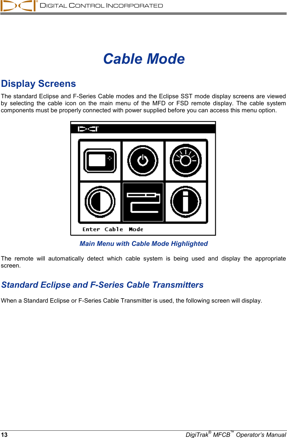
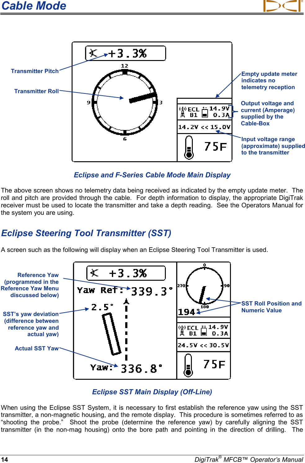
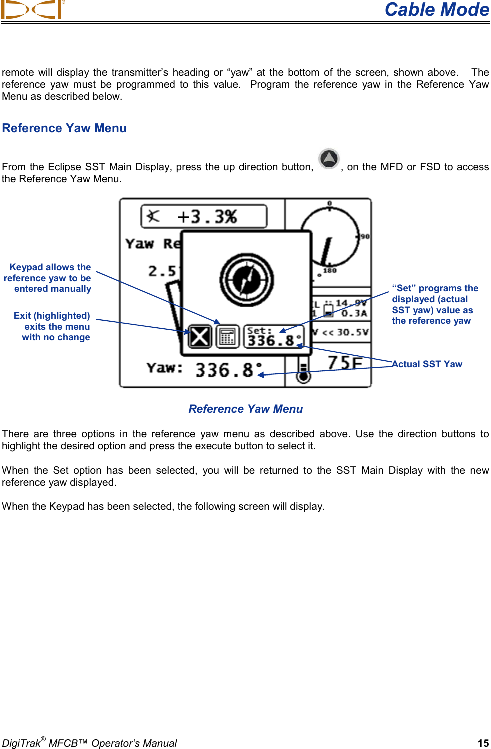
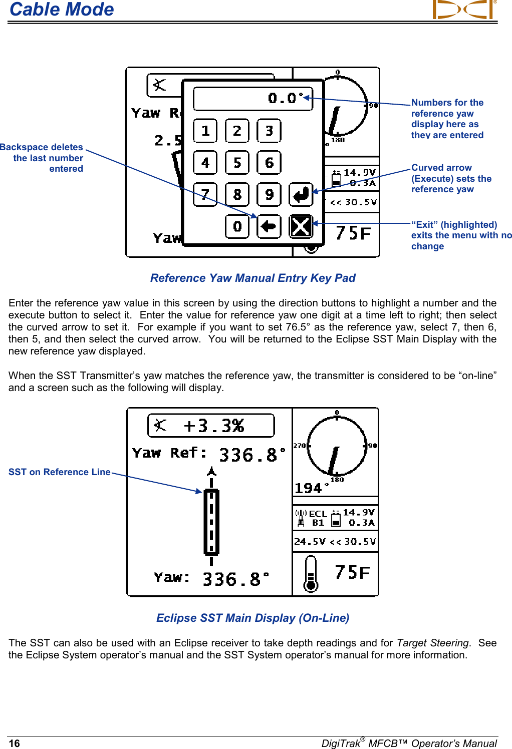
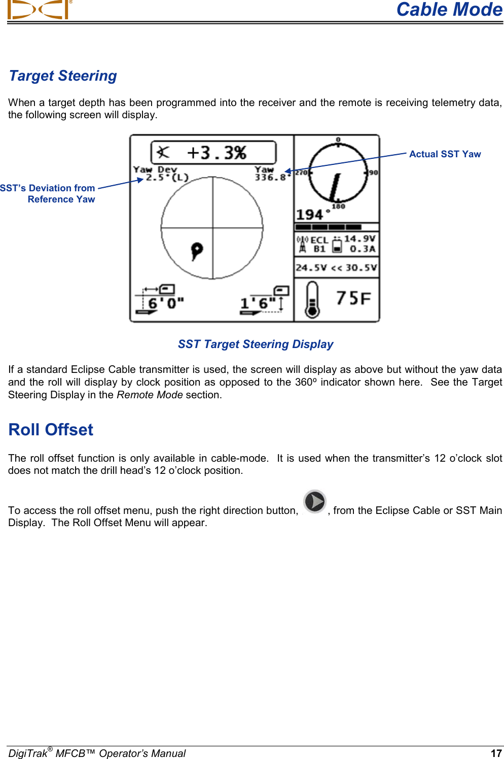
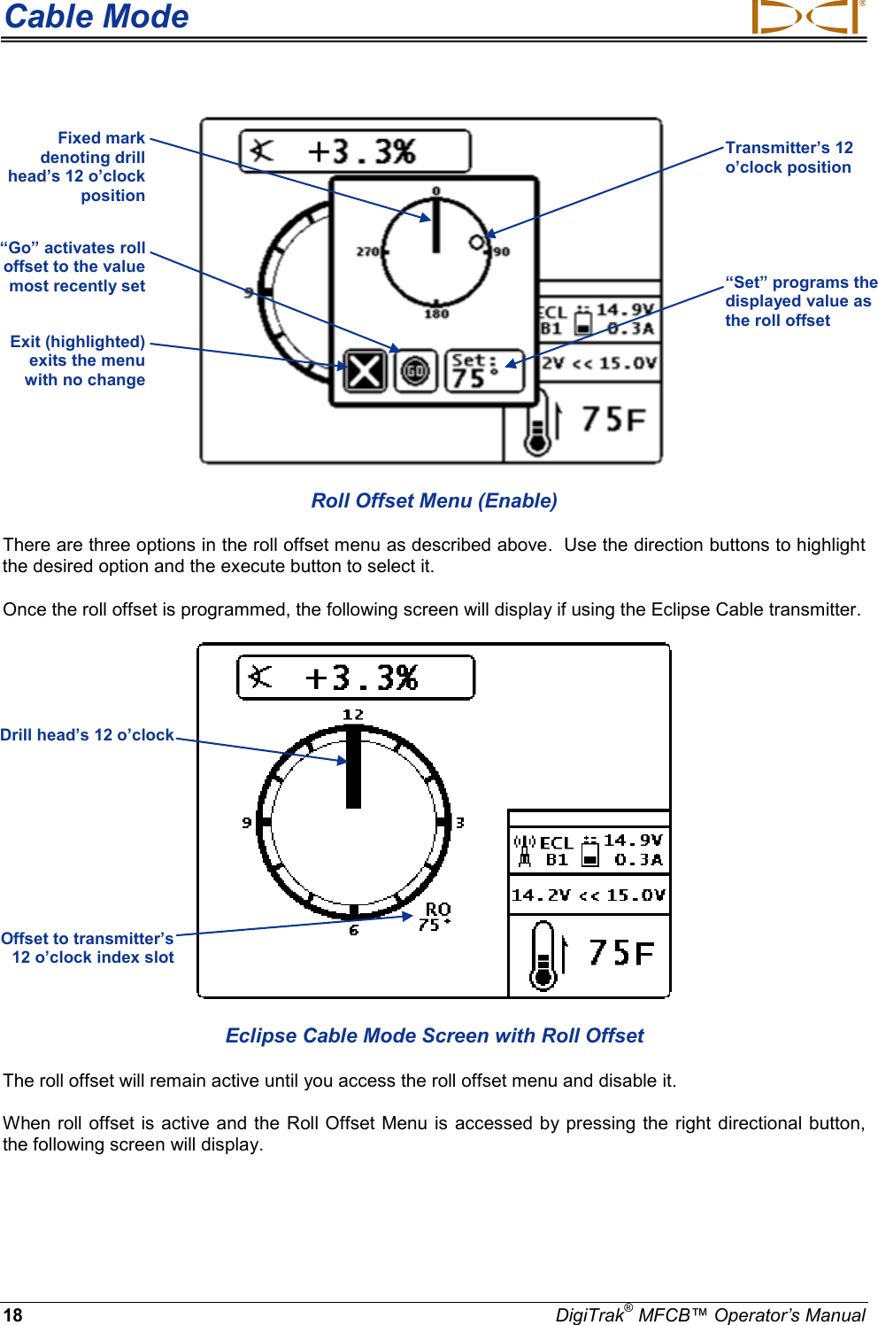
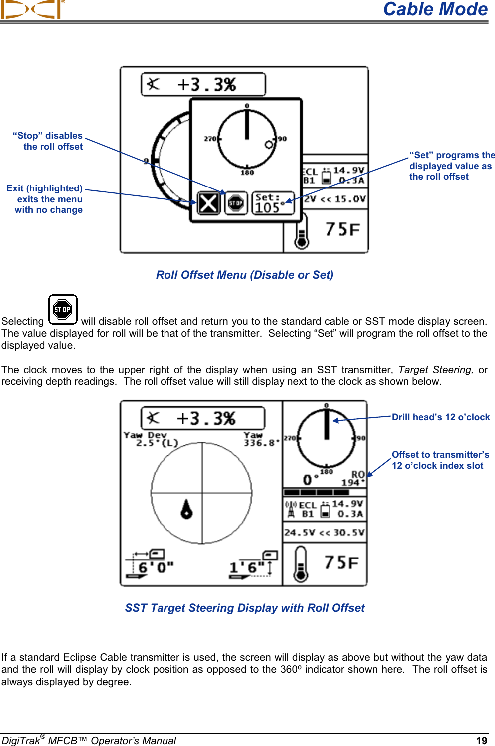
SST Manual
User Manual
Navigation menu
Upload a User Manual
Namespaces
Wiki Guide
HTML
PDF
Info
Views
User Manual
Discussion / Help
Navigation