Digital Control A191920 SST, SST5 User Manual
Digital Control Inc SST, SST5
UserManual.wiki
>
Digital Control
>
A191920 User Manual
>
SST Manual
Contents
1.
User Manual
2.
SST Manual
SST Manual
Navigation menu
Upload a User Manual
Namespaces
Wiki Guide
HTML
PDF
Info
Views
User Manual
Discussion / Help
Navigation

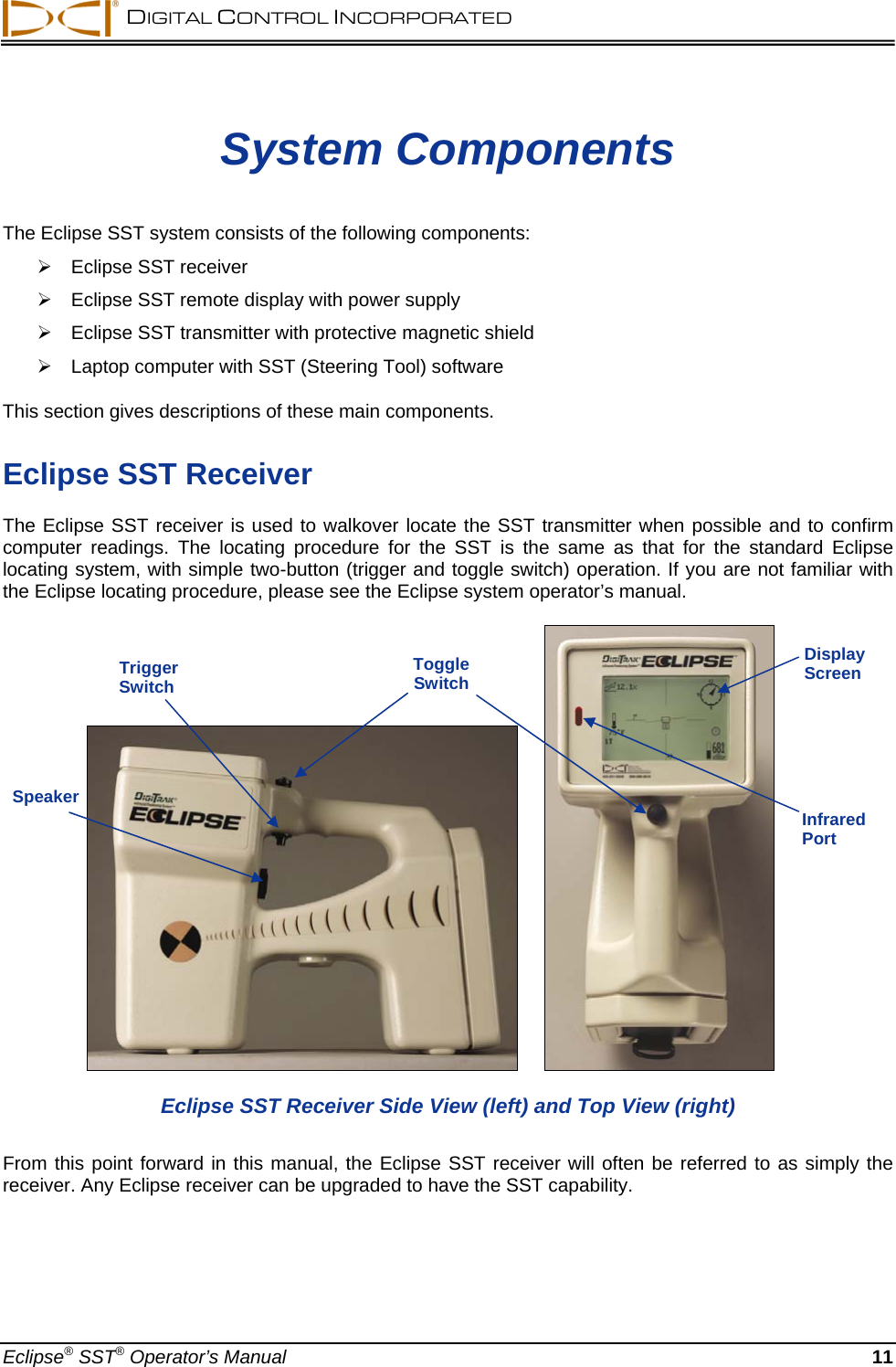
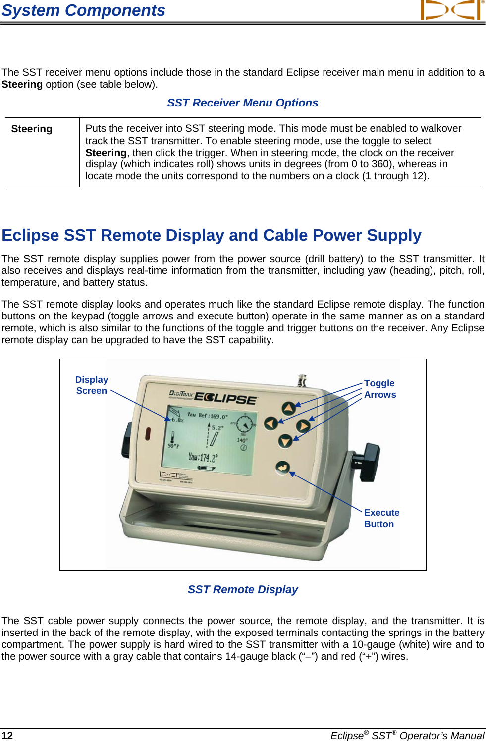
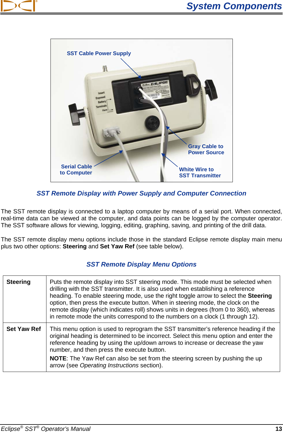
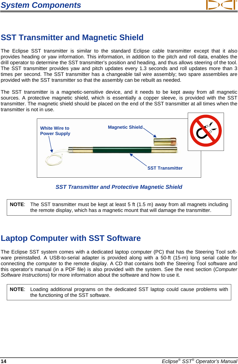

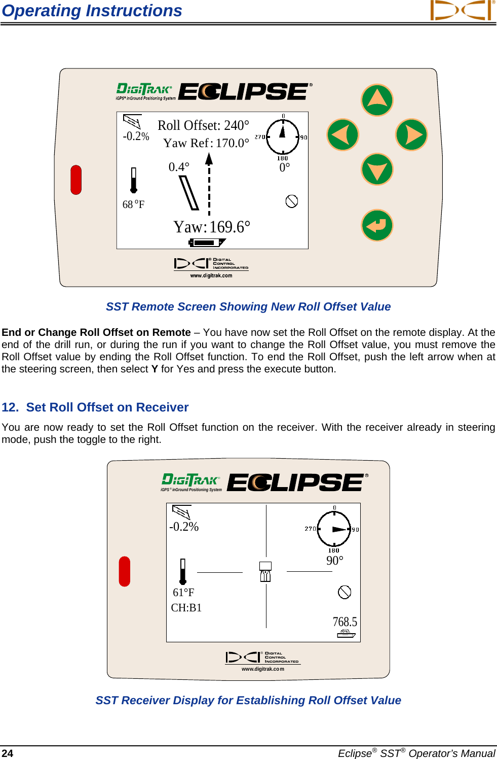
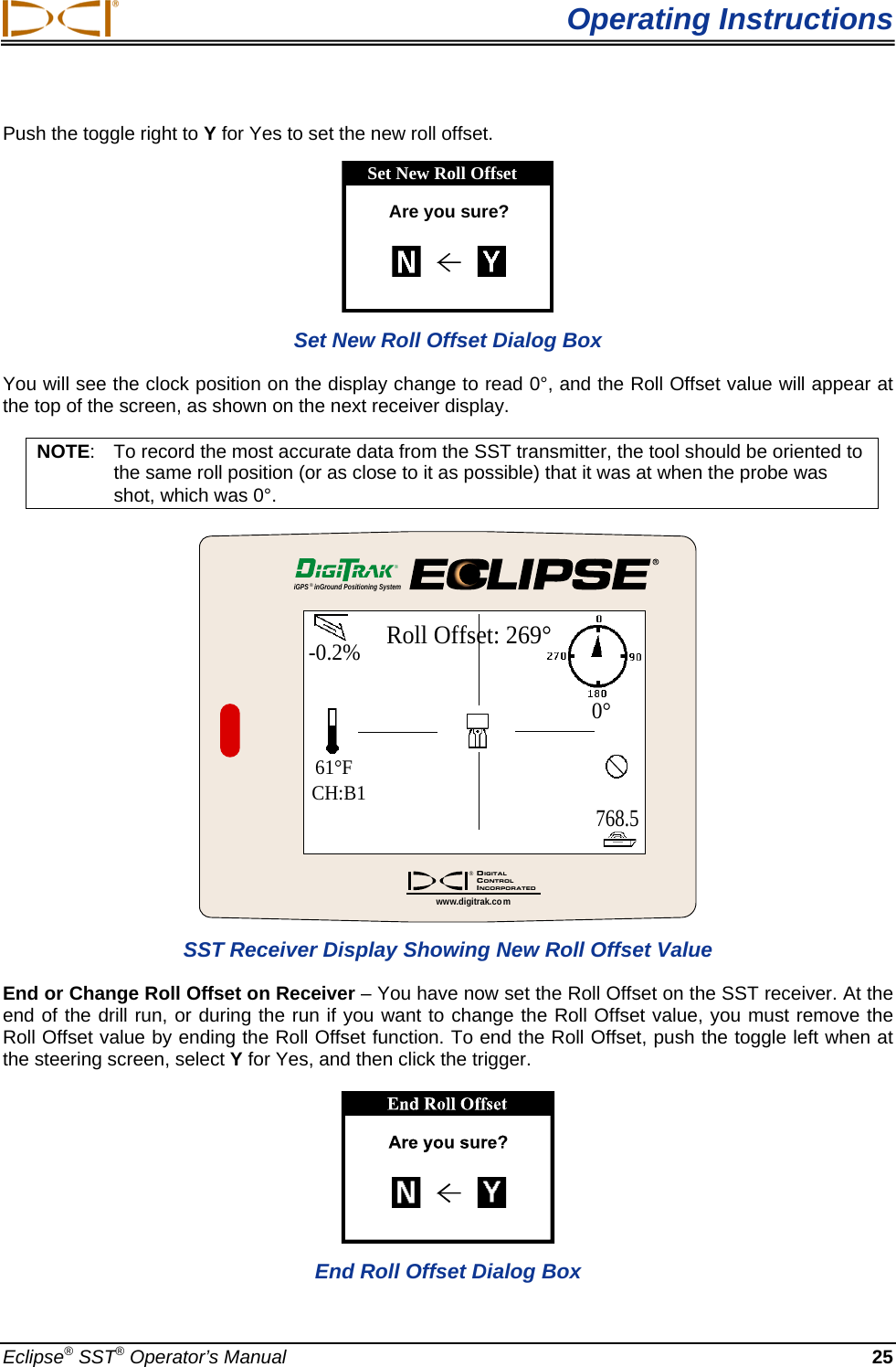
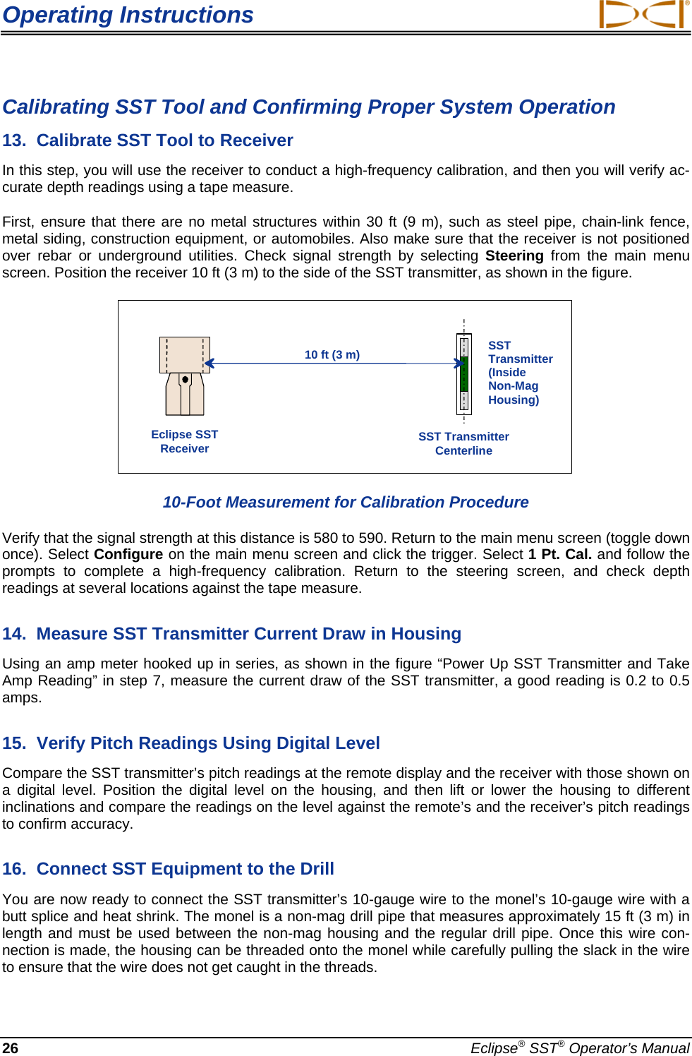
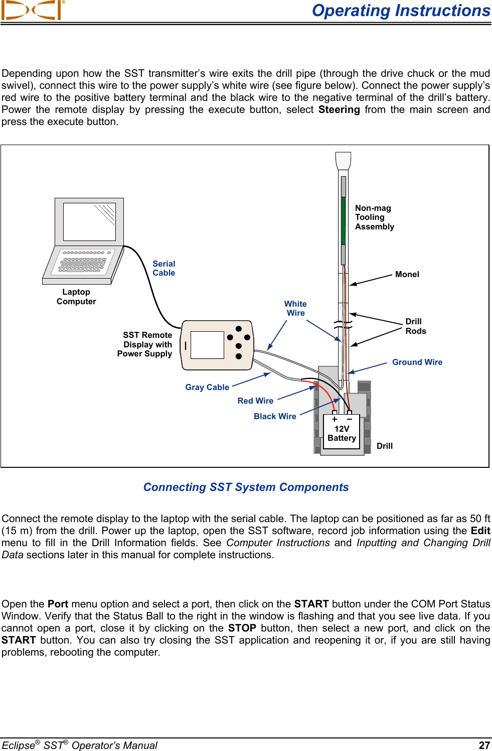
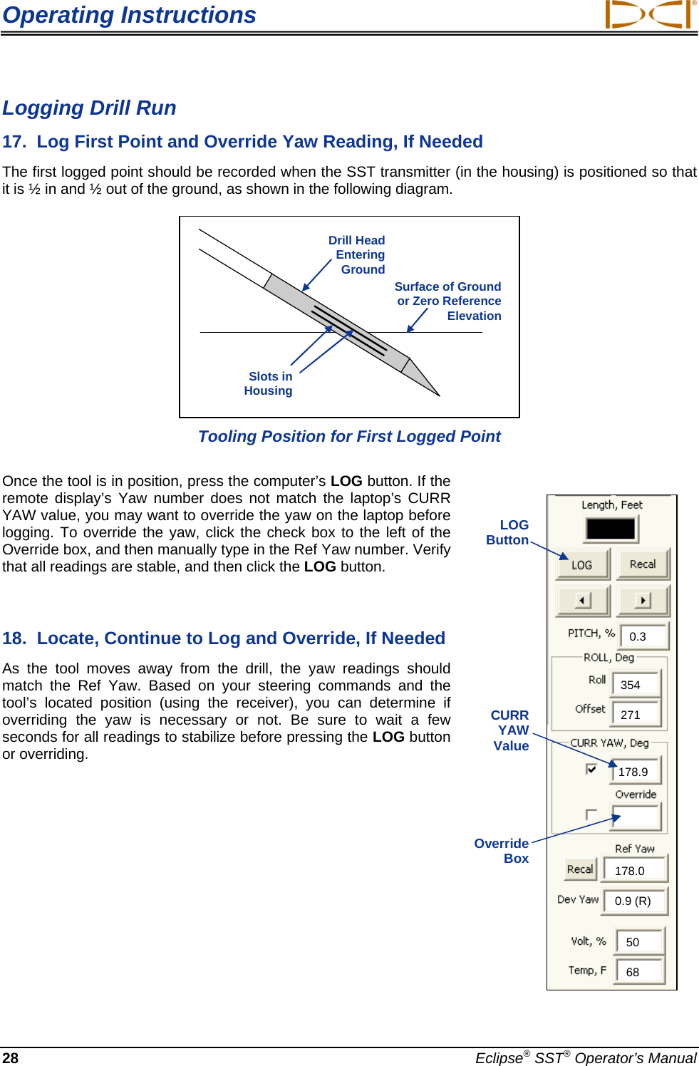
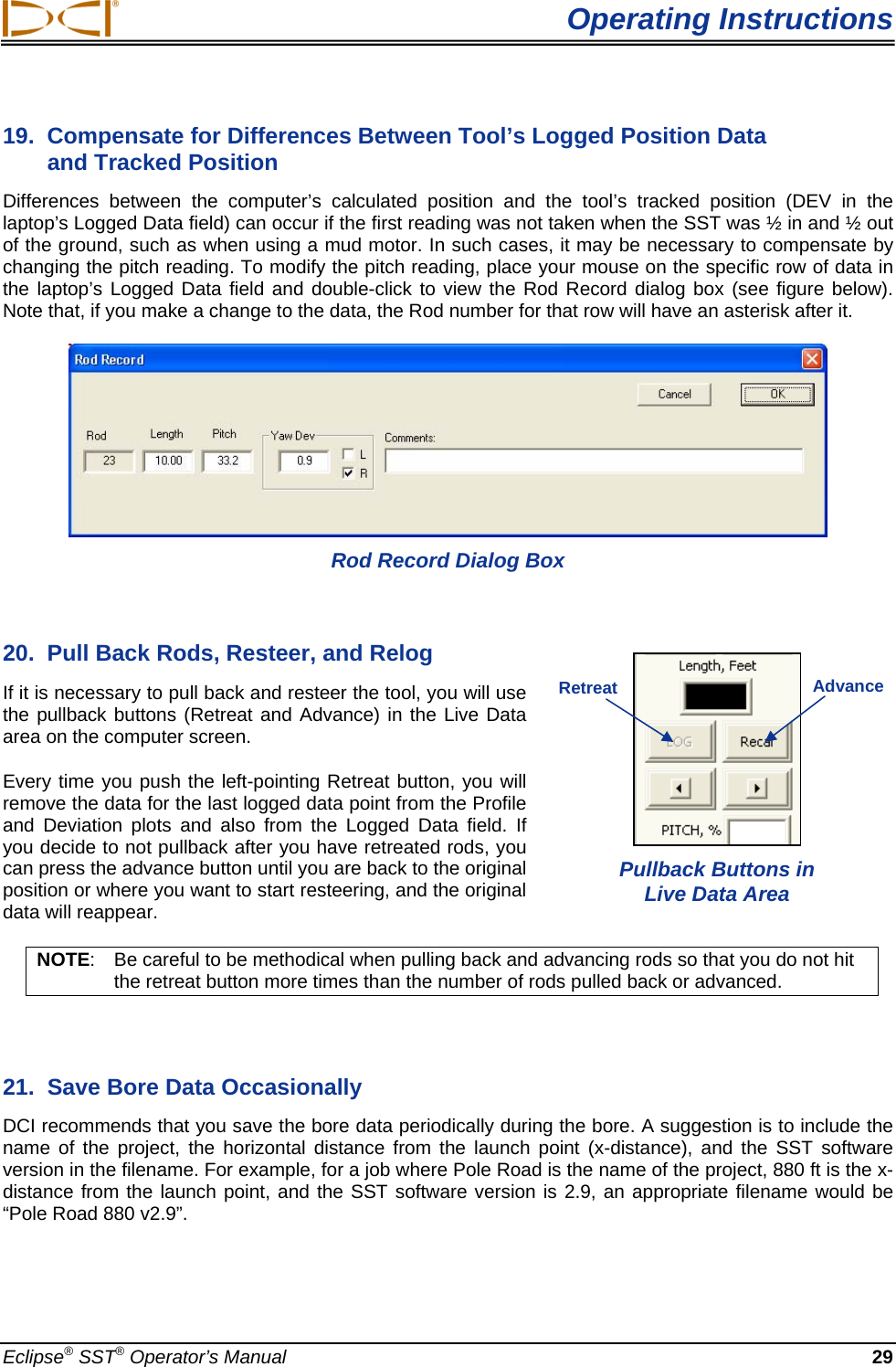
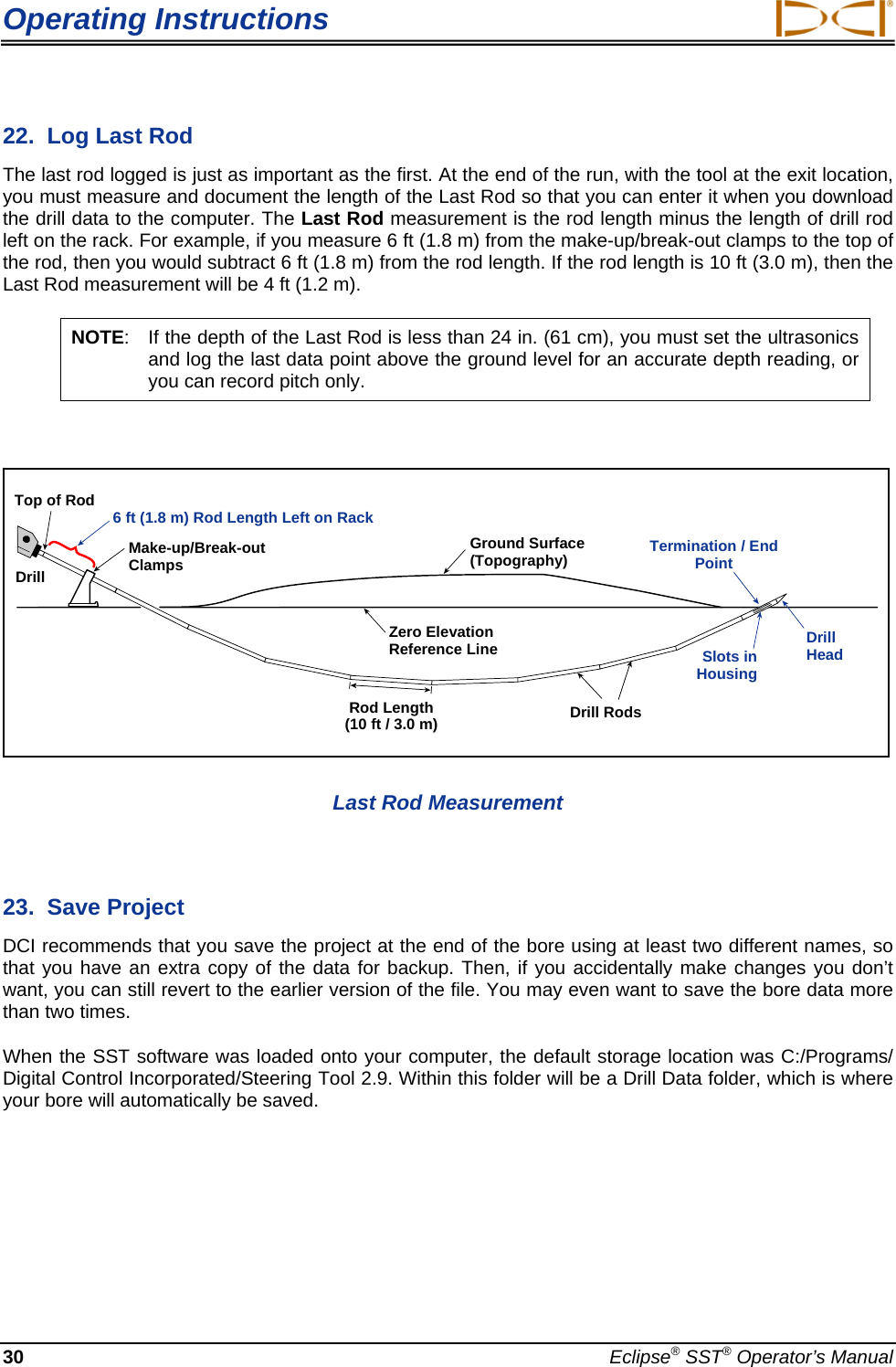
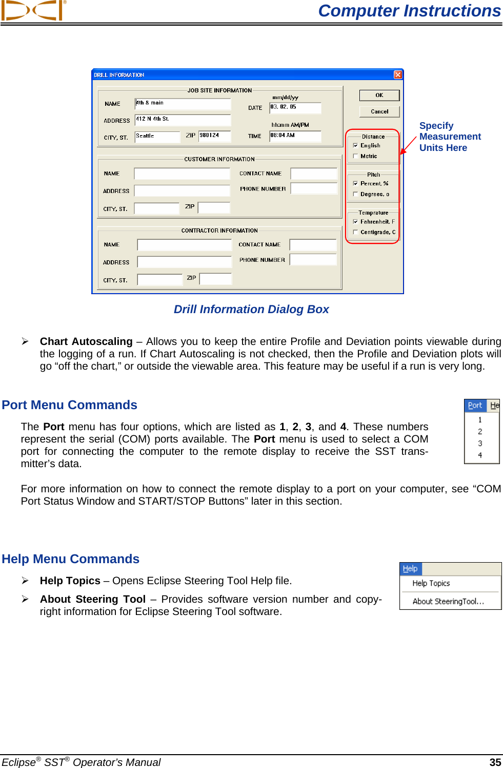
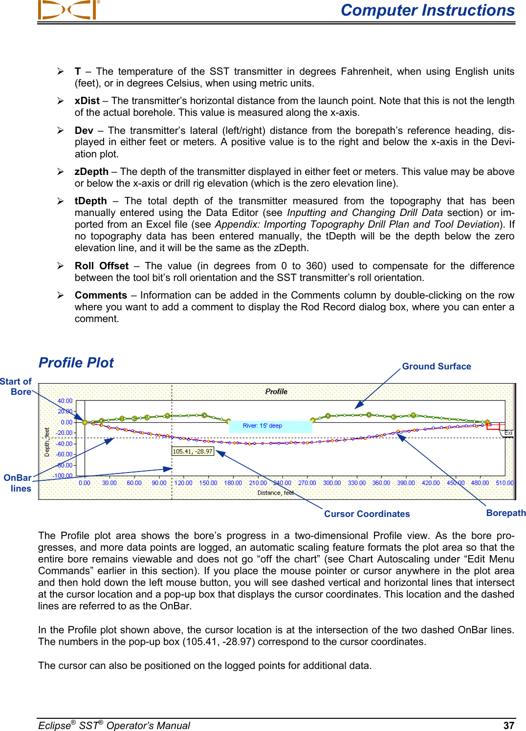
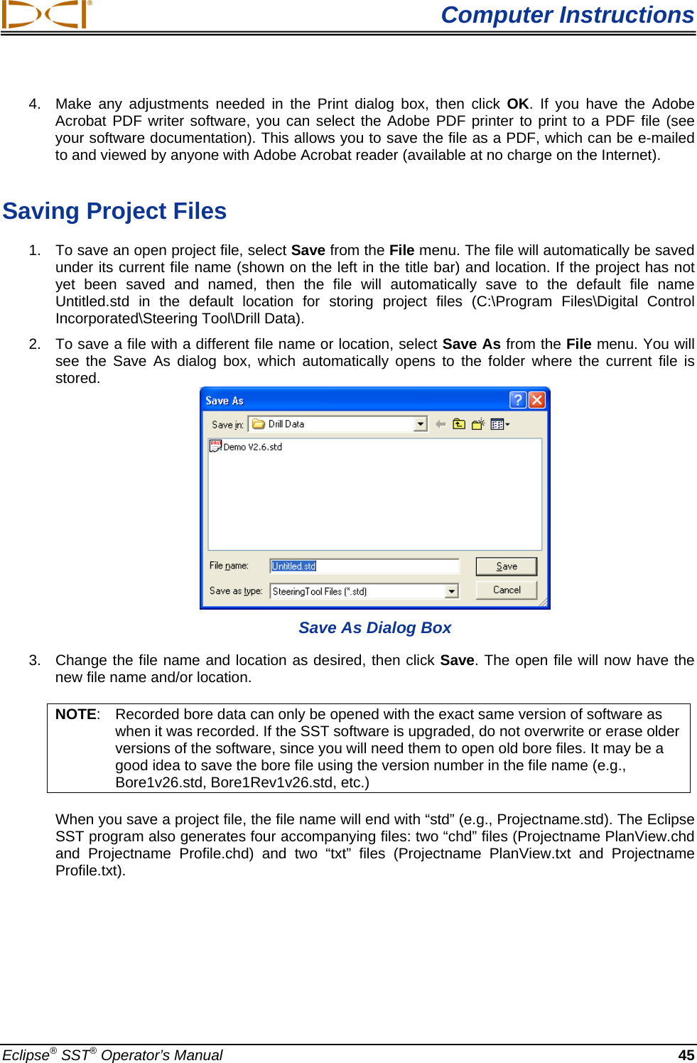
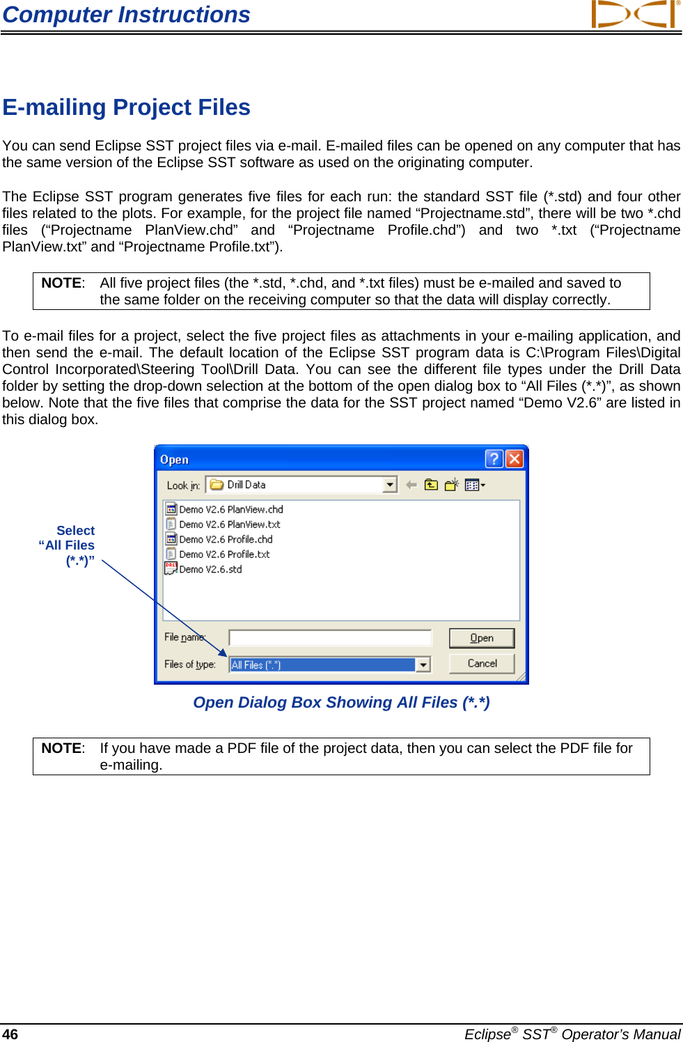
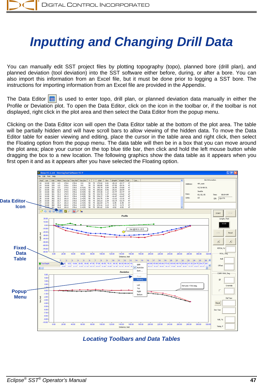
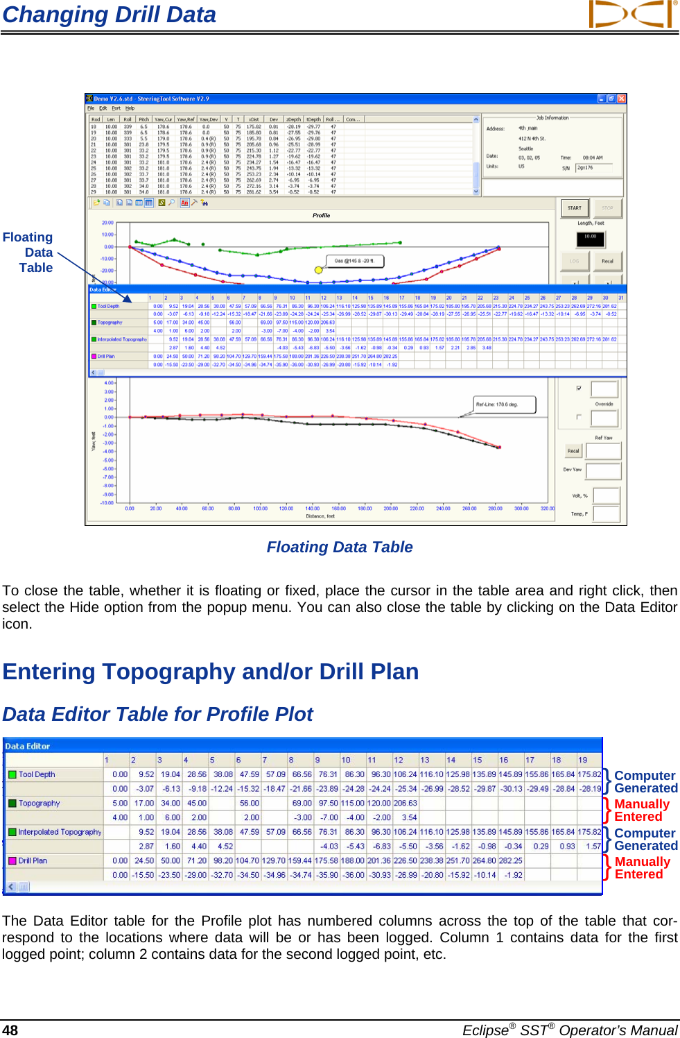
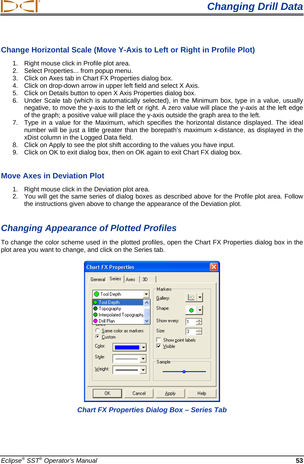
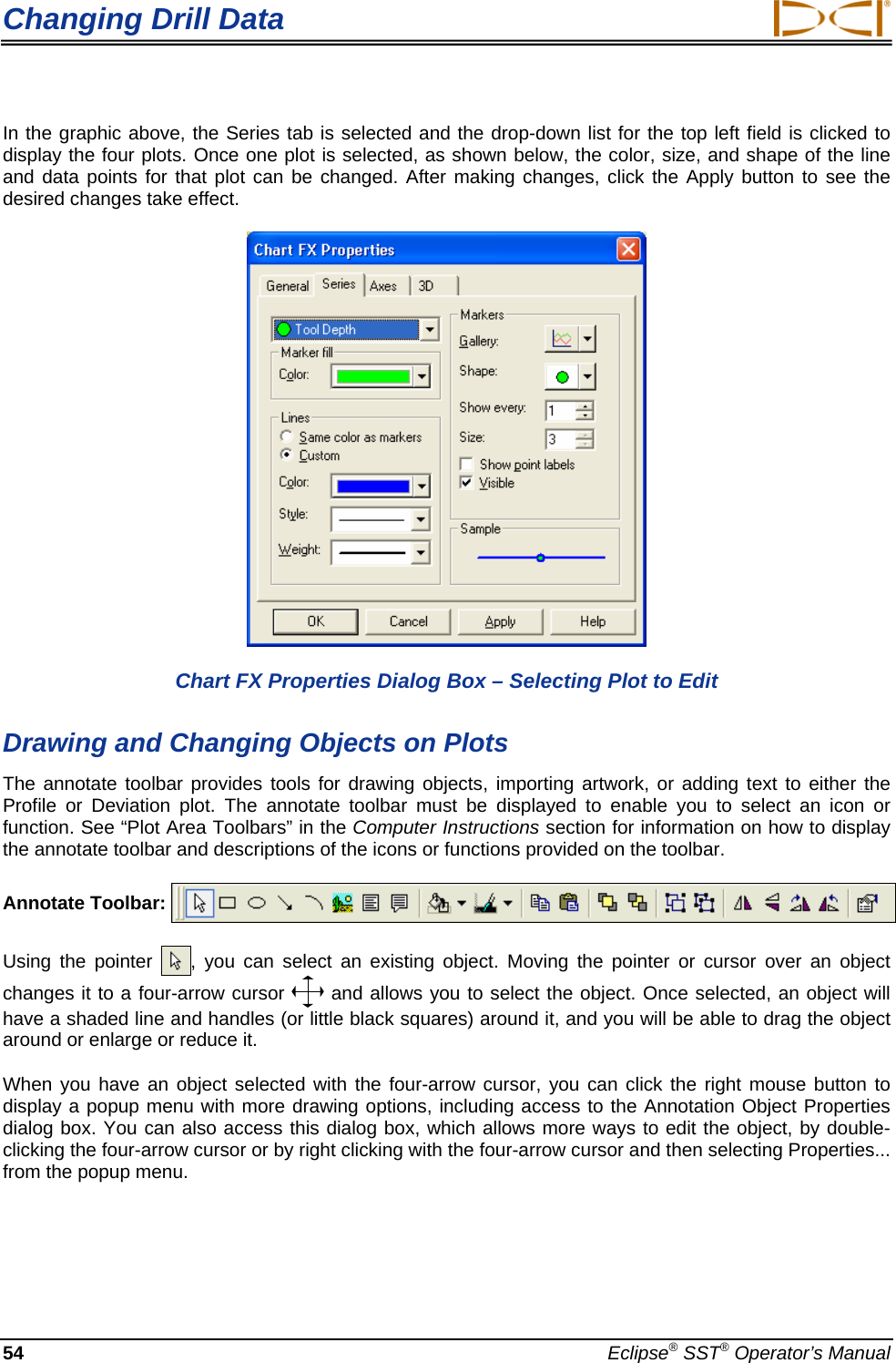
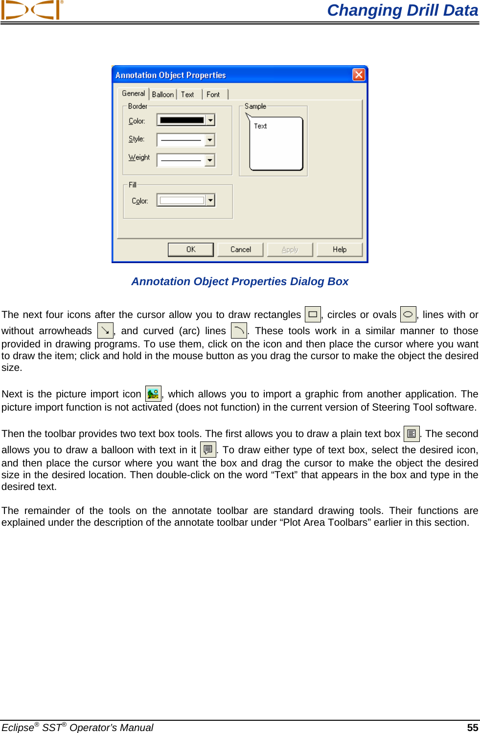
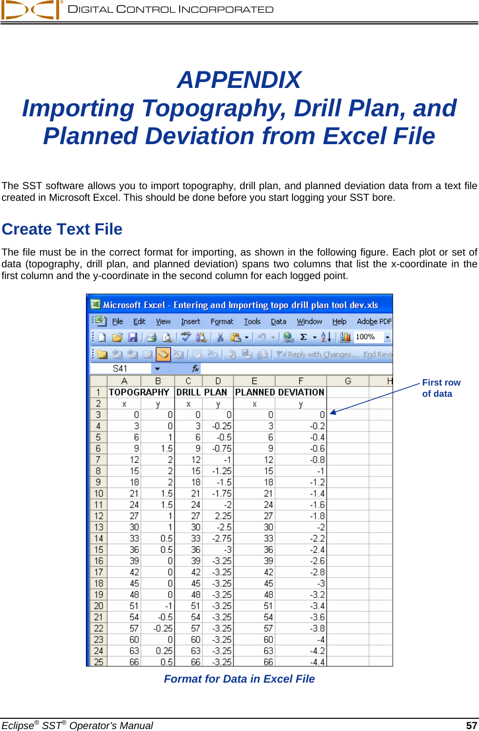
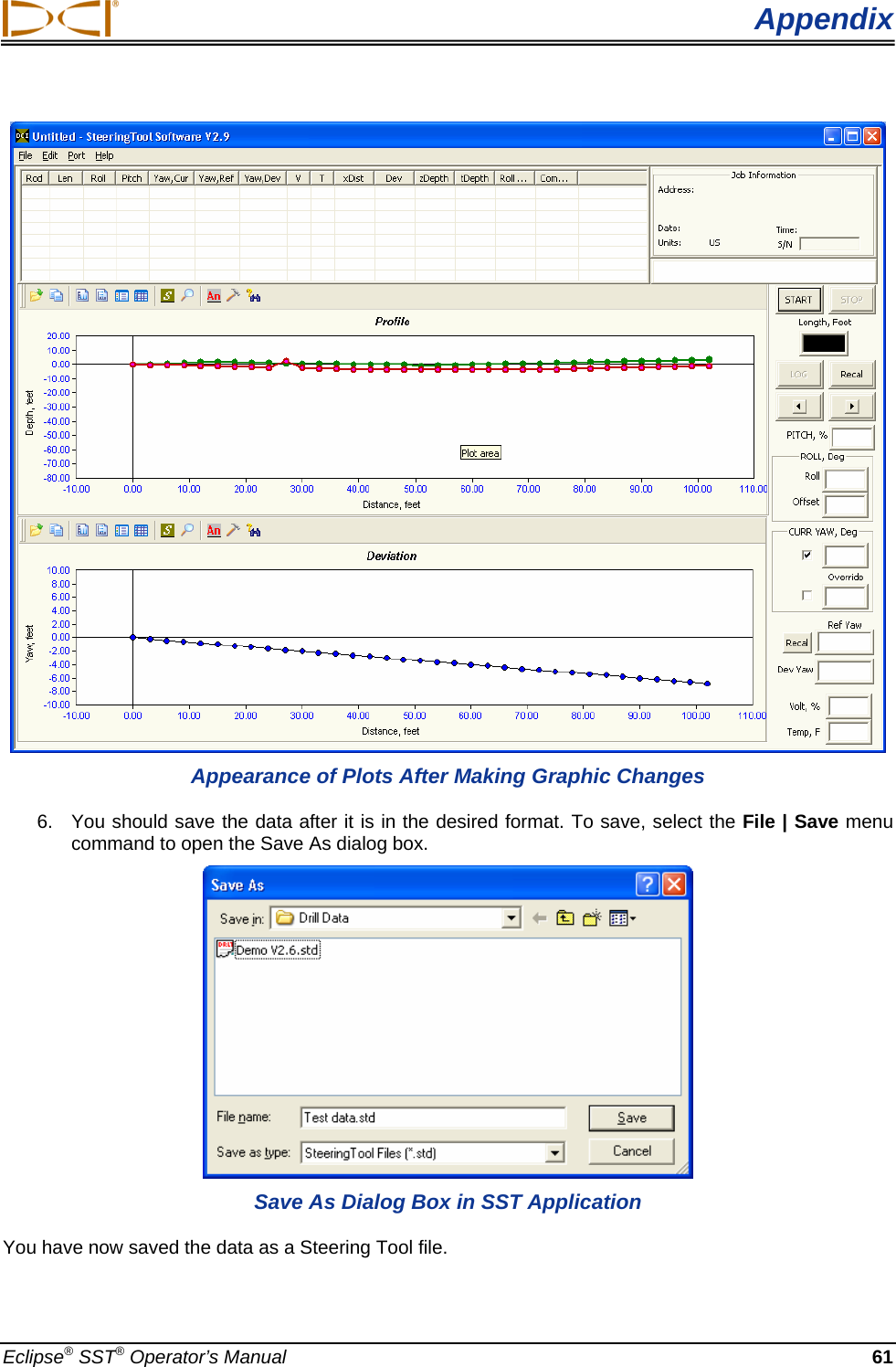
![Computer Instructions Job Information The Job Information field contains information about the project/bore including the address, date, time, pitch units (degrees or percent slope), and depth units (metric or feet). The information is entered in this field by clicking on Edit | Drill Information, and then clicking the checkboxes in the right column of the Drill Information dialog box to indicate your choices for units. If you do not define the depth or pitch units, the default setting of percent and feet will be used. Logged Data The Logged Data field contains 15 columns of rod-by-rod drill data about the bore. The type of data pro-vided under each column heading is described below. ¾ Rod – A sequential listing of data for each logged point or rod. Because the distance between logged points can vary to accommodate different drilling conditions, the number of logged points will not necessarily match the number of actual rods drilled. For example, when considerable pitch changes occur, it is best to log data several times along one or more rods. An asterisk (“*”) will appear next to the rod number if the data for that rod has been changed in the computer. ¾ Len – Typically the length of one drill rod or the distance between data recordings. Len can be changed as needed to compensate for logging more than one data point on a long (30-ft [9-m]) rod or when there are considerable pitch changes, such as at the beginning or the end of a bore. This enables a more accurate calculation of the transmitter’s depth. This value is the same as that appearing in the Length box in the Live Data field (see “Live Data” later in this section). ¾ Roll – The roll position displayed in degrees from 0 to 360, where 12 o’clock is equal to 0°, 3 o’clock is equal to 90°, 6 o’clock is equal to 180°, and 9 o’clock is equal to 270°. ¾ Pitch – The inclination of the transmitter displayed in percent or degree increments. This setting can be changed using the Edit | Drill Information menu option. ¾ Yaw, Cur – The current yaw or heading of the SST transmitter displayed in degrees when the data was logged. ¾ Yaw, Ref – The reference heading of the intended borepath (when you shot the probe). The reference heading can be changed if necessary at the remote display or on the laptop. ¾ Yaw, Dev – The difference between the current yaw and the reference yaw displayed in degrees. Positive deviation is to the right and negative deviation is to the left of the reference yaw. ¾ V – The status of the above-ground battery powering the SST transmitter in percent of power remaining. A low battery has 12V or less remaining; a full battery has 24V. 36 Eclipse® SST® Operator’s Manual](https://usermanual.wiki/Digital-Control/A191920.SST-Manual/User-Guide-1443484-Page-36.png)