Digital Control A191920 SST, SST5 User Manual
Digital Control Inc SST, SST5
Contents
- 1. User Manual
- 2. SST Manual
SST Manual

®
SST
® Guidance System
Operator’s Manual
DIGITAL
CONTROL
INCORPORATED
DCI Headquarters
19625 62nd Ave. S., Suite B-103
Kent, Washington 98032 USA
Tel 425 251 0559 / 800 288 3610
Fax 253 395 2800
E-mail DCI@digital-control.com
www.digitrak.com
DCI Europe
Kurmainzer Strasse 56
D-97836 Bischbrunn
Germany
Tel +49(0) 9394 990 990
Fax +49(0) 9394 990 999
DCI.Europe@digital-control.com
DCI India
SCO # 259, Sector 44-C
Chandigarh (UT) 160 047
Punjab, India
Tel +91(0) 172 464 0444
Fax +91(0) 172 464 0999
DCI.India@digital-control.com
DCI China
USA Excalibre
2803 Bldg C, 70 Cao Bao Rd
Shanghai P.R.C. 200233
Tel +86(0) 21 6432 5186
Fax +86(0) 21 6432 5187
DCI.China@digital-control.com
DCI Australia
2/9 Frinton Street
Southport, Queensland 4215
Australia
Tel +61(0) 7 5531 4283
Fax +61(0) 7 5531 2617
DCI.Australia@digital-control.com

DIGITAL CONTROL INCORPORATED
3-1200-00-D
© 2003-2008 by Digital Control Incorporated. All rights reserved. February 2008 edition.
Trademarks
The DCI logo, CableLink®, DataLog®, DigiTrak®, Eclipse®, iGPS®, Intuitive®, look-ahead®, SST®, target-in-
the-box®, Target Steering®, and TensiTrak® are U.S. registered trademarks, and DucTrak™, FasTrak™,
LT™, SuperCell™, and TeleLock™ are trademarks of Digital Control Incorporated.
Patents
The DigiTrak® Eclipse® Locating System is covered by one or more of the following U.S. Patents:
5,337,002; 5,633,589; 5,698,981; 5,757,190; 5,764,062; 5,767,678; 5,878,824; 5,914,602; 5,926,025;
5,933,008; 5,990,682; 5,990,683; 6,002,258; 6,005,532; 6,008,651; 6,014,026; 6,035,951; 6,047,783;
6,057,687; 6,079,506; 6,095,260; 6,160,401; 6,232,780; 6,250,402; 6,396,275; 6,417,666; 6,454,023;
6,457,537; 6,496,008; 6,525,538; 6,559,646; 6,653,837; 6,677,768; 6,693,429; 6,727,704; 6,756,783;
6,756,784; 6,768,307; 6,856,135; 6,917,202; 6,954,073; 6,975,119; 7,015,697; 7,049,820; 7,061,244.
Sale of a DigiTrak® Eclipse® Receiver does not convey a license under any patents covering the
DigiTrak® Eclipse® Transmitter or underground drill housing. Other patents pending.
Limited Warranty
All products manufactured and sold by Digital Control Incorporated (DCI) are subject to the terms of a
Limited Warranty. A copy of the Limited Warranty is included with this manual along with your DigiTrak®
Eclipse® SST® Guidance System; it can also be obtained by contacting DCI Customer Service, 800-288-
3610 or 425-251-0559, or by connecting to DCI's web site, www.digitrak.com.
Important Notice
All statements, technical information, and recommendations related to the products of DCI are based on
information believed to be reliable, but the accuracy or completeness thereof is not warranted. Before
utilizing any DCI product, the user should determine the suitability of the product for its intended use. All
statements herein refer to DCI products as delivered by DCI and do not apply to any user customizations
not authorized by DCI nor to any third-party products. Nothing herein shall constitute any warranty by DCI
nor will anything herein be deemed to modify the terms of DCI’s existing Limited Warranty applicable to all
DCI products.
FCC Compliance Statement
This equipment has been tested and found to comply with the limits for a Class B digital device, pursuant
to Part 15 of the Rules of the Federal Communications Commission. These limits are designed to provide
reasonable protection against harmful interference in a horizontal directional drilling installation. This
equipment generates, uses, and can radiate radio frequency energy and, if not installed and used in
accordance with the instructions, may cause harmful interference to radio communications or inaccurate
readings on your DCI locating equipment. However, there is no guarantee that interference will not occur
in a particular installation. If this equipment does cause harmful interference to radio or television recep-
tion, which can be determined by turning the equipment off and on, the user is encouraged to try to
correct the interference by one or more of the following measures:
¾ Reorient or relocate the DigiTrak® Eclipse® Receiver.
¾ Increase the separation between the problematic equipment and the DigiTrak® Eclipse® Receiver.
¾ Connect the equipment into an outlet on a different circuit.
¾ Consult the dealer for help.
Changes or modifications to the DCI equipment not expressly approved and carried out by DCI will void
the user’s Limited Warranty and the FCC’s authorization to operate the equipment.
2 Eclipse® SST® Operator’s Manual

DIGITAL CONTROL INCORPORATED
Table of Contents
SAFETY PRECAUTIONS AND WARNINGS................................................................................................5
INTRODUCTION...........................................................................................................................................7
SYSTEM COMPONENTS...........................................................................................................................11
Eclipse SST Receiver...........................................................................................................................11
Eclipse SST Remote Display and Cable Power Supply.......................................................................12
SST Transmitter and Magnetic Shield..................................................................................................14
Laptop Computer with SST Software ...................................................................................................14
Non-DCI Components That Will Be Needed........................................................................................15
STARTUP AND OPERATING INSTRUCTIONS ........................................................................................17
SST Operating Procedure ....................................................................................................................17
Setting Up SST Laptop ..................................................................................................................17
1. Plotting Topography, Drill Plan, and Planned Deviation ....................................................17
Setting Up Equipment and Site......................................................................................................17
2. Establish Borepath Reference Line and Mark Borepath....................................................17
3. Assemble and Torque-up Non-Magnetic Housing to Non-Mag Tool .................................17
4. Align Drill to Marked Borepath............................................................................................18
5. Position and Align Non-mag Tooling Assembly onto Marked Borepath ............................18
6. Stage SST Equipment and Power Sources Adjacent to Tooling Assembly.......................19
7. Power Up Eclipse SST Equipment.....................................................................................20
8. Measure SST Transmitter Current Draw............................................................................21
9. Install SST Transmitter into Aligned Non-mag Tooling Assembly......................................21
Setting Reference Heading (Ref Yaw) and Roll Offset..................................................................21
10. Set Ref Yaw – Shoot Probe..............................................................................................21
11. Set Roll Offset on Remote (if needed) .............................................................................23
12. Set Roll Offset on Receiver ..............................................................................................24
Calibrating SST Tool and Confirming Proper System Operation ..................................................26
13. Calibrate SST Tool to Receiver........................................................................................26
14. Measure SST Transmitter Current Draw in Housing........................................................26
15. Verify Pitch Readings Using Digital Level ........................................................................26
16. Connect SST Equipment to the Drill.................................................................................26
Logging Drill Run............................................................................................................................28
17. Log First Point and Override Yaw Reading, If Needed ....................................................28
18. Locate, Continue to Log and Override, If Needed............................................................28
19. Compensate for Differences Between Tool’s Logged Position Data
and Tracked Position........................................................................................................29
20. Pull Back Rods, Resteer, and Relog................................................................................29
21. Save Bore Data Occasionally...........................................................................................29
22. Log Last Rod ....................................................................................................................30
23. Save Project .....................................................................................................................30
Summary of Basic Operating Procedure..............................................................................................31
Eclipse® SST® Operator’s Manual 3

DIGITAL CONTROL INCORPORATED
Table of Contents (Cont.)
COMPUTER SOFTWARE INSTRUCTIONS..............................................................................................33
Starting Steering Tool Program............................................................................................................33
Menu Bar........................................................................................................................................34
File Menu Commands .............................................................................................................34
Edit Menu Commands.............................................................................................................34
Port Menu Commands.............................................................................................................35
Help Menu Commands............................................................................................................35
Job Information ..............................................................................................................................36
Logged Data...................................................................................................................................36
Profile Plot......................................................................................................................................37
Deviation Plot.................................................................................................................................38
Plot Area Toolbars .........................................................................................................................38
Standard Toolbar.....................................................................................................................39
Annotate Toolbar.....................................................................................................................40
COM Port Status Window and START/STOP Buttons.................................................................41
Live Data........................................................................................................................................41
Opening Project Files ...........................................................................................................................43
Printing and Previewing Project Files...................................................................................................43
Saving Project Files..............................................................................................................................45
E-mailing Project Files..........................................................................................................................46
INPUTTING AND CHANGING DRILL DATA..............................................................................................47
Entering Topography and/or Drill Plan .................................................................................................48
Data Editor Table for Profile Plot ...................................................................................................48
Entering or Changing Topography and Drill Plan Data in Profile Table .......................................49
Entering Tool’s Planned Deviation .......................................................................................................50
Data Editor Table for Deviation Plot...............................................................................................50
Naming Blank Field for Deviation Plot ...........................................................................................50
Entering or Changing Data for Planned Deviation Plot..................................................................50
Graphing Options .................................................................................................................................51
Changing Appearance and Location of X and Y Axes...................................................................51
Change Vertical Scale (Move X-Axis Up or Down in Profile Plot)...........................................52
Change Horizontal Scale (Move Y-Axis to Left or Right in Profile Plot)..................................53
Move Axes in Deviation Plot....................................................................................................53
Changing Appearance of Plotted Profiles......................................................................................53
Drawing and Changing Objects on Plots .......................................................................................54
APPENDIX: IMPORTING TOPOGRAPHY, DRILL PLAN, AND
PLANNED DEVIATION FROM EXCEL FILE..............................................................................................57
Create Text File ....................................................................................................................................57
Save Text File.......................................................................................................................................58
Import Text File into SST Software.......................................................................................................59
LIMITED WARRANTY
4 Eclipse® SST® Operator’s Manual
DIGITAL CONTROL INCORPORATED
Safety Precautions
and Warnings
Important Note: All operators must read and understand the following Safety Precautions and
Warnings and must review this DigiTrak® Eclipse® SST® Guidance System Operator’s Manual
as well as the DigiTrak® Eclipse® inGround Positioning System Operator’s Manual before using
this system.
1 Serious injury and death can result if underground drilling equipment makes contact
with an underground utility such as a high-voltage electrical cable or a natural gas
line.
 Substantial property damage and liability can result if underground drilling equipment
makes contact with an underground utility such as a telephone, cable TV, fiber-optic,
water, or sewer line.
Work slowdowns and cost overruns can occur if drilling operators do not use the
drilling or locating equipment correctly to obtain proper performance.
¾ Directional drilling operators MUST at all times:
y Understand the safe and proper operation of drilling and locating equipment, including the
use of ground mats and proper grounding procedures.
y Ensure that all underground utilities have been located, exposed, and marked accurately
prior to drilling.
y Wear protective safety clothing such as dielectric boots, gloves, hard-hats, high-visibility
vests and safety glasses.
y Locate and track the drill head accurately and correctly during drilling.
y Comply with state and local governmental regulations (e.g., OSHA).
y Follow all other safety procedures.
¾ The DigiTrak Eclipse SST system cannot be used to locate utilities.
¾ Continued exposure to heat, due to frictional heating of the drill head, can cause inaccurate
depth to be displayed and may permanently damage the transmitter.
0 The DigiTrak Eclipse equipment is not explosion-proof and should never be used
near flammable or explosive substances.
Eclipse® SST® Operator’s Manual 5

DIGITAL CONTROL INCORPORATED
Safety Precautions
and Warnings (Cont.)
¾ Prior to the start of each drilling run, test the DigiTrak Eclipse SST system to confirm that it is
operating properly and check that it is providing accurate drill head location and heading
information and accurate drill head depth, pitch, and roll information with the transmitter inside
the drill head.
¾ During drilling, readings will not be accurate unless:
y The Eclipse SST receiver has been properly calibrated and the calibration has been checked
for accuracy so that the receiver shows the correct depth.
y The drill head has been located correctly and accurately and the receiver is directly above
and parallel to the transmitter in the tool underground or above the front locate point (FLP).
y The receiver height-above-ground or ultrasonic distance has been set correctly.
y The SST transmitter remains at a distance of at least 15 ft (4.6 m) from any metal or metallic
objects.
¾ Interference can cause inaccuracies in the measurement of depth and loss of pitch, roll, or the
transmitter’s location or heading.
y Sources of interference include but are not limited to traffic signal loops, invisible dog fences,
cable TV, power lines, fiber-trace lines, metal structures, cathodic protection, telephone lines,
cell phones, transmission towers, conductive earth, salt water, rebar, radio frequencies, and
other unknown sources of interference.
y Interference with the operation of the remote display may also occur from other sources
operating nearby on the same frequency, such as car rental agencies using their remote
check-in modules, other directional drilling locating equipment, etc.
¾ Carefully review this operator’s manual and be sure that you always operate the DigiTrak Eclipse
SST system properly to obtain accurate depth, pitch, roll, yaw, and locate points. If you have any
questions about the operation of the DigiTrak Eclipse SST System, please call DCI’s Customer
Service Department at 425-251-0559 or 800-288-3610.
REMEMBER
If you are having difficulty on the job, call DCI (425-251-0559 or
800-288-3610) and we’ll attempt to help you solve the problem.
6 Eclipse® SST® Operator’s Manual
DIGITAL CONTROL INCORPORATED
Introduction
DigiTrak® Eclipse® SST® Guidance System
The DigiTrak® Eclipse® SST® Guidance System, which is designed for tough horizontal directional drilling
(HDD) projects, provides real-time tool information that enables accurate steering of the drill head. The
system, also referred to as the Steering Tool, displays and records the following types of data:
¾ Compass heading (in tenths of a degree)
¾ Depth (in feet or meters)
¾ Lateral deviation
¾ Pitch (in tenths of a percent or in tenths of a degree, with updates every 1.3 seconds)
¾ Roll (in degrees, from 0 to 360, with updates 3 times per second)
¾ Temperature (in degrees Fahrenheit or Celsius)
The data is shown in real time to the drill operator on the remote display via the wireline connection. Real-
time data is also displayed on the laptop computer, which can be located up to 50 ft (15 m) away from the
remote display. The roll/pitch signal and depth signal, along with locate points, are also transmitted from
the SST transmitter for overhead locating using the receiver. DCI recommends that you use a combina-
tion of walkover and non-walkover locating whenever possible to increase the capabilities and accuracy
of the SST system.
Use of the SST system requires special non-magnetic downhole tooling, including a non-mag housing
and a non-mag 15-ft (3-m) length of drill pipe called a monel. If a mud motor is required, a second monel
will be used between the non-mag housing and the motor or bent sub.
The SST system is designed for jobs where walkover locating may not be an option, such as crossing
under a river or highway. The large amount of drill data that the system records enables reliable steering.
The system can also be used on projects where walkover locating is an option. In these cases, the SST
Eclipse® SST® Operator’s Manual 7

Introduction
transmitter and special non-magnetic housing are put aside, and the battery-operated Eclipse transmitter
is used with a standard housing. A standard Eclipse system can be upgraded to the Eclipse SST system.
Whether running the Eclipse SST transmitter or the battery-operated Eclipse transmitter, the target-in-the-
box® locating feature and look-ahead® capability enable Intuitive® tracking of the transmitter. The receiver
menu options provide quick verification of mode settings and also the ability to program the intended
position of the transmitter for easier remote steering—this is DCI’s Target Steering® feature.
To further expedite wireline connection time, the SST system can be used with the DigiTrak CableLink®
Connection System. The CableLink system is preinstalled in drill rods so that the electrical connection is
made when the rods are threaded up.
There are pieces of equipment, tooling, and some specialty items required for the operation of the SST
system that are not supplied by DCI. Below is a list of items needed for the operation of the SST system
and to make the wire connections:
Non-magnetic housing for SST transmitter – Contact DCI for information about compatible non-
magnetic housings for the SST transmitter.
Monel (non-magnetic drill rod) approximately 15 ft (3 m) long for use between the non-mag
housing and the first drill rod. A second monel may be required if you are using a mud motor.
Fish tape or device to fish wire through rod
Approximately 20 ft (6 m) of 10-gauge wire
Butt splices for 10/12 gauge wire
Crimper
Heat shrinks
Heat gun
Transit or theodolite
String for string line
Tape measure
12V battery or power supply
Amp meter
Digital level
There are some important terms and procedures that are used specifically with the SST system that you
should understand. These include the following:
¾ Yaw / Azimuth – Heading or direction with respect to the earth’s magnetic field. We use yaw to
refer to the heading of the transmitter with respect to the earth’s North Pole.
¾ Reference Yaw (Ref Yaw) – Heading or direction of the SST transmitter measured when it is
accurately positioned on the surveyed borepath prior to the start of the drill run. The value for the
Ref Yaw is determined at the start of the SST operating procedure.
¾ “Shooting the Probe” – Term commonly used for the procedure of measuring the Ref Yaw using
the SST transmitter (probe).
¾ 360 Degree Roll – Standard HDD walkover systems use a “clock” roll orientation. The SST uses
a 1-degree increment roll sensor where 0° = 12 o’clock, 90° = 3 o’clock, 180° = 6 o’clock, and
270° = 9 o’clock.
¾ Roll Offset – Value used to compensate for the difference between the tool bit’s roll orientation
and the SST transmitter’s roll orientation. This value is needed because the torquing process
usually results in the transmitter's roll position not matching the bit's roll position.
Some terms and techniques used in this manual are considered basic to the Eclipse locating system. If
you have never used the Eclipse system, DCI strongly recommends that you read the operator’s manual
8 Eclipse® SST® Operator’s Manual

Introduction
for the Eclipse locating system (DigiTrak® Eclipse® inGround Positioning System Operator’s Manual)
before you try using the SST system.
NOTE: You must know how to operate the Eclipse locating system prior to operating the
Eclipse SST guidance system.
DCI also recommends that you read the instructions given in this SST system operator’s manual and
familiarize yourself with the various menu screens on your Eclipse SST receiver and remote display
before using the system for a production drill. If you have questions, please call DCI’s Customer Service
Department at 800-288-3610 or 425-251-0559.
This operator’s manual begins by describing the primary system components, including the Eclipse SST
receiver, remote display, power supply, transmitter, and laptop with software. Then it presents the system
startup and operating instructions, which cover the standard procedure for using the SST system. This is
followed by instructions for using the Steering Tool computer software program and then detailed informa-
tion for inputting and changing drill data.
The SST operating procedure is discussed in detail in the Startup and Operating Instructions section of
the manual. The full procedure consists of the following actions:
¾ Setting Up SST Laptop
1. Plotting topography, drill plan, and planned deviation
¾ Setting Up Equipment and Site
2. Establish borepath reference line and mark borepath.
3. Assemble and torque up non-magnetic housing to non-mag tool.
4. Align drill to marked borepath.
5. Position and align non-mag tooling assembly onto marked borepath.
6. Stage SST equipment and power sources adjacent to tooling assembly.
7. Power up Eclipse SST equipment.
8. Measure SST transmitter current draw.
9. Install SST transmitter into aligned non-mag tooling assembly.
¾ Setting Reference Heading (Ref Yaw) and Roll Offset
10. Set Ref Yaw and shoot the probe.
11. Set roll offset on remote display (if needed).
12. Set roll offset on receiver.
¾ Calibrating SST Tool and Confirming Proper System Operation
13. Calibrate SST tool to receiver.
14. Measure SST transmitter current draw in housing.
15. Verify pitch readings using digital level.
16. Connect SST equipment to the drill.
¾ Logging Drill Run
17. Log first point and override yaw reading, if needed.
18. Locate, continue to log and override, if needed.
19. Compensate for differences between tool’s logged position data and tracked position.
20. Pull back rods, resteer, and relog.
21. Save bore data occasionally.
22. Log last rod.
23. Save project.
Eclipse® SST® Operator’s Manual 9

Introduction
Notes
10 Eclipse® SST® Operator’s Manual
DIGITAL CONTROL INCORPORATED
System Components
The Eclipse SST system consists of the following components:
¾ Eclipse SST receiver
¾ Eclipse SST remote display with power supply
¾ Eclipse SST transmitter with protective magnetic shield
¾ Laptop computer with SST (Steering Tool) software
This section gives descriptions of these main components.
Eclipse SST Receiver
The Eclipse SST receiver is used to walkover locate the SST transmitter when possible and to confirm
computer readings. The locating procedure for the SST is the same as that for the standard Eclipse
locating system, with simple two-button (trigger and toggle switch) operation. If you are not familiar with
the Eclipse locating procedure, please see the Eclipse system operator’s manual.
Display
Screen
Toggle
Switch
Trigge
r
Switch
Speake
r
Infrared
Port
Eclipse SST Receiver Side View (left) and Top View (right)
From this point forward in this manual, the Eclipse SST receiver will often be referred to as simply the
receiver. Any Eclipse receiver can be upgraded to have the SST capability.
Eclipse® SST® Operator’s Manual 11
System Components
The SST receiver menu options include those in the standard Eclipse receiver main menu in addition to a
Steering option (see table below).
SST Receiver Menu Options
Steering Puts the receiver into SST steering mode. This mode must be enabled to walkover
track the SST transmitter. To enable steering mode, use the toggle to select
Steering, then click the trigger. When in steering mode, the clock on the receiver
display (which indicates roll) shows units in degrees (from 0 to 360), whereas in
locate mode the units correspond to the numbers on a clock (1 through 12).
Eclipse SST Remote Display and Cable Power Supply
The SST remote display supplies power from the power source (drill battery) to the SST transmitter. It
also receives and displays real-time information from the transmitter, including yaw (heading), pitch, roll,
temperature, and battery status.
The SST remote display looks and operates much like the standard Eclipse remote display. The function
buttons on the keypad (toggle arrows and execute button) operate in the same manner as on a standard
remote, which is also similar to the functions of the toggle and trigger buttons on the receiver. Any Eclipse
remote display can be upgraded to have the SST capability.
Display
Screen Toggle
Arrows
Execute
Button
SST Remote Display
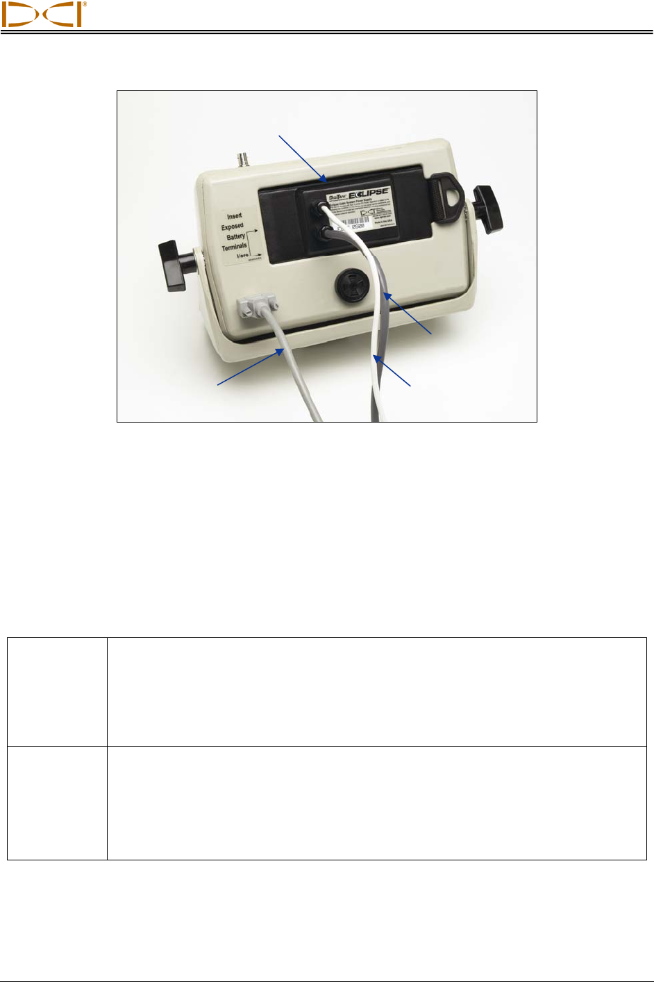
The SST cable power supply connects the power source, the remote display, and the transmitter. It is
inserted in the back of the remote display, with the exposed terminals contacting the springs in the battery
compartment. The power supply is hard wired to the SST transmitter with a 10-gauge (white) wire and to
the power source with a gray cable that contains 14-gauge black (“–”) and red (“+”) wires.
12 Eclipse® SST® Operator’s Manual
System Components
SST Cable Power Supply
Gray Cable to
Power Source
Serial Cable
to Computer White Wire to
SST Transmitter
SST Remote Display with Power Supply and Computer Connection
The SST remote display is connected to a laptop computer by means of a serial port. When connected,
real-time data can be viewed at the computer, and data points can be logged by the computer operator.
The SST software allows for viewing, logging, editing, graphing, saving, and printing of the drill data.
The SST remote display menu options include those in the standard Eclipse remote display main menu
plus two other options: Steering and Set Yaw Ref (see table below).
SST Remote Display Menu Options
Steering Puts the remote display into SST steering mode. This mode must be selected when
drilling with the SST transmitter. It is also used when establishing a reference
heading. To enable steering mode, use the right toggle arrow to select the Steering
option, then press the execute button. When in steering mode, the clock on the
remote display (which indicates roll) shows units in degrees (from 0 to 360), whereas
in remote mode the units correspond to the numbers on a clock (1 through 12).
Set Yaw Ref This menu option is used to reprogram the SST transmitter’s reference heading if the
original heading is determined to be incorrect. Select this menu option and enter the
reference heading by using the up/down arrows to increase or decrease the yaw
number, and then press the execute button.
NOTE: The Yaw Ref can also be set from the steering screen by pushing the up
arrow (see Operating Instructions section).
Eclipse® SST® Operator’s Manual 13
System Components
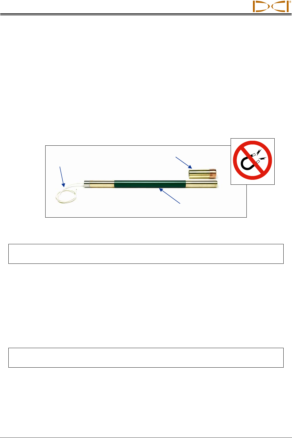
SST Transmitter and Magnetic Shield
The Eclipse SST transmitter is similar to the standard Eclipse cable transmitter except that it also
provides heading or yaw information. This information, in addition to the pitch and roll data, enables the
drill operator to determine the SST transmitter’s position and heading, and thus allows steering of the tool.
The SST transmitter provides yaw and pitch updates every 1.3 seconds and roll updates more than 3
times per second. The SST transmitter has a changeable tail wire assembly; two spare assemblies are
provided with the SST transmitter so that the assembly can be rebuilt as needed.
The SST transmitter is a magnetic-sensitive device, and it needs to be kept away from all magnetic
sources. A protective magnetic shield, which is essentially a copper sleeve, is provided with the SST
transmitter. The magnetic shield should be placed on the end of the SST transmitter at all times when the
transmitter is not in use.
Magnetic Shield
White Wire to
Power Supply
SST Transmitte
r
SST Transmitter and Protective Magnetic Shield
NOTE: The SST transmitter must be kept at least 5 ft (1.5 m) away from all magnets including
the remote display, which has a magnetic mount that will damage the transmitter.
Laptop Computer with SST Software
The Eclipse SST system comes with a dedicated laptop computer (PC) that has the Steering Tool soft-
ware preinstalled. A USB-to-serial adapter is provided along with a 50-ft (15-m) long serial cable for
connecting the computer to the remote display. A CD that contains both the Steering Tool software and
this operator’s manual (in a PDF file) is also provided with the system. See the next section (Computer
Software Instructions) for more information about the software and how to use it.
NOTE: Loading additional programs on the dedicated SST laptop could cause problems with
the functioning of the SST software.
14 Eclipse® SST® Operator’s Manual

System Components
Non-DCI Components That Will Be Needed
There are pieces of equipment, tooling, and some specialty items required for the operation of the SST
system that are not supplied by DCI. Below is a list of items needed for the operation of the SST system
and to make the wire connections:
Non-magnetic housing for SST transmitter
Monel (non-magnetic drill rod) approximately 15 ft (3 m) long for use between the non-mag
housing and the first drill rod. A second monel may be required if you are using a mud motor.
Fish tape or device to fish wire through rod
Approximately 20 ft (6 m) of 10-gauge wire
Butt splices for 10/12 gauge wire
Crimper
Heat shrinks
Heat gun
Transit or theodolite
String for string line
Tape measure
12V battery or power supply
Amp meter
Digital level
Eclipse® SST® Operator’s Manual 15

System Components
Notes
16 Eclipse® SST® Operator’s Manual

DIGITAL CONTROL INCORPORATED
Startup and Operating Instructions
The Eclipse SST system provides information at the remote display and the computer that enables you to
make accurate (reliable) steering decisions. It also logs and saves the drill data.
This section provides detailed operating instructions for using the system. Please read over the procedure
carefully and ensure that you understand all the instructions before you attempt to do it yourself.
Other components that you will need in addition to the SST system components are listed below. These
items are not provided by DCI with the SST system, but they are needed for setting up and operating the
system.
Non-magnetic housing and monel
Surveying equipment (transit or theodolite)
Stakes or string for marking reference line
Butt splices and heat shrinks for wireline connections or DCI CableLink-installed rods
10-gauge wire – approximately 20 ft (6 m) for use in establishing the reference heading
Tools for crimping
12V battery or power supply
Alligator clips and wire nuts to connect appropriate wires to power and ground sources
Tape measure
Digital level
Amp meter
SST Operating Procedure
Setting Up SST Laptop
1. Plotting Topography, Drill Plan, and Planned Deviation
Prior to drilling, you may want to input topographic and/or planned bore information into the SST software.
This information can be input during the drilling/logging process, although it is not recommended unless
you have a dedicated computer operator to ensure correct and accurate input. Instructions for manually
inputting this data are provided in detail later in this manual under the section titled Inputting and
Changing Drill Data.
Setting Up Equipment and Site
2. Establish Borepath Reference Line and Mark Borepath
DCI recommends that you use surveying equipment to establish the borepath. Once, established, mark
the borepath with a string line based off of the survey markers. This reference line will
help in aligning the drill and non-mag tooling assembly to the intended borepath.
3. Assemble and Torque-up Non-Magnetic Housing to Non-Mag Tool
Using the drill rig or other hydraulic torquing wrenches, thread the non-mag housing to the non-mag tool
and torque-up.
Eclipse® SST® Operator’s Manual 17

Operating Instructions
4. Align Drill to Marked Borepath
With the transit positioned at least 10 ft (3 m) ahead of the drill, position the drill so that the transit sights
onto the center point of the drive chuck and/or centerline of the boom. Anchor the drill, and then use the
transit to confirm that the drill is still aligned to the marked borepath; if not, adjust for proper alignment.
Aligning Drill to Marked Borepath
5. Position & Align Non-mag Tooling
Assembly onto Marked Borepath
With the transit still in position but rotated 180°,
place the tooling assembly at least 30 ft (9 m) in
front of the drill, onto the marked borepath so that
it is pointing in the direction of drilling with the tool
or bent sub oriented to 0° (12 o’clock), as shown
in the following photo and sketch. Sight the transit
onto the string line and carefully align the non-
mag assembly to the marked borepath.
Be sure there are no large metallic objects, in-
cluding the drill, within 30 ft (9 m) of the non-mag
assembly.
Aligning Non-Mag Tooling
Assembly to Marked Borepath
18 Eclipse® SST® Operator’s Manual
Operating Instructions
MINIMUM
30-ft (9-m)
NO METAL ZONE
Drill
Centerline
of Boom Centerpoint of
Drive Chuck
Transit
Non-mag Tooling
Assembly with
Bit Oriented at 0°
Surveyed and
Marked Borepath
At Least
30 ft (9 m)
from Tool
to Drill
About 10 ft (3 m)
from Transit
to Drill
SST Job Site Setup
6. Stage SST Equipment and Power Sources Adjacent to Tooling Assembly
In preparation for powering up the Eclipse SST equipment, position the following items adjacent to the
tooling assembly:
Eclipse SST receiver
Eclipse SST remote display
Eclipse SST transmitter
DCI NiCad battery for receiver
DCI power supply
Power source, such as a generator, 12V battery, or additional DCI NiCad battery
Amp meter
NOTE: Keep the remote display with its magnetic mounting bracket at least 5 ft (1.5 m) from
the SST transmitter or damage to the SST transmitter could occur.
Eclipse® SST® Operator’s Manual 19
Operating Instructions
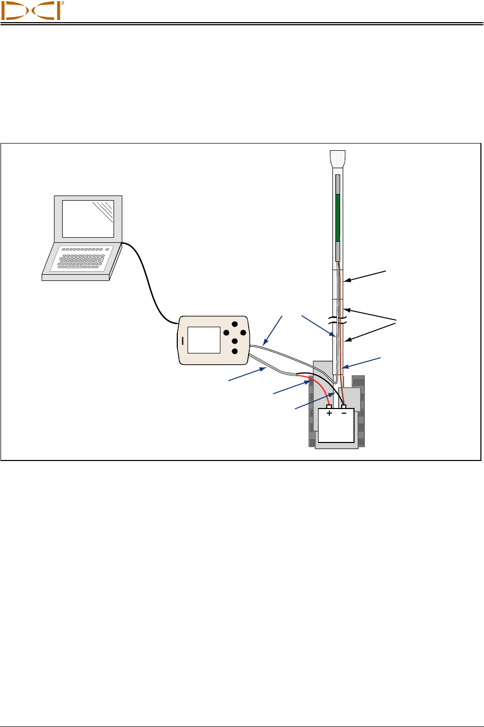
7. Power Up Eclipse SST Equipment
1. Receiver – Install a DCI NiCad battery pack and click the trigger to power up the receiver. Select
Steering from the main menu screen.
2. Remote display – Insert DCI power supply into the back of the remote display. Do not power up
the remote at this time; you will connect the SST to the power supply before powering up the
remote.
3. SST transmitter – Connect the SST transmitter’s wire to the power supply’s white wire. Connect
the black wire (in the gray cable from the power supply) to the negative terminal on the power
source, and connect the red wire to the positive terminal on the power source.
4. Ground the SST transmitter – Connect the power source’s negative terminal to the SST
transmitter’s metal end cap.
5. Power the remote display by pressing the execute button. To view data, select Steering from the
main menu screen and press the execute button.
Verify that you see data on the remote display and the receiver.
Drill
SST
Transmitter
At Least 30 ft (9 m)
from Transmitter
to Drill
Battery
(12V or
DCI NiCad)
SST
Receiver
SST Remote
Display with
Power Supply
Amp
Meter
White Wire
Gray Cable
Black Wire
Red Wire
Ground
Wire
Power Up SST Transmitter and Take Amp Reading
20 Eclipse® SST® Operator’s Manual
Operating Instructions
8. Measure SST Transmitter Current Draw
Using an amp meter hooked up in series as shown in the figure above, measure the current draw of the
SST transmitter—a good reading is approximately 0.2 to 0.5 amps. The current draw will increase as the
distance you drill increases . A normal current draw, for example, at 1500 ft (457 m) is about 0.7 amps. Th
e maximum current draw you should see is approxi-
mately 1 amp.
9. Install SST Transmitter into Aligned Non-mag Tooling Assembly
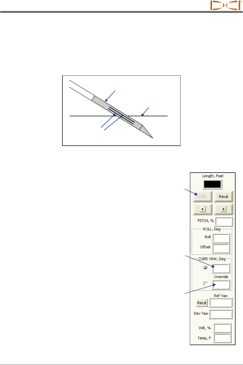
Install the SST transmitter into the aligned non-mag housing (tooling assembly) being sure to completely
seat the SST transmitter’s index slot onto the housing’s internal clocking key; you should not be able to
rotate the SST if it is correctly seated. Disconnect the amp meter, and reconnect the transmitter’s wire to
the DCI power supply’s white wire. Be sure to ground the housing; this is commonly done by cutting a
length of wire and touching one end to a negative battery terminal and the other end to the non-mag
housing.
Setting Reference Heading (Ref Yaw) and Roll Offset
10. Set Ref Yaw – Shoot Probe
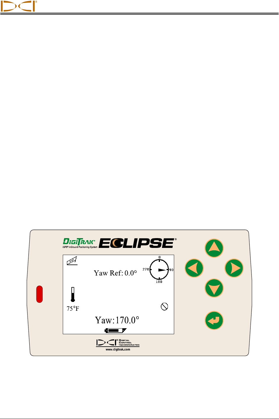
The reference heading or Ref Yaw is set on the remote display. The remote will display “Yaw Ref: 0.0°”
near the top of the screen, and near the bottom it will display the current heading of the SST transmitter,
which in our case is the reference heading of the intended borepath. In the example shown below, the
reference heading of the intended borepath, and the heading of the transmitter, is 170.0°.
90°
7.5
%
SST Remote Screen for Establishing Reference Heading
Eclipse® SST® Operator’s Manual 21
Operating Instructions
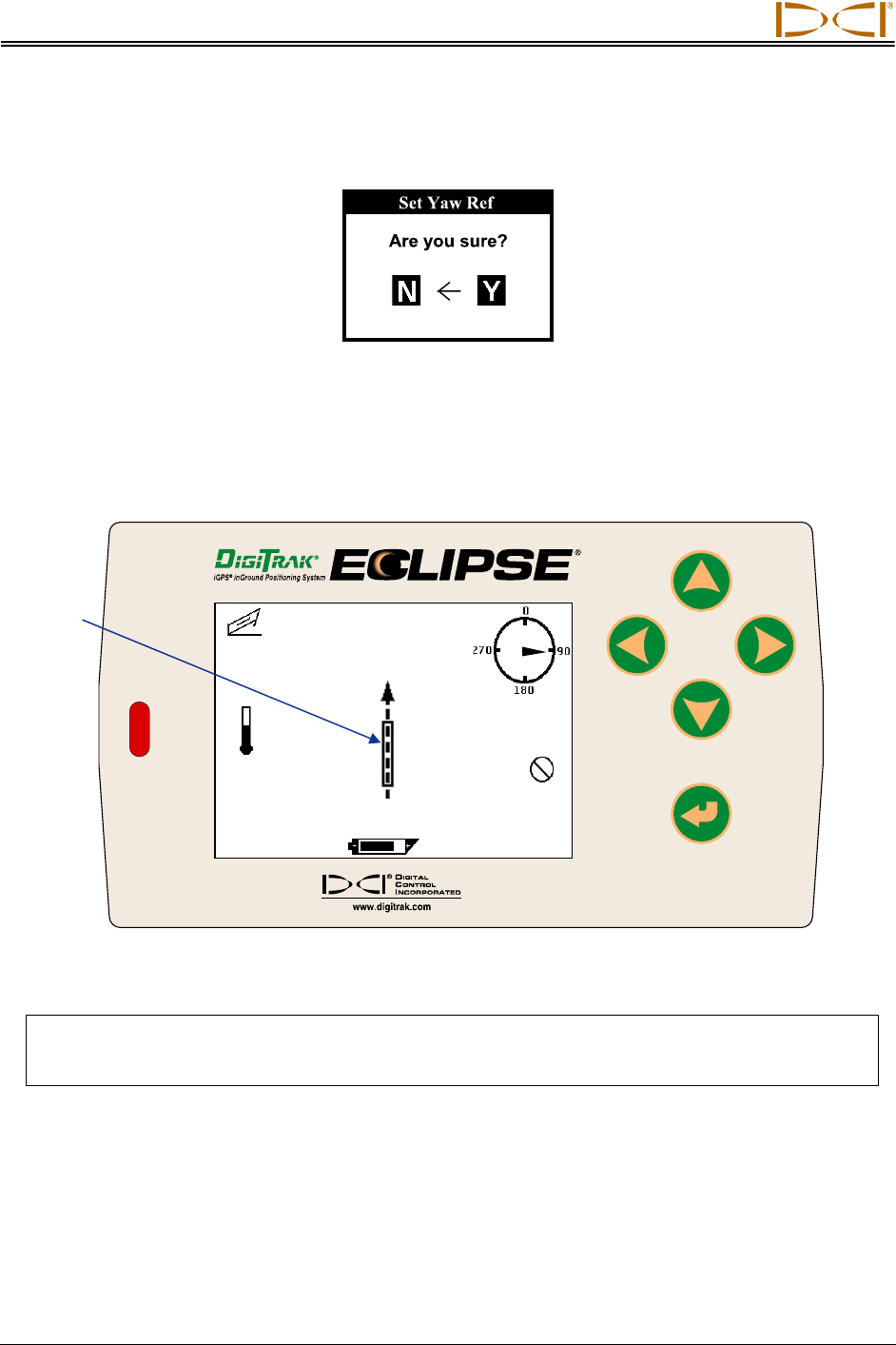
Write down this value as your Yaw Ref or reference heading. Push the remote display’s up arrow. You
will see the Set Yaw Ref dialog box.
Set Yaw Ref Dialog Box
Push the right arrow to Y for Yes, and push the execute button. You should now see that the Yaw Ref
number at the top of the screen matches the Yaw number at the bottom of the screen as shown here. The
Yaw Ref and Yaw are also graphically displayed by a dashed vertical line with an arrowhead and a long
rectangular box, respectively.
7.5
%
75
o
F
Yaw Ref:170.0
o
Yaw:170.0
o
90°
Tool
Icon
SST Remote Screen Showing New Reference Heading
NOTE: If possible, take a Ref Yaw reading at a different location along the borepath, and/or at
the exit location. This will allow you to determine an average Ref Yaw over the borepath
and possibly identify variations in the Yaw that could result in inaccurate readings.
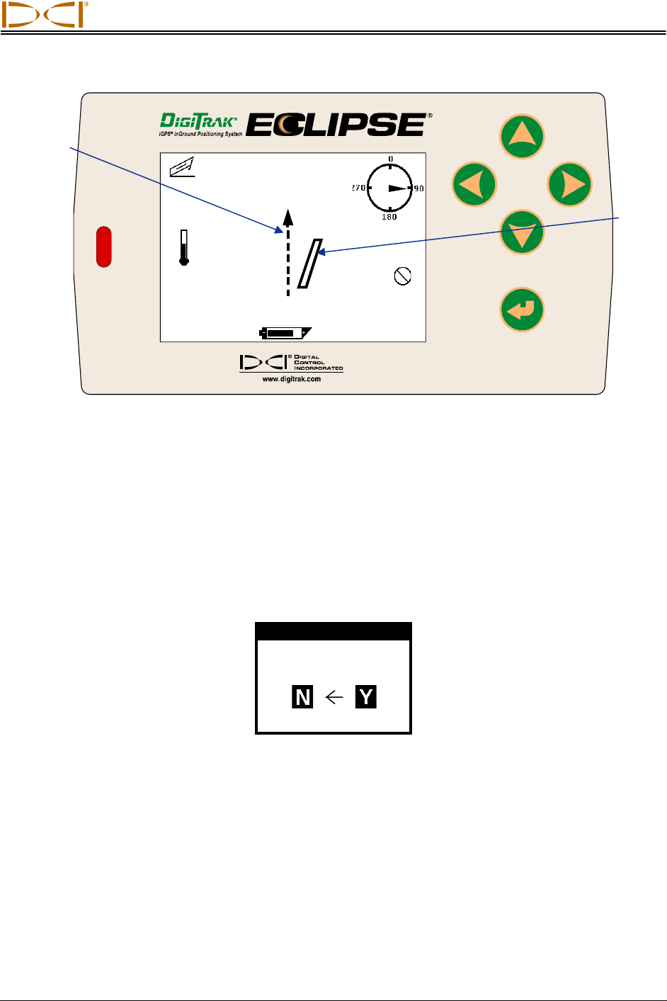
When the SST transmitter’s Yaw does not match the Ref Yaw the tool icon will be to the left or right of the
dashed line and a corresponding number will display above the tool icon to indicate the number of
degrees that the SST is off line, as in the example shown below. In this case, the heading of the SST is
60.7° off of the reference heading, which means the tool needs to be steered left 60.7°.
22 Eclipse® SST® Operator’s Manual
Operating Instructions
Eclipse® SST® Operator’s Manual 23
75
o
F
Yaw Ref:170.0
o
Yaw:230.7
o
60.7
o
90°
7.5
%
SST Remote Screen Showing Heading 60.7° to Right of Reference Heading
11. Set Roll Offset on Remote (if needed)
Using the remote display and the receiver, the SST transmitter’s 0° roll setting can electronically be
compensated if it does not match the bit’s 0° roll position. To compensate for a roll difference, the receiver
and remote display must have their Roll Offset functions set.
To set the Roll Offset on the remote display, push the right arrow (from the steering screen). The Set New
Roll Offset dialog box will display.
Set New Roll Offset
Are you sure?
Set New Roll Offset Dialog Box
Push the right arrow to Y for Yes and press the execute button. You will see the clock position on the
remote change to read 0°, and the Roll Offset value will appear at the top of the screen (240 in this
example).
Reference
Heading
Current
Transmitter
Heading
Operating Instructions
-0.2
%
68
o
F
Yaw Ref: 170.0°
Yaw:169.6°
0.4°
0°
Roll Offset: 240°
SST Remote Screen Showing New Roll Offset Value
End or Change Roll Offset on Remote – You have now set the Roll Offset on the remote display. At the
end of the drill run, or during the run if you want to change the Roll Offset value, you must remove the
Roll Offset value by ending the Roll Offset function. To end the Roll Offset, push the left arrow when at
the steering screen, then select Y for Yes and press the execute button.
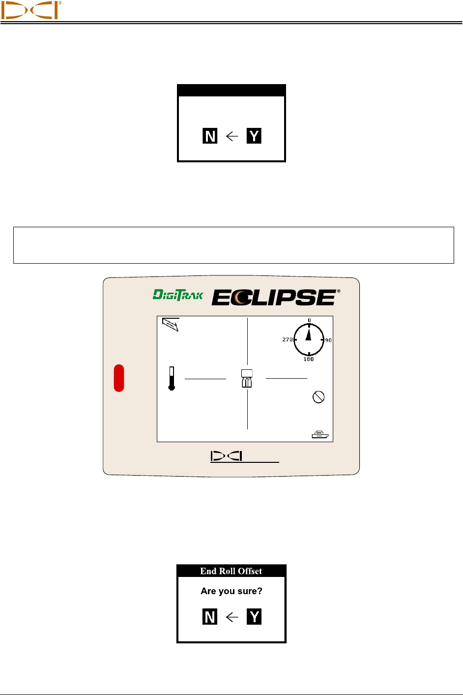
12. Set Roll Offset on Receiver
You are now ready to set the Roll Offset function on the receiver. With the receiver already in steering
mode, push the toggle to the right.
iGPS
®
inGround Positioning System
®
DIGITAL
CONTROL
INCORPORATED
®
www.digitrak.co m
CH:B1
768.5
-0.2%
90°
61°F
SST Receiver Display for Establishing Roll Offset Value
24 Eclipse® SST® Operator’s Manual
Operating Instructions
Push the toggle right to Y for Yes to set the new roll offset.
Set New Roll Offset
Are you sure?
Set New Roll Offset Dialog Box
You will see the clock position on the display change to read 0°, and the Roll Offset value will appear at
the top of the screen, as shown on the next receiver display.
NOTE: To record the most accurate data from the SST transmitter, the tool should be oriented to
the same roll position (or as close to it as possible) that it was at when the probe was
shot, which was 0°.
iGPS
®
inGround Positioning System
®
D
IGITAL
C
ONTROL
I
NCORPORATED
®
www.digitrak.com
CH:B1
768.5
-0.2%
0°
61°F
Roll Offset: 269°
SST Receiver Display Showing New Roll Offset Value
End or Change Roll Offset on Receiver – You have now set the Roll Offset on the SST receiver. At the
end of the drill run, or during the run if you want to change the Roll Offset value, you must remove the
Roll Offset value by ending the Roll Offset function. To end the Roll Offset, push the toggle left when at
the steering screen, select Y for Yes, and then click the trigger.
End Roll Offset Dialog Box
Eclipse® SST® Operator’s Manual 25
Operating Instructions
26 Eclipse® SST® Operator’s Manual
Calibrating SST Tool and Confirming Proper System Operation
13. Calibrate SST Tool to Receiver
In this step, you will use the receiver to conduct a high-frequency calibration, and then you will verify ac-
curate depth readings using a tape measure.
First, ensure that there are no metal structures within 30 ft (9 m), such as steel pipe, chain-link fence,
metal siding, construction equipment, or automobiles. Also make sure that the receiver is not positioned
over rebar or underground utilities. Check signal strength by selecting Steering from the main menu
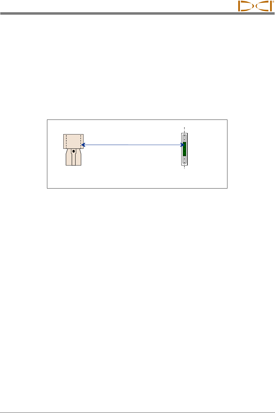
screen. Position the receiver 10 ft (3 m) to the side of the SST transmitter, as shown in the figure.
10 ft (3 m)
Eclipse SST
Receiver SST Transmitter
Centerline
SST
Transmitter
(Inside
Non-Mag
Housing)
10-Foot Measurement for Calibration Procedure
Verify that the signal strength at this distance is 580 to 590. Return to the main menu screen (toggle down
once). Select Configure on the main menu screen and click the trigger. Select 1 Pt. Cal. and follow the
prompts to complete a high-frequency calibration. Return to the steering screen, and check depth
readings at several locations against the tape measure.
14. Measure SST Transmitter Current Draw in Housing
Using an amp meter hooked up in series, as shown in the figure “Power Up SST Transmitter and Take
Amp Reading” in step 7, measure the current draw of the SST transmitter, a good reading is 0.2 to 0.5
amps.
15. Verify Pitch Readings Using Digital Level
Compare the SST transmitter’s pitch readings at the remote display and the receiver with those shown on
a digital level. Position the digital level on the housing, and then lift or lower the housing to different
inclinations and compare the readings on the level against the remote’s and the receiver’s pitch readings
to confirm accuracy.
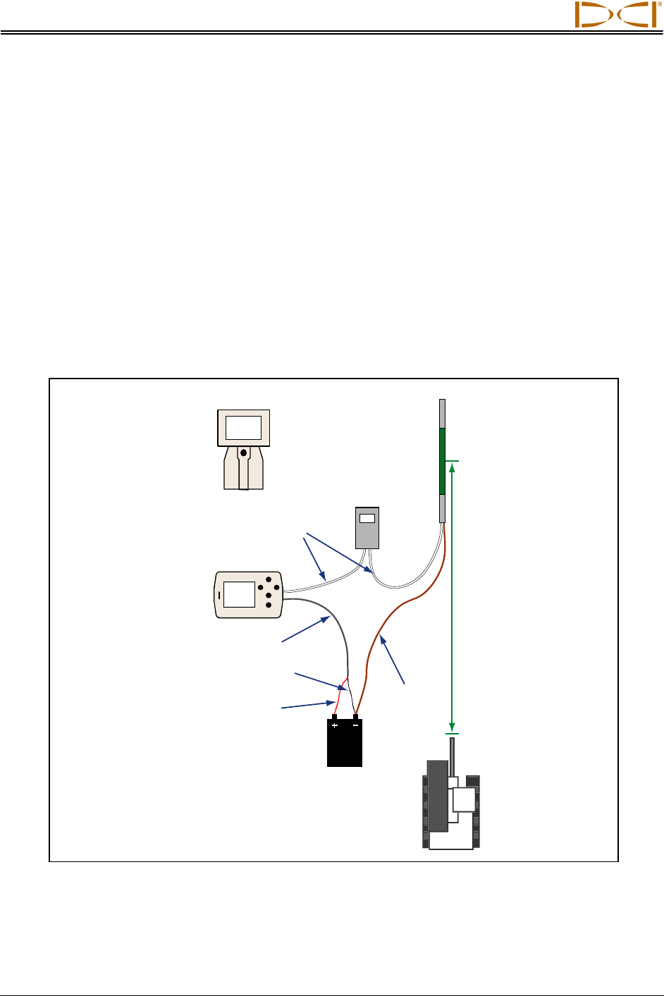
16. Connect SST Equipment to the Drill
You are now ready to connect the SST transmitter’s 10-gauge wire to the monel’s 10-gauge wire with a
butt splice and heat shrink. The monel is a non-mag drill pipe that measures approximately 15 ft (3 m) in
length and must be used between the non-mag housing and the regular drill pipe. Once this wire con-
nection is made, the housing can be threaded onto the monel while carefully pulling the slack in the wire
to ensure that the wire does not get caught in the threads.
Operating Instructions
Depending upon how the SST transmitter’s wire exits the drill pipe (through the drive chuck or the mud
swivel), connect this wire to the power supply’s white wire (see figure below). Connect the power supply’s
red wire to the positive battery terminal and the black wire to the negative terminal of the drill’s battery.
Power the remote display by pressing the execute button, select Steering from the main screen and
press the execute button.
Drill
Drill
Rods
Monel
Non-mag
Tooling
Assembly
SST Remote
Display with
Power Supply
White
Wire
Gray Cable
Black Wire
Red Wire
Ground Wire
12V
Battery
Laptop
Computer
Serial
Cable
Connecting SST System Components
Connect the remote display to the laptop with the serial cable. The laptop can be positioned as far as 50 ft
(15 m) from the drill. Power up the laptop, open the SST software, record job information using the Edit
menu to fill in the Drill Information fields. See Computer Instructions and Inputting and Changing Drill
Data sections later in this manual for complete instructions.
Open the Port menu option and select a port, then click on the START button under the COM Port Status
Window. Verify that the Status Ball to the right in the window is flashing and that you see live data. If you
cannot open a port, close it by clicking on the STOP button, then select a new port, and click on the
START button. You can also try closing the SST application and reopening it or, if you are still having
problems, rebooting the computer.
Eclipse® SST® Operator’s Manual 27
Operating Instructions
28 Eclipse® SST® Operator’s Manual
Logging Drill Run
17. Log First Point and Override Yaw Reading, If Needed
The first logged point should be recorded when the SST transmitter (in the housing) is positioned so that
it is ½ in and ½ out of the ground, as shown in the following diagram.
Surface of Ground
or Zero Reference
Elevation
Drill Head
Entering
Ground
Slots in
Housing
Tooling Position for First Logged Point
Once the tool is in position, press the computer’s LOG button. If the
remote display’s Yaw number does not match the laptop’s CURR
YAW value, you may want to override the yaw on the laptop before
logging. To override the yaw, click the check box to the left of the
Override box, and then manually type in the Ref Yaw number. Verify
that all readings are stable, and then click the LOG button.
LOG
Button
18. Locate, Continue to Log and Override, If Needed 0.3
354
271
178.9
178.0
0.9 (R)
50
68
LOG
As the tool moves away from the drill, the yaw readings should
match the Ref Yaw. Based on your steering commands and the
tool’s located position (using the receiver), you can determine if
overriding the yaw is necessary or not. Be sure to wait a few
seconds for all readings to stabilize before pressing the LOG button
or overriding.
CURR
YAW
Value
Override
Box
Operating Instructions
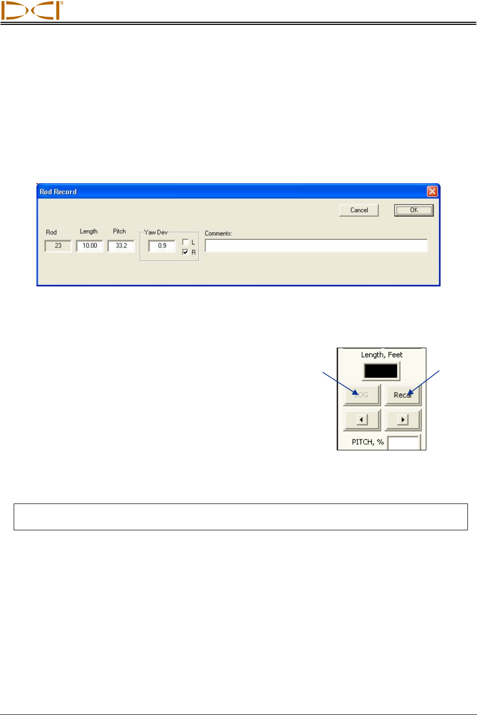
19. Compensate for Differences Between Tool’s Logged Position Data
and Tracked Position
Differences between the computer’s calculated position and the tool’s tracked position (DEV in the
laptop’s Logged Data field) can occur if the first reading was not taken when the SST was ½ in and ½ out
of the ground, such as when using a mud motor. In such cases, it may be necessary to compensate by
changing the pitch reading. To modify the pitch reading, place your mouse on the specific row of data in
the laptop’s Logged Data field and double-click to view the Rod Record dialog box (see figure below).
Note that, if you make a change to the data, the Rod number for that row will have an asterisk after it.
Rod Record Dialog Box
20. Pull Back Rods, Resteer, and Relog
Pullback Buttons in
Live Data Area
A
dvance
Retreat
If it is necessary to pull back and resteer the tool, you will use
the pullback buttons (Retreat and Advance) in the Live Data
area on the computer screen.
Every time you push the left-pointing Retreat button, you will
remove the data for the last logged data point from the Profile
and Deviation plots and also from the Logged Data field. If
you decide to not pullback after you have retreated rods, you
can press the advance button until you are back to the original
position or where you want to start resteering, and the original
data will reappear.
NOTE: Be careful to be methodical when pulling back and advancing rods so that you do not hit
the retreat button more times than the number of rods pulled back or advanced.
21. Save Bore Data Occasionally
DCI recommends that you save the bore data periodically during the bore. A suggestion is to include the
name of the project, the horizontal distance from the launch point (x-distance), and the SST software
version in the filename. For example, for a job where Pole Road is the name of the project, 880 ft is the x-
distance from the launch point, and the SST software version is 2.9, an appropriate filename would be
“Pole Road 880 v2.9”.
Eclipse® SST® Operator’s Manual 29
Operating Instructions
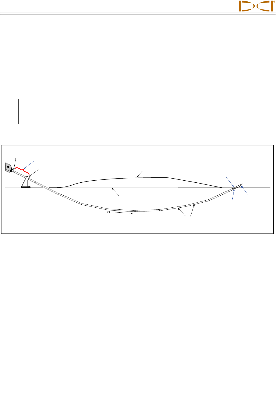
22. Log Last Rod
The last rod logged is just as important as the first. At the end of the run, with the tool at the exit location,
you must measure and document the length of the Last Rod so that you can enter it when you download
the drill data to the computer. The Last Rod measurement is the rod length minus the length of drill rod
left on the rack. For example, if you measure 6 ft (1.8 m) from the make-up/break-out clamps to the top of
the rod, then you would subtract 6 ft (1.8 m) from the rod length. If the rod length is 10 ft (3.0 m), then the
Last Rod measurement will be 4 ft (1.2 m).
NOTE: If the depth of the Last Rod is less than 24 in. (61 cm), you must set the ultrasonics
and log the last data point above the ground level for an accurate depth reading, or
you can record pitch only.
Top of Rod
Drill
Make-up/Break-out
Clamps
Drill Rods
Slots in
Housing
6 ft (1.8 m) Rod Length Left on Rack
Ground Surface
(Topography)
Zero Elevation
Reference Line Drill
Head
Termination / End
Point
Rod Length
(10 ft / 3.0 m)
Last Rod Measurement
23. Save Project
DCI recommends that you save the project at the end of the bore using at least two different names, so
that you have an extra copy of the data for backup. Then, if you accidentally make changes you don’t
want, you can still revert to the earlier version of the file. You may even want to save the bore data more
than two times.
When the SST software was loaded onto your computer, the default storage location was C:/Programs/
Digital Control Incorporated/Steering Tool 2.9. Within this folder will be a Drill Data folder, which is where
your bore will automatically be saved.
30 Eclipse® SST® Operator’s Manual

Operating Instructions
Summary of Basic Operating Procedure
¾ Setting Up SST Laptop
1. Establish borepath reference line and mark borepath.
¾ Setting Up Equipment and Site
2. Establish borepath reference line and mark borepath.
3. Assemble and torque up non-magnetic housing to non-mag tool.
4. Align drill to marked borepath.
5. Position and align non-mag tooling assembly onto marked borepath.
6. Stage SST equipment and power sources adjacent to tooling assembly.
7. Power up Eclipse SST equipment.
8. Measure SST transmitter current draw.
9. Install SST transmitter into aligned non-mag tooling assembly.
¾ Setting Reference Heading (Ref Yaw) and Roll Offset
10. Set Ref Yaw and shoot the probe.
11. Set roll offset on remote display (if needed).
12. Set roll offset on receiver.
¾ Calibrating SST Tool and Confirming Proper System Operation
13. Calibrate SST tool to receiver.
14. Measure SST transmitter current draw in housing.
15. Verify pitch readings using digital level.
16. Connect SST equipment to the drill.
¾ Logging Drill Run
17. Log first point and override yaw reading, if needed.
18. Locate, continue to log and override, if needed.
19. Compensate for differences between tool’s logged position data and tracked position.
20. Pull back rods, resteer, and relog.
21. Save bore data occasionally.
22. Log last rod.
23. Save project.
Eclipse® SST® Operator’s Manual 31

Operating Instructions
Notes
32 Eclipse® SST® Operator’s Manual
DIGITAL CONTROL INCORPORATED
Computer Software Instructions
Starting Steering Tool Program
There are three ways to start the Eclipse Steering Tool program:
¾ Double-click on the Steering Tool icon on the desktop.
¾ Use the Start button and select Start | Programs | Steering Tool | Steering Tool.
¾ From Windows Explorer, click on the SteeringTool.exe file in the C:\Program Files\Digital Control
Incorporated\Steering Tool folder, or the folder you have designated for the storage location.
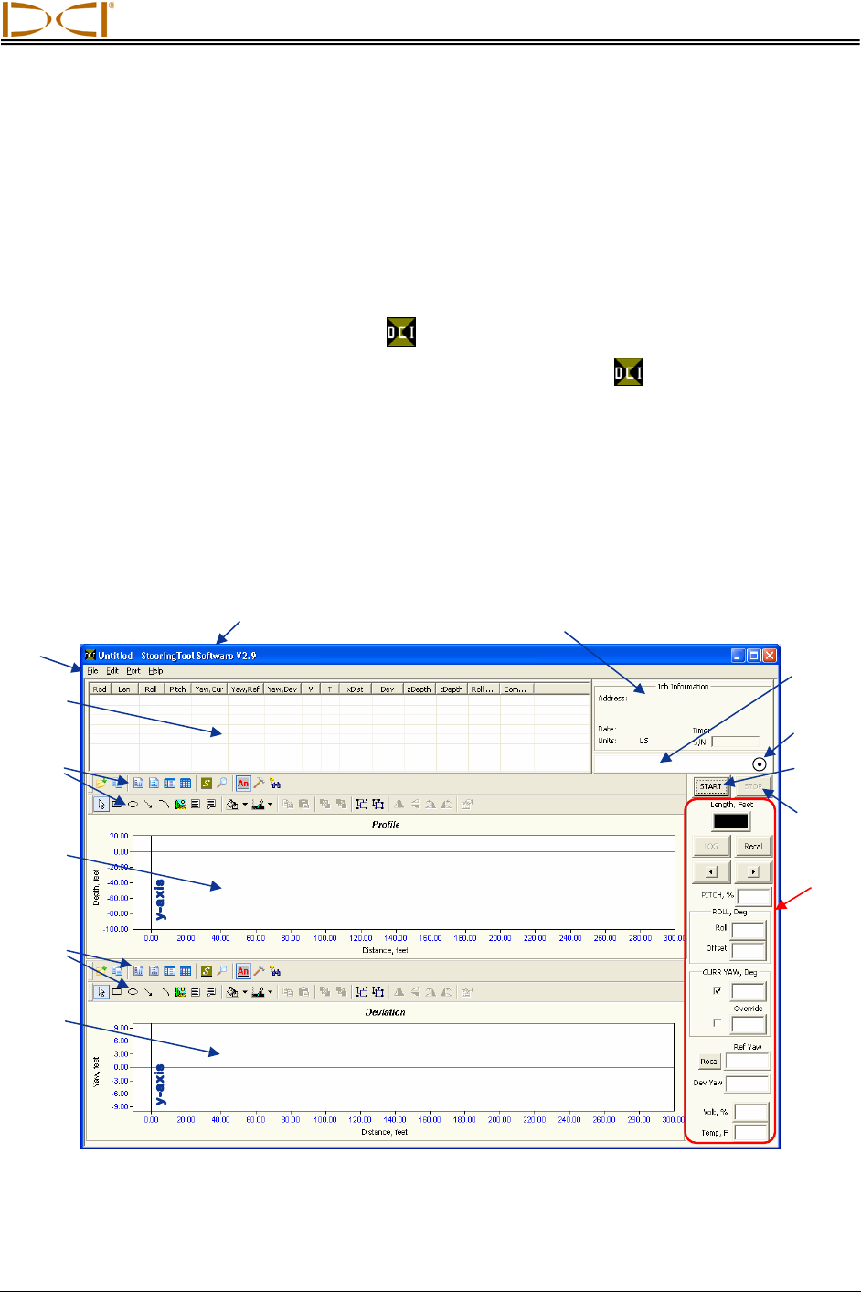
After you start up the program, you will see the main application window (see below). This window is also
generated from within the program by using the File | New command on the menu bar.
The Steering Tool software displays detailed information about the bore in a rod-by-rod tabular format. It
also shows a two-dimensional Profile plot of the bore and a bird’s-eye view of left/right deviation. The
main features and information areas are identified on the picture of the main application window shown
below, and then they are described in this subsection.
Title Ba
r
Job Information
Main Steering Tool Application Window
Menu
Bar
Logged
Data
COM Port
Status
Window
Deviation
Plot
Profile
Plot
x-axis
Status Ball
(flashes)
ST
A
RT
Button
Live
Data
STOP
Button
Profile
Plot
Toolbars
Deviation
Plot
Toolbars
x-axis
Eclipse® SST® Operator’s Manual 33
Computer Instructions
The SST Steering Tool software contains a sample data file (Demo V2.6.std) that you can use to famil-
iarize yourself with what the data looks like while drilling. You may want to open the sample data file and
use it for an example as we discuss the software in this section.
Menu Bar
Under each menu on the menu bar (File, Edit, Port, and Help) are commands for running the Steering
Tool program. Many of the commands are similar to those used in other Windows programs. This is
particularly true for the File and Help menu commands. The menu commands are summarized below.
File Menu Commands
¾ New – Creates a new blank project screen.
¾ Open – Opens an existing project.
NOTE: Before you open a new or existing project file by selecting
File | New or File | Open, you must save the project file that
is currently open. If you do not save the currently open file,
it will not automatically be saved but will revert to the last
saved version.
¾ Save – Saves an opened project using the same file name. If the pro-
ject has not yet been saved and named, then the file will automatical-
ly save to the default file name Untitled.std in the default file location of C:\Program Files\Digital
Control Incorporated\Steering Tool\Drill Data (see “Saving Project Files” later in this section).
¾ Save As – Saves an opened project to a specified file name and folder.
¾ Print – Prints a project.
¾ Print Preview – Displays the project on the screen as it would appear printed.
¾ Print Setup – Selects a printer and printer connection.
¾ Exit – Exits Eclipse Steering Tool program.
NOTE: DCI recommends saving your SST data regularly and with different names.
Edit Menu Commands
¾ Drill Information – Allows entry or editing of data in the Drill Informa-
tion field, which includes job, customer, and contractor data. The Drill
Information dialog box is also where measurement units are specified. If
units are not specified here, the SST system will use the default units of
English (feet) for distance, percent for pitch, and Fahrenheit for
temperature.
34 Eclipse® SST® Operator’s Manual
Computer Instructions
Specify
Measurement
Units Here
Drill Information Dialog Box
¾ Chart Autoscaling – Allows you to keep the entire Profile and Deviation points viewable during
the logging of a run. If Chart Autoscaling is not checked, then the Profile and Deviation plots will
go “off the chart,” or outside the viewable area. This feature may be useful if a run is very long.
Port Menu Commands
The Port menu has four options, which are listed as 1, 2, 3, and 4. These numbers
represent the serial (COM) ports available. The Port menu is used to select a COM
port for connecting the computer to the remote display to receive the SST trans-
mitter’s data.
For more information on how to connect the remote display to a port on your computer, see “COM
Port Status Window and START/STOP Buttons” later in this section.
Help Menu Commands
¾ Help Topics – Opens Eclipse Steering Tool Help file.
¾ About Steering Tool – Provides software version number and copy-
right information for Eclipse Steering Tool software.
Eclipse® SST® Operator’s Manual 35
Computer Instructions
Job Information
The Job Information field contains information about the
project/bore including the address, date, time, pitch units
(degrees or percent slope), and depth units (metric or feet).
The information is entered in this field by clicking on Edit |
Drill Information, and then clicking the checkboxes in the
right column of the Drill Information dialog box to indicate your choices for units. If you do not define the
depth or pitch units, the default setting of percent and feet will be used.
Logged Data
The Logged Data field contains 15 columns of rod-by-rod drill data about the bore. The type of data pro-
vided under each column heading is described below.
¾ Rod – A sequential listing of data for each logged point or rod. Because the distance between
logged points can vary to accommodate different drilling conditions, the number of logged points
will not necessarily match the number of actual rods drilled. For example, when considerable
pitch changes occur, it is best to log data several times along one or more rods. An asterisk (“*”)
will appear next to the rod number if the data for that rod has been changed in the computer.
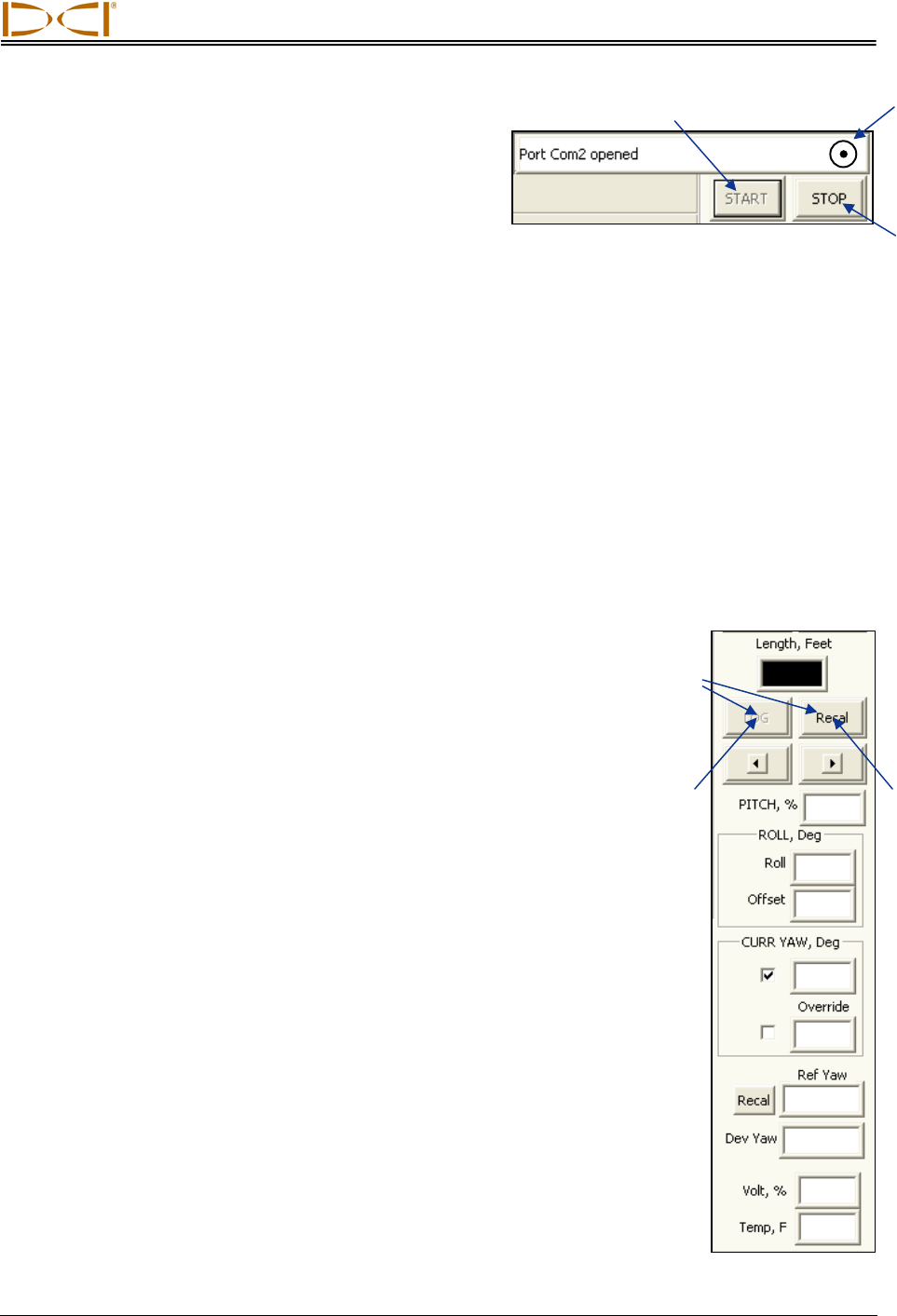
¾ Len – Typically the length of one drill rod or the distance between data recordings. Len can be
changed as needed to compensate for logging more than one data point on a long (30-ft [9-m])
rod or when there are considerable pitch changes, such as at the beginning or the end of a bore.
This enables a more accurate calculation of the transmitter’s depth. This value is the same as
that appearing in the Length box in the Live Data field (see “Live Data” later in this section).
¾ Roll – The roll position displayed in degrees from 0 to 360, where 12 o’clock is equal to 0°,
3 o’clock is equal to 90°, 6 o’clock is equal to 180°, and 9 o’clock is equal to 270°.
¾ Pitch – The inclination of the transmitter displayed in percent or degree increments. This setting
can be changed using the Edit | Drill Information menu option.
¾ Yaw, Cur – The current yaw or heading of the SST transmitter displayed in degrees when the
data was logged.
¾ Yaw, Ref – The reference heading of the intended borepath (when you shot the probe). The
reference heading can be changed if necessary at the remote display or on the laptop.
¾ Yaw, Dev – The difference between the current yaw and the reference yaw displayed in degrees.
Positive deviation is to the right and negative deviation is to the left of the reference yaw.
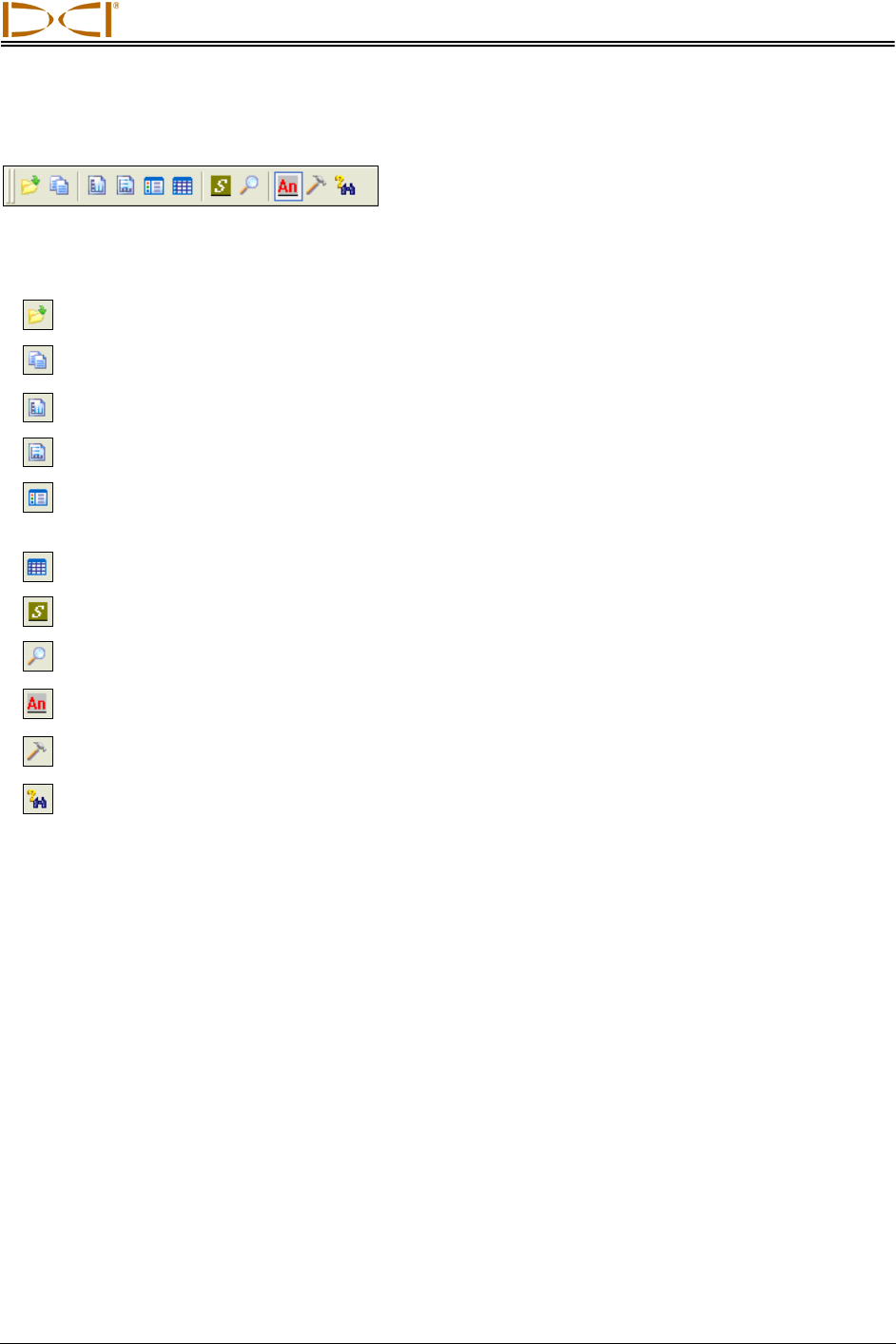
¾ V – The status of the above-ground battery powering the SST transmitter in percent of power
remaining. A low battery has 12V or less remaining; a full battery has 24V.
36 Eclipse® SST® Operator’s Manual
Computer Instructions
T – The temperature of the SST transmitter in degrees Fahrenheit, when using English units
(feet), or in degrees Celsius, when using metric units.
xDist – The transmitter’s horizontal distance from the launch point. Note that this is not the length
of the actual borehole. This value is measured along the x-axis.
Dev – The transmitter’s lateral (left/right) distance from the borepath’s reference heading, dis-
played in either feet or meters. A positive value is to the right and below the x-axis in the Devi-
ation plot.
zDepth – The depth of the transmitter displayed in either feet or meters. This value may be above
or below the x-axis or drill rig elevation (which is the zero elevation line).
tDepth – The total depth of the transmitter measured from the topography that has been
manually entered using the Data Editor (see Inputting and Changing Drill Data section) or im-
ported from an Excel file (see Appendix: Importing Topography Drill Plan and Tool Deviation). If
no topography data has been entered manually, the tDepth will be the depth below the zero
elevation line, and it will be the same as the zDepth.
Roll Offset – The value (in degrees from 0 to 360) used to compensate for the difference
between the tool bit’s roll orientation and the SST transmitter’s roll orientation.
Comments – Information can be added in the Comments column by double-clicking on the row
where you want to add a comment to display the Rod Record dialog box, where you can enter a
comment .
Profile Plot Ground Surface
Start of
Bore
OnBa
r
lines
Borepath
Cursor Coordinates
The Profile plot area shows the bore’s progress in a two-dimensional Profile view. As the bore pro-
gresses, and more data points are logged, an automatic scaling feature formats the plot area so that the
entire bore remains viewable and does not go “off the chart” (see Chart Autoscaling under “Edit Menu
Commands” earlier in this section). If you place the mouse pointer or cursor anywhere in the plot area
and then hold down the left mouse button, you will see dashed vertical and horizontal lines that intersect
at the cursor location and a pop-up box that displays the cursor coordinates. This location and the dashed
lines are referred to as the OnBar.
In the Profile plot shown above, the cursor location is at the intersection of the two dashed OnBar lines.
The numbers in the pop-up box (105.41, -28.97) correspond to the cursor coordinates.
The cursor can also be positioned on the logged points for additional data.
Eclipse® SST® Operator’s Manual 37
Computer Instructions
Deviation Plot
Start of
Bore
OnBa
r
lines
Cursor Coordinates Borepath
The Deviation plot area shows the lateral (left/right) deviation of the transmitter from the reference line.
The plot is at the same horizontal position as the Profile plot, but from a bird’s-eye view. As with the
Profile plot, this window has an automatic scaling feature to keep the plot “on the chart.” The OnBar lines
and cursor coordinates will appear whenever you place the cursor anywhere in the chart area and hold
down the left mouse button.
Plot Area Toolbars
Standard
Toolbar Annotate
Toolbar
When you open the SST software, you should see two rows of icons above both the Profile and Deviation
plot areas. The upper row is the standard toolbar, and the lower row is the annotate toolbar. The standard
toolbar allows you to do a variety of functions with the drilling data, and the annotate toolbar primarily
provides drawing and formatting tools to customize the appearance of the information in the plot area.
Access Toolbars – If you do not see the toolbars, place the cursor in either the Profile or Deviation plot
area and right click to view a popup menu (as shown in the graphic below). Click on the Toolbars option,
then click either Toolbar or Annotate Toolbar to display that toolbar above the plot area.
Popup
Menu
38 Eclipse® SST® Operator’s Manual
Computer Instructions
Standard Toolbar
The icons available on the standard toolbar are briefly described below. For details on how to use them,
see “Graphing Options” in the Inputting and Changing Drill Data section.
Import Topography Enables the import of topographic data from an Excel file.
Copy to Clipboard Copies data as a bitmap, metafile, or text file to the clipboard to save in
another format.
Vertical Grid Displays vertical grid lines on the graph.
Horizontal Grid Displays horizontal grid lines on the graph.
Series Legend Displays the four graphed plots (Tool Depth, Topography, Interpolated
Topography, and Drill Plan) with their symbols in a legend box, which is by
default at the bottom of the Profile plot area.
Data Editor Allows manual entry of topographic and planned bore data.
AutoScale Charts Keeps entire drill path and topo on the screen.
Zoom Allows you to zoom in on areas of the graphs by clicking and dragging the
mouse to define a zoom area.
Annotate ToolBar Displays the annotate toolbar below the standard toolbar, or closes it if it is
already displayed.
Tools Provides another means to access some toolbar functions as well as the
PaletteBar and the PatternBar.
Search This function does not work in the SST software.
Eclipse® SST® Operator’s Manual 39
Computer Instructions
Annotate Toolbar
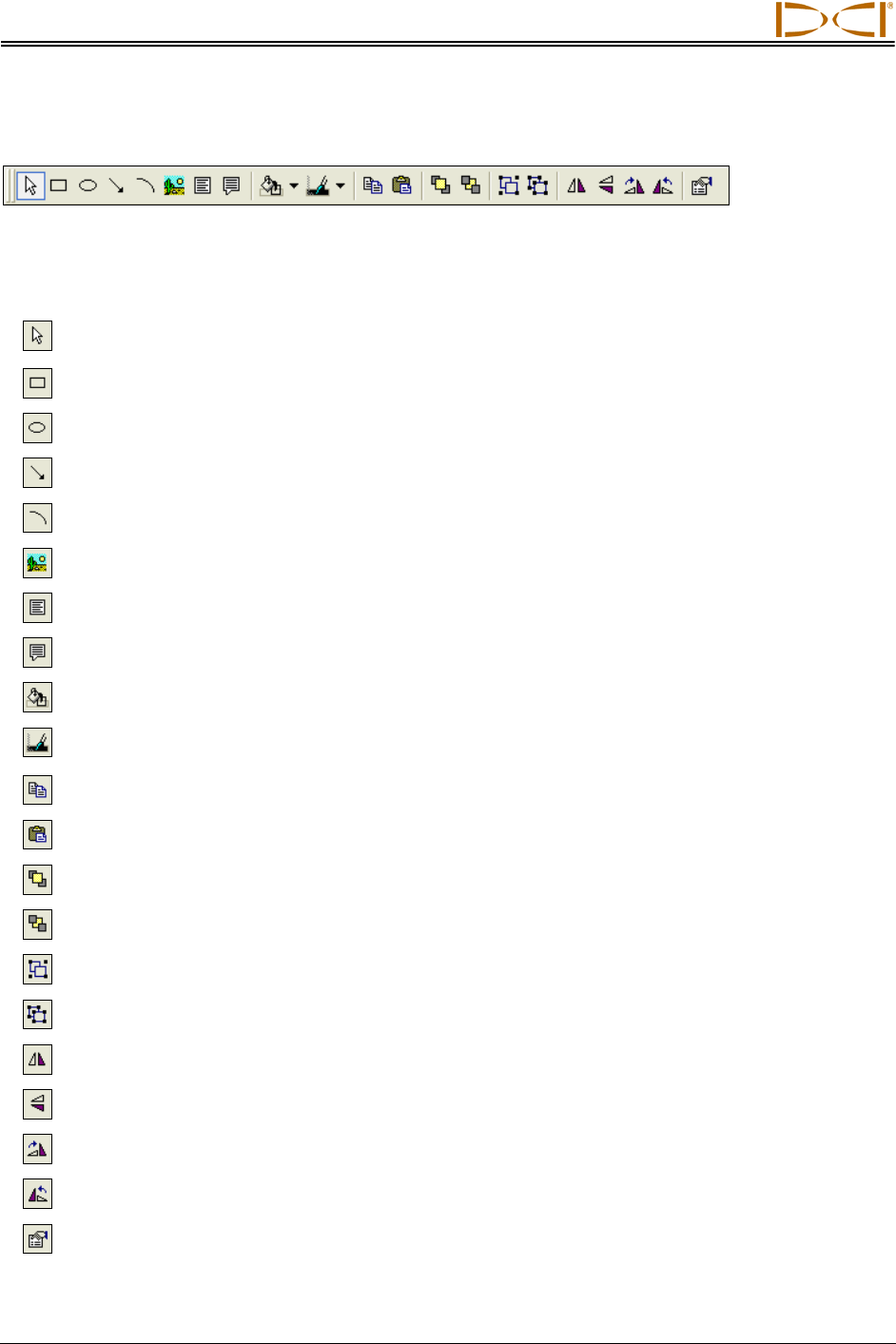
The icons available on the annotate toolbar are briefly described below. These icons enable functions
similar to those provided in standard drawing applications. For details on how to use them, see “Graphing
Options” in the Inputting and Changing Drill Data section.
Pointer Allows cursor to be used as a selection tool and shows OnBar and
coordinates for cursor point when left mouse button is clicked.
Rectangle Used to draw a square or rectangle in the plot area.
Circle Used to draw an oval or circle in the plot area.
Arrow/Line Used to draw an arrow or line in the plot area.
Arc Used to draw a curved line in the plot area.
Picture Pastes artwork for another application.
Text Box Inserts text box in plot area and enables text to be typed in it.
Balloon with Text Inserts balloon-type text box in plot area and enables text to be typed in it.
Background Color Used to change the color of the background in the plot area.
Foreground
(Border) Color Used to change the color of the foreground or border in the plot area.
Copy Copies selected item to clipboard.
Paste Pastes item that has been copied to the clipboard.
Bring to Front Brings selected item to the front of other objects.
Send to Back Sends selected item to the back of other objects.
Group Groups selected objects.
Ungroup Ungroups selected group.
Flip Vertical Flips object along its vertical axis.
Flip Horizontal Flips object along its horizontal axis.
Rotate Right Rotates selected object in clockwise direction in 90° increments.
Rotate Left Rotates selected object in counterclockwise direction in 90° increments.
Properties Opens properties dialog box for the selected object.
40 Eclipse® SST® Operator’s Manual
Computer Instructions
COM Port Status Window
and START/STOP Buttons
The COM Port Status Window indicates whether a COM
(serial) port is open and connecting the computer to the
SST transmitter through the remote display. The Status Ball on the right flashes when the computer is
receiving data from the SST transmitter. The START and STOP buttons are used for opening and closing
a port.
Open
Port
Status
Ball
Close
Port
A COM port must be open before bore data can be logged. To open a COM port, select Port from the
menu bar, and then select one of the four options (1, 2, 3, or 4). COM port 1 is typically selected. Click on
the START button, and, if the SST transmitter is connected and functioning, you will see the status ball
begin to flash and a message showing that a COM port is open. To disconnect from a port, click on the
STOP button.
To determine the computer’s available ports, open your computer’s Control Panel and click on the
System icon to open the System Properties dialog box. Click on the Hardware tab and then the Device
Manager option at the top to open the Device Manager dialog box. Click on “Ports” in the listing to view
the available ports on your system. You can select each port individually to see if it will open and function.
The open port will only function when live data is being received from the SST transmitter.
If you cannot open a port after you have identified one using your computer’s system properties hardware
settings in the Control Panel, close the Eclipse Steering Tool program
and reopen it. Select the desired port, and click on the START button. If
this does not solve the problem, then call DCI Customer Service, for
assistance.
Retreat
Pullback
Buttons
Live Data
This area of the application window displays live data from the SST
transmitter when it is powered up and the computer is connected to the
remote display. The types of information displayed are described below,
starting at the top of the data area.
A
dvance
¾ Length, Feet – An input box for the distance between logged
points (with units shown based on options selected in the Job In-
formation field). This distance must be typed in before you can
log data. The length is typically the length of one drill rod. It may
be advisable to record data at shorter intervals, particularly if con-
siderable pitch changes occur. This field will default to the most
recent length entered, so be sure to correct the value in this box if
you have changed the distance between log points. You can
change the length setting at any time by simply clicking the cursor
in this box and then typing in the desired length.
¾ LOG Button – Used to log data. This button can only be activa-
ted when a COM port is open and the computer is receiving data
from the SST transmitter. To log data, press the LOG button—the
new data will appear in the Logged Data field, and the Profile and
Deviation plots will automatically update. Always verify accuracy
of Live Data prior to logging. Be sure to orient the tool to 0° and
wait 10 seconds to ensure stable, accurate data.
Eclipse® SST® Operator’s Manual 41

Computer Instructions
¾ Recal Button – Used to redraw or refresh the graph if data has changed.
¾ Pullback Buttons – Used to pull rods backward (retreat) or forward (advance) in the computer
program. The left arrow button is used when the tool is pulled back for redirection. When you
press the left arrow button, the data for the pulled back rod will disappear and the Profile and
Deviation plots will get shorter. When you press the right arrow button, the data will reappear and
the Profile and Deviation plots will get longer.
When tool redirection (pullback) is required, press the left arrow until the appropriate number of
rods has been “pulled back”. Be sure to communicate with the drill operator to ensure that the
same number of rods is pulled back. As the bore is redrilled, you will press the LOG button to log
the redrilled rods. When you do this, you will no longer see or have access to the old rod data (or
portions of the Profile and Deviation plots) because you have now “logged over” the old data.
NOTE: It is recommended that, before pulling back rods, you save data as a different file name,
such as Bore1Rev1, Bore1Rev2, etc. (see “Saving Project Files” later in this section). It is also
recommended that, prior to drilling and pulling back, you make a rod count.
¾ PITCH, % – Displays the current pitch of the transmitter, in either percent or degrees (depending
upon the units selected in the Job Information field).
¾ ROLL, Deg – Displays the current roll and roll offset positions for the transmitter, in degrees.
¾ CURR YAW, Deg – Displays yaw (heading) information for the transmitter. This field contains two
checkboxes and two data input boxes. A check mark will appear in the top box, with the current
heading of the transmitter in the adjacent data input box. If it is determined that this information is
not correct, due to a localized interference source, it is possible to override the current yaw
setting to one that is believed to be correct. To override the current yaw, click on the second
checkbox (to enter a checkmark), and then enter the appropriate yaw value in the adjacent data
input box labeled Override.
NOTE: Yaw readings may vary with roll orientation. Always use the same roll position to log data
or click the checkbox next to the Override input box.
¾ Ref Yaw – Displays the reference heading established when you shot the probe. This is provided
as a quick comparison to the CURR YAW described above. The value is identical to the value for
Yaw, Ref in the logged data.
The Ref Yaw gets recorded on the laptop when the first data point is logged. The information is
sent from the remote display, where it is called the Yaw Ref. The Ref Yaw can be changed at any
time on the laptop as required; it can also be changed on the remote display.
¾ Ref Yaw Recal Button – This will redraw the graph if the Ref Yaw is changed.
¾ Dev Yaw – Displays the left/right deviation of the SST transmitter measured in degrees. This
value is the difference between the Ref Yaw and CURR YAW. The value is identical to the value
for Yaw, Dev in the logged data. Positive values to the right, negative values to the left.
¾ Volt, % – References the input voltage, 12V to 24V DC.
¾ Temp, F – Displays the temperature of the SST transmitter in degrees Fahrenheit, if English units
are being used, or in degrees Celsius, if metric units are being used. Normal drilling temperature
ranges are 60–82°F (16–28°C)
42 Eclipse® SST® Operator’s Manual
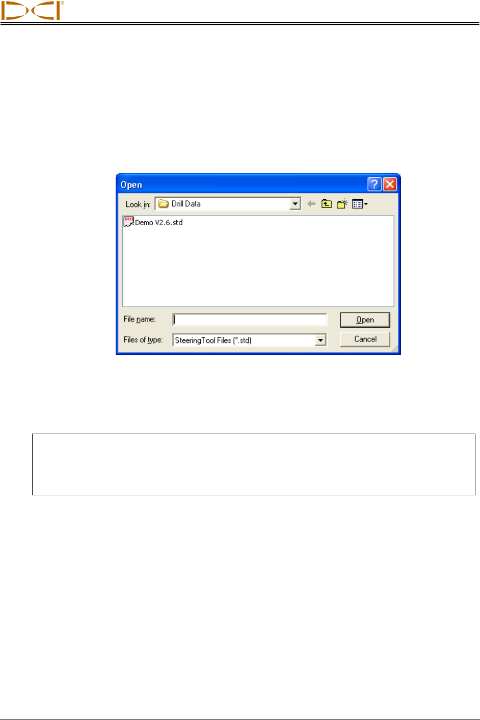
Computer Instructions
Opening Project Files
1. To open an existing drill project from within the Steering Tool program, select Open from the File
menu. You will see the Open dialog box and a list of available project files (with the file extension
“std”) in the folder that was last used. If this is the first time the program is being used, the Open
dialog box will show the Drill Data folder under the Steering Tool program file with only one file,
Demo V2.6.std. The default location for storing project files is C:\Program Files\Digital Control
Incorporated\Steering Tool\Drill Data.
Open Dialog Box
2. Select the desired project file (in this example, Demo V2.6.std), or navigate to the folder where
you have stored your project files and select the desired file. Then click on Open. You will see the
data appear in the application window.
NOTE: Recorded bore data can only be opened with the exact same version of software as
when it was recorded. If the SST computer software is upgraded, do not overwrite or
erase older versions of the software, since you will need them to open old bore files. It
may be a good idea to save the bore file using the version number in the file name
(e.g., Bore1v26.std, Bore1Rev1v26.std, etc.)
Printing and Previewing Project Files
1. If you want to preview the printed pages before you send the file to print, select Print Preview
from the File menu. The example shown below is in portrait orientation. For a long bore, you can
change your print setup to landscape orientation (under File | Print Setup …) so that the bore
details are not as compressed.
Eclipse® SST® Operator’s Manual 43
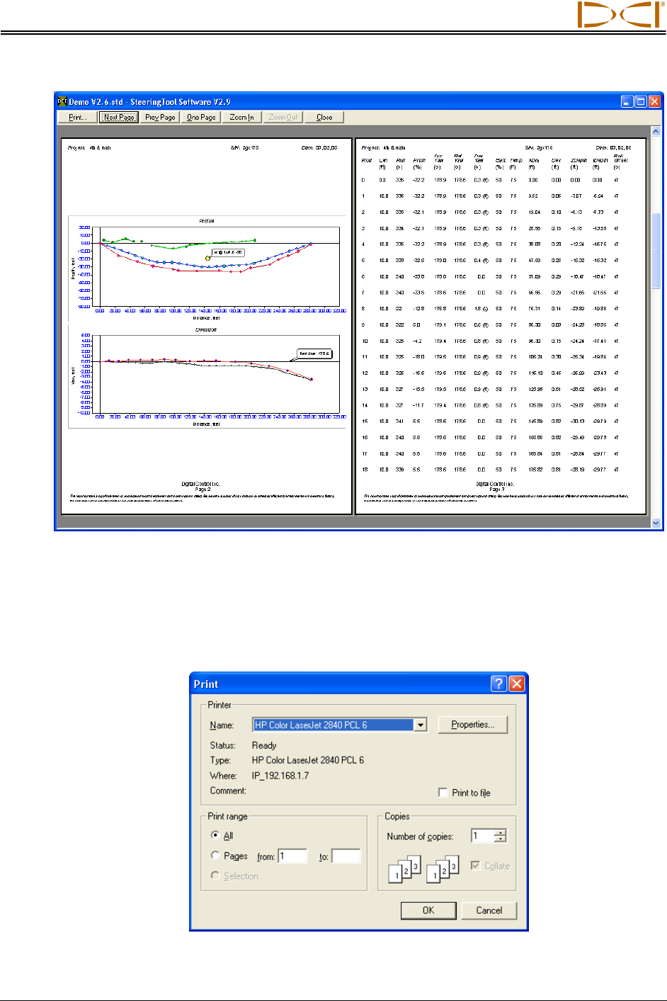
Computer Instructions
Print Preview of Drill Data (Pages 2 and 3)
2. The entire bore’s data will print on at least three pages. The drill information (which includes the
job site and customer and contractor data) will appear on the first page, the Profile and Deviation
plots will be on the second page, and the drill data listed in the Logged Data field will print on the
third page (and more if needed).
3. To print the project data, select Print from the File menu. You will see the Print dialog box.
Print Dialog Box
44 Eclipse® SST® Operator’s Manual
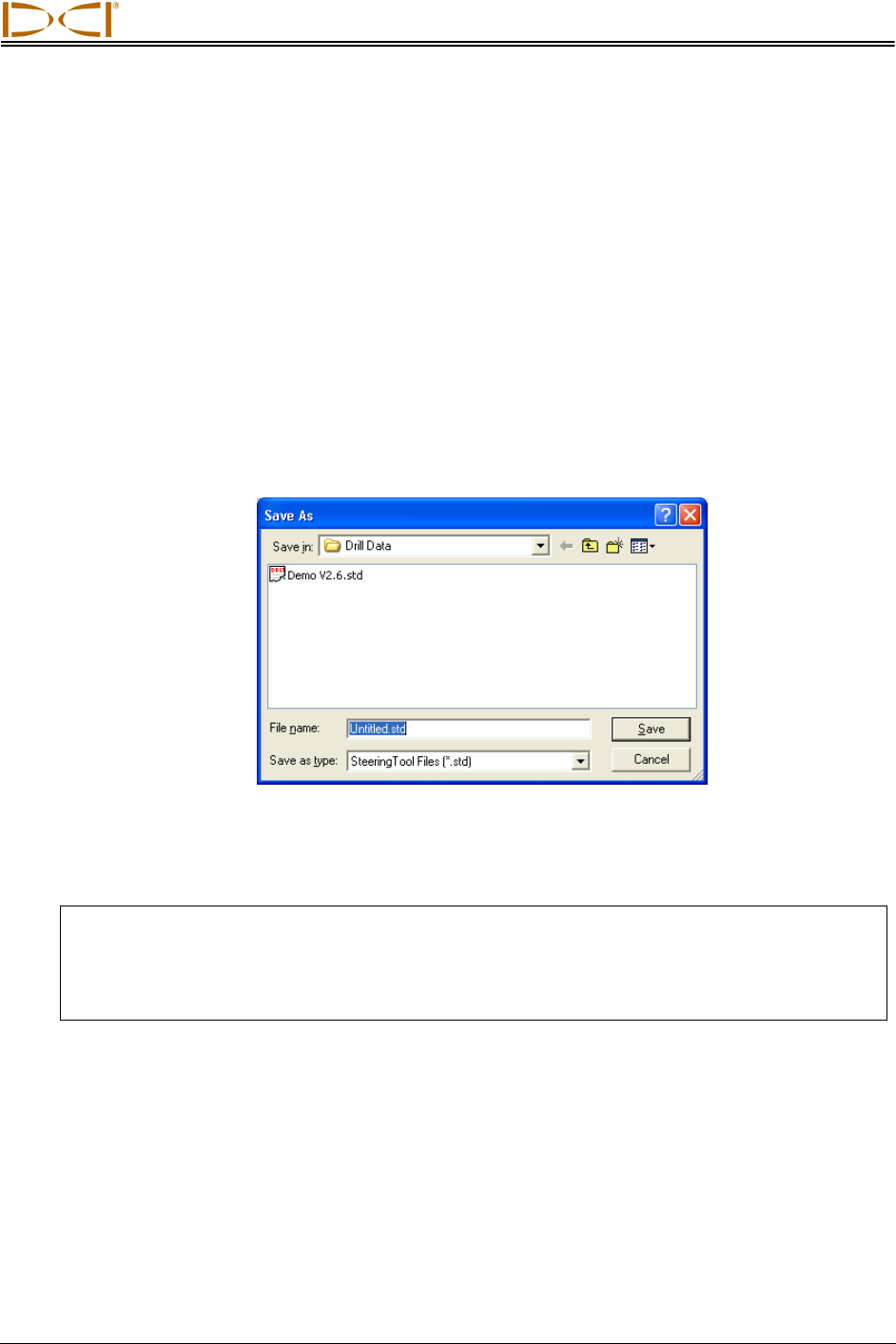
Computer Instructions
4. Make any adjustments needed in the Print dialog box, then click OK. If you have the Adobe
Acrobat PDF writer software, you can select the Adobe PDF printer to print to a PDF file (see
your software documentation). This allows you to save the file as a PDF, which can be e-mailed
to and viewed by anyone with Adobe Acrobat reader (available at no charge on the Internet).
Saving Project Files
1. To save an open project file, select Save from the File menu. The file will automatically be saved
under its current file name (shown on the left in the title bar) and location. If the project has not
yet been saved and named, then the file will automatically save to the default file name
Untitled.std in the default location for storing project files (C:\Program Files\Digital Control
Incorporated\Steering Tool\Drill Data).
2. To save a file with a different file name or location, select Save As from the File menu. You will
see the Save As dialog box, which automatically opens to the folder where the current file is
stored.
Save As Dialog Box
3. Change the file name and location as desired, then click Save. The open file will now have the
new file name and/or location.
NOTE: Recorded bore data can only be opened with the exact same version of software as
when it was recorded. If the SST software is upgraded, do not overwrite or erase older
versions of the software, since you will need them to open old bore files. It may be a
good idea to save the bore file using the version number in the file name (e.g.,
Bore1v26.std, Bore1Rev1v26.std, etc.)
When you save a project file, the file name will end with “std” (e.g., Projectname.std). The Eclipse
SST program also generates four accompanying files: two “chd” files (Projectname PlanView.chd
and Projectname Profile.chd) and two “txt” files (Projectname PlanView.txt and Projectname
Profile.txt).
Eclipse® SST® Operator’s Manual 45
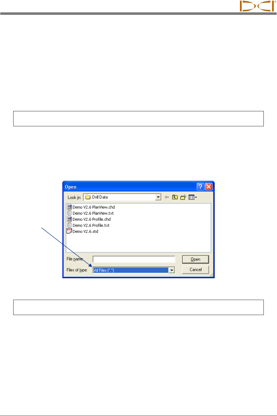
Computer Instructions
E-mailing Project Files
You can send Eclipse SST project files via e-mail. E-mailed files can be opened on any computer that has
the same version of the Eclipse SST software as used on the originating computer.
The Eclipse SST program generates five files for each run: the standard SST file (*.std) and four other
files related to the plots. For example, for the project file named “Projectname.std”, there will be two *.chd
files (“Projectname PlanView.chd” and “Projectname Profile.chd”) and two *.txt (“Projectname
PlanView.txt” and “Projectname Profile.txt”).
NOTE: All five project files (the *.std, *.chd, and *.txt files) must be e-mailed and saved to
the same folder on the receiving computer so that the data will display correctly.
To e-mail files for a project, select the five project files as attachments in your e-mailing application, and
then send the e-mail. The default location of the Eclipse SST program data is C:\Program Files\Digital
Control Incorporated\Steering Tool\Drill Data. You can see the different file types under the Drill Data
folder by setting the drop-down selection at the bottom of the open dialog box to “All Files (*.*)”, as shown
below. Note that the five files that comprise the data for the SST project named “Demo V2.6” are listed in
this dialog box.
Select
“All Files
(*.*)”
Open Dialog Box Showing All Files (*.*)
NOTE: If you have made a PDF file of the project data, then you can select the PDF file for
e-mailing.
46 Eclipse® SST® Operator’s Manual
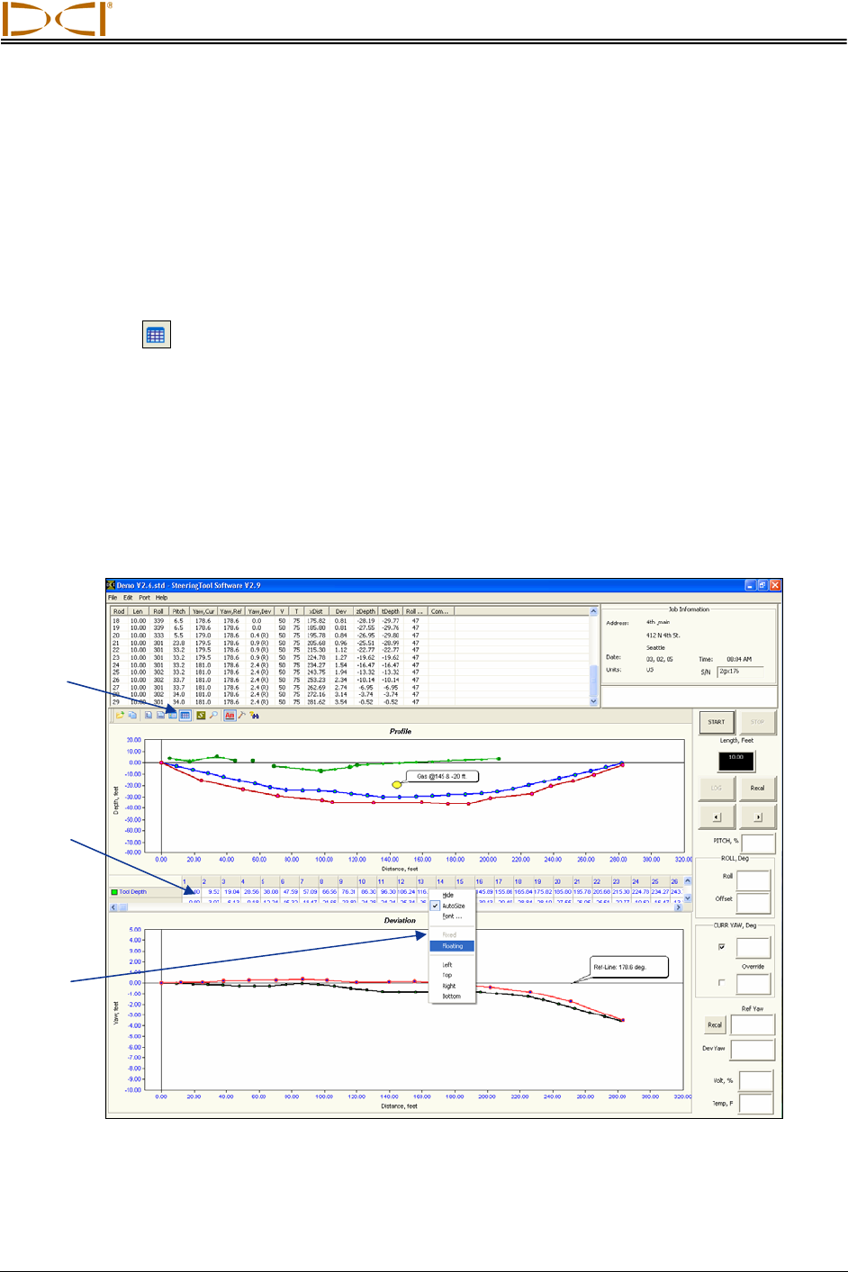
DIGITAL CONTROL INCORPORATED
Inputting and Changing Drill Data
You can manually edit SST project files by plotting topography (topo), planned bore (drill plan), and
planned deviation (tool deviation) into the SST software either before, during, or after a bore. You can
also import this information from an Excel file, but it must be done prior to logging a SST bore. The
instructions for importing information from an Excel file are provided in the Appendix.
The Data Editor is used to enter topo, drill plan, or planned deviation data manually in either the
Profile or Deviation plot. To open the Data Editor, click on the icon in the toolbar or, if the toolbar is not
displayed, right click in the plot area and then select the Data Editor from the popup menu.
Clicking on the Data Editor icon will open the Data Editor table at the bottom of the plot area. The table
will be partially hidden and will have scroll bars to allow viewing of the hidden data. To move the Data
Editor table for easier viewing and editing, place the cursor in the table area and right click, then select
the Floating option from the popup menu. The data table will then be in a box that you can move around
the plot area; place your cursor on the top blue title bar, then click and hold the left mouse button while
dragging the box to a new location. The following graphics show the data table as it appears when you
first open it and as it appears after you have selected the Floating option.
Data Editor
Icon
Fixed
Data
Table
Popup
Menu
Locating Toolbars and Data Tables
Eclipse® SST® Operator’s Manual 47
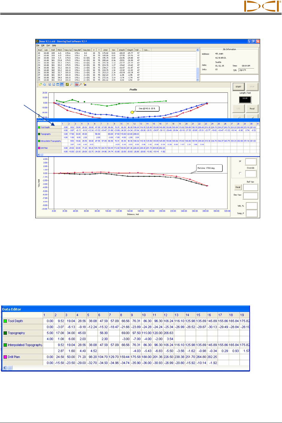
Changing Drill Data
48 Eclipse® SST® Operator’s Manual
Floating Data Table
To close the table, whether it is floating or fixed, place the cursor in the table area and right click, then
select the Hide option from the popup menu. You can also close the table by clicking on the Data Editor
icon.
Entering Topography and/or Drill Plan
Data Editor Table for Profile Plot
The Data Editor table for the Profile plot has numbered columns across the top of the table that cor-
respond to the locations where data will be or has been logged. Column 1 contains data for the first
logged point; column 2 contains data for the second logged point, etc.
Floating
Data
Table
Computer
Generated
}
}
}
}
Manually
Entered
Computer
Generated
Manually
Entered

Changing Drill Data
The Profile plot table lists the four plotted profiles—Tool Depth, Topography, Interpolated Topography,
and Drill Plan. The upper row for each of these plots gives the x-coordinate or horizontal distance from
the launch point. The lower row gives the y-coordinate, or the distance above or below the zero elevation
line or x-axis.
Tool Depth – These x,y coordinates are computer generated automatically by the SST system’s
software when you log the bore—you will not enter any information in these two rows.
Topography – These x,y coordinates are based off of the zero elevation
(launch point) and are manually entered either prior to, during, or after the bore. If the topography
is below the zero elevation line, you must enter a minus (“–”) sign; however, if the topo is above
the zero elevation line you do not have to enter a plus (“+”) sign.
Interpolated Topography – These x,y coordinates are computer generated automatically by the
SST system’s software when you log the bore—you will not enter any information in these two
rows.
Drill Plan – These x,y coordinates are used for plotting a planned bore and are manually entered
either prior to, during, or after the bore. If the drill plan is entered after the topography has been
entered, the y-value will be based off of the topo . If no
topo is entered, the y-value will be based off of the zero elevation line.
If you are using English units of measure for depth, the number must be in decimal format for feet; e.g., if
you want to use the value 4 ft 8 in., you will enter 4.67. If you are using metric units of measure for depth,
then the number must be in decimal format for meters. The values for the x,y coordinates for the
Topography and Drill Plan will be based off of the zero elevation line, which is established at the first
logged point. If the Topography and/or Drill Plan is below the zero elevation line, then you must enter a
“–” sign. If the Topography and/or Drill Plan is above the zero elevation line, you do not have to enter a
“+” sign.
Entering or Changing Topography and Drill Plan Data
in Profile Table
The first column for the Tool Depth plot will always show as x = 0.00 and y = 0.00, because the first point
recorded on an SST bore is when the tool is ½ in the ground and ½ out of the ground—referred to as the
zero, zero point. When manually entering the Drill Pan, you must enter for the coordinates in the first
column 0.00, 0.00. The first column for the topography data does not require this.
You do not need to enter x,y coordinates for every logged location. For instance if you only have five topo
points to plot, you will only have five columns of data with the first column corresponding to the shortest x-
distance and the last column having the largest x-distance.
To enter or change values for the x,y coordinates in the Topography or Drill Plan data, double-click on a
value and then type in the new value and hit enter.
Notice that when you display the toolbars and the Data Editor, the plots may appear compressed or
distorted. The plots should return to normal after the toolbars and Data Editor are closed.
Eclipse® SST® Operator’s Manual 49
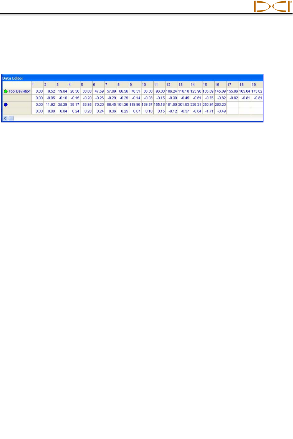
Changing Drill Data
Entering Tool’s Planned Deviation
Data Editor Table for Deviation Plot
}
}
Computer
Generated
Manually
Entered
The Data Editor table for the Deviation plot has numbered columns across the top of the table that cor-
respond to the locations where data will be or has been logged, as in the table for the Profile plot. Column
1 contains data for the first logged point; column 2 contains data for the second logged point, etc. Note
that the first column will always have 0.00 in each cell, because the first point recorded on an SST bore is
when the tool is ½ in the ground and ½ out of the ground—referred to as the zero, zero point.
The deviation table has only two plotted profiles—Tool Deviation and an unnamed blank field, which you
should name appropriately (see below). There are two rows of values for each of these plotted profiles—
the upper row gives the x-coordinate or horizontal distance from the launch point, and the lower row gives
the y-coordinate or the distance above or below the zero elevation line or x-axis.
¾ Tool Deviation – These x,y coordinates are computer generated automatically by the SST
system’s software when you log the bore—you will not enter any information in these two rows.
¾ Unnamed or Blank – The x,y coordinates for this field are based on the launch point position and
are manually entered prior to, during, or after the bore. If the planned deviation is to the right of
the launch point (below the x-axis), you must enter a “–” sign, if the planned deviation is to the left
of the launch point (above the x-axis), you do not have to enter a “+” sign.
Naming Blank Field for Deviation Plot
The unnamed plotted profile field is left blank so that you can name it appropriately for your job. DCI
suggests something like Planned Deviation or Planned Line. To name this blank field, place the cursor in
the cell and double-click, then type the desired name and hit enter.
Entering or Changing Data for Planned Deviation Plot
To enter or change values for the x,y coordinates in the deviation table, double-click on a value and then
type in the new value and hit enter.
50 Eclipse® SST® Operator’s Manual
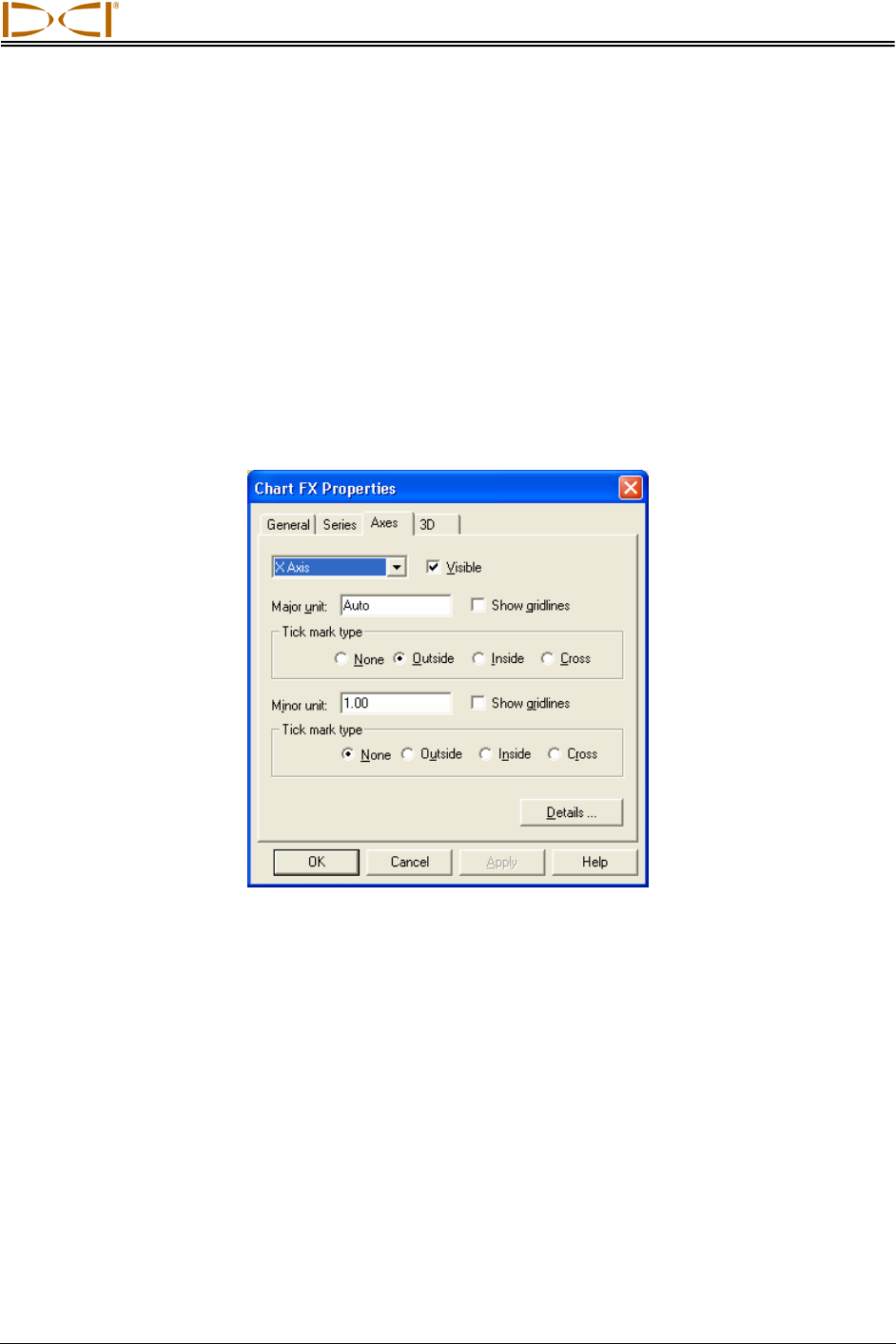
Changing Drill Data
Graphing Options
You can change the appearance of the Profile and Deviation plots in a variety of ways. The various
options that are available are discussed below. Some options will alter the appearance of both plots, and
some will only alter the plot in which you are working. Place your cursor in the plot area that you want to
change to open the Chart FX dialog box that affects that plot area.
Changing Appearance and Location of X and Y Axes
To change the appearance and location of the x- or y-axis in either the Profile or Deviation plot, place the
cursor in the desired plot area, and right click; then select Properties... from the popup menu to open the
Chart FX Properties dialog box. Select the Axes tab, as shown below.
Chart FX Properties Dialog Box – Axes Tab
Click on the top left field’s drop-down arrow and select the X or Y axis, then click the Details button at the
bottom of the dialog box to open the X or Y Axis Properties dialog box.
Eclipse® SST® Operator’s Manual 51
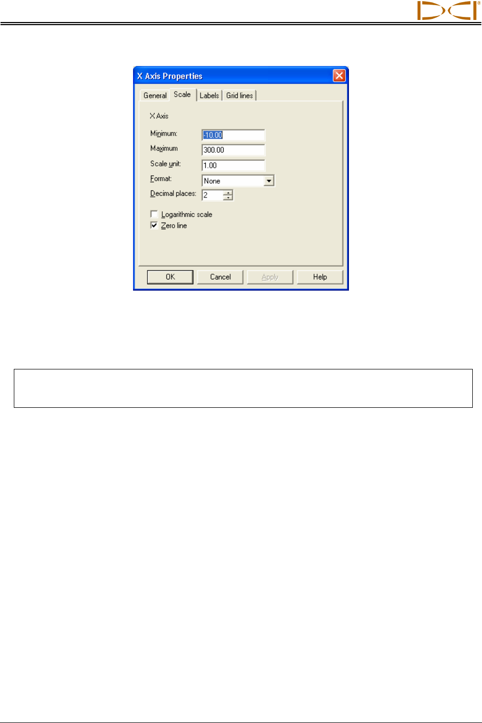
Changing Drill Data
X Axis Properties Dialog Box – Scale Tab
The Scale tab is automatically selected. Make the desired changes in the Minimum and Maximum boxes,
and click Apply. You will see the plots adjust accordingly. Click on OK or on the “X” in the upper right
corner of the Chart FX Properties dialog box to close it.
NOTE: The X Axis properties affect both the Profile and Deviation plots. The Y Axis Properties
affect only one plot. If you open the Chart FX properties from the Profile plot, changes
made in the Y Axis Properties box will only affect the Profile plot.
You may want to change the appearance of the plots to eliminate excess white space. Simple instructions
are given below for common changes you may want to make.
Change Vertical Scale (Move X-Axis Up or Down in Profile Plot)
1. Right mouse click in Profile plot area.
2. Select Properties... from popup menu.
3. Click on Axes tab in Chart FX Properties dialog box.
4. Select Y Axis in upper left field.
5. Click on Details button to open Y Axis Properties dialog box.
6. Under Scale tab (which is automatically selected), in the Minimum box, type in a negative value;
this defines the placement of the x-axis and, therefore, the amount of white space displayed
above and below the x-axis.
7. Type in a value for the Maximum; this represents the amount of white space displayed above the
x-axis.
8. Click on Apply to see the plot shift according to the values you have input.
9. Click on OK to exit dialog box, then on OK again to exit Chart FX dialog box.
52 Eclipse® SST® Operator’s Manual
Changing Drill Data
Change Horizontal Scale (Move Y-Axis to Left or Right in Profile Plot)
1. Right mouse click in Profile plot area.
2. Select Properties... from popup menu.
3. Click on Axes tab in Chart FX Properties dialog box.
4. Click on drop-down arrow in upper left field and select X Axis.
5. Click on Details button to open X Axis Properties dialog box.
6. Under Scale tab (which is automatically selected), in the Minimum box, type in a value, usually
negative, to move the y-axis to the left or right. A zero value will place the y-axis at the left edge
of the graph; a positive value will place the y-axis outside the graph area to the left.
7. Type in a value for the Maximum, which specifies the horizontal distance displayed. The ideal
number will be just a little greater than the borepath’s maximum x-distance, as displayed in the
xDist column in the Logged Data field.
8. Click on Apply to see the plot shift according to the values you have input.
9. Click on OK to exit dialog box, then on OK again to exit Chart FX dialog box.
Move Axes in Deviation Plot
1. Right mouse click in the Deviation plot area.
2. You will get the same series of dialog boxes as described above for the Profile plot area. Follow
the instructions given above to change the appearance of the Deviation plot.
Changing Appearance of Plotted Profiles
To change the color scheme used in the plotted profiles, open the Chart FX Properties dialog box in the
plot area you want to change, and click on the Series tab.
Chart FX Properties Dialog Box – Series Tab
Eclipse® SST® Operator’s Manual 53
Changing Drill Data
In the graphic above, the Series tab is selected and the drop-down list for the top left field is clicked to
display the four plots. Once one plot is selected, as shown below, the color, size, and shape of the line
and data points for that plot can be changed. After making changes, click the Apply button to see the
desired changes take effect.
Chart FX Properties Dialog Box – Selecting Plot to Edit
Drawing and Changing Objects on Plots
The annotate toolbar provides tools for drawing objects, importing artwork, or adding text to either the
Profile or Deviation plot. The annotate toolbar must be displayed to enable you to select an icon or
function. See “Plot Area Toolbars” in the Computer Instructions section for information on how to display
the annotate toolbar and descriptions of the icons or functions provided on the toolbar.
Annotate Toolbar:
Using the pointer , you can select an existing object. Moving the pointer or cursor over an object
changes it to a four-arrow cursor and allows you to select the object. Once selected, an object will
have a shaded line and handles (or little black squares) around it, and you will be able to drag the object
around or enlarge or reduce it.
When you have an object selected with the four-arrow cursor, you can click the right mouse button to
display a popup menu with more drawing options, including access to the Annotation Object Properties
dialog box. You can also access this dialog box, which allows more ways to edit the object, by double-
clicking the four-arrow cursor or by right clicking with the four-arrow cursor and then selecting Properties...
from the popup menu.
54 Eclipse® SST® Operator’s Manual
Changing Drill Data
Annotation Object Properties Dialog Box
The next four icons after the cursor allow you to draw rectangles , circles or ovals , lines with or
without arrowheads , and curved (arc) lines . These tools work in a similar manner to those
provided in drawing programs. To use them, click on the icon and then place the cursor where you want
to draw the item; click and hold in the mouse button as you drag the cursor to make the object the desired
size.
Next is the picture import icon , which allows you to import a graphic from another application. The
picture import function is not activated (does not function) in the current version of Steering Tool software.
Then the toolbar provides two text box tools. The first allows you to draw a plain text box . The second
allows you to draw a balloon with text in it . To draw either type of text box, select the desired icon,
and then place the cursor where you want the box and drag the cursor to make the object the desired
size in the desired location. Then double-click on the word “Text” that appears in the box and type in the
desired text.
The remainder of the tools on the annotate toolbar are standard drawing tools. Their functions are
explained under the description of the annotate toolbar under “Plot Area Toolbars” earlier in this section.
Eclipse® SST® Operator’s Manual 55

Changing Drill Data
Notes
56 Eclipse® SST® Operator’s Manual
DIGITAL CONTROL INCORPORATED
APPENDIX
Importing Topography, Drill Plan, and
Planned Deviation from Excel File
The SST software allows you to import topography, drill plan, and planned deviation data from a text file
created in Microsoft Excel. This should be done before you start logging your SST bore.
Create Text File
The file must be in the correct format for importing, as shown in the following figure. Each plot or set of
data (topography, drill plan, and planned deviation) spans two columns that list the x-coordinate in the
first column and the y-coordinate in the second column for each logged point.
First row
of data
Format for Data in Excel File
Eclipse® SST® Operator’s Manual 57
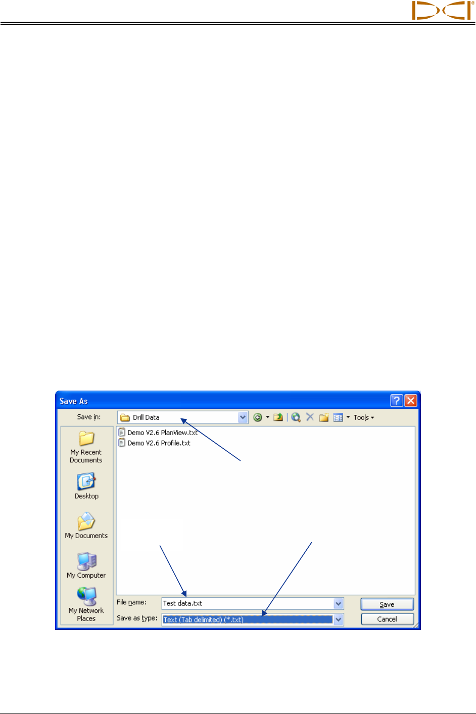
Appendix
The first row of data will always consist of zeroes. This is because the first logged point is recorded when
the SST transmitter (in the housing) is positioned so that it is ½ in and ½ out of the ground. This point is
measured as zero, or 0.0, for both the x- and y-coordinates.
Note that the x,y coordinate values must be in decimal format (not using fractions). For example, if you
want to enter 4 ft 8 in., then you will enter the value 4.67.
For each data plot, the x-coordinate value will give the distance from the start of the bore. The x-value will
be positive and will continue to increase from the start of the bore.
The y-coordinate value for the topography and drill plan plots will give the distance from the zero
elevation line or the x-axis. If the value is negative or below the zero elevation line, you must enter a “–”
sign in front of the value. You do not need to enter a “+” sign for a positive value.
The y-coordinate value for the planned deviation will also require a “–” sign in front of the value when the
Deviation plot is negative and goes below the x-axis.
Save Text File
Once you have input the information in the Excel spreadsheet, you need to save the file in the correct
format. The SST software requires a tab-delimited text file (*.txt) for import. Follow the steps given below
to save the data as a text file.
1. To save the file, select File | Save As on the menu bar to open the Save As dialog box.
Folder Where File
Will Be Saved
Type in
File Name Select File Type
Save As Dialog Box in Excel Application
2. In this dialog box, change the folder where you want to save the file at the top of the dialog box, if
necessary.
58 Eclipse® SST® Operator’s Manual
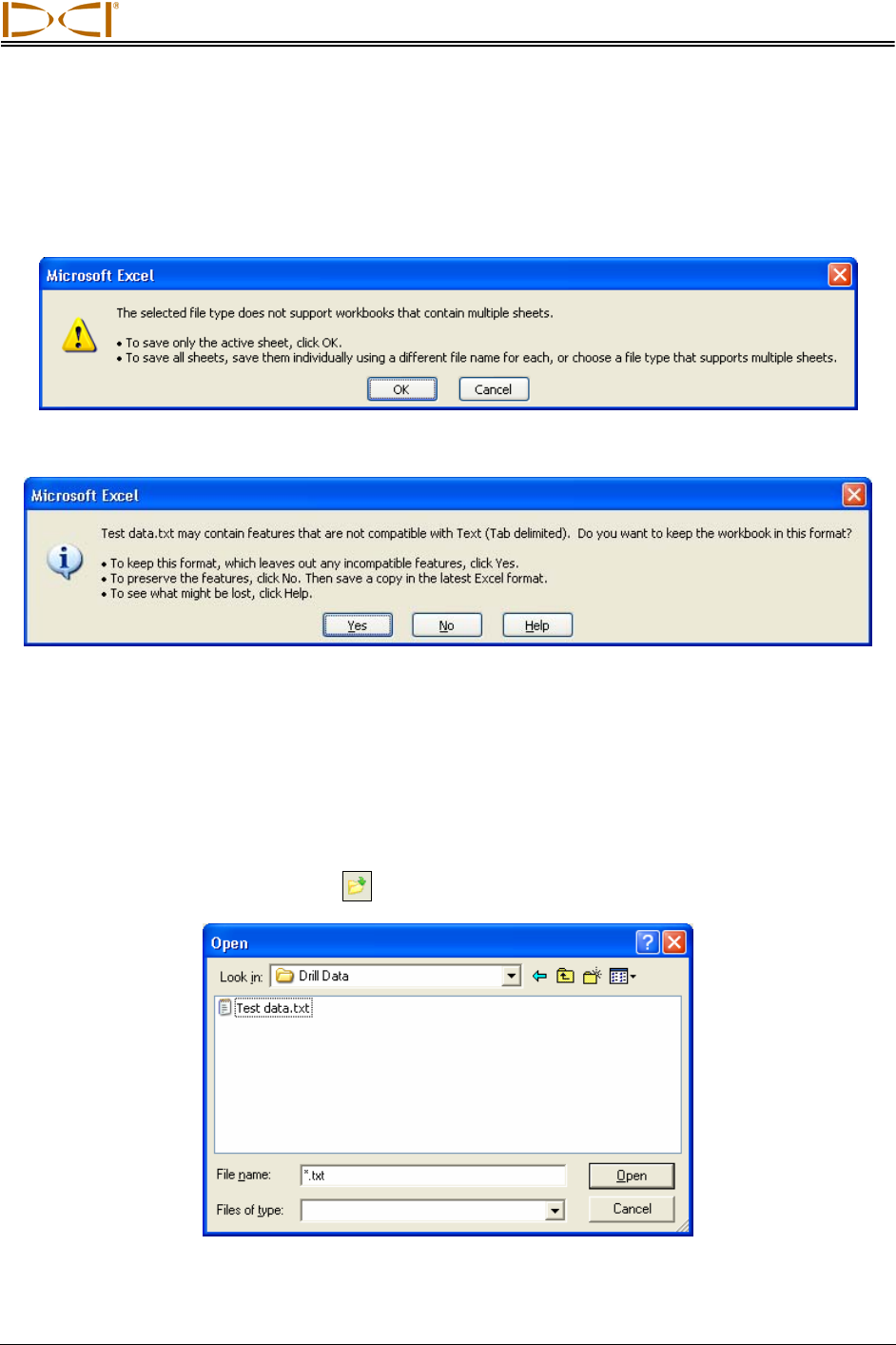
Appendix
3. Type in the desired file name where indicated at the bottom of the dialog box.
4. Then select the “Text (Tab delimited) (*.txt)” option in the “Save as type” drop-down box at the
bottom of the dialog box.
5. Click on Save. You will see the following dialog box:
6. Click OK. You will then see another dialog box appear as follows:
7. Click on Yes. The file has now been saved. In this example the file name is Test data.txt.
You can now exit the Excel application. You will see the same series of dialog boxes again; answer the
same as above and the application will then close.
Import Text File into SST Software
1. Open the SST software.
2. Click on the Import Topography icon in the standard toolbar to open the Open dialog box.
Open Dialog Box
Eclipse® SST® Operator’s Manual 59
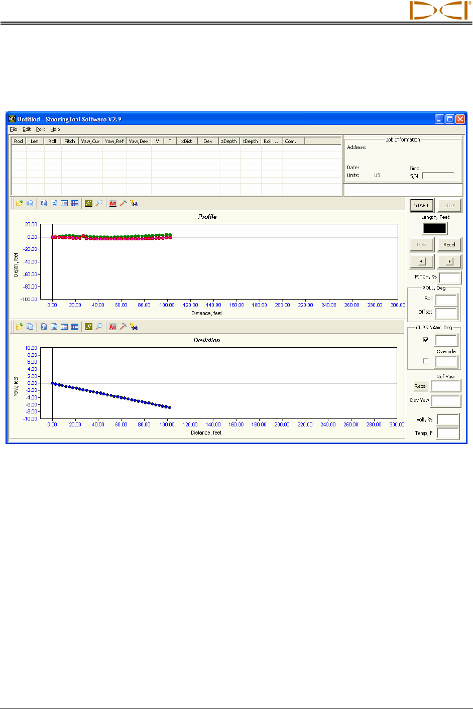
Appendix
3. Select the file, after navigating to the folder where you saved it if necessary.
4. Click the Open button. You should see the three plotted profiles in the plot area of the SST
application.
Import of Text File
5. You may need to adjust the scaling. For example, the plots in the graphic above are compressed
to the left of the plot area. See “Graphing Options” in the Inputting and Changing Drill Data
section of the manual for information on how to edit the plots. For example, the graphic below
shows how the plots look after adjusting the Y Axis properties.
60 Eclipse® SST® Operator’s Manual
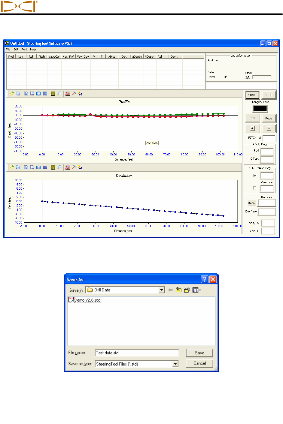
Appendix
Appearance of Plots After Making Graphic Changes
6. You should save the data after it is in the desired format. To save, select the File | Save menu
command to open the Save As dialog box.
Save As Dialog Box in SST Application
You have now saved the data as a Steering Tool file.
Eclipse® SST® Operator’s Manual 61

Appendix
62 Eclipse® SST® Operator’s Manual
Notes
3-1200-00-D

19625 62nd Ave. S., Suite B-103 y Kent, WA 98032 USA y (425) 251-0559 OR (800) 288-3610 y FAX (253) 395-2800
www.digitrak.com (Web Site) dci@digital-control.com (E-mail)
3-1200-00-D Page 1 of 2
DIGITAL
CONTROL
INCORPORATED
LIMITED WARRANTY
Digital Control Incorporated (“DCI”) warrants that when shipped from DCI each DCI product (“DCI Product”) will
conform to DCI’s current published specifications in existence at the time of shipment and will be free, for the
warranty period (“Warranty Period”) described below, from defects in materials and workmanship. The limited
warranty described herein (“Limited Warranty”) is not transferable, shall extend only to the first end-user (“User”)
purchasing the DCI Product from either DCI or a dealer expressly authorized by DCI to sell DCI Products
(“Authorized DCI Dealer”), and is subject to the following terms, conditions and limitations:
1. A Warranty Period of twelve (12) months shall apply to the following new DCI Products: receivers/locators,
remote displays, battery chargers and rechargeable batteries, and DataLog® modules and interfaces. A Warranty
Period of ninety (90) days shall apply to all other new DCI Products, including transmitters, accessories, and
software programs and modules. Unless otherwise stated by DCI, a Warranty Period of ninety (90) days shall
apply to: (a) a used DCI Product sold either by DCI or by an Authorized DCI Dealer who has been expressly
authorized by DCI to sell such used DCI Product; and (b) services provided by DCI, including testing, servicing,
and repairing an out-of-warranty DCI Product. The Warranty Period shall begin from the later of: (i) the date of
shipment of the DCI Product from DCI, or (ii) the date of shipment (or other delivery) of the DCI Product from an
Authorized DCI Dealer to User.
2. DCI's sole obligation under this Limited Warranty shall be limited to either repairing, replacing, or adjusting, at
DCI's option, a covered DCI Product that has been determined by DCI, after reasonable inspection, to be
defective during the foregoing Warranty Period. All warranty inspections, repairs and adjustments must be
performed either by DCI or by a warranty claim service authorized in writing by DCI. All warranty claims must
include proof of purchase, including proof of purchase date, identifying the DCI Product by serial number.
3. The Limited Warranty shall only be effective if: (i) within fourteen (14) days of receipt of the DCI
Product, User mails a fully-completed Product Registration Card to DCI; (ii) User makes a reasonable
inspection upon first receipt of the DCI Product and immediately notifies DCI of any apparent defect; and
(iii) User complies with all of the Warranty Claim Procedures described below.
WHAT IS NOT COVERED
This Limited Warranty excludes all damage, including damage to any DCI Product, due to: failure to follow DCI’s
user’s manual and other DCI instructions; abuse; misuse; neglect; accident; fire; flood; Acts of God; improper
applications; connection to incorrect line voltages and improper power sources; use of incorrect fuses;
overheating; contact with high voltages or injurious substances; or other events beyond the control of DCI. This
Limited Warranty does not apply to any equipment not manufactured or supplied by DCI nor, if applicable, to any
damage or loss resulting from use of any DCI Product outside the designated country of use. By accepting a DCI
Product and not returning it for a refund within thirty (30) days of purchase, User agrees to the terms of this
Limited Warranty, including without limitation the Limitation of Remedies and Liability described below, and
agrees to carefully evaluate the suitability of the DCI Product for User's intended use and to thoroughly read and
strictly follow all instructions supplied by DCI (including any updated DCI Product information which may be
obtained at the above DCI website). In no event shall this Limited Warranty cover any damage arising during
shipment of the DCI Product to or from DCI.
User agrees that the following will render the above Limited Warranty void: (i) alteration, removal or tampering
with any serial number, identification, instructional, or sealing labels on the DCI Product, or (ii) any unauthorized
disassembly, repair or modification of the DCI Product. In no event shall DCI be responsible for the cost of or any
damage resulting from any changes, modifications, or repairs to the DCI Product not expressly authorized in
writing by DCI, and DCI shall not be responsible for the loss of or damage to the DCI Product or any other
equipment while in the possession of any service agency not authorized by DCI.

3-1200-00-D Page 2 of 2
DCI reserves the right to make changes in design and improvements upon DCI Products from time to time, and
User understands that DCI shall have no obligation to upgrade any previously manufactured DCI Product to
include any such changes.
The foregoing Limited Warranty is DCI’s sole warranty and is made in place of all other warranties, express or
implied, including but not limited to the implied warranties of merchantability and fitness for a particular purpose
and any implied warranty arising from course of performance, course of dealing, or usage of trade. If DCI has
substantially complied with the warranty claim procedures described below, such procedures shall constitute
User’s sole and exclusive remedy for breach of the Limited Warranty.
LIMITATION OF REMEDIES AND LIABILITY
In no event shall DCI nor anyone else involved in the creation, production, or delivery of the DCI Product
be liable for any damages arising out of the use or inability to use the DCI Product, including but not
limited to indirect, special, incidental, or consequential damages or for any cover, loss of information,
profit, revenue or use based upon any claim by User for breach of warranty, breach of contract,
negligence, strict liability, or any other legal theory, even if DCI has been advised of the possibility of
such damages. In no event shall DCI’s liability exceed the amount User has paid for the DCI Product. To
the extent that any applicable law does not allow the exclusion or limitation of incidental, consequential
or similar damages, the foregoing limitations regarding such damages shall not apply.
This Limited Warranty gives you specific legal rights, and you may also have other rights which vary from state to
state. This Limited Warranty shall be governed by the laws of the State of Washington.
WARRANTY CLAIM PROCEDURES
1. If you are having problems with your DCI Product, you must first contact the Authorized DCI Dealer where it
was purchased. If you are unable to resolve the problem through your Authorized DCI Dealer, contact DCI’s
Customer Service Department in Kent, Washington, USA at the above telephone number between 6:00 a.m. and
6:00 p.m. Pacific Time and ask to speak with a customer service representative. (The above “800” number is
available for use only in the USA and Canada.) Prior to returning any DCI Product to DCI for service, you must
obtain a Return Merchandise Authorization (RMA) number. Failure to obtain a RMA may result in delays or return
to you of the DCI Product without repair.
2. After contacting a DCI customer service representative by telephone, the representative will attempt to assist
you in troubleshooting while you are using the DCI Product during actual field operations. Please have all related
equipment available together with a list of all DCI Product serial numbers. It is important that field troubleshooting
be conducted because many problems do not result from a defective DCI Product, but instead are due to either
operational errors or adverse conditions occurring in the User’s drilling environment.
3. If a DCI Product problem is confirmed as a result of field troubleshooting discussions with a DCI customer
service representative, the representative will issue a RMA number authorizing the return of the DCI Product and
will provide shipping directions. You will be responsible for all shipping costs, including any insurance. If, after
receiving the DCI Product and performing diagnostic testing, DCI determines the problem is covered by the
Limited Warranty, required repairs and/or adjustments will be made, and a properly functioning DCI Product will
be promptly shipped to you. If the problem is not covered by the Limited Warranty, you will be informed of the
reason and be provided an estimate of repair costs. If you authorize DCI to service or repair the DCI Product, the
work will be promptly performed and the DCI Product will be shipped to you. You will be billed for any costs for
testing, repairs and adjustments not covered by the Limited Warranty and for shipping costs. In most cases,
repairs are accomplished within 1 to 2 weeks.
4. DCI has a limited supply of loaner equipment available. If loaner equipment is required by you and is available,
DCI will attempt to ship loaner equipment to you by overnight delivery for your use while your equipment is being
serviced by DCI. DCI will make reasonable efforts to minimize your downtime on warranty claims, limited by
circumstances not within DCI’s control. If DCI provides you loaner equipment, your equipment must be received
by DCI no later than the second business day after your receipt of loaner equipment. You must return the loaner
equipment by overnight delivery for receipt by DCI no later than the second business day after your receipt of the
repaired DCI Product. Any failure to meet these deadlines will result in a rental charge for use of the loaner
equipment for each extra day the return of the loaner equipment to DCI is delayed.