Digital Control Z1920 ET, ST, LT, LT2 User Manual Operating Instructions
Digital Control Inc ET, ST, LT, LT2 Operating Instructions
UserManual.wiki
>
Digital Control
>
Z1920 User Manual
>
User Manual Eclipse
Contents
1.
User Manual Eclipse
2.
User Manual LT2
3.
User Manual LT
4.
User Manual SE
User Manual Eclipse
Navigation menu
Upload a User Manual
Namespaces
Wiki Guide
HTML
PDF
Info
Views
User Manual
Discussion / Help
Navigation

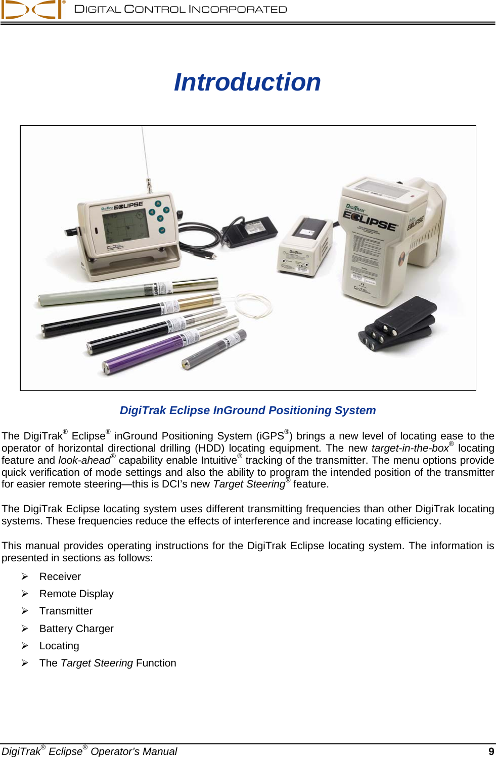
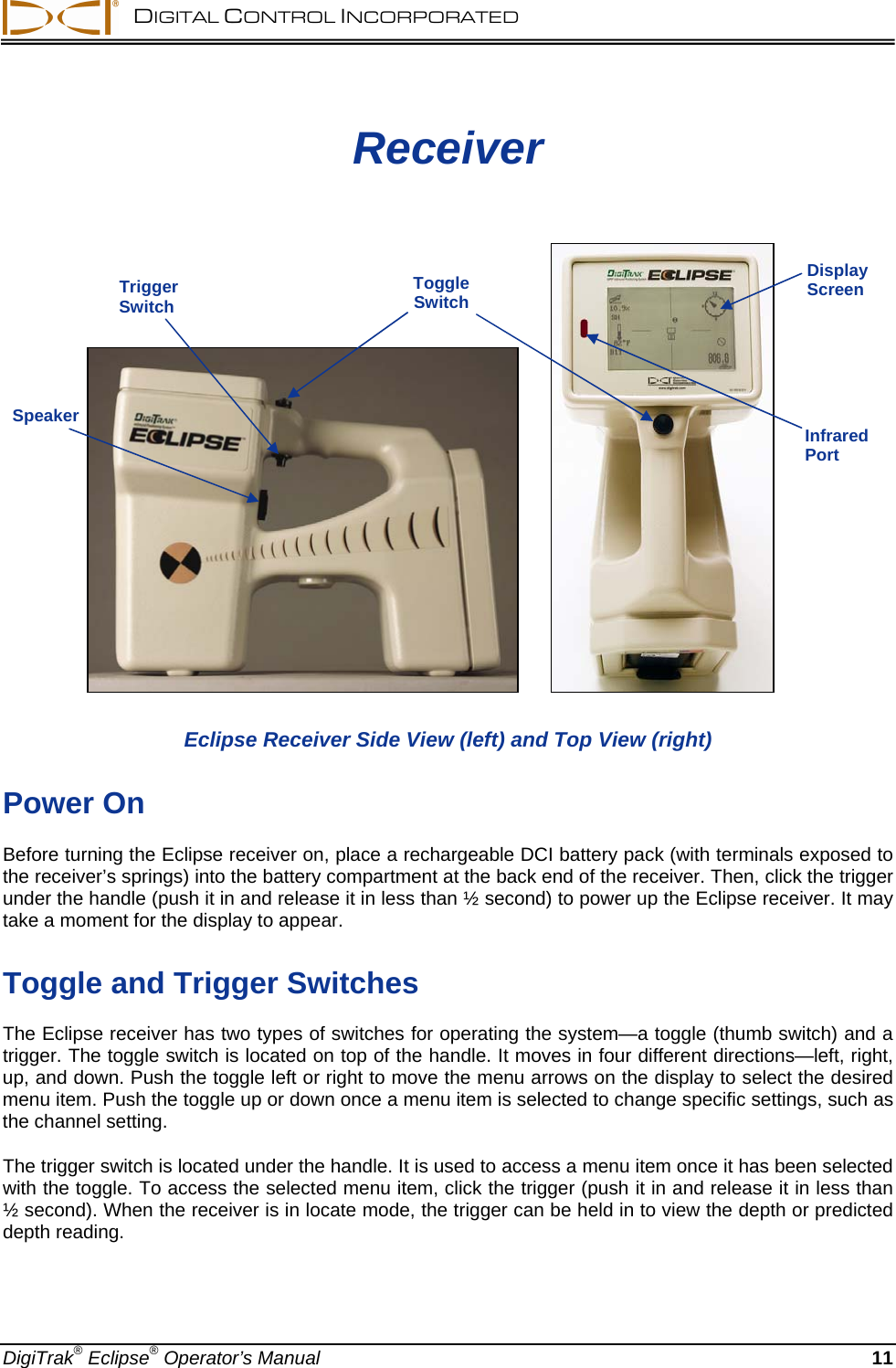
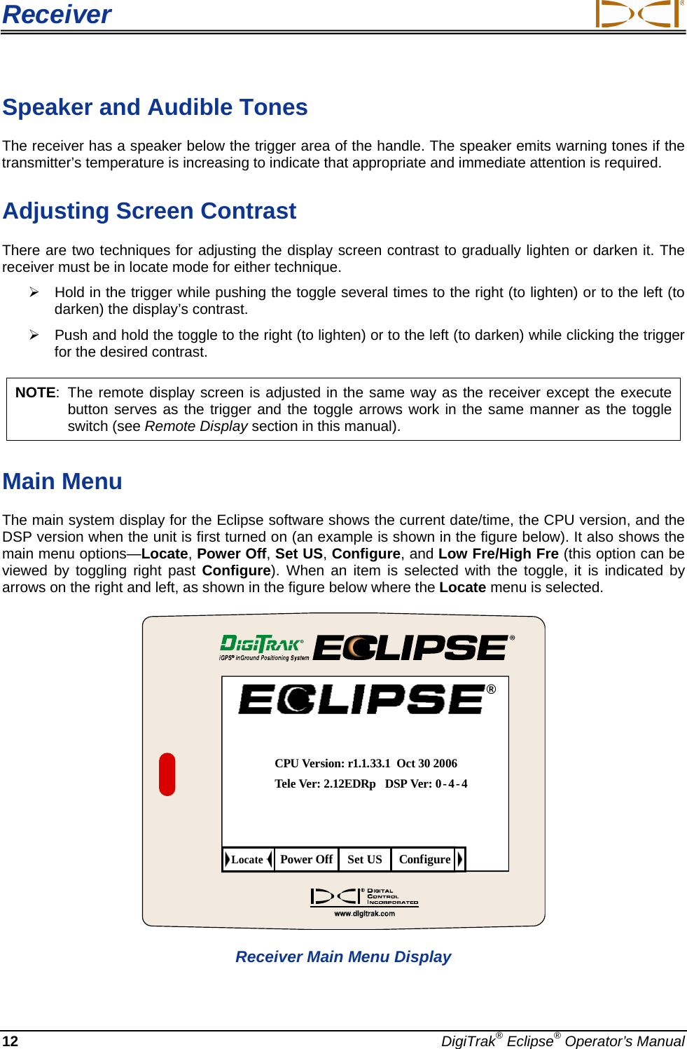
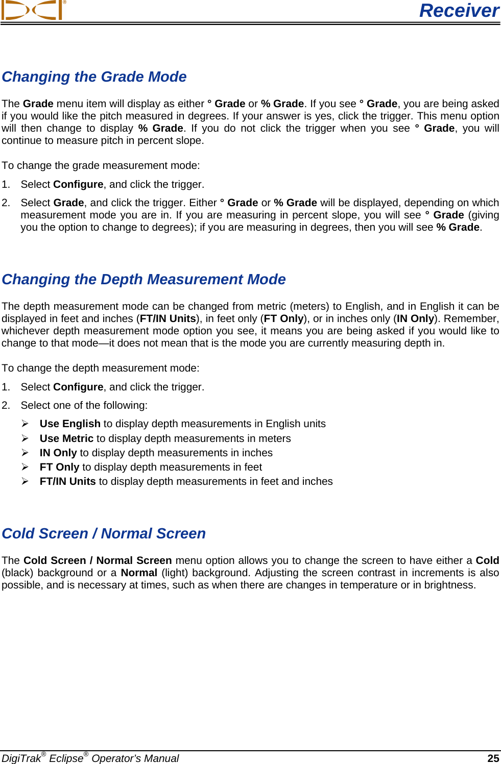
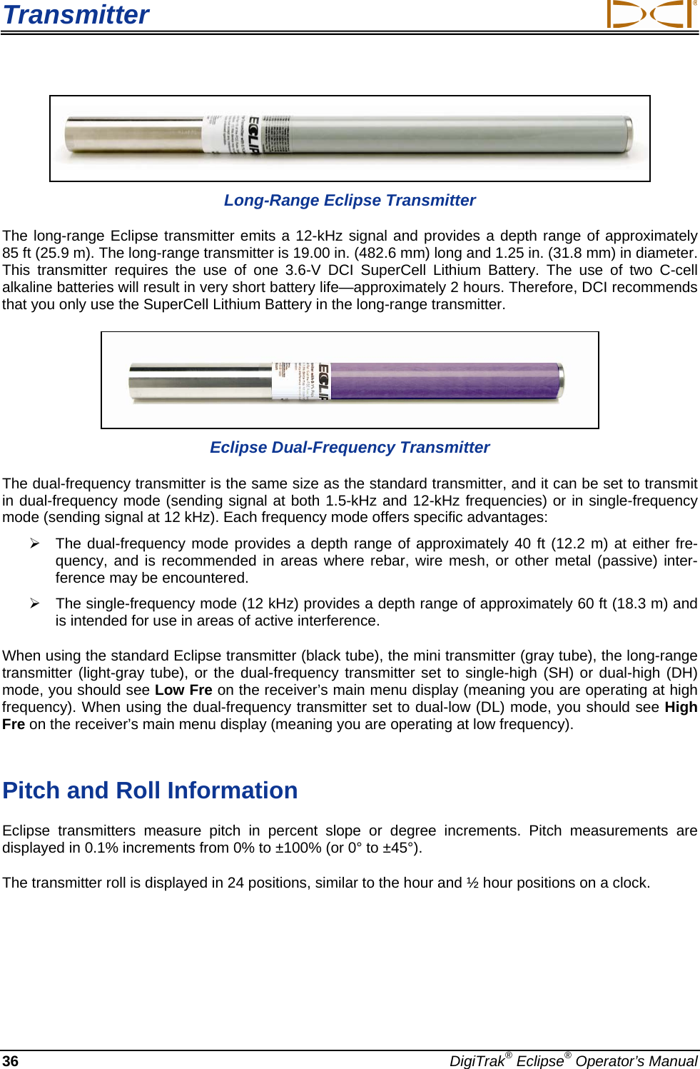
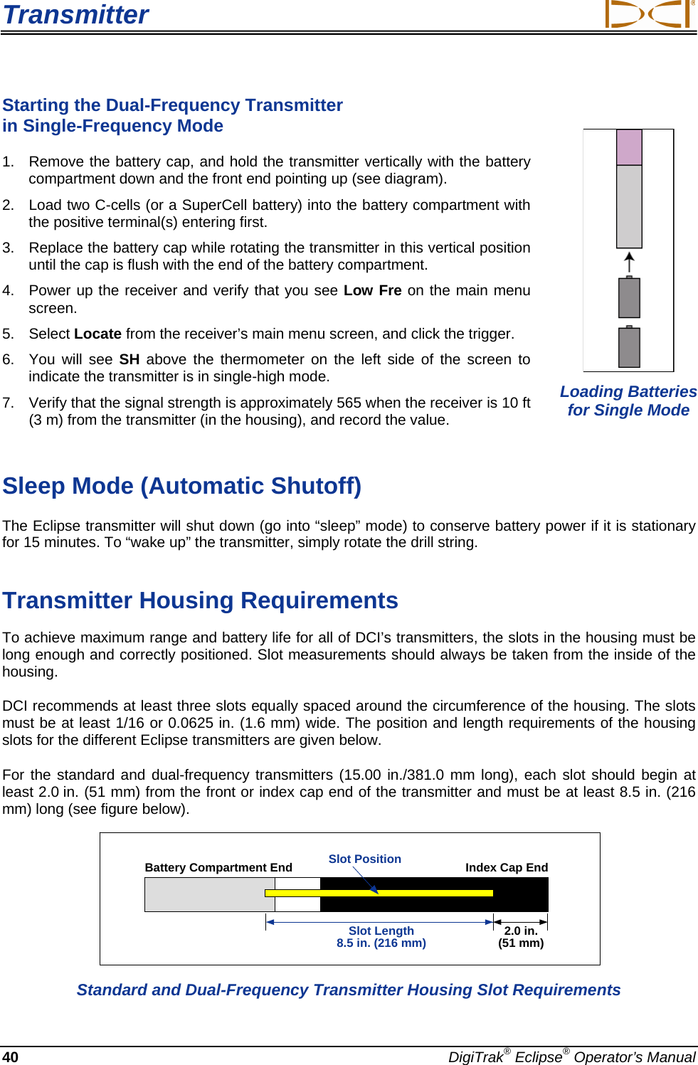
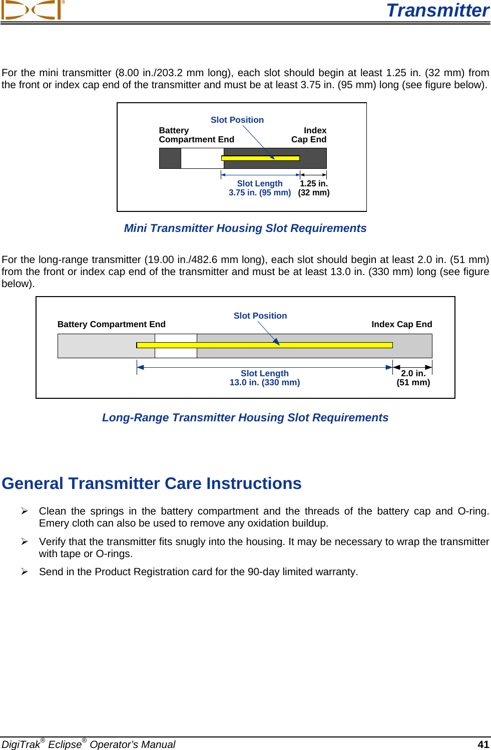
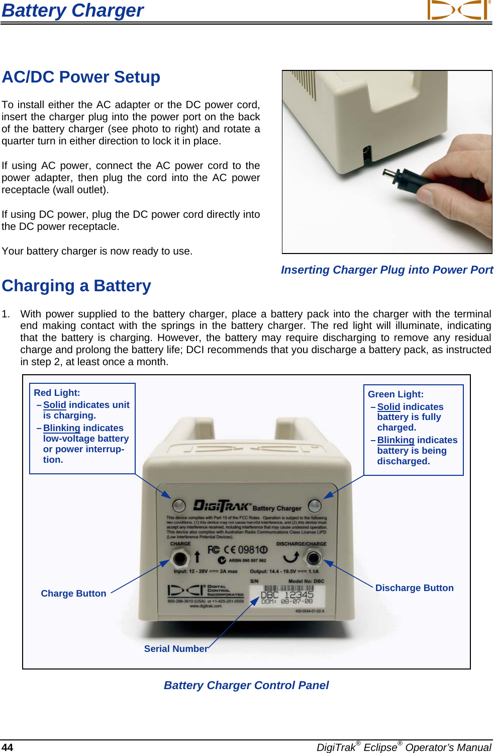
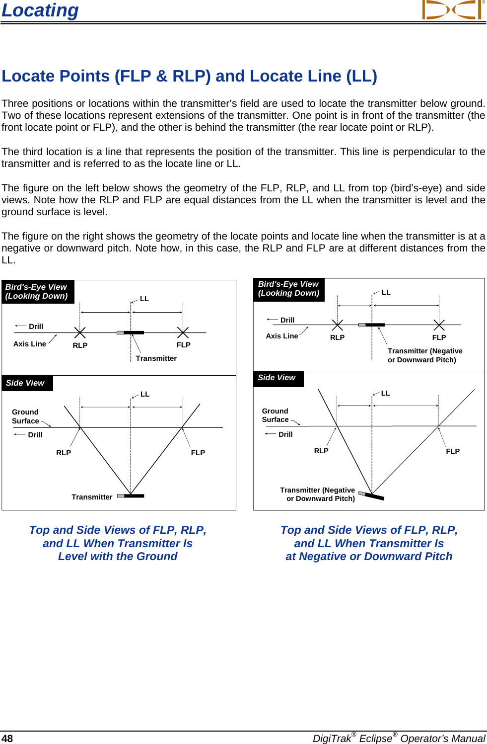
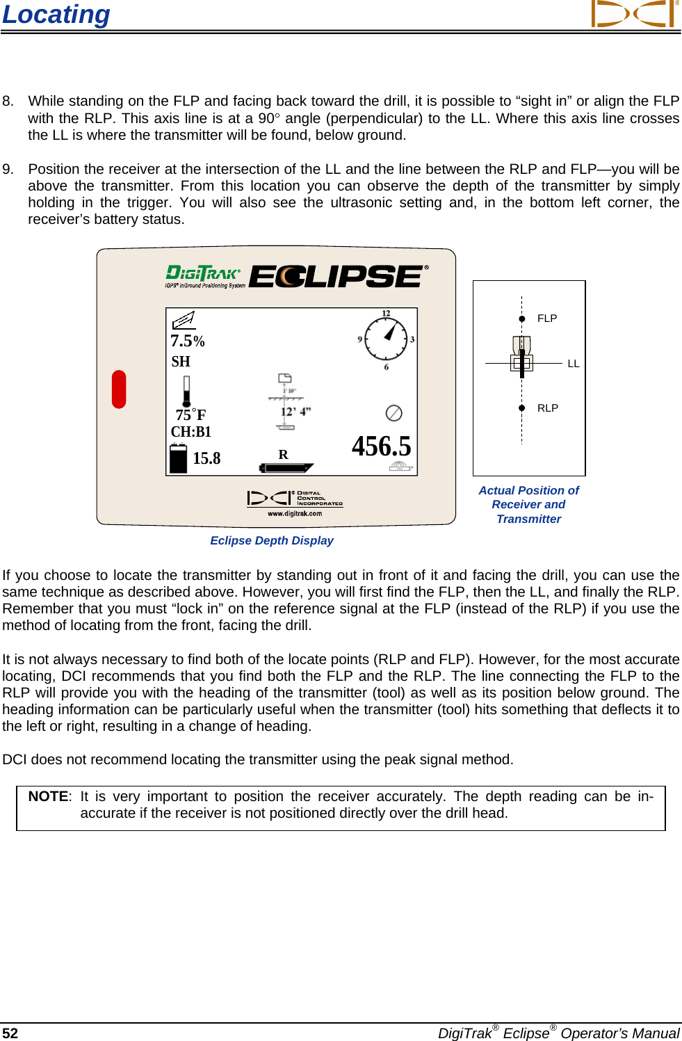
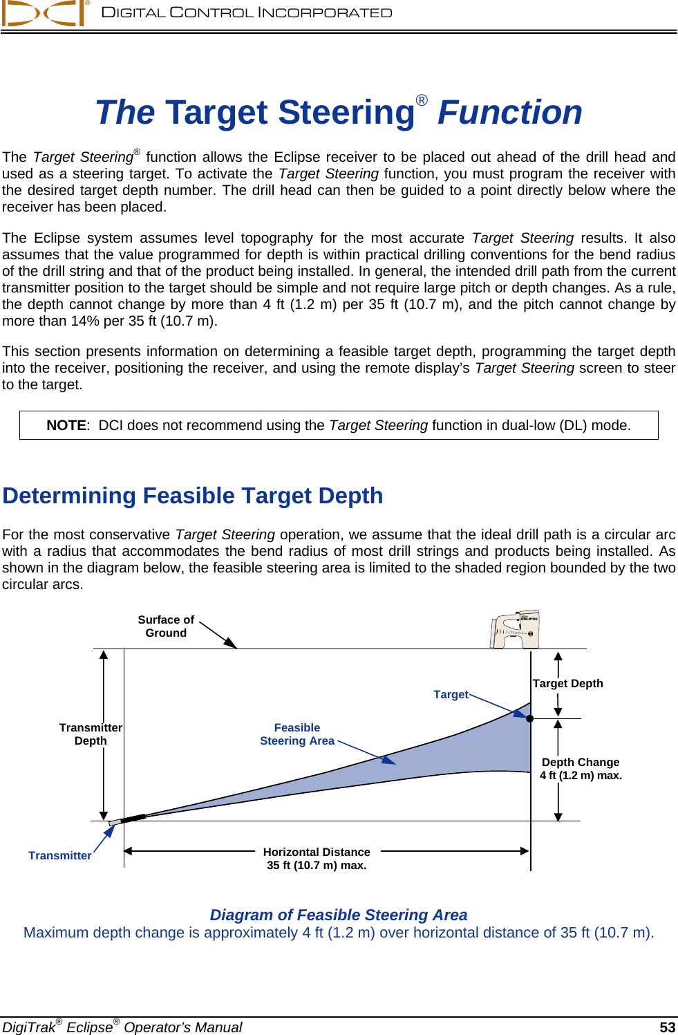
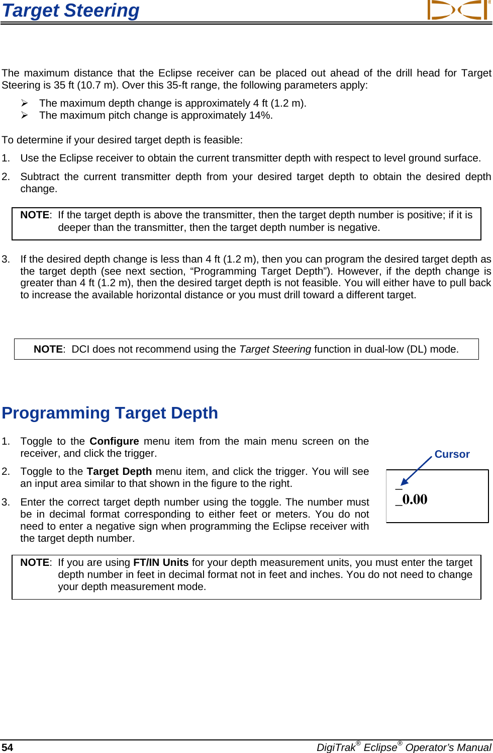
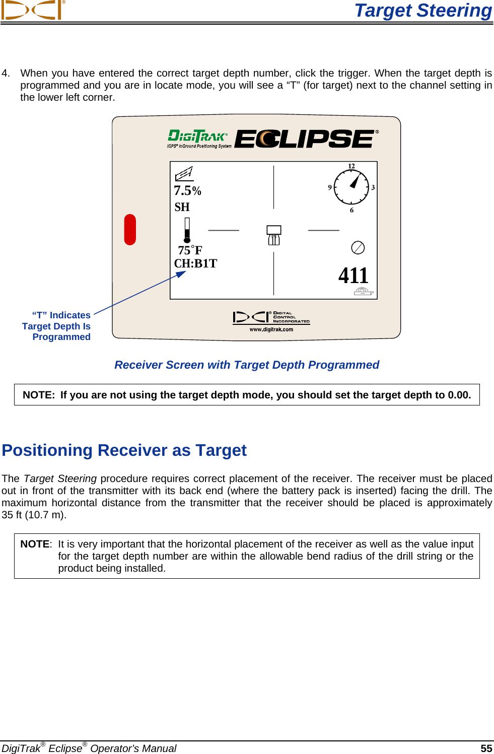
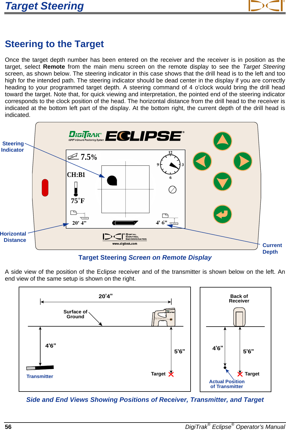
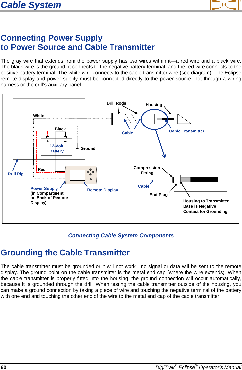
![DIGITAL CONTROL INCORPORATED Transmitter Types of Eclipse Transmitters DCI manufactures four different battery-operated Eclipse transmitters—a standard transmitter (black tube), a short-range mini transmitter (gray tube), a long-range transmitter (light-gray tube), and a dual-frequency transmitter (lavender tube). We also offer a cable transmitter (see Cable System section for information on the cable transmitter). For especially difficult locating jobs, such as when walkover locating is not possible, DCI offers the SST wireline transmitter, which is part of the Eclipse SST advanced HDD guidance system. For deep auger-boring applications, we offer a 60-in. (1524-mm) auger-boring cable transmitter that can be tracked for line and precision grade down to 200 ft (61 m). Call DCI or visit www.digitrak.com for more information on these products. The standard Eclipse transmitter emits a 12-kHz signal and provides a depth range of approximately 50 ft (15.2 m). The standard transmitter is 15.00 in. (381.0 mm) long and 1.25 in. (31.8 mm) in diameter. Standard Eclipse Transmitter The short-range mini transmitter emits a 12-kHz signal and provides a depth range of approximately 15 ft (4.6 m). The mini transmitter is 8.00 in. (203.2 mm) long and 1.00 in. (25.4 mm) in diameter. DCI offers an adapter for the mini transmitter to fit in a standard-sized housing. The outer dimensions of the adapter with the mini transmitter inside are exactly the same as those of the standard and dual-frequency transmitters (15.00 in. x 1.25 in. [381.0 mm x 31.8 mm]). Call DCI for additional information. Mini Eclipse Transmitter Mini Eclipse Transmitter with Housing Adapter DigiTrak® Eclipse® Operator’s Manual 35](https://usermanual.wiki/Digital-Control/Z1920.User-Manual-Eclipse/User-Guide-1349523-Page-35.png)