Digital Control Z1920 ET, ST, LT, LT2 User Manual Operating Instructions
Digital Control Inc ET, ST, LT, LT2 Operating Instructions
UserManual.wiki
>
Digital Control
>
Z1920 User Manual
>
User Manual SE
Contents
1.
User Manual Eclipse
2.
User Manual LT2
3.
User Manual LT
4.
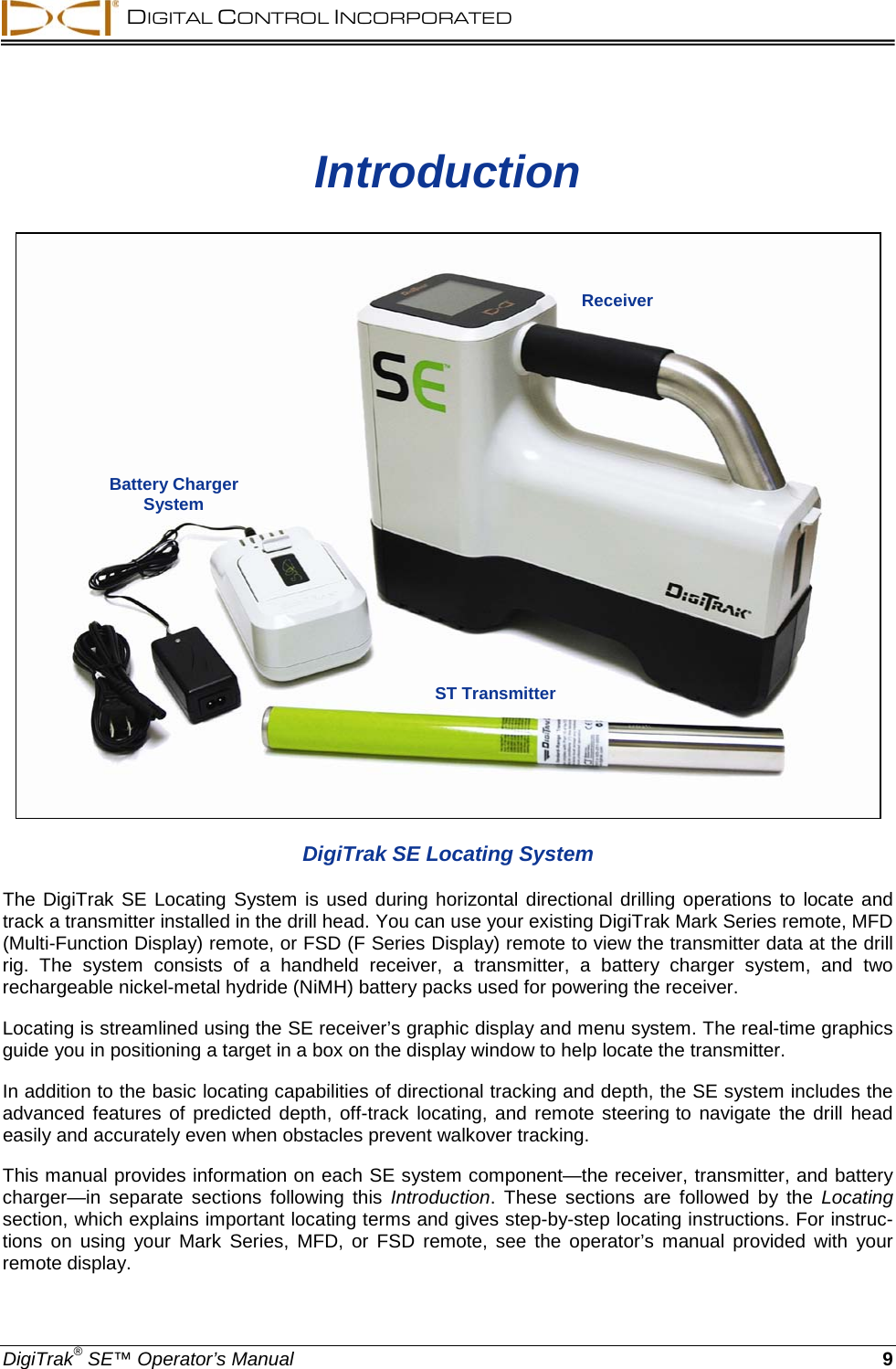
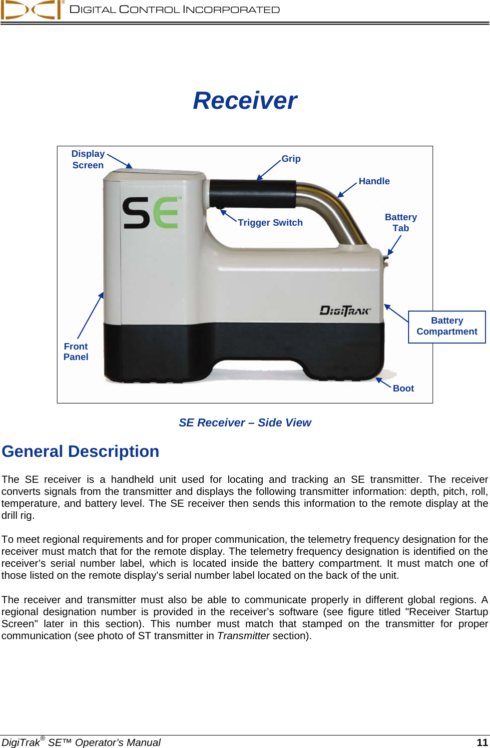
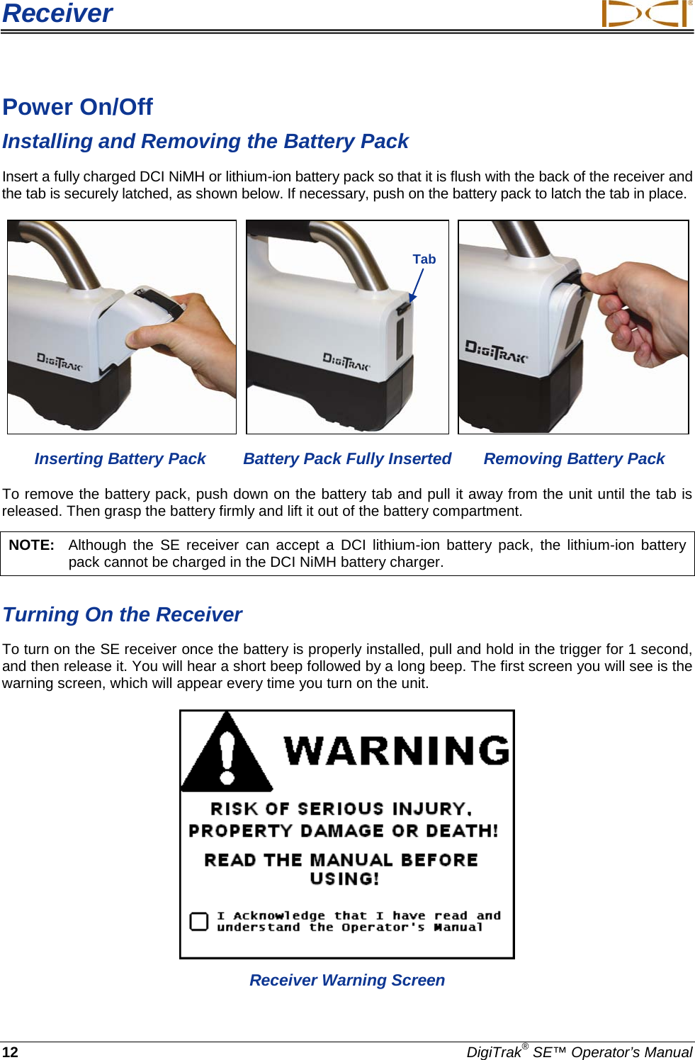
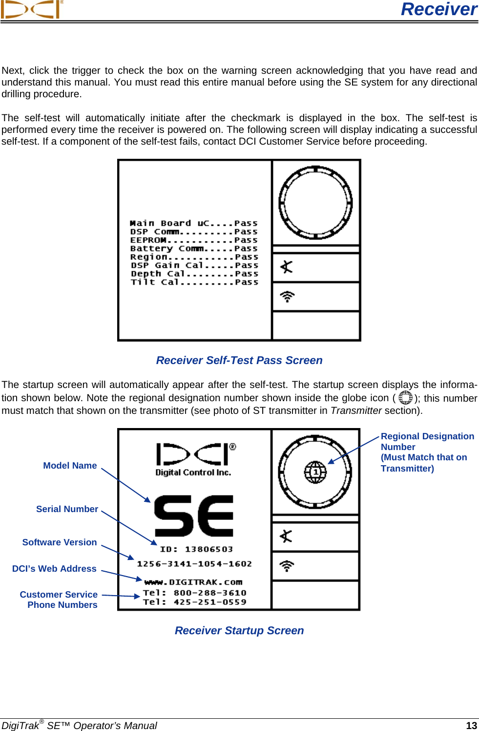
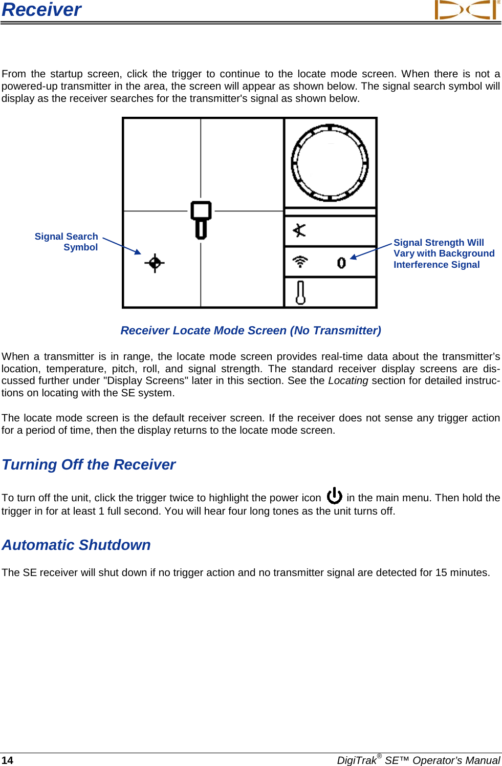
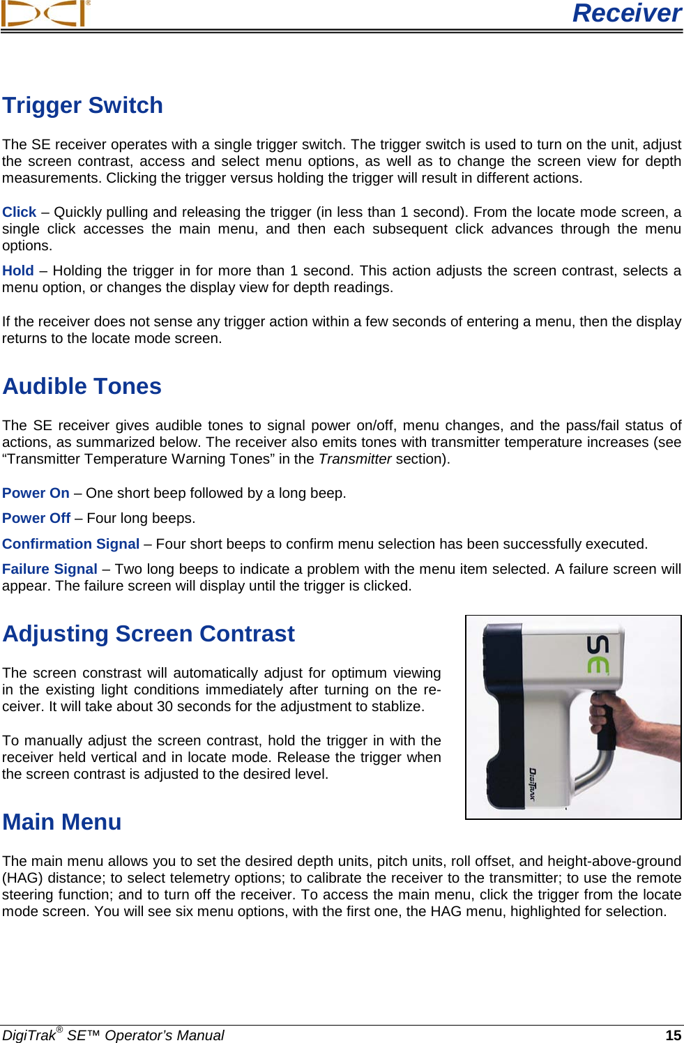
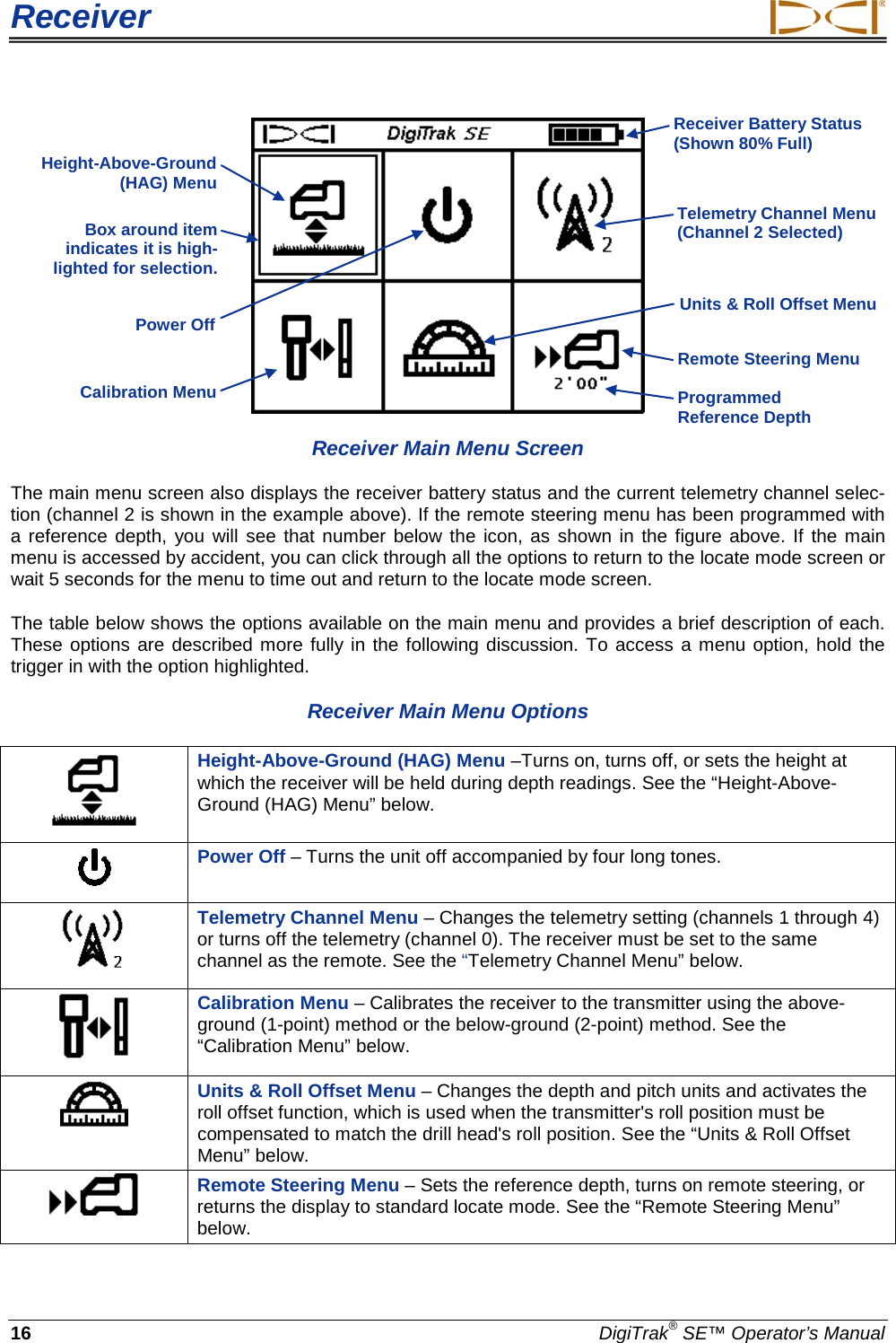
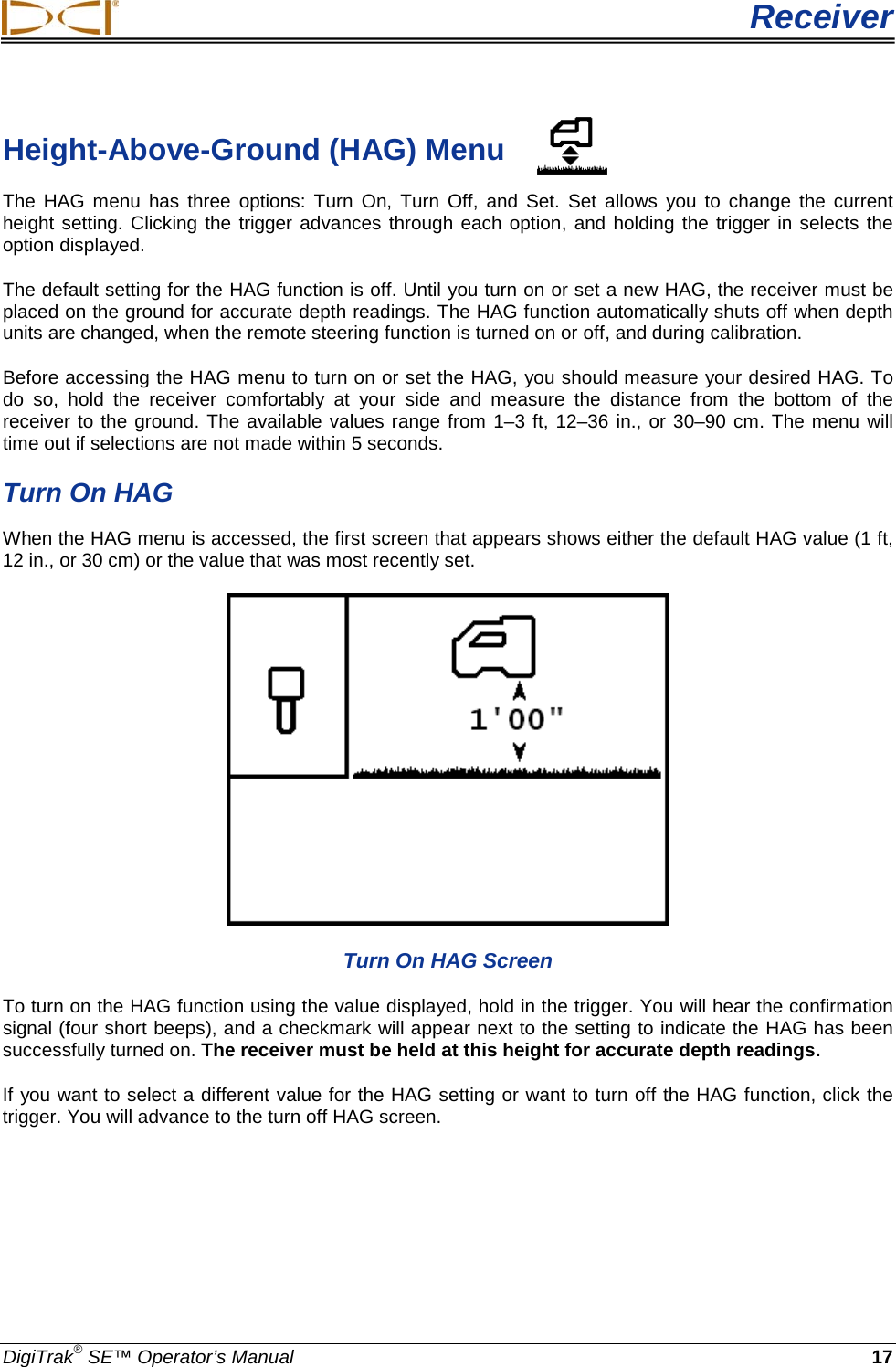
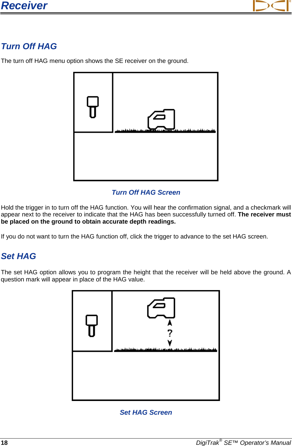
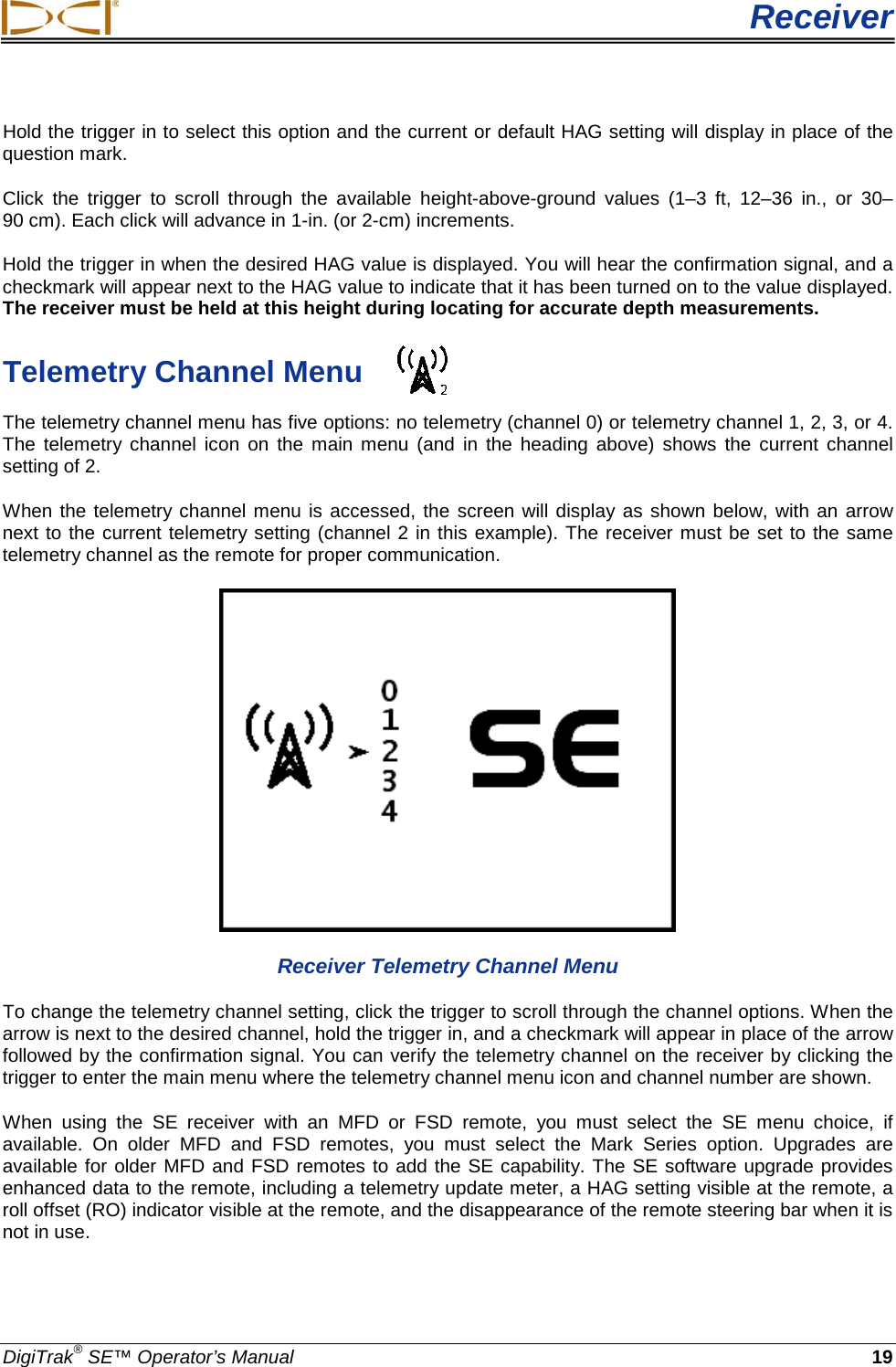
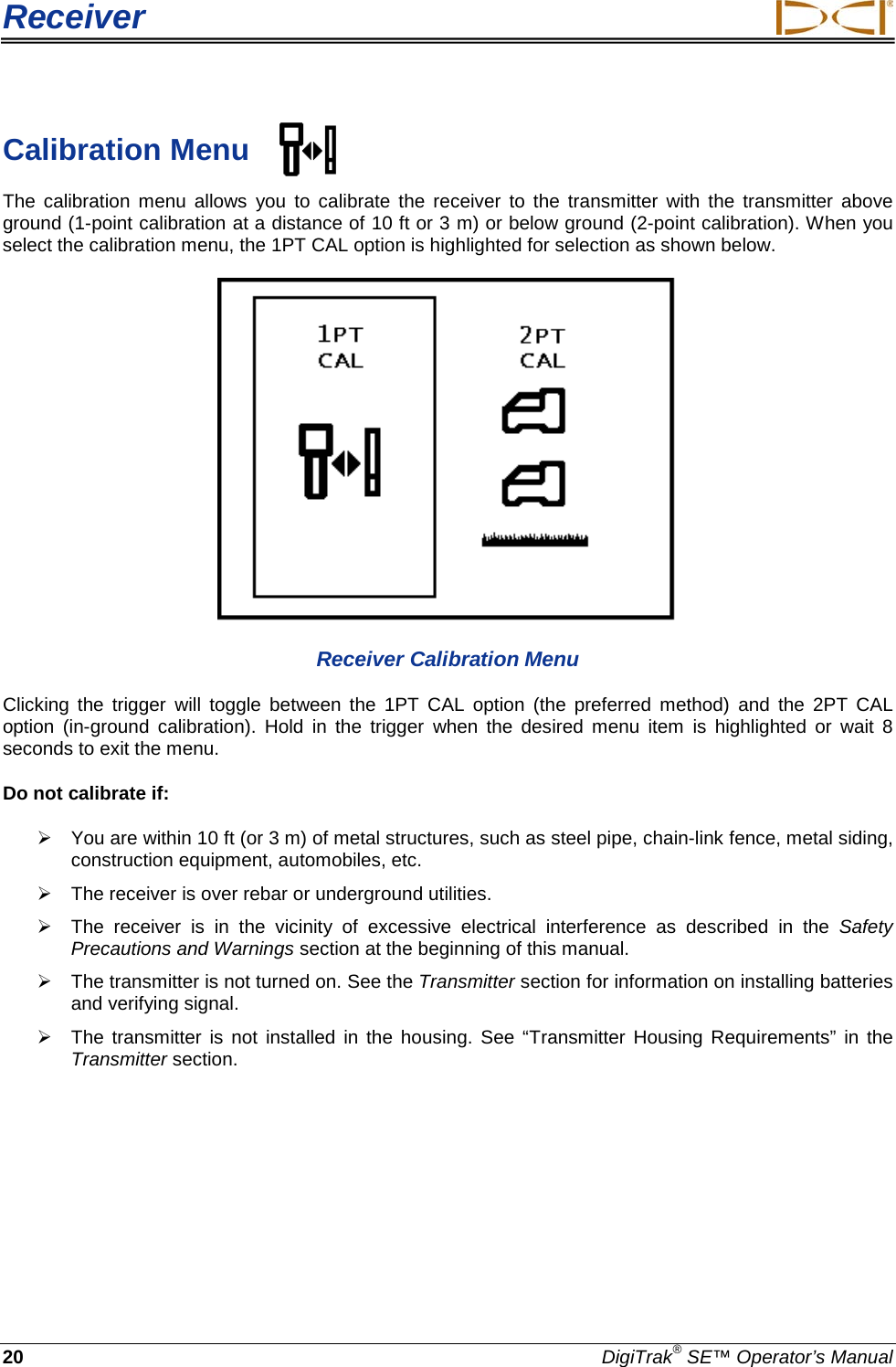
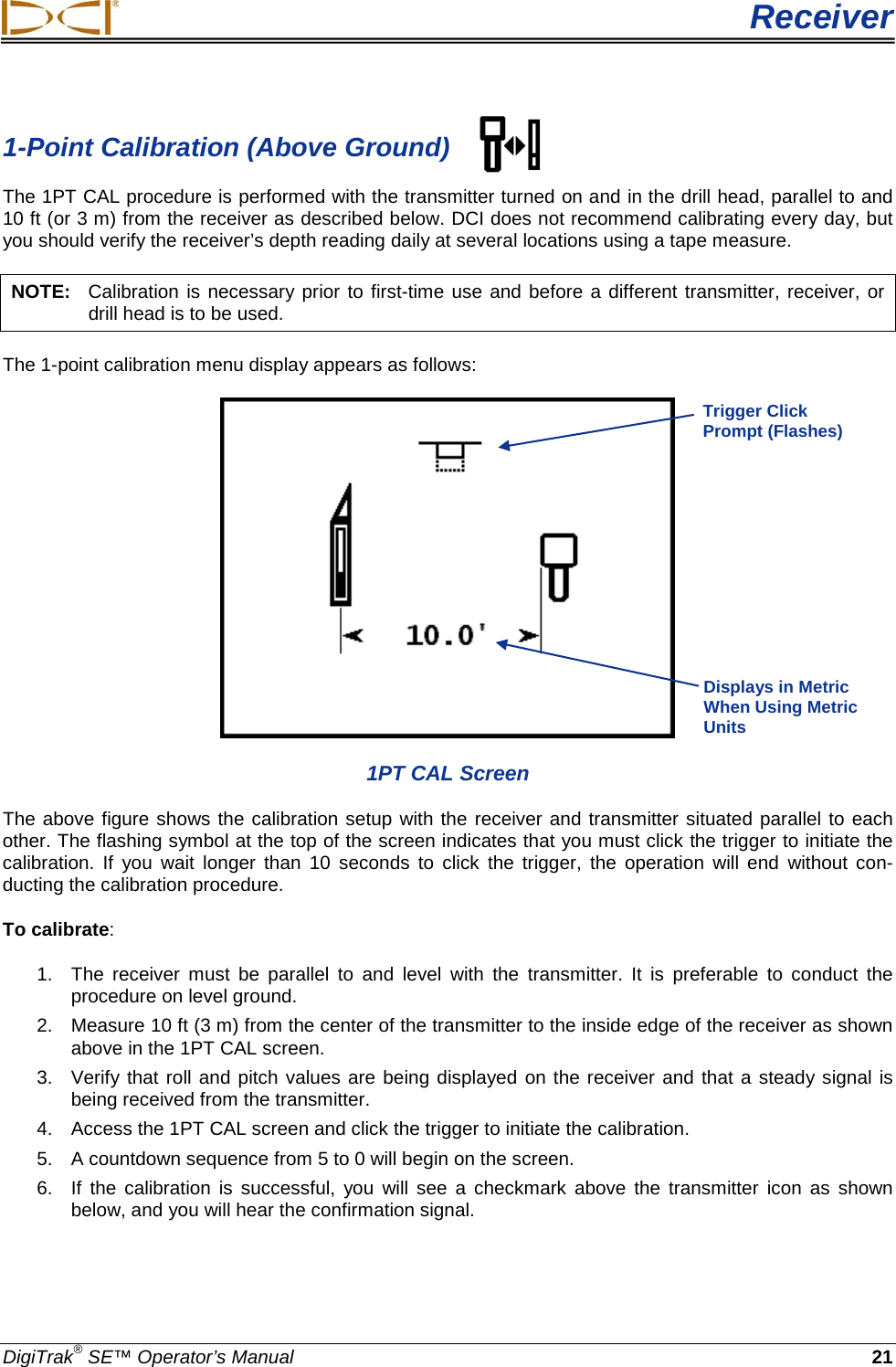
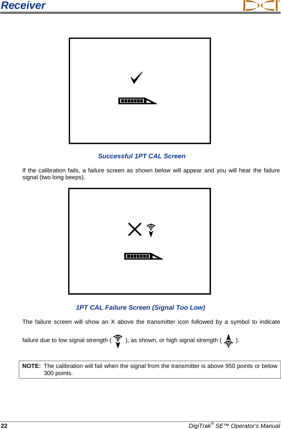
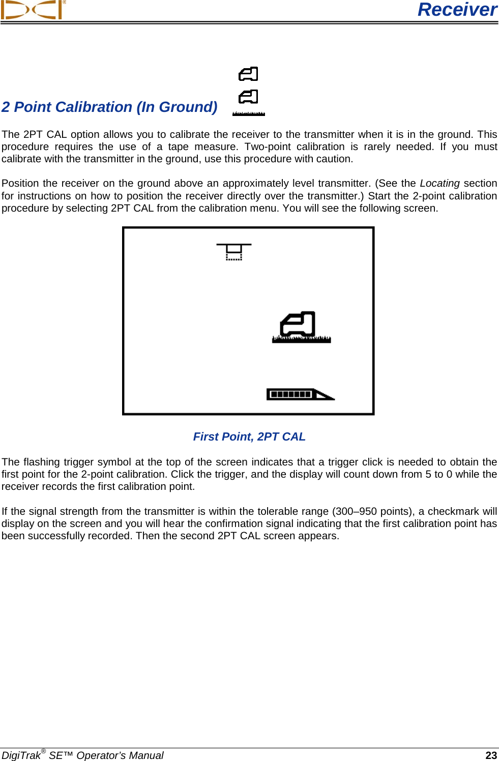
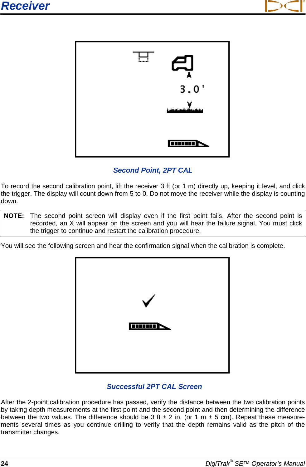
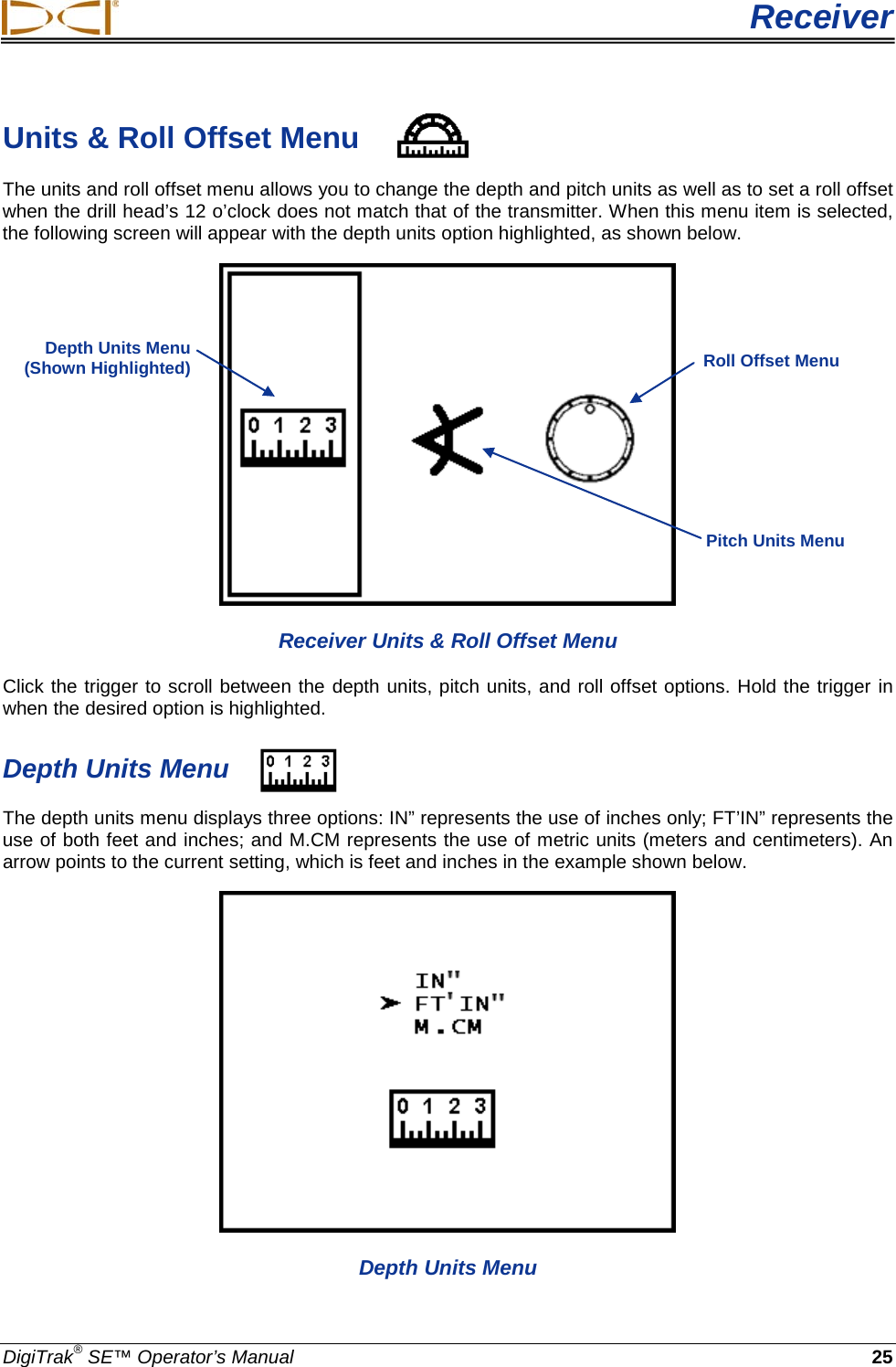
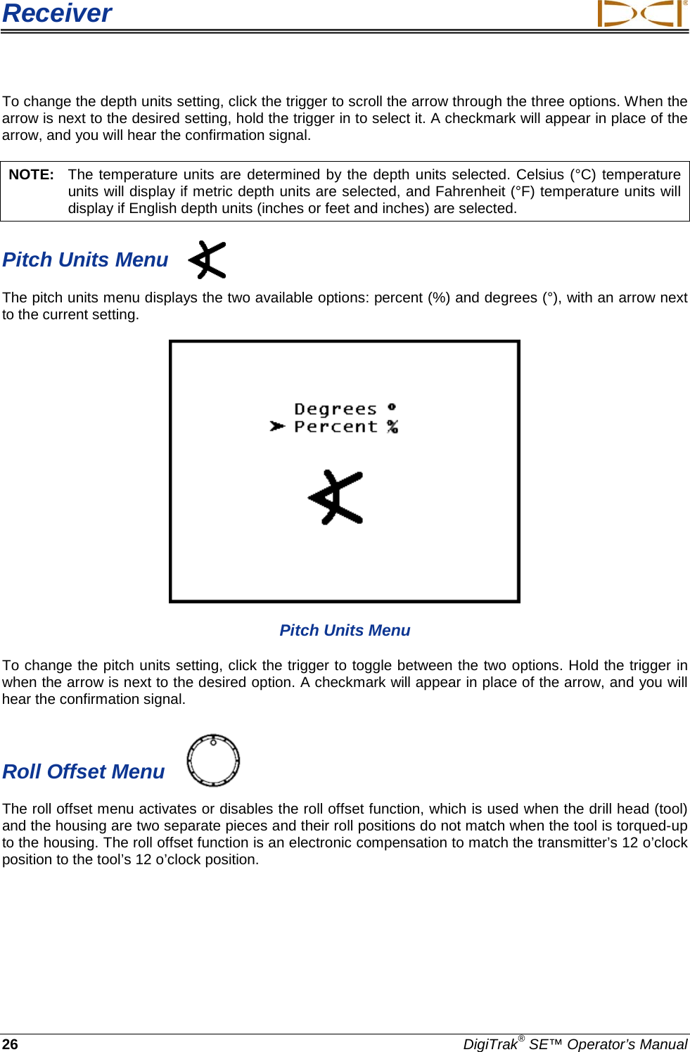
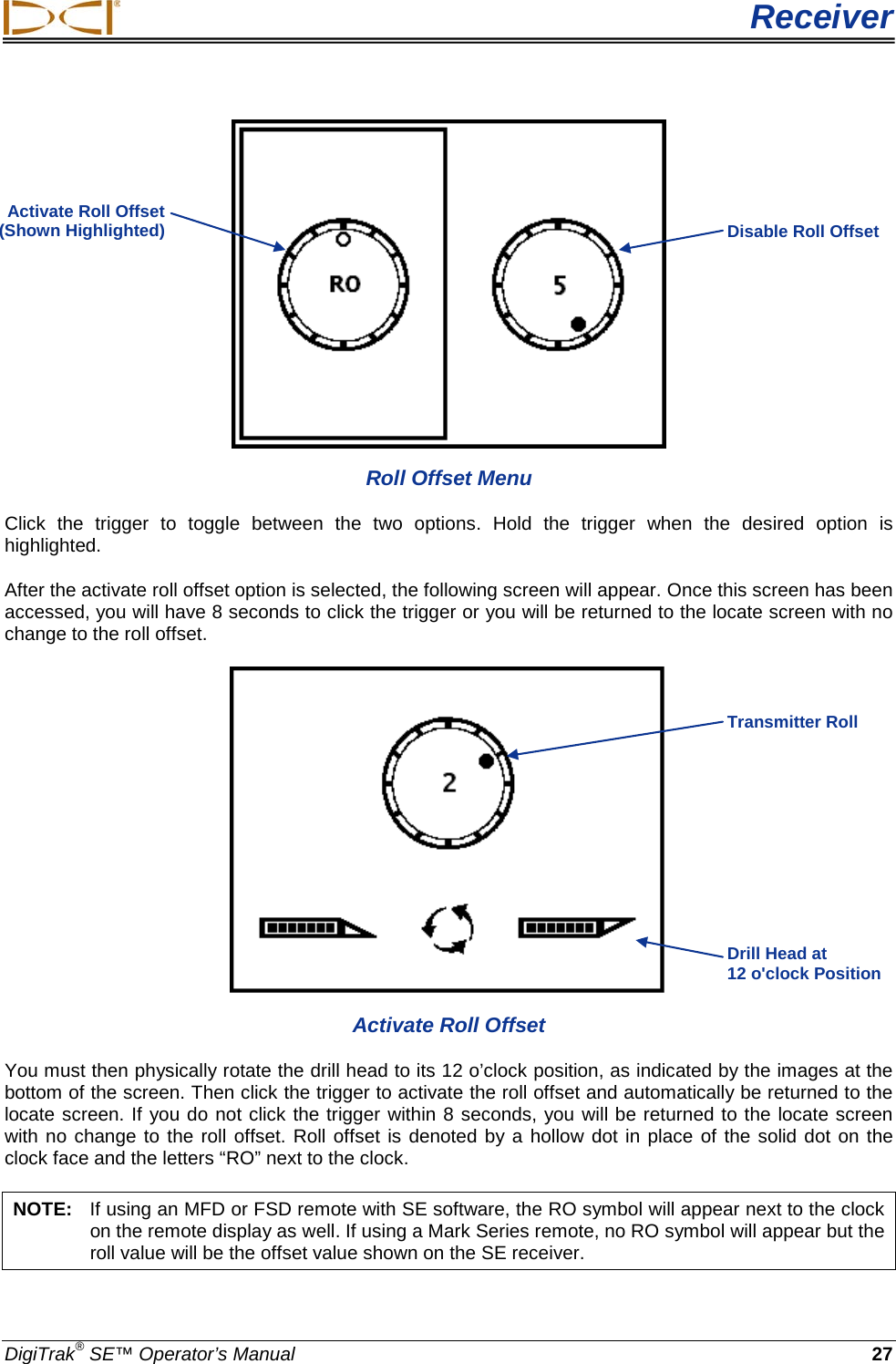
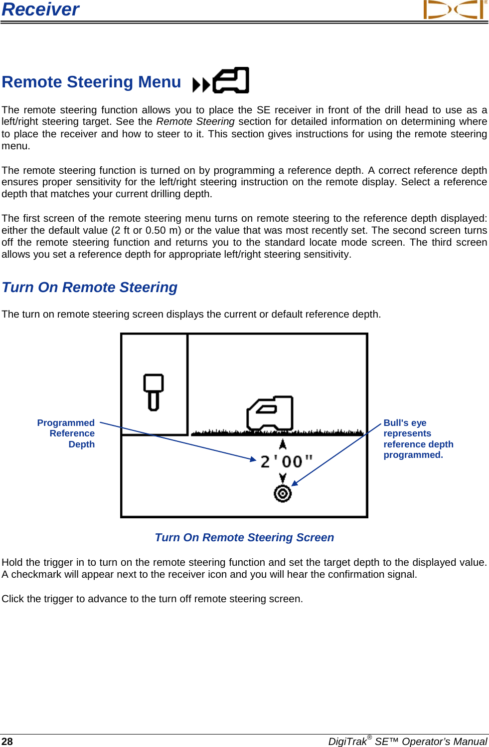
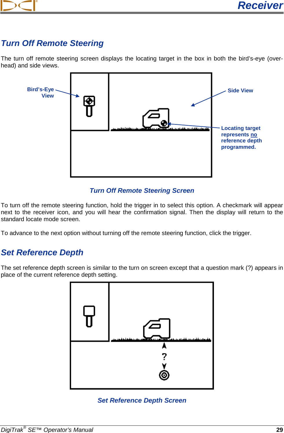
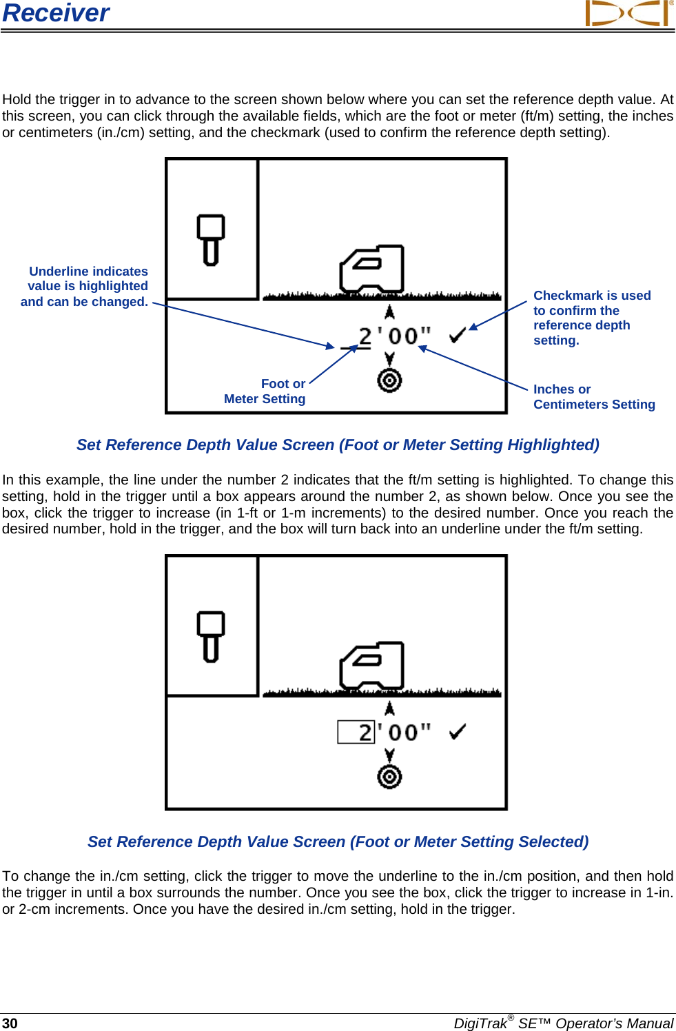
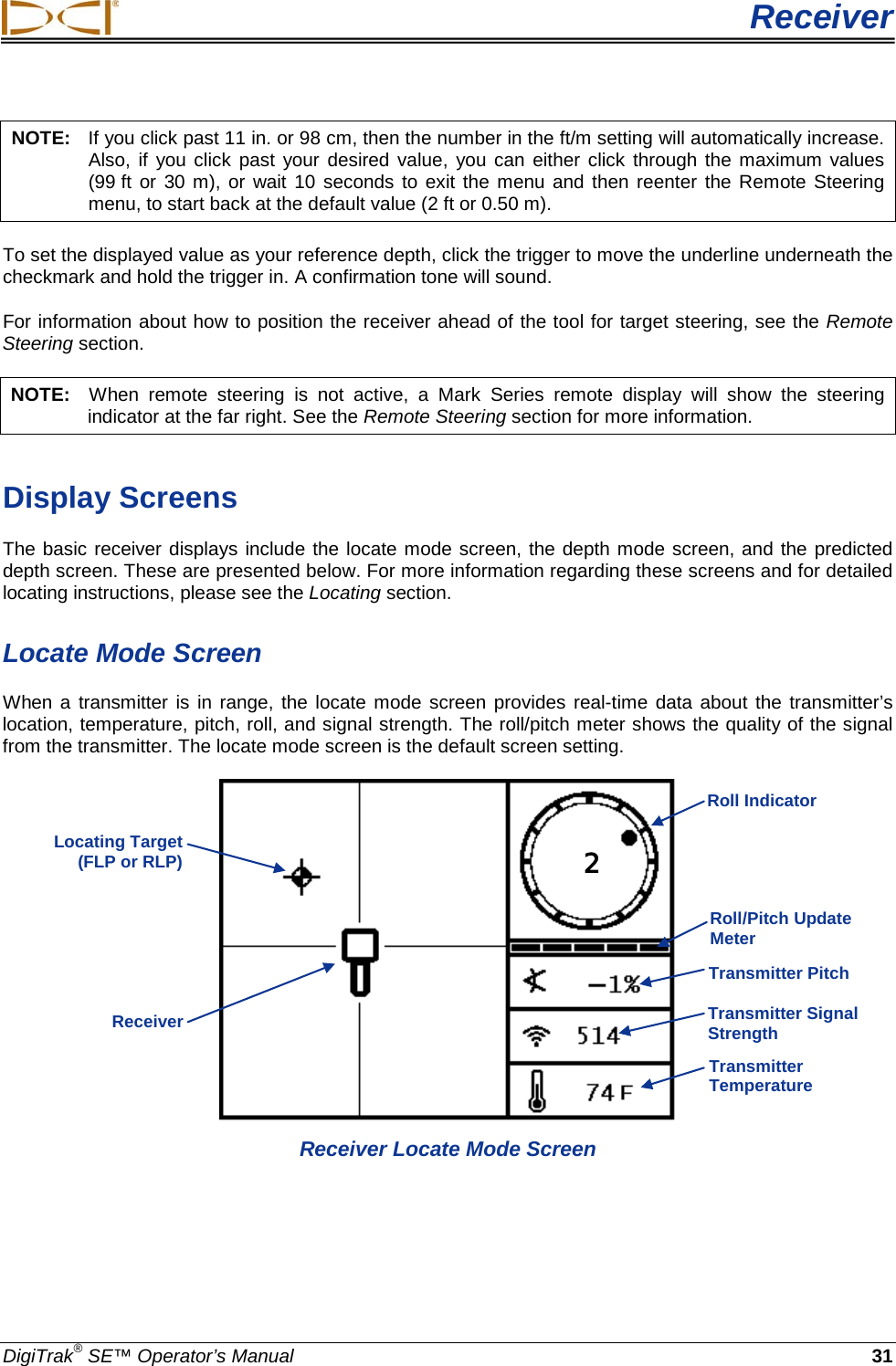
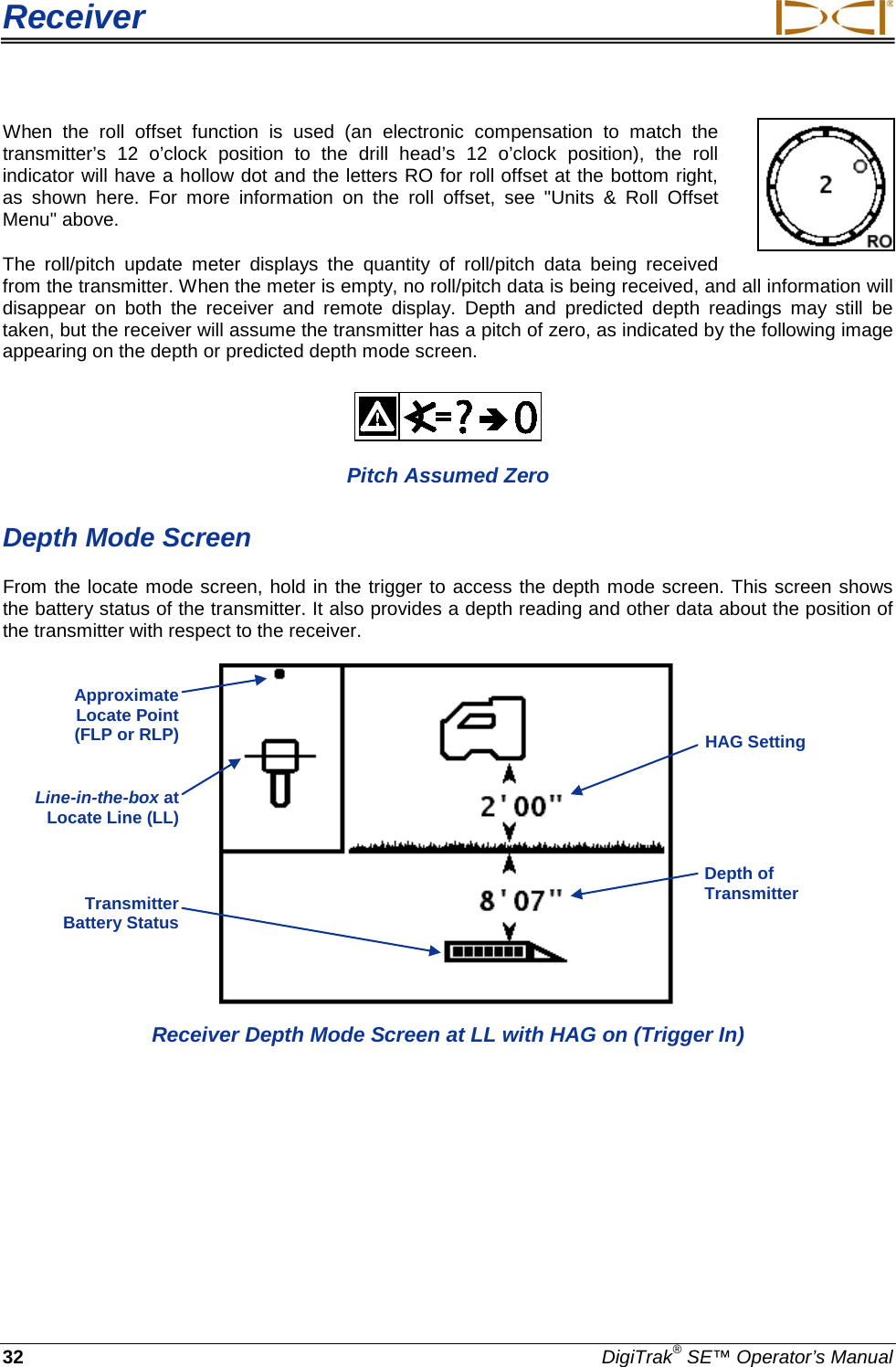
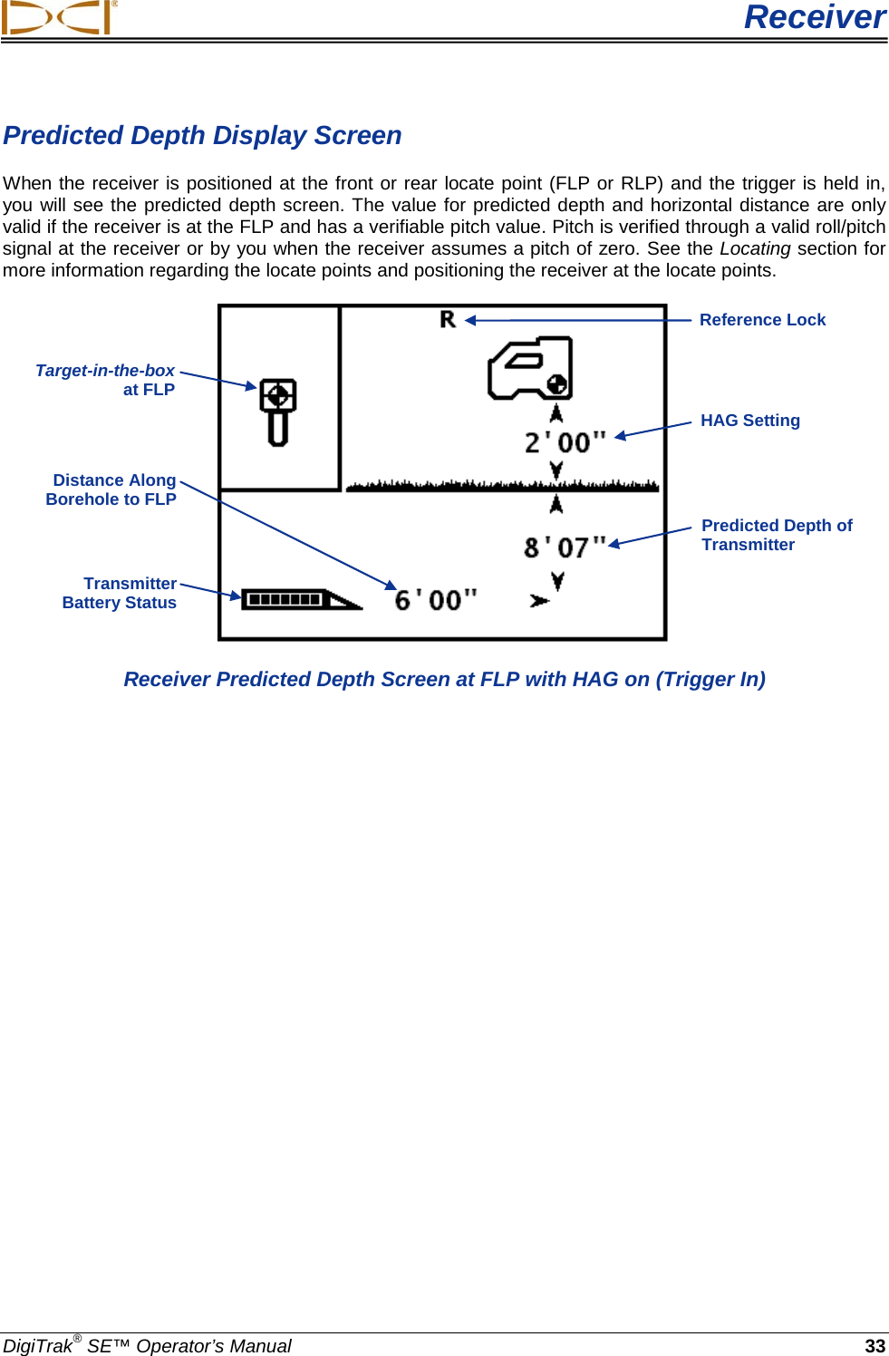
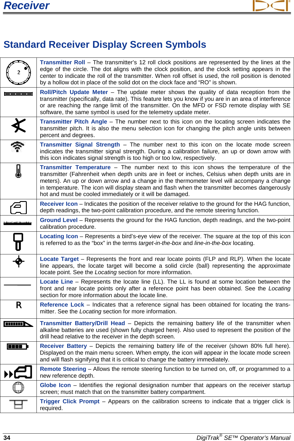
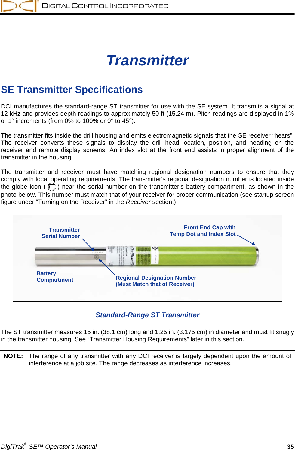
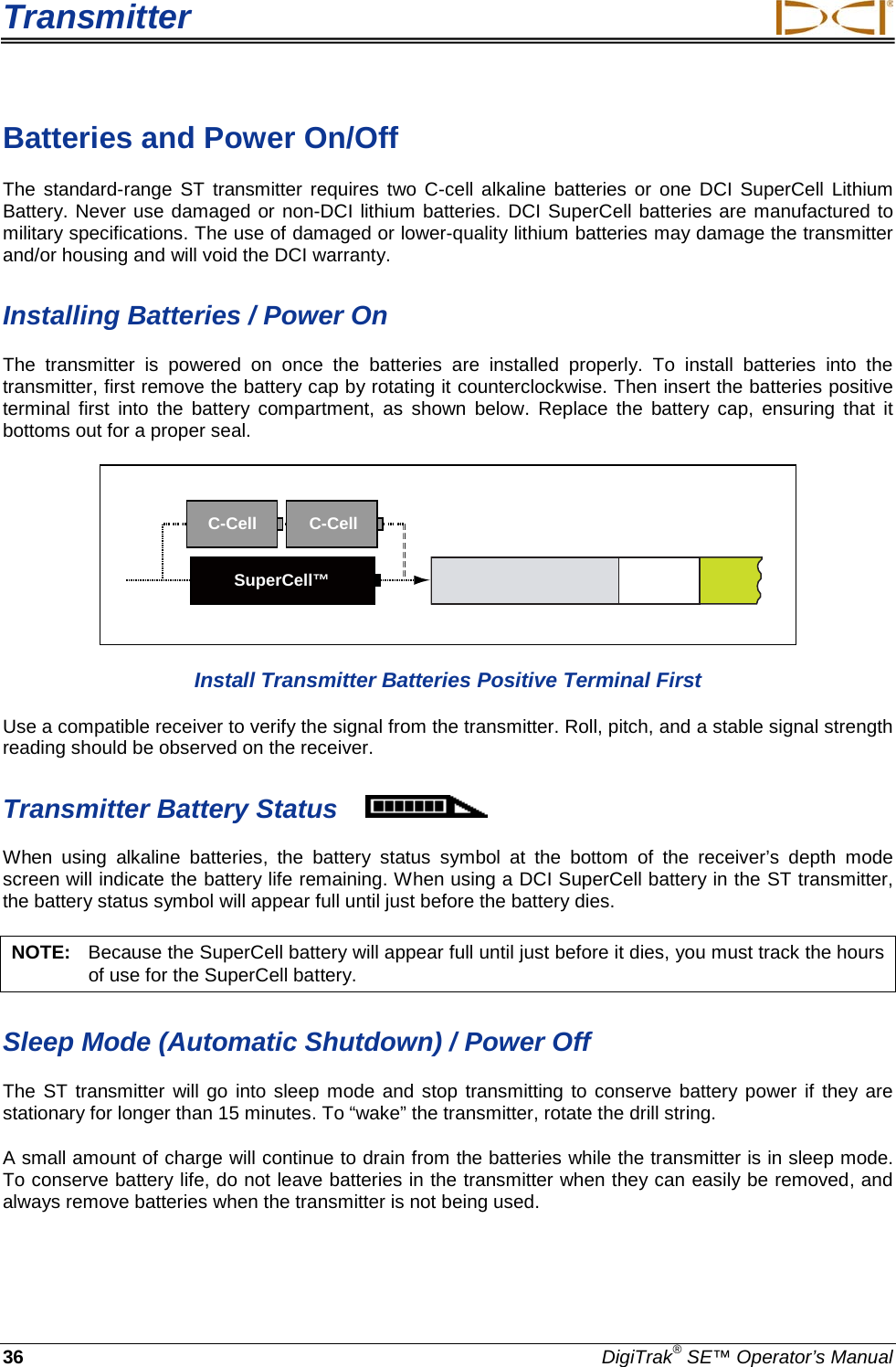
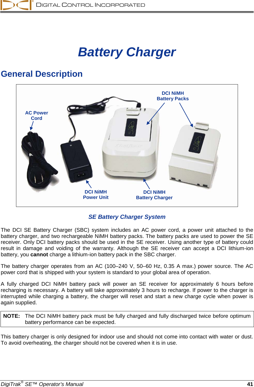
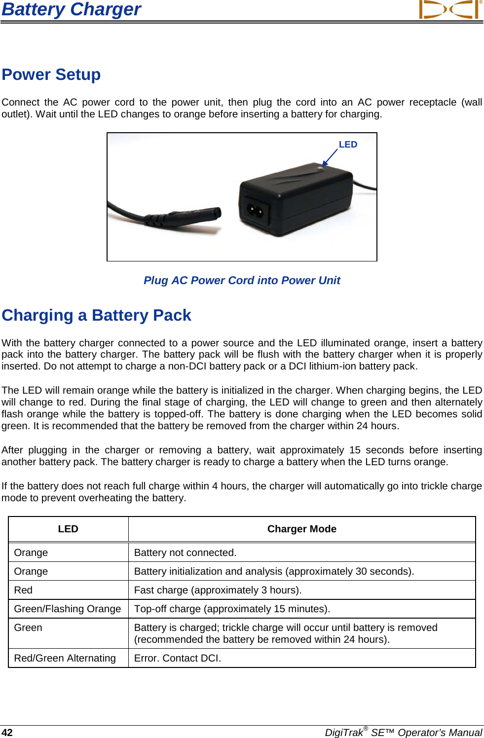
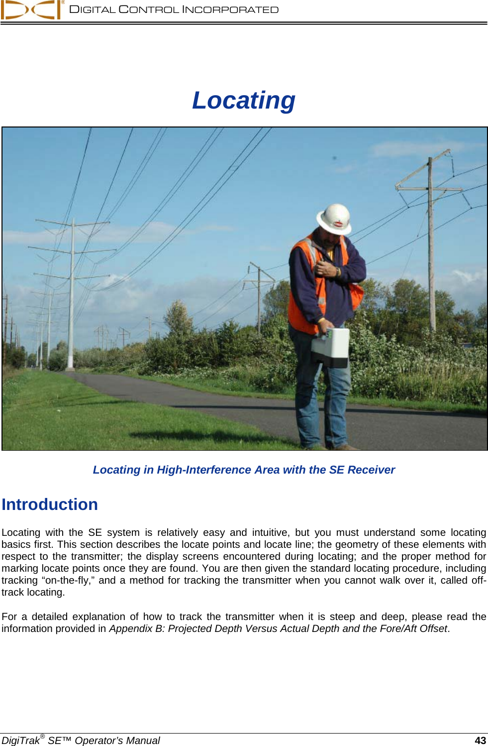
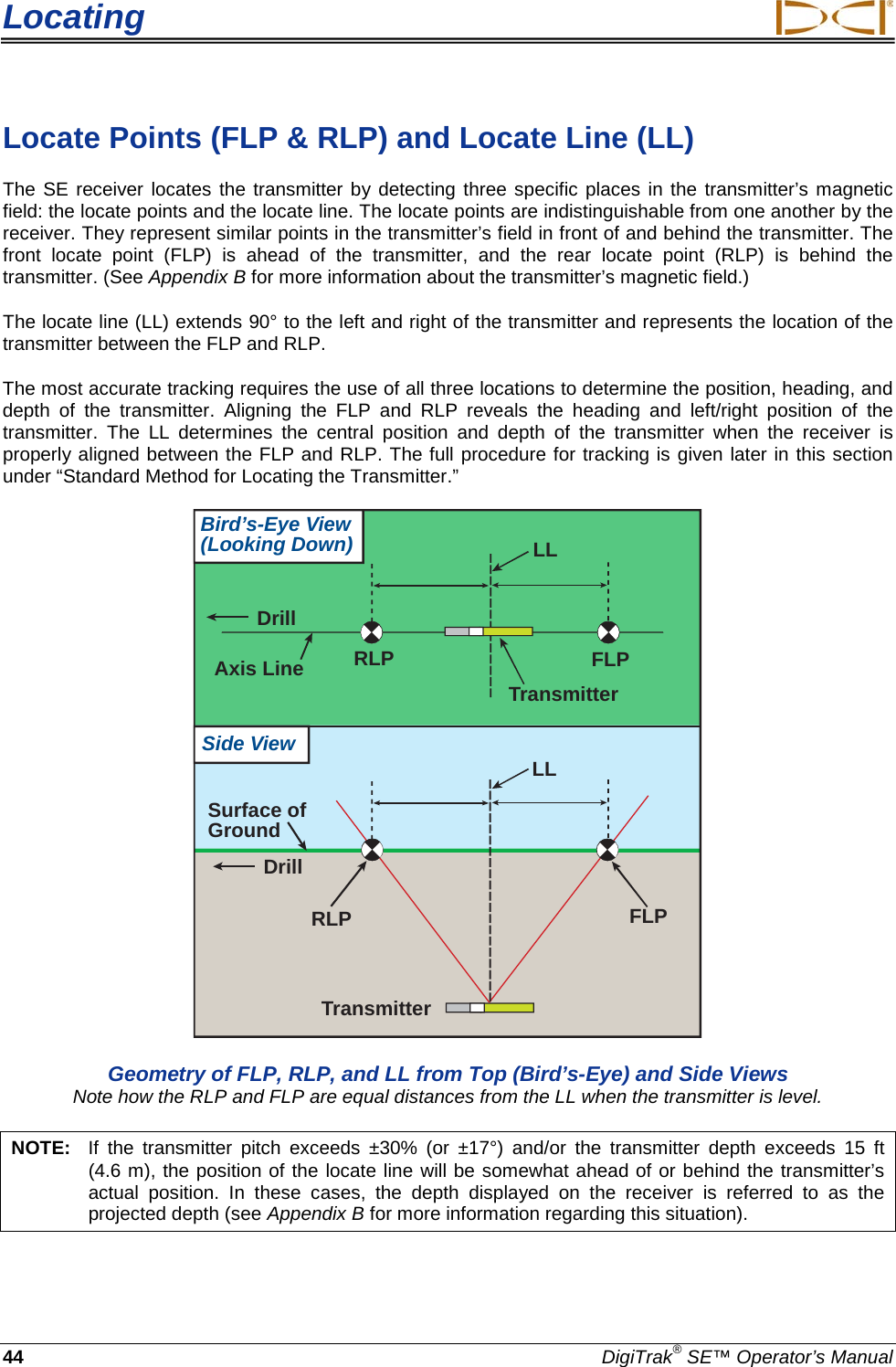
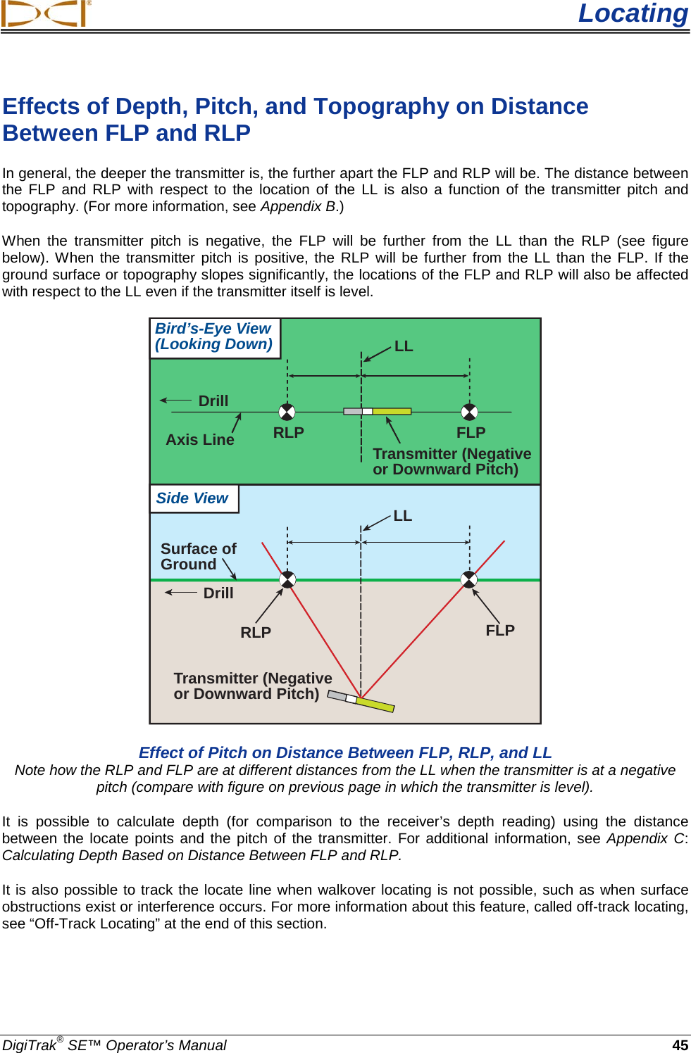
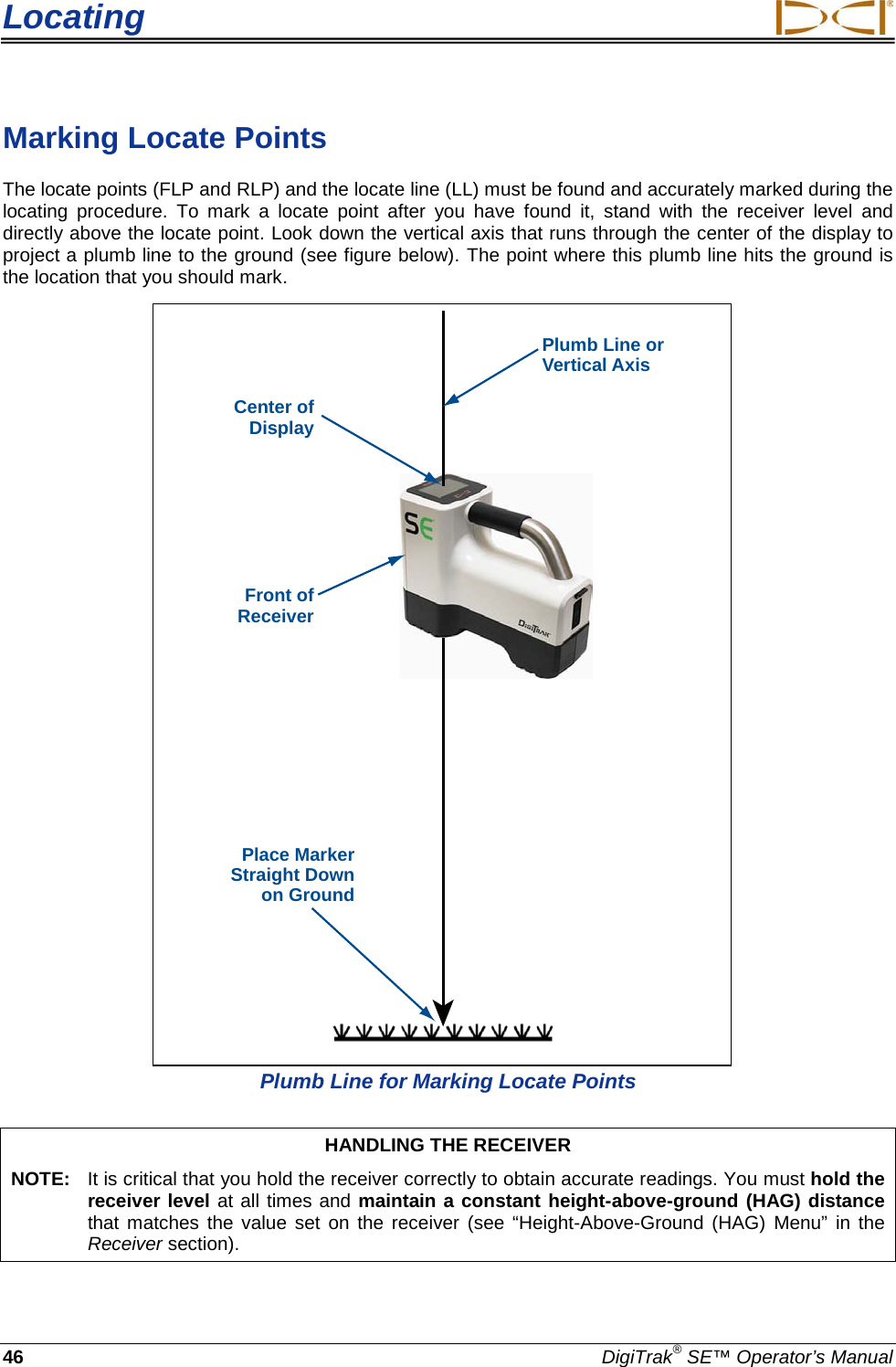
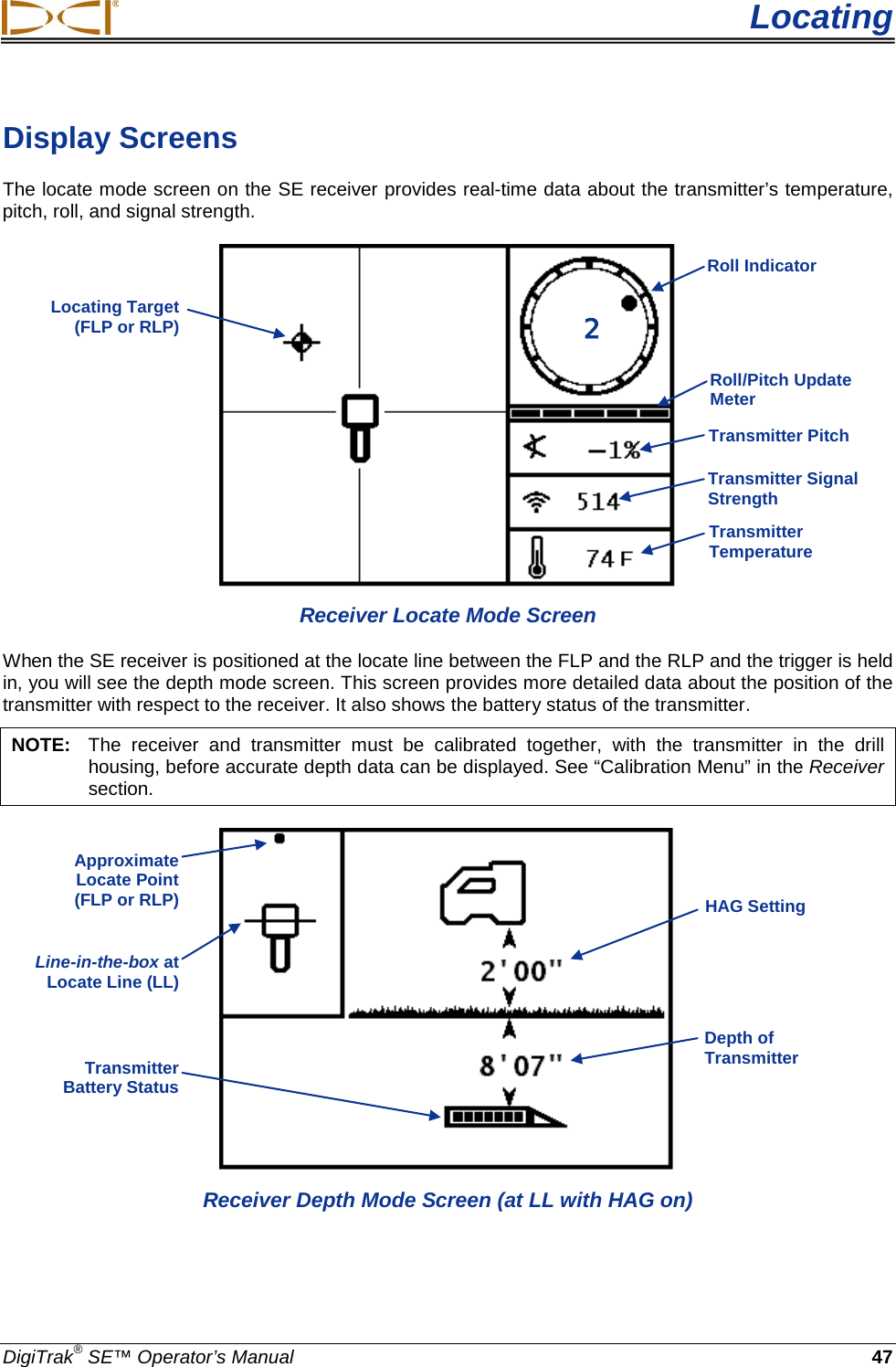
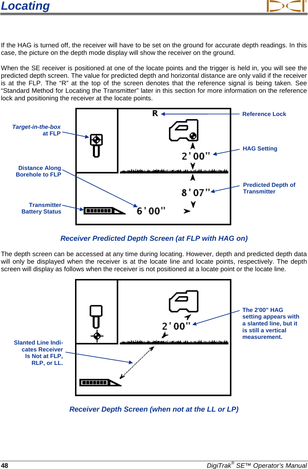
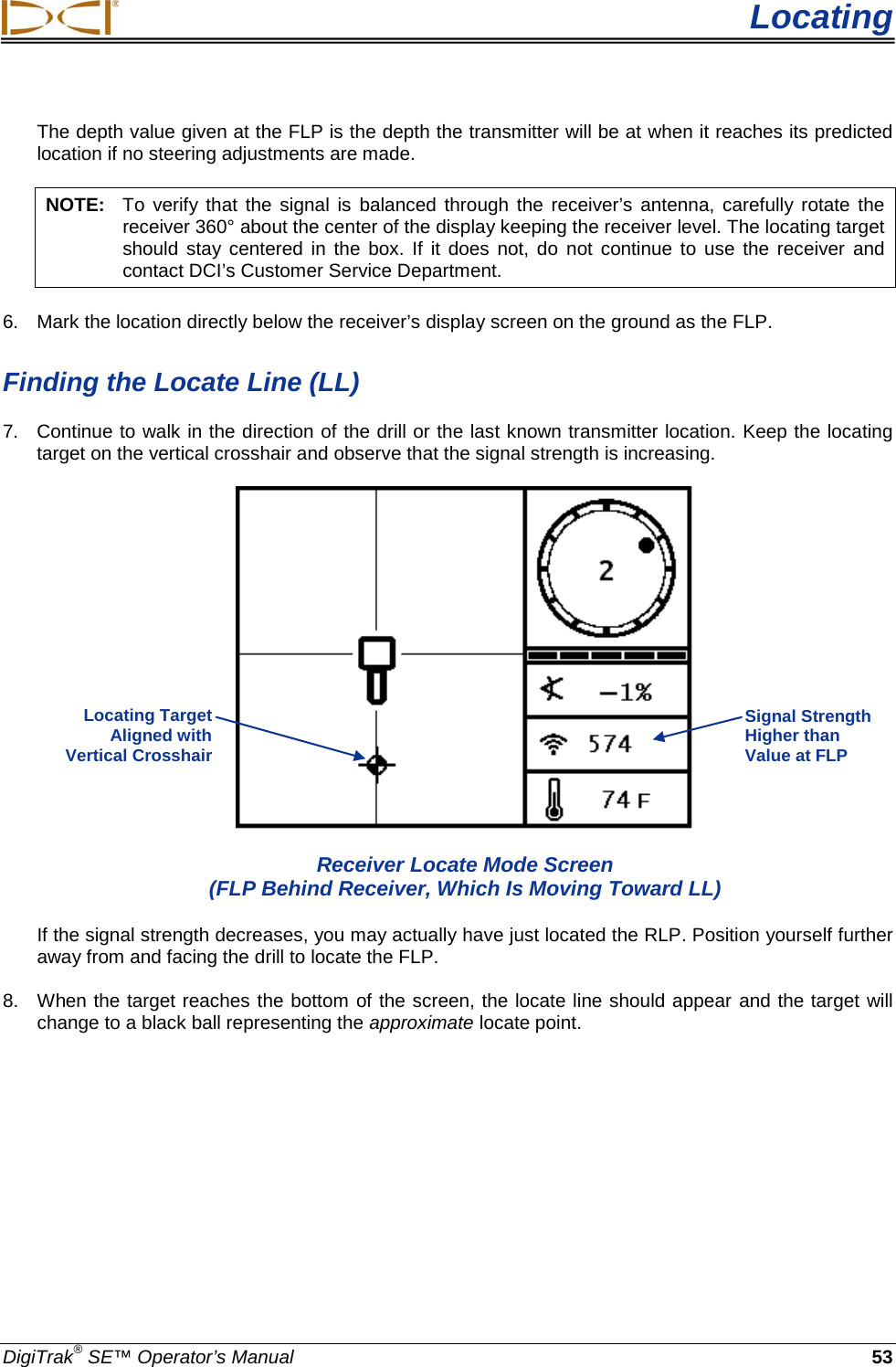
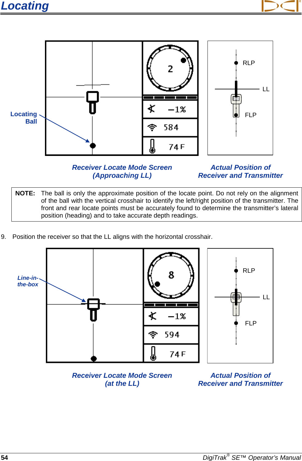
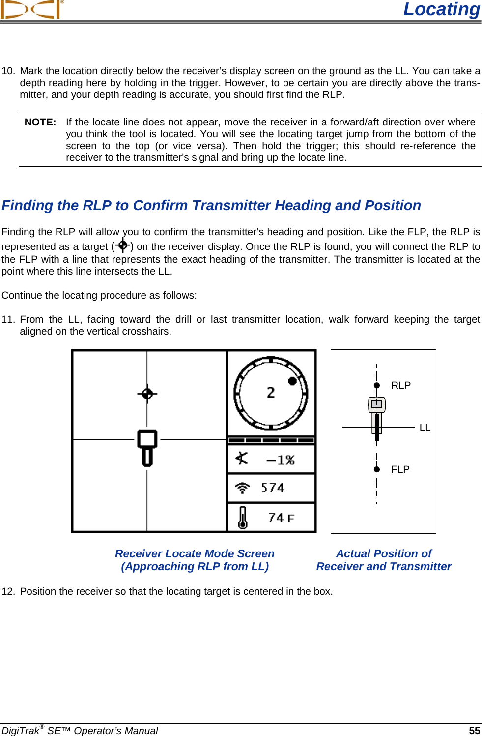
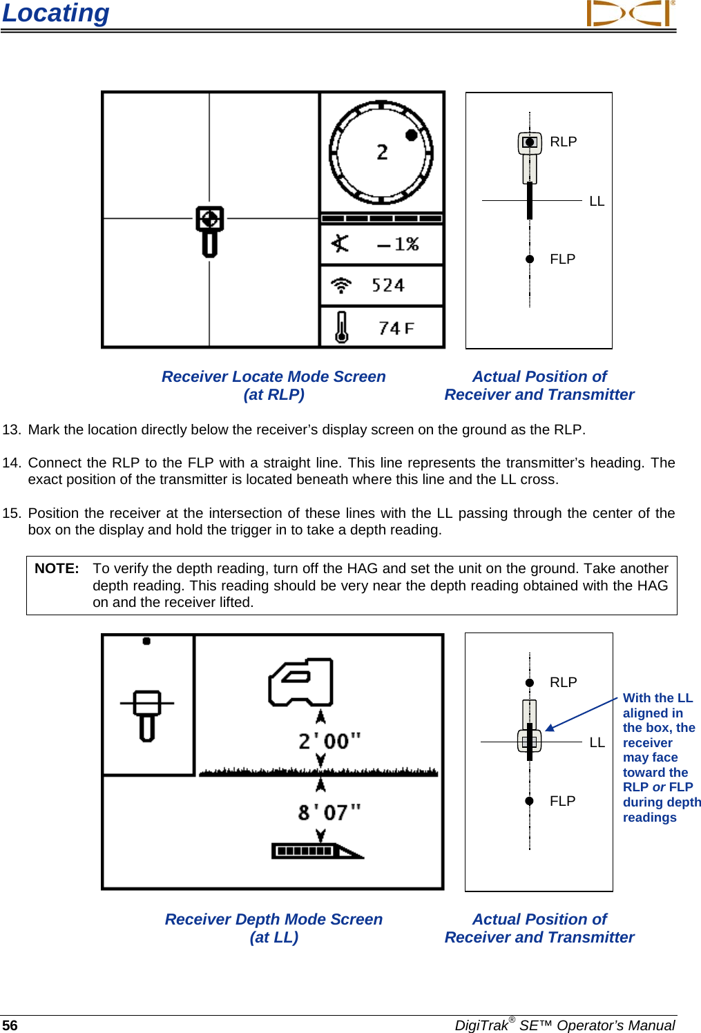
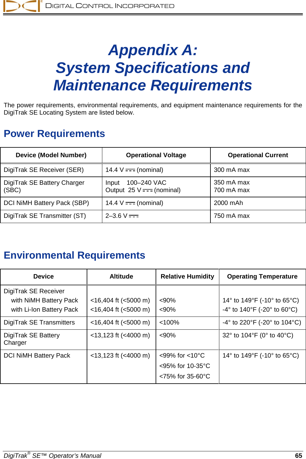
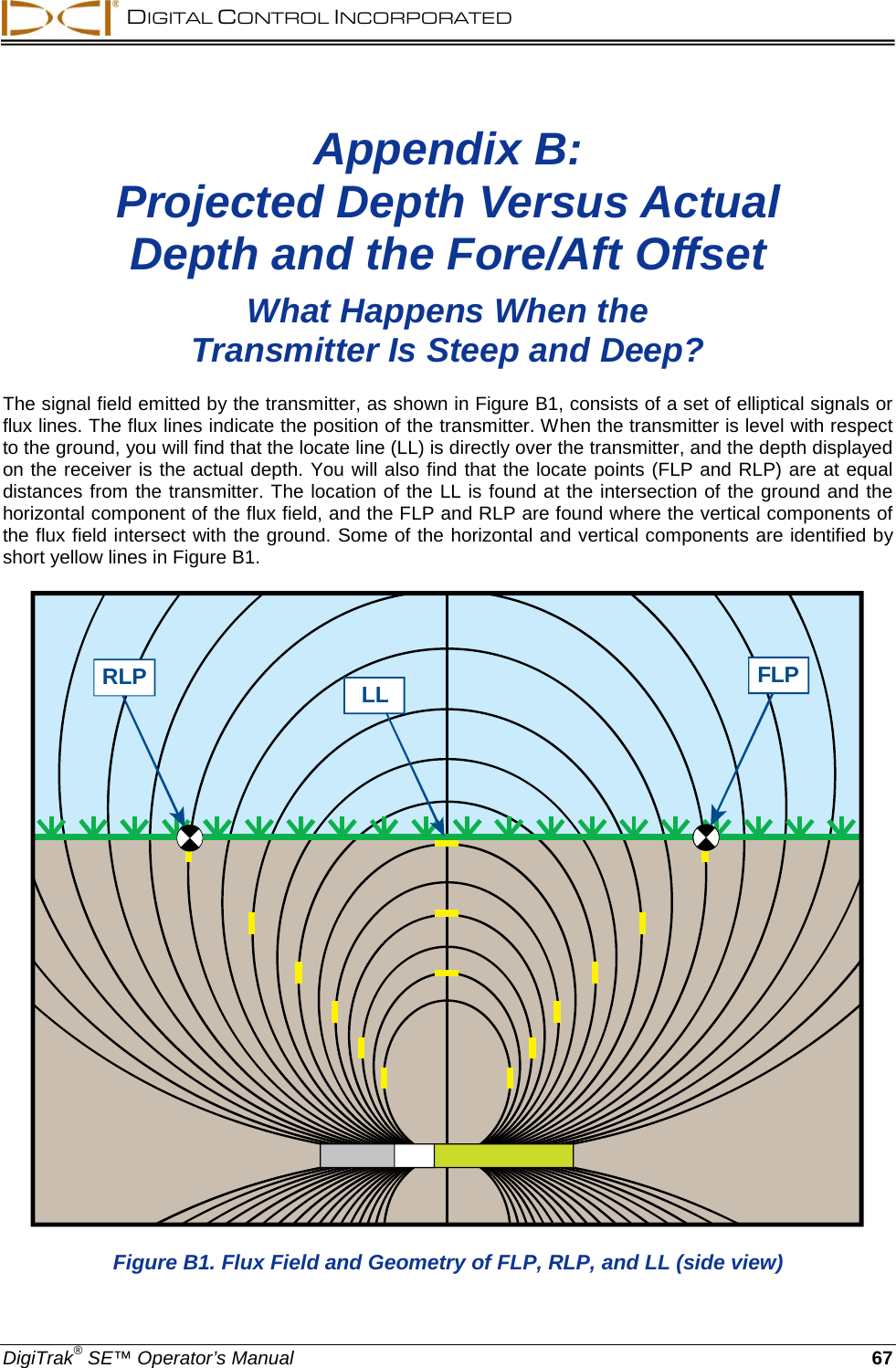
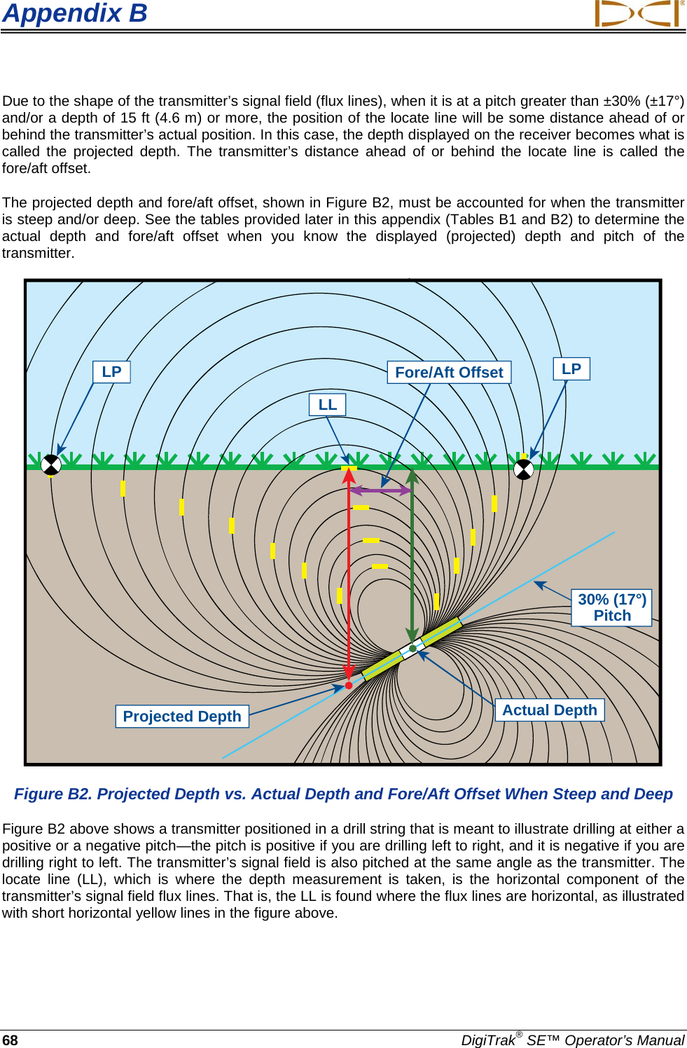
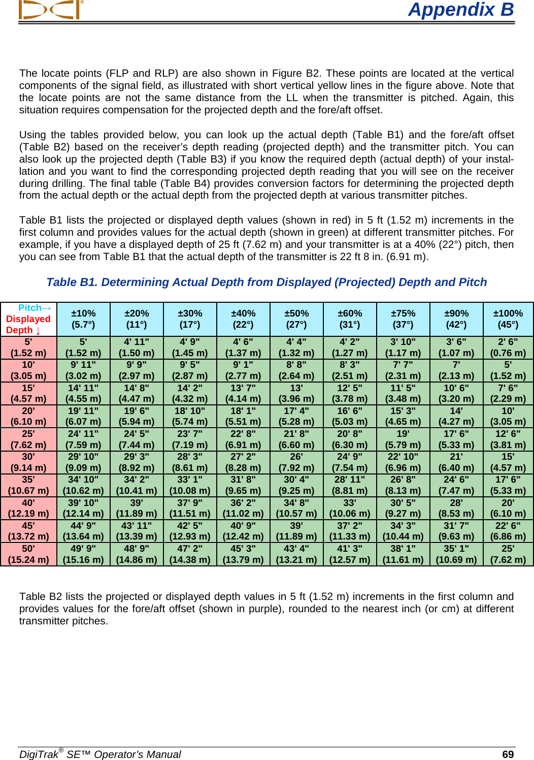
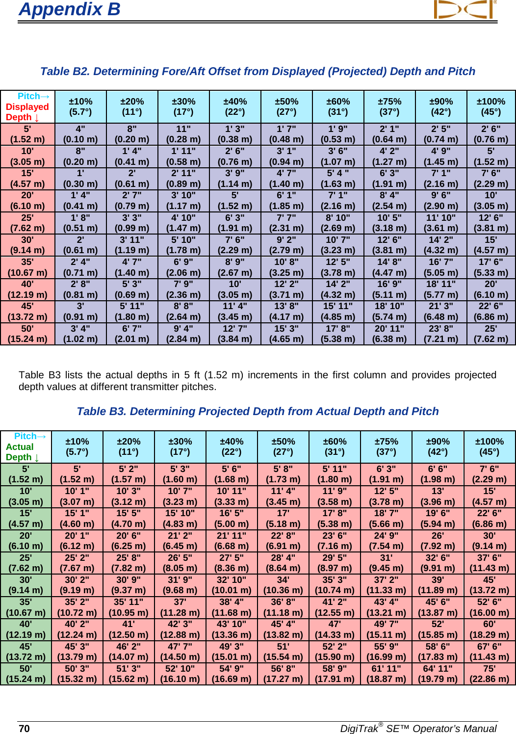
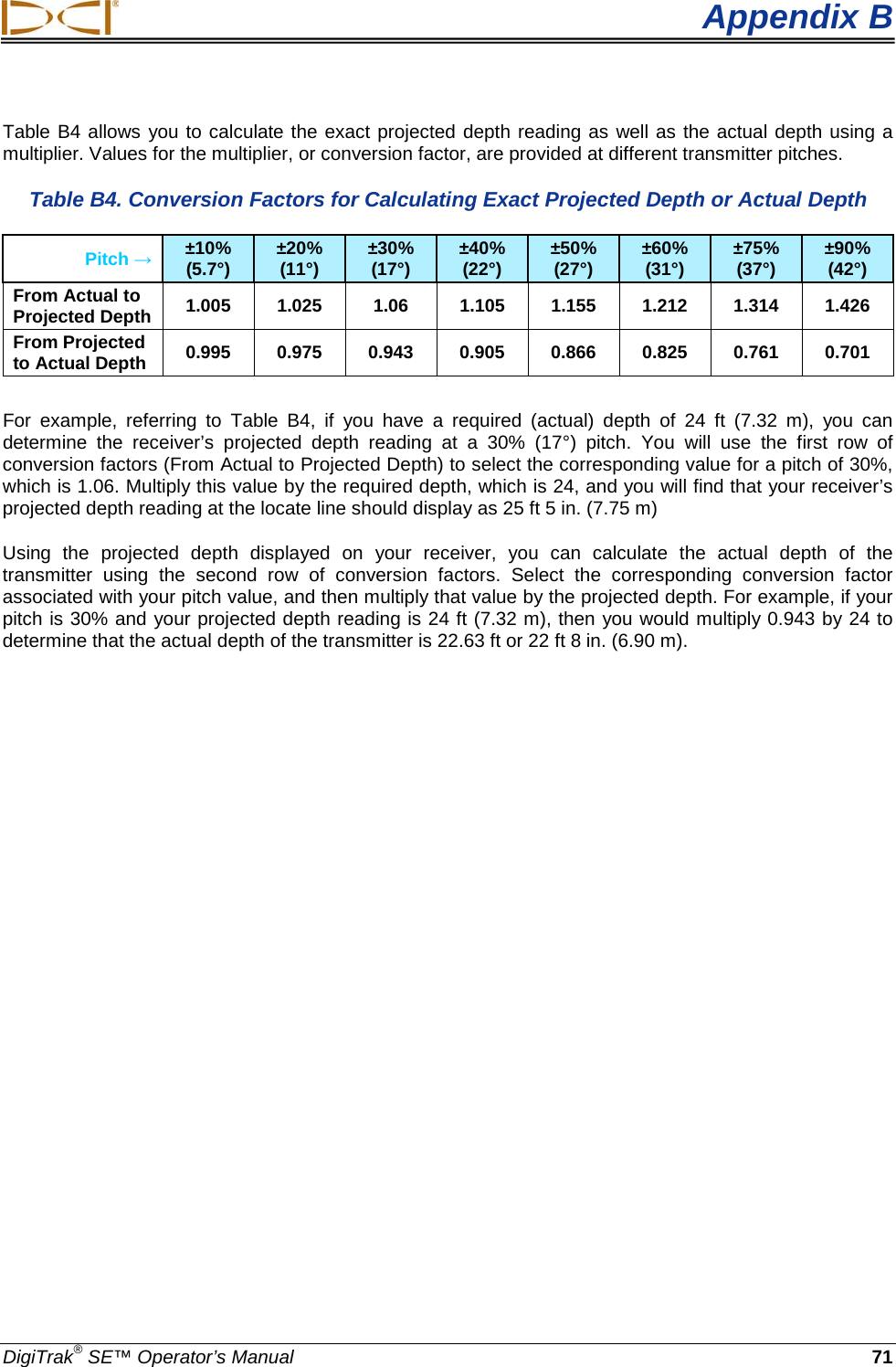
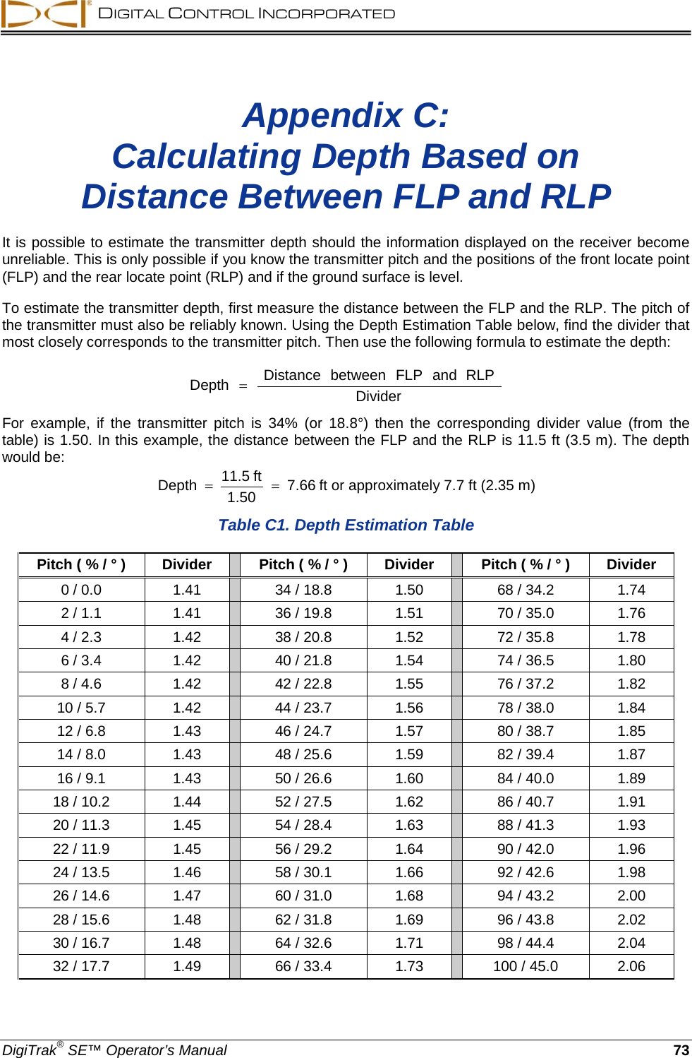
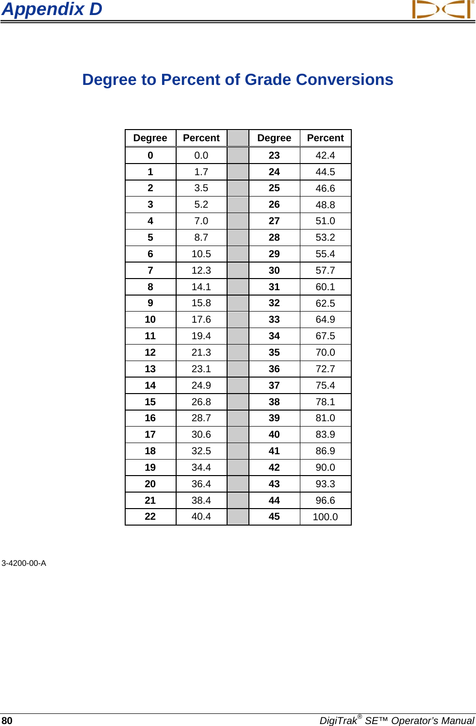
User Manual SE
User Manual SE
Navigation menu
Upload a User Manual
Namespaces
Wiki Guide
HTML
PDF
Info
Views
User Manual
Discussion / Help
Navigation