Digital Device DPD-4200AK 42 inch Plasma Display Monitor User Manual
Digital Device Inc. 42 inch Plasma Display Monitor
UserManual.wiki
>
Digital Device
>
DPD 4200AK User Manual
User Manual
Navigation menu
Upload a User Manual
Namespaces
Wiki Guide
HTML
PDF
Info
Views
User Manual
Discussion / Help
Navigation
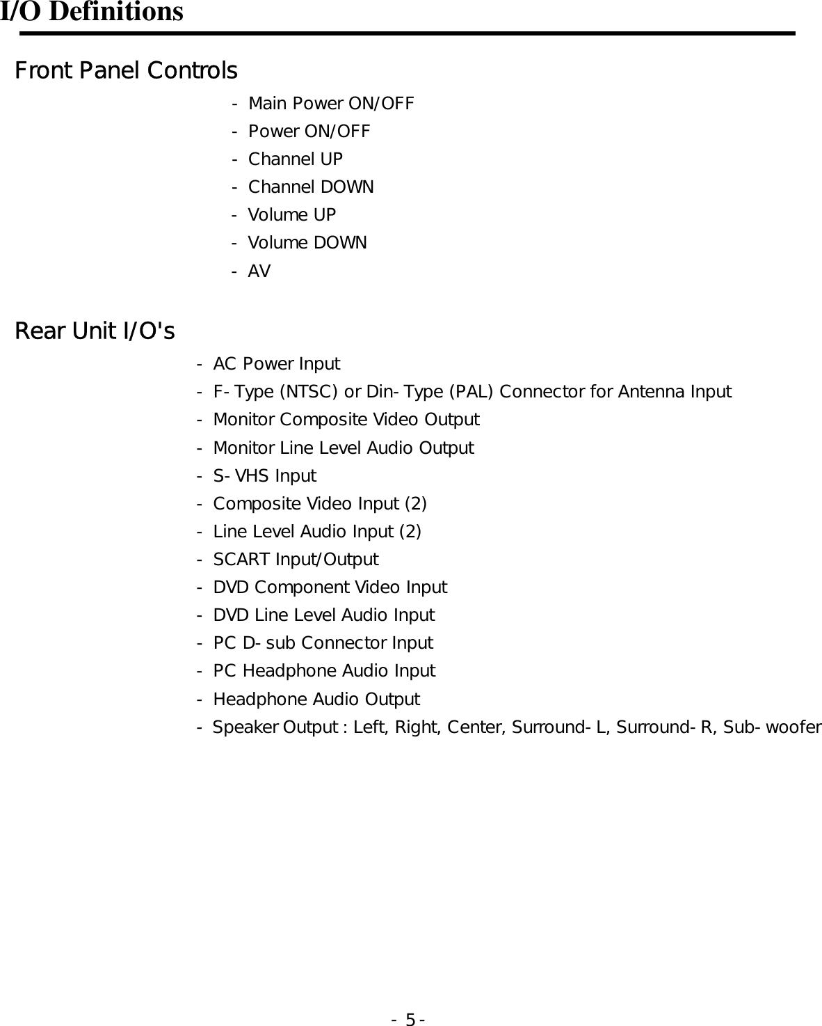
![Basic Operation 1. AV Input/Output Terminal 2. TV 1. Connect as the shown drawing. 2. Power on. 3. Press the [TV] button. 3. VIDEO 1. Connect as the shown drawing. 2. Power on. 3. Press the [VIDEO1] or [VIDEO2] button. - - 10](https://usermanual.wiki/Digital-Device/DPD-4200AK/User-Guide-390105-Page-10.png)
![Basic Operation 4. S-VHS 1. Connect as the shown drawing. 2. Power on. 3. Press the [VIDEO1] button. <Caution> Audio input must be connected with [Video1]. In the case when all input sources of S-VHS and Video1 Port are occupied, S-VHS input Sources displaypreceding to Video1 Port. 5. SCART Connection 1. Connect as the shown drawing. 2. Power on. 3. Press the [VIDEO2] button. <Caution> In the case when all input sources of SCART and Video2 Port are occupied, SCART input Sources displaypreceding to Video2 Port. - - 11](https://usermanual.wiki/Digital-Device/DPD-4200AK/User-Guide-390105-Page-11.png)
![Basic Operation 6. MONITOR OUT Connection <Caution> Monitor out is only applied to [TV], [VIDEO1], [VIDEO2]. 7. COMPONENT Video (ex. DVD, DTV Set-top Box) 1. Connect as the shown drawing. 2. Power on. 3. Press the [VIDEO3] button. - - 12](https://usermanual.wiki/Digital-Device/DPD-4200AK/User-Guide-390105-Page-12.png)
![Basic Operation 8. PC 1. Connect as the shown drawing. 2. Power on. 3. Press the [PC] button. 9. External Speaker & Headphone Connection 1. Power Off. 2. Connect as the shown drawing. 3. Power on. 4. Adjusting Audio setting. <Caution> Headphone outputs Sub-Signal Sounds. - - 13](https://usermanual.wiki/Digital-Device/DPD-4200AK/User-Guide-390105-Page-13.png)
![TV Channel Memory Auto Channel Memory Follow these steps for setting the Channel Memory automatically: c Press the [MENU] button. d Select [Channel] by the [ ]/[ ] buttons. e Select [Status] by pressing the [NEXT] button. f Select TV signal input mode by pressing the [ADJUST] button. g Select [Auto Channel] by pressing the [NEXT] button. h Select [ON] by pressing the [ADJUST] buttons. i Press the [MENU] button to stop the auto channel memory. ※ Highlighted choice will be in green. Auto Memory When Auto memory is on, it will scan CH 2~69 on the Air setting and CH 1~125 on the Cable setting. - - 14](https://usermanual.wiki/Digital-Device/DPD-4200AK/User-Guide-390105-Page-14.png)
![TV Channel Memory Manual Channel Memory Follow these steps to manually set the Channel Memory : c Select the channel by pressing the number button(s). d Press the [MENU] button. e Select [Channel] by the [ ]/[ ] buttons. f Select [Fine Tuning] mode by using the [NEXT] button. g Press the [ADJUST] button for the tuning adjustment. h Select [Memory] by using the [NEXT] button. i Select [Erase] or [Add] by pressing the [ADJUST] buttons. j Press the [MENU] button to exit the Channel Memory setting. ※ Highlighted choice will be in green. Fine Tuning The [ADJUST] button on the remote control will move the slide adjustment of the fine tuning bar positively or negatively. - - 15](https://usermanual.wiki/Digital-Device/DPD-4200AK/User-Guide-390105-Page-15.png)
![Picture Picture Adjustment Follow these steps to adjust the picture : c Press the [MENU] button. d Select the desired Mode by using the [ ]/[ ] buttons. e Move to the desired Mode by pressing the [NEXT] button. f Press the [ADJUST] button for adjusting the picture g Press the [MENU] button to exit the adjustment menu. ※ Highlighted choice will be in green. - - 16](https://usermanual.wiki/Digital-Device/DPD-4200AK/User-Guide-390105-Page-16.png)
![Picture Picture Size Adjustment Follow these steps to adjust the picture size : c Press the [MENU] button. d Select the Aspect Ratio by using the [ ]/[ ] buttons. e Move to the desired Mode by pressing the [NEXT] button. f Press the [ADJUST] button to adjust the picture size ratio. g Press the [MENU] button to exit Picture Size Adjustment. ※ Highlighted choice will be in green. [ZOOM + ] / [ZOOM - ] Button : Using the [ZOOM] button on the remote controller, you can expand the picture size 0 up to 500%. - - 17](https://usermanual.wiki/Digital-Device/DPD-4200AK/User-Guide-390105-Page-17.png)
![Picture Picture Adjustment in PC Mode Follow these steps to adjust the picture in PC Mode : c Press the [MENU] button. d Select the desired Mode by using the [ ]/[ ] buttons. e Move to the desired Mode by pressing the [NEXT] button. f Press the [ADJUST] button for adjusting the picture in PC Mode g Press the [MENU] button to exit the adjustment menu. ※ Highlighted choice will be in green. - - 18](https://usermanual.wiki/Digital-Device/DPD-4200AK/User-Guide-390105-Page-18.png)
![Picture Picture Size Adjustment in PC Mode Follow these steps for setting the Picture Size Adjustment of PC Mode. c Press the [MENU] button. d Select the Normal Scaling Modes by using the [ ]/[ ] uttons. e Move to the desired mode by pressing the [NEXT] button. f Press the [ADJUST] button to select the proper mode. g Press the [MENU] button to exit the adjustment menu. ※ Highlighted choice will be in green. [ZOOM + ] / [ZOOM - ] Button : Using the [ZOOM] button on the remote controller, you can expand the picture size 0 up to 500%. - - 19](https://usermanual.wiki/Digital-Device/DPD-4200AK/User-Guide-390105-Page-19.png)
![Audio Audio Mode Setting Follow these steps for setting Sound Mode : c Press the [MENU] button. d Select the Audio by using the [ ]/[ ] buttons. e Move to the desired Mode by pressing the [NEXT] button. f Press the [ADJUST] button to make the adjustment for Sound g Press the [MENU] button to exit the adjustment menu. ※ Highlighted choice will be in green. - - 20](https://usermanual.wiki/Digital-Device/DPD-4200AK/User-Guide-390105-Page-20.png)
![Audio Audio Adjustment Follow these steps to adjust the Sound : c Press the MENU button. d Select the Audio Adjust by using the [ ]/[ ] buttons. e Move to the desired Mode by pressing the [NEXT] button. f Press the [ADJUST] button to make the adjustment for Sound g Press the [MENU] button to exit the adjustment menu. ※ Highlighted choice will be in green. BASS : Changes the level of low frequency sound. TREBLE : Changes the level of high frequency sound BALANCE : Changes the balance of the left and right channels. Cen/Sur BALANCE : Changes the balance of the center and surround channels. - - 21](https://usermanual.wiki/Digital-Device/DPD-4200AK/User-Guide-390105-Page-21.png)
![Picture in Picture Picture in Picture Mode Setting Follow these steps below to set Picture in Picture mode : c Press the [MENU] button. d Select Picture in Picture by using the [ ]/[ ] button. e Select PIP size mode by pressing the [NEXT] button. f Move to desired mode by pressing the [ADJUST] button. g Select PIP Source Mode by pressing the [NEXT] button. h Select PIP Source by pressing the ADJUST button. i Press the [MENU] button to exit the adjustment menu. ※ Highlighted choice will be in green. - - 22](https://usermanual.wiki/Digital-Device/DPD-4200AK/User-Guide-390105-Page-22.png)
![Picture in Picture Watching Picture in Picture Press the [PIP ON/OFF] button. Watching PIP Press the [PIP AV] button. Changing the Sub Picture to AV Press the [▲ CH ▼] button. Changing the Sub Picture Channel Press the [POS] button. Changing the Sub Picture Position Press the [SWAP] button. PIP at PC Mode PC signal can be seen on the main picture but not on the sub picture. AT 800×600 mode, you can optimize PIP. Swapping Main for Sub picture - - 23](https://usermanual.wiki/Digital-Device/DPD-4200AK/User-Guide-390105-Page-23.png)
![Video Signal Format Video Signal Format Setting Follow these steps for setting the Video Signal Format. c Press the [MENU] button. d Select the Video Mode by using the [ ]/[ ] buttons. e Move to the desired system by pressing the [NEXT] button. f Press the [ADJUST] button to select the desired system. g Press the [MENU] button to exit the adjustment menu. ※ Highlighted choice will be in green. Auto : The video signals are automatically detected and the format is set accordingly. NTSC M : This is the standard format used mainly in the United States and Korea. PAL : This is the standard format used mainly in the United Kingdom and Germany. PAL-M : This is the standard format used mainly in Brazil. PAL-N : This is the standard format used mainly in Argentina. SECAM : This is the standard format used mainly in France and Russia. - - 24](https://usermanual.wiki/Digital-Device/DPD-4200AK/User-Guide-390105-Page-24.png)
![Color Temperature Color Temperature Setting Follow these steps for setting the Color Temperature. c Press the [MENU] button. d Select the Color Temperature by using the [ ]/[ ] buttons. e Move to the desired mode by pressing the [NEXT] button. f Press the [ADJUST] button to select the desired mode. g Press the [MENU] button to exit the adjustment menu. ※ Highlighted choice will be in green. Color Temperature : The higher temperature the coolest image looks like. The lower temperature the warmest image looks like. - - 25](https://usermanual.wiki/Digital-Device/DPD-4200AK/User-Guide-390105-Page-25.png)
![Specifications Power Source AC100V~240V, 50/60㎐ Power Consumption < 350W (Typical) Display Panel Screen Size 921 mm (H) × 518 mm (V) <42" diagonal> Number of Pixels 853(Horizontal) × 480 (Vertical) Brightness 550 cd/m2 Contrast Ratio 700:1 Displayable Colors 16,770,000 Colors Viewing Angle Over 160 degrees Display Mode Input Signal TV, Video, S-VHS, Component, PC RF Input System NTSC(F-Type) or PAL(DIN-Type) Video Input System NTSC, PAL, SECAM Input/Output Input PC (P), PC(S) Video1(V, L, R)/S-VHS Video2 (V, L, R)/SCART Video3 [Component (Y, Pb, Pr), Sound (L, R)] RF IN (NTSC F-TYPE, PAL DIN-TYPE) Output Monitor Out (V, L, R)/ SCART Speaker Out (L,R,Center,Surround L/R,Sub-W), Headphone Weight Without Stand 33 Kg Dimensions Without Stand 1080 mm (W) × 670mm (H) ×99.5 mm (D) Operation Condition Temperature 0° C ~ 40° C Humidity 20% ~ 80% Storage Temperature -25° C ~ 60° C - - 26](https://usermanual.wiki/Digital-Device/DPD-4200AK/User-Guide-390105-Page-26.png)