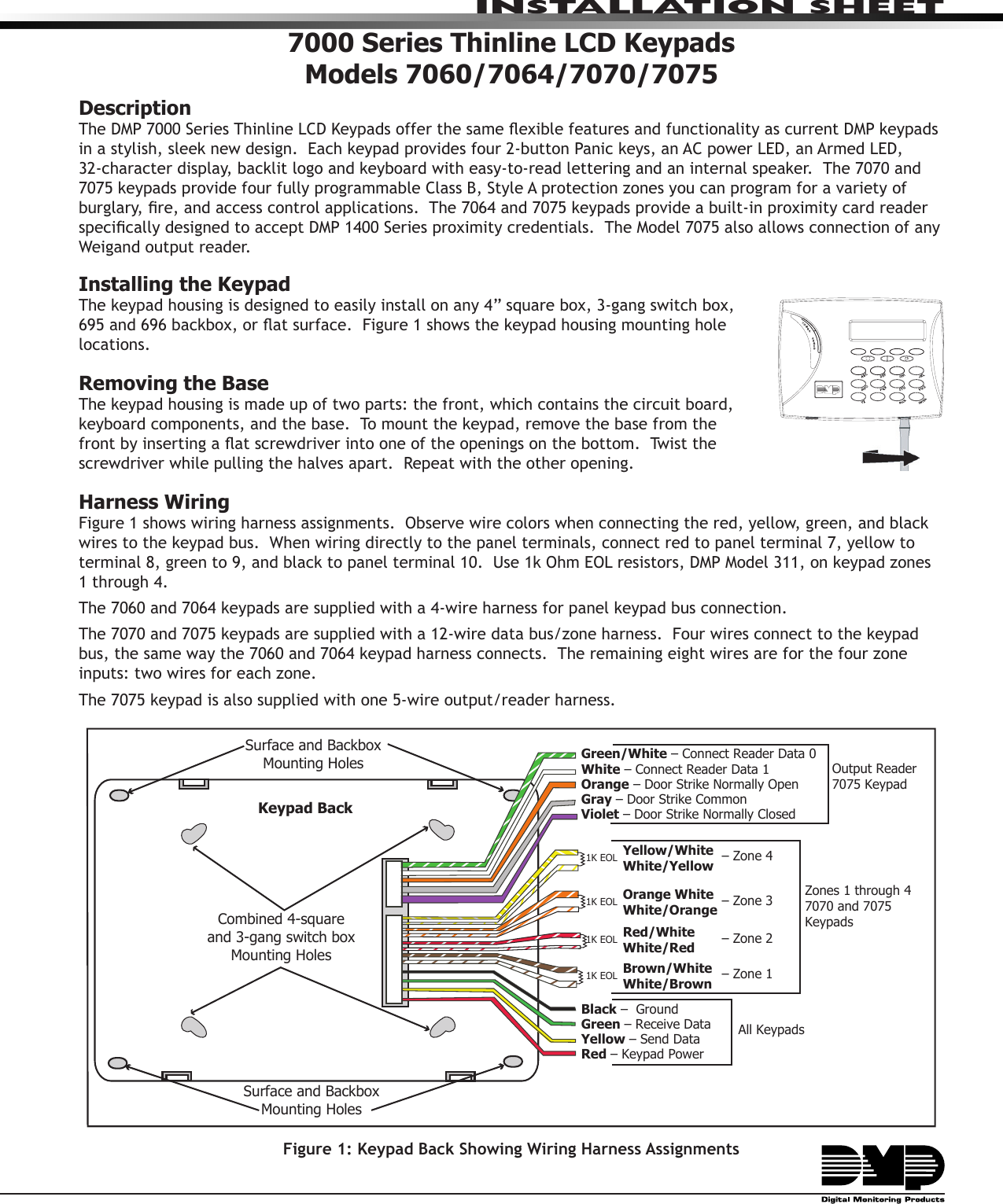
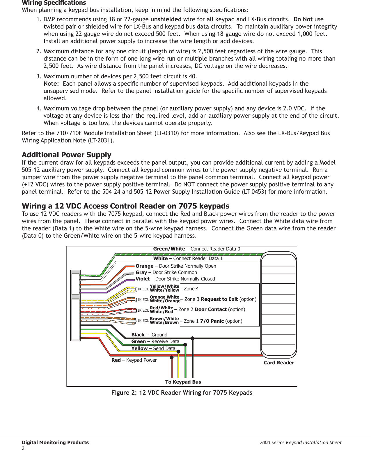
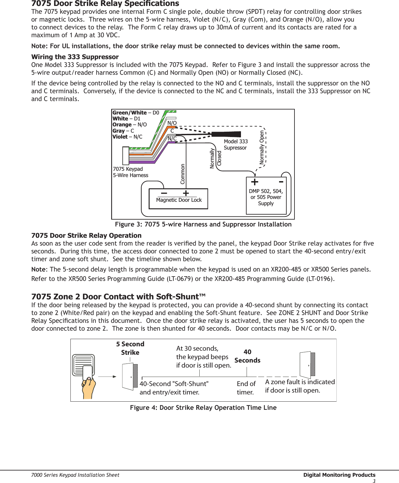
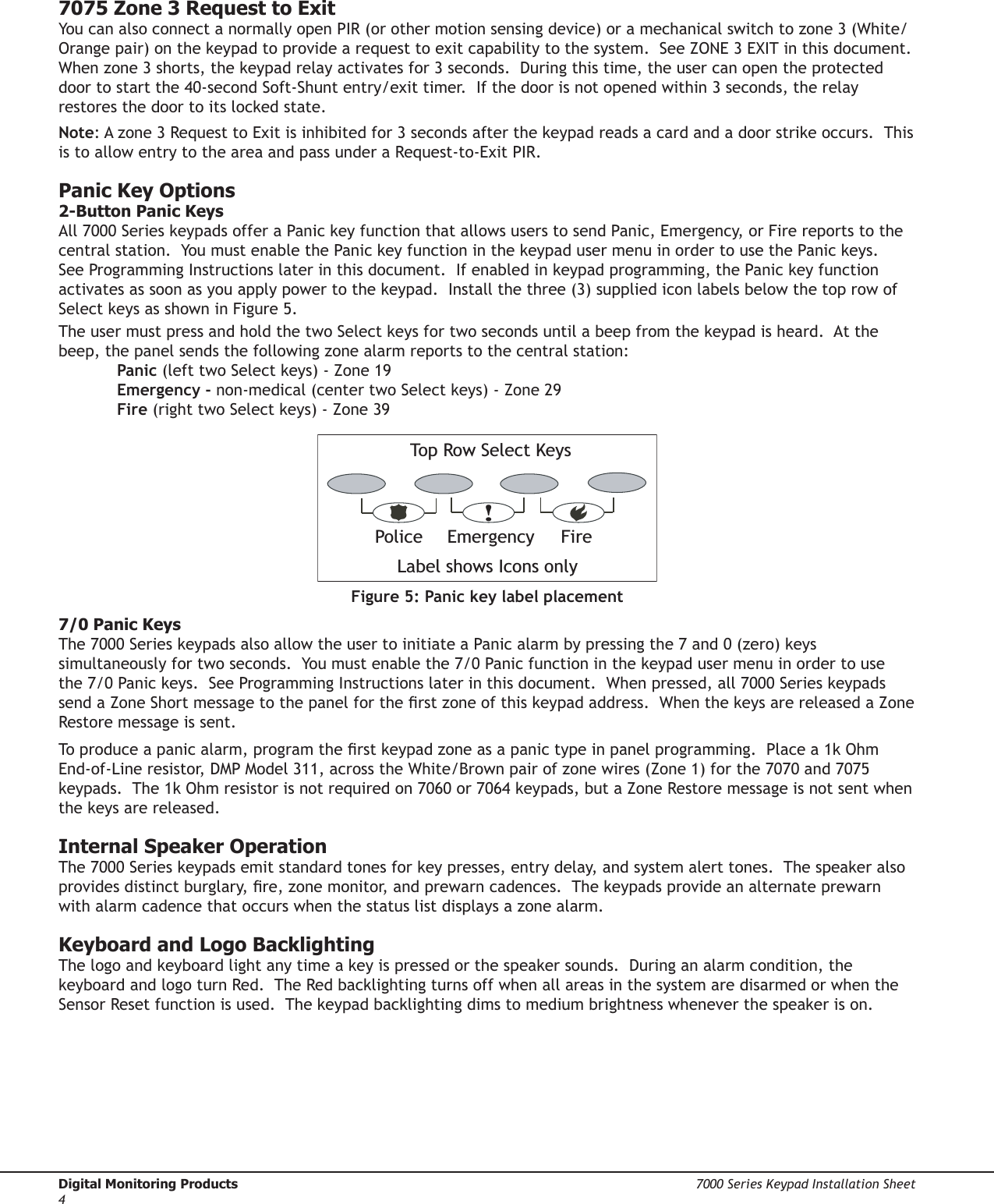
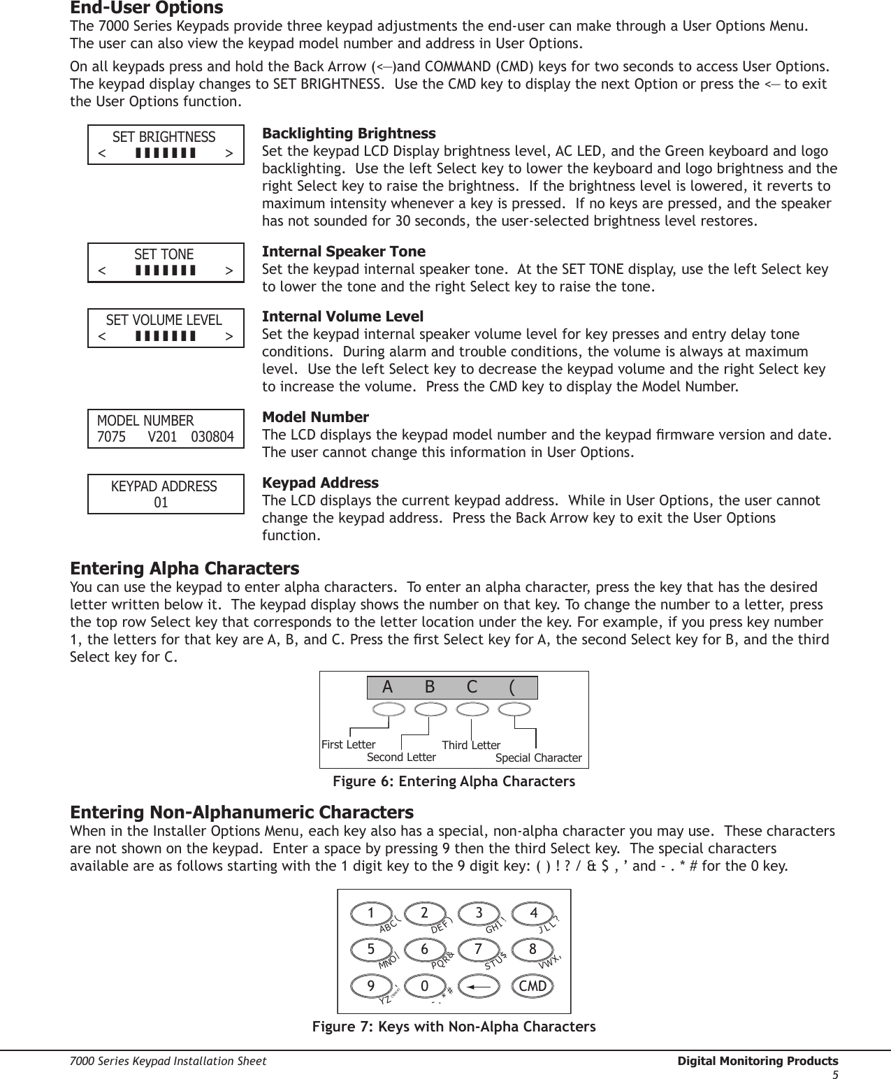
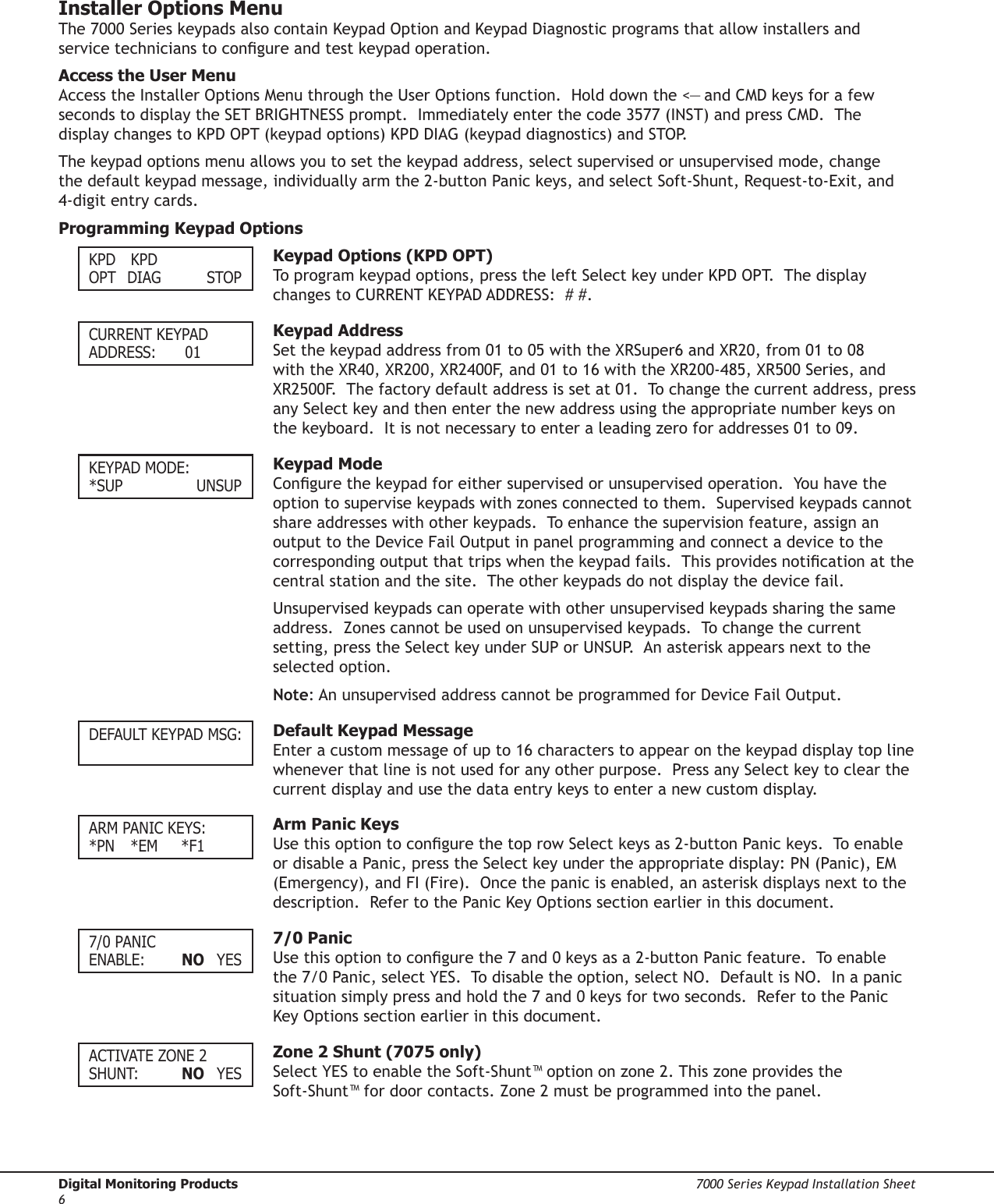
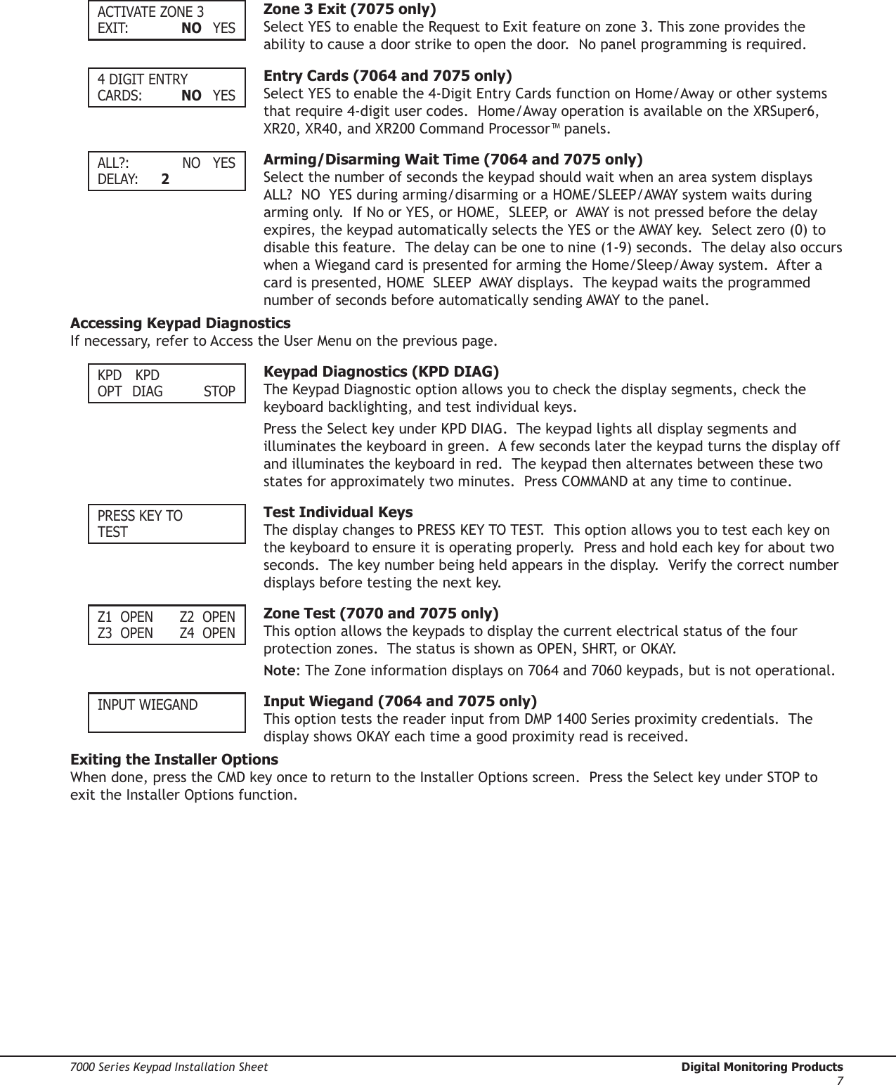
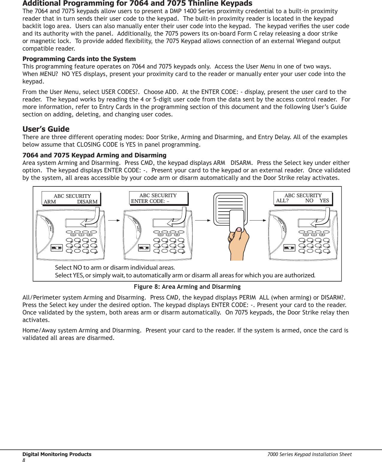
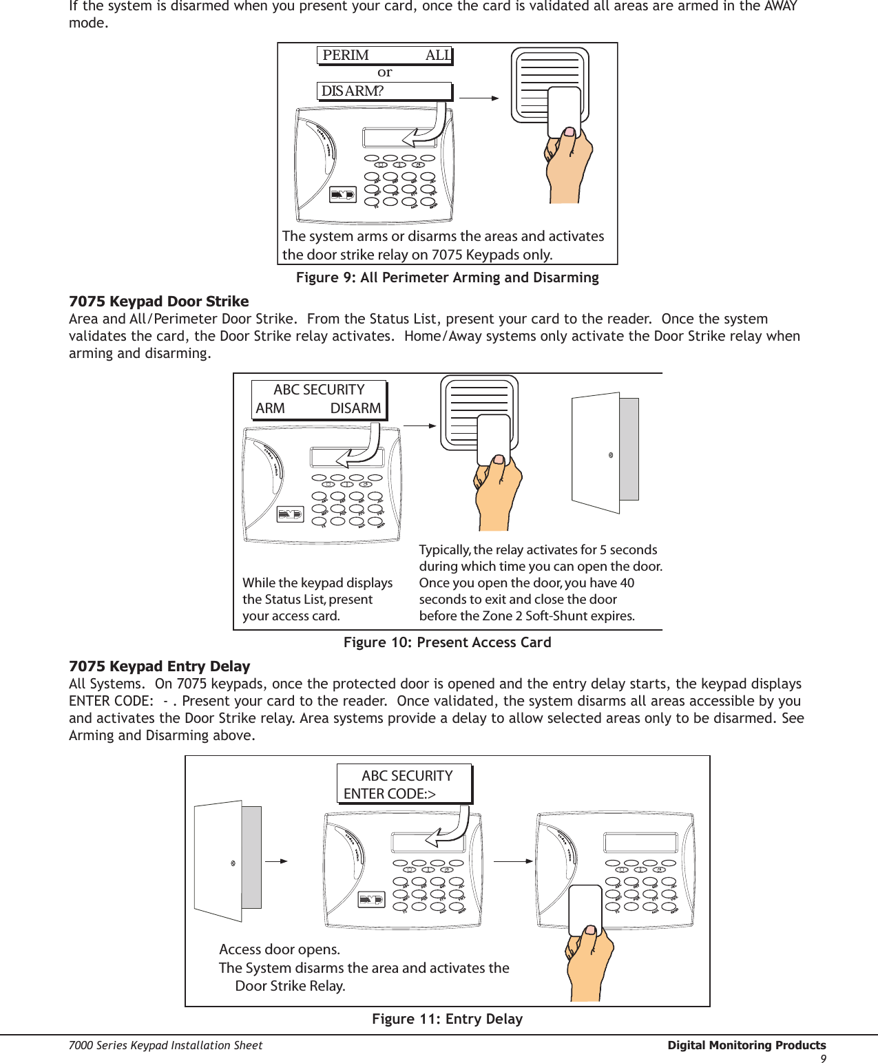
Digital Monitoring PC0086 RFID READER FOR ALARM SYSTEM KEYPAD User Manual LT 0778 7 04 indd

Digital Monitoring Products Inc RFID READER FOR ALARM SYSTEM KEYPAD LT 0778 7 04 indd

USERS MANUAL

INSTALLATION SHEET7000 Series Thinline LCD KeypadsModels 7060/7064/7070/7075DescriptionThe DMP 7000 Series Thinline LCD Keypads offer the same exible features and functionality as current DMP keypads in a stylish, sleek new design.  Each keypad provides four 2-button Panic keys, an AC power LED, an Armed LED, 32-character display, backlit logo and keyboard with easy-to-read lettering and an internal speaker.  The 7070 and 7075 keypads provide four fully programmable Class B, Style A protection zones you can program for a variety of burglary, re, and access control applications.  The 7064 and 7075 keypads provide a built-in proximity card reader specically designed to accept DMP 1400 Series proximity credentials.  The Model 7075 also allows connection of any Weigand output reader.Installing the KeypadThe keypad housing is designed to easily install on any 4” square box, 3-gang switch box, 695 and 696 backbox, or at surface.  Figure 1 shows the keypad housing mounting hole locations.Removing the BaseThe keypad housing is made up of two parts: the front, which contains the circuit board, keyboard components, and the base.  To mount the keypad, remove the base from the front by inserting a at screwdriver into one of the openings on the bottom.  Twist the screwdriver while pulling the halves apart.  Repeat with the other opening.Harness WiringFigure 1 shows wiring harness assignments.  Observe wire colors when connecting the red, yellow, green, and black wires to the keypad bus.  When wiring directly to the panel terminals, connect red to panel terminal 7, yellow to terminal 8, green to 9, and black to panel terminal 10.  Use 1k Ohm EOL resistors, DMP Model 311, on keypad zones 1 through 4. The 7060 and 7064 keypads are supplied with a 4-wire harness for panel keypad bus connection.  The 7070 and 7075 keypads are supplied with a 12-wire data bus/zone harness.  Four wires connect to the keypad bus, the same way the 7060 and 7064 keypad harness connects.  The remaining eight wires are for the four zone inputs: two wires for each zone.  The 7075 keypad is also supplied with one 5-wire output/reader harness.Surface and BackboxMounting HolesCombined 4-squareand 3-gang switch boxMounting HolesKeypad BackSurface and BackboxMounting Holes1K EOL1K EOL1K EOL1K EOLGreen/White – Connect Reader Data 0White – Connect Reader Data 1Orange – Door Strike Normally OpenGray – Door Strike CommonViolet – Door Strike Normally ClosedYellow/WhiteWhite/YellowOrange White White/OrangeRed/White White/RedBrown/White White/BrownBlack –  Ground Green – Receive DataYellow – Send Data Red – Keypad Power – Zone 4– Zone 3– Zone 2– Zone 1Output Reader7075 KeypadZones 1 through 47070 and 7075 KeypadsAll KeypadsFigure 1: Keypad Back Showing Wiring Harness Assignments
Digital Monitoring Products  7000 Series Keypad Installation Sheet27000 Series Keypad Installation Sheet  Digital Monitoring Products3Wiring SpecicationsWhen planning a keypad bus installation, keep in mind the following specications:1. DMP recommends using 18 or 22-gauge unshielded wire for all keypad and LX-Bus circuits.  Do Not use twisted pair or shielded wire for LX-Bus and keypad bus data circuits.  To maintain auxiliary power integrity when using 22-gauge wire do not exceed 500 feet.  When using 18-gauge wire do not exceed 1,000 feet.  Install an additional power supply to increase the wire length or add devices. 2. Maximum distance for any one circuit (length of wire) is 2,500 feet regardless of the wire gauge.  This distance can be in the form of one long wire run or multiple branches with all wiring totaling no more than 2,500 feet.  As wire distance from the panel increases, DC voltage on the wire decreases.3. Maximum number of devices per 2,500 feet circuit is 40.  Note:  Each panel allows a specic number of supervised keypads.  Add additional keypads in the unsupervised mode.  Refer to the panel installation guide for the specic number of supervised keypads allowed.  4. Maximum voltage drop between the panel (or auxiliary power supply) and any device is 2.0 VDC.  If the voltage at any device is less than the required level, add an auxiliary power supply at the end of the circuit.  When voltage is too low, the devices cannot operate properly.  Refer to the 710/710F Module Installation Sheet (LT-0310) for more information.  Also see the LX-Bus/Keypad Bus Wiring Application Note (LT-2031).    Additional Power SupplyIf the current draw for all keypads exceeds the panel output, you can provide additional current by adding a Model 505-12 auxiliary power supply.  Connect all keypad common wires to the power supply negative terminal.  Run a jumper wire from the power supply negative terminal to the panel common terminal.  Connect all keypad power (+12 VDC) wires to the power supply positive terminal.  Do NOT connect the power supply positive terminal to any panel terminal.  Refer to the 504-24 and 505-12 Power Supply Installation Guide (LT-0453) for more information. Wiring a 12 VDC Access Control Reader on 7075 keypadsTo use 12 VDC readers with the 7075 keypad, connect the Red and Black power wires from the reader to the power wires from the panel.  These connect in parallel with the keypad power wires.  Connect the White data wire from the reader (Data 1) to the White wire on the 5-wire keypad harness.  Connect the Green data wire from the reader (Data 0) to the Green/White wire on the 5-wire keypad harness. 1K EOL1K EOL1K EOL1K EOLGreen/White – Connect Reader Data 0White – Connect Reader Data 1Orange – Door Strike Normally OpenGray – Door Strike CommonViolet – Door Strike Normally ClosedYellow/WhiteWhite/YellowOrange White White/OrangeRed/White White/RedBrown/White White/BrownBlack –  GroundGreen – Receive DataYellow – Send Data Red – Keypad Power– Zone 4– Zone 3 Request to Exit (option)– Zone 2 Door Contact (option)– Zone 1 7/0 Panic (option)To Keypad BusCard ReaderFigure 2: 12 VDC Reader Wiring for 7075 Keypads
Digital Monitoring Products  7000 Series Keypad Installation Sheet27000 Series Keypad Installation Sheet  Digital Monitoring Products37075 Door Strike Relay SpecicationsThe 7075 keypad provides one internal Form C single pole, double throw (SPDT) relay for controlling door strikes or magnetic locks.  Three wires on the 5-wire harness, Violet (N/C), Gray (Com), and Orange (N/O), allow you to connect devices to the relay.  The Form C relay draws up to 30mA of current and its contacts are rated for a maximum of 1 Amp at 30 VDC.Note: For UL installations, the door strike relay must be connected to devices within the same room.Wiring the 333 Suppressor One Model 333 Suppressor is included with the 7075 Keypad.  Refer to Figure 3 and install the suppressor across the 5-wire output/reader harness Common (C) and Normally Open (NO) or Normally Closed (NC).   If the device being controlled by the relay is connected to the NO and C terminals, install the suppressor on the NO and C terminals.  Conversely, if the device is connected to the NC and C terminals, install the 333 Suppressor on NC and C terminals. Figure 3: 7075 5-wire Harness and Suppressor Installation7075 Door Strike Relay OperationAs soon as the user code sent from the reader is veried by the panel, the keypad Door Strike relay activates for ve seconds.  During this time, the access door connected to zone 2 must be opened to start the 40-second entry/exit timer and zone soft shunt.  See the timeline shown below.Note: The 5-second delay length is programmable when the keypad is used on an XR200-485 or XR500 Series panels.  Refer to the XR500 Series Programming Guide (LT-0679) or the XR200-485 Programming Guide (LT-0196).7075 Zone 2 Door Contact with Soft-Shunt™If the door being released by the keypad is protected, you can provide a 40-second shunt by connecting its contact to zone 2 (White/Red pair) on the keypad and enabling the Soft-Shunt feature.  See ZONE 2 SHUNT and Door Strike Relay Specications in this document.  Once the door strike relay is activated, the user has 5 seconds to open the door connected to zone 2.  The zone is then shunted for 40 seconds.  Door contacts may be N/C or N/O. 5 SecondStrike40-Second "Soft-Shunt"and entry/exit timer.At 30 seconds,the keypad beepsif door is still open.End of timer.40SecondsA zone fault is indicatedif door is still open.Figure 4: Door Strike Relay Operation Time Line
Digital Monitoring Products  7000 Series Keypad Installation Sheet47000 Series Keypad Installation Sheet  Digital Monitoring Products57075 Zone 3 Request to ExitYou can also connect a normally open PIR (or other motion sensing device) or a mechanical switch to zone 3 (White/Orange pair) on the keypad to provide a request to exit capability to the system.  See ZONE 3 EXIT in this document.  When zone 3 shorts, the keypad relay activates for 3 seconds.  During this time, the user can open the protected door to start the 40-second Soft-Shunt entry/exit timer.  If the door is not opened within 3 seconds, the relay restores the door to its locked state.Note: A zone 3 Request to Exit is inhibited for 3 seconds after the keypad reads a card and a door strike occurs.  This is to allow entry to the area and pass under a Request-to-Exit PIR. Panic Key Options2-Button Panic KeysAll 7000 Series keypads offer a Panic key function that allows users to send Panic, Emergency, or Fire reports to the central station.  You must enable the Panic key function in the keypad user menu in order to use the Panic keys.  See Programming Instructions later in this document.  If enabled in keypad programming, the Panic key function activates as soon as you apply power to the keypad.  Install the three (3) supplied icon labels below the top row of Select keys as shown in Figure 5.   The user must press and hold the two Select keys for two seconds until a beep from the keypad is heard.  At the beep, the panel sends the following zone alarm reports to the central station:  Panic (left two Select keys) - Zone 19 Emergency - non-medical (center two Select keys) - Zone 29 Fire (right two Select keys) - Zone 39   !Figure 5: Panic key label placement7/0 Panic KeysThe 7000 Series keypads also allow the user to initiate a Panic alarm by pressing the 7 and 0 (zero) keys simultaneously for two seconds.  You must enable the 7/0 Panic function in the keypad user menu in order to use the 7/0 Panic keys.  See Programming Instructions later in this document.  When pressed, all 7000 Series keypads send a Zone Short message to the panel for the rst zone of this keypad address.  When the keys are released a Zone Restore message is sent.To produce a panic alarm, program the rst keypad zone as a panic type in panel programming.  Place a 1k Ohm End-of-Line resistor, DMP Model 311, across the White/Brown pair of zone wires (Zone 1) for the 7070 and 7075 keypads.  The 1k Ohm resistor is not required on 7060 or 7064 keypads, but a Zone Restore message is not sent when the keys are released.Internal Speaker OperationThe 7000 Series keypads emit standard tones for key presses, entry delay, and system alert tones.  The speaker also provides distinct burglary, re, zone monitor, and prewarn cadences.  The keypads provide an alternate prewarn with alarm cadence that occurs when the status list displays a zone alarm. Keyboard and Logo BacklightingThe logo and keyboard light any time a key is pressed or the speaker sounds.  During an alarm condition, the keyboard and logo turn Red.  The Red backlighting turns off when all areas in the system are disarmed or when the Sensor Reset function is used.  The keypad backlighting dims to medium brightness whenever the speaker is on.
Digital Monitoring Products  7000 Series Keypad Installation Sheet47000 Series Keypad Installation Sheet  Digital Monitoring Products5End-User OptionsThe 7000 Series Keypads provide three keypad adjustments the end-user can make through a User Options Menu.  The user can also view the keypad model number and address in User Options.  On all keypads press and hold the Back Arrow (<—)and COMMAND (CMD) keys for two seconds to access User Options.  The keypad display changes to SET BRIGHTNESS.  Use the CMD key to display the next Option or press the <— to exit the User Options function.   SET BRIGHTNESS<          >  Backlighting BrightnessSet the keypad LCD Display brightness level, AC LED, and the Green keyboard and logo backlighting.  Use the left Select key to lower the keyboard and logo brightness and the right Select key to raise the brightness.  If the brightness level is lowered, it reverts to maximum intensity whenever a key is pressed.  If no keys are pressed, and the speaker has not sounded for 30 seconds, the user-selected brightness level restores.  SET TONE<          >  Internal Speaker ToneSet the keypad internal speaker tone.  At the SET TONE display, use the left Select key to lower the tone and the right Select key to raise the tone.    SET VOLUME LEVEL<          >  Internal Volume LevelSet the keypad internal speaker volume level for key presses and entry delay tone conditions.  During alarm and trouble conditions, the volume is always at maximum level.  Use the left Select key to decrease the keypad volume and the right Select key to increase the volume.  Press the CMD key to display the Model Number.  MODEL NUMBER7075  V201  030804  Model NumberThe LCD displays the keypad model number and the keypad rmware version and date.  The user cannot change this information in User Options.    KEYPAD ADDRESS  01  Keypad AddressThe LCD displays the current keypad address.  While in User Options, the user cannot change the keypad address.  Press the Back Arrow key to exit the User Options function. Entering Alpha CharactersYou can use the keypad to enter alpha characters.  To enter an alpha character, press the key that has the desired letter written below it.  The keypad display shows the number on that key. To change the number to a letter, press the top row Select key that corresponds to the letter location under the key. For example, if you press key number 1, the letters for that key are A, B, and C. Press the rst Select key for A, the second Select key for B, and the third Select key for C. First LetterSecond LetterThird LetterSpecial Character(CBAFigure 6: Entering Alpha CharactersEntering Non-Alphanumeric CharactersWhen in the Installer Options Menu, each key also has a special, non-alpha character you may use.  These characters are not shown on the keypad.  Enter a space by pressing 9 then the third Select key.  The special characters available are as follows starting with the 1 digit key to the 9 digit key: ( ) ! ? / & $ ‚ ’ and - . * # for the 0 key. 1  2  3  49  0    CMD5  6  7  8A(CBD)FEG!IHJ?LLV,XWS$UTP&RQM/ONY'(space)Z-#*.Figure 7: Keys with Non-Alpha Characters
Digital Monitoring Products  7000 Series Keypad Installation Sheet67000 Series Keypad Installation Sheet  Digital Monitoring Products7Installer Options MenuThe 7000 Series keypads also contain Keypad Option and Keypad Diagnostic programs that allow installers and service technicians to congure and test keypad operation.Access the User MenuAccess the Installer Options Menu through the User Options function.  Hold down the <— and CMD keys for a few seconds to display the SET BRIGHTNESS prompt.  Immediately enter the code 3577 (INST) and press CMD.  The display changes to KPD OPT (keypad options) KPD DIAG (keypad diagnostics) and STOP.The keypad options menu allows you to set the keypad address, select supervised or unsupervised mode, change the default keypad message, individually arm the 2-button Panic keys, and select Soft-Shunt, Request-to-Exit, and 4-digit entry cards. Programming Keypad OptionsKPD  KPDOPT  DIAG    STOP  Keypad Options (KPD OPT) To program keypad options, press the left Select key under KPD OPT.  The display changes to CURRENT KEYPAD ADDRESS:  # #. CURRENT KEYPADADDRESS:    01  Keypad AddressSet the keypad address from 01 to 05 with the XRSuper6 and XR20, from 01 to 08 with the XR40, XR200, XR2400F, and 01 to 16 with the XR200-485, XR500 Series, and XR2500F.  The factory default address is set at 01.  To change the current address, press any Select key and then enter the new address using the appropriate number keys on the keyboard.  It is not necessary to enter a leading zero for addresses 01 to 09.KEYPAD MODE:*SUP     UNSUP  Keypad ModeCongure the keypad for either supervised or unsupervised operation.  You have the option to supervise keypads with zones connected to them.  Supervised keypads cannot share addresses with other keypads.  To enhance the supervision feature, assign an output to the Device Fail Output in panel programming and connect a device to the corresponding output that trips when the keypad fails.  This provides notication at the central station and the site.  The other keypads do not display the device fail. Unsupervised keypads can operate with other unsupervised keypads sharing the same address.  Zones cannot be used on unsupervised keypads.  To change the current setting, press the Select key under SUP or UNSUP.  An asterisk appears next to the selected option.Note: An unsupervised address cannot be programmed for Device Fail Output. DEFAULT KEYPAD MSG:  Default Keypad MessageEnter a custom message of up to 16 characters to appear on the keypad display top line whenever that line is not used for any other purpose.  Press any Select key to clear the current display and use the data entry keys to enter a new custom display. ARM PANIC KEYS:*PN  *EM  *F1  Arm Panic KeysUse this option to congure the top row Select keys as 2-button Panic keys.  To enable or disable a Panic, press the Select key under the appropriate display: PN (Panic), EM (Emergency), and FI (Fire).  Once the panic is enabled, an asterisk displays next to the description.  Refer to the Panic Key Options section earlier in this document.7/0 PANIC ENABLE:    NO  YES  7/0 PanicUse this option to congure the 7 and 0 keys as a 2-button Panic feature.  To enable the 7/0 Panic, select YES.  To disable the option, select NO.  Default is NO.  In a panic situation simply press and hold the 7 and 0 keys for two seconds.  Refer to the Panic Key Options section earlier in this document.ACTIVATE ZONE 2SHUNT:    NO  YES  Zone 2 Shunt (7075 only)Select YES to enable the Soft-Shunt™ option on zone 2. This zone provides the Soft-Shunt™ for door contacts. Zone 2 must be programmed into the panel.
Digital Monitoring Products  7000 Series Keypad Installation Sheet67000 Series Keypad Installation Sheet  Digital Monitoring Products7ACTIVATE ZONE 3EXIT:    NO  YES  Zone 3 Exit (7075 only)Select YES to enable the Request to Exit feature on zone 3. This zone provides the ability to cause a door strike to open the door.  No panel programming is required.  4 DIGIT ENTRYCARDS:    NO  YES  Entry Cards (7064 and 7075 only)Select YES to enable the 4-Digit Entry Cards function on Home/Away or other systems that require 4-digit user codes.  Home/Away operation is available on the XRSuper6, XR20, XR40, and XR200 Command Processor™ panels.  ALL?:     NO  YESDELAY:  2  Arming/Disarming Wait Time (7064 and 7075 only)Select the number of seconds the keypad should wait when an area system displays  ALL?  NO  YES during arming/disarming or a HOME/SLEEP/AWAY system waits during arming only.  If No or YES, or HOME,  SLEEP, or  AWAY is not pressed before the delay expires, the keypad automatically selects the YES or the AWAY key.  Select zero (0) to disable this feature.  The delay can be one to nine (1-9) seconds.  The delay also occurs when a Wiegand card is presented for arming the Home/Sleep/Away system.  After a card is presented, HOME  SLEEP  AWAY displays.  The keypad waits the programmed number of seconds before automatically sending AWAY to the panel. Accessing Keypad DiagnosticsIf necessary, refer to Access the User Menu on the previous page.KPD  KPDOPT  DIAG    STOP  Keypad Diagnostics (KPD DIAG) The Keypad Diagnostic option allows you to check the display segments, check the keyboard backlighting, and test individual keys.  Press the Select key under KPD DIAG.  The keypad lights all display segments and illuminates the keyboard in green.  A few seconds later the keypad turns the display off and illuminates the keyboard in red.  The keypad then alternates between these two states for approximately two minutes.  Press COMMAND at any time to continue.  PRESS KEY TOTEST  Test Individual KeysThe display changes to PRESS KEY TO TEST.  This option allows you to test each key on the keyboard to ensure it is operating properly.  Press and hold each key for about two seconds.  The key number being held appears in the display.  Verify the correct number displays before testing the next key. Z1  OPEN  Z2  OPENZ3  OPEN  Z4  OPEN  Zone Test (7070 and 7075 only)This option allows the keypads to display the current electrical status of the four protection zones.  The status is shown as OPEN, SHRT, or OKAY.  Note: The Zone information displays on 7064 and 7060 keypads, but is not operational. INPUT WIEGAND  Input Wiegand (7064 and 7075 only)This option tests the reader input from DMP 1400 Series proximity credentials.  The display shows OKAY each time a good proximity read is received. Exiting the Installer OptionsWhen done, press the CMD key once to return to the Installer Options screen.  Press the Select key under STOP to exit the Installer Options function.
Digital Monitoring Products  7000 Series Keypad Installation Sheet87000 Series Keypad Installation Sheet  Digital Monitoring Products9Additional Programming for 7064 and 7075 Thinline KeypadsThe 7064 and 7075 keypads allow users to present a DMP 1400 Series proximity credential to a built-in proximity reader that in turn sends their user code to the keypad.  The built-in proximity reader is located in the keypad backlit logo area.  Users can also manually enter their user code into the keypad.  The keypad veries the user code and its authority with the panel.  Additionally, the 7075 powers its on-board Form C relay releasing a door strike or magnetic lock.  To provide added exibility, the 7075 Keypad allows connection of an external Wiegand output compatible reader.Programming Cards into the SystemThis programming feature operates on 7064 and 7075 keypads only.  Access the User Menu in one of two ways.  When MENU?  NO YES displays, present your proximity card to the reader or manually enter your user code into the keypad. From the User Menu, select USER CODES?.  Choose ADD.  At the ENTER CODE: - display, present the user card to the reader.  The keypad works by reading the 4 or 5-digit user code from the data sent by the access control reader.  For more information, refer to Entry Cards in the programming section of this document and the following User’s Guide section on adding, deleting, and changing user codes.User’s GuideThere are three different operating modes: Door Strike, Arming and Disarming, and Entry Delay. All of the examples below assume that CLOSING CODE is YES in panel programming.7064 and 7075 Keypad Arming and DisarmingArea system Arming and Disarming.  Press CMD, the keypad displays ARM   DISARM.  Press the Select key under either option.  The keypad displays ENTER CODE: -.  Present your card to the keypad or an external reader.  Once validated by the system, all areas accessible by your code arm or disarm automatically and the Door Strike relay activates.      ABC SECURITYARM                DISARM     ABC SECURITYENTER CODE:  –     ABC SECURITYALL?            NO    YESSelect NO to arm or disarm individual areas.  Select YES, or simply wait, to automatically arm or disarm all areas for which you are authorized.Figure 8: Area Arming and DisarmingAll/Perimeter system Arming and Disarming.  Press CMD, the keypad displays PERIM  ALL (when arming) or DISARM?. Press the Select key under the desired option. The keypad displays ENTER CODE: -. Present your card to the reader. Once validated by the system, both areas arm or disarm automatically.  On 7075 keypads, the Door Strike relay then activates.Home/Away system Arming and Disarming.  Present your card to the reader. If the system is armed, once the card is validated all areas are disarmed.
Digital Monitoring Products  7000 Series Keypad Installation Sheet87000 Series Keypad Installation Sheet  Digital Monitoring Products9If the system is disarmed when you present your card, once the card is validated all areas are armed in the AWAY mode.PERIM            ALLDIS ARM?orThe system arms or disarms the areas and activates the door strike relay on 7075 Keypads only.Figure 9: All Perimeter Arming and Disarming7075 Keypad Door StrikeArea and All/Perimeter Door Strike.  From the Status List, present your card to the reader.  Once the system validates the card, the Door Strike relay activates.  Home/Away systems only activate the Door Strike relay when arming and disarming.  ABC SECURITYARM    DISARMWhile the keypad displaysthe Status List, present your access card.Typically, the relay activates for 5 seconds during which time you can open the door.Once you open the door, you have 40seconds to exit and close the door before the Zone 2 Soft-Shunt expires.Figure 10: Present Access Card7075 Keypad Entry DelayAll Systems.  On 7075 keypads, once the protected door is opened and the entry delay starts, the keypad displays ENTER CODE:  - . Present your card to the reader.  Once validated, the system disarms all areas accessible by you and activates the Door Strike relay. Area systems provide a delay to allow selected areas only to be disarmed. See Arming and Disarming above.Access door opens.The System disarms the area and activates the       Door Strike Relay.  ABC SECURITYENTER CODE:>Figure 11: Entry Delay
LT-0778 (8/04) © 2004 Digital Monitoring Products, Inc.800-641-4282www.dmp.comMade in the USAINTRUSION • FIRE • ACCESS • NETWORKS2500 North Partnership BoulevardSpringfield, Missouri 65803-8877SpecicationsOperating Voltage  12 VDC Nominal7060 Current DrawNormal Standby  ____mAAlarm    ____mA7064 Current DrawNormal Standby  ____mAAlarm    ____mA7070 Current DrawNormal Standby  ____mA    + 1.6mA per active zoneAlarm    ____mA    + 2mA per active zone7075 Current DrawNormal Standby  ____mA    + 1.6mA per active zoneAlarm    ____mA    + 2mA per active zoneDimensions  7” W x 5” H x 1/2” DAccessoriesBackboxes695 or 696 4” square mounting box777 protective keypad coverKeypad Wiring Harness300 4-wire harness300-5 5-wire harness300-12 12-wire harness300-512 12-wire harness, 5 ft. longProximity Credentials1410 Prox Card for DMP Prox 1415 Prox PVC Photobadge for DMP Prox 1420 Prox Key Fob for DMP Prox 1425 Prox Patch for DMP ProxListings and ApprovalsFCC Part 15 CertiedCompatibilityThe 7060, 7064, 7070, and 7075 keypads are compatible with XRSuper6, XR20, XR40, XR200, XR2400F, XR200-485, XR500 Series, and XR2500F Command Processor™ Panels.  The table shows the various panel types and required operating modes for the arming/disarming feature as well as the appropriate 4 or 5-digit code conguration for each panel.   Operation XRSuper6 XR20/XR40 XR200/XR2400F XR200-485/XR500 Series/XR2500FArms H/A Disarms H/A4-digit4-digit4-digit4-digit4-digit4-digitN/AN/AArms A/P Disarms A/PN/A4-digitN/A4-digitN/A5-digitN/AN/AArms Area(s) Disarms Area(s)N/AN/AN/A4-digit*N/A5-digit*N/A5-digit* During entry delay only.FCC InformationThis device complies with Part 15 of the FCC Rules. Operation is subject to the following two conditions: (1) This device may not cause harmful interference, and (2) this device must accept any interference received, including interference that may cause undesired operation.Changes or modications made by the user and not expressly approved by the party responsible for compliance could void the user’s authority to operate the equipment.NOTE:  This equipment has been tested and found to comply with the limits for a Class B digital device, pursuant to part 15 of the FCC Rules.  These limits are designed to provide reasonable protection against harmful interference in a residential installation.  This equipment generates, uses and can radiate radio frequency energy and, if not installed and used in accordance with the instructions, may cause harmful interference to radio communications.  However, there is no guarantee that interference will not occur in a particular installation.  If this equipment does cause harmful interference to radio or television reception, which can be determined by turning the equipment off and on, the user is encouraged to try to correct the interference by one or more of the following measures:-  Reorient or relocate the receiving antenna.-  Increase the separation between the equipment and receiver.-  Connect the equipment into an outlet on a circuit different from that to which the receiver is connected.-  Consult the dealer or an experienced radio/TV technician for help.
LT-0778 (8/04) © 2004 Digital Monitoring Products, Inc.800-641-4282www.dmp.comMade in the USAINTRUSION • FIRE • ACCESS • NETWORKS2500 North Partnership BoulevardSpringfield, Missouri 65803-8877ContentsDescription  1Installing the Keypad  1Removing the Base  1Harness Wiring  1Wiring Specications  2Additional Power Supply  2Wiring a 12 VDC Access Control Reader on 7075 keypads  27075 Door Strike Relay Specications  3Wiring the 333 Suppressor   37075 Door Strike Relay Operation  37075 Zone 2 Door Contact with Soft-Shunt™  37075 Zone 3 Request to Exit  4Panic Key Options  42-Button Panic Keys  47/0 Panic Keys  4Internal Speaker Operation  4Keyboard and Logo Backlighting  4End-User Options  5Entering Alpha Characters  5Entering Non-Alphanumeric Characters  5Installer Options Menu  6Access the User Menu  6Programming Keypad Options  6Accessing Keypad Diagnostics  7Exiting the Installer Options  7Additional Programming for 7064 and 7075 Thinline Keypads  8Programming Cards into the System  8User’s Guide  87064 and 7075 Keypad Arming and Disarming  87075 Keypad Door Strike  97075 Keypad Entry Delay  9Compatibility  10FCC Information  10Specications  10Accessories  10Listings and Approvals  10

Navigation menu