Digital Monitoring PC0117 LOW POWER TRANSCEIVER User Manual
Digital Monitoring Products Inc LOW POWER TRANSCEIVER Users Manual
Users Manual

InstallatIon GuIde
Xt lIte™ Panel
MODEL XTL
INSTALLATION GUIDE
FCC NOTICE
This equipment has been tested and found to comply with the limits for a Class B digital device, pursuant
to part 15 of the FCC Rules. These limits are designed to provide reasonable protection against harmful
interference in a residential installation. This equipment generates, uses and can radiate radio frequency
energy and, if not installed and used in accordance with the instructions, may cause harmful interference
to radio communications. However, there is no guarantee that interference will not occur in a particular
installation. If this equipment does cause harmful interference to radio or television reception, which
can be determined by turning the equipment off and on, the user is encouraged to try to correct the
interference by one or more of the following measures:
Reorient or relocate the receiving antenna.•
Increase the separation between the equipment and receiver.•
Connect the equipment into an outlet on a circuit different from that to which the receiver is •
connected.
Consult the dealer or an experienced radio/TV technician for help.•
Changesormodicationsnotexpresslyapprovedbythepartyresponsibleforcompliancecouldvoidthe
user’s authority to operate the equipment.
This device has been designed to operate with the integrated PCB antenna having a maximum gain of 1.8
dB. Antennas having a gain greater than 1.8 dB are strictly prohibited for use with this device. The required
antenna impedance is 50 ohms.
If necessary, the installer should consult the dealer or an experienced radio/television technician
foradditionalsuggestions.Theinstallermayndthefollowingbooklet,preparedbytheFederal
Communications Commission, helpful:
“How to identify and Resolve Radio-TV Interference Problems.”
ThisbookletisavailablefromtheU.S.GovernmentPrintingOfce,WashingtonD.C.20402
StockNo.004-000-00345-4
©2010DigitalMonitoringProducts,Inc.
InformationfurnishedbyDMPisbelievedtobeaccurateandreliable.
This information is subject to change without notice.

XTL Installation Guide Digital Monitoring Products
i
table of Contents
Panel Specications
1.1 Power Supply .........................................1
1.2 Communication .......................................1
1.3 Keypads .................................................1
1.4 Number of Zones ....................................1
1.5 EnclosureSpecications ..........................1
Introduction
2.1 SystemCongurations .............................2
2.2 Caution Notes .........................................2
2.3 Compliance Instructions ..........................2
System Components
3.1 Accessory Devices ...................................3
Installation
4.1 MountingtheEnclosure ...........................4
Primary Power Supply
5.1 DC Input ................................................4
Secondary Power Supply
6.1 Standby Battery ......................................5
6.2 Replacement ..........................................5
6.3 Battery Supervision .................................5
LED Operation
7.1 BacklitLogo ............................................6
Reset Button
8.1 Description .............................................6
Programming Connection
9.1 ProgrammingConnection ........................6
On-Board 1100 Series Wireless
10.1 Wireless Antenna ...................................6
10.2 LED Operation ........................................6
Wireless Keypads
11.1 MountingKeypads ..................................7
11.2 Wireless Keypad Association ....................7
11.3 ExistingKeypadConrmation ...................7
Wireless Zones
12.1 Description .............................................7
Flash Load Button
13.1 Description ............................................8
Listed Compliance Specications
14.1 Introduction ...........................................9
14.2 UseMarking ...........................................9
14.3 NFPA 72 .................................................9
14.4 Types Of Service .....................................9
14.5 Bypass Reports .......................................9
14.6 Battery Standby ......................................9

Digital Monitoring Products XTL Installation Guide
ii
table of Contents
Household Burglar-Alarm System Units
ANSI/UL 1023
15.1 Bell Cutoff ..............................................9
15.2 Entry Delay ............................................9
15.3 Exit Delay ...............................................9
15.4 Wireless External Contact ........................9
15.5 Wireless Supervision Time .......................9
15.6 Wireless Audible Annunciation .................9
15.7 Panel location .........................................9
15.8 Test Frequency .......................................9
Central Station Burglar Alarm Units
ANSI/UL 1610
16.1 Standard Line Security ..........................10
16.2 Remote Disarm .....................................10
16.3 Central Station ......................................10
Household Fire Warning System
ANSI/UL 985 NFPA 72 Specications
17.1 BellOutputDenition ............................10
17.2 HouseholdSystem ................................10
17.3 Wireless External Contact ......................10
17.4 Wireless Supervision Time .....................10
17.5 WirelessFireVerication ........................10
17.6 Battery Standby ....................................10
17.7 Test Frequency .....................................10
False Alarm Reduction Programmable Options
ANSI/SIA CP-01-2007
18.1 ShippingDefaultsandRecommendedProgramming11
18.2 Entry Delay ..........................................12
18.3 Local Bell .............................................12
18.4 Minimum Installation Requirements ........12
Revisions to This Document
Listings and Approvals

XTL Installation Guide Digital Monitoring Products
1
Panel sPeCIfICatIons
Panel Specications
1.1 Power Supply
Input: 12VDC
StandbyBattery: 3.7VDCLithium
All circuits inherent power limited
1.2 Communication
Built-inCellularcommunicationtoDMPModelSCS-1RReceivers.CellularServiceisrequiredbeforeusing
theXTLforsignaltransmission.TheXTLpanelcomeswithaSIMcardreadyforactivationwithSecureCom
Wireless,LLC.Moreinformationisavailableatwww.securecomwireless.com.
1.3 Keypads
Youcanconnectupto4alphanumeric9000Serieswirelesskeypads.
1.4 Number of Zones
XTLhas28wirelessinitiatingzonesnumbered1-28•
Zonenumbers31to34and41to44cansupport1100SeriesKeyFobsorDMPwirelessoutputmodules•
1.5 Enclosure Specications
TheXTLpanelshipsinaplasticenclosurewithauser’sguideandprogrammingsheet.
Size Color
5.58”Wx3.75”Hx1”D White(W)

Digital Monitoring Products XTL Installation Guide
2
IntroduCtIon
Introduction
2.1 System Congurations
The panel can be programmed to operate as any of the following system types:
• All/Perimetersystemthatprovidesoneperimeterareaandoneinteriorarea
• Home/Sleep/Awaysystemthatprovidesoneperimeter,oneinterior,andonebedroomarea.The
bedroom area provides for any protection devices the user wants disarmed during their sleeping hours
and armed in the Away mode.
• Sixareasystemthatprovidesareasofprotectionthatcanbeindependentlyarmedordisarmed.
2.2 Caution Notes
Throughoutthisguideyouwillseecautionnotescontaininginformationyouneedtoknowwheninstalling
thepanel.Thesecautionsareindicatedwithayieldsign.Wheneveryouseeacautionnote,makesureyou
completely read and understand its information. Failing to follow the caution note can cause damage to the
equipment or improper operation of one or more components in the system.
2.3 Compliance Instructions
ForapplicationsthatmustconformtoalocalauthoritiesinstallationstandardoraNationalRecognized
TestingLaboratorycerticatedsystem,pleaseseetheListedComplianceSpecicationssectionneartheend
of this guide for additional instructions.

XTL Installation Guide Digital Monitoring Products
3
system ComPonents
System Components
3.1 Accessory Devices
DMP Two-Way Wireless Devices
1100R Repeater Provides additional range for wireless devices.
1101UniversalTransmitter Provides both internal and external contacts that may be used at the same time to yield two
individualreportingzonesfromonewirelesstransmitter.
1102UniversalTransmitter Provides one external contact.
1103UniversalTransmitter Provides both and internal and external contacts that may be used at the same time to
yieldtwoindividualreportingzonesfromonewirelesstransmitter.RequiresEOLresistorfor
external contact.
1105UniversalTransmitter Provides both internal and external contacts that may be used at the same time to yield two
individualreportingzonesfromonewirelesstransmitter.
*1114Four-ZoneExpander ProvidesfourwirelesszoneswithEOLresisters.
*1116RelayOutput Provides one Form C relay.
*1117LEDAnnunciator Provides a visual system status indicator.
*1119DoorSounder Provides a battery operated sounder
*1121PIRMotionDetector Provides motion detection with pet immunity.
1125PIRMotionDetector
Providesmultiplelenscongurations,dualcoverageareaselection,andsensitivityadjustments.
*1126C/*1126R/*1126WPIR
MotionDetector
CeilingmountmotiondetectorwithpanelprogrammablesensitivityandDisarm/Disable
functionality.
1127C/1127WPIRMotion
Detector
WallmountmotiondetectorwithpanelprogrammablesensitivityandDisarm/Disable
functionality.
*1129GlassbreakDetector Detectstheshatteringofframedglassmountedinanoutsidewallandprovidesfull-pattern
coverage and false-alarm immunity.
*1131RecessedContact
Provides concealed protection for doors, windows or other applications.
1135Siren Provides a battery operated siren
*1139BillTrap Providesasilentalarmoptionforretailandbankingcashdrawers.
1142BCTwo-buttonPanicBelt
Clip Transmitter
Provides portable two-button panic operation.
1142Two-buttonPanicTransmitter
Provides permanently mounted under-the-counter two-button panic operation.
*1145(Four-Button)
*1146(Two-Button)
*1147(One-Button)
KeyFobtransmittersdesignedtoclipontoakeyringorlanyard.
1161ResidentialSmokeDetector Residentialsmokedetectorwithsounder.
1162ResidentialSmokeDetector Residentialsmoke/heatdetectorwithsounderandxedrate-of-riseheatdetector.
Keypads
LCDkeypads Allowsyoutocontrolthepanelfromvariousremotelocationsusing9000SeriesWireless
Keypads.
* These devices have not been investigated and shall not be used in listed installations
Digital Monitoring Products XTL Installation Guide
4
InstallatIon
Installation
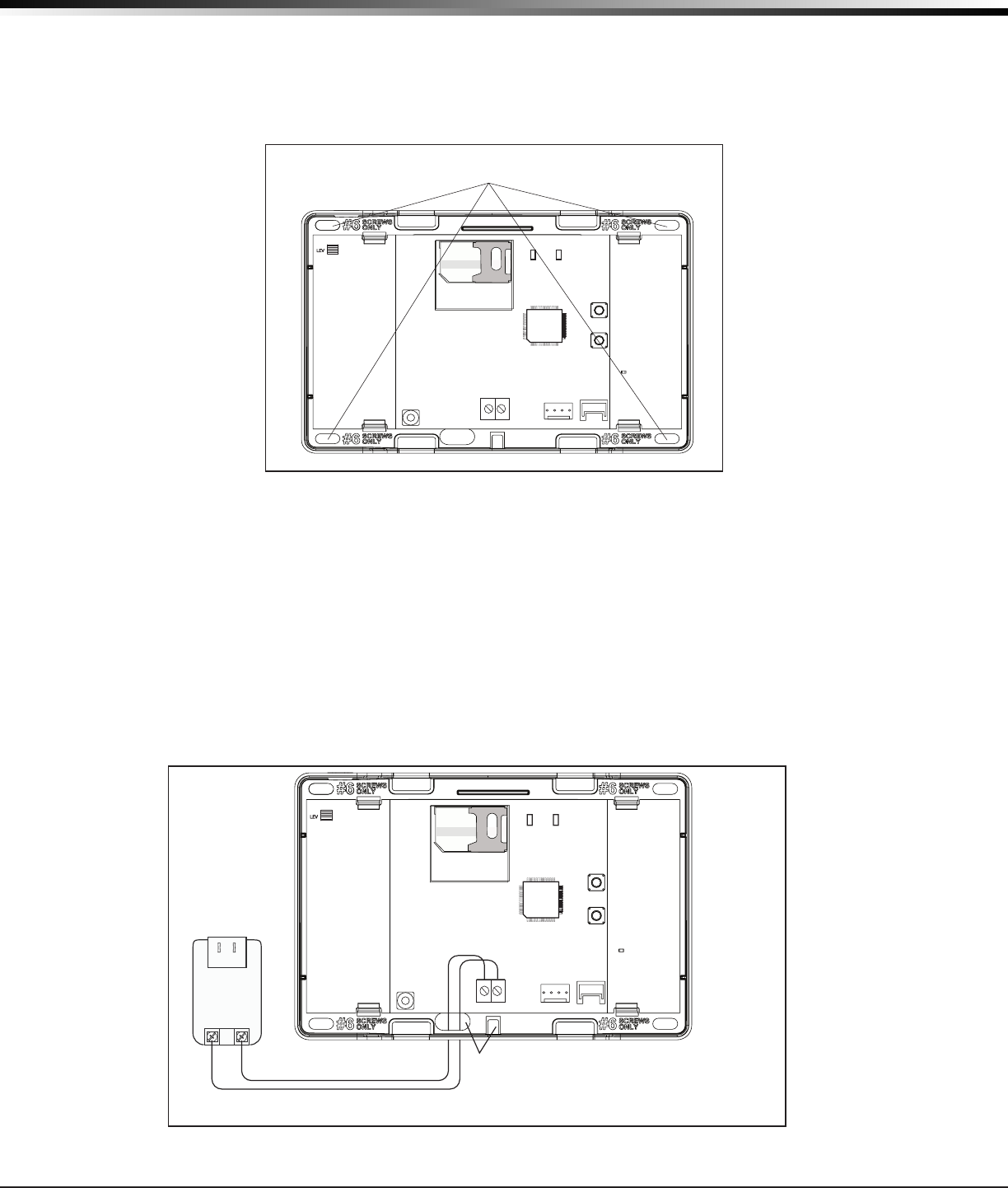
4.1 Mounting the Enclosure
TheenclosurefortheXTLpanelmustbemountedusingtheprovided#6screwsinthefourmountingholes
showninFigure2.Mounttheenclosureinasecure,dryplacetoprotectthepanelfromdamagedueto
tampering or the elements. It is not necessary to remove the PCB when installing the enclosure.
65555
RESET
S1
LOAD
S2
BAT
J1
PROG
RED
PWR
MODEL XTL
Mounting Hole
Locations
TX RF RX
Figure 2: Mounting Hole Locations
Primary Power Supply
5.1 DC Input
MounttheXTLpanelnearawalloutletfortheModel372-500plug-inDCpowersupply.Inadditionto
poweringthepanel,theDCplug-inpowersupplyalsochargestheback-upbattery.The372-500mustbe
locatedwithin100feetofthepanelusing22AWGwireor250feetusing18AWGwire.Usethefollowing
steps to connect the plug-in power supply:
1.Using18or22AWGwire,connectthepanelPWR(J2)rstterminal(+)tothepositiveterminalon
the power supply.
2.ConnectthepanelPWR(J2)secondterminal(-)tothenegativeterminalonthepowersupply.
3.Plugthepowersupplyintoa110VoltACdedicatedoutletnotcontrolledbyaswitch.
65555
RESET
S1
LOAD
S2
BAT
J1
PROG
RED
PWR
MODEL XTL
Wire Exits for DC
Power Supply
+-
TX RF RX
Model 372-500
DC Plug-in
Power
Supply
Use 18 AWG or 22 AWG for
Power Supply connection
+
_
Figure 3: DC Power Supply Connection
XTL Installation Guide Digital Monitoring Products
5
InstallatIon
Secondary Power Supply
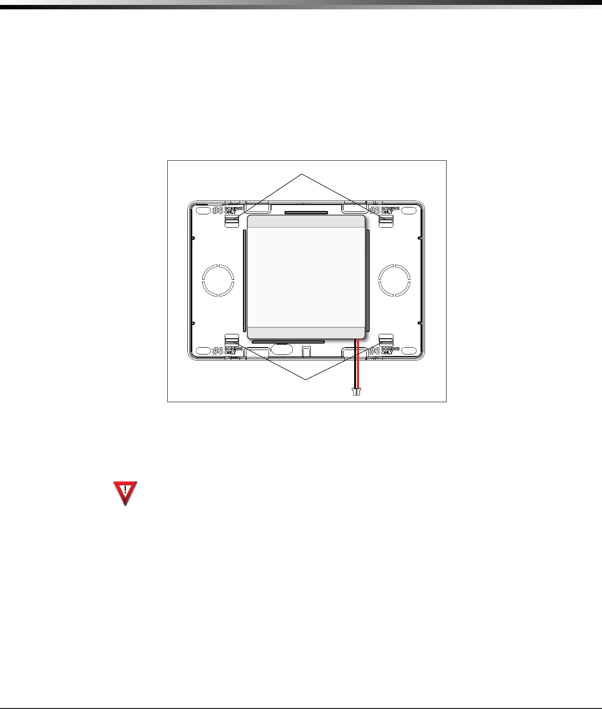
6.1 Standby Battery
TheXTLrechargeablebatteryisusedtoprovide24hoursofbackupbatterypowerwhenDCpowerisnot
available.ThebatteryisintendedforbackuppoweronlyandnottooperatetheXTLpanelonadailybasis.
Ifthebatteryislow,ornotpluggedintotheJ1batteryconnector,alowbatteryconditionisindicatedbythe
XTLpanel.
Note:IfremovingtheXTLpanelfromservice,disconnectthebackupbatteryfromtheXTLconnector.
6.2 Replacement
UsethefollowingstepstoreplacetheXTLstandbybattery.DMPrecommendsreplacingthebatteryevery3
years under normal use.
Top PCB Snaps
Bottom PCB Snaps Battery
connector
3.7V
Rechargeable
Battery
Figure 4: Standby Battery Replacement
1. Unplugthebatteryconnector(J1)fromtheXTLpanel.
2. LoosenthetopPCBsnaps.
3. LeanthepanelPCBforwardandliftoutfromthebottomPCBsnaps.
4. Removeandproperlydisposeoftheusedbattery.
Caution:Riskofre,explosion,andburns.Donotdisassemble,heatabove212°F(100°C),
or incinerate. Properly dispose of used batteries.
5. PlacethenewbatteryintotheXTLhousingbasewiththebatterywiresdirectedtowardthe
bottomrightcorner.SeeFigure4.
6. SettheXTLPCBintothebottomsnapsandpressintothetopsnapstosecureinplace.
7. Plugthebatteryintothepanelconnector(J1).
6.3 Battery Supervision
ThepanelteststhebatteryonceeveryhourwhenDCpowerispresent.Thistestoccurs15minutespast
eachhourandlastsforveseconds.Aloadisplacedonthebatteryandifthebatteryvoltageislow,alow
batteryisdetected.IfDCpowerhasfailed,alowbatteryisdetectedanytimethebatteryvoltagefalls
below3.7V.

Digital Monitoring Products XTL Installation Guide
6
InstallatIon
LED Operation
7.1 Backlit Logo
ThebacklitlogoindicatesthePowerandArmedstatusofthepanel.Dependingontheoperation,theLED
displaysinRedorGreenaslistedinthetable.
Color and Activity Operation
GreenSteady PanelDisarmed,ACPowerOK,BatteryOK
GreenBlinking PanelDisarmed,ACPowerOK,BatteryFault
NoLight PanelDisarmed,ACPowerFault,BatteryOK
RedSteady PanelArmed,ACPowerOK,BatteryOK
Red/GreenAlternate PanelArmed,ACPowerOK,BatteryFault
RedBlinking PanelArmed,ACPowerFault,BatteryOK
Reset Button
8.1 Description
Theresetbutton(S1)islocatedontherightsideofthecircuitboardandisusedtoresettheXTL
microprocessor.Toresetthepanelwhenrstinstallingthesystem,presstheresetbuttonafterapplying
power to the panel.
To reset the panel while the system is operational, for example, prior to reprogramming, press the reset
buttonfor1-2secondswithoutpoweringdownthesystem.Afterresettingthepanel,beginprogramming
within30minutes.Ifyouwaitlongerthan30minutes,youmustresetthepanelagain.
Programming Connection
9.1 Programming Connection
Alocking4-pinheader(PROG)isprovidedtoconnectakeypadwhenusingaDMPModel330Programming
Cable.ThisprovidesaquickandeasyconnectionforprogrammingtheXTLpanel.Afterprogrammingis
complete,removethekeypad.
Note:ThePROGheaderdoesnotprovideaKeypadDataBusconnection.
On-Board 1100 Series Wireless
10.1 Wireless Antenna
TheXTLWirelessAntennaisintegratedintothecircuitboard.TheXTLbuilt-inwirelessreceiveroperates
withDMP1100Seriestransmitters.Seesection3.1foralistofaccessorydevices.
10.2 LED Operation
Green (TX):ThegreenLEDasheseverytimethereceivertransmits(32timespersecond).Ifahousecode
isnotprogrammedinthepanel,thepanelisreset,orthepanelispoweredoff,thegreenLEDisoff.Under
normaloperation,thegreenLEDashesconstantlywithnointerruptionorchange.
Yellow (RX):TheyellowLEDasheseverytimethereceiverhearsamessagefromaprogrammedwireless
transmitter.Whenamessageissentbyatransmitter,typicallybypressingorreleasingthetamperswitch,
theyellowLEDshouldashindicatingthatthereceiverreceivedamessagefromthetransmitter.Ifthe
LEDneverashes,thetransmitterisnotgettingthroughtothereceiver.Thiscouldbebecauseofa
misprogrammedserialnumberorthetransmitteristoofaraway.Undernormaloperation,theyellowLED
ashesateverytripofeverywirelesstransmitterandoccasionallywhenthetransmittersperformtheir
periodiccheck-in.ItisnotunusualforthisLEDtostayoffformanyminutesatatimewhennotransmitters
are communicating.

XTL Installation Guide Digital Monitoring Products
7
InstallatIon
Wireless Keypads
11.1 Mounting Keypads
DMPkeypadshaveremovablecoversthatallowthebasetobemountedonawallorotheratsurfaceusing
the screw holes provided on each corner.
11.2 Wireless Keypad Association
Pressingtheresetbutton3timeswithin5secondsenablesthekeypadassociationmode.Foroneminute
thepanellistensforwirelesskeypads.Anykeypadsnotalreadyassociatedwithanotherpanelareaccepted.
Therstkeypaddetectedisassignedtotherstopenkeypadaddress.Keypadsareautomaticallyassigned
addressesbasedupontheorderinwhichtheyaredetected.Amaximumof4keypadsmaybeassociated
with a panel.
11.3 Existing Keypad Conrmation
Duringtheoneminutetimeperiod,thepanelalsoconrmsthatprogrammedkeypadsarestillfunctioning.
Wireless Zones
12.1 Description
XTLpanelsprovide28wirelesszonesnumbered1to28.Thedefaultzonenamesaredescribedbelow.
Zone Number Zone Name Zone Type Area Assignment
1 FRONT DOOR EX PERIM
2 BACK DOOR EX PERIM
3 INTERIOR DOOR NT INT
4 UPSTAIRS DOOR EX PERIM
5 BASEMENT DOOR EX PERIM
6 GARAGE DOOR EX PERIM
7 WAREHOUSE DOOR EX PERIM
8 SHIPPING DOOR EX PERIM
9 BREAKROOM DOOR NT INT
10 STOCKROOM DOOR NT INT
11 FRONT MOTION NT INT
12 BACK MOTION NT INT
13 INTERIOR MOTION NT INT
14 UPSTAIRS MOTION NT INT
15 BASEMENT MOTION NT INT
16 GARAGE MOTION NT INT
17 GLASSBREAK NT INT
18 WATER DETECTOR AUX 1 INT
19 LOW TEMPERATURE AUX 1 INT
20 SMOKE DETECTOR FI
21 FRONT SMOKE FI
22 BACK SMOKE FI
23 INTERIOR SMOKE FI
24 UPSTAIRS SMOKE FI
25 BASEMENT SMOKE FI
26 GARAGE SMOKE FI
27 WAREHOUSE SMOKE FI
28 SHIPPING SMOKE FI

Digital Monitoring Products XTL Installation Guide
8
InstallatIon
Flash Load Button
13.1 Description
TheXTLpanelsoftwarecanbeupdatedviathepanel’sprogramming(PROG)header.Toupdatethepanel
with a new software version, complete the following steps at the protected premise:
1. ConnectaDMP399CablefromtheProgrammingHeadertotheserialportofyourPCoperating
RemoteLinkandcontainingtheXTLRUle.
3. StartRemoteLinkandcreateoropentheXTLcontrolpanelaccountthatmatchesthepaneltobe
updated.
4. SettheConnectionInformationTypetoDirectwithabaudrateof38400andchoosethe
appropriateCOMport.
5. SelectPanel>RemoteUpdate,thenselectthecorrectRUlefortheXTpanelmodel.
6. PressandholdtheLOADbutton(S2),thenpressandreleasetheRESETbutton.
7. ReleasetheLOADbuttonandclick<Update>inRemoteLink.
8. Afterthesoftwareupdateiscompleted,removethe399cableandpresstheRESETbuttonto
resume normal panel operation.

XTL Installation Guide Digital Monitoring Products
9
InstallatIon
Listed Compliance Specications
14.1 Introduction
Theprogrammingandinstallationspecicationscontainedinthissectionmustbecompletedwheninstalling
theXTLinaccordancewithanyoftheANSI/ULburglarystandards.Additionalspecicationsmayberequired
by a particular standard.
14.2 Use Marking
CommercialCentralStation;HouseholdFireandBurglarWarningSystemControlUnit(Cellular)
14.3 NFPA 72
ThisequipmentshouldbeinstalledinaccordancewithChapter11oftheNationalFireAlarmCode,ANSI/
NFPA72-2002,(NationalFireProtectionAssociation,BatterymarchPark,Quincy,MA02269).Printed
information describing proper installation, operation, testing, maintenance, evacuation planning, and repair
serviceistobeprovidedwiththisequipment.Warning:Owner’sinstructionnotice,nottoberemovedby
anyone except occupant.
14.4 Types Of Service
SuitableforCentralStationStandardLineSecurity.SuitableforHouseholdFireandHouseholdBurglary.Test
weekly.
14.5 Bypass Reports
ThebypassreportsmustbeprogrammedasYESforalllistedburglaryapplications.
14.6 Battery Standby
TheXTLisshippedwithabatteryfor24hourbatterystandbyoperation.
Household Burglar-Alarm System Units
ANSI/UL 1023
15.1 Bell Cutoff
The bell cutoff time cannot be less than four minutes.
15.2 Entry Delay
Themaximumentrydelayusedmustnotbemorethan45seconds.
15.3 Exit Delay
The maximum exit delay used must not be more than 60 seconds.
15.4 Wireless External Contact
Whenused,theExternalContactof1101or1102mustbeprogrammedNormallyClosed.
15.5 Wireless Supervision Time
TheZoneInformationSupervisionTimecannotbesetto0(zero).
15.6 Wireless Audible Annunciation
TheWirelessAudibleoptionmustbeselectedasDAYforresidentialapplications.
15.7 Panel location
Mountpanelinsideprotectedarea.
15.8 Test Frequency
TheTestFrequencyoptionmustbeprogrammedtosendareportatleastonceevery30days.

Digital Monitoring Products XTL Installation Guide
10
ComPlIanCe
Central Station Burglar Alarm Units
ANSI/UL 1610
16.1 Standard Line Security
StandardLineSecurityisprovidedwhentheCheck-intimeissetto3minutes.Whenprogrammedfor
StandardLineSecurity,ExitTimeRestartisdisabled.
Note:TheSecureComWirelesstextplanselectedforthepanelshouldmatchorexceedtheprogrammed
MonthlyLimitoradditionalcellularchargesmayapply.
16.2 Remote Disarm
REMOTEDISARMmustbeprogrammedasNO.
16.3 Central Station
MESSAGETOTRANSMITprogrammingforzonesmustnotbesettoLOCAL(L).
Household Fire Warning System
ANSI/UL 985 NFPA 72 Specications
17.1 Bell Output Denition
ThebelloutputoftheXTLpanelmustbeprogrammedtooperatesteadyonburglaryalarmsandtemporal
onrealarms.SeetheXTLProgrammingGuide.
17.2 Household System
An alarm sounding device must be installed indoors so that it is clearly heard in all sleeping areas.
17.3 Wireless External Contact
Whenused,theExternalContactof1101or1102mustbeprogrammedNormallyClosed.SeetheXTL
ProgrammingGuide.
17.4 Wireless Supervision Time
TheZoneInformationSupervisionTimemustbe3minutesforredevices.SeetheXTLProgrammingGuide.
17.5 Wireless Fire Verication
Whenused,theModel1161and1162wirelesssmokedetectorsmustnotbeprogrammedasFireVerication
(FV)zonetype.SeetheXTLProgrammingGuide.
17.6 Battery Standby
ForULlistedapplications,thepanelmusthave24hourbatterystandbyoperation.
17.7 Test Frequency
TheTestFrequencyoptionmustbeprogrammedtosendareportatleastonceevery30days.

XTL Installation Guide Digital Monitoring Products
11
ComPlIanCe
False Alarm Reduction Programmable Options ANSI/SIA CP-01-2007
18.1 Shipping Defaults and Recommended Programming
SIA CP-01 FEATURE
PARAGRAPH # AND
DESCRIPTION
DMP PROGRAMMING
GUIDE LT-1108
SECTION #
REQUIREMENT RANGE SHIPPING
DEFAULT
RECOMMENDED
PROGRAMMING*
4.2.2.1ExitTime 8.6ExitDelay Required
(Programmable) 45sec.-250sec. 60
Seconds 60Seconds
4.2.2.2Progress
Annunciation
13.14Prewarn
Address Allowed
Individualkeypads
may be disabled per
zone
All
keypads
enabled
Allkeypadsenabled
4.2.2.3ExitTime
Restart 8.6ExitDelay RequiredOption For re-entry during
exit time Enabled Enabled
4.2.2.5AutoStayArm
onUnvacatedPremises
8.17Occupied
Premise - SeeInstall
Guide
RequiredOption
(exceptfor
remotearming)
OccupiedPremise
NO/YESoption Enabled
EnabledYes
for Residential
Applications
4.2.4.4ExitTimeand
Progress Annunciation/
Disable-forRemote
Arm
NotAvailableon
Remote Arming AllowedOption
Progress Annunciation
Always disabled for
Remote Arming
Not
Available
Remote Arming not
allowed for CP-01
installations.
4.2.3.1EntryDelay(s) 8.5EntryDelay Required
(Programmable) 30sec.–240Sec.** 30
Seconds Atleast30Seconds**
4.2.5.1AbortWindow–
forNon-FireZones 3.3TransmitDelay RequiredOption Disablebyzoneor
zonetype
Enabled
NTDY
EXZone
Enabled
4.2.5.1AbortWindow
Time–forNon-Fire
Zones
3.3TransmitDelay Required
(Programmable)
20sec.,30sec.,or
40sec.**
30
Seconds Atleast20Seconds**
4.2.5.1.2Abort
Annunciation 3.3TransmitDelay RequiredOption
Annunciate that
no alarm was
transmitted
Yes Yes
4.2.5.4.1Cancel
Annunciation
AlwaysEnabled-Not
Programmable RequiredOption
Annunciate that
a Cancel was
transmitted(S49)
Always
Enabled Yes
4.2.6.1&4.2.6.2
DuressFeature
UserCode+1=
AmbushCodeNot
Available
AllowedOption
No1+derivativeof
another user code/no
duplicates with other
user codes
Code+1
Always
Disabled
NotProgrammable
4.3.2SwingerShutdown NotAvailable—
AlwaysOn Required
Forallnon-re
zones,shutdown
after 1 trip
Always
On AlwaysOn
4.3.2SwingerShutdown
Disable 13.13SwingerBypass Allowed For non-police
responsezones Yes Enabled(allzones)
4.3.3FireAlarm
Verication 13.5ZoneType RequiredOption FV Type Zone No
Yes as required
(unlesssensorscan
selfverify)
* Programming at installation may be subordinate to other listed requirements for the intended application.
**ForlistedInstallations,combinedEntryDelayandTransmitDelayshouldnotexceed1minute.

Digital Monitoring Products XTL Installation Guide
12
ComPlIanCe
False Alarm Reduction Programmable Options ANSI/SIA CP-01-2007
(continued)
18.2 Entry Delay
OnlyuseEntryDelay1.DonotuseEntryDelay2.SeetheXTLProgrammingGuide.
18.3 Local Bell
Allnon-rezonessuchasNight,Day,Exit,Aux1andAux2mustbeprogrammedforlocalbellenabledwith
a bell cutoff time set to a minimum of 6 minutes to provide a cancel window of 5 minutes or greater. This
doesnotapplytomanuallyoperatedzonetypessuchasPanicandEmergency.
TherequirementsaresupercededbyanyrequirementsforCommercialBurglar,HouseholdFireWarning,or
Household Burglar applications.
18.4 Minimum Installation Requirements
SIACP-01-2007minimumsysteminstallationrequirementsincludeanXTL,an1135WirelessSiren,and
communicationtoanSCS-1Rreceiverplusa9000SeriesWirelesskeypad.

XTL Installation Guide Digital Monitoring Products
13
revIsIons
Revisions to This Document
This section explains the changes that were made to this document during this revision. This section lists
theversion,sectionnumberwithheading,andaquicksummaryofthechange.
Ver. Section Number and Heading Summary of Changes

LT-11051.01©2010DigitalMonitoringProducts,Inc.
800-641-4282
www.dmp.com
MadeintheUSA
INTRUSION•FIRE•ACCESS•NETWORKS
2500NorthPartnershipBoulevard
Springfield,Missouri65803-8877
10045
Listings and Approvals
FCCPart15ID:CCKPC0117
IndustryCanadaID:5251A-PC0117
UnderwritersLaboratories(UL)Listed
ANSI/UL1023 HouseholdBurglar
ANSI/UL985 HouseholdFireWarning
ANSI/UL1610 CentralStationBurglar