Digital Monitoring PC0131 LOW POWER TRANSCEIVER User Manual
Digital Monitoring Products Inc LOW POWER TRANSCEIVER Users Manual
UserManual.wiki
>
Digital Monitoring
>
PC0131 User Manual
Users Manual
Navigation menu
Upload a User Manual
Namespaces
Wiki Guide
HTML
PDF
Info
Views
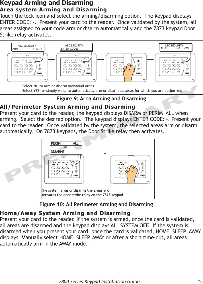
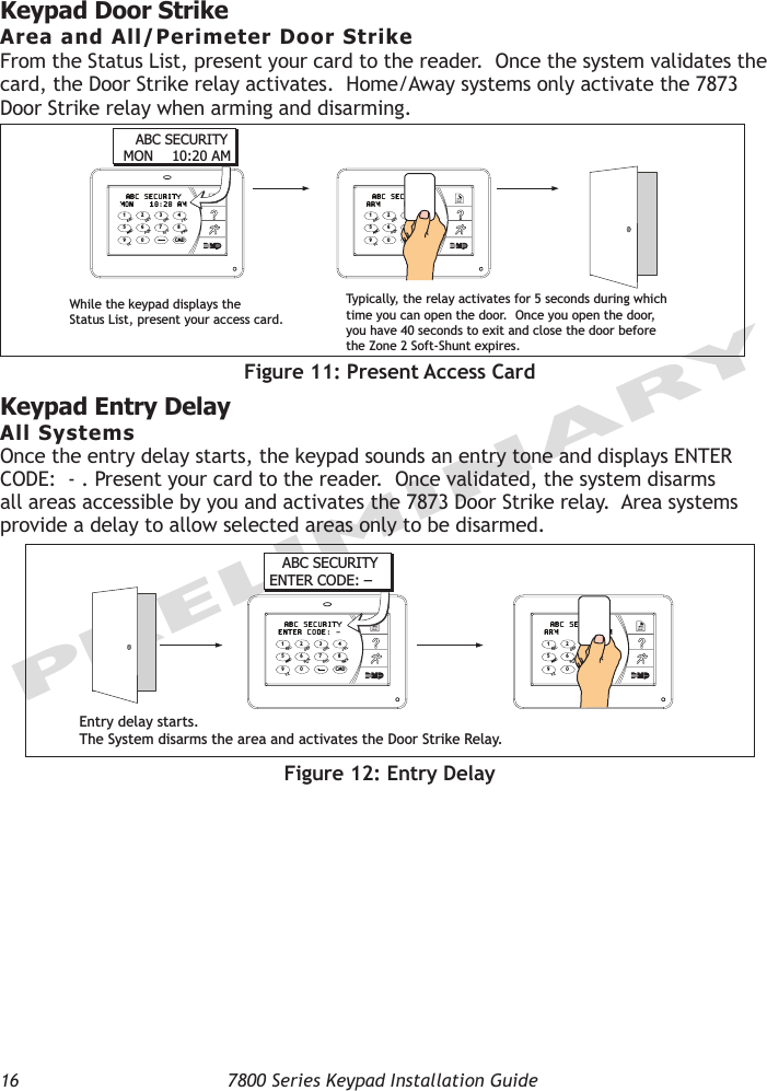
User Manual
Discussion / Help
Navigation