Digital Monitoring PC0156 Personal Emergency Response Base Unit User Manual
Digital Monitoring Products Inc Personal Emergency Response Base Unit
Contents
- 1. User Manual
- 2. Installation Guide
User Manual
LT-1329 © 2014 LifeStation
14475
LifeStation
®
Call us toll free at 877.833.2020
LifeStation
Call us toll free at 877.833.2020
LifeStation
CANCEL
TROUBLE
COMM
STATUS
TEST
POWER
Bracelet Clip
Bracelet Clip
Lanyard Clip
Lanyard Clip
TELEPHONE
Wall Jack
ELECTRICAL
Wall Jack
16.5 V AC
HOUSE PHONE
VOLUME
PHONE LINE
EM20D
Console
Home Phone
16.5Vac
Power
Adapter
“Now we will test the range of your
emergency pendants in various rooms.
Press the help button when you are ready
to start the range test.”
Step 5. Setting up your Help Button
“Press each emergency pendant in each
room. Press the help button to complete
the test.”
When a pendant or help button is detected:
“Pendant detected.”
“Thank you, we have now nished setting
up your communicator. Congratulations!
Please press your help button to send
your rst call to the personal response
associate.”
Press the help button
Step 6. Placing a Test Call
Press and release the Test Button within 3 seconds to place a test call.
“Test call is now being placed.
Please stand by.”
If you do not get a response, review Step 3.
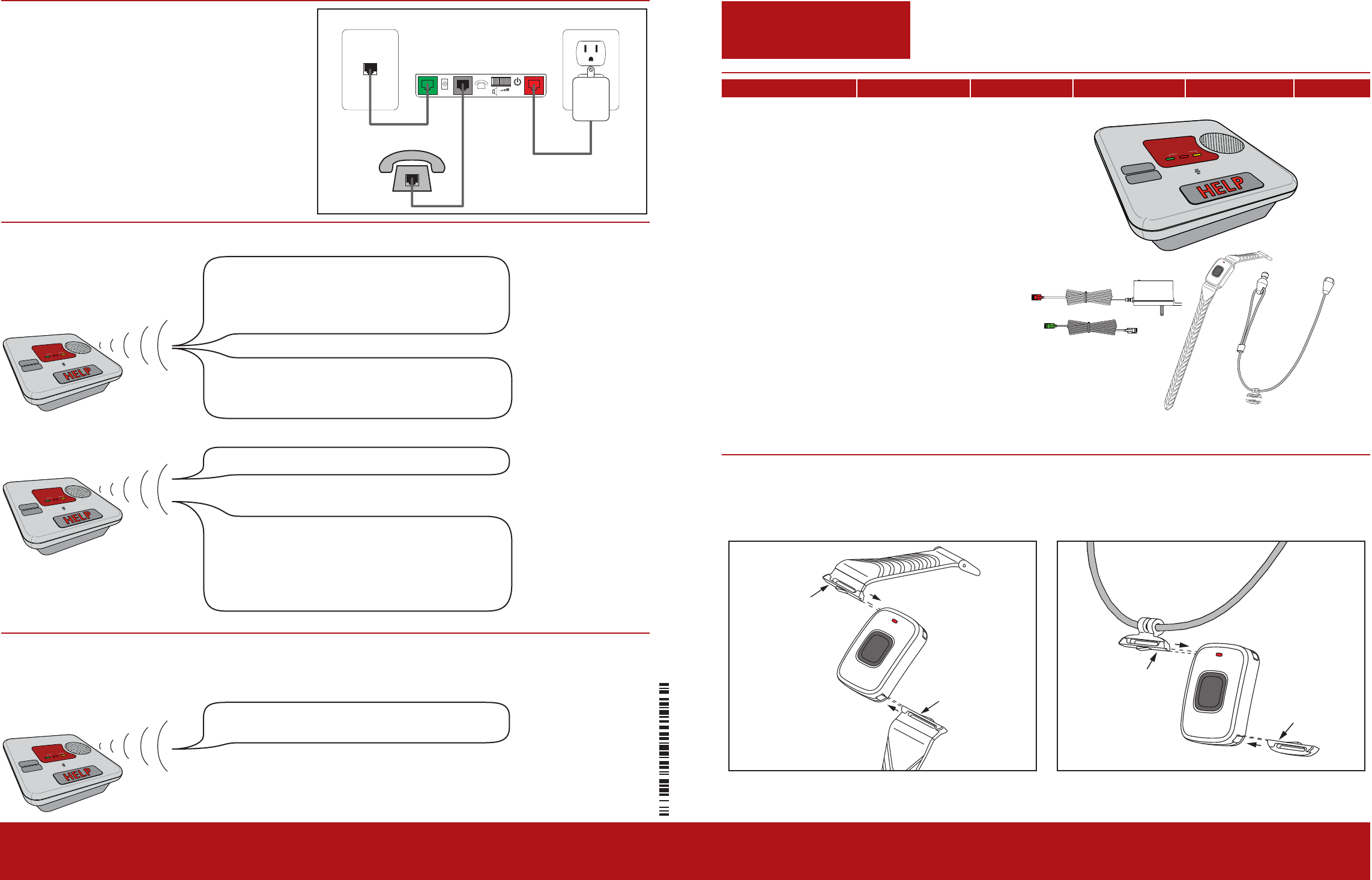
Step 4. Connecting your Home Phone
Connect your home phone cord to the gray
connection on the back of the Console.
Choose either the wrist strap or break-away lanyard option for the 1148 Emergency Pendant.
Step 1. Selecting your Help Button Option
Quick Start Guide
SELECTING YOUR HELP BUTTON OPTION CONNECTING THE POWER SUPPLY CONNECTING THE PHONE LINE CONNECTING YOUR HOME PHONE SETTING UP YOUR HELP BUTTON PLACING A TEST CALL
What is Included
• One EM20 Console
• One 12V DC Battery -
installed
• Color-coded phone cord
• 16.5VAC Power Adapter
• 1148 Emergency Pendant
Wrist strap
Break-away Lanyard
CANCEL
TROUBLE
COMM
STATUS
TEST
POWER
CANCEL
TROUBLE
COMM
STATUS
TEST
POWER
CANCEL
TROUBLE
COMM
STATUS
TEST
POWER
PRELIMINARY
PRELIMINARY
Call us toll free at 877.833.2020 if you need any assistance in setting up your system.
LifeStation
Step 2. Connecting the Power Supply
CANCEL
TROUBLE
COMM
STATUS
TEST
POWER
13.6 V AC
VOLUME
PHONE LINE HOUSE PHONE
13.6 V AC
VOLUME
PHONE LINE HOUSE PHONE
1. Unpack the power supply and fully
unroll the cord.
2. Connect the power supply to the red
connection on the back of the Console.
3. Connect the power supply to an
electrical outlet and secure with the
provided screw through tab on the
power supply.
CANCEL
TROUBLE
COMM
STATUS
TEST
POWER
“Welcome! We will now help you setup
your communicator step-by-step. If you
miss a step, wait, and we will repeat the
instructions.”
Step 3. Connecting the Phone Line
1. Unpack the color-coded phone cord and
fully unroll.
If no phone line is detected within one minute:
“Good, your communicator is now plugged
in. You may press the help button to
continue.”
“Your communicator has not been
correctly plugged in to the phone line. See
step 3 in the quick start guide.”
The Voice Prompt Setup begins automatically when
power is applied. The setup cannot be exited until
completed. If power is somehow interrupted and the
setup does not complete, it will start over when power
is restored. During the Voice-Prompt Setup the last
message will repeat once for each minute of inactivity.
“Please nd the quick start guide located
in the box. When you have the guide in
front of you, press the help button.”
2. Connect the color-coded phone cord to
the green connection on the back of the
Console.
Next, we will plug the gray phone cord into
a phone jack in the wall. You may need
to unplug your phone temporarily, and
reconnect it in the next step.”
CANCEL
TROUBLE
COMM
STATUS
TEST
POWER
CANCEL
TROUBLE
COMM
STATUS
TEST
POWER
Next, we will plug your phone into the back
of the communicator if necessary. Refer to
step 4 in the quick start guide. Please press
the help button to continue.”
When a phone line is detected:
When power is applied, the Voice Prompt
Setup begins.
3. Connect the opposite end to the phone
wall jack.
PRELIMINARY
PRELIMINARY