Digital Monitoring PC0156 Personal Emergency Response Base Unit User Manual Installation Guide
Digital Monitoring Products Inc Personal Emergency Response Base Unit Installation Guide
Contents
- 1. User Manual
- 2. Installation Guide
Installation Guide
InstallatIon GuIde
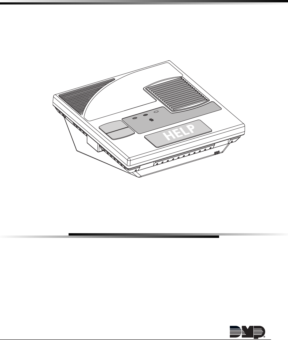
EM20 PERSONAL EMERGENCY
RESPONSE SYStEM CONSOLE
CANCEL
TEST
TROUBLE
COMM
POWER TROUBLE
COMM
POWER

MODEL EM20
INSTALLATION GUIDE
FCC NOTICE
This equipment has been tested and found to comply with the limits for a Class B digital device, pursuant
to part 15 of the FCC Rules. These limits are designed to provide reasonable protection against harmful
interference in a residential installation. This equipment generates, uses and can radiate radio frequency
energy and, if not installed and used in accordance with the instructions, may cause harmful interference
to radio communications. However, there is no guarantee that interference will not occur in a particular
installation. If this equipment does cause harmful interference to radio or television reception, which can be
determined by turning the equipment off and on, the user is encouraged to try to correct the interference
by one or more of the following measures:
• Reorient or relocate the receiving antenna.
• Increase the separation between the equipment and receiver.
• Connect the equipment into an outlet on a circuit different from that to which the receiver is
connected.
• Consult the dealer or an experienced radio/TV technician for help.
Changesormodicationsnotexpresslyapprovedbythepartyresponsibleforcompliancecouldvoidthe
user’s authority to operate the equipment.
This device has been designed to operate with the integrated 1100 Series PCB antenna having a maximum
gain of 1.8 dB. Antennas having a gain greater than 1.8 dB are strictly prohibited for use with this device.
The required antenna impedance is 50 ohms.
If necessary, the installer should consult the dealer or an experienced radio/television technician
foradditionalsuggestions.Theinstallermayndthefollowingbooklet,preparedbytheFederal
Communications Commission, helpful:
“How to identify and Resolve Radio-TV Interference Problems.”
ThisbookletisavailablefromtheU.S.GovernmentPrintingOfce,WashingtonD.C.20402
StockNo.004-000-00345-4
Industry Canada Information
ThisdevicecomplieswithIndustryCanadaLicence-exemptRSSstandard(s).Operationissubjecttothe
followingtwoconditions:(1)thisdevicemaynotcauseinterference,and(2)thisdevicemustacceptany
interference, including interference that may cause undesired operation of the device.
LeprésentappareilestconformeauxCNRd’IndustrieCanadaapplicablesauxappareilsradioexemptsde
licence. L’exploitation est autorisée aux deux conditions suivantes : (1) l’appareil ne doit pas produire de
brouillage,et(2)l’utilisateurdel’appareildoitacceptertoutbrouillageradioélectriquesubi,mêmesile
brouillage est susceptible d’en compromettre le fonctionnement.
©2015DigitalMonitoringProducts,Inc.
InformationfurnishedbyDMPisbelievedtobeaccurateandreliable.
Thisinformationissubjecttochangewithoutnotice.
Caution Notes
Throughoutthisguideyouwillseecautionnotescontaininginformationyouneedtoknowwheninstalling
theEM20.Thesecautionsareindicatedwithayieldsign.Wheneveryouseeacautionnote,makesureyou
completely read and understand its information. Failing to follow the caution note can cause damage to the
equipment or improper operation of one or more components in the system.

Table of ConTenTs
Digital Monitoring Products
iii
Specications
1.1 Power Supply ..................................................................................................... 1
1.2 Communication ................................................................................................... 1
1.3 EnclosureSpecications ...................................................................................... 1
Introduction
2.1 SystemCongurations ......................................................................................... 1
System Components
3.1 WiringDiagram ................................................................................................... 1
3.2 AccessoryDevices ............................................................................................... 1
Installation
4.1 Location Information ........................................................................................... 2
Primary Power Supply
5.1 AC Power Supply ................................................................................................ 2
Secondary Power Supply
6.1 Standby Battery .................................................................................................. 2
6.2 BatterySupervision ............................................................................................. 2
Status Light Operation
7.1 StatusLights ...................................................................................................... 3
Programming Connection
8.1 ProgrammingConnection .................................................................................... 3
8.2 LowPowerShutdown .......................................................................................... 3
On-Board 1100 Series Wireless
9.1 Wireless Antenna ................................................................................................ 3
Telephone Connections
10.1 Telephone .......................................................................................................... 4
10.2 Cellular .............................................................................................................. 4
10.3 FCCRegistration ................................................................................................. 4
10.4 Notication ......................................................................................................... 4
10.5 CS-03RegistrationInformation ............................................................................ 4
EM20 Personal Emergency Response System Console Compliance
HomeHealthCareSignalingEquipment .............................................................................. 5
ANSI/UL 1637/1635 ........................................................................................................... 5
11.1 HomeHealthCareSignalingEquipment ................................................................ 5
InstallatIon
Digital Monitoring Products
1
Specications
1.1 Power Supply
Input: 16.5VAC
StandbyBattery: 12VSealedLeadAcid
1.2 Communication
EM20C Cellular Communicator
TheCellularcommunicatorusesDMPModel264CCDMAtocommunicatewiththeCentralStationreceiver.
EM20D Dialer Communicator
TheDialercommunicatorusesdigitaldialerlinetocommunicatewiththeCentralStationreceiver.
1.3 EnclosureSpecications
TheEM20shipsinaplasticenclosurewithaQuickStartGuide(LT-1329)andUserGuide(LT-1347).
Size Color
6.5”Wx6.5”Hx2.95”D White
Introduction
2.1 SystemCongurations
TheEM20canbeprogrammedwith16wirelesszones.
System Components
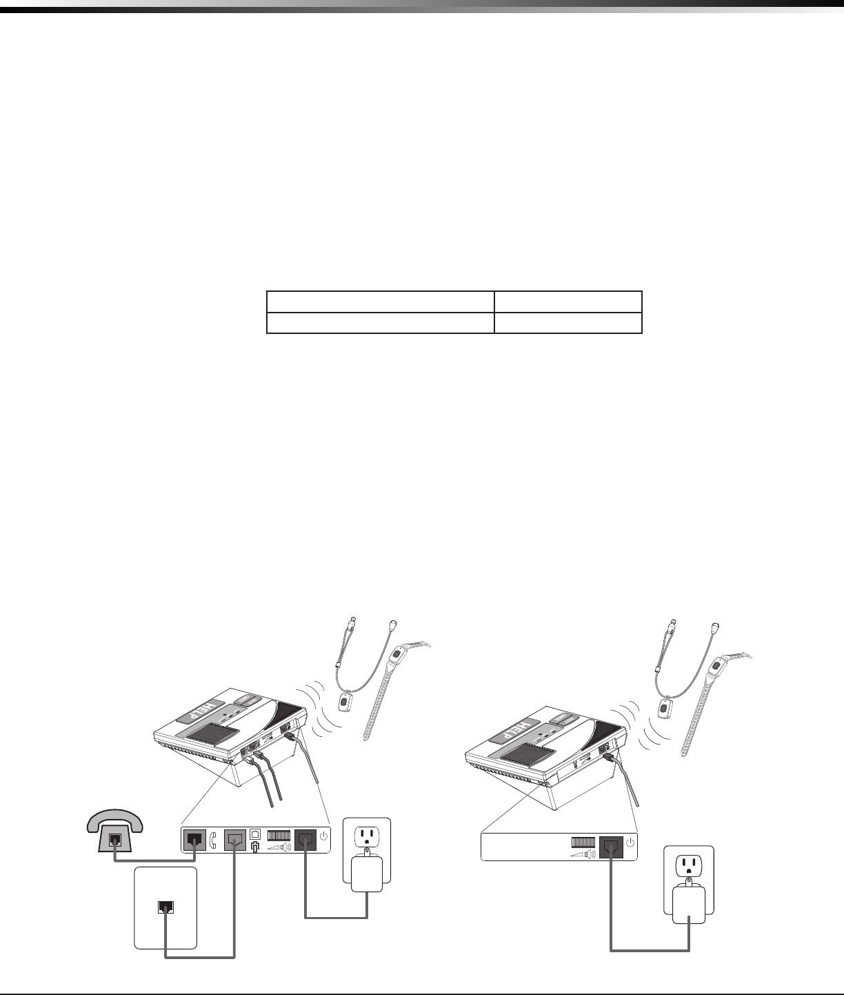
3.1 Wiring Diagram
The system wiring diagram in Figure 1 shows some of the accessory devices for use in various applications. A
description of each module follows.
3.2 Accessory Devices
• 1141WallButton
• 1148PersonalPendantwithLanyardandWristband
TELEPHONE
Wall Jack
ELECTRICAL
Wall Jack
EM20D
Console
Home Phone
1148 Personal Pendant
or Wristband
16.5V AC
Power
Adapter
16 VDC
EM20D
ELECTRICAL
Wall Jack
EM20C
Console
1148 Personal Pendant
or Wristband
16.5V AC
Power
Adapter
16 VDC
EM20C
Figure 1: Wiring Diagrams for Cellular and Dialer
InstallatIon
Digital Monitoring Products
2
Installation
4.1 Location Information
A location should be selected that is centrally located between the 1100 Series transmitters used in the
installation.PlacetheEM20awayfrommetalobjects.PlacingtheEM20onornearmetalsurfacesimpairs
performance.
Primary Power Supply
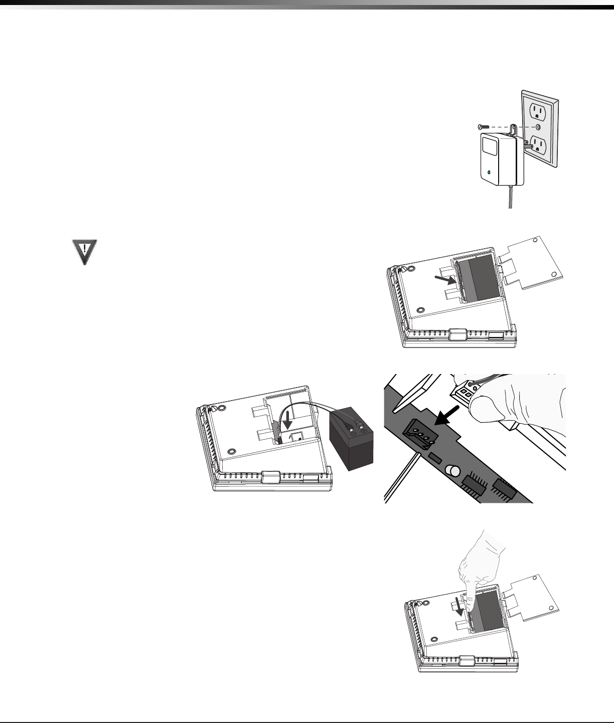
5.1 AC Power Supply
1. Unpackthe16.5VACpowersupplyandfullyunrollthecord.
2. ConnectthepowersupplytotheRedRJ22connectiononthebackoftheEM20.
3. Connect the power supply to a 120VAC outlet not controlled by a switch and
secure with the screw provided.
Secondary Power Supply
6.1 Standby Battery
Install the Battery
Observe polarity when connecting battery. Ensure the
battery harness connectors are fully inserted to prevent
shorting.
1. TurntheEM20overandremovebatterycover.
2. The new battery comes with the harness pre-installed.
3. Connect the new battery harness to the locking 4-pin header
battery connector inside the battery compartment. Because the
headeriskeyed,itcanonlybeinstalledinonedirection.
4. Re-installthebatterycoverandturntheEM20upright.
6.2 Battery Supervision
TheEM20teststhebatteryonceeveryhourwhenACpowerispresent.
Thistestoccurs15minutespasteachhourandlastsforveseconds.
A load is placed on the battery and if the battery voltage falls below
11.9V, a low battery is detected.IfDCpowerhasfailed,alowbatteryis
detectedanytimethebatteryvoltagefallsbelow11.9V.
Figure 3: Step 2 & 3.
Figure 2: Step 1.
Figure 4: Step 4.

INStALLAtION
Digital Monitoring Products
3
Status Light Operation
7.1 Status Lights
Each StatusLightindicatesthecurrentstatusoftheEM20
Console.
Green POWER Light
Off............ NoACPower.Checkpowercordispluggedin.
Blinking ...... AC Power Adapter is plugged in but the battery is
low.
OnSteady .. AC Power and battery good. This is normal.
Red COMM Light
Off............ Normal
Blinking ...... Notelephonelineorcellularconnectiondetected.
OnSteady .. Connected to an operator or sending a message.
Yellow TROUBLE Light
Off............ Normal
Blinking ...... PressandreleasetheCANCELButtontoresetactivityonconsole.
OnSteady .. System troubles such as low battery on pendant or missing pendant.
Programming Connection
8.1 Programming Connection
Alocking4-pinheaderisprovidedtoconnecttheRemoteLinkcomputerwhenusingaDMPModel399
ProgrammingCabletoprogramtheunit.Afterprogrammingiscomplete,removetheModel399Programming
Cable.
Note:TousetheprogrammingheaderwiththeDMPModel399ProgrammingCable,youmustremovethe
batteryconnector.Thesame4-pinheaderisusedforprogrammingandforchargingthebattery.
8.2 Low Power Shutdown
UsingRemoteLinkProgrammingSoftware,LowPowerShutdowncanbeenabledtopreservethebattery
during shipment to the end user by shutting down the processor until AC Power is restored to the unit and
Voice Prompt Setup is completed.
On-Board 1100 Series Wireless
9.1 Wireless Antenna
TheEM20WirelessAntennaisintegratedintothecircuitboard.Thebuilt-inwirelessreceiveroperates
withtheDMP1141and1148transmitters.SeesectionSystemComponents/AccessoryDevicesforalistof
accessory devices.
TROUBLE
COMM
POWER
CANCEL
TEST
HELP
Figure 5: Status Lights
Digital Monitoring Products EM20 PERS Installation Guide
4
InstallatIon
Telephone Connections
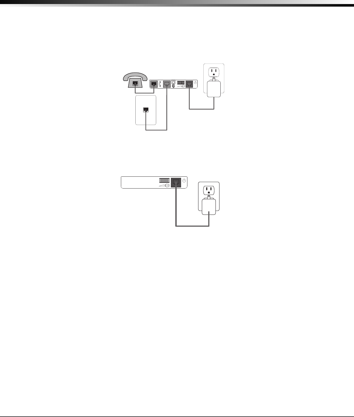
10.1 Telephone
Connect the House Phone
1. Unpackthecolor-codedphonewireandfullyunroll.
2. ConnecttheGreenwiretotheGreenRJ11ConnectoronthebackofEM20.
3. ConnecttheoppositeendoftheGreenwiretothehousephonewallconnection.
10.2 Cellular
Connect to Cellular Network
1.WhenACpowerisapplied,theEM20Cwillbeginsearchingforcellularsignal.
10.3 FCC Registration
The panel complies with FCC part 68 and is registered with the FCC.
Registrationnumber:CCKAL01BXEM20
Ringer Equivalence: 0.1 B
10.4 Notication
Registered terminal equipment must not be repaired by the user. In case of trouble, the device must be
immediatelyunpluggedfromthetelephonejack.Thefactorywarrantyprovidesforrepairs.Registered
terminalequipmentmaynotbeusedonpartylinesorinconnectionwithcointelephones.Noticationmust
be given to the telephone company with the following information:
a. The particular line(s) the service is connected to
b. The FCC registration number
c. The ringer equivalence
d.Themake,model,andserialnumberofthedevice
10.5 CS-03 Registration Information
ThisproductmeetstheapplicableIndustryCanadatechnicalspecications.
Leprésentmatérielestconformeauxspecicationstechniquesapplicablesd’IndustrieCanada.
TheRingerEquivalenceNumber(REN)isanindicationofthemaximumnumberofdevicesallowedtobe
connected to a telephone interface. The termination of an interface may consist of any combination of
devicessubjectonlytotherequirementthatthesumoftheRENsofallthedevicesnotexceedve.
L’indiced’équivalencedelasonnerie(IES)sertàindiquerlenombremaximaldeterminauxquipeuventêtre
raccordés à une interface téléphonique. La terminaison d’une interface peut consister en une combinaison
quelconque de dispositifs, à la seule condition que la somme d’indices d’équivalence de la sonnerie de tous
les dispositifs n’excède pas cinq.
TELEPHONE
Wall Jack
ELECTRICAL
Wall Jack
EM20D
Console
Home Phone
16.5Vac
Power
Adapter
16 VDC
Figure 6: Telephone Connections.
ELECTRICAL
Wall Jack
EM20C
Console
16.5V AC
Power
Adapter
16 VDC
Figure 7: Cellular Connections.

800-641-4282
www.dmp.com 2500 North Partnership Boulevard
LT-1346 © 2015 Digital Monitoring Products, Inc.
15415
Patents
U.S.PatentNo.7,239,236
Certications
FCCPart15RegistrationIDCCKPC0156Pending
IndustryCanadaID:5251A-PC0156
Specications
Battery
LifeExpectancy 2years(normal
operation)
Type 12VLeadAcid
FrequencyRange: 905-924MHz
Dimensions
BaseUnitCase 6.5”Lx6.5”Wx2.95”H
Color White
Ordering Information
EM20DDialerCommunicator
EM20CCellularCommunicator
Accessories
1141WallButton
1148PersonalPendantwithLanyardand
Wristband
EM20 Personal Emergency Response System Console Compliance
Home Health Care Signaling Equipment
ANSI/UL 1637/1635
11.1 Home Health Care Signaling Equipment
1. Powerfailhoursneedstobesetto8hoursorlessinSystemOptions.
2. Addthecharacter“D”tothebeginningofaphonenumberinCommunicationsfortheEM20to
wait for a dial tone before dialing.
COMPLIANCE