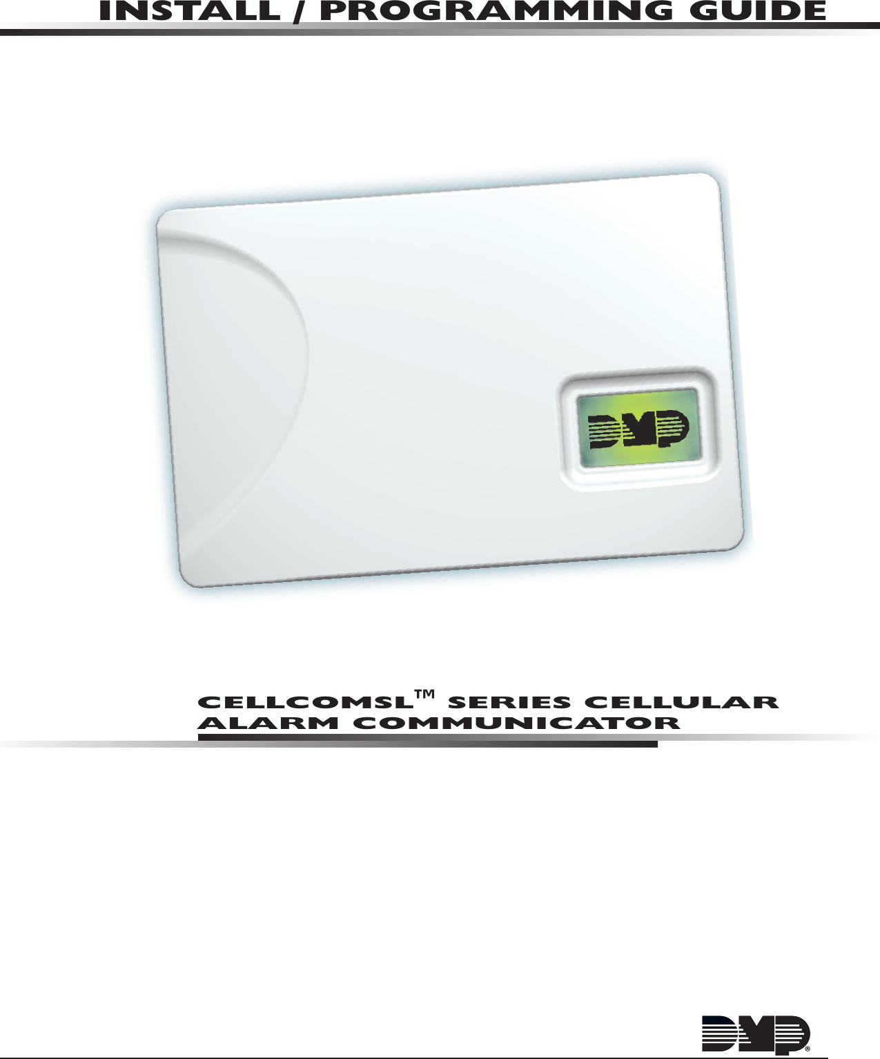
Digital Monitoring PC0159 Low Power Wireless Transceiver User Manual USERS MANUAL

Digital Monitoring Products Inc Low Power Wireless Transceiver USERS MANUAL

USERS MANUAL

CELLCOMSL™ SERIES CELLULAR ALARM COMMUNICATORINSTALL / PROGRAMMING GUIDE
FCC NOTICEThis equipment has been tested and found to comply with the limits for a Class B digital device, pursuant to part 15 of the FCC Rules. These limits are designed to provide reasonable protection against harmful interference in a residential installation. This equipment generates, uses and can radiate radio frequency energy and, if not installed and used in accordance with the instructions, may cause harmful interference to radio communications. However, there is no guarantee that interference will not occur in a particular installation. If this equipment does cause harmful interference to radio or television reception, which can be determined by turning the equipment off and on, the user is encouraged to try to correct the interference by one or more of the following measures:• Reorient or relocate the receiving antenna.• Increase the separation between the equipment and receiver.• Connect the equipment into an outlet on a circuit different from that to which the receiver is connected.• Consult the dealer or an experienced radio/TV technician for help.Changesormodicationsnotexpresslyapprovedbythepartyresponsibleforcompliancecouldvoidtheuser’sauthority to operate the equipment.If necessary, the installer should consult the dealer or an experienced radio/television technician for additional suggestions.Theinstallermayndthefollowingbooklet,preparedbytheFederalCommunicationsCommission,helpful:“How to identify and Resolve Radio-TV Interference Problems.” ThisbookletisavailablefromtheU.S.GovernmentPrintingOfce,WashingtonD.C.20402StockNo.004-000-00345-4©2014DigitalMonitoringProducts,Inc.InformationfurnishedbyDMPisbelievedtobeaccurateandreliable.This information is subject to change without notice.Theantenna(s)usedforthistransmittermustbeinstalledtoprovideaseparationdistanceofatleast20cmfromall persons.THISDEVICECOMPLIESWITHPART15OFTHEFCCRULES.OPERATIONISSUBJECTTOTHEFOLLOWINGTWOCONDITIONS:(1)THISDEVICEMAYNOTCAUSEHARMFULINTERFERENCE,AND(2)THISDEVICEMUSTACCEPTANYINTERFERENCERECEIVED,INCLUDINGINTERFERENCETHATMAYCAUSEUNDESIREDOPERATION.Industry CanadaThisdevicecomplieswithIndustryCanadalicense-exemptRSSstandard(s).Operationissubjecttothefollowingtwoconditions:(1)thisdevicemaynotcauseinterference,and(2)thisdevicemustacceptanyinterference,including interference that may cause undesired operation of the device. Caution NotesThroughoutthisguideyouwillseecautionnotescontaininginformationyouneedtoknowwheninstallingthe communicator.Thesecautionsareindicatedwithayieldsign.Wheneveryouseeacautionnote,makesure you completely read and understand its information. Failing to follow the caution note can cause damage to the equipment or improper operation of one or more components in the system.
CellComSL Series Communicator Install/Programming Guide  Digital Monitoring ProductsiiiTABLE OF CONTENTSTable of ContentsDescription .............................................................................................. 1What is Included ............................................................................................................... 1System Components ............................................................................... 11.1  Terminals (J9).......................................................................................................... 1Power Connection Terminals ..................................................................................... 1Standby Battery ...................................................................................................... 1Zones 1-3 ............................................................................................................... 1Zone 4 .................................................................................................................... 2Open-Collector Outputs ............................................................................................ 2Dialer Connection .................................................................................................... 21.2  Battery Connection (BAT J26) ................................................................................... 2System Battery ........................................................................................................ 2Battery Supervision .................................................................................................. 31.3  Programming Connection (PROG J8) ......................................................................... 31.4  Tamper (C3) ............................................................................................................ 31.5  Reset Button ........................................................................................................... 31.6  Load Button ............................................................................................................ 3Mounting the CellComSL Series Communicator ..................................... 42.1  Selecting a Location ................................................................................................. 4Applications ............................................................................................ 53.1 Dialer Connection ......................................................................................................53.2  Zones 1 - 3 and Outputs ........................................................................................... 53.3  Zone 4 and Outputs ................................................................................................. 63.4  Virtual Keypad App  ................................................................................................. 6Z-Wave Setup .......................................................................................... 7User Code Level: Master only. .................................................................................. 75.1  Add Z-Wave Devices (ADD) ...................................................................................... 75.2  List Z-Wave Devices (LIST) ....................................................................................... 75.3  RENAME Z-Wave Devices .......................................................................................... 75.4  STATUS of Z-Wave Devices ....................................................................................... 85.5  Remove Z-Wave Devices (REMOVE) .......................................................................... 85.6  Favorites (FAV) ........................................................................................................ 85.7  Adding a FAVORITE ................................................................................................. 85.8  ADD Devices to FAVORITES ...................................................................................... 85.9  Device Settings in FAVORITES .................................................................................. 9Lights ..................................................................................................................... 9Locks ...................................................................................................................... 9Thermostats ............................................................................................................ 95.10  EDIT Devices in FAVORITES ..................................................................................... 95.11  REMOVE Devices from FAVORITES ...........................................................................105.12  Transfer Controller (XFER) .......................................................................................10Transfer Operation: .................................................................................................105.13  Rediscover (REDISC) ...............................................................................................10Programming the CellComSL Series Cellular Alarm Communicator ..... 116.1  Before You Begin ....................................................................................................11Programming Information Sheet ..............................................................................116.2  Getting Started .......................................................................................................11Initializing the CellComSL Series ..............................................................................11Accessing the Programmer ......................................................................................116.3  Programming Menu .................................................................................................116.4  Reset Timeout ........................................................................................................126.5  Special Keys ...........................................................................................................12COMMAND (CMD) Key ............................................................................................12Back Arrow (<—) Key ...............................................................................................12
Digital Monitoring Products CellComSL Series Communicator Install/Programming GuideivTABLE OF CONTENTSSelect Keys/Areas ...................................................................................................126.6  Entering Alpha Characters .......................................................................................126.7  Entering Non-Alpha Characters ................................................................................136.8  Keypad Displays Current Programming .....................................................................13Initialization .......................................................................................... 147.1   Initialization ...........................................................................................................147.2  Clear All Codes .......................................................................................................147.3  Clear All Schedules ..................................................................................................147.4  Clear Events ...........................................................................................................147.5  Clear Zone Programming .........................................................................................147.6  Clear Communication ..............................................................................................147.7  Set to Factory Defaults ............................................................................................14Communication ..................................................................................... 158.1 Communication .......................................................................................................158.2  Account Number .....................................................................................................158.3  Transmission Delay .................................................................................................158.4  Communication Type ...............................................................................................158.5  Test Time ...............................................................................................................158.6  Cell Check In ..........................................................................................................158.7  Fail Time ................................................................................................................158.8  Receiver 1 Programming .........................................................................................158.9  Alarm Reports.........................................................................................................158.10  Supervisory/Trouble Reports ....................................................................................158.11  Opening/Closing and User Reports ...........................................................................158.12  Test Report.............................................................................................................158.13   First IP Address ......................................................................................................158.14  First IP Port ............................................................................................................168.15   Second IP Address ..................................................................................................168.16  Second IP Port ........................................................................................................168.17  Receiver 2 Programming .........................................................................................168.18  Alarm Reports.........................................................................................................168.19  Supervisory/Trouble Reports ....................................................................................168.20  Opening/Closing and User Reports ...........................................................................168.21  Test Report.............................................................................................................16Messaging Setup ................................................................................... 169.1   Messaging Setup ...................................................................................................169.2  Enable Messaging ...................................................................................................169.3  System Name .........................................................................................................179.4  Destination 1 ..........................................................................................................179.5  Destination 1 User Number ......................................................................................179.6  Destination 2 ..........................................................................................................179.7  Destination 2 User Number ......................................................................................179.8  Destination 3 ..........................................................................................................179.9  Destination 3 User Number ......................................................................................179.10  O/C E-mail .............................................................................................................179.11  O/C SMS ................................................................................................................179.12  Monthly Limit .........................................................................................................17Remote Options .................................................................................... 1810.1  Remote Options ......................................................................................................1810.2  Remote Key ............................................................................................................1810.3  Remote Disarm .......................................................................................................18System Reports ..................................................................................... 1811.1  System Reports ......................................................................................................1811.2  Opening/Closing Reports .........................................................................................1811.3  Zone Restoral Reports .............................................................................................18
CellComSL Series Communicator Install/Programming Guide  Digital Monitoring ProductsvTABLE OF CONTENTSSystem Options ..................................................................................... 1812.1  System Options ......................................................................................................1812.2 System ...................................................................................................................1812.3  Entry Delay 1..........................................................................................................1812.4  Exit Delay ...............................................................................................................1812.5  Cross Zone Time .....................................................................................................1912.6  Power Fail Delay .....................................................................................................1912.7  Swinger Bypass Trips ..............................................................................................1912.8  Reset Swinger Bypass .............................................................................................1912.9  Time Zone Changes ................................................................................................1912.10 Weather Zip Code ...................................................................................................20Output Options ...................................................................................... 2013.1  Output Options .......................................................................................................2013.2  Cutoff Outputs ........................................................................................................2013.2.1 Output Cutoff Time .................................................................................................2013.3  Communication Failure Output .................................................................................2013.4  Armed Output ........................................................................................................2013.5  Heat Saver Temperature (CellComSLCZ only) ............................................................2013.6  Cool Saver Temperature (CellComSLCZ only) .............................................................20Area Information .................................................................................. 2114.1  Area Information ....................................................................................................2114.2  Area Number ..........................................................................................................2114.3  Area Name .............................................................................................................2114.4  Automatic Arming ...................................................................................................2114.5  Automatic Disarming ...............................................................................................21Zone Information .................................................................................. 2115.1  Zone Information ....................................................................................................2115.2  Zone Number .........................................................................................................2115.3  Zone Name ............................................................................................................2115.4  Zone Type ..............................................................................................................2115.5  Area Assignment .....................................................................................................2215.6  Arming Zone Assignment .........................................................................................2215.7 Style ......................................................................................................................2215.8  Next Zone ..............................................................................................................2215.9  Alarm Action ...........................................................................................................2215.10 Disarmed Open .......................................................................................................2215.11 Message To Transmit ...............................................................................................2215.12 Output Number ......................................................................................................2315.13 Output Action .........................................................................................................2315.14 Swinger Bypass ......................................................................................................2315.15 Cross Zone .............................................................................................................2315.16 Receiver Routing .....................................................................................................2315.17 Zone Number .........................................................................................................23Stop ....................................................................................................... 2416.1 Stop .......................................................................................................................24Set Lockout Code .................................................................................. 2417.1  Set Lockout Code ....................................................................................................24Appendix ............................................................................................... 2518.1  Status List ..............................................................................................................2518.2  False Alarm Reduction .............................................................................................25System Recently Armed report ................................................................................2518.3  Diagnostics Function ...............................................................................................25Cellular Status ........................................................................................................25Cellular Signal Strength (CELL SIGNAL) ....................................................................25Cell Roaming Indicator ............................................................................................25Activate Cell ...........................................................................................................26
Digital Monitoring Products CellComSL Series Communicator Install/Programming GuideviTABLE OF CONTENTSPanel Settings ........................................................................................................26Serial Number ........................................................................................................26Model Number........................................................................................................26Firmware Version ....................................................................................................26Z-Wave Test Option ................................................................................................26Exiting the Diagnostics program ..............................................................................2618.4  Using the 984 Command Function ............................................................................26CELL ......................................................................................................................2618.5  Using the Walk Test ................................................................................................26  Walk Test ...............................................................................................................26  Trip Counter for Walk Test (STD) ..............................................................................26  Test End Warning ....................................................................................................27  Failed Zones Display ................................................................................................2718.6  Cross Zoning ..........................................................................................................2718.7  Zone Type Descriptions ...........................................................................................2718.8  Zone Type Defaults .................................................................................................2818.10Z-WaveCerticationInformation ..............................................................................2818.11 Operational Parameters ...........................................................................................2818.12 Backlit Logo............................................................................................................29Specications ..................................................................................................................30Accessories ......................................................................................................................30Listings and Approvals ......................................................................................................30
CellComSL Series Communicator Install/Programming Guide  Digital Monitoring Products1INTRODUCTIONCellComSL™ Series Cellular Alarm CommunicatorDescriptionThe CellComSL™SeriesAlarmCommunicatorprovidesafullysupervisedalarmcommunicationpathforanyburglarycontrolpanel.TheCellComSLSeriescommunicatorscanbeconnectedtoacontrolpanel’sdialeroutputandusedtocaptureContactIDmessages.TheCellComSLChasabuilt-inCDMAcellularmoduletosendmessagestoDMPModelSCS-1RorSCS-VRCentralStationReceivers.Thecommunicator also provides three burglary zones and two open-collector outputs for connection to burglary control panel outputs and zones. Intrusion detection devices, suchasPIRs,door/windowcontactsorholdupbuttons,canbewiredtothethreezonesontheCellComSL.TheCellComSLSeriesCommunicatorZone4providesaconnectiontothebelloutputofanexistingburglarycontrolpanel. The CellComSLCZ™AlarmCommunicatorincludesanonboardZ-Wavecontrollerforhomeautomationapplications. What is IncludedThe CellComSLSeriesCellularAlarmCommunicatorincludesthefollowing:• PCBwithEnclosure• 3.7VDC800mAhLithiumIonBattery• HardwarePackSystem Components1.1  Terminals (J9)Power Connection TerminalsPowerisprovidedfromthe12VDCauxiliaryoutputoftheburglarycontrolpanel.OBSERVEPOLARITY(SeeFigure1)1.  Using18-22AWGwire,connectthecommunicator terminal+12tothepositiveterminalonthecontrol panel auxiliary output.2. ConnectthecommunicatorterminalG(Ground)tothenegativeterminalonthecontrolpanelauxiliaryoutput.Standby BatteryDuringapoweroutage,theCellComSLdrawspowerfromtheburglarycontrolpanel’sbackupbattery.TheCellComSLmustbeincludedinthestandbybatterycalculationsfortheburglarycontrol panel.Zones 1-3TerminalsZ1toZ3andG(Ground)providethreezonestoconnecttoindividualoutputsontheburglary control panel or to intrusion devices (PIR, door, panic buttons or windows contacts). Figure 1: CellComSL Series CommunicatorRESETLOADBATMODEL CellComSLPROGSN+12 G Z1 Z2 Z4-Z4+GZ3 RTO2O1RBJ8J26J9S1S2S3SYSTEM COMPONENTSRESETLOADBATMODEL CellComSLPROGSN+12G Z1 Z2Z4-Z4+GZ3RTO2O1RBJ8J26J9S1S2S3Figure 2: Zones 1 - 3
Digital Monitoring Products CellComSL Series Communicator Install/Programming Guide2SYSTEM COMPONENTSZone 4Zone4(Z4+andZ4-)isintendedforconnectiontothecontrolpanelbelloutput.Thiszonedetectsanalarmcondition on the burglary control panel by monitoring the voltage of the bell output. To enable alarm detection operation,Zone4mustbeprogrammedasAUX2intheCellComSLprogramming.CellComSLSeriesCommunicatormustperceivethecadenceforatleastfor3.5seconds.ThetypeofCadencesenttotheCellComSLCommunicatorandthetypeofmessagetheCellComSLwillsendtoCentralStationarelistedbelow: Cadence Type of Message Steady Burglary T3 CO T4 FireOpen-Collector OutputsThetwooutputs,terminalsO1andO2(seeFigure4),canbeprogrammedtoindicatetheactivityofthezonesorconditionsoccurringonthesystem.Open-Collectoroutputsdonotprovide a voltage but instead switch-to-ground voltage from another source. The outputs can respond to any of the conditions listed below:1) Activationbyzonecondition:Steady,Pulse,Momentary,orFollow2) Communication3) Armedareaannunciation4) ExitandEntrytimers5) SystemReady6) LatetoCloseDialer ConnectionUsethetwomiddlewiresfromthetelephonecordconnectedtotheburglarycontrolpanelandinserteachintoterminalR(Ring)andT(Tip)(SeeFigure5).CAUTION-Toreducetheriskofre,useonlyNo.26AWGorlargertelecommunicationlinecord.1.2  Battery Connection (BAT J26) Installation SafetyGround Yourself Before Handling the Communicator! To discharge static, touch any grounded metal, such as the control panel enclosure, before touching the communicator.System BatteryIfthesystembatteryislow,ornotpluggedintotheBATbatteryconnector,alowbatteryconditionisindicatedbythe communicator. PluginthesystembatteryintheBATconnector(J26).DMPrecommendsreplacingthebatteryevery3yearsundernormaluse.Usethefollowingstepstoreplacethesystembattery.1.  UnplugthebatteryBATconnector(J26)fromthecommunicator.2. LoosenthetopPCBsnaps.3. Leanthecommunicator PCB forward and lift out from the bottom PCB snaps.4. Remove and properly dispose of the used battery.Caution:Riskofre,explosion,andburns.Donotdisassemble,heatabove212°F(100°C),orincinerate.Properly dispose of used batteries. 5.  Place the new battery into the housing base with the battery wires directed toward the bottom left corner. SeeFigure6.6.  SetthePCBintothebottomsnapsandpressintothetopsnapstosecureinplace.Top PCB SnapsBottom PCB SnapsBattery connector3.7 VDC 800 mAH Lithium Ion BatteryFigure 6: Replacement Battery LocationsRESETLOADBATMODEL CellComSLPROGSN+12 G Z1 Z2Z4-Z4+GZ3 RTO2O1RBJ8J26J9S1S2S3Figure 3: Zone 4RESETLOADBATMODEL CellComSLPROGSN+12 G Z1 Z2 Z4-Z4+GZ3 RTO2O1RBJ8J26J9S1S2S3Figure 4: Outputs 1 and 2 RESETLOADBATMODEL CellComSLPROGSN+12 G Z1 Z2 Z4-Z4+GZ3 RTO2O1RBJ8J26J9S1S2S3Figure 5: Terminals T and R RESETLOADBATMODEL CellComSLPROGSN+12 G Z1 Z2Z4-Z4+GZ3RTO2O1RBJ8J26J9S1S2S3
SYSTEM COMPONENTSCellComSL Series Communicator Install/Programming Guide  Digital Monitoring Products37. Plug the battery into theBATconnector(J26).Note:Ifremovingthecommunicatorfromservice,disconnectthesystembatteryfromtheBATconnector(J26).Battery SupervisionThecommunicatorteststhebatteryonceeveryhourwhenDCpowerispresent.Thistestoccurs15minutespasteachhourandlastsforveseconds.Aloadisplacedonthebatteryandifthebatteryvoltageislow,alowbatteryisdetected.IfDCpowerhasfailed,alowbatteryisdetectedanytimethebatteryvoltagefallsbelow3.7VDC.1.3  Programming Connection (PROG J8)A4-pinheader(PROG)isprovidedtoconnectakeypadwhenusingaDMPModel330ProgrammingCable.ThisprovidesaquickandeasyconnectionforprogrammingtheCellComSL SeriesCellularAlarmCommunicator.Afterprogrammingiscomplete,removethekeypad.1.4  Tamper (C3)ThetamperbuttonispressedwhenthecoveroftheCellComSLSeriesCommunicatorissecuredontotheenclosure.Whenthecoverisremoved,thecommunicatorsendsaTamperTroublemessagetotheCentralStation.1.5  Reset ButtonTheResetbutton(S1)islocatedontherightsideofthecircuitboardandisusedtoresetthecommunicatormicroprocessor.Afterresettingthecommunicator, begin programmingwithin30minutes.Ifyouwaitlongerthan30minutes,resetthecommunicator again.1.6  Load ButtonThe CellComSLSeriesCellularAlarmCommunicatorsoftwarecanbeupdatedviatheprogramming(PROG)header.Toupdatethecommunicatorwithanewsoftwareversion, complete the following steps at the protected premise:1.  ConnectaDMP399CablefromtheProgrammingHeadertotheserialportofyourPCoperatingRemoteLinkandcontainingthecommunicatorRUle.2. StartRemoteLinkandcreateoropentheaccountthatmatchesthecommunicatorto be updated.3. SettheConnectionInformationTypetoDirectwithabaudrateof38400andchoosetheappropriateCOMport.4. SelectPanel>RemoteUpdate,thenselectthecorrectRUleforthecommunicator.5.  PressandholdtheLOADbutton(S2),thenpressandreleasetheRESETbutton.6.  ReleasetheLOADbuttonandclick<Update>inRemoteLink.7. Afterthesoftwareupdateiscompleted,removethe399cableandpresstheRESETbuttontoresumenormaloperation.Figure 5: Terminals T and R RESETLOADBATMODEL CellComSLPROGSN+12 G Z1 Z2 Z4-Z4+GZ3 RTO2O1RBJ8J26J9S1S2S3Figure 7: PROG Port LocationRESETLOADBATMODEL CellComSLPROGSN+12G Z1 Z2 Z4-Z4+GZ3 RTO2O1RBJ8J26J9S1S2S3Figure 8: Tamper (S3) LocationRESETLOADBATMODEL CellComSLPROGSN+12 G Z1 Z2 Z4-Z4+GZ3 RTO2O1RBJ8J26J9S1S2S3Figure 9: Reset (S1) and Load (S2) Button Location
Digital Monitoring Products CellComSL Series Communicator Install/Programming Guide4INSTALLATIONMounting the CellComSL Series Communicator2.1  Selecting a LocationInstall the communicator away from metal objects. DO NOTmounttheCellComSLSeriesCommunicatorinsideorontheburglarycontrolpanelmetalenclosure(SeeFigure10).Mountingthecommunicatoronornearmetalsurfacesimpairsperformance.Theenclosureforthecommunicator mustbemountedusingtheprovided#6screwsinthefourmountingholes(SeeFigure11).Mounttheenclosureina secure, dry place away from metal objects to protect the communicator from damage due to tampering or the elements.  It is not necessary to remove the PCB when installing the enclosure.Burglary Control Panel Metal EnclosureFigure 11: Mounting Screw LocationsRESETS1LOADS2BATMODEL CellComSLPROGSN+12 G Z1 Z2 Z4-Z4+GZ3 RTO2O1RBMounting Screw LocationsFigure 10: Suggested Mounting LocationsFigure 12: Wire RoutingRESETS1LOADS2BATMODEL CellComSLPROGSN+12 G Z1 Z2 Z4-Z4+GZ3 RTO2O1RBWheninstallingcomponentwirescaremustbetakentorouteallwiresinsuchamannerthattheywillnotinterferewiththeTamperswitch.SeeFigure12.
CellComSL Series Communicator Install/Programming Guide  Digital Monitoring Products5APPLICATIONSApplicationsTheCellComSLSeriesCommunicatorisusedinonlyoneofthethreeapplications:3.1 Dialer ConnectionConnectthetwomiddlewiresofthephonelinefromthecontrolpanelandconnecttotheCellComSLSeriesCellularCommunicatortocaptureContactIDmessagesfromtheburglarycontrolpanelandsendthemessagetoaDMPModelSCS-1RorSCS-VRReceiver.OnlyOutputscanbeusedincombinationwiththisapplication(SeeFigure13).3.2  Zones 1 - 3 and OutputsWiredintrusiondevicessuchasdoorcontacts,tamperswitches,panicbuttonsandPIRscanbewiredtoZ1throughZ3forzonesensingsupervision.ConnectwiresfromtheCellComSLOutputs(O1andO2)totheburglarycontrolpanelzones.(See1.1Terminals>ZonesformoreinformationandFigure14forwiringdetails).Use 18-22 AWG for Power Supply connectionZ3 +Z4 +Z4 -GNDOUT1OUT2CONTROL PANEL TIPCONTROL PANEL RING12 VDC Aux. Output +-Ground Burglary Panel The panel or separate power supply must be 12 Volt Regulated and Power Limited.  Telephone Jack ConnectorZ1 +Z2 +BELL -BELL +Input Zone 2 +Input Zone 2 -Input Zone 1 +Input Zone 1 -RESETS1LOADS2BATMODEL CellComPROGSN+12 G Z1 Z2 Z4-Z4+GZ3 RTO2O1RB†{Normally OpenCommonNormally ClosedNormally OpenCommonNormally Closed†{Normally OpenCommonNormally Closed†{J8J26J9S1S2S3Figure 13: CellComSL Series Wiring Diagram for Tip and Ring ConnectionUse 18-22 AWG for Power Supply connectionZ3 +Z4 +Z4 -GNDOUT1OUT2CONTROL PANEL TIPCONTROL PANEL RING12 VDC Aux. Output +-Ground Burglary Panel The panel or separate power supply must be 12 Volt Regulated and Power Limited.  Telephone Jack ConnectorZ1 +Z2 +BELL -BELL +Input Zone 2 +Input Zone 2 -Input Zone 1 +Input Zone 1 -RESETS1LOADS2BATMODEL CellComPROGSN+12 G Z1 Z2 Z4-Z4+GZ3 RTO2O1RB†{Normally OpenCommonNormally ClosedNormally OpenCommonNormally Closed†{Normally OpenCommonNormally Closed†{J8J26J9S1S2S3Wired Door ContactFigure 14: CellComSL Series Wiring Diagram for Zones 1 - 3 and Outputs.
Digital Monitoring Products CellComSL Series Communicator Install/Programming Guide6APPLICATIONS3.3  Zone 4 and OutputsZone4(Z4+andZ4-)isintendedforconnectiontothecontrolpanelbelloutput.Thiszonedetectsanalarmconditionontheburglarycontrolpanelbymonitoringthevoltageofthebelloutput.(See1.1Terminals>Zone4for more information and Figure 15 for wiring details). 3.4  Virtual Keypad App UsingyourSmartphoneandtheDMPVirtualKeypadApp,youcanconnecttoyourCellComSLSeriesCommunicatortoarmtheArea,congureZ-Wavedevices(CellComSLCZonly),congureyourFavorites(CellComSLCZonly),congureRooms(CellComSLCZonly),turnOutputsonandoff,andadd,editorremoveUsers.Use 18-22 AWG for Power Supply connectionZ3 +Z4 +Z4 -GNDOUT1OUT2CONTROL PANEL TIPCONTROL PANEL RING12 VDC Aux. Output +-Ground Burglary Panel The panel or separate power supply must be 12 Volt Regulated and Power Limited.  Telephone Jack ConnectorZ1 +Z2 +BELL -BELL +Input Zone 2 +Input Zone 2 -Input Zone 1 +Input Zone 1 -RESETS1LOADS2BATMODEL CellComPROGSN+12 G Z1 Z2 Z4-Z4+GZ3 RTO2O1RB†{Normally OpenCommonNormally ClosedNormally OpenCommonNormally Closed†{Normally OpenCommonNormally Closed†{J8J26J9S1S2S3Figure 15: Zone 4 and Output ConnectionsEnter EmailEnter PasswordLog InVirtual KeypadFigure 16: Virtual Keypad Application can be used to access the CellComSL Series Communicator.
CellComSL Series Communicator Install/Programming Guide  Digital Monitoring Products7Z-WAVE SETUPZ-Wave Setup(Model CellComSLCZ Only)User Code Level: Master only. (AccessedthroughtheUserMenutoprogramyourZ-WaveDevices,UserCodes,etc.)YoursystemmayincludeaDMPZ-Wavecontroller.TheZ-WavecontrollerallowsshortrangeradiocontrolofZ-Wavedevicesthatyouoryourinstallationcompanymayprovidesuchaslightingcontrolmodules,thermostatcontrols,anddoorlocks.Z-WaveSetupallowsyoutoprogramthesystemtocontroltheZ-Wavedevices.YoumaycontrolyourZ-WavedevicesfromyouriPhone/iPadorAndroiddeviceusingtheDMPVirtualKeypadApporfromyourkeypadbyactivatingaFavoritefromtheFavoritesUserMenu.Theavailablesetupoptionsare:Add,List,Remove,Favorites,TransferandRediscover.• SelectADDtoaddaZ-Wavedevicetoyoursystem.• SelectLISTtodisplayalistofZ-Wavedevicesalreadyaddedandstoredinyoursystem.• SelectREMOVEtocompletelyremoveaZ-Wavedevicefromyoursystem.• SelectFAVtoAdd,EditorRemoveaFavorite.• SelectXFERtotransferZ-Wavedeviceinformationfromanothermanufacturer’sportableZ-Wavecontrollerto your system.• SelectREDISCtorequireyoursystemtorediscoverandconrmradiocommunicationwithalloftheaddedZ-Wavedevices.5.1 Add Z-Wave Devices (ADD)ThisoptionallowsyoutoADDaZ-Wavedevicetoyoursystem.Onceadded,aZ-WavedevicemaybeassignedtoaFavorite.1.  AccesstheUserMenu.2. Press COMMANDuntilZWAVESETUP?displays.3. PressanySelectkey.ThekeypaddisplaysADDLISTREMOVE.4. SelectADD.PROCESSINGmaybrieydisplay.WhenPRESSBUTTONONDEVICETOADDdisplayspresstheprogram button on the Z-Wavedevice.SeetheZ-Wavedevice’sdocumentationformoreinformation.5.  Whenthedeviceinformationisreceivedbythesystem,thekeypadbeepsonceanddisplaysDEVICEFOUND.6.  Onceadded,thekeypaddisplaysthetypeofdeviceandthedefaultdevicename.PressCOMMAND.7. PressanytoprowSelectkeyandenteruptoa16charactercustomnameforthedevice.SeeEnteringNamesinAppendixD.8. Press the COMMANDkeytostorethenewname.Note:Amaximumof232Z-Wavedevicescanbeaddedtothesystem.Whenthemaximumnumberofdeviceshavebeenadded,thekeypaddisplaysZWAVETABLEFULLandnoadditionalZ-Wavedevicesmaybeaddedwithoutremovingsome existing devices.5.2  List Z-Wave Devices (LIST)ThisoptionallowsyoutoeditthenameofaZ-WavedeviceorconrmradiocommunicationwiththeZ-Wavedevice.WhenLISTisselected,therstZ-Wavedevicestoredinthesystemisdisplayed.Remainingdevicescanbe viewed by pressing the COMMANDkey.Lightingcontrolmodules,aredisplayedrst,followedbydoorlocksandthen thermostat controls.TheavailableLISToptionsare:RenameandStatus.• SelectRENAMEtoenterupto16charactersforanewdevicename.• SelectSTATUStoconrmradiocommunicationwiththeZ-Wavedevice.5.3  RENAME Z-Wave Devices1.  AccesstheUserMenu.2. Press COMMANDuntilZWAVESETUP?displays.3. PressanySelectkey.ThekeypaddisplaysADDLISTREMOVE.4. SelectLISTtodisplayDEVICELISTandtherstZ-Wavedevicestored.PresstheCOMMANDkeytoadvancethrough the list of Z-Wavedevices.5.  PressanySelectkeytodisplayDEVICERENAMESTATUS.6.  SelectRENAMEandenterupto16charactersforanewdevicename.SeeEnteringNamesinAppendixD.7. Press COMMANDtosavethenewZ-WavedevicenameandreturntotheDEVICELIST.
Digital Monitoring Products CellComSL Series Communicator Install/Programming Guide8Z-WAVE SETUP5.4  STATUS of Z-Wave Devices1.  AccesstheUserMenu.2. Press COMMANDuntilZWAVESETUP?displays.3. PressanySelectkey.ThekeypaddisplaysADDLISTREMOVE.4. SelectLISTtodisplayDEVICELISTandtherstZ-Wavedevicestored.PresstheCOMMANDkeytoadvancethrough the list of Z-Wavedevices.5.  PressanySelectkeytodisplayDEVICERENAMESTATUS.6.  SelectSTATUStoconrmradiocommunicationwiththeZ-Wavedevice.7. ThedevicenameandOKAYdisplayswhenthedevicestoredinthesystemcommunicates.8. Press the COMMANDkeytoreturntothedevicelistanddisplaythenextdeviceinthelist.9. Ifthedevicestoredinthesystemdoesnotcommunicate,thedevicenameandFAILEDdisplays.PresstheCOMMANDkeyandREMOVEFAILEDDEVICEdisplays.10. SelectYEStoremovethefaileddevicefromthesystemmemory.SelectNOtoleavethedeviceinthesystemmemory and to return to the device list.11.  Whenthedevicehasbeenremoved,thedevicenameandREMOVEDisdisplayedandthesystemnolongertriesto communicate with the Z-Wavedevice.5.5  Remove Z-Wave Devices (REMOVE)EachZ-Wavedeviceaddedtoyoursystemremainsinyoursystemunlessitisremoved.Thisoptionallowsyoutoremove Z-Wavedevicesfromyoursystem.1.  AccesstheUserMenu.2. Press COMMANDuntilZWAVESETUP?displays.3. PressanySelectkey.ThekeypaddisplaysADDLISTREMOVE.4. SelectREMOVE.PROCESSINGmaybrieydisplay.WhenPRESSBUTTONONDEVICETOREMOVEdisplayspressthe program button on the Z-Wavedevice,thedevicenameandREMOVEDisdisplayedtoindicatetheZ-Wavedevice has been removed.5.6  Favorites (FAV)Z-WavedevicescanbegroupedtogethertocreateaFavorite.Thisoptionallowsyoutoprogramupto20FavoritesinyoursystemandthenADD,EDITORREMOVEupto25Z-WavedevicesinaFavorite.WhenactivatedfromtheFAVORITEusermenu,acommandissenttoitsZ-WaveDevices.AFavoritecanonlybeactivated,orturnedon.AseparateFavoritemustbecreatedtochangetheconditionssetbytherstFavorite.Forexample,aFavorite called“MovieNight”couldlocktheexteriordoors,closethegaragedoor,adjustthetemperature,anddimthelightsinthefamilyroomtothedesiredlevel.AnotherFavoritecalled“Wakeup”couldthenturnonthelights,adjustthetemperature,unlocktheexteriordoors,andraisethegaragedoors.5.7  Adding a FAVORITE1.  AccesstheUserMenu.2. Press COMMANDuntilZWAVESETUP?displays.3. PressanySelectkey.ThekeypaddisplaysADDLISTREMOVE.4. Press COMMANDagaintodisplayFAVXFERREDISC.SelectFAVandFAVORITENUMBER:-isdisplayed.5.  EnteraFavoritenumberbetween1and20andpressCOMMAND.IftheFavorite number entered is unassigned, *UNUSED*displays.IftheFavoriteisalreadyassigned,youmaychangethenameorpressthebackarrowandenter a new number.6.  PressanySelectkeyandacursordisplays.EnteraFavorite name up to 16 characters. To remove a Favorite, press Command without entering a name.7. Press COMMANDtosavetheFavorite and the FavoritenameandADDEDITREMOVEdisplays.5.8  ADD Devices to FAVORITES1.  AccesstheUserMenu.2. Press COMMANDuntilZWAVESETUP?displays.3. PressanySelectkey.ThekeypaddisplaysADDLISTREMOVE.4. Press COMMANDagaintodisplayFAVXFERREDISC.SelectFAVandFAVORITENUMBER:-isdisplayed.5.  EnteraFavoritenumberbetween1and20andpressCOMMAND.6.   The  Favorite number and name displays. Press COMMANDandtheFavoriteNameandADDEDITREMOVEdisplays.
CellComSL Series Communicator Install/Programming Guide  Digital Monitoring Products9Z-WAVE SETUP7. SelectADDandtherstZ-WavedevicestoredinthesystemthathasnotalreadybeenaddedtothisFavorite is displayed. Remaining devices can be viewed by pressing the COMMANDkey.8. PressanySelectkeytoassignthedisplayeddevicetotheFavorite. The device name and the current device settingsdisplay.WhenaddedtoaFavorite,aZ-WavedevicecanbeprogrammedtorespondtovariousON/OFF/LOCK/UNLOCK/HEAT/COOLcommandsbasedonyourdesiredsettings.Tochangeadevicesetting,SeeDeviceSettingsinFavorites.5.9  Device Settings in FAVORITESLights1.  PressanySelectkeyatSETTING:andONOFFDIMdisplays.PresstheSelectkeyunderthedesiredsetting.2. ForONorOFFsetting,whenselected,theFavorite name and the next Z-Wavedevicestoredinthesystemdisplays.3. ForDIMsetting,DIMLEVEL:withthecurrentsettingdisplays.Tochangethesetting,pressanySelectkeyandenterthenewlevel(1-10)andPressCOMMAND.4. The Favorite name and the next Z-Wavedevicestoredinthesystemdisplays.Locks1.  PressanySelectkeyatSETTING:andLOCKUNLOCKdisplays.To changethesetting,presstheSelectkeyunderthenewsetting.2. The Favorite name and the next Z-Wavedevicestoredinthesystemdisplays.Thermostats1.  PressanySelectkeyatSYSTEM:andOFFCLHTdisplays.TochangethesettingofOFF,COOLorHEAT,presstheSelectkeyunderthenewsetting.2. SelectOFFtodisplayFANSETTING:.3. PressanySelectkeyandONAUTOdisplays.PresstheSelectkeyunderthedesirednewsettingtochange.4. SelectCLtodisplayCOOL.5.  Tochangethesetting,pressanySelectkey,enterthenewtemperatureandpressCOMMAND.6.  PressanySelectkeyandthekeypaddisplays FANSETTING:.7. PressanySelectkeyandONAUTOdisplays.PresstheSelectkeyunderthedesirednewsettingtochange.8. SelectHTtodisplayHEAT.9. Tochangethesetting,pressanySelectkeyandenterthenewtemperatureandPressCOMMAND.10. PressanySelectkeyandthekeypaddisplays FANSETTING:.11.  PressanySelectkeyandONAUTOdisplays.PresstheSelectkeyunderthedesirednewsettingtochange.12. The Favorite name and the next Z-Wavedevicestoredinthesystemdisplays.Note:Amaximumof25devicescanbeassignedtoeachFavorite.Whenattemptingtoaddadeviceandthemaximumnumberofdeviceshasbeenassigned,FAVORITEFULLisdisplayed.NoadditionalZ-Wavedevicesmay be added to this Favorite, however a new Favorite may be created and devices added to the new Favorite.5.10  EDIT Devices in FAVORITES1.  AccesstheUserMenu.2. Press COMMANDuntilZWAVESETUP?displays.3. PressanySelectkey.ThekeypaddisplaysADDLISTREMOVE.4. Press COMMANDagaintodisplayFAVXFERREDISC.SelectFAVandFAVORITENUMBER:-isdisplayed.5.  EnteraFavoritenumberbetween1and20andpressCOMMAND.6.  The Favorite number and name displays. Press COMMANDandtheFavoriteNameandADDEDITREMOVEdisplays.7. SelectEDITandtherstZ-WavedevicestoredintheFavorite displays. Remaining devices can be viewed by pressing the COMMANDkey.Note:  Z-Wavedevicesaredisplayedbydevicetype;Lightsrst,followedLocks,andThermostatslast.Bypressingthe COMMANDkeyyoucanscrollthroughthedevicesassignedtotheselectedFavorite.8. PressanySelectkeytodisplaythedevicenameandthesettingforthedevice.9. Tochangethesetting,SeeDeviceSettingsinFavorites.10. Oncethedevicesettingshavebeenentered,theFavorite name and the next Z-Wavedevicestoredintheselected Favorite displays.
Digital Monitoring Products CellComSL Series Communicator Install/Programming Guide10Z-WAVE SETUP5.11  REMOVE Devices from FAVORITES1.  AccesstheUserMenu.2. Press COMMANDuntilZWAVESETUP?displays.3. PressanySelectkey.ThekeypaddisplaysADDLISTREMOVE.4. Press COMMANDagaintodisplayFAVXFERREDISC.SelectFAVandFAVORITENUMBER:-isdisplayed.5.  EnteraFavoritenumberbetween1and20,pressCOMMAND.6.  The Favorite number and name displays. Press COMMANDandtheFavoriteNameandADDEDITREMOVEdisplays.7. SelectREMOVEandtherstZ-WavedevicestoredintheFavorite displays. Remaining devices can be viewed by pressing the COMMANDkey.8. PressanySelectkeytoremovethedevicefromtheFavorite.REMOVEDEVICEFROMFAV?NOYESdisplays.WhenYESisselected,thedeviceisremovedfromtheFavorite.5.12  Transfer Controller (XFER)This option allows the transfer of all existing Z-Wavedevicesthatarecurrentlyprogrammedinanothermanufacturer’sZ-Waveportablecontrollertoyoursystem. This operation will overwrite all Z-Wavedevicesthatareprogrammedinyoursystem.ThisoptiontypicallyoccursatthetimeyourDMPZ-Wavecontrollerisinstalled.Initiatethetransferattheothermanufacturer’sZ-WaveportablecontrollerafterstartingthetransferontheDMPkeypad.Z-WavedevicesareNOToverwrittenuntilthetransferhasbeeninitiatedattheothermanufacturer’sZ-Waveportablecontroller.Thetransfershouldnotbestoppedoncetheprocesshasbeeninitiatedfromtheothermanufacturer’sZ-Waveportablecontroller.Transfer Operation:1.  AccesstheUserMenu.2. Press COMMANDuntilZWAVESETUP?displays.3. PressanySelectkey.Thekeypaddisplays ADDLISTREMOVE.4.  Press  COMMANDagaintodisplayFAVXFERREDISC.SelectXFER.ThekeypaddisplaysXFERWILLDELETEEXISTINGDEVICESthendisplaysXFERCNTRLSURE?YESNO.5.  SelectYEStotoallowreceiptofZ-Wavedevicestoyoursystem.ThekeypaddisplaysTRANSFERRINGZ-WAVEDEVICES.PressingtheBackArrowkeycancelsthetransfer.SelectNOtoexittheXFERmenuandreturntoZWAVESETUP?.AllprogrammingwillstillbeintactontheDMPZ-Wavecontrollerandwillcancelthetransfer.6.  Initiate the transfer at the othermanufacturer’sZ-Waveportablecontroller.AllZ-Wavedevicesareaddedtothesystemwithadefaultname(devicetypeandnumber).A16-characternamemaybeassignedtotheZ-Wavedevicesafterthetransferiscomplete.WhenthetransferiscompletethescreenwilldisplayZWAVESETUP?.Note:IfTRANSMISSIONFAILEDdisplaysonthescreen,yoursystemmemoryisclearedofallpriorZ-WavedevicesprogrammingandwillneedtoaddeachZ-Wavedeviceindividually.5.13  Rediscover (REDISC)This option allows your system to search for and re-establish  communication with Z-Wavedevicesthatmayhavefailedtocommunicate.OnlyZ-Wavedevicesalreadyprogrammedintoyoursystemareincludedintherediscoverysearch.AnyprogrammedZ-Wavedevicethatisnotfoundduringrediscoverywillbedeletedfromyoursystem.1.  AccesstheUserMenu.2. Press COMMANDuntilZWAVESETUP?displays.3. PressanySelectkey.ThekeypaddisplaysADDLISTREMOVE.4. Press COMMANDagaintodisplayFAVXFERREDISC.5.  SelectREDISC,thekeypaddisplaysREDISCOVERINGZWAVEDEVICESwhilethesystemissearchingforZ-Wavedevices.6.  Whentherediscoveryiscomplete,thekeypadreturnstoZWAVESETUP?
PROGRAMMING INTRODUCTIONCellComSL Series Communicator Install/Programming Guide  Digital Monitoring Products11Programming the CellComSL Series Cellular Alarm Communicator6.1  Before You BeginBefore starting to program, we recommend you read through the contents of this manual. The information in thisdocumentallowsyoutoquicklylearntheprogrammingoptionsandoperationalcapabilitiesoftheCellComSL SeriesCellularAlarmCommunicator.AfterthisIntroduction,theremainingsectionsdescribethefunctionsofeachprogrammingmenuitemsalongwiththeir available options. The communicator contains all of its programming information in an on-board processor and does not require an external programmer.In addition to this manual, you should also be familiar with the following documents:• CellComSLSeriesCellularAlarmCommunicatorUserSheet• CellComSLSeriesCellularAlarmCommunicatorProgrammingSheetProgramming Information SheetIncluded with each communicatoraretheProgrammingSheets.Thesesheetslistthevariousoptionsavailableforprogramming the communicator.Beforestarting,completelylloutthesheetswiththeprogrammingoptionsyouintend to enter into the communicator.Having completed programming sheets available while entering data helps to prevent errors and can shorten the length of time you spend programming. Completed sheets also provide you with an accurate account of the communicator’sprogramyoucankeeponleforfuturesystemserviceorexpansion.The remainder of the Introduction explains starting and ending a programming session.6.2  Getting Started  Ground Yourself Before Handling the Panel! Touch any grounded metal before touching the communicator to discharge static.Remove All Power From the Panel! RemoveallACandBatterypowerfromthecommunicator before installing or connecting any wires to the communicator.The communicatorshouldbecompletelyinstalledbeforeyoubeginprogramming.Makesurethecommunicator is properlygrounded,andtheACandbatterywiresarecorrectlyinstalled.Initializing the CellComSL SeriesWhenprogrammingacommunicatorforthersttimeorrewritingtheentireprogramofanexistingcommunicator, use the Initialization functiondescribedinsection7.Initializingclearsthecommunicator’smemoryofanyolddataandsetsthehighestnumberedusernumbertousercode99.Accessing the ProgrammerTo access the programmer function of the communicator:1.  ConnectthekeypadtothePROGheader2. Press the reset button. 3. Enterthecode6653(PROG).4. Thekeypaddisplays:PROGRAMMER.6.3  Programming MenuYouarenowreadytostartprogrammingtheCellComSL SeriesCellularAlarmCommunicator.PressingtheCOMMANDkeyscrollsyouthroughtheprogrammingmenuitemslistedbelow.Menu Item Section in This Manual Menu Item Section in This ManualInitialization 7 Output Options 13Communication 8 Area Information 14Messaging Setup 9 Zone Information 15Remote Options 10 Stop 16System Reports 11 Set Lockout Code 17System Options 12Toselectasectionforprogramming,pressanySelectkey/areawhenthenameofthatsectiondisplaysonthekeypad.Thedetailedinstructionsforeachprogrammingsteparefoundinthismanual.
Digital Monitoring Products CellComSL Series Communicator Install/Programming Guide12PROGRAMMING INTRODUCTION6.4  Reset TimeoutThe CellComSLSeriesCellularAlarmCommunicatorhasafeaturethatrequiresyoutoentertheProgrammerwithin30minutesofresettingthecommunicator.After30minutes,ifyouattempttoprogrambyenteringthe6653(PROG)code,thekeypaddisplays:RESET PANEL.Youmustresetthecommunicator and enter the program code withinthenext30minutes.IfyouarealreadyintheProgrammeranddonotpressanykeysontheprogrammingkeypadfor30minutes,thecommunicator terminatesprogramming.Alldataentereduptothatpointissavedinthecommunicatormemory.Using the STOP function disarms all areas:Toexitthecommunicator’sProgrammeryoumustusetheSTOPfunction. The STOP optionisthesecondtothelastoptioninprogramming.TheStopfunctiondisarmsallareasandclearsthecommunicator’sStatusList.TheprogrammingsessionisthenterminatedandthekeypadreturnstotheStatusListorMainScreen.6.5  Special KeysThefollowingspecialkeys/areasarecommontoallDMPkeypads.COMMAND (CMD) KeyPressingtheCOMMANDkeyallowsyoutogoforwardthroughtheprogrammingmenuandthrougheachstepofaprogrammingsection.Asyougothroughtheprogramming,thekeypaddisplayshowsanycurrentprogrammingalreadystoredinthecommunicatormemory.Ifnochangeisrequiredforaprompt,presstheCOMMANDkeytoadvance to the next step.TheCOMMANDkeyisalsousedtoenterinformationintothecommunicator’smemorysuchasphonenumbersorzonenames.PresstheCOMMANDkeyafterenteringinformation.Back Arrow (<—) KeyUsetheBackArrowkeytobackuponestepwhileprogramming.TheBackArrowkeyisalsousedwhenanerrorismadewhileenteringinformation.PresstheBackArrowkeyoncetoerasethelastcharacterentered.Select Keys/AreasThetoprowofkeysarecalledtheSelectkeysonThinline,andAqualitekeypadsorSelectAreasonGraphicTouchscreenkeypads.EachtimeyouneedtopressaSelectkey,thekeypaddisplaysthefunctionoroptionsaboveoneofthekeysorintheSelectArea.DisplayingchoicesaboveindividualSelectkeysorinSelectAreasallowsthemtobeusedformanydifferentapplications.Forexample,youcanenterAMorPMwhenprogrammingtheautomatic test time or answer YES or NO for a system option.Duringprogramming,theSelectkeys/areasalsoallowyoutochangeinformationcurrentlyincommunicatormemorybypressingtheappropriateSelectkeyunderoronthedisplay.Youthenenterthenewinformationusingthekeypaddataentrydigitkeys.Whentherearemorethanfourresponseoptionsavailable,presstheCOMMANDkeytodisplaythenextonetofouroptions.PressingtheBackArrowkeyallowsyoutoreviewthepreviousfourchoices.TheSelectkeys/areasarealsousedforchoosingasectionfromtheprogrammingmenu.PressanySelectkeyortouchtheSelectAreawhentheprogrammingsectionnameyouwantdisplays.On Thinline and Aqualite keypads,wheninstructedtopresstherstSelectkey,pressthefarleftSelectkey;thesecondSelectkeyisthesecondfromtheleft;thirdSelectkeyissecondfromtheright;andthefourthSelectkeyisthefarrightkey.SeeFigure17.On Graphic Touchscreen Keypads,wheninstructedtopresstherstSelectkey,touchSelectArea1;thesecondSelectkeytouchSelectArea2;thirdSelectkeytouchSelectArea3;andthefourthSelectkeytouchSelectArea4.SeeFigure18.6.6  Entering Alpha CharactersSomeoptionsduringprogrammingrequireyoutoenteralphacharacters.Toenteranalphacharacter,pressortouchthekeythathasthatletterwrittenbelowit.Thekeypaddisplaysthenumberdigitofthekey.Next,presstheSelectkey/areathatcorrespondstothelocationoftheletterunderthekey.PressingadifferentSelectkey/areachangestheletter.Whenanotherdigitkeyispressed,thelastletterdisplayedisretainedandtheprocessstarts over.Figure 17: Thinline/Aqualite Select Keys Figure 18: Graphic Touchscreen Select AreasFirst LetterSecond LetterThird LetterSpecial Character(CBA32-Character DisplaySelect Area 1Select Area 2 Select Area 3Select Area 4
CellComSL Series Communicator Install/Programming Guide  Digital Monitoring Products13PROGRAMMING INTRODUCTION6.7  Entering Non-Alpha CharactersToenteraspaceinanalphaentry,pressthe9digitkeyfollowedbythethirdSelectkey/area.Thethreecharactersonthe9digitkeyareY,Z,andspace.Youcanalsoenterthefollowingcharacters:–(dash),.(period),*(asterisk),and#(poundsign)usingthe0(zero)keyandthefourSelectkeys/areasfromlefttoright.Forexample,toentera–(dash),pressthe0(zero)keyandthentheleftSelectkey/area.Adashnowappearsinthekeypaddisplay.ThetablebelowshowsthecharacterlocationsforDMPkeypads.Key Number Select Key 1 Select Key 2 Select Key 3 Select Key 41 A B C (2 D E F )3 G H I !4 J K L ?5 M N O /6 P QR &7 S T U @8 V W X ,9 Y Z space _0 - . * #6.8  Keypad Displays Current ProgrammingEachprogrammingpromptdisplayedatthekeypadshowsthecurrentlyselectedoptioninthecommunicatormemory.Theseoptionsareeithershownasanumber,ablank,oraNO or YES.Tochangeanumberorblanktoanewnumber,pressanytoprowSelectkeyortouchanySelectArea.Thecurrentoptionisreplacedwithadash.Pressthenumber(s)onthekeypadyouwanttoenterasthenewnumberforthatprompt.Itisnotnecessarytoenternumberswithleadingzeros.ThecommunicatorautomaticallyrightjustiesthenumberwhenyoupresstheCOMMANDkey.To change a programming prompt that requires a NO or YESresponse,presstheSelectkeyortouchtheSelectAreafortheresponsenotselected.SeeFigure19.For example, if the current prompt is selected as YES and you want to change it to NO,onThinlineorAqualitekeypadspressthethirdtoprowSelectkey.OnGraphicTouchscreenkeypadstouchSelectArea3.Thedisplaychanges to NO.PresstheCOMMANDkeytodisplaythenextprompt.THENPress the black colored top row Select key/area.The keypad displays the new selection.  Press CMD to advance.YESBELL TSTNOBELL TSTYESBELL TSTNOBELL TSTThinline,Aqualite,WirelessKeypadsClear Touchor GraphicKeypadsFigure 19: Changing the Current Programming Option
Digital Monitoring Products CellComSL Series Communicator Install/Programming Guide14INITIALIZATIONInitialization7.1   InitializationThis function allows you to set the communicator’sprogrammedmemorybacktothefactory defaults in preparation for system programming.AfteryouselectYEStoclearasectionofmemory,thecommunicatorasksifyouaresureyou want to clear the memory. This is a safeguard against accidently erasing part of your programming.NomemoryisclearedfromtheprogramminguntilyouanswerYEStotheSURE?YES NOprompt.7.2  Clear All CodesNOleavesexistingcodesintact.YESclearstheusercodememoryandassignstheusercodenumber99touser20.7.3  Clear All SchedulesNO -Leavesexistingschedulesintact.YES - Clears all schedules from the programming.7.4  Clear EventsNO leaves existing event memory intact.YES clears all event memory currently held in the communicator’sDisplayEventsbuffer.7.5  Clear Zone ProgrammingNO leaves existing zone information intact.YES setsallzonesinthesystemto*UNUSED*7.6  Clear CommunicationNO - Leavesexistingcommunicationprogrammingintact.YES - Clears communication to factory defaults.7.7  Set to Factory DefaultsNO leaves the remainder of the existing communicator programming intact.YES sets the communicatorprogrammingbacktofactorydefaultselectionsandclearsallZ-WavedeviceprogrammingandFavoritesfromthecommunicator.SelectingYES does not clear the event memory, zone, user code information, or schedules.INITIALIZATIONCODES?  NO   YESSURE?  YES NOSCHEDS?  NO   YESSURE?   YES  NOEVENTS?  NO   YES SURE?   YES  NOZONES?  NO   YES SURE?  YES NOCOMMS?  NO   YES SURE?   YES  NODEFAULTS?  NO YES SURE?  YES NOCODES? NO YESSCHEDS? NO YESFor each section of the panel program you can initialize, a NO or YES option is provided.Selecting YES advances you to a confirmation prompt.If you select YES, the panel initializes that section of the program and advances you to the next prompt.If you select NO, the panel advances you to the next section prompt but does not initialize that section of the program.SURE? YES NOSelecting NO advances you to the next prompt.
CellComSL Series Communicator Install/Programming Guide  Digital Monitoring Products15COMMUNICATIONCommunication8.1  CommunicationTheCommunicationsectionallowsyoutocongurethecommunicationsettingsfortheCellComSL SeriesCellularAlarmCommunicator.AfterchoosingtheCommunicationType,continue through the list of options.8.2  Account NumberEntertheaccountnumbersenttothereceiver.CELL-Therangeofaccountnumbersis1to65535.Foraccountnumbersoffourdigitsor less, you do not have to enter leading zeros. The communicator automatically right justiestheaccountnumber.8.3  Transmission DelayEnterthenumberofseconds(15to45seconds)thecommunicator waits before sending burglaryalarmreportstothereceiver.Enter0(zero)todisablethisfunction.Thedefaultis30.IftheareawherethealarmoccurredisdisarmedduringtheTransmitDelaytime,onlyanAbortReport(S45)messageissenttothereceiver.Iftheareawherethealarmoccurred is disarmed after the alarm message is sent to the receiver but before the Bell Cutofftimeexpires,evenifthealarmwassilenced,anAlarmCancelled(S49)messageissent.TheAlarmCancelledreportcannotbedisabled.8.4  Communication Type The communicatorusesCELLcommunicationtoDMPModelSCS-1RorSCS-VRReceivers.8.5  Test TimePressCOMMANDtoentertheTestTime.Enterthetimeofdaythecommunicator sends thetestreporttotheSCS-1RorSCS-VRReceivers.Useentriesbetween12:00to11:59andthenchooseAMorPM.8.6  Cell Check InCheck-inreportsareamethodofsupervisingthepanelforcommunicationwiththereceiver.Enterthenumberofminutesbetweencheck-inreports.Selectfrom0or3-240minutes.Enter0(zero)todisablethecheck-inoption.Defaultis0.Note:IfCellCheck-inoptionisused,additionalcellchargesmayapply.8.7  Fail TimeFailTimeallowstheSCS-1RorSCS-VRreceivertomissadenednumberofcheck-insbefore logging that the panel is missing. For example, if CELL CHECKIN is20andFAIL TIMEis30,theSCS-1RreceiveronlyindicatesaPanelNotRespondingafter30minutes.The FAIL TIME must be equal to or greater than the CELL CHECKIN minutes: If the CHECKINis20minutes,theFAIL TIME mustbe20ormore.ThemaximumFAIL TIME is 240minutes.Selectfrom0or3-240minutes.ThedefaultFAIL TIME is240minutes.8.8  Receiver 1 ProgrammingAllowsyoutosettheoptionsfortherstreceiverthecommunicator attempts to contact when sending reports. The communicator supports communication to two receivers.8.9  Alarm ReportsYESenablesAbort,Alarm,AlarmRestoral,AlarmBellSilenced,Ambush,ExitError,andSystemRecentlyArmedreportstobesenttothisreceiver.DefaultisYES8.10  Supervisory/Trouble ReportsYESenablesSupervisory,Trouble,TroubleRestoral,ForceArmed,LatetoClose,andFaultreportstobesenttothisreceiver.DefaultisYES.8.11  Opening/Closing and User ReportsYESenablesOpening/Closing,DoorAccess,ScheduleandCodeChanges,andBypassreportsbyusertobesenttothisreceiver.DefaultisYES.8.12  Test ReportEnterYEStoenabletheRecallTestreporttobesenttothisreceiver.8.13   First IP AddressEntertherst(primary)IPaddresswherethecommunicator sends cell messages. The IP addressmustbeuniqueandcannotbeduplicatedonthenetwork.Enterall12digitsandleaveouttheperiods.Forexample,enterIPaddress192.168.0.250as192168000250.The periods display automatically.COMMUNICATIONACCOUNT NO:XMIT DELAY:   0COMM TYPE:     CELLTEST TIME00:00   AM PM CELL CHECKIN:     0FAIL TIME:           240RECEIVER 1 PROGALARM   NO YESSPV/TRBL NO YESO/C USER  NO  YESTEST RPT  NO  YESFIRST IP ADDR 000.000.000.000
Digital Monitoring Products CellComSL Series Communicator Install/Programming Guide16COMMUNICATION8.14  First IP PortEntertherstIPportnumbertobeusedinconjunctionwiththeFirstIPAddress.TheIPportidentiestheportusedtocommunicatemessagestoandfromthecommunicator. ThedefaultIPPortsettingis2001.8.15   Second IP AddressEnterthesecondIPaddresswherethecommunicator sendsnetworkmessages.TheIPAddressmustbeuniqueandcannotbeduplicatedonthenetwork.Enterall12digitsandleaveouttheperiods.Forexample,enterIPaddress192.168.0.250as192168000250.The periods display automatically.8.16  Second IP PortEnterthesecondIPportnumbertobeusedinconjunctionwiththeSecondIPAddress.TheIPportidentiestheportusedtocommunicatemessagestoandfromthecommunicator.ThedefaultIPPortsettingis2001.8.17  Receiver 2 ProgrammingAllowsyoutosettheoptionsforthesecondreceiverthecommunicator attempts to contact when sending reports. The communicator supports communication to two receivers.IfyouselectYESforanyoftheReceiver2options,youmusthaveatleastoneIPaddressprogrammedinReceiver2programming.Receiver2defaultsaresettoNO.8.18  Alarm ReportsYESenablesAbort,Alarm,AlarmRestoral,AlarmBellSilenced,Ambush,ExitError,andSystemRecentlyArmedreportstobesenttothisreceiver.DefaultisNO.8.19  Supervisory/Trouble ReportsYESenablesSupervisory,Trouble,TroubleRestoral,ForceArmed,LatetoClose,andFaultreportstobesenttothisreceiver.DefaultisNO.8.20  Opening/Closing and User ReportsYESenablesOpening/Closing,DoorAccess,ScheduleandCodeChanges,Bypass,andSensorResetreportsbyusertobesenttothisreceiver.DefaultisNO.8.21  Test ReportYESenablestheRecallTestreporttobesenttothisreceiver.DefaultisNO.Messaging Setup9.1   Messaging Setup This section allows you to enter the information needed to send and receive messages directlytoandfromthepanelviaE-MailandMyAccess™textmessagingusingCDMAcellularcommunication.Allofthenameandpasswordoptionsbelowallowupto32lowercasecharacterstobeentered.TheDestinationaddressesallowupto48characterstobeentered.SystemNameisdisplayedwithinitialcaps.The transmitted messages are:•ZoneAlarmsbyZoneName•ZoneTroublesbyZoneName•ZoneBypassbyUser•Arming(Closings)byUser•Disarming(Openings)byUser•LatetoClose•LatetoOpen•EarlytoClose•ACPowerTroubleandRestoral•SystemLowBattery•Ambush•Abort,CancelandAlarmVeriedbyUser•Check-inbyUser9.2  Enable MessagingSelectYEStoallowthepaneltosendmessagestothreeprogrammeddestinations.DefaultisNO.FIRST IP PORT  2001SECOND IP ADDR 000.000.000.000SECOND IP PORT    2001RECEIVER 2 PROGALARM    NO YESSPV/TRBL  NO YESO/C USER  NO YESTEST RPT  NO YESMESSAGING SETUP MESSAGING SETUPENABLE MESSAGING                  NO YES
CellComSL Series Communicator Install/Programming Guide  Digital Monitoring Products17MESSAGING SETUP9.3  System NameEnteraunique name for the panel. The panel name is used as the sender of the message. The text entered is displayed withinitialcaps.Ifthiseldisleftblank,thepanelaccountnumber is sent.9.4  Destination 1Entertherstcellphonenumberwheremessageswillbesent.Themessagecanbesenttoanydevice(computer,cellphone,PDA)aslongasavalidcellphonenumberisentered. 9.5  Destination 1 User NumberIfDestination1isa10-digitcellularnumber,enterauser’susernumberfromthisaccount.ThisoptionisusedwhensendingcommandssuchasarmingordisarmingbacktothepanelusingMyAccess™textmessagingfromthesamecellphoneorPDA.Theusernumbermusthavetheauthoritytoperformthecommandsasifitoccurredatthekeypad.Entering0(zero)disablesthisoption.Defaultis0.9.6  Destination 2Entertheseconddestinationcellphonenumber.9.7  Destination 2 User NumberIfDestination2isacellularnumber,entertheuser’sUserNumberfor arming/disarming authorization.9.8  Destination 3Enterthethirddestinationcellphonenumber.9.9  Destination 3 User NumberIfDestination3isacellularnumber,entertheuser’sUserNumberfor arming/disarming authorization.9.11  O/C SMSSelectYEStoallowthepaneltosendOpeningandClosingmessagestoacellphoneviaSMSprotocol.DefaultisNO.Thispromptappearsonlyifanydestinationisacellphonenumber.9.12  Monthly LimitThis option displays if any programmed destination is a cell phone number. This numberlimitsthemonthlyincomingandoutgoingSMSmessagesallowedtobesentor received by the panel.Apaneleventthatcausesmessagestobesenttodestinationcellphonenumbersiscountedtowardsthepanel’smonthlylimit.Forexample,ifSMSmessagessentfroma cell phone to the panel including status requests and alarm messages received from the panel all count toward the monthly limit. The limit is reset at midnight on the14thofeverymonth.Rangeisfrom0to999.When0isentered,thereisnolimitonthenumberofmessagesabletobesentorreceivedbythepanel.Defaultis0.DESTINATION 1-DESTINATION 2- DESTINATION 2 USER NUMBER:        0DESTINATION 3 - DESTINATION 3 USER NUMBER:        0SYSTEM NAME-O/C  SMS  NO YESMONTHLY  LIMIT:    0 DESTINATION 1 USER NUMBER:        0
Digital Monitoring Products CellComSL Series Communicator Install/Programming Guide18REMOTE OPTIONSRemote Options10.1  Remote OptionsThis section allows you to enter the information needed for Remote Command/Remote Programmingoperation.AdescriptionoftheRemoteOptionsfollows:10.2  Remote KeyThis option allows you to enter a code of up to eight digits for use in verifying the authority of a receiver to perform a remote command/programming session. The receivermustgivethecorrectkeytothecommunicator beforebeingallowedaccess.AllCellComSL SeriesCellularAlarmCommunicators are shipped from the factory with the RemoteKeypresetasblank.ToenteranewRemoteKey,pressanySelectkeyandenteranycombinationofupto8digits.Thenumbersyouenterappearasasterisks.PressCOMMAND.10.3  Remote DisarmEnterYEStoenablethecommunicatortobedisarmedremotely.SelectingNOdisablesremote disarming.System Reports11.1  System ReportsThis function allows you to select which reports the communicator sends to the receiver.11.2  Opening/Closing ReportsNO-NoOpening/ClosingReportsaresent.YES-SendsOpening/ClosingReportsforeachprogrammedarea.11.3  Zone Restoral ReportsThis option allows you to specify whether the communicator sends zone restoral reports and when they will be sent.  NO-Restoralreportsarenotsentbythecommunicator. YES-Thecommunicator always sends zone restoral reports at the time the zone restores from an alarm or trouble condition. DISARM-Thecommunicator sends zone restoral reports when a zone that has restored from an alarm or trouble is disarmed. Twenty-four hour zones send restorals immediately.System Options12.1  System OptionsThis section allows you to select system wide parameters used in the operation of the communicator system.AdescriptionofeachSystemOptionfollows:12.2  SystemThisconguresthecommunicator asanAreasystem.12.3  Entry Delay 1Entertheentrydelaytimeforallexittypezonesprogrammed.WhenanarmedExittypezoneisfaulted,thekeypadprewarntonebeginssounding.ENTERCODE:-andthenameofthezonecausingtheEntryDelaydisplaysonallkeypads.Whentherstdigitofacodeisentered,theprewarntonestopsatthekeypad.Ifwithinveseconds,avalidusercodeisnotenteredoraninvalidusercodeisentered,theprewarn tone begins sounding again. Fifteen seconds must elapse before entering a digit silences the prewarn tone again.The area must be disarmed before the entry delay expires or a fault will be detected. AllBurglarytypezonesinallareasaredelayedalongwiththeExitzone.Entrydelaytimescanbefrom30to250seconds.Defaultis30secondsforEntry Delay1.12.4  Exit DelayEntertheExitDelaytimeforallExittypezones.Whentheexitdelaytimestarts,allactivityonexitandburglaryzonesisignoreduntiltheexitdelayexpires.ThekeypaddisplaystheExitDelaytimecountdownandannunciatestheExitDelaytoneat8secondintervalsuntilthelast10secondswhenannunciationisat3secondintervals.Theexitdelaycanbefrom45to250seconds.Defaultis60seconds.REMOTE OPTIONSRMT KEY:DISARM  NO  YESSYSTEM REPORTSO/C RPTS      YES    RESTORAL      YESNO  YES   DISARMSYSTEM OPTIONSSYSTEM:  AREAENTRY DLY 1: 30EXIT DELAY:    60SYSTEM REPORTSSYSTEM OPTIONS
CellComSL Series Communicator Install/Programming Guide  Digital Monitoring Products19SYSTEM OPTIONSDuringExitDelay,ifanexitzonetrips,thenrestores,andtripsagain,theExitDelaytimer restarts. This restart can occur only once.ExitErrorOperation:Atarming,whenanentry/exitzone(EX)isfaultedattheendofthe exit delay then one of two sequences occur:ForEntryDelayEXtypezones:• the bell sounds for the length of time set in Bell Cutoff programming• theEntryDelayoperationstarts,requiringcodeentrytodisarm• ifnotdisarmed,azonealarmandanExitErroraresenttothereceiver.12.5  Cross Zone TimeEnterthetimeallowedbetweenzonefaults.Whenazoneprogrammedforcrosszoningfaults, the communicatorbeginscountingdowntheCross-ZoneTimeenteredhere.Ifthesame zone or another cross-zoned zone faults within this time, an alarm report is sent to the receiver.IftheCross-ZoneTimeexpireswithoutthesecondzonefault,onlyazonefaultreportfromtherstzoneissenttothereceiver.TheCross-ZoneTimecanbefrom4to250secondsinonesecondincrements.Enter0(zero)todisabletheCross-ZoneTimefeature.SeetheAppendix.12.6  Power Fail DelayThisoptiontracksthedurationofaprimarypowerfailure.Thedelaytimecanbefrom1to9hours.Whenthepowerisoffforthelengthoftheprogrammeddelaytime,apowerfailure report is sent to the receiver. For example, if the power failure delay is set for twohours,thenthepowerfailurereportwillbesentbetween2-3hours.Enteringa0(zero) sends the power failure report within 15 seconds.12.7  Swinger Bypass TripsEnterthenumberoftimes(1-6)azonecangointoanalarmortroubleconditionwithinone hour be fore being auto matically bypassed. Bypassed zones are auto matically reset whentheareatheyareassignedtoisdisarmed.All24-hourzonesareresetwhenanyareaofthesystemisdisarmed.AprogrammingStopoperationrestoresabypassedzone.Entering0(zero)disablesthisfunction.Defaultis2.How it worksThe communicatorhourtimerstartsat59minutespastthehour.Ifthehourtimerexpiresbeforethetripcounterisexceeded,thetripcounterreturnsto0(zero).Ifthetrip counter is exceeded before the hour expires, the zone is auto matically bypassed by the communicator.ABypassReportissenttothereceiverifBypassReportsisYES.12.8  Reset Swinger BypassWhenYESisselected,anautomaticallybypassedzoneisresetifitremainsinanormalconditionforonecompletehourafterbeingbypassed.AreportoftheautomaticresetissenttothereceiverifBypassReportshasbeenselectedasYES.DefaultisNO.12.9  Time Zone ChangesThis option allows the communicatortorequestautomatictimechangesfromtheDMP SCS-1RorSCS-VR Receiver. For the receiver to send time changes, it must be programmed to send time changes and must be receiving time change updates from the hostautomationcomputeratleastevery24hours.DefaultisYES.WhentimezoneisprogrammedYES,enterthenumber(0-23)thatindicatestheGreenwichMeanTimezone(GMT)wherethecommunicator is located. The default is 6. SeetablebelowforGMTvalues.GMT City/Time Zone0London, Monrovia, Lisbon, Dublin, Casablanca, Edinburgh1Cape Verde Island, Azores2Mid-Atlantic, Fernando de Noronha3Buenos Aires, Georgetown, Brasilia, Rio de Janeiro4Atlantic Time (Canada), Caracas, La Paz, Santiago5Eastern Time (US, Canada) Bogota, Lima, Arequipa6Central Time (US, Canada), Mexico City, Saskatchewan7Mountain Time (US, Canada), Edmonton8PacicTime(US,Canada),Tijuana9Alaska10 Hawaii11 Midway Island, SamoaCRS ZONE TM: 0PWR FAIL HRS: 1SWGRBYPS TRIPS:  2RST SBYP  NO YESTIME CHG  NO  YESHRS FROM GMT:  6
Digital Monitoring Products CellComSL Series Communicator Install/Programming Guide2012 Fiji,MarshallIsland,Wellington,Auckland,Kwajalein,Kamchatka13 New Cadelonia14 Guam, Sydney15 Tokyo, Seoul16 Hong Kong, Singapore17 Bangkok, Hanoi18 Dhaka, Almaty19 Islamabad, Karachi20 Abu Dhabi, Kazan21 Moscow, Bagdad22 Eastern Europe23 Rome, Paris, Berlin12.10  Weather Zip CodeThisoptionallowslocalU.S.A.weatherupdatestodisplayonthekeypad.Enterthezipcodeoftheuseratthisprompt.Whennonumberisenteredweatherconditionsarenotdisplayed.Defaultis0(zero).Output Options13.1  Output OptionsThis section allows you to program communicator outputoptions.SwitchedGround(opencollector)outputsareavailableusingterminalsO1andO2asthegroundandyourburglary control panelforpower.Selectfromoutputs1or2.13.2  Cutoff OutputsThisoptionallowsyoutodenetheoperationofthetwoon-boardoutputs.Foreachprogrammingoption,enterthenumberoftheoutputyouwishtoactivateor0(zero)fornooutput.EitherorbothoftheavailableoutputscanbeprogrammedheretoturnoffafterthetimespeciedinOutputCutoffTime.Todisablethisoption,pressanySelectkeytoclearthedisplayofoutputnumbersandthenpressCOMMAND.13.2.1  Output Cutoff TimeIfaCutoffOutputisassigned,youcanenteraCutoffTimefortheoutputtoremainon up to 15 minutes. If the output is turned off manually, the cut off time is reset. The CutoffTimecanbe1-15minutes.Enter0(zero)toprovidecontinuousoutput.Note:Theoutputiscutoffwithin60secondsoftheprogrammedcutofftime.The Cutoff Timer is shared by all outputs. If a second output trips, the timer is not reset. Both outputs turn off when the original time expires.13.3  Communication Failure OutputThisOutput/Favoriteturnsonwhenthecommunicator fails to communicate with the receiverafterthreesuccessivedialattempts.Enter0(zero)todisablethisoutput.ToturnofftheCommunicationFailureOutput,disarmthecommunicator.Note:FavoritesareonlyavailableontheCellComSLCZCommunicator.13.4  Armed OutputThisOutput/Favoriteturnsonanytimeanareaofthesystemisarmed.Theoutputturnsoffwhenthesystemcompletelydisarms.Enter0(zero)todisablethisoutput.13.5  Heat Saver Temperature (CellComSLCZ only)EnterthedesiredtemperaturesettingforallZ-WavethermostatswhenthesystemisarmedALLorAWAY.Whenthesystemisdisarmedthethermostatsreturntotheirprevioussettings.Therangeis55-95degrees.Enter0(zero)todisable.13.6  Cool Saver Temperature (CellComSLCZ only)EnterthedesiredtemperaturesettingforallZ-WavethermostatswhenthesystemisarmedALLorAWAY.Whenthesystemisdisarmedthethermostatsreturntotheirprevioussettings.Therangeis55-95degrees.Enter0(zero)todisable. ENTER WEATHER ZIP CODE:    0 OUTPUT OPTIONSCO OUTS: - - -CUTOFF TIME:  0COM FAIL OUT: 0ARMED OUT:    0HEAT SAVERTEMPERATURE: 0COOL SAVERTEMPERATURE: 0SYSTEM OPTIONSOUTPUT OPTIONS
CellComSL Series Communicator Install/Programming Guide  Digital Monitoring Products21AREA INFORMATION Area Information14.1  Area InformationThis section allows you to assign functions to the burglary area of the communicator. Allnon-24-hourzonesmustbeassignedtoanactivearea.SeethesectiononZoneInformation.14.2  Area NumberOnlyArea1isavailabletoprogram.14.3  Area NameDefaultAreaNameisAREA1.Tochangetheareanameinthesystem,pressanySelectkeyandthenenterupto16charactersforthenewname.PressCOMMANDtocontinue.RefertotheEnteringAlphaCharacterssection.14.4  Automatic ArmingSelectYEStoallowthisareatoarmautomaticallyaccordingtotheopeningandclosingschedule.IfClosingCheckisselectedasYES,theautomaticarmingdoesnottakeplaceuntiltheexpirationofa10-minuteClosingCheckdelay.Iftheareahasbeendisarmedoutsideaschedule,theClosingCheckdelayoccursonehouraftertheareaisdisarmed.Atarming,faultedzonesarehandledaccordingtotheoptionselectedinBadZones.IfaClosingreportissent,theusernumberisindicatedasSCHontheSCS-1RorSCS-VRReceivers.SelectNOtodisableautomaticarmingforthisarea.DefaultisNO.14.5  Automatic DisarmingNOdisablesautomaticdisarmingbyscheduleforthisarea.SelectYEStoallowthisareatoautomaticallydisarmaccordingtoaschedule.IfanOpeningreportissenttothereceiver,theusernumberisindicatedasSCH.Zone Information15.1  Zone InformationThisallowsyoutodenetheoperationofeachprotectionzoneusedinthesystem.15.2  Zone NumberThe communicatorhasfourzonestoprogram.Enterthenumberofthezoneyouintendtoprogram.PressCOMMANDtoenterazonename.RefertotheEnterAlphaCharacterssection.15.3  Zone NamePressanySelectkeyandenterupto16charactersforthezonename.Anamemustbegiventoeachzoneinthesystem.ThisnamecanbedisplayedatthekeypadswhenthezoneisbadorviewedinDisplayEvents.Thezonenameisalsosenttothereceiveraspart of a zone event report.Azonethatisnotpartofthesystemmustbemarked*UNUSED*.Tomarkazoneunused,deletetheoldnamebypressinganySelectkey,thenpresstheCOMMANDkey.Thepro-grammerautomaticallyprogramsthenameas*UNUSED*.IfyouselectedZONES?NOYEStoclearthecommunicator’smemoryduringInitialization,thezoneswillalreadybemarked*UNUSED*.SeetheInitializationsection.15.4  Zone TypeTheZoneTypedenestheresponseofthecommunicator to the zone being open or short.RefertotheAppendixforzonetypedefaultsanddescriptions.WhenyouassignaZoneTypetoazone,responsesaremadeautomaticallyforthezone.Thereare11ZoneTypestochoosefromincludingBlank.ThefunctionaldetailsofeachresponsearedescribedinZoneTypeDefaultsintheAppendix.ToselectanewZoneType,pressanySelectkey.ThedisplayliststhefourZoneTypesshownbelow.WhentheZoneTypeyouwanttoselectdisplays,presstheSelectkeybelow the name.Blank,Night,Day,orExit.PressCOMMANDtodisplayadditionalzonetypes.Fire,Panic,Emergency,orSupervisory.PressCOMMANDtodisplayadditionalzonetypes.Auxiliary1,Auxiliary2,FireVerify,orArming.PresstheBackArrowkeytodisplaytheprevious zone types.IfyouselectBlank,Night,Day,Exit,Auxiliary1,orAuxiliary2astheZoneType,thezonemustbeassignedtoanarea.IfyouselectFire,Panic,Emergency,orSupervisoryastheZoneType,theseare24-hourzonesthatarealwaysarmedandnoareaassignmentisneeded.PressCOMMANDtocontinue.RefertotheAppendixforzonetypespecicationsanddescriptions.AREA INFORMATIONAREA 1AUTO ARM  NO YESAUTO DIS  NO YESZONE INFORMATIONZONE NO: -* UNUSED *ZONE TYPE: BLANKZONE INFORMATIONA1  A2  AR FVFI  PN  EM SVAREA NO: ---  NT  DY EX
Digital Monitoring Products CellComSL Series Communicator Install/Programming Guide22ZONE INFORMATION15.5  Area AssignmentAllnon-24-hourzonesareautomaticallyassignedtoArea1.15.6  Arming Zone AssignmentAllArmingzonesareautomaticallyassignedtoArea1.15.7  StyleThisoptionspeciesthestyleforthearming/disarmingoperation.ThedefaultforSTYLE:isTGL(toggle).PressinganySelectkeydisplaystheSTYLEoptions.Toviewmorestyleoptionspressthecommandkey.Thefollowingisadescriptionoftheactionforeach option condition.TGL(Toggle)-Whenthezonechangesfromnormaltoshorted,theprogrammedareastogglebetweenthearmedordisarmedcondition.Whenrestoredtonormal,noactionoccurs.Whenthezoneisopenedfromanormal(disarmed)state,atroubleisreported.Whenopenedfromashorted(armed)state,analarmisreportedandthezoneisdisableduntilyoudisarmthearea(s)fromeitherakeypadorRemoteLink™computer.ARM-Whenthezoneisshorted,theprogrammedareaisarmed.Whenrestoredtonormal,noactionoccurs.Whenthezoneisopenedfromanormal(disarmed)state,atroubleisreported.Whenopenedfromashorted(armed)state,analarmisreported.DIS(Disarm)-Ashortwilldisarmthearea.Whenrestoredtonormal,noactionoccurs.Whenthezoneisopenedfromanormal(disarmed)state,atroubleisreported.STEP-Ashortwillarmtheareaandbeepthekeypadonce.Anormalconditionwillcausenoaction.Anopenconditionwilldisarmtheprogrammedareaandbeepthekeypadforone second.Note:Whenusinganarming/disarmingkeyswitch,locatethekeyswitchwithintheprotected area.MNT(Maintain)-Whenthezoneisshorted,theprogrammedareaisarmed.Whenrestored to normal, the programmed area is disarmed and any alarm bells are silenced. Whenthezoneisopenedfromanormal(disarmed)state,atroubleisreported.Ifopened from a shorted (armed) state, an alarm is reported and the zone is disabled until youdisarmtheareafromeitherakeypadorRemoteLink™computer.15.8  Next ZoneWhenYESisselected,theprogrammingforthezoneterminatesandthedisplayreturnstoZONENO:-allowingyoutoenteranewzonenumber.SelectNOtomakechangestotheAlarmActionforazone.15.9  Alarm ActionTheAlarmActionsectionallowsyoutochangeorconrmthedefaultalarmcharacteristics of a zone type.Ifyouselectedthenon-24-hourzonetypeBlank,Night,Day,Exit,Auxiliary1,orAuxiliary2,theAlarmActionprogramingbeginswithDisarmedOpen.Ifyouselectedthe24-hourzonetypePanic,Emergency,orSupervisory,theAlarmActionprogrammingbeginswithArmedOpen.15.10  Disarmed OpenDenestheactiontakenbythecommunicator when the zone is opened while the area is disarmed.Therearethreeactionstodene:• MessagetoTransmit• Output/FavoriteNumber• OutputActionYoumustalsomaketheseselectionsfortheDisarmedShort,ArmedOpen,andArmedShortzoneconditions.PresstheCOMMANDkeytocontinue.15.11  Message To TransmitYoucansendtworeporttypestothereceiver:AlarmandTrouble.ThesearerepresentedbythecharactersAandT.PressanySelectkeytodisplaythezonereportoptions.ALARM-SelectingAallowsanalarmreporttobesenttothereceiver.SeetheBellActionsection. The zone name appears in the communicator’salarmedzonesstatuslists.TROUBLE-SelectingTallowsatroublereporttobesenttothereceiverandthezonename to appear in the communicator’salarmedzonesstatuslists.LOCAL-WhenyouselectL,analarmreportisNOTsenttothereceiver.Thebelloutputstill activates according to zone type and the zone name appears in the communicator’salarmed zones status lists.–(dash)-Whenyouselect–,reportsareNOTsenttothereceiver.Thebelloutputdoesnot activate and there is no display in the communicator’salarmedzonesstatuslist.OnlytheprogrammedOutputNumberactivates.15.12  Output NumberAREA NO: -AREA: STYLE:   TGLTGL  ARM DIS STEPMNTNEXT ZN?    NO  YESALARM ACTION . . .DISARMED OPENMSG: ALARMA  T L -OUTPUT NO:     0
CellComSL Series Communicator Install/Programming Guide  Digital Monitoring Products23ZONE INFORMATION Youcanspecifyanyoftheoutputs/Favoritesonthecommunicator to be activated by a zone condition. The output/Favorite can be activated regardless of the report to transmitorwhetherornotthezoneisprogrammedaslocal.Anoutputactivatedbyanon-24-hourarmedzoneisturnedoffwhenthezone’sareaisdisarmedbyauser.ToenteranOutputNumber,pressanySelectkeyfollowedbytheoutputnumber1or2.PresstheCOMMANDkey.15.13  Output ActionEnteringanOutputNumberdisplaysthispromptthatallowsyoutoassignanoutputactiontotherelay.Adescriptionoftheavailableoutputactionsisgivenbelow:STEADY-Theoutputisturnedonandremainsonuntiltheareaisdisarmed,anoutputcutofftimeexpires,ortheoutputisresetfromthekeypadUserMenu.PULSE-Theoutputalternatesonesecondonandonesecondoffuntiltheareaisdisarmed,anoutputcutofftimeexpires,ortheoutputisresetfromthekeypadUserMenu.MOMENTARY-Theoutputisturnedononlyonceforonesecond.FOLLOW-Theoutputisturnedonandremainsonwhilethezoneisinanoffnormal,orbadcondition.Whenthezonerestores,theoutputisturnedoff.AfteryouhaveselectedtheMessageToTransmit,thedisplaypromptsyouforthesamethreeselectionsforDisarmedShort,ArmedOpen,andArmedShortconditions.Ifthezoneisa24-hourtype,onlytheArmedOpenandArmedShortconditionsaredisplayed.Whenyouhaveprogrammedallofthezoneconditions,theSwingerBypassselectionisthen  dis played.15.14  Swinger BypassSelectingYESallowsthezonetobeswingerbypassedbythecommunicator according to theprogramminginSwingerBypassTripsandResetSwingerBypass.TheBypassedzonedisplaysinthekeypadStatusList.SelectingNOdisablesswingerbypassingforthiszone.How it worksIfwithinonehour,azonetripsthetotalnumberoftimesasspeciedinSwingerBypassTrips, the communicatorbypassesituntilthefollowingconditionsoccur;theareainwhich the zone is assigned is disarmed, the zone is manually reset through the Bypass ZoneskeypadUserMenufunction,thezoneremainsnormalforonehourandtheResetSwingerBypassisYES.Ifthezonetripsfewerthanthespeciedtimeswithinonehourofthersttrip,thebypasstripcounterreturnsto0(zero)andtheprocessmustberepeated.AreportoftheswingerbypassissenttothereceiverifBypassReportsisYES.15.15  Cross ZoneSelectYEStoenablecross-zoningforthiszone.Cross-zoningrequiresthiszonetotriptwice, or this zone and another cross-zoned zone to trip, within a programmed time before an alarm report is sent to the receiver. To operate correctly, all cross-zone zones need to be programmed as the same zone type.Whenacross-zonedzonetrips,theOutputactionassignedtothezoneactivates.SeetheBellActionsection.Thecross-zonetimespeciedinSystemOptionsbeginstocountdown.SeetheCross-ZoneTimesection.Ifanothercross-zonedzoneinthesystemfaults,oriftherstzonerestoresandfaultsagainbeforethecross-zonetimeexpires,the bell turns on and the communicator sends an alarm report.If no other cross-zone zone in the system trips before the cross-zone time expires, the communicatorsendsonlyafaultreportfromtherstzonetothereceiver.Note:IfCRSZONEisYES,avalidCRSZNTIMEmustbeprogrammedforthisfeaturetobe enabled.15.16  Receiver RoutingThisoptiondisplaysifZoneTypeissetforAuxiliary1orAuxiliary2.PressanytoprowkeytoselecttheReceiverRoutingfortheselectedzone.SelectNORMtosendAlarmandSupv/Trblmessagesfromthiszonetoreceiver1orreceiver2asprogrammedwithinthereceiverinCommunications.Select1tosendAlarmandSupv/Trblmessagesfromthiszonetoreceiver1only,regardless of the programming for the receiver in Communications.Select2tosendAlarmandSupv/Trblmessagesfromthiszonetoreceiver2only,regardless of the programming for that receiver in Communications.SelectBOTHtosendAlarmandSupv/Trblmessagesfromthiszonetobothreceivers,regardless of the programming for either receiver in Communications.15.17  Zone NumberEnterthezonenumberyouwanttoprogramnext.Returntosection15.1andfollowthe descriptions of each programming prompt. If all zones are programmed, press the ARROWkeyattheZONENO:–displaytocontinue.ACTION:STD  PLS  MOM FLWSWGR BYP  NO  YESCRS ZONE  NO YESRECEIVER  ROUTING          NORMALNORM   1   2   BOTH  ZONE NO: -
Digital Monitoring Products CellComSL Series Communicator Install/Programming Guide24Stop16.1  StopAttheSTOPprompt,pressinganySelectkeyallowsyoutoexittheprogrammerfunctionof the communicator.Whenselected,thecommunicator performs an internal reset and exitstheprogrammer.TheStopfunctioncausesthefollowingconditionstooccur:•ThesystemisDISARMED •Thecommunicator’sStatusListisCLEAREDDuringtheStopfunction,allkeypaddisplaysaremomentarilydisabledfortwoseconds.Afterwards,theprogrammingfunctionisterminatedandthekeypadsreturntotheStatusListdisplay.Set Lockout Code17.1  Set Lockout CodePressingCOMMANDattheStoppromptdisplaysSETLOCKOUTCODE.Thisfeatureallows you to program a special code that will then be required to gain access to the communicator’sinternalProgrammerthroughthekeypad.ChangingtheLockoutCode Youcanchangethiscodeatanytimetoanycombinationofnumbersfrom1to5digitslong(1to65535).Donotuseleadingzerosforthelockoutcode.1.  PressanySelectkey.ThedisplaychangestoENTERCODE:-.2. Entera1-to5-digitcode(donotenteranumberhigherthan65535).PressCOMMAND.3. EnterthenewLockoutCodeagain.PressCOMMAND.ThekeypaddisplaychangestoCODECHANGED.Onceyouhavechangedthecode,itisimportantthatyouwriteitdownandstoreitinasafeplace.LostlockoutcodesrequirethecommunicatortobesentbackintoDMPforrepair.YoumaycancelaLockoutCodebyentering00000attheSetLockoutCodecommand prompt.LockoutCoderestriction:DonotsetaLockoutCodehigherthan65535.STOPSET LOCKOUT CODESTOPSET LOCKOUT CODE
CellComSL Series Communicator Install/Programming Guide  Digital Monitoring Products25APPENDIXAppendixThis section of the CellComSL SeriesCellularAlarmCommunicatorProgrammingGuideprovidesadditionalzoneand system information.18.1  Status ListTheStatusLististhecurrentstatusofthesystemorrecordsofrecentsystemeventsthatdisplayonalphanumerickeypads.Ifaneventweretooccuronthesystem,suchasanACfailure,thekeypadwouldalsodisplaytheAC POWER   -TRBL message.ThisisasystemeventthatisplacedintotheStatusListtoalerttheusertoaproblemwiththesystem.SomeStatusListitemsremaininthedisplayuntilmanuallyclearedandsomeareclearedautomaticallywhentheconditionreturnstonormal.BelowisalistofstatusandeventdisplaysthekeypadcanshowintheStatusList:Description  Must be manually cleared?FireandSupervisoryzonetroubles No-clearswhenzonerestoresBurglaryzonealarms No-clearsatdisarming.Allotherzonealarms No-clearswhenzonerestoresZonemonitordisplays No-clearsafterapproximately8minutesDayzonealerts No-clearsafterapproximately8minutesSystemmonitortroubles No-clearswhenconditionrestores (ACandbatterytrouble)Armedstatusdisplay No (SystemOn)Disarmedstatusdisplays No (SystemReady,SystemNotReady)Remotekeypadmessages No (Senttothekeypadbyyourofceorcentralstation)Eachiteminthelistisdisplayedforfourseconds.Whentherearemultipleitemsinthelist,youcanusetheCOMMANDorBackArrowkeystoscrollforwardorbackthroughtheitems.18.2  False Alarm ReductionSystem Recently Armed reportTheSystemRecentlyArmedreport(S78)issentwhenaburglaryzonegoesintoalarmwithintwominutesofthesystem being armed.18.3  Diagnostics FunctionThe communicator containsaDiagnosticsfunctionthatallowsyoutotesttheintegrityofthecellularcommunication,cellularsignal,andcheckPanelSettings.TouseDiagnostics,resetthecommunicator, enter the Diagnosticscode2313(DIAG).Cellular StatusThisoptionteststheindividualcomponentsofcellularcommunication.EntryintotheCellularStatus(CELLSTATUS)menuwillcauseeachcomponentofthecellularcommunicationtobetested.Thetestwillproceeduntiltherstcomponentfailureoruntilallcomponentshavebeentestedwithpositiveresults.ThetestscreenwilldisplayaftereachcomponentandwillbedisplayedfortwosecondsoruntiltheCMDkeyhasbeenpressed.Cellular Signal Strength (CELL SIGNAL)This option provides a way to test the cellular signal strength of the nearest tower for thecellularcarrier.PressanytoprowSelectkeytodisplaycellsignalstrength.TheX’srepresent the numerical value of the cell signal strength in -dBm. The ▐’srepresentthesignalstrength0-7.Cell Roaming IndicatorTheCellularSignalStrengthoptioninthecommunicator’sdiagnosticmenucontainsaroamingindicator.Whenthecommunicator is roaming or not in contact with a Verizon ownedtower,ROAMwillbedisplayedonthetoplineofthekeypadalongwiththesignalstrength.Toperformthecellularactivationprocessfromakeypad,thecommunicator MUSTbeincontactwithaVerizonownedtower.Ifthecellularcommunicatorisincontactwithatowerownedbyanothernetwork,ROAMandthesignalstrengthdisplays,but activation cannot be completed. This feature can be used as a diagnostic tool to troubleshoot activation issues.                 -XX dBmSIGNAL: ▐▐▐▐▐▐▐ROAM        -XX dBmSIGNAL: ▐▐▐▐▐▐▐
Digital Monitoring Products CellComSL Series Communicator Install/Programming Guide26APPENDIXWALK TESTTRIPS: XXX    ENDActivate CellTo begin the cellular activation for a communicator,verifythattheMEIDhasbeenaddedforthecommunicator  usingRemoteLinkorbycallingCustomerService(1-800-641-4282).Atthekeypad,pressanytoprowSelectkeywhen ACTIVATE CELLisdisplayedonthekeypad.WhentheSURE NO YES?conrmationmenuappearspresstheSelectkeybeneathYEStocompletethecellularactivation.Successful Display Failure DisplayCELL ACTIVATED NOT ACTIVATEDPanel SettingsPressingatoprowkeyallowsaccesstotheMACAddress,SerialNumber,Model,andFirmwareVersion.Serial NumberThis number is the communicator serial number. Reference this number for communicator date-of-manufacture, hardwareversion,etc.PressanytoprowSelectkeytodisplaytheSerialNumber.Model NumberThis menu option displays the model number of the communicator. Firmware VersionThismenuoptiondisplaysthermwareversionnumberofthecommunicator and date it was released.Z-Wave Test Option This feature allows the installer to test CellComSLCZcommunicationwithZ-Wavedevices.Asuccessfultestindicatesaresponsefromadevice.PressanytoprowSelectkeytoviewtheZ-WaveDeviceList.PressCOMMANDtoadvancethrougheachZ-WavedeviceandpressanytoprowSelectkeytobeginthetestonthedevicedisplayed.The name of the device displays above the device number. The current number of successful communications followed by the total number of attempts displays to the rightofthedevicenumber.Theteststopsafter99attempts.PressCOMMANDtoviewthenalnumberofsuccessfulcommunications.Exiting the Diagnostics programPresstheCOMMANDkeyuntilSTOPdisplays.PressanySelectkey.ThekeypadreturnstotheStatusListdisplay.18.4  Using the 984 Command FunctionWhennotintheProgrammingMenu,thefunction984+COMMANDcanbeenteredatthekeypad,andaremoteoptions menu appears. This menu contains the following options:CELLThecommunicatorallowsyoutoperformatestoneachcomponentofthecellularcommunicationpaths.WhiletheStatusListdisplays,enter984andpresstheCOMMANDkey.PresstheSelectkeyunder CELL to allow the communicatortoperformaCommunicationStatusTest.ThekeypaddisplaysCELL IS BUSY if the modem is being testedfromanotherkeypad.UponentryofaCellularpathwhenprompted,thetestrunsandtheresultsdisplayonthekeypadintheordertheyweretested:MODEMOPERATING,IDENTIFIED,TOWERDETECTED,REGISTERED,CONNECTSUCCESS,andCELLCOMGOOD.PressCOMMANDtoadvancethroughtheresults.WhenthetestiscompleteyouarereturnedtotheStatusList.SeetheDiagnosticFunctionssectionforadescriptionoftheCellularStatusresults.18.5  Using the Walk TestThecommunicatorprovidesawalktestfeaturethatallowsasingletechniciantotestalltheprotectiondevicesconnectedtozonesonthesystem.ConducttheWalkTestwithin30minutesofresettingthecommunicator.TheWalkTestautomaticallyendsifnozonesaretrippedfor20minutes.TEST IN PROGRESSdisplaysatallkeypads.Whenveminutesremain,TEST END WARNINGdisplays.IfanyareasarearmedtheWalkTestdoesnotstartandSYSTEM ARMED displays.  Walk TestToconducttheWalkTest,resetthecommunicatorbymomentarilypressingtheRESETbutton.Fromthekeypad,enterthecode8144.ThekeypaddisplaysWALK TEST. If the systemismonitored,thesystemsendsaSystemTestBeginreporttothecentralstation.Allprogrammedzonesareincludedinthetest.  Trip Counter for Walk Test (STD)DisplaysthenumberofzonetripsduringtheWalkTest.• Eachtimeaselectedzonetrips,thekeypadbuzzesandthebellringsfortwoseconds.TEST ZWAVEDEVICE LIST:HALLWAY LIGHTHALLWAY LIGHTLIGHT 02          0/0HALLWAY LIGHT99/99    SUCCESSFULWALK TEST
CellComSL Series Communicator Install/Programming Guide  Digital Monitoring Products27APPENDIXEND - PresstheSelectkeydirectlybelowENDtostoptheWalkTest.WhentheWalkTestendsora20minutetime-outexpires,analSensorResetoccurs.TheSystemTestEndmessage is sent to the receiver along with Verify and Fail messages for each zone under test.Faultedzonesthendisplayonthekeypad.  Test End WarningWhennozoneshavebeentrippedandveminutesremainonthe20minuteWalkTesttimer,thekeypaddisplaysTESTENDWARNINGandthekeypadtones.Ifnoadditionaltestzonetripsoccur,thetestendsandanalSensorResetautomaticallyoccurs.TheSystemTestEndmessageissenttothereceiveralongwithVerifyandFailmessagesforeachzoneunderWALKtest.Faultedzonesthendisplayonthekeypad.  Failed Zones DisplayEachzonethatdidnottripatleastonceduringtheWalkTestdisplaysonthekeypadthatinitiatedthetest.AnyPanic(PN)orSupervisory(SV)24-hourzonethatisfaultedattheendoftheWalkTestdisplaysatroubleconditionforthatzoneregardlessofthemessage programmed for the open or short condition of the zone and a zone trouble is senttothereceiver.PresstheCOMMANDkeytodisplaythenextfailedzone.18.6  Cross ZoningCautionmustbetakenwhencrosszoningdevicestoensurethattheCrossZoneTimeislongenoughtoallowanintrudertotripbothdevicesbeforeitexpires.ACrossZoneTimethatistooshortmayallowanintrudertotripthedevices and allow only a zone fault report be sent to the central station.WhenaCrossZonedzonetrips,aFAULTreportissenttotheSCS-1RorSCS-VRReceivers.WhentwoCrossZonedzonestripwithintheCrossZoneTime,bothzonessendALARMsignalstothereceiver.Forexample,ifzones1and2areCrossZonedzones,andonlyzone1trips,aFAULTreportissenttothereceiverforzone1.Ifzone1tripsandzone2tripswithintheCrossZoneTime,anALARMreportissenttothereceiverforzone1andzone2.Note: To operate correctly, all cross-zone zones need to be programmed as the same zone type.18.7  Zone Type DescriptionsThissectiondescribesapplicationsforthedefaultzonetypesinZoneInformationprogramming.NT(NightZone)-ControlledinstantzoneusedforperimeterdoorsandwindowsandinteriordevicessuchasPIRsandglassbreakdetectors.DY(Dayzone)-Usedforemergencydoorsorredoorstosoundthekeypadbuzzeranddisplaythezonenamewhenthezoneisfaulted.Dayzonesalsowillsendalarmreportstothereceiverduringthesystem’sarmedperiods.EX(Exitzone)-Initiatestheentrydelaytimerwhenitsassignedareaisfullyarmed.Also,caninitiateanexitdelay timer to allow a user to exit an area after the arming process has started.PN(Paniczone)-Usedforconnectingtomechanicaldevicesthatallowausertosignalanemergencyalarm.Paniczones can provide either a silent or audible alarm with or without reporting to a central station receiver.EM(Emergencyzone)-Theseareusedforreportingmedicalorothernon-panicemergenciestothecentralstation.SV(Supervisoryzone)-Usedtoprovide24-hourzonesupervision.Typicalapplicationsarehighwater,andlowandhigh temperature gauges.FI (Firezone)-Usedforanytypeofpoweredormechanicalredetectiondevice.Typicalapplicationsareforsmokedetectors,sprinklerowswitches,manualpullstations,andbeamdetectors.FV(FireVerifyzone)-Usedprimarilyforsmokedetectorcircuitstoverifytheexistenceofanactualrecondition.WhenaFireVerifyzoneinitiatesanalarm,thepanelperformsaFireReset.IfanyFirezoneinitiatesanalarmwithin120secondsafterthereset,analarmisindicated.Ifanalarmisinitiatedafter120seconds,thecycle is repeated.A1 and A2(Auxiliary1andAuxiliary2)-ThesezonesaresimilartoaNightzoneandaretypicallyusedtoprotectrestrictedareaswithinaprotectedpremises.Auxiliary2zonesdonotappearintheStatusList.AR(Armingzone)-Thiszoneallowsyoutoconnectakeyswitchtoazoneanduseittoarmanddisarmthesystem.TEST END WARNINGSOUTH LOBBYZONE: 10    -FAIL
Digital Monitoring Products CellComSL Series Communicator Install/Programming Guide28APPENDIX18.8  Zone Type DefaultsThe communicator contains nine default zone types that provide the most commonly selected functions for their applications.Allzonetypescanbecustomizedbychangingthevariableoptionslistedbelow.Type -Thesearetheabbreviationsdisplayedonthekeypadforthezonetypes.Area -UseArea1.Message -A=alarmreport,T=troublereport, L=localwithnoreport,—(dash)=noreport.Output -The1to2switchedground(opencollector)outputs.Action - This selects the type of relay output: S=steady,P=pulse,M=momentary,andF=followSwinger Bypass - The zone can be automatically bypassed after a programmed number of trips.Cross Zone - Provides cross zoning for this zone.Receiver Routing -ThisselectstheroutingoptionforAuxiliary1orAuxiliary2zonetypes.Style-Theabbreviationsthatdisplayonthekeypadforarmingzonestyle. TGL=Toggle, ARM=Armonly,DIS=Disarmonly, STEP=Wirelessarming,MNT=Maintain18.10Z-WaveCerticationInformationThe CellComSLCZisasecurityenabledZ-Waveproductandisdesignedtobeusedasaprimarycontroller.TheXFERfeatureallowsanexisting3rdpartynetworktobetransferredintotheCellComSLCZ. The CellComSLCZcansupportZ-Waveproductsfromdifferentvendorsandproductcategories.Itisrecommendedto use devices listed on the buy.dmp.com site for best performance.Z-Waveterminology:• InclusionistheprocessofaddingadevicetotheZ-Wavenetwork.Thenewdeviceis‘included’intotheZ-Wavenetwork.• ExclusionistheprocessofremovingadevicefromtheZ-Wavenetwork.Thenewdeviceis‘excluded’fromtheZ-Wavenetwork.• Replicationistheprocessofcopyingnetworkinformationtoanotherdevice(typicallyaZ-Wavecontroller)intheZ-Wavenetwork.18.11  Backlit LogoThebacklitlogoindicatesthePowerandArmedstatusofthecommunicator.Dependingontheoperation,theLEDdisplaysinRedorGreenaslistedinthetable.TheLEDindicatesthestatusofthesystembatteryandprimary power.Color and Activity OperationGreenSteady CommunicatorDisarmed,PrimaryPowerOK,BatteryOKGreenBlinking CommunicatorDisarmed,PrimaryPowerOK,BatteryFaultNoLight CommunicatorDisarmed,PrimaryPowerFault,BatteryOKRedSteady CommunicatorArmed,PrimaryPowerOK,BatteryOKRed/GreenAlternate CommunicatorArmed,PrimaryPowerOK,BatteryFaultRedBlinking CommunicatorArmed,PrimaryPowerFault,BatteryOK
CellComSL Series Communicator Install/Programming Guide  Digital Monitoring Products29APPENDIX
LT-1339 1.01  © 2014 Digital Monitoring Products, Inc.800-641-4282www.dmp.comDesigned, Engineered andAssembled in U.S.A.INTRUSION •  FIRE • ACCESS  • NETWORKS2500 North Partnership BoulevardSpringfield, Missouri 65803-887714185SpecicationsPrimaryPower 12VDCCurrentDraw 180mAStandby  120mADimension Housing  5.5”Wx3.75”Lx1”HColor  WhiteAccessoriesXX-0000 ReplacementRechargeableBatteryListings and ApprovalsZ-Wave FCCPart15ID:CCKPC0159 IC:5251A-PC0159Cellular FCCPart15:M1VCNN0301ETLListed ANSI/UL1610  CentralStationBurglar ANSI/UL1023  HouseholdBurglar ANSI/UL985  HouseholdFireWarning

Navigation menu