Digital Monitoring PC0159 Low Power Wireless Transceiver User Manual USERS MANUAL
Digital Monitoring Products Inc Low Power Wireless Transceiver USERS MANUAL
USERS MANUAL

CELLCOMSL
™
SERIES CELLULAR
ALARM COMMUNICATOR
INSTALL / PROGRAMMING GUIDE

FCC NOTICE
This equipment has been tested and found to comply with the limits for a Class B digital device, pursuant to part
15 of the FCC Rules. These limits are designed to provide reasonable protection against harmful interference
in a residential installation. This equipment generates, uses and can radiate radio frequency energy and, if not
installed and used in accordance with the instructions, may cause harmful interference to radio communications.
However, there is no guarantee that interference will not occur in a particular installation. If this equipment does
cause harmful interference to radio or television reception, which can be determined by turning the equipment off
and on, the user is encouraged to try to correct the interference by one or more of the following measures:
• Reorient or relocate the receiving antenna.
• Increase the separation between the equipment and receiver.
• Connect the equipment into an outlet on a circuit different from that to which the receiver is connected.
• Consult the dealer or an experienced radio/TV technician for help.
Changesormodicationsnotexpresslyapprovedbythepartyresponsibleforcompliancecouldvoidtheuser’s
authority to operate the equipment.
If necessary, the installer should consult the dealer or an experienced radio/television technician for additional
suggestions.Theinstallermayndthefollowingbooklet,preparedbytheFederalCommunicationsCommission,
helpful:
“How to identify and Resolve Radio-TV Interference Problems.”
ThisbookletisavailablefromtheU.S.GovernmentPrintingOfce,WashingtonD.C.20402
StockNo.004-000-00345-4
©2014DigitalMonitoringProducts,Inc.
InformationfurnishedbyDMPisbelievedtobeaccurateandreliable.
This information is subject to change without notice.
Theantenna(s)usedforthistransmittermustbeinstalledtoprovideaseparationdistanceofatleast20cmfrom
all persons.
THISDEVICECOMPLIESWITHPART15OFTHEFCCRULES.OPERATIONISSUBJECTTOTHEFOLLOWINGTWO
CONDITIONS:(1)THISDEVICEMAYNOTCAUSEHARMFULINTERFERENCE,AND(2)THISDEVICEMUSTACCEPTANY
INTERFERENCERECEIVED,INCLUDINGINTERFERENCETHATMAYCAUSEUNDESIREDOPERATION.
Industry Canada
ThisdevicecomplieswithIndustryCanadalicense-exemptRSSstandard(s).Operationissubjecttothefollowing
twoconditions:(1)thisdevicemaynotcauseinterference,and(2)thisdevicemustacceptanyinterference,
including interference that may cause undesired operation of the device.
Caution Notes
Throughoutthisguideyouwillseecautionnotescontaininginformationyouneedtoknowwheninstalling
the
c
ommunicator.Thesecautionsareindicatedwithayieldsign.Wheneveryouseeacautionnote,make
sure you completely read and understand its information. Failing to follow the caution note can cause
damage to the equipment or improper operation of one or more components in the system.

CellComSL
Series Communicator Install/Programming Guide Digital Monitoring Products
iii
TABLE OF CONTENTS
Table of Contents
Description .............................................................................................. 1
What is Included ............................................................................................................... 1
System Components ............................................................................... 1
1.1 Terminals (J9).......................................................................................................... 1
Power Connection Terminals ..................................................................................... 1
Standby Battery ...................................................................................................... 1
Zones 1-3 ............................................................................................................... 1
Zone 4 .................................................................................................................... 2
Open-Collector Outputs ............................................................................................ 2
Dialer Connection .................................................................................................... 2
1.2 Battery Connection (BAT J26) ................................................................................... 2
System Battery ........................................................................................................ 2
Battery Supervision .................................................................................................. 3
1.3 Programming Connection (PROG J8) ......................................................................... 3
1.4 Tamper (C3) ............................................................................................................ 3
1.5 Reset Button ........................................................................................................... 3
1.6 Load Button ............................................................................................................ 3
Mounting the CellComSL Series Communicator ..................................... 4
2.1 Selecting a Location ................................................................................................. 4
Applications ............................................................................................ 5
3.1
Dialer Connection ......................................................................................................5
3.2 Zones 1 - 3 and Outputs ........................................................................................... 5
3.3 Zone 4 and Outputs ................................................................................................. 6
3.4 Virtual Keypad App ................................................................................................. 6
Z-Wave Setup .......................................................................................... 7
User Code Level: Master only. .................................................................................. 7
5.1 Add Z-Wave Devices (ADD) ...................................................................................... 7
5.2 List Z-Wave Devices (LIST) ....................................................................................... 7
5.3 RENAME Z-Wave Devices .......................................................................................... 7
5.4 STATUS of Z-Wave Devices ....................................................................................... 8
5.5 Remove Z-Wave Devices (REMOVE) .......................................................................... 8
5.6 Favorites (FAV) ........................................................................................................ 8
5.7 Adding a FAVORITE ................................................................................................. 8
5.8 ADD Devices to FAVORITES ...................................................................................... 8
5.9 Device Settings in FAVORITES .................................................................................. 9
Lights ..................................................................................................................... 9
Locks ...................................................................................................................... 9
Thermostats ............................................................................................................ 9
5.10 EDIT Devices in FAVORITES ..................................................................................... 9
5.11 REMOVE Devices from FAVORITES ...........................................................................10
5.12 Transfer Controller (XFER) .......................................................................................10
Transfer Operation: .................................................................................................10
5.13 Rediscover (REDISC) ...............................................................................................10
Programming the
CellComSL
Series Cellular Alarm Communicator ..... 11
6.1 Before You Begin ....................................................................................................11
Programming Information Sheet ..............................................................................11
6.2 Getting Started .......................................................................................................11
Initializing the
CellComSL
Series ..............................................................................11
Accessing the Programmer ......................................................................................11
6.3 Programming Menu .................................................................................................11
6.4 Reset Timeout ........................................................................................................12
6.5 Special Keys ...........................................................................................................12
COMMAND (CMD) Key ............................................................................................12
Back Arrow (<—) Key ...............................................................................................12

Digital Monitoring Products
CellComSL
Series Communicator Install/Programming Guide
iv
TABLE OF CONTENTS
Select Keys/Areas ...................................................................................................12
6.6 Entering Alpha Characters .......................................................................................12
6.7 Entering Non-Alpha Characters ................................................................................13
6.8 Keypad Displays Current Programming .....................................................................13
Initialization .......................................................................................... 14
7.1 Initialization ...........................................................................................................14
7.2 Clear All Codes .......................................................................................................14
7.3 Clear All Schedules ..................................................................................................14
7.4 Clear Events ...........................................................................................................14
7.5 Clear Zone Programming .........................................................................................14
7.6 Clear Communication ..............................................................................................14
7.7 Set to Factory Defaults ............................................................................................14
Communication ..................................................................................... 15
8.1 Communication .......................................................................................................15
8.2 Account Number .....................................................................................................15
8.3 Transmission Delay .................................................................................................15
8.4 Communication Type ...............................................................................................15
8.5 Test Time ...............................................................................................................15
8.6 Cell Check In ..........................................................................................................15
8.7 Fail Time ................................................................................................................15
8.8 Receiver 1 Programming .........................................................................................15
8.9 Alarm Reports.........................................................................................................15
8.10 Supervisory/Trouble Reports ....................................................................................15
8.11 Opening/Closing and User Reports ...........................................................................15
8.12 Test Report.............................................................................................................15
8.13 First IP Address ......................................................................................................15
8.14 First IP Port ............................................................................................................16
8.15 Second IP Address ..................................................................................................16
8.16 Second IP Port ........................................................................................................16
8.17 Receiver 2 Programming .........................................................................................16
8.18 Alarm Reports.........................................................................................................16
8.19 Supervisory/Trouble Reports ....................................................................................16
8.20 Opening/Closing and User Reports ...........................................................................16
8.21 Test Report.............................................................................................................16
Messaging Setup ................................................................................... 16
9.1 Messaging Setup ...................................................................................................16
9.2 Enable Messaging ...................................................................................................16
9.3 System Name .........................................................................................................17
9.4 Destination 1 ..........................................................................................................17
9.5 Destination 1 User Number ......................................................................................17
9.6 Destination 2 ..........................................................................................................17
9.7 Destination 2 User Number ......................................................................................17
9.8 Destination 3 ..........................................................................................................17
9.9 Destination 3 User Number ......................................................................................17
9.10 O/C E-mail .............................................................................................................17
9.11 O/C SMS ................................................................................................................17
9.12 Monthly Limit .........................................................................................................17
Remote Options .................................................................................... 18
10.1 Remote Options ......................................................................................................18
10.2 Remote Key ............................................................................................................18
10.3 Remote Disarm .......................................................................................................18
System Reports ..................................................................................... 18
11.1 System Reports ......................................................................................................18
11.2 Opening/Closing Reports .........................................................................................18
11.3 Zone Restoral Reports .............................................................................................18

CellComSL
Series Communicator Install/Programming Guide Digital Monitoring Products
v
TABLE OF CONTENTS
System Options ..................................................................................... 18
12.1 System Options ......................................................................................................18
12.2 System ...................................................................................................................18
12.3 Entry Delay 1..........................................................................................................18
12.4 Exit Delay ...............................................................................................................18
12.5 Cross Zone Time .....................................................................................................19
12.6 Power Fail Delay .....................................................................................................19
12.7 Swinger Bypass Trips ..............................................................................................19
12.8 Reset Swinger Bypass .............................................................................................19
12.9 Time Zone Changes ................................................................................................19
12.10 Weather Zip Code ...................................................................................................20
Output Options ...................................................................................... 20
13.1 Output Options .......................................................................................................20
13.2 Cutoff Outputs ........................................................................................................20
13.2.1 Output Cutoff Time .................................................................................................20
13.3 Communication Failure Output .................................................................................20
13.4 Armed Output ........................................................................................................20
13.5 Heat Saver Temperature (
CellComSL
CZ only) ............................................................20
13.6 Cool Saver Temperature (
CellComSL
CZ only) .............................................................20
Area Information .................................................................................. 21
14.1 Area Information ....................................................................................................21
14.2 Area Number ..........................................................................................................21
14.3 Area Name .............................................................................................................21
14.4 Automatic Arming ...................................................................................................21
14.5 Automatic Disarming ...............................................................................................21
Zone Information .................................................................................. 21
15.1 Zone Information ....................................................................................................21
15.2 Zone Number .........................................................................................................21
15.3 Zone Name ............................................................................................................21
15.4 Zone Type ..............................................................................................................21
15.5 Area Assignment .....................................................................................................22
15.6 Arming Zone Assignment .........................................................................................22
15.7 Style ......................................................................................................................22
15.8 Next Zone ..............................................................................................................22
15.9 Alarm Action ...........................................................................................................22
15.10 Disarmed Open .......................................................................................................22
15.11 Message To Transmit ...............................................................................................22
15.12 Output Number ......................................................................................................23
15.13 Output Action .........................................................................................................23
15.14 Swinger Bypass ......................................................................................................23
15.15 Cross Zone .............................................................................................................23
15.16 Receiver Routing .....................................................................................................23
15.17 Zone Number .........................................................................................................23
Stop ....................................................................................................... 24
16.1 Stop .......................................................................................................................24
Set Lockout Code .................................................................................. 24
17.1 Set Lockout Code ....................................................................................................24
Appendix ............................................................................................... 25
18.1 Status List ..............................................................................................................25
18.2 False Alarm Reduction .............................................................................................25
System Recently Armed report ................................................................................25
18.3 Diagnostics Function ...............................................................................................25
Cellular Status ........................................................................................................25
Cellular Signal Strength (CELL SIGNAL) ....................................................................25
Cell Roaming Indicator ............................................................................................25
Activate Cell ...........................................................................................................26

Digital Monitoring Products
CellComSL
Series Communicator Install/Programming Guide
vi
TABLE OF CONTENTS
Panel Settings ........................................................................................................26
Serial Number ........................................................................................................26
Model Number........................................................................................................26
Firmware Version ....................................................................................................26
Z-Wave Test Option ................................................................................................26
Exiting the Diagnostics program ..............................................................................26
18.4 Using the 984 Command Function ............................................................................26
CELL ......................................................................................................................26
18.5 Using the Walk Test ................................................................................................26
Walk Test ...............................................................................................................26
Trip Counter for Walk Test (STD) ..............................................................................26
Test End Warning ....................................................................................................27
Failed Zones Display ................................................................................................27
18.6 Cross Zoning ..........................................................................................................27
18.7 Zone Type Descriptions ...........................................................................................27
18.8 Zone Type Defaults .................................................................................................28
18.10Z-WaveCerticationInformation ..............................................................................28
18.11 Operational Parameters ...........................................................................................28
18.12 Backlit Logo............................................................................................................29
Specications ..................................................................................................................30
Accessories ......................................................................................................................30
Listings and Approvals ......................................................................................................30
CellComSL
Series Communicator Install/Programming Guide Digital Monitoring Products
1
INTRODUCTION
CellComSL™ Series Cellular Alarm Communicator
Description
The
CellComSL
™SeriesAlarmCommunicatorprovidesafullysupervisedalarmcommunicationpathforanyburglary
controlpanel.TheCellComSLSeriescommunicatorscanbeconnectedtoacontrolpanel’sdialeroutputandused
tocaptureContactIDmessages.TheCellComSLChasabuilt-inCDMAcellularmoduletosendmessagestoDMP
ModelSCS-1RorSCS-VRCentralStationReceivers.The
c
ommunicator also provides three burglary zones and two
open-collector outputs for connection to burglary control panel outputs and zones. Intrusion detection devices,
suchasPIRs,door/windowcontactsorholdupbuttons,canbewiredtothethreezonesontheCellComSL.The
CellComSLSeriesCommunicatorZone4providesaconnectiontothebelloutputofanexistingburglarycontrol
panel. The
CellComSL
CZ™AlarmCommunicatorincludesanonboardZ-Wavecontrollerforhomeautomation
applications.
What is Included
The
CellComSL
SeriesCellularAlarmCommunicatorincludesthefollowing:
• PCBwithEnclosure
• 3.7VDC800mAhLithiumIonBattery
• HardwarePack
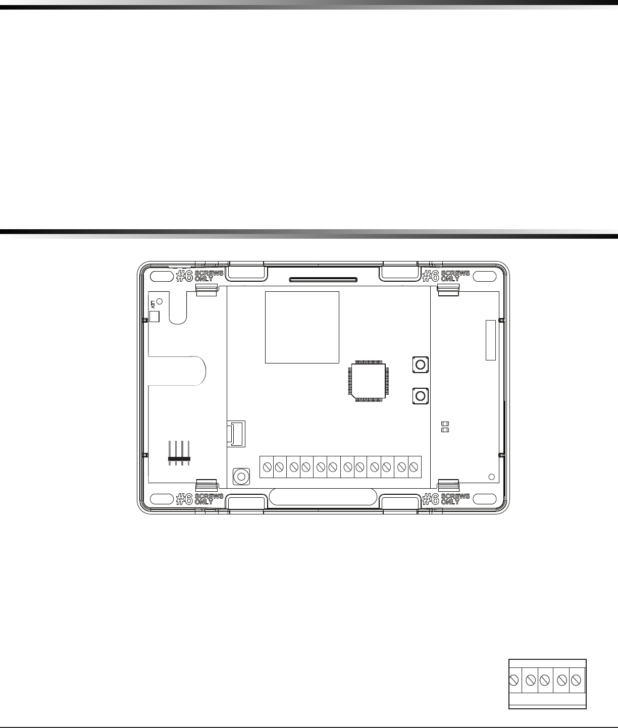
System Components
1.1 Terminals (J9)
Power Connection Terminals
Powerisprovidedfromthe12VDCauxiliaryoutputoftheburglarycontrolpanel.
OBSERVEPOLARITY(SeeFigure1)
1. Using18-22AWGwire,connectthe
communicator
terminal+12tothepositiveterminalonthe
control
panel auxiliary output
.
2. ConnectthecommunicatorterminalG(Ground)tothenegativeterminalonthecontrolpanelauxiliary
output.
Standby Battery
Duringapoweroutage,theCellComSLdrawspowerfromtheburglarycontrolpanel’sbackup
battery.TheCellComSLmustbeincludedinthestandbybatterycalculationsfortheburglary
control panel.
Zones 1-3
TerminalsZ1toZ3andG(Ground)providethreezonestoconnecttoindividualoutputsonthe
burglary control panel or to intrusion devices (PIR, door, panic buttons or windows contacts).
Figure 1: CellComSL Series Communicator
RESET
LOAD
BAT
MODEL CellComSL
PROG
S
N
+12 G Z1 Z2 Z4-Z4+GZ3 RTO2O1
RB
J8
J26
J9
S1
S2
S3
SYSTEM COMPONENTS
RESET
LOAD
BAT
MODEL CellComSL
PROG
S
N
+12
G Z1 Z2
Z4-Z4+
GZ3
RTO2O1
RB
J8
J26
J9
S1
S2
S3
Figure 2: Zones 1 - 3
Digital Monitoring Products
CellComSL
Series Communicator Install/Programming Guide
2
SYSTEM COMPONENTS
Zone 4
Zone4(Z4+andZ4-)isintendedforconnectiontothecontrolpanelbelloutput.Thiszonedetectsanalarm
condition on the burglary control panel by monitoring the voltage of the bell output. To enable alarm detection
operation,Zone4mustbeprogrammedasAUX2intheCellComSLprogramming.CellComSLSeriesCommunicator
mustperceivethecadenceforatleastfor3.5seconds.
ThetypeofCadencesenttotheCellComSLCommunicatorandthetypeofmessagetheCellComSLwillsendto
CentralStationarelistedbelow:
Cadence Type of Message
Steady Burglary
T3 CO
T4 Fire
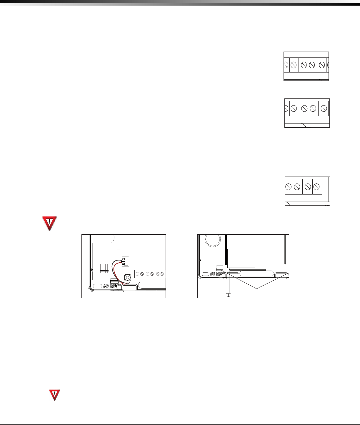
Open-Collector Outputs
Thetwooutputs,terminalsO1andO2(seeFigure4),canbeprogrammedtoindicatethe
activityofthezonesorconditionsoccurringonthesystem.Open-Collectoroutputsdonot
provide a voltage but instead switch-to-ground voltage from another source. The outputs can
respond to any of the conditions listed below:
1) Activationbyzonecondition:Steady,Pulse,Momentary,orFollow
2) Communication
3) Armedareaannunciation
4) ExitandEntrytimers
5) SystemReady
6) LatetoClose
Dialer Connection
Usethetwomiddlewiresfromthetelephonecordconnectedtotheburglarycontrolpaneland
inserteachintoterminalR(Ring)andT(Tip)(SeeFigure5).CAUTION-Toreducetheriskof
re,useonlyNo.26AWGorlargertelecommunicationlinecord.
1.2 Battery Connection (BAT J26)
Installation Safety
Ground Yourself Before Handling the Communicator! To discharge static, touch any grounded metal, such
as the control panel enclosure, before touching the communicator.
System Battery
Ifthesystembatteryislow,ornotpluggedintotheBATbatteryconnector,alowbatteryconditionisindicatedby
the
communicator
.
PluginthesystembatteryintheBATconnector(J26).
DMPrecommendsreplacingthebatteryevery3yearsundernormaluse.
Usethefollowingstepstoreplacethesystembattery.
1. UnplugthebatteryBATconnector(J26)fromthecommunicator.
2. LoosenthetopPCBsnaps.
3. Leanthe
communicator
PCB forward and lift out from the bottom PCB snaps.
4. Remove and properly dispose of the used battery.
Caution:Riskofre,explosion,andburns.Donotdisassemble,heatabove212°F(100°C),orincinerate.
Properly dispose of used batteries.
5. Place the new battery into the housing base with the battery wires directed toward the bottom left corner.
SeeFigure6.
6. SetthePCBintothebottomsnapsandpressintothetopsnapstosecureinplace.
Top PCB Snaps
Bottom PCB Snaps
Battery
connector
3.7 VDC
800 mAH Lithium
Ion Battery
Figure 6: Replacement Battery Locations
RESET
LOAD
BAT
MODEL CellComSL
PROG
S
N
+12 G Z1 Z2
Z4-Z4+G
Z3 RTO2
O1
RB
J8
J26
J9
S1
S2
S3
Figure 3: Zone 4
RESET
LOAD
BAT
MODEL CellComSL
PROG
S
N
+12 G Z1 Z2 Z4-Z4+GZ3 RTO2O1
RB
J8
J26
J9
S1
S2
S3
Figure 4: Outputs 1 and 2
RESET
LOAD
BAT
MODEL CellComSL
PROG
S
N
+12 G Z1 Z2 Z4-Z4+GZ3 RTO2O1
RB
J8
J26
J9
S1
S2
S3
Figure 5: Terminals T and R
RESET
LOAD
BAT
MODEL CellComSL
PROG
S
N
+12 G Z1 Z2
Z4-Z4+
GZ3
RTO2O1
RB
J8
J26
J9
S1
S2
S3
SYSTEM COMPONENTS
CellComSL
Series Communicator Install/Programming Guide Digital Monitoring Products
3
7. Plug the battery into the
BAT
connector(J26).
Note:Ifremovingthecommunicatorfromservice,disconnectthesystembatteryfromtheBATconnector(J26).
Battery Supervision
ThecommunicatorteststhebatteryonceeveryhourwhenDCpowerispresent.Thistestoccurs15minutespast
eachhourandlastsforveseconds.Aloadisplacedonthebatteryandifthebatteryvoltageislow,alowbattery
isdetected.IfDCpowerhasfailed,alowbatteryisdetectedanytimethebatteryvoltagefallsbelow3.7VDC.
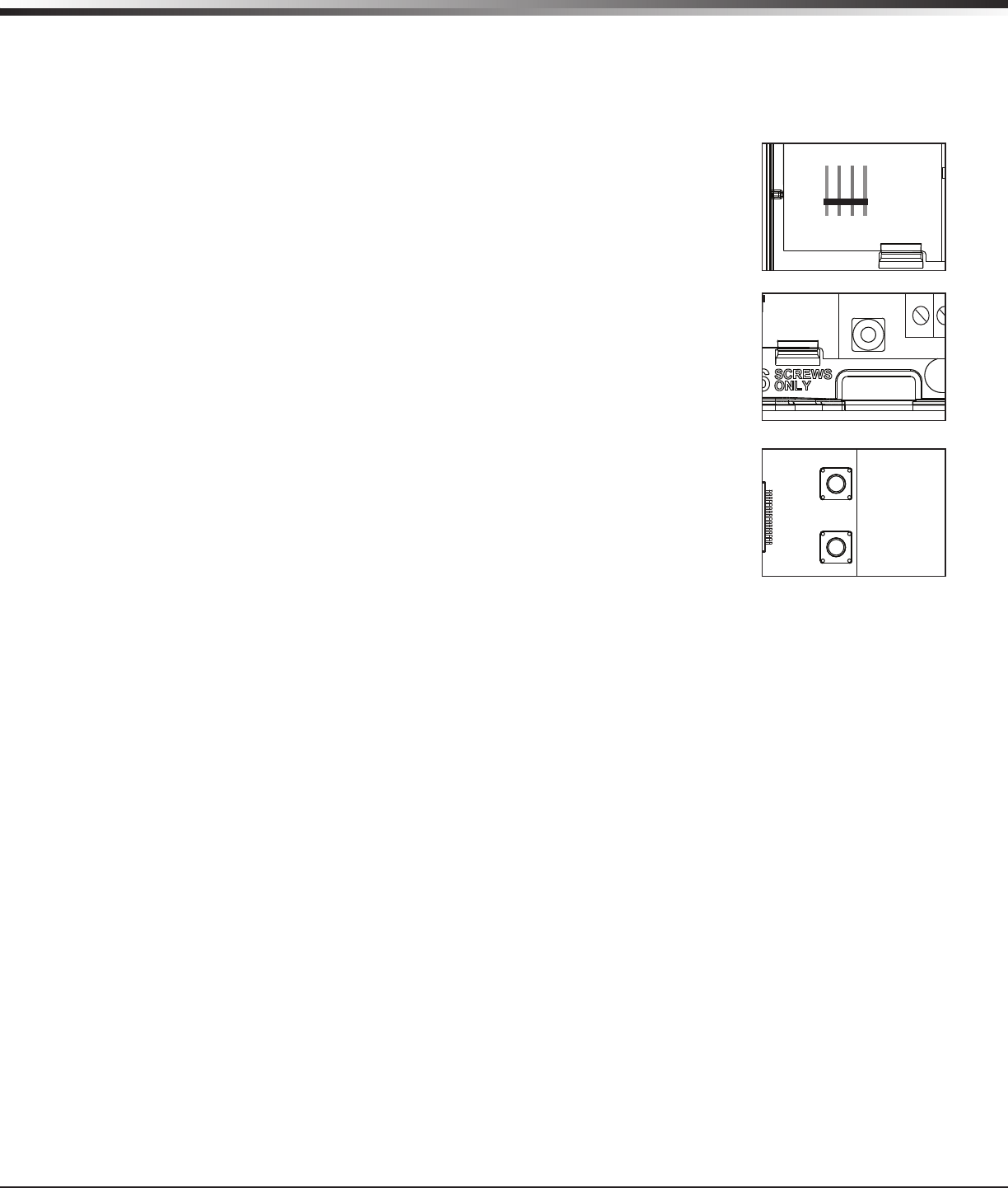
1.3 Programming Connection (PROG J8)
A4-pinheader(PROG)isprovidedtoconnectakeypadwhenusingaDMPModel330
ProgrammingCable.Thisprovidesaquickandeasyconnectionforprogrammingthe
CellComSL
SeriesCellularAlarmCommunicator.Afterprogrammingiscomplete,remove
thekeypad.
1.4 Tamper (C3)
ThetamperbuttonispressedwhenthecoveroftheCellComSLSeries
Communicatorissecuredontotheenclosure.Whenthecoverisremoved,the
communicatorsendsaTamperTroublemessagetotheCentralStation.
1.5 Reset Button
TheResetbutton(S1)islocatedontherightsideofthecircuitboardandisused
toresetthecommunicatormicroprocessor.Afterresettingthe
communicator,
begin
programmingwithin30minutes.Ifyouwaitlongerthan30minutes,resetthe
communicator
again.
1.6 Load Button
The
CellComSL
SeriesCellularAlarmCommunicatorsoftwarecanbeupdated
viatheprogramming(PROG)header.Toupdatethecommunicatorwithanewsoftware
version, complete the following steps at the protected premise:
1. ConnectaDMP399CablefromtheProgrammingHeadertotheserialportofyour
PCoperatingRemoteLinkandcontainingthecommunicatorRUle.
2. StartRemoteLinkandcreateoropentheaccountthatmatchesthecommunicator
to be updated.
3. SettheConnectionInformationTypetoDirectwithabaudrateof38400and
choosetheappropriateCOMport.
4. SelectPanel>RemoteUpdate,thenselectthecorrectRUleforthe
communicator.
5. PressandholdtheLOADbutton(S2),thenpressandreleasetheRESETbutton.
6. ReleasetheLOADbuttonandclick<Update>inRemoteLink.
7. Afterthesoftwareupdateiscompleted,removethe399cableandpresstheRESETbuttontoresumenormal
operation.
Figure 5: Terminals T and R
RESET
LOAD
BAT
MODEL CellComSL
PROG
S
N
+12 G Z1 Z2 Z4-Z4+GZ3 RTO2O1
RB
J8
J26
J9
S1
S2
S3
Figure 7: PROG Port Location
RESET
LOAD
BAT
MODEL CellComSL
PROG
S
N
+12
G Z1 Z2 Z4-Z4+GZ3 RTO2O1
R
B
J8
J26
J9
S1
S2
S3
Figure 8: Tamper (S3) Location
RESET
LOAD
BAT
MODEL CellComSL
PROG
S
N
+12 G Z1 Z2 Z4-Z4+GZ3 RTO2O1
RB
J8
J26
J9
S1
S2
S3
Figure 9: Reset (S1) and
Load (S2) Button Location
Digital Monitoring Products
CellComSL
Series Communicator Install/Programming Guide
4
INSTALLATION
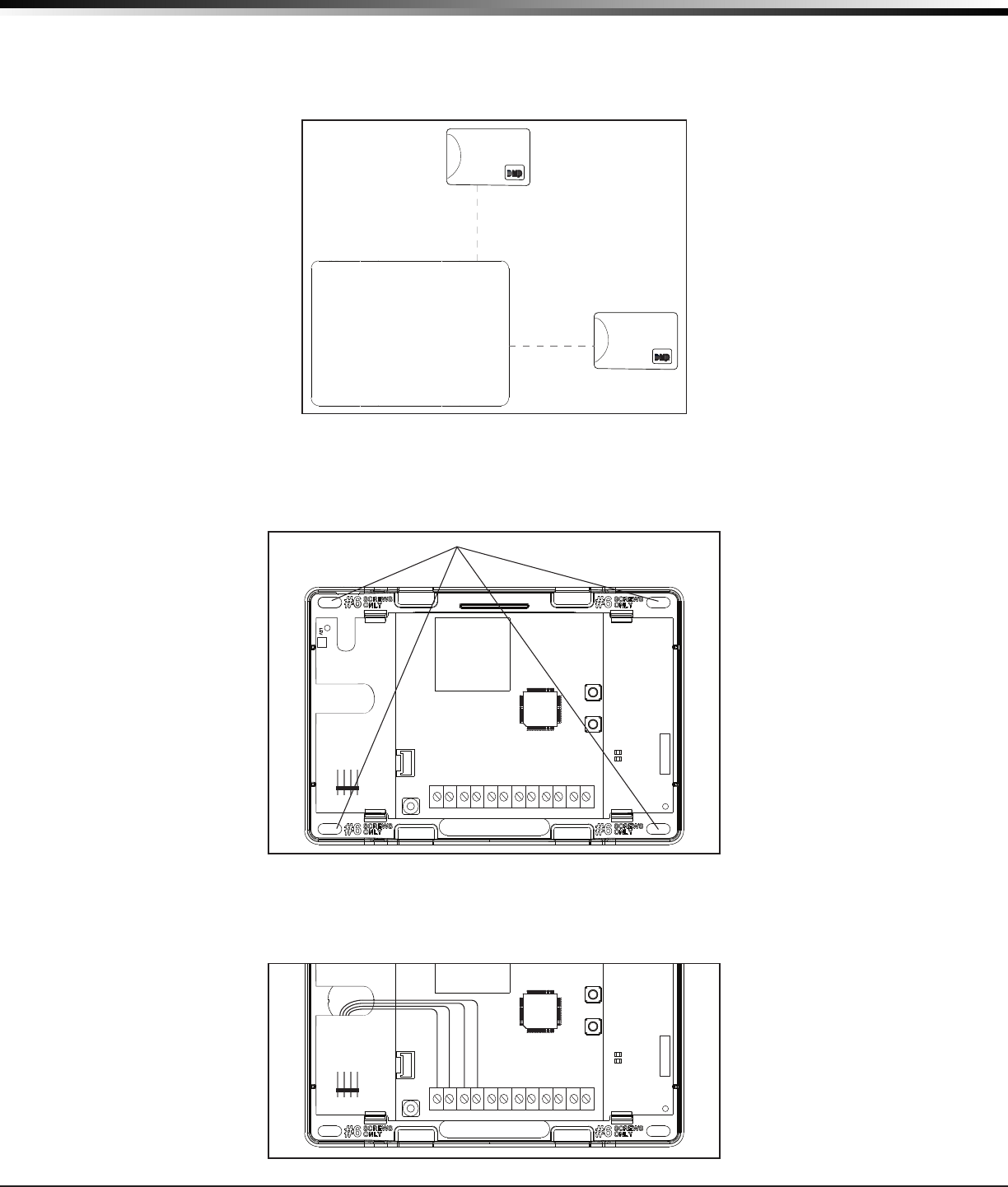
Mounting the CellComSL Series Communicator
2.1 Selecting a Location
Install the communicator away from metal objects. DO NOTmounttheCellComSLSeriesCommunicatorinsideor
ontheburglarycontrolpanelmetalenclosure(SeeFigure10).
Mountingthecommunicatoronornearmetalsurfacesimpairsperformance.Theenclosureforthe
c
ommunicator
mustbemountedusingtheprovided#6screwsinthefourmountingholes(SeeFigure11).Mounttheenclosurein
a secure, dry place away from metal objects to protect the communicator from damage due to tampering or the
elements. It is not necessary to remove the PCB when installing the enclosure.
Burglary Control
Panel
Metal Enclosure
Figure 11: Mounting Screw Locations
RESET
S1
LOAD
S2
BAT
MODEL CellComSL
PROG
S
N
+12 G Z1 Z2 Z4-Z4+GZ3 RTO2O1
RB
Mounting Screw Locations
Figure 10: Suggested Mounting Locations
Figure 12: Wire Routing
RESET
S1
LOAD
S2
BAT
MODEL CellComSL
PROG
S
N
+12 G Z1 Z2 Z4-Z4+GZ3 RTO2O1
RB
Wheninstallingcomponentwirescaremustbetakentorouteallwiresinsuchamannerthattheywillnot
interferewiththeTamperswitch.SeeFigure12.
CellComSL
Series Communicator Install/Programming Guide Digital Monitoring Products
5
APPLICATIONS
Applications
TheCellComSLSeriesCommunicatorisusedinonlyoneofthethreeapplications:
3.1
Dialer Connection
ConnectthetwomiddlewiresofthephonelinefromthecontrolpanelandconnecttotheCellComSLSeries
CellularCommunicatortocaptureContactIDmessagesfromtheburglarycontrolpanelandsendthemessagetoa
DMPModelSCS-1RorSCS-VRReceiver.OnlyOutputscanbeusedincombinationwiththisapplication(SeeFigure
13).
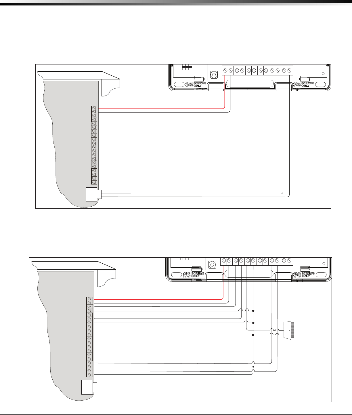
3.2 Zones 1 - 3 and Outputs
Wiredintrusiondevicessuchasdoorcontacts,tamperswitches,panicbuttonsandPIRscanbewiredtoZ1through
Z3forzonesensingsupervision.ConnectwiresfromtheCellComSLOutputs(O1andO2)totheburglarycontrol
panelzones.(See1.1Terminals>ZonesformoreinformationandFigure14forwiringdetails).
Use 18-22 AWG for
Power Supply connection
Z3 +
Z4 +
Z4 -
GND
OUT1
OUT2
CONTROL PANEL TIP
CONTROL PANEL RING
12 VDC Aux. Output +
-
Ground
Burglary Panel
The panel or separate power
supply must be 12 Volt Regulated
and Power Limited.
Telephone
Jack
Connector
Z1 +
Z2 +
BELL -
BELL +
Input Zone 2 +
Input Zone 2 -
Input Zone 1 +
Input Zone 1 -
RESET
S1
LOAD
S2
BAT
MODEL CellCom
PROG
S
N
+12 G Z1 Z2 Z4-Z4+GZ3 RTO2O1
RB
†
{
Normally Open
Common
Normally Closed
Normally Open
Common
Normally Closed
†
{
Normally Open
Common
Normally Closed
†
{
J8
J26
J9
S1
S2
S3
Figure 13: CellComSL Series Wiring Diagram for Tip and Ring Connection
Use 18-22 AWG for
Power Supply connection
Z3 +
Z4 +
Z4 -
GND
OUT1
OUT2
CONTROL PANEL TIP
CONTROL PANEL RING
12 VDC Aux. Output +
-
Ground
Burglary Panel
The panel or separate power
supply must be 12 Volt Regulated
and Power Limited.
Telephone
Jack
Connector
Z1 +
Z2 +
BELL -
BELL +
Input Zone 2 +
Input Zone 2 -
Input Zone 1 +
Input Zone 1 -
RESET
S1
LOAD
S2
BAT
MODEL CellCom
PROG
S
N
+12 G Z1 Z2 Z4-Z4+GZ3 RTO2O1
RB
†
{
Normally Open
Common
Normally Closed
Normally Open
Common
Normally Closed
†
{
Normally Open
Common
Normally Closed
†
{
J8
J26
J9
S1
S2
S3
Wired Door
Contact
Figure 14: CellComSL Series Wiring Diagram for Zones 1 - 3 and Outputs.
Digital Monitoring Products
CellComSL
Series Communicator Install/Programming Guide
6
APPLICATIONS
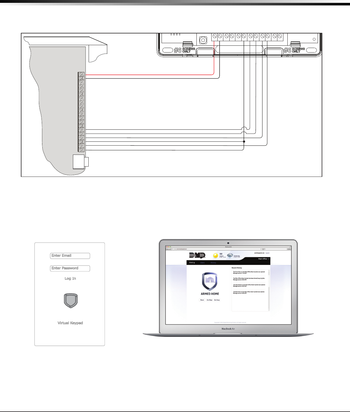
3.3 Zone 4 and Outputs
Zone4(Z4+andZ4-)isintendedforconnectiontothecontrolpanelbelloutput.Thiszonedetectsanalarm
conditionontheburglarycontrolpanelbymonitoringthevoltageofthebelloutput.(See1.1Terminals>Zone4
for more information and Figure 15 for wiring details).
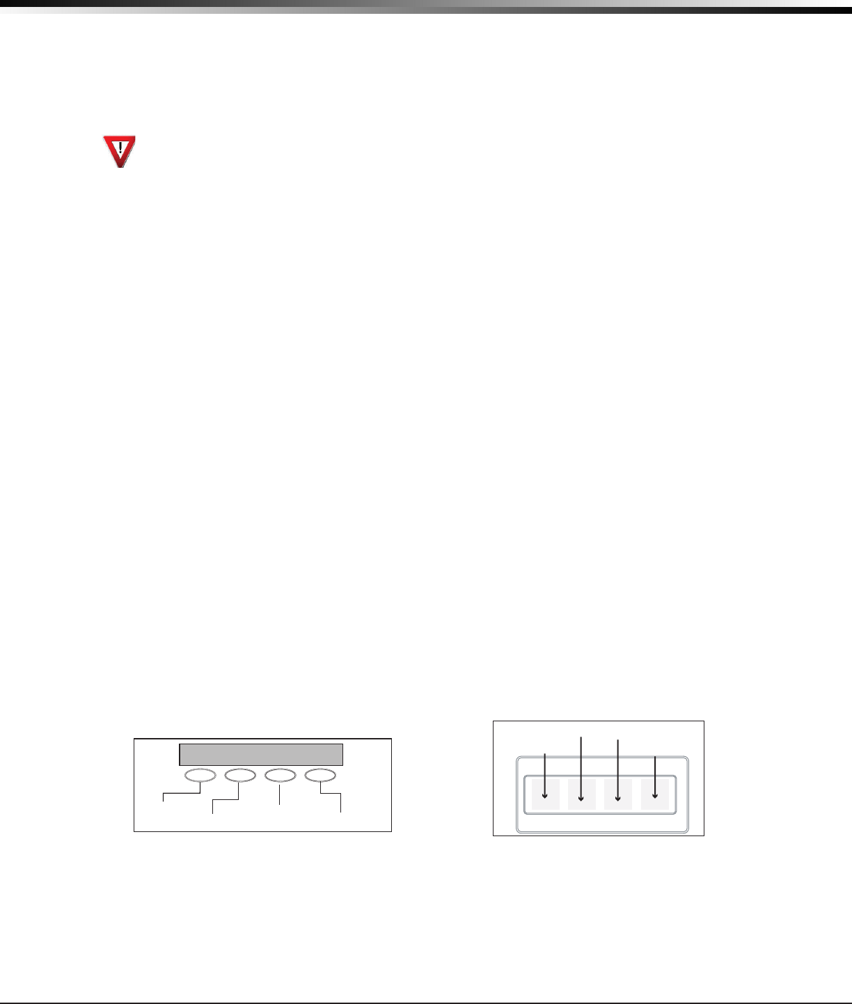
3.4 Virtual Keypad App
UsingyourSmartphoneandtheDMPVirtualKeypadApp,youcanconnecttoyourCellComSLSeriesCommunicator
toarmtheArea,congureZ-Wavedevices(CellComSLCZonly),congureyourFavorites(CellComSLCZonly),
congureRooms(CellComSLCZonly),turnOutputsonandoff,andadd,editorremoveUsers.
Use 18-22 AWG for
Power Supply connection
Z3 +
Z4 +
Z4 -
GND
OUT1
OUT2
CONTROL PANEL TIP
CONTROL PANEL RING
12 VDC Aux. Output +
-
Ground
Burglary Panel
The panel or separate power
supply must be 12 Volt Regulated
and Power Limited.
Telephone
Jack
Connector
Z1 +
Z2 +
BELL -
BELL +
Input Zone 2 +
Input Zone 2 -
Input Zone 1 +
Input Zone 1 -
RESET
S1
LOAD
S2
BAT
MODEL CellCom
PROG
S
N
+12 G Z1 Z2 Z4-Z4+GZ3 RTO2O1
RB
†
{
Normally Open
Common
Normally Closed
Normally Open
Common
Normally Closed
†
{
Normally Open
Common
Normally Closed
†
{
J8
J26
J9
S1
S2
S3
Figure 15: Zone 4 and Output Connections
Enter Email
Enter Password
Log In
Virtual Keypad
Figure 16: Virtual Keypad Application can be used to access the CellComSL Series Communicator.

CellComSL
Series Communicator Install/Programming Guide Digital Monitoring Products
7
Z-WAVE SETUP
Z-Wave Setup
(Model CellComSLCZ Only)
User Code Level: Master only.
(AccessedthroughtheUserMenutoprogramyourZ-WaveDevices,UserCodes,etc.)Yoursystemmayincludea
DMPZ-Wavecontroller.TheZ-WavecontrollerallowsshortrangeradiocontrolofZ-Wavedevicesthatyouoryour
installationcompanymayprovidesuchaslightingcontrolmodules,thermostatcontrols,anddoorlocks.Z-Wave
SetupallowsyoutoprogramthesystemtocontroltheZ-Wavedevices.YoumaycontrolyourZ-Wavedevices
fromyouriPhone/iPadorAndroiddeviceusingtheDMPVirtualKeypadApporfromyourkeypadbyactivatinga
FavoritefromtheFavoritesUserMenu.Theavailablesetupoptionsare:Add,List,Remove,Favorites,Transferand
Rediscover.
• SelectADDtoaddaZ-Wavedevicetoyoursystem.
• SelectLISTtodisplayalistofZ-Wavedevicesalreadyaddedandstoredinyoursystem.
• SelectREMOVEtocompletelyremoveaZ-Wavedevicefromyoursystem.
• SelectFAVtoAdd,EditorRemoveaFavorite.
• SelectXFERtotransferZ-Wavedeviceinformationfromanothermanufacturer’sportableZ-Wavecontroller
to your system.
• SelectREDISCtorequireyoursystemtorediscoverandconrmradiocommunicationwithalloftheadded
Z-Wavedevices.
5.1 Add Z-Wave Devices (ADD)
ThisoptionallowsyoutoADDaZ-Wavedevicetoyoursystem.Onceadded,aZ-Wavedevicemaybeassignedtoa
Favorite.
1. AccesstheUserMenu.
2. Press COMMANDuntilZWAVESETUP?displays.
3. PressanySelectkey.ThekeypaddisplaysADDLISTREMOVE.
4. SelectADD.PROCESSINGmaybrieydisplay.WhenPRESSBUTTONONDEVICETOADDdisplayspressthe
program button on the Z-Wavedevice.SeetheZ-Wavedevice’sdocumentationformoreinformation.
5. Whenthedeviceinformationisreceivedbythesystem,thekeypadbeepsonceanddisplaysDEVICEFOUND.
6. Onceadded,thekeypaddisplaysthetypeofdeviceandthedefaultdevicename.PressCOMMAND.
7. PressanytoprowSelectkeyandenteruptoa16charactercustomnameforthedevice.SeeEnteringNames
inAppendixD.
8. Press the COMMANDkeytostorethenewname.
Note:Amaximumof232Z-Wavedevicescanbeaddedtothesystem.Whenthemaximumnumberofdeviceshavebeen
added,thekeypaddisplaysZWAVETABLEFULLandnoadditionalZ-Wavedevicesmaybeaddedwithoutremoving
some existing devices.
5.2 List Z-Wave Devices (LIST)
ThisoptionallowsyoutoeditthenameofaZ-WavedeviceorconrmradiocommunicationwiththeZ-Wave
device.WhenLISTisselected,therstZ-Wavedevicestoredinthesystemisdisplayed.Remainingdevicescan
be viewed by pressing the COMMANDkey.Lightingcontrolmodules,aredisplayedrst,followedbydoorlocksand
then thermostat controls.
TheavailableLISToptionsare:RenameandStatus.
• SelectRENAMEtoenterupto16charactersforanewdevicename.
• SelectSTATUStoconrmradiocommunicationwiththeZ-Wavedevice.
5.3 RENAME Z-Wave Devices
1. AccesstheUserMenu.
2. Press COMMANDuntilZWAVESETUP?displays.
3. PressanySelectkey.ThekeypaddisplaysADDLISTREMOVE.
4. SelectLISTtodisplayDEVICELISTandtherstZ-Wavedevicestored.PresstheCOMMANDkeytoadvance
through the list of Z-Wavedevices.
5. PressanySelectkeytodisplayDEVICERENAMESTATUS.
6. SelectRENAMEandenterupto16charactersforanewdevicename.SeeEnteringNamesinAppendixD.
7. Press COMMANDtosavethenewZ-WavedevicenameandreturntotheDEVICELIST.

Digital Monitoring Products
CellComSL
Series Communicator Install/Programming Guide
8
Z-WAVE SETUP
5.4 STATUS of Z-Wave Devices
1. AccesstheUserMenu.
2. Press COMMANDuntilZWAVESETUP?displays.
3. PressanySelectkey.ThekeypaddisplaysADDLISTREMOVE.
4. SelectLISTtodisplayDEVICELISTandtherstZ-Wavedevicestored.PresstheCOMMANDkeytoadvance
through the list of Z-Wavedevices.
5. PressanySelectkeytodisplayDEVICERENAMESTATUS.
6. SelectSTATUStoconrmradiocommunicationwiththeZ-Wavedevice.
7. ThedevicenameandOKAYdisplayswhenthedevicestoredinthesystemcommunicates.
8. Press the COMMANDkeytoreturntothedevicelistanddisplaythenextdeviceinthelist.
9. Ifthedevicestoredinthesystemdoesnotcommunicate,thedevicenameandFAILEDdisplays.Pressthe
COMMANDkeyandREMOVEFAILEDDEVICEdisplays.
10. SelectYEStoremovethefaileddevicefromthesystemmemory.SelectNOtoleavethedeviceinthesystem
memory and to return to the device list.
11. Whenthedevicehasbeenremoved,thedevicenameandREMOVEDisdisplayedandthesystemnolongertries
to communicate with the Z-Wavedevice.
5.5 Remove Z-Wave Devices (REMOVE)
EachZ-Wavedeviceaddedtoyoursystemremainsinyoursystemunlessitisremoved.Thisoptionallowsyouto
remove Z-Wavedevicesfromyoursystem.
1. AccesstheUserMenu.
2. Press COMMANDuntilZWAVESETUP?displays.
3. PressanySelectkey.ThekeypaddisplaysADDLISTREMOVE.
4. SelectREMOVE.PROCESSINGmaybrieydisplay.WhenPRESSBUTTONONDEVICETOREMOVEdisplayspress
the program button on the Z-Wavedevice,thedevicenameandREMOVEDisdisplayedtoindicatetheZ-Wave
device has been removed.
5.6 Favorites (FAV)
Z-WavedevicescanbegroupedtogethertocreateaFavorite.Thisoptionallowsyoutoprogramupto20Favorites
inyoursystemandthenADD,EDITORREMOVEupto25Z-WavedevicesinaFavorite.Whenactivatedfromthe
FAVORITEusermenu,acommandissenttoitsZ-WaveDevices.AFavoritecanonlybeactivated,orturnedon.
AseparateFavoritemustbecreatedtochangetheconditionssetbytherstFavorite.Forexample,aFavorite
called“MovieNight”couldlocktheexteriordoors,closethegaragedoor,adjustthetemperature,anddimthe
lightsinthefamilyroomtothedesiredlevel.AnotherFavoritecalled“Wakeup”couldthenturnonthelights,
adjustthetemperature,unlocktheexteriordoors,andraisethegaragedoors.
5.7 Adding a FAVORITE
1. AccesstheUserMenu.
2. Press COMMANDuntilZWAVESETUP?displays.
3. PressanySelectkey.ThekeypaddisplaysADDLISTREMOVE.
4. Press COMMANDagaintodisplayFAVXFERREDISC.SelectFAVandFAVORITENUMBER:-isdisplayed.
5. EnteraFavoritenumberbetween1and20andpressCOMMAND.IftheFavorite number entered is unassigned,
*UNUSED*displays.IftheFavoriteisalreadyassigned,youmaychangethenameorpressthebackarrowand
enter a new number.
6. PressanySelectkeyandacursordisplays.EnteraFavorite name up to 16 characters. To remove a Favorite,
press Command without entering a name.
7. Press COMMANDtosavetheFavorite and the FavoritenameandADDEDITREMOVEdisplays.
5.8 ADD Devices to FAVORITES
1. AccesstheUserMenu.
2. Press COMMANDuntilZWAVESETUP?displays.
3. PressanySelectkey.ThekeypaddisplaysADDLISTREMOVE.
4. Press COMMANDagaintodisplayFAVXFERREDISC.SelectFAVandFAVORITENUMBER:-isdisplayed.
5. EnteraFavoritenumberbetween1and20andpressCOMMAND.
6. The Favorite number and name displays. Press COMMANDandtheFavoriteNameandADDEDITREMOVE
displays.

CellComSL
Series Communicator Install/Programming Guide Digital Monitoring Products
9
Z-WAVE SETUP
7. SelectADDandtherstZ-WavedevicestoredinthesystemthathasnotalreadybeenaddedtothisFavorite is
displayed. Remaining devices can be viewed by pressing the COMMANDkey.
8. PressanySelectkeytoassignthedisplayeddevicetotheFavorite. The device name and the current device
settingsdisplay.WhenaddedtoaFavorite,aZ-WavedevicecanbeprogrammedtorespondtovariousON/
OFF/LOCK/UNLOCK/HEAT/COOLcommandsbasedonyourdesiredsettings.Tochangeadevicesetting,See
DeviceSettingsinFavorites.
5.9 Device Settings in FAVORITES
Lights
1. PressanySelectkeyatSETTING:andONOFFDIMdisplays.PresstheSelectkeyunderthedesiredsetting.
2. ForONorOFFsetting,whenselected,theFavorite name and the next Z-Wavedevicestoredinthesystem
displays.
3. ForDIMsetting,DIMLEVEL:withthecurrentsettingdisplays.Tochangethesetting,pressanySelectkeyand
enterthenewlevel(1-10)andPressCOMMAND.
4. The Favorite name and the next Z-Wavedevicestoredinthesystemdisplays.
Locks
1. PressanySelectkeyatSETTING:andLOCKUNLOCKdisplays.To changethesetting,presstheSelect
keyunderthenewsetting.
2. The Favorite name and the next Z-Wavedevicestoredinthesystemdisplays.
Thermostats
1. PressanySelectkeyatSYSTEM:andOFFCLHTdisplays.TochangethesettingofOFF,COOLorHEAT,press
theSelectkeyunderthenewsetting.
2. SelectOFFtodisplayFANSETTING:.
3. PressanySelectkeyandONAUTOdisplays.PresstheSelectkeyunderthedesirednewsettingtochange.
4. SelectCLtodisplayCOOL.
5. Tochangethesetting,pressanySelectkey,enterthenewtemperatureandpressCOMMAND.
6. PressanySelectkeyandthekeypaddisplays
FANSETTING:.
7. PressanySelectkeyandONAUTOdisplays.PresstheSelectkeyunderthedesirednewsettingtochange.
8. SelectHTtodisplayHEAT.
9. Tochangethesetting,pressanySelectkeyandenterthenewtemperatureandPressCOMMAND.
10. PressanySelectkeyandthekeypaddisplays
FANSETTING:.
11. PressanySelectkeyandONAUTOdisplays.PresstheSelectkeyunderthedesirednewsettingtochange.
12. The Favorite name and the next Z-Wavedevicestoredinthesystemdisplays.
Note:Amaximumof25devicescanbeassignedtoeachFavorite.Whenattemptingtoaddadeviceandthe
maximumnumberofdeviceshasbeenassigned,FAVORITEFULLisdisplayed.NoadditionalZ-Wavedevices
may be added to this Favorite, however a new Favorite may be created and devices added to the new
Favorite.
5.10 EDIT Devices in FAVORITES
1. AccesstheUserMenu.
2. Press COMMANDuntilZWAVESETUP?displays.
3. PressanySelectkey.ThekeypaddisplaysADDLISTREMOVE.
4. Press COMMANDagaintodisplayFAVXFERREDISC.SelectFAVandFAVORITENUMBER:-isdisplayed.
5. EnteraFavoritenumberbetween1and20andpressCOMMAND.
6. The Favorite number and name displays. Press COMMANDandtheFavoriteNameandADDEDITREMOVE
displays.
7. SelectEDITandtherstZ-WavedevicestoredintheFavorite displays. Remaining devices can be viewed by
pressing the COMMANDkey.
Note: Z-Wavedevicesaredisplayedbydevicetype;Lightsrst,followedLocks,andThermostatslast.Bypressing
the COMMANDkeyyoucanscrollthroughthedevicesassignedtotheselectedFavorite.
8. PressanySelectkeytodisplaythedevicenameandthesettingforthedevice.
9. Tochangethesetting,SeeDeviceSettingsinFavorites.
10. Oncethedevicesettingshavebeenentered,theFavorite name and the next Z-Wavedevicestoredinthe
selected Favorite displays.

Digital Monitoring Products
CellComSL
Series Communicator Install/Programming Guide
10
Z-WAVE SETUP
5.11 REMOVE Devices from FAVORITES
1. AccesstheUserMenu.
2. Press COMMANDuntilZWAVESETUP?displays.
3. PressanySelectkey.ThekeypaddisplaysADDLISTREMOVE.
4. Press COMMANDagaintodisplayFAVXFERREDISC.SelectFAVandFAVORITENUMBER:-isdisplayed.
5. EnteraFavoritenumberbetween1and20,pressCOMMAND.
6. The Favorite number and name displays. Press COMMANDandtheFavoriteNameandADDEDITREMOVE
displays.
7. SelectREMOVEandtherstZ-WavedevicestoredintheFavorite displays. Remaining devices can be viewed
by pressing the COMMANDkey.
8. PressanySelectkeytoremovethedevicefromtheFavorite.REMOVEDEVICEFROMFAV?NOYESdisplays.
WhenYESisselected,thedeviceisremovedfromtheFavorite.
5.12 Transfer Controller (XFER)
This option allows the transfer of all existing Z-Wavedevicesthatarecurrentlyprogrammedinanother
manufacturer’sZ-Waveportablecontrollertoyoursystem.
This operation will overwrite all Z-Wavedevicesthatareprogrammedinyoursystem.Thisoptiontypically
occursatthetimeyourDMPZ-Wavecontrollerisinstalled.
Initiatethetransferattheothermanufacturer’sZ-Waveportablecontrollerafterstartingthetransfer
ontheDMPkeypad.Z-WavedevicesareNOToverwrittenuntilthetransferhasbeeninitiatedattheother
manufacturer’sZ-Waveportablecontroller.Thetransfershouldnotbestoppedoncetheprocesshasbeeninitiated
fromtheothermanufacturer’sZ-Waveportablecontroller.
Transfer Operation:
1. AccesstheUserMenu.
2. Press COMMANDuntilZWAVESETUP?displays.
3. PressanySelectkey.Thekeypaddisplays
ADDLISTREMOVE.
4. Press COMMANDagaintodisplayFAVXFERREDISC.SelectXFER.ThekeypaddisplaysXFERWILLDELETE
EXISTINGDEVICESthendisplaysXFERCNTRLSURE?YESNO.
5. SelectYEStotoallowreceiptofZ-Wavedevicestoyoursystem.ThekeypaddisplaysTRANSFERRINGZ-WAVE
DEVICES.PressingtheBackArrowkeycancelsthetransfer.SelectNOtoexittheXFERmenuandreturnto
ZWAVESETUP?.AllprogrammingwillstillbeintactontheDMPZ-Wavecontrollerandwillcancelthetransfer.
6. Initiate the transfer at the othermanufacturer’sZ-Waveportablecontroller.AllZ-Wavedevicesareadded
tothesystemwithadefaultname(devicetypeandnumber).A16-characternamemaybeassignedtothe
Z-Wavedevicesafterthetransferiscomplete.WhenthetransferiscompletethescreenwilldisplayZWAVE
SETUP?.
Note:IfTRANSMISSIONFAILEDdisplaysonthescreen,yoursystemmemoryisclearedofallpriorZ-Wavedevices
programmingandwillneedtoaddeachZ-Wavedeviceindividually.
5.13 Rediscover (REDISC)
This option allows your system to search for and re-establish communication with Z-Wavedevicesthatmayhave
failedtocommunicate.OnlyZ-Wavedevicesalreadyprogrammedintoyoursystemareincludedintherediscovery
search.AnyprogrammedZ-Wavedevicethatisnotfoundduringrediscoverywillbedeletedfromyoursystem.
1. AccesstheUserMenu.
2. Press COMMANDuntilZWAVESETUP?displays.
3. PressanySelectkey.ThekeypaddisplaysADDLISTREMOVE.
4. Press COMMANDagaintodisplayFAVXFERREDISC.
5. SelectREDISC,thekeypaddisplaysREDISCOVERINGZWAVEDEVICESwhilethesystemissearchingforZ-Wave
devices.
6. Whentherediscoveryiscomplete,thekeypadreturnstoZWAVESETUP?

PROGRAMMING INTRODUCTION
CellComSL
Series Communicator Install/Programming Guide Digital Monitoring Products
11
Programming the
CellComSL
Series Cellular Alarm Communicator
6.1 Before You Begin
Before starting to program, we recommend you read through the contents of this manual. The information in
thisdocumentallowsyoutoquicklylearntheprogrammingoptionsandoperationalcapabilitiesofthe
CellComSL
SeriesCellularAlarmCommunicator.
AfterthisIntroduction,theremainingsectionsdescribethefunctionsofeachprogrammingmenuitemsalongwith
their available options. The
communicator
contains all of its programming information in an on-board processor
and does not require an external programmer.
In addition to this manual, you should also be familiar with the following
documents:
• CellComSL
SeriesCellularAlarmCommunicatorUserSheet
• CellComSL
SeriesCellularAlarmCommunicatorProgrammingSheet
Programming Information Sheet
Included with each communicatoraretheProgrammingSheets.Thesesheetslistthevariousoptionsavailablefor
programming the
communicator
.Beforestarting,completelylloutthesheetswiththeprogrammingoptionsyou
intend to enter into the
communicator
.
Having completed programming sheets available while entering data helps to prevent errors and can shorten
the length of time you spend programming. Completed sheets also provide you with an accurate account of the
communicator
’sprogramyoucankeeponleforfuturesystemserviceorexpansion.
The remainder of the Introduction explains starting and ending a programming session.
6.2 Getting Started
Ground Yourself Before Handling the Panel! Touch any grounded metal before touching the communicator
to discharge static.
Remove All Power From the Panel! RemoveallACandBatterypowerfromthecommunicator before
installing or connecting any wires to the communicator.
The communicatorshouldbecompletelyinstalledbeforeyoubeginprogramming.Makesurethecommunicator is
properlygrounded,andtheACandbatterywiresarecorrectlyinstalled.
Initializing the
CellComSL
Series
Whenprogramminga
communicator
forthersttimeorrewritingtheentireprogramofanexistingcommunicator,
use the Initialization functiondescribedinsection7.Initializingclearsthecommunicator’smemoryofanyold
dataandsetsthehighestnumberedusernumbertousercode99.
Accessing the Programmer
To access the programmer function of the
communicator
:
1. ConnectthekeypadtothePROGheader
2. Press the reset button.
3. Enterthecode6653(PROG).
4. Thekeypaddisplays:PROGRAMMER.
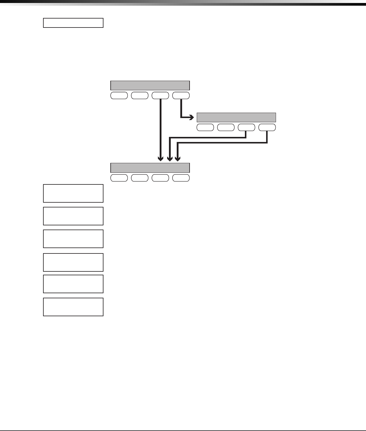
6.3 Programming Menu
Youarenowreadytostartprogrammingthe
CellComSL
SeriesCellularAlarmCommunicator.Pressingthe
COMMANDkeyscrollsyouthroughtheprogrammingmenuitemslistedbelow.
Menu Item Section in This Manual Menu Item Section in This Manual
Initialization 7 Output Options 13
Communication 8 Area Information 14
Messaging Setup 9 Zone Information 15
Remote Options 10 Stop 16
System Reports 11 Set Lockout Code 17
System Options 12
Toselectasectionforprogramming,pressanySelectkey/areawhenthenameofthatsectiondisplaysonthe
keypad.Thedetailedinstructionsforeachprogrammingsteparefoundinthismanual.
Digital Monitoring Products
CellComSL
Series Communicator Install/Programming Guide
12
PROGRAMMING INTRODUCTION
6.4 Reset Timeout
The
CellComSL
SeriesCellularAlarmCommunicatorhasafeaturethatrequiresyoutoentertheProgrammerwithin
30minutesofresettingthecommunicator.After30minutes,ifyouattempttoprogrambyenteringthe6653
(PROG)code,thekeypaddisplays:RESET PANEL.Youmustresetthe
communicator
and enter the program code
withinthenext30minutes.
IfyouarealreadyintheProgrammeranddonotpressanykeysontheprogrammingkeypadfor30minutes,the
communicator
terminatesprogramming.Alldataentereduptothatpointissavedinthecommunicatormemory.
Using the STOP function disarms all areas:Toexitthecommunicator’sProgrammeryoumustusetheSTOP
function. The STOP optionisthesecondtothelastoptioninprogramming.TheStopfunctiondisarmsall
areasandclearsthecommunicator’sStatusList.
TheprogrammingsessionisthenterminatedandthekeypadreturnstotheStatusListorMainScreen.
6.5 Special Keys
Thefollowingspecialkeys/areasarecommontoallDMPkeypads.
COMMAND (CMD) Key
PressingtheCOMMANDkeyallowsyoutogoforwardthroughtheprogrammingmenuandthrougheachstepofa
programmingsection.Asyougothroughtheprogramming,thekeypaddisplayshowsanycurrentprogramming
alreadystoredinthecommunicatormemory.Ifnochangeisrequiredforaprompt,presstheCOMMANDkeyto
advance to the next step.
TheCOMMANDkeyisalsousedtoenterinformationintothecommunicator’smemorysuchasphonenumbersor
zonenames.PresstheCOMMANDkeyafterenteringinformation.
Back Arrow (<—) Key
UsetheBackArrowkeytobackuponestepwhileprogramming.TheBackArrowkeyisalsousedwhenanerroris
madewhileenteringinformation.PresstheBackArrowkeyoncetoerasethelastcharacterentered.
Select Keys/Areas
ThetoprowofkeysarecalledtheSelectkeysonThinline,andAqualitekeypadsorSelectAreasonGraphic
Touchscreenkeypads.EachtimeyouneedtopressaSelectkey,thekeypaddisplaysthefunctionoroptionsabove
oneofthekeysorintheSelectArea.DisplayingchoicesaboveindividualSelectkeysorinSelectAreasallows
themtobeusedformanydifferentapplications.Forexample,youcanenterAMorPMwhenprogrammingthe
automatic test time or answer YES or NO for a system option.
Duringprogramming,theSelectkeys/areasalsoallowyoutochangeinformationcurrentlyincommunicator
memorybypressingtheappropriateSelectkeyunderoronthedisplay.Youthenenterthenewinformationusing
thekeypaddataentrydigitkeys.
Whentherearemorethanfourresponseoptionsavailable,presstheCOMMANDkeytodisplaythenextonetofour
options.PressingtheBackArrowkeyallowsyoutoreviewthepreviousfourchoices.
TheSelectkeys/areasarealsousedforchoosingasectionfromtheprogrammingmenu.PressanySelectkeyor
touchtheSelectAreawhentheprogrammingsectionnameyouwantdisplays.
On Thinline and Aqualite keypads,wheninstructedtopresstherstSelectkey,pressthefarleftSelectkey;the
secondSelectkeyisthesecondfromtheleft;thirdSelectkeyissecondfromtheright;andthefourthSelectkey
isthefarrightkey.SeeFigure17.
On Graphic Touchscreen Keypads,wheninstructedtopresstherstSelectkey,touchSelectArea1;thesecond
SelectkeytouchSelectArea2;thirdSelectkeytouchSelectArea3;andthefourthSelectkeytouchSelectArea4.
SeeFigure18.
6.6 Entering Alpha Characters
Someoptionsduringprogrammingrequireyoutoenteralphacharacters.Toenteranalphacharacter,pressor
touchthekeythathasthatletterwrittenbelowit.Thekeypaddisplaysthenumberdigitofthekey.Next,press
theSelectkey/areathatcorrespondstothelocationoftheletterunderthekey.PressingadifferentSelectkey/
areachangestheletter.Whenanotherdigitkeyispressed,thelastletterdisplayedisretainedandtheprocess
starts over.
Figure 17: Thinline/Aqualite Select Keys Figure 18: Graphic Touchscreen Select Areas
First Letter
Second Letter
Third Letter
Special Character
(CBA
32-Character Display
Select Area 1
Select Area 2 Select Area 3
Select Area 4
CellComSL
Series Communicator Install/Programming Guide Digital Monitoring Products
13
PROGRAMMING INTRODUCTION
6.7 Entering Non-Alpha Characters
Toenteraspaceinanalphaentry,pressthe9digitkeyfollowedbythethirdSelectkey/area.Thethree
charactersonthe9digitkeyareY,Z,andspace.Youcanalsoenterthefollowingcharacters:–(dash),.(period),*
(asterisk),and#(poundsign)usingthe0(zero)keyandthefourSelectkeys/areasfromlefttoright.Forexample,
toentera–(dash),pressthe0(zero)keyandthentheleftSelectkey/area.Adashnowappearsinthekeypad
display.ThetablebelowshowsthecharacterlocationsforDMPkeypads.
Key Number Select Key 1 Select Key 2 Select Key 3 Select Key 4
1 A B C (
2 D E F )
3 G H I !
4 J K L ?
5 M N O /
6 P QR &
7 S T U @
8 V W X ,
9 Y Z space _
0 - . * #
6.8 Keypad Displays Current Programming
Eachprogrammingpromptdisplayedatthekeypadshowsthecurrentlyselectedoptioninthecommunicator
memory.Theseoptionsareeithershownasanumber,ablank,oraNO or YES.Tochangeanumberorblanktoa
newnumber,pressanytoprowSelectkeyortouchanySelectArea.Thecurrentoptionisreplacedwithadash.
Pressthenumber(s)onthekeypadyouwanttoenterasthenewnumberforthatprompt.Itisnotnecessaryto
enternumberswithleadingzeros.Thecommunicatorautomaticallyrightjustiesthenumberwhenyoupressthe
COMMANDkey.
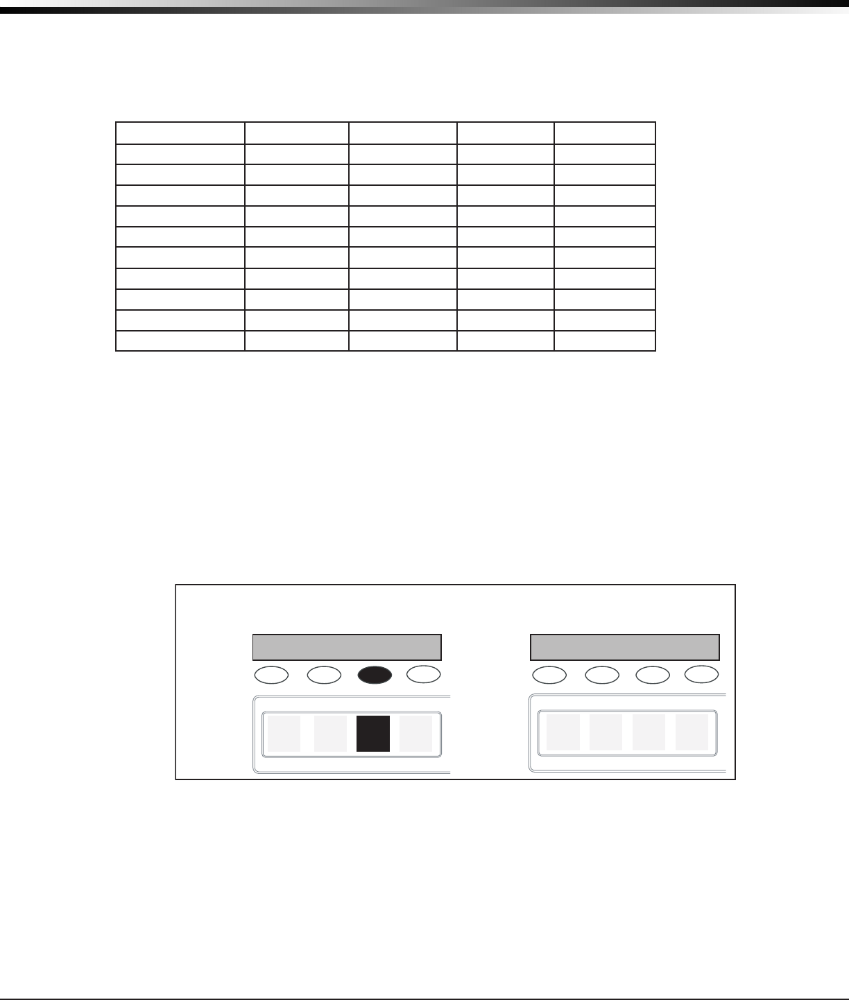
To change a programming prompt that requires a NO or YESresponse,presstheSelectkeyortouchtheSelect
Areafortheresponsenotselected.SeeFigure19.
For example, if the current prompt is selected as YES and you want to change it to NO,onThinlineorAqualite
keypadspressthethirdtoprowSelectkey.OnGraphicTouchscreenkeypadstouchSelectArea3.Thedisplay
changes to NO.PresstheCOMMANDkeytodisplaythenextprompt.
THEN
Press the black colored top
row Select key/area.
The keypad displays the new
selection. Press CMD to advance.
YESBELL TSTNOBELL TST
YESBELL TSTNOBELL TST
Thinline,
Aqualite,
Wireless
Keypads
Clear Touch
or Graphic
Keypads
Figure 19: Changing the Current Programming Option
Digital Monitoring Products
CellComSL
Series Communicator Install/Programming Guide
14
INITIALIZATION
Initialization
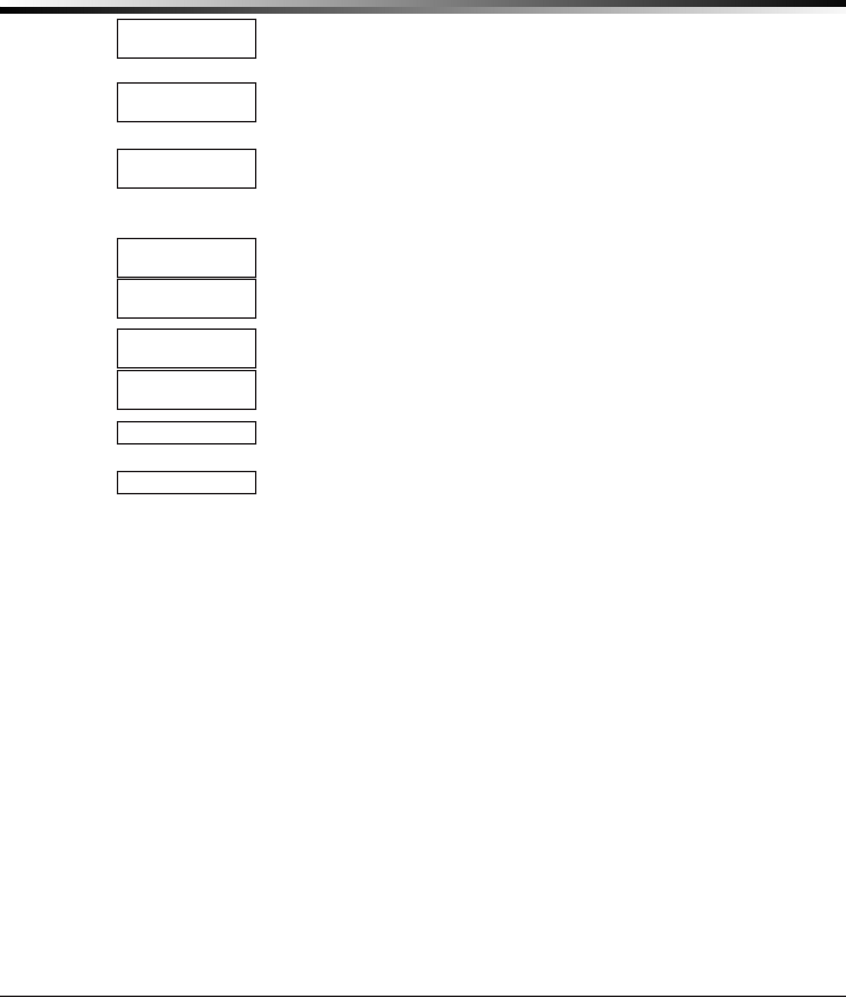
7.1 Initialization
This function allows you to set the communicator’sprogrammedmemorybacktothe
factory defaults in preparation for system programming.
AfteryouselectYEStoclearasectionofmemory,thecommunicatorasksifyouaresure
you want to clear the memory. This is a safeguard against accidently erasing part of your
programming.NomemoryisclearedfromtheprogramminguntilyouanswerYEStothe
SURE?YES NOprompt.
7.2 Clear All Codes
NOleavesexistingcodesintact.
YESclearstheusercodememoryandassignstheusercodenumber99touser20.
7.3 Clear All Schedules
NO -Leavesexistingschedulesintact.
YES - Clears all schedules from the programming.
7.4 Clear Events
NO leaves existing event memory intact.
YES clears all event memory currently held in the communicator’sDisplayEventsbuffer.
7.5 Clear Zone Programming
NO leaves existing zone information intact.
YES setsallzonesinthesystemto*UNUSED*
7.6 Clear Communication
NO - Leavesexistingcommunicationprogrammingintact.
YES - Clears communication to factory defaults.
7.7 Set to Factory Defaults
NO leaves the remainder of the existing communicator programming intact.
YES sets the communicatorprogrammingbacktofactorydefaultselectionsandclears
allZ-WavedeviceprogrammingandFavoritesfromthecommunicator.SelectingYES
does not clear the event memory, zone, user code information, or schedules.
INITIALIZATION
CODES? NO YES
SURE? YES NO
SCHEDS? NO YES
SURE? YES NO
EVENTS? NO YES
SURE? YES NO
ZONES? NO YES
SURE? YES NO
COMMS? NO YES
SURE? YES NO
DEFAULTS? NO YES
SURE? YES NO
CODES? NO YES
SCHEDS? NO YES
For each section of the panel program you can
initialize, a NO or YES option is provided.
Selecting YES advances you to
a confirmation prompt.
If you select YES, the panel initializes that section of
the program and advances you to the next prompt.
If you select NO, the panel advances you to the next
section prompt but does not initialize that section of
the program.
SURE? YES NO
Selecting NO
advances you to
the next prompt.

CellComSL
Series Communicator Install/Programming Guide Digital Monitoring Products
15
COMMUNICATION
Communication
8.1 Communication
TheCommunicationsectionallowsyoutocongurethecommunicationsettingsforthe
CellComSL
SeriesCellularAlarmCommunicator.AfterchoosingtheCommunicationType,
continue through the list of options.
8.2 Account Number
Entertheaccountnumbersenttothereceiver.
CELL-Therangeofaccountnumbersis1to65535.Foraccountnumbersoffourdigits
or less, you do not have to enter leading zeros. The
c
ommunicator automatically right
justiestheaccountnumber.
8.3 Transmission Delay
Enterthenumberofseconds(15to45seconds)thecommunicator waits before sending
burglaryalarmreportstothereceiver.Enter0(zero)todisablethisfunction.The
defaultis30.
IftheareawherethealarmoccurredisdisarmedduringtheTransmitDelaytime,only
anAbortReport(S45)messageissenttothereceiver.Iftheareawherethealarm
occurred is disarmed after the alarm message is sent to the receiver but before the Bell
Cutofftimeexpires,evenifthealarmwassilenced,anAlarmCancelled(S49)messageis
sent.TheAlarmCancelledreportcannotbedisabled.
8.4 Communication Type
The
c
ommunicatorusesCELLcommunicationtoDMPModelSCS-1RorSCS-VRReceivers.
8.5 Test Time
PressCOMMANDtoentertheTestTime.Enterthetimeofdaythecommunicator sends
thetestreporttotheSCS-1RorSCS-VRReceivers.Useentriesbetween12:00to11:59
andthenchooseAMorPM.
8.6 Cell Check In
Check-inreportsareamethodofsupervisingthepanelforcommunicationwiththe
receiver.
Enterthenumberofminutesbetweencheck-inreports.Selectfrom0or3-240minutes.
Enter0(zero)todisablethecheck-inoption.Defaultis0.
Note:IfCellCheck-inoptionisused,additionalcellchargesmayapply.
8.7 Fail Time
FailTimeallowstheSCS-1RorSCS-VRreceivertomissadenednumberofcheck-ins
before logging that the panel is missing. For example, if CELL CHECKIN is20andFAIL
TIMEis30,theSCS-1RreceiveronlyindicatesaPanelNotRespondingafter30minutes.
The FAIL TIME must be equal to or greater than the CELL CHECKIN minutes: If the
CHECKINis20minutes,theFAIL TIME mustbe20ormore.ThemaximumFAIL TIME is
240minutes.Selectfrom0or3-240minutes.ThedefaultFAIL TIME is240minutes.
8.8 Receiver 1 Programming
Allowsyoutosettheoptionsfortherstreceiverthe
c
ommunicator attempts to
contact when sending reports. The
communicator
supports communication to two
receivers.
8.9 Alarm Reports
YESenablesAbort,Alarm,AlarmRestoral,AlarmBellSilenced,Ambush,ExitError,and
SystemRecentlyArmedreportstobesenttothisreceiver.DefaultisYES
8.10 Supervisory/Trouble Reports
YESenablesSupervisory,Trouble,TroubleRestoral,ForceArmed,LatetoClose,and
Faultreportstobesenttothisreceiver.DefaultisYES.
8.11 Opening/Closing and User Reports
YESenablesOpening/Closing,DoorAccess,ScheduleandCodeChanges,andBypass
reportsbyusertobesenttothisreceiver.DefaultisYES.
8.12 Test Report
EnterYEStoenabletheRecallTestreporttobesenttothisreceiver.
8.13 First IP Address
Entertherst(primary)IPaddresswherethe
c
ommunicator sends cell messages. The IP
addressmustbeuniqueandcannotbeduplicatedonthenetwork.Enterall12digitsand
leaveouttheperiods.Forexample,enterIPaddress192.168.0.250as192168000250.
The periods display automatically.
COMMUNICATION
ACCOUNT NO:
XMIT DELAY: 0
COMM TYPE: CELL
TEST TIME
00:00 AM PM
CELL CHECKIN: 0
FAIL TIME: 240
RECEIVER 1 PROG
ALARM NO YES
SPV/TRBL NO YES
O/C USER NO YES
TEST RPT NO YES
FIRST IP ADDR
000.000.000.000

Digital Monitoring Products
CellComSL
Series Communicator Install/Programming Guide
16
COMMUNICATION
8.14 First IP Port
EntertherstIPportnumbertobeusedinconjunctionwiththeFirstIPAddress.TheIP
portidentiestheportusedtocommunicatemessagestoandfromthecommunicator.
ThedefaultIPPortsettingis2001.
8.15 Second IP Address
EnterthesecondIPaddresswherethecommunicator sendsnetworkmessages.TheIP
Addressmustbeuniqueandcannotbeduplicatedonthenetwork.Enterall12digitsand
leaveouttheperiods.Forexample,enterIPaddress192.168.0.250as192168000250.
The periods display automatically.
8.16 Second IP Port
EnterthesecondIPportnumbertobeusedinconjunctionwiththeSecondIPAddress.
TheIPportidentiestheportusedtocommunicatemessagestoandfromthe
communicator.ThedefaultIPPortsettingis2001.
8.17 Receiver 2 Programming
Allowsyoutosettheoptionsforthesecondreceiverthecommunicator attempts to
contact when sending reports. The communicator supports communication to two
receivers.IfyouselectYESforanyoftheReceiver2options,youmusthaveatleastone
IPaddressprogrammedinReceiver2programming.Receiver2defaultsaresettoNO.
8.18 Alarm Reports
YESenablesAbort,Alarm,AlarmRestoral,AlarmBellSilenced,Ambush,ExitError,and
SystemRecentlyArmedreportstobesenttothisreceiver.DefaultisNO.
8.19 Supervisory/Trouble Reports
YESenablesSupervisory,Trouble,TroubleRestoral,ForceArmed,LatetoClose,and
Faultreportstobesenttothisreceiver.DefaultisNO.
8.20 Opening/Closing and User Reports
YESenablesOpening/Closing,DoorAccess,ScheduleandCodeChanges,Bypass,and
SensorResetreportsbyusertobesenttothisreceiver.DefaultisNO.
8.21 Test Report
YESenablestheRecallTestreporttobesenttothisreceiver.DefaultisNO.
Messaging Setup
9.1 Messaging Setup
This section allows you to enter the information needed to send and receive messages
directlytoandfromthepanelviaE-MailandMyAccess™textmessagingusingCDMA
cellularcommunication.Allofthenameandpasswordoptionsbelowallowupto32
lowercasecharacterstobeentered.TheDestinationaddressesallowupto48characters
tobeentered.SystemNameisdisplayedwithinitialcaps.
The transmitted messages are:
•ZoneAlarmsbyZoneName
•ZoneTroublesbyZoneName
•ZoneBypassbyUser
•Arming(Closings)byUser
•Disarming(Openings)byUser
•LatetoClose
•LatetoOpen
•EarlytoClose
•ACPowerTroubleandRestoral
•SystemLowBattery
•Ambush
•Abort,CancelandAlarmVeriedbyUser
•Check-inbyUser
9.2 Enable Messaging
SelectYEStoallowthepaneltosendmessagestothreeprogrammeddestinations.
DefaultisNO.
FIRST IP PORT
2001
SECOND IP ADDR
000.000.000.000
SECOND IP PORT
2001
RECEIVER 2 PROG
ALARM NO YES
SPV/TRBL NO YES
O/C USER NO YES
TEST RPT NO YES
MESSAGING SETUP
MESSAGING SETUP
ENABLE MESSAGING
NO YES
CellComSL
Series Communicator Install/Programming Guide Digital Monitoring Products
17
MESSAGING SETUP
9.3 System Name
Enterauniq
ue name for the panel. The panel name is used as the sender of the message.
The text entered is displayed w
ithinitialcaps.Ifthiseldisleftblank,thepanelaccount
number is sent.
9.4 Destination 1
Entertherstcellphonenumberwheremessageswillbesent.Themessagecanbe
senttoanydevice(computer,cellphone,PDA)aslongasavalidcellphonenumberis
entered.
9.5 Destination 1 User Number
IfDestination1isa10-digitcellularnumber,enterauser’susernumberfromthisaccount.
Thisoptionisusedwhensendingcommandssuchasarmingordisarmingbacktothepanel
usingMyAccess™textmessagingfromthesamecellphoneorPDA.Theusernumbermust
havetheauthoritytoperformthecommandsasifitoccurredatthekeypad.Entering0
(zero)disablesthisoption.Defaultis0.
9.6 Destination 2
Entertheseconddestinationcellphonenumber.
9.7 Destination 2 User Number
IfDestination2isacellularnumber,entertheuser’sUserNumberfor
arming/disarming authorization.
9.8 Destination 3
Enterthethirddestinationcellphonenumber.
9.9 Destination 3 User Number
IfDestination3isacellularnumber,entertheuser’sUserNumberfor
arming/disarming authorization.
9.11 O/C SMS
SelectYEStoallowthepaneltosendOpeningandClosingmessagestoacellphoneviaSMS
protocol.DefaultisNO.Thispromptappearsonlyifanydestinationisacellphonenumber.
9.12 Monthly Limit
This option displays if any programmed destination is a cell phone number. This
numberlimitsthemonthlyincomingandoutgoingSMSmessagesallowedtobesent
or received by the panel.
Apaneleventthatcausesmessagestobesenttodestinationcellphonenumbersis
countedtowardsthepanel’smonthlylimit.Forexample,ifSMSmessagessentfrom
a cell phone to the panel including status requests and alarm messages received
from the panel all count toward the monthly limit. The limit is reset at midnight on
the14thofeverymonth.Rangeisfrom0to999.When0isentered,thereisnolimit
onthenumberofmessagesabletobesentorreceivedbythepanel.Defaultis0.
DESTINATION 1
-
DESTINATION 2
-
DESTINATION 2
USER NUMBER:
0
DESTINATION 3
-
DESTINATION 3
USER NUMBER:
0
SYSTEM NAME
-
O/C SMS NO YES
MONTHLY LIMIT: 0
DESTINATION 1
USER NUMBER:
0

Digital Monitoring Products
CellComSL
Series Communicator Install/Programming Guide
18
REMOTE OPTIONS
Remote Options
10.1 Remote Options
This section allows you to enter the information needed for Remote Command/Remote
Programmingoperation.AdescriptionoftheRemoteOptionsfollows:
10.2 Remote Key
This option allows you to enter a code of up to eight digits for use in verifying the
authority of a receiver to perform a remote command/programming session. The
receivermustgivethecorrectkeytothe
c
ommunicator beforebeingallowedaccess.All
CellComSL
SeriesCellularAlarmCommunicators are shipped from the factory with the
RemoteKeypresetasblank.
ToenteranewRemoteKey,pressanySelectkeyandenteranycombinationofupto8
digits.Thenumbersyouenterappearasasterisks.PressCOMMAND.
10.3 Remote Disarm
EnterYEStoenablethe
c
ommunicatortobedisarmedremotely.SelectingNOdisables
remote disarming.
System Reports
11.1 System Reports
This function allows you to select which reports the
c
ommunicator sends to the receiver.
11.2 Opening/Closing Reports
NO-NoOpening/ClosingReportsaresent.
YES-SendsOpening/ClosingReportsforeachprogrammedarea.
11.3 Zone Restoral Reports
This option allows you to specify whether the communicator sends zone restoral reports
and when they will be sent.
NO-Restoralreportsarenotsentbythecommunicator.
YES-Thecommunicator
always sends zone restoral reports at the time the zone
restores from an alarm or trouble condition.
DISARM-Thecommunicator sends zone restoral reports when a zone that has
restored from an alarm or trouble is disarmed. Twenty-four hour zones send restorals
immediately.
System Options
12.1 System Options
This section allows you to select system wide parameters used in the operation of the
c
ommunicator system.AdescriptionofeachSystemOptionfollows:
12.2 System
Thisconguresthecommunicator
asanAreasystem.
12.3 Entry Delay 1
Entertheentrydelaytimeforallexittypezonesprogrammed.WhenanarmedExit
typezoneisfaulted,thekeypadprewarntonebeginssounding.ENTERCODE:-andthe
nameofthezonecausingtheEntryDelaydisplaysonallkeypads.
Whentherstdigitofacodeisentered,theprewarntonestopsatthekeypad.Ifwithin
veseconds,avalidusercodeisnotenteredoraninvalidusercodeisentered,the
prewarn tone begins sounding again. Fifteen seconds must elapse before entering a digit
silences the prewarn tone again.
The area must be disarmed before the entry delay expires or a fault will be detected.
AllBurglarytypezonesinallareasaredelayedalongwiththeExitzone.
Entrydelaytimescanbefrom30to250seconds.Defaultis30secondsforEntry
Delay1.
12.4 Exit Delay
EntertheExitDelaytimeforallExittypezones.Whentheexitdelaytimestarts,all
activityonexitandburglaryzonesisignoreduntiltheexitdelayexpires.Thekeypad
displaystheExitDelaytimecountdownandannunciatestheExitDelaytoneat8second
intervalsuntilthelast10secondswhenannunciationisat3secondintervals.Theexit
delaycanbefrom45to250seconds.Defaultis60seconds.
REMOTE OPTIONS
RMT KEY:
DISARM NO YES
SYSTEM REPORTS
O/C RPTS YES
RESTORAL YES
NO YES DISARM
SYSTEM OPTIONS
SYSTEM: AREA
ENTRY DLY 1: 30
EXIT DELAY: 60
SYSTEM REPORTS
SYSTEM OPTIONS
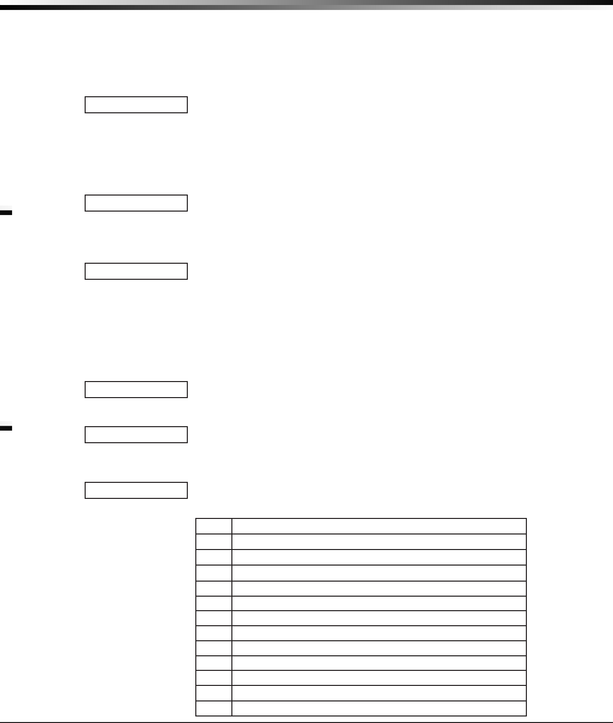
CellComSL
Series Communicator Install/Programming Guide Digital Monitoring Products
19
SYSTEM OPTIONS
DuringExitDelay,ifanexitzonetrips,thenrestores,andtripsagain,theExitDelay
timer restarts. This restart can occur only once.
ExitErrorOperation:Atarming,whenanentry/exitzone(EX)isfaultedattheendof
the exit delay then one of two sequences occur:
ForEntryDelayEXtypezones:
• the bell sounds for the length of time set in Bell Cutoff programming
• theEntryDelayoperationstarts,requiringcodeentrytodisarm
• ifnotdisarmed,azonealarmandanExitErroraresenttothereceiver.
12.5 Cross Zone Time
Enterthetimeallowedbetweenzonefaults.Whenazoneprogrammedforcrosszoning
faults, the
c
ommunicatorbeginscountingdowntheCross-ZoneTimeenteredhere.Ifthe
same zone or another cross-zoned zone faults within this time, an alarm report is sent to
the receiver.
IftheCross-ZoneTimeexpireswithoutthesecondzonefault,onlyazonefaultreport
fromtherstzoneissenttothereceiver.TheCross-ZoneTimecanbefrom4to250
secondsinonesecondincrements.Enter0(zero)todisabletheCross-ZoneTimefeature.
SeetheAppendix.
12.6 Power Fail Delay
Thisoptiontracksthedurationofaprimarypowerfailure.Thedelaytimecanbefrom1
to9hours.Whenthepowerisoffforthelengthoftheprogrammeddelaytime,apower
failure report is sent to the receiver. For example, if the power failure delay is set for
twohours,thenthepowerfailurereportwillbesentbetween2-3hours.Enteringa0
(zero) sends the power failure report within 15 seconds.
12.7 Swinger Bypass Trips
Enterthenumberoftimes(1-6)azonecangointoanalarmortroubleconditionwithin
one hour be fore being auto matically bypassed. Bypassed zones are auto matically reset
whentheareatheyareassignedtoisdisarmed.All24-hourzonesareresetwhenany
areaofthesystemisdisarmed.AprogrammingStopoperationrestoresabypassedzone.
Entering0(zero)disablesthisfunction.Defaultis2.
How it works
The communicatorhourtimerstartsat59minutespastthehour.Ifthehourtimer
expiresbeforethetripcounterisexceeded,thetripcounterreturnsto0(zero).Ifthe
trip counter is exceeded before the hour expires, the zone is auto matically bypassed by
the communicator.ABypassReportissenttothereceiverifBypassReportsisYES.
12.8 Reset Swinger Bypass
WhenYESisselected,anautomaticallybypassedzoneisresetifitremainsinanormal
conditionforonecompletehourafterbeingbypassed.Areportoftheautomaticresetis
senttothereceiverifBypassReportshasbeenselectedasYES.DefaultisNO.
12.9 Time Zone Changes
This option allows the communicatortorequestautomatictimechangesfromtheDMP
SCS-1RorSCS-VR Receiver. For the receiver to send time changes, it must be
programmed to send time changes and must be receiving time change updates from the
hostautomationcomputeratleastevery24hours.DefaultisYES.
WhentimezoneisprogrammedYES,enterthenumber(0-23)thatindicatesthe
GreenwichMeanTimezone(GMT)wherethecommunicator is located. The default is 6.
SeetablebelowforGMTvalues.
GMT City/Time Zone
0London, Monrovia, Lisbon, Dublin, Casablanca, Edinburgh
1Cape Verde Island, Azores
2Mid-Atlantic, Fernando de Noronha
3Buenos Aires, Georgetown, Brasilia, Rio de Janeiro
4Atlantic Time (Canada), Caracas, La Paz, Santiago
5Eastern Time (US, Canada) Bogota, Lima, Arequipa
6Central Time (US, Canada), Mexico City, Saskatchewan
7Mountain Time (US, Canada), Edmonton
8PacicTime(US,Canada),Tijuana
9Alaska
10 Hawaii
11 Midway Island, Samoa
CRS ZONE TM: 0
PWR FAIL HRS: 1
SWGRBYPS TRIPS: 2
RST SBYP NO YES
TIME CHG NO YES
HRS FROM GMT: 6

Digital Monitoring Products
CellComSL
Series Communicator Install/Programming Guide
20
12 Fiji,MarshallIsland,Wellington,Auckland,Kwajalein,Kamchatka
13 New Cadelonia
14 Guam, Sydney
15 Tokyo, Seoul
16 Hong Kong, Singapore
17 Bangkok, Hanoi
18 Dhaka, Almaty
19 Islamabad, Karachi
20 Abu Dhabi, Kazan
21 Moscow, Bagdad
22 Eastern Europe
23 Rome, Paris, Berlin
12.10 Weather Zip Code
ThisoptionallowslocalU.S.A.weatherupdatestodisplayonthekeypad.Enterthezip
codeoftheuseratthisprompt.Whennonumberisenteredweatherconditionsarenot
displayed.Defaultis0(zero).
Output Options
13.1 Output Options
This section allows you to program
c
ommunicator outputoptions.SwitchedGround
(opencollector)outputsareavailableusingterminalsO1andO2asthegroundandyour
burglary
control panel
forpower.Selectfromoutputs1or2.
13.2 Cutoff Outputs
Thisoptionallowsyoutodenetheoperationofthetwoon-boardoutputs.Foreach
programmingoption,enterthenumberoftheoutputyouwishtoactivateor0(zero)for
nooutput.Eitherorbothoftheavailableoutputscanbeprogrammedheretoturnoff
afterthetimespeciedinOutputCutoffTime.Todisablethisoption,pressanySelect
keytoclearthedisplayofoutputnumbersandthenpressCOMMAND.
13.2.1 Output Cutoff Time
IfaCutoffOutputisassigned,youcanenteraCutoffTimefortheoutputtoremain
on up to 15 minutes. If the output is turned off manually, the cut off time is reset. The
CutoffTimecanbe1-15minutes.Enter0(zero)toprovidecontinuousoutput.
Note:Theoutputiscutoffwithin60secondsoftheprogrammedcutofftime.
The Cutoff Timer is shared by all outputs. If a second output trips, the timer is not
reset. Both outputs turn off when the original time expires.
13.3 Communication Failure Output
ThisOutput/Favoriteturnsonwhenthe
c
ommunicator fails to communicate with the
receiverafterthreesuccessivedialattempts.Enter0(zero)todisablethisoutput.To
turnofftheCommunicationFailureOutput,disarmthecommunicator.
Note:FavoritesareonlyavailableontheCellComSLCZCommunicator.
13.4 Armed Output
ThisOutput/Favoriteturnsonanytimeanareaofthesystemisarmed.Theoutputturns
offwhenthesystemcompletelydisarms.Enter0(zero)todisablethisoutput.
13.5 Heat Saver Temperature (
CellComSL
CZ only)
EnterthedesiredtemperaturesettingforallZ-Wavethermostatswhenthesystem
isarmedALLorAWAY.Whenthesystemisdisarmedthethermostatsreturntotheir
previoussettings.Therangeis55-95degrees.Enter0(zero)todisable.
13.6 Cool Saver Temperature (
CellComSL
CZ only)
EnterthedesiredtemperaturesettingforallZ-Wavethermostatswhenthesystem
isarmedALLorAWAY.Whenthesystemisdisarmedthethermostatsreturntotheir
previoussettings.Therangeis55-95degrees.Enter0(zero)todisable.
ENTER WEATHER
ZIP CODE: 0
OUTPUT OPTIONS
CO OUTS: - - -
CUTOFF TIME: 0
COM FAIL OUT: 0
ARMED OUT: 0
HEAT SAVER
TEMPERATURE: 0
COOL SAVER
TEMPERATURE: 0
SYSTEM OPTIONS
OUTPUT OPTIONS

CellComSL
Series Communicator Install/Programming Guide Digital Monitoring Products
21
AREA INFORMATION
Area Information
14.1 Area Information
This section allows you to assign functions to the burglary area of the communicator.
Allnon-24-hourzonesmustbeassignedtoanactivearea.SeethesectiononZone
Information.
14.2 Area Number
OnlyArea1isavailabletoprogram.
14.3 Area Name
DefaultAreaNameisAREA1.Tochangetheareanameinthesystem,pressanySelect
keyandthenenterupto16charactersforthenewname.PressCOMMANDtocontinue.
RefertotheEnteringAlphaCharacterssection.
14.4 Automatic Arming
SelectYEStoallowthisareatoarmautomaticallyaccordingtotheopeningandclosing
schedule.
IfClosingCheckisselectedasYES,theautomaticarmingdoesnottakeplaceuntilthe
expirationofa10-minuteClosingCheckdelay.Iftheareahasbeendisarmedoutsidea
schedule,theClosingCheckdelayoccursonehouraftertheareaisdisarmed.
Atarming,faultedzonesarehandledaccordingtotheoptionselectedinBadZones.If
aClosingreportissent,theusernumberisindicatedasSCHontheSCS-1RorSCS-VR
Receivers.SelectNOtodisableautomaticarmingforthisarea.DefaultisNO.
14.5 Automatic Disarming
NOdisablesautomaticdisarmingbyscheduleforthisarea.SelectYEStoallowthisarea
toautomaticallydisarmaccordingtoaschedule.IfanOpeningreportissenttothe
receiver,theusernumberisindicatedasSCH.
Zone Information
15.1 Zone Information
Thisallowsyoutodenetheoperationofeachprotectionzoneusedinthesystem.
15.2 Zone Number
The
c
ommunicatorhasfourzonestoprogram.Enterthenumberofthezoneyouintend
toprogram.PressCOMMANDtoenterazonename.RefertotheEnterAlphaCharacters
section.
15.3 Zone Name
PressanySelectkeyandenterupto16charactersforthezonename.Anamemustbe
giventoeachzoneinthesystem.Thisnamecanbedisplayedatthekeypadswhenthe
zoneisbadorviewedinDisplayEvents.Thezonenameisalsosenttothereceiveras
part of a zone event report.
Azonethatisnotpartofthesystemmustbemarked*UNUSED*.Tomarkazoneunused,
deletetheoldnamebypressinganySelectkey,thenpresstheCOMMANDkey.Thepro-
grammerautomaticallyprogramsthenameas*UNUSED*.IfyouselectedZONES?NO
YEStoclearthecommunicator’smemoryduringInitialization,thezoneswillalreadybe
marked*UNUSED*.SeetheInitializationsection.
15.4 Zone Type
TheZoneTypedenestheresponseofthecommunicator to the zone being open or
short.RefertotheAppendixforzonetypedefaultsanddescriptions.
WhenyouassignaZoneTypetoazone,responsesaremadeautomaticallyforthezone.
Thereare11ZoneTypestochoosefromincludingBlank.Thefunctionaldetailsofeach
responsearedescribedinZoneTypeDefaultsintheAppendix.
ToselectanewZoneType,pressanySelectkey.ThedisplayliststhefourZoneTypes
shownbelow.WhentheZoneTypeyouwanttoselectdisplays,presstheSelectkey
below the name.
Blank,Night,Day,orExit.PressCOMMANDtodisplayadditionalzonetypes.
Fire,Panic,Emergency,orSupervisory.PressCOMMANDtodisplayadditionalzonetypes.
Auxiliary1,Auxiliary2,FireVerify,orArming.PresstheBackArrowkeytodisplaythe
previous zone types.
IfyouselectBlank,Night,Day,Exit,Auxiliary1,orAuxiliary2astheZoneType,the
zonemustbeassignedtoanarea.IfyouselectFire,Panic,Emergency,orSupervisoryas
theZoneType,theseare24-hourzonesthatarealwaysarmedandnoareaassignmentis
needed.PressCOMMANDtocontinue.
RefertotheAppendixforzonetypespecicationsanddescriptions.
AREA INFORMATION
AREA 1
AUTO ARM NO YES
AUTO DIS NO YES
ZONE INFORMATION
ZONE NO: -
* UNUSED *
ZONE TYPE: BLANK
ZONE INFORMATION
A1 A2 AR FV
FI PN EM SV
AREA NO: -
-- NT DY EX

Digital Monitoring Products
CellComSL
Series Communicator Install/Programming Guide
22
ZONE INFORMATION
15.5 Area Assignment
Allnon-24-hourzonesareautomaticallyassignedtoArea1.
15.6 Arming Zone Assignment
AllArmingzonesareautomaticallyassignedtoArea1.
15.7 Style
Thisoptionspeciesthestyleforthearming/disarmingoperation.Thedefaultfor
STYLE:isTGL(toggle).PressinganySelectkeydisplaystheSTYLEoptions.Toviewmore
styleoptionspressthecommandkey.Thefollowingisadescriptionoftheactionfor
each option condition.
TGL(Toggle)-Whenthezonechangesfromnormaltoshorted,theprogrammedareas
togglebetweenthearmedordisarmedcondition.Whenrestoredtonormal,noaction
occurs.Whenthezoneisopenedfromanormal(disarmed)state,atroubleisreported.
Whenopenedfromashorted(armed)state,analarmisreportedandthezoneis
disableduntilyoudisarmthearea(s)fromeitherakeypadorRemoteLink™computer.
ARM-Whenthezoneisshorted,theprogrammedareaisarmed.Whenrestoredto
normal,noactionoccurs.Whenthezoneisopenedfromanormal(disarmed)state,a
troubleisreported.Whenopenedfromashorted(armed)state,analarmisreported.
DIS(Disarm)-Ashortwilldisarmthearea.Whenrestoredtonormal,noactionoccurs.
Whenthezoneisopenedfromanormal(disarmed)state,atroubleisreported.
STEP-Ashortwillarmtheareaandbeepthekeypadonce.Anormalconditionwillcause
noaction.Anopenconditionwilldisarmtheprogrammedareaandbeepthekeypadfor
one second.
Note:Whenusinganarming/disarmingkeyswitch,locatethekeyswitchwithinthe
protected area.
MNT(Maintain)-Whenthezoneisshorted,theprogrammedareaisarmed.When
restored to normal, the programmed area is disarmed and any alarm bells are silenced.
Whenthezoneisopenedfromanormal(disarmed)state,atroubleisreported.If
opened from a shorted (armed) state, an alarm is reported and the zone is disabled until
youdisarmtheareafromeitherakeypadorRemoteLink™computer.
15.8 Next Zone
WhenYESisselected,theprogrammingforthezoneterminatesandthedisplayreturns
toZONENO:-allowingyoutoenteranewzonenumber.SelectNOtomakechangesto
theAlarmActionforazone.
15.9 Alarm Action
TheAlarmActionsectionallowsyoutochangeorconrmthedefaultalarm
characteristics of a zone type.
Ifyouselectedthenon-24-hourzonetypeBlank,Night,Day,Exit,Auxiliary1,or
Auxiliary2,theAlarmActionprogramingbeginswithDisarmedOpen.
Ifyouselectedthe24-hourzonetypePanic,Emergency,orSupervisory,theAlarmAction
programmingbeginswithArmedOpen.
15.10 Disarmed Open
Denestheactiontakenbythecommunicator when the zone is opened while the area is
disarmed.Therearethreeactionstodene:
• MessagetoTransmit
• Output/FavoriteNumber
• OutputAction
YoumustalsomaketheseselectionsfortheDisarmedShort,ArmedOpen,andArmed
Shortzoneconditions.PresstheCOMMANDkeytocontinue.
15.11 Message To Transmit
Youcansendtworeporttypestothereceiver:AlarmandTrouble.Thesearerepresented
bythecharactersAandT.PressanySelectkeytodisplaythezonereportoptions.
ALARM-SelectingAallowsanalarmreporttobesenttothereceiver.SeetheBellAction
section. The zone name appears in the communicator’salarmedzonesstatuslists.
TROUBLE-SelectingTallowsatroublereporttobesenttothereceiverandthezone
name to appear in the communicator’salarmedzonesstatuslists.
LOCAL-WhenyouselectL,analarmreportisNOTsenttothereceiver.Thebelloutput
still activates according to zone type and the zone name appears in the communicator’s
alarmed zones status lists.
–(dash)-Whenyouselect–,reportsareNOTsenttothereceiver.Thebelloutputdoes
not activate and there is no display in the communicator’salarmedzonesstatuslist.
OnlytheprogrammedOutputNumberactivates.
15.12 Output Number
AREA NO: -
AREA:
STYLE: TGL
TGL ARM DIS STEP
MNT
NEXT ZN? NO YES
ALARM ACTION . . .
DISARMED OPEN
MSG: ALARM
A T L -
OUTPUT NO: 0

CellComSL
Series Communicator Install/Programming Guide Digital Monitoring Products
23
ZONE INFORMATION
Youcanspecifyanyoftheoutputs/Favoritesonthecommunicator to be activated by
a zone condition. The output/Favorite can be activated regardless of the report to
transmitorwhetherornotthezoneisprogrammedaslocal.Anoutputactivatedbya
non-24-hourarmedzoneisturnedoffwhenthezone’sareaisdisarmedbyauser.To
enteranOutputNumber,pressanySelectkeyfollowedbytheoutputnumber1or2.
PresstheCOMMANDkey.
15.13 Output Action
EnteringanOutputNumberdisplaysthispromptthatallowsyoutoassignanoutput
actiontotherelay.Adescriptionoftheavailableoutputactionsisgivenbelow:
STEADY-Theoutputisturnedonandremainsonuntiltheareaisdisarmed,anoutput
cutofftimeexpires,ortheoutputisresetfromthekeypadUserMenu.
PULSE-Theoutputalternatesonesecondonandonesecondoffuntiltheareais
disarmed,anoutputcutofftimeexpires,ortheoutputisresetfromthekeypadUser
Menu.
MOMENTARY-Theoutputisturnedononlyonceforonesecond.
FOLLOW-Theoutputisturnedonandremainsonwhilethezoneisinanoffnormal,or
badcondition.Whenthezonerestores,theoutputisturnedoff.
AfteryouhaveselectedtheMessageToTransmit,thedisplaypromptsyouforthesame
threeselectionsforDisarmedShort,ArmedOpen,andArmedShortconditions.Ifthe
zoneisa24-hourtype,onlytheArmedOpenandArmedShortconditionsaredisplayed.
Whenyouhaveprogrammedallofthezoneconditions,theSwingerBypassselectionis
then dis played.
15.14 Swinger Bypass
SelectingYESallowsthezonetobeswingerbypassedbythecommunicator according to
theprogramminginSwingerBypassTripsandResetSwingerBypass.TheBypassedzone
displaysinthekeypadStatusList.SelectingNOdisablesswingerbypassingforthiszone.
How it works
Ifwithinonehour,azonetripsthetotalnumberoftimesasspeciedinSwingerBypass
Trips, the communicatorbypassesituntilthefollowingconditionsoccur;theareain
which the zone is assigned is disarmed, the zone is manually reset through the Bypass
ZoneskeypadUserMenufunction,thezoneremainsnormalforonehourandtheReset
SwingerBypassisYES.
Ifthezonetripsfewerthanthespeciedtimeswithinonehourofthersttrip,the
bypasstripcounterreturnsto0(zero)andtheprocessmustberepeated.
AreportoftheswingerbypassissenttothereceiverifBypassReportsisYES.
15.15 Cross Zone
SelectYEStoenablecross-zoningforthiszone.Cross-zoningrequiresthiszonetotrip
twice, or this zone and another cross-zoned zone to trip, within a programmed time
before an alarm report is sent to the receiver. To operate correctly, all cross-zone zones
need to be programmed as the same zone type.
Whenacross-zonedzonetrips,theOutputactionassignedtothezoneactivates.See
theBellActionsection.Thecross-zonetimespeciedinSystemOptionsbeginstocount
down.SeetheCross-ZoneTimesection.Ifanothercross-zonedzoneinthesystem
faults,oriftherstzonerestoresandfaultsagainbeforethecross-zonetimeexpires,
the bell turns on and the communicator sends an alarm report.
If no other cross-zone zone in the system trips before the cross-zone time expires, the
communicatorsendsonlyafaultreportfromtherstzonetothereceiver.
Note:IfCRSZONEisYES,avalidCRSZNTIMEmustbeprogrammedforthisfeatureto
be enabled.
15.16 Receiver Routing
ThisoptiondisplaysifZoneTypeissetforAuxiliary1orAuxiliary2.
PressanytoprowkeytoselecttheReceiverRoutingfortheselectedzone.
SelectNORMtosendAlarmandSupv/Trblmessagesfromthiszonetoreceiver1or
receiver2asprogrammedwithinthereceiverinCommunications.
Select1tosendAlarmandSupv/Trblmessagesfromthiszonetoreceiver1only,
regardless of the programming for the receiver in Communications.
Select2tosendAlarmandSupv/Trblmessagesfromthiszonetoreceiver2only,
regardless of the programming for that receiver in Communications.
SelectBOTHtosendAlarmandSupv/Trblmessagesfromthiszonetobothreceivers,
regardless of the programming for either receiver in Communications.
15.17 Zone Number
Enterthezonenumberyouwanttoprogramnext.Returntosection15.1andfollow
the descriptions of each programming prompt. If all zones are programmed, press the
ARROWkeyattheZONENO:–displaytocontinue.
ACTION:
STD PLS MOM FLW
SWGR BYP NO YES
CRS ZONE NO YES
RECEIVER ROUTING
NORMAL
NORM 1 2 BOTH
ZONE NO: -

Digital Monitoring Products
CellComSL
Series Communicator Install/Programming Guide
24
Stop
16.1 Stop
AttheSTOPprompt,pressinganySelectkeyallowsyoutoexittheprogrammerfunction
of the communicator.Whenselected,thecommunicator performs an internal reset and
exitstheprogrammer.TheStopfunctioncausesthefollowingconditionstooccur:
•ThesystemisDISARMED
•Thecommunicator’sStatusListisCLEARED
DuringtheStopfunction,allkeypaddisplaysaremomentarilydisabledfortwoseconds.
Afterwards,theprogrammingfunctionisterminatedandthekeypadsreturntothe
StatusListdisplay.
Set Lockout Code
17.1 Set Lockout Code
PressingCOMMANDattheStoppromptdisplaysSETLOCKOUTCODE.Thisfeature
allows you to program a special code that will then be required to gain access to the
communicator’sinternalProgrammerthroughthekeypad.
ChangingtheLockoutCode
Youcanchangethiscodeatanytimetoanycombinationofnumbersfrom1to5digits
long(1to65535).Donotuseleadingzerosforthelockoutcode.
1. PressanySelectkey.ThedisplaychangestoENTERCODE:-.
2. Entera1-to5-digitcode(donotenteranumberhigherthan65535).Press
COMMAND.
3. EnterthenewLockoutCodeagain.PressCOMMAND.Thekeypaddisplaychangesto
CODECHANGED.
Onceyouhavechangedthecode,itisimportantthatyouwriteitdownandstoreitin
asafeplace.LostlockoutcodesrequirethecommunicatortobesentbackintoDMP
forrepair.YoumaycancelaLockoutCodebyentering00000attheSetLockoutCode
command prompt.
LockoutCoderestriction:
DonotsetaLockoutCodehigherthan65535.
STOP
SET LOCKOUT CODE
STOP
SET LOCKOUT CODE

CellComSL
Series Communicator Install/Programming Guide Digital Monitoring Products
25
APPENDIX
Appendix
This section of the
CellComSL
SeriesCellularAlarmCommunicatorProgrammingGuideprovidesadditionalzone
and system information.
18.1 Status List
TheStatusLististhecurrentstatusofthesystemorrecordsofrecentsystemeventsthatdisplayonalphanumeric
keypads.
Ifaneventweretooccuronthesystem,suchasanACfailure,thekeypadwouldalsodisplaytheAC POWER
-TRBL message.ThisisasystemeventthatisplacedintotheStatusListtoalerttheusertoaproblemwiththe
system.
SomeStatusListitemsremaininthedisplayuntilmanuallyclearedandsomeareclearedautomaticallywhenthe
conditionreturnstonormal.BelowisalistofstatusandeventdisplaysthekeypadcanshowintheStatusList:
Description Must be manually cleared?
FireandSupervisoryzonetroubles No-clearswhenzonerestores
Burglaryzonealarms No-clearsatdisarming.
Allotherzonealarms No-clearswhenzonerestores
Zonemonitordisplays No-clearsafterapproximately8minutes
Dayzonealerts No-clearsafterapproximately8minutes
Systemmonitortroubles No-clearswhenconditionrestores
(ACandbatterytrouble)
Armedstatusdisplay No
(SystemOn)
Disarmedstatusdisplays No
(SystemReady,SystemNotReady)
Remotekeypadmessages No
(Senttothekeypadbyyourofceorcentralstation)
Eachiteminthelistisdisplayedforfourseconds.Whentherearemultipleitemsinthelist,youcanusethe
COMMANDorBackArrowkeystoscrollforwardorbackthroughtheitems.
18.2 False Alarm Reduction
System Recently Armed report
TheSystemRecentlyArmedreport(S78)issentwhenaburglaryzonegoesintoalarmwithintwominutesofthe
system being armed.
18.3 Diagnostics Function
The communicator containsaDiagnosticsfunctionthatallowsyoutotesttheintegrityofthecellular
communication,cellularsignal,andcheckPanelSettings.TouseDiagnostics,resetthe
communicator
, enter the
Diagnosticscode2313(DIAG).
Cellular Status
Thisoptionteststheindividualcomponentsofcellularcommunication.EntryintotheCellularStatus(CELL
STATUS)menuwillcauseeachcomponentofthecellularcommunicationtobetested.Thetestwillproceeduntil
therstcomponentfailureoruntilallcomponentshavebeentestedwithpositiveresults.Thetestscreenwill
displayaftereachcomponentandwillbedisplayedfortwosecondsoruntiltheCMDkeyhasbeenpressed.
Cellular Signal Strength (CELL SIGNAL)
This option provides a way to test the cellular signal strength of the nearest tower for
thecellularcarrier.PressanytoprowSelectkeytodisplaycellsignalstrength.TheX’s
represent the numerical value of the cell signal strength in -dBm. The
▐
’srepresentthe
signalstrength0-7.
Cell Roaming Indicator
TheCellularSignalStrengthoptioninthecommunicator’sdiagnosticmenucontainsa
roamingindicator.Whenthecommunicator is roaming or not in contact with a Verizon
ownedtower,ROAMwillbedisplayedonthetoplineofthekeypadalongwiththesignal
strength.Toperformthecellularactivationprocessfromakeypad,thecommunicator
MUSTbeincontactwithaVerizonownedtower.Ifthecellularcommunicatorisin
contactwithatowerownedbyanothernetwork,ROAMandthesignalstrengthdisplays,
but activation cannot be completed. This feature can be used as a diagnostic tool to
troubleshoot activation issues.
-XX dBm
SIGNAL: ▐▐▐▐▐▐▐
ROAM -XX dBm
SIGNAL: ▐▐▐▐▐▐▐

Digital Monitoring Products
CellComSL
Series Communicator Install/Programming Guide
26
APPENDIX
WALK TEST
TRIPS: XXX END
Activate Cell
To begin the cellular activation for a
c
ommunicator,verifythattheMEIDhasbeenaddedforthe
communicator
usingRemoteLinkorbycallingCustomerService(1-800-641-4282).Atthekeypad,pressanytoprowSelectkey
when ACTIVATE CELLisdisplayedonthekeypad.WhentheSURE NO YES?conrmationmenuappearspressthe
SelectkeybeneathYEStocompletethecellularactivation.
Successful Display Failure Display
CELL ACTIVATED NOT ACTIVATED
Panel Settings
PressingatoprowkeyallowsaccesstotheMACAddress,SerialNumber,Model,andFirmwareVersion.
Serial Number
This number is the communicator serial number. Reference this number for communicator date-of-manufacture,
hardwareversion,etc.PressanytoprowSelectkeytodisplaytheSerialNumber.
Model Number
This menu option displays the model number of the
communicator
.
Firmware Version
Thismenuoptiondisplaysthermwareversionnumberofthe
communicator
and date it was released.
Z-Wave Test Option
This feature allows the installer to test
CellComSL
CZcommunicationwithZ-Wave
devices.Asuccessfultestindicatesaresponsefromadevice.PressanytoprowSelect
keytoviewtheZ-WaveDeviceList.
PressCOMMANDtoadvancethrougheachZ-WavedeviceandpressanytoprowSelect
keytobeginthetestonthedevicedisplayed.
The name of the device displays above the device number. The current number of
successful communications followed by the total number of attempts displays to the
rightofthedevicenumber.Theteststopsafter99attempts.
PressCOMMANDtoviewthenalnumberofsuccessfulcommunications.
Exiting the Diagnostics program
PresstheCOMMANDkeyuntilSTOPdisplays.PressanySelectkey.ThekeypadreturnstotheStatusListdisplay.
18.4 Using the 984 Command Function
WhennotintheProgrammingMenu,thefunction984+COMMANDcanbeenteredatthekeypad,andaremote
options menu appears. This menu contains the following options:
CELL
Thecommunicatorallowsyoutoperformatestoneachcomponentofthecellularcommunicationpaths.While
theStatusListdisplays,enter984andpresstheCOMMANDkey.PresstheSelectkeyunder CELL to allow the
communicatortoperformaCommunicationStatusTest.ThekeypaddisplaysCELL IS BUSY if the modem is being
testedfromanotherkeypad.
UponentryofaCellularpathwhenprompted,thetestrunsandtheresultsdisplayonthekeypadintheorderthey
weretested:MODEMOPERATING,IDENTIFIED,TOWERDETECTED,REGISTERED,CONNECTSUCCESS,andCELLCOM
GOOD.PressCOMMANDtoadvancethroughtheresults.WhenthetestiscompleteyouarereturnedtotheStatus
List.SeetheDiagnosticFunctionssectionforadescriptionoftheCellularStatusresults.
18.5 Using the Walk Test
Thecommunicatorprovidesawalktestfeaturethatallowsasingletechniciantotestalltheprotectiondevices
connectedtozonesonthesystem.ConducttheWalkTestwithin30minutesofresettingthecommunicator.The
WalkTestautomaticallyendsifnozonesaretrippedfor20minutes.TEST IN PROGRESSdisplaysatallkeypads.
Whenveminutesremain,TEST END WARNINGdisplays.IfanyareasarearmedtheWalkTestdoesnotstartand
SYSTEM ARMED displays.
Walk Test
ToconducttheWalkTest,resetthecommunicatorbymomentarilypressingtheRESET
button.Fromthekeypad,enterthecode8144.ThekeypaddisplaysWALK TEST. If the
systemismonitored,thesystemsendsaSystemTestBeginreporttothecentralstation.
Allprogrammedzonesareincludedinthetest.
Trip Counter for Walk Test (STD)
DisplaysthenumberofzonetripsduringtheWalkTest.
• Eachtimeaselectedzonetrips,thekeypadbuzzesandthebellringsfortwo
seconds.
TEST ZWAVE
DEVICE LIST:
HALLWAY LIGHT
HALLWAY LIGHT
LIGHT 02 0/0
HALLWAY LIGHT
99/99 SUCCESSFUL
WALK TEST

CellComSL
Series Communicator Install/Programming Guide Digital Monitoring Products
27
APPENDIX
END - PresstheSelectkeydirectlybelowENDtostoptheWalkTest.WhentheWalkTest
endsora20minutetime-outexpires,analSensorResetoccurs.TheSystemTestEnd
message is sent to the receiver along with Verify and Fail messages for each zone under
test.Faultedzonesthendisplayonthekeypad.
Test End Warning
Whennozoneshavebeentrippedandveminutesremainonthe20minuteWalkTest
timer,thekeypaddisplaysTESTENDWARNINGandthekeypadtones.Ifnoadditional
testzonetripsoccur,thetestendsandanalSensorResetautomaticallyoccurs.The
SystemTestEndmessageissenttothereceiveralongwithVerifyandFailmessagesfor
eachzoneunderWALKtest.Faultedzonesthendisplayonthekeypad.
Failed Zones Display
EachzonethatdidnottripatleastonceduringtheWalkTestdisplaysonthekeypad
thatinitiatedthetest.AnyPanic(PN)orSupervisory(SV)24-hourzonethatisfaulted
attheendoftheWalkTestdisplaysatroubleconditionforthatzoneregardlessofthe
message programmed for the open or short condition of the zone and a zone trouble is
senttothereceiver.PresstheCOMMANDkeytodisplaythenextfailedzone.
18.6 Cross Zoning
CautionmustbetakenwhencrosszoningdevicestoensurethattheCrossZoneTimeislongenoughtoallowan
intrudertotripbothdevicesbeforeitexpires.ACrossZoneTimethatistooshortmayallowanintrudertotripthe
devices and allow only a zone fault report be sent to the central station.
WhenaCrossZonedzonetrips,aFAULTreportissenttotheSCS-1RorSCS-VRReceivers.WhentwoCrossZoned
zonestripwithintheCrossZoneTime,bothzonessendALARMsignalstothereceiver.Forexample,ifzones1and
2areCrossZonedzones,andonlyzone1trips,aFAULTreportissenttothereceiverforzone1.Ifzone1tripsand
zone2tripswithintheCrossZoneTime,anALARMreportissenttothereceiverforzone1andzone2.
Note: To operate correctly, all cross-zone zones need to be programmed as the same zone type.
18.7 Zone Type Descriptions
ThissectiondescribesapplicationsforthedefaultzonetypesinZoneInformationprogramming.
NT(NightZone)-ControlledinstantzoneusedforperimeterdoorsandwindowsandinteriordevicessuchasPIRs
andglassbreakdetectors.
DY(Dayzone)-Usedforemergencydoorsorredoorstosoundthekeypadbuzzeranddisplaythezonename
whenthezoneisfaulted.Dayzonesalsowillsendalarmreportstothereceiverduringthesystem’sarmed
periods.
EX(Exitzone)-Initiatestheentrydelaytimerwhenitsassignedareaisfullyarmed.Also,caninitiateanexit
delay timer to allow a user to exit an area after the arming process has started.
PN(Paniczone)-Usedforconnectingtomechanicaldevicesthatallowausertosignalanemergencyalarm.Panic
zones can provide either a silent or audible alarm with or without reporting to a central station receiver.
EM(Emergencyzone)-Theseareusedforreportingmedicalorothernon-panicemergenciestothecentral
station.
SV(Supervisoryzone)-Usedtoprovide24-hourzonesupervision.Typicalapplicationsarehighwater,andlowand
high temperature gauges.
FI (Firezone)-Usedforanytypeofpoweredormechanicalredetectiondevice.Typicalapplicationsarefor
smokedetectors,sprinklerowswitches,manualpullstations,andbeamdetectors.
FV(FireVerifyzone)-Usedprimarilyforsmokedetectorcircuitstoverifytheexistenceofanactualre
condition.WhenaFireVerifyzoneinitiatesanalarm,thepanelperformsaFireReset.IfanyFirezoneinitiates
analarmwithin120secondsafterthereset,analarmisindicated.Ifanalarmisinitiatedafter120seconds,the
cycle is repeated.
A1 and A2(Auxiliary1andAuxiliary2)-ThesezonesaresimilartoaNightzoneandaretypicallyusedtoprotect
restrictedareaswithinaprotectedpremises.Auxiliary2zonesdonotappearintheStatusList.
AR(Armingzone)-Thiszoneallowsyoutoconnectakeyswitchtoazoneanduseittoarmanddisarmthesystem.
TEST END WARNING
SOUTH LOBBY
ZONE: 10 -FAIL

Digital Monitoring Products
CellComSL
Series Communicator Install/Programming Guide
28
APPENDIX
18.8 Zone Type Defaults
The communicator contains nine default zone types that provide the most commonly selected functions for their
applications.Allzonetypescanbecustomizedbychangingthevariableoptionslistedbelow.
Type -Thesearetheabbreviationsdisplayedonthekeypadforthezonetypes.
Area -UseArea1.
Message -A=alarmreport,T=troublereport,
L=localwithnoreport,—(dash)=noreport.
Output -The1to2switchedground(opencollector)outputs.
Action - This selects the type of relay output:
S=steady,P=pulse,M=momentary,andF=follow
Swinger Bypass - The zone can be automatically bypassed after a programmed number of trips.
Cross Zone - Provides cross zoning for this zone.
Receiver Routing -ThisselectstheroutingoptionforAuxiliary1orAuxiliary2zonetypes.
Style-Theabbreviationsthatdisplayonthekeypadforarmingzonestyle.
TGL=Toggle,
ARM=Armonly,DIS=Disarmonly,
STEP=Wirelessarming,MNT=Maintain
18.10Z-WaveCerticationInformation
The
CellComSL
CZisasecurityenabledZ-Waveproductandisdesignedtobeusedasaprimarycontroller.
TheXFERfeatureallowsanexisting3rdpartynetworktobetransferredintothe
CellComSL
CZ.
The
CellComSL
CZcansupportZ-Waveproductsfromdifferentvendorsandproductcategories.Itisrecommended
to use devices listed on the buy.dmp.com site for best performance.
Z-Waveterminology:
• InclusionistheprocessofaddingadevicetotheZ-Wavenetwork.Thenewdeviceis‘included’intothe
Z-Wavenetwork.
• ExclusionistheprocessofremovingadevicefromtheZ-Wavenetwork.Thenewdeviceis‘excluded’
fromtheZ-Wavenetwork.
• Replicationistheprocessofcopyingnetworkinformationtoanotherdevice(typicallyaZ-Wavecontroller)
intheZ-Wavenetwork.
18.11 Backlit Logo
ThebacklitlogoindicatesthePowerandArmedstatusofthecommunicator.Dependingontheoperation,the
LEDdisplaysinRedorGreenaslistedinthetable.TheLEDindicatesthestatusofthesystembatteryand
primary power.
Color and Activity Operation
GreenSteady CommunicatorDisarmed,PrimaryPowerOK,BatteryOK
GreenBlinking CommunicatorDisarmed,PrimaryPowerOK,BatteryFault
NoLight CommunicatorDisarmed,PrimaryPowerFault,BatteryOK
RedSteady CommunicatorArmed,PrimaryPowerOK,BatteryOK
Red/GreenAlternate CommunicatorArmed,PrimaryPowerOK,BatteryFault
RedBlinking CommunicatorArmed,PrimaryPowerFault,BatteryOK

CellComSL
Series Communicator Install/Programming Guide Digital Monitoring Products
29
APPENDIX

LT-1339 1.01 © 2014 Digital Monitoring Products, Inc.
800-641-4282
www.dmp.com
Designed, Engineered and
Assembled in U.S.A.
INTRUSION • FIRE • ACCESS • NETWORKS
2500 North Partnership Boulevard
Springfield, Missouri 65803-8877
14185
Specications
PrimaryPower 12VDC
CurrentDraw 180mA
Standby 120mA
Dimension
Housing 5.5”Wx3.75”Lx1”H
Color White
Accessories
XX-0000 ReplacementRechargeableBattery
Listings and Approvals
Z-Wave
FCCPart15ID:CCKPC0159
IC:5251A-PC0159
Cellular
FCCPart15:M1VCNN0301
ETLListed
ANSI/UL1610 CentralStation
Burglar
ANSI/UL1023 HouseholdBurglar
ANSI/UL985 HouseholdFire
Warning