Digital Monitoring PC0181 Security Alarm Control Panel User Manual User Guide
Digital Monitoring Products Inc Security Alarm Control Panel User Guide
UserManual.wiki
>
Digital Monitoring
>
PC0181 User Manual
User Guide
Navigation menu
Upload a User Manual
Namespaces
Wiki Guide
HTML
PDF
Info
Views
User Manual
Discussion / Help
Navigation


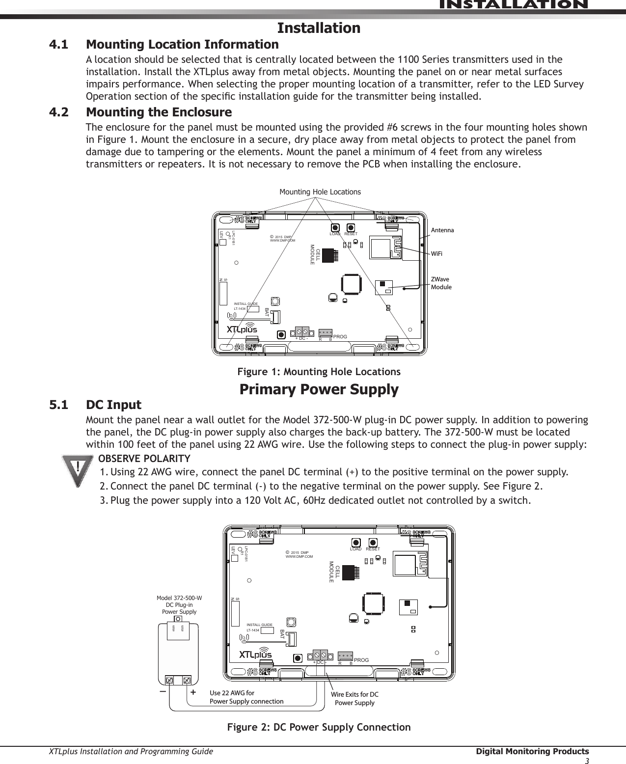
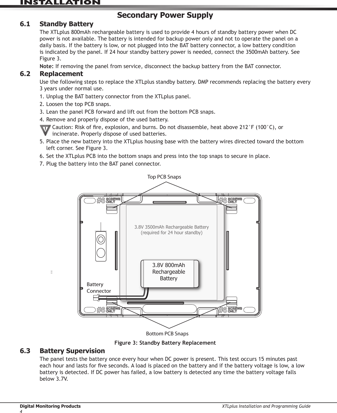
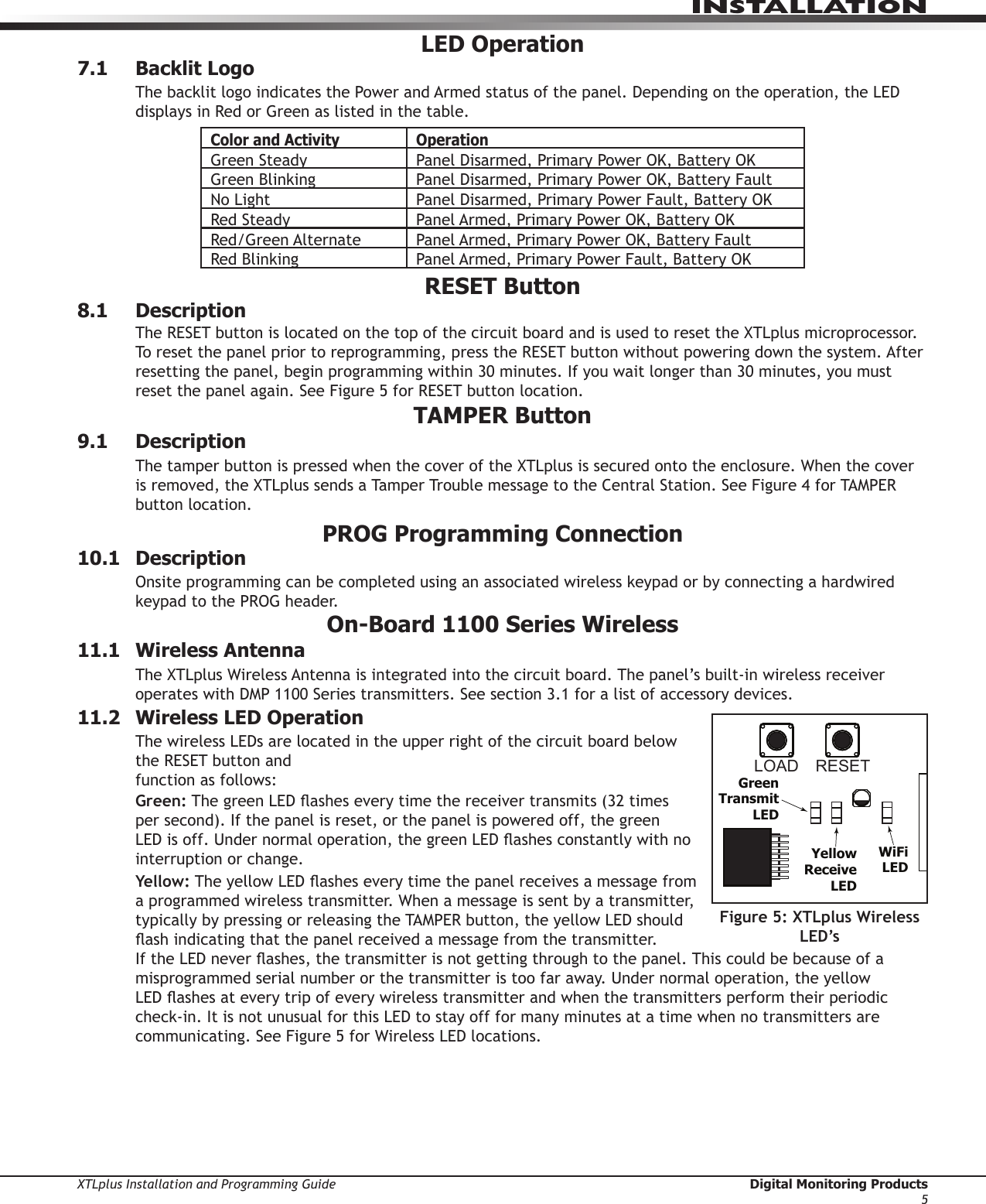
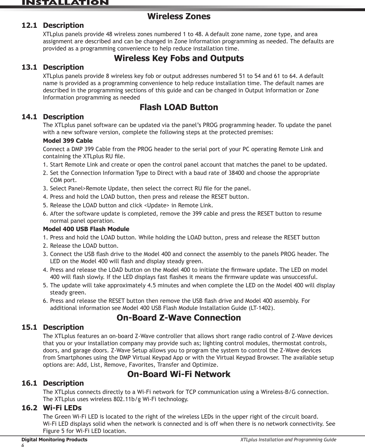
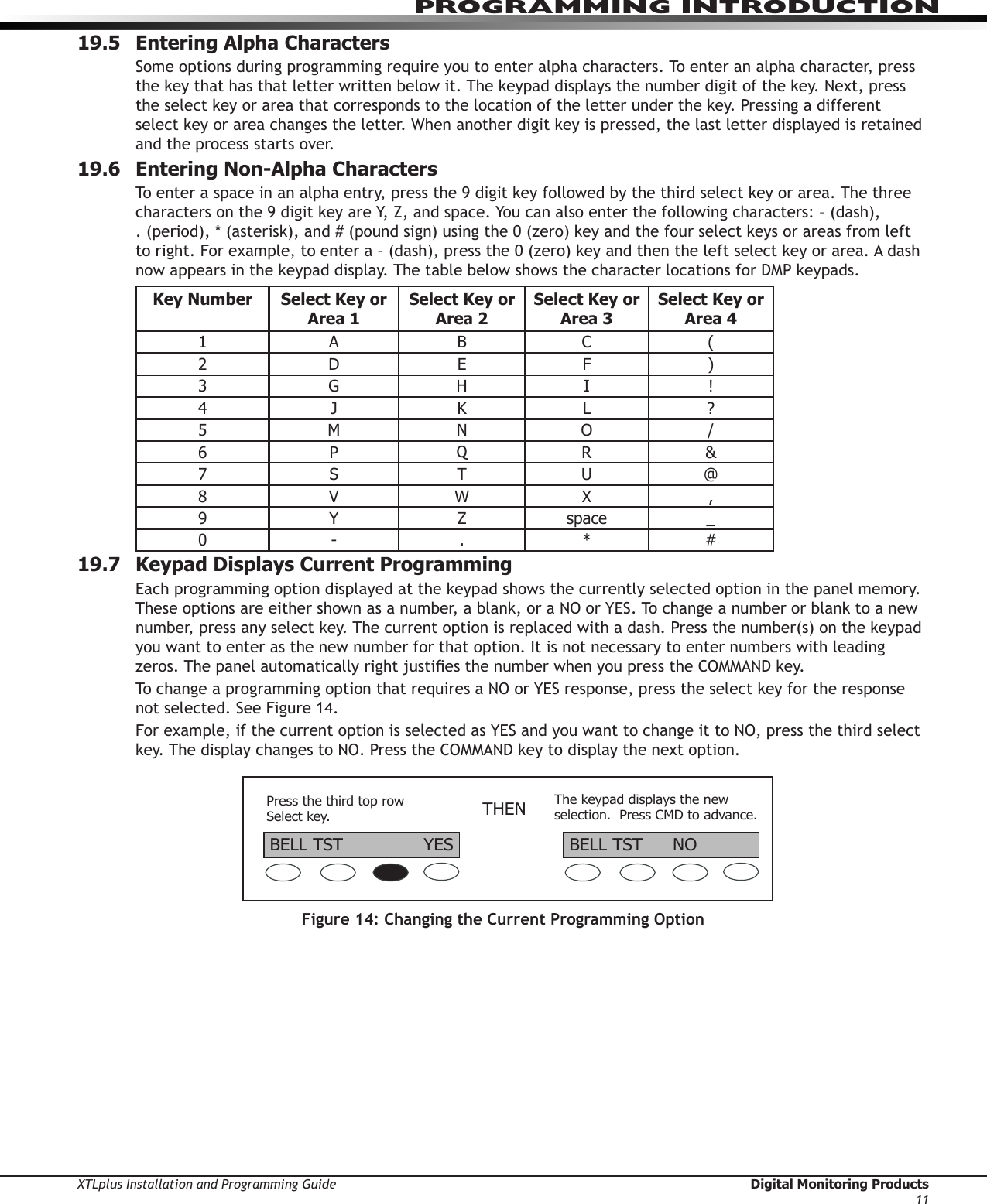
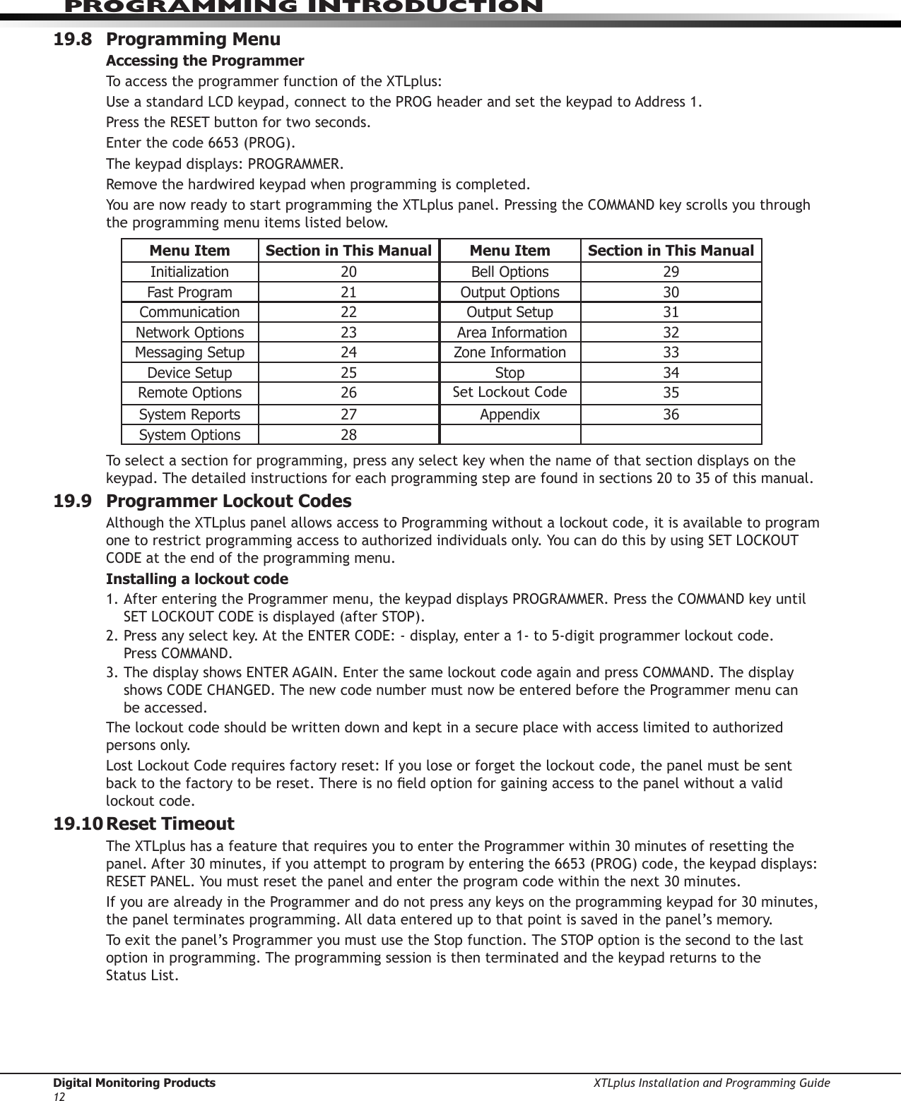
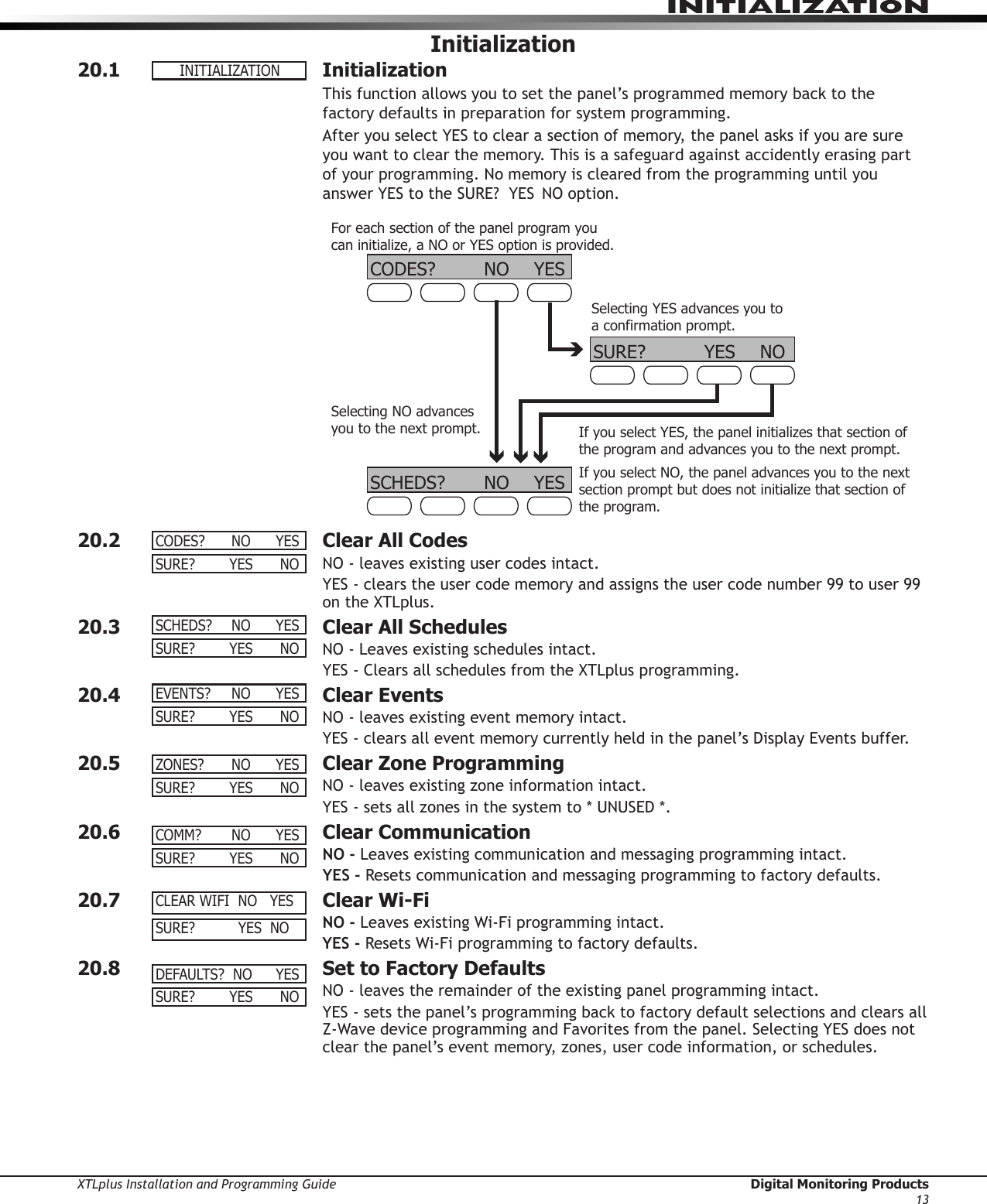
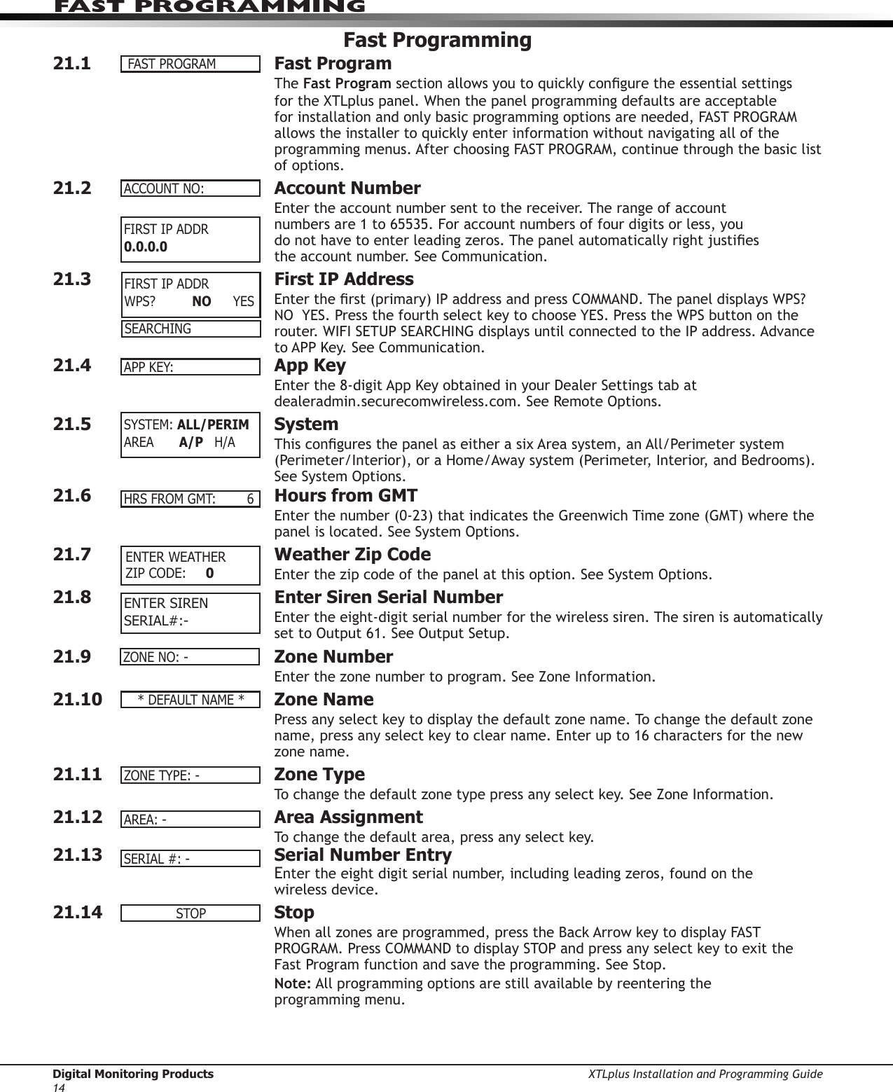
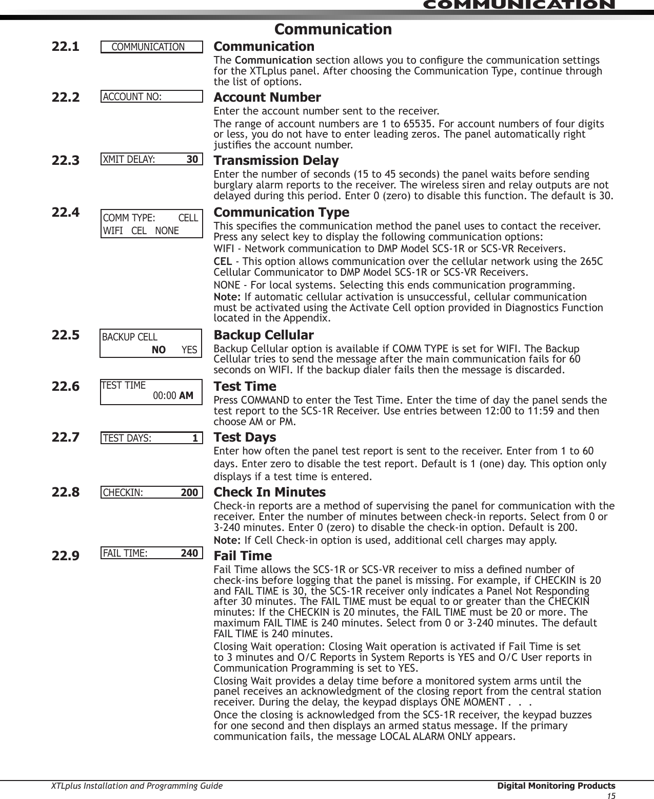
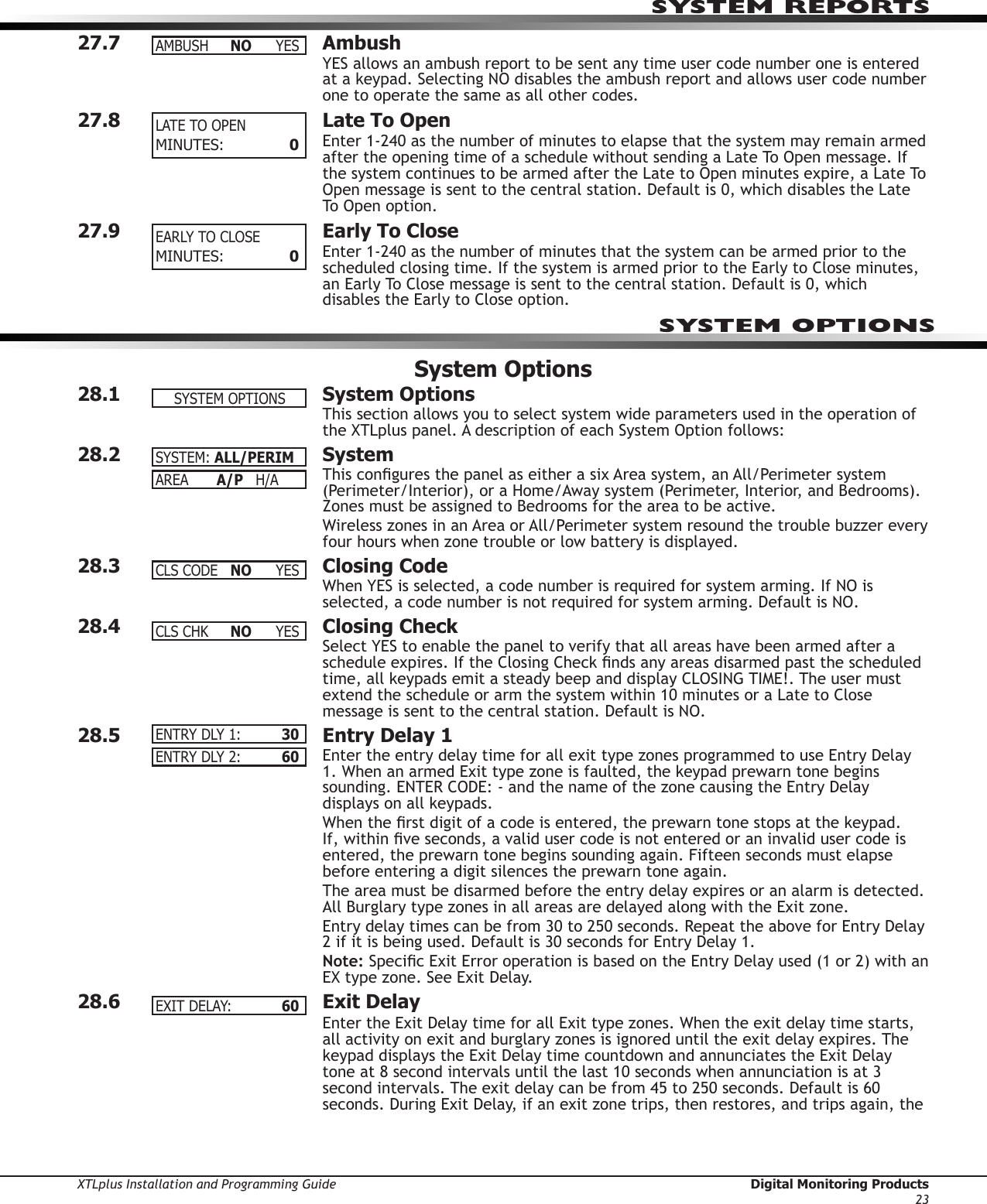
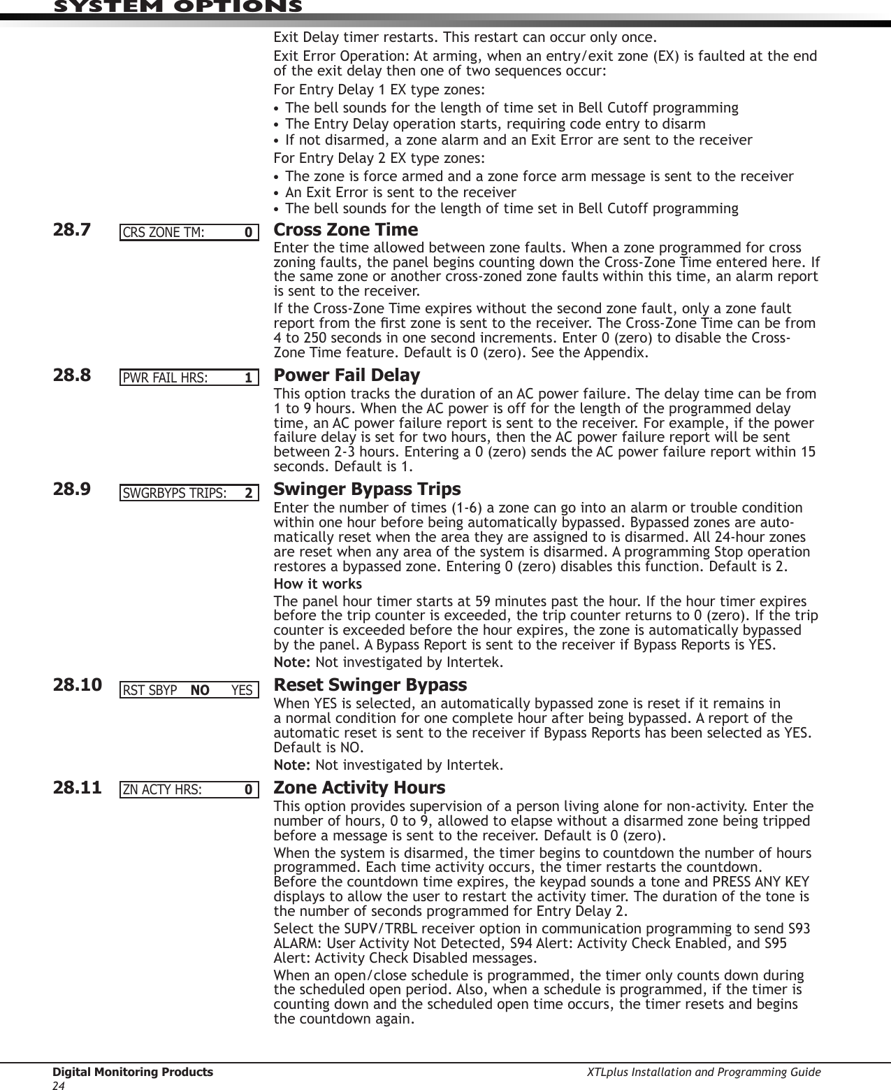
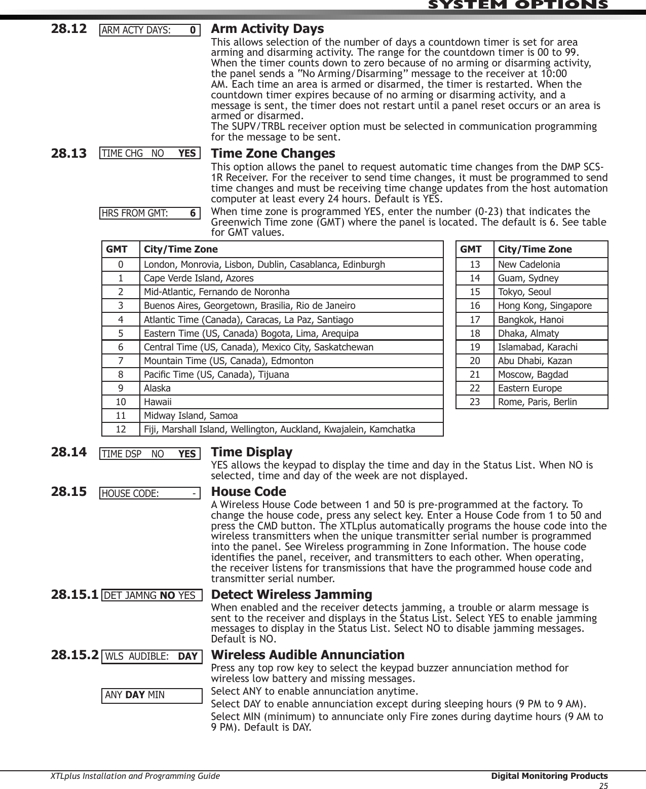
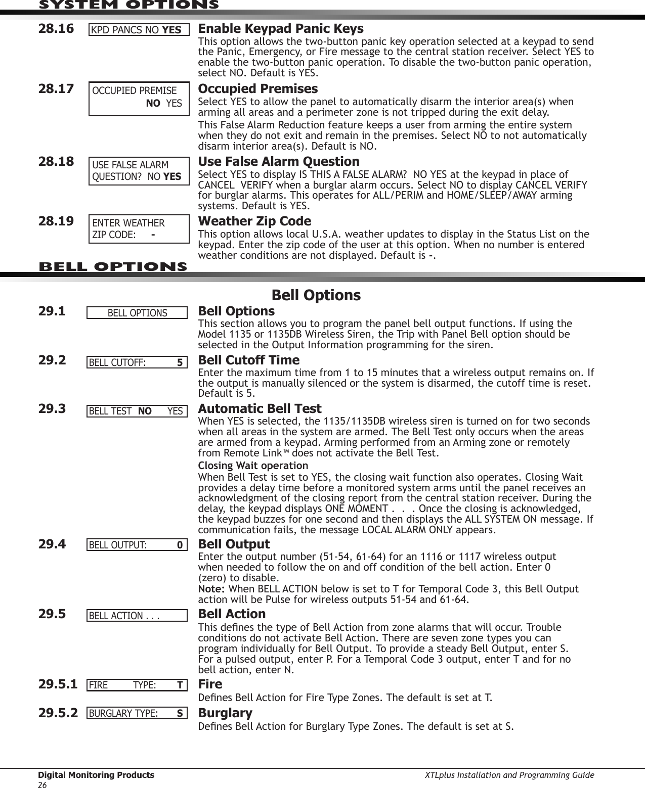
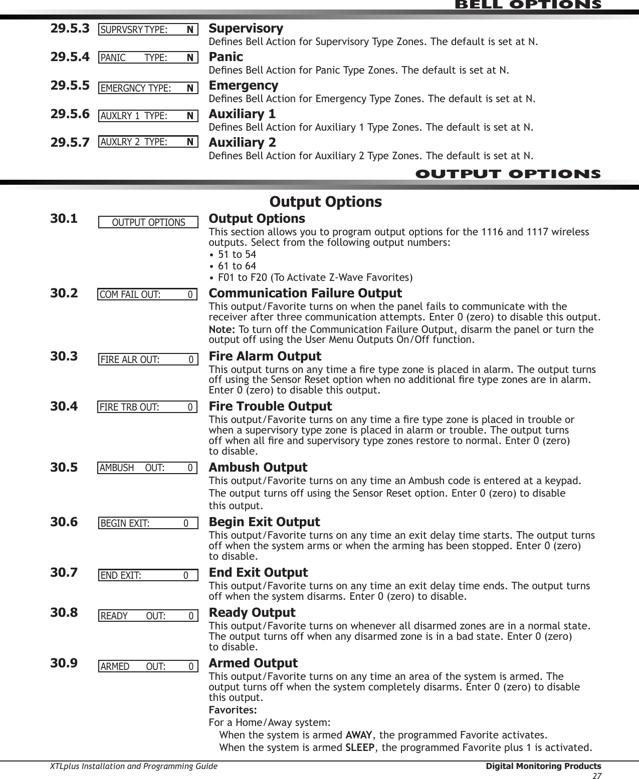
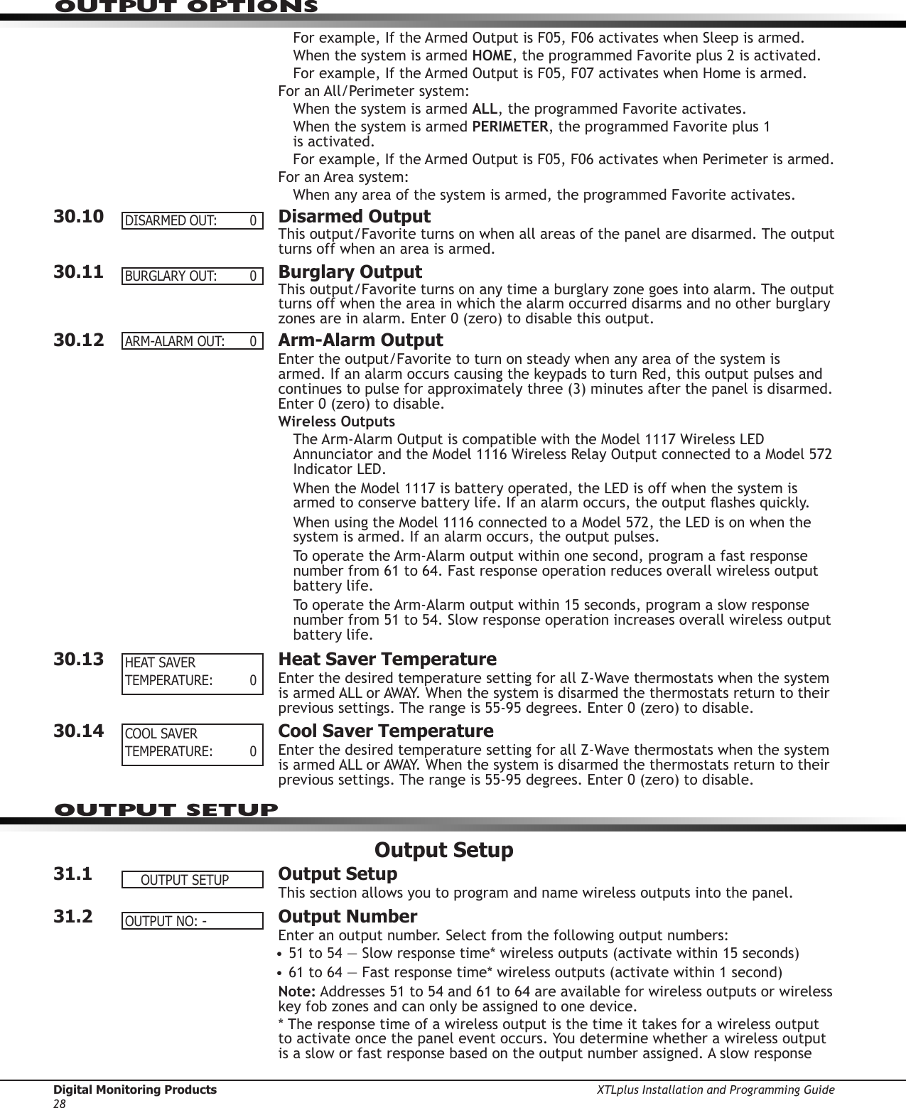
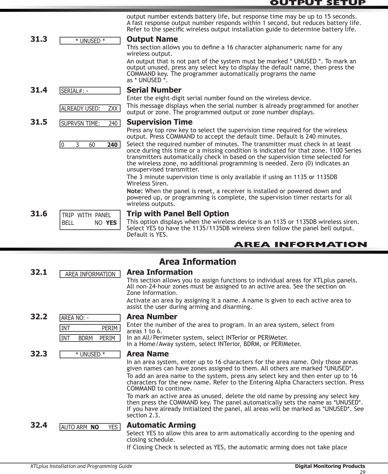
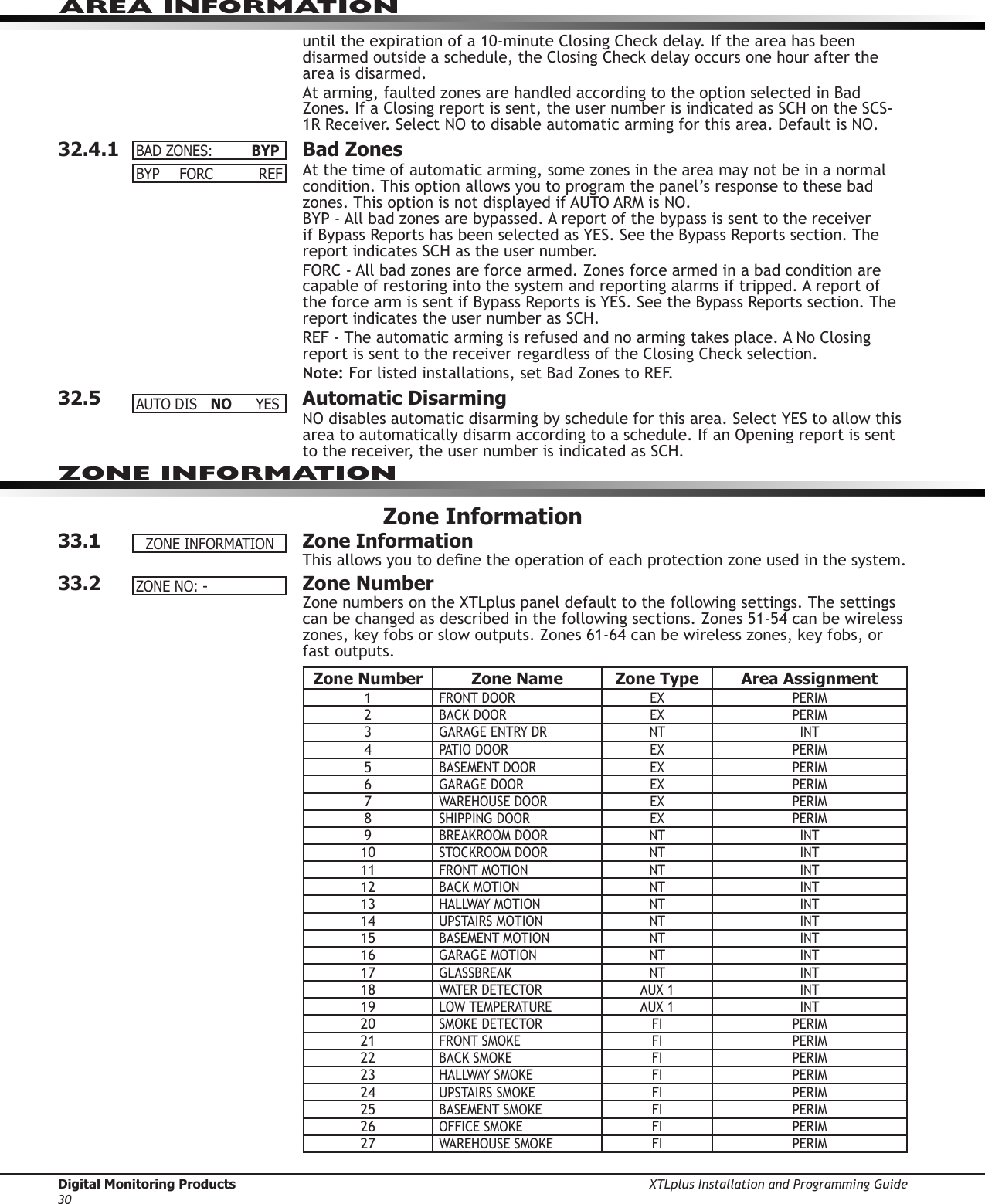
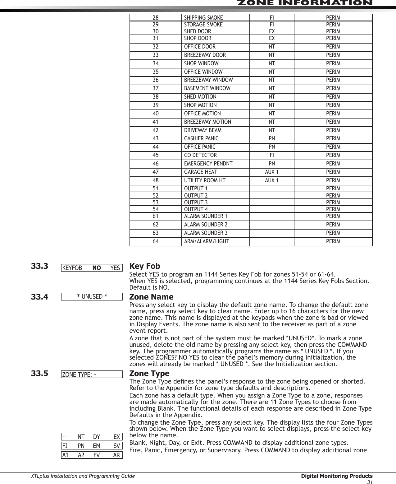
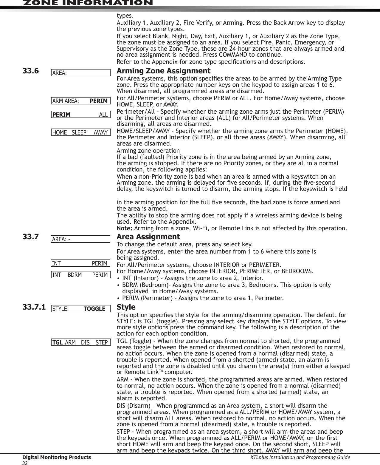
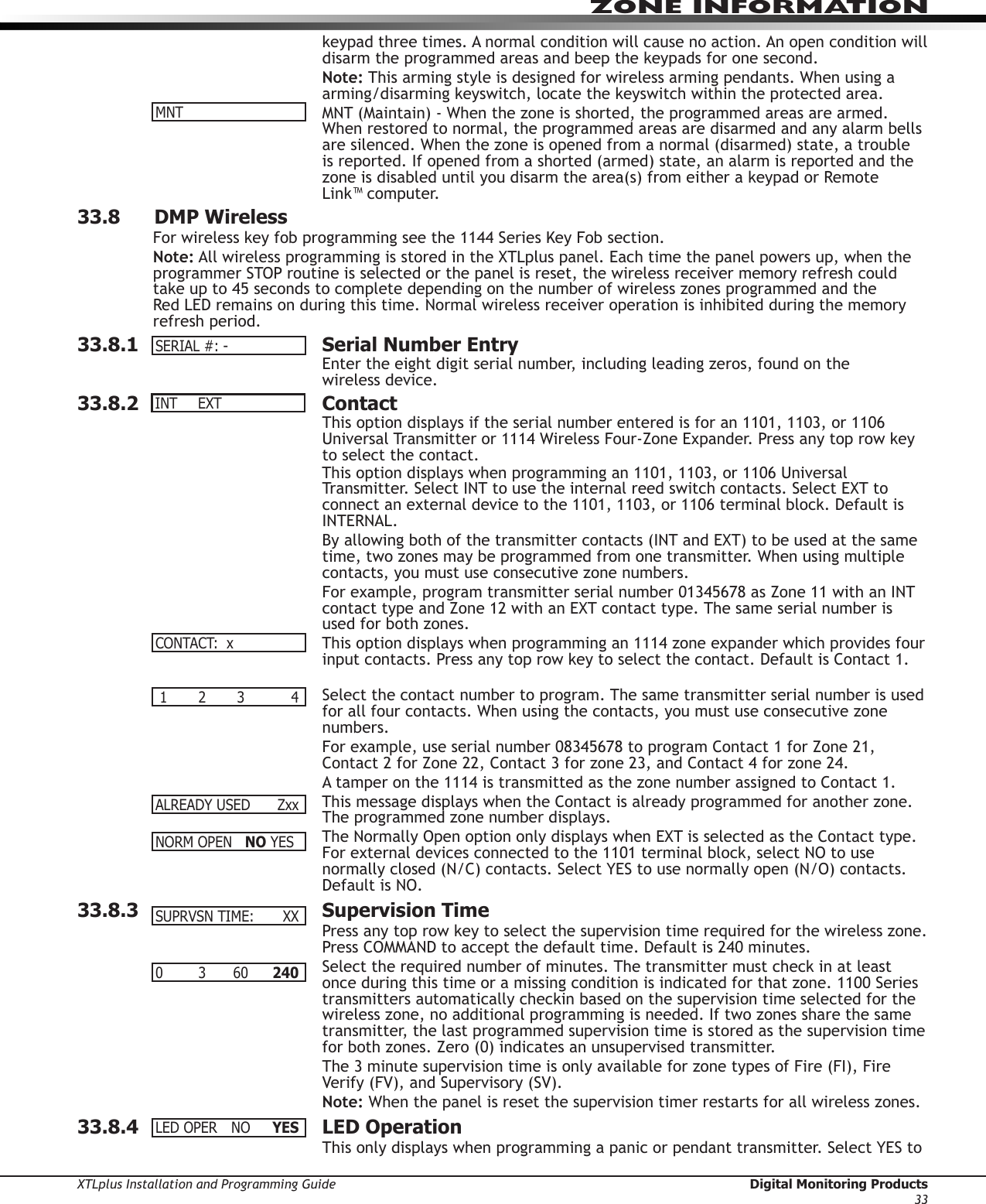
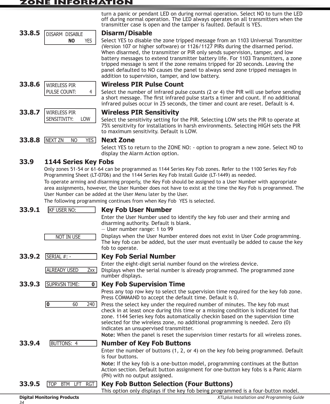
![Digital Monitoring Products XTLplus Installation and Programming Guide18NETWORK OPTIONS23.2.1 WPSWhen WPS is selected, SEARCHING displays. Press the WPS button on the Wi-Fi network router to which you are attempting to connect. SEARCHING displays for up to two minutes or until connected to the WPS enabled router. Refer to the router’s instruction manual for sending a security key to the XTLplus Series panel.If the panel fails to connect to the WPS enabled router, WPS FAILED RETRY? NO YES displays. Press the fourth select key to RETRY or press the third select key to display WPS LIST MANUAL.23.2.2 ListWhen LIST is selected, SEARCHING displays until any Wi-Fi networks are found in range. Once available Wi-Fi networks are found the keypad displays the name of the SSID (Wi-Fi Network name) and signal strength of each network. Press COMMAND to scroll through the list of available Wi-Fi networks. When the desired network is displayed, press any select key to connect.Note: If the panel is unable to detect the security type, W/L SECURITY with the default security type WPA-PSK displays. If a different security type is required, press COMMAND and WEP WPA NONE displays. Press the select key of the desired security type to choose.When connecting to the Wi-Fi network the panel also detects the security type in use and W/L KEY: *************** displays.Enter the W/L KEY and the panel performs a connection test and CONNECTING displays. When successful, CONNECTED displays on the keypad. If the panel does not connect to the Wi-Fi network, NOT CONNECTED displays. Press COMMAND to return to the WIFI SETUP main screen.23.2.3 ManualThis option allows you to enter the desired network name using the keypad. When MANUAL is selected, the current settings display. Press COMMAND to continue with no change. SecureCom is the default.Use the number keys on the keypad to enter a new or different SSID (Wi-Fi Network name), there is no need to press the select keys or areas. Once the SSID is entered, press COMMAND and SEARCHING displays.When an SSID is entered for the rst time or changed, the panel searches for the SSID entered to ensure communication. The keypad displays SSID FOUND or SSID NOT FOUND. When the SSID is found, the security type is also detected.Note: Depending on the security type, the SSID might take several seconds to process.Enter up to 32 characters for the SSID from the network router to identify the network LAN. The SSID is blank by default. Use the chart below to enter lowercase or special characters. Each successive press of the select key gives additional options. For example, to enter Me5%, you would press key # 5, select key 1 (M); press key # 2, select key 2 twice (e); press key # 5 (5); press key # 7, select key 4 twice (%).Key Number Select key 1 Select key 2 Select key 3 Select key 4Note: When \ is entered, the keypad displays ¥. When ~ is entered, -> displays.1 A, a, B, b C, c (, [, {2D, d E, e F, f ), ], }3G,g H,h I, i !, ^, ~4J, j K, k L,l ?, ", |5 M, m N, n O,o /, \, `6P, p Q, q R, r &, $7S, s T, t U,u @, %8V, v W, w X, x , =9Y, y Z, z space,: _, ;0 -, + ., ' *, < #, >While searching, SEARCHING displays on the keypad. If the panel can not connect to the desired network SSID NOT FOUND displays. Press COMMAND to return to the main menu and WPS LIST MANUAL displays. Press COMMAND again to display TEST. SEARCHING .WPSLISTMANUAL SEARCHING SIGNAL▐▐▐▐▐▐▐ HOMENET123W/LSECURITY:WPA-PSK W/LSECURITY:WEPWPANONEW/LKEY:*****************W/LKEY: - WIFISETUP ENTER SSIDWPSLISTMANUALSSID:SSIDFOUND SSID:SSIDNOTFOUND ](https://usermanual.wiki/Digital-Monitoring/PC0181/User-Guide-3016304-Page-26.png)