Digital Monitoring PC0181 Security Alarm Control Panel User Manual User Guide
Digital Monitoring Products Inc Security Alarm Control Panel User Guide
User Guide

INSTALLATION AND PROGRAMMING GUIDE
XTLPLUS SERIES PANELS

MODEL XTLPLUS SERIES
INSTALLATION AND PROGRAMMING GUIDE
FCC NOTICE
This equipment has been tested and found to comply with the limits for a Class B digital device, pursuant
to Part 15 of the FCC Rules. These limits are designed to provide reasonable protection against harmful
interference in a residential installation. This equipment generates, uses and can radiate radio frequency
energy and, if not installed and used in accordance with the instructions, may cause harmful interference
to radio communications. However, there is no guarantee that interference will not occur in a particular
installation. If this equipment does cause harmful interference to radio or television reception, which can be
determined by turning the equipment off and on, the user is encouraged to try to correct the interference
by one or more of the following measures:
• Reorient or relocate the receiving antenna.
• Increase the separation between the equipment and receiver.
• Connect the equipment into an outlet on a circuit different from that to which the receiver is
connected.
• Consult the dealer or an experienced radio/TV technician for help.
Changes or modications not expressly approved by the party responsible for compliance could void the
user’s authority to operate the equipment.
This device has been designed to operate with the integrated 1100 Series PCB antenna having a maximum
gain of 1.0 dB. Antennas having a gain greater than 1.0 dB are strictly prohibited for use with this device.
The required antenna impedance is 50 ohms.
If necessary, the installer should consult the dealer or an experienced radio/television technician
for additional suggestions. The installer may nd the following booklet, prepared by the Federal
Communications Commission, helpful:
“How to identify and Resolve Radio-TV Interference Problems.”
This booklet is available from the U.S. Government Printing Ofce, Washington D.C. 20402
Stock No. 004-000-00345-4
© 2016 Digital Monitoring Products, Inc.
Information furnished by DMP is believed to be accurate and reliable.
This information is subject to change without notice.

XTLplus Installation and Programming Guide Digital Monitoring Products
i
TABLE OF CONTENTS
Panel Specications
1.1 Power Supply ......................................................................................................... 1
1.2 Communication ...................................................................................................... 1
1.3 Keypads ................................................................................................................. 1
1.4 Number of Zones .................................................................................................... 1
1.5 EnclosureSpecications .......................................................................................... 1
Introduction
2.1 SystemCongurations ............................................................................................ 1
2.2 Caution Notes ........................................................................................................ 1
2.3 Compliance Instructions .......................................................................................... 1
System Components
3.1 Accessory Devices .................................................................................................. 2
Installation
4.1 MountingLocationInformation ................................................................................ 3
4.2 MountingtheEnclosure .......................................................................................... 3
Primary Power Supply
5.1 DC Input ................................................................................................................ 3
Secondary Power Supply
6.1 Standby Battery ..................................................................................................... 4
6.2 Replacement .......................................................................................................... 4
6.3 Battery Supervision ................................................................................................. 4
LED Operation
7.1 BacklitLogo ........................................................................................................... 5
RESET Button
8.1 Description ............................................................................................................. 5
TAMPER Button
9.1 Description ............................................................................................................ 5
PROG Programming Connection
10.1 Description ............................................................................................................. 5
On-Board 1100 Series Wireless
11.1 Wireless Antenna .................................................................................................... 5
11.2 WirelessLEDOperation ........................................................................................... 5
Wireless Zones
12.1 Description ............................................................................................................. 6
Wireless Key Fobs and Outputs
13.1 Description ............................................................................................................. 6
Flash LOAD Button
14.1 Description ............................................................................................................. 6
On-Board Z-Wave Connection
15.1 Description ............................................................................................................ 6
On-Board Wi-Fi Network
16.1 Description ............................................................................................................. 6
16.2 Wi-FiLEDs ............................................................................................................. 6
Cellular Connection
17.1 Description ............................................................................................................. 7
Wireless Keypads
18.1 MountingWirelessKeypads ..................................................................................... 7
Programming Introduction
19.1 BeforeYouBegin .................................................................................................... 8
19.2 GettingStarted ....................................................................................................... 8
19.3 Keypad .................................................................................................................10
19.4 Special Keys ..........................................................................................................10
19.5 EnteringAlphaCharacters ......................................................................................11
19.6 EnteringNon-AlphaCharacters ...............................................................................11
19.7 KeypadDisplaysCurrentProgramming ....................................................................11

Digital Monitoring Products XTLplus Installation and Programming Guide
ii
TABLE OF CONTENTS
19.8 ProgrammingMenu ...............................................................................................12
19.9 ProgrammerLockoutCodes ....................................................................................12
19.10 Reset Timeout .......................................................................................................12
Initialization
20.1 Initialization ..........................................................................................................13
20.2 Clear All Codes ......................................................................................................13
20.3 ClearAllSchedules ................................................................................................13
20.4 Clear Events ..........................................................................................................13
20.5 ClearZoneProgramming ........................................................................................13
20.6 Clear Communication .............................................................................................13
20.7 Clear Wi-Fi ............................................................................................................13
20.8 Set to Factory Defaults ...........................................................................................13
Fast Programming
21.1 FastProgram .........................................................................................................14
21.2 Account Number ....................................................................................................14
21.3 First IP Address .....................................................................................................14
21.4 App Key ................................................................................................................14
21.5 System .................................................................................................................14
21.6 Hours from GMT ....................................................................................................14
21.7 WeatherZipCode ..................................................................................................14
21.8 Enter Siren Serial Number ......................................................................................14
21.9 Zone Number ........................................................................................................14
21.10 Zone Name ...........................................................................................................14
21.11 Zone Type .............................................................................................................14
21.12 AreaAssignment ...................................................................................................14
21.13 Serial Number Entry ..............................................................................................14
21.14 Stop .....................................................................................................................14
Communication
22.1 Communication .....................................................................................................15
22.2 Account Number ....................................................................................................15
22.3 Transmission Delay ................................................................................................15
22.4 Communication Type .............................................................................................15
22.5 Backup Cellular .....................................................................................................15
22.6 Test Time ..............................................................................................................15
22.7 Test Days ..............................................................................................................15
22.8 CheckInMinutes ...................................................................................................15
22.9 Fail Time ...............................................................................................................15
22.10 Send Communication Trouble .................................................................................16
22.11 First Cell APN ........................................................................................................16
22.12 Second Cell APN ....................................................................................................16
22.13 Receiver1Programming ........................................................................................16
22.14 Alarm Reports .......................................................................................................16
22.15 Supervisory/Trouble Reports ...................................................................................16
22.16 Opening/ClosingandUserReports ..........................................................................16
22.17 Test Report ...........................................................................................................16
22.18 First IP Address .....................................................................................................16
22.19 First IP Port ...........................................................................................................16
22.20 Second IP Address .................................................................................................16
22.21 Second IP Port ......................................................................................................16
22.22 Receiver2Programming ........................................................................................17
22.23 Alarm Reports .......................................................................................................17
22.24 Supervisory/Trouble Reports ...................................................................................17
22.25 Opening/ClosingandUserReports ..........................................................................17
22.26 Test Report ...........................................................................................................17
22.27 First IP Address .....................................................................................................17
22.28 First IP Port ...........................................................................................................17
22.29 Second IP Address .................................................................................................17
22.30 Second IP Port ......................................................................................................17

XTLplus Installation and Programming Guide Digital Monitoring Products
iii
TABLE OF CONTENTS
Network Options
23.1 NetworkOptions ...................................................................................................17
23.2 Wi-Fi Setup ...........................................................................................................17
23.2.1 WPS .....................................................................................................................18
23.2.2 List .......................................................................................................................18
23.2.3 Manual .................................................................................................................18
23.2.4 Test ......................................................................................................................19
23.3 Wireless Security Type ...........................................................................................19
23.4 Wireless Network Key ............................................................................................19
23.5 DHCP....................................................................................................................19
23.6 LocalIPAddress ....................................................................................................19
23.7 Gateway Address ...................................................................................................19
23.8 Subnet Mask .........................................................................................................19
23.9 DNS Server ...........................................................................................................19
23.10 ProgrammingPort .................................................................................................19
Messaging Setup
24.1 MessagingSetup ...................................................................................................19
24.2 EnableMessaging ..................................................................................................20
24.3 System Name ........................................................................................................20
24.4 Destination 1 .........................................................................................................20
24.5 Destination1UserNumber ....................................................................................20
24.6 Destination 2 .........................................................................................................20
24.7 Destination2UserNumber ....................................................................................20
24.8 Destination 3 .........................................................................................................20
24.9 Destination3UserNumber ....................................................................................20
24.10 O/CSMS ...............................................................................................................20
24.11 MonthlyLimit ........................................................................................................20
Device Setup
25.1 Device Setup .........................................................................................................20
25.2 Device Number......................................................................................................20
25.3 Device Name .........................................................................................................21
25.4 Wireless ................................................................................................................21
25.5 Serial Number .......................................................................................................21
25.6 Supervision Time ...................................................................................................21
Remote Options
26.1 RemoteOptions ....................................................................................................21
26.2 Remote Key ..........................................................................................................21
26.3 ManufacturerAuthorization ....................................................................................21
26.4 AlarmReceiverAuthorization ..................................................................................21
26.5 ServiceReceiverAuthorization ................................................................................21
26.6 Remote Disarm .....................................................................................................22
26.7 App Key ................................................................................................................22
System Reports
27.1 System Reports .....................................................................................................22
27.2 Opening/ClosingReports ........................................................................................22
27.3 Abort Reports ........................................................................................................22
27.4 Zone Restoral Reports ............................................................................................22
27.5 Bypass Reports......................................................................................................22
27.6 CodeChangeReports ............................................................................................22
27.7 Ambush ................................................................................................................23
27.8 LateToOpen ........................................................................................................23
27.9 Early To Close .......................................................................................................23
System Options
28.1 SystemOptions .....................................................................................................23
28.2 System .................................................................................................................23
28.3 ClosingCode .........................................................................................................23
28.4 ClosingCheck ........................................................................................................23
28.5 Entry Delay 1 ........................................................................................................23

Digital Monitoring Products XTLplus Installation and Programming Guide
iv
TABLE OF CONTENTS
28.6 Exit Delay .............................................................................................................23
28.7 Cross Zone Time ...................................................................................................24
28.8 Power Fail Delay ....................................................................................................24
28.9 SwingerBypassTrips .............................................................................................24
28.10 ResetSwingerBypass ............................................................................................24
28.11 Zone Activity Hours ................................................................................................24
28.12 Arm Activity Days ..................................................................................................25
28.13 TimeZoneChanges ...............................................................................................25
28.14 Time Display .........................................................................................................25
28.15 House Code ..........................................................................................................25
28.15.1 DetectWirelessJamming .......................................................................................25
28.15.2 Wireless Audible Annunciation ................................................................................25
28.16 Enable Keypad Panic Keys ......................................................................................26
28.17 OccupiedPremises ................................................................................................26
28.18 UseFalseAlarmQuestion .......................................................................................26
28.19 WeatherZipCode ..................................................................................................26
Bell Options
29.1 BellOptions ..........................................................................................................26
29.2 Bell Cutoff Time ....................................................................................................26
29.3 Automatic Bell Test ................................................................................................26
29.4 BellOutput ...........................................................................................................26
29.5 Bell Action.............................................................................................................26
29.5.1 Fire ......................................................................................................................26
29.5.2 Burglary ................................................................................................................26
29.5.3 Supervisory ...........................................................................................................27
29.5.4 Panic ....................................................................................................................27
29.5.5 Emergency ............................................................................................................27
29.5.6 Auxiliary 1 .............................................................................................................27
29.5.7 Auxiliary 2 .............................................................................................................27
Output Options
30.1 OutputOptions ......................................................................................................27
30.2 CommunicationFailureOutput ................................................................................27
30.3 FireAlarmOutput ..................................................................................................27
30.4 FireTroubleOutput................................................................................................27
30.5 AmbushOutput .....................................................................................................27
30.6 BeginExitOutput ..................................................................................................27
30.7 EndExitOutput .....................................................................................................27
30.8 ReadyOutput ........................................................................................................27
30.9 ArmedOutput .......................................................................................................27
30.10 DisarmedOutput ...................................................................................................28
30.11 BurglaryOutput .....................................................................................................28
30.12 Arm-AlarmOutput .................................................................................................28
30.13 Heat Saver Temperature ........................................................................................28
30.14 Cool Saver Temperature .........................................................................................28
Output Setup
31.1 OutputSetup ........................................................................................................28
31.2 OutputNumber .....................................................................................................28
31.3 OutputName ........................................................................................................29
31.4 Serial Number .......................................................................................................29
31.5 Supervision Time ...................................................................................................29
31.6 TripwithPanelBellOption .....................................................................................29
Area Information
32.1 Area Information ...................................................................................................29
32.2 Area Number .........................................................................................................29
32.3 Area Name ............................................................................................................29
32.4 AutomaticArming ..................................................................................................29
32.4.1 Bad Zones .............................................................................................................30
32.5 AutomaticDisarming ..............................................................................................30

XTLplus Installation and Programming Guide Digital Monitoring Products
v
TABLE OF CONTENTS
Zone Information
33.1 Zone Information ...................................................................................................30
33.2 Zone Number ........................................................................................................30
33.3 Key Fob ................................................................................................................31
33.4 Zone Name ...........................................................................................................31
33.5 Zone Type .............................................................................................................31
33.6 ArmingZoneAssignment .......................................................................................32
33.7 AreaAssignment ...................................................................................................32
33.7.1 Style .....................................................................................................................32
33.8 DMP Wireless ........................................................................................................33
33.8.1 Serial Number Entry ..............................................................................................33
33.8.2 Contact .................................................................................................................33
33.8.3 Supervision Time ...................................................................................................33
33.8.4 LEDOperation .......................................................................................................33
33.8.5 Disarm/Disable ......................................................................................................34
33.8.6 Wireless PIR Pulse Count .......................................................................................34
33.8.7 Wireless PIR Sensitivity ..........................................................................................34
33.8.8 Next Zone .............................................................................................................34
33.9 1144 Series Key Fobs .............................................................................................34
33.9.1 KeyFobUserNumber ............................................................................................34
33.9.2 Key Fob Serial Number ...........................................................................................34
33.9.3 Key Fob Supervision Time ......................................................................................34
33.9.4 Number of Key Fob Buttons ....................................................................................34
33.9.5 Key Fob Button Selection (Four Buttons) .................................................................34
33.9.6 Key Fob Button Selection (Two Buttons) ..................................................................35
33.9.7 Button Action ........................................................................................................35
33.9.8 Button Press Time .................................................................................................35
33.9.9 Arm/Disarm Area Selection .....................................................................................35
33.9.10 OutputNumber .....................................................................................................35
33.9.11 OutputAction ........................................................................................................36
33.10 Alarm Action .........................................................................................................36
33.11 DisarmedOpen .....................................................................................................36
33.11.1 MessageToTransmit .............................................................................................36
33.11.2 OutputNumber .....................................................................................................36
33.11.3 OutputAction ........................................................................................................37
33.12 SwingerBypass .....................................................................................................37
33.13 Prewarn Address ...................................................................................................37
33.14 Entry Delay ...........................................................................................................37
33.15 Cross Zone ............................................................................................................37
33.16 Priority ..................................................................................................................38
33.17 TrafcCount .........................................................................................................38
33.18 Zone Audit Days ....................................................................................................38
33.19 ReceiverRouting ...................................................................................................38
33.20 Zone Number ........................................................................................................38
Stop
34.1 Stop .....................................................................................................................38
Set Lockout Code
35.1 SetLockoutCode ..................................................................................................39
Appendix
36.1 StatusList .............................................................................................................40
36.2 Transmission Delay ................................................................................................40
36.3 False Alarm Reduction ............................................................................................40
36.4 DiagnosticsFunction ..............................................................................................40
36.5 UsingtheWalkTest ...............................................................................................42
Walk Test ..............................................................................................................42
TripCounterForDMPWirelessCheck-inTest(WLS) .................................................43
TestEndWarning ..................................................................................................43
Failed Zones Display ..............................................................................................43

Digital Monitoring Products XTLplus Installation and Programming Guide
vi
TABLE OF CONTENTS
36.6 KeypadSpeakerOperation .....................................................................................43
36.7 CrossZoning .........................................................................................................43
36.8 Zone Type Descriptions ..........................................................................................44
36.9 Zone Type Defaults ................................................................................................45
36.10 CommonKeypadMessages ....................................................................................46
Listed Compliance Specications
37.1 Introduction ..........................................................................................................46
37.2 UseMarking ..........................................................................................................46
37.2 LocationsandWiring .............................................................................................46
37.3 NFPA 72 ...............................................................................................................46
37.4 TypesOfService ....................................................................................................46
37.5 PoliceStationPhoneNumbers ................................................................................46
37.6 Bypass Reports......................................................................................................46
37.7 SystemTesting ......................................................................................................46
37.8 FCC Notice ............................................................................................................47
Household Burglar-Alarm System Units
ANSI/UL 1023
38.1 Bell Cutoff .............................................................................................................47
38.2 Entry Delay ...........................................................................................................47
38.3 Exit Delay .............................................................................................................47
38.4 Wireless External Contact .......................................................................................47
38.5 Wireless Supervision Time ......................................................................................47
38.6 Wireless Audible Annunciation ................................................................................47
38.7 Panel location ........................................................................................................47
38.8 Test Frequency ......................................................................................................47
Central Station Burglar Alarm Units
ANSI/UL 1610
39.1 Supervision ...........................................................................................................47
39.2 Remote Disarm .....................................................................................................47
39.3 Central Station ......................................................................................................47
Household Fire Warning System
ANSI/UL 985 NFPA 72 Specications
40.1 BellOutputDenition .............................................................................................48
40.2 HouseholdSystem .................................................................................................48
40.3 Wireless Supervision Time ......................................................................................48
40.4 WirelessFireVerication ........................................................................................48
40.5 Battery Standby ....................................................................................................48
40.6 Test Frequency ......................................................................................................48
False Alarm Reduction Programmable Options
ANSI/SIA CP-01-2010
41.1 ShippingDefaultsandRecommendedProgramming .................................................49
Revisions
Certications
Ordering Information
Accessories

XTLplus Installation and Programming Guide Digital Monitoring Products
1
PANEL SPECIFICATIONS
Panel Specications
1.1 Power Supply
Model 372-500-W plug-in DC power supply
Input: 120VAC, 60 Hz
Output: 12VDC
Standby Battery: DMP 3.8VDC Lithium, 800mAh
Optional Standby Battery DMP 3.8VDC Lithium, 3500mAh
All circuits inherent power limited
1.2 Communication
Optional CDMA cellular module to send messages to DMP Model SCS-1R or SCS-VR Central Station Receivers.
Built-in Wi-Fi™ network alarm signal communication to DMP Model SCS-1R or SCS-VR Central
Station Receivers.
1.3 Keypads
You can associate up to 4 alphanumeric 9000 Series or 9862 Graphic Touchscreen Wireless Keypads.
1.4 Number of Zones
• XTLplus has 48 wireless initiating zones numbered 1-48
• Zone and Output numbers 51 to 54 and 61 to 64 can support 1144 Series Key Fobs, Output Modules,
or sirens
1.5 Enclosure Specications
The XTLplus panel ships in a plastic enclosure with a user’s guide and programming sheet.
Size Color
5.5” W x 3.75” H x 1” D White (W)
Introduction
2.1 System Congurations
The panel can be programmed to operate as any of the following system types:
• All/Perimeter system that provides one perimeter area and one interior area
• Home/Sleep/Away system that provides one perimeter, one interior, and one bedroom area. The bedroom
area provides for any protection devices the user wants disarmed during their sleeping hours and armed in
the Away mode.
• Six area system that provides areas of protection that can be independently armed or disarmed.
2.2 Caution Notes
Throughout this guide you will see caution notes containing information you need to know when installing
the panel. These cautions are indicated with a yield sign. Whenever you see a caution note, make sure you
completely read and understand its information. Failing to follow the caution note can cause damage to the
equipment or improper operation of one or more components in the system.
2.3 Compliance Instructions
For applications that must conform to a local authorities installation standard or a National Recognized
Testing Laboratory certicated system, please see the Listed Compliance Specications section near the end
of this guide for additional instructions.
INTRODUCTION

Digital Monitoring Products XTLplus Installation and Programming Guide
2
SYSTEM COMPONENTS
System Components
3.1 Accessory Devices
Cellular Communicator Cards
265C CDMA Cellular Communicator Allows you to connect the XTLplus to any compatible CDMA/SMS network.
DMP Two-Way Wireless Devices
1100R Repeater Provides additional range for wireless devices.
1101 Universal Transmitter Provides both internal and external contacts that may be used at the same time to
yield two individual reporting zones from one wireless transmitter.
1102 Universal Transmitter Provides one external contact.
1103 Universal Transmitter Provides bothinternalandexternalcontactsthatmaybeusedatthesametimetoyield
twoindividualreportingzonesfromonewirelesstransmitter.RequiresEOLresistorfor
external contact. Provides Disarm/Disable functionality.
1106 Universal Transmitter Provides both internal and external contacts that may be used at the same time to
yield two individual reporting zones from one wireless transmitter.
1107 Micro Window Transmitter* Provides survey capability for window applications.
1114 Four-Zone Expander* Provides four wireless zones with EOL resisters.
1116 Relay Output* Provides one Form C relay.
1117 LED Annunciator* Provides a visual system status indicator.
1119 Door Sounder* Provides a wireless sounder with integrated door contact.
1121 PIR Motion Detector* Provides motion detection with pet immunity.
1126R Motion Detector* Ceiling mount motion detector with panel programmable sensitivity and Disarm/
Disable functionality.
1127C/1127W PIR Motion Detector Wall mount motion detector with panel programmable sensitivity and Disarm/Disable
functionality.
1129 Glassbreak Detector* Detects the shattering of framed glass mounted in an outside wall and provides full-
pattern coverage and false-alarm immunity.
1131 Recessed Contact*
Provides concealed protection for doors, windows or other applications.
1135/1135DB Siren* Provides a wireless siren.
1137 Wireless LED Emergency Light* Provides emergency indoor path lighting.
1139 Bill Trap* Provides a silent alarm option for use in cash drawers.
1141 Wall Button* One-button wireless transmitter designed to be wall-mounted.
1142BC Two-button Panic Belt Clip
Transmitter
Provides portable two-button panic operation.
1142 Two-button Panic Transmitter
Provides permanently mounted under-the-counter two-button panic operation.
1144-4 (Four-Button)*
1144-2 (Two-Button)*
1144-1 (One-Button)*
1144-D (Two-Button)*
Key Fob transmitters designed to clip onto a key ring or lanyard.
1148 Personal Pendant Wireless emergency transmitter to be worn as a wristband or on a break-away lanyard.
1161 Residential Smoke Detector Residential smoke detector with sounder.
1162 Residential Smoke Detector Residential smoke/heat detector with sounder and xed rate-of-rise heat detector.
1164 Wireless Synchronized Smoke
Detector
Commercial or residential, battery powered, wireless, low prole, photoelectric
smoke detector, with synchronizing sounder.
1183-135F Heat Detector Fixed temperature heat detector.
1183-135R Heat Detector Fixed temperature and rate-of-rise heat detector.
1184 Carbon Monoxide Detector Carbon Monoxide detector.
Keypads
9000 Series LCD Keypads Allows you to control the panel from various remote locations.
9862 Wireless Graphic Touchscreen
Keypad
Allows you to control the panel from various remote locations.
* These devices have not been investigated and shall not be used in listed installations.
XTLplus Installation and Programming Guide Digital Monitoring Products
3
INSTALLATION
Installation
4.1 Mounting Location Information
A location should be selected that is centrally located between the 1100 Series transmitters used in the
installation. Install the XTLplus away from metal objects. Mounting the panel on or near metal surfaces
impairs performance. When selecting the proper mounting location of a transmitter, refer to the LED Survey
Operation section of the specic installation guide for the transmitter being installed.
4.2 Mounting the Enclosure
The enclosure for the panel must be mounted using the provided #6 screws in the four mounting holes shown
in Figure 1. Mount the enclosure in a secure, dry place away from metal objects to protect the panel from
damage due to tampering or the elements. Mount the panel a minimum of 4 feet from any wireless
transmitters or repeaters. It is not necessary to remove the PCB when installing the enclosure.
Figure 1: Mounting Hole Locations
Primary Power Supply
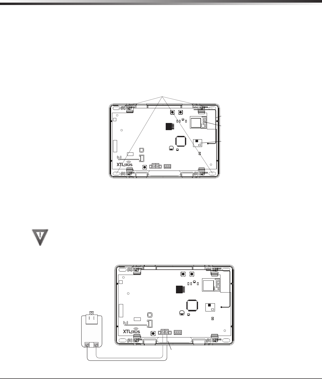
5.1 DC Input
Mount the panel near a wall outlet for the Model 372-500-W plug-in DC power supply. In addition to powering
the panel, the DC plug-in power supply also charges the back-up battery. The 372-500-W must be located
within 100 feet of the panel using 22 AWG wire. Use the following steps to connect the plug-in power supply:
OBSERVE POLARITY
1. Using 22 AWG wire, connect the panel DC terminal (+) to the positive terminal on the power supply.
2. Connect the panel DC terminal (-) to the negative terminal on the power supply. See Figure 2.
3. Plug the power supply into a 120 Volt AC, 60Hz dedicated outlet not controlled by a switch.
Figure 2: DC Power Supply Connection
Mounting Hole Locations
ZWave
Module
WiFi
Antenna
RESETLOAD
BAT
PROG
R B
+ DC -
S
N
LEV
LPC-0181
R1
INSTALL GUIDE
LT-1434
CELL
MODULE
©
2015 DMP
WWW.DMP.COM
Wire Exits for DC
Power Supply
+
Model 372-500-W
DC Plug-in
Power Supply
Use 22 AWG for
Power Supply connection
_
RESETLOAD
BAT
PROG
R B
+ DC -
S
N
LEV
LPC-0181
R1
INSTALL GUIDE
LT-1434
CELL
MODULE
©
2015 DMP
WWW.DMP.COM
Digital Monitoring Products XTLplus Installation and Programming Guide
4
INSTALLATION
Secondary Power Supply
6.1 Standby Battery
The XTLplus 800mAh rechargeable battery is used to provide 4 hours of standby battery power when DC
power is not available. The battery is intended for backup power only and not to operate the panel on a
daily basis. If the battery is low, or not plugged into the BAT battery connector, a low battery condition
is indicated by the panel. If 24 hour standby battery power is needed, connect the 3500mAh battery. See
Figure 3.
Note: If removing the panel from service, disconnect the backup battery from the BAT connector.
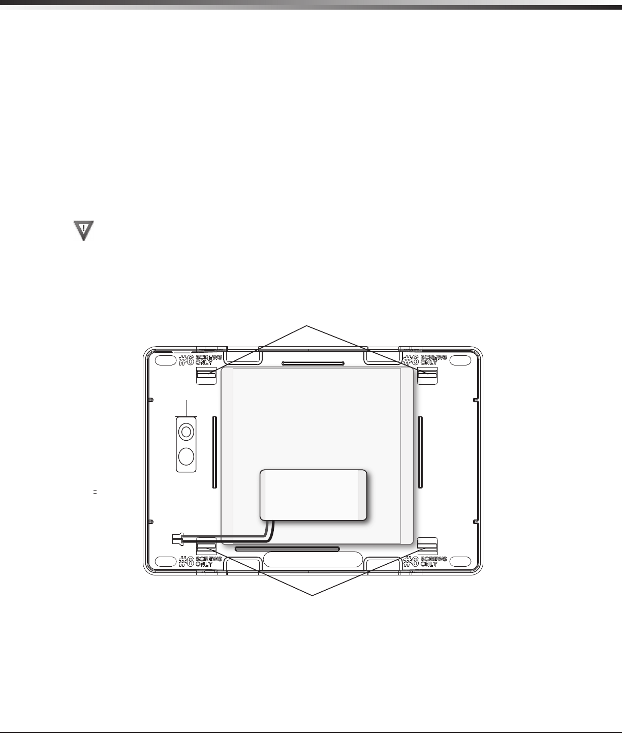
6.2 Replacement
Use the following steps to replace the XTLplus standby battery. DMP recommends replacing the battery every
3 years under normal use.
1. Unplug the BAT battery connector from the XTLplus panel.
2. Loosen the top PCB snaps.
3. Lean the panel PCB forward and lift out from the bottom PCB snaps.
4. Remove and properly dispose of the used battery.
Caution: Risk of re, explosion, and burns. Do not disassemble, heat above 212°F (100°C), or
incinerate. Properly dispose of used batteries.
5. Place the new battery into the XTLplus housing base with the battery wires directed toward the bottom
left corner. See Figure 3.
6. Set the XTLplus PCB into the bottom snaps and press into the top snaps to secure in place.
7. Plug the battery into the BAT panel connector.
6.3 Battery Supervision
The panel tests the battery once every hour when DC power is present. This test occurs 15 minutes past
each hour and lasts for ve seconds. A load is placed on the battery and if the battery voltage is low, a low
battery is detected. If DC power has failed, a low battery is detected any time the battery voltage falls
below 3.7V.
Top PCB Snaps
Bottom PCB Snaps
Battery
Connector
3.8V 3500mAh Rechargeable Battery
(required for 24 hour standby)
3.8V 800mAh
Rechargeable
Battery
Figure 3: Standby Battery Replacement
XTLplus Installation and Programming Guide Digital Monitoring Products
5
INSTALLATION
LED Operation
7.1 Backlit Logo
The backlit logo indicates the Power and Armed status of the panel. Depending on the operation, the LED
displays in Red or Green as listed in the table.
Color and Activity Operation
Green Steady Panel Disarmed, Primary Power OK, Battery OK
Green Blinking Panel Disarmed, Primary Power OK, Battery Fault
No Light Panel Disarmed, Primary Power Fault, Battery OK
Red Steady Panel Armed, Primary Power OK, Battery OK
Red/Green Alternate Panel Armed, Primary Power OK, Battery Fault
Red Blinking Panel Armed, Primary Power Fault, Battery OK
RESET Button
8.1 Description
The RESET button is located on the top of the circuit board and is used to reset the XTLplus microprocessor.
To reset the panel prior to reprogramming, press the RESET button without powering down the system. After
resetting the panel, begin programming within 30 minutes. If you wait longer than 30 minutes, you must
reset the panel again. See Figure 5 for RESET button location.
TAMPER Button
9.1 Description
The tamper button is pressed when the cover of the XTLplus is secured onto the enclosure. When the cover
is removed, the XTLplus sends a Tamper Trouble message to the Central Station. See Figure 4 for TAMPER
button location.
PROG Programming Connection
10.1 Description
Onsite programming can be completed using an associated wireless keypad or by connecting a hardwired
keypad to the PROG header.
On-Board 1100 Series Wireless
11.1 Wireless Antenna
The XTLplus Wireless Antenna is integrated into the circuit board. The panel’s built-in wireless receiver
operates with DMP 1100 Series transmitters. See section 3.1 for a list of accessory devices.
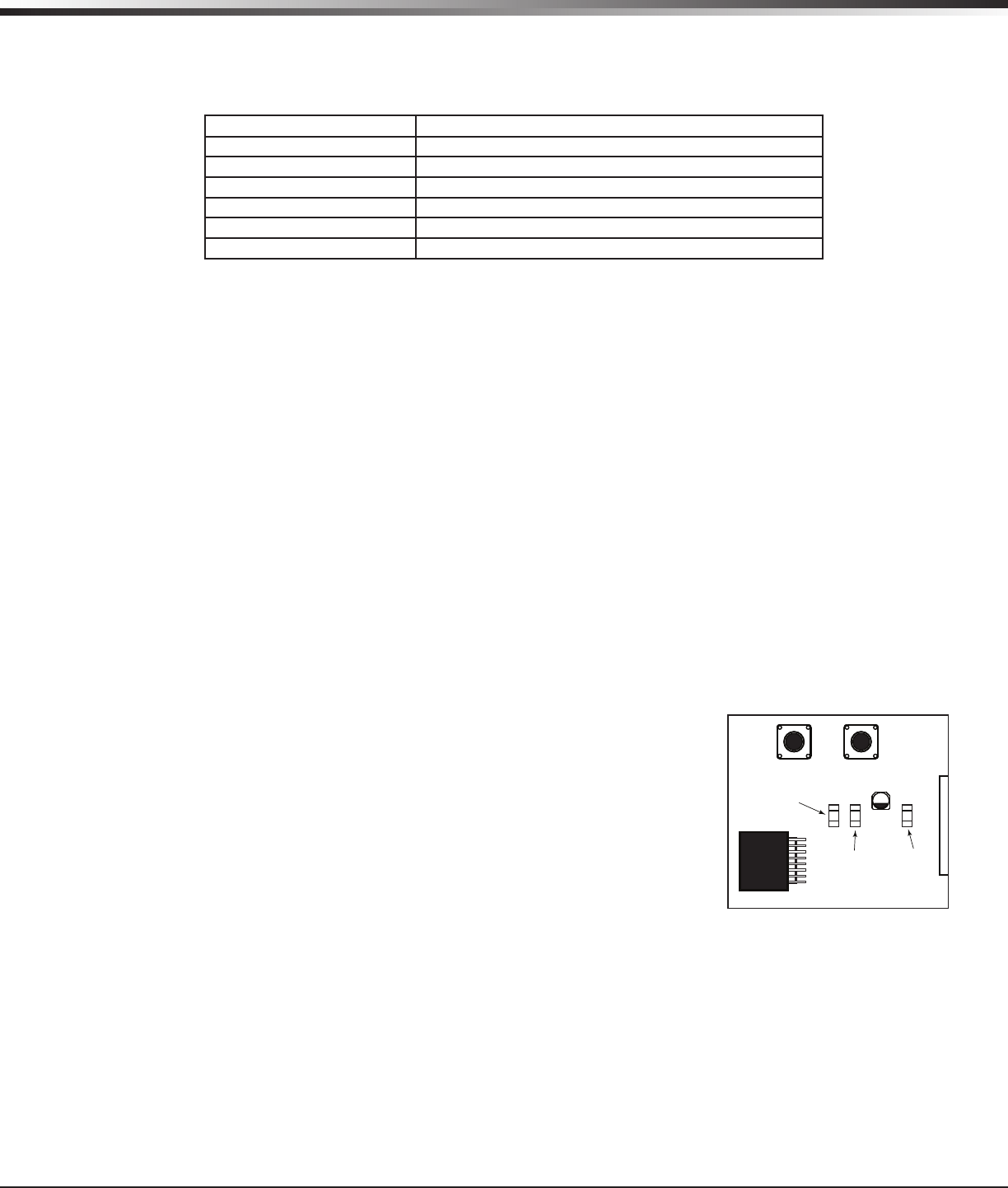
11.2 Wireless LED Operation
The wireless LEDs are located in the upper right of the circuit board below
the RESET button and
function as follows:
Green: The green LED ashes every time the receiver transmits (32 times
per second). If the panel is reset, or the panel is powered off, the green
LED is off. Under normal operation, the green LED ashes constantly with no
interruption or change.
Yellow: The yellow LED ashes every time the panel receives a message from
a programmed wireless transmitter. When a message is sent by a transmitter,
typically by pressing or releasing the TAMPER button, the yellow LED should
ash indicating that the panel received a message from the transmitter.
If the LED never ashes, the transmitter is not getting through to the panel. This could be because of a
misprogrammed serial number or the transmitter is too far away. Under normal operation, the yellow
LED ashes at every trip of every wireless transmitter and when the transmitters perform their periodic
check-in. It is not unusual for this LED to stay off for many minutes at a time when no transmitters are
communicating. See Figure 5 for Wireless LED locations.
RESETLOAD
XTL PLUS
BAT
PROG
R B
+ DC -
S
N
LEV
LPC-0181
R1
INSTALL GUIDE
LT-1434
CELL
MODULE
©
2015 DMP
WWW.DMP.COM
Red LED
Green LED
Green
Transmit
LED
Yellow
Receive
LED
WiFi
LED
TAMPER
Button
Figure 5: XTLplus Wireless
LED’s

Digital Monitoring Products XTLplus Installation and Programming Guide
6
INSTALLATION
Wireless Zones
12.1 Description
XTLplus panels provide 48 wireless zones numbered 1 to 48. A default zone name, zone type, and area
assignment are described and can be changed in Zone Information programming as needed. The defaults are
provided as a programming convenience to help reduce installation time.
Wireless Key Fobs and Outputs
13.1 Description
XTLplus panels provide 8 wireless key fob or output addresses numbered 51 to 54 and 61 to 64. A default
name is provided as a programming convenience to help reduce installation time. The default names are
described in the programming sections of this guide and can be changed in Output Information or Zone
Information programming as needed
Flash LOAD Button
14.1 Description
The XTLplus panel software can be updated via the panel’s PROG programming header. To update the panel
with a new software version, complete the following steps at the protected premises:
Model 399 Cable
Connect a DMP 399 Cable from the PROG header to the serial port of your PC operating Remote Link and
containing the XTLplus RU le.
1. Start Remote Link and create or open the control panel account that matches the panel to be updated.
2. Set the Connection Information Type to Direct with a baud rate of 38400 and choose the appropriate
COM port.
3. Select Panel>Remote Update, then select the correct RU le for the panel.
4. Press and hold the LOAD button, then press and release the RESET button.
5. Release the LOAD button and click <Update> in Remote Link.
6. After the software update is completed, remove the 399 cable and press the RESET button to resume
normal panel operation.
Model 400 USB Flash Module
1. Press and hold the LOAD button. While holding the LOAD button, press and release the RESET button
2. Release the LOAD button.
3. Connect the USB ash drive to the Model 400 and connect the assembly to the panels PROG header. The
LED on the Model 400 will ash and display steady green.
4. Press and release the LOAD button on the Model 400 to initiate the rmware update. The LED on model
400 will ash slowly. If the LED displays fast ashes it means the rmware update was unsuccessful.
5. The update will take approximately 4.5 minutes and when complete the LED on the Model 400 will display
steady green.
6. Press and release the RESET button then remove the USB ash drive and Model 400 assembly. For
additional information see Model 400 USB Flash Module Installation Guide (LT-1402).
On-Board Z-Wave Connection
15.1 Description
The XTLplus features an on-board Z-Wave controller that allows short range radio control of Z-Wave devices
that you or your installation company may provide such as; lighting control modules, thermostat controls,
doors, and garage doors. Z-Wave Setup allows you to program the system to control the Z-Wave devices
from Smartphones using the DMP Virtual Keypad App or with the Virtual Keypad Browser. The available setup
options are: Add, List, Remove, Favorites, Transfer and Optimize.
On-Board Wi-Fi Network
16.1 Description
The XTLplus connects directly to a Wi-Fi network for TCP communication using a Wireless-B/G connection.
The XTLplus uses wireless 802.11b/g Wi-Fi technology.
16.2 Wi-Fi LEDs
The Green Wi-Fi LED is located to the right of the wireless LEDs in the upper right of the circuit board.
Wi-Fi LED displays solid when the network is connected and is off when there is no network connectivity. See
Figure 5 for Wi-Fi LED location.
XTLplus Installation and Programming Guide Digital Monitoring Products
7
INSTALLATION
Cellular Connection
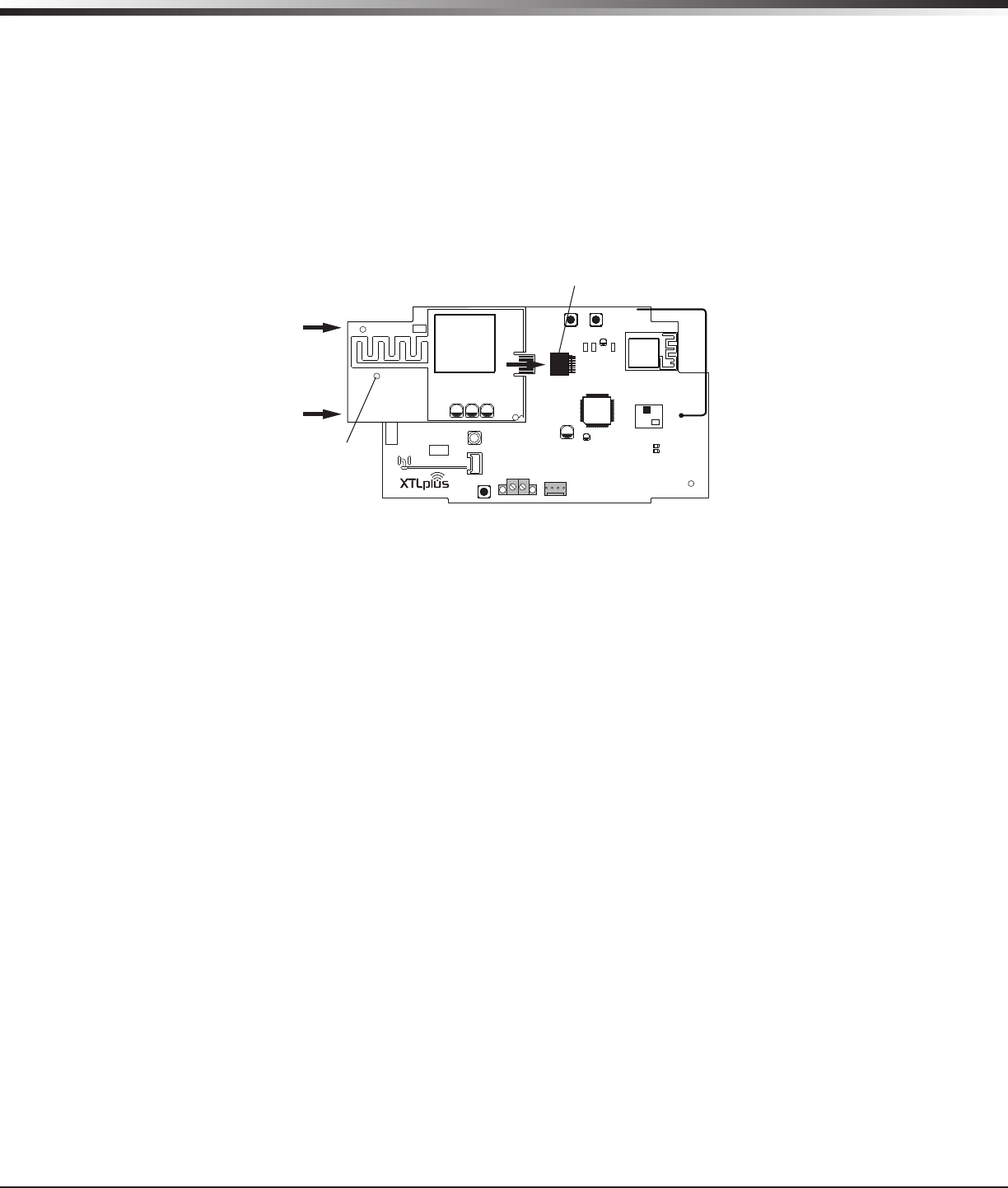
17.1 Description
The CELL MODULE header is provided to connect a 265C CDMA Cellular Communicator. The 265C provides
an integrated PCB antenna. Refer to the 265C Cellular Communicator Installation Guide (LT-1450) complete
installation information.
Installing the 265C on the XTLplus:
1. Avoiding a sharp angle and keeping the 265C PCB parallel to the XTLplus PCB, slide the 265C PCB into the
XTLplus 8-pin CELL MODULE connector. Apply even pressure to the end of the 265C PCB to fully seat the
module. See Figure 6.
2. Align the standoff hole in the 265C with the standoff on the XTLplus PCB and snap in place.
Wireless Keypads
18.1 Mounting Wireless Keypads
DMP Wireless keypads have removable covers that allow the base to be mounted on a wall, desk stand or
other at surface using the screw holes provided on each corner.
8-pin CELL MODULE
Connector
RESETLOAD
BAT
PROG
R B
+ DC -
S
N
LEV
LPC-0181
R1
INSTALL GUIDE
LT-1434
CELL
MODULE
©
2015 DMP
WWW.DMP.COM
LEV
MODEL 265C
Stando
Hole
Figure 6: 265C Installed on the XTLplus
Digital Monitoring Products XTLplus Installation and Programming Guide
8
PROGRAMMING INTRODUCTION
Programming Introduction
19.1 Before You Begin
Before starting to program, we recommend you read through the contents of this manual. The information in
this document allows you to quickly learn the programming options and operational capabilities of the
XTLplus panel.
After this Introduction, the remaining sections describe the functions of each of the programming menu
items along with their available options. The panel contains all of its programming information in an on-
board processor and does not require an external programmer.
In addition to this manual, you should also be familiar with the following XTLplus documents:
• XTLplus User’s Guide
• XTLplus Fast Programming Sheet
• XTLplus Programming Sheet
Programming Information Sheet
Included with each XTLplus panel is the Programming Sheet. This sheet lists the various options available
for programming the panel. Before starting, completely ll out the sheet with the programming options you
intend to enter into the panel.
Having completed programming sheets available while entering data helps to prevent errors and can shorten
the length of time you spend programming. Completed sheets also provide you with an accurate account of
the panel’s program you can keep on le for future system service or expansion.
The remainder of the Introduction explains starting and ending a programming session.
19.2 Getting Started
Ground Yourself Before Handling the Panel! Touch any grounded metal before touching the panel to
discharge static.
The panel should be completely installed before you begin programming. Make sure the AC and battery wires
are correctly installed.
Initializing the Panel
When programming an XTLplus panel for the rst time or rewriting the entire program of an existing
XTLplus, use the Initialization function described in section 20. Initializing clears the panel’s memory of any
old data and sets the highest numbered user number to user code 99.
Program from a Wireless or LCD Keypad
The panel can be programmed using a wireless keypad that has been auto paired or manually associated
with the panel. You can also program the panel using an LCD keypad connected to the panel PROG header.
Auto WPS
The panel offers a convenient way to connect to a Wi-Fi network. Press the WPS button on your router
within 5 minutes of powering the panel to automatically connect to the Wi-Fi network.
Wireless Keypad Auto Pairing
Wireless keypad auto pairing allows you to skip the Wireless Keypad Association process and automatically
connect your keypad to the panel. Auto pairing is only available for 9800 Series Wireless Graphics
Touchscreen Keypads (Version 109 or higher) that do not have a previously assigned house code. A maximum
of four wireless keypads are allowed on each panel.
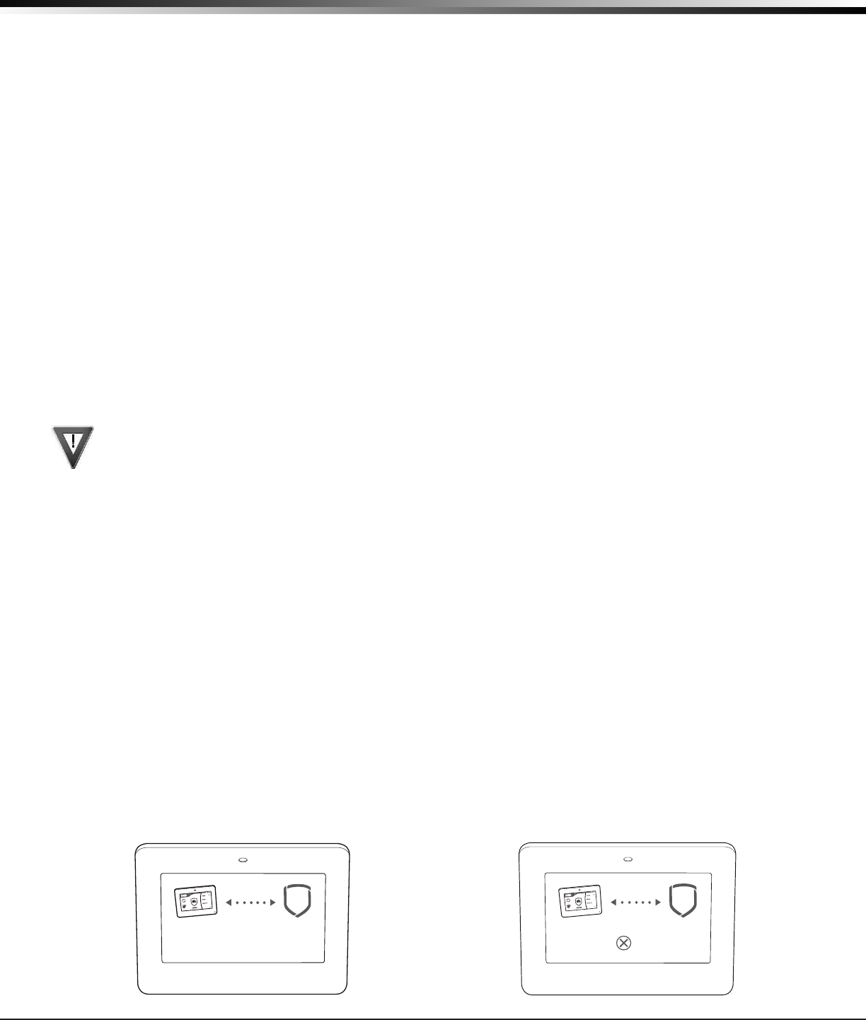
To pair a 9800 Series keypad with an XTLplus panel, power up both the panel and the keypad. A 10 minute
pairing timer begins. The auto pairing process starts immediately and the keypad displays Pairing Keypad
With System. See Figure 7. If the panel acquires the keypad during that time, the home screen displays
signaling that pairing is complete.
TODAY
WEDNESDAY
82
98 77
HI LO
CURRENT
98 77
HI LO
Pairing Keypad With System...
Figure 7: Auto Pairing in Progress Display
TODAY
WEDNESDAY
82
98 77
HI LO
CURRENT
98 77
HI LO
PAIRING FAILED
Figure 8: Auto Pairing Failed Display
XTLplus Installation and Programming Guide Digital Monitoring Products
9
PROGRAMMING INTRODUCTION
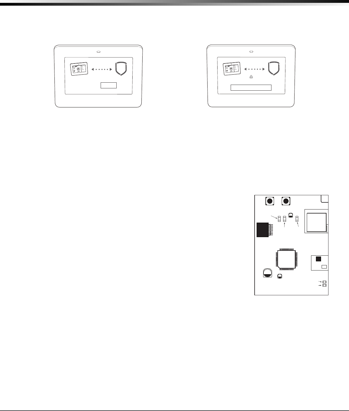
If the panel does not acquire the keypad by the end of the 10 minute pairing timer, the keypad displays
Pairing Failed, followed by the Reset screen. See Figure 8 and Figure 9. Reset your panel and tap the Pair
button to restart the pairing process.
If the keypad loses communication with the panel, the No Communication With System display appears and
provides the option to reattempt pairing. See Figure 10.
Wireless Keypad Association
To enable wireless keypad association operation on a LCD Wireless keypad, press and hold the Back Arrow
key and CMD until SET BRIGHTNESS displays. Enter the code 3577 (INST) and press CMD. Press KPD RF to start
the RF survey communication. The keypad displays its wireless serial number and RF SURVEY.
To enable association operation on a Wireless Graphics Touchscreen keypad, access the Options menu
through the carousel menu. While in the Options display, press the Installer Options icon. Enter the code
3577 (INST) and press CMD. Press KPD RF to start the RF survey communication. The keypad displays its
wireless serial number and RF SURVEY.
The keypad Power/Armed LED turns Red, indicating communication has not yet been established with the
panel receiver.
To enable association operation in the XTLplus Series panel, press the XTLplus
Series RESET button three times allowing the wireless TRANSMIT LED (TX)
located near the top of the PCB to begin ashing between each press. When
in keypad association, the XTLplus Series Red and Green logo LEDs turn on
steady.
For 60 seconds, the panel listens for wireless keypads that are in RF Survey
and have not been programmed, or associated into another panel. Wireless
keypads are assigned to the rst open device position in Device Setup
automatically, based upon the order in which they are detected. When
successful communication has been established, the Power/Armed LED turns
Blue on Graphics keypads or Green on LCD keypads.
Note: A maximum of four wireless keypads are allowed on each panel.
See the 9000 Series Wireless Keypad Installation Guide (LT-1107) or 9862
Graphic Touchscreen Wireless Keypad Installation Guide (LT-1367) for
additional information.
RESETLOAD
XTL PLUS
BAT
PROG
R B
+ DC -
S
N
LEV
LPC-0181
R1
INSTALL GUIDE
LT-1434
CELL
MODULE
©
2015 DMP
WWW.DMP.COM
Red LED
Green LED
Green
Transmit
LED
Yellow
Receive
LED
WiFi
LED
TAMPER
Button
Figure 11: XTLplus Backlit
Logo LED’s
TODAY
WEDNESDAY
82
98 77
HI LO
CURRENT
98 77
HI LO
Reset your
System.
Press button:
PAIR
2
1
Figure 9: Auto Pairing Reset Display
TODAY
WEDNESDAY
82
98 77
HI LO
CURRENT
98 77
HI LO
?
No Communication With System
Press To Pair With System
!
Figure 10: Auto Pairing No Communication Display
Digital Monitoring Products XTLplus Installation and Programming Guide
10
PROGRAMMING INTRODUCTION
19.3 Keypad
Associate up to four DMP 9060, 9062 Wireless LCD Keypads or 9862 Graphic Touchscreen Wireless Keypads to
the XTLplus panel. The operation is shown and described in the following sections.
19.4 Special Keys
The following special keys or areas are common to all DMP keypads.
COMMAND (CMD) Key
Pressing the COMMAND key allows you to go forward through the programming menu and through each
step of a programming sec tion. As you go through the programming, the keypad display shows any current
programming already stored in the panel memory. If no change is required for an option, press the COMMAND
key to advance to the next step.
The COMMAND key is also used to enter information into the panel’s memory such as phone numbers or zone
names. Press the COMMAND key after entering information.
Back Arrow (<—) Key
Use the Back Arrow key to back up one step while programming. The Back Arrow key is also used when an
error is made while entering in formation. Press the Back Arrow key once to erase the last character entered.
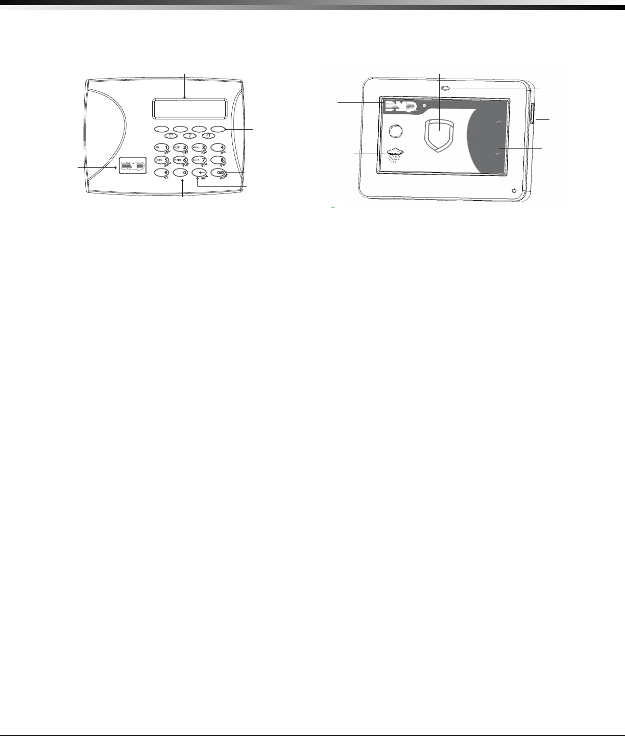
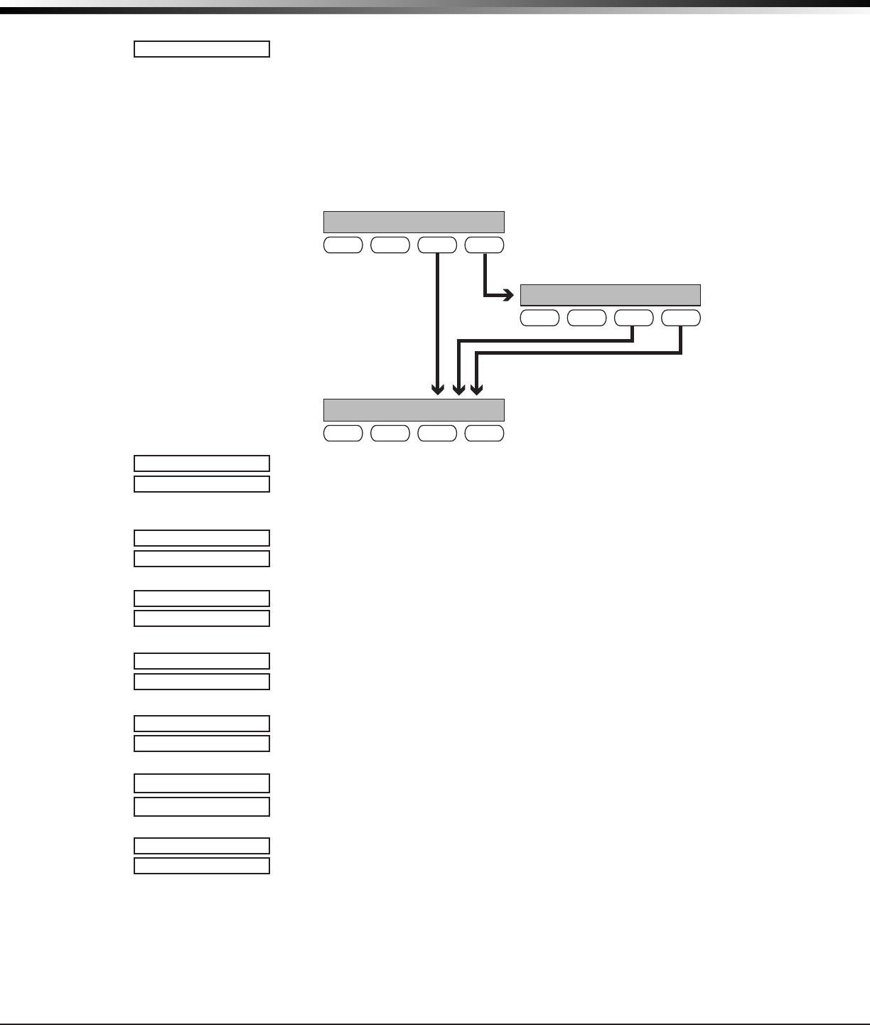
Select Keys or Areas
The top row of keys are called the select keys on Thinline and Aqualite keypads or select areas on Graphic
Touchscreen keypads. Each time you need to press a select key or area, the keypad displays the function or
options above one of the keys or in the select areas. Displaying choices above individual select keys or in
select areas allows them to be used for many different applications. For example, you can enter AM or PM
when programming the automatic test time or answer YES or NO for a system option.
During programming, the select keys allow you to change infor mation currently in panel memory by pressing
the appropriate select key under the display. You then enter the new information using the keypad data
entry digit keys.
When there are more than four re sponse options avail able, press the COMMAND key to display the remaining
options. Pressing the Back Arrow key allows you to review the previous four choices.
The select keys are also used for choosing a section from the pro gramming menu. When the programming
section name you want displays, press any select key.
On Wireless, Thinline and Aqualite keypads, when instructed to press the rst select key, press the far left
select key; the second select key is the second from the left; third select key is second from the right; and
the fourth select key is the far right key. See Figure 12.
On Graphic Touchscreen Keypads, when instructed to press the rst select key, touch select area 1; the
second select key touch select area 2; third select key touch select area 3; and the fourth select key touch
select area 4. See Figure 13.
Figure 13: 9862 Graphic Touchscreen Keypad
MON 5:35 AM
DISARMED
Panic
Chime
Check-In
Reset
Interactive Shield
Proximity Card
Reader
Micro SD
Card Slot
Carousel
Menu
Dealer
Logo
Local Weather
Conditions
TODAY
WEDNESDAY
82
98 77
80
LO
74
HI
HI LO
CURRENT
32-Character Display
Data Entry Digit keys
COMMAND Key
Back Arrow Key
Select Keys
Backlit Logo
and Proximity
Antenna
Figure 12: 9000 Series Wireless Keypad
XTLplus Installation and Programming Guide Digital Monitoring Products
11
PROGRAMMING INTRODUCTION
19.5 Entering Alpha Characters
Some options during programming require you to enter alpha characters. To enter an alpha character, press
the key that has that letter written below it. The keypad displays the number digit of the key. Next, press
the select key or area that corresponds to the loca tion of the letter under the key. Pressing a different
select key or area changes the letter. When an other digit key is pressed, the last letter displayed is retained
and the process starts over.
19.6 Entering Non-Alpha Characters
To enter a space in an alpha entry, press the 9 digit key followed by the third select key or area. The three
characters on the 9 digit key are Y, Z, and space. You can also enter the following characters: – (dash),
. (period), * (asterisk), and # (pound sign) using the 0 (zero) key and the four select keys or areas from left
to right. For example, to enter a – (dash), press the 0 (zero) key and then the left select key or area. A dash
now appears in the keypad display. The table below shows the character locations for DMP keypads.
Key Number Select Key or
Area 1
Select Key or
Area 2
Select Key or
Area 3
Select Key or
Area 4
1 A B C (
2 D E F )
3 G H I !
4 J K L?
5 M N O/
6 P QR &
7 S T U@
8 V W X ,
9 Y Z space _
0 - . * #
19.7 Keypad Displays Current Programming
Each programming option displayed at the keypad shows the currently selected option in the panel memory.
These options are either shown as a number, a blank, or a NO or YES. To change a number or blank to a new
number, press any select key. The current option is replaced with a dash. Press the number(s) on the keypad
you want to enter as the new number for that option. It is not necessary to enter numbers with leading
zeros. The panel automatically right justies the number when you press the COMMAND key.
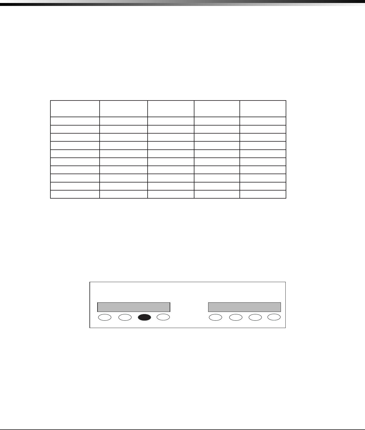
To change a programming option that requires a NO or YES response, press the select key for the response
not selected. See Figure 14.
For example, if the current option is selected as YES and you want to change it to NO, press the third select
key. The display changes to NO. Press the COMMAND key to display the next option.
Figure 14: Changing the Current Programming Option
THEN
Press the third top row
Select key.
The keypad displays the new
selection. Press CMD to advance.
YESBELL TST NOBELL TST

Digital Monitoring Products XTLplus Installation and Programming Guide
12
PROGRAMMING INTRODUCTION
19.8 Programming Menu
Accessing the Programmer
To access the programmer function of the XTLplus:
Use a standard LCD keypad, connect to the PROG header and set the keypad to Address 1.
Press the RESET button for two seconds.
Enter the code 6653 (PROG).
The keypad displays: PROGRAMMER.
Remove the hardwired keypad when programming is completed.
You are now ready to start programming the XTLplus panel. Pressing the COMMAND key scrolls you through
the programming menu items listed below.
Menu Item Section in This Manual Menu Item Section in This Manual
Initialization 20 BellOptions 29
FastProgram 21 OutputOptions 30
Communication 22 OutputSetup 31
NetworkOptions 23 Area Information 32
MessagingSetup 24 Zone Information 33
Device Setup 25 Stop 34
RemoteOptions 26 Set Lockout Code 35
System Reports 27 Appendix 36
SystemOptions 28
To select a section for programming, press any select key when the name of that section displays on the
keypad. The detailed instructions for each programming step are found in sections 20 to 35 of this manual.
19.9 Programmer Lockout Codes
Although the XTLplus panel allows access to Programming without a lockout code, it is available to program
one to restrict programming access to authorized individuals only. You can do this by using SET LOCKOUT
CODE at the end of the programming menu.
Installing a lockout code
1. After entering the Programmer menu, the keypad displays PROGRAMMER. Press the COMMAND key until
SET LOCKOUT CODE is displayed (after STOP).
2. Press any select key. At the ENTER CODE: - display, enter a 1- to 5-digit programmer lockout code.
Press COMMAND.
3. The display shows ENTER AGAIN. Enter the same lockout code again and press COMMAND. The display
shows CODE CHANGED. The new code number must now be entered before the Programmer menu can
be accessed.
The lockout code should be written down and kept in a secure place with access limited to authorized
persons only.
Lost Lockout Code requires factory reset: If you lose or forget the lockout code, the panel must be sent
back to the factory to be reset. There is no eld option for gaining access to the panel without a valid
lockout code.
19.10 Reset Timeout
The XTLplus has a feature that requires you to enter the Programmer within 30 minutes of resetting the
panel. After 30 minutes, if you attempt to program by entering the 6653 (PROG) code, the keypad displays:
RESET PANEL. You must reset the panel and enter the program code within the next 30 minutes.
If you are already in the Programmer and do not press any keys on the programming keypad for 30 minutes,
the panel terminates programming. All data entered up to that point is saved in the panel’s memory.
To exit the panel’s Programmer you must use the Stop function. The STOP option is the second to the last
option in programming. The programming session is then terminated and the keypad returns to the
Status List.
XTLplus Installation and Programming Guide Digital Monitoring Products
13
INITIALIZATION
Initialization
20.1 Initialization
This function allows you to set the panel’s programmed memory back to the
factory defaults in preparation for system programming.
After you select YES to clear a section of memory, the panel asks if you are sure
you want to clear the memory. This is a safeguard against accidently erasing part
of your programming. No memory is cleared from the programming until you
answer YES to the SURE? YES NO option.
CODES? NO YES
SCHEDS? NO YES
For each section of the panel program you
can initialize, a NO or YES option is provided.
Selecting YES advances you to
a confirmation prompt.
If you select YES, the panel initializes that section of
the program and advances you to the next prompt.
If you select NO, the panel advances you to the next
section prompt but does not initialize that section of
the program.
SURE? YES NO
Selecting NO advances
you to the next prompt.
20.2 Clear All Codes
NO - leaves existing user codes intact.
YES - clears the user code memory and assigns the user code number 99 to user 99
on the XTLplus.
20.3 Clear All Schedules
NO - Leaves existing schedules intact.
YES - Clears all schedules from the XTLplus programming.
20.4 Clear Events
NO - leaves existing event memory intact.
YES - clears all event memory currently held in the panel’s Display Events buffer.
20.5 Clear Zone Programming
NO - leaves existing zone information intact.
YES - sets all zones in the system to * UNUSED *.
20.6 Clear Communication
NO - Leaves existing communication and messaging programming intact.
YES - Resets communication and messaging programming to factory defaults.
20.7 Clear Wi-Fi
NO - Leaves existing Wi-Fi programming intact.
YES - Resets Wi-Fi programming to factory defaults.
20.8 Set to Factory Defaults
NO - leaves the remainder of the existing panel programming intact.
YES - sets the panel’s programming back to factory default selections and clears all
Z-Wave device programming and Favorites from the panel. Selecting YES does not
clear the panel’s event memory, zones, user code information, or schedules.
INITIALIZATION
CODES? NO YES
SURE? YES NO
SCHEDS? NO YES
SURE? YES NO
EVENTS? NO YES
SURE? YES NO
ZONES? NO YES
SURE? YES NO
COMM? NO YES
SURE? YES NO
CLEARWIFINOYES
SURE?YESNO
DEFAULTS?NO YES
SURE? YES NO

Digital Monitoring Products XTLplus Installation and Programming Guide
14
FAST PROGRAMMING
Fast Programming
21.1 Fast Program
The Fast Program section allows you to quickly congure the essential settings
for the XTLplus panel. When the panel programming defaults are acceptable
for installation and only basic programming options are needed, FAST PROGRAM
allows the installer to quickly enter information without navigating all of the
programming menus. After choosing FAST PROGRAM, continue through the basic list
of options.
21.2 Account Number
Enter the account num ber sent to the receiver. The range of account
numbers are 1 to 65535. For account numbers of four digits or less, you
do not have to enter leading zeros. The panel automatically right justies
the account number. See Communication.
21.3 First IP Address
Enter the rst (primary) IP address and press COMMAND. The panel displays WPS?
NO YES. Press the fourth select key to choose YES. Press the WPS button on the
router. WIFI SETUP SEARCHING displays until connected to the IP address. Advance
to APP Key. See Communication.
21.4 App Key
Enter the 8-digit App Key obtained in your Dealer Settings tab at
dealeradmin.securecomwireless.com. See Remote Options.
21.5 System
This congures the panel as either a six Area system, an All/Perimeter system
(Perimeter/Interior), or a Home/Away system (Perimeter, Interior, and Bedrooms).
See System Options.
21.6 Hours from GMT
Enter the number (0-23) that indicates the Greenwich Time zone (GMT) where the
panel is located. See System Options.
21.7 Weather Zip Code
Enter the zip code of the panel at this option. See System Options.
21.8 Enter Siren Serial Number
Enter the eight-digit serial number for the wireless siren. The siren is automatically
set to Output 61. See Output Setup.
21.9 Zone Number
Enter the zone number to program. See Zone Information.
21.10 Zone Name
Press any select key to display the default zone name. To change the default zone
name, press any select key to clear name. Enter up to 16 characters for the new
zone name.
21.11 Zone Type
To change the default zone type press any select key. See Zone Information.
21.12 Area Assignment
To change the default area, press any select key.
21.13 Serial Number Entry
Enter the eight digit serial number, including leading zeros, found on the
wireless device.
21.14 Stop
When all zones are programmed, press the Back Arrow key to display FAST
PROGRAM. Press COMMAND to display STOP and press any select key to exit the
Fast Program function and save the programming. See Stop.
Note: All programming options are still available by reentering the
programming menu.
FASTPROGRAM
ACCOUNTNO:
FIRST IP ADDR
0.0.0.0
SEARCHING
APPKEY:
SYSTEM:ALL/PERIM
AREA A/P H/A
HRSFROMGMT: 6
ENTER WEATHER
ZIPCODE: 0
ENTER SIREN
SERIAL#:-
ZONENO:-
*DEFAULTNAME*
ZONETYPE:-
AREA:-
SERIAL#:-
STOP
FIRST IP ADDR
WPS? NO YES

XTLplus Installation and Programming Guide Digital Monitoring Products
15
COMMUNICATION
Communication
22.1 Communication
The Communication section allows you to congure the communication settings
for the XTLplus panel. After choosing the Communication Type, continue through
the list of options.
22.2 Account Number
Enter the account num ber sent to the receiver.
The range of account numbers are 1 to 65535. For account numbers of four digits
or less, you do not have to enter leading zeros. The panel automatically right
justies the account number.
22.3 Transmission Delay
Enter the number of seconds (15 to 45 seconds) the panel waits before sending
burglary alarm reports to the receiver. The wireless siren and relay outputs are not
delayed during this period. Enter 0 (zero) to disable this function. The default is 30.
22.4 Communication Type
This species the communication method the panel uses to contact the receiver.
Press any select key to display the following communication options:
WIFI - Network communication to DMP Model SCS-1R or SCS-VR Receivers.
CEL - This option allows communication over the cellular network using the 265C
Cellular Communicator to DMP Model SCS-1R or SCS-VR Receivers.
NONE - For local systems. Selecting this ends communication programming.
Note: If automatic cellular activation is unsuccessful, cellular communication
must be activated using the Activate Cell option provided in Diagnostics Function
located in the Appendix.
22.5 Backup Cellular
Backup Cellular option is available if COMM TYPE is set for WIFI. The Backup
Cellular tries to send the message after the main communication fails for 60
seconds on WIFI. If the backup dialer fails then the message is discarded.
22.6 Test Time
Press COMMAND to enter the Test Time. Enter the time of day the panel sends the
test report to the SCS-1R Receiver. Use entries between 12:00 to 11:59 and then
choose AM or PM.
22.7 Test Days
Enter how often the panel test report is sent to the receiver. Enter from 1 to 60
days. Enter zero to disable the test report.
Default is 1 (one) day. This option only
displays if a test time is entered.
22.8 Check In Minutes
Check-in reports are a method of supervising the panel for communication with the
receiver. Enter the number of minutes between check-in reports. Select from 0 or
3-240 minutes. Enter 0 (zero) to disable the check-in option. Default is 200.
Note: If Cell Check-in option is used, additional cell charges may apply.
22.9 Fail Time
Fail Time allows the SCS-1R or SCS-VR receiver to miss a dened number of
check-ins before logging that the panel is missing. For example, if CHECKIN is 20
and FAIL TIME is 30, the SCS-1R receiver only indicates a Panel Not Responding
after 30 minutes. The FAIL TIME must be equal to or greater than the CHECKIN
minutes: If the CHECKIN is 20 minutes, the FAIL TIME must be 20 or more. The
maximum FAIL TIME is 240 minutes. Select from 0 or 3-240 minutes. The default
FAIL TIME is 240 minutes.
Closing Wait operation: Closing Wait operation is activated if Fail Time is set
to 3 minutes and O/C Reports in System Reports is YES and O/C User reports in
Communication Programming is set to YES.
Closing Wait provides a delay time before a monitored system arms until the
panel receives an acknowledgment of the closing report from the central station
receiver. During the delay, the keypad displays ONE MOMENT . . .
Once the closing is acknowledged from the SCS-1R receiver, the keypad buzzes
for one second and then displays an armed status message. If the primary
communication fails, the message LOCAL ALARM ONLY appears.
COMMUNICATION
ACCOUNTNO:
XMITDELAY: 30
COMMTYPE: CELL
WIFICELNONE
BACKUPCELL
NO YES
TEST TIME
00:00AM
TESTDAYS: 1
CHECKIN: 200
FAILTIME: 240

Digital Monitoring Products XTLplus Installation and Programming Guide
16
COMMUNICATION
22.10 Send Communication Trouble
Enable communication fail notication by selecting YES at COMM TRBL. Select NO
to disable. Default is YES.
When COMM TRBL is YES and the panel detects a failure of communication, the
panel sends an S72 (Comm Trouble) message through a backup communication
method with notication of the failure. If both primary and secondary methods
of communication fail, then two S72 messages will be sent via the third
communication method, if programmed. The keypad sounds a continuous tone,
which may be silenced by pressing any key, and displays “COMM -TRBL”.
When communication is restored, the panel sends an S73 (Comm Restored)
message through the primary communication. The “COMM -TRBL” message is
removed from the keypad display and the keypad sounder is turned off, if no other
trouble messages are pending.
Note: If the primary or secondary communication type is CELL, S72 and S73
messages include the cell signal strength as a -dBm value.
22.11 First Cell APN
Enter the rst APN (Access Point Name). This allows an access point for cellular
communication and is used to connect to a DNS network. The APN may contain two
lines of 16 characters to equal 32 characters. Default is set to SECURECOM400.
22.12 Second Cell APN
Enter the second APN (Access Point Name). This works as a backup in case the rst
APN fails. The APN may contain two lines of 16 characters to equal 32 character
Default is set to SECURECOM400.
22.13 Receiver 1 Programming
Allows you to set the options for the rst receiver the panel attempts to contact
when sending reports. The XTLplus supports communication to two receivers.
22.14 Alarm Reports
YES enables Abort, Alarm, Alarm Restoral, Alarm Bell Silenced, Ambush, Exit Error,
and System Recently Armed reports to be sent to this receiver. Default is YES.
22.15 Supervisory/Trouble Reports
YES enables Supervisory, Trouble, Trouble Restoral, Force Armed, Late to Close,
and Fault reports to be sent to this receiver. Default is YES.
22.16 Opening/Closing and User Reports
YES enables Opening/Closing, Code Changes, and Bypass reports by user to be sent
to this receiver. Default is NO.
22.17 Test Report
Enter YES to enable the Recall Test report to be sent to this receiver.
22.18 First IP Address
Enter the rst (primary) IP address where the panel sends network or cellular
information. Enter all 12 digits and leave out the periods. For example, enter IP
address 192.168.0.250 as 192168000250. The periods display automatically.
The message is sent using rst Cell APN and the rst IP Address. If no
acknowledgment is received, rst Cell APN and the second IP address are used,
followed, if needed, by second Cell APN and rst and second IP addresses,
respectively.
22.19 First IP Port
Enter the rst IP port number to be used in conjunction with the rst IP Address.
The IP port identies the port used to communicate messages to and from the
panel. The default IP Port setting is 2001.
22.20 Second IP Address
Enter the second (secondary) IP address where the panel sends network or cellular
information. Enter all 12 digits and leave out the periods. For example, enter IP
address 192.168.0.250 as 192168000250. The periods display automatically.
22.21 Second IP Port
Enter the second IP port number to be used in conjunction with the second IP
address. The IP port identies the port used to communicate messages to and from
the panel. The default IP Port setting is 2001.
COMMTRBLNO YES
SECURECOM400
-
FIRSTCELLAPN
SECURECOM400
-
SECONDCELLAPN
RECEIVER1PROG
ALARM NO YES
SPV/TRBL NO YES
O/CUSER NO YES
TESTRPT NO YES
FIRST IP ADDR
000.000.000.000
FIRSTIPPORT
2001
SECONDIPADDR
000.000.000.000
SECONDIPPORT
2001

XTLplus Installation and Programming Guide Digital Monitoring Products
17
COMMUNICATION
22.22 Receiver 2 Programming
Allows you to set the options for the second receiver the panel attempts to contact
when sending reports. The XTLplus supports communication to two receivers. If
you select YES for any of the Receiver 2 options, you must have at least one IP
address programmed in Receiver 2 programming. Receiver 2 defaults are set to NO.
22.23 Alarm Reports
YES enables Abort, Alarm, Alarm Restoral, Alarm Bell Silenced, Ambush, Exit Error,
and System Recently Armed reports to be sent to this receiver. Default is NO.
22.24 Supervisory/Trouble Reports
YES enables Supervisory, Trouble, Trouble Restoral, Force Armed, Late to Close,
and Fault reports to be sent to this receiver. Default is NO.
22.25 Opening/Closing and User Reports
YES enables Opening/Closing, Code Changes, and Bypass reports by user to be sent
to this receiver. Default is NO.
22.26 Test Report
YES enables the Recall Test report to be sent to this receiver. Default is NO.
22.27 First IP Address
Enter the rst (primary) IP address where the panel sends network or cellular
information. Enter all 12 digits and leave out the periods. For example, enter IP
address 192.168.0.250 as 192168000250. The periods display automatically.
The message is sent using rst Cell APN and the rst IP Address. If no
acknowledgment is received, rst Cell APN and the second IP address are used,
followed, if needed, by second Cell APN and rst and second IP addresses,
respectively.
22.28 First IP Port
Enter the rst IP port number to be used in conjunction with the First IP Address.
The IP port identies the port used to communicate messages to and from the
panel. The default IP Port setting is 2001.
22.29 Second IP Address
Enter the second (secondary) IP address where the panel sends network or cellular
information. Enter all 12 digits and leave out the periods. For example, enter IP
address 192.168.0.250 as 192168000250. The periods display automatically.
22.30 Second IP Port
Enter the second IP port number to be used in conjunction with the second IP
Address. The IP port identies the port used to communicate messages to and from
the panel. The default IP Port setting is 2001.
Network Options
Network Options are provided to dene the network conguration for the panel. This information will be
used during communication of messages via network.
Note: Wi-Fi must be selected as Communication Type in the Communication section for Wi-Fi Setup
to display.
Note: IP addresses and port numbers may need to be assigned by the network administrator. When
entering an IP, Gateway, or Subnet Mask address be sure to enter all 12 digits and leave out the periods.
For example, IP address 192.168.000.250 is entered as 192168000250.
23.1 Network Options
This option is for conguring the desired network settings. Press any select key to
select.
23.2 Wi-Fi Setup
This option is for connecting to the desired Wi-Fi network and will display only
when Comm Type is set to Wi-Fi. Press any select key to select.
WPS LIST MANUAL displays. Press the rst select key to choose WPS to
automatically connect to a WPS enabled router. Press the second select key to
choose LIST and see the name and signal strength of any Wi-Fi routers in range.
Press the third or fourth select key to choose MANUAL and enter the name of the
Wi-Fi router you wish to connect to. Pressing COMMAND displays TEST. To select
TEST press the rst select key to verify connection of your system to the Wi-Fi
network.
RECEIVER2PROG
ALARM NO YES
SPV/TRBL NO YES
O/CUSER NO YES
TEST RPT NO YES
FIRST IP ADDR
000.000.000.000
FIRSTIPPORT
2001
SECONDIPPORT
2001
NETWORK OPTIONS
NETWORKOPTIONS
WPSLISTMANUAL
TEST
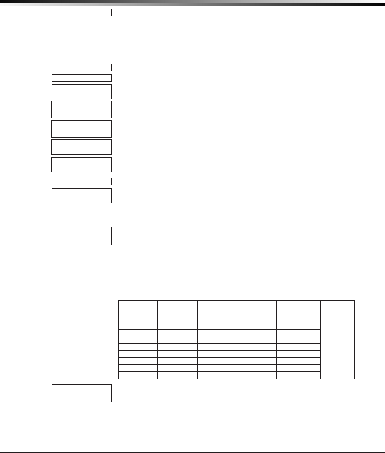
Digital Monitoring Products XTLplus Installation and Programming Guide
18
NETWORK OPTIONS
23.2.1 WPS
When WPS is selected, SEARCHING displays. Press the WPS button on the Wi-Fi
network router to which you are attempting to connect. SEARCHING displays for up
to two minutes or until connected to the WPS enabled router. Refer to the router’s
instruction manual for sending a security key to the XTLplus Series panel.
If the panel fails to connect to the WPS enabled router, WPS FAILED RETRY? NO
YES displays. Press the fourth select key to RETRY or press the third select key to
display WPS LIST MANUAL.
23.2.2 List
When LIST is selected, SEARCHING displays until any Wi-Fi networks are found
in range. Once available Wi-Fi networks are found the keypad displays the name
of the SSID (Wi-Fi Network name) and signal strength of each network. Press
COMMAND to scroll through the list of available Wi-Fi networks. When the desired
network is displayed, press any select key to connect.
Note: If the panel is unable to detect the security type, W/L SECURITY with the
default security type WPA-PSK displays. If a different security type is required,
press COMMAND and WEP WPA NONE displays. Press the select key of the desired
security type to choose.
When connecting to the Wi-Fi network the panel also detects the security type in
use and W/L KEY: *************** displays.
Enter the W/L KEY and the panel performs a connection test and CONNECTING
displays. When successful, CONNECTED displays on the keypad. If the panel does
not connect to the Wi-Fi network, NOT CONNECTED displays. Press COMMAND to
return to the WIFI SETUP main screen.
23.2.3 Manual
This option allows you to enter the desired network name using the keypad. When
MANUAL is selected, the current settings display. Press COMMAND to continue with
no change. SecureCom is the default.
Use the number keys on the keypad to enter a new or different SSID (Wi-Fi
Network name), there is no need to press the select keys or areas. Once the SSID is
entered, press COMMAND and SEARCHING displays.
When an SSID is entered for the rst time or changed, the panel searches for the
SSID entered to ensure communication. The keypad displays SSID FOUND or SSID
NOT FOUND. When the SSID is found, the security type is also detected.
Note: Depending on the security type, the SSID might take several seconds to
process.
Enter up to 32 characters for the SSID from the network router to identify the
network LAN. The SSID is blank by default. Use the chart below to enter lowercase
or special characters. Each successive press of the select key gives additional
options. For example, to enter Me5%, you would press key # 5, select key 1 (M);
press key # 2, select key 2 twice (e); press key # 5 (5); press key # 7, select key 4
twice (%).
Key Number Select key 1 Select key 2 Select key 3 Select key 4
Note:
When \ is
entered,
the keypad
displays ¥.
When ~ is
entered, ->
displays.
1 A, a, B, b C, c (, [, {
2D, d E, e F, f ), ], }
3G,g H,h I, i !, ^, ~
4J, j K, k L,l ?, ", |
5 M, m N, n O,o /, \, `
6P, p Q, q R, r &, $
7S, s T, t U,u @, %
8V, v W, w X, x , =
9Y, y Z, z space,: _, ;
0 -, + ., ' *, < #, >
While searching, SEARCHING displays on the keypad. If the panel can not connect
to the desired network SSID NOT FOUND displays. Press COMMAND to return to the
main menu and WPS LIST MANUAL displays. Press COMMAND again to display TEST.
SEARCHING .
WPSLISTMANUAL
SEARCHING
SIGNAL
▐▐▐▐▐▐▐
HOMENET123
W/LSECURITY:
WPA-PSK
W/LSECURITY:
WEPWPANONE
W/LKEY:
*****************
W/LKEY:
-
WIFISETUP
ENTER SSID
WPSLISTMANUAL
SSID:
SSIDFOUND
SSID:
SSIDNOTFOUND
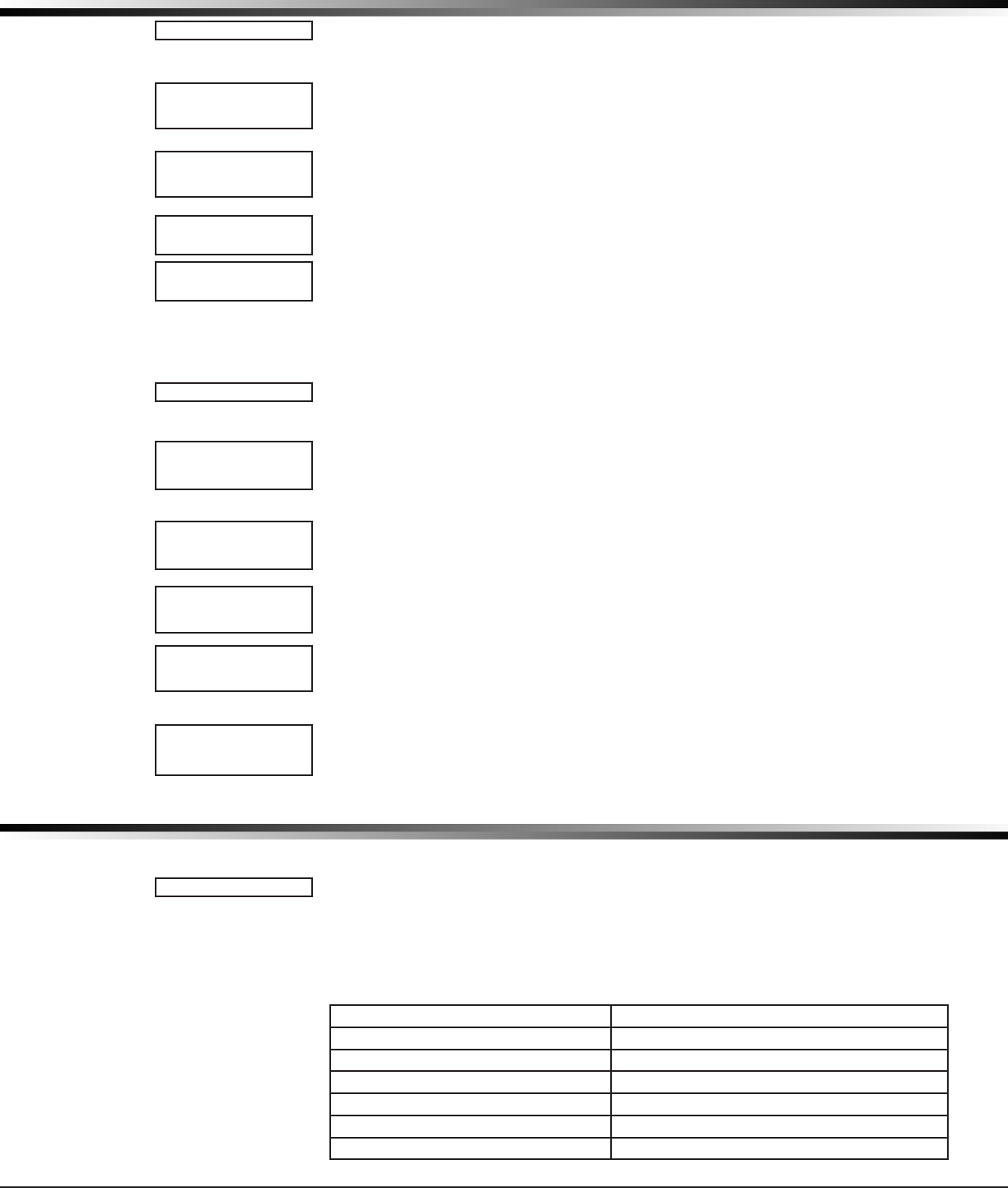
XTLplus Installation and Programming Guide Digital Monitoring Products
19
NETWORK OPTIONS
23.2.4 Test
Press the rst select key to select TEST and the panel will attempt to verify
connection of your system to the desired Wi-Fi network.
23.3 Wireless Security Type
When successful, W/L SECURITY displays. Select the security type based on the
network router programming. The default network security type is WPA-PSK. Press
any select key to display the other security options. The available options are WEP,
WPA, and NONE.
Press the rst select key to choose WEP, press the second select key for WPA, press
the third select key for NONE.
23.4 Wireless Network Key
This option displays only if Comm Type is set to Wi-Fi and Security option is not
set to NONE. Enter the key provided from the network router’s programming. WEP
requires a network password of 10 characters (WEP64) or 26 characters (WEP128),
using a combination of the number 0-9 and the letters A-F. WPA/WPA-PSK uses a
custom key that allows 8 to 32 characters (See the chart above to enter lowercase
or special characters). Press COMMAND to save the key.
Note: Depending on the security type, the key might take several seconds
to process.
23.5 DHCP
If the panel uses a dynamic IP address Select YES. When set to YES the panel
operates in DHCP and will not use the Local IP Address number.
23.6 Local IP Address
Enter the local IP address for the panel. The Local IP Address must be unique
and cannot be duplicated on the network. The default local IP address is
192.168.000.250.
23.7 Gateway Address
Enter the local gateway address. The Gateway IP Address is needed to exit the
local network. The default gateway address is 192.168.000.001.
23.8 Subnet Mask
Enter the local subnet mask assigned to the panel. The default subnet mask
address is 255.255.255.000.
23.9 DNS Server
Enter the IP address of the DNS (Domain Name System) used by the panel to
resolve domain names into IP addresses. The default address is 192.168.000.001.
Note: The DHCP programming in the panel must be set to NO.
23.10 Programming Port
Enter the programming port number. The programming port identies the port
used to communicate messages to and from the panel. The default Programming
Port setting is 2001.
Messaging Setup
24.1 Messaging Setup
This section allows you to enter the information needed to send and receive
messages directly to and from the panel via MyAccess™ text messaging using
cellular communication. All of the name and password options below allow up to
32 lowercase characters to be entered. The Destination addresses allow up to 48
characters to be entered. System Name is displayed with initial caps.
The transmitted messages are:
Zone Alarms by Zone Name Early to Close
Zone Troubles by Zone Name AC Power Trouble and Restoral
Zone Bypass by User System Low Battery
Arming (Closings) by User Ambush
Disarming (Openings) by User Abort, Cancel and Alarm Veried by User
Late to Close Check-in by User
Late to Open
TEST
W/LSECURITY:
WPA-PSK
W/LSECURITY:
WEPWPANONE
W/LKEY:
*****************
W/LKEY:
-
DHCP NOYES
LOCALIPADDR
192.168.000.250
GATEWAY ADDR
192.168.000.001
SUBNETMASK
255.255.255.000
DNS SERVER
192.168.000.001
PROGRAMMINGPORT
2001
MESSAGING SETUP
MESSAGINGSETUP

Digital Monitoring Products XTLplus Installation and Programming Guide
20
MESSAGING SETUP
24.2 Enable Messaging
Select YES to allow the panel to send messages to three programmed destinations.
Default is NO.
24.3 System Name
Enter a unique name for the panel. The panel name is used as the sender of the
message. The text entered is displayed with initial caps. If this eld is left blank,
the panel account number is sent.
24.4 Destination 1
Enter the rst cell phone number where text messages will be sent. The message can
be sent to any device (computer or cell phone) as long as a valid cell phone number
is entered.
24.5 Destination 1 User Number
E
nter a valid, previously-programmed user number. This option is used when sending
commands such as arming or disarming back to the pan el using MyAccess™ SMS Text from
the same cell phone. The user number must have the authority to perform the commands
as if it occurred at the keypad. Entering 0 (zero) disables this option. Default is 0.
24.6 Destination 2
Enter the second destination cell phone number.
24.7 Destination 2 User Number
Enter a valid User Number for arming/disarming authorization.
24.8 Destination 3
Enter the third destination cell phone number.
24.9 Destination 3 User Number
Enter a valid User Number for arming/disarming authorization.
24.10 O/C SMS
Select YES to allow the panel to send Opening and Closing messages to a cell phone
via SMS protocol. Default is NO. This option appears only if any destination above is
a cell phone number.
24.11 Monthly Limit
This option displays if any programmed destination is a cell phone number using
CELL communication. This number limits the monthly incoming and outgoing SMS
messages allowed to be sent or received by the panel.
A panel event that causes messages to be sent to destination cell phone numbers
is counted towards the panel’s monthly limit. For example, if an alarm message
is sent to a cell phone number, a total of 2 messages are counted towards the
monthly limit for the panel. SMS messages sent from a cell phone to the panel,
including status requests and MyAccess™ SMS Text messaging commands, also
count toward the monthly limit. The limit is reset at midnight on the 14th of every
month. Range is from 0 to 999. When 0 is entered, there is no limit on the number
of messages able to be sent or received by the panel. Default is 0.
Note: The SecureCom Wireless text plan selected for the panel should match or
exceed the programmed Monthly Limit.
Device Setup
25.1 Device Setup
This section allows you to dene the XTLplus panel wireless keypad conguration.
You can install and address up to four wireless keypads.
25.2 Device Number
Enter the device number of the wireless keypad you are programming. The valid
range is 2-5.
Note: Address one is reserved for the XTLplus programming keypad attached
during programming. After you program each option for the rst keypad, repeat
these programming steps for each additional keypad.
ENABLEMESSAGING
NO YES
SYSTEM NAME
-
DESTINATION1
-
DESTINATION1
USERNUMBER:
0
DESTINATION2
-
DESTINATION2
USERNUMBER: 0
DESTINATION3
DESTINATION3
USERNUMBER: 0
O/CSMS NO YES
MONTHLYLIMIT:0
DEVICESETUP
DEVICENO:-
DEVICE SETUP
XTLplus Installation and Programming Guide Digital Monitoring Products
21
DEVICE SETUP
25.3 Device Name
This section allows you to dene a 16 character alphanumeric name for the device
number. If no name is entered, *UNUSED* is displayed.
To remove a keypad from the system, delete the device name by pressing any
select key, then press the COMMAND key. The device name is now displayed as *
UNUSED *.
25.4 Wireless
Select YES to use a wireless keypad. Default is YES.
25.5 Serial Number
Enter the eight-digit serial number found on the wireless keypad.
25.6 Supervision Time
Press any top row key to select the supervision time required for the device. Press
COMMAND to accept the default time. Default is 240 minutes.
Press the select key under the required number of minutes. The device must check
in at least once during this time or a missing condition is indicated for that device.
Zero (0) indicates an unsupervised wireless keypad.
Note: When the panel is reset, panel is powered down and powered up, or
programming is complete, the supervision timer restarts for all wireless keypads.
Remote Options
26.1 Remote Options
This section allows you to enter the information needed for Remote Command/
Remote Programming operation via Wi-Fi communication. A description of the
Remote Options follows:
26.2 Remote Key
This option allows you to enter a code of up to eight digits for use in verifying
the authority of an alarm or service receiver to perform a remote command/
programming session. The receiver must give the correct key to the panel before
being allowed access. All panels are shipped from the factory with the Remote Key
preset as blank.
To enter a new Remote Key, press any select key and enter any combination of up
to 8 digits. The numbers you enter appear as asterisks.
Press COMMAND.
26.3 Manufacturer Authorization
Enter YES to allow DMP service technicians to access the panel when required
during system service or troubleshooting. This authorization automatically expires
within one hour.
DMP remote service is provided on a read only basis: DMP technicians can look at
the system programming and make suggestions only.
26.4 Alarm Receiver Authorization
Enter YES to enable remote commands and programming to be accepted from the
alarm SCS-1R Receiver. The Remote Key option can also be required.
When YES is selected, the panel requests the alarm receiver key during its rst
alarm communication with the rst SCS-1R receiver. The panel retains this alarm
receiver key in memory and allows remote commands to be accepted from the
alarm receiver. If an alarm occurs during a remote connect, the alarm report is
immediately sent to this receiver only.
When NO is selected, remote commands and programming are not accepted from
the alarm SCS-1R receiver.
26.5 Service Receiver Authorization
YES enables remote commands and programming to be accepted from a secondary
service receiver other than the alarm SCS-1R Receiver. The Remote Key option can
also be required.
With YES selected, the panel requests the service receiver key the rst time it is
contacted by the service receiver. The panel retains this service receiver key in
memory and accepts remote commands from the service receiver.
*UNUSED*
WIRELESS?NOYES
SERIAL#:XXXXXXXX
SUPRVSNTIME:240
SELECTMINUTES:
0 60 240
REMOTE OPTIONS
REMOTEOPTIONS
RMTKEY:
MFGAUTH NO YES
ALRRCVR NO YES
SVCRCVR NO YES

Digital Monitoring Products XTLplus Installation and Programming Guide
22
REMOTE OPTIONS
If an alarm occurs during a remote connect, the panel disconnects from the
service receiver and connects to the alarm receiver. Alarm reports are only sent
to the alarm receiver. It is important that the alarm receiver key and the service
receiver key programmed at the central station are NOT the same so the panel can
determine the difference between receivers.
When NO is selected, remote commands and programming are not accepted from a
secondary service receiver.
26.6 Remote Disarm
Enter YES to enable the panel to be disarmed remotely. Selecting NO disables
remote disarming. Default is YES.
26.7 App Key
Enter the 8-digit App Key obtained in your Dealer Settings tab at
dealeradmin.securecomwireless.com.
This option is a security feature of the Virtual Keypad iPhone/Android App used
only when your Dealer Settings at dealeradmin.securecomwireless.com have
“EASYconnect” set as the Communication Type.
This communication option is used to eliminate the need for a static IP address
programmed in Network Options.
To enter the App Key, press any select key and enter any combination
of 8 digits.
Press COMMAND. The default for this option is blank.
System Reports
27.1 System Reports
This function allows you to select the reports the XTLplus sends to the receiver.
27.2 Opening/Closing Reports
NO - No Opening/Closing Reports are sent.
YES - Sends Opening/Closing Reports for each programmed area.
27.3 Abort Reports
YES allows the panel to send an Alarm Abort Report to the receiver any time an
area is disarmed during Transmit Delay before an alarm report is sent and the
Bell Cutoff Time has not expired. See the Bell Cutoff section. The area must be
disarmed and no zones that were in alarm can still be armed.
YES also allows a Bell Silenced Report to be sent if the alarm bell is silenced with a
valid user code during an alarm. Default is NO.
Note: Alarm Cancel or Verify Reports are sent if the alarm is canceled or veried
after being sent to the alarm receiver, if the Bell Cutoff timer has not expired. The
Abort Reports option does not affect Cancel or Verify reports.
The panel will not send Abort reports for Fire zones, or Supervisory-type zones.
27.4 Zone Restoral Reports
This option allows you to specify whether the panel sends zone restoral reports and
when they will be sent.
NO - Restoral reports are not sent by the panel.
YES - The panel always sends zone restoral reports at the time the zone restores
from an alarm or trouble condition.
DISARM - The panel sends zone restoral reports when a zone that has restored
from an alarm or trouble is disarmed. Twenty-four hour zones send
restorals immediately.
27.5 Bypass Reports
YES allows the panel to send all zone bypass, reset, and force arm reports to the
receiver. The bypass report includes the zone number, zone name, and the user
number of the individual bypassing the zone.
27.6 Code Change Reports
YES allows the panel to send all code additions, changes, and deletions to the
receiver. The code change report includes the user number added or deleted and
the user number of the individual making the change.
DISARM NO YES
APPKEY:
SYSTEM REPORTS
SYSTEMREPORTS
O/CRPTSNO YES
ABORT NO YES
RESTORALYES
NO YESDISARM
BYPASS NO YES
CODECHG NO YES

XTLplus Installation and Programming Guide Digital Monitoring Products
23
SYSTEM REPORTS
27.7 Ambush
YES allows an ambush report to be sent any time user code number one is entered
at a keypad. Selecting NO disables the ambush report and allows user code number
one to operate the same as all other codes.
27.8 Late To Open
Enter 1-240 as the number of minutes to elapse that the system may remain armed
after the opening time of a schedule without sending a Late To Open message. If
the system continues to be armed after the Late to Open minutes expire, a Late To
Open message is sent to the central station. Default is 0, which disables the Late
To Open option.
27.9 Early To Close
Enter 1-240 as the number of minutes that the system can be armed prior to the
scheduled closing time. If the system is armed prior to the Early to Close minutes,
an Early To Close message is sent to the central station. Default is 0, which
disables the Early to Close option.
System Options
28.1 System Options
This section allows you to select system wide parameters used in the operation of
the XTLplus panel. A description of each System Option follows:
28.2 System
This congures the panel as either a six Area system, an All/Perimeter system
(Perimeter/Interior), or a Home/Away system (Perimeter, Interior, and Bedrooms).
Zones must be assigned to Bedrooms for the area to be active.
Wireless zones in an Area or All/Perimeter system resound the trouble buzzer every
four hours when zone trouble or low battery is displayed.
28.3 Closing Code
When YES is selected, a code number is required for system arming. If NO is
selected, a code number is not required for system arming. Default is NO.
28.4 Closing Check
Select YES to enable the panel to verify that all areas have been armed after a
schedule expires. If the Closing Check nds any areas disarmed past the scheduled
time, all keypads emit a steady beep and display CLOSING TIME!. The user must
extend the schedule or arm the system within 10 minutes or a Late to Close
message is sent to the central station. Default is NO.
28.5 Entry Delay 1
Enter the entry delay time for all exit type zones programmed to use Entry Delay
1. When an armed Exit type zone is faulted, the keypad prewarn tone begins
sounding. ENTER CODE: - and the name of the zone causing the Entry Delay
displays on all keypads.
When the rst digit of a code is entered, the prewarn tone stops at the keypad.
If, within ve seconds, a valid user code is not entered or an invalid user code is
entered, the prewarn tone begins sounding again. Fifteen seconds must elapse
before entering a digit silences the prewarn tone again.
The area must be disarmed before the entry delay expires or an alarm is detected.
All Burglary type zones in all areas are delayed along with the Exit zone.
Entry delay times can be from 30 to 250 seconds. Repeat the above for Entry Delay
2 if it is being used. Default is 30 seconds for Entry Delay 1.
Note: Specic Exit Error operation is based on the Entry Delay used (1 or 2) with an
EX type zone. See Exit Delay.
28.6 Exit Delay
Enter the Exit Delay time for all Exit type zones. When the exit delay time starts,
all activity on exit and burglary zones is ig nored until the exit delay expires. The
keypad displays the Exit Delay time countdown and annunciates the Exit Delay
tone at 8 second intervals until the last 10 seconds when annunciation is at 3
second intervals. The exit de lay can be from 45 to 250 sec onds. Default is 60
seconds. During Exit Delay, if an exit zone trips, then restores, and trips again, the
AMBUSH NO YES
LATETOOPEN
MINUTES: 0
EARLYTOCLOSE
MINUTES: 0
SYSTEM OPTIONS
SYSTEMOPTIONS
SYSTEM:ALL/PERIM
AREA A/P H/A
CLSCODE NO YES
CLSCHK NO YES
ENTRYDLY1: 30
ENTRYDLY2: 60
EXITDELAY: 60

Digital Monitoring Products XTLplus Installation and Programming Guide
24
SYSTEM OPTIONS
Exit Delay timer restarts. This restart can occur only once.
Exit Error Operation: At arming, when an entry/exit zone (EX) is faulted at the end
of the exit delay then one of two sequences occur:
For Entry Delay 1 EX type zones:
• The bell sounds for the length of time set in Bell Cutoff programming
• The Entry Delay operation starts, requiring code entry to disarm
• If not disarmed, a zone alarm and an Exit Error are sent to the receiver
For Entry Delay 2 EX type zones:
• The zone is force armed and a zone force arm message is sent to the receiver
• An Exit Error is sent to the receiver
• The bell sounds for the length of time set in Bell Cutoff programming
28.7 Cross Zone Time
Enter the time allowed between zone faults. When a zone programmed for cross
zoning faults, the panel begins counting down the Cross-Zone Time entered here. If
the same zone or another cross-zoned zone faults within this time, an alarm report
is sent to the receiver.
If the Cross-Zone Time expires without the second zone fault, only a zone fault
report from the rst zone is sent to the receiver. The Cross-Zone Time can be from
4 to 250 seconds in one second increments. Enter 0 (zero) to disable the Cross-
Zone Time feature. Default is 0 (zero). See the Appendix.
28.8 Power Fail Delay
This option tracks the duration of an AC power failure. The delay time can be from
1 to 9 hours. When the AC power is off for the length of the programmed delay
time, an AC power failure report is sent to the receiver. For example, if the power
failure delay is set for two hours, then the AC power failure report will be sent
between 2-3 hours. Entering a 0 (zero) sends the AC power failure report within 15
seconds. Default is 1.
28.9 Swinger Bypass Trips
Enter the number of times (1-6) a zone can go into an alarm or trouble condition
within one hour be fore being auto matically bypassed. Bypassed zones are auto-
matically reset when the area they are assigned to is disarmed. All 24-hour zones
are reset when any area of the system is dis armed. A programming Stop operation
restores a bypassed zone. Entering 0 (zero) disables this function. Default is 2.
How it works
The panel hour timer starts at 59 minutes past the hour. If the hour timer expires
before the trip counter is exceeded, the trip counter returns to 0 (zero). If the trip
counter is exceeded before the hour expires, the zone is auto matically bypassed
by the panel. A Bypass Re port is sent to the receiver if Bypass Re ports is YES.
Note: Not investigated by Intertek.
28.10 Reset Swinger Bypass
When YES is selected, an auto matically bypassed zone is reset if it remains in
a normal condition for one complete hour after being bypassed. A report of the
automatic reset is sent to the receiver if Bypass Reports has been se lected as YES.
Default is NO.
Note: Not investigated by Intertek.
28.11 Zone Activity Hours
This option provides supervision of a person living alone for non-activity. Enter the
number of hours, 0 to 9, allowed to elapse without a disarmed zone being tripped
before a message is sent to the receiver. Default is 0 (zero).
When the system is disarmed, the timer begins to countdown the number of hours
programmed. Each time activity occurs, the timer restarts the countdown.
Before the countdown time expires, the keypad sounds a tone and PRESS ANY KEY
displays to allow the user to restart the activity timer. The duration of the tone is
the number of seconds programmed for Entry Delay 2.
Select the SUPV/TRBL receiver option in communication programming to send S93
ALARM: User Activity Not Detected, S94 Alert: Activity Check Enabled, and S95
Alert: Activity Check Disabled messages.
When an open/close schedule is programmed, the timer only counts down during
the scheduled open period. Also, when a schedule is programmed, if the timer is
counting down and the scheduled open time occurs, the timer resets and begins
the countdown again.
CRSZONETM: 0
PWRFAILHRS: 1
SWGRBYPSTRIPS: 2
RST SBYP NO YES
ZNACTYHRS: 0

XTLplus Installation and Programming Guide Digital Monitoring Products
25
SYSTEM OPTIONS
28.12 Arm Activity Days
This allows selection of the number of days a countdown timer is set for area
arming and disarming activity. The range for the countdown timer is 00 to 99.
When the timer counts down to zero because of no arming or disarming activity,
the panel sends a “No Arming/Disarming” message to the receiver at 10:00
AM. Each time an area is armed or disarmed, the timer is restarted. When the
countdown timer expires because of no arming or disarming activity, and a
message is sent, the timer does not restart until a panel reset occurs or an area is
armed or disarmed.
The SUPV/TRBL receiver option must be selected in communication programming
for the message to be sent.
28.13 Time Zone Changes
This option allows the panel to request automatic time changes from the DMP SCS-
1R Receiver. For the receiver to send time changes, it must be programmed to send
time changes and must be receiving time change updates from the host automation
computer at least every 24 hours. Default is YES.
When time zone is programmed YES, enter the number (0-23) that indicates the
Greenwich Time zone (GMT) where the panel is located. The default is 6. See table
for GMT values.
GMT City/Time Zone GMT City/Time Zone
0London,Monrovia,Lisbon,Dublin,Casablanca,Edinburgh 13 New Cadelonia
1 Cape Verde Island, Azores 14 Guam, Sydney
2Mid-Atlantic,FernandodeNoronha 15 Tokyo, Seoul
3BuenosAires,Georgetown,Brasilia,RiodeJaneiro 16 HongKong,Singapore
4AtlanticTime(Canada),Caracas,LaPaz,Santiago 17 Bangkok,Hanoi
5EasternTime(US,Canada)Bogota,Lima,Arequipa 18 Dhaka,Almaty
6CentralTime(US,Canada),MexicoCity,Saskatchewan 19 Islamabad,Karachi
7MountainTime(US,Canada),Edmonton 20 AbuDhabi,Kazan
8PacicTime(US,Canada),Tijuana 21 Moscow,Bagdad
9 Alaska 22 Eastern Europe
10 Hawaii 23 Rome, Paris, Berlin
11 Midway Island, Samoa
12 Fiji,MarshallIsland,Wellington,Auckland,Kwajalein,Kamchatka
28.14 Time Display
YES allows the keypad to display the time and day in the Status List. When NO is
selected, time and day of the week are not displayed.
28.15 House Code
A Wireless House Code between 1 and 50 is pre-programmed at the factory. To
change the house code, press any select key. Enter a House Code from 1 to 50 and
press the CMD button. The XTLplus automatically programs the house code into the
wireless transmitters when the unique transmitter serial number is programmed
into the panel. See Wireless programming in Zone Information. The house code
identies the panel, receiver, and transmitters to each other. When operating,
the receiver listens for transmissions that have the programmed house code and
transmitter serial number.
28.15.1 Detect Wireless Jamming
When enabled and the receiver detects jamming, a trouble or alarm message is
sent to the receiver and displays in the Status List. Select YES to enable jamming
messages to display in the Status List. Select NO to disable jamming messages.
Default is NO.
28.15.2 Wireless Audible Annunciation
Press any top row key to select the keypad buzzer annunciation method for
wireless low battery and missing messages.
Select ANY to enable annunciation anytime.
Select DAY to enable annunciation except during sleeping hours (9 PM to 9 AM).
Select MIN (minimum) to annunciate only Fire zones during daytime hours (9 AM to
9 PM). Default is DAY.
ARMACTYDAYS: 0
TIMECHG NO YES
HRSFROMGMT: 6
TIMEDSP NO YES
HOUSECODE: -
DET JAMNG NO YES
WLS AUDIBLE:DAY
ANY DAY MIN

Digital Monitoring Products XTLplus Installation and Programming Guide
26
SYSTEM OPTIONS
28.16 Enable Keypad Panic Keys
This option allows the two-button panic key operation selected at a keypad to send
the Panic, Emergency, or Fire message to the central station receiver. Select YES to
enable the two-button panic operation. To disable the two-button panic operation,
select NO. Default is YES.
28.17 Occupied Premises
Select YES to allow the panel to automatically disarm the interior area(s) when
arming all areas and a perimeter zone is not tripped during the exit delay.
This False Alarm Reduction feature keeps a user from arming the entire system
when they do not exit and remain in the premises. Select NO to not automatically
disarm interior area(s). Default is NO.
28.18 Use False Alarm Question
Select YES to display IS THIS A FALSE ALARM? NO YES at the keypad in place of
CANCEL VERIFY when a burglar alarm occurs. Select NO to display CANCEL VERIFY
for burglar alarms. This operates for ALL/PERIM and HOME/SLEEP/AWAY arming
systems. Default is YES.
28.19 Weather Zip Code
This option allows local U.S.A. weather updates to display in the Status List on the
keypad. Enter the zip code of the user at this option. When no number is entered
weather conditions are not displayed. Default is -.
Bell Options
29.1 Bell Options
This section allows you to program the panel bell output functions. If using the
Model 1135 or 1135DB Wireless Siren, the Trip with Panel Bell option should be
selected in the Output Information programming for the siren.
29.2 Bell Cutoff Time
Enter the maximum time from 1 to 15 minutes that a wireless output remains on. If
the output is manually silenced or the system is disarmed, the cutoff time is reset.
Default is 5.
29.3 Automatic Bell Test
When YES is selected, the 1135/1135DB wireless siren is turned on for two seconds
when all areas in the system are armed. The Bell Test only occurs when the areas
are armed from a keypad. Arming performed from an Arming zone or remotely
from Remote Link™ does not activate the Bell Test.
Closing Wait operation
When Bell Test is set to YES, the closing wait function also operates. Closing Wait
provides a delay time before a monitored system arms until the panel receives an
acknowledgment of the closing report from the central station receiver. During the
delay, the keypad displays ONE MOMENT . . . Once the closing is acknowledged,
the keypad buzzes for one second and then displays the ALL SYSTEM ON message. If
communication fails, the message LOCAL ALARM ONLY appears.
29.4 Bell Output
Enter the output number (51-54, 61-64) for an 1116 or 1117 wireless output
when needed to follow the on and off condition of the bell action. Enter 0
(zero) to disable.
Note: When BELL ACTION below is set to T for Temporal Code 3, this Bell Output
action will be Pulse for wireless outputs 51-54 and 61-64.
29.5 Bell Action
This denes the type of Bell Action from zone alarms that will occur. Trouble
conditions do not activate Bell Action. There are seven zone types you can
program individually for Bell Output. To provide a steady Bell Output, enter S.
For a pulsed output, enter P. For a Temporal Code 3 output, enter T and for no
bell action, enter N.
29.5.1 Fire
Denes Bell Action for Fire Type Zones. The default is set at T.
29.5.2 Burglary
Denes Bell Action for Burglary Type Zones. The default is set at S.
KPDPANCSNOYES
OCCUPIEDPREMISE
NO YES
USEFALSEALARM
QUESTION?NOYES
ENTER WEATHER
ZIPCODE: -
BELL OPTIONS
BELLOPTIONS
BELLCUTOFF: 5
BELLTEST NO YES
BELLOUTPUT: 0
BELLACTION...
FIRE TYPE: T
BURGLARYTYPE: S

XTLplus Installation and Programming Guide Digital Monitoring Products
27
BELL OPTIONS
29.5.3 Supervisory
Denes Bell Action for Supervisory Type Zones. The default is set at N.
29.5.4 Panic
Denes Bell Action for Panic Type Zones. The default is set at N.
29.5.5 Emergency
Denes Bell Action for Emergency Type Zones. The default is set at N.
29.5.6 Auxiliary 1
Denes Bell Action for Auxiliary 1 Type Zones. The default is set at N.
29.5.7 Auxiliary 2
Denes Bell Action for Auxiliary 2 Type Zones. The default is set at N.
Output Options
30.1 Output Options
This section allows you to program output options for the 1116 and 1117 wireless
outputs. Select from the following output numbers:
• 51 to 54
• 61 to 64
• F01 to F20 (To Activate Z-Wave Favorites)
30.2 Communication Failure Output
This output/Favorite turns on when the panel fails to communicate with the
receiver after three communication attempts. Enter 0 (zero) to disable this output.
Note: To turn off the Communication Failure Output, disarm the panel or turn the
output off using the User Menu Outputs On/Off function.
30.3 Fire Alarm Output
This output turns on any time a re type zone is placed in alarm. The output turns
off using the Sensor Reset option when no additional re type zones are in alarm.
Enter 0 (zero) to disable this output.
30.4 Fire Trouble Output
This output/Favorite turns on any time a re type zone is placed in trouble or
when a supervisory type zone is placed in alarm or trouble. The output turns
off when all re and supervisory type zones restore to normal. Enter 0 (zero)
to disable.
30.5 Ambush Output
This output/Favorite turns on any time an Ambush code is entered at a keypad.
The output turns off using the Sensor Reset option. Enter 0 (zero) to disable
this output.
30.6 Begin Exit Output
This output/Favorite turns on any time an exit delay time starts. The output turns
off when the system arms or when the arming has been stopped. Enter 0 (zero)
to disable.
30.7 End Exit Output
This output/Favorite turns on any time an exit delay time ends. The output turns
off when the system disarms. Enter 0 (zero) to disable.
30.8 Ready Output
This output/Favorite turns on whenever all disarmed zones are in a normal state.
The output turns off when any disarmed zone is in a bad state. Enter 0 (zero)
to disable.
30.9 Armed Output
This output/Favorite turns on any time an area of the system is armed. The
output turns off when the system completely disarms. Enter 0 (zero) to disable
this output.
Favorites:
For a Home/Away system:
When the system is armed AWAY, the programmed Favorite activates.
When the system is armed SLEEP, the programmed Favorite plus 1 is activated.
SUPRVSRYTYPE: N
PANIC TYPE: N
EMERGNCYTYPE: N
AUXLRY1 TYPE: N
AUXLRY2 TYPE: N
OUTPUT OPTIONS
OUTPUTOPTIONS
COMFAILOUT: 0
FIREALROUT: 0
FIRETRBOUT: 0
AMBUSH OUT: 0
BEGINEXIT:0
ENDEXIT:0
READY OUT: 0
ARMED OUT: 0

Digital Monitoring Products XTLplus Installation and Programming Guide
28
OUTPUT OPTIONS
For example, If the Armed Output is F05, F06 activates when Sleep is armed.
When the system is armed HOME, the programmed Favorite plus 2 is activated.
For example, If the Armed Output is F05, F07 activates when Home is armed.
For an All/Perimeter system:
When the system is armed ALL, the programmed Favorite activates.
When the system is armed PERIMETER, the programmed Favorite plus 1
is activated.
For example, If the Armed Output is F05, F06 activates when Perimeter is armed.
For an Area system:
When any area of the system is armed, the programmed Favorite activates.
30.10 Disarmed Output
This output/Favorite turns on when all areas of the panel are disarmed. The output
turns off when an area is armed.
30.11 Burglary Output
This output/Favorite turns on any time a burglary zone goes into alarm. The output
turns off when the area in which the alarm occurred disarms and no other burglary
zones are in alarm. Enter 0 (zero) to disable this output.
30.12 Arm-Alarm Output
Enter the output/Favorite to turn on steady when any area of the system is
armed. If an alarm occurs causing the keypads to turn Red, this output pulses and
continues to pulse for approximately three (3) minutes after the panel is disarmed.
Enter 0 (zero) to disable.
Wireless Outputs
The Arm-Alarm Output is compatible with the Model 1117 Wireless LED
Annunciator and the Model 1116 Wireless Relay Output connected to a Model 572
Indicator LED.
When the Model 1117 is battery operated, the LED is off when the system is
armed to conserve battery life. If an alarm occurs, the output ashes quickly.
When using the Model 1116 connected to a Model 572, the LED is on when the
system is armed. If an alarm occurs, the output pulses.
To operate the Arm-Alarm output within one second, program a fast response
number from 61 to 64. Fast response operation reduces overall wireless output
battery life.
To operate the Arm-Alarm output within 15 seconds, program a slow response
number from 51 to 54. Slow response operation increases overall wireless output
battery life.
30.13 Heat Saver Temperature
Enter the desired temperature setting for all Z-Wave thermostats when the system
is armed ALL or AWAY. When the system is disarmed the thermostats return to their
previous settings. The range is 55-95 degrees. Enter 0 (zero) to disable.
30.14 Cool Saver Temperature
Enter the desired temperature setting for all Z-Wave thermostats when the system
is armed ALL or AWAY. When the system is disarmed the thermostats return to their
previous settings. The range is 55-95 degrees. Enter 0 (zero) to disable.
Output Setup
31.1 Output Setup
This section allows you to program and name wireless outputs into the panel.
31.2 Output Number
Enter an output number. Select from the following output numbers:
• 51 to 54 — Slow response time* wireless outputs (activate within 15 seconds)
• 61 to 64 — Fast response time* wireless outputs (activate within 1 second)
Note: Addresses 51 to 54 and 61 to 64 are available for wireless outputs or wireless
key fob zones and can only be assigned to one device.
* The response time of a wireless output is the time it takes for a wireless output
to activate once the panel event occurs. You determine whether a wireless output
is a slow or fast response based on the output number assigned. A slow response
DISARMEDOUT: 0
BURGLARYOUT: 0
ARM-ALARMOUT: 0
HEAT SAVER
TEMPERATURE: 0
COOLSAVER
TEMPERATURE: 0
OUTPUT SETUP
OUTPUTSETUP
OUTPUTNO:-

XTLplus Installation and Programming Guide Digital Monitoring Products
29
OUTPUT SETUP
output number extends battery life, but response time may be up to 15 seconds.
A fast response output number responds within 1 second, but reduces battery life.
Refer to the specic wireless output installation guide to determine battery life.
31.3 Output Name
This section allows you to dene a 16 character alphanumeric name for any
wireless output.
An output that is not part of the system must be marked * UNUSED *. To mark an
output unused, press any select key to display the default name, then press the
COMMAND key. The pro grammer auto matically pro grams the name
as * UNUSED *.
31.4 Serial Number
Enter the eight-digit serial number found on the wireless device.
This message displays when the serial number is already programmed for another
output or zone. The programmed output or zone number displays.
31.5 Supervision Time
Press any top row key to select the supervision time required for the wireless
output. Press COMMAND to accept the default time. Default is 240 minutes.
Select the required number of minutes. The transmitter must check in at least
once during this time or a missing condition is indicated for that zone. 1100 Series
transmitters automatically check in based on the supervision time selected for
the wireless zone, no additional programming is needed. Zero (0) indicates an
unsupervised transmitter.
The 3 minute supervision time is only available if using an 1135 or 1135DB
Wireless Siren.
Note: When the panel is reset, a receiver is installed or powered down and
powered up, or programming is complete, the supervision timer restarts for all
wireless outputs.
31.6 Trip with Panel Bell Option
This option displays when the wireless device is an 1135 or 1135DB wireless siren.
Select YES to have the 1135/1135DB wireless siren follow the panel bell output.
Default is YES.
Area Information
32.1 Area Information
This section allows you to assign functions to individual areas for XTLplus panels.
All non-24-hour zones must be assigned to an active area. See the section on
Zone Information.
Activate an area by assigning it a name. A name is given to each active area to
assist the user during arming and disarming.
32.2 Area Number
Enter the number of the area to program. In an area system, select from
areas 1 to 6.
In an All/Perimeter system, select INTerior or PERIMeter.
In a Home/Away system, select INTerior, BDRM, or PERIMeter.
32.3 Area Name
In an area system, enter up to 16 characters for the area name. Only those areas
given names can have zones assigned to them. All others are marked *UNUSED*.
To add an area name to the system, press any select key and then enter up to 16
characters for the new name. Refer to the Entering Alpha Characters section. Press
COMMAND to continue.
To mark an active area as unused, delete the old name by pressing any select key
then press the COMMAND key. The panel automatically sets the name as *UNUSED*.
If you have already Initialized the panel, all areas will be marked as *UNUSED*. See
section 2.3.
32.4 Automatic Arming
Select YES to allow this area to arm automatically according to the opening and
closing schedule.
If Closing Check is selected as YES, the automatic arming does not take place
*UNUSED*
SERIAL#:-
ALREADYUSED: ZXX
SUPRVSNTIME: 240
0 3 60 240
TRIPWITHPANEL
BELL NOYES
AREAINFORMATION
INT PERIM
AREANO:-
INT BDRM PERIM
*UNUSED*
AUTOARM NO YES
AREA INFORMATION

Digital Monitoring Products XTLplus Installation and Programming Guide
30
AREA INFORMATION
until the expiration of a 10-minute Closing Check delay. If the area has been
disarmed outside a schedule, the Closing Check delay occurs one hour after the
area is disarmed.
At arming, faulted zones are handled according to the option selected in Bad
Zones. If a Closing report is sent, the user number is indicated as SCH on the SCS-
1R Receiver. Select NO to disable automatic arming for this area. Default is NO.
32.4.1 Bad Zones
At the time of automatic arming, some zones in the area may not be in a normal
condition. This option allows you to program the panel’s response to these bad
zones. This option is not displayed if AUTO ARM is NO.
BYP - All bad zones are bypassed. A report of the bypass is sent to the receiver
if Bypass Reports has been selected as YES. See the Bypass Reports section. The
report indicates SCH as the user number.
FORC - All bad zones are force armed. Zones force armed in a bad condition are
capable of restoring into the system and reporting alarms if tripped. A report of
the force arm is sent if Bypass Reports is YES. See the Bypass Reports section. The
report indicates the user number as SCH.
REF - The automatic arming is refused and no arming takes place. A No Closing
report is sent to the receiver regardless of the Closing Check selection.
Note: For listed installations, set Bad Zones to REF.
32.5 Automatic Disarming
NO disables automatic disarming by schedule for this area. Select YES to allow this
area to automatically disarm according to a schedule. If an Opening report is sent
to the receiver, the user number is indicated as SCH.
Zone Information
33.1 Zone Information
This allows you to dene the operation of each protection zone used in the system.
33.2 Zone Number
Zone numbers on the XTLplus panel default to the following settings. The settings
can be changed as described in the following sections. Zones 51-54 can be wireless
zones, key fobs or slow outputs. Zones 61-64 can be wireless zones, key fobs, or
fast outputs.
Zone Number Zone Name Zone Type Area Assignment
1
FRONT DOOR EX PERIM
2
BACK DOOR EX PERIM
3
GARAGE ENTRY DR NT INT
4
PATIO DOOR EX PERIM
5
BASEMENT DOOR EX PERIM
6
GARAGE DOOR EX PERIM
7
WAREHOUSE DOOR EX PERIM
8
SHIPPING DOOR EX PERIM
9
BREAKROOM DOOR NT INT
10
STOCKROOM DOOR NT INT
11
FRONT MOTION NT INT
12
BACK MOTION NT INT
13
HALLWAY MOTION NT INT
14
UPSTAIRS MOTION NT INT
15
BASEMENT MOTION NT INT
16
GARAGE MOTION NT INT
17
GLASSBREAK NT INT
18
WATER DETECTOR AUX 1 INT
19
LOW TEMPERATURE AUX 1 INT
20
SMOKE DETECTOR FI PERIM
21
FRONT SMOKE FI PERIM
22
BACK SMOKE FI PERIM
23
HALLWAY SMOKE FI PERIM
24
UPSTAIRS SMOKE FI PERIM
25
BASEMENT SMOKE FI PERIM
26
OFFICE SMOKE FI PERIM
27
WAREHOUSE SMOKE FI PERIM
BADZONES: BYP
BYP FORC REF
AUTODIS NO YES
ZONEINFORMATION
ZONENO:-
ZONE INFORMATION

XTLplus Installation and Programming Guide Digital Monitoring Products
31
ZONE INFORMATION
28
SHIPPING SMOKE FI PERIM
29
STORAGE SMOKE FI PERIM
30
SHED DOOR EX PERIM
31
SHOP DOOR EX PERIM
32
OFFICE DOOR NT PERIM
33
BREEZEWAY DOOR NT PERIM
34
SHOP WINDOW NT PERIM
35
OFFICE WINDOW NT PERIM
36
BREEZEWAY WINDOW NT PERIM
37
BASEMENT WINDOW NT PERIM
38
SHED MOTION NT PERIM
39
SHOP MOTION NT PERIM
40
OFFICE MOTION NT PERIM
41
BREEZEWAY MOTION NT PERIM
42
DRIVEWAY BEAM NT PERIM
43
CASHIER PANIC PN PERIM
44
OFFICE PANIC PN PERIM
45
CO DETECTOR FI PERIM
46
EMERGENCY PENDNT PN PERIM
47
GARAGE HEAT AUX 1 PERIM
48
UTILITY ROOM HT AUX 1 PERIM
51
OUTPUT 1 PERIM
52
OUTPUT 2 PERIM
53
OUTPUT 3 PERIM
54
OUTPUT 4 PERIM
61
ALARM SOUNDER 1 PERIM
62
ALARM SOUNDER 2 PERIM
63
ALARM SOUNDER 3 PERIM
64
ARM/ALARM/LIGHT PERIM
33.3 Key Fob
Select YES to program an 1144 Series Key Fob for zones 51-54 or 61-64.
When YES is selected, programming continues at the 1144 Series Key Fobs Section.
Default is NO.
33.4 Zone Name
Press any select key to display the default zone name. To change the default zone
name, press any select key to clear name. Enter up to 16 characters for the new
zone name. This name is displayed at the keypads when the zone is bad or viewed
in Display Events. The zone name is also sent to the receiver as part of a zone
event report.
A zone that is not part of the system must be marked *UNUSED*. To mark a zone
unused, de lete the old name by pressing any select key, then press the COMMAND
key. The pro grammer auto matically pro grams the name as * UNUSED *. If you
selected ZONES? NO YES to clear the panel’s memory during Initialization, the
zones will already be marked * UNUSED *. See the Initialization section.
33.5 Zone Type
The Zone Type denes the panel’s response to the zone being opened or shorted.
Refer to the Appendix for zone type defaults and descriptions.
Each zone has a default type. When you assign a Zone Type to a zone, responses
are made automatically for the zone. There are 11 Zone Types to choose from
including Blank. The func tional details of each response are described in Zone Type
Defaults in the Appendix.
To change the Zone Type, press any select key. The display lists the four Zone Types
shown below. When the Zone Type you want to select displays, press the select key
below the name.
Blank, Night, Day, or Exit. Press COMMAND to display additional zone types.
Fire, Panic, Emergency, or Supervisory. Press COMMAND to display additional zone
KEYFOB NO YES
*UNUSED*
ZONETYPE:-
FI PN EM SV
A1 A2 FV AR
-- NT DY EX

Digital Monitoring Products XTLplus Installation and Programming Guide
32
ZONE INFORMATION
types.
Auxiliary 1, Auxiliary 2, Fire Verify, or Arming. Press the Back Arrow key to display
the previous zone types.
If you select Blank, Night, Day, Exit, Auxiliary 1, or Auxiliary 2 as the Zone Type,
the zone must be assigned to an area. If you select Fire, Panic, Emergency, or
Supervisory as the Zone Type, these are 24-hour zones that are always armed and
no area assignment is needed. Press COMMAND to continue.
Refer to the Appendix for zone type specications and descriptions.
33.6 Arming Zone Assignment
For Area systems, this option species the areas to be armed by the Arming Type
zone. Press the appropriate number keys on the keypad to assign areas 1 to 6.
When disarmed, all programmed areas are disarmed.
For All/Perimeter systems, choose PERIM or ALL. For Home/Away systems, choose
HOME, SLEEP, or AWAY.
Perimeter/All - Specify whether the arming zone arms just the Perimeter (PERIM)
or the Perimeter and Interior areas (ALL) for All/Perimeter systems. When
disarming, all areas are disarmed.
HOME/SLEEP/AWAY - Specify whether the arming zone arms the Perimeter (HOME),
the Perimeter and Interior (SLEEP), or all three areas (AWAY). When disarming, all
areas are disarmed.
Arming zone operation
If a bad (faulted) Priority zone is in the area being armed by an Arming zone,
the arming is stopped. If there are no Priority zones, or they are all in a normal
condition, the following applies:
When a non-Priority zone is bad when an area is armed with a keyswitch on an
Arming zone, the arming is delayed for ve seconds. If, during the ve-second
delay, the keyswitch is turned to disarm, the arming stops. If the keyswitch is held
in the arming position for the full ve seconds, the bad zone is force armed and
the area is armed.
The ability to stop the arming does not apply if a wireless arming device is being
used. Refer to the Appendix.
Note: Arming from a zone, Wi-Fi, or Remote Link is not affected by this operation.
33.7 Area Assignment
To change the default area, press any select key.
For Area systems, enter the area number from 1 to 6 where this zone is
being assigned.
For All/Perimeter systems, choose INTERIOR or PERIMETER.
For Home/Away systems, choose INTERIOR, PERIMETER, or BEDROOMS.
• INT (Interior) - Assigns the zone to area 2, Interior.
• BDRM (Bedroom)- Assigns the zone to area 3, Bedrooms. This option is only
displayed in Home/Away systems.
• PERIM (Perimeter) - Assigns the zone to area 1, Perimeter.
33.7.1 Style
This option species the style for the arming/disarming operation. The default for
STYLE: is TGL (toggle). Pressing any select key displays the STYLE options. To view
more style options press the command key. The following is a description of the
action for each option condition.
TGL (Toggle) - When the zone changes from normal to shorted, the programmed
areas toggle between the armed or disarmed condition. When restored to normal,
no action occurs. When the zone is opened from a normal (disarmed) state, a
trouble is reported. When opened from a shorted (armed) state, an alarm is
reported and the zone is disabled until you disarm the area(s) from either a keypad
or Remote Link™ computer.
ARM - When the zone is shorted, the programmed areas are armed. When restored
to normal, no action occurs. When the zone is opened from a normal (disarmed)
state, a trouble is reported. When opened from a shorted (armed) state, an
alarm is reported.
DIS (Disarm) - When programmed as an Area system, a short will disarm the
programmed areas. When programmed as a ALL/PERIM or HOME/AWAY system, a
short will disarm ALL areas. When restored to normal, no action occurs. When the
zone is opened from a normal (disarmed) state, a trouble is reported.
STEP - When programmed as an area system, a short will arm the areas and beep
the keypads once. When programmed as ALL/PERIM or HOME/AWAY, on the rst
short HOME will arm and beep the keypad once. On the second short, SLEEP will
arm and beep the keypads twice. On the third short, AWAY will arm and beep the
AREA:
ARMAREA: PERIM
PERIM ALL
HOMESLEEP AWAY
INT PERIM
AREA:-
INT BDRM PERIM
STYLE:TOGGLE
TGL ARM DIS STEP

XTLplus Installation and Programming Guide Digital Monitoring Products
33
ZONE INFORMATION
keypad three times. A normal condition will cause no action. An open condition will
disarm the programmed areas and beep the keypads for one second.
Note: This arming style is designed for wireless arming pendants. When using a
arming/disarming keyswitch, locate the keyswitch within the protected area.
MNT (Maintain) - When the zone is shorted, the programmed areas are armed.
When restored to normal, the programmed areas are disarmed and any alarm bells
are silenced. When the zone is opened from a normal (disarmed) state, a trouble
is reported. If opened from a shorted (armed) state, an alarm is reported and the
zone is disabled until you disarm the area(s) from either a keypad or Remote
Link™ computer.
33.8 DMP Wireless
For wireless key fob programming see the 1144 Series Key Fob section.
Note: All wireless programming is stored in the XTLplus panel. Each time the panel powers up, when the
programmer STOP routine is selected or the panel is reset, the wireless receiver memory refresh could
take up to 45 seconds to complete depending on the number of wireless zones programmed and the
Red LED remains on during this time. Normal wireless receiver operation is inhibited during the memory
refresh period.
33.8.1 Serial Number Entry
Enter the eight digit serial number, including leading zeros, found on the
wireless device.
33.8.2 Contact
This option displays if the serial number entered is for an 1101, 1103, or 1106
Universal Transmitter or 1114 Wireless Four-Zone Expander. Press any top row key
to select the contact.
This option displays when programming an 1101, 1103, or 1106 Universal
Transmitter. Select INT to use the internal reed switch contacts. Select EXT to
connect an external device to the 1101, 1103, or 1106 terminal block. Default is
INTERNAL.
By allowing both of the transmitter contacts (INT and EXT) to be used at the same
time, two zones may be programmed from one transmitter. When using multiple
contacts, you must use consecutive zone numbers.
For example, program transmitter serial number 01345678 as Zone 11 with an INT
contact type and Zone 12 with an EXT contact type. The same serial number is
used for both zones.
This option displays when programming an 1114 zone expander which provides four
input contacts. Press any top row key to select the contact. Default is Contact 1.
Select the contact number to program. The same transmitter serial number is used
for all four contacts. When using the contacts, you must use consecutive zone
numbers.
For example, use serial number 08345678 to program Contact 1 for Zone 21,
Contact 2 for Zone 22, Contact 3 for zone 23, and Contact 4 for zone 24.
A tamper on the 1114 is transmitted as the zone number assigned to Contact 1.
This message displays when the Contact is already programmed for another zone.
The programmed zone number displays.
The Normally Open option only displays when EXT is selected as the Contact type.
For external devices connected to the 1101 terminal block, select NO to use
normally closed (N/C) contacts. Select YES to use normally open (N/O) contacts.
Default is NO.
33.8.3 Supervision Time
Press any top row key to select the supervision time required for the wireless zone.
Press COMMAND to accept the default time. Default is 240 minutes.
Select the required number of minutes. The transmitter must check in at least
once during this time or a missing condition is indicated for that zone. 1100 Series
transmitters automatically checkin based on the supervision time selected for the
wireless zone, no additional programming is needed. If two zones share the same
transmitter, the last programmed supervision time is stored as the supervision time
for both zones. Zero (0) indicates an unsupervised transmitter.
The 3 minute supervision time is only available for zone types of Fire (FI), Fire
Verify (FV), and Supervisory (SV).
Note: When the panel is reset the supervision timer restarts for all wireless zones.
33.8.4 LED Operation
This only displays when programming a panic or pendant transmitter. Select YES to
MNT
SERIAL#:-
INT EXT
CONTACT:x
1 2 3 4
ALREADYUSED Zxx
NORMOPENNO YES
SUPRVSNTIME: XX
0 3 60 240
LEDOPER NO YES

Digital Monitoring Products XTLplus Installation and Programming Guide
34
ZONE INFORMATION
turn a panic or pendant LED on during normal operation. Select NO to turn the LED
off during normal operation. The LED always operates on all transmitters when the
transmitter case is open and the tamper is faulted. Default is YES.
33.8.5 Disarm/Disable
Select YES to disable the zone tripped message from an 1103 Universal Transmitter
(Version 107 or higher software) or 1126/1127 PIRs during the disarmed period.
When disarmed, the transmitter or PIR only sends supervision, tamper, and low
battery messages to extend transmitter battery life. For 1103 Transmitters, a zone
tripped message is sent if the zone remains tripped for 20 seconds. Leaving the
panel defaulted to NO causes the panel to always send zone tripped messages in
addition to supervision, tamper, and low battery.
33.8.6 Wireless PIR Pulse Count
Select the number of infrared pulse counts (2 or 4) the PIR will use before sending
a short message. The rst infrared pulse starts a timer and count. If no additional
infrared pulses occur in 25 seconds, the timer and count are reset. Default is 4.
33.8.7 Wireless PIR Sensitivity
Select the sensitivity setting for the PIR. Selecting LOW sets the PIR to operate at
75% sensitivity for installations in harsh environments. Selecting HIGH sets the PIR
to maximum sensitivity. Default is LOW.
33.8.8 Next Zone
Select YES to return to the ZONE NO: - option to program a new zone. Select NO to
display the Alarm Action option.
33.9 1144 Series Key Fobs
Only zones 51-54 or 61-64 can be programmed as 1144 Series Key Fob zones. Refer to the 1100 Series Key Fob
Programming Sheet (LT-0706) and the 1144 Series Key Fob Install Guide (LT-1449) as needed.
To operate arming and disarming properly, the Key Fob should be assigned to a User Number with appropriate
area assignments, however, the User Number does not have to exist at the time the Key Fob is programmed. The
User Number can be added at the User Menu later by the User.
The following programming continues from when Key Fob YES is selected.
33.9.1 Key Fob User Number
Enter the User Number used to identify the key fob user and their arming and
disarming authority. Default is blank.
— User number range: 1 to 99
Displays when the User Number entered does not exist in User Code programming.
The key fob can be added, but the user must eventually be added to cause the key
fob to operate.
33.9.2 Key Fob Serial Number
Enter the eight-digit serial number found on the wireless device.
Displays when the serial number is already programmed. The programmed zone
number displays.
33.9.3 Key Fob Supervision Time
Press any top row key to select the supervision time required for the key fob zone.
Press COMMAND to accept the default time. Default is 0.
Press the select key under the required number of minutes. The key fob must
check in at least once during this time or a missing condition is indicated for that
zone. 1144 Series key fobs automatically checkin based on the supervision time
selected for the wireless zone, no additional programming is needed. Zero (0)
indicates an unsupervised transmitter.
Note: When the panel is reset the supervision timer restarts for all wireless zones.
33.9.4 Number of Key Fob Buttons
Enter the number of buttons (1, 2, or 4) on the key fob being programmed. Default
is four buttons.
Note: If the key fob is a one-button model, programming continues at the Button
Action section. Default button assignment for one-button key fobs is a Panic Alarm
(PN) with no output assigned.
33.9.5 Key Fob Button Selection (Four Buttons)
This option only displays if the key fob being programmed is a four-button model.
DISARMDISABLE
NO YES
WIRELESSPIR
PULSECOUNT:
4
WIRELESSPIR
SENSITIVITY:LOW
NEXTZN NO YES
KFUSERNO:
NOTINUSE
SERIAL#:-
ALREADYUSED Zxx
SUPRVSNTIME: 0
0 60 240
BUTTONS:4
TOPBTMLFTRGT

XTLplus Installation and Programming Guide Digital Monitoring Products
35
ZONE INFORMATION
Press the select key under the key fob button to program. The following list
identies the default button assignments:
TOP Arming with areas 1, 2, and 3 assigned
BTM Disarming with areas 1, 2, and 3 assigned
LFT Panic Alarm (PN) with no output assigned
RGT Arming with Area 1 assigned
33.9.6 Key Fob Button Selection (Two Buttons)
This option only displays if the key fob being programmed is a two-button model.
Press the select key under the key fob button to program. The following list
identies the default button assignments:
TOP Arming with areas 1, 2, and 3 assigned
BTM Disarming with areas 1, 2, and 3 assigned
33.9.7 Button Action
This option species the Button Action for an individual key fob button. The
default action for the button selected is displayed. Press any select key to display
the Button Action options. To view more options press the COMMAND key.
ARM (Arm) - Arms selected areas and force arms bad zones.
DIS (Disarm) - Disarms selected areas.
TGL (Toggle Arm) - Toggles arm/disarm for selected areas and force arms bad
zones when arming.
STA (Status) - Causes the key fob LED to indicate the arm/disarm status of the
system.
PN (Panic) - Triggers a Panic zone type alarm with no restoral.
PN2 (Panic 2) - Triggers a Panic zone type alarm with no restoral when pressed
simultaneously with any other Panic 2 button. No action occurs when pressed
alone.
EM (Emerg) - Triggers an Emergency zone type alarm with no restoral.
EM2 (Emerg 2) - Triggers an Emergency zone type alarm with no restoral when
pressed simultaneously with any other Emergency 2 button. No action occurs when
pressed alone.
OUT (Output) - Causes an output to turn on steady, pulse, momentary,
toggle or off.
RST (Sensor Reset) - Causes the panel to perform a standard Sensor Reset.
UN (Unused) - The button is not used and performs no action.
33.9.8 Button Press Time
This option species the amount of time (SHORT or LONG) the user must press the
button before the key fob sends a message to the wireless receiver. The default
press time displays. Press any select key to set the Button Press Time for Arm,
Disarm, Toggle, Status, Output, and Sensor Reset.
Note: The Button Press Time is not programmable on Panic (PN or PN2), Emergency
(EM or EM2) or Unused (UN) zones. For those zones the button press time is always
two (2) seconds.
SHORT - Press the button for one-half (1/2) second to send the message to the
wireless receiver.
LONG - Press the button for two (2) seconds to send the message to the
wireless receiver.
33.9.9 Arm/Disarm Area Selection
For Area systems, enter the areas 1 to 6, to be armed/disarmed by the Key Fob
button being programmed.
This species the area to be armed by the Key Fob button being programmed.
For All/Perimeter systems, choose PERIM or ALL.
For Home/Sleep/Away or Home/Away systems, choose HOME, SLEEP, or AWAY.
After selecting the areas, for one-button key fobs the Zone No.: option displays.
For two-button or four-button key fobs, the Key Fob Button Selection option
displays to program additional buttons.
33.9.10 Output Number
You can specify a wireless output to operate when OUT (Output), PN (Panic), PN2
TOP BTM
ACTION:XXXXXXX
ARM DIS TGL STA
PN PN2 EM EM2
OUT RST UN
PRESSTIME: XXXXX
SHORT LONG
AREA:123456
ARMAREAS: PERIM
OUTPUTNO:0

Digital Monitoring Products XTLplus Installation and Programming Guide
36
ZONE INFORMATION
(Panic 2), EM (Emergency), or EM2 (Emergency 2) is selected for a key fob Button
Action and the button is pressed. Valid range is 51-54, 61-64, and F1-F20. For an
output turned on by a PN, PN2, EM, or EM2 button action, the output turns off
when any area is disarmed.
To enter an output number, press any select key followed by the output number.
Press the COMMAND key.
33.9.11 Output Action
This option allows you to dene the output action (STD, PLS, MOM, TGL, OFF) for
the selected output number. The default is Steady.
STD (Steady) - The output is turned on and remains on.
PLS (Pulse) - The output alternates one second on and one second off.
MOM (Momentary) - The output is turned on only once for one second.
TGL (Toggle) - The output alternates between the on state and off state. Each
button press toggles the output state.
OFF (Off) - The output is turned off. If programmed, the output was turned on by
some other means such as another button press, a zone action, or a schedule.
Note: When the output is assigned to PN/PN2 or EM/EM2 button action and is
turned on, the output turns off when any area is disarmed.
When the output action is steady, pulse or toggle and the output is turned on, the
output remains on until:
— the output cutoff time expires
— the output is reset from the keypad menu
— toggled off
33.10 Alarm Action
The Alarm Action section allows you to change or conrm the default alarm
characteristics of a zone type.
If you selected the non-24-hour zone type Blank, Night, Day, Exit, Auxiliary 1, or
Auxiliary 2, the Alarm Action programming begins with Disarmed Open.
If you selected the 24-hour zone type Fire, Panic, Emergency, or Supervisory, the
Alarm Action programming begins with Armed Open.
33.11 Disarmed Open
Denes the action taken by the panel when the zone is opened while the area is
disarmed. There are three actions to dene:
• Message to Transmit
• Output Number
• Output Action
You must also make these selections for the Disarmed Short, Armed Open, and
Armed Short zone conditions. Press the COMMAND key to continue.
33.11.1 Message To Transmit
You can send two report types to the receiver: Alarm and Trouble. These are
represented by the characters A and T. Press any select key to display the zone
report options.
ALARM - Selecting A allows an alarm report to be sent to the receiver and the
wireless siren output to activate according to zone type. See the Bell Action
section. The zone name appears in the panel’s alarmed zones status lists.
TROUBLE - Selecting T allows a trouble report to be sent to the receiver and the
zone name to appear in the panel’s alarmed zones status lists.
LOCAL - When you select L, an alarm report is NOT sent to the receiver. The bell
output still activates according to zone type and the zone name appears in the
panel’s alarmed zones status lists.
– (dash) - When you select – , reports are NOT sent to the receiver. The wireless
siren output does not activate and there is no display in the panel’s alarmed zones
status list. Only the programmed Output Number activates.
33.11.2 Output Number
You can specify any of the outputs on the XTLplus to be activated by a zone
ACTION:
STD PLS MOM TGL
OFF
ALARMACTION...
DISARMEDOPEN
MSG:TROUBLE
A T L -
OUTPUTNO: 0

XTLplus Installation and Programming Guide Digital Monitoring Products
37
ZONE INFORMATION
condition. The output can be activated regardless of the report to transmit
or whether or not the zone is programmed as local. An output activated by a
non-24-hour armed zone is turned off when the zone’s area is disarmed by a user.
To enter an Output Number, press any select key followed by the output number
51-54, 61-64, or F1-F20. Press the COMMAND key.
33.11.3 Output Action
Entering an Output Number displays this option that allows you to assign an output
action. A description of the available output actions is given below:
STEADY - The output is turned on and remains on until the area is disarmed, an
output cutoff time expires, or the output is reset from the keypad User Menu.
PULSE - The output alternates one second on and one second off until the area is
disarmed, an output cutoff time expires, or the output is reset from the keypad
User Menu.
MOMENTARY - The output is turned on only once for one second.
FOLLOW - The output is turned on and remains on while the zone is in an off
normal, or bad condition. When the zone restores, the output is turned off.
After you have selected the Message To Transmit, the display prompts you for
the same three selections for Disarmed Short, Armed Open, and Armed Short
conditions. If the zone is a 24-hour type, only the Armed Open and Armed Short
conditions are displayed. When you have programmed all of the zone conditions,
the Swinger Bypass selection is then dis played.
33.12 Swinger Bypass
Selecting YES allows the zone to be swinger bypassed by the panel according to
the programming in Swinger Bypass Trips and Reset Swinger Bypass. The Bypassed
zone displays in the keypad Status List. Selecting NO disables swinger bypassing for
this zone.
How it works
If within one hour, a zone trips the total number of times as specied in Swinger
Bypass Trips, the panel bypasses it until the following conditions occur; the area
in which the zone is assigned is disarmed, the zone is manually reset through the
Bypass Zones keypad User Menu function, the zone remains normal for one hour
and the Reset Swinger Bypass is YES.
If the zone trips fewer than the specied times within one hour of the rst trip,
the bypass trip counter returns to 0 (zero) and the process must be repeated.
A report of the swinger bypass is sent to the receiver if Bypass Reports is YES.
33.13 Prewarn Address
Option is only shown for an Exit zone.
At the start of the entry delay, all keypad addresses dis play ENTER CODE:-. If you
want the prewarn to sound at all addresses, leave the default as shown.
To delete an address, press the matching number on the keypad. To disable
prewarning at all keypads, press a top row key to clear the addresses shown. Press
the COM MAND key when the address selection is com plete.
Note: The prewarn tone stops at the keypad when the rst digit of a user code is
entered. If, within ve seconds, a valid user code is not entered or an invalid user
code is entered, the prewarn tone begins sounding again. Fifteen seconds must
elapse before entering a digit silences the prewarn tone again.
33.14 Entry Delay
Option is only shown for an Exit zone. Select the entry delay timer for this
zone. Entry delay timers 1 and 2 are programmed in Entry Delay in the System
Options menu.
33.15 Cross Zone
Select YES to enable cross-zoning for this zone. Cross-zoning requires this zone to
trip twice, or this zone and another cross-zoned zone to trip, within a programmed
time before an alarm report is sent to the receiver.
Note: To operate correctly, all cross-zone zones need to be programmed as the
same zone type.
When a cross-zoned zone trips, the Output action assigned to the zone activates.
See the Bell Action section. The cross-zone time specied in System Options begins
to count down. See the Cross-Zone Time section. If another cross-zoned zone in the
system faults, or if the rst zone restores and faults again before the cross-zone time
expires, the bell turns on and the panel sends an alarm report.
If no other cross-zoned zone in the system trips before the cross-zone time expires,
ACTION:
STDPLSMOM FOLW
SWGRBYP NO YES
PREWARN:12345
ENTRYDELAY: 1
CRSZONE NO YES

Digital Monitoring Products XTLplus Installation and Programming Guide
38
ZONE INFORMATION
the panel sends only a fault report from the rst zone to the receiver.
Note: If CRS ZONE is YES, a valid CRS ZN TIME must be programmed in System
Options for this feature to be enabled.
Cross-zoning is not compatible and cannot be enabled for Fire Verify
zone types.
33.16 Priority
Selecting YES allows you to provide additional protection for a zone by requiring it
to be in a normal condition before its assigned area can be armed. A priority zone
cannot be bypassed.
A Priority zone not in a normal condition cannot be armed. If a user attempts to
arm the area, the keypad displays the bad zone name followed by PRIORITY ZONE
and the arming is stopped.
33.17 Trafc Count
This option is displayed for NT or EX type zones. Select YES to provide reporting
to the receiver of the number of zone trips while in a disarmed state. The number
of trips for each zone set as trafc count are added together and included with
the area closing message and reported to the central station automation system.
Default is NO.
33.18 Zone Audit Days
Enter the number of days (0 to 99) allowed to elapse without the zone being
tripped before a fault message is sent. The message is sent to the receiver(s)
programmed to receive Supervisory/Trouble Reports at 10:00 am following the
expiration of the timer. Each time the zone is tripped, the Zone Audit Days timer
restarts and begins to countdown the number of days programmed. After the
countdown expires, a fault message is sent and the Zone Audit Days timer restarts
and begins to countdown the number of days programmed. Available for all zone
types except re and re verify. Enter 0 (zero) to disable this function. Default is 0
(zero).
33.19 Receiver Routing
This option displays if Zone Type is set for Auxiliary 1 or Auxiliary 2.
Press any top row key to select the Receiver Routing for the selected zone.
• Select NORM to send Alarm and Supv/Trbl messages from this zone to receiver 1
or receiver 2 as programmed within the receiver.
• Select 1 to send Alarm and Supv/Trbl messages from this zone to receiver 1 only,
regardless of the programming for that receiver.
• Select 2 to send Alarm and Supv/Trbl messages from this zone to receiver 2 only,
regardless of the programming for that receiver.
• Select BOTH to send Alarm and Supv/Trbl messages from this zone to both
receivers, regardless of the programming for either receiver.
33.20 Zone Number
Enter the zone number you want to program next. Return to section 32.1 and
follow the descriptions of each programming option. If all zones are programmed,
press the ARROW key at the ZONE NO: – display to continue.
Stop
34.1 Stop
PRIORITY NO YES
TRAFFICCOUNT
NO YES
ZONEAUDITDAYS:
0 - 0
RECEIVERROUTING
NORMAL
NORM12BOTH
ZONENO:-
00
STOP

XTLplus Installation and Programming Guide Digital Monitoring Products
39
STOP
At the STOP option, pressing any select key allows you to exit the programmer
function of the XTLplus panel. When selected, the panel performs an internal reset
and exits the programmer. The Stop function causes the following conditions to
occur:
• All 1100 Series DMP Wireless transmitters are reset to NORMALxx
• The panel’s Status List is CLEARED
During the Stop function, all keypad displays are momentarily disabled for two
seconds. Afterwards, the programming function is terminated and the keypads
return to the Status List display.
Set Lockout Code
35.1 Set Lockout Code
Pressing COMMAND at the Stop option displays SET LOCKOUT CODE. This feature
allows you to program a special code that will then be required to gain access to
the panel’s internal Programmer through the keypad.
Changing the Lockout Code
You can change this code at any time to any combination of numbers from 1 to 5
digits long (1 to 65535). Do not use leading zeros for the lockout code.
1. Press any select key. The display changes to ENTER CODE: -.
2. Enter a 1- to 5-digit code (do not enter a number higher than 65535). Press
COMMAND.
3. Enter the new Lockout Code again. Press COMMAND. The keypad display changes
to CODE CHANGED.
Once you have changed the code, it is important that you write it down and store
it in a safe place. Lost lockout codes require the panel to be sent back into DMP
for repair. You may cancel a Lockout Code by entering 00000 at the Set Lockout
Code command option.
Lockout Code restriction
Do not set a Lockout Code higher than 65535.
SET LOCKOUT CODE
SETLOCKOUTCODE

Digital Monitoring Products XTLplus Installation and Programming Guide
40
APPENDIX
Appendix
This section provides additional zone and system information.
36.1 Status List
The Status List is the current status of the system or records of recent system events that display on
alphanumeric keypads. For example, in Home/Away systems you may see the display SYSTEM READY.
If an event were to occur on the system, such as an AC failure, the keypad would also display the AC POWER
-TRBL message. This is a system event that is placed into the Status List to alert the user to a problem with
the system.
Some Status List items remain in the display until manually cleared and some are cleared automatically
when the condition returns to normal. Below is a list of status and event displays the keypad can show in the
Status List:
Description Must be manually cleared?
Fire and Supervisory zone alarms Yes - by Sensor Reset
Fire and Supervisory zone troubles No - clears when zone restores
Burglary zone alarms No - clears at disarming.
All other zone alarms No - clears when zone restores
Zone monitor displays No - clears after approximately 8 minutes
Day zone alerts No - clears after approximately 8 minutes
System monitor troubles No - clears when condition restores
(AC and battery trouble)
Armed status display No
(System On)
Disarmed status displays No
(System Ready, System Not Ready)
Remote keypad messages No
(Sent to the keypad by your ofce or central station)
The highest priority message is displayed on the keypad. When there are multiple items in the list, you can
use the COMMAND or Back Arrow keys to scroll forward or back through the items.
36.2 Transmission Delay
You can set Abort Reports to YES if Opening and Closing reports are not being sent.
If the area where the alarm occurred is disarmed during the Transmit Delay time, only an Abort Report (S45)
message is sent to the receiver. If the area where the alarm occurred is disarmed after the alarm message
is sent to the receiver but before the Bell Cutoff time expires, even if the alarm was silenced, an Alarm
Cancelled (S49) message is sent. The Alarm Cancelled report cannot be disabled.
36.3 False Alarm Reduction
System Recently Armed report
The System Recently Armed report (S78) is sent when a burglary zone goes into alarm within two minutes of
the system being armed.
36.4 Diagnostics Function
The XTLplus panel contains a Diagnostics function that allows you to test the integrity of the network
communication,
integrity of the cellular communication and cellular signal communication of the 265C to
the nearest tower for the cellular carrier.
The Diagnostics function also displays the panel settings. To use
Diagnostics, reset the panel, enter the Diagnostics code 2313 (DIAG), and press COMMAND.
MAC Address
Short for Media Access Control address. This hardware address uniquely identies each network node. Not
to be confused with an IP address, which is assignable. In the Diagnostics function, the MAC address is the
panel on-board network hardware address. Press any select key to display the panel MAC address. Press the
COMMAND key to view the next option.
Serial Number
This number is the network communicator serial number. Reference this number for communicator date-of-
manufacture, hardware version, etc. Press any select key to display the Serial Number. Press the COMMAND
key to view the next option.
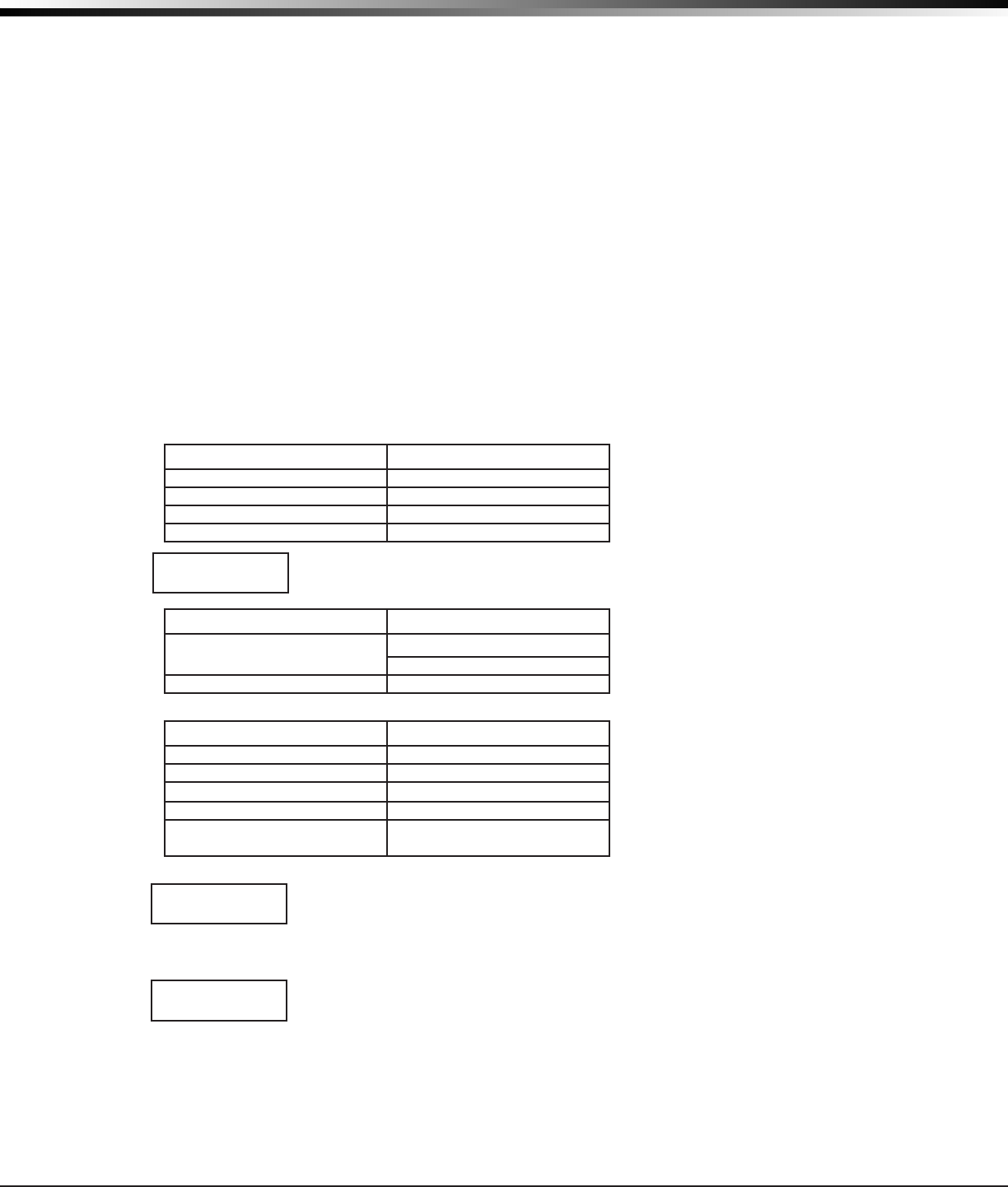
XTLplus Installation and Programming Guide Digital Monitoring Products
41
APPENDIX
Panel Settings
Pressing a select key displays the MAC Address, Serial Number, Frequency Offset, Panel Model, and Firmware
Version.
MAC Address
The MAC address is the panel on-board network hardware address. Press any select key to display the
panel MAC address.
Serial Number
This number is the panel serial number. Reference this number for date-of-manufacture, hardware
version, etc. Press the COMMAND key to view the next option.
Frequency Offset
This menu option displays the frequency offset of the panel.
Panel Model
This menu option displays the panel model number.
Firmware Version
This menu option displays the Firmware Version number of the panel and date it was released.
Communication Status
This option tests the individual components of cellular or wireless network communication. The displayed
results are shown below.
Cellular Results:
Successful Display Failure Display
MODEM OPERATING NO MODEM FOUND
IDENTIFIED NO SIM CARD
TOWER DETECTED NO TOWER
REGISTERED NOT REGISTERED
This displays the cellular signal strength of the nearest tower for the SIM card carrier.
The
▐
’s represent the signal strength 0-7. Select YES to continue through the remaining
component tests. Select NO to stop testing and return to the COMM STATUS option.
Successful Display Failure Display
CONNECTED CONNECT ERROR
NOT ACTIVATED
COMM PATH GOOD NO ACK RECEIVED
Wireless Results:
Successful Display Failure Display
LINK OK LINK ERROR
DHCP OK DHCP ERROR
GATEWAY FOUND NO GATEWAY
DEST FOUND NO DESTINATION
COMM PATH GOOD NOT CONNECTED
NO ACK RECEIVED
Cellular Signal Strength (CELL SIGNAL)
This option provides a way to test the cellular signal strength of the nearest tower
for the cellular carrier. Press any select key to display cell signal strength. The X’s
represent the numerical value of the cell signal strength in -dBm. The
▐
’s represent the
signal strength 0-7.
Cell Roaming Indicator
The Cellular Signal Strength option in the panel’s Diagnostic menu contains a roaming
indicator. When the 265C Cellular Communicator is roaming or not in contact with a
Verizon owned tower, ROAM will be displayed on the top line of the keypad along with
the signal strength. To perform the cellular activation process from a keypad, the 265C MUST be in contact
with a Verizon owned tower. If the cellular communicator is in contact with a tower owned by another
network, ROAM and the signal strength displays, but activation cannot be completed. This feature can be
used as a diagnostic tool to troubleshoot activation issues.
SIGNAL:▐▐▐▐▐▐▐
CONTINUE?NOYES
-XX dBm
SIGNAL:▐▐▐▐▐▐▐
ROAM-XXdBm
SIGNAL:▐▐▐▐▐▐▐
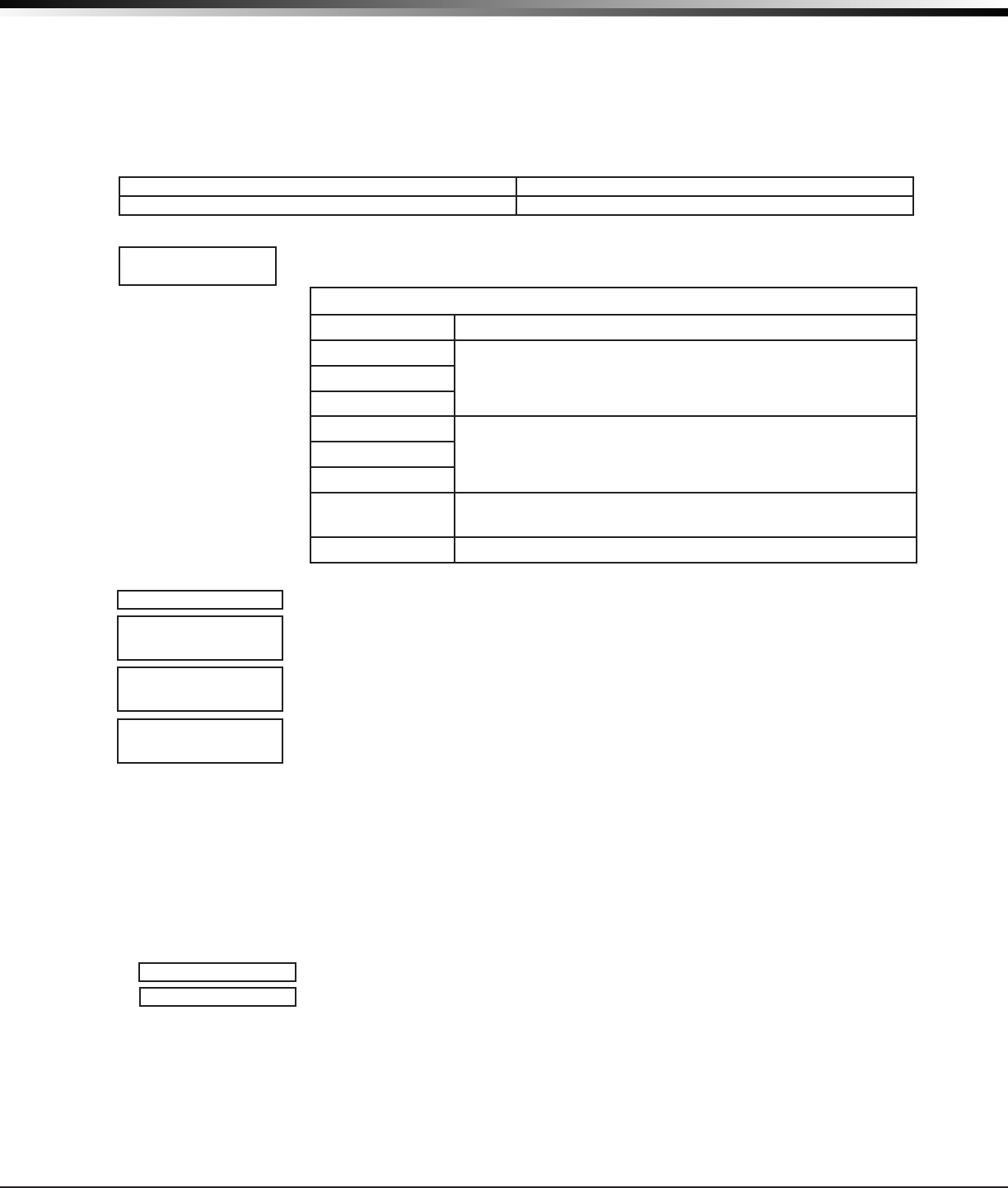
Digital Monitoring Products XTLplus Installation and Programming Guide
42
APPENDIX
Activate Cell
Note: If the 265C Cellular Communicator has not been previously activated, Automatic Cellular Activation
is performed when the panel powers up or is reset. Activate Cell (discussed below) is only necessary when
Automatic Cellular Activation is not successful and communication was not established.
To begin the cellular activation for a 265C CDMA Cellular Communicator, verify that the 265C MEID has been
added for the panel using Remote Link or by calling Customer Service (1-800-641-4282). At the keypad, press
any select key when ACTIVATE CELL is displayed on the keypad. When the SURE NO YES? conrmation menu
appears press the select key beneath YES to complete the cellular activation.
Successful Display Failure Display
CELL ACTIVATED NOT ACTIVATED
Wi-Fi Signal Strength (Wi-Fi SIGNAL)
This option tests the signal strength of the selected SSID. Press any select key to
display Wi-Fi signal strength. The
▐
’s represent the signal strength 0-7.
Wi-Fi Signal Strength
Number of Bars Indication
7
Good Signal (Excellent for consistent operation)6
5
4
Average Signal (Expect consistent operation)3
2
1 Weak Signal (Will not operate reliably. Relocate Wi-Fi
equipment or add a Wi-Fi extender for better reception.)
0 No Signal
Z-Wave Test Option
This feature allows the installer to test
XTLplus
communication with Z-Wave
devices. A successful test indicates a response from a device. Press any select key
to view the Z-Wave Device List.
Press COMMAND to advance through each Z-Wave device and press any select key
to begin the test on the device displayed.
The name of the device displays above the device number. The current number of
successful communications followed by the total number of attempts displays to
the right of the device number. The test stops after 99 attempts.
Press COMMAND to view the nal number of successful communications.
Exiting the Diagnostics program
Press the COMMAND key until STOP displays. Press any select key. The keypad returns to the Status
List display.
36.5 Using the Walk Test
The XTLplus panel provides a walk test feature that allows a single technician to test all the protection
devices connected to zones on the system. Conduct the Walk Test within 30 minutes of resetting the panel.
The Walk Test automatically ends if no zones are tripped for 20 minutes. TEST IN PROGRESS displays at all
keypads. When ve minutes remain, TEST END WARNING displays. If any areas are armed the Walk Test does
not start and SYSTEM ARMED displays.
Walk Test
To conduct the Walk Test, reset the control panel by pressing the RESET button
then wait one minute. From the keypad, enter the code 8144. The keypad displays
WALK TEST.
WLS (Wireless Check-in Test) - Select WLS to automatically test 1100 Series
wireless transmitter communications. Includes all wireless devices except key fobs
and transmitters programmed for a supervision time of 0 (zero).
PIR (Wireless PIR Walk Test) - The PIR Walk Test allows the installer to verify the
1126 and 1127 operation. When enabled, the 1126 LED ashes each time motion is
detected for up to 30 minutes. This is a local test only and no messages are sent to
the Central Station.
SIGNAL
▐▐▐▐▐▐▐
HOMENET123
TEST ZWAVE
DEVICELIST:
HALLWAYLIGHT
HALLWAYLIGHT
LIGHT020/0
HALLWAYLIGHT
99/99SUCCESSFUL
WALKTEST
STDWLSPIR

XTLplus Installation and Programming Guide Digital Monitoring Products
43
APPENDIX
Trip Counter For DMP Wireless Check-in Test (WLS)
Displays the number of wireless zones that automatically communicate a
supervisory check-in message.
• The number of zones that check in. (XXX in the example).
• The total number of wireless zones programmed for supervision that should
check in. (ZZ in the example).
END - Select END to stop the Wireless Check-in Test. When the test ends or
a 20-minute time-out expires, normal wireless zone processing returns. If all
transmitters check-in, both numbers will match within three (3) minutes. If a
transmitter has multiple zones (1101, 1114, etc.), all zones will be included in the
counts. Failed wireless zones then display on the keypad.
Test End Warning
When no zones have been tripped and ve minutes remain on the 20 minute Walk Test
timer, the keypad displays TEST END WARNING and the keypad tones. If no additional
test zone trips occur, the test ends and a nal Sensor Reset automatically occurs. The
System Test End message is sent to the receiver along with Verify and Fail messages
for each zone under WALK test. Faulted zones then display on the keypad.
Failed Zones Display
Each zone that did not trip at least once during the Walk Test displays on the keypad
that initiated the test. Any Fire (FI) Panic (PN) or Supervisory (SV) 24-hour zone
that is faulted at the end of the Walk Test displays a trouble condition for that zone
regardless of the message programmed for the open or short condition of the zone
and a zone trouble is sent to the receiver. Press the COMMAND key to display the next
failed zone.
For the Wireless Check-in Test, failed wireless zones display only on the keypad.
Zone Verify/Fail reports are not sent to the central station receiver for the
wireless checkin test.
36.6 Keypad Speaker Operation
When using LCD Keypads, the panel provides distinct speaker tones from the keypad for Fire, Burglary, Zone
Monitor, and Prewarn events. The list below details the conditions under which the speaker is turned on and
off for each event.
Fire On - Fire zone alarm and Bell Output are ON.
Off - Alarm Silence or briey when a key is pressed.
Burglary On - Burglary zone alarm and Bell Output and is ON.
Off - Alarm Silence or briey when a key is pressed.
Zone Monitor On - One time only when a monitored zone is tripped.
Off - After one tone.
Prewarn On - During Entry Delay.
Off - When Entry Delay expires, when a Valid Code is entered, or when a key is pressed.
36.7 Cross Zoning
Caution must be taken when cross zoning devices to ensure that the Cross Zone Time is long enough to allow
an intruder to trip both devices before it expires. A Cross Zone Time that is too short may allow an intruder
to trip the devices and allow only a zone fault report be sent to the central station.
When a Cross Zoned zone trips, a FAULT report is sent to the SCS-1R Receiver. When two Cross Zoned zones
trip within the Cross Zone Time, both zones send ALARM signals to the receiver. For example, if zones 1 and
2 are Cross Zoned zones, and only zone 1 trips, a FAULT report is sent to the receiver for zone 1. If zone 1
trips and zone 2 trips within the Cross Zone Time, an ALARM report is sent to the receiver for zone 1 and
zone 2.
Note: To operate correctly, all cross-zone zones need to be programmed as the same zone type.
WALKTEST
TRIPS:XXX END
TEST END WARNING
SOUTHLOBBY
ZONE:10 -FAIL

Digital Monitoring Products XTLplus Installation and Programming Guide
44
APPENDIX
36.8 Zone Type Descriptions
This section describes applications for the default zone types in Zone Information programming.
NT (Night Zone) - Controlled instant zone used for perimeter doors and windows and interior devices such as
PIRs and glassbreak detectors.
DY (Day zone) - Used for emergency doors or re doors to sound the keypad buzzer and display the zone
name when the zone is faulted. Day zones also will send alarm reports to the receiver during the system’s
armed periods.
EX (Exit zone) - Initiates the entry delay timer when its assigned area is fully armed. Also, can initiate an
exit delay timer to allow a user to exit an area after the arming process has started.
PN (Panic zone) - Used for connecting to mechanical devices that allow a user to signal an emergency alarm.
Panic zones can provide either a silent or audible alarm with or without reporting to a central
station receiver.
EM (Emergency zone) - These are used for reporting medical or other non-panic emergencies to the
central station.
SV (Supervisory zone) - Used to provide 24-hour zone supervision. Typical applications are high water, and
low and high temperature gauges.
FI (Fire zone) - Used for any type of powered or mechanical re detection device. Typical applications are
for smoke detectors, sprinkler ow switches, manual pull stations, and beam detectors.
FV (Fire Verify zone) - Used primarily for smoke detector circuits to verify the existence of an actual re
condition. When a Fire Verify zone initiates an alarm, the panel performs a Fire Reset. If any Fire zone
initiates an alarm within 120 seconds after the reset, an alarm is indicated. If an alarm is initiated after 120
seconds, the cycle is repeated.
A1 and A2 (Auxiliary 1 and Auxiliary 2) - These zones are similar to a Night zone and are typically used to
protect restricted areas within a protected premises. Auxiliary 2 zones do not appear in the Status List.
AR (Arming zone) - Allows you to connect a keyswitch to a zone and use it to arm and disarm the system.
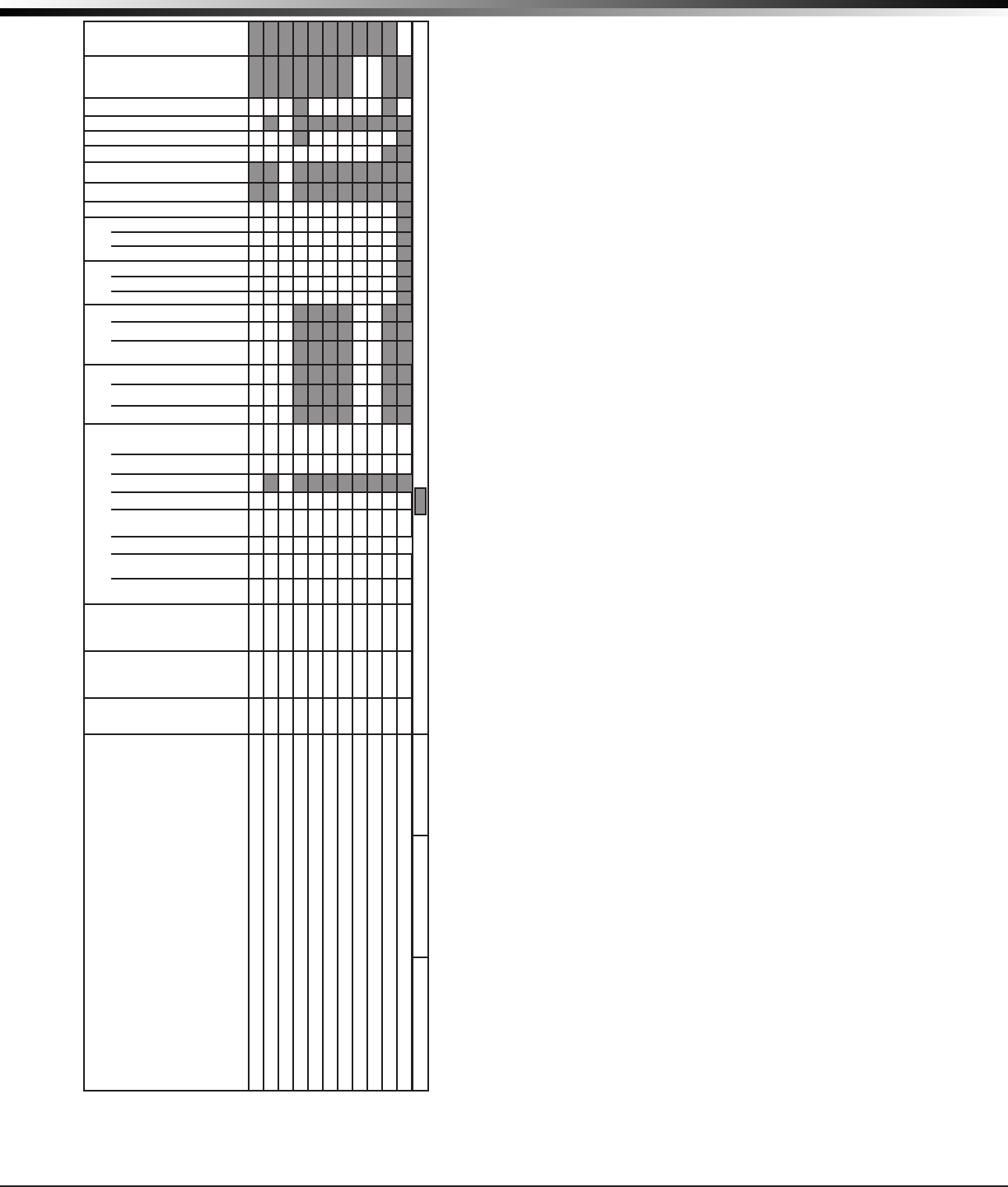
XTLplus Installation and Programming Guide Digital Monitoring Products
45
APPENDIX
36.9 Zone Type Defaults
The XTLplus panel contains 11 default zone types that
provide the most commonly selected functions for their
applications. All zone types can be customized by changing
the variable options listed below.
Key Fob - Indicates if a DMP key fob is programmed.
Type - These are the abbreviations displayed on the keypad
for the zone types.
Area - For a ALL/PERIM or HOME/SLEEP/AWAY system,
this is either Interior, Bedroom, or Perimeter. For an AREA
system use 1 to 6.
Wireless - 1100 Series Wireless options.
Contact - Indicates if the Universal Transmitter is
programmed to use the internal or external contact.
External Contact N/O? - Identies whether externally
installed contacts are programmed as a normally
open (N/O) or normally closed (N/C) circuit. Y = N/O
Contacts. N = N/C Contacts.
1114 Contact - Indicates if the 1114 Zone Expander is
programmed for contact(s) 1, 2, 3, or 4.
Supervision Time - Selects the number of minutes for
DMP wireless supervision.
1142 LED Operation - Identies DMP 1142 Wireless Two-
Button transmitter LED operation.
Disarm/Disable - Disables zone tripped messages from
1103 Transmitters and 1126/1127 PIRs while disarmed.
PIR Pulse Count - Selects the number of pulse counts
the 1126/1127 uses before sending a short message.
Sensitivity - Sets sensitivity for the 1126/1127 PIR.
Message - A = alarm report, T = trouble report,
L = local with no report, — (dash) = no report.
Output - 51 to 54 and 61 to 64 wireless outputs or wireless
key fob zones.
Action - This selects the type of relay output:
S = steady, P = pulse, M = momentary, and F = follow
Swinger Bypass - The zone can be automatically bypassed
after a programmed number of trips.
Prewarn - This selects the keypad address that sounds the
entry prewarn for this zone.
Entry Delay - Selects the entry delay timer used
for this zone.
Priority - Requires this zone to be in a normal condition
before the area can be armed.
Trafc Count - Provides the number of zone trips per area
for Night and Exit type zones in a disarmed state.
Zone Audit Days - Number of days allowed to elapse without
a zone being tripped before a message is sent.
Receiver Routing - This selects the routing option for
Auxiliary 1 or Auxiliary 2 zone types.
Style - The abbreviations that display on the keypad for
arming zone style. TGL = Toggle,
ARM = Arm only, DIS = Disarm only
STEP = Wireless arming, MNT = Maintain
Style
TGL
ARM
DIS
STEP
MNT
TGL
* Outputs = 31 to 34, 41 to 44, or F1-F20. = This function not available for this zone type.
Receiver Routing
NORM
1
2
BOTH
NORM
NORM
Zone Audit Days
0
to
99
0
0
0
0
0
0
0
0
0
Trafc Count
N
or
Y
N
N
Priority
N
or
Y
N
N
N
N
N
N
N
N
N
Cross Zone
N
or
Y
N
N
N
N
N
N
N
N
N
Entry Delay
1
or
2
1
Prewarn
1
to
5
1-5
Swinger
N
or
Y
Y
Y
Y
N
N
N
N
N
N
N
Armed
Short
Action
S
P
M
F
S
S
S
S
S
S
S
S
S
S
Output *
0
0
0
0
0
0
0
0
0
0
Message
A
T
L
–
A
A
A
A
A
A
A
A
A
A
Armed
Open
Action
S
P
M
F
S
S
S
S
S
S
S
S
S
S
Output *
0
0
0
0
0
0
0
0
0
0
Message
A
T
L
–
A
A
A
T
T
T
T
T
T
T
Disarmed
Short
Action
S
P
M
F
S
S
S
S
S
Output *
0
0
0
0
0
Message
A
T
L
–
–
T
–
A
A
Disarmed
Open
Action
S
P
M
F
S
S
S
S
S
Output *
0
0
0
0
0
Message
A
T
L
–
–
T
–
T
T
DMP Wireless
Sensitivity
Low
or
High
Low
Low
Low
Low
Low
Low
Low
Low
Low
Low
Low
PIR Pulse Count
2
or
4
4
4
4
4
4
4
4
4
4
4
4
Disarm-Disable
N
or
Y
Y
Y
LED Operation
N
or
Y
Y
Y
Y
Y
Y
Y
Y
Y
Y
Y
Y
Supervision
Time
0
3
60
240
240
240
240
240
240
240
240
240
240
240
240
1114 Contact
1
2
3
4
1
1
1
1
1
1
1
1
1
1
1
External
Contact N/O?
N
or
Y
N
N
N
N
N
N
N
N
N
N
N
Contact
INT
or
EXT
INT
INT
INT
INT
INT
INT
INT
INT
INT
INT
INT
Area
INT
BDRM
PERIM
or
1 to 6
Type
-- NT
DY EX
FI PN
EM SV
A1 A2
FV AR
NT
DY
EX
FI
PN
EM
SV
A1
A2
FV
AR
Key
Fob
N
or
Y
N
N
N
N
N
N
N
N
N
N
N
XTLplus Zone Information
Assign Area and Disarmed condition for NT, DY, EX, A1, and A2 only.
Assign Prewarn and Entry Delay for EX only.
Assign Style for AR only.
Assign 31 to 34 or 41 to 44 to Key Fobs.
Wireless output modules can be assigned to 31 to 34 and 41 to 44.
Supervision Time of 3 minutes can only be used with Zone Types FI, FV and SV.
Zone Type Defaults
NIGHT
DAY
EXIT
FIRE
PANIC
EMERGENCY
SUPERVISORY
AUXILIARY 1
AUXILIARY 2
FIRE VERIFY
ARMING
Serial NumberZone Name
Zone #

Digital Monitoring Products XTLplus Installation and Programming Guide
46
APPENDIX
36.10 Common Keypad Messages
Message Meaning Possible Solutions
INVALID CODE The user code you have entered is not
recognized by the system. Check the user code and try again.
CLOSING TIME The schedule has expired but the
system has not been armed.
Users still on the premise should arm the system
or extend the schedule to a later time.
KEYPAD NAME - NOPWR Wireless keypad is not getting proper
power.
Check that AC/DC transformer is plugged in
correctly.
AC TROUBLE The system AC is low or missing. Check that the AC connections are good.
BATTERY TROUBLE The System battery is either low or
missing.
Check that the battery connections are good
and the battery is still good.
SYSTEM TROUBLE or
SERVICE REQUIRED
There is a problem with one or more
components in the system. Press the RESET button for 1-2 seconds.
SYSTEM BUSY The system is performing another task
with a higher priority.
Wait a few moments for the system to complete
the task. If the message displays for a long
period of time, the processor could be locked
up.
TRANSMIT FAIL
The panel has attempted to
communicate with the central station
10 times and has not succeeded.
Verify your communication type, account
number, and IP address.
ENTER CODE (When
entering Programming)
A lockout code has been programmed
for the panel. Enter the lockout code.
Listed Compliance Specications
37.1 Introduction
The programming and installation specications contained in this section must be completed when installing
the XTLplus in accordance with any of the ANSI/UL or SIA burglary standards. Additional specications may
be required by a particular standard.
37.2 Use Marking
Commercial Central Station, Household Burglar Control Unit.
37.2 Locations and Wiring
Locations and wiring methods shall be in accordance with the National Electrical Code, ANSI/NFPA 70 and the
Standard for Installation and Classication of Burglar and Holdup Alarm Systems, UL 681.
37.3 NFPA 72
This equipment should be installed in accordance with Chapter 29 of the National Fire Alarm Code,
ANSI/NFPA 72, (National Fire Protection Association, Batterymarch Park, Quincy, MA 02269). Printed
information describing proper installation, operation, testing, maintenance, evacuation planning, and repair
service is to be provided with this equipment. Warning: Owner’s instruction notice, not to be removed by
anyone except occupant.
37.4 Types Of Service
Suitable for Central Station Burglar. Suitable for Household Fire and Household Burglar. Test weekly. The
XTLplus has not been evaluated by Intertek for Household Fire.
37.5 Police Station Phone Numbers
The XTLplus must not be programmed to communicate with a police station.
37.6 Bypass Reports
The bypass reports must be programmed as YES for all listed burglary applications.
37.7 System Testing
The system must be tested once per week and Checked by a qualied technician once every three (3) years.
COMPLIANCE

XTLplus Installation and Programming Guide Digital Monitoring Products
47
COMPLIANCE
37.8 FCC Notice
This device complies with Part 15 of the FCC Rules. Operation is subject to the following two conditions: (1) This
device may not cause harmful interference, and (2) this device must accept any interference received, including
interference that may cause undesired operation.
This equipment complies with the FCC RF radiation exposure limits set forth for an uncontrolled environment. This
equipment should be installed and operated with a minimum distance of 20cm between the radiator and any part
of your body.
This device must not be collocated or operating in conjunction with any other antenna or transmitter.
Household Burglar-Alarm System Units
ANSI/UL 1023
38.1 Bell Cutoff
The bell cutoff time cannot be less than 4 minutes.
38.2 Entry Delay
The maximum entry delay used must not be more than 45 seconds.
38.3 Exit Delay
The maximum exit delay used must not be more than 60 seconds.
38.4 Wireless External Contact
When used, the External Contact of 1101, 1102, or 1106 transmitters must be programmed Normally Closed.
38.5 Wireless Supervision Time
The Zone Information Supervision Time cannot be set to 0 (zero).
38.6 Wireless Audible Annunciation
The Wireless Audible option must be selected as DAY for residential applications.
38.7 Panel location
Mount panel inside protected area.
38.8 Test Frequency
The Test Frequency option must be programmed to send a report at least once every 30 days.
Central Station Burglar Alarm Units
ANSI/UL 1610
39.1 Supervision
Commercial Burglary is provided when the Check-in and Fail Time time is set to 3 minutes.
39.2 Remote Disarm
REMOTE DISARM must be programmed as NO.
39.3 Central Station
MESSAGE TO TRANSMIT programming for zones must not be set to LOCAL (L).

Digital Monitoring Products XTLplus Installation and Programming Guide
48
COMPLIANCE
Household Fire Warning System
ANSI/UL 985 NFPA 72 Specications
40.1 Bell Output Denition
The bell output of the Model XTLplus must be programmed to operate steady on burglary alarms and
temporal on re alarms.
40.2 Household System
An alarm sounding device must be installed indoors so that it is clearly heard in all sleeping areas.
40.3 Wireless Supervision Time
The Zone Information Supervision Time must be 3 minutes for re devices.
40.4 Wireless Fire Verication
When used, the Model 1161 and 1162 wireless smoke detectors must not be programmed as Fire Verication
(FV) zone type.
40.5 Battery Standby
For listed applications, the panel must have 24 Hour battery standby operation. The Model XTL+BAT3500
battery should be used for re installations.
40.6 Test Frequency
The Test Frequency option must be programmed to send a report at least once every 30 days.

XTLplus Installation and Programming Guide Digital Monitoring Products
49
REVISIONS
False Alarm Reduction Programmable Options
ANSI/SIA CP-01-2010
41.1 Shipping Defaults and Recommended Programming
SIA CP-01 FEATURE
PARAGRAPH # AND
DESCRIPTION
DMP PROGRAMMING
GUIDE LT-1434
SECTION #
REQUIREMENT RANGE SHIPPING
DEFAULT
RECOMMENDED
PROGRAMMING*
4.2.2.1 Exit Time 28.6 Exit Delay Required
(Programmable) 45 sec. - 250 sec. 60
Seconds 60 Seconds
4.2.2.2 Progress
Annunciation
33.14 Prewarn
Address Allowed Individual keypads may
be disabled per zone
All
keypads
enabled
All keypads enabled
4.2.2.3 Exit Time Restart 28.6 Exit Delay Required Option For re-entry during exit
time Enabled Enabled
4.2.2.5 Auto Stay Arm on
Unvacated Premises
28.17 Occupied
Premise - See Install
Guide
Required Option
(except for remote
arming)
Occupied Premise NO/
YES option Enabled
Enabled Yes
for Residential
Applications
4.2.4.4 Exit Time and
Progress Annunciation/
Disable - for Remote Arm
Not Available on
Remote Arming Allowed Option
Progress Annunciation
Always disabled for
Remote Arming
Not
Available
Remote Arming not
allowed for CP-01
installations.
4.2.3.1 Entry Delay(s) 28.5 Entry Delay
Required
(Programmable) Only
use Entry Delay 1. Do
not use Entry Delay 2.
30 sec. – 240 Sec. ** 30
Seconds
At least 30
Seconds **
4.2.5.1 Abort Window –
for Non-Fire Zones 36.2 Transmit Delay Required Option Disable by zone or zone
type
Enabled
NT DY EX
Zone
Enabled
4.2.5.1 Abort Window
Time – for Non-Fire
Zones
36.2 Transmit Delay Required
(Programmable)
20 sec., 30 sec., or
40 sec. **
30
Seconds
At least 20
Seconds **
4.2.5.1.2 Abort
Annunciation 36.2 Transmit Delay Required Option Annunciate that no
alarm was transmitted Yes Ye s
4.2.5.4.1 Cancel
Annunciation
Always Enabled - Not
Programmable Required Option
Annunciate that a
Cancel was transmitted
(S49)
Always
Enabled Yes
4.2.6.1 & 4.2.6.2 Duress
Feature
User Code + 1 =
Ambush Code Not
Available
Allowed Option
No 1 + derivative of
another user code/no
duplicates with other
user codes
Code +1
Always
Disabled
Not Programmable
4.3.1 Cross Zoning 33.16 Cross Zone Required Option Yes/No Zone
Programming No
Enabled using
two or more
programmed zones
4.3.1 Programmable
Cross Zoning Time 28.7 Cross Zone Time Allowed 4 sec. - 250 sec. 0 Seconds Per walk path in
protected premises
4.3.2 Swinger Shutdown Not Available —
Always On Required 1-6 trips 2 trips 2 trips
4.3.2 Swinger Shutdown
Disable 33.13 Swinger Bypass Allowed For non-police response
zones Yes Enabled (all zones)
4.3.3 Fire Alarm
Verication 33.5 Zone Type Required Option FV Type Zone No
Yes as required
(unless sensors can
self verify)
4.6.3 System Test 36.5 Walk Test Allowed Test all protection
devices N/A N/A
4.6.5 Communications 36.5 Walk Test Not Allowed N/A N/A N/A
* Programming at installation may be subordinate to other listed requirements for the intended application.
** For listed Installations, combined Entry Delay and Transmit Delay should not exceed 1 minute.
Local Bell
All non-re zones such as Night, Day, Exit, Aux 1 and Aux 2 must be programmed for local bell enabled with a bell
cutoff time set to a minimum of 6 minutes to provide a cancel window of 5 minutes or greater. This does not apply
to manually operated zone types such as Panic and Emergency.
The requirements are superseded by any requirements for Commercial Burglar, Household Fire Warning, or
Household Burglar applications.
Minimum Installation Requirements: SIA CP-01-2010 minimum system installation requirements include an XTLplus,
an 1135 Wireless Siren, a 9000 Series Wireless keypad, and communication to an SCS-1R receiver.

800-641-4282
INTRUSION • FIRE • ACCESS • NETWORKS
www.dmp.com 2500 North Partnership Boulevard
Designed, Engineered and
Manufactured in Springfield, Missouri
Springeld, Missouri 65803-8877
LT-1434 1.02 © 2016 Digital Monitoring Products, Inc.
16205
Certications
FCC Wireless Receiver AND Z-Wave Approvals
FCC ID: CCKPC0181
FCC Wi-Fi Network Approvals
FCC ID: VW4-ATWINC1500
ANSI/UL 1023 Household Burglar
ANSI/UL 1610 Central Station Burglar
ANSI/UL 1635 Digital Burglar
ANSI/UL 985 Household Fire
Ordering Information
XTL+W 900MHz with Wi-Fi
XTL+Z 900MHz with Z-Wave
XTL+WZ 900MHz with Wi-Fi and Z-Wave
Accessories
265C CDMA Cellular Communicator
372-500-W 12VDC Nominal Power Supply (ST-12500W)
XTL+BAT800/8 3.8VDC Nominal Lithium, 800mAh Battery
XTL+BAT3500/8 3.8VDC Nominal Lithium, 3500mAh Battery
Revisions to This Document
This section explains the changes made to this document during this revision. It lists the date and identies
the change(s) made, the related section number and section heading, and a summary of the change.
Ver. Section Number and Heading Quick Explanation of Changes
1.01 Entire Document Initial Release
1.02 6.1, 6.2, Certications 3500mAh Battery, ANSI/UL 985 Household Fire Listing