Digital Security Controls 11GS255SM Wireless Alarm Communicator User Manual
Digital Security Controls Ltd. Wireless Alarm Communicator
User Manual

GS2055
HSPA/2G WIRELESS ALARM COMMUNICATOR
TL255GS
ETHERNET/INTERNET ALARM COMMUNICATOR
Installation Manual
v2.5X
Warning: This manual contains information on limitations regarding product use and function and information on the limitations
as to liability of the manufacturer.
NOTE: This manual covers the following models for the North America:
GS2055-NA
TL255GS-NA
GS2055-SM-NA
TL255GS-SM-NA
29008218R001_NOVA_TL255GS_GS2055_V.2.5X_IM_ENG_NA_UL_ULC_FCC_IC_dft_03
D: - MM (dts: 9/15-10:24)
- DN/em______________

2G Alarm Communicator Installlation Manual
2
Warning: Installer Please Read Carefully . . . . . . . . . . . . . . . . . . . . . . . . . . . . . . . . . . . . . . . . . . . . . . . . . . . . . . . . . . . . . . . . 3
General Information. . . . . . . . . . . . . . . . . . . . . . . . . . . . . . . . . . . . . . . . . . . . . . . . . . . . . . . . . . . . . . . . . . . . . . . . . . . . . . . 4
Communicator Technical Specifications . . . . . . . . . . . . . . . . . . . . . . . . . . . . . . . . . . . . . . . . . . . . . . . . . . . . . . . . . . . . . . . . 5
Features . . . . . . . . . . . . . . . . . . . . . . . . . . . . . . . . . . . . . . . . . . . . . . . . . . . . . . . . . . . . . . . . . . . . . . . . . . . . . . . . . . . . . . . 5
UL/ULC Installation Requirements . . . . . . . . . . . . . . . . . . . . . . . . . . . . . . . . . . . . . . . . . . . . . . . . . . . . . . . . . . . . . . . . . . . . 5
Ratings . . . . . . . . . . . . . . . . . . . . . . . . . . . . . . . . . . . . . . . . . . . . . . . . . . . . . . . . . . . . . . . . . . . . . . . . . . . . . . . . . . . . . . . . 6
Hardware Compatibility . . . . . . . . . . . . . . . . . . . . . . . . . . . . . . . . . . . . . . . . . . . . . . . . . . . . . . . . . . . . . . . . . . . . . . . . . . . . 6
Software Compatability . . . . . . . . . . . . . . . . . . . . . . . . . . . . . . . . . . . . . . . . . . . . . . . . . . . . . . . . . . . . . . . . . . . . . . . . . . . . 6
Communicator Pre Installation Configuration. . . . . . . . . . . . . . . . . . . . . . . . . . . . . . . . . . . . . . . . . . . . . . . . . . . . . . . . . . . . 6
Connect24™ Account and SIM card Activation . . . . . . . . . . . . . . . . . . . . . . . . . . . . . . . . . . . . . . . . . . . . . . . . . . . . . . . . . . . 6
Encryption. . . . . . . . . . . . . . . . . . . . . . . . . . . . . . . . . . . . . . . . . . . . . . . . . . . . . . . . . . . . . . . . . . . . . . . . . . . . . . . . . . . . . . 7
Communicator Configuration with SCW . . . . . . . . . . . . . . . . . . . . . . . . . . . . . . . . . . . . . . . . . . . . . . . . . . . . . . . . . . . . . . . 7
Installing CAT 5 Cable (TL255GS only) . . . . . . . . . . . . . . . . . . . . . . . . . . . . . . . . . . . . . . . . . . . . . . . . . . . . . . . . . . . . . . . . 7
Communicator Reset . . . . . . . . . . . . . . . . . . . . . . . . . . . . . . . . . . . . . . . . . . . . . . . . . . . . . . . . . . . . . . . . . . . . . . . . . . . . . . 8
Establishing a Communication Channel with the SCW Panel. . . . . . . . . . . . . . . . . . . . . . . . . . . . . . . . . . . . . . . . . . . . . . . . . . 8
Label Programming for SMS Message . . . . . . . . . . . . . . . . . . . . . . . . . . . . . . . . . . . . . . . . . . . . . . . . . . . . . . . . . . . . . . . . . . 9
Programming Options Sections
ETHERNET/Cellular Programming Options . . . . . . . . . . . . . . . . . . . . . . . . . . . . . . . . . . . . . . . . . . . . . . . . . . . . . . . . . . . 10
System Options . . . . . . . . . . . . . . . . . . . . . . . . . . . . . . . . . . . . . . . . . . . . . . . . . . . . . . . . . . . . . . . . . . . . . . . . . . . . . . . . .10
Programming Options. . . . . . . . . . . . . . . . . . . . . . . . . . . . . . . . . . . . . . . . . . . . . . . . . . . . . . . . . . . . . . . . . . . . . . . . . . . . . 12
Communications Reporting Codes. . . . . . . . . . . . . . . . . . . . . . . . . . . . . . . . . . . . . . . . . . . . . . . . . . . . . . . . . . . . . . . . . . . . 15
Ethernet Receiver 1 Options . . . . . . . . . . . . . . . . . . . . . . . . . . . . . . . . . . . . . . . . . . . . . . . . . . . . . . . . . . . . . . . . . . . . . . . . 17
Ethernet Receiver 2 Options . . . . . . . . . . . . . . . . . . . . . . . . . . . . . . . . . . . . . . . . . . . . . . . . . . . . . . . . . . . . . . . . . . . . . . . . 17
Ethernet Options . . . . . . . . . . . . . . . . . . . . . . . . . . . . . . . . . . . . . . . . . . . . . . . . . . . . . . . . . . . . . . . . . . . . . . . . . . . . . . . . 18
Cellular Receiver 1 Options . . . . . . . . . . . . . . . . . . . . . . . . . . . . . . . . . . . . . . . . . . . . . . . . . . . . . . . . . . . . . . . . . . . . . . . . 18
Cellular Receiver 2 Options . . . . . . . . . . . . . . . . . . . . . . . . . . . . . . . . . . . . . . . . . . . . . . . . . . . . . . . . . . . . . . . . . . . . . . . . 19
Cellular Options. . . . . . . . . . . . . . . . . . . . . . . . . . . . . . . . . . . . . . . . . . . . . . . . . . . . . . . . . . . . . . . . . . . . . . . . . . . . . . . . . 19
[634] Error Code . . . . . . . . . . . . . . . . . . . . . . . . . . . . . . . . . . . . . . . . . . . . . . . . . . . . . . . . . . . . . . . . . . . . . . . . . . . . . . . . 25
. . . . . . . . . . . . . . . . . . . . . . . . . . . . . . . . . . . . . . . . . . . . . . . . . . . . . . . . . . . . . . . . . . . . . . . . . . . . . . . . . . . . . . . . . . . . . 28
System Information (Read Only) . . . . . . . . . . . . . . . . . . . . . . . . . . . . . . . . . . . . . . . . . . . . . . . . . . . . . . . . . . . . . . . . . . . . . 30
System Reset Defaults . . . . . . . . . . . . . . . . . . . . . . . . . . . . . . . . . . . . . . . . . . . . . . . . . . . . . . . . . . . . . . . . . . . . . . . . . . . . 30
Programming Worksheets Sections
Ethernet/Cellular Programming Worksheets. . . . . . . . . . . . . . . . . . . . . . . . . . . . . . . . . . . . . . . . . . . . . . . . . . . . . . . . . . . . 34
System Options . . . . . . . . . . . . . . . . . . . . . . . . . . . . . . . . . . . . . . . . . . . . . . . . . . . . . . . . . . . . . . . . . . . . . . . . . . . . . . . . .34
Programming Options. . . . . . . . . . . . . . . . . . . . . . . . . . . . . . . . . . . . . . . . . . . . . . . . . . . . . . . . . . . . . . . . . . . . . . . . . . . . . 34
Ethernet Receiver 1 Options . . . . . . . . . . . . . . . . . . . . . . . . . . . . . . . . . . . . . . . . . . . . . . . . . . . . . . . . . . . . . . . . . . . . . . . . 34
Ethernet Receiver 2 Options . . . . . . . . . . . . . . . . . . . . . . . . . . . . . . . . . . . . . . . . . . . . . . . . . . . . . . . . . . . . . . . . . . . . . . . . 35
Ethernet Options . . . . . . . . . . . . . . . . . . . . . . . . . . . . . . . . . . . . . . . . . . . . . . . . . . . . . . . . . . . . . . . . . . . . . . . . . . . . . . . . 35
Cellular Receiver 1 Options . . . . . . . . . . . . . . . . . . . . . . . . . . . . . . . . . . . . . . . . . . . . . . . . . . . . . . . . . . . . . . . . . . . . . . . . 35
Cellular Receiver 2 Options . . . . . . . . . . . . . . . . . . . . . . . . . . . . . . . . . . . . . . . . . . . . . . . . . . . . . . . . . . . . . . . . . . . . . . . . 35
Cellular Options. . . . . . . . . . . . . . . . . . . . . . . . . . . . . . . . . . . . . . . . . . . . . . . . . . . . . . . . . . . . . . . . . . . . . . . . . . . . . . . . . 35
[634] Error Code . . . . . . . . . . . . . . . . . . . . . . . . . . . . . . . . . . . . . . . . . . . . . . . . . . . . . . . . . . . . . . . . . . . . . . . . . . . . . . . . 35
System Information (Read Only) . . . . . . . . . . . . . . . . . . . . . . . . . . . . . . . . . . . . . . . . . . . . . . . . . . . . . . . . . . . . . . . . . . . . . 37
System Reset Defaults . . . . . . . . . . . . . . . . . . . . . . . . . . . . . . . . . . . . . . . . . . . . . . . . . . . . . . . . . . . . . . . . . . . . . . . . . . . . 37
End User Licence Agreement . . . . . . . . . . . . . . . . . . . . . . . . . . . . . . . . . . . . . . . . . . . . . . . . . . . . . . . . . . . . . . . . . . . . . . . 38
Limited Warranty. . . . . . . . . . . . . . . . . . . . . . . . . . . . . . . . . . . . . . . . . . . . . . . . . . . . . . . . . . . . . . . . . . . . . . . . . . . . . . . . 39
TABLE OF CONTENTS
29008218R001_NOVA_TL255GS_GS2055_V.2.5X_IM_ENG_NA_UL_ULC_FCC_IC_dft_03

2G Alarm Communicator Installlation Manual Warning: Installer Please Read Carefully
3
WARNING: INSTALLER PLEASE READ CAREFULLY
Note to Installers
The Warnings on this page contain vital information. As the only individual in
contact with system users, it is the installer’s responsibility to bring each item in
this Warning to the attention of all users of this system.
System Failures
This system has been carefully designed to be as effective as possible. There are
circumstances, however, involving fire, burglary, or other types of emergencies
where it may not provide protection. Any alarm system of any type may be com-
promised deliberately or may fail to operate as expected for a variety of reasons.
Some, but not all, of the reasons may be:
Access by Intruders
Intruders may enter through an unprotected access point, circumvent a sensing
device, evade detection by moving through an area of insufficient coverage, dis-
connect a warning device, or interfere with or prevent the proper operation of the
system.
Component Failure
Although every effort has been made to make this system as reliable as possible,
the system may fail to function as intended due to the failure of a component.
Compromise of Radio Frequency (Wireless) Devices
Signals may not reach the receiver under all circumstances which could include
metal objects placed on or near the radio path or deliberate jamming or other
inadvertent radio signal interference.
Criminal Knowledge
This system contains security features which were known to be effective at the
time of manufacture. It is possible for persons with criminal intent to develop
techniques which reduce the effectiveness of these features. It is important that
your security system be reviewed periodically to ensure that its features remain
effective and that it is updated or replaced if it is found that it does not provide the
protection expected.
Failure of Replaceable Batteries
This system’s wireless transmitters have been designed to provide several years
of battery life under normal conditions. The expected battery life is a function of
the device environment, usage, and type. Ambient conditions such as high
humidity, high or low temperatures, or large temperature fluctuations may reduce
the expected battery life. While each transmitting device has a low battery moni-
tor which identifies when the batteries need to be replaced, this monitor may fail
to operate as expected. Regular testing and maintenance will keep the system in
good operating condition.
Inadequate Installation
A security system must be installed properly in order to provide adequate protec-
tion. Every installation should be evaluated by a security professional to ensure
that all access points and areas are covered. Locks and latches on windows and
doors must be secure and operate as intended. Windows, doors, walls, ceilings
and other building materials must be of sufficient strength and construction to
provide the level of protection expected. A reevaluation must be done during and
after any construction activity. An evaluation by the fire and/or police department
is highly recommended if this service is available.
Inadequate Testing
Most problems that would prevent an alarm system from operating as intended
can be found by regular testing and maintenance. The complete system should be
tested weekly and immediately after a break-in, an attempted break-in, a fire, a
storm, an earthquake, an accident, or any kind of construction activity inside or
outside the premises. The testing should include all sensing devices, keypads,
consoles, alarm indicating devices, and any other operational devices that are part
of the system.
Insufficient Time
There may be circumstances when the system will operate as intended, yet the
occupants will not be protected from an emergency due to their inability to
respond to the warnings in a timely manner. If the system is remotely monitored,
the response may not occur in time to protect the occupants or their belongings.
Motion Detectors
Motion detectors can only detect motion within the designated areas as shown in
their respective installation instructions. They cannot discriminate between
intruders and intended occupants. Motion detectors do not provide volumetric
area protection. They have multiple beams of detection and motion can only be
detected in unobstructed areas covered by these beams. They cannot detect
motion which occurs behind walls, ceilings, floor, closed doors, glass partitions,
glass doors or windows. Any type of tampering whether intentional or uninten-
tional such as masking, painting, or spraying of any material on the lenses, mir-
rors, windows or any other part of the detection system will impair its proper
operation.
Passive infrared motion detectors operate by sensing changes in temperature.
However their effectiveness can be reduced when the ambient temperature rises
near or above body temperature or if there are intentional or unintentional sources
of heat in or near the detection area. Some of these heat sources could be heaters,
radiators, stoves, barbeques, fireplaces, sunlight, steam vents, lighting and so on.
Power Failure
Control units, intrusion detectors, smoke detectors and many other security
devices require an adequate power supply for proper operation. If a device oper-
ates from batteries, it is possible for the batteries to fail. Even if the batteries have
not failed, they must be charged, in good condition and installed correctly. If a
device operates only by AC power, any interruption, however brief, will render
that device inoperative while it does not have power. Power interruptions of any
length are often accompanied by voltage fluctuations which may damage elec-
tronic equipment such as a security system. After a power interruption has
occurred, immediately conduct a complete system test to ensure that the system
operates as intended.
Security and Insurance
Regardless of its capabilities, an alarm system is not a substitute for property or
life insurance. An alarm system also is not a substitute for property owners, rent-
ers, or other occupants to act prudently to prevent or minimize the harmful effects
of an emergency situation.
Smoke Detectors
Smoke detectors that are a part of this system may not properly alert occupants of
a fire for a number of reasons, some of which follow. The smoke detectors may
have been improperly installed or positioned. Smoke may not be able to reach the
smoke detectors, such as when the fire is in a chimney, walls or roofs, or on the
other side of closed doors. Smoke detectors may not detect smoke from fires on
another level of the residence or building.
Every fire is different in the amount of smoke produced and the rate of burning.
Smoke detectors cannot sense all types of fires equally well. Smoke detectors
may not provide timely warning of fires caused by carelessness or safety hazards
such as smoking in bed, violent explosions, escaping gas, improper storage of
flammable materials, overloaded electrical circuits, children playing with
matches, or arson.
Even if the smoke detector operates as intended, there may be circumstances
when there is insufficient warning to allow all occupants to escape in time to
avoid injury or death.
Telephone Lines
If telephone lines are used to transmit alarms, they may be out of service or busy
for certain periods of time. Also an intruder may cut the telephone line or defeat
its operation by more sophisticated means which may be difficult to detect.
Warning Devices
Warning devices such as sirens, bells, horns, or strobes may not warn people or
waken someone sleeping if there is an intervening wall or door. If warning
devices are located on a different level of the residence or premise, then it is less
likely that the occupants will be alerted or awakened. Audible warning devices
may be interfered with by other noise sources such as stereos, radios, televisions,
air conditioners, other appliances, or passing traffic. Audible warning devices,
however loud, may not be heard by a hearing-impaired person.
29008218R001_NOVA_TL255GS_GS2055_V.2.5X_IM_ENG_NA_UL_ULC_FCC_IC_dft_03
Keypad Data Display 2G Alarm Communicator Installlation Manual
4
Domain Name Service (DNS) programming is not permitted in UL/ULC listed systems.
KEYPAD DATA DISPLAY
•Section-Toggle Options: The number is displayed when Toggle is ON, the number is not displayed when Toggle is OFF. (e.g., Tog-
gle Options displays: “[
--
3
--
6
--
]”. Options 3 and 6 are ON, all others are OFF). Pressing keys 1 through 8 will alternately turn the
Toggle ON and OFF.
•HEX/Decimal Data: Values that are provided with two defaults, separated by a / character, use the format: hexadecimal followed by
decimal equivalent (e.g., Default [0BF5/3061]). Hexadecimal numbers are shown, with all leading zeroes, to the full field length
defined for the number.
ENTERING DATA FROM KEYPAD
To enter data at the keypad, press the number key, from the table below, to select the character that you want. Pressing the number key
repeatedly will scroll through the characters available for that key. Press the [*] key and use
[<] [>] keys to scroll to one of the following
selections: (Press [*] to select the Option.)
•ASCII Entry. Use this mode to enter ASCII characters from the keypad.
•Clear to End. This selection will clear the remainder of the display.
•Clear Display.This selection will completely erase all entries on the display.
•Change Case. Toggles between upper/lower depending on current selection.
NOTE: The “0” on the keypad is used to delete characters.
ENTERING ASCII CHARACTERS
To enter American Standard Code for Information Interchange (ASCII) characters at the keypad, perform the following:
1. Press [*] and use [<] [>] keys to scroll to “ASCII Entry”.
2. Press [*] to select ASCII entry mode.
3. Use the
[<] [>] keys to scroll to display the ASCII character you want to use and press [*] to accept.
4. Press [*] to exit ASCII character entry mode and return to normal entry.
NOTE: Authorized access to Connect24 (GS2055/TL255GS) or DLS IV is required to modify any Ethernet/Cellular Programming
Section. Specific panel Sections must be configured for proper operation of the Communicator with the panel.
MOUNTING CONSIDERATIONS
The Cellular/Ethernet Communicator is fixed, wall-mounted unit and shall be installed in the location specified in these instructions.
The equipment enclosure must be fully assembled and closed, with all the necessary screws/tabs and it must be secured to a wall before
operation.
Internal wiring must be routed in a manner that prevents:
• Excessive strain on wire and on terminal connections,
• Interference between power limited and non power limited wiring,
• Loosening of terminal connections, or
• Damage of conductor insulation.
WARNING: NEVER INSTALL THIS EQUIPMENT DURING A LIGHTNING STORM!
The Installer must instruct the System user on each of the following items:
• This manual shall be used in conjunction with the Alarm controller manual; All the safety instructions specified within that manual
shall be observed.
• Do not attempt to service this product. Opening or removing covers may expose the user to dangerous
voltages or other risks.
• Any servicing shall be referred to trained service person only.
• Use authorized accessories only with this equipment.
Cellular Coverage for Alarm Communicator Operation
The HSPA/2G performance of the GS2055 and TL255GS Alarm Communicators depends greatly on Cellular network coverage. The
SCW (with internal Alarm Communicator) should not be mounted in the final location without first ensuring that Cellular radio recep-
tion is adequate for communication using the HSPA/2G paths. Perform the “Communicator Placement Test” on page 9.
GENERAL INFORMATION
Table 1: Data Entry at Keypad
Key Value Key Value Key Value
1 1-A-B-C 4 4-J-K-L 7 7-S-T-U
2 2-D-E-F 5 5-M-N-O 8 8-V-W-X
3 3-G-H-I 6 6-P-Q-R 9 9-Y-Z-0
29008218R001_NOVA_TL255GS_GS2055_V.2.5X_IM_ENG_NA_UL_ULC_FCC_IC_dft_03

2G Alarm Communicator Installlation Manual General Information
5
GENERAL INFORMATION
All versions of the HSPA/2G and Ethernet Alarm Communicator, operate on a HSPA/2G network and are housed inside the Self Con-
tained Wireless (SCW) 9055/9057. The Communicators use an Internal Antenna only.
Each version of Alarm Communicators covered by this Installation Manual are described below:
GS2055: A High Speed Packet Access/Global System for Mobile (HSPA/2G) wireless Alarm Communicator that sends alarm communica-
tion to Sur-Gard System I, II, III (SG-DRL3IP), and IV (SG-DRL4IP) central station receivers via a HSPA/2G digital cellular network.
TL255GS: Is a dual-path Cellular/Ethernet Alarm Communicator that sends alarm communication to Sur-Gard System I, II, III, and IV
central station receivers through Ethernet/Internet or a HSPA/2G digital cellular network.
The dual path Communicator can be used as either a backup or primary Communicator. The Communicator supports Internet Protocol
(IP) transmission of panel and internal events over Ethernet/Internet and/or HSPA/2G.
For North America the following model names are available: GS2055-NA, TL255GS-NA, GS2055-SM-NA, and TL255GS-SM-NA.
CAUTION:
• Do not stay close to the equipment during device operation and to do not touch any exposed wires and other conductive surfaces,
• Recycle the battery according to the local rules and regulations.
NOTE: Prior to installation of the GS2055 or TL255GS Communicator, confirm with your local carrier that the HSPA/2G network is
available and active in the area where the Communicator will be installed, and that the location provides a radio signal strength
that is adequate for uninterrupted service.
FEATURES
UL/ULC INSTALLATION REQUIREMENTS
• For ULC Residential fire and burglary applications the GS2055/TL255GS can be used as primary communication channel via either
Cellular or Ethernet (as applicable) or as a back-up in conjunction with the Digital Alarm Communicator Transmitter (DACT). Test
transmission every 24hours shall be enabled on each channel.
• For UL Residential fire and burglary applications the GS2055/TL255GS can be used as primary communication channel via either
Cellular or Ethernet, or as a back-up in conjunction with the DACT. (30 day test transmission is required on each channel).
COMMUNICATOR FREQUENCY BANDS FOR NORTH AMERICA
COMMUNICATOR TECHNICAL SPECIFICATIONS
• 128-bit Advanced Encryption Standard (AES) encryption via HSPA/2G and Ethernet/Internet.
• Activating, initializing and remote programming through Connect 24.
• Back up or primary HSPA/2G alarm communication.
• Does not require an external HSPA/2G antenna.
• Ethernet LAN/WAN 10/100 BaseT (TL255GS only).
• Full event reporting to central station.
• Fully redundant Ethernet/Internet and HSPA/2G Dual-path Alarm Communication (TL255GS only).
• Individual Ethernet and/or HSPA/2G Periodic test transmission.
• 2-way audio (listen-in feature) provided over Cellular.
• Integrated call routing.
• Remote Firmware upgrade capability of the Communicator and Panel Firmware via Ethernet and/or HSPA/2G radio.
• Dual-Band Operation: 850 MHz, and 1900 MHz. (North America only)
• CID and SIA format reporting.
• Subscriber Identity Module (SIM) card included with Communicator. (North America only)
• Supervision heartbeats via HSPA/2G and/or Ethernet/Internet.
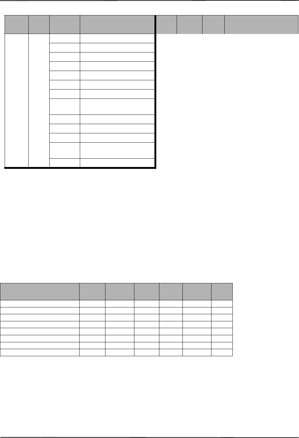
Table 2: 2G Frequency Bands
Transmit Direction Cellular 850 North America PCS 1900 North America
Transmit Frequency 824 MHz to 849 MHz 1850 MHz to 1910 MHz
Receive Frequency 869 MHz to 894 MHz 1930 MHz to 1990 MHz
Table 3: 2G Frequency Bands
Transmit Direction UMTS 850 North America,
International UMTS 1900 North America
Transmit Frequency 824 MHz to 849 MHz 1850 MHz to 1910 MHz
Receive Frequency 869 MHz to 894 MHz 1930 MHz to 1990 MHz
29008218R001_NOVA_TL255GS_GS2055_V.2.5X_IM_ENG_NA_UL_ULC_FCC_IC_dft_03
Ratings 2G Alarm Communicator Installlation Manual
6
RATINGS
HARDWARE COMPATIBILITY
Products or components of products, which perform communications functions only shall comply with the requirements applicable to
communications equipment as specified in UL60950 or CAN/CSA-C22.2 No. 60950-1, Information Technology Equipment - Safety -
Part 1: General Requirements. Where network interfaces are internal to the control unit or receiver, compliance to CAN/CSA-C22.2
No. 60950-1 is adequate. Such components include, but are not limited to: hubs; routers; NIDs; Third party communications service
providers; DSL modems; and Cable modems.
SOFTWARE COMPATABILITY
The Communicator is compatible with the following software:
• Connect24 Using: Simple Messaging System (SMS) Protocol.
• Connect24 Remote Flash. Using: Internet Protocol (IP) using Trivial File Transfer Protocol (TFTP).
CONNECT24™1 ACCOUNT AND SIM CARD ACTIVATION
(Before Installation)
Installation of the Communicator requires activation with Connect24 before operation. Dealer application forms and additional infor-
mation on the Connect24 Voice Response Unit (VRU) and graphical user interface (GUI) can be found at http://www.Connect24.com
or by telephone at: USA 1-888-251-7458 or CANADA 1-888-955-5583.
IMPORTANT: Prior to installing a GS2055 or TL255GS Communicator, contact your monitoring station to determine if it is a master
re-seller or visit http://www.Connect24.com to become an authorized dealer. In either instance, you will receive a Profile Number,
Installer ID Number, and an Installer Password. Perform the following pre installation:
1. Retrieve the installer account and password from the master reseller, or from Connect24 directly.
2. Connect your browser to the Connect 24 website at: http://www.Connect24.com or call VRU number.
3. Log in to the Connect24 website using your installer account and password.
4. Perform the following steps in a Connect24 session to activate the SIM card and initialize programming:
a. Navigate to the Initialize an account section.
b. Select Profile (This information will be provided by the master reseller or by Connect24).
c. Select Product Module.
d. Enter the SIM card number.
e. Click Next then enter in all relevant information as required.
f. Confirm all information is entered correctly before submitting.
5. Repeat Step 4 to program another SIM card (i.e. another Subscriber), or log out from Connect24.
6. When you are at the physical installation site, the Communicator will automatically connect and download its programming from
Connect24 once the unit is initialized.
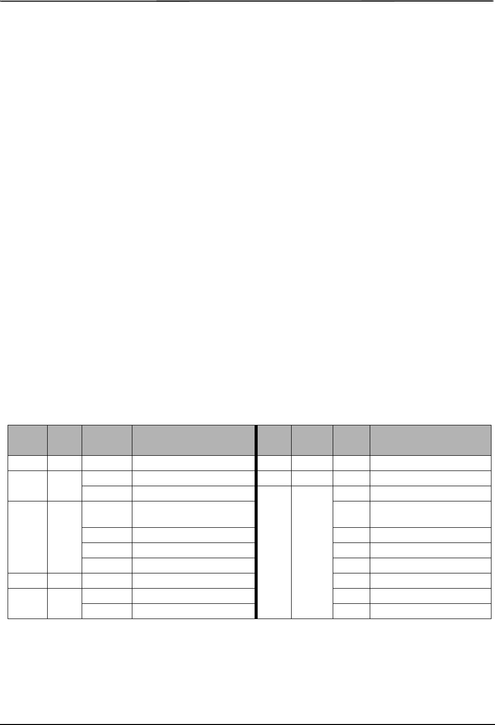
Table 4: Communictor Electrical Ratings
Model GS2055
Cellular Only TL255GS
Ethernet and Cellular
Power Supply Ratings
Input Voltage 3.5 / 3.9 / 4.2 VDC (min / NOM / MAX) from the SCW panel
Current Consumption 75 mA 100 mA
Standby Current (@ 3.7V) 75 mA 100 mA
Alarm (Transmitting) Current) 400 mA @ 3.7V during transmission
Antenna Specifications
Dual band Antenna See Table 2 and Table 3
Environmental Specifications
Operating Temperature 0°C - 49°C (32°F- 120°F)
Humidity 5% ~ 85% relative humidity, non-condensing
Mechanical Specifications
Board Dimensions (mm) 109 x 110
Weight (grams) 60 65
Table 5: Compatibility
Communicator Receiver/
ControlPanel Description
GS2055
TL255GS
Receiver
SG System I, v1.14+
SG System II, v2.11+
SG-DRL3-IP, v2.3+
SG-DRL4-IP, v1.2+
Control Panel SCW9055/SCW9057 V1.00
COMMUNICATOR PRE INSTALLATION CONFIGURATION
1. Connect24, DSC, and DLS IV are Registered Trademarks of Tyco International Ltd. and its respective Companies. All Rights Reserved.
29008218R001_NOVA_TL255GS_GS2055_V.2.5X_IM_ENG_NA_UL_ULC_FCC_IC_dft_03
2G Alarm Communicator Installlation Manual Encryption
7
NOTE: Following initial installation, you can log in to the Connect24 website at any time to re-configure the Communicator remotely,
using the account created for this installation. For more information, refer to the Connect24 website.
Before leaving the installation site, the Communicator GS2055 or TL255GS shall be connected via an APPROVED (acceptable
to the local authorities) Network Interface Device (NID) (e.g., for UL Installations, U60950 listed NID). All wiring shall be per-
formed according to the local electrical codes.
ENCRYPTION
The Communicator uses 128 Bit AES Encryption. Encryption can only be enabled from the monitoring station receiver. Each receiver
can independently have encryption enabled or disabled. When encryption is enabled, the central station will configure the device to
encrypt communications the next time the Communicator module performs a communication to that receiver.
NOTE: Packets will start being encrypted only after the next event is sent to that receiver, or if the unit is restarted.
NOTE: The Alarm Communicator is installed in the
SCW prior to shipment by Digital Security Controls
(DSC). The Factory Installation includes insertion of
the SIM card. The SCW should not be mounted in its
final location without performing a Communicator
Test to ensure adequate HSPA/2G coverage for the
GS2055 and TL255GS Alarm Communicators
INSTALLATION LOCATION
The Communicator shall be installed in an indoor
location only.
This HSPA/2G/Ethernet Communicator shall be
installed by Service Personnel only. (Service Person is
defined as a person having the appropriate technical
training and experience necessary to be aware of haz-
ards to which that person may be exposed in perform-
ing a task and can also take measures to minimize the
risks to that person or other persons). The Communi-
cator shall be installed and used within an environ-
ment that provides the pollution degree max 2, over
voltages category II, in non-hazardous, indoor loca-
tions only. This manual shall be used with the Installa-
tion Manual of the alarm control panel which is connected to the HSPA/2G/Ethernet Communicator. All instructions specified within
the control panel manual must be observed.
All the local rules imposed by local electrical codes shall be observed and respected during installation.
INSTALLING CAT 5 CABLE (TL255GS ONLY)
A Category 5 (CAT 5) ethernet cable must be run from a source with Ethernet/Internet
connectivity to the Communicator module, inside the Self Contained Wireless Control
Panel cabinet. The Communicator end of the cable must have an RJ-45 plug, which con-
nects to the Communicator’s RJ-45 jack. All requirements for installation of CAT5 eth-
ernet cable must be observed for correct operation of the Communicator, including, but
not limited to, the following:
• Do NOT strip off cable sheathing more than required for proper termination.
• Do NOT kink/knot cable.
• Do NOT crush cable with cable ties.
• Do NOT untwist CAT5 pairs more than 1.2cm (½”).
• Do NOT splice cable.
• Do NOT bend cable at right angles or make any other sharp bends.
NOTE: CAT5 specification requires that any cable bend must have a minimum 5 cm (2
in.) bend radius. Maximum length of CAT 5 cable is 100m (328 ft.).
NOTE: The Ethernet cable shall not be visible when the installation is complete unless
the install is a surface mount installation.
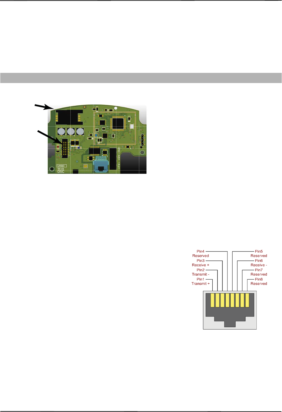
COMMUNICATOR CONFIGURATION WITH SCW
Figure 1: Communication Board Connection Points
RJ-45
SIM Card
PC-LINK
Use CAT 5 Cable Only
(TL255 and TL2553G Models)
DG009640
Ribbon Cable Connection
(16 Pins)
RJ-45 Connector
DG0009635
Figure 2: RJ-45 Pinout
29008218R001_NOVA_TL255GS_GS2055_V.2.5X_IM_ENG_NA_UL_ULC_FCC_IC_dft_03
Inserting/Removing the SIM Card 2G Alarm Communicator Installlation Manual
8
INSERTING/REMOVING THE SIM CARD
1.Remove the front cover of the SCW Control Panel to access SIM
card holder.
2.Remove power from the SCW and disconnect the backup battery
connections.
3.On the SIM card holder push gently to slide the cover towards
OPEN as indicated by the arrow on SIM holder. This will unlatch
the SIM card holder on the side furthest from edge of the Communi-
cator. See Figure 1.
4.Lift up the SIM card holder from the side that is not hinged.
NOTE: The SIM card can be damaged by bending or scratching contacts. Use caution when handling the SIM card.
5. Insert or remove the SIM card, noting the orientation of the notches on the SIM card and the SIM card holder.
6. When inserting a SIM card, insert the card in the proper orientation and gently push the SIM card holder down and slide the holder
as indicated by the arrow on SIM holder, to LOCK.
7. Apply AC power to panel, and replace the panel cover.
COMMUNICATOR RESET
The Communicator can be reset by cycling the power on the SCW.
ESTABLISHING A COMMUNICATION CHANNEL WITH THE SCW PANEL.
The Communicator interfaces to the SCW through a keyed 16 pin Ribbon cable. See Table 6 . The key prevents incorrect connection of
the ribbon cable connector to the SCW and Communicator. The pinout for the Ribbon cable is provided in the Table below:
Establishing a communication channel between the Communicator and the SCW is critical to ensuring the desired operation of the two
units. The following steps must be completed during the on-site installation. Program the following to ensure that the Communicator
and the panel will work together as intended.
Initial Programming of Communicator and SCW
1. Enter
[*][8][Installer Code] [Section Number]
for panel programming. Record any values that are modified from their default, in the
appropriate Programming Worksheets.
NOTE: When programming Toggle Options, the toggle is ON when the number is displayed and OFF when the number is not dis
played. (e.g., [1---5---], Toggle Options 1 and 5 are ON, all others are OFF).
2. Panel Section [167] Cellular/Ethernet Interface Communications ‘Wait for ACK’: Default value is: 060 seconds.
3. When the communicator is installed with the SCW panel, 4 telephone number are available to backup one another. You can set up
these 4 telephone numbers to perform in one of two ways: Backup dialling or Alternate dialling.
a. Backup dialling: each of the 4 telephone numbers will make 5 dialling attempts in turn, before an FTC trouble is displayed on the
keypad.
b. Alternate dialling: each telephone number makes 1 dialling attempt before moving on to the next number, cycling through each
of the 4 numbers for a total of 5 times each. If all 4 numbers fail the 5 attempts, an FTC trouble is displayed on the keypad.
4. Panel Sections [301], [302], [303], and [305] can be configured as Primary communication paths.
a. Panel Sections [302], [303], and [305] may also be configured for backup or redundant communications by using Panel Section(s)
[383] or [351] - [376]. Refer to the SCW panel Installation Manual for more information.
b. If a valid telephone number is programmed, communications will use Public Switched Telephone Network (PSTN). Entering a 4
digit hexadecimal value for a telephone number will change the call routing to the Communicator, as determined by the number
programmed:
DCAAF: Internal (All Receivers). Signals will be routed depending on Section [851] [006] programming.
DCBBF: Ethernet Receiver 1 (Primary). (Not available for GS2055).
DCCCF: Ethernet Receiver 2 (Backup). (Not available for GS2055).
NOTE: Add a single ‘F’ as a suffix to the 4 digit hex number to populate the unused remainder of the 32 character field.
5. Panel Section [350]: If any of the phone numbers have been programmed as DCAA, DCBB, DCCC, DCDD, or DCEE, panel Sec-
tion [350] must be set to [04] if SIA format or [03] if Contact ID (CID) format is used by control panel.
6. Panel Section [382]: Toggle Option [5], ‘GS/IP Module Enabled’, must be set to ON.
Table 6: Communicator Ribbon cable to SCW
Pin # Signal Pin # Signal
1 PC-Link TX 2 PC-Link RX
3 GND 4 Vref
5 Vref 6 GND
7 AUD-OUT_N 8 AUD-OUT_P
9 AUD-IN_P 10 AUD-IN_N
11 GND 12 SI
13 GND 14 SO
15 GND 16 Wall Tamper
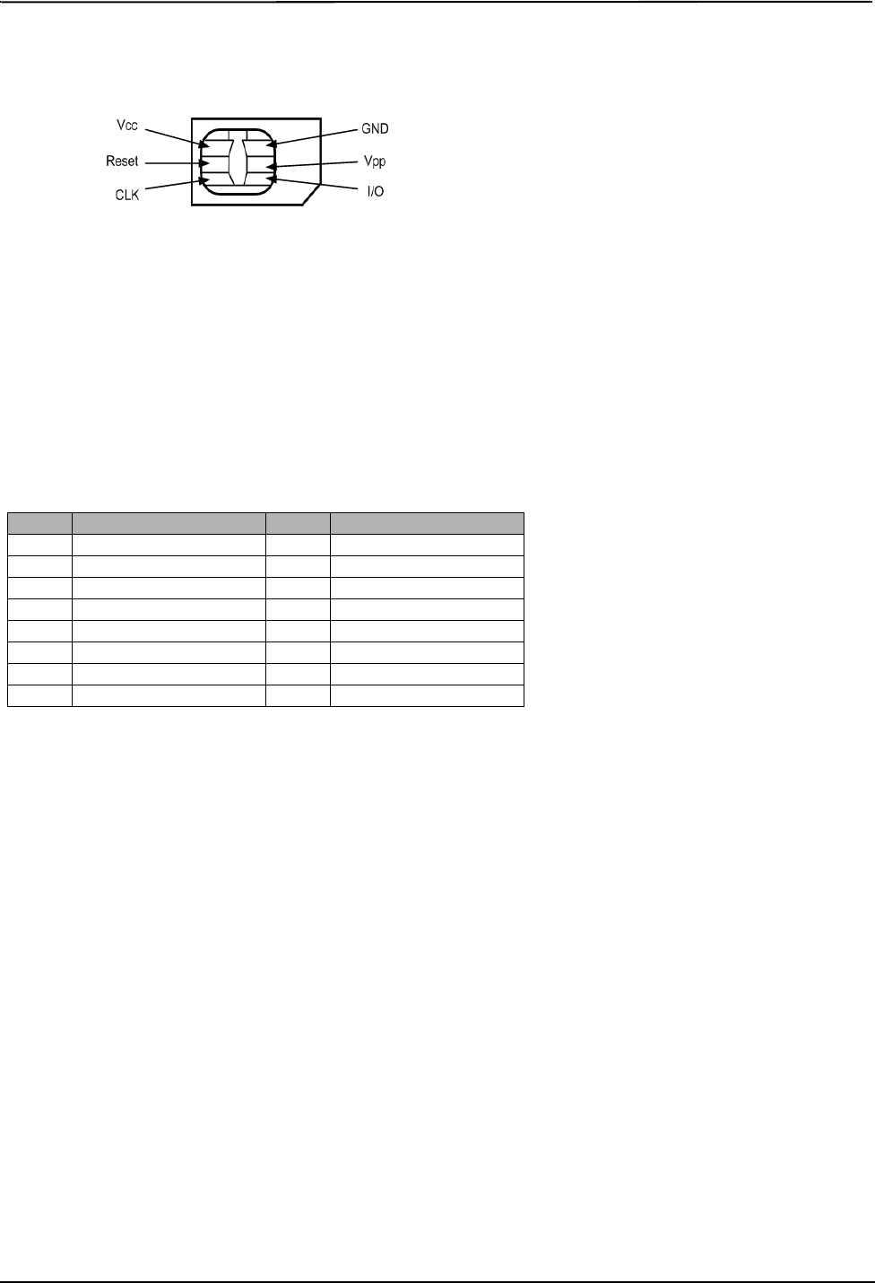
SIM Card Pinouts
DG0009396
Figure 3: SIM Card Pinouts
29008218R001_NOVA_TL255GS_GS2055_V.2.5X_IM_ENG_NA_UL_ULC_FCC_IC_dft_03

2G Alarm Communicator Installlation Manual SMS Command and Control Functions
9
7. Panel Section [401]: Toggle Option [1] must be set to ON in order to perform panel DLS session through Cellular or Ethernet data
channel.
NOTE: Keep a record of the SIM card telephone number, it is required by users for SMS Command and Control functions. (The num-
ber can be recorded in the Programming Worksheets Section of this document, under Option [996]) Due to the nature of the
SIM card activation process with Cellular network carriers, it can take up to 24 hours for SIM card activation to be complete.
SMS COMMAND AND CONTROL FUNCTIONS
SMS Command and Control is available on SCW9055/57 panels. Users can send SMS text messages from their mobile phone to the
GSM phone number assigned to their system. Commands are only accepted from telephone numbers that have been programmed in
Sections [311]-[318]. The system will reject messages sent from telephone numbers that are not on the programmed list.
When the received SMS text matches a valid Section message, the function is performed on the control panel. Text messages are not
case sensitive and extra spaces are ignored. A User Access Code may be required for some SMS messages.
The User can send just the partition number or the complete label.(e.g., “Away arm Partition 2 1234” is treated the same as
“away arm 2 1234 ”).
The SMS Message format is in 3 parts: Command, Partition Label (or only the partition number), and Access Code.
If an Access Code is included in the message, it is sent to the control panel for validation, along with the requested function.
If the panel is configured to require an Access Code and the code is not sent (or invalid) the panel will fail the function (unsuccessful).
If the panel fails the function, an SMS response message is sent to the user. The SMS response will echo the command sensat, followed
by the label “unsuccessful”. (e.g., “night arm partition 2 1234 unsuccessful”).
The partition label or partition number may be excluded from the SMS request in a single partition system (e.g., disarm 9123).
NOTE: The GSM phone number can be viewed in Section [851],[996], and/or [851],[229] or by User entering *6, then scrolling down
to “SMS Programming” and scrolling down to “Cellular phone No”.
LABEL PROGRAMMING for SMS MESSAGE
Programmable Labels can not be modified in Connect24, use DLS IV for label programming only, if labels need to be modified. Before
initiating remote programming, record your network’s Public IP Address and port for incoming DLS IV connections.
1. Run the DLS IV software on your computer. DLS IV will connect to the unit, using the Public IP address, and make an Ethernet con-
nection. If the Ethernet connection fails, DLS IV will report an error and prompt you to connect using Cellular.
NOTE: If required, download the DLS IV software from DSC: http://www.dsc.com/index.php?n=library#self. If you select Cellular
connection, DLS will request Connect24 to send an outgoing SMS message to the unit.
2. Connect24 will confirm that the account has DLS service and will provide the Public IP address and port number of the DLS server
in an SMS message.
3. Type the SMS message text into your cell phone and send it to the Communicator’s Cellular telephone number. Click OK.
NOTE: The Cellular phone number can be read from Communicator Section [851][996] and/OR [851][229].
4. SMS message will establish a connection to your computer’s DLS IV software (to change programming labels only).
5. Create an account for the panel/Communicator, select the Communicator type (e.g., SMS - TL255GS) and enter all relevant infor-
mation in SMS section.
NOTE: The Cellular telephone number will also be required by the user, to send SMS Interactive messages to their system.
6. Program the account information, then click Global Download and choose SMS as the Connection Type. Click OK.
7. The download path configured in Programming Section [005] Toggle Option[4] determines the Cellular or Ethernet path to be used.
COMMUNICATOR PLACEMENT TEST
(GS2055/TL255GS only)
1. Using the keypad enter the installer mode: * 8 [installer code] [850].
2. View and record the number of bars showing on the SCW LCD.
3. Compare with the number of bars indicated in the “CSQ Levels” column shown in Table 7 .
4. If 3 or more bars are shown, the location is GOOD and no further action is required.
5. If the location is BAD, move the SCW to various suitable locations until 3 or more bars are obtained
Table 7: Communicator CSQ Levels
Signal
Strength CSQ Level Signal Level dBm Installer Action
No Signal 0 -108.8 Check if Cellular coverage is active in your area.
1 Bar 1 to 4 -108d to -103 Location is BAD. Not suitable for Cellular operation.
2 Bars 5 to 6 -102 to -99 Location is FAIR. If the average signal strength is CSQ is 5, the system may not communicate
events successfully to the Monitoring Station. Installer should consider relocation, if possible.
3 Bars 7 to 10 -98d to -91 Location is GOOD.
4 Bars 11 to 13 -90 to -85 Location is GOOD
5 Bars 14 and higher -84 and higher Location is GOOD.
29008218R001_NOVA_TL255GS_GS2055_V.2.5X_IM_ENG_NA_UL_ULC_FCC_IC_dft_03

System Options 2G Alarm Communicator Installlation Manual
10
The Programming Sections described in this document can be viewed at the SCW LCD. To start programming enter: [*][8][installer
code] [851][# # # ], Where ### is the 3 digit Section number referenced in this section. The Programming Worksheets at the end of
this document can be used to record the new values when programming changes have been made from the default values.
Programming Sections are accessed through Connect24. Installers may review/record programming Options at the panel.
NOTE: Ethernet/Cellular Programming Sections accessed through the panel are for display purposes only. Configuration changes
must be done using Connect24.
SYSTEM OPTIONS
[001] Ethernet IP Address
Default (000.000.000.000)
Enter the IP address of the Communicator. Ensure that the IP address is unique to your Communicator on the local network. Format is 4
fields, each field is a 3 digit decimal number. Valid range: 000-255. If an IP address is programmed in this Section, the unit will operate
with Static IP (DHCP disabled). Sections [002] and [003] must also be programmed when using Static IP addresses.
NOTE: Default for this Section is Dynamic Host Configuration Protocol (DHCP) enabled. When enabled, the DHCP Server will set
values for: IP Address [001], Subnet Mask [002], and Gateway [003]. Programming an IP address in this Section will disable
DHCP (Static IP).
[002] Ethernet IP Subnet Mask
Default (255.255.255.000)
Enter the Ethernet IP Subnet Mask of the Communicator. Format is 4 fields, each field is 3 digits. Valid range: 000-255.
NOTE: If DHCP is enabled, the DHCP Server will assign the subnet mask for this Section and the
programmed value will be ignored.
[003] Ethernet Gateway IP Address
Default (000.000.000.000)
Enter the Ethernet Gateway IP address of the Communicator. The gateway IP address is required when a router is used on the local net-
work to reach the destination IP address specified in Section [001]. Format is 4 fields, each field is a 3 digit decimal number. Valid
range: 000-255.
NOTE: If DHCP is enabled, the DHCP Server will assign the Gateway IP address for this Section and the programmed value will be
ignored.
[004] Receiver Supervision Interval
Default (0087/135)
When receiver supervision is enabled (ON) in Section [005] Toggle Option [3], the unit sends heartbeats to Ethernet Receiver 1 or Cel-
lular Receiver 1 to test the communications path. Use this Section to set the interval time (in seconds) when heartbeats will be sent to
the receivers. Valid range 000A-FFFF seconds. If the programmed value is less than (000A/10) seconds, supervision is disabled.
•Receiver Window: This is the supervision timeout that must be configured at the central station receiver.
•Recommended Values: This is the recommended heartbeat interval that should be programmed into the Communicator.
• For ULC installations, the Daily test transmission must be enabled over each available communication channel Sections [125] and
[225]. When programming with Connect24, the recommended intervals will be programmed automatically when the required win-
dow is selected.
[005] System Toggle Options
[1] Ethernet Receiver 1 Supervised
Default (OFF)
(TL255GS only).
ON: Ethernet Receiver 1 will be supervised and heartbeats will be sent to Ethernet Receiver 1 based on the supervision interval pro-
grammed in Section [004].
OFF: Ethernet Receiver 1 will not be supervised. When disabled, heartbeat 1 is sent to the Ethernet receiver once every hour, regardless
of supervision type (heartbeat 1 or 2). The heartbeat is resent every 5 seconds until ACK. If no event or heartbeat ACK is received after
(Receiver Supervision Interval + 75 seconds), Supervisory trouble is indicated.
NOTE: Ethernet Receiver 2 can not be supervised.
[2] Cellular Receiver 1 Supervised
Default (OFF)
ON: Cellular Receiver 1 will be supervised and heartbeats will be sent to Cellular Receiver 1 based on the supervision interval pro-
grammed in Section [004]. If ACK to heartbeat is not received, it is retransmitted every 5 seconds. Failure to ACK 2 consecutive heart-
beats will reset the radio.
OFF: Cellular Receiver 1 will not be supervised. When disabled, heartbeat is not sent to the receiver. Supervisory trouble is indicated.
NOTE: Cellular Receiver 2 can not be supervised.
[3] Supervision Type
Default (OFF)
ON: Heartbeat 1 (Commercial Supervision). This supervision type is suitable for applications where swap detection is required on the
supervisory packet.
OFF: Heartbeat 2 (Residential Supervision). This supervision type is suitable for applications where supervision of the communication
path to the receiver is required. (no swap detection).
ETHERNET/CELLULAR PROGRAMMING OPTIONS
29008218R001_NOVA_TL255GS_GS2055_V.2.5X_IM_ENG_NA_UL_ULC_FCC_IC_dft_03

2G Alarm Communicator Installlation Manual System Options
11
NOTE: Commercial supervision is more data intensive than residential supervision and should only be used when required to meet the
approval for the installation.
[4] Primary Path
Default (OFF - TL255GS) (ON - GS2055)
ON: Cellular channel is the primary path. Ethernet channel is the secondary path, if it exists.
OFF: Ethernet channel is the primary path in a dual Communicator. Cellular channel is the secondary path.
[5] Redundant Communications
Default (OFF) (TL255GS only)
ON: Events will be communicated to Ethernet Receiver 1 and Cellular Receiver 1 at the same time. Events will be communicated to
Ethernet Receiver 2 and Cellular Receiver 2 at the same time. As long as the event is successfully communicated to 1 of the 2 paths
(Ethernet or Cellular) the Communicator will move on to the next event.
NOTE: Do not configure Ethernet Receiver 1 and Cellular Receiver 1 to communicate using a common receiver configuration (i.e.,
identical Receiver IP address and Receiver Remote Port). OFF: Events will be communicated to the receivers individually.
Toggle should be OFF when guaranteed message delivery to both receivers is required.
[6] Remote Firmware Upgrade
Default (ON)
ON: The Communicator module firmware can be remotely upgraded using the Ethernet/Cellular paths.
OFF: The Communicator module firmware can not be remotely upgraded. Local firmware upgrade is still possible.
[7] Alternate Test Transmissions
Default (OFF).
ON: When the periodic test transmission interval occurs, the test transmission will alternate between being sent to the primary and sec-
ondary receivers with each test transmission interval.
OFF: When the periodic test transmission interval occurs, the test transmission will be sent to the programmed receivers, based on the
settings of the periodic test transmission reporting codes.
[8] Cellular Low Signal Trouble.
Default (OFF)
This option masks the Low Signal trouble from the Cellular trouble event.
ON: A Cellular Trouble event is transmitted to receiver when the radio signal level falls below threshold level (average CSQ level is 5
or less).
OFF: A Cellular Trouble event is not transmitted to receiver when the radio signal level falls below threshold level (average CSQ level
is 5 or less).
[006] System Toggle Options 2
[1] Ethernet 1 Receiver Enabled.
Default (ON) (OFF for GS2055).
ON: Ethernet Receiver 1 is enabled.
OFF: Ethernet Receiver 1 is disabled.
[2] Ethernet 2 Receiver Enabled.
Default (ON) (OFF for GS2055).
ON: Ethernet Receiver 2 is enabled.
OFF: Ethernet Receiver 2 is disabled.
[3] Reserved. ( ).
[4] Cellular 1 Receiver Enabled.
Default (ON).
ON: Cellular Receiver 1 is enabled.
OFF: Cellular Receiver 1 is disabled.
[5] Cellular 2 Receiver Enabled.
Default (ON).
ON: Cellular Receiver 2 is enabled.
OFF: Cellular Receiver 2 is disabled.
[6] Reserved ( ).
[7] DLS Over Cellular.
Default (ON).
NOTE: Program this toggle as OFF if you want to completely disable DLS from using the Cellular path.
ON: DLS is enabled on the Cellular path.
OFF: DLS is disabled on the Cellular path.
NOTE: If this Toggle is OFF, DLS sessions will occur on the Ethernet path only, regardless of Primary Path set in Section [005] Toggle
Option [4]. If it is ON then the Communicator will connect to the Primary path first for DLS and if the session fails, the Sec-
ondary path will be used.
[8] Reserved ( ).
[007] DNS Server IP 1
Default (000.000.000.000)
Programming this Section is not permitted on a UL/ULC listed system.
29008218R001_NOVA_TL255GS_GS2055_V.2.5X_IM_ENG_NA_UL_ULC_FCC_IC_dft_03
Programming Options 2G Alarm Communicator Installlation Manual
12
Enter the IP address for DNS Server 1. Format is 4 fields, each field is a 3 digit decimal. Valid range: 000-255.
NOTE: If no value is programmed and DHCP is used, the DHCP Server will configure the address. If an address is programmed and
DHCP is used, the address that you program will be used instead of the DHCP address.
[008] DNS Server IP 2
Programming this Section is not permitted on a UL/ULC listed system.
Default (000.000.000.000)
Enter the IP address for DNS Server 2. Format is 4 fields, each field is a 3 digit decimal. Valid range: 000-255.
NOTE: If no value is programmed and DHCP is used, the DHCP Server will assign this value. If an address is programmed and DHCP
is used, the address that you program will be used instead of the DHCP address.
PROGRAMMING OPTIONS
[010] System Toggle Option
Default (Disable)
[1] This bit is used to enable/disable two way audio over 2G.
[011] Installer Code
Default (CAFE)
Program your installer code for this Communicator module. The installer code will be required when programming the Communicator
module. Valid range: 0000 - FFFF.
[012] DLS Incoming Port
Default (0BF6/3062)
The DLS Incoming Local Port (listening port) is the port DLS IV will use when connecting to the Communicator. If a router or gateway
is used, it must be programmed with a Transmission Control Protocol (TCP) port forward for this port to the Communicator module IP
address. Valid range: 0000 - FFFF.
[013] DLS Outgoing Port
Default (0BFA/3066)
The DLS Outgoing Port is used for outgoing session to DLS IV after an SMS request has been sent to the Communicator. Use this Sec-
tion to set the value of the local outgoing port. The value must be changed if the Communicator is located behind a firewall and must be
assigned a particular port number, as determined by your network administrator. In most cases, changing the default value or configur-
ing your firewall with this port is not required.
Valid range: 0000-FFFF.
NOTE: If Section [006] Toggle Option [7] is ON. DLS will use the Primary path for session. If Section [006] Toggle Option [7] is OFF
DLS will use the Ethernet path, if available.
[020] Time Zone
Default (00)
Use Column 2 (Offset Hours) to find your local Time Zone. Record the two digit HEX value from Column 1 (HEX Value) on the same
row. Program this HEX value for your Time Zone. Valid range is 00 - FF.
Table 8: World Wide Time Zones
HEX
Value Offset
Hours Std
Abbrev Location HEX
Value Offset
Hours Std
Abbrev Location
01 -12 BIT Baker Island Time 47 5.5 IST Indian Standard Time
05 -11 NUT Niue Time 48 5.75 NPT Nepal Time
SST Somoa Standard Time
49 6
XJT Xinjiang Standard Time
09 -10
HAST Hawaii-Aleutian Standard Time EKST East Kazakhstan Standard
Time
THAT Tahiti Time LKT Sri Lanka Time
TKT Tokelau Time VOST Vostok Time
CKT Cook Island Time OMSK Omsk Standard Time
0B -9.5 MIT Marquesas Island Time NOVT Novosibirsk Time
0D -9 AKST Alaska Standard Time BTT Bhutan Time
GIT Gambier Island Time BIOT British Indian Ocean Time
29008218R001_NOVA_TL255GS_GS2055_V.2.5X_IM_ENG_NA_UL_ULC_FCC_IC_dft_03

2G Alarm Communicator Installlation Manual Programming Options
13
11 -8
PST Pacific Standard Time 4B 6.5 CCT Cococ Islands Time
PST Pitcarirn Standard Time MMT Myanmar Time
CIST Clipperton Island Standard
Time
4D 7
CXT Christmas Island Time
15 -7 MST Mountain Standard Time KOVT Khovd Time
19 -6
CST Central Standard Time KRAT Krasnoyarsk Time
GALT Galapagos Time WIB Waktu Indonesia Bagian Barat
PIT Peter Island Time ICT Indochina Time
EAST Easter Island Standard Time BDT Bangladesh Standard Time
1D -5
EST Eastern Standard Time
51 8
AWST Australian Western Standard
Time
COT Colombia Time CST China Standard Time
ECT Ecuador Time HKST Hong Kong Standard Time
PET Peru Time WITA Waktu Indonesia Bagian Ten-
gah
ACT Acre Time TWT Taiwan Time
1F -4.5 VST Venezuela Standard Time SST Scarborough Shoal Time
21 -4
AST Atlantic Standard Time SIT Spratly Island Time
CLST Chile Standard Time SGT Singapore Time
BWST Brazil Western Standard Time PST Philippine Standard Time
SLT San Luis Time PIT Pratas Islands
PYT Paraguay Time PIT Parcel Island Time
JFST Juan Fernandez Island Standard
Time MYT Malaysia Time
GYT Guyana Time MNT Mongolia Time
FKST Falkland Island Standard Time MBT Macclesfield Bank Time
BOT Bolivia Time IRKT Irkutsk Time
23 -3.5 NST Newfoundland Standard Time BDT Brunei Time
25 -3
CGT Central Greenland Time ACIT Ashmore and Cartier Island
Time
ART Argentina Time 52 8.25 APO Apo Island Time
BRT Brazilia Time 54 8.75 ACWS
T
Australian Central Western
Standard Time
UYT Uruguay Standard Time
55 9
YAKT Yakutsk Time
SRT Suriname Time JST Japan Standard Time
ROTT Rothera Time KST Korea Standard Time
PMST St. Pierre & Miquelon Standard
Time WIT Waktu Indonesia Bagian Timur
GFT French Guiana Time TPT East Timor Time
29 -2
GST South Georgia and the South
Sandwich Islands PWT Palau Time
BEST Brazil Eastern Standard Time 57 9.5 ACST Australian Central Standard
Time
Table 8: World Wide Time Zones
HEX
Value Offset
Hours Std
Abbrev Location HEX
Value Offset
Hours Std
Abbrev Location
29008218R001_NOVA_TL255GS_GS2055_V.2.5X_IM_ENG_NA_UL_ULC_FCC_IC_dft_03

Programming Options 2G Alarm Communicator Installlation Manual
14
2D -1
EGT Eastern Greenland Time
59 10
AEST Australian Eastern Standard
Time
CVT Cape Verde Time GST Guam Standard Time
AZOST Azores Standard Time YAPT Yap Time
31 0
WET Western Europian Time VLAT Vladivostok Time
GMT Greenwich Mean Time (UTC) TRUT Truk Time
SLT Sierra Leone Time PGT Papua New Guinea Time
IST Ireland Standard Time DTAT District de Terre Adelie Time
35 1
CET Central Europian Time ChST Chamorro Standard Time
WAT Western Africa Time 5B 10.5 LHST Lord Howe Standard Time
BST British Summer Time
5D 11
KOST Kosare Standard Time
39 2
EET Eastern Europian Time NCT New Caledonia Time
CAT Central Africa Time VUT Vanuatu Time
SYT Syrian Standard Time SBT Solomon Island Time
SAST South Africa Standard Time PONT Phonpei Standard Time
IST Israel Standard Time MAGT Magadan Island Time
3D 3
MSK Moscow Standard Time 5F 11.5 NFT Norfolk Island Time
EAT Eastern Africa Time
61 12
NZST New Zealand Standard Time
AST Arabic Standard Time FJT Fiji Time
AST Arabia Standard Time WFT Wallis and Futuna Time
AST Al Manamah Standard Time TVT Tuvalu Time
3F 3.5 IRST Iran Standard Time PETT Petropavlovsk Time
41 4
AMST Armenia Standard Time NRT Nauru Time
SCT Seychelles Time MHT Marshall Island Time
GST Gulf Standard Time GILT Gilbert Island Time
SAMT Samara Time ANAT Anadyr Time
RET Reunion Time 64 12.75 CHAST Chatham Island Standard Time
MUT Mauritius Time 65 13 PHOT Phoenix Island Time
ICT Iles Crozet Time TOT Tonga Time
GET Georgia Standard Time 69 14 LINT Line Island Time
AZT Azerbaijan Time 70 - FF N/A Reserved
43 4.5 AFT Afghanistan Time
Table 8: World Wide Time Zones
HEX
Value Offset
Hours Std
Abbrev Location HEX
Value Offset
Hours Std
Abbrev Location
29008218R001_NOVA_TL255GS_GS2055_V.2.5X_IM_ENG_NA_UL_ULC_FCC_IC_dft_03
2G Alarm Communicator Installlation Manual Communications Reporting Codes
15
[021] Account Code
Default (FFFFFF)
The account code is included when transmitting any events generated by the Communicator. (e.g., Panel Absent Trouble). It is recom-
mended that the account code be the same as the control panel account number. Valid range: 000001-FFFFFE. If 4 digit account codes
are needed the 2 lowest digits shall be programmed as FF.
(e.g., Account 1234 is programmed as:1234FF).
NOTE: Programming this Section with all 0 or F will cause a Module Configuration Trouble.
[022] Communications Format
Default (04)
Program 03 for Contact ID (CID). Program 04 for SIA. The module can be configured to send Events in SIA or CID format. The SIA
communication format follows the level 2 specifications of the SIA Digital Communication Standard - October 1997. This format will
send the account code along with its data transmission. The transmission will look similar to the following at the receiver. Example:
Nri0 ET001
Where: N = New Event; ri0 = Partition/Area identifier; ET = Panel Absent Trouble; 001 = Zone 001.
COMMUNICATIONS REPORTING CODES
[023] Panel Absent Trouble
Default (FF)
Program 00 to disable this event or FF to enable. This event will occur when communications with the panel have been lost for more
than 60 seconds.
[024] Panel Absent Trouble Restore
Default (FF)
Program 00 to disable this event or FF to enable. This event will occur when communications with the control panel have resumed.
[025] Radio Activation Restore
Default (FF)
Program 00 to disable this event or FF to enable. This event will occur after any successful Connect24 programming session.
45 5
CAST Chinese Atlantic Standard Time
WKST West Kazakhstan Standard Time
PKT Pakistan Time
YEKT Yekaterinburg Time
UZT Uzbekistan Time
TMT Turkmenistan Time
TJT Tajikistan Time
TFT French Southern and Antarctic
Time
MVT Maldives Time
MAWT Mawson Time
KGT Kyrgyzstan Time
HMT Heard and McDonald Island
Time
DAVT Davis Time
Table 9: Communications Reporting Codes
Event SIA
Identifier
SIA
Reporting
Code
CID
Qualifier
CID
Event
Code
CID
Reporting
Code
CID
User/
Zone
[023] Panel Absent Trouble ET 001 1 3 55 001
[024] Panel Absent Trouble Restore ER 001 3 3 55 001
[025] Radio Activation Restore RS 001 3 5 52 001
[026] Ethernet 1 Test Transmission RP 001 1 6 A3 951
[027] Ethernet 2 Test Transmission RP 002 1 6 A3 952
[028] Cellular 1 Test Transmission RP 003 1 6 A3 955
[029] Cellular 2 Test Transmission RP 004 1 6 A3 956
[030] FTC Restore YK 001 3 3 54 001
Table 8: World Wide Time Zones
HEX
Value Offset
Hours Std
Abbrev Location HEX
Value Offset
Hours Std
Abbrev Location
29008218R001_NOVA_TL255GS_GS2055_V.2.5X_IM_ENG_NA_UL_ULC_FCC_IC_dft_03

System Test Options [026 - 029] 2G Alarm Communicator Installlation Manual
16
SYSTEM TEST OPTIONS [026 - 029]
Test Transmissions to Primary Receiver, with Backup to Secondary Receiver:
Set Ethernet Section [026] to (FF); [027] to (00). Set Cellular Section [028] to (FF); [029] to (00).
• If the test transmission fails to the primary receiver it will backup to the secondary receiver.
• If the test transmission fails to the secondary receiver an FTC trouble will be generated.
Test Transmission Unique to Primary and Secondary Receivers:
Set Ethernet Section [026] to (FF); [027] to (FF). Set Cellular Section [028] to (FF); [029] to (FF).
• The module will send periodic test transmissions to each receiver independently, with no backups.
• If the test transmission fails to any of the programmed receivers, an FTC trouble will be generated.
Alternate Test Transmission:
Alternate Test Transmission can be enabled or disabled in Section [005] Toggle Option [7].
[026] Ethernet 1 Transmission
Default (FF)
Program 00 to disable this event transmission or FF to enable. See System Test Options (above) for details on settings.
[027] Ethernet 2 Transmission
Default (00)
Program 00 to disable this event transmission or FF to enable. See System Test Options (above) for details on settings.
[028] Cellular 1 Transmission
Default (FF)
Program 00 to disable this event transmission or FF to enable. See System Test Options (above) for details on settings.
[029] Cellular 2 Transmission
Default (00)
Program 00 to disable this event transmission or FF to enable. See System Test Options (above) for details on settings.
NOTE: The time interval (in minutes) between periodic tests is programmed in Section [125] (Ethernet) and Section [225] (Cellular).
[030] FTC Restore
Default (FF)
Program 00 to disable this event transmission or FF to enable. This event will occur when an FTC Trouble on the system restores.
[031] Priority Tamper Alarm
Program 00 to disable this event or FF to enable. This event will occur when panel tampered during the entry delay.
[032] Priority Tamper Restore
Program 00 to disable this event or FF to enable.This event will occur when panel tamper restored.
Table 10: Priority Temper Restore
[033] Communicator Firmware Update Begin
Default (FF);
Program 00 to disable this event transmission or FF to enable. This event will occur when the communicator firmware update begins.
[034] Communicator Firmware Update Successful
Default (FF);
Program 00 to disable this event transmission or FF to enable. This event will occur when the communicator firmware updated success-
fully completed.
[035] Panel Firmware Update Begin
Default (FF);
Program 00 to disable this event transmission or FF to enable. This event will occur when the panel firmware update begins.
[036] Panel Firmware Update Successful
Default (FF);
Program 00 to disable this event transmission or FF to enable. This event will occur when the panel firmware updated successfully.
[037] Panel Firmware Update Fail
Default (FF);
Program 00 to disable this event transmission or FF to enable. This event will occur when the panel firmware updated has failed.
Event SIA Identifier SIA Reporting
Code Contact ID
Qualifier Contact ID
Event Code Contact ID
Reporting Code Contact ID
User/Zone
Priority Tamper BA 000 1 1 4A 000
Priority Tamper Restore BR 000 3 1 4A 000
29008218R001_NOVA_TL255GS_GS2055_V.2.5X_IM_ENG_NA_UL_ULC_FCC_IC_dft_03

2G Alarm Communicator Installlation Manual Ethernet Receiver 1 Options
17
Table 11: Panel Tamper Alarm Restore
ETHERNET RECEIVER 1 OPTIONS
[101] Ethernet Receiver 1 Account Code
Default (0000000000)
The account code is used by the central station to distinguish between transmitters. This account code is used when transmitting heart-
beat signals to the central station receiver. Signals received from the Panel will use the control panel account number. Valid range:
0000000001-FFFFFFFFFE. Programming all 0 or all F will cause a Module Configuration Trouble.
NOTE: If Ethernet Receiver 1 and Cellular Receiver 1 are programmed as the same receiver (IP and port number are identical), Ether-
net Receiver 1 account code will be used.
[102] Ethernet Receiver 1 DNIS
Default (000000)
The Dialled Number Information Service (DNIS) is used in addition to the Account Code to identify the Communicator module at the
central station. Valid range: 000000 - 099999. Value is entered as a leading 0 followed by the 5 digit DNIS. Format is Binary Coded
Decimal (BCD).
NOTE: Each Ethernet/Cellular receiver must be programmed with a unique DNIS.
[103] Ethernet Receiver 1 Address
Default (127.000.000.001)
The default address enables the Communicator to operate in Unattended Mode.
Unattended Mode is used when a receiver is not available and the unit is required to perform DLS sessions. Typically used where the
customer programs the control panel daily due to access control and still wants to receive alarms without buying extra hardware
(receiver) or software.
NOTE: When a valid IP address has been programmed, Ethernet Receiver 1 is enabled and will communicate events over the Ethernet
channel.
Ethernet Receiver 1 and Cellular Receiver 1 may be configured to communicate to the same central station receiver. To configure the
device to operate using this Common Receiver Mode functionality, program Ethernet Receiver 1 and Cellular Receiver 1, IP address
and port number with identical values.
NOTE: When operating in Common Receiver Mode, Ethernet Receiver 1 account code will be used for Ethernet and Cellular.
[104] Ethernet Receiver 1 Remote Port
Default (0BF5/3061)
This Section determines the remote port of Ethernet receiver 1. Valid range: 0000 - FFFF.
[105] Ethernet Receiver 1 Local Port
Default (0BF4/3060)
Use this Section to set the value of the local outgoing port. Set the value of this port when your installation is located behind a firewall
and must be assigned a particular port number as determined by your central station
system administrator. Valid range: 0000 - FFFF.[106] Ethernet Receiver 1 Domain Name
[106] Ethernet Receiver 1 Domain Name
Default ( )
Enter the Domain Name as 32 ASCII characters.
Programming this Section is not permitted on a UL/ULC listed system.
ETHERNET RECEIVER 2 OPTIONS
[111] Ethernet Receiver 2 Account Code
Default (0000000000)
The account code is used by the central station to distinguish between transmitters. The account code is used when transmitting heart-
beat signals to the central station receiver. Signals received from the control panel will use the control panel account number. Valid
range: 0000000001- FFFFFFFFFE. Programming all 0 or all F will cause a Module Configuration Trouble (yellow LED=12 flashes).
NOTE: If both Ethernet Receiver 2 and Cellular Receiver 2 are the same receiver (IP and port number are identical), Ethernet Receiver
2 account will be used for Ethernet and Cellular.
Event SIA
Identifier
SIA
Reporting
Code
Contact ID
Qualifier Contact ID
Event Code
Contact ID
Reporting
Code
Contact ID
User/Zone
[033]Comm. FW Update
Begin LB 00 1 9 03 002
[034]Comm. FW Update Suc-
cessful LS 00 3 9 03 002
[035]Panel FW Update Begin LB 00 1 9 03 003
[036]Panel FW Update Suc-
cessful LS 00 3 9 03 003
[037]Panel FW Update Fail LU 00 1 9 04 003
29008218R001_NOVA_TL255GS_GS2055_V.2.5X_IM_ENG_NA_UL_ULC_FCC_IC_dft_03

Ethernet Options 2G Alarm Communicator Installlation Manual
18
[112] Ethernet Receiver 2 DNIS
Default (000000)
The DNIS is used in addition to the account code to identify the Communicator module at the central station. Valid range: 000000 -
099999. Value is entered as leading 0 followed by the 5 digit DNIS. Format is BCD.
NOTE: Each Ethernet/Cellular receiver must be programmed with a unique DNIS.
[113] Ethernet Receiver 2 Address
Default (000.000.000.000)
Programming the Ethernet receiver 2 IP address with 000.000.000.000 will disable Ethernet.
Enter the Ethernet receiver 2 IP address. This address will be provided by your central station system administrator. Format is 4 fields,
each field is a 3 digit decimal. Valid range: 000-255.
NOTE: When a valid IP address has been programmed, Ethernet Receiver 2 is enabled and will communicate events over the Ethernet
channel.
Ethernet Receiver 2 and Cellular Receiver 2 may be configured to communicate to the same central station receiver.
To configure the device to operate using this common receiver mode functionality, program the Ethernet Receiver 2 and Cellular
Receiver 2, IP address and port number with the same values. When operating in common receiver mode the Ethernet Receiver 2
account code will be used for communications over Ethernet and Cellular.
NOTE: Do not program Ethernet Receiver 1 and Ethernet Receiver 2 to communicate to same receiver.
[114] Ethernet Receiver 2 Remote Port
Default (0BF5/3061)
This Section is used to program the port number used by Ethernet Receiver 2. Set the value of this port when your installation is located
behind a firewall, and must be assigned a particular port number as determined by your central station system administrator. Valid
range: 0000 - FFFF.
NOTE: Do not program Ethernet Receiver 1 and Ethernet Receiver 2 Port with the same value.
[115] Ethernet Receiver 2 Local Port
Default (0BF9/3065)
Use this Section to program the value of the local outgoing port. You can set the value of this port when your installation is located
behind a firewall and must be assigned a particular port number as determined by your network administrator. Valid range: 0000 - FFFF.
NOTE: Do not program Ethernet Receiver 1 and Ethernet Receiver 2 Port with the same value.
[116] Ethernet Receiver 2 Domain Name
Default ( )
Programming this Section is not permitted on a UL/ULC listed system.
Enter the Domain Name as 32 Character ASCII.
ETHERNET OPTIONS
[124] Ethernet Test Transmission Time
Default (9999)
Enter a 4 digit number (0000-2359) using the 24-hour clock format (HHMM) to set the test transmission time of day.
Valid range: 00 - 23 hours (HH) and 00 - 59 minutes (MM). Programming a value of 9999 will disable the test transmission time.
NOTE: The internal date and time will automatically be programmed when the unit communicates with the primary receiver.
[125] Ethernet Test Transmission Cycle
Default (000000)
This value represents the interval between test transmissions, in minutes. Valid range: 000000 - 999999 minutes. Once the unit has sent
the initial periodic test transmission, all future test transmissions will be offset by the programmed number of minutes. See Sections
[026] - [029].
NOTE: Minimum value is 000005 minutes. Programming an interval that is less than 5 minutes will disable test transmission.
CELLULAR RECEIVER 1 OPTIONS
[201] Cellular Receiver 1 Account Code
Default (0000000000)
The account code is used by the central station to distinguish between transmitters. This account code is used when transmitting heart-
beat signals to the central station receiver. Signals received from the control panel will use the control panel account number. Valid
range: 0000000001 - FFFFFFFFFE. Programming all 0 or all F will cause a Module Configuration Trouble (yellow LED = 12 flashes).
[202] Cellular Receiver 1 DNIS
Default (000000)
The DNIS is used in addition to the account code to identify the Communicator module at the central station. Valid range: 000000 -
099999. Values are entered as leading 0 followed by the five digit DNIS. Format is BCD.
NOTE: Each Ethernet/Cellular receiver must be programmed with a unique DNIS.
Table 12: Ethernet Test Transmission Interval
Test Transmission Interval Daily Weekly Monthly
Programmed Minutes 001440 010080 043200
29008218R001_NOVA_TL255GS_GS2055_V.2.5X_IM_ENG_NA_UL_ULC_FCC_IC_dft_03

2G Alarm Communicator Installlation Manual Cellular Receiver 2 Options
19
[203] Cellular Receiver 1 Address
Default (000.000.000.000)
Enter the Cellular Receiver 1 IP address. This information will be provided by your central station system administrator. Each 3 digit
segment of the address must be within a valid range of 000-255.
NOTE: When a valid IP address has been entered, the Cellular is enabled and will communicate events over the Cellular channel.
[204] Cellular Receiver 1 Port
Default (0BF5/3061)
This Section determines the port used by Cellular Receiver 1. Change the default value of this port when your installation is located
behind a firewall, and must be assigned a particular port number as determined by your central station system administrator. Valid
range: 0000 - FFFF.
NOTE: Programming this Section with 0000 will disable the receiver.
[205] Cellular Receiver 1 APN
Default ( )
The Access Point Name (APN) determines the Cellular network that the Communicator will connect to. This information is available
from your network carrier. Program this Section as 32 ASCII characters.
NOTE: When a SIM card with a custom APN is used, the unit will not have access to the Internet. DLS and remote flash can still be
done if Section [221] is programmed with a valid Public APN.
[206] Cellular Receiver 1 Domain Name
Default ( )
Programming this Section is not permitted on a UL/ULC listed system.
Enter the Domain Name as 32 ASCII characters. This information will be provided by your central station system administrator.
CELLULAR RECEIVER 2 OPTIONS
[211] Cellular Receiver 2 Account Code
Default (0000000000)
The account code is used by the central station to distinguish between different transmitters. This account code is used when transmit-
ting signals to the central station receiver. Signals received on the panel will use the panel account number. Valid range: 0000000001 -
FFFFFFFFFE.
NOTE: Programming this Section as all 0 or F will cause a Module Configuration Trouble (yellow LED = 12 flashes).
[212] Cellular Receiver 2 DNIS
Default (000000)
The DNIS is used in addition to the Account Code to identify the Communicator module at the central station. Valid range: 000000 -
099999. Values are entered as a 0 followed by the 5 digit DNIS value. Format is BCD.
NOTE: Each Ethernet/Cellular receiver must be programmed with a unique DNIS.
[213] Cellular Receiver 2 Address
Default (000.000.000.000)
Enter the Cellular Receiver 2 IP address. This IP address will be provided by your central station. Format is 4 fields, each field is 3 digit
decimal. Valid range: 000 - 255.
NOTE: When a valid address has been entered, Cellular Receiver 2 is enabled and will communicate events over the Cellular path.
[214] Cellular Receiver 2 Port
Default (0BF5/3061)
This Section defines the port of Cellular Receiver 2. Change the value of this port when your installation is located behind a firewall,
and must be assigned a particular port number, as determined by your central station system administrator. Valid range: 0000 - FFFF.
NOTE: Do not program Cellular Receiver 1 and Cellular Receiver 2 to communicate to the same receiver.
[215] Cellular Receiver 2 APN
Default ( )
The APN determines the Cellular network that the Communicator will connect to. This information is available from your network car-
rier. Program this Section with up to 32 ASCII characters.
NOTE: When a SIM card with a custom APN is used, the unit will not have access to the internet. DLS and remote flash can still be
done if Section [221] is programmed with a valid Public APN.
[216] Cellular Receiver 2 Domain Name
Default ( )
Programming this Section is not permitted on a UL/ULC listed system.
Enter the Cellular Receiver 2 Domain Name with up to 32 ASCII characters.
CELLULAR OPTIONS
[221] Cellular Public Access Point Name
Default ( )
When the Communicator is operating on a private APN, use this Section to select a public APN for DLS and Remote Firmware Update.
This information is available from your network carrier. The APN identifies the public Cellular network that the Communicator will
connect to.
29008218R001_NOVA_TL255GS_GS2055_V.2.5X_IM_ENG_NA_UL_ULC_FCC_IC_dft_03

Event Notification and Interactive Options 2G Alarm Communicator Installlation Manual
20
[222] Cellular Login User Name
Default ( )
Some network carriers require you to provide login credentials when connecting to an APN. Program your login User Name in this Sec-
tion. Format is up to 32 ASCII characters.
NOTE: This Section is not accessible via PC1616/PC1832/PC1864 keypad programming.
[223] Cellular Login Password
Default ( )
Some network carriers require you to provide login credentials when connecting to an APN. Program your login Password in this Sec-
tion.
Format is up to 32 ASCII characters.
[224] Cellular Test Transmission Time of Day
Default (9999)
Enter a 4 digit value using the 24-hour clock format (HHMM) to set the test transmission time of day. Valid range: 00-23 for the hours
(HH) and 00-59 for the minutes (MM).
NOTE: To disable the test transmission time of day enter 9999 or FFFF in this Section.
The internal date and time will be automatically programmed by the primary receiver only.
[225] Cellular Test Transmission Cycle
Default (000000)
This value represents the interval in between test transmissions in minutes. Valid range: 000000 - 999999 minutes. Once the unit has
sent the initial periodic test transmission, all future test transmissions will be offset by the programmed number of minutes. See Sec-
tions [026] - [029].
NOTE: Minimum value is 000005 minutes. Programming an interval that is less than 5 minutes will disable test transmission.
[226] Cellular Trouble Delay
Default (00)
This option is used to program the delay, in minutes, for reporting a Cellular Trouble Delay. Valid entries are 00 - FF. (e.g., for a 10 min-
ute Cellular Trouble Delay enter: 0A). There is no reporting delay if value is programmed as 00.
[227] Voice Call Timeout
Default (00);
This option sets the Voice Call Timeout, in minutes. Programming a value of 00 will disable timeout. Valid range is 00 to FF.
[228] Voice Call Back Time
Default (0A);
This option sets the Voice call back time, in minutes. When the Communicator requests Call Back from the receiver, it will answer
incoming calls during the programmed timeout period. If an incoming call is received after the timeout from requesting call back, the
Communicator will answer the call and immediately hang up. Programming a value of 00 will disable timeout (accept all incoming
calls). Default value is 0A/10 seconds. Valid range is 00 to FF.
[229] Voice Call Back Number
Default (SIM Telephone Number);
This option sets the Voice Call Back Telephone Number for the receiver. This number is used for Two Way calling. Current SIM tele-
phone number can be viewed in Section [996]. Valid entry is 32 character ASCII.
EVENT NOTIFICATION AND INTERACTIVE OPTIONS
[301] Command and Control Toggle Options
[1] Reserved Default ( ).
[2] Reserved Default ( ).
[3] SMS Command and Control Default (ON).
[4] Reserved Default ( ).
[5] SMS Character Format Default (See Table 14 below for default by language selection).
ON: SMS Unicode, maximum message length is 70 characters.
OFF: 7 bit SMS, maximum message length is 160 characters.
[6] Long SMS Message Handling Default (OFF).
ON: If longer than maximum message length, it is split and sent as multiple SMS messages.
OFF: If longer than maximum message length. A single, truncated SMS message is sent.
[7-8] Reserved Default ( ).
Table 13: Ethernet Test Transmission Interval
Test Transmission Interval Daily Weekly Monthly
Programmed Minutes 001440 010080 043200
29008218R001_NOVA_TL255GS_GS2055_V.2.5X_IM_ENG_NA_UL_ULC_FCC_IC_dft_03

2G Alarm Communicator Installlation Manual SMS Notification
21
[311] - [318] SMS Phone Number 1 - 8
Default ( );
These Sections may be programmed through DLS IV or the keypad. Up to 8 SMS telephone numbers (4 - 32 digits) can be pro-
grammed in Section [31x] Where x is an SMS telephone number from 1 to 8. Leaving programming blank for a telephone number will
disable that number. The User can program their own mobile telephone numbers at the keypad using [*] [6] <> “SMS Programming”.
The SMS Command and Control feature utilize the SMS messaging service provided by the Cellular network and is subject to the lim-
itations of SMS messaging. These limitations include delayed messages and lack of guaranteed delivery.
NOTE: SMS Command and Control (Sections [601] - [618] will only process messages from the mobile telephone numbers pro-
grammed in this Section if SMS Command and Control is enabled [301][ 3] ON. SMS responses are listed in Sections [621] -
[630]. A blank telephone number is disabled.
SMS NOTIFICATION
[321] - [328] SMS Phone Number 1 - 8 Toggle Options
The toggles in this Section determine the type of event message that will be sent to the SMS number programmed in
Sections [311] - [318].
[1] SMS Notification Alarm/Restore Default (OFF).
[2] SMS Notification Tamper/Restore Default (OFF).
[3] SMS Notification Opening/Closing Default (OFF).
[4] SMS Notification System Maintenance Default (OFF).
[5] SMS Notification System Test Default (OFF).
[6] SMS Notification Internal Events Default (OFF).
[7] SMS Notification Enabled Default (OFF).
[8] SMS Command and Control Enabled Default (ON).
NOTE: Each telephone number can be programmed to receive different event notifications. When more than 1 number receives the
event, the system will send the message to phone number 1 first. Only 1 send attempt is made for each programmed number.
Notification, for each programmed telephone number can be enabled/disabled with Toggle Option [7].
AREA LABEL PROGRAMMING
Each Area label is up to 32 ASCII characters, including spaces. The label language is specified in Section [009].
[351] Account Label
Default (Security System);
The Account Label is up to 32 ASCII characters. It is sent at the beginning of every SMS message originating from the Communicator
module.This label is used to identify the system to the recipient of the SMS message.
[352] System Label
Default (System Area);
The System Label is up to 32 ASCII characters. It is used for notification messages that apply to the system.
NOTE: On single partition systems the System Label may be used for all messages.
[353] - [360] Partition 1- 8 Label
Default (Partition x);
Where x is a partition number from 1 - 8. Partition Labels are up to 32 ASCII characters. Labels are used for SMS notification messages
that apply to a specific partition on the system.
USER LABEL PROGRAMMING
[361] - [400] User 1 - 40 Label
Default (User x);
Where x is the User number from 1 - 40. User labels are used to identify a User for SMS notification messages that apply to a specific
user. There are 40 programmable User Labels. Each label is up to 16 ASCII characters. The label language is specified in Section [009].
Table 14: Event Notification Language
Language Default Language Default Language Default Language Default
English OFF Czech ON Greek ON Latvian OFF
Spanish OFF Finnish OFF Turkish OFF Lithuanian OFF
Portuguese OFF German OFF Croatian ON Ukrainian ON
French OFF Swedish OFF Hungarian ON Slovakian OFF
Italian OFF Norwegian OFF Romanian OFF Serbian ON
Dutch OFF Danish OFF Russian ON Estonian OFF
Polish ON Hebrew ON Bulgarian ON Slovenian OFF
29008218R001_NOVA_TL255GS_GS2055_V.2.5X_IM_ENG_NA_UL_ULC_FCC_IC_dft_03

Zone Label Programming 2G Alarm Communicator Installlation Manual
22
ZONE LABEL PROGRAMMING
[401] - [464] Zone 1 - 64 Label
Default (Zone n);
Where n is a Zone number from 1 - 64. Zone Labels are up to 32 ASCII characters. Labels are used to identify the Zone for notification
messages that apply to a specific Zone. The label language is specified in Section [009]. Zone labels are numbered 1 - 64 and Zones are
numbered 1-128. No labels are assigned to Zones 65-128.
PANEL EVENT LABEL PROGRAMMING
[501] - [580] Event Labels
Default (see Default Label in Table 15 );
There are 80 programmable Event labels. Each label is pre programmed with the default text shown in Table 15 .
Each label is up to 32 ASCII characters (including spaces). The language is specified in Section [009].
Table 15: Panel Event Labels
Event [Section] Label Default Label Event [Section] Label Default Label
[501] Burglary Alarm [Burglary Alarm] [502] Burglary Alarm Restore [Burglary Alarm Restore]
[503] Fire Alarm [Fire Alarm] [504] Fire Alarm Restore [Fire Alarm Restore]
[505] 24 Hour Alarm [24 Hour Alarm] [506] 24 Hour Alarm Restore [24 Hour Alarm Restore]
[507] Holdup Alarm [Holdup Alarm] [508] Holdup Alarm Restore [Holdup Alarm Restore]
[509] Gas Alarm [Gas / Carbon Monoxide
Alarm] [510] Gas Alarm Restore [Gas / Carbon Monoxide
Restore]
[511] Heat Alarm [High Temperature Alarm] [512] Heat Alarm Restore [High Temperature Alarm
Restore]
[513] Medical Alarm [Medical Alarm] [514] Medical Alarm Restore [Medical Alarm Restore]
[515] Panic Alarm [Panic Alarm] [516] Panic Alarm Restore [Panic Alarm Restore]
[517] Emergency Alarm [Emergency Alarm] [518] Emergency Alarm Restore [Emergency Alarm Restore]
[519] Sprinkler Alarm [Sprinkler Alarm] [520] Sprinkler Alarm Restore [Sprinkler Alarm Restore]
[521] Water Level Alarm [Water Level Alarm] [522] Water Level Alarm Restore [Water Level Alarm Restore]
[523] Freeze Alarm [Low Temperature Alarm] [524] Freeze Alarm Restore [Low Temperature
Alarm Restore]
[525] Fire Supervisory [Fire Supervisory] [526] Fire Supervisory Restore [Fire Supervisory Restore]
[527] Zone Tamper [Zone Tamper] [528] Zone Tamper Restore [Zone Tamper Restore]
[529] Zone Fault [Zone Fault] [530] Zone Fault Restore [Zone Fault Restore]
[531] Fire Trouble [Fire Trouble] [532] Fire Trouble Restore [Fire Trouble Restore]
[533] Module Supervisory [Module Supervisory
Trouble]
[534] Module Supervisory
Restore [Module Supervisory Restore]
[535] General System Tamper [General System Tamper] [536] General System Tamper
Restore
[General System Tamper
Restore]
[537] Wireless Device Low
Battery
[Wireless Device
Low Battery]
[538] Wireless Device Low Bat-
tery Restore
[Wireless Device Battery
Restore]
[539] Cross Zone/Police Code [Burglary Verified] [540] Burglary Not Verified [Burglary Not Verified]
[541] Duress Alarm [Duress Alarm] [542] Opening After Alarm [Disarmed After Alarm]
[543] Recent Closing [Alarm Occurred After
Arming] [544] Alarm Canceled [Alarm Canceled]
[545] Keypad Lockout [Keypad Lockout] [546] Exit Fault [Exit Fault]
[547] Partial Closing [Armed With Zones
Bypassed] [548] Zone Bypass [Zone Bypassed]
[549] Zone Unbypass [Zone Unbypassed] [550] Auto Arm Cancel [Automatic Arming Cancelled]
[551] Closing [Armed By] [552] Opening Label [Disarmed By]
[553] Special Closing [Armed] [554] Special Opening [Disarmed]
[555] Late to Open [Late to Open] [556] Delinquency [Delinquency]
29008218R001_NOVA_TL255GS_GS2055_V.2.5X_IM_ENG_NA_UL_ULC_FCC_IC_dft_03
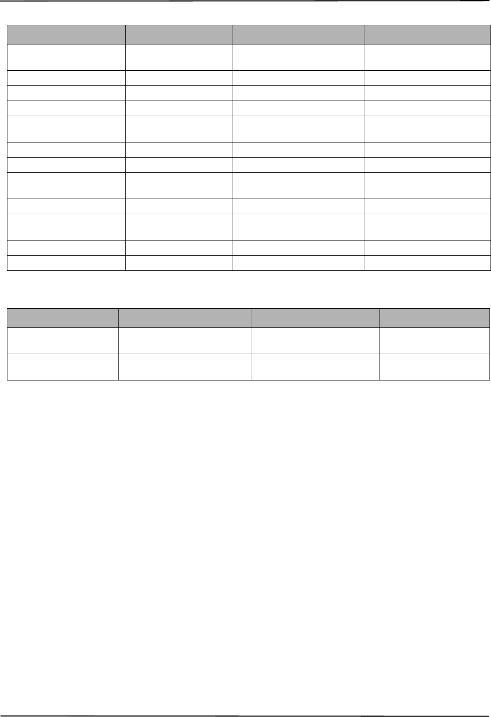
2G Alarm Communicator Installlation Manual Communicator Event Label Programming
23
COMMUNICATOR EVENT LABEL PROGRAMMING
SMS COMMAND AND CONTROL FUNCTIONS
Users can send SMS text messages from their mobile phone to the communicator cellular phone number assigned to their system. Com-
mands are only accepted from telephone numbers that have been programmed in Sections [311]-[318]. The system will reject messages
sent from telephone numbers that are not on the programmed list.
When the received SMS text matches a valid Section message, the function is performed on the control panel. Text messages are not
case sensitive and extra spaces are ignored. A User Access Code may be required for some SMS messages.
The User can send just the partition number or the complete label.(e.g., “Away arm Partition 2 1234” is treated the same as “away arm
2 1234 ”).
The SMS Message format is in 3 parts: Command, Partition Label (or only the partition number), and Access Code.
• If an Access Code is included in the message, it is sent to the control panel for validation, along with the requested function.
• If the panel is configured to require an Access Code and the code is not sent (or invalid) the panel will fail the function (unsuccess-
ful).
• If the panel fails the function, an SMS response message is sent to the user. The SMS response will echo the command sent, followed
by the label “unsuccessful”. (e.g., “night arm partition 2 1234 unsuccessful”).
• The partition label or partition number may be excluded from the SMS request in a single partition system (e.g., disarm 9123).
NOTE: The communicator cellular phone number can be viewed in Section [851], [996] and/or [851], [996] or by user entering *6,
then scrolling down to ‘SMS Programming” and scrolling down to “Cellular phone No.” [<] [>] “Cellular Phone No.” at the
keypad. An Access Code is required for all SMS commands, except Help.
[601] Stay Arm
Default (Stay Arm);
Send this command to the system to stay arm. It may be followed by a Partition Label or partition number and Access Code.
[602] Away Arm
Default (Away Arm);
Send this command to the system to away arm. It may be followed by a Partition Label or partition number and Access Code.
[603] Night Arm
Default (Night Arm);
Send this command to the system to night arm. It may be followed by a Partition Label or partition number and Access Code.
[557] General System Trouble [General System Trouble] [558] General System Trouble
Restore
[General System Trouble
Restore]
[559] AC Line Trouble [AC Power Failure] [560] AC Line Trouble Restore [AC Power Restore]
[561] Battery Trouble [Battery Trouble] [562] Battery Trouble Restore [Battery Restore]
[563] Bell Circuit Trouble [Bell Circuit Trouble] [564] Bell Circuit Trouble Restore [Bell Circuit Restore]
[565] Auxiliary Power Trou-
ble [Auxiliary Power Trouble] [566] Auxiliary Power
Trouble Restore [Auxiliary Power Restore]
[567] Ground Fault [Ground Fault Trouble] [568] Ground Fault Restore [Ground Fault Restore]
[569] TLM Failure [Telephone Line Failure] [570] TLM Failure Restore [Telephone Line Restore]
[571] FTC Trouble [Fail To Communicate
Trouble] [572] FTC Restore [Fail To Communicate Restore]
[573] Event Buffer 75% Full [Event Buffer Near Full] [574] DLS Lead In [Remote Programming Begin]
[575] DLS Lead Out [Remote Programming
End] [576] Installer Lead In [Local Programming Begin]
[577] Installer Lead Out [Local Programming End] [578] Walk Test Lead In [Walk Test Begin]
[579] Walk Test Lead Out [Walk Test End] [580] System Test [System Test Message]
Table 16: Communicator Event Label
Event Section Label Default Label Event Section Label Default Label
[591] Panel Absent Trouble [Panel Communications Trouble] [592] Panel Absent
Trouble Restore
[Panel Communications
Restored]
[593] Module
Reprogramming
[Communicator Programming
Updated] [594] Firmware Update [Communicator Firmware
Updated]
Table 15: Panel Event Labels
Event [Section] Label Default Label Event [Section] Label Default Label
29008218R001_NOVA_TL255GS_GS2055_V.2.5X_IM_ENG_NA_UL_ULC_FCC_IC_dft_03

SMS Command and Control Response 2G Alarm Communicator Installlation Manual
24
[604] Disarm
Default (Disarm);
Send this command to the system to disarm. It may be followed by a Partition Label or partition number and Access Code.
[605] - [608] Activate Command Output 1 - 4
Default (Activate Command Output n);
Where n is a number from 1 - 4. Send this command to the system to activate a command output. It may be followed by a Partition
Label or partition number and Access Code.
[609] - [612] Deactivate Command Output 1 - 4
Default (Deactivate Command Output n);
Where n is a number from 1 - 4. Send this command to the system to deactivate a command output. This command may be followed by
a Partition Label or partition number and optional Access Code.
[613] Bypass
Default (Bypass);
Send this command to the system to bypass a Zone. This command should be followed by a Zone label or Zone number and Access
Code.
[614] Unbypass
Default (Unbypass);
Send this command to the system to unbypass a Zone. This command should be followed by the Zone label or Zone number and Access
Code.
[615] Status Request
Default (Status Request);
Send this command to request the status of the system. It may be followed by a partition label or partition number and Access Code. If
partition label is omitted, status of all enabled partitions will be sent. If there is a trouble on the system, the system label is sent, fol-
lowed by the trouble label, then the partition status.
NOTE: Status Request response may require more than 1 SMS message, depending on status of the system. There is a 10 second delay
between transmission of SMS messages.
[616] Alarm Memory Request
Default (Alarm Memory Request);
Send this command to the system to request the alarm memory from the system. This command may be followed by a Partition Label or
partition number, and Access Code. If partition label is omitted, alarm memory of all partitions will be sent. Alarm memory responses
will include Partition label and Zone label. Up to 8 partitions may be contained in 1 message.
NOTE: Alarm Memory Request response may require more than 1 SMS message, depending on alarm memory of the unit. There is a
10 second delay between transmission of SMS messages.
[617] Help
Default (Help);
When help is sent, the SMS response is a listing of all Interactive commands that can be sent to the module. Access Code is not
required.
[619] Keypad Message
Default (Keypad Message);
The response format is: [Account Label] [Date and Time] [SMS Function] [Response] [Message Text]. Fields are space delim-
ited.When Keypad Message is sent, the SMS response is the message displayed on the keypad. If the message is too long to display on
the keypad, only the portion displayed is sent in the response.
SMS COMMAND AND CONTROL RESPONSE
NOTE: SMS Command and Control Response messages are up to 32 ASCII characters (Maximum 160 characters per SMS message).
The message language is specified in Section [009]. SMS responses are sent to the phone that initiated the command.
[621] Function Successful
Default (Successful);
When an SMS Command and Control function is successfully performed by the panel, the successful label is included in the response
sent to the user, following the command requested. (e.g., if “stay armed” command is completed by the panel, SMS response is: “stay
armed successful”).
[622] Function Unsuccessful
Default (Unsuccessful);
When an SMS Command and Control function is not successfully performed by the panel, the command sent to the unit will be
included in the response sent to the user, followed by this label. (e.g., if “stay armed” command is not completed, SMS response is:
“stay armed unsuccessful”).
[623] Invalid Command
Default (Invalid Command);
This label will be included in the response message if the command was not accepted as a valid SMS command.
[624] System Stay Armed
Default (Stay Armed);
This label will be included in the response to a status request command if a partition is stay armed.
[625] System Away Armed
Default (Away Armed);
This label will be included in the response to a status request command if a partition is away armed.
29008218R001_NOVA_TL255GS_GS2055_V.2.5X_IM_ENG_NA_UL_ULC_FCC_IC_dft_03
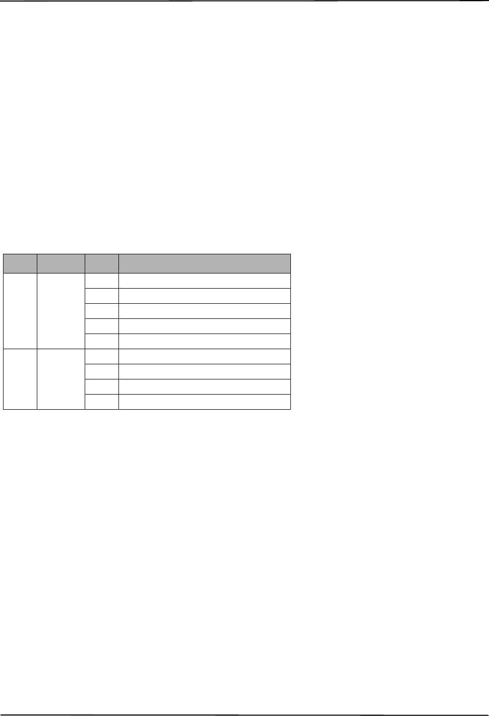
2G Alarm Communicator Installlation Manual SMS Command and Control Response
25
[626] System Night Armed
Default (Night Armed);
This label will be included in the response to a status request command if a partition is night armed.
[627] System Disarmed Ready
Default (Disarmed Ready);
This label will be included in the response to a status request command if a partition is disarmed and is ready to arm.
[628] System Disarmed Not Ready
Default (Disarmed Not Ready);
This label will be included in the response to a status request command if a partition is disarmed and is not ready to arm.
[629] System is in Alarm
Default (is in Alarm);
This label will be included in the response to a status request command if a partition is in alarm.
[630] Trouble Label
Default (Service is Required);
This label will be included in the response to the Alarm Memory command if there are no alarms in memory.
[631] No Alarms in Memory
Default (No Alarm Memory);
This label will be included in the response to an Alarm Memory Request if there are no alarms on the system.
[634] Error Code
Default (Error Code);
When an SMS initiated function fails, the module will send an error code to the telephone number that was source of the
SMS request. Message format is: [Account Label] [Date and Time] [Error Code] [Error Type]. Fields are “space” delimited.
Interactive Options
(TL255GS and GS2055 only)
[651] Interactive Account Code
Default (MAC or IMEI);
This section is programmed as 2 field by 6 hexadecimal number (12 characters). Valid range for each field is
000000 ~ FFFFFF. The IMEI can be viewed in Section [997]. The MAC address can be viewed in Section [998].
[652] Interactive Access Code
Default (12345678);
This section is programmed with the hexadecimal Interactive access code. Valid range is 0000 ~ FFFF.
[662] Interactive Port Settings Toggle
Program this section Toggles to select the Parity used for Interactive data transfers:
[1] Parity Enable05
Default (OFF)
ON: Parity is enabled.
OFF: Parity is disabled.
[2] Parity Type
Default (OFF)
ON: Even Parity is enabled.
OFF: Odd Parity is enabled.
[3] Stop Bits
Default (OFF)
ON: One Stop bit is used.
OFF: Two Stop bits are used.
[4] Flow Control
Default (OFF)
ON: Flow Control is enabled.
Table 17: Error Code Format
Class Definition Error Definition
01 DLS
01 Bad SMS format
02 Session failed due to local network issues
03 Unable to connect to remote server
04 Bad DLS access code
05 DLS lockout active
02 TFTP
01 Bad SMS format
02 Session failed due to local network issues
03 Unable to connect to remote server
04 File not found on TFTP server
29008218R001_NOVA_TL255GS_GS2055_V.2.5X_IM_ENG_NA_UL_ULC_FCC_IC_dft_03
SMS Command and Control Response 2G Alarm Communicator Installlation Manual
26
OFF: Flow Control is disabled.
[5]-[8]Reserved
Default (OFF)
[663] Interactive Feature Toggle Option
This feature is used to select the interactive feature services.
Bit [1] Reserved. {Interactive over serial port (default Enabled) - on -SM manual}
Bit [2] Interactive over cellular radio (default Disabled)
Bit [3] Future use
Bit [4] Default (ON)
ON: Interactive over Cellular radio is Primary.
OFF: Reserved
Bit [5] Future use
Bit [6] Future use
Bit [7] Future use
Bit [8] Interactive Encryption
Default (ON)
[671] Life-Style Event Toggle
This section determines the events recorded in the Life-Style Log. When the Life-Style buffer is 75% full, the Communicator will connect to the iControl
Server through the iHub and upload the Life-Style information. The log can buffer 1,000 Life-Style events.
NOTE: No FTC trouble Life-Style shall be generated for Life-Style Events.
[1] Life-style Log Alarm/Restore
Default (ON)
[2] Life-style Log Tamper/Restore
Default (ON)
[3] Life-style Log Opening/Closing
Default (ON)
[4] Life-style Log System Maintenance
Default (ON)
[5] Life-style Log System Test
Default (ON)
[6] Life-style Log Communicator Events
Default (ON)
[7]-[8] Reserved
Default (ON)
[672] Life-Style Zone 1 - 8 Toggle Options
The default for each Life-Style Zone Toggle is ON.
[673] Life-Style Zone 9 - 16 Toggle Options
The default for each Life-Style Zone Toggle is ON.
[674] Life-Style Zone 17 - 24 Toggle Options
The default for each Life-Style Zone Toggle is ON.
[675] Life-Style Zone 25 - 32 Toggle Options
The default for each Life-Style Zone Toggle is ON.
Table 18: Life-Style Zone 1 - 8 Toggle
TOGGLE 01 02 03 04 05 06 07 08
ZONE 12345678
Table 19: Life-Style Zone 9 - 16 Toggle
TOGGLE 01 02 03 04 05 06 07 08
ZONE 9 10111213141516
Table 20: Life-Style Zone 17 - 24 Toggle
TOGGLE 01 02 03 04 05 06 07 08
ZONE 17 18 19 20 21 22 23 24
Table 21: Life-Style Zone 25 - 32 Toggle
TOGGLE 01 02 03 04 05 06 07 08
ZONE 25 26 27 28 29 30 31 32
29008218R001_NOVA_TL255GS_GS2055_V.2.5X_IM_ENG_NA_UL_ULC_FCC_IC_dft_03
2G Alarm Communicator Installlation Manual SMS Command and Control Response
27
[676] Life-Style Zone 33 - 40 Toggle Options
The default for each Life-Style Zone Toggle is ON.
[677] Life-Style Zone 41 - 48 Toggle Options
The default for each Life-Style Zone Toggle is ON.
[678] Life-Style Zone 49 - 56 Toggle Options
The default for each Life-Style Zone Toggle is ON.
[679] Life-Style Zone 57 - 64 Toggle Options
The default for each Life-Style Zone Toggle is ON.
[681] Notification Event Toggle
This section determines the Notification events that are reported. Default for all is OFF.
[1] Life-style Log Alarm/Restore
Default (OFF)
[2] Life-style Log Tamper/Restore
Default (OFF)
[3] Life-style Log Opening/Closing
Default (OFF)
[4] Life-style Log System Maintenance
Default (OFF)
[5] Life-style Log System Test
Default (OFF)
[6] Life-style Log Communicator Events
Default (OFF)
[7]-[8] Reserved
Default (OFF)
[682] Notification Zone 1 - 8 Toggle Options
The default for each Notification Zone Toggle is OFF.
[683] Notification Zone 9 - 16 Toggle Options
The default for each Notification Zone Toggle is OFF.
[684] Notification Zone 17 - 24 Toggle Options
The default for each Notification Zone Toggle is OFF.
Table 22: Life-Style Zone 33 - 40 Toggle
TOGGLE 01 02 03 04 05 06 07 08
ZONE 33 34 35 36 37 38 39 40
Table 23: Life-Style Zone 41 - 48 Toggle
TOGGLE 01 02 03 04 05 06 07 08
ZONE 41 42 43 44 45 46 47 48
Table 24: Life-Style Zone 49 - 56 Toggle Options
TOGGLE 01 02 03 04 05 06 07 08
ZONE 49 50 51 52 53 54 55 56
Table 25: Life-Style Zone 57 - 64 Toggle Options
TOGGLE 01 02 03 04 05 06 07 08
ZONE 57 58 59 60 61 62 63 64
Table 26: Notification Zone 1 - 8 Toggle
TOGGLE 01 02 03 04 05 06 07 08
ZONE 12345678
Table 27: Notification Zone 9 - 16 Toggle
TOGGLE 01 02 03 04 05 06 07 08
ZONE 9 10111213141516
Table 28: Notification Zone 17 - 24 Toggle
TOGGLE 01 02 03 04 05 06 07 08
ZONE 17 18 19 20 21 22 23 24
29008218R001_NOVA_TL255GS_GS2055_V.2.5X_IM_ENG_NA_UL_ULC_FCC_IC_dft_03
SMS Command and Control Response 2G Alarm Communicator Installlation Manual
28
[685] Notification Zone 25 - 32 Toggle Options
The default for each Notification Zone Toggle is OFF.
[686] Notification Zone 33 - 40 Toggle Options
The default for each Notification Zone Toggle is OFF.
[687] Notification Zone 41 - 48 Toggle Options
The default for each Notification Zone Toggle is OFF.
[688] Notification Zone 49 - 56 Toggle Options
The default for each Notification Zone Toggle is OFF.
[689] Notification Zone 57 - 64 Toggle Options
The default for each Notification Zone Toggle is OFF.
[691] Interactive Over data Server 1 account code
Default (0000000000)
The account code is used by interactive server to distinguish between different transmitters.
[692] Interactive Over data Server 1 DNIS
Default (0000000000)
The DNIS is used in addition to the account to identify the communicator module at the interactive server.
[693] Interactive Over 2G server 1 IP address
Default (000.000.000.000)
Enter the interactive over data server 1 IP address. This information will be provided by your interactive server administrator. Each 3
digit segment of the address must be within the valid range of 000-255.
NOTE: When a valid IP address has been entered, the interactive server is enabled and will communicate events over the data channel.
[694] Interactive over 2G server 1 TCP port
Default ( )
This Section determines the TCP port used by interactive server 1 for control response. Change the default value of this port when your
installation is located behind a firewall, and must be assigned a particular port number as determined by your central station system
administrator.
Valid range: 0000 - FFFF
[695] Interactive over 2G server 1 UDP port
Default ( )
This Section determines the UDP port used by interactive server 1 t events communication. Change the default value of this port when
your installation is located behind a firewall, and must be assigned a particular port number as determined by your central station sys-
tem administrator.
Valid range: 0000 - FFFF.
[696] Interactive over 2G server 1 APN
Default ( )
The Access Point Name (APN) determines the interactive server network that the Communicator will connect to. This information is
available from your network carrier. Program this Section as 32 ASCII characters.
NOTE: The Server 1 APN should be same as the receiver 1 APN in section [205].
[697] Interactive over 2G server 1 Domain name
Default ( )
Table 29: Notification Zone 25 - 32 Toggle
TOGGLE 01 02 03 04 05 06 07 08
ZONE 25 26 27 28 29 30 31 32
Table 30: Notification Zone 33 - 40 Toggle
TOGGLE 01 02 03 04 05 06 07 08
ZONE 33 34 35 36 37 38 39 40
Table 31: Notification Zone 41 - 48 Toggle
TOGGLE 01 02 03 04 05 06 07 08
ZONE 41 42 43 44 45 46 47 48
Table 32: Notification Zone 49 - 56 Toggle
TOGGLE 01 02 03 04 05 06 07 08
ZONE 49 50 51 52 53 54 55 56
Table 33: Notification Zone 57 - 64 Toggle
TOGGLE 01 02 03 04 05 06 07 08
ZONE 57 58 59 60 61 62 63 64
29008218R001_NOVA_TL255GS_GS2055_V.2.5X_IM_ENG_NA_UL_ULC_FCC_IC_dft_03

2G Alarm Communicator Installlation Manual SMS Command and Control Response
29
Enter the Domain Name as 32 ASCII characters. This information will be provided by your central station system administrator.
[698] Interactive over 2G local event report port (UDP Port)
Default (3076)
This Section is used to program the DUP port number used the communicator.
[699] Interactive over 2G local control response port (TCP Port)
Default (3071)
This Section is used to program the TCP port number used by the communicator.
[701] Interactive Over 2G Server 2 account code
Default (0000000000)
The account code is used by interactive server to distinguish between different transmitters.
[702] Interactive Over 2G Server 2 DNIS
Default (0000000000)
The DNIS is used in addition to the account to identify the communicator module at the interactive server.
[703] Interactive Over 2G server 2 IP address
Default (000.000.000.000)
Enter the interactive over data server 2 IP address. This information will be provided by your interactive server administrator. Each 3
digit segment of the address must be within the valid range of 000-255.
NOTE: When a valid IP address has been entered, the interactive server is enabled and will communicate events over the data channel.
[704] Interactive Over 2G Server 2 TCP port
Default ( )
This Section determines the TCP port used by interactive server 1 for control response. Change the default value of this port when your
installation is located behind a firewall, and must be assigned a particular port number as determined by your central station system
administrator.
Valid range: 0000 - FFFF
[705] Interactive over 2G server 2 UDP port
Default ( )
This Section determines the UDP port used by interactive server 1 t events communication. Change the default value of this port when
your installation is located behind a firewall, and must be assigned a particular port number as determined by your central station sys-
tem administrator.
Valid range: 0000 - FFFF
[706] Interactive over 2G server 2 APN
Default ( )
The Access Point Name (APN) determines the interactive server network that the Communicator will connect to. This information is
available from your network carrier. Program this Section as 32 ASCII characters.
NOTE: The Server 1 APN should be same as the receiver 1 APN in section [215]
[707] Interactive Over data Server 2 Domain name
Default ( )
Enter the Domain Name as 32 ASCII characters. This information will be provided by your central station system administrator.
[708] Event report retry interval
Default (0102040810101010)
This section is used to program the event transmission to interactive server retry time interval. The interval time given in seconds.
(The default reties are after 1 second, 2 second, 4 second, 8 second and 10 seconds x4)
[709] Event report retries timeout
Default (300)
This section is used to program the time to try communicating the event before giving up the event transmission. The time is given in
seconds.
[710] Event buffer upload timeout
Default (86400)
This section is used to program the time before discarding the event buffer content. The time is given in seconds.
[711] TCP connection time out
Default (1200)
This section is used to program the time to keep the TCP connection open for control response.
29008218R001_NOVA_TL255GS_GS2055_V.2.5X_IM_ENG_NA_UL_ULC_FCC_IC_dft_03

System Information (Read Only) 2G Alarm Communicator Installlation Manual
30
RECEIVER DIAGNOSTIC TESTING
[901] Diagnostic Test Transmission
[1] Ethernet 1 (OFF).
[2] Ethernet 2 (OFF).
[3] Cellular 1 (OFF).
[4] Cellular 2 (OFF).
[5],[6],[7],[8] Reserved (OFF).
This Section may be used by the installer to force the Communicator to send an immediate test transmission to specific receivers, to
verify that the communications paths are available. Diagnostic Test Transmission failure will indicate as FTC trouble (Yellow LED = 9
flashes). If an FTC error occurs when testing all receivers, select only one receiver and repeat test to isolate the receiver that is not com-
municating.
SYSTEM INFORMATION (READ ONLY)
NOTE: Sections [987] - [998] are provided for information (Read Only). Values in these Sections can not be modified by the Installer.
[987] Language Version
This Section will display the current Language version of the Communicator.
[988] DNS 1 IP Address
This Section will display the IP address of DNS Server 1. This is useful when the unit is configured for DHCP and you need to see the
IP address was assigned to the device by the DHCP Server. This value is programmed in Section [007] or assigned by DHCP.
[989] DNS 2 IP Address
This Section will display the IP address of DNS Server 2. This is useful when the unit is configured for DHCP and you need to see the
IP address that was assigned to the device by the DHCP Server. This value is programmed in Section [008] or assigned by DHCP.
[990] Boot Loader Version
This Section will display the current Boot Loader version of the Communicator.
[991] Firmware Version
This Section will display the current firmware version of the device. Update worksheets with new version after a flash update is com-
pleted.
[992] Ethernet IP Address
This Section will display the IP address of the Ethernet connection. This value is programmed in Section [001] or assigned by DHCP.
[993] Ethernet Gateway Address
This Section will display the IP address of the Ethernet Gateway. This value is programmed in Section [003] or assigned by DHCP.
[994] Cellular IP Address
This Section will display the current dynamic IP address assigned by DHCP to the Cellular connection.
NOTE: Cellular uses DHCP (Dynamic IP) only. The Cellular IP address is always provided by the Cellular network (i.e., not program-
mable).
[995] SIM Number
This Section will display the Subscriber Identity Module (SIM) number of the SIM card installed in the Communicator. Format is:
Major Industry Identifier (2 digits) Mobile Country Code (2 or 3 digits); Mobile Network Code (2 - 3 digits); Unique Number (10 - 12
digits); and Checksum (1 digit). Valid SIM numbers range is: 18 - 21 numbers. This number is printed on SIM and the outside of the
Communicator carton.
NOTE: The Checksum digit is omitted on 19 digit SIM Card numbers.
[996] Cellular Telephone Number
NOTE: This Section will display the Cellular telephone number of the SIM. This telephone number is required by the Installer for DLS
and remote firmware (flash) update. User can access this telephone number by entering [*] [6] < > “Cellular Phone No.” to dis-
play the phone number.
[997] IMEI Number
This Section will display the unique 15 digit International Mobile Equipment Identity (IMEI) of the radio. Format is: Reporting Body
Identifier (2 digits), Allocation Number (4 digits); Final Assembly Code (2 digits); Serial Number (6 digits); and a check digit.
[998] MAC Address
This Section will display the unique12 digit, hexadecimal number assigned as the Media Access Control (MAC) address of the device.
SYSTEM RESET DEFAULTS
[999] Software Default
Default (99);
The Software default allows the installer to refresh the unit after changes and also return the Communicator to the default state.
00: Default Module. All programming Sections in module revert to factory settings. This will erase all existing programming of the
unit.
55: Reset. The Communicator is reset. This option is equivalent to power cycling the Communicator.
29008218R001_NOVA_TL255GS_GS2055_V.2.5X_IM_ENG_NA_UL_ULC_FCC_IC_dft_03
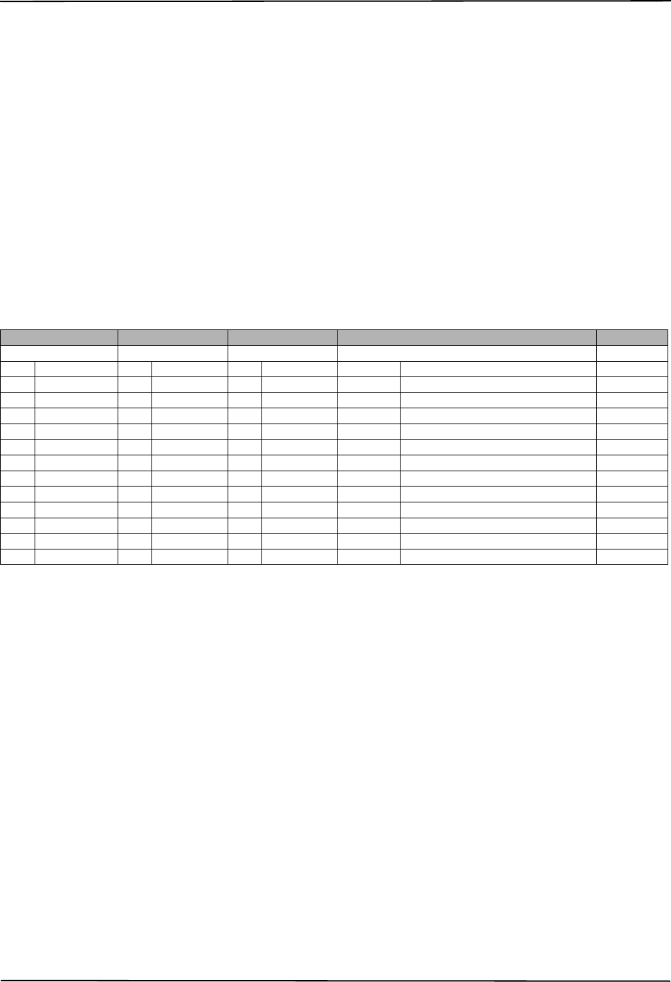
2G Alarm Communicator Installlation Manual Communicator Troubleshooting
31
Communicator Troubleshooting
[984] Communicator Status
The communicator status sections are intended to provide the installer with real time status of communicator’s functionality, opera-
tional readiness, failures, and potential malfunctions that may affect flawless operation of the communicator and its primary function of
sending signal to the central station in case the monitored event occurs.
The communicator status is displayed in the form of 6 digits CODE (6 hexadecimal numbers) as in the following pattern: 00000F. The
range of the all possible codes stretches from: 00000F – 22206F. Not all numbers in this range are assigned status code. (Some numbers
are skipped, i.e. not assigned the code.)
Each digit displays the status of assigned function on (or trouble with) communicator as following:
1.
Digit 1 - Signal Indicator 1, displays the presence/strength of signal 1;
2. Digit 2 - Signal Indicator 2, displays the presence/strength of signal 2;
3. Digit 3 - Network Indicator, displays the presence (operational status) of network;
4. Digit 4 & 5 – TROUBLE INDICATOR displays the type of problem/malfunction on communicator or modules associated with and
connected to communicator.
5. Digit 6 – Reserved for future use.
For example status code 11103F – when interpreted means: “Signal Indicator 1 OK, Signal indicator 2 OK, Network is working,
POWER SUPPLY TROUBLE.” For details see the table below:
Table 34: Communicator Status and Trouble Coding - Hexadecimal Codes & Corresponding LED Equivalents
The communicator status codes will emulate corresponding LED status as indicated in table above. For example status code 11103F
would display following LED stats:
1 – LED On = Signal indicator 1, signal is OK (Green 1 LED)
1 – LED On = Signal indicator 2, signal is OK (Green 2 LED)
1 – LED On = Network indicator, network is working (Yellow LED)
03 – TROUBLE INDICATOR = Power supply trouble. (Red LED)
F – Future code not assigned yet. It is sixth hexadecimal digit. It could be also ‘ - ‘ (dash) instead of letter F (11103-).
[985] Radio Initialization Status
The radio initialization status is intended to provide the installer with real time status of radio communication. The radio initialization
status is displayed in 8 bit toggle option. Each digit indicates one task in radio initialization process that is complete step in entire pro-
cess of radio initialization as following:
1. Radio power up
2. Receiving the SMS from C24
3. Radio reset
4. Radio attached to network
5. Receiver 1 Initialized
6. Receiver 2 Initialized
7. Receiver 3 Initialized
8. Receiver 4 Initialize
The he following table shows each digits position in status code and each digit’s value and its assigned meaning in the eight digits code:
Digit 1 Digit 2 Digit 3 Digit 4 & 5 Digit 6
Signal indicator 1 Signal indicator 2 Network indicator TROUBLE INDICATOR Future use
0 LED Off 0 LED Off 0 LED Off 00 LED Off ( No trouble) F
1 LED On 1 LED On 1 LED On 01 Battery Trouble F
2 LED Flashing 2 LED Flashing 2 LED Flashing 02 LED Flashing F
03 Power supply trouble F
04 Lockout trouble F
05 2G/Cellular trouble F
06 Ethernet Trouble F
07 Receiver Not Available F
08 Receiver Supervision F
09 FTC Trouble F
0A C24 Configuration SMS Failure F
0B Remote Programming F
0C Module configuration Trouble F
29008218R001_NOVA_TL255GS_GS2055_V.2.5X_IM_ENG_NA_UL_ULC_FCC_IC_dft_03

Communicator Troubleshooting 2G Alarm Communicator Installlation Manual
32
For example the radio initialization status code 12345--- indicates that Radio has been powered up, it has received SMS signal from C24, the radio has
been reset, the radio is attached to the network, and Radio 1 has been initialized. This code could be followed with...567 if Receivers 2, 3, and 4 are ini-
tialized where applicable.
If the radio initialization status code does not indicate any problems proceed with installation as per this manual. If troubles are reported reset the initial-
ization process. If this action does not fix the problem refer to Trouble shooting section in this manual.
Table 36: Trouble Code Indications
Table 35: Radio Initialization Status - 1-8 bits completion
Bit 12345678
Not Completed --------
Completed 12345678
Trouble Indicator
Digit Possible Causes Trouble Possible Solutions
00 No Trouble N/A
01 Battery Trouble Verify batteries voltage. Replace dead batteries.
Check batteries connections: make sure connection are snug and clean. Clean batteries connects
and reinstall batteries.
02 Panel Supervision Trou-
ble
Check Section [382]Toggle Option[5] is ON.(GPRS/Ethernet Module Enabled)
Ensure the PC-LINK cable between the Panel and Communicator is connected properly (not
reversed) and is securely in place.
03 Power Supply Trouble Perform troubleshooting process as for the Code 00.
04 Lockout Trouble The SIM card has incorrect PIN programmed or has a PIN that the module does not recognize.
Replace the SIM card.
05 2G/Cellular Trouble
Confirm that GPRS service is available and active in your area.
Check all antenna connections.
Ensure average radio signal strength is CSQ 6 or higher. (See Table 4 ).
Ensure the SIM card is properly inserted into the SIM card holder.
Ensure the SIM card has been activated. (Could take up to 24 hrs after install).
If this trouble persists, you must relocate the Panel (and Communicator) or install an external
antenna extension kit.
06 Ethernet Trouble
Check with your ISP to confirm Internet service is active in your area.
Ensure your Ethernet cable is securely inserted into the RJ45 jack of the Communicator and the
Hub/Router/ Switch.
Check the link light on the Hub/Router/ Switch is ON . If link light is OFF, try restarting the
Hub/Router/ Switch.
If DHCP is used, ensure that the unit has an assigned IP address from the server.
In Section [851] [992] verify a valid IP address is programmed. If not, contact the Network
administrator.
If problem persists, replace the Ethernet cable and RJ45 connector.
07 Receiver Not Available
Ensure that the Ethernet path has internet connectivity.
If you are using a static IP address make sure the gateway and subnet mask are entered correctly.
If the network has a firewall, ensure the network has the programmed outgoing ports open
(Default UDP Port 3060 and Port 3065).
Ensure that all the receivers are programmed for DHCP or have the proper IP address and port
number.
Ensure the GPRS Receiver APNs have been programmed with the Access Point Name provided
by your GPRS provider.
08 Receiver Supervision
Trouble
This trouble is indicated when supervision is enabled and the unit is not able to successfully
communicate with the receiver.
If this trouble persists, contact your central station.
09 FTC Trouble The unit has exhausted all communications attempts to all programmed receiver for events gen-
erated by the Communicator.
Restart the system, if trouble persists, contact your dealer.
0A Connect24 Configura-
tion Failure
The SIM is active but there is no programming for the Communicator.
Ensure a profile has been programmed in Connect 24 for the SIM.
You can confirm your programming by calling the Connect 24 VRU, or by logging into the
Connect24 VRU web site.
0B Remote Programming
The LEDs will flash when a remote firmware upgrade is in progress over Ethernet or GPRS. The
LEDs will extinguish when update is complete.
The LEDs will flash to indicate a remote programming session is active over Ethernet or GPRS.
The LEDs will extinguish when the session terminates.
0C Module Configuration
Trouble
This indication appears when Section [021] System Account Code or Section [101]; [111];
[201]; and [211] Receiver Account Code have not been programmed. Ensure that a valid
account code has been entered in these Sections.
29008218R001_NOVA_TL255GS_GS2055_V.2.5X_IM_ENG_NA_UL_ULC_FCC_IC_dft_03

2G Alarm Communicator Installlation Manual Communicator Troubleshooting
33
Communicator Troubleshooting
The status code for the radio signal strength, its typical troubles, possible causes and troubleshooting instructions is displayed in the table below.
Table 37: Radio Signal Strength
Signal
Strength CSQ Level Yellow LED Green LED2 Green LED1 Signal Level
[dBm] Action Required
No Signal 0 ON OFF OFF -108.8 Check all antenna connections.
Confirm GPRS service is active in area.
Relocate Panel or install external antenna.
1 Bar 1 - 4 ON OFF Flashing -108 ~ -103 Relocate Panel or install external antenna if Yel-
low Trouble LED has:
5 flashes.
2 Bars 5 - 6 OFF
See Note OFF Flashing -102 ~ -99
3 Bars 7 - 10 OFF OFF ON -98 ~ -91
Location is OK. GPRS Signal Strength is
greater than CSQ 5.
4 Bars 11 - 13 OFF Flashing ON -90 ~ -85
5 Bars 14 + OFF ON ON -84 and
higher
29008218R001_NOVA_TL255GS_GS2055_V.2.5X_IM_ENG_NA_UL_ULC_FCC_IC_dft_03

System Options 2G Alarm Communicator Installlation Manual
34
SYSTEM OPTIONS
[001] Ethernet IP Address
Default (000.000.000.000)
|____|____|____||____|____|____||____|____|____|____|____|____|
[002] Ethernet IP Subnet Mask
Default (255.255.255.000)
|____|____|____||____|____|____||____|____|____|____|____|____|
[003] Ethernet Gateway IP Address
Default (000.000.000.000)
|____|____|____||____|____|____||____|____|____|____|____|____|
[004] Receiver Supervision Interval
Default (0087/135) Valid range: 0000 - FFFF.
|____|____|____|____|
[005] System Toggle Options
|____| [1] Ethernet Receiver 1 Supervised Default (OFF).
|____| [2] Cellular Receiver 1 Supervised Default (OFF).
|____| [3] Supervision Type Default (OFF).
|____| [4] Primary Communications Path.
Default [OFF] TL255GS; [ON]GS2055.
|____| [5] Redundant Communications Default (OFF).
|____| [6] Remote Firmware Upgrade Default (ON).
|____| [7] Alternate Test Transmission Default (OFF).
|____| [8] Cellular Low Signal Trouble Default (OFF).
[006] System Toggle Options 2
|____| [1] Ethernet Receiver 1 Enabled Default (ON).
|____| [2] Ethernet Receiver 2 Enabled Default (ON).
|____| [4] Cellular Receiver 1 Enabled Default (ON).
|____| [5] Cellular Receiver 2 Enabled Default (ON).
|____| [7] DLS Over Cellular Default (ON).
|____| [8] Interactive Over Cellular Default (ON).
[007] DNS Server IP 1
Programming not permitted on UL/ULC listed system.
Default (000.000.000.000)
|____|____|____||____|____|____||____|____|____|____|____|____|
[008] DNS Server IP 2
Programming not permitted on UL/ULC listed system.
Default (000.000.000.000)
|____|____|____||____|____|____||____|____|____|____|____|____|
PROGRAMMING OPTIONS
[010] System Toggle Option
Default (CAFE) Valid range: 0000 - FFFF.
|____|____|____|____|
[011] Installer Code
Default (CAFE) Valid range: 0000 - FFFF.
|____|____|____|____|
[012] DLS Incoming Port
Default (0BF6/3062) Valid range: 0000 - FFFF.
|____|____|____|____|
[013] DLS Outgoing Port
Default (0BFA/3066) Valid range: 0000 - FFFF.
|____|____|____|____|
[020] Time Zone
Default (CAFE) Valid range: 0000 - FFFF.
|____|____|____|____|
[022] Communications Format
Default (04) Program 03 (CID), 04 (SIA).
|____|____|
[023] Panel Absent Trouble
Default (FF); Program 00 disable or FF enable.
|____|____|
[024] Panel Absent Trouble Restore
Default (FF) Program 00 disable or FF enable.
|____|____|
[025] Radio Activation Restore
Default (FF) Program 00 disable or FF enable.
|____|____|
SYSTEM TEST OPTIONS [026 - 029]
[026] Ethernet 1 Transmission
Default (FF) Program 00 disable or FF enable.
|____|____|
[027] Ethernet 2 Transmission
Default (00) Program 00 disable or FF enable.
|____|____|
[028] Cellular 1 Transmission
Default (FF) Program 00 disable or FF enable.
|____|____|
[029] Cellular 2 Transmission
Default (00) Program 00 disable or FF enable.
|____|____|
[030] FTC Restore
Default (FF) Program 00 disable or FF enable.
|____|____|
ETHERNET RECEIVER 1 OPTIONS
[101] Ethernet Receiver 1 Account Code
Default (0000000000)
Valid range: 0000000001 - FFFFFFFFFE.
|____|____|____|____|____|____|____|____|____|____|
[102] Ethernet Receiver 1 DNIS
Default (000000) Valid range: 000000 - FFFFFF.
|____|____|____|____|____|____|
[103] Ethernet Receiver 1 Address
Default (127.000.000.001)
|____|____|____||____|____|____||____|____|____|____|____|____|
[104] Ethernet Receiver 1 Remote Port
Default (0BF5/3061) Valid range: 0000 - FFFF.
|____|____|____|____|
[105] Ethernet Receiver 1 Local Port
Default (0BF4/3060)Valid range: 0000 - FFFF.
|____|____|____|____|
[106] Ethernet Receiver 1 Domain Name
Default ( ) 32 ASCII characters.
Programming not permitted on UL/ULC listed system.
________________________________
ETHERNET/CELLULAR PROGRAMMING WORKSHEETS
29008218R001_NOVA_TL255GS_GS2055_V.2.5X_IM_ENG_NA_UL_ULC_FCC_IC_dft_03

2G Alarm Communicator Installlation Manual Ethernet Receiver 2 Options
35
ETHERNET RECEIVER 2 OPTIONS
[111] Ethernet Receiver 2 Account Code
Default (0000000000)
Valid range: 0000000001 - FFFFFFFFFE.
|____|____|____|____|____|____|____|____|____|____|
[112] Ethernet Receiver 2 DNIS
Default (000000) Valid range: 000000 - 0FFFFF.
|____|____|____|____|____|____|
[113] Ethernet Receiver 2 Address
Default (000.000.000.000)
|____|____|____||____|____|____||____|____|____|____|____|____|
[114] Ethernet Receiver 2 Remote Port
Default (0BF5/3061) Valid range: 0000 - FFFF.
|____|____|____|____|
[115] Ethernet Receiver 2 Local Port
Default (0BF9/3065) Valid range: 0000 -FFFF.
|____|____|____|____|
[116] Ethernet Receiver 2 Domain Name
Default ( )
Programming not permitted on UL/ULC listed system.
____________________________________
ETHERNET OPTIONS
[124] Ethernet Test Transmission Time
Default (9999) Valid: 00-23(HH); 00-59(MM)
|____|____|____|____|
[125] Ethernet Test Transmission Cycle
Default (000000)
Valid range: 000000 - 999999 minutes.
|____|____|____|____|____|____|
CELLULAR RECEIVER 1 OPTIONS
[201] Cellular Receiver 1 Account Code
Default (0000000000)
Valid range: 0000000001 - FFFFFFFFFE.
|____|____|____|____|____|____|____|____|____|____|
[202] Cellular Receiver 1 DNIS
Default (000000) Valid range: 000000 - 0FFFFF.
|____|____|____|____|____|____|
[203] Cellular Receiver 1 Address
Default (000.000.000.000). Valid range: 000-255.
|____|____|____||____|____|____||____|____|____|____|____|____|
[204] Cellular Receiver 1 Port
Default (0BF5/3061) Valid range: 0000 - FFFF.
|____|____|____|____|
[205] Cellular Receiver 1 APN Default ( )
32 ASCII characters.
____________________________________
[206] Cellular Receiver 1 Domain Name
Default ( )
Programming not permitted on UL/ULC listed system.
32 Character ASCII characters.
____________________________________
CELLULAR RECEIVER 2 OPTIONS
[211] Cellular Receiver 2 Account Code
Default (0000000000)
Valid range: 0000000001 - FFFFFFFFFE.
|____|____|____|____|____|____|____|____|____|____|
[212] Cellular Receiver 2 DNIS
Default (000000)
Valid range: 000000 - 0FFFFF.
|____|____|____|____|____|____|
[213] Cellular Receiver 2 Address
Default (000.000.000.000)
Valid segment range: 000-255
|____|____|____||____|____|____||____|____|____|____|____|____|
[214] Cellular Receiver 2 Port
Default (0BF5/3061) Valid range: 0000 - FFFF.
|____|____|____|____|
[215] Cellular Receiver 2 APN
Default ( ) 32 ASCII characters.
____________________________________
[216] Cellular Receiver 2 Domain Name
Default ( )
Programming not permitted on UL/ULC listed system.
32 ASCII characters.
____________________________________
CELLULAR OPTIONS
[221] Cellular Public Access Point Name
Default ( ) 32 ASCII characters
____________________________________
[222] Cellular Login User Name
Default ( ) 32 ASCII characters.
____________________________________
[223] Cellular Login Password
Default ( ) 32 ASCII characters.
____________________________________
[224] Cellular Test Transmission Time of Day
Default (9999) Valid range: 00 - 23 hrs. (HH) 00 - 59 min. (MM).
|____|____|____|____
[225] Cellular Test Transmission Cycle
Default (000000)
Valid range: 000000 - 999999 minutes.
|____|____|____|____|____|____|
[226] Cellular Trouble Delay
Default (00)
Program 00 disable or FF enable.
|____|____|
[634] ERROR CODE
[651] Interactive Account Code
Default (MAC or IMEI)
|____|____|____|____|____|____| |____|____|____|____|____|____|
[652] Interactive Access Code
Default (1234)
|____|____|____|____||____|____|____|____|
[662] Interactive Port Settings Toggle
|____| [1] Parity Enabled Default (OFF).
|____| [2] Even/Odd Parity Default (OFF).
|____| [3]1 or 2 Stop Bits Default (OFF).
|____| [4] Flow Control. Default (OFF).
[663] Interactive Feature Toggle Option
|____| [1] Reserved
29008218R001_NOVA_TL255GS_GS2055_V.2.5X_IM_ENG_NA_UL_ULC_FCC_IC_dft_03

[634] Error Code 2G Alarm Communicator Installlation Manual
36
|____| [2] Interactive over cellular radio. Defeault (OFF)
|____| [3] Future
|____| [4] Interactive over Cellular radio is Primary Default (ON).
|____| [5] Future
|____| [6] Future
|____| [7] Future
|____| [8] Interactive Encryption Default (ON).
[671] Life-Style Event Toggle
|____|____|____|____|____|____|____|____|
1 2 3 4 5 6 7 8
[672] Life-Style Zone 1 - 8 Toggle Options
|____|____|____|____|____|____|____|____|
1 2 3 4 5 6 7 8
[673] Life-Style Zone 9 - 16 Toggle Options
|____|____|____|____|____|____|____|____|
9 10 11 12 13 14 15 16
[674] Life-Style Zone 17 - 24 Toggle Options
|____|____|____|____|____|____|____|____|
17 18 19 20 21 22 23 24
[675] Life-Style Zone 25 - 32 Toggle Options
|____|____|____|____|____|____|____|____|
25 26 27 28 29 30 31 32
[676] Life-Style Zone 33 - 40 Toggle Options
|____|____|____|____|____|____|____|____|
33 34 35 36 37 38 39 40
[677] Life-Style Zone 41 - 48 Toggle Options
|____|____|____|____|____|____|____|____|
41 42 43 44 45 46 47 48
[678] Life-Style Zone 49 - 56 Toggle Options
|____|____|____|____|____|____|____|____|
49 50 51 52 53 54 55 56
[679] Life-Style Zone 57 - 64 Toggle Options
|____|____|____|____|____|____|____|____|
57 58 59 60 61 62 63 64
[681] Notification Event Toggle
|____| [1] Alarm/Restore Default (OFF).
|____| [2] Tamper/Restore Default (OFF).
|____| [3] Opening/Closing Default (OFF).
|____| [4] System Maintenance. Default (OFF).
|____| [5] System Test Default (OFF).
|____| [6] Internal Events Default (OFF).
[682] Notification Zone 1 - 8 Toggle Options
|____|____|____|____|____|____|____|____|
1 2 3 4 5 6 7 8
[683] Notification Zone 9 - 16 Toggle Options
|____|____|____|____|____|____|____|____|
9 10 11 12 13 14 15 16
[684] Notification Zone 17 - 24 Toggle Options
|____|____|____|____|____|____|____|____|
17 18 19 20 21 22 23 24
[685] Notification Zone 25 - 32 Toggle Options
|____|____|____|____|____|____|____|____|
25 26 27 28 29 30 31 32
[686] Notification Zone 33 - 40 Toggle Options
|____|____|____|____|____|____|____|____|
33 34 35 36 37 38 39 40
[687] Notification Zone 41 - 48 Toggle Options
|____|____|____|____|____|____|____|____|
41 42 43 44 45 46 47 48
[688] Notification Zone 49 - 56 Toggle Options
|____|____|____|____|____|____|____|____|
49 50 51 52 53 54 55 56
[689] Notification Zone 57 - 64 Toggle Options
|____|____|____|____|____|____|____|____|
57 58 59 60 61 62 63 64
[689] Notification Zone 57 - 64 Toggle Options
|____|____|____|____|____|____|____|____|
57 58 59 60 61 62 63 64
[693] Interactive Over 2G server 1 IP address
Default (000.000.000.000)
|
|____|____|____| |____|____|____| |____|____|____| |____|____|____|
[694] Interactive over 2G server 1 TCP port
Default ( )
|
|____|____|____| |____|____|____| |____|____|____| |____|____|____|
[695] Interactive over 2G server 1 UDP port
Default ( )
|
|____|____|____| |____|____|____| |____|____|____| |____|____|____|
[697] Interactive over 2G server 1 Domain name
Default ( )
Enter domain name as:
32 Character ASCII characters.
____________________________________
[698] Interactive over 2G local event report port (UDP Port)
Default (3076)
____________________________________
[699] Interactive over 2G local control response port (TCP
Port)
Default (3071)
____________________________________
[701] Interactive Over 2G Server 2 account code
Default (0000000000)
|
|____|____|____| |____|____|____| |____|____|____| |____|____|____|
[702] Interactive Over 2G Server 2 DNIS
Default (0000000000)
|
|____|____|____| |____|____|____| |____|____|____| |____|____|____|
[703] Interactive Over 2G server 2 IP address
Default (000.000.000.000)
|
|____|____|____| |____|____|____| |____|____|____| |____|____|____|
[704] Interactive Over 2G Server 2 TCP port
Default ( )
|
|____|____|____| |____|____|____| |____|____|____| |____|____|____|
29008218R001_NOVA_TL255GS_GS2055_V.2.5X_IM_ENG_NA_UL_ULC_FCC_IC_dft_03

2G Alarm Communicator Installlation Manual System Information (Read Only)
37
[705] Interactive over 2G server 2 UDP port
Default ( )
|
|____|____|____| |____|____|____| |____|____|____| |____|____|____|
[706] Interactive over 2G server 2 APN
Default ( )
|
|____|____|____| |____|____|____| |____|____|____| |____|____|____|
[707] Interactive Over data Server 2 Domain name
Default ( )
Enter domain name as:
32 Character ASCII characters.
____________________________________
[708] Event report retry interval
Default (0102040810101010)
The interval time given in seconds:
|
|____|____|____| |____|____|____| |____|____|____| |____|____|____|
[709] Event report retries timeout
Default (300)
The time is given in seconds
|
|____|____|____| |____|____|____| |____|____|____| |____|____|____|
[710] Event buffer upload timeout
Default (86400)
To program the time before discarding the event buffer content.
|
|____|____|____| |____|____|____| |____|____|____| |____|____|____|
[711] TCP connection time out
Default (1200)
To program the time to keep the TCP connection open for control response
|
|____|____|____| |____|____|____| |____|____|____| |____|____|____|
[901] Diagnostic Test Transmission
|___| [1] Ethernet 1 Default (OFF).
|___| [2] Ethernet 2 Default (OFF).
|___| [3] Cellular 1 Default (OFF).
|___| [4] Cellular 2 Default (OFF).
SYSTEM INFORMATION (READ ONLY)
[988] DNS 1 IP Address
|____|____|____||____|____|____||____|____|____|____|____|____|
[989] DNS 2 IP Address
|____|____|____||____|____|____||____|____|____|____|____|____|
[991] Firmware Version
|____|____|____|____|____|____|____|____|
[992] Ethernet IP Address
|____|____|____||____|____|____||____|____|____|____|____|____|
[993] Ethernet Gateway Address
|____|____|____||____|____|____||____|____|____|____|____|____|
[994] Cellular IP Address
|____|____|____||____|____|____||____|____|____|____|____|____|
[995] SIM Number
____________________________________
[996] Cellular Telephone Number
This number is required for DLS, and Firmware upgrades.
____________________________________
[997] IMEI Number
____________________________________
[998] MAC Address
|____|____|____|____|____|____| |____|____|____|____|____|____|
SYSTEM RESET DEFAULTS
[999] Software Default
Default (99); Valid entries are 00 or 55
|____|____|
29008218R001_NOVA_TL255GS_GS2055_V.2.5X_IM_ENG_NA_UL_ULC_FCC_IC_dft_03

End User Licence Agreement 2G Alarm Communicator Installlation Manual
38
END USER LICENCE AGREEMENT
IMPORTANT - READ CAREFULLY: DSC Software purchased with or without Products and Components is Copyrighted and is pur-
chased under the following license terms:
This End-User License Agreement (EULA) is a legal agreement between You (the
company, individual or entity who acquired the SOFTWARE and any related
HARDWARE) and Digital Security Controls (DSC), a division of Tyco Safety
Products Canada Ltd., the manufacturer of the integrated security systems and the
developer of the software and any related products or components (‘HARD-
WARE’) which you acquired.
If the DSC software product (‘SOFTWARE PRODUCT’ or ‘SOFTWARE’) is
intended to be accompanied by HARDWARE, and is NOT accompanied by new
HARDWARE, You may not use, copy or install the SOFTWARE PRODUCT. The
SOFTWARE PRODUCT includes computer software, and may include associated
media, printed materials, and ‘online’ or electronic documentation.
Any software provided along with the SOFTWARE PRODUCT that is associated
with a separate EULA is licensed to You under the terms of that license agreement.
By installing, copying, downloading, storing, accessing, or otherwise using the
SOFTWARE PRODUCT, You agree unconditionally to be bound by the terms of
this EULA, even if this EULA is deemed to be a modification of any previous
arrangement or contract. If You do not agree to the terms of this EULA, DSC is
unwilling to license the SOFTWARE PRODUCT to You, and You have no right to
use it.
SOFTWARE PRODUCT LICENSE
The SOFTWARE PRODUCT is protected by copyright laws and international
copyright treaties, as well as other intellectual property laws and treaties. The
SOFTWARE PRODUCT is licensed, not sold, under the following terms:.
GRANT OF LICENSE This EULA grants You the following rights:
Software Installation and Use - For each license You acquire, You may have only
one copy of the SOFTWARE PRODUCT installed.
Storage/Network Use - The SOFTWARE PRODUCT may not be installed,
accessed, displayed, run, shared or used concurrently on or from different comput-
ers, including a workstation, terminal or other digital electronic device (‘Device’).
In other words, if You have several workstations, You will have to acquire a license
for each workstation where the SOFTWARE will be used.
Backup Copy - You may make back-up copies of the SOFTWARE PRODUCT,
but You may only have one copy per license installed at any given time. You may
use the back-up copy solely for archival purposes. Except as expressly provided in
this EULA, You may not otherwise make copies of the SOFTWARE PRODUCT,
including the printed materials accompanying the SOFTWARE.
DESCRIPTION OF OTHER RIGHTS AND LIMITATIONS
Limitations on Reverse Engineering, Decompilation and Disassembly - You
may not reverse engineer, decompile, or disassemble the SOFTWARE PRODUCT,
except and only to the extent that such activity is expressly permitted by applicable
law notwithstanding this limitation. You may not make any changes or modifica-
tions to the Software, without the written permission of an officer of DSC. You may
not remove any proprietary notices, marks or labels from the Software Product.
You shall institute reasonable measures to ensure compliance with the terms and
conditions of this EULA.
Separation of Components - The SOFTWARE PRODUCT is licensed as a single
product. Its component parts may not be separated for use on more than one
HARDWARE unit.
Single INTEGRATED PRODUCT - If You acquired this SOFTWARE with
HARDWARE, then the SOFTWARE PRODUCT is licensed with the HARD-
WARE as a single integrated product. In this case, the SOFTWARE PRODUCT
may only be used with the HARDWARE as set forth in this EULA.
Rental - You may not rent, lease or lend the SOFTWARE PRODUCT. You may
not make it available to others or post it on a server or web site.
Software Product Transfer - You may transfer all of Your rights under this EULA
only as part of a permanent sale or transfer of the HARDWARE, provided You
retain no copies, You transfer all of the SOFTWARE PRODUCT (including all
component parts, the media and printed materials, any upgrades and this EULA),
and provided the recipient agrees to the terms of this EULA. If the SOFTWARE
PRODUCT is an upgrade, any transfer must also include all prior versions of the
SOFTWARE PRODUCT.
Termination - Without prejudice to any other rights, DSC may terminate this
EULA if You fail to comply with the terms and conditions of this EULA. In such
event, You must destroy all copies of the SOFTWARE PRODUCT and all of its
component parts.
Trademarks - This EULA does not grant You any rights in connection with any
trademarks or service marks of DSC or its suppliers.
COPYRIGHT - All title and intellectual property rights in and to the SOFTWARE
PRODUCT (including but not limited to any images, photographs, and text incor-
porated into the SOFTWARE PRODUCT), the accompanying printed materials,
and any copies of the SOFTWARE PRODUCT, are owned by DSC or its suppliers.
You may not copy the printed materials accompanying the SOFTWARE PROD-
UCT. All title and intellectual property rights in and to the content which may be
accessed through use of the SOFTWARE PRODUCT are the property of the
respective content owner and may be protected by applicable copyright or other
intellectual property laws and treaties. This EULA grants You no rights to use such
content. All rights not expressly granted under this EULA are reserved by DSC and
its suppliers.
EXPORT RESTRICTIONS - You agree that You will not export or reexport the
SOFTWARE PRODUCT to any country, person, or entity subject to Canadian
export restrictions.
CHOICE OF LAW - This Software License Agreement is governed by the laws
of the Province of Ontario, Canada.
ARBITRATION - All disputes arising in connection with this Agreement shall be
determined by final and binding arbitration in accordance with the Arbitration Act,
and the parties agree to be bound by the arbitrator’s decision. The place of arbitra-
tion shall be Toronto, Canada, and the language of the arbitration shall be English.
7. LIMITED WARRANTY
NO WARRANTY - DSC provides the SOFTWARE ‘as is’ without warranty. DSC
does not warrant that the SOFTWARE will meet your requirements or that opera-
tion of the SOFTWARE will be uninterrupted or error free.
CHANGES IN OPERATING ENVIRONMENT - DSC shall not be responsible
for problems caused by changes in the operating characteristics of the hardware, or
for problems in the interaction of the SOFTWARE with non DSC software or hard-
ware products.
LIMITATION OF LIABILITY; WARRANTY REFLECTS ALLOCATION
OF RISK -In any event, if any statute implies warranties or conditions not stated
in this license agreement, entire liability under any provision of this license agree-
ment shall be limited to the greater of the amount actually paid by you to license the
SOFTWARE and five Canadian dollars (CAD$5.00). because some jurisdictions
do not allow the exclusion or limitation of liability for consequential or incidental
damages, the above limitation may not apply to you.
DISCLAIMER OF WARRANTIES - This warranty contains the entire warranty
and shall be in lieu of any and all other warranties, whether expressed or implied
(including all implied warranties of merchantability or fitness for a particular pur-
pose) and of all other obligations or liabilities on the part of DSC. DSC makes no
other warranties. DSC neither assumes nor authorizes any other person purporting
to act on its behalf to modify or to change this warranty, nor to assume for it any
other warranty or liability concerning this SOFTWARE PRODUCT.
EXCLUSIVE REMEDY AND LIMITATION OF WARRANTY - Under no
circumstances shall DSC be liable for any special, incidental, consequential or indi-
rect damages based upon breach of warranty, breach of contract, negligence, strict
liability, or any other legal theory. such damages include, but are not limited to, loss
of profits, loss of the SOFTWARE or any associated equipment, cost of capital,
cost of substitute or replacement equipment, facilities or services, down time, pur-
chasers time, the claims of third parties, including customers, and injury to prop-
erty.
DSC recommends that the entire system be completely tested on a regular basis.
However, despite frequent testing, and due to, but not limited to, criminal tamper-
ing or electrical disruption, it is possible for this Software Product to fail to perform
as expected.
29008218R001_NOVA_TL255GS_GS2055_V.2.5X_IM_ENG_NA_UL_ULC_FCC_IC_dft_03

2G Alarm Communicator Installlation Manual Limited Warranty
39
LIMITED WARRANTY
Digital Security Controls (DSC) warrants the original purchaser
that for a period of twelve (12) months from the date of purchase,
the product shall be free of defects in materials and workmanship
under normal use. During the warranty period, Digital Security
Controls shall, at its option, repair or replace any defective prod-
uct upon return of the product to its factory, at no charge for
labour and materials. Any replacement and/or repaired parts are
warranted for the remainder of the original warranty or ninety
(90) days, whichever is longer. The original purchaser must
promptly notify Digital Security Controls in writing that there is
defect in material or workmanship, such written notice to be
received in all events prior to expiration of the warranty period.
There is absolutely no warranty on software and all software
products are sold as a user license under the terms of the software
license agreement included with the product. The Customer
assumes all responsibility for the proper selection, installation,
operation and maintenance of any products purchased from DSC.
Custom products are only warranted to the extent that they do not
function upon delivery. In such cases, DSC can replace or credit at
its option.
International Warranty
The warranty for international customers is the same as for any
customer within Canada and the United States, with the exception
that Digital Security Controls shall not be responsible for any cus-
toms fees, taxes, or VAT that may be due.
Warranty Procedure
To obtain service under this warranty, please return the item(s) in
question to the point of purchase. All authorized distributors and
dealers have a warranty program. Anyone returning goods to Dig-
ital Security Controls must first obtain an authorization number.
Digital Security Controls will not accept any shipment whatso-
ever for which prior authorization has not been obtained.
Conditions to Void Warranty
This warranty applies only to defects in parts and workmanship
relating to normal use. It does not cover:
• damage incurred in shipping or handling;
• damage caused by disaster such as fire, flood, wind, earthquake
or lightning;
• damage due to causes beyond the control of Digital Security
Controls such as excessive voltage, mechanical shock or water
damage;
• damage caused by unauthorized attachment, alterations, modi-
fications, or foreign objects;
• damage caused by peripherals (unless such peripherals were
supplied by Digital Security Controls);
• defects caused by failure to provide a suitable installation envi-
ronment for the products;
• damage caused by use of the products for purposes other than
those for which it was designed;
• damage from improper maintenance; or
• damage arising out of any other abuse, mishandling or
improper application of the products.
Items Not Covered by Warranty
In addition to the items which void the Warranty, the following
items shall not be covered by Warranty:
freight cost to the repair centre;
products which are not identified with DSC's product label and lot
number or serial number; or
products disassembled or repaired in such a manner as to
adversely affect performance or prevent adequate inspection or
testing to verify any warranty claim.
Access cards or tags returned for replacement under warranty will
be credited or replaced at DSC's option. Products not covered by
this warranty, or otherwise out of warranty due to age, misuse, or
damage shall be evaluated, and a repair estimate shall be pro-
vided. No repair work will be performed until a valid purchase
order is received from the Customer and a Return Merchandise
Authorisation number (RMA) is issued by DSC's Customer Ser-
vice.
Digital Security Controls’ liability for failure to repair the product
under this warranty after a reasonable number of attempts will be
limited to a replacement of the product, as the exclusive remedy
for breach of warranty. Under no circumstances shall Digital
Security Controls be liable for any special, incidental, or conse-
quential damages based upon breach of warranty, breach of con-
tract, negligence, strict liability, or any other legal theory. Such
damages include, but are not limited to, loss of profits, loss of the
product or any associated equipment, cost of capital, cost of sub-
stitute or replacement equipment, facilities or services, down
time, purchaser’s time, the claims of third parties, including cus-
tomers, and injury to property. The laws of some jurisdictions
limit or do not allow the disclaimer of consequential damages. If
the laws of such a jurisdiction apply to any claim by or against
DSC, the limitations and disclaimers contained here shall be to the
greatest extent permitted by law. Some states do not allow the
exclusion or limitation of incidental or consequential damages, so
that the above may not apply to you.
Disclaimer of Warranties
This warranty contains the entire warranty and shall be in lieu of
any and all other warranties, whether expressed or implied
(including all implied warranties of merchantability or fitness for
a particular purpose) and of all other obligations or liabilities on
the part of Digital Security Controls Digital Security Controls nei-
ther assumes responsibility for nor authorizes any other person
purporting to act on its behalf to modify or to change this war-
ranty, nor to assume for it any other warranty or liability concern-
ing this product.
This disclaimer of warranties and limited warranty are governed
by the laws of the province of Ontario, Canada.
Digital Security Controls recommends that the entire system be
completely tested on a regular basis. However, despite frequent
testing, and due to, but not limited to, criminal tampering or elec-
trical disruption, it is possible for this product to fail to perform as
expected.
Out of Warranty Repairs
Digital Security Controls will at its option repair or replace out-
of-warranty products which are returned to its factory according
to the following conditions. Anyone returning goods to Digital
Security Controls must first obtain an authorization number. Digi-
tal Security Controls will not accept any shipment whatsoever for
which prior authorization has not been obtained.
Products which Digital Security Controls determines to be repair-
able will be repaired and returned. A set fee which Digital Secu-
rity Controls has predetermined and which may be revised from
time to time, will be charged for each unit repaired.
29008218R001_NOVA_TL255GS_GS2055_V.2.5X_IM_ENG_NA_UL_ULC_FCC_IC_dft_03

FCC Compliance Statement
CAUTION: Changes or modifications not expressly approved by the Digital Security Controls could void
your authority to use this equipment.
This equipment has been tested and found to comply with the limits for a Class B digital device, pursuant to Part 15 of the FCC Rules.
These limits are designed to provide reasonable protection against harmful interference in a residential installation. This equipment
generates, uses and can radiate radio frequency energy and, if not installed and used in accordance with the instructions, may cause
harmful interference to radio communications. However, there is no guarantee that interference will not occur in a particular installa-
tion. If this equipment does cause harmful interference to radio or television reception, which can be determined by turning the equip-
ment off and on, the user is encouraged to try to correct the interference by one or more of the following measures:
- Re-orient the receiving antenna.
- Increase the separation between the equipment and receiver.
- Connect the equipment into an outlet on a circuit different from that to which the receiver is connected.
- Consult the dealer or an experienced radio/television technician for help.
The user may find the following booklet prepared by the FCC useful: ‘How to Identify and Resolve Radio/Television Interference
Problems’. This booklet is available from the U.S. Government Printing Office, Washington D.C. 20402, Stock # 004-000-00345-4.
WARNING: TO SATISFY FCC RF EXPOSURE REQUIREMENTS FOR MOBILE TRANSMITTING DEVICES, A SEPARATION DIS-
TANCE OF 20CM OR MORE MUST BE MAINTAINED BETWEEN THE ANTENNA OF THIS DEVICE AND PERSONS DURING DEVICE
OPERATION.
Industry Canada Statement
The prefix ‘IC:’ in front of the radio certification number signifies only that Industry Canada technical specifications were met.
Certification Number IC: 160A-GS255SM
This device complies with Industry Canada licence-exempt RSS standard(s). Operation is subject to the following tow conditions: (1)
this device may not cause interference, and (2) this device must accept any interference, including interference that may cause unde-
sired operation of the device.
Cet appareil est conforme avec Industrie Canada exempts de licence standard RSS (s). Le fonctionnement est soumis aux deux condi-
tions suivantes: (1) cet appareil ne peut pas provoquer d'interférences et (2) cet appareil doit accepter toute interférence, y compris les
interferences qui peuvent causer un mauvais fonctionnement de l'appareil.
This Class B digital apparatus complies with Canadian ICES-003.
Cet appareil numérique de la classe B est conforme à la norme NMB-003 du Canada.
© 2011 Tyco International Ltd. and its Respective Companies. All Rights Reserved.
Toronto, Canada · www.dsc.com
Tech Support: 1-800-387-3630 (CA, US), 905-760-3000
Printed in Canada
29008218R001_NOVA_TL255GS_GS2055_V.2.5X_IM_ENG_NA_UL_ULC_FCC_IC_dft_03