Digital Security Controls 17LE4010 LTE Cellular Alarm Communicator User Manual My
Digital Security Controls Ltd. LTE Cellular Alarm Communicator My
UserManual.wiki
>
Digital Security Controls
>
17LE4010 User Manual
>
Installation Manual
Contents
1.
RI7LE910NAV2 User Manual
2.
Installation Manual
Installation Manual
Navigation menu
Upload a User Manual
Namespaces
Wiki Guide
HTML
PDF
Info
Views
User Manual
Discussion / Help
Navigation
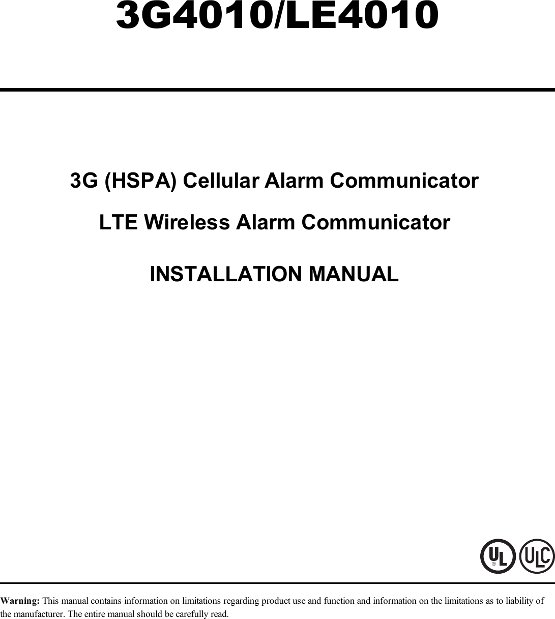
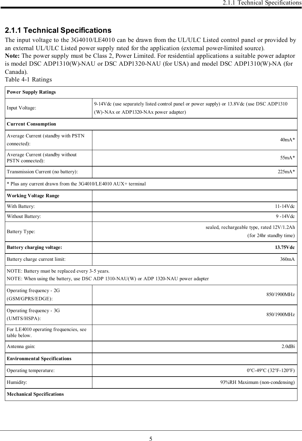
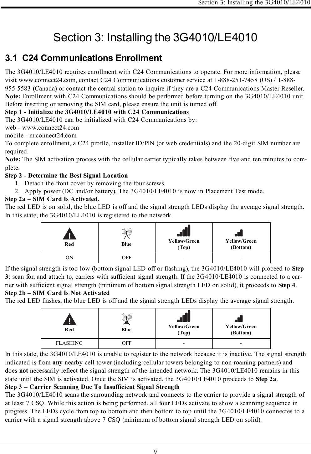
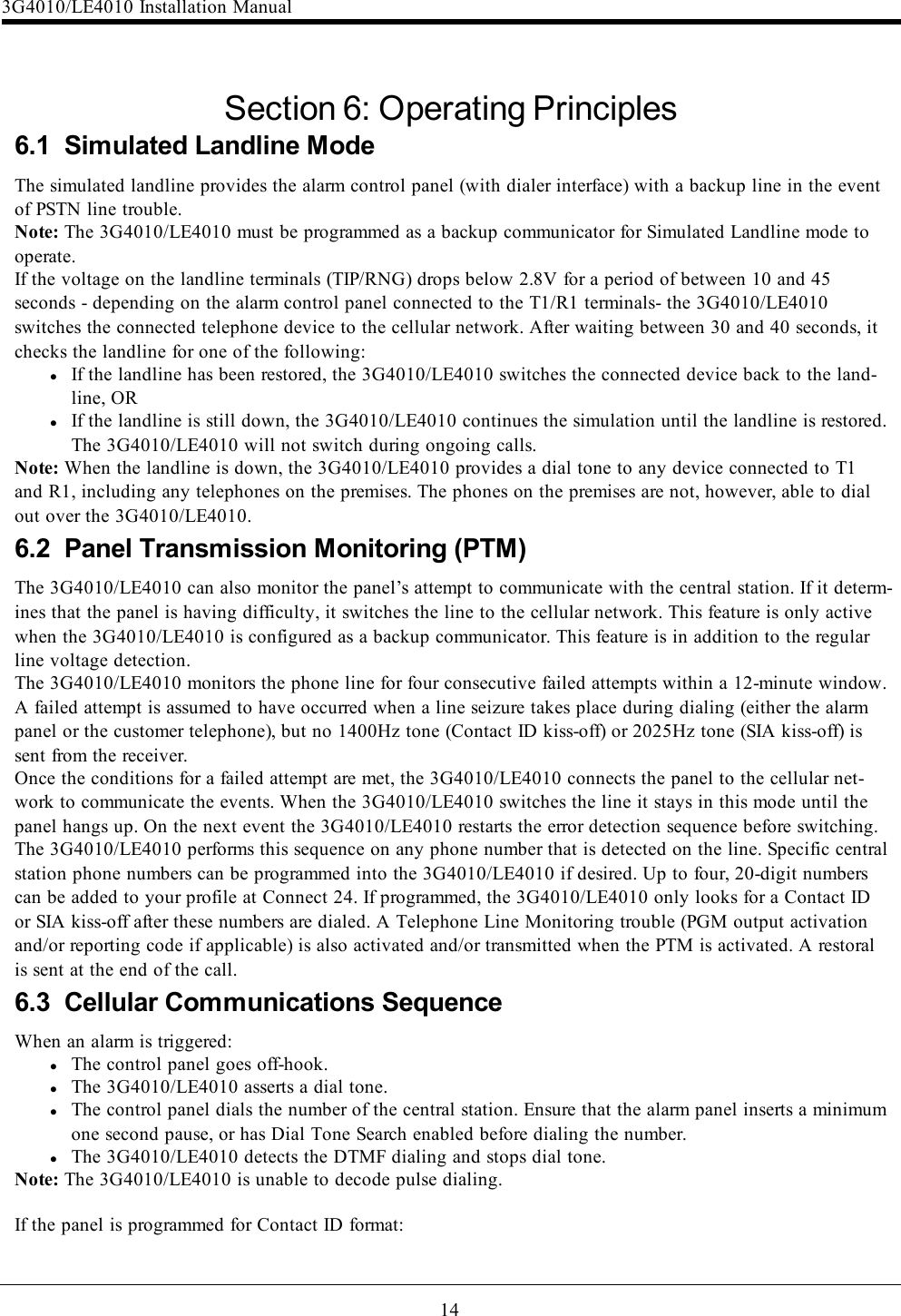
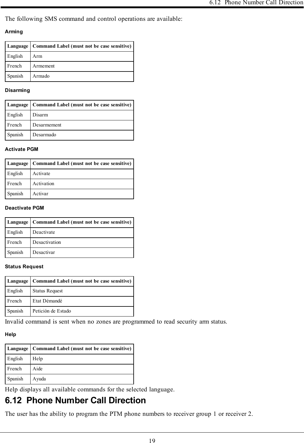
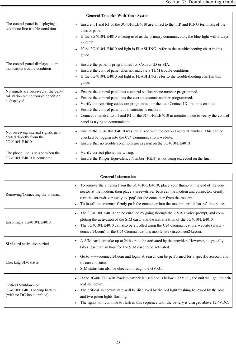
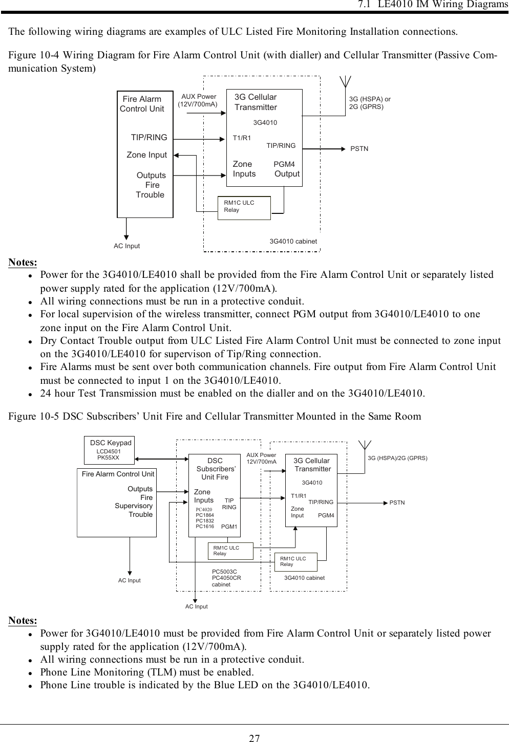
![11Section 4: Connecting the 3G4010/LE4010Red Blue Yellow/Green(Top)Yellow/Green(Bottom)ON ON ON FLASHING...and turns on solid when it receives a communication back from the central station.Red Blue Yellow/Green(Top)Yellow/Green(Bottom)ON ON ON ONIf at least one of the central stations does not respond back to the communicator, the signal strength LED cor-responding to that central station turns off. Once the initialization sequence is complete, the 3G4010/LE4010switches to steady state operation.Step 6 - Mount the 3G4010/LE40101. Power down the 3G4010/LE4010 by removing the DC power source and battery leads.2. Using the cabinet, mark the four screw locations. Drill the anchor screw holes.Note: Check for cable conduits and water pipes before drilling.3. Using anchor screws (not provided), mount the cabinet to the wall.4. Run the cables through the cable entry [13] or through the cabinet knockouts.5. Complete the connections on the terminal blocks [11].Note: Ensure that power and Telco circuit connections are made only after the cabinet has been secured to thebuilding or structure, and has been connected to the protective earth ground. Descriptions of the terminals canbe found in the ‘Connecting the 3G4010/LE4010’ section.6. Reattach the front cover [1] securely to the cabinet.Note: Please refer to the end of this manual for wiring diagrams.Section 4: Connecting the 3G4010/LE4010(1) Earth Ground - This terminal must be connected to the Mains Earth, in order to comply with the Tele-communications Network Safety Standards (Overvoltage Protection Requirements).TIP (2) / RNG (3) External Telephone Line - These terminals must be connected directly to the incoming tele-phone line.T1 (4) / R1 (5) Internal Telephone Line - These terminals must be connected to the TIP and RING of the con-trol panel.COM (6,12) Common - This terminal is connected internally to Power Ground.PGM1 (7), PGM2 (8), PGM3 (9), PGM4 (10) Programmable Open-collector Outputs - These outputs can beactivated by programmed events. Refer to ‘Activating the Outputs’ for details. The maximum current sink ofeach output must not exceed 50mA.AUX+ (11) Auxiliary Output - 9 to 14VDC Output, 500mA PTC Protected.Note: Electrical current drawn from this terminal is drawn directly from the power supply. This must be addedto the 3G4010/LE4010 current when determining the total draw on the host panel or power supply.Z1-Z4 (13-14-15-16) Programmable Inputs - These terminals can be set up to trigger events. Refer to ‘Inputs’for details.DC IN (17), (18) Device Power Supply - These terminals must be connected to a rated power supply. Ifthe primary supply does not include a backup battery, connect the battery leads (red and black wires, [12] inFigure 1) to a 12V, 1.2 Ah battery.](https://usermanual.wiki/Digital-Security-Controls/17LE4010.Installation-Manual/User-Guide-3680675-Page-11.png)
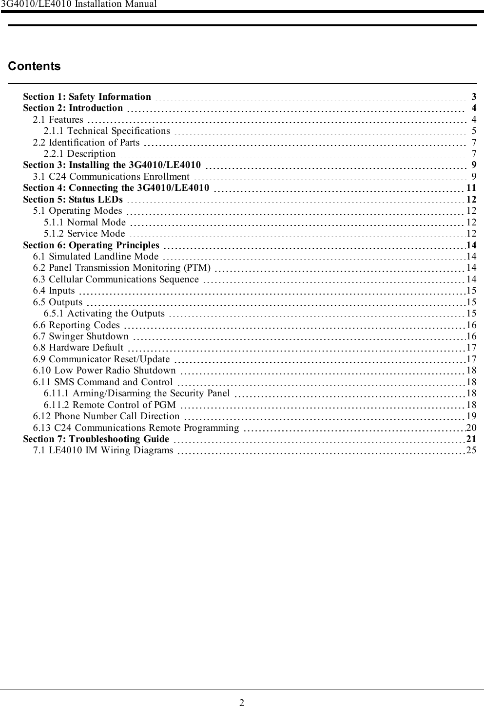
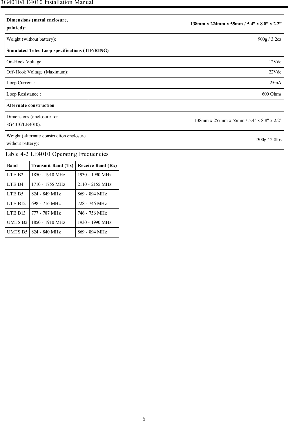
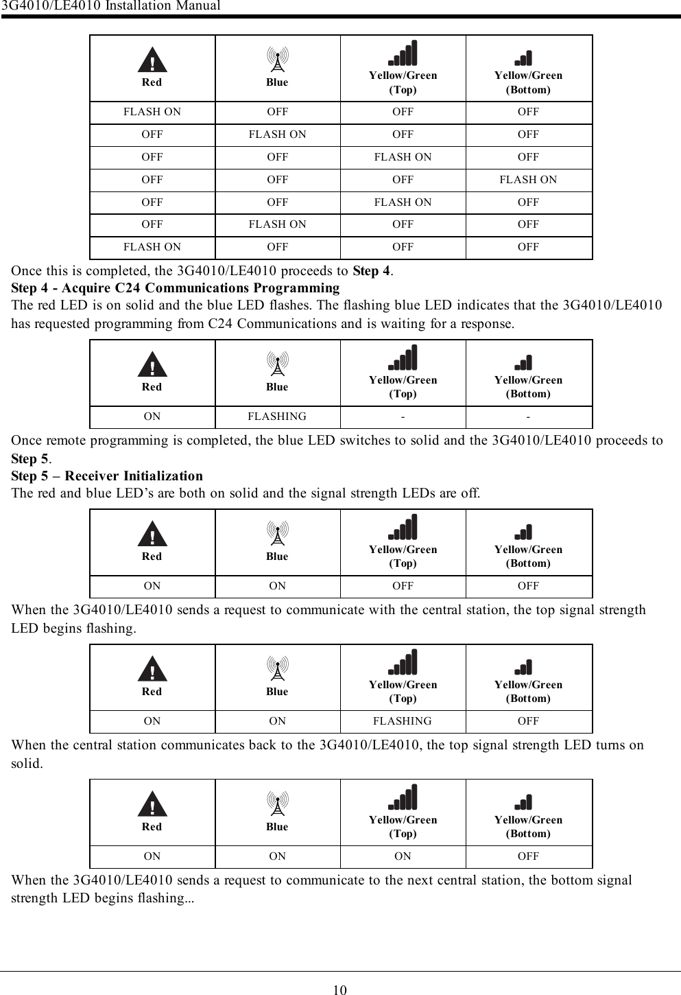
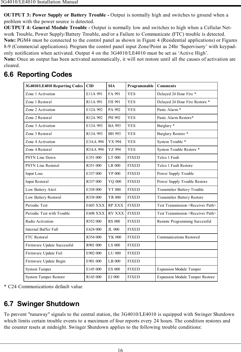
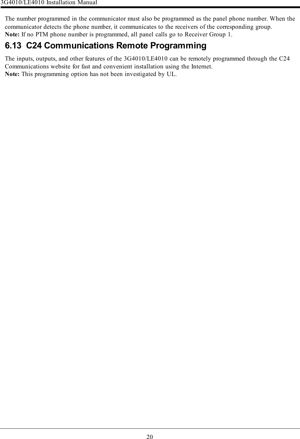
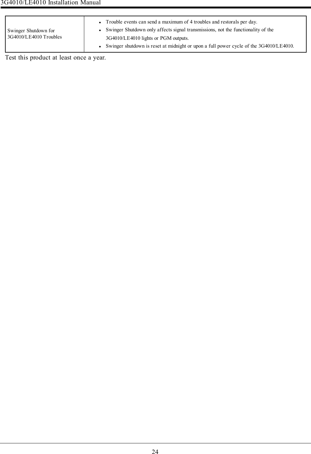
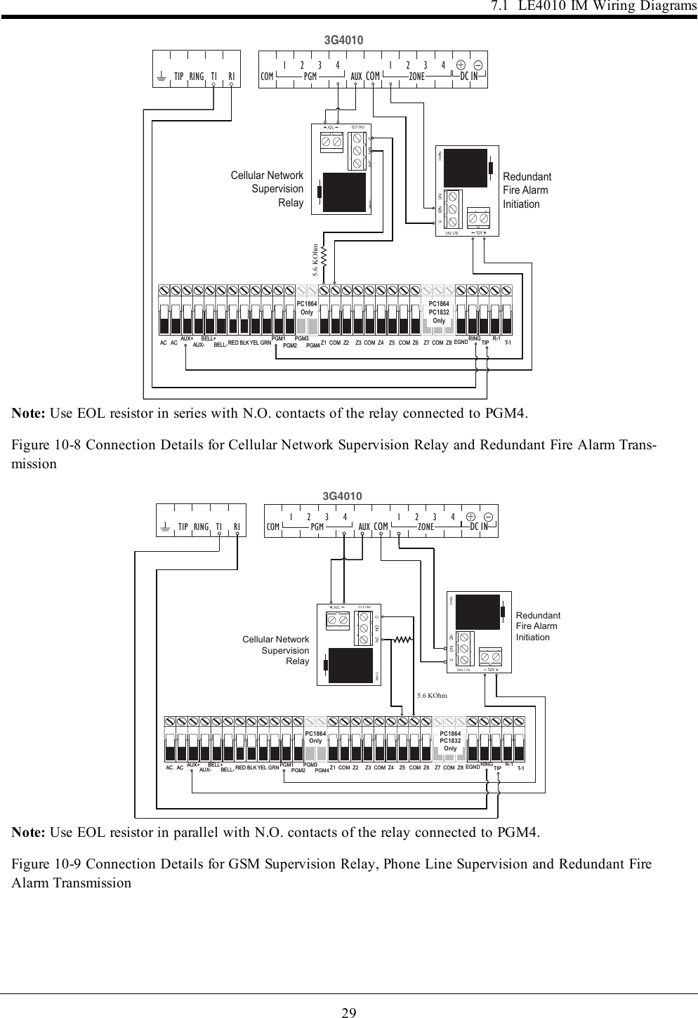
![156.4 InputslThe 3G4010/LE4010 sends the required Contact ID dual-tone handshake to the panel.lAfter receiving the handshake, the control panel transmits an alarm message in Contact ID format.lThe 3G4010/LE4010 decodes and transforms the Contact ID digits into an IP packet and sends it to thecentral station receiver over the cellular network.lThe central station receiver acknowledges the alarm and sends a command to the 3G4010/LE4010 togenerate the corresponding 1400Hz Kiss-off signal for a minimum of 800 milliseconds.After the 3G4010/LE4010 generates a Kiss-off signal, it sends the next alarm or, if no further alarms need to besent, the control panel goes on-hook.If the panel is programmed for SIA (300 baud) format:lThe 3G4010/LE4010 sends the required SIA handshake to the panel.lAfter receiving the handshake, the control panel transmits an alarm message in the SIA format.lThe 3G4010/LE4010 decodes and transforms the SIA events into an IP packet that it sends to the cent-ral station receiver over the cellular network.lThe central station’s receiver acknowledges the alarm and sends a command to the 3G4010/LE4010 togenerate the corresponding 2025Hz kiss-off signal for a minimum of one second.lAfter the 3G4010/LE4010 generates a kiss-off signal, it sends the next alarm or, if no further alarmsneed to be sent, the control panel goes on hook.Note: The 3G4010/LE4010 automatically adjusts the order of the handshakes based on the last format the con-trol panel used to transmit an event.6.4 InputsThe 3G4010/LE4010 has four inputs that can be used to trigger specific communications. These events trans-mit using the Contact ID or SIA format with Inputs 1-4 reporting as [991] to [994] respectively.Default settings are:INPUT 1- FIRE INPUT 3 - BURGLARYINPUT 2 - PANIC ALARM INPUT 4 - SYSTEM TROUBLEInputs can be configured as follows:Normally Open - input activates when a short condition is detected between the terminal and COMNormally Closed - input activates when an open condition is detected between the terminal and COMSingle End of Line - input activates when a short or open condition is detected between the terminal andCOM and restores when a 5.6Kohm resistor is detected between the terminal and COM.Note: These inputs are programmable to communicate using either the Contact ID or SIA format.Note: For UL/ULC installations, connections between alarm panel outputs and 3G4010/LE4010 inputs mustbe run in protective mechanical conduits. To reduce interference with the antenna, do not connect metal con-duit to the knock-outs in the top of the cabinet.6.5 OutputsThe 3G4010/LE4010 has four programmable outputs to activate in response to the associated events. Refer tothe 3G4010/LE4010 Wiring Diagram at the back of this manual.6.5.1 Activating the OutputsThe 3G4010/LE4010 has four open collector outputs capable of a maximum of 50mA. Internal events on the3G4010/LE4010 can trigger the outputs to turn on an LED or activate an input on the host panel. The defaultsettings are as follows.OUTPUT 1: Landline Trouble - Output is normally high and switchs to ground when the telephone line isdown.OUTPUT 2: Cellular Module or Network Trouble - Output is normally high and switches to ground whenthe 3G4010/LE4010 cannot communicate with the network.](https://usermanual.wiki/Digital-Security-Controls/17LE4010.Installation-Manual/User-Guide-3680675-Page-15.png)
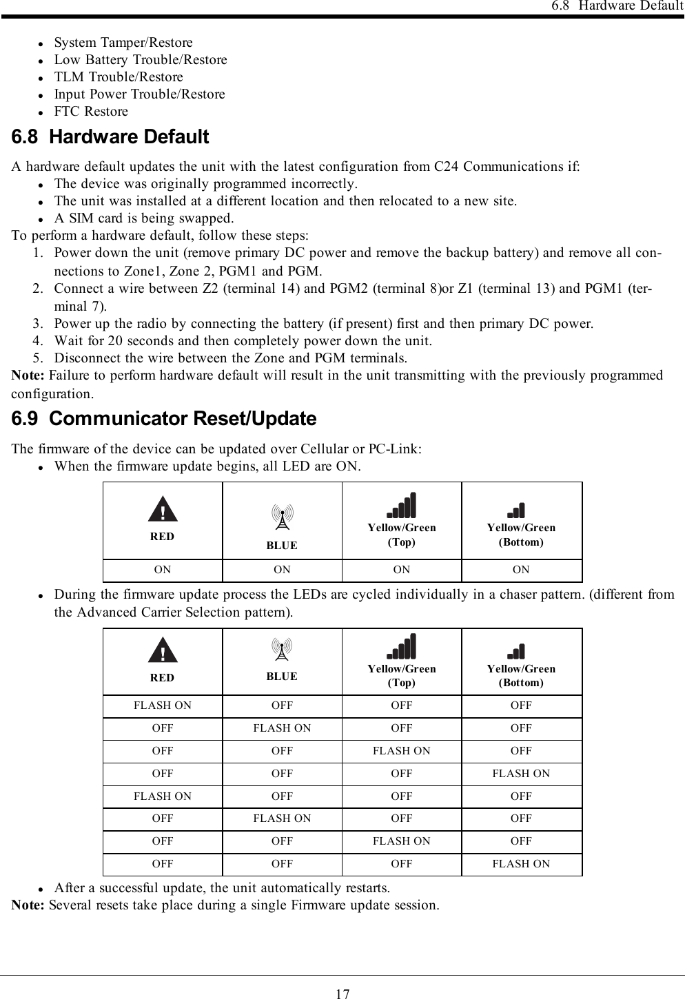
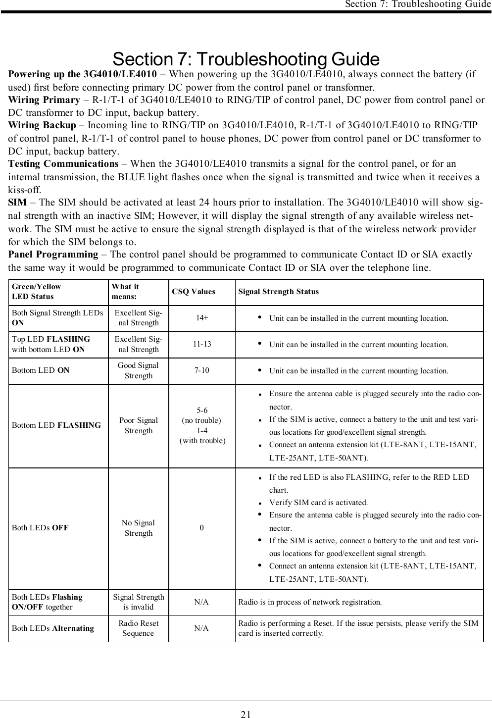
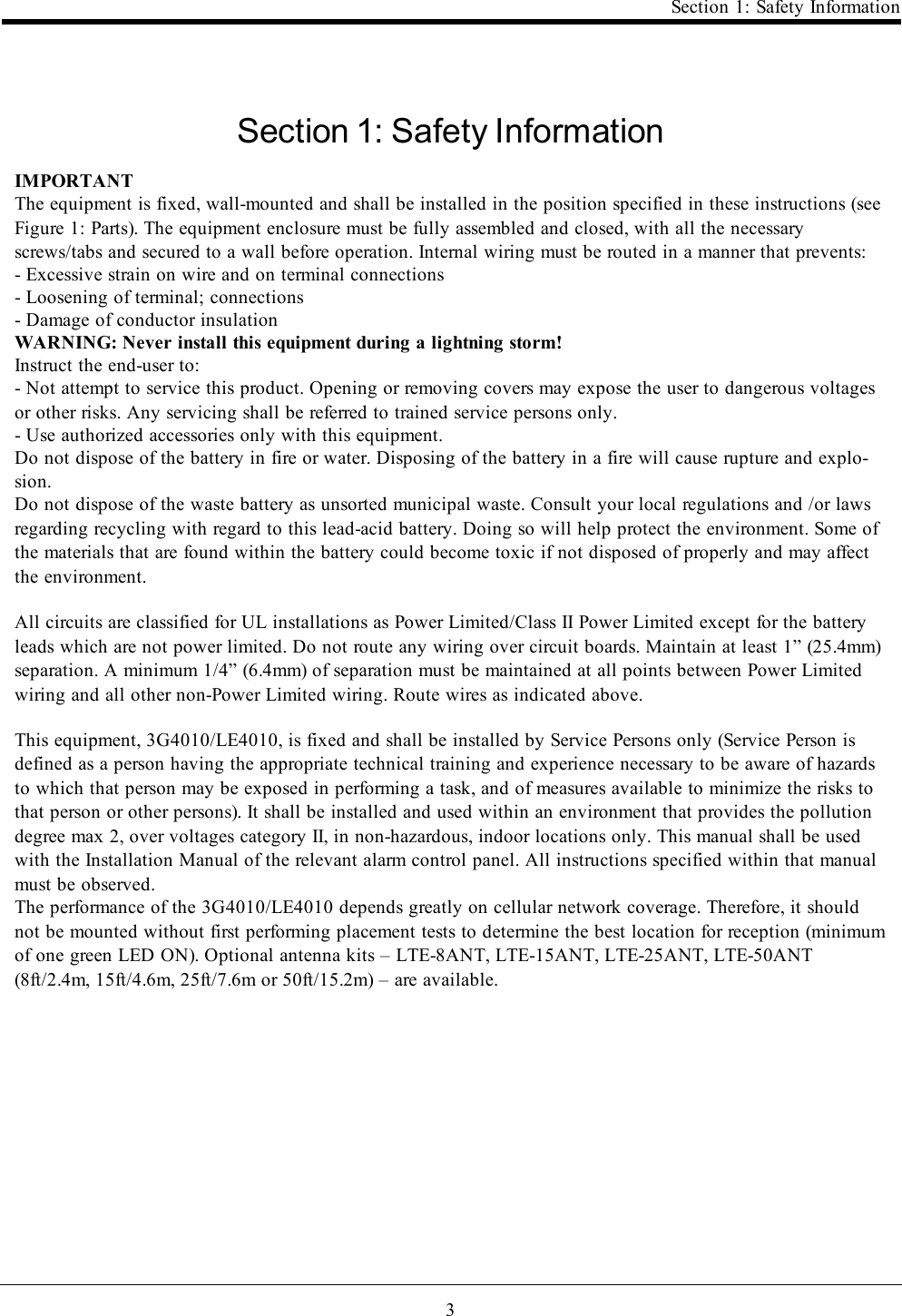
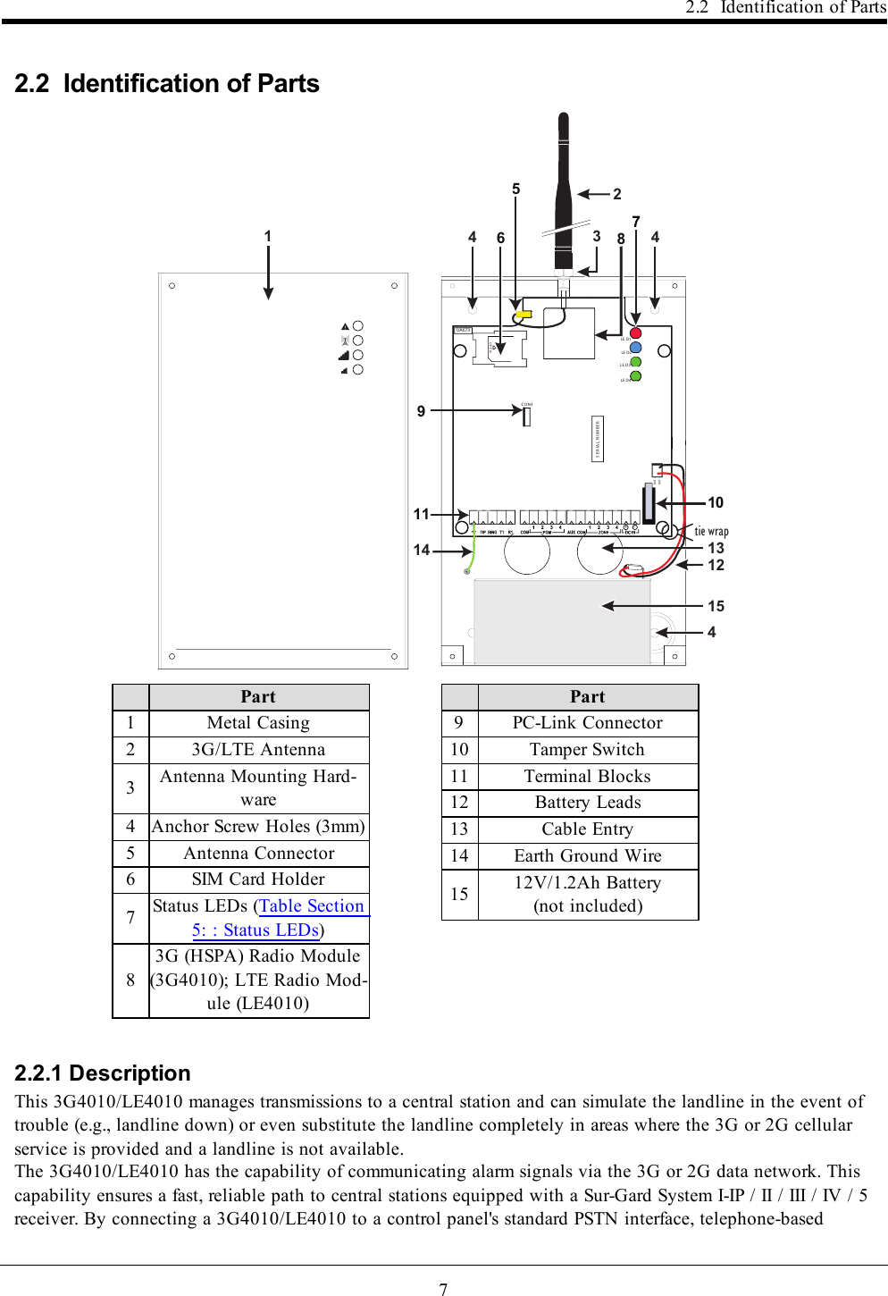
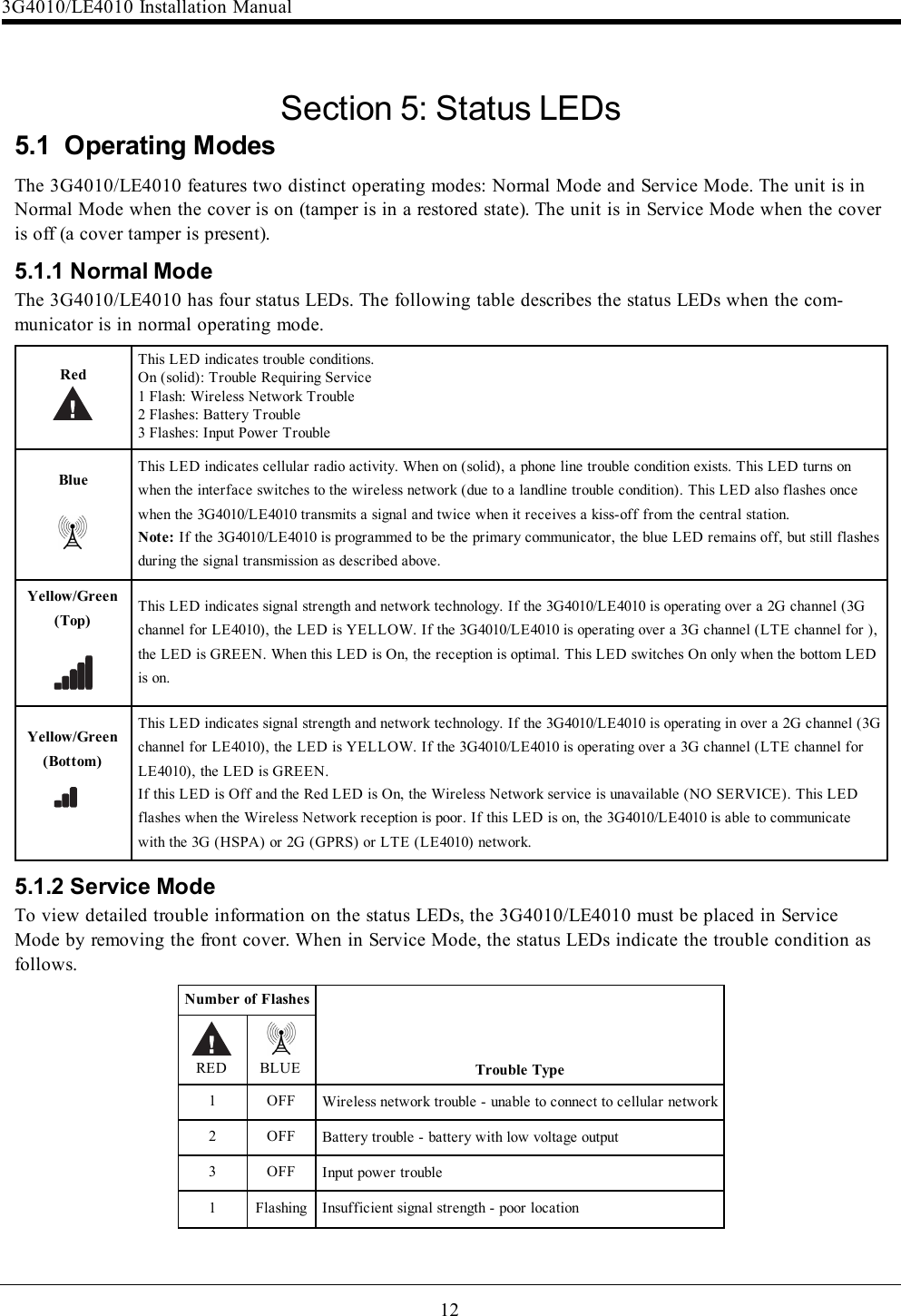
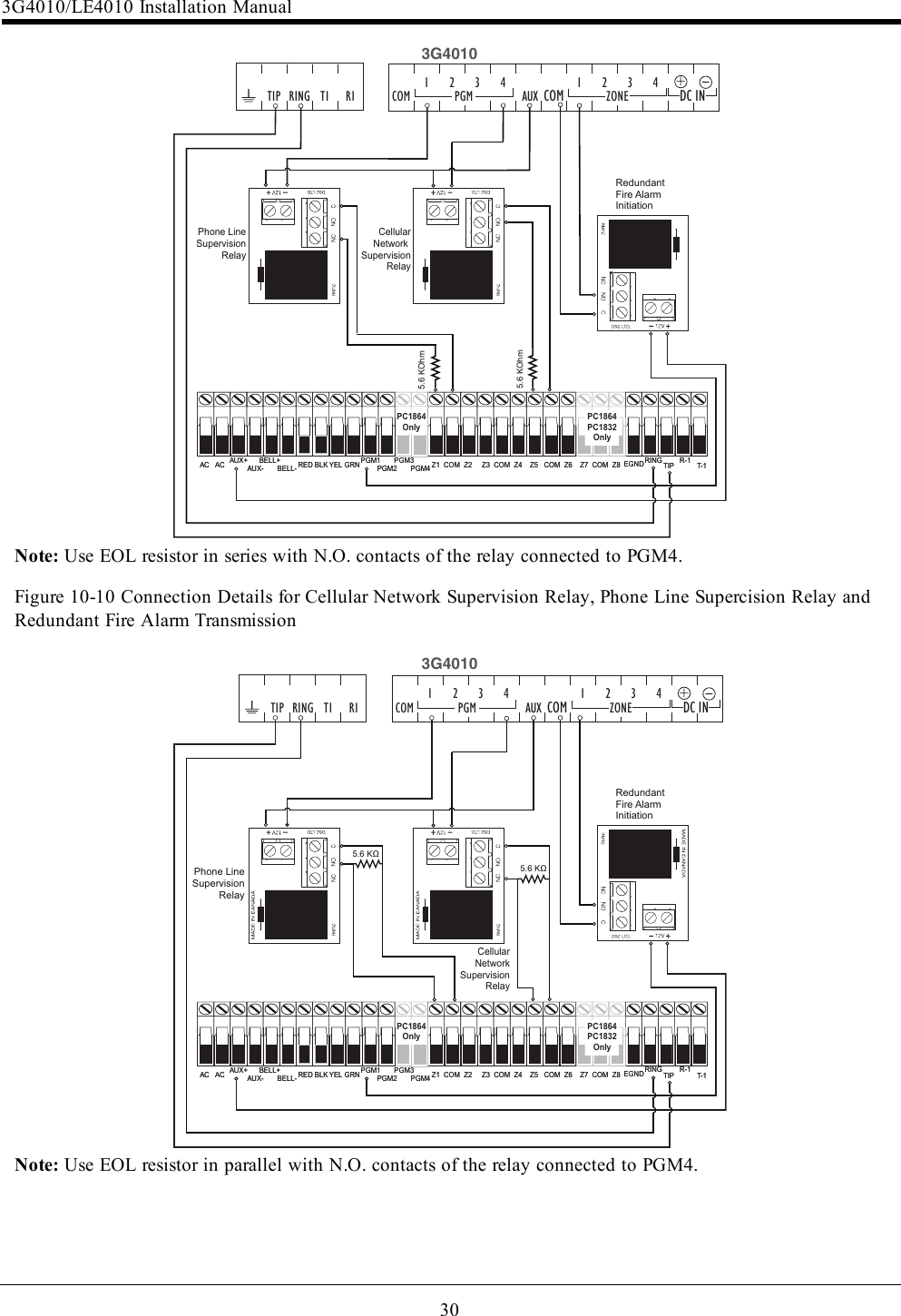
![28lConnect PGM4 output from the 3G4010/LE4010 (Trouble Conditions) to a zone input on the Sub-scriber Unit for supervision of the GSM Transmitter.l24hour Test Transmission over phone line (PSTN) and 3G4010/LE4010 must be enabled.lFire Alarm smust be sent over both communication channels.lOn the Subscribers’ Unit, program PGM1 for PC1616/PC1832/PC1864 as System Event (Section [009]as type 10; Section [501] Fire Event option 2 ON). An alternate option is to program PGM1 as ZoneFollower (Section [009] = 29) and assign Fire Zone to PGM1 in Section [551]. Ensure Bit 3 is on in[501]. In this case, a restored fire alarm condition does not require the DSC control panel to be reset.For PC4020, program PGM1 as type 49 Steady Fire ([00070049]).lDry contact outputs from ULC Listed Fire Alarm Control Unit must be connected to zone inputs on theULC Listed DSC subscribers' Unit Fire.lRefer to detailed diragrms.Figure 10-6 DSC Subscribers’ Unit Fire and 3G Cellular Transmitter Mounted RemotelyAlternate Wiring Diagram for DSC Subscribers' Unit Fire and Cellular Transmitter Passive Communication Sys-tem - Using Phone Line Supervision Relay Fire Alarm Control Unit Outputs FireSupervisory Trouble DSCSubscribers’ Unit FireZoneInputsTIPRING PGM1 DSC Keypad LCD4501 PK55XX3G CellularTransmitter 3G4010T1/R1 PGM1 TIP/RING Zone Input PGM4 AUX Power 12V/700mA RM1C ULC Relay PC5003CPC4050CRcabinet3G (HSPA)/2G (GPRS) PSTNAC Input AC Input PC4020 PC1864 PC1832 PC1616RM1C ULC Relay GS4010 cabinet RM1C ULC Relay PLEASE NOTE THAT EITHER RM1C ULC OR RM2 RELAYS CAN BE USED FOR ULCINSTALLATIONSNotes:lConnect PGM output from the 3G4010/LE4010 (Phone Line Trouble) to a zone input on the subscriberunit for supervision of the phone line voltage.lWhen the 3G4010/LE4010 is installed remotely from the DSC Control Panel, the Phone Line Troublecondition must be monitored at the keypad using an additional RM1C relay.Figure 10-7 Connection Details for Cellular Network Supervision Relay and Redundant Fire Alarm Trans-mission3G4010/LE4010 Installation Manual](https://usermanual.wiki/Digital-Security-Controls/17LE4010.Installation-Manual/User-Guide-3680675-Page-28.png)
![© 2017 Tyco Security Products. All Rights Reserved.Tech Support: 1-800-387-3630 (Canada & U.S.) or 905-760-3000www.dsc.comThe trademarks, logos, and service marks displayed on this document are registered in the United States [or other countries]. Any misuse of the trademarks is strictlyprohibited and Tyco will aggressively enforce its intellectual property rights to the fullest extent of the law, including pursuit of criminal prosecution wherever necessary. Alltrademarks not owned by Tyco are the property of their respective owners, and are used with permission or allowed under applicable laws.Product offerings and specifications are subject to change without notice. Actual products may vary from photos. Not all products include all features. Availability varies byregion; contact your sales representative.](https://usermanual.wiki/Digital-Security-Controls/17LE4010.Installation-Manual/User-Guide-3680675-Page-35.png)