Digital Security Controls 17LE4010 LTE Cellular Alarm Communicator User Manual My
Digital Security Controls Ltd. LTE Cellular Alarm Communicator My
Contents
- 1. RI7LE910NAV2 User Manual
- 2. Installation Manual
Installation Manual

3G4010/LE4010
3G (HSPA) Cellular Alarm Communicator
LTE Wireless Alarm Communicator
INSTALLATION MANUAL
Warning: This manual contains information on limitations regarding product use and function and information on the limitations as to liability of
the manufacturer. The entire manual should be carefully read.

2
Contents
Section 1: Safety Information 3
Section 2: Introduction 4
2.1 Features 4
2.1.1 Technical Specifications 5
2.2 Identification of Parts 7
2.2.1 Description 7
Section 3: Installing the 3G4010/LE4010 9
3.1 C24 Communications Enrollment 9
Section 4: Connecting the 3G4010/LE4010 11
Section 5: Status LEDs 12
5.1 Operating Modes 12
5.1.1 Normal Mode 12
5.1.2 Service Mode 12
Section 6: Operating Principles 14
6.1 Simulated Landline Mode 14
6.2 Panel Transmission Monitoring (PTM) 14
6.3 Cellular Communications Sequence 14
6.4 Inputs 15
6.5 Outputs 15
6.5.1 Activating the Outputs 15
6.6 Reporting Codes 16
6.7 Swinger Shutdown 16
6.8 Hardware Default 17
6.9 Communicator Reset/Update 17
6.10 Low Power Radio Shutdown 18
6.11 SMS Command and Control 18
6.11.1 Arming/Disarming the Security Panel 18
6.11.2 Remote Control of PGM 18
6.12 Phone Number Call Direction 19
6.13 C24 Communications Remote Programming 20
Section 7: Troubleshooting Guide 21
7.1 LE4010 IM Wiring Diagrams 25
3G4010/LE4010 Installation Manual

3
Section 1: Safety Information
Section 1: Safety Information
IMPORTANT
The equipment is fixed, wall-mounted and shall be installed in the position specified in these instructions (see
Figure 1: Parts). The equipment enclosure must be fully assembled and closed, with all the necessary
screws/tabs and secured to a wall before operation. Internal wiring must be routed in a manner that prevents:
- Excessive strain on wire and on terminal connections
- Loosening of terminal; connections
- Damage of conductor insulation
WARNING: Never install this equipment during a lightning storm!
Instruct the end-user to:
- Not attempt to service this product. Opening or removing covers may expose the user to dangerous voltages
or other risks. Any servicing shall be referred to trained service persons only.
- Use authorized accessories only with this equipment.
Do not dispose of the battery in fire or water. Disposing of the battery in a fire will cause rupture and explo-
sion.
Do not dispose of the waste battery as unsorted municipal waste. Consult your local regulations and /or laws
regarding recycling with regard to this lead-acid battery. Doing so will help protect the environment. Some of
the materials that are found within the battery could become toxic if not disposed of properly and may affect
the environment.
All circuits are classified for UL installations as Power Limited/Class II Power Limited except for the battery
leads which are not power limited. Do not route any wiring over circuit boards. Maintain at least 1” (25.4mm)
separation. A minimum 1/4” (6.4mm) of separation must be maintained at all points between Power Limited
wiring and all other non-Power Limited wiring. Route wires as indicated above.
This equipment, 3G4010/LE4010, is fixed and shall be installed by Service Persons only (Service Person is
defined as a person having the appropriate technical training and experience necessary to be aware of hazards
to which that person may be exposed in performing a task, and of measures available to minimize the risks to
that person or other persons). It shall be installed and used within an environment that provides the pollution
degree max 2, over voltages category II, in non-hazardous, indoor locations only. This manual shall be used
with the Installation Manual of the relevant alarm control panel. All instructions specified within that manual
must be observed.
The performance of the 3G4010/LE4010 depends greatly on cellular network coverage. Therefore, it should
not be mounted without first performing placement tests to determine the best location for reception (minimum
of one green LED ON). Optional antenna kits – LTE-8ANT, LTE-15ANT, LTE-25ANT, LTE-50ANT
(8ft/2.4m, 15ft/4.6m, 25ft/7.6m or 50ft/15.2m) – are available.

4
Section 2: Introduction
This manual covers two communicator models, the 3G4010 and the LE4010. They are referred to throughout
this manual as 3G4010/LE4010 unless otherwise indicated.
Both models send alarm system information to a Sur-Gard System I-IP, II, III, IV or 5 receiver. The 3G4010
uses the 3G (HSPA) or 2G (GPRS) cellular network. The LE4010 uses the LTE or 3G wireless network. The
3G4010/LE4010 can be used with UL/ULC Listed compatible control units, as indicated in the manufacturer's
installation instructions.
Note: These communicators are designed to work with the Contact ID communication format as described in
the SIA DC-05 standard and the SIA DC-03 standard for 300 baud. Before completing the field installation of
the alarm monitoring system please ensure communication with the supervising central station is successful by
sending several events and getting confirmation that they have been received.
2.1 Features
lDual-band UMTS/HSPA; Penta-Band LTE (LE4010); Quad-Band GSM/EDGE Radio
lAdvanced Carrier Selection
lBi-color Wireless Signal Strength Indicator
l3G (HSPA) / 2G (GPRS) ; LTE or 3G (LE4010) Internet communication with Sur-Gard SG-System I-IP
/ II / III / IV / 5
lCompatible with 4-digit or 10-digit Contact ID communication format as described in SIA DC-05
Standard and the SIA DC-03 standard for 300 baud. Example of suitable compatible alarm panels:
DSC Models PC1864, PC1832, PC1616, PC4020. For LE4010, the following alarm panels are also com-
patible: HS2128, HS2064, HS2032, HS2016
lPanel Transmission Monitoring for up to four phone numbers
lSimulates landline
lSwitches automatically to the 3G (HSPA) or 2G (GPRS) / LTE or 3G (LE4010) network in the event of
landline trouble (e.g., line down)
lFour Programmable (NO/NC/SEOL) Inputs
l12V 1.2Ah battery (optional, not included)
lCase Tamper Output
lLandline overvoltage protection
lFour Programmable Outputs
lDLS support for status, firmware updates and remote debug enable
lRemote Firmware Upgrade
lRemote Diagnostics
lPanel Format Detection
lSMS Command and Control
lPhone number call direction
lEasy enrollment with C24 Communications via web or mobile interface
3G4010/LE4010 Installation Manual
5
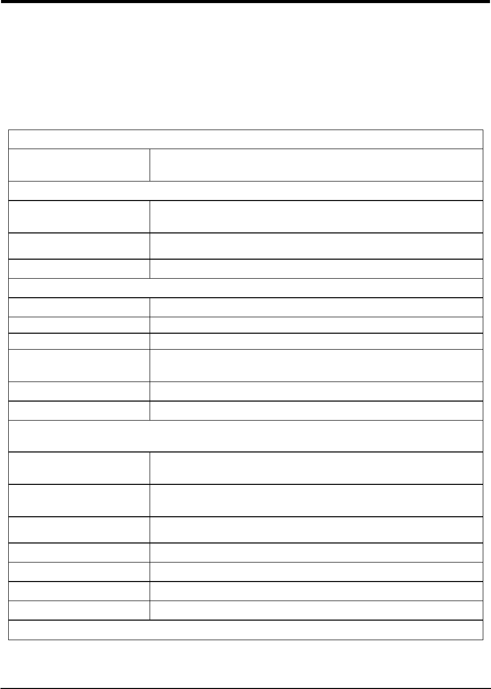
2.1.1 Technical Specifications
2.1.1 Technical Specifications
The input voltage to the 3G4010/LE4010 can be drawn from the UL/ULC Listed control panel or provided by
an external UL/ULC Listed power supply rated for the application (external power-limited source).
Note: The power supply must be Class 2, Power Limited. For residential applications a suitable power adaptor
is model DSC ADP1310(W)-NAU or DSC ADP1320-NAU (for USA) and model DSC ADP1310(W)-NA (for
Canada).
Table 4-1 Ratings
Power Supply Ratings
Input Voltage: 9-14Vdc (use separately listed control panel or power supply) or 13.8Vdc (use DSC ADP1310
(W)-NAx or ADP1320-NAx power adapter)
Current Consumption
Average Current (standby with PSTN
connected): 40mA*
Average Current (standby without
PSTN connected): 55mA*
Transmission Current (no battery): 225mA*
* Plus any current drawn from the 3G4010/LE4010 AUX+ terminal
Working Voltage Range
With Battery: 11-14Vdc
Without Battery: 9 -14Vdc
Battery Type: sealed, rechargeable type, rated 12V/1.2Ah
(for 24hr standby time)
Battery charging voltage: 13.75Vdc
Battery charge current limit: 360mA
NOTE: Battery must be replaced every 3-5 years.
NOTE: When using the battery, use DSCADP 1310-NAU(W) or ADP 1320-NAU power adapter
Operating frequency - 2G
(GSM/GPRS/EDGE): 850/1900MHz
Operating frequency - 3G
(UMTS/HSPA): 850/1900MHz
For LE4010 operating frequencies, see
table below.
Antenna gain: 2.0dBi
Environmental Specifications
Operating temperature: 0°C-49°C (32°F-120°F)
Humidity: 93%RH Maximum (non-condensing)
Mechanical Specifications
6
Dimensions (metal enclosure,
painted): 138mm x 224mm x 55mm / 5.4” x 8.8” x 2.2”
Weight (without battery): 900g / 3.2oz
Simulated Telco Loop specifications (TIP/RING)
On-Hook Voltage: 12Vdc
Off-Hook Voltage (Maximum): 22Vdc
Loop Current : 25mA
Loop Resistance : 600 Ohms
Alternate construction
Dimensions (enclosure for
3G4010/LE4010): 138mm x 257mm x 55mm / 5.4" x 8.8" x 2.2"
Weight (alternate construction enclosure
without battery): 1300g / 2.8lbs
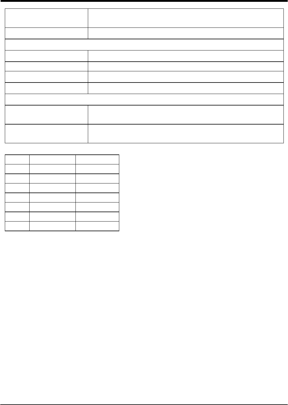
Table 4-2 LE4010 Operating Frequencies
Band Transmit Band (Tx) Receive Band (Rx)
LTE B2 1850 - 1910 MHz 1930 - 1990 MHz
LTE B4 1710 - 1755 MHz 2110 - 2155 MHz
LTE B5 824 - 849 MHz 869 - 894 MHz
LTE B12 698 - 716 MHz 728 - 746 MHz
LTE B13 777 - 787 MHz 746 - 756 MHz
UMTS B2 1850 - 1910 MHz 1930 - 1990 MHz
UMTS B5 824 - 840 MHz 869 - 894 MHz
3G4010/LE4010 Installation Manual
7
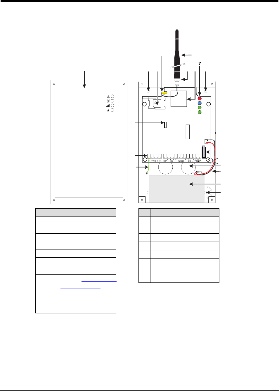
2.2 Identification of Parts
2.2 Identification of Parts
C ON 3
LE D2
B A T +
OP E N
+
LE D1
B A T -
-
LE D4
LE D3
UA673
S E RIA L NU MB E R
144
5
3
2
8
6
9
10
11
13
12
15
14
4
tie wrap
Part
1 Metal Casing
2 3G/LTE Antenna
3Antenna Mounting Hard-
ware
4 Anchor Screw Holes (3mm)
5 Antenna Connector
6 SIM Card Holder
7Status LEDs (Table Section
5: : Status LEDs)
8
3G (HSPA) Radio Module
(3G4010); LTE Radio Mod-
ule (LE4010)
Part
9 PC-Link Connector
10 Tamper Switch
11 Terminal Blocks
12 Battery Leads
13 Cable Entry
14 Earth Ground Wire
15 12V/1.2Ah Battery
(not included)
2.2.1 Description
This 3G4010/LE4010 manages transmissions to a central station and can simulate the landline in the event of
trouble (e.g., landline down) or even substitute the landline completely in areas where the 3G or 2G cellular
service is provided and a landline is not available.
The 3G4010/LE4010 has the capability of communicating alarm signals via the 3G or 2G data network. This
capability ensures a fast, reliable path to central stations equipped with a Sur-Gard System I-IP / II / III / IV / 5
receiver. By connecting a 3G4010/LE4010 to a control panel's standard PSTN interface, telephone-based

8
Contact ID or SIA signals are decoded and seamlessly routed through the LTE, 3G or 2G network to any of
the compatible receiver options.
The performance of the 3G4010/LE4010 depends greatly on cellular network coverage. Therefore, it should
not be mounted without first performing placement tests to determine the best location for reception (minimum
of one green LED ON). Optional antenna kits – LTE-8ANT (8ft/2.4m), LTE-15ANT (15ft/4.6m), LTE-25ANT
(25ft/7.6m) and LTE-50ANT (50ft/15.2m) – are available.
For UL Residential Fire and Burglary installations, the 3G4010/LE4010 is listed as a sole means of com-
munication or as a back up when used in conjunction with a POTS line (dialer).
For UL Commercial Burglary installations, the 3G4010/LE4010 is listed as a sole means of communication
(supervision window of 200s required at monitoring station) or as a back-up when used in conjunction with a
POTS line (dialer). The 3G4010/LE4010 shall be powered from any compatible listed control unit or com-
patible listed power supply that complies with the ratings specified on page 1. The power supply shall be lis-
ted for burglary applications and provide a minimum of 4 hours standby power capabilities. An example of a
suitable listed compatible control unit is the DSC Model HS2128 with an AUX output rated 11.1 - 12.6VDC.
An example of a suitable Listed power supply is DSC Model HSM2204 with an AUX output rated 11.6 -
12.6VDC.
For ULC Commercial Fire Monitoring Installations the 3G4010/LE4010 can be used in the following configurations:
1. Active communication system with 180 seconds supervision (Heartbeat sent to signal receiving centre
every 90 sec.).
2. Passive communication system in conjunction with a another communication path (e.g. DACT) (there is
no heartbeat sent in this configuration, only periodic test transmission ). Alarm signals must be sent sim-
ultaneously over both communication paths (Cellular and DACT). Every 24 hours, a test transmission
must be sent to the signal receiving centre over each communication path. Each communication path
shall be monitored for integrity (DACT shall have line monitoring enabled and 3G4010/LE4010 shall
have cellular connection supervision enabled).
For ULC Commercial Burglary Monitoring Installations the 3G4010/LE4010 can be used in the following
configurations:
1. Active communication system with 180 seconds supervision and heartbeat sent to signal receiving
centre every 90 sec.
2. Passive communication system line security P1 (single communication channel) or line security P2
(used as backup in conjunction with another communication path (e.g. DACT)). There is no heartbeat
sent in this configuration, only periodic test transmissions. Every 24 hours, a test transmission must be
sent to the signal receiving centre over each communication path. Each communication path shall be
monitored for integrity (DACT shall have line monitoring enabled and 3G4010/LE4010 shall have cel-
lular connection supervision enabled). For Level P2 the working communication path shall report the
failure of the other channel within 240s.
For ULC Residential Fire and Burglary installations the 3G4010/LE4010 is listed as a sole means com-
munication or as a back up when used in conjunction with a POTS line (dialer).
3G4010/LE4010 Installation Manual
9
Section 3: Installing the 3G4010/LE4010
Section 3: Installing the 3G4010/LE4010
3.1 C24 Communications Enrollment
The 3G4010/LE4010 requires enrollment with C24 Communications to operate. For more information, please
visit www.connect24.com, contact C24 Communications customer service at 1-888-251-7458 (US) / 1-888-
955-5583 (Canada) or contact the central station to inquire if they are a C24 Communications Master Reseller.
Note: Enrollment with C24 Communications should be performed before turning on the 3G4010/LE4010 unit.
Before inserting or removing the SIM card, please ensure the unit is turned off.
Step 1 - Initialize the 3G4010/LE4010 with C24 Communications
The 3G4010/LE4010 can be initialized with C24 Communications by:
web - www.connect24.com
mobile - m.connect24.com
To complete enrollment, a C24 profile, installer ID/PIN (or web credentials) and the 20-digit SIM number are
required.
Note: The SIM activation process with the cellular carrier typically takes between five and ten minutes to com-
plete.
Step 2 - Determine the Best Signal Location
1. Detach the front cover by removing the four screws.
2. Apply power (DC and/or battery). The 3G4010/LE4010 is now in Placement Test mode.
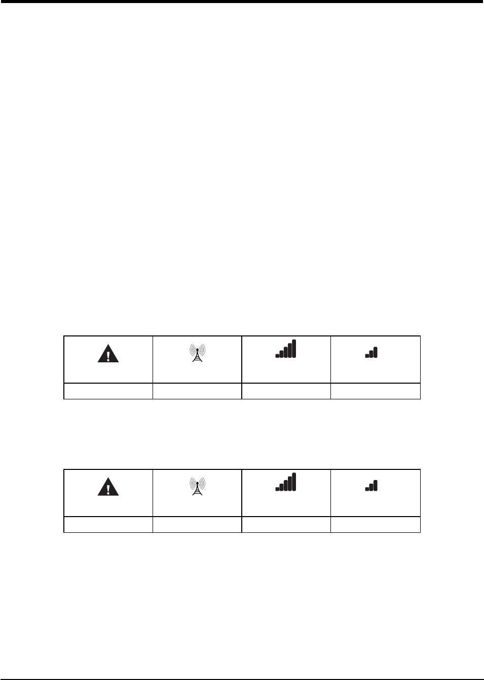
Step 2a – SIM Card Is Activated.
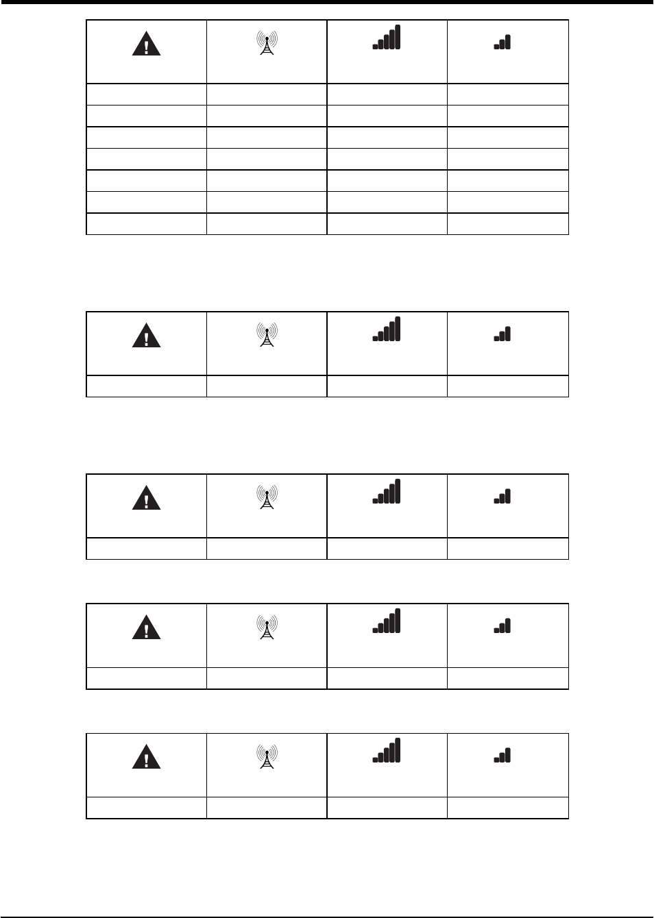
The red LED is on solid, the blue LED is off and the signal strength LEDs display the average signal strength.
In this state, the 3G4010/LE4010 is registered to the network.
Red Blue Yellow/Green
(Top)
Yellow/Green
(Bottom)
ON OFF - -
If the signal strength is too low (bottom signal LED off or flashing), the 3G4010/LE4010 will proceed to Step
3: scan for, and attach to, carriers with sufficient signal strength. If the 3G4010/LE4010 is connected to a car-
rier with sufficient signal strength (minimum of bottom signal strength LED on solid), it proceeds to Step 4.
Step 2b – SIM Card Is Not Activated
The red LED flashes, the blue LED is off and the signal strength LEDs display the average signal strength.
Red Blue Yellow/Green
(Top)
Yellow/Green
(Bottom)
FLASHING OFF - -
In this state, the 3G4010/LE4010 is unable to register to the network because it is inactive. The signal strength
indicated is from any nearby cell tower (including cellular towers belonging to non-roaming partners) and
does not necessarily reflect the signal strength of the intended network. The 3G4010/LE4010 remains in this
state until the SIM is activated. Once the SIM is activated, the 3G4010/LE4010 proceeds to Step 2a.
Step 3 – Carrier Scanning Due To Insufficient Signal Strength
The 3G4010/LE4010 scans the surrounding network and connects to the carrier to provide a signal strength of
at least 7 CSQ. While this action is being performed, all four LEDs activate to show a scanning sequence in
progress. The LEDs cycle from top to bottom and then bottom to top until the 3G4010/LE4010 connectes to a
carrier with a signal strength above 7 CSQ (minimum of bottom signal strength LED on solid).
10
Red Blue Yellow/Green
(Top)
Yellow/Green
(Bottom)
FLASH ON OFF OFF OFF
OFF FLASH ON OFF OFF
OFF OFF FLASH ON OFF
OFF OFF OFF FLASH ON
OFF OFF FLASH ON OFF
OFF FLASH ON OFF OFF
FLASH ON OFF OFF OFF
Once this is completed, the 3G4010/LE4010 proceeds to Step 4.
Step 4 - Acquire C24 Communications Programming
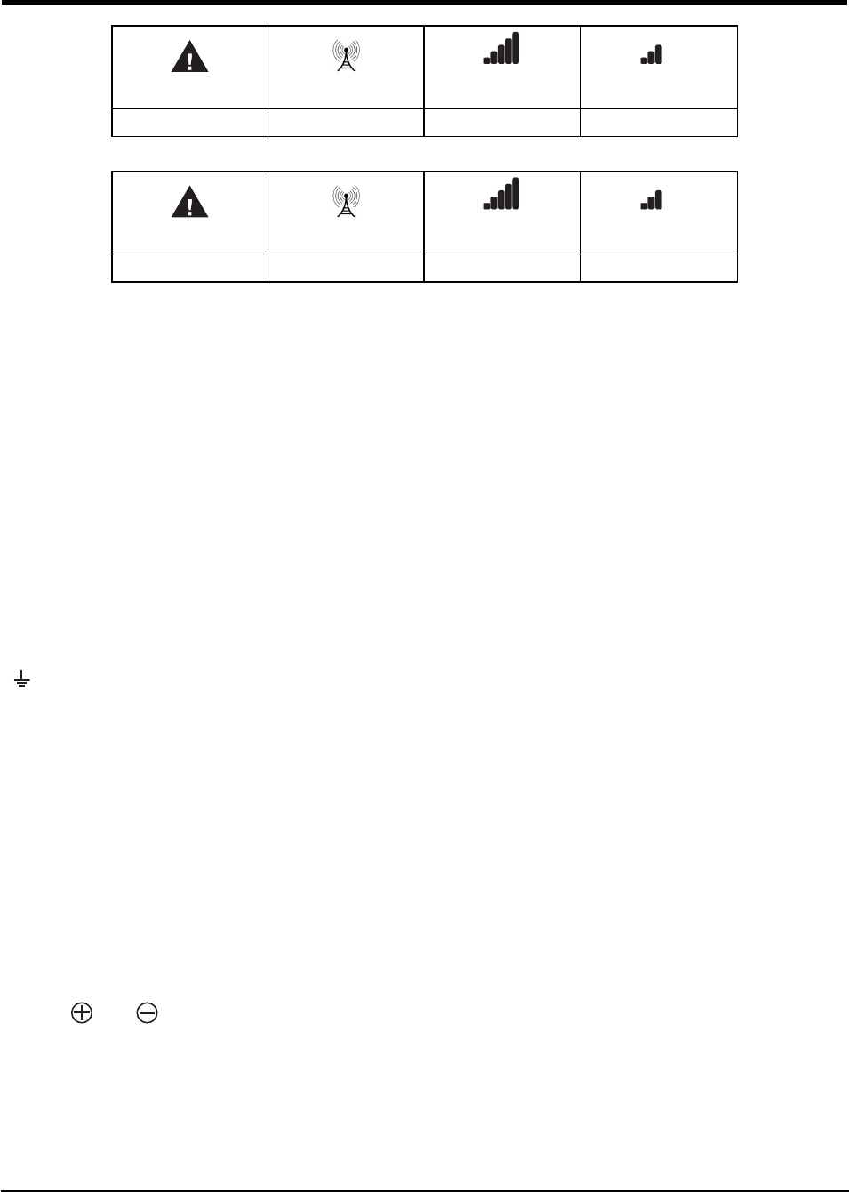
The red LED is on solid and the blue LED flashes. The flashing blue LED indicates that the 3G4010/LE4010
has requested programming from C24 Communications and is waiting for a response.
Red Blue Yellow/Green
(Top)
Yellow/Green
(Bottom)
ON FLASHING - -
Once remote programming is completed, the blue LED switches to solid and the 3G4010/LE4010 proceeds to
Step 5.
Step 5 – Receiver Initialization
The red and blue LED’s are both on solid and the signal strength LEDs are off.
Red Blue Yellow/Green
(Top)
Yellow/Green
(Bottom)
ON ON OFF OFF
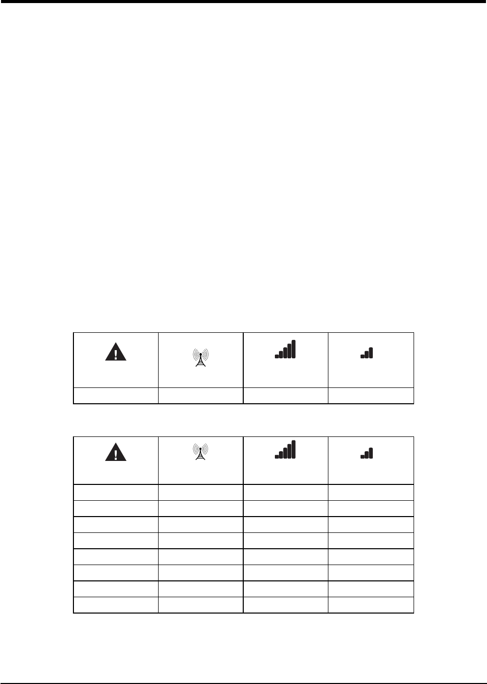
When the 3G4010/LE4010 sends a request to communicate with the central station, the top signal strength
LED begins flashing.
Red Blue Yellow/Green
(Top)
Yellow/Green
(Bottom)
ON ON FLASHING OFF
When the central station communicates back to the 3G4010/LE4010, the top signal strength LED turns on
solid.
Red Blue Yellow/Green
(Top)
Yellow/Green
(Bottom)
ON ON ON OFF
When the 3G4010/LE4010 sends a request to communicate to the next central station, the bottom signal
strength LED begins flashing...
3G4010/LE4010 Installation Manual
11
Section 4: Connecting the 3G4010/LE4010
Red Blue Yellow/Green
(Top)
Yellow/Green
(Bottom)
ON ON ON FLASHING
...and turns on solid when it receives a communication back from the central station.
Red Blue Yellow/Green
(Top)
Yellow/Green
(Bottom)
ON ON ON ON
If at least one of the central stations does not respond back to the communicator, the signal strength LED cor-
responding to that central station turns off. Once the initialization sequence is complete, the 3G4010/LE4010
switches to steady state operation.
Step 6 - Mount the 3G4010/LE4010
1. Power down the 3G4010/LE4010 by removing the DC power source and battery leads.
2. Using the cabinet, mark the four screw locations. Drill the anchor screw holes.
Note: Check for cable conduits and water pipes before drilling.
3. Using anchor screws (not provided), mount the cabinet to the wall.
4. Run the cables through the cable entry [13] or through the cabinet knockouts.
5. Complete the connections on the terminal blocks [11].
Note: Ensure that power and Telco circuit connections are made only after the cabinet has been secured to the
building or structure, and has been connected to the protective earth ground. Descriptions of the terminals can
be found in the ‘Connecting the 3G4010/LE4010’ section.
6. Reattach the front cover [1] securely to the cabinet.
Note: Please refer to the end of this manual for wiring diagrams.
Section 4: Connecting the 3G4010/LE4010
(1) Earth Ground - This terminal must be connected to the Mains Earth, in order to comply with the Tele-
communications Network Safety Standards (Overvoltage Protection Requirements).
TIP (2) / RNG (3) External Telephone Line - These terminals must be connected directly to the incoming tele-
phone line.
T1 (4) / R1 (5) Internal Telephone Line - These terminals must be connected to the TIP and RING of the con-
trol panel.
COM (6,12) Common - This terminal is connected internally to Power Ground.
PGM1 (7), PGM2 (8), PGM3 (9), PGM4 (10) Programmable Open-collector Outputs - These outputs can be
activated by programmed events. Refer to ‘Activating the Outputs’ for details. The maximum current sink of
each output must not exceed 50mA.
AUX+ (11) Auxiliary Output - 9 to 14VDC Output, 500mA PTC Protected.
Note: Electrical current drawn from this terminal is drawn directly from the power supply. This must be added
to the 3G4010/LE4010 current when determining the total draw on the host panel or power supply.
Z1-Z4 (13-14-15-16) Programmable Inputs - These terminals can be set up to trigger events. Refer to ‘Inputs’
for details.
DC IN (17), (18) Device Power Supply - These terminals must be connected to a rated power supply. If
the primary supply does not include a backup battery, connect the battery leads (red and black wires, [12] in
Figure 1) to a 12V, 1.2 Ah battery.
12
Section 5: Status LEDs
5.1 Operating Modes
The 3G4010/LE4010 features two distinct operating modes: Normal Mode and Service Mode. The unit is in
Normal Mode when the cover is on (tamper is in a restored state). The unit is in Service Mode when the cover
is off (a cover tamper is present).
5.1.1 Normal Mode
The 3G4010/LE4010 has four status LEDs. The following table describes the status LEDs when the com-
municator is in normal operating mode.
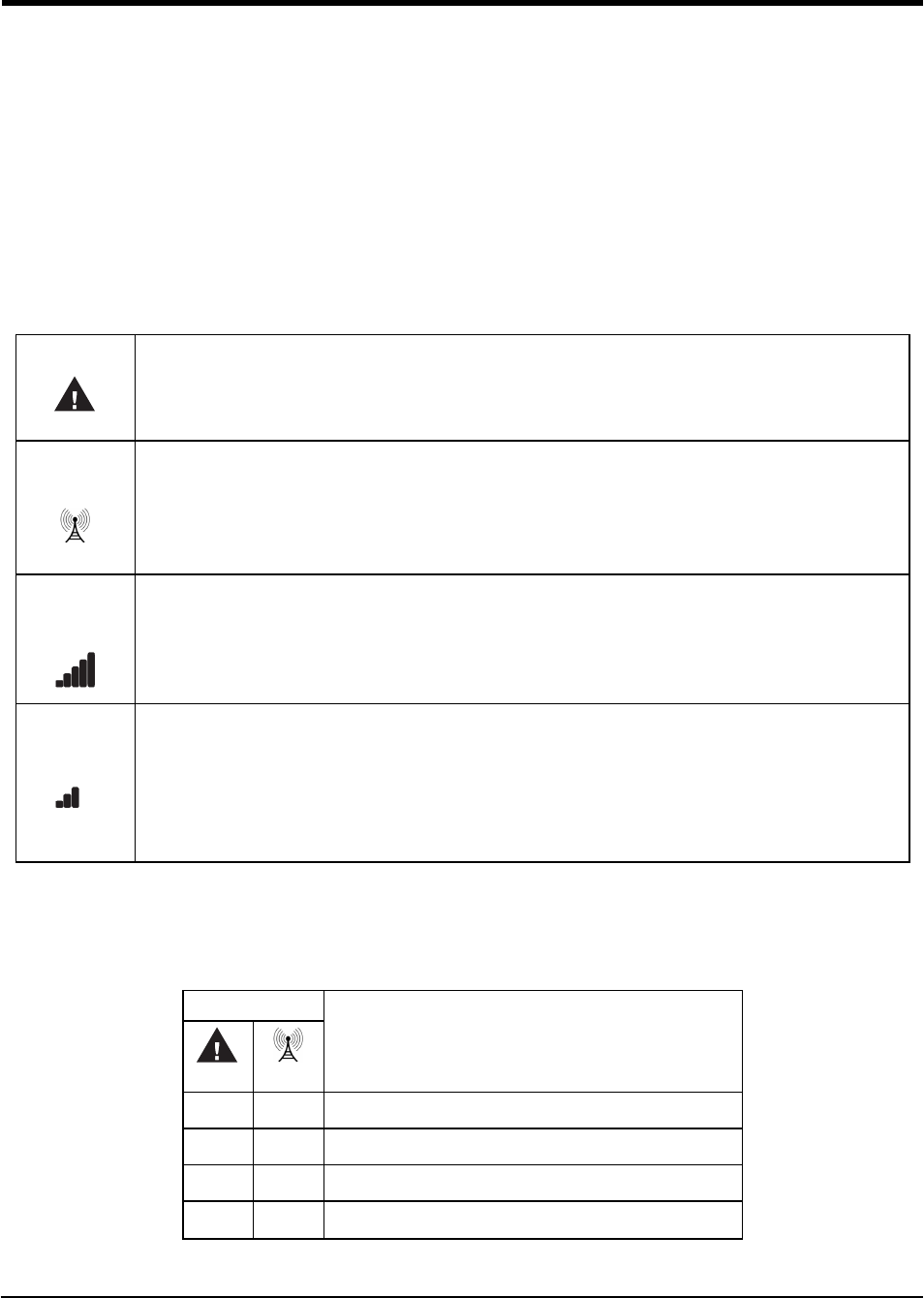
Red
This LED indicates trouble conditions.
On (solid): Trouble Requiring Service
1 Flash: Wireless Network Trouble
2 Flashes: Battery Trouble
3 Flashes: Input Power Trouble
Blue
This LED indicates cellular radio activity. When on (solid), a phone line trouble condition exists. This LED turns on
when the interface switches to the wireless network (due to a landline trouble condition). This LED also flashes once
when the 3G4010/LE4010 transmits a signal and twice when it receives a kiss-off from the central station.
Note: If the 3G4010/LE4010 is programmed to be the primary communicator, the blue LED remains off, but still flashes
during the signal transmission as described above.
Yellow/Green
(Top)
This LED indicates signal strength and network technology. If the 3G4010/LE4010 is operating over a 2G channel (3G
channel for LE4010), the LED is YELLOW. If the 3G4010/LE4010 is operating over a 3G channel (LTE channel for ),
the LED is GREEN. When this LED is On, the reception is optimal. This LED switches On only when the bottom LED
is on.
Yellow/Green
(Bottom)
This LED indicates signal strength and network technology. If the 3G4010/LE4010 is operating in over a 2G channel (3G
channel for LE4010), the LED is YELLOW. If the 3G4010/LE4010 is operating over a 3G channel (LTE channel for
LE4010), the LED is GREEN.
If this LED is Off and the Red LED is On, the Wireless Network service is unavailable (NO SERVICE). This LED
flashes when the Wireless Network reception is poor. If this LED is on, the 3G4010/LE4010 is able to communicate
with the 3G (HSPA) or 2G (GPRS) or LTE (LE4010) network.
5.1.2 Service Mode
To view detailed trouble information on the status LEDs, the 3G4010/LE4010 must be placed in Service
Mode by removing the front cover. When in Service Mode, the status LEDs indicate the trouble condition as
follows.
Number of Flashes
Trouble Type
RED BLUE
1 OFF Wireless network trouble - unable to connect to cellular network
2 OFF Battery trouble - battery with low voltage output
3 OFF Input power trouble
1 Flashing Insufficient signal strength - poor location
3G4010/LE4010 Installation Manual

13
5.1.2 Service Mode
2 Flashing C24 suppressed trouble
3 Flashing C24 communication configuration trouble
1 ON Radio/SIM trouble - radio or SIM unresponsive
2 ON Receiver not available trouble
3 ON Supervision trouble
4 ON Cover tamper is open
OFF - No trouble

14
Section 6: Operating Principles
6.1 Simulated Landline Mode
The simulated landline provides the alarm control panel (with dialer interface) with a backup line in the event
of PSTN line trouble.
Note: The 3G4010/LE4010 must be programmed as a backup communicator for Simulated Landline mode to
operate.
If the voltage on the landline terminals (TIP/RNG) drops below 2.8V for a period of between 10 and 45
seconds - depending on the alarm control panel connected to the T1/R1 terminals- the 3G4010/LE4010
switches the connected telephone device to the cellular network. After waiting between 30 and 40 seconds, it
checks the landline for one of the following:
lIf the landline has been restored, the 3G4010/LE4010 switches the connected device back to the land-
line, OR
lIf the landline is still down, the 3G4010/LE4010 continues the simulation until the landline is restored.
The 3G4010/LE4010 will not switch during ongoing calls.
Note: When the landline is down, the 3G4010/LE4010 provides a dial tone to any device connected to T1
and R1, including any telephones on the premises. The phones on the premises are not, however, able to dial
out over the 3G4010/LE4010.
6.2 Panel Transmission Monitoring (PTM)
The 3G4010/LE4010 can also monitor the panel’s attempt to communicate with the central station. If it determ-
ines that the panel is having difficulty, it switches the line to the cellular network. This feature is only active
when the 3G4010/LE4010 is configured as a backup communicator. This feature is in addition to the regular
line voltage detection.
The 3G4010/LE4010 monitors the phone line for four consecutive failed attempts within a 12-minute window.
A failed attempt is assumed to have occurred when a line seizure takes place during dialing (either the alarm
panel or the customer telephone), but no 1400Hz tone (Contact ID kiss-off) or 2025Hz tone (SIA kiss-off) is
sent from the receiver.
Once the conditions for a failed attempt are met, the 3G4010/LE4010 connects the panel to the cellular net-
work to communicate the events. When the 3G4010/LE4010 switches the line it stays in this mode until the
panel hangs up. On the next event the 3G4010/LE4010 restarts the error detection sequence before switching.
The 3G4010/LE4010 performs this sequence on any phone number that is detected on the line. Specific central
station phone numbers can be programmed into the 3G4010/LE4010 if desired. Up to four, 20-digit numbers
can be added to your profile at Connect 24. If programmed, the 3G4010/LE4010 only looks for a Contact ID
or SIA kiss-off after these numbers are dialed. A Telephone Line Monitoring trouble (PGM output activation
and/or reporting code if applicable) is also activated and/or transmitted when the PTM is activated. A restoral
is sent at the end of the call.
6.3 Cellular Communications Sequence
When an alarm is triggered:
lThe control panel goes off-hook.
lThe 3G4010/LE4010 asserts a dial tone.
lThe control panel dials the number of the central station. Ensure that the alarm panel inserts a minimum
one second pause, or has Dial Tone Search enabled before dialing the number.
lThe 3G4010/LE4010 detects the DTMF dialing and stops dial tone.
Note: The 3G4010/LE4010 is unable to decode pulse dialing.
If the panel is programmed for Contact ID format:
3G4010/LE4010 Installation Manual

15
6.4 Inputs
lThe 3G4010/LE4010 sends the required Contact ID dual-tone handshake to the panel.
lAfter receiving the handshake, the control panel transmits an alarm message in Contact ID format.
lThe 3G4010/LE4010 decodes and transforms the Contact ID digits into an IP packet and sends it to the
central station receiver over the cellular network.
lThe central station receiver acknowledges the alarm and sends a command to the 3G4010/LE4010 to
generate the corresponding 1400Hz Kiss-off signal for a minimum of 800 milliseconds.
After the 3G4010/LE4010 generates a Kiss-off signal, it sends the next alarm or, if no further alarms need to be
sent, the control panel goes on-hook.
If the panel is programmed for SIA (300 baud) format:
lThe 3G4010/LE4010 sends the required SIA handshake to the panel.
lAfter receiving the handshake, the control panel transmits an alarm message in the SIA format.
lThe 3G4010/LE4010 decodes and transforms the SIA events into an IP packet that it sends to the cent-
ral station receiver over the cellular network.
lThe central station’s receiver acknowledges the alarm and sends a command to the 3G4010/LE4010 to
generate the corresponding 2025Hz kiss-off signal for a minimum of one second.
lAfter the 3G4010/LE4010 generates a kiss-off signal, it sends the next alarm or, if no further alarms
need to be sent, the control panel goes on hook.
Note: The 3G4010/LE4010 automatically adjusts the order of the handshakes based on the last format the con-
trol panel used to transmit an event.
6.4 Inputs
The 3G4010/LE4010 has four inputs that can be used to trigger specific communications. These events trans-
mit using the Contact ID or SIA format with Inputs 1-4 reporting as [991] to [994] respectively.
Default settings are:
INPUT 1- FIRE INPUT 3 - BURGLARY
INPUT 2 - PANIC ALARM INPUT 4 - SYSTEM TROUBLE
Inputs can be configured as follows:
Normally Open - input activates when a short condition is detected between the terminal and COM
Normally Closed - input activates when an open condition is detected between the terminal and COM
Single End of Line - input activates when a short or open condition is detected between the terminal and
COM and restores when a 5.6Kohm resistor is detected between the terminal and COM.
Note: These inputs are programmable to communicate using either the Contact ID or SIA format.
Note: For UL/ULC installations, connections between alarm panel outputs and 3G4010/LE4010 inputs must
be run in protective mechanical conduits. To reduce interference with the antenna, do not connect metal con-
duit to the knock-outs in the top of the cabinet.
6.5 Outputs
The 3G4010/LE4010 has four programmable outputs to activate in response to the associated events. Refer to
the 3G4010/LE4010 Wiring Diagram at the back of this manual.
6.5.1 Activating the Outputs
The 3G4010/LE4010 has four open collector outputs capable of a maximum of 50mA. Internal events on the
3G4010/LE4010 can trigger the outputs to turn on an LED or activate an input on the host panel. The default
settings are as follows.
OUTPUT 1: Landline Trouble - Output is normally high and switchs to ground when the telephone line is
down.
OUTPUT 2: Cellular Module or Network Trouble - Output is normally high and switches to ground when
the 3G4010/LE4010 cannot communicate with the network.

16
OUTPUT 3: Power Supply or Battery Trouble - Output is normally high and switches to ground when a
problem with the power source is detected.
OUTPUT 4: General Module Trouble - Output is normally low and switches to high when a Cellular Net-
work Trouble, Power Supply/Battery Trouble, and/or a Failure to Communicate (FTC) trouble is detected.
Note: PGM4 must be connected to the control panel as shown in Figure 4 (Residential applications) or Figures
8-9 (Commercial applications). Program the control panel input Zone/Point as 24hr ‘Supervisory’ with keypad-
only notification when activated. Output 4 on the 3G4010/LE4010 must be set as ‘Active High’.
Note: Once an output has been activated automatically, it will not restore until all the causes of activation are
cleared.
6.6 Reporting Codes
3G4010/LE4010 Reporting Codes CID SIA Programmable Comments
Zone 1 Activation E11A 991 FA 991 YES Delayed 24 Hour Fire *
Zone 1 Restoral R11A 991 FH 991 YES Delayed 24 Hour Fire Restore *
Zone 2 Activation E12A 992 PA 992 YES Panic Alarm *
Zone 2 Restoral R12A 992 PH 992 YES Panic Alarm Restore*
Zone 3 Activation E13A 993 BA 993 YES Burglary *
Zone 3 Restoral R13A 993 BH 993 YES Burglary Restore *
Zone 4 Activation E3AA 994 YX 994 YES System Trouble *
Zone 4 Restoral R3AA 994 YZ 994 YES System Trouble Restore *
PSTN Line Down E351 000 LT 000 FIXED Telco 1 Fault
PSTN Line Restoral R351 000 LR 000 FIXED Telco 1 Fault Restore
Input Loss E337 000 YP 000 FIXED Power Supply Trouble
Input Restoral R337 000 YQ 000 FIXED Power Supply Trouble Restore
Low Battery Alert E338 000 YT 000 FIXED Transmitter Battery Trouble
Low Battery Restoral R338 000 YR 000 FIXED Transmitter Battery Restore
Periodic Test E603 XXX RP XXX FIXED Test Transmission <Receiver Path>
Periodic Test with Trouble E608 XXX RY XXX FIXED Test Transmission <Receiver Path>
Radio Activation R552 000 RS 000 FIXED Remote Programming Successful
Internal Buffer Full E624 000 JL 000 FIXED
FTC Restoral R354 000 YK 000 FIXED Communications Restored
Firmware Update Successful R901 000 LS 000 FIXED
Firmware Update Fail E902 000 LU 000 FIXED
Firmware Update Begin E901 000 LB 000 FIXED
System Tamper E145 000 ES 000 FIXED Expansion Module Tamper
System Tamper Restore R145 000 EJ 000 FIXED Expansion Module Tamper Restore
* C24 Communications default value
6.7 Swinger Shutdown
To prevent "runaway" signals to the central station, the 3G4010/LE4010 is equipped with Swinger Shutdown
which limits certain trouble events to a maximum of four reports every 24 hours. The condition restores and
the counter resets at midnight. Swinger Shutdown applies to the following trouble conditions:
3G4010/LE4010 Installation Manual
17
6.8 Hardware Default
lSystem Tamper/Restore
lLow Battery Trouble/Restore
lTLM Trouble/Restore
lInput Power Trouble/Restore
lFTC Restore
6.8 Hardware Default
A hardware default updates the unit with the latest configuration from C24 Communications if:
lThe device was originally programmed incorrectly.
lThe unit was installed at a different location and then relocated to a new site.
lA SIM card is being swapped.
To perform a hardware default, follow these steps:
1. Power down the unit (remove primary DC power and remove the backup battery) and remove all con-
nections to Zone1, Zone 2, PGM1 and PGM.
2. Connect a wire between Z2 (terminal 14) and PGM2 (terminal 8)or Z1 (terminal 13) and PGM1 (ter-
minal 7).
3. Power up the radio by connecting the battery (if present) first and then primary DC power.
4. Wait for 20 seconds and then completely power down the unit.
5. Disconnect the wire between the Zone and PGM terminals.
Note: Failure to perform hardware default will result in the unit transmitting with the previously programmed
configuration.
6.9 Communicator Reset/Update
The firmware of the device can be updated over Cellular or PC-Link:
lWhen the firmware update begins, all LED are ON.
RED BLUE
Yellow/Green
(Top)
Yellow/Green
(Bottom)
ON ON ON ON
lDuring the firmware update process the LEDs are cycled individually in a chaser pattern. (different from
the Advanced Carrier Selection pattern).
RED BLUE Yellow/Green
(Top)
Yellow/Green
(Bottom)
FLASH ON OFF OFF OFF
OFF FLASH ON OFF OFF
OFF OFF FLASH ON OFF
OFF OFF OFF FLASH ON
FLASH ON OFF OFF OFF
OFF FLASH ON OFF OFF
OFF OFF FLASH ON OFF
OFF OFF OFF FLASH ON
lAfter a successful update, the unit automatically restarts.
Note: Several resets take place during a single Firmware update session.

18
Note: The unit re-requests programming after a firmware update; the version number is updated and viewable
via C24 Communications.
Note: Unit must not be powered down during a Firmware update.
Note: Unit does not process remote firmware update requests if any of the following troubles is present. If the
trouble occurs after the unit has processed the firmware update request, the firmware update is not interrupted.
• Input Power Trouble
• Low Battery Trouble
6.10 Low Power Radio Shutdown
When the battery voltage reaches the low battery threshold of 10.5V, the unit turns off the radio to prevent
unnecessary network registrations. In this state, the unit does not communicate any events.
Radio shutdown is indicated by the LEDs as follows:
lRed LED indicates low battery trouble.
lTwo green LEDs blinking on/off together indicates the radio is not ready.
This LED sequence is displayed until the low battery voltage is restored and the radio is enabled again.
6.11 SMS Command and Control
The user can remotely arm/disarm their security panel and control PGM outputs via SMS commands.
6.11.1 Arming/Disarming the Security Panel
1. Program a PGM output to Remote Arming in C24 Communications.
2. Ensure this PGM output is connected to a relay to the security panel zone.
3. Set up the zone on the security panel as momentary or maintained arming.
lIf the security panel uses momentary key switching, configure the communicator PGM with a
time field of 05. In this configuration, both arm and disarm generate the pulse.
lIf the security Panel uses maintained key arming, configure the communicator PGM with a time
field of 00.
4. Optionally, the panel arm state can be configured for the communicator to detect by setting a panel
PGM output to reflect panel arm state and having a relay connected to a communicator zone configured
to follow panel arm state.
6.11.2 Remote Control of PGM
1. Set up one or more PGM outputs to Remote Control PGM configuration. A PGM can be latched or
timed:
lsetting the PGM timer to 00 causes it to be latched. The PGM will not turn off unless the turn
off command is received.
lsetting the PGM timer to a value between 1 and 255 seconds causes it to be timed. The PGM
activates for the programmed duration.
2. Via C24 Communications, program the phone number and access code used for SMS command and con-
trol.
lUp to 6 different phone numbers can be programmed to perform SMS command and control.
lThe password can be 4 to 8 alphanumeric characters and is not case sensitive.
The SMS command and control can be sent in the following format:
For arming/disarming the Security Panel
Arm <access code>, example Arm 12345678
For activating/deactivating a specific PGM
Activate <PGM #> <access code>, Activate 1 12345678
3G4010/LE4010 Installation Manual
19
6.12 Phone Number Call Direction
The following SMS command and control operations are available:
Arming
Language Command Label (must not be case sensitive)
English Arm
French Armement
Spanish Armado
Disarming
Language Command Label (must not be case sensitive)
English Disarm
French Desarmement
Spanish Desarmado
Activate PGM
Language Command Label (must not be case sensitive)
English Activate
French Activation
Spanish Activar
Deactivate PGM
Language Command Label (must not be case sensitive)
English Deactivate
French Desactivation
Spanish Desactivar
Status Request
Language Command Label (must not be case sensitive)
English Status Request
French Etat Démandé
Spanish Petición de Estado
Invalid command is sent when no zones are programmed to read security arm status.
Help
Language Command Label (must not be case sensitive)
English Help
French Aide
Spanish Ayuda
Help displays all available commands for the selected language.
6.12 Phone Number Call Direction
The user has the ability to program the PTM phone numbers to receiver group 1 or receiver 2.

20
The number programmed in the communicator must also be programmed as the panel phone number. When the
communicator detects the phone number, it communicates to the receivers of the corresponding group.
Note: If no PTM phone number is programmed, all panel calls go to Receiver Group 1.
6.13 C24 Communications Remote Programming
The inputs, outputs, and other features of the 3G4010/LE4010 can be remotely programmed through the C24
Communications website for fast and convenient installation using the Internet.
Note: This programming option has not been investigated by UL.
3G4010/LE4010 Installation Manual
21
Section 7: Troubleshooting Guide
Section 7: Troubleshooting Guide
Powering up the 3G4010/LE4010 – When powering up the 3G4010/LE4010, always connect the battery (if
used)first before connecting primary DC power from the control panel or transformer.
Wiring Primary – R-1/T-1 of 3G4010/LE4010 to RING/TIP of control panel, DC power from control panel or
DC transformer to DC input, backup battery.
Wiring Backup – Incoming line to RING/TIP on 3G4010/LE4010, R-1/T-1 of 3G4010/LE4010 to RING/TIP
of control panel, R-1/T-1 of control panel to house phones, DC power from control panel or DC transformer to
DC input, backup battery.
Testing Communications – When the 3G4010/LE4010 transmits a signal for the control panel, or for an
internal transmission, the BLUE light flashes once when the signal is transmitted and twice when it receives a
kiss-off.
SIM – The SIM should be activated at least 24 hours prior to installation. The 3G4010/LE4010 will show sig-
nal strength with an inactive SIM; However, it will display the signal strength of any available wireless net-
work. The SIM must be active to ensure the signal strength displayed is that of the wireless network provider
for which the SIM belongs to.
Panel Programming – The control panel should be programmed to communicate Contact ID or SIA exactly
the same way it would be programmed to communicate Contact ID or SIA over the telephone line.
Green/Yellow
LED Status
What it
means: CSQ Values Signal Strength Status
Both Signal Strength LEDs
ON
Excellent Sig-
nal Strength 14+ lUnit can be installed in the current mounting location.
Top LED FLASHING
with bottom LED ON
Excellent Sig-
nal Strength 11-13 lUnit can be installed in the current mounting location.
Bottom LED ON Good Signal
Strength 7-10 lUnit can be installed in the current mounting location.
Bottom LED FLASHING Poor Signal
Strength
5-6
(no trouble)
1-4
(with trouble)
lEnsure the antenna cable is plugged securely into the radio con-
nector.
lIf the SIM is active, connect a battery to the unit and test vari-
ous locations for good/excellent signal strength.
lConnect an antenna extension kit (LTE-8ANT, LTE-15ANT,
LTE-25ANT, LTE-50ANT).
Both LEDs OFF No Signal
Strength 0
lIf the red LED is also FLASHING, refer to the RED LED
chart.
lVerify SIM card is activated.
lEnsure the antenna cable is plugged securely into the radio con-
nector.
lIf the SIM is active, connect a battery to the unit and test vari-
ous locations for good/excellent signal strength.
lConnect an antenna extension kit (LTE-8ANT, LTE-15ANT,
LTE-25ANT, LTE-50ANT).
Both LEDs Flashing
ON/OFF together
Signal Strength
is invalid N/A Radio is in process of network registration.
Both LEDs Alternating Radio Reset
Sequence N/A Radio is performing a Reset. If the issue persists, please verify the SIM
card is inserted correctly.

22
# of
Flashes Trouble Type
Trouble Notes
Red Blue
On On No Signal Strength
lVerify SIM card is activated.
lEnsure the antenna cable is plugged securely into the radio connector.
lIf the SIM is active, connect a battery to the unit and test various locations for
good/excellent signal strength.
lConnect an antenna extension kit (LTE-8ANT, LTE-15ANT, LTE-25ANT, LTE-
50ANT).
1 Off Wireless Network Trouble
lEnsure the SIM card has been activated.
lThe antenna cable should be plugged securely into the radio connector.
lEnsure there is good signal strength (at least one green light ON).
lVerify the installation area is not experiencing a network outage.
2 Off Battery Trouble
lIf a battery is not used in the installation, ensure that the "Internal Battery Con-
nected" is not selected in C24 Communications.
lIf a battery is used in the installation, verify the battery is connected properly
lMeasure the battery under load and verify it is charged to at least 12.5VDC. If not,
wait at least 1 hour for the battery to charge.
lRemove the battery and measure the voltage; the voltage should be at least 12VDC.
lVerify the input DC supply is rated at 13.8VDC @ 180mA minimum.
lReplace battery
3 Off Input Power Trouble
lEnsure the power source connected to the 3G4010/LE4010 is providing 13.8VDC
@ 180mA.
1 Flash Insufficient Signal Strength
lEnsure the antenna cable is plugged securely into the radio connector.
lIf the SIM is active, connect a battery to the unit and test various locations for
good/excellent signal strength.
lConnect an antenna extension kit (LTE-8ANT, LTE-15ANT, LTE-25ANT, LTE-
50ANT)
2 Flash Not Used
3 Flash C24 Communications Con-
figurations Trouble
lEnsure the SIM card is activated and correctly initialized through C24 Com-
munications.
1 On Radio/SIM Trouble
lEnsure the SIM Card is inserted correctly and firmly.
lEnsure the antenna cable is plugged securely into the radio connector.
2 On Receiver Not Available
Trouble
lContact the monitoring station to verify that the 3G4010/LE4010 programming is
correct (port, IP address, DNIS).
lContact your central station to verify they are not experiencing any receiver issues.
3 On Supervision Trouble lContact your central station to verify they are not experiencing any receiver issues.
4 On Tamper Trouble lEnsure the front cover is secured and the case tamper is closed.
The Red light will flash to indicate various trouble conditions outlined previously. If multiple trouble con-
ditions are present, the red light will flash according to the highest priority trouble. For example, if both a
3G4010/LE4010 wireless network trouble (one flash) and a low battery trouble (two flashes) are present; the
red light will flash one time. Once the 3G4010/LE4010 wireless network trouble condition is corrected, the
red light will then begin flashing two times.
3G4010/LE4010 Installation Manual
23
Section 7: Troubleshooting Guide
General Troubles With Your System
The control panel is displaying a
telephone line trouble condition
lEnsure T1 and R1 of the 3G4010/LE4010 are wired to the TIP and RING terminals of the
control panel.
lIf the 3G4010/LE4010 is being used as the primary communicator, the blue light will always
be OFF.
lIf the 3G4010/LE4010 red light is FLASHING, refer to the troubleshooting chart in this
guide.
The control panel displays a com-
munication trouble condition
lEnsure the panel is programmed for Contact ID or SIA.
lEnsure the control panel does not indicate a TLM trouble condition.
lIf the 3G4010/LE4010 red light is FLASHING refer to the troubleshooting chart in this
guide.
No signals are received at the cent-
ral station but no trouble condition
is displayed
lEnsure the control panel has a central station phone number programmed.
lEnsure the control panel has the correct account number programmed.
lVerify the reporting codes are programmed or the auto Contact ID option is enabled.
lEnsure the control panel communicator is enabled.
lConnect a handset to T1 and R1 of the 3G4010/LE4010 in monitor mode to verify the control
panel is trying to communicate.
Not receiving internal signals gen-
erated directly from the
3G4010/LE4010
lEnsure the 3G4010/LE4010 was initialized with the correct account number. This can be
checked by logging into the C24 Communications website.
lEnsure that no trouble conditions are present on the 3G4010/LE4010.
The phone line is seized when the
3G4010/LE4010 is connected
lVerify correct phone line wiring.
lEnsure the Ringer Equivalency Number (REN) is not being exceeded on the line.
General Information
Removing/Connecting the antenna
lTo remove the antenna from the 3G4010/LE4010, place your thumb on the end of the con-
nector at the modem, then place a screwdriver between the modem and connector. Gently
turn the screwdriver away to ‘pop’ out the connector from the modem.
lTo install the antenna, firmly push the connector into the modem until it ‘snaps’ into place.
Enrolling a 3G4010/LE4010
lThe 3G4010/LE4010 can be enrolled by going through the GVRU voice prompt, and com-
pleting the activation of the SIM card, and the initialization of the 3G4010/LE4010.
lThe 3G4010/LE4010 can also be enrolled using the C24 Communications website (www.-
connect24.com) or the C24 Communications mobile site (m.connect24.com).
SIM card activation period
lA SIM card can take up to 24 hours to be activated by the provider. However, it typically
takes less than an hour for the SIM card to be activated.
Checking SIM status
lGo to www.connect24.com and login. A search can be performed for a specific account and
its current status
lSIM status can also be checked through the GVRU.
Critical Shutdown on
3G4010/LE4010 backup battery
(with no DC input applied)
lIf the 3G4010/LE4010 backup battery is used and is below 10.5VDC, the unit will go into crit-
ical shutdown.
lThe critical shutdown state will be displayed by the red light flashing followed by the blue
and two green lights flashing.
lThe lights will continue to flash in this sequence until the battery is charged above 12.4VDC.

24
Swinger Shutdown for
3G4010/LE4010 Troubles
lTrouble events can send a maximum of 4 troubles and restorals per day.
lSwinger Shutdown only affects signal transmissions, not the functionality of the
3G4010/LE4010 lights or PGM outputs.
lSwinger shutdown is reset at midnight or upon a full power cycle of the 3G4010/LE4010.
Test this product at least once a year.
3G4010/LE4010 Installation Manual
25
7.1 LE4010 IM Wiring Diagrams
7.1 LE4010 IM Wiring Diagrams
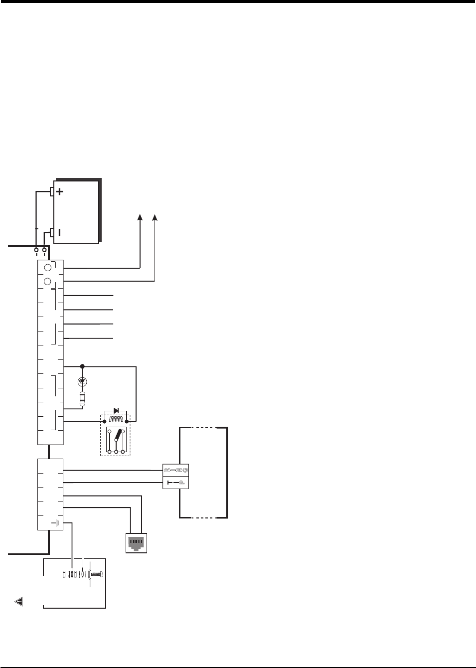
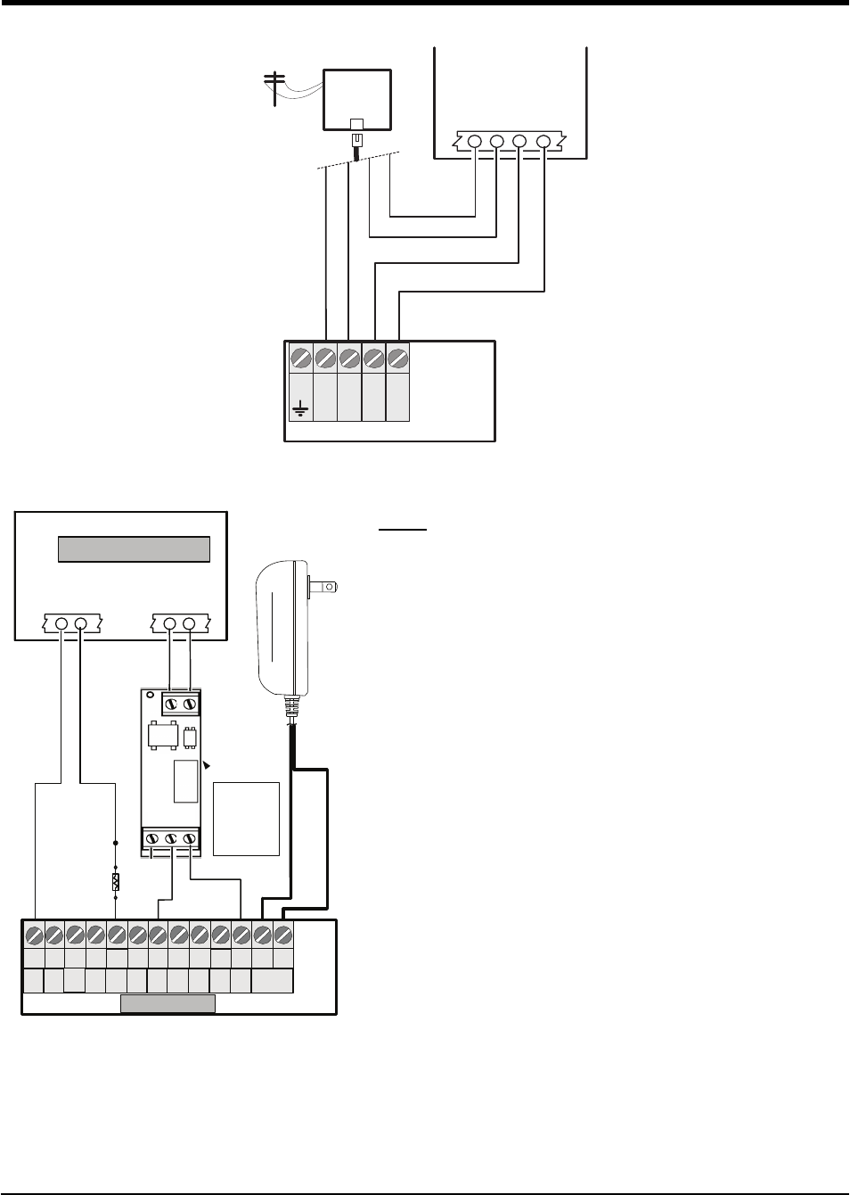
Figure 10-1 Wiring Diagram
5
41 23 6 7 8 9 10 11 14 15 16 17
LE
LI O1O2 O3 O4
+OC
13
12
AS
L1 L2 L3 L4
1K5
T
I
P
R
I
N
G
32
DC INAUX
2 31
COM
41
COMT1 R1TIPRING
4
PGM ZONE
+
-
RJ-45
BATTERY
Sealed Rechargeable
12V / 1.2Ah
Typical battery charge: 30-50 mA
Recommended Model: 12V/1.2Ah
Battery not required
if CON5 is set to NO BAT
9-14VDC/ 700mA (max)
Earth-ground
Ground wire from
building electrical
installation
Inputs to be connected
to dry contact outputs
from alarm control panel
with 5.6KΩ EOL resistors
}
GROUND
CONNECTION
Tighten nut to break paint &
make good connection to
the cabinet.
Nut
Nut
Bolt
Lock washer
Lock washer
Star washer
Cabinet
Alarm Control Panel with
Dialler Interface
(Supports Contact ID and
SIA formats)
Panel Aux Power or
External Power Supply
Telephone Line
Connection
Supervision
Relay
RM1-UL Installations
RM1C-ULC Installations
Connect relay contacts to
a zone input on the alarm
control panel for communicator
troubles supervision
(24hr-type zone)
Optional
use of PGM
output (See
Programming)
WARNING!
HIGH VOLTAGE. DISCONNECT AC
POWER & TELEPHONE LINES
PRIOR TO SERVICING
WARNING: Incorrect connections may result in PTC failure or improper operation. Inspect wiring and ensure connections are correct before turning on.
All circuits are classied for UL installations as Power Limited/Class II Power Limited except for the battery leads which are not Power Limited. Do not route any wiring over circuit
boards. Maintain at least 1” (25.4mm) separation. A minimum 1/4” (6.4mm) separation must be maintained at all points between Power Limited wiring and all other Non-Power
Limited wiring. Route wires as indicated in the diagram.
For UL Installations, the system shall be installed in accordance with chapter 2 of the ANSI/NFPA 72 and ANSI/NFPA70. Recommended locations and wiring methods shall be in
accordance with the National Electrical Code, ANSI/NFPA 70, the Standard for Installation and Classication of Burglar and Holdup Alarm Systems, UL 681, and the Standard for
Central-Station Alarm Services, UL 827.
For ULC Installations, the recommended locations and wiring methods shall be in accordance with CSA C22.1, Canadian Electrical Code, Part I, Safety Standard for Electrical Installa-
tions; CAN/ULC-S302, Installation and Classication of Burglar Alarm Systems for Financial and Commercial Premises, Safes and Vaults; and CAN/ULC-S301, Standard for Central and
Monitoring Station Burglar Alarm Systems and the Standard for the Installation of Residential Fire Warning Systems, CAN/ULC-S540. Do not install the equipment in places where the
signal strength does not meet the minium recommended signal strength level. Do not run zone inputs and T1/R1 wiring along AC wires or other circuits with high frequency signals
in order to reduce possibility of interference and false alarms.
(Use No. 26 AWG wires for
the connection to PSTN)
For ULC Fire Monitoring installations re alarm signals shall be sent
simultaneously over POTS line (using the dialler) and over the
wireless network (using 3G4010/LE4010). Connect alarm output
from control panel (PGM) to the input on the communicator that is
programmed as a Fire Alarm Input.
Examples of Control Units/Subscribers Units or Power Supplies
compatible models: DSC PC1864, PC1832, PC1616, PC5204, etc.
This connection
is necessary
26
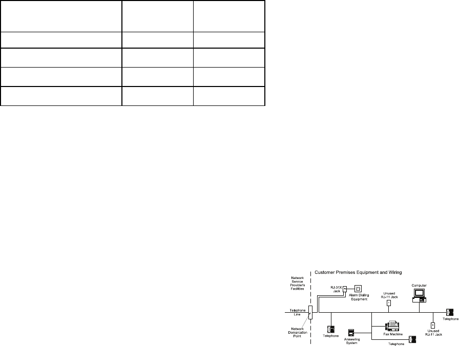
Figure 10-2 Telephone Connection
RED (R)
GREEN (T)
GRAY (R)
BROWN (T)
RJ-31X
RING
TIP
CONTROL PANEL
Incoming
Phone line
Handset
RI
TI
T1
R1
TIP
RING
4
321 5
Communicator
TIP T1 R1
RING
Figure 10-3 Power Supply and Supervision Wiring Diagram
(BLK/WHT) +13.8VDC
(BLK ) GND
Control
Panel
EOL
Resistor
See Note 3
DSC
RM-2
RELAY
NC
C
NO
ZONE
TERMINALS
(See Note 1)
- +
+12VDC
GND
CONTROL PANEL
Aux Power
+ -
DSC
Supervision
Relay
See Note 2
17
16
151412 18
13
11
1097 86
19
Z4
Z3Z2
COM 20
Z1
AUX
+
PGM
3
PGM
1
PGM
4
COM
Communicator
PGM
3
DC IN
+ -
Power Adaptor
Notes:
1. Program the zone/point as “Supervisory” type with keypad-
only announciation when in alarm. Do NOT use a zone/point
that is normally used for 2-wire smoke detectors.
2. The power supervision relay (RM-2) is only used when the
3G4010/LE4010 is not powered by the control panel. The
relay is not required since a loss of input power will generate
a signal to the CMC.
3. Output 4 on the 3G4010/LE4010 must be set as “Active
High” (default).
4. This equipment has no mains on/off switch. The plug of the
direct plug-in power supply is intended to serve as the dis-
connecting method if the equipment must be quickly dis-
connected. Ensure that access to the mains plug and
associated mains socket/outlet is never obstructed.
3G4010/LE4010 Installation Manual

27
7.1 LE4010 IM Wiring Diagrams
The following wiring diagrams are examples of ULC Listed Fire Monitoring Installation connections.
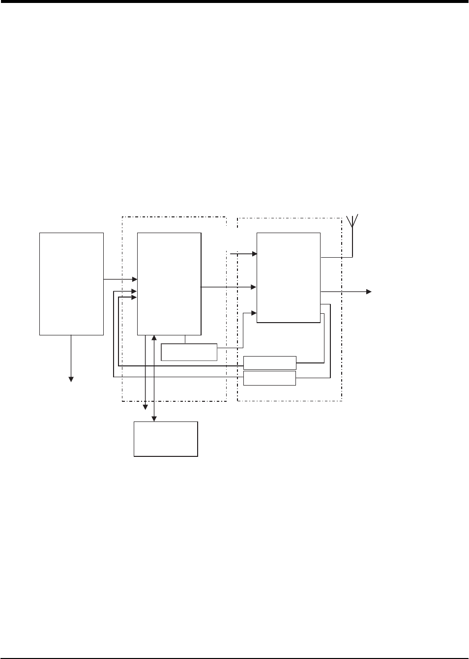
Figure 10-4 Wiring Diagram for Fire Alarm Control Unit (with dialler) and Cellular Transmitter (Passive Com-
munication System)
AUX Power
(12V/700mA)
RM1C ULC
Relay
Fire Alarm
Control Unit
TIP/RING
Zone Input
Outputs
Fire
Trouble
3G Cellular
Transmitter
3G4010
T1/R1
TIP/RING
Zone PGM4
Inputs Output
3G4010 cabinet
3G (HSPA) or
2G (GPRS)
AC Input
PSTN
Notes:
lPower for the 3G4010/LE4010 shall be provided from the Fire Alarm Control Unit or separately listed
power supply rated for the application (12V/700mA).
lAll wiring connections must be run in a protective conduit.
lFor local supervision of the wireless transmitter, connect PGM output from 3G4010/LE4010 to one
zone input on the Fire Alarm Control Unit.
lDry Contact Trouble output from ULC Listed Fire Alarm Control Unit must be connected to zone input
on the 3G4010/LE4010 for supervison of Tip/Ring connection.
lFire Alarms must be sent over both communication channels. Fire output from Fire Alarm Control Unit
must be connected to input 1 on the 3G4010/LE4010.
l24 hour Test Transmission must be enabled on the dialler and on the 3G4010/LE4010.
Figure 10-5 DSC Subscribers’ Unit Fire and Cellular Transmitter Mounted in the Same Room
DSC
Subscribers’
Unit Fire
Zone
Inputs TIP
TIP RING
PGM1
DSC Keypad
LCD4501
PK55XX 3G Cellular
Transmitter
3G4010
T1/R1
TIP/RING
Zone
Input PGM4
AUX Power
12V/700mA
RM1C ULC
Relay
PC5003C
PC4050CR
cabinet
3G (HSPA)/2G (GPRS)
PSTN
AC Input
AC Input
PC4020
PC1864
PC1832
PC1616
RM1C ULC
Relay
3G4010 cabinet
Outputs
Fire
Supervisory
Trouble
Fire Alarm Control Unit
Notes:
lPower for 3G4010/LE4010 must be provided from Fire Alarm Control Unit or separately listed power
supply rated for the application (12V/700mA).
lAll wiring connections must be run in a protective conduit.
lPhone Line Monitoring (TLM) must be enabled.
lPhone Line trouble is indicated by the Blue LED on the 3G4010/LE4010.
28
lConnect PGM4 output from the 3G4010/LE4010 (Trouble Conditions) to a zone input on the Sub-
scriber Unit for supervision of the GSM Transmitter.
l24hour Test Transmission over phone line (PSTN) and 3G4010/LE4010 must be enabled.
lFire Alarm smust be sent over both communication channels.
lOn the Subscribers’ Unit, program PGM1 for PC1616/PC1832/PC1864 as System Event (Section [009]
as type 10; Section [501] Fire Event option 2 ON). An alternate option is to program PGM1 as Zone
Follower (Section [009] = 29) and assign Fire Zone to PGM1 in Section [551]. Ensure Bit 3 is on in
[501]. In this case, a restored fire alarm condition does not require the DSC control panel to be reset.
For PC4020, program PGM1 as type 49 Steady Fire ([00070049]).
lDry contact outputs from ULC Listed Fire Alarm Control Unit must be connected to zone inputs on the
ULC Listed DSC subscribers' Unit Fire.
lRefer to detailed diragrms.
Figure 10-6 DSC Subscribers’ Unit Fire and 3G Cellular Transmitter Mounted Remotely
Alternate Wiring Diagram for DSC Subscribers' Unit Fire and Cellular Transmitter Passive Communication Sys-
tem - Using Phone Line Supervision Relay
Fire Alarm
Control Unit
Outputs
Fire
Supervisory
Trouble
DSC
Subscribers’
Unit Fire
Zone
Inputs
TIP
RING
PGM1
DSC Keypad
LCD4501
PK55XX
3G Cellular
Transmitter
3G4010
T1/R1
PGM1
TIP/RING
Zone
Input PGM4
AUX Power
12V/700mA
RM1C ULC
Relay
PC5003C
PC4050CR
cabinet
3G (HSPA)/2G (GPRS)
PSTN
AC Input
AC Input
PC4020
PC1864
PC1832
PC1616
RM1C ULC
Relay
GS4010 cabinet
RM1C ULC
Relay
PLEASE NOTE THAT EITHER RM1C ULC OR RM2 RELAYS CAN BE USED FOR ULC
INSTALLATIONS
Notes:
lConnect PGM output from the 3G4010/LE4010 (Phone Line Trouble) to a zone input on the subscriber
unit for supervision of the phone line voltage.
lWhen the 3G4010/LE4010 is installed remotely from the DSC Control Panel, the Phone Line Trouble
condition must be monitored at the keypad using an additional RM1C relay.
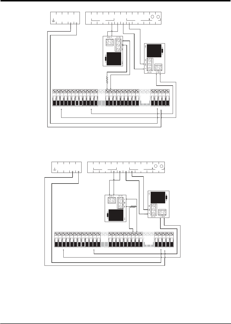
Figure 10-7 Connection Details for Cellular Network Supervision Relay and Redundant Fire Alarm Trans-
mission
3G4010/LE4010 Installation Manual
29
7.1 LE4010 IM Wiring Diagrams
5.6 KOhm
Cellular Network
Supervision
Relay
Redundant
Fire Alarm
Initiation
5
41 23 6 7 8 9 10 11 14 15 16 17 18
LE
LI O1 O2 O3 O4
+OC
13
12
AS
L1 L2 L3 L4
3G4010
AC AC RED BLK YEL GRN Z1 COM Z2 Z3 COM Z4 Z5 COM Z6 Z7 COM Z8
AUX+ BELL+
AUX- BELL-
PGM1 PGM3 EGND TIP T-1
PGM2 PGM4
RING R-1
PC1864
Only
PC1864
PC1832
Only
AC AC RED BLK YEL GRN Z1 COM Z2 Z3 COM Z4 Z5 COM Z6 Z7 COM Z8
AUX+ BELL+
AUX- BELL-
PGM1 PGM3 EGND TIP T-1
PGM2 PGM4
RING R-1
PC1864
Only
PC1864
PC1832
Only
32
DC INAUX
2 31
COM
41
COMT1 R1TIP RING
4
PGM ZONE
+
-
Note: Use EOL resistor in series with N.O. contacts of the relay connected to PGM4.
Figure 10-8 Connection Details for Cellular Network Supervision Relay and Redundant Fire Alarm Trans-
mission
5.6 KOhm
Cellular Network
Supervision
Relay
Redundant
Fire Alarm
Initiation
3G4010
AC AC RED BLK YEL GRN Z1 COM Z2 Z3 COM Z4 Z5 COM Z6 Z7 COM Z8
AUX+ BELL+
AUX- BELL-
PGM1 PGM3 EGND TIP T-1
PGM2 PGM4
RING R-1
PC1864
Only
PC1864
PC1832
Only
AC AC RED BLK YEL GRN Z1 COM Z2 Z3 COM Z4 Z5 COM Z6 Z7 COM Z8
AUX+ BELL+
AUX- BELL-
PGM1 PGM3 EGND TIP T-1
PGM2 PGM4
RING R-1
PC1864
Only
PC1864
PC1832
Only
32
DC INAUX
2 31
COM
41
COMT1 R1TIP RING
4
PGM ZONE
+
-
Note: Use EOL resistor in parallel with N.O. contacts of the relay connected to PGM4.
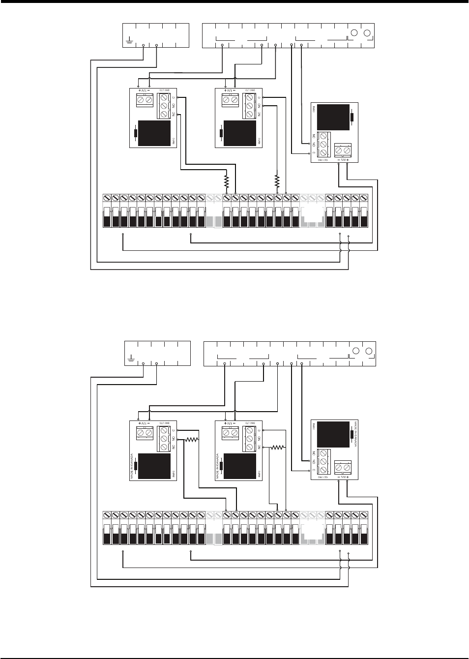
Figure 10-9 Connection Details for GSM Supervision Relay, Phone Line Supervision and Redundant Fire
Alarm Transmission
30
32
DC INAUX
2 31
COM
41
COMT1 R1TIP RING
4
PGM ZONE
+
-
5.6 KOhm
5.6 KOhm
Cellular
Network
Supervision
Relay
Phone Line
Supervision
Relay
Redundant
Fire Alarm
Initiation
3G4010
AC AC RED BLK YEL GRN Z1 COM Z2 Z3 COM Z4 Z5 COM Z6 Z7 COM Z8
AUX+ BELL+
AUX- BELL-
PGM1 PGM3 EGND TIP T-1
PGM2 PGM4
RING R-1
PC1864
Only
PC1864
PC1832
Only
AC AC RED BLK YEL GRN Z1 COM Z2 Z3 COM Z4 Z5 COM Z6 Z7 COM Z8
AUX+ BELL+
AUX- BELL-
PGM1 PGM3 EGND TIP T-1
PGM2 PGM4
RING R-1
PC1864
Only
PC1864
PC1832
Only
Note: Use EOL resistor in series with N.O. contacts of the relay connected to PGM4.
Figure 10-10 Connection Details for Cellular Network Supervision Relay, Phone Line Supercision Relay and
Redundant Fire Alarm Transmission
5.6 KΩ
5.6 KΩ
Cellular
Network
Supervision
Relay
Phone Line
Supervision
Relay
Redundant
Fire Alarm
Initiation
3G4010
AC AC RED BLK YEL GRN Z1 COM Z2 Z3 COM Z4 Z5 COM Z6 Z7 COM Z8
AUX+ BELL+
AUX- BELL-
PGM1 PGM3 EGND TIP T-1
PGM2 PGM4
RING R-1
PC1864
Only
PC1864
PC1832
Only
AC AC RED BLK YEL GRN Z1 COM Z2 Z3 COM Z4 Z5 COM Z6 Z7 COM Z8
AUX+ BELL+
AUX- BELL-
PGM1 PGM3 EGND TIP T-1
PGM2 PGM4
RING R-1
PC1864
Only
PC1864
PC1832
Only
21
COMT1 R1TIP RING
3
DC INAUX
2 31
COM
44
PGM ZONE
+
-
Note: Use EOL resistor in parallel with N.O. contacts of the relay connected to PGM4.
3G4010/LE4010 Installation Manual
EULA
IMPORTANT - READ CAREFULLY: DSC Software purchased with or without
Products and Components is copyrighted and is purchased under the following license
terms:
This End-User License Agreement (“EULA”) is a legal agreement between You (the
company, individual or entity who acquired the Software and any related Hardware)
and Digital Security Controls, a division of Tyco Safety Products Canada Ltd.
(“DSC”), the manufacturer of the integrated security systems and the developer of the
software and any related products or components (“HARDWARE”) which You
acquired.
If the DSC software product (“SOFTWARE PRODUCT” or “SOFTWARE”) is intended
to be accompanied by HARDWARE, and is NOT accompanied by new HARDWARE,
You may not use, copy or install the SOFTWARE PRODUCT. The SOFTWARE
PRODUCT includes computer software, and may include associated media, printed
materials, and “online” or electronic documentation.
Any software provided along with the SOFTWARE PRODUCT that is associated with
a separate end-user license agreement is licensed to You under the terms of that license
agreement.
By installing, copying, downloading, storing, accessing or otherwise using the
SOFTWARE PRODUCT, You agree unconditionally to be bound by the terms of this
EULA, even if this EULA is deemed to be a modification of any previous arrangement
or contract. If You do not agree to the terms of this EULA, DSC is unwilling to
license the SOFTWARE PRODUCT to You, and You have no right to use it.
SOFTWARE PRODUCT LICENSE
The SOFTWARE PRODUCT is protected by copyright laws and international
copyright treaties, as well as other intellectual property laws and treaties. The
SOFTWARE PRODUCT is licensed, not sold.
1. GRANT OF LICENSE This EULA grants You the following rights:
Software Installation and Use - For each license You acquire, You may have only one
copy of the SOFTWARE PRODUCT installed.
Storage/Network Use - The SOFTWARE PRODUCT may not be installed, accessed,
displayed, run, shared or used concurrently on or from different computers, including a
workstation, terminal or other digital electronic device (“Device”). In other words, if
You have several workstations, You will have to acquire a license for each
workstation where the SOFTWARE will be used.
Backup Copy - You may make back-up copies of the SOFTWARE PRODUCT, but
You may only have one copy per license installed at any given time. You may use the
back-up copy solely for archival purposes. Except as expressly provided in this
EULA, You may not otherwise make copies of the SOFTWARE PRODUCT, including
the printed materials accompanying the SOFTWARE.
2. DESCRIPTION OF OTHER RIGHTS AND LIMITATIONS
Limitations on Reverse Engineering, Decompilation and Disassembly - You may
not reverse engineer, decompile, or disassemble the SOFTWARE PRODUCT, except
and only to the extent that such activity is expressly permitted by applicable law
notwithstanding this limitation. You may not make any changes or modifications to
the Software, without the written permission of an officer of DSC. You may not
remove any proprietary notices, marks or labels from the Software Product. You shall
institute reasonable measures to ensure compliance with the terms and conditions of
this EULA.
Separation of Components - The SOFTWARE PRODUCT is licensed as a single
product. Its component parts may not be separated for use on more than one
HARDWARE unit.
Single INTEGRATED PRODUCT - If You acquired this SOFTWARE with
HARDWARE, then the SOFTWARE PRODUCT is licensed with the HARDWARE as
a single integrated product. In this case, the SOFTWARE PRODUCT may only be
used with the HARDWARE as set forth in this EULA.
Rental - You may not rent, lease or lend the SOFTWARE PRODUCT. You may not
make it available to others or post it on a server or web site.
Software Product Transfer - You may transfer all of Your rights under this EULA
only as part of a permanent sale or transfer of the HARDWARE, provided You retain
no copies, You transfer all of the SOFTWARE PRODUCT (including all component
parts, the media and printed materials, any upgrades and this EULA), and provided the
recipient agrees to the terms of this EULA. If the SOFTWARE PRODUCT is an
upgrade, any transfer must also include all prior versions of the SOFTWARE
PRODUCT.
Termination - Without prejudice to any other rights, DSC may terminate this EULA if
You fail to comply with the terms and conditions of this EULA. In such event, You
must destroy all copies of the SOFTWARE PRODUCT and all of its component parts.
Trademarks - This EULA does not grant You any rights in connection with any
trademarks or service marks of DSC or its suppliers.
3. COPYRIGHT
All title and intellectual property rights in and to the SOFTWARE PRODUCT
(including but not limited to any images, photographs, and text incorporated into the
SOFTWARE PRODUCT), the accompanying printed materials, and any copies of the
SOFTWARE PRODUCT, are owned by DSC or its suppliers. You may not copy the
printed materials accompanying the SOFTWARE PRODUCT. All title and intellectual
property rights in and to the content which may be accessed through use of the
SOFTWARE PRODUCT are the property of the respective content owner and may be
protected by applicable copyright or other intellectual property laws and treaties. This
EULA grants You no rights to use such content. All rights not expressly granted
under this EULA are reserved by DSC and its suppliers.
EXPORT RESTRICTIONS - You agree that You will not export or re-export the
SOFTWARE PRODUCT to any country, person, or entity subject to Canadian export
restrictions.
CHOICE OF LAW - This Software License Agreement is governed by the laws of the
Province of Ontario, Canada.
ARBITRATION - All disputes arising in connection with this Agreement shall be
determined by final and binding arbitration in accordance with the Arbitration Act,
and the parties agree to be bound by the arbitrator’s decision. The place of arbitration
shall be Toronto, Canada, and the language of the arbitration shall be English.
LIMITED WARRANTY
NO WARRANTY - DSC PROVIDES THE SOFTWARE “AS IS” WITHOUT
WARRANTY. DSC DOES NOT WARRANT THAT THE SOFTWARE WILL MEET
YOUR REQUIREMENTS OR THAT OPERATION OF THE SOFTWARE WILL BE
UNINTERRUPTED OR ERROR-FREE.
CHANGES IN OPERATING ENVIRONMENT - DSC shall not be responsible for
problems caused by changes in the operating characteristics of the HARDWARE, or
for problems in the interaction of the SOFTWARE PRODUCT with non-DSC-
SOFTWARE or HARDWARE PRODUCTS.
LIMITATION OF LIABILITY; WARRANTY REFLECTS ALLOCATION OF
RISK - IN ANY EVENT, IF ANY STATUTE IMPLIES WARRANTIES OR
CONDITIONS NOT STATED IN THIS LICENSE AGREEMENT, DSC’S ENTIRE
LIABILITY UNDER ANY PROVISION OF THIS LICENSE AGREEMENT SHALL
BE LIMITED TO THE GREATER OF THE AMOUNT ACTUALLY PAID BY YOU
TO LICENSE THE SOFTWARE PRODUCT AND FIVE CANADIAN DOLLARS
(CAD$5.00). BECAUSE SOME JURISDICTIONS DO NOT ALLOW THE
EXCLUSION OR LIMITATION OF LIABILITY FOR CONSEQUENTIAL OR
INCIDENTAL DAMAGES, THE ABOVE LIMITATION MAY NOT APPLY TO
YOU.
DISCLAIMER OF WARRANTIES - THIS WARRANTY CONTAINS THE ENTIRE
WARRANTY AND SHALL BE IN LIEU OF ANY AND ALL OTHER
WARRANTIES, WHETHER EXPRESSED OR IMPLIED (INCLUDING ALL
IMPLIED WARRANTIES OF MERCHANTABILITY OR FITNESS FOR A
PARTICULAR PURPOSE) AND OF ALL OTHER OBLIGATIONS OR LIABILITIES
ON THE PART OF DSC. DSC MAKES NO OTHER WARRANTIES. DSC NEITHER
ASSUMES NOR AUTHORIZES ANY OTHER PERSON PURPORTING TO ACT ON
ITS BEHALF TO MOD8IFY OR TO CHANGE THIS WARRANTY, NOR TO
ASSUME FOR IT ANY OTHER WARRANTY OR LIABILITY CONCERNING THIS
SOFTWARE PRODUCT.
EXCLUSIVE REMEDY AND LIMITATION OF WARRANTY - UNDER NO
CIRCUMSTANCES SHALL DSC BE LIABLE FOR ANY SPECIAL, INCIDENTAL,
CONSEQUENTIAL OR INDIRECT DAMAGES BASED UPON BREACH OF
WARRANTY, BREACH OF CONTRACT, NEGLIGENCE, STRICT LIABILITY, OR
ANY OTHER LEGAL THEORY. SUCH DAMAGES INCLUDE, BUT ARE NOT
LIMITED TO, LOSS OF PROFITS, LOSS OF THE SOFTWARE PRODUCT OR ANY
ASSOCIATED EQUIPMENT, COST OF CAPITAL, COST OF SUBSTITUTE OR
REPLACEMENT EQUIPMENT, FACILITIES OR SERVICES, DOWN TIME,
PURCHASERS TIME, THE CLAIMS OF THIRD PARTIES, INCLUDING
CUSTOMERS, AND INJURY TO PROPERTY.
DSC recommends that the entire system be completely tested on a regular basis.
However, despite frequent testing, and due to, but not limited to, criminal tampering or
electrical disruption, it is possible for this SOFTWARE PRODUCT to fail to perform
as expected.
Regulatory Information
Modification Statement
Digital Security Controls has not approved any changes or modifications to this
device by the user. Any changes or modifications could void the user’s authority to
operate the equipment.
Digital Security Controls n’approuve aucune modification apportée à l’appareil par
l’utilisateur, quelle qu’en soit la nature. Tout changement ou modification peuvent
annuler le droit d’utilisation de l’appareil par l’utilisateur.
Interference Statement
This device complies with Part 15 of the FCC Rules and ISED Canada licence-exempt
RSS standard(s). Operation is subject to the following two conditions: (1) this device
may not cause interference, and (2) this device must accept any interference, including
interference that may cause undesired operation of the device.
Le présent appareil est conforme aux CNR d'ISED Canada applicables aux appareils
radio exempts de licence. L'exploitation est autorisée aux deux conditions suivantes :
(1) l'appareil ne doit pas produire de brouillage, et (2) l'utilisateur de l'appareil doit
accepter tout brouillage radioélectrique subi, même si le brouillage est susceptible d'en
compromettre le fonctionnement.
Wireless Notice
This equipment complies with FCC and IC radiation exposure limits set forth for an
uncontrolled environment. The antenna should be installed and operated with
minimum distance of 20 cm between the radiator and your body. This transmitter must
not be co-located or operating in conjunction with any other antenna or transmitter.
Cet appareil est conforme aux limites d'exposition aux rayonnements de la IC pour un
environnement non contrôlé. L'antenne doit être installé de façon à garder une distance
minimale de 20 centimètres entre la source de rayonnements et votre corps. L'émetteur
ne doit pas être colocalisé ni fonctionner conjointement avec à autre antenne ou autre
émetteur.
Antenna gain must be below/Gain de l'antenne doit être ci-dessous:
Frequency Band/Bande de fréquence 3G4010; 3G4010CF LE4010; LE4010CF
GSM 850 / FDD V 6.21 dBi 6.21 dBi
PCS 1900 / FDD II 3.76 dBi 3.76 dB
LTEB2 —2.76 dBi
LTEB4 —2.82 dBi
LTEB5/B12/B13 —2.45 dBi
FCC Class B Digital Device Notice
This equipment has been tested and found to comply with the limits for a Class B
digital device, pursuant to part 15 of the FCC Rules. These limits are designed to
provide reasonable protection against harmful interference in a residential installation.
This equipment generates uses and can radiate radio frequency energy and, if not
installed and used in accordance with the instructions, may cause harmful interference
to radio communications. However, there is no guarantee that interference will not
occur in a particular installation. If this equipment does cause harmful interference to
radio or television reception, which can be determined by turning the equipment off
and on, the user is encouraged to try to correct the interference by one or more of the
following measures:
• Reorient or relocate the receiving antenna.
• Increase the separation between the equipment and receiver.
• Connect the equipment into an outlet on a circuit different from that to which the
receiver is connected.
• Consult the dealer or an experienced radio/TV technician for help.
3G4010:
FCC ID: F53173G4010
3G4010 Product Identifier US: F5317MO00A3G4010
LE4010:
FCC ID: F5317LE4010
LE4010 Product Identifier US: F5317MO00ALE4010
REN: 0.0B
USOC Jack: RJ-31X
WARNING: To satisfy FCC RF exposure requirements for mobile transmitting
devices, a separation distance of 20cm or more must be maintained between the
antenna of this device and persons during device operation.
Telephone Connection Requirements
A plug and jack used to connect this equipment to the premises wiring and telephone
network must comply with the applicable FCC Part 68 rules and requirements adopted
by the ACTA. A compliant telephone cord and modular plug is provided with this
product. It is designed to be connected to a compatible modular jack that is also
compliant. See installation instructions for details.
Ringer Equivalence Number (REN)
The REN is used to determine the number of devices that may be connected to a
telephone line. Excessive RENs on a telephone line may result in the devices not
ringing in response to an incoming call.
In most but not all areas, the sum of RENs should not exceed five (5.0). To be certain
of the number of devices that may be connected to a line, as determined by the total
RENs, contact the local Telephone Company. For products approved after July 23,
2001, the REN for this product is part of the product identifier that has the format.
US: AAAEQ##TXXXX. The digits represented by ## are the REN without a decimal
point (e.g., 03 is a REN of 0.3). For earlier products, the REN is separately shown on
the label.
Incidence of Harm
If this equipment 3G4010/LE4010 causes harm to the telephone network, the
telephone company will notify you in advance that temporary discontinuance of
service may be required. But if advance notice is not practical, the Telephone Company
will notify the customer as soon as possible. Also, you will be advised of your right
to file a complaint with the FCC if you believe it is necessary.
Changes in Telephone Company Equipment or Facil-
ities
The Telephone Company may make changes in its facilities, equipment, operations or
procedures that could affect the operation of the equipment. If this happens the
Telephone Company will provide advance notice in order for you to make necessary
modifications to maintain uninterrupted service.
Equipment Maintenance Facility
If trouble is experienced with this equipment for repair or warranty information, please
contact the facility indicated below. If the equipment is causing harm to the telephone
network, the Telephone Company may request that you disconnect the equipment until
the problem is solved. This equipment is of a type that is not intended to be repaired
by the end user.
DSC c/o APL Logistics, 2600 West Pointe Dr.., Lithia Springs, GA 30122
Additional Information
Connection to party line service is subject to state tariffs. Contact the state public
utility commission, public service commission or corporation commission for
information. Alarm dialling equipment must be able to seize the telephone line and
place a call in an emergency situation. It must be able to do this even if other
equipment (telephone, answering system, computer modem, etc.) already has the
telephone line in use. To do so, alarm dialling equipment must be connected to a
properly installed RJ-31X jack that is electrically in series with and ahead of all other
equipment attached to the same telephone line. Proper installation is depicted in the
figure below. If you have any questions concerning these instructions, you should
consult your telephone company or a qualified installer about installing the RJ-31X
jack and alarm dialling equipment for you.
Industry Canada Compliance Statement
This Equipment meets the applicable Industrial, Scientific and Economic Development
(ISED) Terminal Equipment Technical Specifications. This is confirmed by the
registration number. The abbreviation, IC, before the registration number signifies that
registration was performed based on a Declaration of Conformity indicating that ISED
Canada technical specifications were met. It does not imply that that ISED Canada
approved the equipment. The Ringer Equivalence Number (REN) for this terminal
equipment is 0.0. The REN assigned to each terminal equipment provides an
indication of the maximum number of terminals allowed to be connected to a
telephone interface. The termination on an interface may consist of any combination of
devices subject only to the requirement that the sum of the Ringer Equivalence
Numbers of all devices does not exceed 5.
IC:160A-3G4010
IC:160A-LE4010
Cet équipement est conforme aux spécifications techniques applicables aux
équipements terminaux d'ISED Canada. Ceci est confirmé par le numéro
d'enregistrement. L'abréviation IC précédant le numéro d'enregistrement signifie que
l'enregistrement a été effectué sur la base de la Déclaration de conformité indiquant que
le produit est conforme aux spécifications techniques d'ISED Canada. Ceci n'implique
pas que le produit ait été approuvé par Industrie Canada.
Le nombre équivalent de sonneries (REN) de cet appareil terminal est 0.0. Le REN
attribué à chaque équipement terminal fournit une indication sur le nombre maximum
de terminaux pouvant être connectés sur une interface téléphonique. La terminaison sur
une interface peut constituer en n'importe quelle combinaison d'appareils, à la
condition seulement que la somme des Nombres équivalents de sonneries de tous les
appareils ne soit pas supérieure à 5.
This Class B digital apparatus meets all requirements of the Canadian interference-
causing equipment regulations. Cet appareil numérique de la Classe B respecte toutes
les exigences de règlement sur le matériel brouilleur du Canada.
CAN ICES-3 (B) / NMB-3 (B)
The term “IC:” before the radio certification number only signifies that ISED Canada
technical specifications were met.
NIST Validation of encryption algorithm AES128 certificate No. xxxx
Warranty
Digital Security Controls warrants the original purchaser that for a period of twelve
months from the date of purchase, the product shall be free of defects in materials and
workmanship under normal use. During the warranty period, Digital Security Controls
shall, at its option, repair or replace any defective product upon return of the product
to its factory, at no charge for labour and materials. Any replacement and/or repaired
parts are warranted for the remainder of the original warranty or ninety (90) days,
whichever is longer. The original purchaser must promptly notify Digital Security
Controls in writing that there is defect in material or workmanship, such written notice
to be received in all events prior to expiration of the warranty period. There is
absolutely no warranty on software and all software products are sold as a user license
under the terms of the software license agreement included with the product. The
Customer assumes all responsibility for the proper selection, installation, operation
and maintenance of any products purchased from DSC. Custom products are only
warranted to the extent that they do not function upon delivery. In such cases, DSC
can replace or credit at its option.
International Warranty
The warranty for international customers is the same as for any customer within
Canada and the United States, with the exception that Digital Security Controls shall
not be responsible for any customs fees, taxes, or VAT that may be due.
Warranty Procedure
To obtain service under this warranty, please return the item(s) in question to the
point of purchase. All authorized distributors and dealers have a warranty program.
Anyone returning goods to Digital Security Controls must first obtain an
authorization number. Digital Security Controls will not accept any shipment
whatsoever for which prior authorization has not been obtained.
Conditions to Void Warranty
This warranty applies only to defects in parts and workmanship relating to normal use.
It does not cover:
ldamage incurred in shipping or handling;
ldamage caused by disaster such as fire, flood, wind, earthquake or lightning;
ldamage due to causes beyond the control of Digital Security Controls such
as excessive voltage, mechanical shock or water damage;
ldamage caused by unauthorized attachment, alterations, modifications or for-
eign objects;
ldamage caused by peripherals (unless such peripherals were supplied by
Digital Security Controls);
ldefects caused by failure to provide a suitable installation environment for
the products;
ldamage caused by use of the products for purposes other than those for
which it was designed;
ldamage from improper maintenance;
ldamage arising out of any other abuse, mishandling or improper application
of the products.
Items Not Covered by Warranty
In addition to the items which void the Warranty, the following items shall not be
covered by Warranty: (i) freight cost to the repair centre; (ii) products which are not
identified with DSC's product label and lot number or serial number; (iii) products
disassembled or repaired in such a manner as to adversely affect performance or prevent
adequate inspection or testing to verify any warranty claim. Access cards or tags
returned for replacement under warranty will be credited or replaced at DSC's option.
Products not covered by this warranty, or otherwise out of warranty due to age,
misuse, or damage shall be evaluated, and a repair estimate shall be provided. No repair
work will be performed until a valid purchase order is received from the Customer and
a Return Merchandise Authorisation number (RMA) is issued by DSC's Customer
Service.
Digital Security Controls’s liability for failure to repair the product under this
warranty after a reasonable number of attempts will be limited to a replacement of the
product, as the exclusive remedy for breach of warranty. Under no circumstances shall
Digital Security Controls be liable for any special, incidental, or consequential
damages based upon breach of warranty, breach of contract, negligence, strict liability,
or any other legal theory. Such damages include, but are not limited to, loss of profits,
loss of the product or any associated equipment, cost of capital, cost of substitute or
replacement equipment, facilities or services, down time, purchaser’s time, the claims of
third parties, including customers, and injury to property. The laws of some
jurisdictions limit or do not allow the disclaimer of consequential damages. If the laws
of such a jurisdiction apply to any claim by or against DSC, the limitations and
disclaimers contained here shall be to the greatest extent permitted by law. Some states
do not allow the exclusion or limitation of incidental or consequential damages, so
that the above may not apply to you.
Disclaimer of Warranties
This warranty contains the entire warranty and shall be in lieu of any and all other
warranties, whether expressed or implied (including all implied warranties of
merchantability or fitness for a particular purpose) And of all other obligations or
liabilities on the part of Digital Security Controls Digital Security Controls neither
assumes responsibility for, nor authorizes any other person purporting to act on its
behalf to modify or to change this warranty, nor to assume for it any other
warranty or liability concerning this product.
This disclaimer of warranties and limited warranty are governed by the laws of the
province of Ontario, Canada.
Digital Security Controls recommends that the entire system be completely tested on a
regular basis. However, despite frequent testing, and due to, but not limited to,
criminal tampering or electrical disruption, it is possible for this product to fail to
perform as expected.
Installer’s Lockout
Any products returned to DSC which have the Installer’s Lockout option enabled and
exhibit no other problems will be subject to a service charge.
Out of Warranty Repairs
Digital Security Controls will at its option repair or replace out-of-warranty products
which are returned to its factory according to the following conditions. Anyone
returning goods to Digital Security Controls must first obtain an authorization
number. Digital Security Controls will not accept any shipment whatsoever for which
prior authorization has not been obtained.
Products which Digital Security Controls determines to be repairable will be repaired
and returned. A set fee which Digital Security Controls has predetermined and which
may be revised from time to time, will be charged for each unit repaired.
Products which Digital Security Controls determines not to be repairable will be
replaced by the nearest equivalent product available at that time. The current market
price of the replacement product will be charged for each replacement unit.

© 2017 Tyco Security Products. All Rights Reserved.
Tech Support: 1-800-387-3630 (Canada & U.S.) or 905-760-3000
www.dsc.com
The trademarks, logos, and service marks displayed on this document are registered in the United States [or other countries]. Any misuse of the trademarks is strictly
prohibited and Tyco will aggressively enforce its intellectual property rights to the fullest extent of the law, including pursuit of criminal prosecution wherever necessary. All
trademarks not owned by Tyco are the property of their respective owners, and are used with permission or allowed under applicable laws.
Product offerings and specifications are subject to change without notice. Actual products may vary from photos. Not all products include all features. Availability varies by
region; contact your sales representative.