DigitalPath G5RL10 Gen5 Repeater User Manual FCC OET TDWR SITES
DigitalPath, Inc. Gen5 Repeater FCC OET TDWR SITES
UserManual.wiki
>
DigitalPath
>
G5RL10 User Manual
Users Manual
Navigation menu
Upload a User Manual
Namespaces
Wiki Guide
HTML
PDF
Info
Views
User Manual
Discussion / Help
Navigation

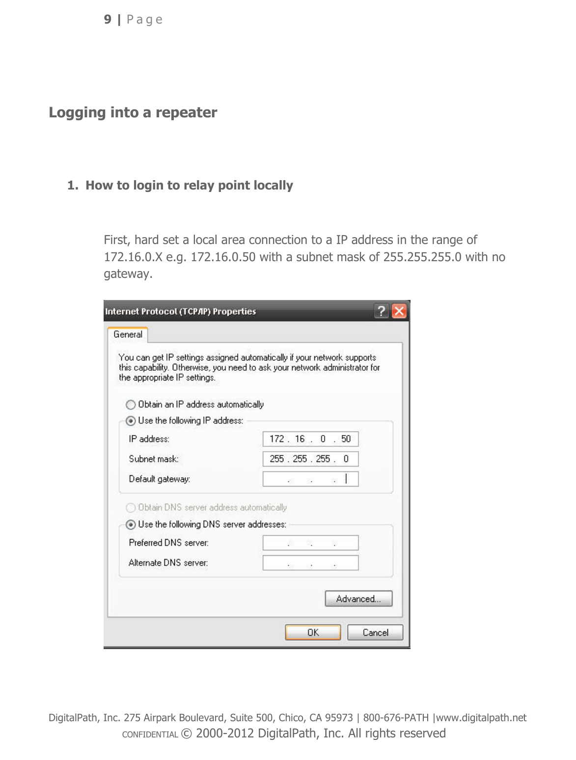
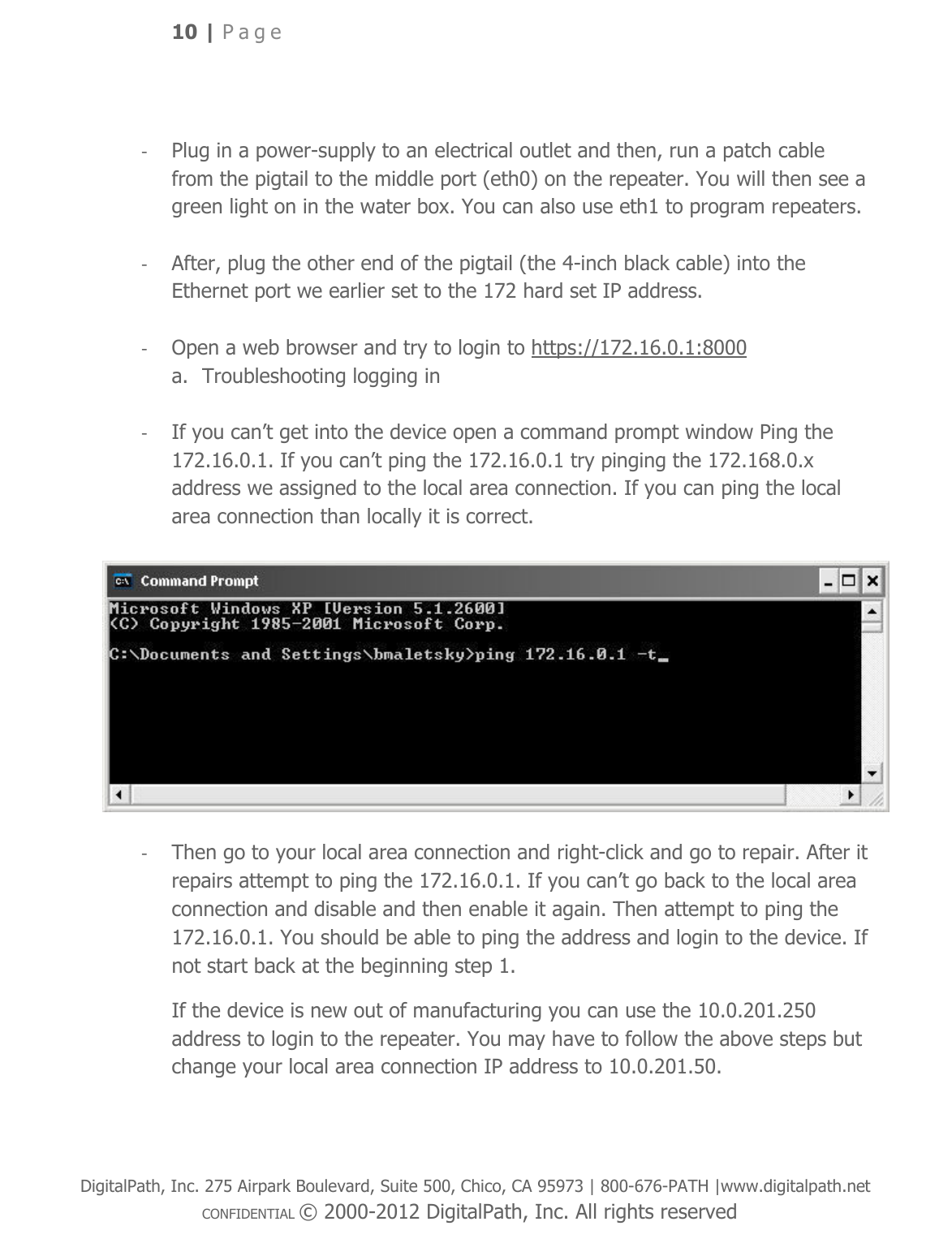
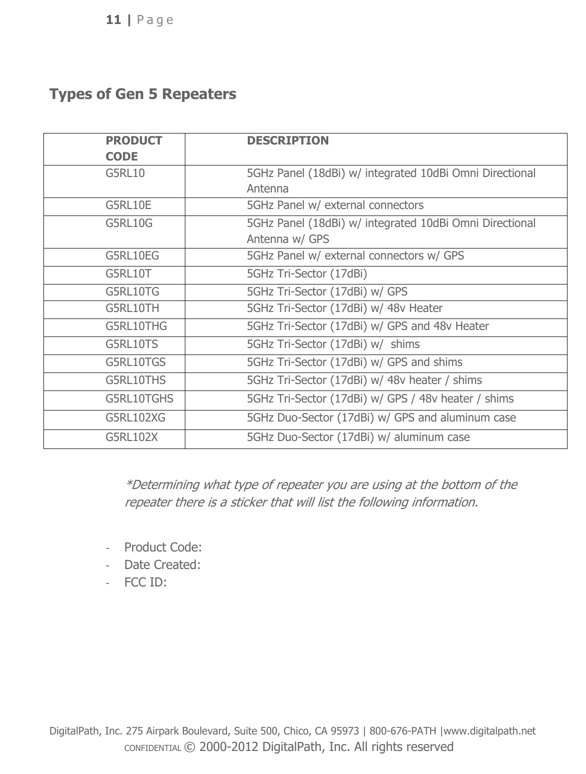
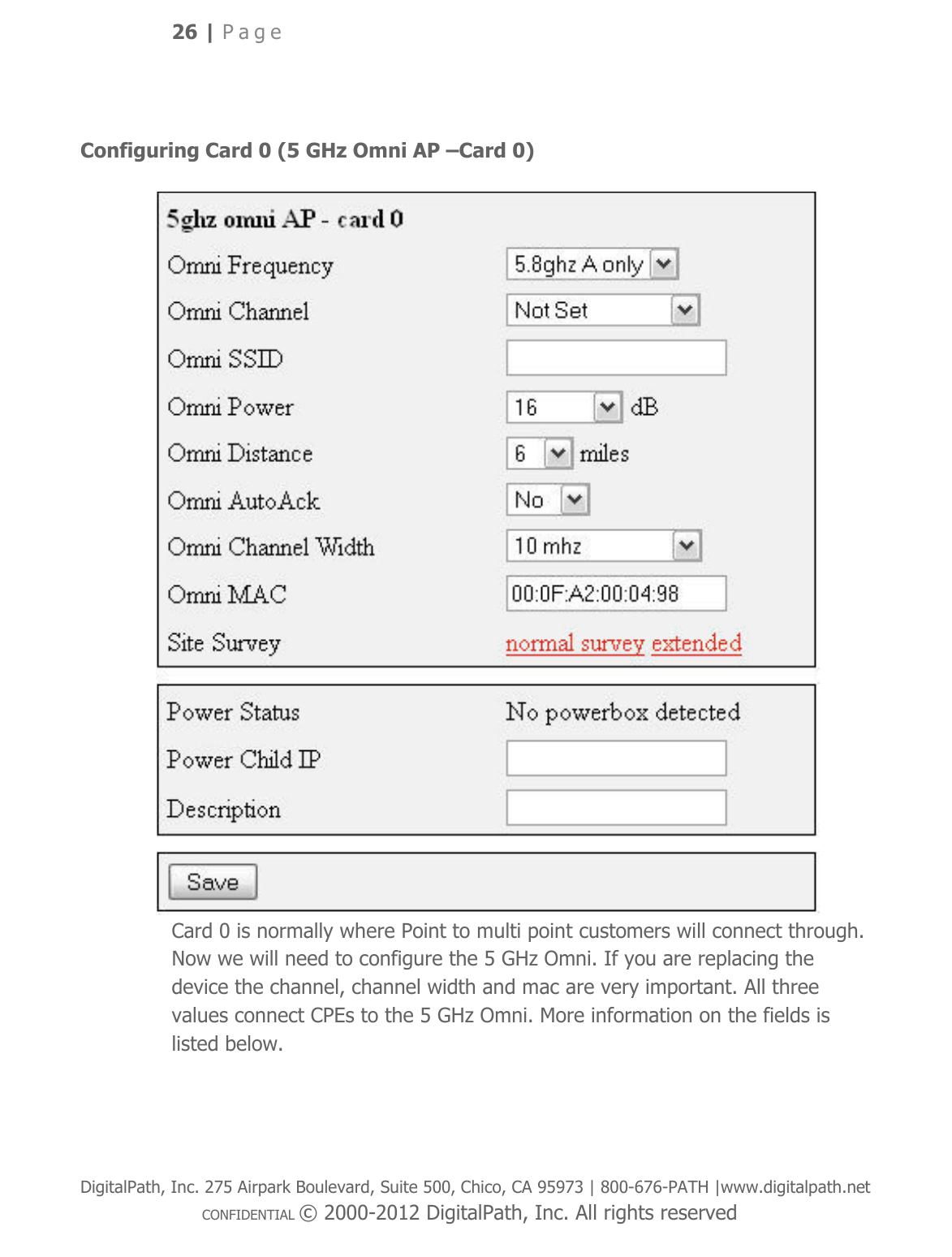
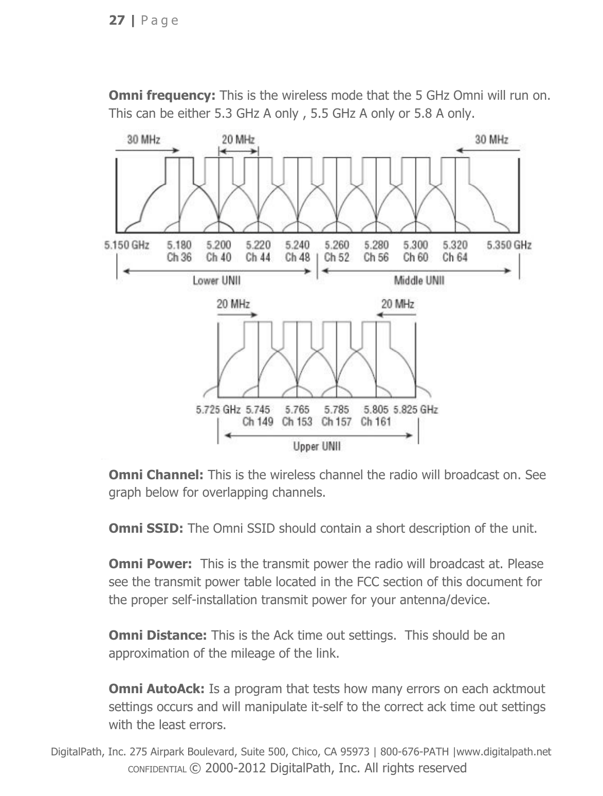
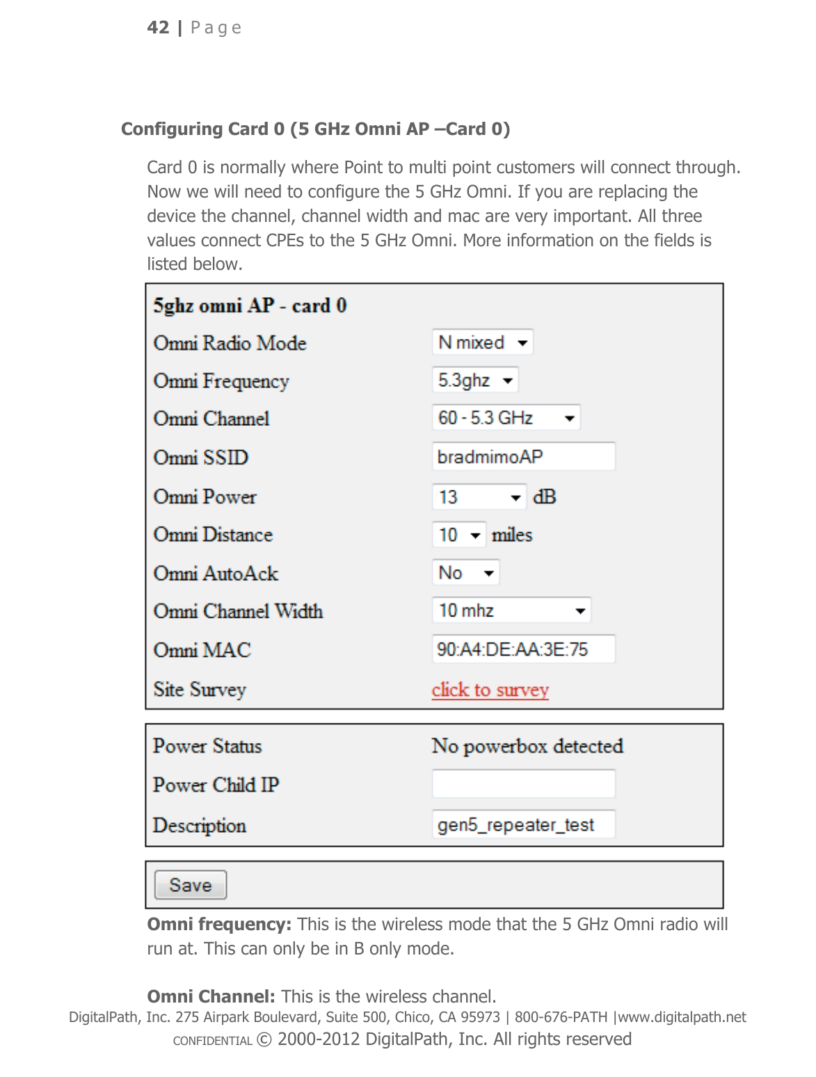
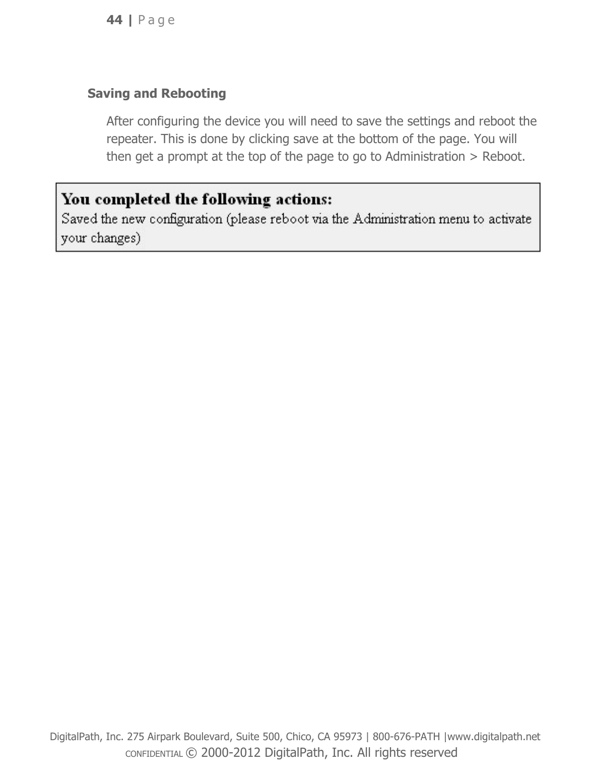


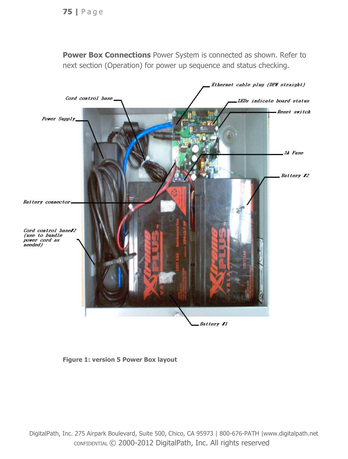

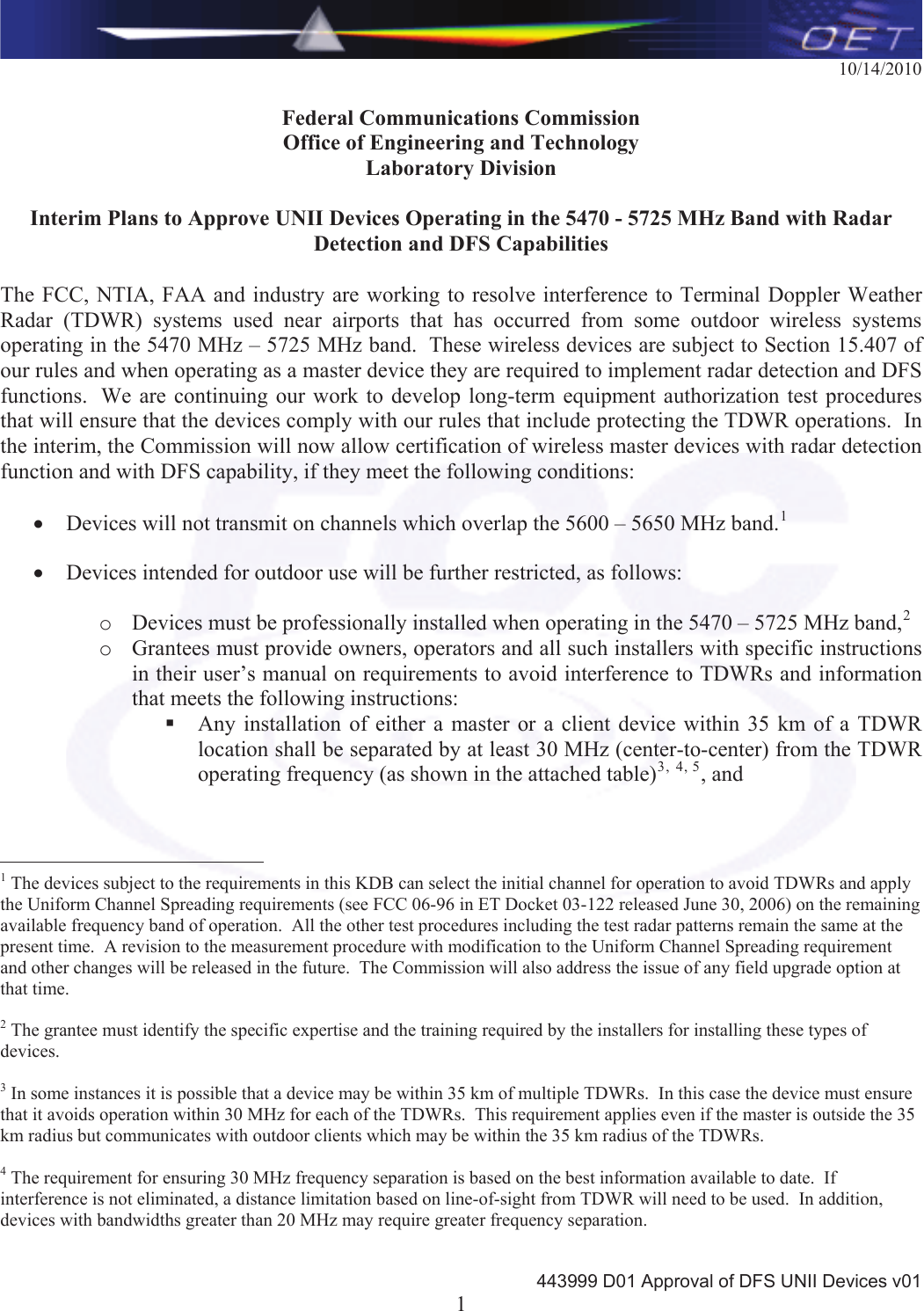
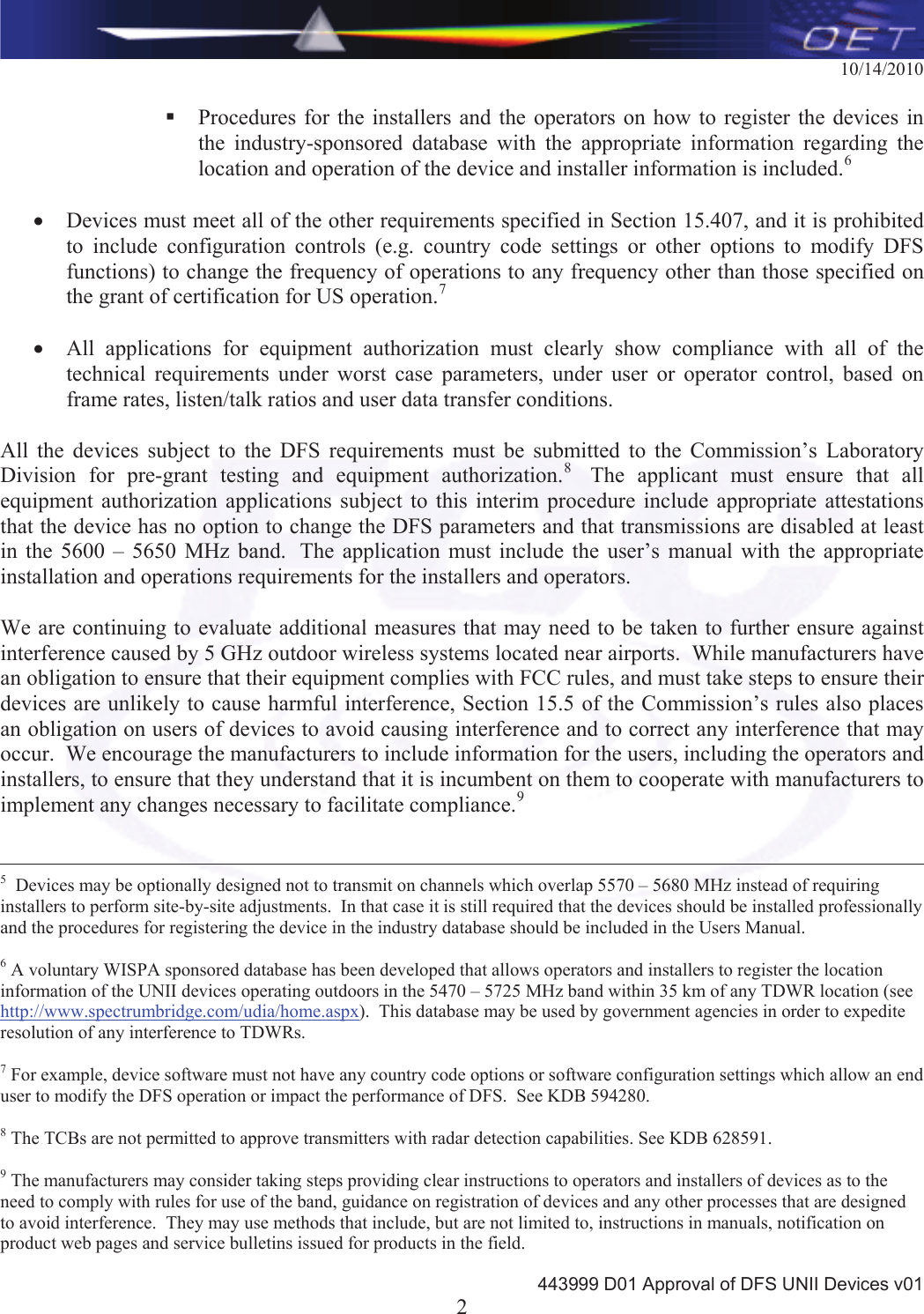
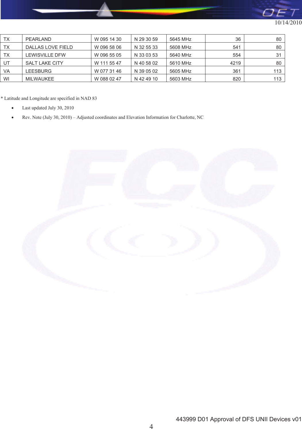
![10/14/2010 443999 D01 Approval of DFS UNII Devices v01 3TDWR Location Information* STATE CITY LONGITUDE LATITUDE FREQUENCYTERRAIN ELEVATION (MSL) [ft] ANTENNA HEIGHT ABOVE TERRAIN [ft] AZ PHOENIX W 112 09 46 N 33 25 14 5610 MHz 1024 64CO DENVER W 104 31 35 N 39 43 39 5615 MHz 5643 64FL FT LAUDERDALE W 080 20 39 N 26 08 36 5645 MHz 7 113FL MIAMI W 080 29 28 N 25 45 27 5605 MHz 10 113FL ORLANDO W 081 19 33 N 28 20 37 5640 MHz 72 97FL TAMPA W 082 31 04 N 27 51 35 5620 MHz 14 80FL WEST PALM BEACH W 080 16 23 N 26 41 17 5615 MHz 20 113GA ATLANTA W 084 15 44 N 33 38 48 5615 MHz 962 113IL MCCOOK W 087 51 31 N 41 47 50 5615 MHz 646 97IL CRESTWOOD W 087 43 47 N 41 39 05 5645 MHz 663 113IN INDIANAPOLIS W 086 26 08 N 39 38 14 5605 MHz 751 97KS WICHITA W 097 26 13 N 37 30 26 5603 MHz 1270 80KY COVINGTON CINCINNATI W 084 34 48 N 38 53 53 5610 MHz 942 97KY LOUISVILLE W 085 36 38 N 38 02 45 5646 MHz 617 113LA NEW ORLEANS W 090 24 11 N 30 01 18 5645 MHz 2 97MA BOSTON W 070 56 01 N 42 09 30 5610 MHz 151 113MD BRANDYWINE W 076 50 42 N 38 41 43 5635 MHz 233 113MD BENFIELD W 076 37 48 N 39 05 23 5645 MHz 184 113MD CLINTON W 076 57 43 N 38 45 32 5615 MHz 249 97MI DETROIT W 083 30 54 N 42 06 40 5615 MHz 656 113MN MINNEAPOLIS W 092 55 58 N 44 52 17 5610 MHz 1040 80MO KANSAS CITY W 094 44 31 N 39 29 55 5605 MHz 1040 64MO SAINT LOUIS W 090 29 21 N 38 48 20 5610 MHz 551 97MS DESOTO COUNTY W 089 59 33 N 34 53 45 5610 MHz 371 113NC CHARLOTTE W 080 53 06 N 35 20 14 5608 MHz 757 113NC RALEIGH DURHAM W 078 41 50 N 36 00 07 5647 MHz 400 113NJ WOODBRIDGE W 074 16 13 N 40 35 37 5620 MHz 19 113NJ PENNSAUKEN W 075 04 12 N 39 56 57 5610 MHz 39 113NV LAS VEGAS W 115 00 26 N 36 08 37 5645 MHz 1995 64NY FLOYD BENNETT FIELD W 073 52 49 N 40 35 20 5647 MHz 8 97OH DAYTON W 084 07 23 N 40 01 19 5640 MHz 922 97OH CLEVELAND W 082 00 28 N 41 17 23 5645 MHz 817 113OH COLUMBUS W 082 42 55 N 40 00 20 5605 MHz 1037 113OK AERO. CTR TDWR #1 W 097 37 31 N 35 24 19 5610 MHz 1285 80OK AERO. CTR TDWR #2 W 097 37 43 N 35 23 34 5620 MHz 1293 97OK TULSA W 095 49 34 N 36 04 14 5605 MHz 712 113OK OKLAHOMA CITY W 097 30 36 N 35 16 34 5603 MHz 1195 64PA HANOVER W 080 29 10 N 40 30 05 5615 MHz 1266 113PR SAN JUAN W 066 10 46 N 18 28 26 5610 MHz 59 113TN NASHVILLE W 086 39 42 N 35 58 47 5605 MHz 722 97TX HOUSTON INTERCONTL W 095 34 01 N 30 03 54 5605 MHz 154 97](https://usermanual.wiki/DigitalPath/G5RL10/User-Guide-1961338-Page-85.png)