DigitalPath G5RL10 Gen5 Repeater User Manual FCC OET TDWR SITES
DigitalPath, Inc. Gen5 Repeater FCC OET TDWR SITES
Users Manual

1 | P a g e
DigitalPath, Inc. 275 Airpark Boulevar
CONFIDENTIAL
© 2000
Gen
Docu
levard, Suite 500, C
hico, CA 95973 | 800-676-
PATH |ww
2000
-2012
DigitalPath, Inc. All rights reserved
Generation
5
ocumentation
Manual:
Software v
Date: 5/
2
|www.digitalpath.net
ved
al:
Beta version 1
are version 5014
2
/2013

2 | P a g e
DigitalPath, Inc. 275 Airpark Boulevard, Suite 500, Chico, CA 95973 | 800-676-PATH |www.digitalpath.net
CONFIDENTIAL © 2000-2012 DigitalPath, Inc. All rights reserved
Table of Contents
Logging into a repeater ............................................................................................ 9
1.
How to login to relay point locally ................................................................. 9
Types of Gen 5 Repeaters ....................................................................................... 11
Generation 5 Device Modes ..................................................................................... 12
1.
Uplink Router ............................................................................................. 12
2.
Downlink Router ........................................................................................ 12
3.
Downlink Bridge ......................................................................................... 12
4.
Uplink Bridge ............................................................................................. 12
Configuring a Uplink Router .................................................................................... 13
Configuring The Backhaul – (Card 1) .................................................................... 14
Client IP .......................................................................................................... 14
Client Netmask: ............................................................................................... 14
Gateway: ........................................................................................................ 14
Configuring the Router – (Card 0, eth0, eth1) ....................................................... 14
Router IP: ....................................................................................................... 14
Router Netmask: ............................................................................................. 14
Configuring Card 1 (5 GHz directional uplink client) ............................................... 15
Upstream MAC: ............................................................................................... 16
Uplink frequency: ............................................................................................ 16
Uplink channel: ............................................................................................... 16
Uplink SSID: .................................................................................................... 16
Uplink Power: .................................................................................................. 16
Uplink Distance: .............................................................................................. 16
Uplink AutoAck: ............................................................................................... 16
Uplink Channel Width: ..................................................................................... 16
Uplink Mac: ..................................................................................................... 16
Site Survey: .................................................................................................... 17
Configuring Card 0 (5 GHz Omni AP) .................................................................... 18
Omni frequency: .............................................................................................. 19

3 | P a g e
DigitalPath, Inc. 275 Airpark Boulevard, Suite 500, Chico, CA 95973 | 800-676-PATH |www.digitalpath.net
CONFIDENTIAL © 2000-2012 DigitalPath, Inc. All rights reserved
Omni Channel: ................................................................................................ 19
Omni SSID: ..................................................................................................... 19
Omni Power: ................................................................................................... 19
Omni Distance: ................................................................................................ 19
Omni AutoAck: ................................................................................................ 19
Omni Channel Width: ....................................................................................... 19
Omni Mac: ...................................................................................................... 19
Site Survey: .................................................................................................... 19
Power Child IP: ............................................................................................... 19
Description: ..................................................................................................... 19
Saving and Rebooting ......................................................................................... 20
Configuring a Downlink Router ................................................................................ 21
Configuring The Backhaul – eth0: ........................................................................ 22
Ethernet IP: .................................................................................................... 22
Ethernet Netmask: ........................................................................................... 22
Gateway: ........................................................................................................ 22
Parent IP: ....................................................................................................... 22
Configuring the Router – (Card 0, Card 1, eth1)................................................... 23
Router IP: ....................................................................................................... 23
Router Netmask: ............................................................................................. 23
Configuring Card 1 (directional downlink AP- card 1) ............................................. 24
Downlink Frequency: ....................................................................................... 24
Downlink Channel: ........................................................................................... 24
Downlink SSID: ............................................................................................... 24
Downlink Power: ............................................................................................. 25
Downlink ......................................................................................................... 25
Downlink ......................................................................................................... 25
Downlink ......................................................................................................... 25
Downlink ......................................................................................................... 25
Site ................................................................................................................. 25
Configuring Card 0 (5 GHz Omni AP –Card 0) ....................................................... 26
Omni .............................................................................................................. 27
Omni Channel: ................................................................................................ 27

4 | P a g e
DigitalPath, Inc. 275 Airpark Boulevard, Suite 500, Chico, CA 95973 | 800-676-PATH |www.digitalpath.net
CONFIDENTIAL © 2000-2012 DigitalPath, Inc. All rights reserved
Omni SSID: ..................................................................................................... 27
Omni Distance: ................................................................................................ 27
Omni AutoAck: ................................................................................................ 27
Omni Channel Width: ....................................................................................... 28
Omni Mac: ...................................................................................................... 28
Site Survey: .................................................................................................... 28
Description: ..................................................................................................... 28
Identifying Types of Repeaters and Antennas .......................................................... 29
External Antennas ............................................................................................... 31
5GHZ 20dBi Dual Polarity Sector ....................................................................... 31
5GHZ 23dBi External Diamond .......................................................................... 31
5GHZ 2ft 29db Dish ......................................................................................... 32
Understanding the Status Page ............................................................................... 33
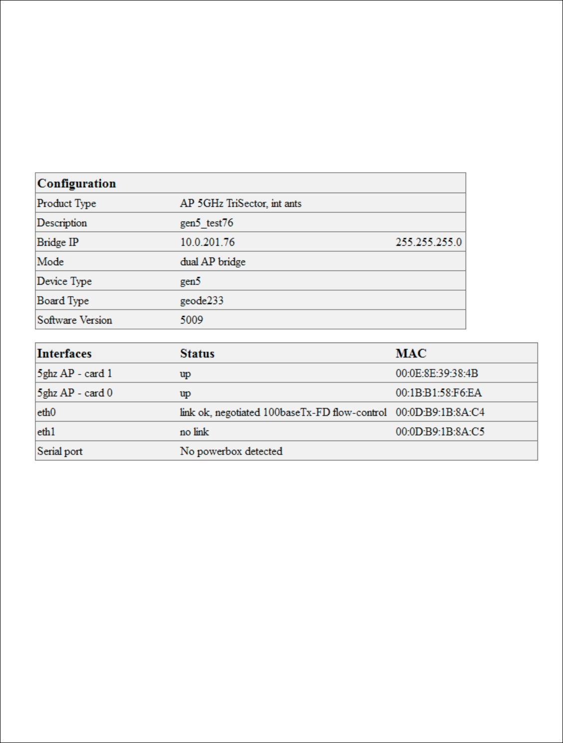
Understanding the General Tab ........................................................................... 33
Description: ..................................................................................................... 33
Router IP: ....................................................................................................... 33
Client IP: ......................................................................................................... 33
Mode: ............................................................................................................. 33
Device Type: ................................................................................................... 34
Software version: ............................................................................................ 34
Interfaces: ...................................................................................................... 34
Understanding and using the Stations tab ............................................................ 35
Change Channel .............................................................................................. 35
Radio Check .................................................................................................... 36
DHCP .............................................................................................................. 36
Speed Test ......................................................................................................... 37
Configuring a Uplink Bridge ..................................................................................... 38
IP Address ...................................................................................................... 39
Netmask ......................................................................................................... 39
Gateway ......................................................................................................... 39
Configuring Card 1 (5 GHz directional uplink client –card 1) ................................... 40
Upstream MAC ................................................................................................ 40
Uplink frequency ............................................................................................. 40

5 | P a g e
DigitalPath, Inc. 275 Airpark Boulevard, Suite 500, Chico, CA 95973 | 800-676-PATH |www.digitalpath.net
CONFIDENTIAL © 2000-2012 DigitalPath, Inc. All rights reserved
Uplink channel ................................................................................................. 40
Uplink SSID ..................................................................................................... 41
Uplink Power ................................................................................................... 41
Uplink Distance: .............................................................................................. 41
Uplink AutoAck ................................................................................................ 41
Uplink Channel Width....................................................................................... 41
Uplink Mac ...................................................................................................... 41
Site Survey: .................................................................................................... 41
Configuring Card 0 (5 GHz Omni AP –Card 0) ....................................................... 42
Omni frequency: .............................................................................................. 42
Omni Channel ................................................................................................. 42
Omni SSID: ..................................................................................................... 43
Omni Power: ................................................................................................... 43
Omni Distance: ................................................................................................ 43
Omni AutoAck: ................................................................................................ 43
Omni Channel Width: ....................................................................................... 43
Omni Mac: ...................................................................................................... 43
Site Survey: .................................................................................................... 43
Power Child IP: ............................................................................................... 43
Description: ..................................................................................................... 43
Saving and Rebooting ......................................................................................... 44
Configuring a Downlink Bridge ................................................................................ 45
IP Address ...................................................................................................... 45
Netmask: ........................................................................................................ 46
Gateway: ........................................................................................................ 46
Parent IP: ....................................................................................................... 46
Configuring Card 1 (directional downlink AP- card 1) ............................................. 47
Downlink Frequency: ....................................................................................... 47
Downlink Channel: ........................................................................................... 47
Downlink SSID: ............................................................................................... 47
Downlink Power: ............................................................................................. 47
Downlink Distance: .......................................................................................... 47
Downlink AutoAck: .......................................................................................... 48
Downlink Channel Width: ................................................................................. 48

6 | P a g e
DigitalPath, Inc. 275 Airpark Boulevard, Suite 500, Chico, CA 95973 | 800-676-PATH |www.digitalpath.net
CONFIDENTIAL © 2000-2012 DigitalPath, Inc. All rights reserved
Downlink Mac: ................................................................................................. 48
Site Survey: .................................................................................................... 48
Configuring Card 0 (5 GHz Omni AP –Card 0) ....................................................... 49
Omni frequency: .............................................................................................. 49
Omni Channel: ................................................................................................ 49
Omni SSID: ..................................................................................................... 50
Omni Distance: ................................................................................................ 50
Omni AutoAck: ................................................................................................ 50
Omni Channel Width: ....................................................................................... 50
Omni Mac: ...................................................................................................... 51
Site Survey: .................................................................................................... 51
Description: ..................................................................................................... 51
Understanding the Configure Page .......................................................................... 52
Understanding the Advanced Tab ........................................................................ 52
Automatic Noise Immunity (ANI ....................................................................... 52
RTS Threshold:................................................................................................ 52
Fragmentation Threshold: ................................................................................ 52
Aggregation: ................................................................................................... 52
Rx Chain Mask: ............................................................................................... 52
Tx Chain Mask: ................................................................................................ 53
Ethernet: ........................................................................................................ 53
Understanding the Routes Tab ............................................................................. 54
Understanding the Antennas Tab ......................................................................... 55
Description: ..................................................................................................... 55
Active Antenna: ............................................................................................... 55
Understanding the Administration Page ................................................................... 57
Reload Config ..................................................................................................... 57
Reboot: .............................................................................................................. 57
Reason: .......................................................................................................... 58
Description: ..................................................................................................... 58
Reset Config: .................................................................................................. 58
Initial Setup: ....................................................................................................... 58
Hardware Details: ............................................................................................ 58

7 | P a g e
DigitalPath, Inc. 275 Airpark Boulevard, Suite 500, Chico, CA 95973 | 800-676-PATH |www.digitalpath.net
CONFIDENTIAL © 2000-2012 DigitalPath, Inc. All rights reserved
5 GHz directional uplink client – card 1 ............................................................. 58
5 GHz Omni AP ................................................................................................ 58
Eth0 Mac Address: ........................................................................................... 58
FCC Compliance & Installation Statement ................................................................ 60
Definitions ....................................................................................................... 60
Statement ....................................................................................................... 60
Attention ......................................................................................................... 60
FCC statement 15.21(a) ................................................................................... 61
Professional Installation ................................................................................... 61
FCC statement 15.27(b) ................................................................................... 61
Parts List & Tune-Up Information ............................................................................ 62
External RF Cables for Connection to Modularized Connector Ports ..................... 62
Ethernet Surge Suppression ............................................................................. 62
Power Supply .................................................................................................. 62
Antenna ................................................................................................................. 63
Panel ................................................................................................................. 63
Omni-Directional ................................................................................................. 63
Sector ................................................................................................................ 63
Dish ................................................................................................................... 63
Channels ............................................................................................................... 64
Notice of FCC power compliance for transmit power settings .................................... 65
Version 5 Power User’s Manual ............................................................................... 72
System Diagram ................................................................................................. 73
Power system installation for a gen 5 repeater .................................................. 73
Power system installation for a 2 repeater site................................................... 74
CHMONv5 Board .............................................................................................. 76
Operation ........................................................................................................... 77
Powering Up a Version 5 .................................................................................. 77
LED Indicators ................................................................................................. 78
Button Operation ............................................................................................. 79
Lid Sensor ....................................................................................................... 79
Fuse Replacement ........................................................................................... 79
Heart-Beat Monitoring ......................................................................................... 81

8 | P a g e
DigitalPath, Inc. 275 Airpark Boulevard, Suite 500, Chico, CA 95973 | 800-676-PATH |www.digitalpath.net
CONFIDENTIAL © 2000-2012 DigitalPath, Inc. All rights reserved
Introduction: ................................................................................................... 81
ATTACHMENTS
FCC-OET TDWR NOTICE 10/14/2010 for 5470-5725 MHz w/ DFS
9 | P a g e
DigitalPath, Inc. 275 Airpark Boulevard, Suite 500, Chico, CA 95973 | 800-676-PATH |www.digitalpath.net
CONFIDENTIAL © 2000-2012 DigitalPath, Inc. All rights reserved
Logging into a repeater
1. How to login to relay point locally
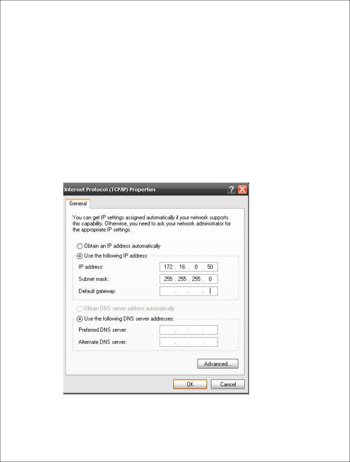
First, hard set a local area connection to a IP address in the range of
172.16.0.X e.g. 172.16.0.50 with a subnet mask of 255.255.255.0 with no
gateway.
10 | P a g e
DigitalPath, Inc. 275 Airpark Boulevard, Suite 500, Chico, CA 95973 | 800-676-PATH |www.digitalpath.net
CONFIDENTIAL © 2000-2012 DigitalPath, Inc. All rights reserved
- Plug in a power-supply to an electrical outlet and then, run a patch cable
from the pigtail to the middle port (eth0) on the repeater. You will then see a
green light on in the water box. You can also use eth1 to program repeaters.
- After, plug the other end of the pigtail (the 4-inch black cable) into the
Ethernet port we earlier set to the 172 hard set IP address.
- Open a web browser and try to login to https://172.16.0.1:8000
a. Troubleshooting logging in
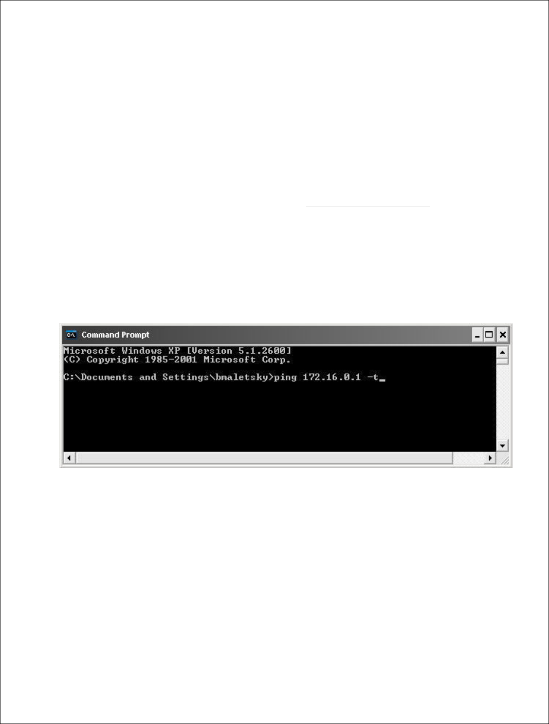
- If you can’t get into the device open a command prompt window Ping the
172.16.0.1. If you can’t ping the 172.16.0.1 try pinging the 172.168.0.x
address we assigned to the local area connection. If you can ping the local
area connection than locally it is correct.
- Then go to your local area connection and right-click and go to repair. After it
repairs attempt to ping the 172.16.0.1. If you can’t go back to the local area
connection and disable and then enable it again. Then attempt to ping the
172.16.0.1. You should be able to ping the address and login to the device. If
not start back at the beginning step 1.
If the device is new out of manufacturing you can use the 10.0.201.250
address to login to the repeater. You may have to follow the above steps but
change your local area connection IP address to 10.0.201.50.

11 | P a g e
DigitalPath, Inc. 275 Airpark Boulevard, Suite 500, Chico, CA 95973 | 800-676-PATH |www.digitalpath.net
CONFIDENTIAL © 2000-2012 DigitalPath, Inc. All rights reserved
Types of Gen 5 Repeaters
PRODUCT
CODE
DESCRIPTION
G5RL10
5GHz Panel (18dBi) w/ integrated 10dBi Omni Directional
Antenna
G5RL10E
5GHz Panel w/ external connectors
G5RL10G
5GHz Panel (18dBi) w/ integrated 10dBi Omni Directional
Antenna w/ GPS
G5RL10EG
5GHz Panel w/
external connectors w/ GPS
G5RL10T
5GHz Tri
-
Sector (17dBi)
G5RL10TG
5GHz Tri
-
Sector (17dBi) w/ GPS
G5RL10TH
5GHz Tri
-
Sector (17dBi) w/ 48v Heater
G5RL10THG
5GHz Tri
-
Sector (17dBi) w/ GPS and 48v Heater
G5RL10TS
5GHz Tri
-
Sector (17dBi) w/ shims
G5RL10TGS
5GHz Tri
-
Sector (17dBi) w/ GPS and shims
G5RL10THS
5GHz Tri
-
Sector (17dBi) w/ 48v heater / shims
G5RL10TGHS
5GHz Tri
-
Sector (17dBi) w/ GPS / 48v heater / shims
G5RL10
2XG
5GHz Duo
-
Sector (17dBi) w/ GPS
and aluminum case
G5RL10
2X
5GHz Duo
-
Sector (17dBi) w/ aluminum case
*Determining what type of repeater you are using at the bottom of the
repeater there is a sticker that will list the following information.
- Product Code:
- Date Created:
- FCC ID:

12 | P a g e
DigitalPath, Inc. 275 Airpark Boulevard, Suite 500, Chico, CA 95973 | 800-676-PATH |www.digitalpath.net
CONFIDENTIAL © 2000-2012 DigitalPath, Inc. All rights reserved
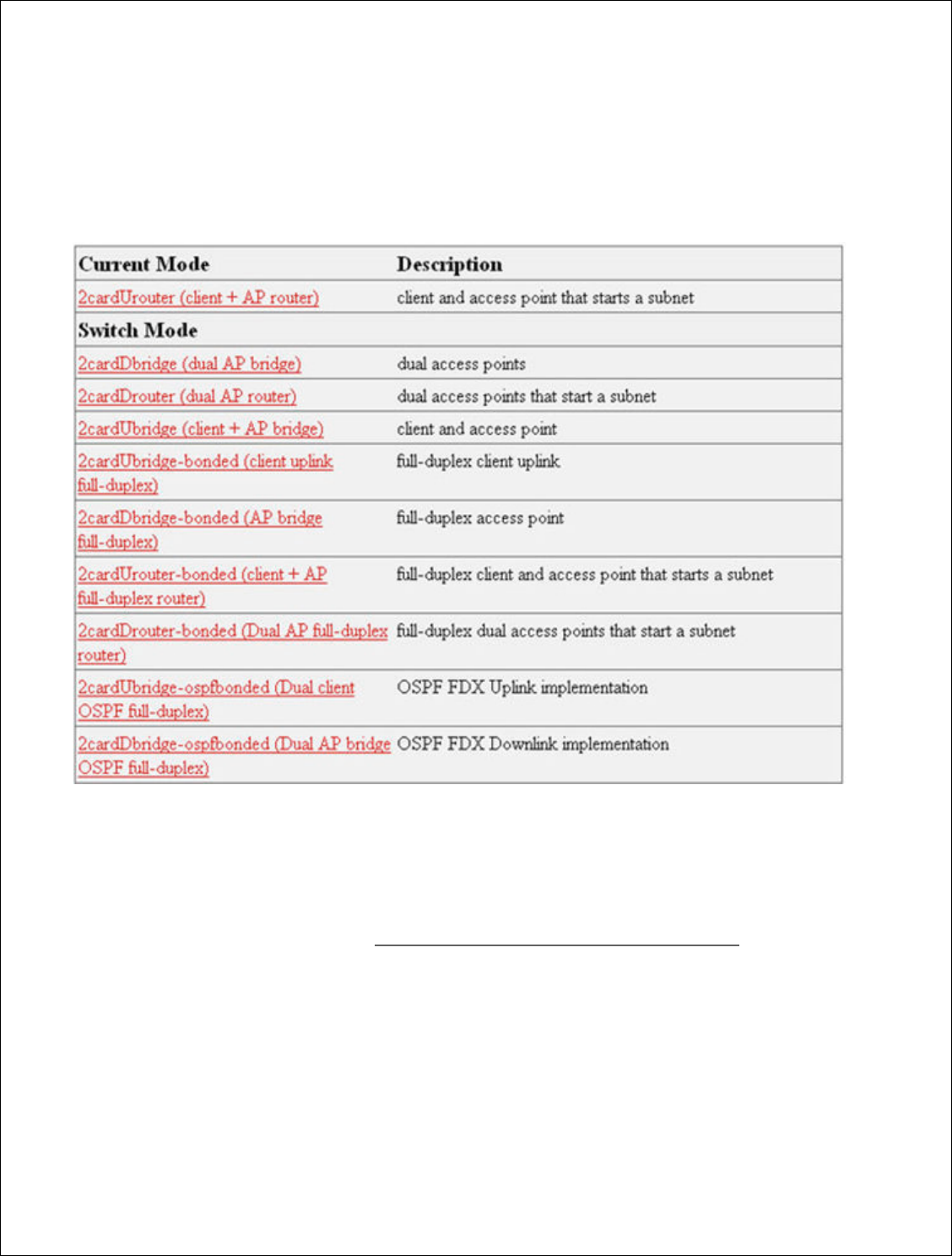
Generation 5 Device Modes
1. Uplink Router
An Uplink Router will connect the site and start a new routed subnet.
2. Downlink Router
Downlink router mode will feed other relays and or connect customers on
external devices or an Omni-directional antenna. It will also start a new
routed subnet.
3. Downlink Bridge
Downlink Bridge will be bridged off the sites current subnet and feed another
relay and or connect customers on external devices or an Omni directional
antenna.
4. Uplink Bridge
Uplink Bridge will connect the site and be in the same bridge 1group as the
downlink that feeds it.
13 | P a g e
DigitalPath, Inc. 275 Airpark Boulevar
CONFIDENTIAL
© 2000
Configuring
a Uplink Rou
1.
After logging into the rel
(client + AP router)
2.
After choosing the mode
redirect you to the Config
router is knowing
what y
3. Backhaul – Card1
. The th
bridged information for t
connect to the downlink
repeater is 10.10.21.1 th
10.10.21.x (2-65 240
-
levard, Suite 500, C
hico, CA 95973 | 800-676-
PATH |ww
2000
-2012
DigitalPath, Inc. All rights reserved
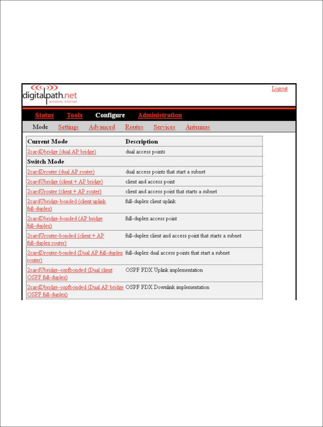
k Router
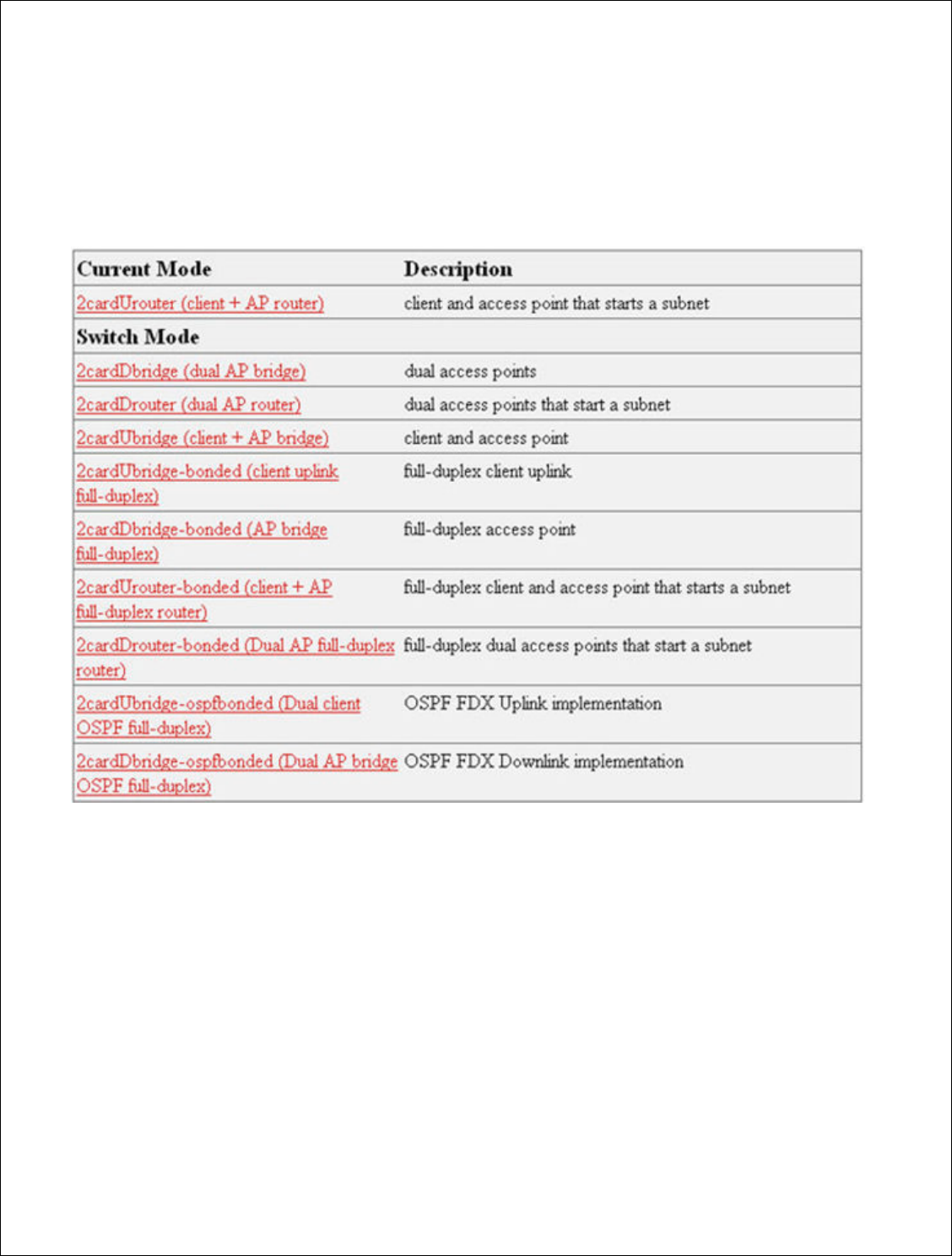
e relay go to Configure > Mode. Next, choose 2
ode of the device to 2cardUrouter (client + AP
onfigure > Settings page. The first part of conf
hat your IP address is
.
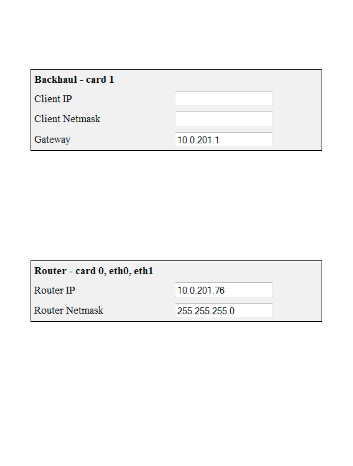
he three fields at the top of the configuration pa
for the repeater. This is wh
at the repeater will t
link that feeds it
e.g.
if the parent device feedin
.1 then the Client IP address (or eth0 IP addres
-
254).
|www.digitalpath.net
ved
se 2cardUrouter
AP router) it
will
configuring a
on page are the
will talk on to
eding the
dress) will be
14 | P a g e
DigitalPath, Inc. 275 Airpark Boulevar
CONFIDENTIAL
© 2000
Configuring The Backhaul
Client IP
: The bridged IP a
Client Netmask:
This field
Gateway:
This field represe
wi
ll be the gateway of the ro
Configuring the Router –
(C
Router IP:
This is the routi
the device and wired repeat
Router Netmask:
This is
normally be a /24 class C
Ne
levard, Suite 500, C
hico, CA 95973 | 800-676-
PATH |ww
2000
-2012
DigitalPath, Inc. All rights reserved
– (Card 1)
IP address connecting the two sites on the br1
field represents the subnet that the br1 bridge g
presents your gateway from this device. In a ro
he router in your br1 bridge group IP address.
(Card 0, eth0, eth1)
routing IP address that will feed all wireless cus
peaters on eth1. This wil
l normally be a “.1”
e.g
is is the subnet mask for the
routing IP address.
Netmask
(255.255.255.0).
|www.digitalpath.net
ved
br1 bridge group.
dge group contains.
a router mode it
ss.
customers off of
e.g.
10.10.21.1.
ress. This will
15 | P a g e
DigitalPath, Inc. 275 Airpark Boulevar
CONFIDENTIAL
© 2000
Configuring Card 1 (5 GHz
Next, to connect the
directional uplink
clien
extended. This will su
After finding the appr
labeled
>select. This
and uplink channel.
levard, Suite 500, C
hico, CA 95973 | 800-676-
PATH |ww
2000
-2012
DigitalPath, Inc. All rights reserved
directional uplink client)
the site we
will need to do a survey from card 1
client). Scroll down to the site
survey column a
ill survey for all available wireless device in the
appropriate downlink to connect t
o si
mply press
This will enter the upstream Mac address, uplink
el.
|www.digitalpath.net
ved
ard 1 (
5 GHz
mn and
click
the
5 GHz band.
press the red link
plink frequency,

16 | P a g e
DigitalPath, Inc. 275 Airpark Boulevard, Suite 500, Chico, CA 95973 | 800-676-PATH |www.digitalpath.net
CONFIDENTIAL © 2000-2012 DigitalPath, Inc. All rights reserved
You will have to put in a SSID of the sites name followed by UL. Set the
correct txpower and mileage. More information on the fields is listed below.
Upstream MAC: This is the MAC address of the device the uplink will be
connecting to.
Uplink frequency: The current frequency band the radio will broadcast in.
5.3 GHz A only 5.5 GHz A only and 5.8 GHz A only.
Uplink channel: This will be dependent upon the uplink frequency field.
Uplink SSID: It is helpful to set this field to something related to the
location of the device. There can be no spaces in the SSID.
Uplink Power: This is the transmit power the radio will broadcast at.
Uplink Distance: This is the ack time-out setting that calculates how far to
send the data. Setting the distance to 10% longer than the actual distance
between repeaters is recommended.
Uplink AutoAck: Is a program that tests how many errors on each
acktmout settings occurs and will manipulate it-self to the correct ack time
out settings with the least errors.
*Only use this on far shots that are affected by speeds or duplicate packets
due to a fluctuating ack value.
Uplink Channel Width: Channel width can be set to 20 MHz or 10 MHz.
This is the channel space the current frequency will broadcast at. 20 MHz will
give you more throughput and is recommended for infill, backhaul repeaters
and uplinks. 10 MHz is recommended for point to multi-point connections.
Uplink Mac: The uplink mac is one mac address that is associated to the
card1 br1 bridge group. This mac will never have to be cloned when replacing
devices.

17 | P a g e
DigitalPath, Inc. 275 Airpark Boulevard, Suite 500, Chico, CA 95973 | 800-676-PATH |www.digitalpath.net
CONFIDENTIAL © 2000-2012 DigitalPath, Inc. All rights reserved
Site Survey: Will survey all available wireless devices in the area. An
extended survey will show you more devices and will survey longer. An
extended survey is recommended when trying to find wireless devices.
18 | P a g e
DigitalPath, Inc. 275 Airpark Boulevar
CONFIDENTIAL
© 2000
Configuring Card 0 (
5 GHz O
Card 0 is normally
wh
through. Now we
will
If you are replacing the device
All three values connect CPE
s to
listed below.
levard, Suite 500, C
hico, CA 95973 | 800-676-
PATH |ww
2000
-2012
DigitalPath, Inc. All rights reserved
Hz O
mni AP)
where Point to multi point
subscribers
will con
will need to configure the
5 GHz Omni.
vice the channel, channel width and mac are ve
s to the
5 GHz Omni. More informa
tion on the
|www.digitalpath.net
ved
ll connect
e very important.
the fields is

19 | P a g e
DigitalPath, Inc. 275 Airpark Boulevard, Suite 500, Chico, CA 95973 | 800-676-PATH |www.digitalpath.net
CONFIDENTIAL © 2000-2012 DigitalPath, Inc. All rights reserved
Omni frequency: This is the wireless mode that the radio will run at.
Omni Channel: This is the wireless channel the radio will run at.
Omni SSID: This is the SSID that will be seen when associating to this radio.
Omni Power: This is the transmit power the radio will broadcast at.
Omni Distance: This is the Ack time out settings.
Omni AutoAck: Is a program that tests how many errors on each acktmout
settings occurs and will manipulate it-self to the correct ack time out settings
with the least errors.
Omni Channel Width: 10 MHz or 20 MHz is recommended.
Omni Mac: The Omni mac address is the mac address CPEs will connect to.
This may need to be cloned if you are replacing a device.
Site Survey: Will survey all available wireless devices in the area. An
extended survey will show you more devices and will survey longer. An
extended survey is recommended when trying to find wireless devices.
Power Child IP: This is used for devices that are daisy chained off of each
other. This field is normally not filled out. Nothing is affected if not filled out it
is just for reference.
Description: This is the site location.
20 | P a g e
DigitalPath, Inc. 275 Airpark Boulevard, Suite 500, Chico, CA 95973 | 800-676-PATH |www.digitalpath.net
CONFIDENTIAL © 2000-2012 DigitalPath, Inc. All rights reserved
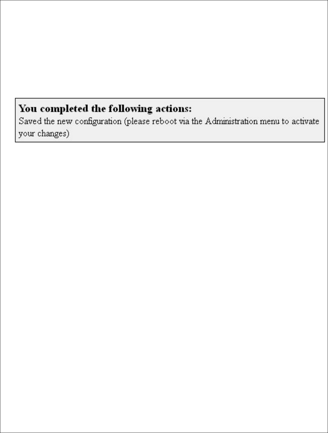
Saving and Rebooting
After configuring the device you will need to save the settings and reboot the
repeater. This is done by clicking save at the bottom of the page. You will then
get a prompt at the top of the page to go to Administration > Reboot.
21 | P a g e
DigitalPath, Inc. 275 Airpark Boulevar
CONFIDENTIAL
© 2000
Configuring a
Downlink
1.
After logging into the rel
(dual AP router)
2.
After choosing the mode
redirect you to the Config
router is to know
your IP
configuration data off the
please s
ee the section on
levard, Suite 500, C
hico, CA 95973 | 800-676-
PATH |ww
2000
-2012
DigitalPath, Inc. All rights reserved
link Router
e relay go to
Configure > Mode. Next,
choose 2
ode of the device to 2cardUrouter (
dual AP rou
onfigure > Settings page. The first part of
conf
ur IP addresses. If replacing a device s
imply
pul
ff the device.
If you are configuring a new
Down
on on
Cre
ating Routers and what to check
|www.digitalpath.net
ved
se 2cardD
router
router
) it will
configuring a
pull the
Downlink
Router
eck
22 | P a g e
DigitalPath, Inc. 275 Airpark Boulevar
CONFIDENTIAL
© 2000
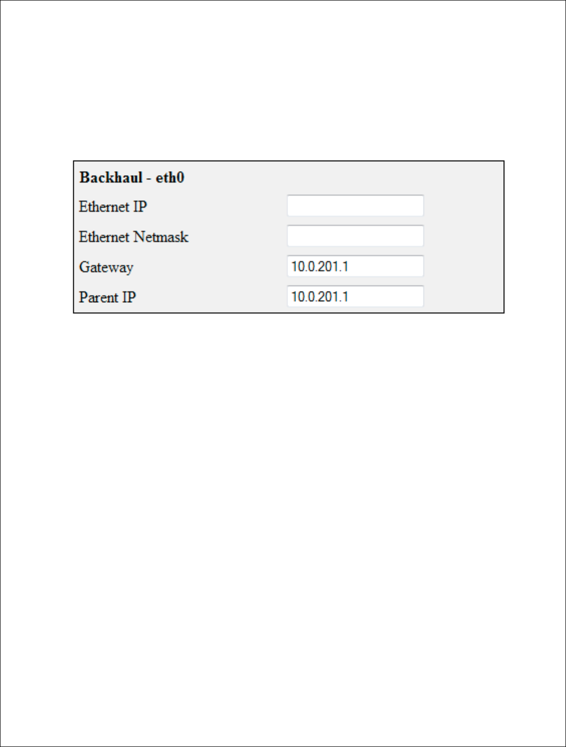
Configuring The B
ackhaul
The four fields at the top of
the repeater.
This informatio
uplink or switch.
Ethernet IP:
This is
the repeater is being
*It is important
th
or it will not come
Ethernet Netmask
announced on the sw
Gateway:
This is the
Parent IP:
This will
uplink at the site. Thi
this address.
levard, Suite 500, C
hico, CA 95973 | 800-676-
PATH |ww
2000
-2012
DigitalPath, Inc. All rights reserved
ul
– eth0:
op of the configuration page are the b
ridg
ed info
mation is for connecting the downlink to an exis
is is the bridged IP address on the local subnet
eing installed on.
that the data cable be plugged into eth0 on t
ome online as a router
.
ask
:
This is the local bridge groups subnet mas
e switch or the uplink at the location.
is the Gatew
ay of the local bridge group at the l
will either be the managed switch at the locatio
. This is important since the parent ping watchd
|www.digitalpath.net
ved
d information for
existing sites
bnet on the site
on the repeater
mask either being
the location.
cation or the
tchdog will ping
23 | P a g e
DigitalPath, Inc. 275 Airpark Boulevar
CONFIDENTIAL
© 2000
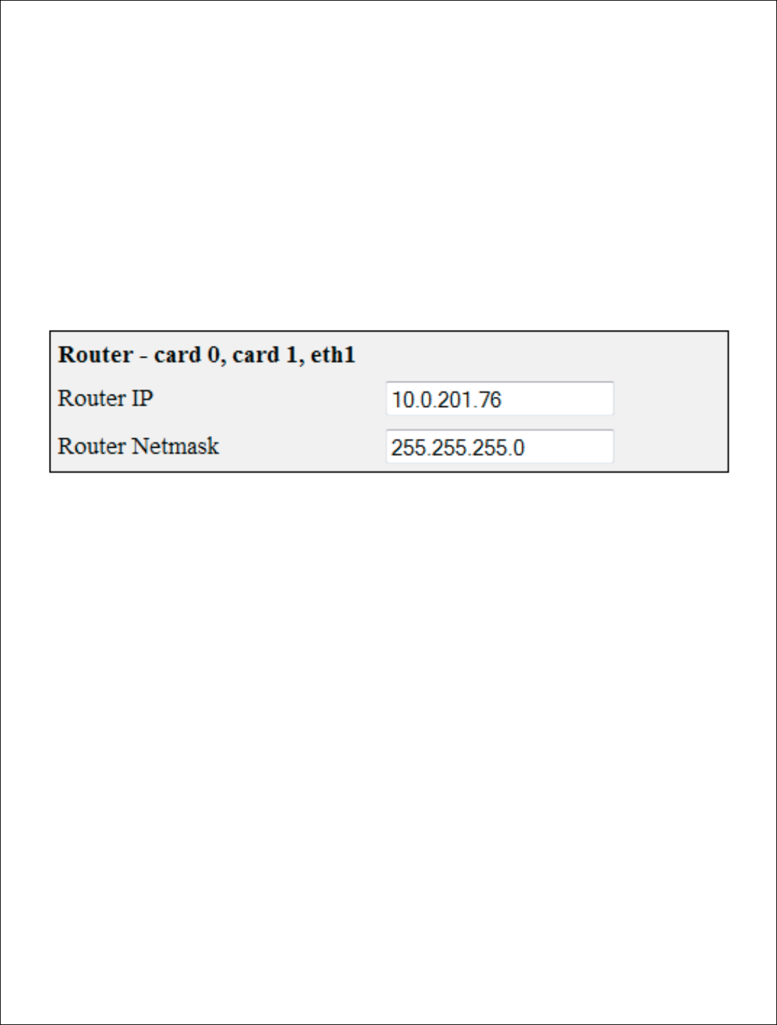
Configuring the Router –
(C
Router IP:
This is th
off of the device and
10.10.21.1.
Router Netmask:
majority of
repeaters
levard, Suite 500, C
hico, CA 95973 | 800-676-
PATH |ww
2000
-2012
DigitalPath, Inc. All rights reserved
(Card 0, Card 1
, eth1)
is the routing IP address that will feed all wirele
and wired repeaters on eth1. This will
usually
This is the subnet mask for the
routing IP a
ters
normally use a /24 class C Netmask
(255.2
|www.digitalpath.net
ved
ireless customers
be a “.1” e.g.
IP address. Th
e
55.255.255.0).
24 | P a g e
DigitalPath, Inc. 275 Airpark Boulevard, Suite 500, Chico, CA 95973 | 800-676-PATH |www.digitalpath.net
CONFIDENTIAL © 2000-2012 DigitalPath, Inc. All rights reserved
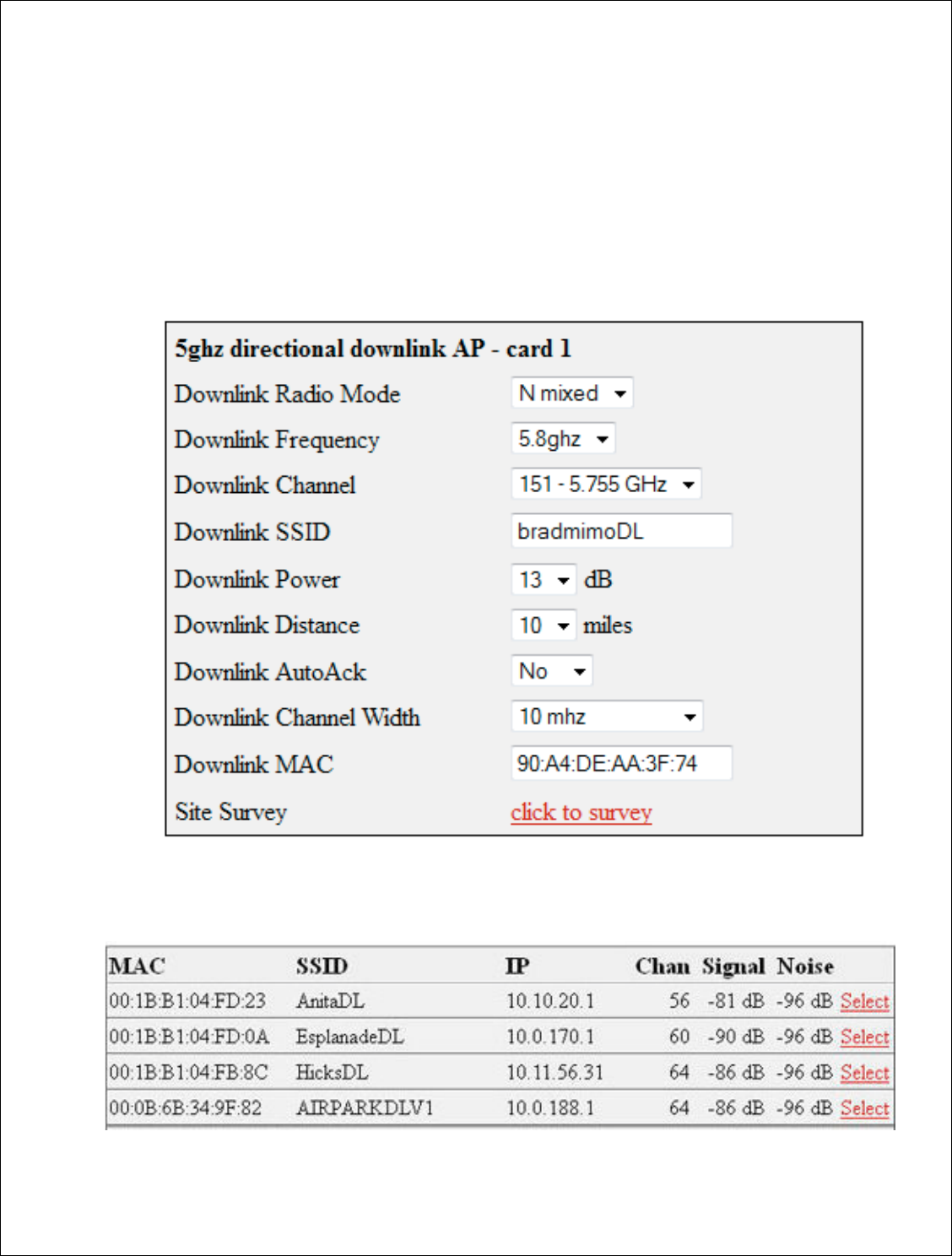
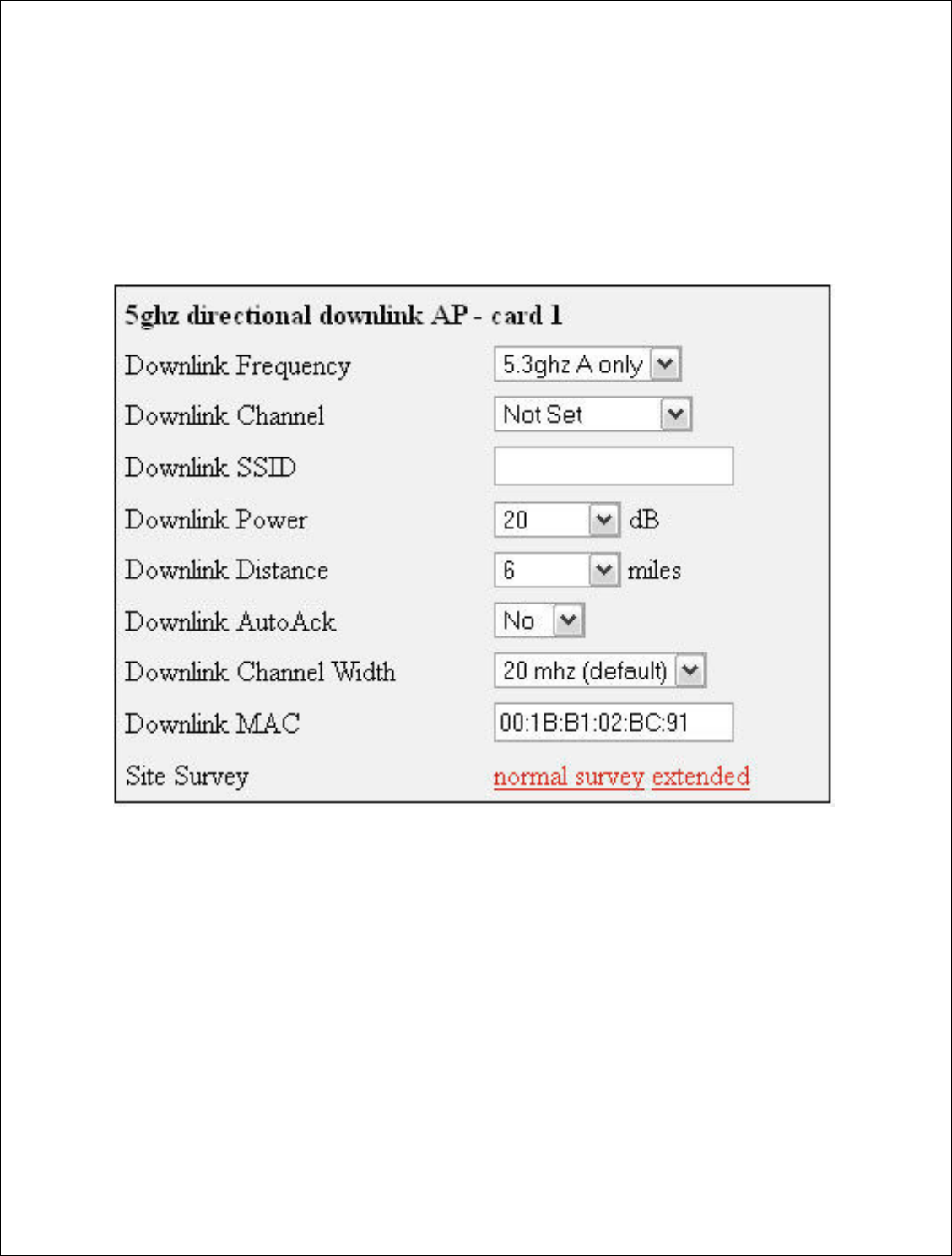
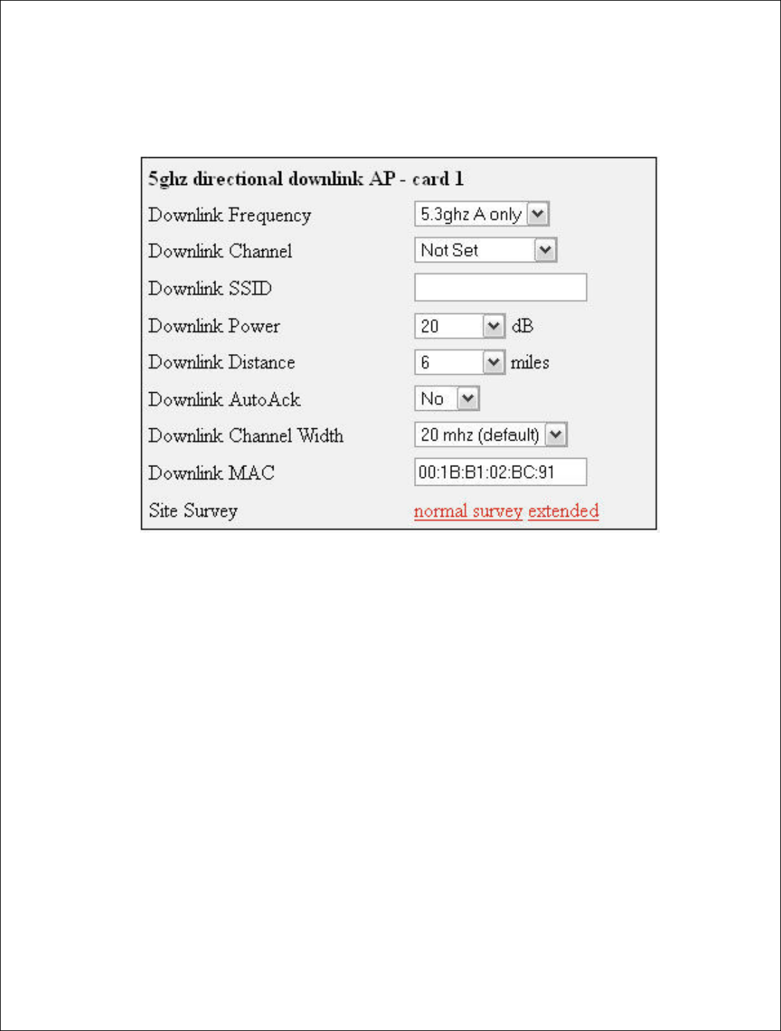
Configuring Card 1 (directional downlink AP- card 1)
Next, If replacing a device simply pull the configuration data from the device
being replaced. If it is a new device label the device appropriately e.g. if it
feeds 701 Main St. label the SSID as 701mainstDL).
Downlink Frequency: This is the frequency band the radio will broadcast
in.
Downlink Channel: This will be a downlink channel that will feed either a
relay or Point to multi point customers. When choosing a channel use a
channel that is not used on the site and is at least 4 channels away from any
frequency used on the site.
Downlink SSID: Use a SSID that is appropriately labeled. E. G. if the
downlink is feeding a relay such as 701 Main St. use 701mainDL. There
should be no spaces in the SSID.

25 | P a g e
DigitalPath, Inc. 275 Airpark Boulevard, Suite 500, Chico, CA 95973 | 800-676-PATH |www.digitalpath.net
CONFIDENTIAL © 2000-2012 DigitalPath, Inc. All rights reserved
Downlink Power: This is the transmit power the radio will broadcast at.
Please talk to your supervisor about appropriate transmit power settings.
Downlink Distance: This is the Ack time out settings that calculate how far
to send the data. Setting the distance to 10% longer than the actual distance
between repeaters is recommended. If it is an internal panel antenna the
longest distance it can broadcast is 10miles.
Downlink AutoAck: Is a program that tests how many errors on each
acktmout settings occurs and will manipulate itself to the correct ack time out
settings with the least errors.
*Only use this on far shots that are affected by speeds or duplicate
packets due to a fluctuating ack value.
Downlink Channel Width: Chanel width can be set to 20 MHz or 10 MHz.
This is the channel space the current frequency will broadcast at. 20 MHz will
give you more throughput and is recommended for infill, backhaul repeaters
and uplinks.
Downlink Mac: The downlink mac is the mac address either relays or CPEs
will connect to. If replacing the device this mac address will need to be
cloned.
Site Survey: Will survey all available wireless devices in the area. An
extended survey will show you more devices and will survey longer. An
extended survey is recommended when trying to find wireless devices.
26 | P a g e
DigitalPath, Inc. 275 Airpark Boulevard, Suite 500, Chico, CA 95973 | 800-676-PATH |www.digitalpath.net
CONFIDENTIAL © 2000-2012 DigitalPath, Inc. All rights reserved
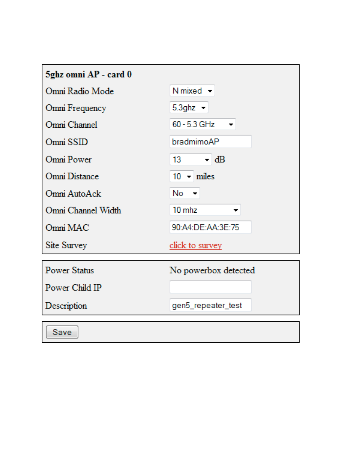
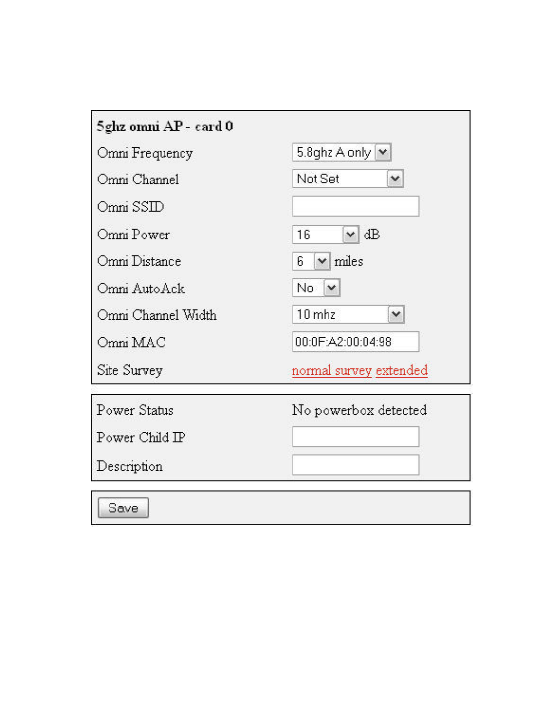
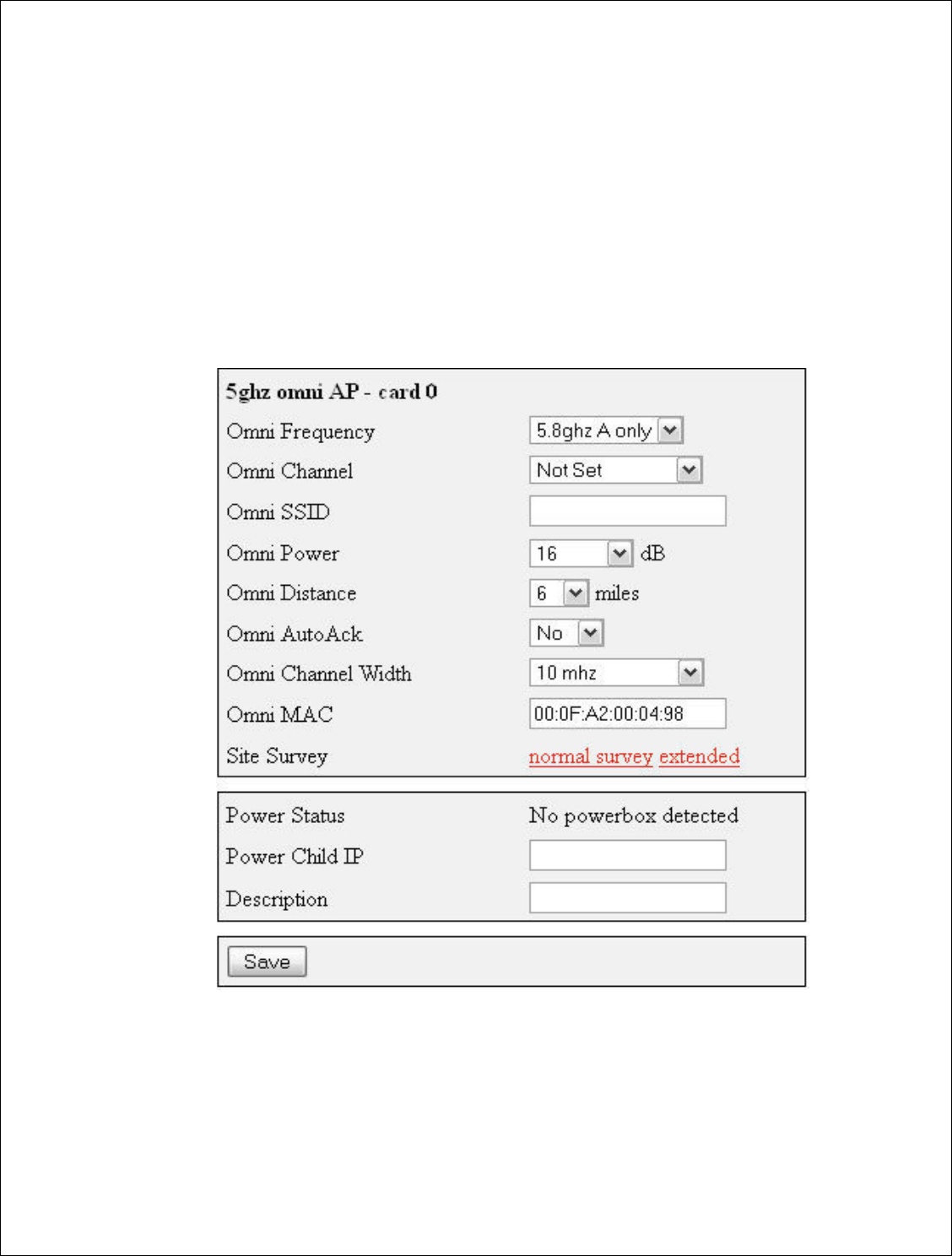
Configuring Card 0 (5 GHz Omni AP –Card 0)
Card 0 is normally where Point to multi point customers will connect through.
Now we will need to configure the 5 GHz Omni. If you are replacing the
device the channel, channel width and mac are very important. All three
values connect CPEs to the 5 GHz Omni. More information on the fields is
listed below.
27 | P a g e
DigitalPath, Inc. 275 Airpark Boulevard, Suite 500, Chico, CA 95973 | 800-676-PATH |www.digitalpath.net
CONFIDENTIAL © 2000-2012 DigitalPath, Inc. All rights reserved
Omni frequency: This is the wireless mode that the 5 GHz Omni will run on.
This can be either 5.3 GHz A only , 5.5 GHz A only or 5.8 A only.
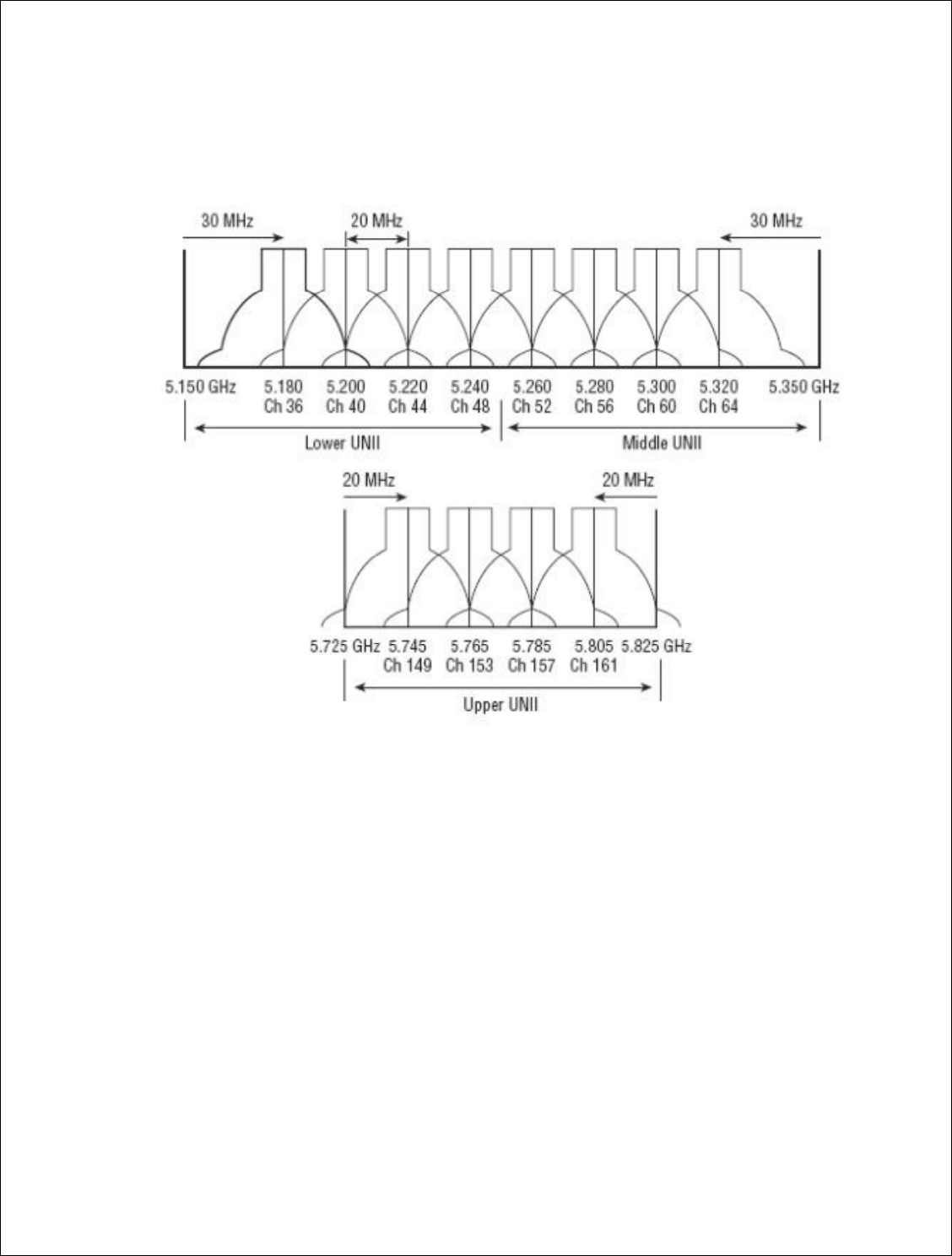
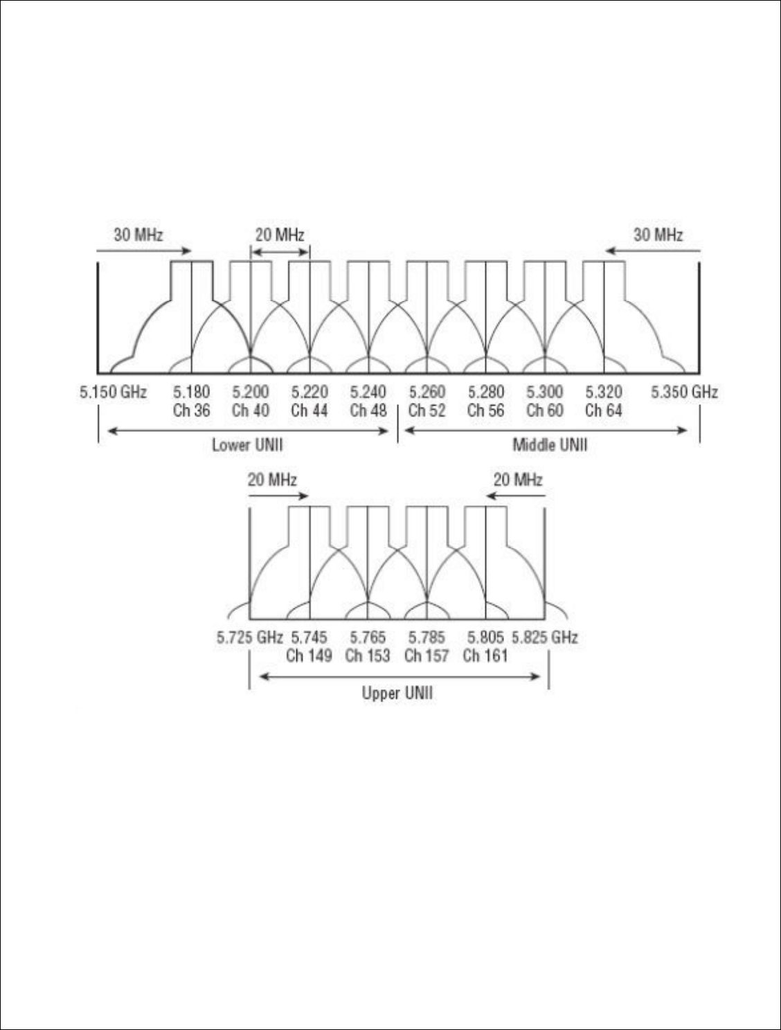
Omni Channel: This is the wireless channel the radio will broadcast on. See
graph below for overlapping channels.
Omni SSID: The Omni SSID should contain a short description of the unit.
Omni Power: This is the transmit power the radio will broadcast at. Please
see the transmit power table located in the FCC section of this document for
the proper self-installation transmit power for your antenna/device.
Omni Distance: This is the Ack time out settings. This should be an
approximation of the mileage of the link.
Omni AutoAck: Is a program that tests how many errors on each acktmout
settings occurs and will manipulate it-self to the correct ack time out settings
with the least errors.

28 | P a g e
DigitalPath, Inc. 275 Airpark Boulevard, Suite 500, Chico, CA 95973 | 800-676-PATH |www.digitalpath.net
CONFIDENTIAL © 2000-2012 DigitalPath, Inc. All rights reserved
Omni Channel Width: uses 10 and 20 MHz transmit channel widths.
Omni Mac: The Omni mac address is the mac address CPEs will connect to.
This may need to be cloned if you are replacing a device.
Site Survey: Will survey all available wireless devices in the area. An
extended survey will show you more devices and will survey longer. An
extended survey is recommended when trying to find wireless devices.
Description: This is the site location.
29 | P a g e
DigitalPath, Inc. 275 Airpark Boulevar
CONFIDENTIAL
© 2000
Identifying Types of Rep
Digitalpath uses man
here are some examp
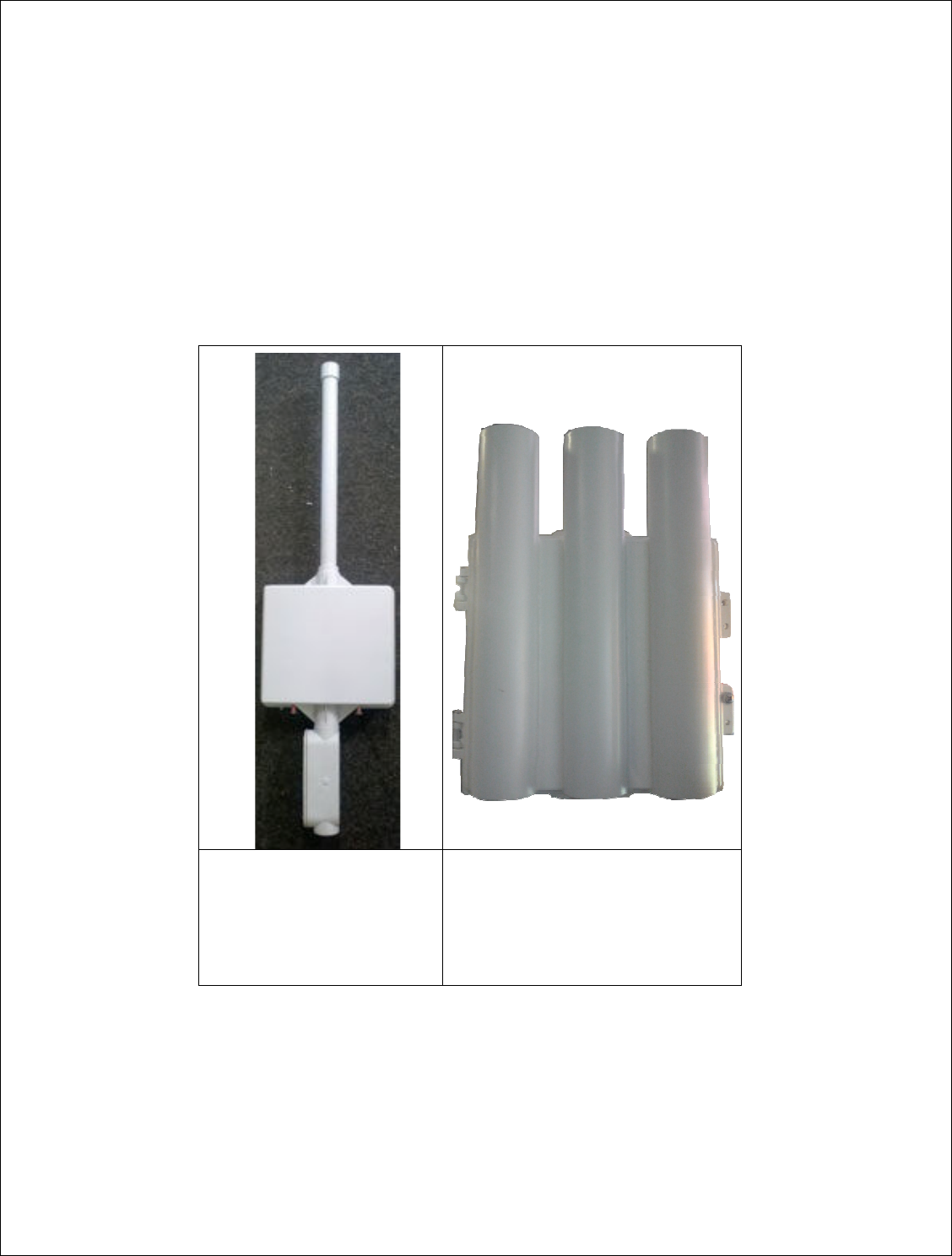
G5RL10
Repe
5 GHZ omni
(1
5GHZ Panel
(1
Optional Exte
Connectors
inst
omni
(G5RL1
levard, Suite 500, C
hico, CA 95973 | 800-676-
PATH |ww
2000
-2012
DigitalPath, Inc. All rights reserved
f Repeaters and Antennas
many different types of repeater and antenna co
xamples
.
Repeater
(10dBi)
(18dBi)
External
instead of
5RL10E)
Trisector
5 GHZ omni
5GHZ Panel 2 TX, 3 RX
Antennas
|www.digitalpath.net
ved
na combinations
30 | P a g e
DigitalPath, Inc. 275 Airpark Boulevard, Suite 500, Chico, CA 95973 | 800-676-PATH |www.digitalpath.net
CONFIDENTIAL © 2000-2012 DigitalPath, Inc. All rights reserved
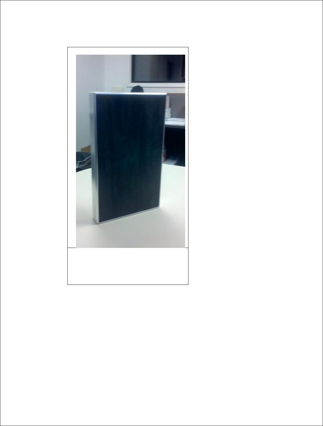
Duo
-
Sector
Dual 5GHz 17dBi antenna

31 | P a g e
DigitalPath, Inc. 275 Airpark Boulevard, Suite 500, Chico, CA 95973 | 800-676-PATH |www.digitalpath.net
CONFIDENTIAL © 2000-2012 DigitalPath, Inc. All rights reserved
PRODUCT CODE
DESCRIPTION
G5RL10 5GHz Panel (18dBi) w/ integrated 10dBi Omni Directional Antenna
G5RL10E 5GHz Panel w/ external connectors
G5RL10G 5GHz Panel (18dBi) w/ integrated 10dBi Omni Directional Antenna
w/ GPS
G5RL10EG 5GHz Panel w/ external connectors w/ GPS
G5RL10T 5GHz Tri-Sector (17dBi)
G5RL10TG 5GHz Tri-Sector (17dBi) w/ GPS
G5RL10TH 5GHz Tri-Sector (17dBi) w/ 48v Heater
G5RL10THG 5GHz Tri-Sector (17dBi) w/ GPS and 48v Heater
G5RL10TS 5GHz Tri-Sector (17dBi) w/ shims
G5RL10TGS 5GHz Tri-Sector (17dBi) w/ GPS and shims
G5RL10THS 5GHz Tri-Sector (17dBi) w/ 48v heater / shims
G5RL10TGHS 5GHz Tri-Sector (17dBi) w/ GPS / 48v heater / shims
G5RL102XG 5GHz Duo-Sector (17dBi) w/ GPS and aluminum case
G5RL102X 5GHz Duo-Sector (17dBi) w/ aluminum case
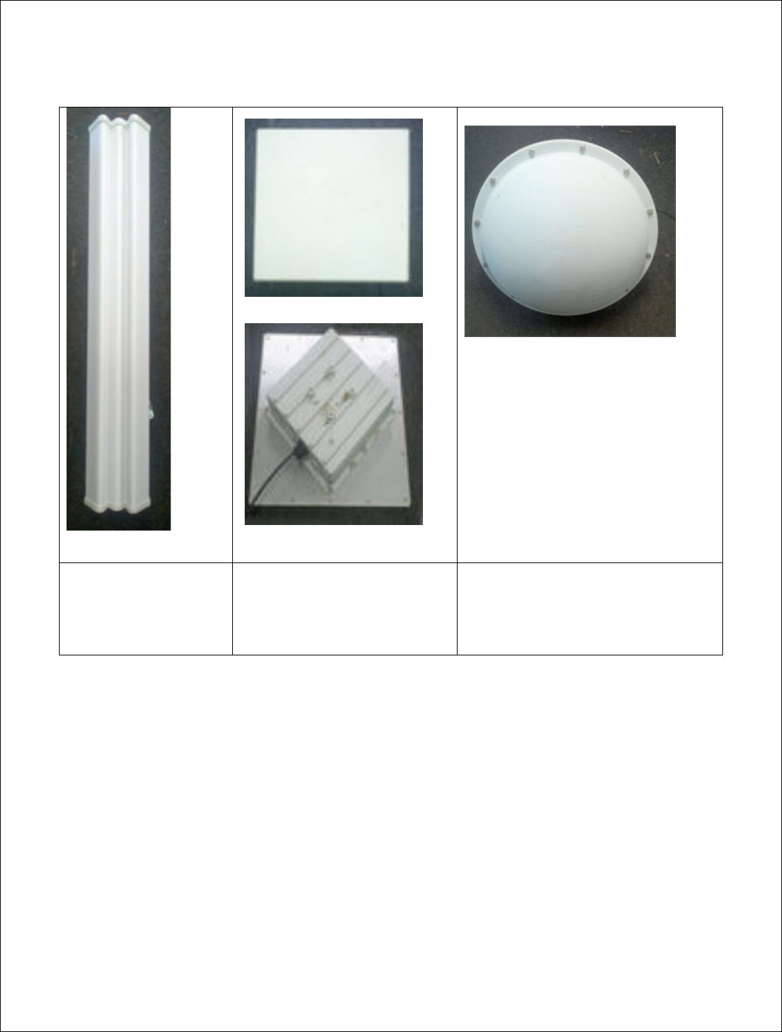
External Antennas
There are a couple different types of external antennas Digitalpath uses. Here
are some examples.
5GHZ 20dBi Dual Polarity Sector - These are dual polarity sectors. Uses
a RP-SMA cable listed in the parts list at the end of this document.
5GHZ 23dBi External Diamond –These can be used to improve signal or
create another downlink device. Should be used on PTP links.
32 | P a g e
DigitalPath, Inc. 275 Airpark Boulevard, Suite 500, Chico, CA 95973 | 800-676-PATH |www.digitalpath.net
CONFIDENTIAL © 2000-2012 DigitalPath, Inc. All rights reserved
5GHZ 2ft 29db Dish – Dishes are used for longer distance links. They give
you a 15 degree beam width. Dishes can be installed on any external 5 GHz
port. Point to Point links only.
5GHZ Sector
Dual Polarity
20dbi Gain
5ghz External Diamond
Single Polarity Vertical
23dbi Gain
5ghz External Dish
Single polarity Vertical
2 ft 29dbi Gain
Optional 33dbi Dish
33 | P a g e
DigitalPath, Inc. 275 Airpark Boulevar
CONFIDENTIAL
© 2000
Understanding the Statu
The Gen 5
Repeater’s
are the definitions an
Understanding the Gener
Description:
This is
page. Usually will be
Router IP:
This is th
Client IP:
This is the
Mode:
This is the cu
levard, Suite 500, C
hico, CA 95973 | 800-676-
PATH |ww
2000
-2012
DigitalPath, Inc. All rights reserved
tatus Page
ater’s status page has some general useful infor
s and examples of the status page.
eneral Tab
is is the description entered at the bottom of th
ll be the
site locations address.
is the Routing IP address for the AP router
is the Bridged IP on a
n AP router
e current Mode the repeater is running in.
|www.digitalpath.net
ved
information. Here
of the settings

34 | P a g e
DigitalPath, Inc. 275 Airpark Boulevard, Suite 500, Chico, CA 95973 | 800-676-PATH |www.digitalpath.net
CONFIDENTIAL © 2000-2012 DigitalPath, Inc. All rights reserved
Device Type: Displays the Generation of the Repeater.
Software version: Shows current software version. Installers need to take
note of this when replacing repeaters; firmware needs to be on the newest
current version.
Interfaces: Shows current software version. Installers need to take note of
this when replacing repeaters; firmware needs to be on the newest current
version.
35 | P a g e
DigitalPath, Inc. 275 Airpark Boulevar
CONFIDENTIAL
© 2000
Understanding
and us
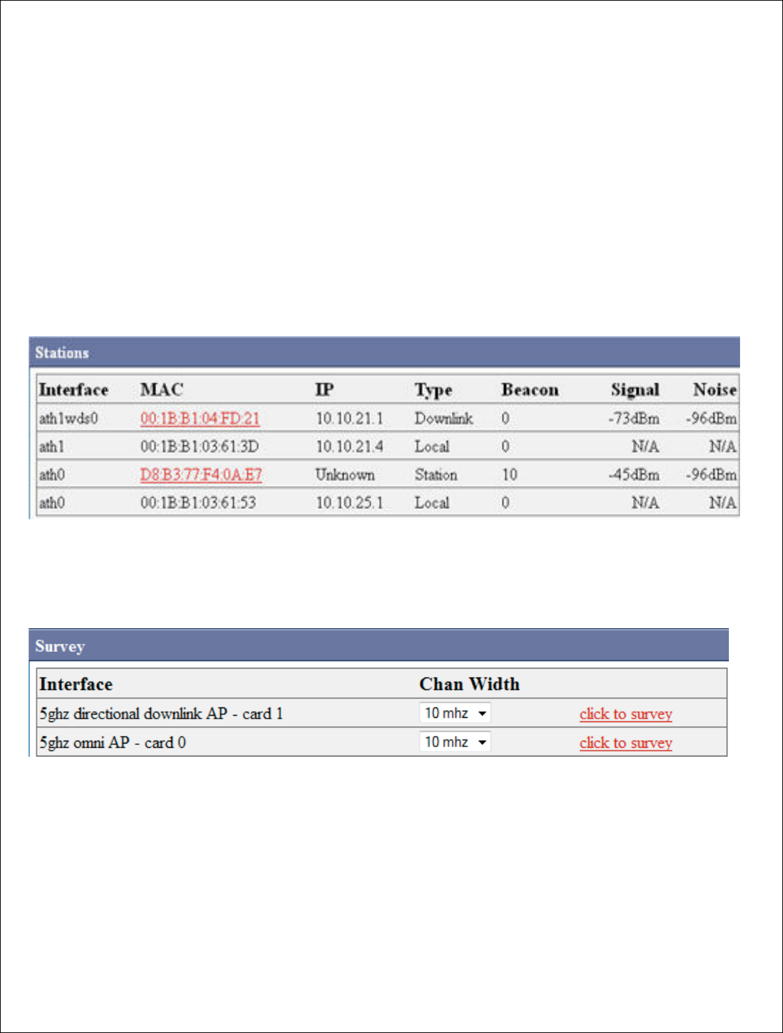
The stations tab displ
troubleshooting.
Page
check.
Stations-
Displays a
own Downlink, local i
Also shows signal
stre
Survey -
The Survey
and in different chann
Settings page.
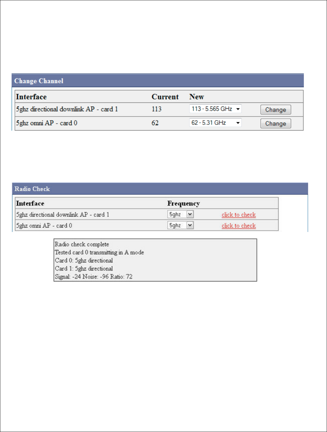
Change Channel
-
change channel sectio
there the repeater se
change the channel. A
goes forward with its
levard, Suite 500, C
hico, CA 95973 | 800-676-
PATH |ww
2000
-2012
DigitalPath, Inc. All rights reserved
d using the
Stations tab
displays current wireless information and tools f
Pages such as Stations, Survey, Change channe
ys all current local and associated hosts. It will
cal interfaces, and stations connected on what
strengths and noise floors.
rvey tap gives you the option
from surveying in
hannel widths. This can also be completed in Co
-
To change channel properly it needs to be d
section of the Stations tab. By doing the channe
er sends out a beacon to its children that it is go
nel. After the repeater sends out the bea
con to
h its channel change. This is important when ch
|www.digitalpath.net
ved
ols for
annel, and radio
will
display its
hat interface.
ng in each radio
in Configure >
be done in the
annel change
is going to
n to its children it
en changing
36 | P a g e
DigitalPath, Inc. 275 Airpark Boulevar
CONFIDENTIAL
© 2000
channels because wit
following frequency c
Radio Check -
Radio
radio working properl
your radio results. If
DHCP-
Displays the l
until their lease expir
levard, Suite 500, C
hico, CA 95973 | 800-676-
PATH |ww
2000
-2012
DigitalPath, Inc. All rights reserved
e without
the beacon you can find CPEs
and rep
cy changes.
Radio Check is a simply program that checks
to
operly. Just press click to check, and it will come
s. If no signal is determined the radio is bad.
the leases on the 10.
x.x.x Network to its CPE
s a
xpires.
|www.digitalpath.net
ved
repeaters not
to see if the
come up with
s and how long

37 | P a g e
DigitalPath, Inc. 275 Airpark Boulevard, Suite 500, Chico, CA 95973 | 800-676-PATH |www.digitalpath.net
CONFIDENTIAL © 2000-2012 DigitalPath, Inc. All rights reserved
Speed Test- This feature is not functional in the GUI. Please refer to the
SSH section of this manual.
38 | P a g e
DigitalPath, Inc. 275 Airpark Boulevar
CONFIDENTIAL
© 2000
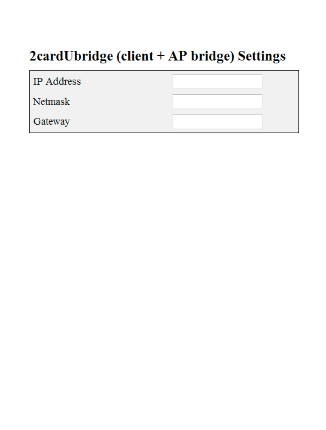
Configuring a Uplink
Bri
1.
After logging into the rel
2cardUbri
dge(client + AP
2.
After choosing the mode
redirect you to the Config
bridge is finding a unuse
levard, Suite 500, C
hico, CA 95973 | 800-676-
PATH |ww
2000
-2012
DigitalPath, Inc. All rights reserved
Bridge
e relay go to Configure > Mode. Next, choose
+ AP Bridge
)
ode of the device to 2cardUBridge (client + AP
onfigure > Settings page. The first part of conf
nused bridged IP in the subnet you are connect
|www.digitalpath.net
ved
se
AP Bridge) it will
configuring a
nect to
.
39 | P a g e
DigitalPath, Inc. 275 Airpark Boulevar
CONFIDENTIAL
© 2000
IP Address
: The brid
bridge group.
Netmask:
This field
contains.
Gateway:
This field
mode it will
be the ga
levard, Suite 500, C
hico, CA 95973 | 800-676-
PATH |ww
2000
-2012
DigitalPath, Inc. All rights reserved
e bridged IP address connecting the two sites on
field represents the subnet that the br1 bridge g
field represents your gateway from this device.
e gateway of the router in your br1 bridge grou
|www.digitalpath.net
ved
es on the br1
ge group
ice. In a router
group IP address.
40 | P a g e
DigitalPath, Inc. 275 Airpark Boulevard, Suite 500, Chico, CA 95973 | 800-676-PATH |www.digitalpath.net
CONFIDENTIAL © 2000-2012 DigitalPath, Inc. All rights reserved
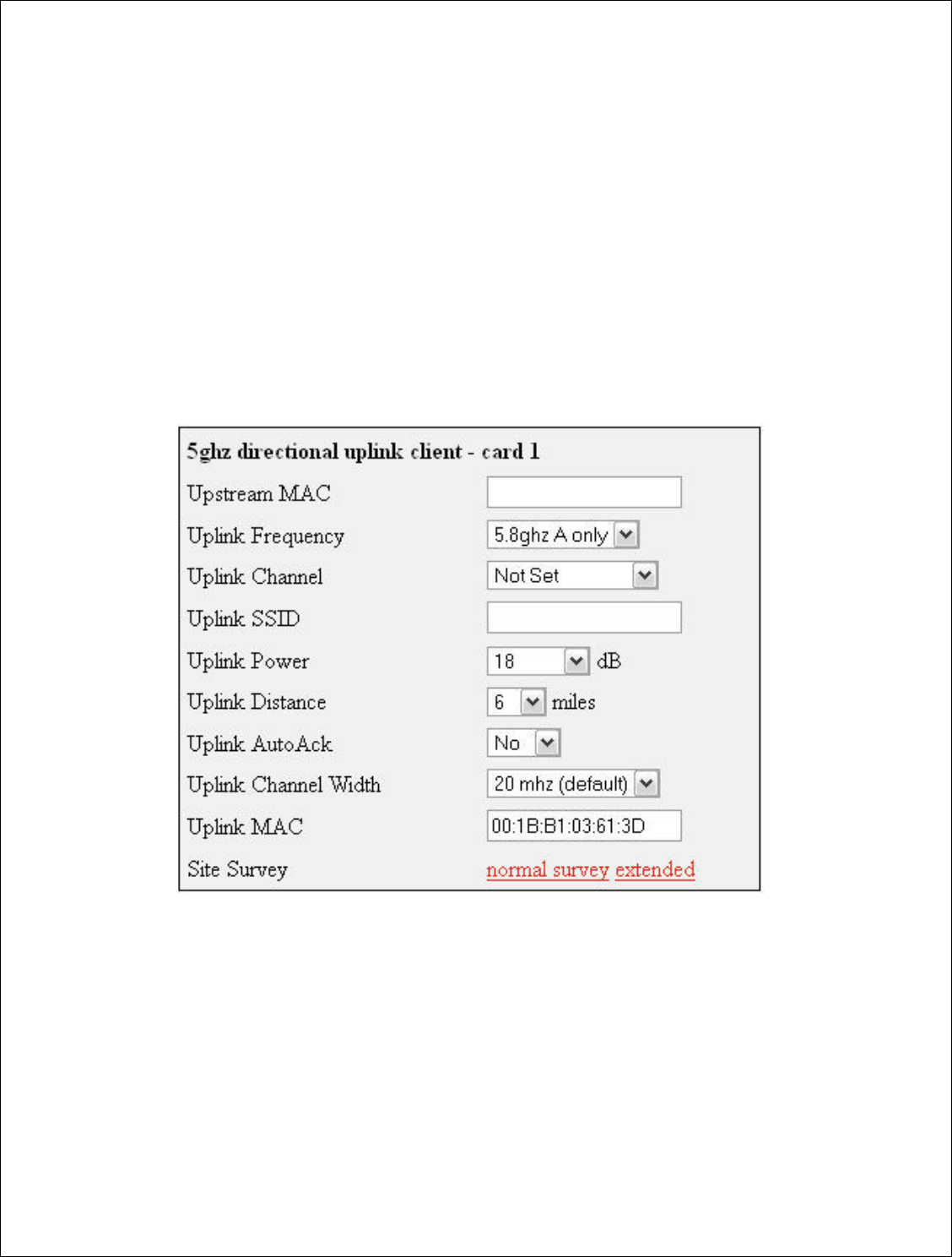
Configuring Card 1 (5 GHz directional uplink client –card 1)
Next, to connect the site we will need to do a survey from card 1 (5 GHz
directional uplink client). Scroll down to the site survey column and press
extended. This will survey for all available wireless device in the 5 GHz band.
After finding the appropriate downlink to connect to simply press the red link
labeled >select. This will enter the upstream Mac address, uplink frequency,
and uplink channel. You will have to put in a SSID of the sites name followed
by UL. Set the correct txpower and mileage. More information on the fields is
listed below.
Upstream MAC: This is the MAC address of the device the uplink will be
connecting to.
Uplink frequency: The current frequency band the radio will broadcast in.
5.3 GHz A only and 5.8 GHz A only.
Uplink channel: This will be dependent upon the uplink frequency field

41 | P a g e
DigitalPath, Inc. 275 Airpark Boulevard, Suite 500, Chico, CA 95973 | 800-676-PATH |www.digitalpath.net
CONFIDENTIAL © 2000-2012 DigitalPath, Inc. All rights reserved
Uplink SSID: It is helpful to set this field to something related to the
location of the device. There can be no spaces in the SSID (Example:
701MainstUL)
Uplink Power: This is the transmit power the radio will broadcast at. Please
talk to your supervisor about appropriate transmit power settings to abide by
FCC regulations.
Uplink Distance: This is the Ack time out setting that calculates how far to
send the data. Setting the distance to 10% longer than the actual distance
between repeaters is recommended.
Uplink AutoAck: Is a program that tests how many errors on each
acktmout settings occurs and will manipulate it-self to the correct ack time
out settings with the least errors.
*Only use this on far shots that are affected by speeds or duplicate packets
due to a fluctuating ack value.
Uplink Channel Width: Channel width can be set to 20 MHz or 10 MHz.
This is the channel space the current frequency will broadcast at. 20 MHz will
give you more throughput and is recommended for infill, backhaul repeaters
and uplinks. 10 MHz is recommended for Point to multi point connections.
Uplink Mac: The uplink mac is one mac address that is associated to the
card1 br1 bridge group. This mac will never have to be cloned when replacing
devices.
Site Survey: Will survey all available wireless devices in the area. An
extended survey will show you more devices and will survey longer. An
extended survey is recommended when trying to find wireless devices.
42 | P a g e
DigitalPath, Inc. 275 Airpark Boulevar
CONFIDENTIAL
© 2000
Configuring Card 0
(
Card 0 is normally wh
Now we will need to c
device the channel, c
values connect
CPEs
listed below.
Omni frequency:
Th
run at. This can only
Omni Channel:
This
levard, Suite 500, C
hico, CA 95973 | 800-676-
PATH |ww
2000
-2012
DigitalPath, Inc. All rights reserved
(
5 GHz Omni AP –Card 0)
ly where Point to multi point customers will conn
d to configure the
5 GHz Omni
. If you are replac
el, channel width and mac are very
important. A
PEs
to the 5 GHz Omni.
More information on the
This
is the wireless mode that the 5 GHz
Om
only
be in B only mode.
This is the wireless channel.
|www.digitalpath.net
ved
connect through.
eplacing the
nt. All three
n the fields is
Omni
radio will

43 | P a g e
DigitalPath, Inc. 275 Airpark Boulevard, Suite 500, Chico, CA 95973 | 800-676-PATH |www.digitalpath.net
CONFIDENTIAL © 2000-2012 DigitalPath, Inc. All rights reserved
Omni SSID: This is the MAC address of the device the uplink will be
connecting to.
Omni Power: This is the transmit power the radio will broadcast at. See the
FCC section of this document for transmit power settings per antenna.
Omni Distance: This is the Ack time out settings.
Omni AutoAck: Is a program that tests how many errors on each acktmout
settings occurs and will manipulate it to the correct ack time out settings with
the least errors.
Omni Channel Width: 20 MHz and 10MHz channel widths are
recommended
Omni Mac: The Omni mac address is the mac address CPEs will connect to.
This may need to be cloned if you are replacing a device.
Site Survey: Will survey all available wireless devices in the area. An
extended survey will show you more devices and will survey longer. An
extended survey is recommended when trying to find wireless devices.
Power Child IP: This is used for devices that are daisy chained off of each
other. This field is normally not filled out. Nothing is affected if not filled out it
is just for reference.
Description: This is the site location.
44 | P a g e
DigitalPath, Inc. 275 Airpark Boulevard, Suite 500, Chico, CA 95973 | 800-676-PATH |www.digitalpath.net
CONFIDENTIAL © 2000-2012 DigitalPath, Inc. All rights reserved
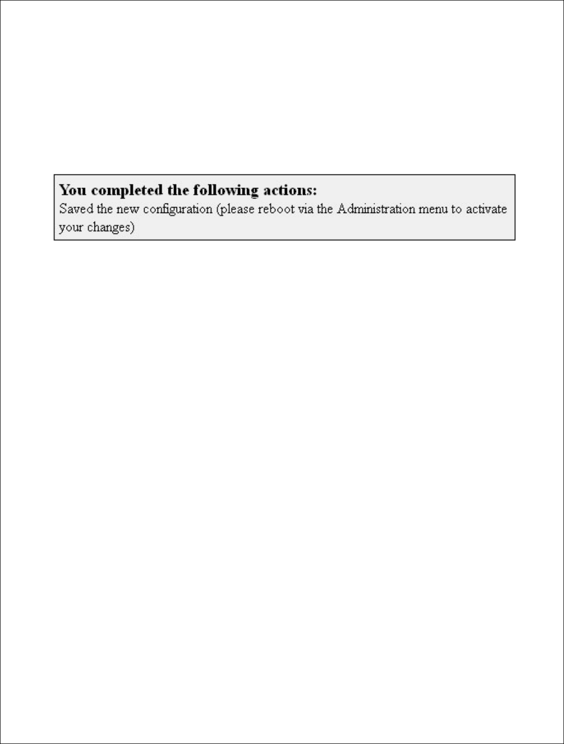
Saving and Rebooting
After configuring the device you will need to save the settings and reboot the
repeater. This is done by clicking save at the bottom of the page. You will
then get a prompt at the top of the page to go to Administration > Reboot.
45 | P a g e
DigitalPath, Inc. 275 Airpark Boulevard, Suite 500, Chico, CA 95973 | 800-676-PATH |www.digitalpath.net
CONFIDENTIAL © 2000-2012 DigitalPath, Inc. All rights reserved
Configuring a Downlink Bridge
After logging into the relay go to Configure > Mode then choose 2cardDBridge
(dual AP Bridge)
After choosing the mode of the device to 2cardDBridge (dual AP Bridge) it will
redirect you to the Configure > Settings page. The first part of configuring a bridge
is to know your IP address.
IP Address: This is the bridged IP address on the local subnet on the site the
repeater is being installed on.

46 | P a g e
DigitalPath, Inc. 275 Airpark Boulevard, Suite 500, Chico, CA 95973 | 800-676-PATH |www.digitalpath.net
CONFIDENTIAL © 2000-2012 DigitalPath, Inc. All rights reserved
*It is important that the data cable be plugged into eth0 on the repeater or it will
not come online as a router.
Netmask: This is the local bridge groups subnet mask either being
announced on the switch or the uplink at the location.
Gateway: This is the Gateway of the local bridge group at the location.
Parent IP: this will either be the managed switch at the location or the
uplink at the site. This is important since the parent ping watchdog will ping
this address.
47 | P a g e
DigitalPath, Inc. 275 Airpark Boulevard, Suite 500, Chico, CA 95973 | 800-676-PATH |www.digitalpath.net
CONFIDENTIAL © 2000-2012 DigitalPath, Inc. All rights reserved
Configuring Card 1 (directional downlink AP- card 1)
Downlink Frequency: This is the frequency band the radio will broadcast
in.
Downlink Channel: This will be a downlink channel that will feed either a
relay or Point to multi point customers. When choosing a channel use a
channel that is not used on the site and is at least 4 channels away from any
frequency used on the site.
Downlink SSID: Use a SSID that is appropriately labeled.
Downlink Power: This is the transmit power the radio will broadcast at.
Please talk to your supervisor about appropriate transmit power settings.
Downlink Distance: This is the Ack time out settings that calculate how far
to send the data. Setting the distance to 10% longer than the actual distance
between repeaters is recommended. If it is an internal panel antenna the
longest distance it can broadcast is 10mi.

48 | P a g e
DigitalPath, Inc. 275 Airpark Boulevard, Suite 500, Chico, CA 95973 | 800-676-PATH |www.digitalpath.net
CONFIDENTIAL © 2000-2012 DigitalPath, Inc. All rights reserved
Downlink AutoAck: Is a program that tests how many errors on each
acktmout settings occurs and will manipulate itself to the correct ack time out
settings with the least errors.
*Only use this on far shots that are affected by speeds or duplicate
packets due to a fluctuating ack value.
Downlink Channel Width: Chanel width can be set to 20 MHz or 10 MHz.
This is the channel space the current frequency will broadcast at.
Downlink Mac: The downlink mac is the mac address either relays or CPEs
will connect to. If replacing the device this mac address will need to be
cloned.
Site Survey: Will survey all available wireless devices in the area. An
extended survey will show you more devices and will survey longer. An
extended survey is recommended when trying to find wireless devices.
49 | P a g e
DigitalPath, Inc. 275 Airpark Boulevard, Suite 500, Chico, CA 95973 | 800-676-PATH |www.digitalpath.net
CONFIDENTIAL © 2000-2012 DigitalPath, Inc. All rights reserved
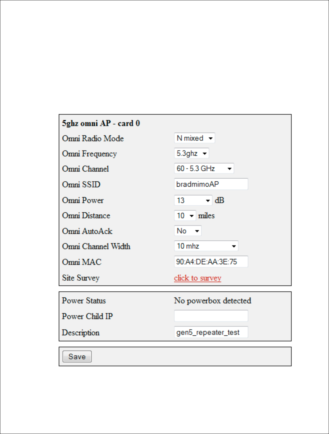
Configuring Card 0 (5 GHz Omni AP –Card 0)
Card 0 is normally where Point to multi point customers will connect through.
Now we will need to configure the 5 GHz Omni. If you are replacing the
device the channel, channel width and mac are very important. All three
values connect CPEs to the 5 GHz Omni. More information on the fields is
listed below.
Omni frequency: This is the wireless mode that the 5 GHz Omni will run on.
This can be either 5.3 GHz A only or 5.8 A only.
Omni Channel: This is the wireless channel the radio will broadcast on. See
graph below for overlapping channels.
50 | P a g e
DigitalPath, Inc. 275 Airpark Boulevard, Suite 500, Chico, CA 95973 | 800-676-PATH |www.digitalpath.net
CONFIDENTIAL © 2000-2012 DigitalPath, Inc. All rights reserved
Omni SSID: pick a name for this repeater to broadcast. No spaces.
Omni Power: This is the transmit power the radio will broadcast at. Please
talk to your supervisor about appropriate transmit power settings.
Omni Distance: This is the Ack time out settings. All 5 GHz Omnis are set to
6 miles. If it is a 5 GHz sector it needs to be set to 20mi. If it is a 5 GHz
diamond it can go up to 13- 15mi depending on the gain of the receiving
antenna.
Omni AutoAck: Is a program that tests how many errors on each acktmout
settings occurs and will manipulate it-self to the correct ack time out settings
with the least errors.
Omni Channel Width: 10 to 20 MHz channel widths are recommended.

51 | P a g e
DigitalPath, Inc. 275 Airpark Boulevard, Suite 500, Chico, CA 95973 | 800-676-PATH |www.digitalpath.net
CONFIDENTIAL © 2000-2012 DigitalPath, Inc. All rights reserved
Omni Mac: The Omni mac address is the mac address CPEs will connect to.
This may need to be cloned if you are replacing a device.
Site Survey: Will survey all available wireless devices in the area. An
extended survey will show you more devices and will survey longer. An
extended survey is recommended when trying to find wireless devices.
Description: This is the site location.
52 | P a g e
DigitalPath, Inc. 275 Airpark Boulevar
CONFIDENTIAL
© 2000
Understanding the Confi
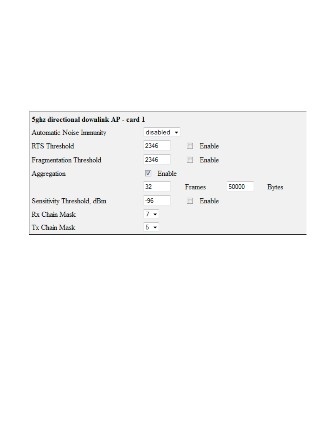
Understanding the Advan
The advanced tab ha
issues with wireless n
Automatic Noise Im
errors are too great o
the performance of th
make it more sensitiv
RTS Threshold:
RT
RF p
rotocol issue to a
Fragmentation Thr
without fragmenting
Aggregation:
Defin
frames or amount of
Rx Chain Mask:
Sta
Sector configuration
levard, Suite 500, C
hico, CA 95973 | 800-676-
PATH |ww
2000
-2012
DigitalPath, Inc. All rights reserved
onfigure
Page
dvanced Tab
b has a couple of features that can be used whe
ess noise or Ethernet related issues.
se Immunity
(ANI):
ANI turns off fy error rep
eat on a radio is will spike cpuload, whic
h in turn
of the radio. With ANI on the radio will ignore e
sitive to rx packets.
This can be turned on a pe
RTS (Request To Send) controls what size dat
to a RTS packet. The default is 2346.
Threshold:
The maximum frame size that can
ting the frame.
Defines how frames are aggregated together, ei
t of bytes. Whatever co
mes first.
Standard Rx Chain Mask is 5
for all devices ex
tion
.
|www.digitalpath.net
ved
when having
r reporting. If
turn will lower
ore errors and
a per radio basis.
e data packets the
t can be sent
r, either by
es except Tri
-
53 | P a g e
DigitalPath, Inc. 275 Airpark Boulevard, Suite 500, Chico, CA 95973 | 800-676-PATH |www.digitalpath.net
CONFIDENTIAL © 2000-2012 DigitalPath, Inc. All rights reserved
Tx Chain Mask: Standard Tx Chain Mask is 5.
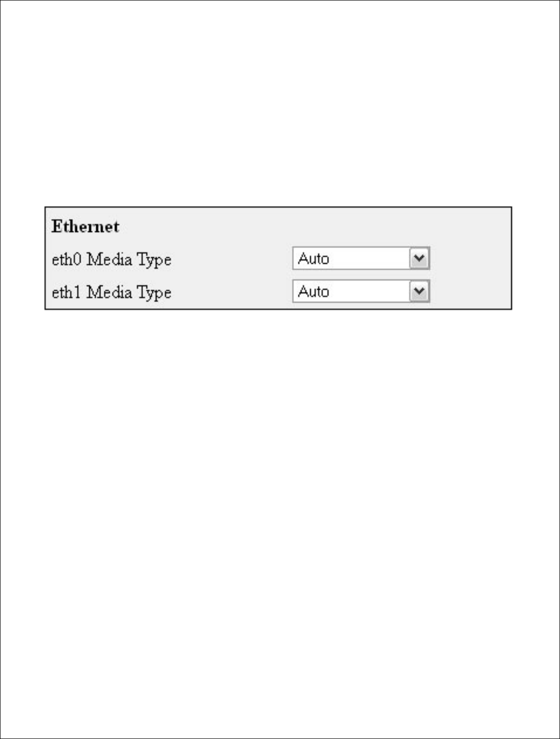
Ethernet: The Ethernet setting allows you to manipulate the negotiation of
Ethernet. When set to Auto Ethernet will auto-negotiate. Normally in most
situations this is the recommended value. If problems occur where packet
loss is happening between Ethernet ports through cabling, modifying these
settings can confirm a Ethernet related issue.
54 | P a g e
DigitalPath, Inc. 275 Airpark Boulevard, Suite 500, Chico, CA 95973 | 800-676-PATH |www.digitalpath.net
CONFIDENTIAL © 2000-2012 DigitalPath, Inc. All rights reserved
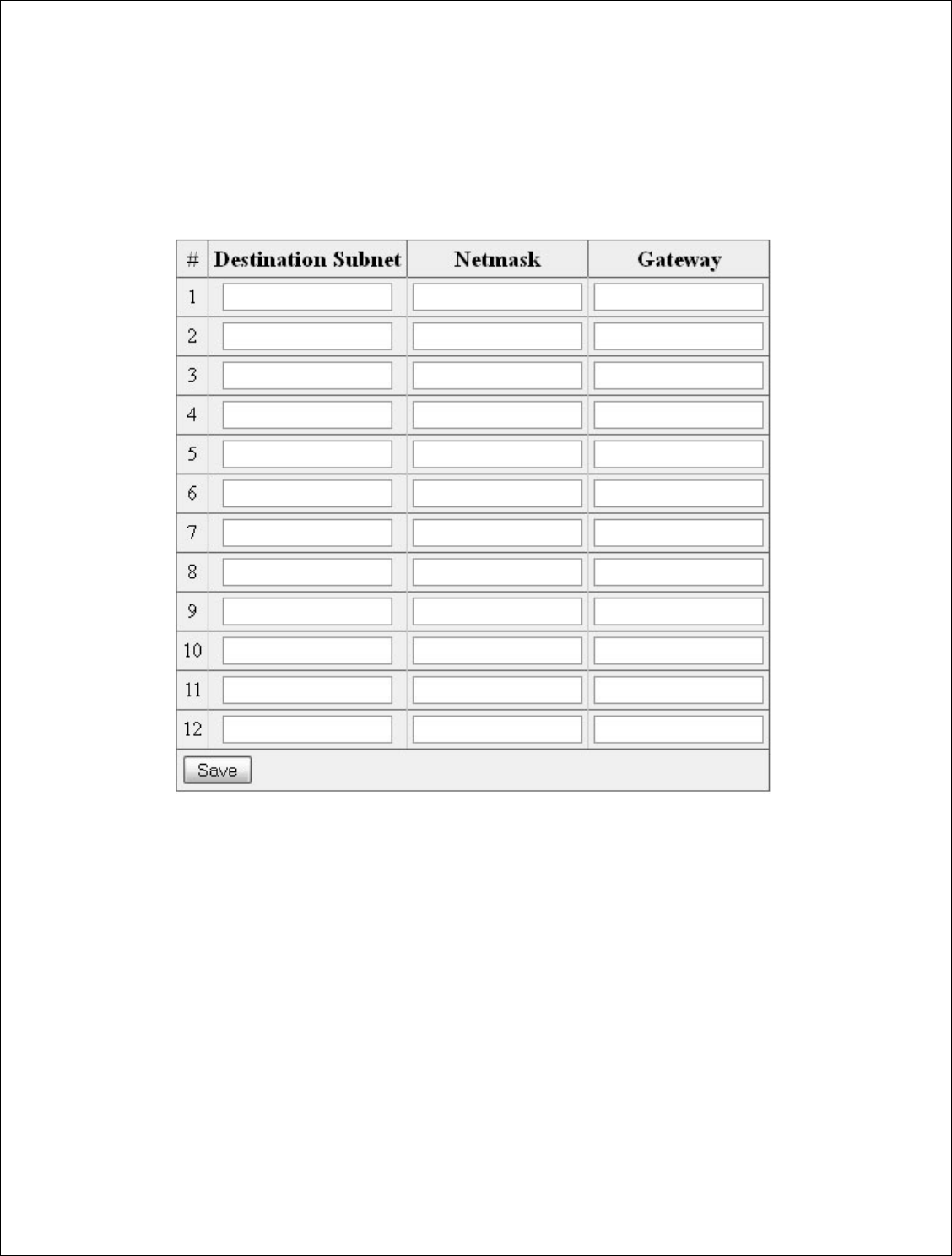
Understanding the Routes Tab
The routes tab is for manually configuring static routes.
55 | P a g e
DigitalPath, Inc. 275 Airpark Boulevar
CONFIDENTIAL
© 2000
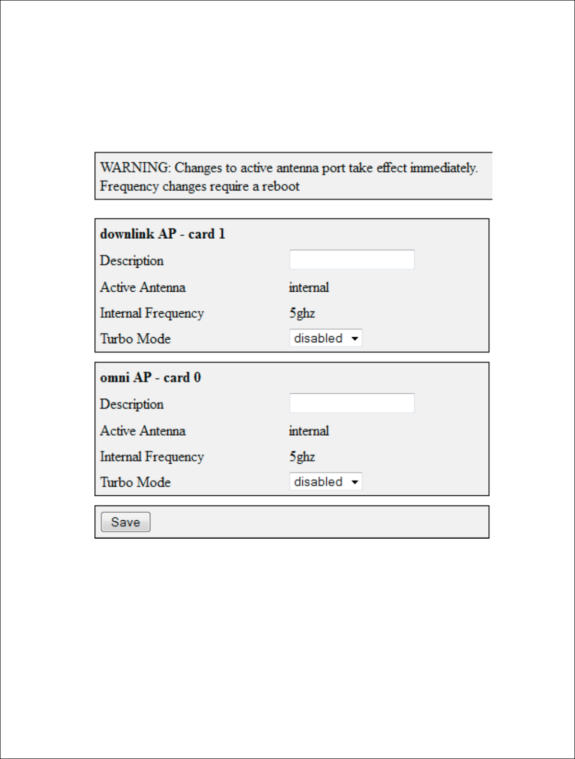
Understanding the
Anten
The antennas tab is f
on.
Description:
This ne
port. If on card 1 you
diamond in the descr
information on what i
Active Antenna:
Ei
external for an extern
Intern
al Frequency
levard, Suite 500, C
hico, CA 95973 | 800-676-
PATH |ww
2000
-2012
DigitalPath, Inc. All rights reserved
ntennas Tab
b is for configuring external devices and the freq
is needs to be labeled on what is connected to
you install a 23db external diamond, type in ex
escr
iption field. This will give installers and tech
hat is installed on each repeater.
Either set this to internal for an internal radio
xternal radio source (external diamond).
ency
–
This is the internal frequency on the radi
|www.digitalpath.net
ved
frequency is runs
d to the external
in external
technicians the
radio source
or
radio.

56 | P a g e
DigitalPath, Inc. 275 Airpark Boulevard, Suite 500, Chico, CA 95973 | 800-676-PATH |www.digitalpath.net
CONFIDENTIAL © 2000-2012 DigitalPath, Inc. All rights reserved
Turbo Mode – (DISABLED) and not available on gen5 repeaters. May be
available in a future version of software pending FCC certification.
57 | P a g e
DigitalPath, Inc. 275 Airpark Boulevard, Suite 500, Chico, CA 95973 | 800-676-PATH |www.digitalpath.net
CONFIDENTIAL © 2000-2012 DigitalPath, Inc. All rights reserved
Understanding the Administration Page
The administration page is where management of the repeaters configuration
and initial setup are applied.
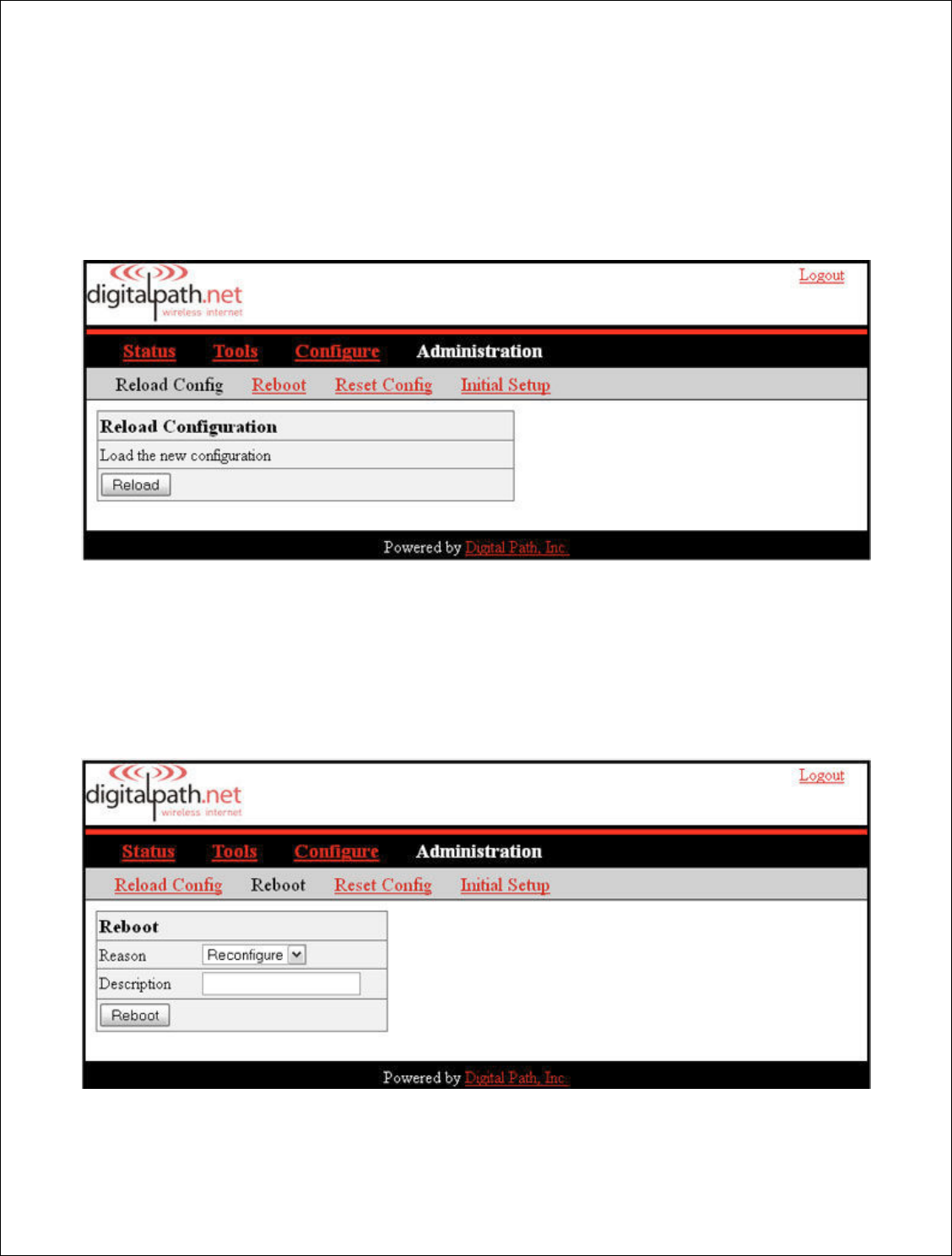
Reload Config: The reload config feature is disabled on Generation 5
repeaters.
Reboot: This will reboot the repeater. After rebooting the repeater you will
get a “device is rebooting prompt”. The screen will never change and you will
have to refresh the page to re-login to the device.

58 | P a g e
DigitalPath, Inc. 275 Airpark Boulevard, Suite 500, Chico, CA 95973 | 800-676-PATH |www.digitalpath.net
CONFIDENTIAL © 2000-2012 DigitalPath, Inc. All rights reserved
Reason: Choose either reconfigure, fix problem, or other. This will be listed
in the log as the type of reboot.
Description: The description is why you rebooted the devices e.g. Card 0
locked up.
Reset Config: The reset config tab will reset the device to its default
configuration. This should never be done remotely, only if an tech is at the
location.
Initial Setup: Manufacturing uses this to configure the settings for each
repeater type, configuration, and optional features. This may need to be
modified if any errors are made when setting up the device.
Hardware Details: Details what specific device the repeater is. Please see
Types of Repeaters
section above for more information.
5 GHz directional uplink client – card 1: Displays the mac address,
internal frequency setting and the ability to use either internal or external
antennae.
*If you need to set an external device on a radio and this setting only
displays internal you will need to edit the initial setup.
5 GHz Omni AP: Similar information as card 1.
*If you need to set an external device on a radio and these setting only
displays as internal you will need to edit the initial setup.
Eth0 Mac Address: displays the eth0 mac address. This mac address cannot be
edited or cloned.

59 | P a g e
DigitalPath, Inc. 275 Airpark Boulevard, Suite 500, Chico, CA 95973 | 800-676-PATH |www.digitalpath.net
CONFIDENTIAL © 2000-2012 DigitalPath, Inc. All rights reserved

60 | P a g e
DigitalPath, Inc. 275 Airpark Boulevard, Suite 500, Chico, CA 95973 | 800-676-PATH |www.digitalpath.net
CONFIDENTIAL © 2000-2012 DigitalPath, Inc. All rights reserved
FCC Compliance & Installation Statement
Definitions
15.3(h) Class A digital device. A digital device that is marketed for use in a
commercial, industrial or business environment, exclusive of a device which is
marketed for use by the general public or is intended to be used in the home.
15.3(i) Class B digital device. A digital device that is marketed for use in a
residential environment notwithstanding use in commercial, business and
industrial environments. Examples of such devices include, but are not
limited to, personal computers, calculators, and similar electronic devices that
are marketed for use by the general public.
Statement
This equipment has been tested and found to comply with the limits for a Class B
digital device, pursuant to part 15 of the FCC Rules. These limits are designed to
provide reasonable protection against harmful interference in a residential
installation. This equipment generates, uses and can radiate radio frequency
energy and, if not installed and used in accordance with the instructions, may
cause harmful interference to radio communications. However, there is no
guarantee that interference will not occur in a particular installation. If this
equipment does cause harmful interference to radio or television reception, which
can be determined by turning the equipment off and on, the user is encouraged
to try to correct the interference by one or more of the following measures:
— Reorient or relocate the receiving antenna.
— Increase the separation between the equipment and receiver.
— Connect the equipment into an outlet on a circuit different from that
to which the receiver is connected.
— Consult the dealer or an experienced radio/TV technician for help.
Attention
This device is intended for outdoor use only.

61 | P a g e
DigitalPath, Inc. 275 Airpark Boulevard, Suite 500, Chico, CA 95973 | 800-676-PATH |www.digitalpath.net
CONFIDENTIAL © 2000-2012 DigitalPath, Inc. All rights reserved
FCC statement 15.21(a)
Modifications not expressly approved by Digital Path, Inc could void your
authority to operate the equipment. Do not make modifications to the
equipment unless authorized by Digital Path, Inc.
FCC ID
Relay Point: RHK-G5RL10
Professional Installation
FCC statement 15.27(b)
This device should be professionally installed by a trained technician. The
installer shall be responsible for ensuring that the proper antenna is employed
to comply with FCC requirements. The equipment described herein may
only be used in accordance with accessories listed in below for FCC ID
numbers RHK-G5RL10.

62 | P a g e
DigitalPath, Inc. 275 Airpark Boulevard, Suite 500, Chico, CA 95973 | 800-676-PATH |www.digitalpath.net
CONFIDENTIAL © 2000-2012 DigitalPath, Inc. All rights reserved
Parts List & Tune-Up Information
External RF Cables for Connection to Modularized Connector Ports
This equipment must be professionally installed when utilizing modularized
connector ports.
SMA to RP-SMA Connector Cable PN # Hana Wireless CA-195 (3’) –HW-
CA195-SMAM-SMAM
- Used for Connecting to UBNT external sectors and Arc Wireless
Directional Panel
SMA to N-Connector Cable PN # Hana Wireless CA-185 (3’) - CA195-NM-
SMAM-3
- Used for Connecting to High Gain Arc Wireless 29 dBi and 33 dBi
antennas for 15.247 ISM
Ethernet Surge Suppression
Optional Ethernet/Power Surge Suppressor – Part # H-LS-001.01 –
DigitalPath, Inc
UL # 3VEO – Model DPISURG5E
Power Supply
Condor Electronics
Model: STD-2427P
Ferrites on power lead (QTY 2) – Steward 28A2024-0A0

63 | P a g e
DigitalPath, Inc. 275 Airpark Boulevard, Suite 500, Chico, CA 95973 | 800-676-PATH |www.digitalpath.net
CONFIDENTIAL © 2000-2012 DigitalPath, Inc. All rights reserved
Antenna
Each repeater has a combination of 1 or 2 antenna(s) present depending on
the configuration.
5GHz
UNII - 5250-5350 – 5500-5725 and ISM 5725-5850
Panel
ARCWireless Panel 23.0dBi
DPI – Internal 18.0dBi
Omni-Directional
UBNT (360 degree) 10.0 dBi
Sector
DPI (90 degree) 17.0 dBi
UBNT (90 degree) 17.0 dBi
UBNT (90-120 degree) 20.0 dBi
ISM 5.725-5850 MHz only
Dish
ARCWireless Dish 33.0 dBi
ARCWireless Dish 29.0 dBi
This equipment must be professionally installed when utilizing modularized
connector ports.
SMA to RP-SMA Connector Cable PN # Hana Wireless CA-195 (3’) –HW-
CA195-SMAM-SMAM
SMA to N-Connector Cable PN # Hana Wireless CA-185 (3’) - CA195-NM-
SMAM-3

64 | P a g e
DigitalPath, Inc. 275 Airpark Boulevard, Suite 500, Chico, CA 95973 | 800-676-PATH |www.digitalpath.net
CONFIDENTIAL © 2000-2012 DigitalPath, Inc. All rights reserved
Channels
Channel
Width
Lowest Channel
(MHz)
Highest Channel
(MHz)
15.247
5.725
-
5.85GHz Band
10MHz
5735
(147)
5840
(168)
20MHz
5740
(148)
5835
(167)
U
-
NII 5.25
-
5.35GHz Band
10MHz
5275
(55)
5325
(65)
20MHz
5280
(56)
5320
(64)
U
-
NII 5.47
-
5.725GHz
Band ** SEE BELOW FOR EXCLUSIONS
10MHz
5495
(99)
5705
(141)
20MHz
5500
(100)
5700
(140)
UNII 5.47-5.725 GHz Band Edge Channels
U
-
NII 5.47
-
5.
595
GHz
10MHz
5495
(99)
5595 (119)
20MHz
5500 (100)
5
590 (118)
UNII 5.47-5.725 GHz Band Edge Channels
U
-
NII 5.655
-
5.725GHz
10MHz
5655 (131)
5705
(141)
20MHz
5660 (132)
5700
(140)
Note: channels 5600-5650 (120-130) are excluded from the channel list.
All other antennas tested for FCC certification come manufactured with the
directional panel antenna and Omni directional antennas within the enclosure.

65 | P a g e
DigitalPath, Inc. 275 Airpark Boulevard, Suite 500, Chico, CA 95973 | 800-676-PATH |www.digitalpath.net
CONFIDENTIAL © 2000-2012 DigitalPath, Inc. All rights reserved
Notice of FCC power compliance for transmit power settings
Below is information related to dynamic frequency selection and power
settings per band specific to the antenna(s) you are using.
DFS and TDWR
Terminal Dopper Weather Radar uses the 5600-5650 MHz band for generating high
definition severe thunderstorm warnings. There are several of these sites throughout
the United States. If you are within 35 kilometers of a TDWR station you must be at
least 30 MHz center-to-center from the TDWR operating frequency for both client and
base station equipment. Table of the current TDWR can be found in the FCC document
“ 443999 Do1 Approval of DFS UNII Devices v01” from OET located at the URL below.
https://apps.fcc.gov/kdb/GetAttachment.html?id=dV24P2kaxB%2BkKzIPZxHxHg%3D%
3D
The original bulletin is also attached to the end of this manual for reference.
Professional Installation Transmit Power Settings Tables
Antenna type, channel width and frequency band specified. On two card radio devices,
each radio must be in a different band (e.g. 5.3, 5.5, 5.8 GHz). DFS (Dynamic
Frequency Selection) is enabled for the 5250-5350, 5470-5725. The 5725-5850 band is
ISM 15.247 and does not require DFS.
For the frequencies/antennas and channel widths listed below, it is advised that you
utilize the lowest transmit power for the particular band/modulation/channel width if
you are unsure about what modulation scheme you want to run.

66 | P a g e
DigitalPath, Inc. 275 Airpark Boulevard, Suite 500, Chico, CA 95973 | 800-676-PATH |www.digitalpath.net
CONFIDENTIAL © 2000-2012 DigitalPath, Inc. All rights reserved
5GHz Omni (10
dBi)
–
UBNT AMO
-
5G10
5250 MHz – 5350 MHz
Freq: 5275 MHz (low), 5300MHz (mid), 5325MHz
(high)
Channel Bandwidth: 10MHz
802.11a: TX power setting = 17.5, 17.5, 17.5
802.11n: TX power setting = 17.5, 17.5, 17.5
Freq: 5280MHz (low), 5300MHz (mid), 5320MHz
(high)
Channel Bandwidth: 20MHz
802.11a: TX power setting = 19, 19, 18
802.11n: TX power setting = 19, 19, 18
5470 MHz – 5725 MHz
5495MHz, 5590MHz, 5705MHz
Channel Bandwidth: 10MHz
802.11a: TX power setting = 17.5, 18.5, 18.5
802.11n: TX power setting = 17, 18.5, 17.5
5500MHz, 5590MHz, 5700MHz
Channel Bandwidth: 20MHz
802.11a: TX power setting = 17.5, 19, 16.5
802.11n: TX power setting = 16.5, 19, 16.5
5725 MHz - -5850 MHz
5735MHz, 5785MHz, 5840MHz
Channel Bandwidth: 10MHz
802.11a: TX power setting = 16,16,16
802.11n: TX power setting = 16,16,16
5740MHz, 5785MHz, 5835MHz
Channel Bandwidth: 20MHz
802.11a: TX power setting = 16,16,16
802.11n: TX power setting = 16,16,16

67 | P a g e
DigitalPath, Inc. 275 Airpark Boulevard, Suite 500, Chico, CA 95973 | 800-676-PATH |www.digitalpath.net
CONFIDENTIAL © 2000-2012 DigitalPath, Inc. All rights reserved
5GHz Panel (18
dBi)
5250 MHz – 5350 MHz
Freq: 5275 MHz (low), 5300MHz (mid), 5325MHz
(high)
Channel Bandwidth: 10MHz
802.11a: TX power setting = 10,10,10
802.11n: TX power setting = 10,10,10
Freq: 5280MHz (low), 5300MHz (mid), 5320MHz
(high)
Channel Bandwidth: 20MHz
802.11a: TX power setting = 12.5,12.5,12.5
802.11n: TX power setting = 12.5,12.5,12.5
5470 MHz – 5725 MHz
5495MHz, 5590MHz, 5705MHz
Channel Bandwidth: 10MHz
802.11a: TX power setting = 11,11,11
802.11n: TX power setting = 11,11,11
5500MHz, 5590MHz, 5700MHz
Channel Bandwidth: 20MHz
802.11a: TX power setting = 13.5,13.5,12.5
802.11n: TX power setting = 13.5,13.5,11
5725 MHz - -5850 MHz
5735MHz, 5785MHz, 5840MHz
Channel Bandwidth: 10MHz
802.11a: TX power setting = 14.5,14.5,14.5
802.11n: TX power setting = 14.5,14.5,14.5
5740MHz, 5785MHz, 5835MHz
Channel Bandwidth: 20MHz
802.11a: TX power setting = 14.5,14.5,14.5
802.11n: TX power setting = 14.5,14.5,14.5

68 | P a g e
DigitalPath, Inc. 275 Airpark Boulevard, Suite 500, Chico, CA 95973 | 800-676-PATH |www.digitalpath.net
CONFIDENTIAL © 2000-2012 DigitalPath, Inc. All rights reserved
5GHz Sector (20
dBi)
5250 MHz – 5350 MHz
Freq: 5275 MHz (low), 5300MHz (mid), 5325MHz
(high)
Channel Bandwidth: 10MHz
802.11a: TX power setting = 10.5,10.5,10.5
802.11n: TX power setting = 10.5,10.5,10.5
Freq: 5280MHz (low), 5300MHz (mid), 5320MHz
(high)
Channel Bandwidth: 20MHz
802.11a: TX power setting = 10.5,10.5,10.5
802.11n: TX power setting = 10.5,10.5,10.5
5470 MHz – 5725 MHz
5495MHz, 5590MHz, 5705MHz
Channel Bandwidth: 10MHz
802.11a: TX power setting = 11.5,11.5,11.5
802.11n: TX power setting = 11.5,11.5,11.5
5500MHz, 5590MHz, 5700MHz
Channel Bandwidth: 20MHz
802.11a: TX power setting = 10.5,14,10.5
802.11n: TX power setting = 12,14,8.5
5725 MHz - -5850 MHz
5735MHz, 5785MHz, 5840MHz
Channel Bandwidth: 10MHz
802.11a: TX power setting = 15,15,15
802.11n: TX power setting = 15,15,15
5740MHz, 5785MHz, 5835MHz
Channel Bandwidth: 20MHz
802.11a: TX power setting = 15,15,15
802.11n: TX power setting = 15,15,15

69 | P a g e
DigitalPath, Inc. 275 Airpark Boulevard, Suite 500, Chico, CA 95973 | 800-676-PATH |www.digitalpath.net
CONFIDENTIAL © 2000-2012 DigitalPath, Inc. All rights reserved
5GHz
Sector (
17
dBi)
5250 MHz – 5350 MHz
Freq: 5275 MHz (low), 5300MHz (mid), 5325MHz
(high)
Channel Bandwidth: 10MHz
802.11a: TX power setting = 11,11,11
802.11n: TX power setting = 11,11,11
Freq: 5280MHz (low), 5300MHz (mid), 5320MHz
(high)
Channel Bandwidth: 20MHz
802.11a: TX power setting = 12.5,13.5,13.5
802.11n: TX power setting = 12,13.5,12
5470 MHz – 5725 MHz
5495MHz, 5590MHz, 5705MHz
Channel Bandwidth: 10MHz
802.11a: TX power setting = 12,12,12
802.11n: TX power setting = 12,12,12
5500MHz, 5590MHz, 5700MHz
Channel Bandwidth: 20MHz
802.11a: TX power setting = 14.5,14.5,14.5
802.11n: TX power setting = 14.5,14.5,14.5
5725 MHz - -5850 MHz
5735MHz, 5785MHz, 5840MHz
Channel Bandwidth: 10MHz
802.11a: TX power setting = 15.5,15.5,15.5
802.11n: TX power setting = 15.5,15.5,15.5
5740MHz, 5785MHz, 5835MHz
Channel Bandwidth: 20MHz
802.11a: TX power setting = 15.5,15.5,15.5
802.11n: TX power setting = 15.5,15.5,15.5

70 | P a g e
DigitalPath, Inc. 275 Airpark Boulevard, Suite 500, Chico, CA 95973 | 800-676-PATH |www.digitalpath.net
CONFIDENTIAL © 2000-2012 DigitalPath, Inc. All rights reserved
5GHz Panel (23
dBi)
5725 MHz - -5850 MHz
5735MHz, 5785MHz, 5840MHz
Channel Bandwidth: 10MHz
802.11a: TX power setting = 15.5,15.5,15.5
802.11n: TX power setting = 15.5,15.5,15.5
5740MHz, 5785MHz, 5835MHz
Channel Bandwidth: 20MHz
802.11a: TX power setting = 15.5,15.5,15.5
802.11n: TX power setting = 15.5,15.5,15.5
5GHz Parabolic Dish (33
dBi)
5725 MHz - -5850 MHz
5735MHz, 5785MHz, 5840MHz
Channel Bandwidth: 10MHz
802.11a: TX power setting = 20.5,20.5,18
802.11n: TX power setting = 20.5,20.5,18
5740MHz, 5785MHz, 5835MHz
Channel Bandwidth: 20MHz
802.11a: TX power setting = 18,20.5,18
802.11n: TX power setting = 18,20.5,18

71 | P a g e
DigitalPath, Inc. 275 Airpark Boulevard, Suite 500, Chico, CA 95973 | 800-676-PATH |www.digitalpath.net
CONFIDENTIAL © 2000-2012 DigitalPath, Inc. All rights reserved
Version 5 Power
User’s Manual
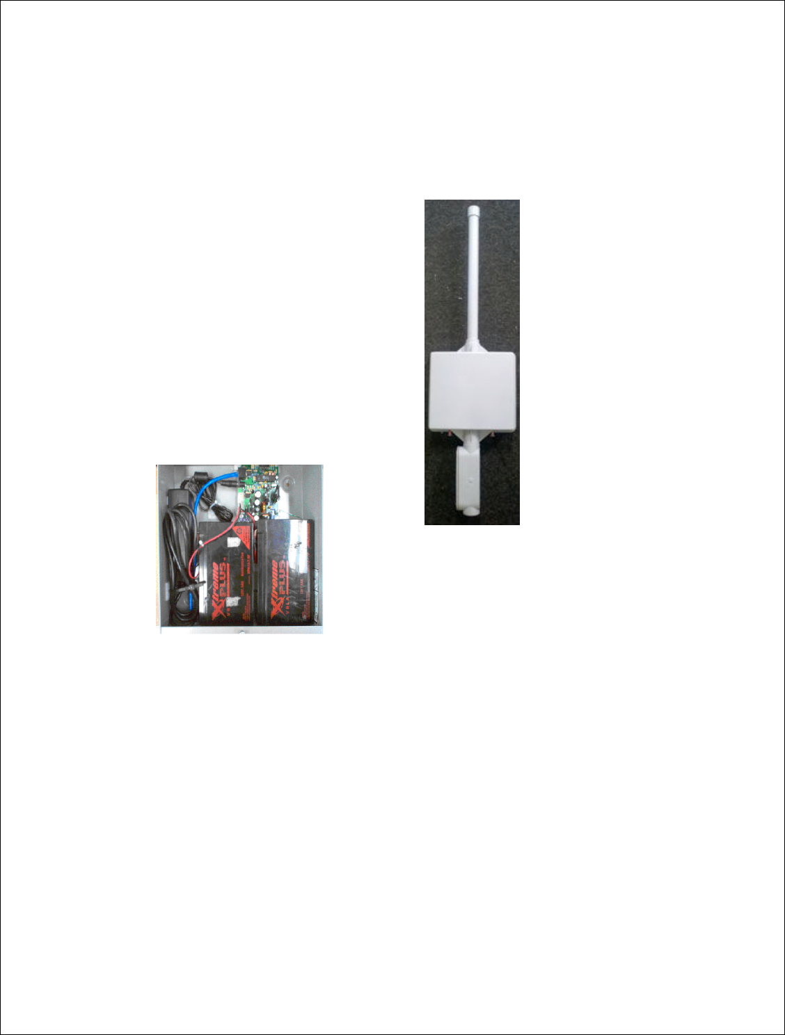
72 | P a g e
DigitalPath, Inc. 275 Airpark Boulevard, Suite 500, Chico, CA 95973 | 800-676-PATH |www.digitalpath.net
CONFIDENTIAL © 2000-2012 DigitalPath, Inc. All rights reserved
Version 5 Power User’s Manual
The
Version 5 Power System
is composed of 3 parts.
a. The Gen5 repeater
b. The power box (CHMONv5.10)
c. The network monitoring system (NMS)
These 3 elements create a
SMART
Un-Interruptible Power System (UPS). In
addition to normal functions such as battery charging and automatic battery
back-up it utilizes hardware and software to achieve remote status indication,
remote command initiation, and Heart-Beat monitoring. Commands can be
sent and status can be read by using the
Network Monitoring System NMS.
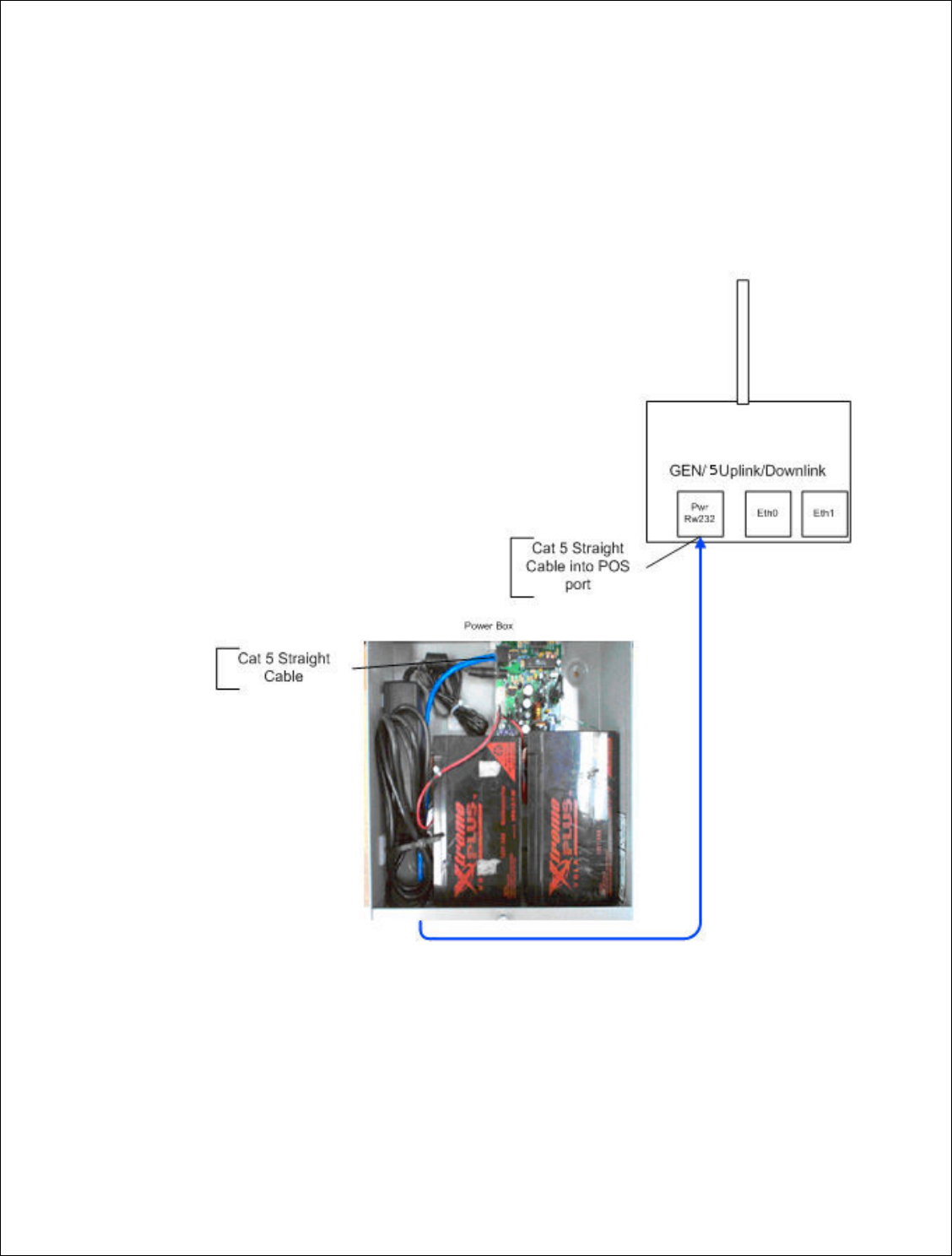
73 | P a g e
DigitalPath, Inc. 275 Airpark Boulevar
CONFIDENTIAL
© 2000
System Diagram
Power system insta
This will be performe
to have a battery bac
diagram of a one rep
levard, Suite 500, C
hico, CA 95973 | 800-676-
PATH |ww
2000
-2012
DigitalPath, Inc. All rights reserved
installation for a gen
5 repeater
rmed multiple times at a tower location. Digitalp
backup system on every gen
5 repeater.
Listed
repeater site.
|www.digitalpath.net
ved
gitalpath prefers
isted below is a
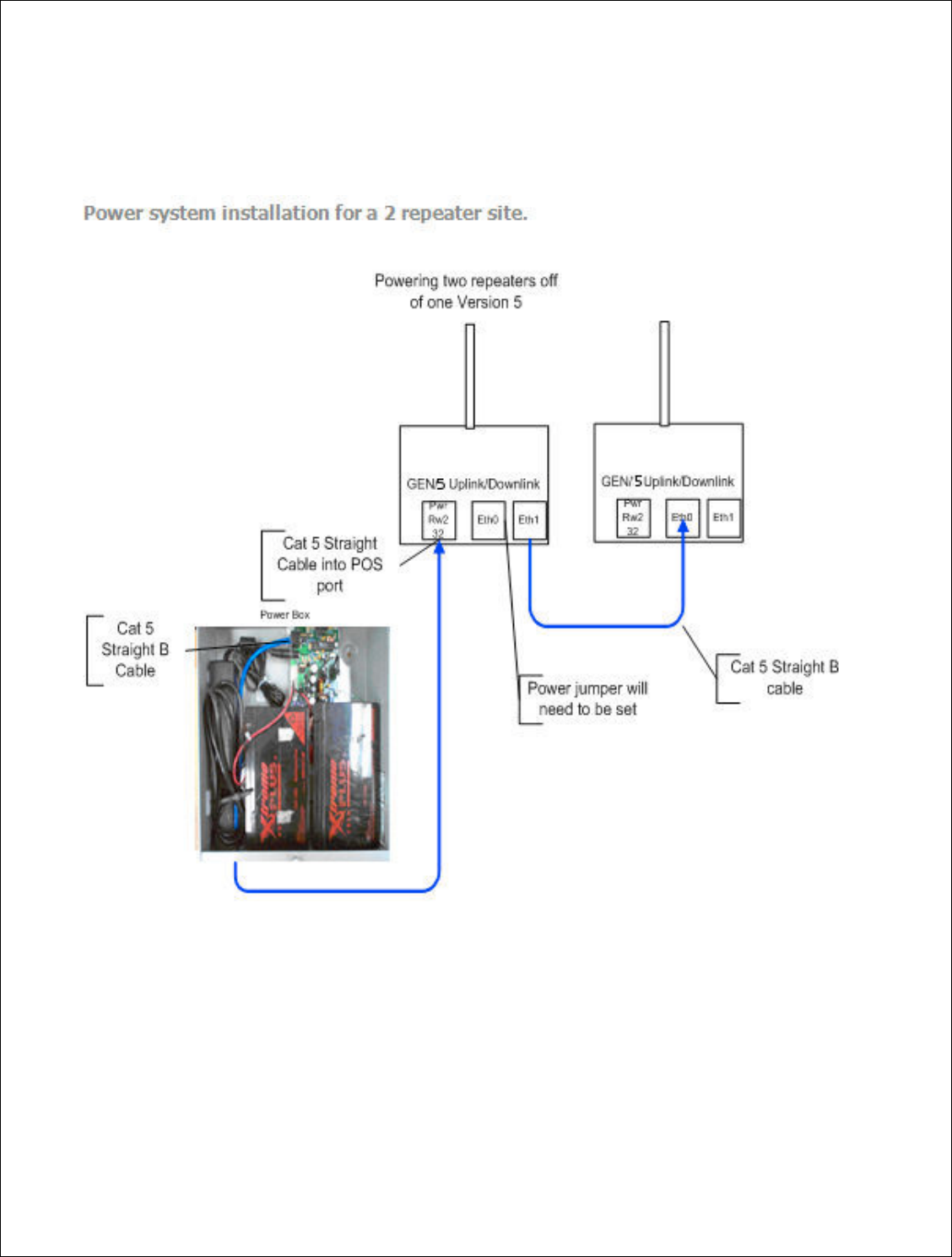
74 | P a g e
DigitalPath, Inc. 275 Airpark Boulevar
CONFIDENTIAL
© 2000
Power system installa
levard, Suite 500, C
hico, CA 95973 | 800-676-
PATH |ww
2000
-2012
DigitalPath, Inc. All rights reserved
tallation for a 2 repeater site.
|www.digitalpath.net
ved
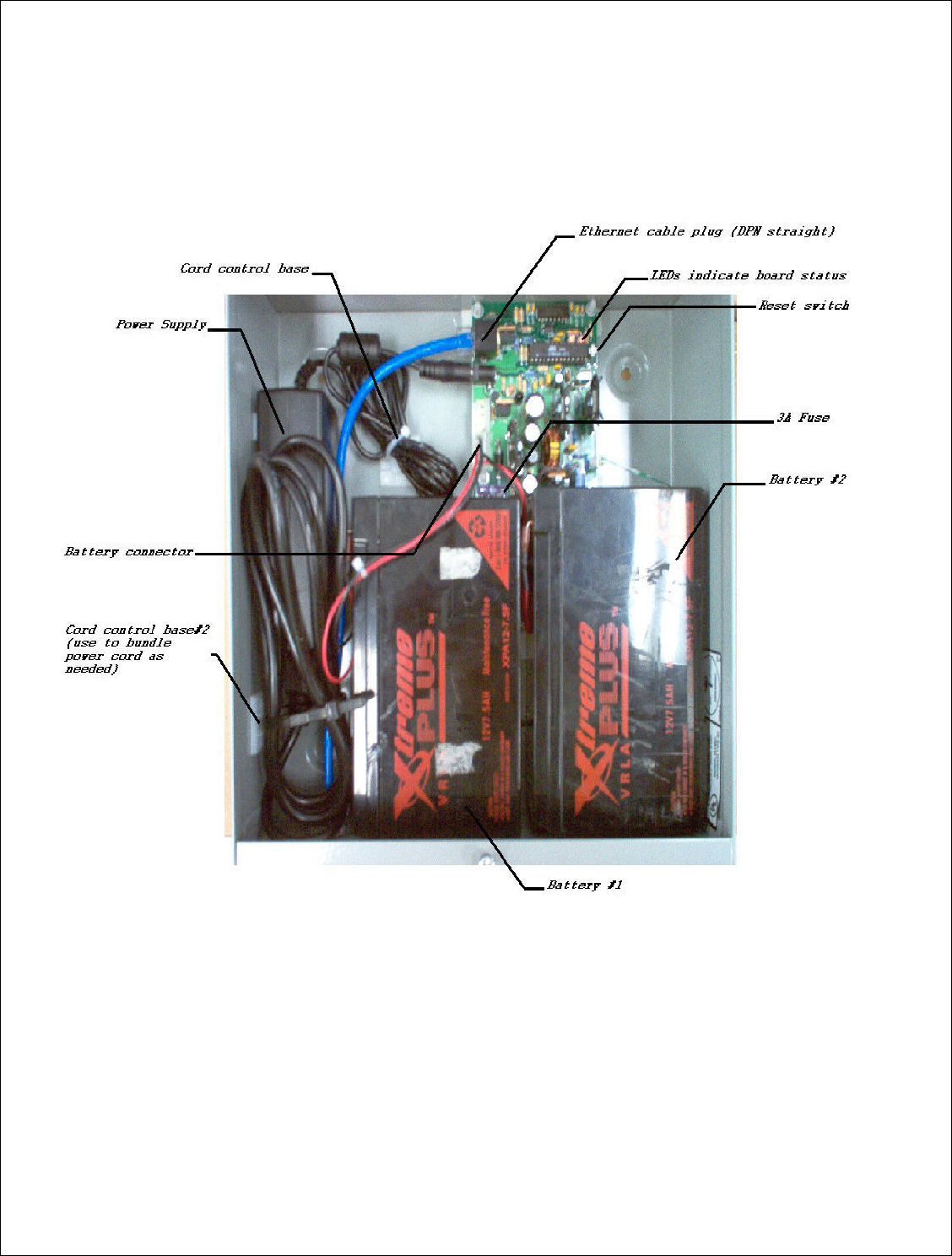
75 | P a g e
DigitalPath, Inc. 275 Airpark Boulevard, Suite 500, Chico, CA 95973 | 800-676-PATH |www.digitalpath.net
CONFIDENTIAL © 2000-2012 DigitalPath, Inc. All rights reserved
Power Box Connections Power System is connected as shown. Refer to
next section (Operation) for power up sequence and status checking.
Figure 1: version 5 Power Box layout
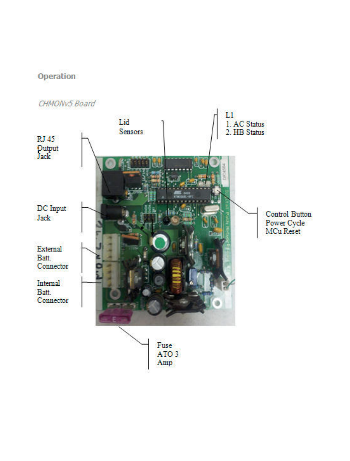
76 | P a g e
DigitalPath, Inc. 275 Airpark Boulevar
CONFIDENTIAL
© 2000
CHMONv5 Board
levard, Suite 500, C
hico, CA 95973 | 800-676-
PATH |ww
2000
-2012
DigitalPath, Inc. All rights reserved
|www.digitalpath.net
ved

77 | P a g e
DigitalPath, Inc. 275 Airpark Boulevard, Suite 500, Chico, CA 95973 | 800-676-PATH |www.digitalpath.net
CONFIDENTIAL © 2000-2012 DigitalPath, Inc. All rights reserved
Operation
Powering Up a Version 5
1. Un-plug RJ45 and batteries form the CHMONv5 board
2. Plug-in and connect AC/DC power supply
3. Plug-in and connect Batteries
4. Reset the MCu
5. Verify that Both LEDs are solid green within 5 seconds
6. Plug-in the RJ45 connector
7. Verify serial data is being received (see figure 2c.1)
*This is recommended for power cycling a repeater, also known as a hard
reset.
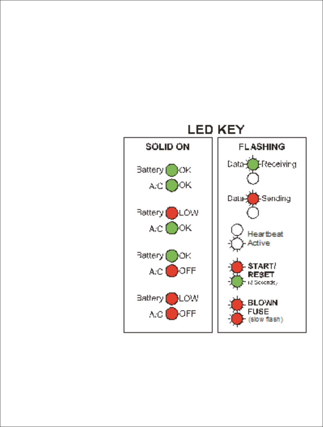
78 | P a g e
DigitalPath, Inc. 275 Airpark Boulevar
CONFIDENTIAL
© 2000
LED Indicators
There are 2 LEDs loca
red or green and they
CHMONv5.
NOTE: When the
Lid is on LEDs will
go off to save
power. If the LEDs
do not come on
make there are no
cords or
obstructions in
front of the IR
sensor
levard, Suite 500, C
hico, CA 95973 | 800-676-
PATH |ww
2000
-2012
DigitalPath, Inc. All rights reserved
s located left of center of t
he board
. Each LED c
they are used to indicate the current status and
|www.digitalpath.net
ved
ED can be either
s and mode of

79 | P a g e
DigitalPath, Inc. 275 Airpark Boulevard, Suite 500, Chico, CA 95973 | 800-676-PATH |www.digitalpath.net
CONFIDENTIAL © 2000-2012 DigitalPath, Inc. All rights reserved
Button Operation
Power Cycle the repeater
Give the button a short push until both LEDs turn red. Power to the
repeater(s) will go off for 5 seconds then back on. The LEDs will slowly
alternate red / red while the power is off.
2c.2. Reset the MCu on CHMONv5
Hold the button down for over 2 seconds until you see the flashing Start-
Up/Reset sequence.
Lid Sensor
CHMONv5 is equipped with an Infrared (IR) lid sensor. The sensor works by
sending and receiving pulses of IR energy every second. It is extremely
important the area immediately above the sensors is kept free of cords or
other obstructions. The lid must also have the reflective tape properly applied
or the sensor will malfunction.
When the Lid is on the LEDs go out to save power. When the lid is removed it
may take up to 2 seconds or (1 minute on older boards) before the LEDs turn
on.
Fuse Replacement
CHMONv5 can sense when it has a blown fuse or a problem with the battery
circuit. If a blown fuse or improperly connected battery is detected CHMONv5
will not check for a fuse again. The MCu must be reset after the fuse is
replaced
CHMONv5 Fuse: ATO 32V 3Amp (Purple)
NOTE:

80 | P a g e
DigitalPath, Inc. 275 Airpark Boulevard, Suite 500, Chico, CA 95973 | 800-676-PATH |www.digitalpath.net
CONFIDENTIAL © 2000-2012 DigitalPath, Inc. All rights reserved
Using a Fuse other than the one specified may result in permanent damage
to CHMONv5
1. Locate the Fuse in Figure 2a.1
2. Pull the Fuse out by rocking it up and down
3. Insert another fuse with the same ratings
4. Reset the MCu (see 2b.2)
5. Verify the LEDs indicate a good fuse

81 | P a g e
DigitalPath, Inc. 275 Airpark Boulevard, Suite 500, Chico, CA 95973 | 800-676-PATH |www.digitalpath.net
CONFIDENTIAL © 2000-2012 DigitalPath, Inc. All rights reserved
Heart-Beat Monitoring
Introduction:
CHMONv5 has the ability to monitor if the repeater that is connected via POS
(Power Over Serial) is operating in a stable state. If the repeater software
locks up CHMONv5 will detect it and initiate a power cycle after 3 minutes. If
the repeater is not able to boot up properly and begin Heart-Beat Monitoring
CHMONv5 will leave the power on and un-interrupted. This is useful for
connecting equipment other than DPN Gen5 repeaters
The Heat-Beat (HB) function utilizes the following items:
Serial RS323 POS (Power Over Serial) link
Service Daemon (PmonD) on the Gen5 repeater
Logic Firmware on the CHMONv5 board
PmonD sends a Heart Beat (HB) signal every 30 seconds. When CHMONv5
receives a HB signal it begins a countdown of 3 minutes. If another signal is
not sent within 3 minutes or 5 HBs CHMONv5 will cycle the power to the
repeaters. CHMONv5 will never enter into monitoring mode if a HB signal is
never sent. CHMONv5 will also only cycle the power ounce if the repeater
fails to come back online.
NOTE:
If CHMONv5 is in Monitoring Mode and it is logged into or processes are killed
that contribute to the Heart-Beat. You will be at risk of CHMONv5 initiating a
power cycle 3 minutes from the time the system was interrupted.

82 | P a g e
DigitalPath, Inc. 275 Airpark Boulevard, Suite 500, Chico, CA 95973 | 800-676-PATH |www.digitalpath.net
CONFIDENTIAL © 2000-2012 DigitalPath, Inc. All rights reserved
ATTACHMENTS

10/14/2010
443999 D01 Approval of DFS UNII Devices v01
1
Federal Communications Commission
Office of Engineering and Technology
Laboratory Division
Interim Plans to Approve UNII Devices Operating in the 5470 - 5725 MHz Band with Radar
Detection and DFS Capabilities
The FCC, NTIA, FAA and industry are working to resolve interference to Terminal Doppler Weather
Radar (TDWR) systems used near airports that has occurred from some outdoor wireless systems
operating in the 5470 MHz – 5725 MHz band. These wireless devices are subject to Section 15.407 of
our rules and when operating as a master device they are required to implement radar detection and DFS
functions. We are continuing our work to develop long-term equipment authorization test procedures
that will ensure that the devices comply with our rules that include protecting the TDWR operations. In
the interim, the Commission will now allow certification of wireless master devices with radar detection
function and with DFS capability, if they meet the following conditions:
xDevices will not transmit on channels which overlap the 5600 – 5650 MHz band.1
xDevices intended for outdoor use will be further restricted, as follows:
oDevices must be professionally installed when operating in the 5470 – 5725 MHz band,2
oGrantees must provide owners, operators and all such installers with specific instructions
in their user’s manual on requirements to avoid interference to TDWRs and information
that meets the following instructions:
Any installation of either a master or a client device within 35 km of a TDWR
location shall be separated by at least 30 MHz (center-to-center) from the TDWR
operating frequency (as shown in the attached table)3, 4, 5, and
1 The devices subject to the requirements in this KDB can select the initial channel for operation to avoid TDWRs and apply
the Uniform Channel Spreading requirements (see FCC 06-96 in ET Docket 03-122 released June 30, 2006) on the remaining
available frequency band of operation. All the other test procedures including the test radar patterns remain the same at the
present time. A revision to the measurement procedure with modification to the Uniform Channel Spreading requirement
and other changes will be released in the future. The Commission will also address the issue of any field upgrade option at
that time.
2 The grantee must identify the specific expertise and the training required by the installers for installing these types of
devices.
3 In some instances it is possible that a device may be within 35 km of multiple TDWRs. In this case the device must ensure
that it avoids operation within 30 MHz for each of the TDWRs. This requirement applies even if the master is outside the 35
km radius but communicates with outdoor clients which may be within the 35 km radius of the TDWRs.
4 The requirement for ensuring 30 MHz frequency separation is based on the best information available to date. If
interference is not eliminated, a distance limitation based on line-of-sight from TDWR will need to be used. In addition,
devices with bandwidths greater than 20 MHz may require greater frequency separation.

10/14/2010
443999 D01 Approval of DFS UNII Devices v01
2
Procedures for the installers and the operators on how to register the devices in
the industry-sponsored database with the appropriate information regarding the
location and operation of the device and installer information is included.6
xDevices must meet all of the other requirements specified in Section 15.407, and it is prohibited
to include configuration controls (e.g. country code settings or other options to modify DFS
functions) to change the frequency of operations to any frequency other than those specified on
the grant of certification for US operation.7
xAll applications for equipment authorization must clearly show compliance with all of the
technical requirements under worst case parameters, under user or operator control, based on
frame rates, listen/talk ratios and user data transfer conditions.
All the devices subject to the DFS requirements must be submitted to the Commission’s Laboratory
Division for pre-grant testing and equipment authorization.8 The applicant must ensure that all
equipment authorization applications subject to this interim procedure include appropriate attestations
that the device has no option to change the DFS parameters and that transmissions are disabled at least
in the 5600 – 5650 MHz band. The application must include the user’s manual with the appropriate
installation and operations requirements for the installers and operators.
We are continuing to evaluate additional measures that may need to be taken to further ensure against
interference caused by 5 GHz outdoor wireless systems located near airports. While manufacturers have
an obligation to ensure that their equipment complies with FCC rules, and must take steps to ensure their
devices are unlikely to cause harmful interference, Section 15.5 of the Commission’s rules also places
an obligation on users of devices to avoid causing interference and to correct any interference that may
occur. We encourage the manufacturers to include information for the users, including the operators and
installers, to ensure that they understand that it is incumbent on them to cooperate with manufacturers to
implement any changes necessary to facilitate compliance.9
5 Devices may be optionally designed not to transmit on channels which overlap 5570 – 5680 MHz instead of requiring
installers to perform site-by-site adjustments. In that case it is still required that the devices should be installed professionally
and the procedures for registering the device in the industry database should be included in the Users Manual.
6 A voluntary WISPA sponsored database has been developed that allows operators and installers to register the location
information of the UNII devices operating outdoors in the 5470 – 5725 MHz band within 35 km of any TDWR location (see
http://www.spectrumbridge.com/udia/home.aspx). This database may be used by government agencies in order to expedite
resolution of any interference to TDWRs.
7 For example, device software must not have any country code options or software configuration settings which allow an end
user to modify the DFS operation or impact the performance of DFS. See KDB 594280.
8 The TCBs are not permitted to approve transmitters with radar detection capabilities. See KDB 628591.
9 The manufacturers may consider taking steps providing clear instructions to operators and installers of devices as to the
need to comply with rules for use of the band, guidance on registration of devices and any other processes that are designed
to avoid interference. They may use methods that include, but are not limited to, instructions in manuals, notification on
product web pages and service bulletins issued for products in the field.

10/14/2010
443999 D01 Approval of DFS UNII Devices v01
3
TDWR Location Information*
STATE CITY LONGITUDE LATITUDE FREQUENCY
TERRAIN
ELEVATION
(MSL) [ft]
ANTENNA
HEIGHT
ABOVE
TERRAIN [ft]
AZ PHOENIX W 112 09 46 N 33 25 14 5610 MHz 1024 64
CO DENVER W 104 31 35 N 39 43 39 5615 MHz 5643 64
FL FT LAUDERDALE W 080 20 39 N 26 08 36 5645 MHz 7 113
FL MIAMI W 080 29 28 N 25 45 27 5605 MHz 10 113
FL ORLANDO W 081 19 33 N 28 20 37 5640 MHz 72 97
FL TAMPA W 082 31 04 N 27 51 35 5620 MHz 14 80
FL WEST PALM BEACH W 080 16 23 N 26 41 17 5615 MHz 20 113
GA ATLANTA W 084 15 44 N 33 38 48 5615 MHz 962 113
IL MCCOOK W 087 51 31 N 41 47 50 5615 MHz 646 97
IL CRESTWOOD W 087 43 47 N 41 39 05 5645 MHz 663 113
IN INDIANAPOLIS W 086 26 08 N 39 38 14 5605 MHz 751 97
KS WICHITA W 097 26 13 N 37 30 26 5603 MHz 1270 80
KY COVINGTON CINCINNATI W 084 34 48 N 38 53 53 5610 MHz 942 97
KY LOUISVILLE W 085 36 38 N 38 02 45 5646 MHz 617 113
LA NEW ORLEANS W 090 24 11 N 30 01 18 5645 MHz 2 97
MA BOSTON W 070 56 01 N 42 09 30 5610 MHz 151 113
MD BRANDYWINE W 076 50 42 N 38 41 43 5635 MHz 233 113
MD BENFIELD W 076 37 48 N 39 05 23 5645 MHz 184 113
MD CLINTON W 076 57 43 N 38 45 32 5615 MHz 249 97
MI DETROIT W 083 30 54 N 42 06 40 5615 MHz 656 113
MN MINNEAPOLIS W 092 55 58 N 44 52 17 5610 MHz 1040 80
MO KANSAS CITY W 094 44 31 N 39 29 55 5605 MHz 1040 64
MO SAINT LOUIS W 090 29 21 N 38 48 20 5610 MHz 551 97
MS DESOTO COUNTY W 089 59 33 N 34 53 45 5610 MHz 371 113
NC CHARLOTTE W 080 53 06 N 35 20 14 5608 MHz 757 113
NC RALEIGH DURHAM W 078 41 50 N 36 00 07 5647 MHz 400 113
NJ WOODBRIDGE W 074 16 13 N 40 35 37 5620 MHz 19 113
NJ PENNSAUKEN W 075 04 12 N 39 56 57 5610 MHz 39 113
NV LAS VEGAS W 115 00 26 N 36 08 37 5645 MHz 1995 64
NY FLOYD BENNETT FIELD W 073 52 49 N 40 35 20 5647 MHz 8 97
OH DAYTON W 084 07 23 N 40 01 19 5640 MHz 922 97
OH CLEVELAND W 082 00 28 N 41 17 23 5645 MHz 817 113
OH COLUMBUS W 082 42 55 N 40 00 20 5605 MHz 1037 113
OK AERO. CTR TDWR #1 W 097 37 31 N 35 24 19 5610 MHz 1285 80
OK AERO. CTR TDWR #2 W 097 37 43 N 35 23 34 5620 MHz 1293 97
OK TULSA W 095 49 34 N 36 04 14 5605 MHz 712 113
OK OKLAHOMA CITY W 097 30 36 N 35 16 34 5603 MHz 1195 64
PA HANOVER W 080 29 10 N 40 30 05 5615 MHz 1266 113
PR SAN JUAN W 066 10 46 N 18 28 26 5610 MHz 59 113
TN NASHVILLE W 086 39 42 N 35 58 47 5605 MHz 722 97
TX HOUSTON INTERCONTL W 095 34 01 N 30 03 54 5605 MHz 154 97

10/14/2010
443999 D01 Approval of DFS UNII Devices v01
4
TX PEARLAND W 095 14 30 N 29 30 59 5645 MHz 36 80
TX DALLAS LOVE FIELD W 096 58 06 N 32 55 33 5608 MHz 541 80
TX LEWISVILLE DFW W 096 55 05 N 33 03 53 5640 MHz 554 31
UT SALT LAKE CITY W 111 55 47 N 40 58 02 5610 MHz 4219 80
VA LEESBURG W 077 31 46 N 39 05 02 5605 MHz 361 113
WI MILWAUKEE W 088 02 47 N 42 49 10 5603 MHz 820 113
* Latitude and Longitude are specified in NAD 83
xLast updated July 30, 2010
xRev. Note (July 30, 2010) – Adjusted coordinates and Elevation Information for Charlotte, NC