007 1387 050
User Manual: 007-1387-050
Open the PDF directly: View PDF ![]() .
.
Page Count: 450 [warning: Documents this large are best viewed by clicking the View PDF Link!]

ImageVision Library™
Programming Guide
Document Number 007-1387-050

ImageVision Library™ Programming Guide
Document Number 007-1387-050
CONTRIBUTORS
Written by George Eckel, Jackie Neider, and Eleanor Bassler
Illustrated by Seth Katz, Nancy Cam, Bill Pickering, and Eleanor Bassler
Edited by Nan Schweiger
Engineering contributions by Chris Walker, Nancy Cam, Venkatesh Narayanan,
Dan Baca, Jon Brandt, Don Hatch, and Casey Leedom
Photography by Jackie Neider, Jim Winget, Nancy Cam, and Judith Quenvold
Cover St. Peter’s Basilica image courtesy of ENEL SpA and InfoByte SpA. Disk
Thrower image courtesy of Xavier Berenguer, Animatica.
© 1993, 1995, 1996, Silicon Graphics, Inc.— All Rights Reserved
The contents of this document may not be copied or duplicated in any form, in whole
or in part, without the prior written permission of Silicon Graphics, Inc.
RESTRICTED RIGHTS LEGEND
Use, duplication, or disclosure of the technical data contained in this document by
the Government is subject to restrictions as set forth in subdivision (c) (1) (ii) of the
Rights in Technical Data and Computer Software clause at DFARS 52.227-7013
and/or in similar or successor clauses in the FAR, or in the DOD or NASA FAR
Supplement. Unpublished rights reserved under the Copyright Laws of the United
States. Contractor/manufacturer is Silicon Graphics, Inc., 2011 N. Shoreline Blvd.,
Mountain View, CA 94043-1389.
Silicon Graphics and IRIS are registered trademarks and IRIS-4D, IRIX, IRIS Graphics
Library, IRIS IM, ImageVision, ImageVision Library, and RealityEngine are
trademarks of Silicon Graphics, Inc. Motif is a trademark of Open Software
Foundation. UNIX is a registered trademark of UNIX System Laboratories. X
Window System is a trademark of the Massachusetts Institute of Technology.
Microsoft is a registered trademark of Microsoft Corporation. Apple and Macintosh
are registered trademarks of Apple Computer, Inc. Kodak and Kodak Photo CD are
trademarks of Eastman Kodak Company.
Red-tailed boa photograph property of Judith Quenvold.

iii
Contents
List of Figures xiii
List of Tables xvii
List of Examples xix
About This Guide xxi
What This Guide Contains xxi
Suggestions for Further Reading xxiii
Adding a User Interface to Your ImageVision Library Program xxv
Style Conventions xxvi
1. Writing an ImageVision Library Program 1
A Sample Program in C++ 2
C++ Version of the Sample Program 3
More about the Sample Program 4
The C Interface 9
Creating and Deleting C++-style Objects 9
Calling Functions 10
Including Header Files 11
A Sample Program in C 11
2. The ImageVision Library Foundation 15
The IL Class Hierarchy 15
Foundation Classes 16
The ilLink Class 17
The ilImage Class 19

iv
Contents
Image Attributes 20
Error Codes 22
Size 22
Data Type 23
Data Ordering 24
Color Model 25
Determining Operator Data Types, Ordering, Working Types, and Definable Fields
26
Color Palette 27
Orientation 28
Fill Value 29
Minimum and Maximum Pixel Values 30
Data Compression 32
The Cache 32
Managing Cache 35
Priority 36
Page Size 38
Multi-threaded Paging Support 39
Accessing Image Data 40
Two-dimensional Functions 40
Three-dimensional Functions 46
Data Access Support Functions 47
Orientation Support 48
Geometric Mapping Support 49
The IL Execution Model 50
On-demand Processing 50
Multi-threading 53
Using Graphics Hardware for Acceleration 55
Working with Image Chains 56
Dynamically Reconfiguring a Chain 57
Propagating Image Attributes 59
Object Properties 61

Contents
v
3. Accessing External Image Data 65
Supported IFL Image File Formats 66
FIT 66
GIF 66
JFIF (JPEG) 67
ilTCL 67
Kodak Photo CD Image Pac 67
Kodak Photo CD Overview Pac 69
PNG 69
PPM/PGM/PBM 69
Raw 69
SGI 70
TIFF 70
YUV 71
Alias 71
SOFTIMAGE 71
Using IL to Access an Image 71
Opening an Existing File 71
Creating an Image File 73
Setting a File’s Compression 75
Querying a File Image 76
Setting and Getting Special Image Properties 77
Importing and Exporting Image Data 78
Images in Memory 78

vi
Contents
4. Operating on an Image 81
Image Processing Operators Provided with IL 84
Color Conversion and Transformation 85
Arithmetic and Logical Transformations 90
Geometric Transformations 98
Spatial Domain Transformations 106
Edge Detection 117
Frequency Domain Transformations 120
Generation of Statistical Data 132
Radiometric Transformations 136
Combining Images 146
Constant-valued Images 152
Using a Null Operator 152
Defining a Region of Interest 153
Creating an ilRoiImg 154
Creating an ilSubImg 156
5. Displaying an Image 159
Overview of the Display Facility 160
Scrolling Windows 164
A Simple Interactive Display Program 165
Sample Program Code 165
Sample Program Comments 167
Creating an ilDisplay 169
Opening an X Window and Creating an ilDisplay Object 169
Adding a View to the ilDisplay Object 170
Deallocating the Display 171
Choosing OpenGL or X Rendering 171

Contents
vii
View and Display Basics 171
Background Color 172
Borders 172
Preventing View Operations 174
Deferring Drawing 174
The Drawing Area 175
Managing the Cache 175
Mode Flags 175
Managing Views 177
Adding Images 177
Stereo Viewing 178
Retrieving Views 179
Retrieving Images 179
Removing Views 180
Replacing Images 180
Reordering the View Stack 180
Finding a View 181
Finding an Edge 181
Operating on a Pixel 182
Locating a Point 183
Applying a Display Operator 184
Drawing Views 184
Relocating Views and Images 188
Resizing Views 193
Updating Views 195
Using setMouse() 196
A More Complicated Interactive Display Program 196
6. Extending ImageVision Library 199
Deriving From ilImage 202
Data Access Functions 203
Color Conversion 207
Managing Image Attributes 207
Deriving From ilCacheImg 212

viii
Contents
Deriving From ilMemCacheImg 213
Implementing an Image Processing Operator 215
Deriving From ilOpImg 217
Handling Image Processing 221
Deriving From ilMonadicImg or ilPolyadicImg 228
Deriving From ilSpatialImg 234
Deriving New Classes From ilWarpImg and ilWarp 237
Deriving From ilFMonadicImg or ilFDyadicImg 238
Deriving From ilFFiltImg 241
Deriving From ilRoi 242
Using an ROI: The ilRoiIter class 243
Deriving New Classes From ilRoi 243
Deriving New Classes From ilRoiIter 243
7. Optimizing Your Application 247
Managing Memory Usage 247
Optimizing Use of Cache 247
Page Size 251
Buffer Space 253
Using Hardware Acceleration 253
Using Accelerated Operators 253
Understanding the OpenGL Imaging Pipeline 255
Composing Operators 256
Pixel Buffers and Multi-Pass Acceleration 258
Texture 259
Texture Allocation 266
Hardware-Specific Acceleration Restrictions 266
General Restrictions 266
InfiniteReality 267
Reality Engine 267
Impact/High Impact 268
Indy/Indigo2 268

Contents
ix
Hardware Hints 268
Using IL-Recognized Hints 269
Creating Your Own Hints 271
8. The Programming Environment 273
Compiling and Linking an IL Program 273
Programs Written in C++ 273
Programs Written in C 275
Reading the Reference Pages 275
Image Tools 277
Online Source Code 277
Environment Variables 278
Caching Configuration Issues 280
Hardware-Acceleration Configuration Issues 280
Hardware Display Configuration Issues 280
Monitoring Control Issues 281
Multi-Threading Configuration Issues 283
A. What is New in Version 3.1 285
keepPrecision() Added to ilOpImg 285
Multiprocessing on Single CPU Machines Enabled 285
Additional Image Formats Supported 285
ELT Performance Enhanced 286
Choosing OpenGL or X Rendering 286
API Change for ilImgStat 286
B. What is New in Version 3.0 287
Overview of Changes in 3.0 287
Understanding the New Features 288
Support for OpenGL and Hardware Acceleration 288
64-bit Address Space Support 289
Understanding New Classes 289

x
Contents
Understanding the Changes to the Existing Features 292
Multi-threading Architecture Changes 292
Asynchronous Operations 292
Changes to the Display Facility 294
Error handling 295
Polynomial Coordinate Structures 296
Run-time Object-Type Query Macros 297
Changes to Existing Classes 298
Backwards Compatibility with IL 2.5 306
Automatic Class Name Conversion 308
New Derivations for Classes 313
C. Introduction to C++ 315
Objects and Classes 315
Overloaded Functions 316
Inheritance 317
Public versus Protected versus Private 318
Passing by Reference 318
Default Values 318
Class Declaration Format 319
Linking with Libraries in Other Languages 319
Referring to Function Names 321
D. Summary of All Classes 323
E. Implementing Your Own Image File Format 337
Deriving and Implementing Your Image File Format Class 337
Opening an Existing File 338
Creating a New Image File 340
Closing a File 342
Parsing the File Name 344
Reading and Writing Formatted Data 345
Functions that Manipulate the Image Index 348
Adding Images to Image Files 349

Contents
xi
Deriving an Image File Format from iflFormat 350
Deriving Subclasses 350
Virtual Function Descriptions 351
Sample Code for Virtual Function Definitions 353
Registering an Image File Format 354
Using the File Format Database 354
F. Auxiliary Classes, Functions, and Definitions 357
Auxiliary Classes 358
iflConfig 359
Using iflLut 360
Useful Functions 362
Computing the Size of Data Types 363
Minimum and Maximum Comparisons 364
Converting to Color-index Mode 364
Convenient Structures 365
Coordinate Data Structures 365
Error Codes 366
ilStatus Error Codes 366
iflStatus Error Codes 368
Enumerated Types and Constants 369
Describing Image Attributes 370
G. Using the Electronic Light Table 375
Understanding How ELT Works 375
DeWarping the Image 377
RotZooming the Image 377
Convolving the Image 377
Collecting Histogram Data 378
Dynamically Adjusting the Image 379
DeWarping the Image Data 379
Enabling and Disabling Operators 380
Setting Operator Values 381

xii
Contents
Understanding Accelerated Performance 381
Look-ahead Algorithms 381
Hardware Acceleration 382
Image Size 382
Choosing a Display in ELT Applications 383
Creating an ELT Application 383
Understanding the ilELTImg API 388
H. Results of Operators 395
Color Conversion 396
Arithmetic and Logical Transformations 397
Geometric Transformations 400
Spatial Domain Transformations 401
Edge Detection 402
Frequency Domain Transformations 404
Radiometric Transformations 405
Combining Images 407
Index 409

xiii
List of Figures
Figure 1-1 An Image before Processing 6
Figure 1-2 The Image after Processing 8
Figure 2-1 The ilLink Class Inheritance 17
Figure 2-2 An IL Chain 18
Figure 2-3 Sizes of Original and Processed Images 23
Figure 2-4 Pixel Data Ordering for an RGB Image 24
Figure 2-5 Determining Color Model Inheritance for Operator Images 26
Figure 2-6 Image orientations 29
Figure 2-7 Cache Containing Portions of Three Images 33
Figure 2-8 Pages and Tiles of Image Data 34
Figure 2-9 Priority Lists in Cache 37
Figure 2-10 Parameters for getSubTile() and setSubTile() 45
Figure 2-11 Image Chain for the Sample Program 51
Figure 2-12 Image Chain Showing Demand-driven Execution Model 52
Figure 2-13 Performance Comparison of Non-threaded, Single-processor, and
Multi-processor Applications 53
Figure 2-14 Operators, Requests for Pages, and Threads 55
Figure 2-15 An Image Chain 57
Figure 4-1 ilOpImg and IL Inheritance Hierarchy 82
Figure 4-2 Color Conversion Operators Inheritance Hierarchy 85
Figure 4-3 Determining the Color Model of Multi-Input Operators 87
Figure 4-4 A Falsely Colored Image 89
Figure 4-5 Arithmetic and Logical Operators Inheritance Hierarchy 91
Figure 4-6 A Positive and Negative Image Pair 93
Figure 4-7 Adding Two Images 96
Figure 4-8 Minimum of Two Images 97
Figure 4-9 Logical AND and OR of Two Images 98

xiv
List of Figures
Figure 4-10 A Warped Image 99
Figure 4-11 Geometric Operator Inheritance Hierarchy 99
Figure 4-12 Warping an Image 104
Figure 4-13 Spatial Domain Operator Inheritance Hierarchy 106
Figure 4-14 The ilPadSrc Edge Mode 108
Figure 4-15 An Original Image 110
Figure 4-16 An Image Blurred with ilBlurImg 111
Figure 4-17 An Image Sharpened with ilSharpenImg 112
Figure 4-18 An Over-sharpened Image 112
Figure 4-19 Median Rank Filtering on an Image 114
Figure 4-20 Edge Detection Operator Inheritance Hierarchy 117
Figure 4-21 Edge Image Produced by ilRobertsImg 118
Figure 4-22 A Compass Filtered Image 120
Figure 4-23 Frequency Domain Operator Inheritance Hierarchy 121
Figure 4-24 Magnitude and Phase Fourier Operators 125
Figure 4-25 Original Image 129
Figure 4-26 Image Processed with ilFGaussFiltImg 129
Figure 4-27 The ilImgStat Inheritance 133
Figure 4-28 Radiometric Operator Inheritance Hierarchy 137
Figure 4-29 Using Scaling 139
Figure 4-30 Breakpoints along a Piecewise Continuous Function 143
Figure 4-31 Using a Lookup Table Editor to Set Breakpoints 146
Figure 4-32 ilBlendImg, ilMergeImg, and ilCombineImg Inheritance Hierarchy 146
Figure 4-33 Blended Images 148
Figure 4-34 Composition Modes for ilBlendImg 150
Figure 4-35 lRoi’s Subclasses 155
Figure 4-36 Source Image and Subimage 156
Figure 4-37 Translated Subimage 157
Figure 5-1 IL Display Classes 160
Figure 5-2 Stacked Images in an X Window 161
Figure 5-3 ilDisplay Object Creates a Display Area 162
Figure 5-4 ilView Objects Map Images to Display Regions 163
Figure 5-5 Display Area After Views Are Drawn 164

List of Figures
xv
Figure 5-6 Aligning an Image to Bottom Left Corner 189
Figure 5-7 Aligning Views 189
Figure 5-8 split() with ilAbsSplit | ilRowSplit | ilColSplit 192
Figure 5-9 split() with ilRelSplit | ilRowSplit | ilColSplit 192
Figure 5-10 Using wipeSize() 195
Figure 6-1 User-Defined Classes in IL 200
Figure 6-2 ilOpImg and Its Subclasses for Deriving 216
Figure 6-3 Using qgetSubTile3D() 223
Figure 6-4 Visualizing a ROI 242
Figure 7-1 Varying Page Dimensions 249
Figure 7-2 OpenGL Image Processing Pipeline 256
Figure 7-3 IL Chain Mapped to the OGLIP Pipeline 257
Figure 7-4 Mapping onto the OGLIP in a Single Transfer 257
Figure 7-5 Running a Subsection of an IL Chain 258
Figure 7-6 Two-Pass Transfer Operations 259
Figure 7-7 Accelerating an IL Chain Using Texture 260
Figure 7-8 Data Path of the IL Chain in Figure 7-7 261
Figure 7-9 Hardware Acceleration Without Using Pixel Buffers 263
Figure 7-10 Hardware Acceleration Using Pixel Buffers 265
Figure C-1 Sample Inheritance Hierarchy 317
Figure G-1 ELT image processing pipeline 376
Figure H-1 ilFalseColorImg 396
Figure H-2 ilGrayImg 396
Figure H-3 Original Image and Flipped Image 397
Figure H-4 ilAddImg and ilAndImg 397
Figure H-5 ilDivImg 397
Figure H-6 ilExpImg and ilInvertImg 398
Figure H-7 ilLogImg and ilMaxImg 398
Figure H-8 ilMinImg and ilMultiplyImg 398
Figure H-9 ilNegImg and ilOrImg 399
Figure H-10 ilPowerImg and ilSqRootImg 399
Figure H-11 ilSquareImg and ilSubtractImg 399
Figure H-12 ilXorImg 400

xvi
List of Figures
Figure H-13 Original and ilRotZoomImg 400
Figure H-14 ilWarpImg 401
Figure H-15 Original, ilBlurImg and ilGBlurImg 401
Figure H-16 ilDilateImg, ilErodeImg, and ilMaxFltImg 401
Figure H-17 ilMedFltImg, ilMinFltImg, and ilSharpenImg 402
Figure H-18 ilCompassImg 402
Figure H-19 ilLaplaceImg (original and filtered image) 402
Figure H-20 ilRobertsImg (original and filtered image) 403
Figure H-21 ilSobelImg (original and filtered image) 403
Figure H-22 ilFGaussFiltImg 404
Figure H-23 ilHistEqImg (filtered image and histogram) 405
Figure H-24 ilHistNormImg (filtered image and histogram) 405
Figure H-25 ilHistScaleImg (filtered image and histogram) 406
Figure H-26 ilLutImg (original, filtered image, and LUT editor) 406
Figure H-27 ilThreshImg 406
Figure H-28 Originals and Original Mask 407
Figure H-29 ilBlendImg 407
Figure H-30 ilCombineImg 408

xvii
List of Tables
Table 1-1 IFL-supported Image Formats 6
Table 2-1 Image Attribute Summary 21
Table 2-2 Data Access Functions 40
Table 2-3 Channel Mapping 43
Table 3-1 Compression Algorithms Supported for ilTIFFImg Files 75
Table 3-2 File Query Functions 76
Table 3-3 Color Models 79
Table 4-1 Single-input Arithmetic Operators and Their Valid Output Data Types
92
Table 4-2 Compass Directions for the ilCompassImg Operator 119
Table 4-3 Output of a Forward Fourier Transform (if nx and ny are even) 123
Table 4-4 Output of a Forward Fourier Transform (if nx and ny are odd) 123
Table 4-5 Sample Parameter Values for ilFGaussFiltImg 128
Table 6-1 Image Attributes Needing Initialization in ilImage Subclass 202
Table 6-2 ilImgParam Constants 209
Table 6-3 Additional Attributes Needing Initialization in ilMemCacheImg
Derived Classes 214
Table 6-4 Classes Derived from ilMonaDicImg and ilPolyadicImg 229
Table 6-5 ilSpatialImg’s Subclasses 234
Table 6-6 The Subclasses of ilFMonadicImg and ilfDyadicImg 238
Table 7-1 ilHwHint Definitions 270
Table 8-1 Environment Variable Definitions 278
Table B-1 New Names for Polynomial Structures 297
Table B-2 Run-time Object Inquiries 297
Table B-3 Class Name Conversions 308
Table B-4 New Class Hierarchies 313
Table D-1 Summary of All Classes 323

xviii
List of Tables
Table E-1 iflFormat’s Virtual Functions 351
Table F-1 Coordinate Data Structures 365
Table F-2 ilStatus Error Codes 366
Table F-3 iflStatus Error Codes 368
Table G-1 Methods in ilELTImg 388

xix
List of Examples
Example 1-1 Sample Program (in C++) Using X Window Management 3
Example 1-2 Sample Program (in C) Using X Window Management 11
Example 3-1 Opening an Image File and Reading Data 72
Example 5-1 A Simple Interactive Display Program 165
Example 5-2 A More Complicated Interactive Display Program 197
Example 6-1 Typical Header for a Class Derived From ilOpImg 217
Example 6-2 Typical Constructor for a Class Derived From ilOpImg 218
Example 6-3 The resetOp() Function of ilMonadicImg 220
Example 6-4 A Request-Processing Implementation for a Class Derived From
ilOpImg 224
Example 6-5 Computing the Pixelwise Sum of Two Images 226
Example 6-6 Implementation of ilArithDoCalc() in ilPowerImg 231
Example 6-7 Implementation of loadLut() in ilPowerImg 232
Example 6-8 A Class Derived From ilHistLutImg to Count Pixels 233
Example 6-9 A Class Derived From ilConvImg to Multiply and Accumulate Data
236
Example 6-10 Constructor and Member Functions of a Class Derived From
ilFMonadicImg to Convert Coordinates 239
Example 6-11 A Class Derived From ilFDyadicImg to Multiply Two Fourier Images
240
Example 7-1 Using the Hint Name to Set a Hint 269
Example 8-1 Makefile for a C++ Program 274
Example 8-2 Makefile for a C Program 275
Example C-1 Class Declaration Format 319
Example E-1 Opening a File 339
Example E-2 Creating a File 341
Example E-3 Closing a File 343
Example E-4 Flushing a Buffer 344

xx
List of Examples
Example E-5 Reading and Writing Data in the FIT Format 347
Example E-6 Defining Virtual Functions for Your Image File Format 353
Example F-1 iflConfig Constructors and Fields 359
Example F-2 iflLut Constructors and Member Functions 361
Example G-1 Coding an ELT Application 384

xxi
About This Guide
The ImageVision Library™ (IL) is an object-oriented, extensible toolkit designed for
developers of image-processing applications. Typical image processing programs access
existing image data, manipulate it, display it, and save the processed results. IL provides
a robust framework within which developers can easily create such programs to run on
all Silicon Graphics® workstations.
IL consists of a library written in the C++ programming language; interfaces for the C
language are also available. The object-oriented nature of C++ provides a simplified
programming model based on abstractions of what images are and how they are
manipulated. This model relieves developers of many tedious programming details and
allows them to conceptually design creative programming solutions. Also, because IL is
written in C++, developers can easily extend it, for example, to incorporate their own
image processing algorithms or to include support for their own image file formats.
Several examples of images produced using IL appear in Chapter 4, “Operating on an
Image.”
What This Guide Contains
This guide presents a task-oriented perspective of IL. The topics in this guide are
arranged to coincide with the order in which you need to refer to them while writing an
image processing program. To illustrate the use of IL, code examples are sprinkled
liberally throughout the guide. Additional sample source code is provided online; see
“Online Source Code” on page 277. Brief descriptions of the chapters in this guide follow:
•Chapter 1, “Writing an ImageVision Library Program,” shows what a typical image
processing application that uses IL looks like. It presents an IL program that
performs the tasks common to many image processing applications. It also
summarizes the differences among the C++, C, and Fortran interfaces to IL.
•Chapter 2, “The ImageVision Library Foundation,” explains the general architecture
and design philosophy of IL. Most of this chapter is devoted to discussion of the
principal image class (ilImage), from which virtually all IL classes derive, and the
class that implements a key part of IL’s execution model (ilCacheImg).

xxii
About This Guide
• Chapter 3, “Accessing External Image Data,” describes how to read and write
image data from and to either a file on disk or memory.
•Chapter 4, “Operating on an Image,” discusses the more than 70 image processing
algorithms provided with IL. It explains how to use them and what effect they have
on image data.
•Chapter 5, “Displaying an Image,” describes how to display and manage a set of
images on the screen in an interactive program. You can allow a user of your
program to move images, perform wipes, roam around an image, and create split
views of multiple images.
•Chapter 6, “Extending ImageVision Library,” explains how to extend the
capabilities of IL to implement your own derived classes. You might extend IL to
include support for your own file format or to incorporate your own image
processing algorithm.
•Chapter 7, “Optimizing Your Application,” provides information on optimizing
your IL programs by reducing memory usage, taking advantage of hardware
acceleration, and making use of IL’s multi-threading facility.
•Chapter 8, “The Programming Environment,” provides information on the
programming environment available on Silicon Graphics workstations. It mentions
special tools that may help you in writing, compiling, and debugging your IL
program.
In addition to these chapters, this guide includes several appendices as handy
summaries of useful information:
•Appendix A, “What is New in Version 3.1,” describes the differences between
versions 3.0 and 3.1 of the ImageVision Library.
•Appendix B, “What is New in Version 3.0,”describes the differences between versions
2.5 and 3.0 of the ImageVision Library.
•Appendix C, “Introduction to C++,” contains a brief introduction to the principles
of C++ programming.
•Appendix D, “Summary of All Classes,” provides a brief summary of all the classes
that make up IL.
•Appendix E, “Implementing Your Own Image File Format,” describes how to add
and implement your own image file format.

About This Guide
xxiii
•Appendix F, “Auxiliary Classes, Functions, and Definitions,” describes IL classes
not fully discussed elsewhere in this guide. It also lists all the error codes and
enumerated types used by IL.
•Appendix G, “Using the Electronic Light Table,” describes the ilELT Img operator
and how you use it along with ilDisplay, ilView, and ilStereoView to create an ELT
application.
•Appendix H, “Results of Operators,” contains illustrations showing the results of
using IL’s operators to process data.
Other documentation on IL is contained in the ImageVision Library Reference Pages. These
reference pages provide concise yet thorough descriptions of each C++ class included in
IL. They are only available online in versions for C++, C, and Fortran programmers. See
“Reading the Reference Pages” on page 275 for more information on the exact content of
the reference pages.
Suggestions for Further Reading
Because IL is written in C++, it is easiest to describe its design philosophy and how to
program with it by talking about the C++ classes that compose IL. While it is not
necessary that you know how to program in C++, you can gain more from this guide if
you understand the concepts of object-oriented programming. Where possible, however,
this guide avoids focusing on topics directly related to the C++ implementation of IL. In
addition, a brief introduction to C++ is included in Appendix C. Programming examples
in Chapter 1, “Writing an ImageVision Library Program,” are given in C++, C, and
Fortran. Some books on C++ you might find helpful include:
•Ellis, Margaret, and Bjarne Stroustrup. The Annotated C++ Reference Manual. AT&T
Bell Laboratories, 1990. The official C++ language reference manual.
•The C++ Programmer’s Guide. A short manual that provides information about
implementing C++ programs on Silicon Graphics workstations.
•Lippman, Stanley. C++ Primer. AT&T Bell Laboratories, 1991. An introductory-level,
tutorial-style presentation of C++.

xxiv
About This Guide
This guide assumes that you are familiar with the principles of image processing. A
good, general discussion of image processing can be found in any of several textbooks,
such as:
•Jain, Anil K. Fundamentals of Digital Image Processing. Prentice-Hall, Inc., 1989. A
thorough presentation of the major concepts of image processing, written for
graduate students.
•Pratt, William K. Digital Image Processing. John Wiley & Sons, 1991.
•Gonzalez, Rafael C., and Richard E. Woods. Digital Image Processing.
Addison-Wesley, 1992.
To learn more about the RealityEngine™ architecture, read:
•Akeley, Kurt, and Tom Jermoluk. RealityEngine Graphics™. In Proceedings of
SIGGRAPH ‘93 (August 1993), pp. 109-116.
Most sample programs in this guide include calls to the IRIS Graphics Library™ (GL), and
IL itself uses the GL to perform rendering in the frame buffer. These calls are not
explained in much detail since the GL is documented separately in these Silicon Graphics
books:
• Graphics Library Programming Guide
• Graphics Library Reference Pages
• Graphics Library Programming Tools and Techniques
IL provides support for manipulating files stored in the format defined by Tag Image File
Format (TIFF), Revision 6.0, distributed by Aldus Corp. You might want to obtain the
official specification of this format directly from Aldus (411 First Avenue South; Suite 200;
Seattle, WA 98104; (206) 628-6593).
• TIFF 6.0 Specification
IL provides support for multi-threading on single- and multi-processor machines. If you
want to know more about writing multi-threaded applications, refer to this document:
• Parallel Programming on Silicon Graphics Computer Systems

About This Guide
xxv
IL uses dynamic linking. To learn more about using dynamic linking with your
applications, read:
•the dlopen, dlsym, and dlerror reference pages
• IRIX™ Programming Guide
Adding a User Interface to Your ImageVision Library Program
IL does not impose any particular user interface (UI), so you can use any UI toolkit—such
as IRIS IM™, Silicon Graphic’s port of the industry-standard OSF Motif™—to allow the
user to control your program. To support such interactive control, IL provides many
functions for altering parameters dynamically. IL also keeps track of when parameters
have changed so that image data can be updated automatically. These user-interface
manuals are available from Silicon Graphics:
• OSF/Motif Programmer’s Guide
• OSF/Motif Programmer’s Reference
• OSF/Motif Style Guide
• IRIS IM Programming Notes
Silicon Graphics recommends that you write mixed-model programs rather than pure
GL programs. A mixed-model program is essentially an X program that uses the GL to
handle graphics; the GL is completely removed from all areas governed by the X server.
If you are creating a mixed-model X Window System™ and IL program, you might also
want to refer to these volumes in the O’Reilly X Window System Series, published by
O’Reilly & Associates, Inc., Sebastopol, California:
•Volume One: XLIB Programming Manual, by Adrian Nye
•Volume Four: X Toolkit Intrinsics Programming Manual, by Adrian Nye and Tim
O’Reilly
Volumes One and Four are available from Silicon Graphics as part of the IRIS®
Development Option (IDO).

xxvi
About This Guide
Style Conventions
These style conventions are used in this guide:
•Bold—Functions, data members, and data types
•Italics—Variables, filenames, spatial dimensions, and command
•Regular—Class names and enumerated types
Code examples are set off from the text in a fixed-space font.

1
Chapter 1
1. Writing an ImageVision Library Program
To write an image processing program, you use the C++ classes in the ImageVision
Library (IL). This chapter shows several, typical image processing applications.
This chapter contains the following major sections:
•“A Sample Program in C++” on page 2 presents a sample program written in C++
that uses the IL. The section shows the program that uses X window management.
•“The C Interface” on page 9 explains the differences between the C++ and C
interfaces to the IL.
•“A Sample Program in C” on page 11 presents the sample program written in C.

2
Chapter 1: Writing an ImageVision Library Program
A Sample Program in C++
The sample C++ program presented in this section reads image data from a file,
processes it, displays it, and saves the processed data in a new file. Each task the program
performs is described in more detail in subsequent chapters. This chapter gives you a
brief introduction to the capabilities of the IL and provides you with a code example that
can serve as a template for programs you write.
Image processing applications typically perform at least some of the following tasks:
Read image data
Read formatted image data from a file on disk, for example, and
decompress it if necessary.
Process the data
Manipulate the data, for example, to enhance the original image or to
produce a statistical analysis of the data.
Display the image on the screen
Allow a user to interactively view selected portions of
simultaneously-displayed images.
Save the processed data in a file
Format and possibly compress the data.
The C++ program presented in Example 1-1 demonstrates how the IL accomplishes these
tasks. (A version of this program in the C language appears later in this chapter.) In
Example 1-1, the user invokes the program from the command line and specifies a file of
image data to be processed. The program then performs the following tasks:
1. Opens the input file of image data.
2. Constructs a sharpening operator that uses the file of image data as input.
3. Constructs a rotate operator that uses the output of the sharpening operator as
input.
4. Displays the sharpened and rotated image data on the screen.
5. Continues to display the processed image until the user quits by pressing the <Ctrl>
<q> keys or by using the window menu.
6. Copies the sharpened and rotated image to a file on disk.

A Sample Program in C++
3
The code for this program is available online so that you can easily compile and run it.
Look in:
/usr/share/src/il/guide/sampleProg.c++
Other sample code is also available online; see “Online Source Code” on page 277.
C++ Version of the Sample Program
The code in Example 1-1 shows the C++ version of the sample program.
Example 1-1 Sample Program (in C++) Using X Window Management
#include <stdlib.h>
#include <stdio.h>
#include <X11/Xlib.h>
#include <X11/keysym.h>
#include <il/ilFileImg.h>
#include <il/ilSharpenImg.h>
#include <il/ilRotZoomImg.h>
#include <il/ilViewer.h>
void
main(int argc, char **argv)
{
// Step 1: Open the file of image data.
if (argc < 2) {
printf("Usage: %s <filename>\n", argv[0]);
exit(0);
}
ilFileImg inImg(argv[1]);
// Step 2: Create IL objects for sharpening and rotating
ilSharpenImg sharperImg(&inImg, 0.5);
ilRotZoomImg rotatedImg(&sharperImg, 90.0);
// Step 3: Set up and open a window for display.

4
Chapter 1: Writing an ImageVision Library Program
iflSize size;
rotatedImg.getDimensions(size);
Display* dpy = XOpenDisplay(NULL);
ilViewer viewer(dpy, size.x, size.y);
// Step 4: Display the processed data.
viewer.addView(&rotatedImg, ilLast, ilCenter);
// Step 5: Display until the user quits.
viewer.eventLoop();
XCloseDisplay(dpy);
// Step 6: Write the processed data to a file.
iflFileConfig fc(&size);
ilFileImg tmpFile("outFile.tif", &inImg, &fc);
tmpFile.copy(&rotatedImg);
tmpFile.flush();
}
More about the Sample Program
The sample program uses the IL in a recommended way, but many good programming
habits were not followed in the interest of keeping the program short. More specifically,
this program does not do any of the following things:
•check return arguments and write error messages as appropriate
•strip arguments off the command line in an elegant way and check them for
appropriate values (or provide a graphical user interface)
•provide feedback to the user, for example, to indicate that a file of processed image
data has been created
The remainder of this section walks through Example 1-1, explaining how it uses the IL.
This discussion is intended to give you a taste of the kinds of things the IL can do and
what you, as a programmer, need to do to accomplish them. Each of the following topics
is discussed extensively elsewhere in this book.

A Sample Program in C++
5
Header Files
The first few lines of code include the necessary header files from the IL. These header
files also include other IL header files, as well as header files from the Graphics Library
and the standard C library. If you use this program as a template and modify it to suit
your needs, be sure you include the header files necessary for your program. Since the IL
provides many more capabilities than you need for any particular program, you do not
need to include all of its header files. To minimize compile time and the size of your
executable, you should include only those header files actually required by your
program.
In this example,
•the header X11/Xlib.h is included to configure an X window for OpenGL rendering
•the header X11/keysym.h is included to handle user input
•the header il/ilFileImg.h is included to implement the ilFileImg class
•the header il/ilSharpenImg.h is included to implement the ilSharpenImg class
•the header il/ilRotZoomImg.h is included to implement the ilRotZoomImg class.
•the header il/ilViewer.h is included to manage views in an X window.
In general, when writing an IL program in C++, you will need to include an IL header
file for each IL class you use. More information about programming and compiling IL
programs is included in “Compiling and Linking an IL Program” on page 273.
Step 1: Open the File of Image Data
In step 1 of Example 1-1, an image data file specified by the user is opened by invoking
the ilFileImg constructor. This function takes one argument: the pathname of the file. In
this example, the filename is taken as an argument from the command line and the file is
opened for reading. Figure 1-1 shows an example image file.
6
Chapter 1: Writing an ImageVision Library Program
Figure 1-1 An Image before Processing
Before any image data can be read, the ilFileImg constructor determines the format of the
image file by returning a pointer to one of the supported ilFileImg types. IL recognizes
the image file formats at runtime by searching for dynamic shared objects (DSOs) that
contain the code for specific file formats. Table 1-1 shows all of the IFL -supported image
file formats and their customary suffixes.
Table 1-1 IFL-supported Image Formats
File Format Customary Suffix
SGI .rgb, .sgi, .rgba, .bw, .screen
TIFF .tif, .tiff
JFIF .jpg, .jpeg, .jfif
FIT .fit
PCD .pcd
PCDO pcdo
GIF .gif
PPM .ppm, .pgm, .pbm, .pnm
PNG .png
Raw .raw

A Sample Program in C++
7
IFL is a lower-level library upon which IL is built.
You can also create your own image file formats. For more information about defining
image file formats, see Appendix E, “Implementing Your Own Image File Format.”.
Step 2: Create IL Objects for Sharpening and Rotating
Now that the source of the image data is ready, the IL objects used for processing the data
are created in step 2. For this sample program, data is first sharpened and then rotated
by using the ilSharpenImg and ilRotZoomImg classes. These two classes demonstrate
two of the many image manipulation functions included in the IL.
As shown in Example 1-1, the parameter 0.5 is passed in with a pointer to the input
image data file to create the sharpening object. This parameter, which is a
single-precision floating point number, can range in value from 0 to 1; it defines how
much the data is sharpened. The specific algorithm that ilSharpenImg uses to sharpen
image data is described in detail in its class reference page (read “Reading the Reference
Pages” on page 275 for an explanation of the difference between normal reference pages
and class reference pages). If this were an interactive program, you could allow the user
to change the sharpness factor dynamically, perhaps with a slider widget.
You can use the ilRotZoomImg class to rotate and/or zoom (magnify or minify) an
image. In Example 1-1, the sharpened image data is rotated 90 degrees, in a
counterclockwise direction, as specified by the parameter passed to ilRotZoomImg. The
ilRotZoomImg class is discussed in detail in its reference page.
The program uses the size of the rotated image to set the size of the X window opened to
display the image.
You can invoke any number of operators on a set of data. See Chapter 4, “Operating on
an Image,” for more information about how the IL allows you to operate on image data.
You can also easily add your own algorithms; “Implementing an Image Processing
Operator” on page 215, tells you how to extend the IL to include a new image processing
operator.
As an IL program executes, image data is processed only on demand, for example, when
it’s needed for displaying or writing to a file. This execution model eliminates
unnecessary processing and minimizes transfers of data in and out of memory. In
Example 1-1, data is not actually processed until step 4. The execution model is discussed
in detail in “The IL Execution Model” on page 50.

8
Chapter 1: Writing an ImageVision Library Program
Step 3: Open a Window for Display
Example 1-1 calls the X Window library function, XOpenDisplay(), to return a pointer to
the display device which, in turn, is passed to ilDisplay to open a window.
Step 4: Display the Processed Data
In step 3, an ilViewer object is created to display the processed image data. In a more
interactive image processing program, you would use an ilViewer object to manage the
dynamic display of multiple images. Also, you could rewrite the program to display the
sharpened image before it’s rotated. Example 1-1, however, simply displays the final
image by calling the addView() member function on the sharpened, rotated image.
Displaying processed images is covered in detail in Chapter 5, “Displaying an Image.”
The result of running the sample program with the image from Figure 1-1 is shown in
Figure 1-2.
Figure 1-2 The Image after Processing
In the IL’s execution model, data is processed in conveniently sized chunks, called pages.
As you execute Example 1-1, you can watch as successive pages of image data are
displayed—one rectangular part of the image after another—after the pages have been
processed.

The C Interface
9
Step 5: Display Until the User Quits
In step 5, the program uses the eventLoop() function in ilViewer to handle X events until
the user types <Ctrl> <q>. You could also write your own event loop using X library
calls and pass events you do not want to handle to the event() function in ilViewer.
Step 6: Write the Processed Data to a File
Many image processing applications need to write processed image data to a file. In step
6, the iflFileConfig function, fc(), sets the size of the image in pixels. All other image
attributes are copied from inImg which is passed to the output file object’s constructor.
The ilFileImg constructor creates a file for writing data using the TIFF file format. This
version of the constructor needs to know the name of the output file, a pointer to the
original image file, and the size of the image in pixels. See “Creating an Image File” on
page 73 for more information about ilFileImg.
The ilFileImg constructor only creates a file. The ilFileImg.copy() function actually
writes the processed (sharpened and rotated) image data directly into the file. The
ilFileImg.flush() function then writes to the disk file all pages still residing in memory.
The C Interface
Since the IL was written in C++, it implements the C interface as a wrapper to C++
member functions. This wrapper has names that are similar to those of the C++ member
functions. Thus, the concepts explained in this guide apply to C as well as C++
programmers even though most of the code examples are shown in C++.
Creating and Deleting C++-style Objects
A C++ class object must be defined as something the C language recognizes to make it
usable in a C program. For example, the header file il/ilCdefs.h defines all the IL classes as
being of data type struct. To “create” such a struct in your program, call the appropriate
function, which is usually of the form ClassNameCreate(). The call to create an ilDisplay
struct, for example, is ilDisplayCreate().

10
Chapter 1: Writing an ImageVision Library Program
In C, use these statements:
ilDisplay* disp;
disp = ilDisplayCreateWindow(dpy, size.x, size.y,
ilVisDoubleBuffer,0,0, ilDefault, ExposureMask |
KeyPressMask | StructureNotifyMask);
You can see in this example some other differences between the C and C++ calls. In C++,
you can have variables created automatically for you, or you can allocate them
dynamically yourself. The C variable disp must be declared as a pointer to type ilDisplay.
Since disp appears as just a struct to C, you need to call a destructor directly when you
need to delete it. The destructor naming scheme is similar to the creator scheme. In order
to delete the display you created with the calls above, use ilViewerDelete().
In C, use this statement:
ilViewerDelete(viewer);
In C++, use this statement:
delete ilViewer; // not needed unless created with new
Calling Functions
Once you have accomplished the C equivalent of creating an object, you can manipulate
it with the C version of the functions associated with that object. The C function name
generally includes the C++ class name, and the functions themselves take a pointer to the
“object” as an additional argument.
In C, use this statement:
status = ilDisplayAddView(disp, rotatedImg, 0, ilCenter);
In C++, use this statement:
status = disp.addView(rotatedImg);
As you can see, the C++ function addView(), which is a member function of the ilDisplay
class, becomes ilDisplayAddView(). Most functions follow this form: the name of the
base class is used as the prefix for the functions. C++ functions from the ilImage base
class (or from ilImage’s parent class, ilLink) add “il,” not “ilImage.” ilCacheImg’sflush()
function does this as well; it becomes ilFlush(), not ilCacheImgFlush().

A Sample Program in C
11
Note: The C version of the man pages list the C names for each method.
The C++ versions of the IL functions fill in default values for some arguments. If you
omit those arguments, C++ simply calls the function with the defaults. C, however, does
not fill in defaults for you. You must supply values for each argument. The C++ sample
program takes advantage of this feature when creating a new ilSharpenImg object.
In C, use this statement:
sharperImg = ilSharpenImgCreate(theImg, 0.5, 1.5, ilPadSrc);
In C++, use this statement:
ilSharpenImg sharperImg(theImg);
0.5, 1.5, and ilPadSrc are the default values for the sharpness factor, radius, and edge
mode arguments, respectively. In C, you must pass them explicitly.
Including Header Files
To use the IL in your C programs, you need to include only il/ilCdefs.h. This file includes
information about all the IL classes and functions.
A Sample Program in C
Example 1-2 shows the equivalent of Example 1-1 written in C. Example 1-2 opens a file
image, sharpens and rotates it, sets up the window configuration, opens an X window,
and displays the processed image.
Example 1-2 Sample Program (in C) Using X Window Management
#include <il/ilCdefs.h>
#include <X11/keysym.h>
#include <stdlib.h>
#include <stdio.h>
#include <sys/fcntl.h>
void
main(int argc, char **argv)
{
ilFileImg *inImg, *tmpFile;

12
Chapter 1: Writing an ImageVision Library Program
iflFileConfig *fc;
ilSharpenImg *sharperImg;
ilRotZoomImg *rotatedImg;
ilViewer *viewer;
iflSize size;
Display *dpy;
XEvent event;
int ever;
if (argc < 2) {
printf("Usage: %s <filename>\n", argv[0]);
exit(0);
}
// Step 1: Open the file of the image data.
inImg = ilFileImgOpen(argv[1], O_RDONLY, NULL);
// Step 2: Create IL objects for sharpening and rotating.
sharperImg = ilSharpenImgCreate(inImg, 0.5, 1.5, ilPadSrc);
rotatedImg = ilRotZoomImgCreate(sharperImg,90.0, 1, 1, ilBiLinear);
// Step 3: Set up and open a window for display.
dpy = XOpenDisplay(NULL);
ilGetSize(rotatedImg, &size);
disp = ilViewerCreateWindow(dpy, size.x, size.y, ilVisDoubleBuffer, 0,
0, ilDefault, ExposureMask | KeyPressMask |
StructureNotifyMask);
// Step 4: Display the processed data.
ilDisplayAddViewTop(viewer, rotatedImg, ilCenter);
ilDisplayRedraw(viewer, ilDefault);
// Step 5: Display until the user quits.
ilViewer.eventLoop(viewer);
XCloseDisplay(dpy);

A Sample Program in C
13
// step 6: Write the processed data to a file
fc = iflFileConfigCreate(&size, 0, 0, 0, 0, 0, NULL);
tmpFile = ilFileImgCreate("outFile.tif", inImg, fc, NULL);
ilCopy(tmpFile, rotatedImg);
ilImageDelete(tmpFile);
}
Example 1-2 shows several examples of function name changes, for example, the C++
call rotatedImg.getSize() becomes ilGetSize() in C.


15
Chapter 2
2. The ImageVision Library Foundation
This chapter explains the general architecture and design philosophy of the ImageVision
Library (IL). All subsequent chapters assume knowledge of the basic concepts presented
in this chapter. This chapter contains the following major sections:
•“The IL Class Hierarchy” on page 15 gives a brief overview of the main classes that
compose the IL.
•“Foundation Classes” on page 16 introduces the IL foundation classes, particularly
ilLink and ilImage, from which most IL classes derive.
•“Image Attributes” on page 20 discusses in detail the attributes used to describe an
image and the functions available for retrieving and setting these attributes.
•“The Cache” on page 32 describes the role of the cache in holding raw and
processed image data.
•“Accessing Image Data” on page 40 discusses the general capabilities for reading
and writing image data that are common to all image classes.
•“The IL Execution Model” on page 50 discusses the IL’s demand-driven model that
optimizes memory usage and performance as image data is processed.
•“Working with Image Chains” on page 56 shows how you can manipulate image
chains in a dynamic environment.
•“Object Properties” on page 61 describes how you can assign property values to
objects and retrieve these values.
The IL Class Hierarchy
The architecture and functionality of the IL is contained in a hierarchy of C++ classes.
Most of this chapter is devoted to a discussion of the principal image class (ilImage), from
which most IL classes derive, and the ilMemCacheImg class, which implements image
data caching. However, a brief look first at the IL base classes provides a perspective for
better understanding the role of the ilImage and ilMemCacheImg classes.

16
Chapter 2: The ImageVision Library Foundation
The base classes can be divided into four functional groupings:
ilLink The ilLink class defines the linking of image operators in succession and
the images associated with these operators. See “The ilLink Class” on
page 17 for more information about the ilLink class.
Multi-threading
The IL contains several base classes that implement multi-threading in
IL. “Multi-threading” on page 53 describes how multi-threading works
in the IL. “Effect of Multi-threading on Cache” on page 249 tells you how
use multi-threading with the cache.
ilDisplay The ilDisplay class allows you to create and manage one or more
processed images in a graphics window. Read Chapter 5, “Displaying
an Image.” to learn more about this class.
Miscellaneous Some base classes, like iflLut, iflPixel, and iflSize, provide a variety of
auxiliary functions to support the function of the IL. For example, ilPage
defines a page of image data and iflLut defines a color palette lookup
table (LUT) used to interpret the data in some images. “Auxiliary
Classes” on page 358 contains more detail about many of these
miscellaneous base classes.
All the IL classes are briefly summarized in “Summary of All Classes” on page 323.
Foundation Classes
Figure 2-1 shows the portion of the IL class hierarchy that derives from ilLink. These
classes provide much of the functionality and flexibility of the ImageVision Library.
Foundation Classes
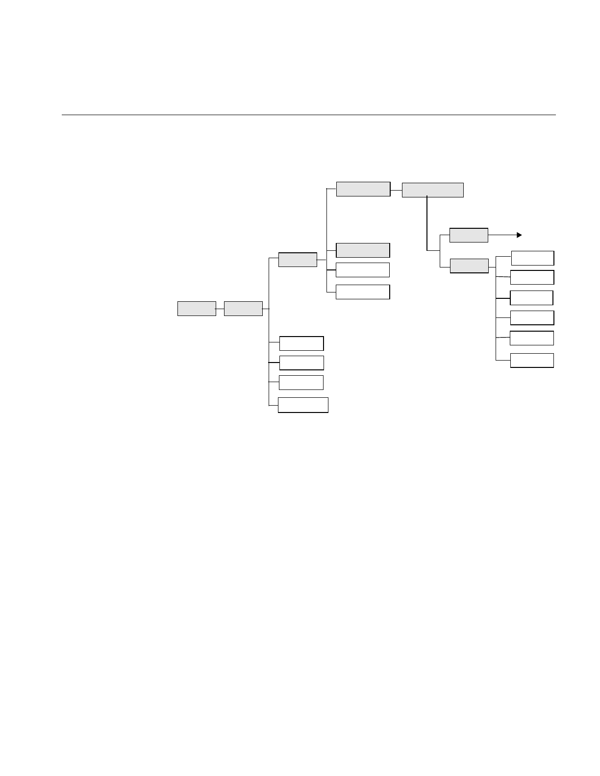
17
Figure 2-1 The ilLink Class Inheritance
The foundation classes shown in shaded boxes in Figure 2-1 are abstract classes and
cannot be used directly. Understanding the capabilities these classes provide is key to
understanding how the IL works and how to use it. Also, if you extend the IL to meet
your specific image processing needs, you will derive your own classes from these
abstract classes.
The ilLink Class
The IL allows you to access, manipulate, store, and display images. You can perform a
series of operations on one or more images by creating a chain of operators and passing
the image or images down this chain. An operator is a class derived from ilOpImg (the
base class for all IL operators) that applies its image processing algorithm to an image.
The image output from each operator becomes the input to the next operator in the chain.
ilLink
ilImage
ilImgStat
ilRoi
ilView
ilCacheImg
ilConstImg
ilRoiImg
ilMemoryImg
ilOpImg
ilFileImg ilFITImg
ilSGIImg
ilPCDImg
ilTIFFImg
Operator
classes
ilGIFImg
ilMemCacheImg
ilSwitchImg
ilPCDOImg
iflListItem
18
Chapter 2: The ImageVision Library Foundation
An element in a chain of operators can be:
•an image file, for example, an ilFileImg object
•a processing operation, which generates an image from one or more input elements,
for example, an ilAddImg object
•an object containing statistical information about an image, for example, an
ilImgStat object
•a region of interest (ROI), used to restrict the scope of an operator to a sub-portion
of its input elements, for example, an ilRectRoi object
•a subsection element, which selects a portion of its input(s) to be produced as an
output, for example, an ilSubImg or ilSwitchImg object
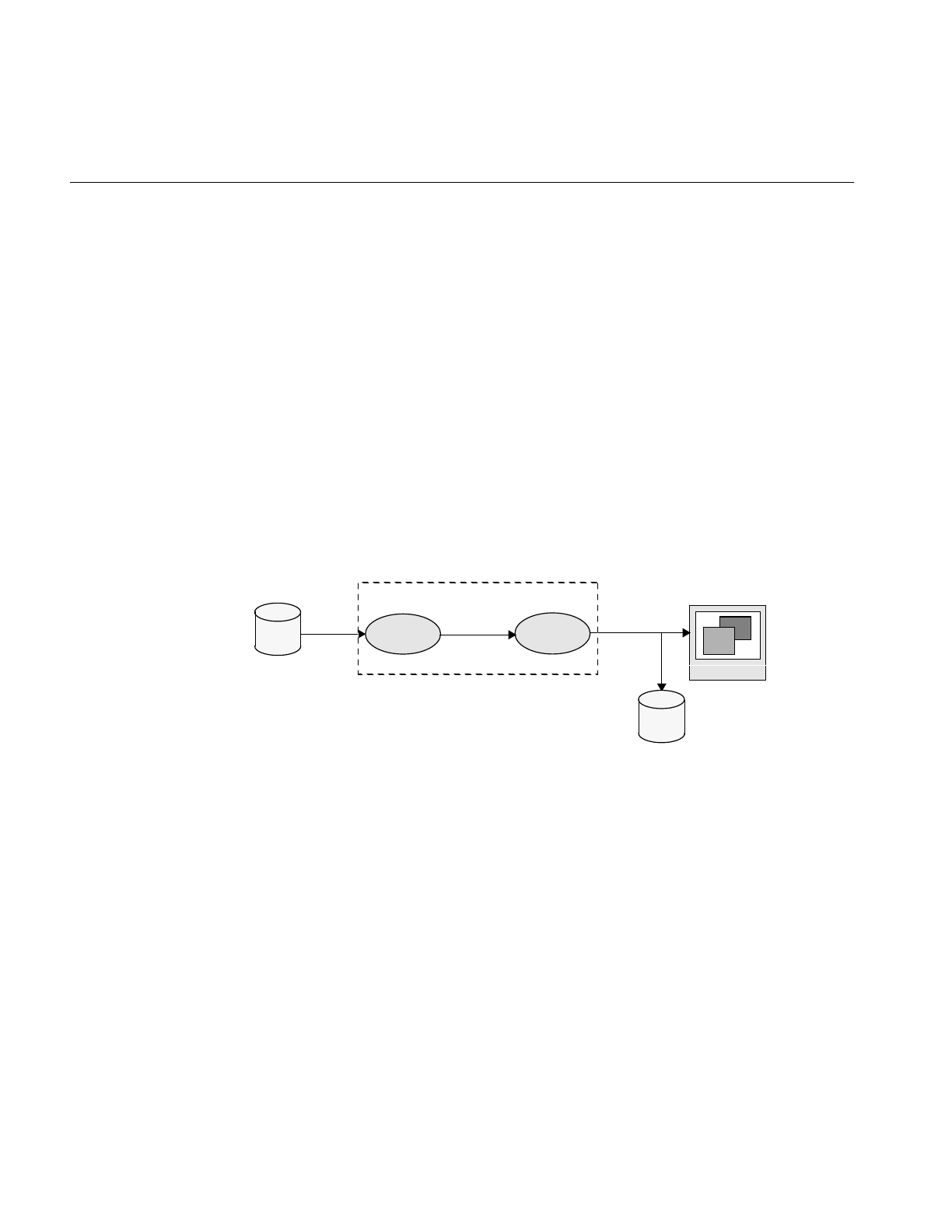
The result of a chain of operations is either a display of the processed image or a file on
disk containing the processed image. Figure 2-2 illustrates this concept by showing a
generalized image processing chain whose elements are raw and processed images.
Figure 2-2 An IL Chain
The ilLink class implements the chaining model by defining the mechanism for linking
the image objects together. This model defines the concept of parent (input) and child
(output) images.
The ilLink class also provides functions that allow you to manipulate image attributes by
providing functions that keep track of whether an attribute is allowed to change or has
been altered. For more information about chaining operators, see “The IL Execution
Model” on page 50.
monitor
raw
image
processed
disk operator1 operator2 processed
image image
IL chain
disk

Foundation Classes
19
The ilImage Class
The ilImage class is the root for the majority of the IL’s image class hierarchy. It provides
the IL’s abstract concept of what images are and how they are manipulated. The IL
defines an image as a four-dimensional array of pixels, x,y,z, and c. An image has certain
attributes, such as the size (in pixels) of the image, the data type of the pixel elements (for
example, float or int), and the color model that should be used to interpret the data (for
example, RGB or CMYK).
The ilImage class provides two main categories of functions to support this abstraction
of an image:
•image attribute functions, for querying an image about its attributes and setting
these attributes (Programmers can explicitly set some attributes, even though many
attributes are determined at the time the image is instantiated.)
•data access functions, for reading, writing, and copying image data
All classes that derive from ilImage (see Figure 2-1) inherit these general capabilities for
querying and setting attributes and accessing data. Thus, the IL allows you to
manipulate all images in the same way, regardless of the actual source or destination of
the data. The same mechanism is used for data that is associated with any type of image,
for example:
•an image stored in memory (ilMemoryImg)
•an image that is displayed on the screen and that resides in the framebuffer
(ilFrameBufferImg)
•an image operator, which applies an image processing algorithm to its data
(ilOpImg)
•an image that resides in a file on disk and is buffered in memory (ilFileImg)
Classes derived from ilImage implement their own versions of the data access functions
as necessary to add specificity. For example, ilMemCacheImg defines versions of the data
access functions that read data from or write data to a partial copy of the image buffered
in main memory. Similarly, ilTIFFImg adds capabilities specifically for reading and
writing TIFF file headers and data. The ilSharpenImg class incorporates a sharpening
algorithm into its access functions.

20
Chapter 2: The ImageVision Library Foundation
Image Attributes
In the IL, an image has many descriptive attributes. These include:
•image size
•data type of image pixels
•data ordering of channels in an image
•color model
•color palette
•image type
•orientation
•fill value
•minimum and maximum pixel values
•data compression
•page border
•image format
Many of these attributes are assigned default values when an image is created. Some of
them are changed subsequently, usually as a result of applying—or preparing to apply—
an image operator. Some can be changed explicitly by the programmer. Each class that
derives from ilImage chooses which attributes it allows to be explicitly modified. (For
more information about how this mechanism works, see “Propagating Image Attributes”
on page 59 and “Managing Image Attributes” on page 207.)
This section describes the image attributes and the functions available for retrieving and
setting them. These functions are defined by the ilImage and ilLink classes and therefore
can be used on any type of image.

Image Attributes
21
Table 2-1 provides a summary of the image attribute functions. All of these functions are
described later in this section except for the image format (described in “Querying a File
Image” on page 76) and the page border (described in “Page Borders” on page 56).
In addition to the functions shown above, which allow you to set image attributes
individually, you might decide to use the IL’s ilConfig class, which allows you to specify
several image attributes at once. An ilConfig object contains several elements that
Table 2-1 Image Attribute Summary
Image Attribute Retrieving Attributes Changing Attributes
Size getSize()
getXsize()
getYsize()
getZsize()
getCsize()
setSize()
setCSize)
Apply an operator that affects the size.
Data type getDataType()
isSigned()
setDataType()
Data ordering getOrder() setOrder()
Color model getColorModel() setColorModel()
Color palette getColorMap() setColorMap()
Orientation getOrientation() setOrientation()
Fill value getFill() setFill()
Min and max pixel
values
getMinPixel()
getMaxPixel()
getMinValue()
getMaxValue()
setMinPixel()
setMaxPixel()
setMinValue()
setMaxValue()
Min and max scale
values
getScaleMin()
getScaleMax()
setScaleMinMax()
initScaleMinMax()
setScaleType()
Data compression getCompression() setCompression()
Page border getPageBorder() setPageBorder()
Image format getImageFormat() Use the imgCopy utility to convert from
one IL-supported format to another

22
Chapter 2: The ImageVision Library Foundation
describe pixel data: the data type, pixel ordering, number of data channels, ordering of
data channels, channel offset, orientation, and zoom factors. This class is defined in the
header file il/ilConfig.h and described in more detail in “iflConfig” on page 359 as well as
in its reference page.
Error Codes
As you read the following sections, you will note that many of the functions described
return a value of data type ilStatus. This enumerated type, which is defined in the header
file il/ilError.h, contains the error codes used by the IL to indicate that an unexpected
result occurred. If no unexpected result occurred, an image’s status is ilOKAY. The error
codes and their meanings are listed in “Error Codes” on page 366.
At any point, you can query an ilImage about its current status by using getStatus(), a
function defined in ilLink that takes no arguments and returns a value of type ilStatus.
You can also set an image’s status to ilOKAY by using clearStatus() (a function defined
in and inherited from ilLink).
Size
One key attribute of an image’s its size, which is determined initially when an image is
created. In Example 1-1 in Chapter 1, “Writing an ImageVision Library Program,” the
size of the image data is determined when the ilFileImgOpen() function is called. An
image’s size can be described with an iflSize data structure, which consists of four
integers that correspond to the image’s size in the x,y, and z dimensions and the number
of data channels, c, per pixel.
The x and y dimensions specify the width and height of the image as measured in pixels.
The z dimension, or “depth,” may refer to the number of xy planes of image data. The xy
planes are usually related in some way; for example, they might be a time-series of a
single animation scene or a set of CAT scan images. (CAT stands for computerized axial
tomography, a medical imaging technique used to create three-dimensional images.)
Different image representations require different numbers of data channels to describe
each pixel of data. An RGB (red, green, blue) image, for example, requires three channels,
one for each of the three colors.

Image Attributes
23
The ilImage class defines functions for retrieving the entire iflSize structure for an image
at once and functions for returning each of the elements separately:
ilImage myImg;
iflSize imgSize;
int imgXSize, imgYSize, imgZSize, imgChans;
myImg.getSize(imgSize);
imgXSize = myImg.getXsize();
imgYSize = myImg.getYsize();
imgZSize = myImg.getZsize();
imgChans = myImg.getCsize();
You can change an image’s size by applying an image operator that affects its size or by
setting its size explicitly (if you are allowed to set it). For example, in most cases, the
ilRotZoomImg operator produces a processed image with a size that differs from that of
the original image, as shown in Figure 2-3:
Figure 2-3 Sizes of Original and Processed Images
You can set an image’s size explicitly by using setSize(), which takes a reference to the
desired iflSize structure as an argument. A separate function, setCsize(), allows you to
restrict the number of channels associated with an image.
Data Type
An image’s pixel components must all be of the same data type. The IL defines an
enumerated set of data types (iflDataType) and a function, getDataType(), to return the
data type of an image’s pixels:
iflDataType imgType;
imgType = myImg.getDataType();
The iflDataType returned can be one of the following: iflBit, iflChar, iflUChar (an
unsigned char), iflShort, iflUShort, iflLong, iflULong, iflFloat, or iflDouble. (These types
Original Rotated Image
New Size
Image Zoomed Image
New Size

24
Chapter 2: The ImageVision Library Foundation
are defined in the il/iflDataTypes.h header file and listed in “Describing Image Attributes”
on page 370.)
Use isSigned() to query an ilImage about whether its data type is signed:
int sign = myImg.isSigned();
As shown, this function takes no arguments and returns TRUE (nonzero) if the image’s
data type is signed and FALSE (zero) otherwise.
Operators accept input images of any data type. Internally, however, operators may use
a different data type than the input data type to process the image. In this case, the data
is converted as needed to perform the computation. If you know what data type you
need at the end of the computation, you can use the setDataType() function to force the
data type.
Data Ordering
The channels composing an image’s pixel data can be ordered in three ways:
iflInterleaved, iflSequential, or iflSeparate. These are the three possible return values of
the enumerated type, iflOrder. To return the data ordering, use its member function,
getOrder(), as follows:
iflOrder imgOrder;
imgOrder = myImg.getOrder();
The meanings of the three orders are illustrated in Figure 2-4.
Figure 2-4 Pixel Data Ordering for an RGB Image
Interleaved In interleaved ordering, all pixel components are clustered together. For
an interleaved RGB image, data is stored as: RGBRGBRGB....
Sequential With sequential ordering, each component is stored as a separate line. In
the example, three lines of data (one each for red, green, and blue data)
are needed to describe one line of pixels.
iflInterleaved iflSequential iflSeparate
RGB
RGB
RGB RRR
GGG
BBB
RRR GGG BBB
RRR
RRR
GGG
GGG
BBB
BBB

Image Attributes
25
Separate An image using separate ordering stores each component in a separate
page. (See “The Cache” on page 32 for more information about pages.)
Thus, the order defines that dimensions that vary most rapidly relative to the others in a
chunk of data. For example, in the interleaved case, the channel dimension varies most
rapidly, and the z dimension varies least rapidly. Here is how the dimensions vary for
each of the orders, listed from most to least rapidly: iflInterleaved (c,x,y,z), iflSequential
(x,c,y,z), iflSeparate (x,y,z,c).
In the rare cases where you need to set an image’s order, use the setOrder() function.
Some classes derived from ilImage, such as ilFileImg, do not let you change an image’s
order.
Color Model
An image’s color model determines the meaning of the data channels from which a pixel
is constructed. The IL defines an iflColorModel enumerated type (in the header file
il/iflDataTypes.h) that can refer to the following color models:
iflRGB red, green, blue
iflRGBA red, green, blue, alpha
iflRGBPalette color index mapped to an RGB lookup table
iflHSV hue, saturation, value
iflCMY cyan, magenta, yellow
iflCMYK cyan, magenta, yellow, black
iflMinWhite grayscale, with the minimum value interpreted as white
iflMinBlack grayscale, with the minimum value interpreted as black
iflBGR variation of RGB, for images generated by Silicon Graphics
iflABGR variation of RGBA, for images generated by IRIS GL
iflMultiSpectral
generally more than three channels; requires a special interpretation
iflYCC a luminance/chrominance data metric based on video primaries
The getColorModel() function allows you to query an image about its color model. If
necessary, you can change the data interpretation by using the setColorModel() function.
26
Chapter 2: The ImageVision Library Foundation
Determining the Color Model
If an application or derived class does not use the setColorModel() function to explicitly
set the color model of an ilOpImg object, the color model defaults to the lowest common
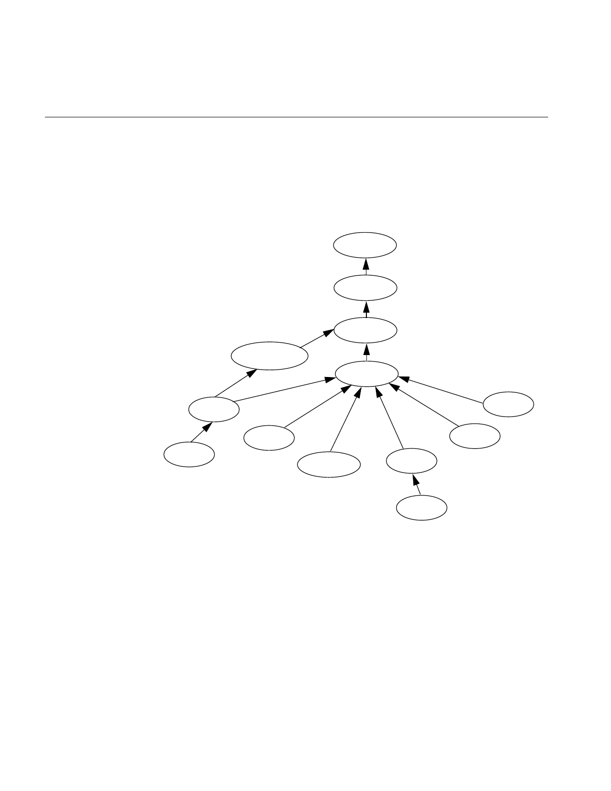
ancestor of the input images as shown in Figure 2-5:
Figure 2-5 Determining Color Model Inheritance for Operator Images
Determining Operator Data Types, Ordering, Working Types, and
Definable Fields
All classes derived from ilOpImg have specified output data types, data ordering,
working data types, and fields that can be set on an object. You can identify them by
finding the following functions in each class: setValidType(), setValidOrder(),
iflMultiSpectral
iflRGBA
iflABGR
iflRGB
iflRGBPalette
iflHSV
iflLuminence
iflCMYK
iflYCC
iflNegative
iflBGR
iflCMY
iflLuminanceAlpha

Image Attributes
27
setWorkingType(), and setAllowed(), respectively. For example, the ilWarpImg operator
uses an iflUChar as the output data type, can use any output ordering, uses iflFloat as the
working type, and can have any of its fields set.
You can set the data type or data order explicitly to a valid type or ordering by calling the
ilImage member function setValidType() or setValidOrder(), respectively. If the data
type or order is not set explicitly in this manner, they default to the “smallest” of the valid
types or ordering that is at least as “great” as each input type or order. Here “small” and
“great” refer to the numeric values of the types and ordering, as defined in
il/iflDataTypes.h.
An ilOpImg object has a “working type”, which is the data type used for calculations.
The working type is often the same as the output data type. When this is not the case, the
setWorkingType() function is used to define the working types.
The setAllowed() function specifies which fields can be set on an object that is an
instance of a class derived from ilOpImg.
Color Palette
Some images include a color palette that is used to interpret their data. A color palette is
also referred to as a lookup table or LUT. The most common use of such a table is to store
color map values. The iflLut class, defined in the header file ifl/iflLut.h and described in
“Using iflLut” on page 360, is provided for such purposes. To set an image’s LUT, use
setColorMap():
ilStatus setColorMap(const iflLut& lut);
The table pointed to by lut is established as the image’s look-up table. This function
copies the specified iflLut but not its data. The getColorMap() function returns by
reference an image’s LUT:
void getColorMap(iflLut& lut);
Two other functions—iflSGIColormap() and ilSGIFileLut()—create look-up tables for
use in managing color map data. They are described in “Using iflLut” on page 360 and
in their own reference pages.

28
Chapter 2: The ImageVision Library Foundation
Orientation
Different file formats arrange their data in different ways. By default, a TIFF file image
considers its origin to be the upper left corner; if you scan through the data, you should
read from left to right, working your way down the image. An SGI RGB image considers
its origin to be the lower left corner; to read through its data, again read from left to right,
but work your way up the image.
The IL defines an iflOrientation data type to represent the possible orientations of image
data. To query an image about the orientation of its data, use getOrientation(), which
returns one of the eight values listed below. (You can set an image’s orientation with the
setOrientation() function.) These four orientations use the traditional orientation of the
x and y dimensions (the x dimension runs horizontally, and the y dimension runs
vertically):
The following four orientations have the x and y dimensions transposed so that the x
dimension runs vertically, and the y dimension runs horizontally.
iflUpperLeftOrigin The origin is in the upper, left corner and you read data from
left to right, working your way down the image
iflLowerLeftOrigin The origin is in the upper, left corner and you read
data from left to right, working your way up the
image
iflUpperRightOrigin The origin is in the upper right corner, and you read data
from right to left, working your way down the image
iflLowerRightOrigin The origin is in the lower right corner, and you read
data from right to left, working your way up the
image
iflLeftUpperOrigin The origin is in the upper left corner, and you read
from top to bottom, working your way across the
image to the right.
iflLeftLowerOrigin The origin is in the lower left corner, and you read
from the bottom to the top, working your way across
the image to the right.
iflRightUpperOrigin The origin is in the upper right corner, and you read
data from top to bottom, working your way across the
image to the left.
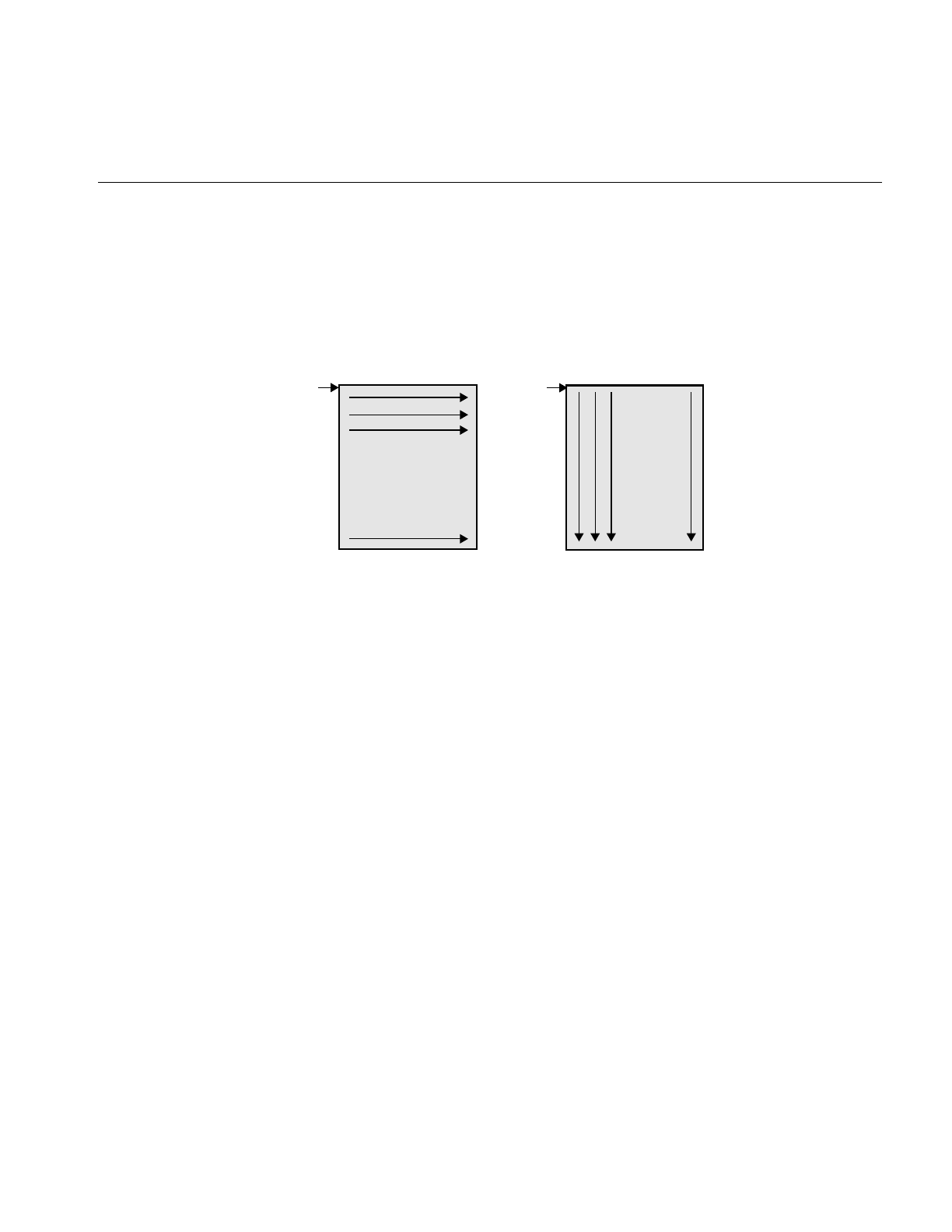
Image Attributes
29
Figure 2-6 illustrates the difference between iflUpperLeftOrigin and iflLeftUpperOrigin
orientation of image data.
Figure 2-6 Image orientations
Fill Value
When a function tries to access pixels that are beyond an image’s edge, those pixels are
set to the image’s fill value. By default, an image’s fill value is 0, but you can set a
different fill value with the setFill() function:
static float fillData[3] = {127.0, 127.0, 127.0};
myImg.setFill( iflPixel(iflFloat, 3, fillData) );
As shown, setFill() takes a reference to an iflPixel as an argument. An iflPixel defines the
pixel is data type (in this case, iflFloat), the number of data channels (3), and the pixel
data itself (fillData[]). (In this example, the iflPixel value is passed in-line so that the
compiler automatically constructs and deletes the object.) The image makes its own copy
of the pixel data.
Use getFill() to query an image about its fill value:
iflPixel theFillValue;
myImg.getFill(theFillValue);
iflRightLowerOrigin The origin is in the lower right corner, and you read
data from bottom to top, working your way across the
image to the left.
. . .
iflUpperLeftOrigin iflLeftUpperOrigin
Origin
Origin
.
.
.

30
Chapter 2: The ImageVision Library Foundation
Creating Fill Values
You use the allocFillData() and freeFillData() functions in the ilImage class to create and
free fill values in the native image format from an RGB triplet. The functions are defined
as follows:
void* allocFillData(float red, float green, float blue);
void freeFillData(void* data);
Minimum and Maximum Pixel Values
By default, no restrictions are placed on the range of allowable pixel values. However,
when an image is displayed—for example, using the ABGR color model—its pixel values
may need to be converted to the range that is meaningful for the framebuffers, which is
0 to 255. If you explicitly set an image’s minimum and maximum allowable pixel values,
they are used to color-scale the data as it is displayed.
You might want to set the allowable pixel values for a processed image so that the
resulting data has certain characteristics, especially if you display the data. For example,
suppose you are using an edge detection filter that theoretically produces data ranging
in value from -1000 to +1000. However, you know that the images you’ll be filtering will
actually yield filtered data ranging from -100 to +100. If you set the allowable values to
match this range and then display the filtered data, the display will be more useful, since
the data will be scaled and stretched out over the framebuffer is meaningful range.
Setting Maximum and Minimum Pixel Values
Minimum and maximum values are image attributes that are stored with an image. You
can set the minimum and maximum allowable values for an image’s pixel data by using
the setMinPixel() and setMaxPixel() functions. Both these functions take an ilPixel
reference as an argument:
ilStatus setMinPixel(const ilPixel& pix);
ilStatus setMaxPixel(const ilPixel& pix);
Use getMinPixel() and getMaxPixel() to query an image about its minimum and
maximum allowable pixel values:
void getMinPixel(ilPixel& pix);
void getMaxPixel(ilPixel& pix);
These functions return the minimum or maximum pixel value by reference.

Image Attributes
31
Setting Maximum and Minimum Pixel Values for a Channel
You can also set the minimum and maximum values for an individual channel of an
image:
ilStatus setMinValue(double val, int c=0);
ilStatus setMaxValue(double val, int c=0);
These functions set channel c’s minimum or maximum value to val.
To query an image about its channel value limits, use getMinValue() and getMaxValue():
double getMinValue(int c=-1);
double getMaxValue(int c=-1);
These functions return the minimum or maximum allowable value for the specified
channel (the default, -1, returns the minimum or maximum of all channels).
Setting Maximum and Minimum Scaling Values For Color Conversion
Minimum and maximum scaling values are used by the IL during color conversion. By
default, the scale minimum and maximum are the same as the image minimum and
maximum values. The IL provides functions you can use to set and retrieve maximum
and minimum scaling values.
The initScaleMinMax() function initializes the scale minimum and maximum to the
image minimum and maximum values. If scale minimum and maximum have already
been set, they are unchanged, unless force is TRUE.
void initScaleMinMax(int force=0);
The function setScaleMinMax() sets the minimum and maximum scaling values to min
and max. The setScaleType() function sets the scale minimum and maximum to the
minimum and maximum values of the data type passed in type.
ilStatus setScaleMinMax(double min, double max);
ilStatus setScaleType(iflDataType type = iflDataType(0));
The getScaleMax() and getScaleMin() functions return the maximum and minimum
values used for scaling during color conversion.
double getScaleMax();
void getScaleMin();

32
Chapter 2: The ImageVision Library Foundation
Data Compression
Often, images stored in a file on disk are compressed to minimize their size. Such images
need to be decompressed before they can be read. There are many different compression
algorithms. Each file format (for example, TIFF) determines which algorithms it
supports. See “Setting a File’s Compression” on page 75 for more information about
which compression algorithms the IL supports. From a programmer’s point of view, as
data is read or written in an IL program, its compression or decompression is handled
transparently.
The Cache
The IL uses the term cache to mean a portion of memory that holds raw and processed
image data that can be accessed by a process. This is not the same as the hardware cache
that is accessed by the CPU. The IL cache holds image data in rectangular pieces called
pages. The cache does not necessarily hold all the pages for each image being processed,
but only those pages that have been referenced and have not been bumped out of the
cache to make room for more recently-referenced pages. Thus, only part of an image may
reside in the cache.
Figure 2-7 shows a cache that contains three images being used by an IL application. The
three rectangles on the left show a logical map of the pages for each image. The shaded
boxes indicate the pages of each image resident in the cache. For example, the raw image
contains four pages, only two of which are in the cache. The rectangle on the right shows
the cache as it might contain the pages from the three images.
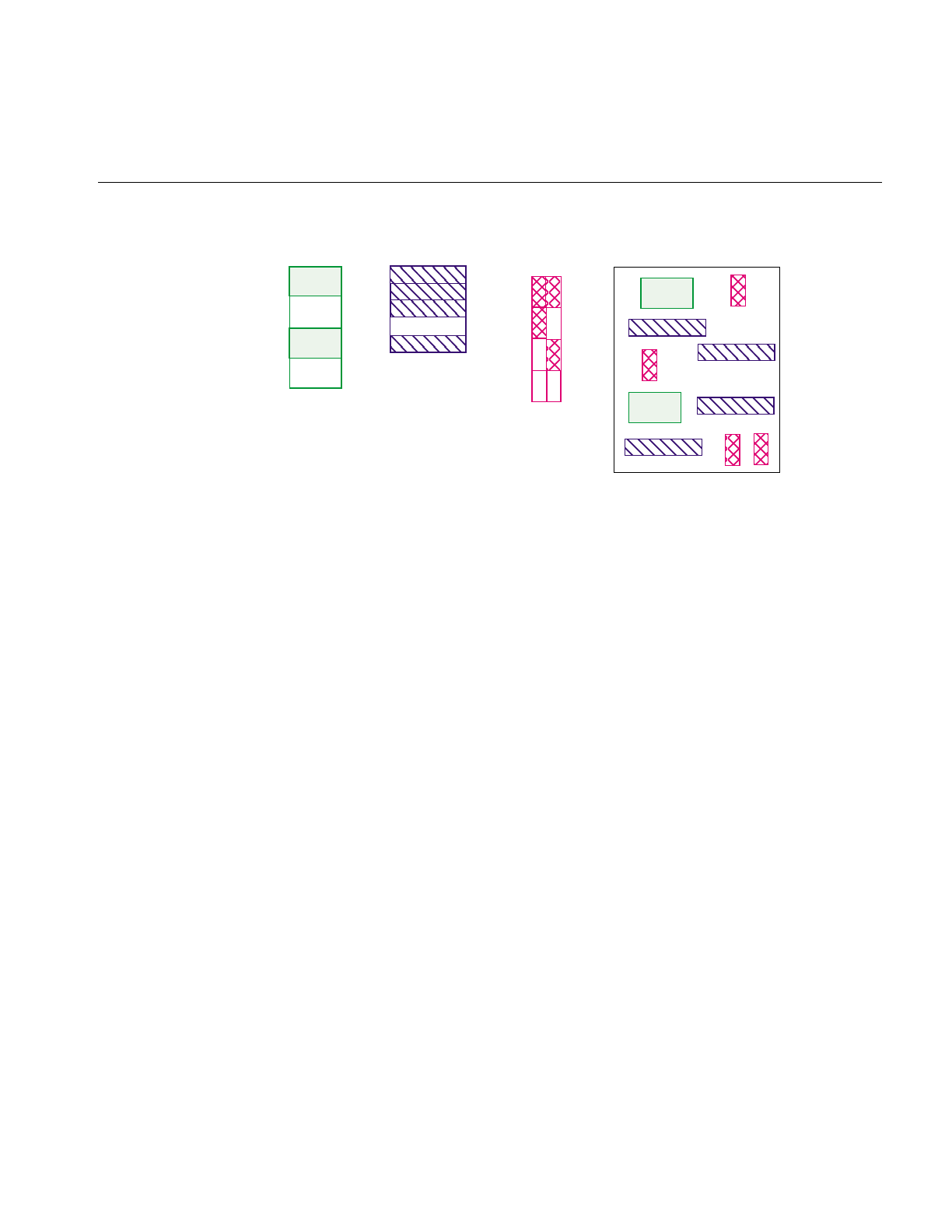
The Cache
33
Figure 2-7 Cache Containing Portions of Three Images
The IL keeps track of the pages in the cache, brings in a page when the program requests
data on a page not in the cache, and chooses a page to be overwritten when additional
room is needed in the cache.
Every IL class that derives from ilMemCacheImg uses the cache and the caching
mechanism defined by ilMemCacheImg. Both ilOpImg and ilFileImg inherit directly
from ilMemCacheImg and use caching in these ways:
•IL operators (those classes that derive from ilOpImg) use the cache to hold their
output.
•Classes that derive from ilFileImg place raw, uncompressed data in the cache.
While the cache holds image data in pages, an IL program can access image data in
rectangular blocks of any size, without regard to page boundaries. These rectangular
blocks are referred to as tiles. As shown in Figure 2-8, tiles can cross page boundaries or
can be smaller than a page.
Raw Image Processed Image Processed Image
1
2
3
4
1
1
1
12
2
2
3
3
4
4
2
12
3
4
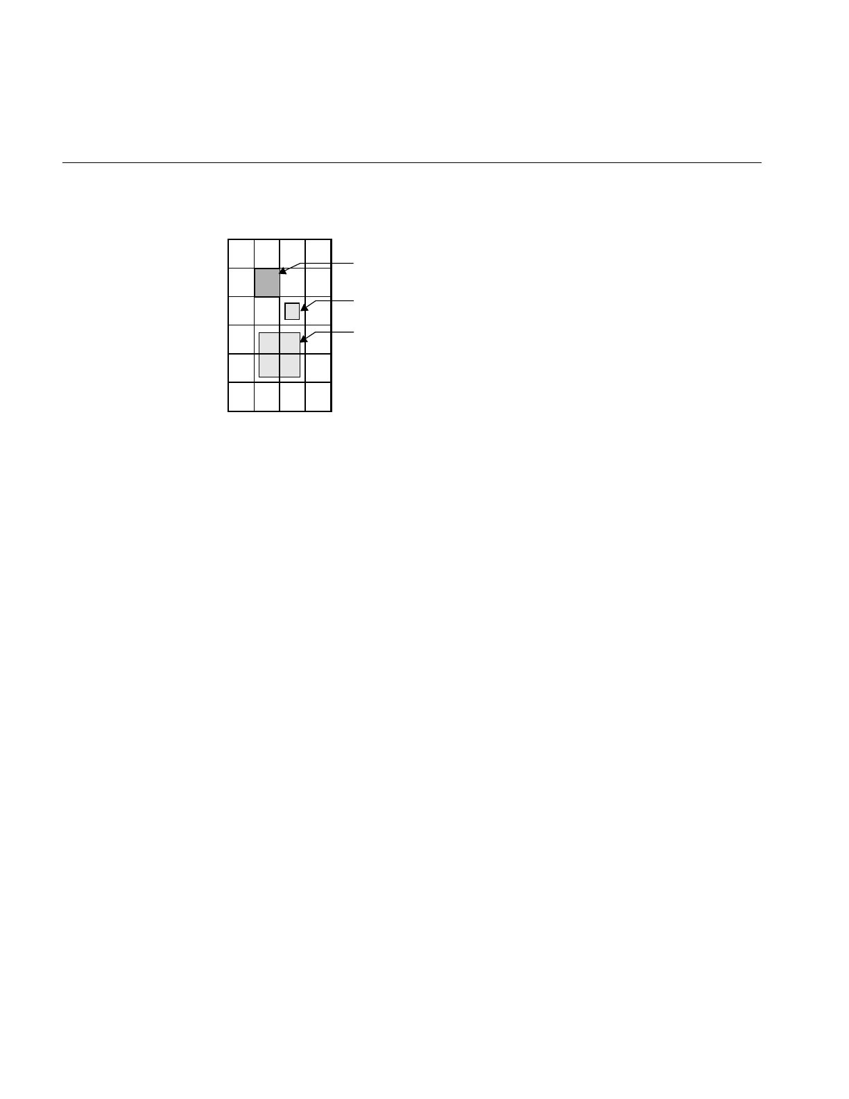
34
Chapter 2: The ImageVision Library Foundation
Figure 2-8 Pages and Tiles of Image Data
When a program requests a data tile, the IL checks the cache. If the data corresponding
to the tile is not among the pages already in the cache, the IL brings additional pages into
the cache as necessary. If the cache is already full, it must discard some of the resident
pages in order to make room for the new pages. The page replacement algorithm is based
on a combination of the following factors:
•The number of times each page has been referenced; the more times a page is
referenced, the more likely it will remain in the cache.
•The priority of the references; higher priority requests tend to have their pages
retained longer.
•The relative time since each page was last referenced; the pages that have been in
the cache the longest without being referenced are discarded first.
The overall effect of the page replacement algorithm is that data toward the end of a
chain tends to get preferentially cached. Other data that is frequently referenced (for
instance, the input to an operator whose parameters are being repeatedly adjusted) also
tends to remain in the cache. To prevent data from being recomputed for successive tile
requests, the cache must be large enough so that pages just discarded aren’t reread. (See
the following two sections for more information on setting the size of the cache and
adjusting priorities.)
Since operators place processed image data in the cache, data is operated on as it is
brought into the cache. To maximize efficiency under this execution model, only the
pages needed to satisfy any given tile request are brought into the cache. For example, if
agetTile() request specifies only a single channel of an image that is stored in a separate
format, only the pages containing that channel are accessed. Thus, processing
Image
Page
Tile
Tile

The Cache
35
multispectral data (or any data stored in a separate format) is made as efficient as
possible.
Managing Cache
By default, the cache size is set to 30% of the total user memory on the host system. The
IL provides two functions to override the default size of the cache, ilSetMaxCacheSize()
and ilSetMaxCacheFraction(), which are defined as shown below:
void ilSetMaxCacheSize(int maxBytes);
void ilSetMaxCacheFraction(float fraction);
The first function sets the cache size to the number of bytes indicated. The second
function computes the size of the cache as the indicated fraction of the total user memory
on the host computer.
You can change these limits without modifying an IL- based program by using the
environment variables IL_CACHE_SIZE or IL_CACHE_FRACTION to set either the size
in bytes or the fraction of user memory, respectively. The IL_CACHE_SIZE value
overrides the value specified by IL_CACHE_FRACTION. Any value established with
these environment variables is overridden by calls to ilSetMaxCacheSize() or
ilSetMaxCacheFraction().
The current value of these cache size limits can be obtained with either
ilGetMaxCacheSize() or ilGetMaxCacheFraction(). The current actual size of the object
is cache can be retrieved with ilGetCurCacheSize(). These functions are defined as
follows:
int ilGetCurCacheSize();
int ilGetMaxCacheSize();
float ilGetMaxCacheFraction();
The IL maintains the global cache in a special memory pool that allows the cache
memory to be compacted to eliminate memory fragmentation problems. When
fragmentation exceeds a defined threshold, the pool is automatically compacted. You can
use the ilSetCompactFraction() function to set the fragmentation threshold to the
maximum fraction of the pool that is allowed to be wasted space before compaction
occurs. The current value of this threshold can be obtained with
ilGetCompactFraction(). The default compaction fraction value is .2 or 20%.
ilSetCompactFraction(float maxWastedFraction);
float ilGetCompactFraction();

36
Chapter 2: The ImageVision Library Foundation
You can force compaction of the pool at any time by calling ilCompactCache(). If the pool
is more fragmented than the fraction passed to this routine, it is compacted. You can pass
zero to cause the pool to be unconditionally compacted.
ilCompactCache(float maxWastedFraction=0);
You can use the getCacheSize() function of ilMemCacheImg to query the cache size for
an individual object:
int getCacheSize();
You can use the flush() member function of ilMemCacheImg to flush the cache for an
individual object:
ilStatus flush(int discard=FALSE));
You can free the memory in the global cache to get it down to a desired maximum size
with ilFlushCache(). This call also compacts the cache memory.
int ilFlushCache(int maxsize);
Priority
The IL assigns priorities to pages in the cache and uses these priorities to make decisions
about which pages to discard. The priority associated with pages in cache ranges from
zero (lowest) to seven (highest); the higher the priority, the greater the likelihood the
page will remain resident.
The IL maintains a linked list of the pages in cache for each of priority levels 0 through
7. Figure 2-9 illustrates this concept. This simplified diagram shows a cache with three
pages at priority level seven, two pages at priority level three, and three pages at level
zero.
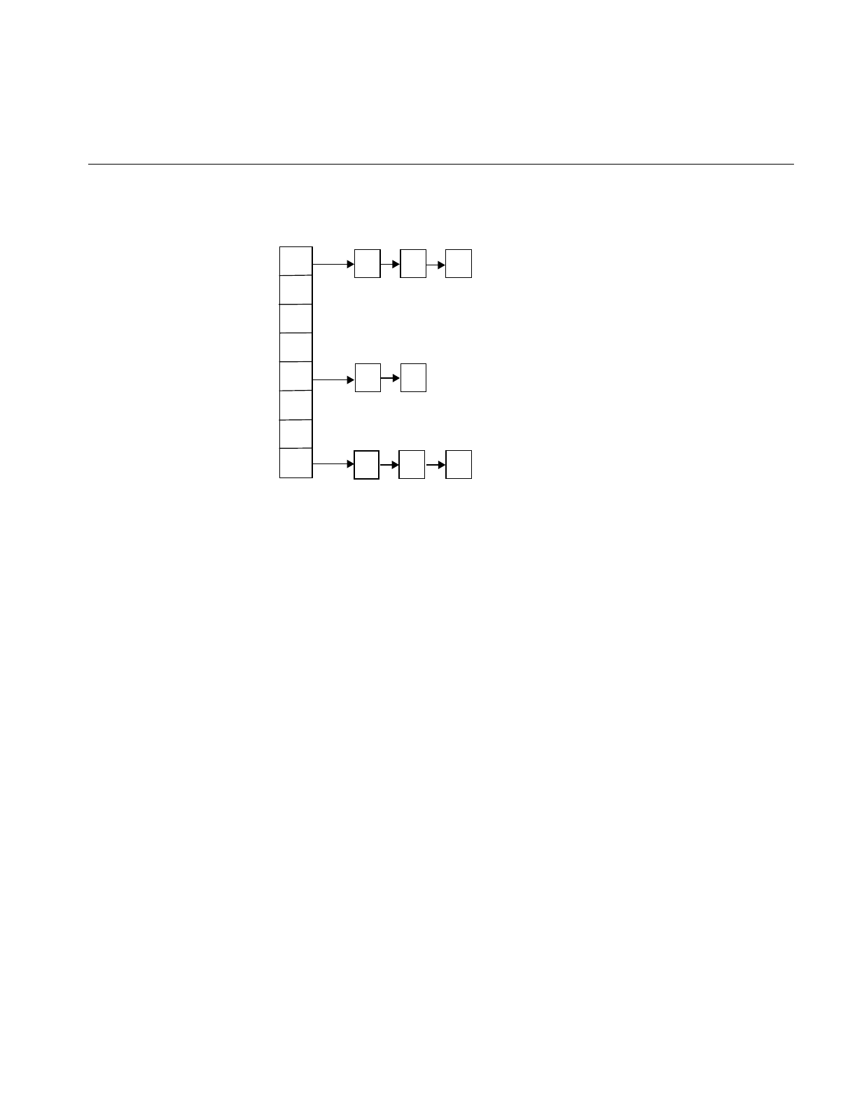
The Cache
37
Figure 2-9 Priority Lists in Cache
The initial (default) priority level of a page is zero. The following events can cause a
change to the priority level:
•The priority of a page is incremented each time the page is accessed (for example by
acopyTile() or ilMemCacheImg::executeRequest()). This is essentially a reference
count; the more times a page is referenced, the higher its priority.
•The priority of the page is incremented when you use the lockPage() method to lock
a page.
•If you use the setPriority() method to set the priority of the image containing the
page, the IL increases the priority of the page by one plus the value specified in
setPriority() each time the page is referenced. The setPriority() definition is shown
below:
void setPriority(int priority);
•The maximum number of pages at each priority level is one eighth of the total
number of pages in cache. If the number of pages at any one priority level exceeds
this limit, the priority level of the last page at that level is reduced by one. In other
words, the page is moved to the head of the list at the next lower priority level.
You can use the ilmonitor utility to monitor the activity of pages in cache. See the ilmonitor
reference page or “Image Tools” on page 277 for more information about ilmonitor.
0
1
2
3
4
5
6
7
Priority level Pointers to pages in cache

38
Chapter 2: The ImageVision Library Foundation
Page Size
The page size for each operator is defined by its input images. For an ilFileImg, the page
dimensions match those used to store the image on disk. Some images also let you set the
size of the pages in the cache, the data type, and the ordering of the cached data. The data
type and ordering affect how data is cached, so if you change these attributes, you might
also want to change the size of the cache. To set the data type or the ordering of data in
the cache, use the appropriate functions defined by ilImage, setDataType() and
setOrder(). These functions are described in “Image Attributes” on page 20. “Managing
Cache” on page 35 describes how to set the size of the cache.
Only image operators allow you to set the page size of an image. If you change the page
size of an image, you should follow the suggestions in “Cache Priority” on page 250.
To set the size of the pages used in the cache for a particular image, use setPageSize(),
which is defined in the ilImage class as follows:
ilStatus setPageSize(int nx, int ny, int nz, int nc)
{ return setPageSize(iflSize(nx, ny, nz, nc)); }
ilStatus setPageSize(const iflSize& pageSize);
ilStatus setPageSize(int nx, int ny);
The following functions are related:
ilStatus setPageSizeZ(int nz);
ilStatus setPageSizeC(int nc);
The arguments specify the x, y, z, and cdimensions of the page in pixels. This function
calculates the number of bytes needed to store a page with the specified dimensions.
You can use any of the following functions to query an image about its page size,
depending on whether you want the answer in page dimensions, bytes, or pixels:
size_t getPageSize();
size_t getPageSize(int& nx, int& ny, int& nz, int& nc);
size_t getPageSize(int& nx, int& ny)
size_t getPageSize(iflSize& pageSize, iflOrientation workOrientation);
size_t getPageDimensions(iflSize& pageSize)
int getPageSizePix();
int getPageSizeVal();
getPageSize() returns the page size in bytes; this function is overloaded, as shown, to
take no arguments or to take arguments that return the size and
orientation of the page in pixels.

The Cache
39
getPageSizePix()
returns the total number of pixels represented by a page; this value is
found by multiplying the x, y, and z dimensions.
getPageSizeVal()
returns the total number of data elements represented by a page; this
function multiplies the page’s channel dimension by the value returned
from getPageSizePix().
Multi-threaded Paging Support
The ilImage class provides functions to support paging in a multi-threaded environment.
These functions allow you to lock pages to ensure that those pages stay in memory until
you unlock them. The five virtual functions that control paging are:
virtual int hasPages();
virtual ilPage* lockPage(int x, int y, int z, int c,
ilStatus& status, int mode=ilLMread);
virtual void unlockPage(ilPage* page);
ilStatus lockPageSet(ilLockRequest* set,
int mode=ilLMread, int count=1);
void unlockPageSet(ilLockRequest* set, int count=1);
hasPages() returns TRUE for ilMemCacheImg and all of its descendants and FALSE
for all other classes in the IL. This function is useful for determining
whether the ilImage in question supports paging.
lockPage() locks down the page located at x,y,z, and c in the cache; it returns a
pointer to that page, which is later passed to unlockPage() to free up that
page.
unlockPage() frees the page specified by the pointer in the argument list.
lockPageSet() processes a set of ilLockRequest structures and returns pointers to the
requested pages in the structures.
unlockPageSet()
releases the set of pages obtained by the lockPageSet() function.
These methods provide a mechanism to bypass the overhead of getTile() and setTile(),
but they require that you consider all of the attributes of the page: size, data type, and
order.

40
Chapter 2: The ImageVision Library Foundation
Accessing Image Data
All classes derived from ilImage read, write, and copy image data using the same set of
data access functions defined by the ilImage base class. Each derived class implements
the functions as necessary to suit its particular requirements. A key feature of these
functions is that they allow you to access any arbitrary rectangle, or tile, of image data,
regardless of how that data is stored. This flexibility allows the IL is demand-driven
execution model to be implemented. As part of this model, calls to some of these
functions are generated automatically. However, you can also call these functions
explicitly as needed. The execution model is discussed in detail in “The IL Execution
Model” on page 50. The ilImage class defines both three-dimensional and, for
convenience, two-dimensional data access functions, as shown in Table 2-2.
The two-dimensional data access functions work through their three-dimensional
counterparts. Since the two-dimensional versions are slightly easier to comprehend, they
are discussed first, in the next section.
Two-dimensional Functions
The two-dimensional functions you are likely to use most frequently are getTile(),
setTile(), and copyTile(). As their names suggest, these functions read (get), write (set),
and copy a tile of data. They assume the data buffer being read into or written from is the
a. << is the left-shift or output operator; it is redefined in the C++ version of the IL.
Table 2-2 Data Access Functions
Three-dimensional Two-dimensional Description
getTile3D()
setTile3D()
copyTile3D() or <<a
copyTileCfg()
getTile()
setTile()
copyTile() or <<
reads, writes, and copies a tile of data
getSubTile3D()
setSubTile3D()
getSubTile()
setSubTile()
reads and writes a subtile of data
getPixel3D()
setPixel3D()
getPixel()
setPixel()
reads and writes a pixel
fillTile3D() fillTile() fills a tile with a constant value

Accessing Image Data
41
exact size necessary to hold the tile being read or written; if the buffer is larger use
getSubTile() or setSubTile().
Another pair of functions, getPixel() and setPixel(), allow you to read and write pixels
rather than tiles. The fillTile() function allows you to fill a two-dimensional tile of data
with a specified constant value.
getTile() and setTile()
The calling sequences for getTile() and setTile(), which take the same arguments, are
shown below:
ilStatus getTile(int x, int y, int nx, int ny,
void* data,const ilConfig* config=NULL);
ilStatus setTile(int x, int y, int nx, int ny, void* data,
const ilConfig* config=NULL);
getTile() retrieves a tile of data from a source image and places it in the location pointed
to by data. This source image is the one whose getTile() function is called. The tile that is
retrieved is specified by its origin in the source image (x,y) and its size (nx and ny), which
is measured in pixels. (Since the tile’s origin is specified in the image’s orientation, the
(x,y) point is specified relative to the image’s origin.) The optional config argument allows
you to change the configuration of the data (including the orientation) as it is read and
placed in the buffer. If this argument is not supplied, the configuration of the source
image is used. One element of an ilConfig object is an ordered list of the image’s channels.
See “copyTile()” on page 42 for an example of using this channel list to reorder channels
as data is retrieved.
The setTile() function writes a tile of data from the location pointed to by data to the
destination image. The location of the tile being written is specified by its origin in the
destination image (x,y) and its size (nx and ny). The optional config argument for setTile()
describes the configuration of the data being written; if necessary, the data is
automatically reconfigured to match the configuration of the destination image. If this
argument is not supplied, it is assumed that the data being written already has the same
configuration as the destination image.

42
Chapter 2: The ImageVision Library Foundation
copyTile()
The copyTile() function is an efficient way to copy a tile of data from one ilImage to
another:
ilStatus copyTile(int x, int y, int nx, int ny,
ilImage* image, int ox, int oy,
int* chanList=NULL);
The tile is copied to the location (x,y). (nx,ny) specifies the size of the tile. (ox,oy) specifies
the location in the source image from which the data is copied. (If the tile is at the same
location in both the source and destination images, then x=ox and y=oy.) If the source and
destination images have different orientations, the data is transposed automatically as
necessary.
No configuration argument is needed for copyTile() because the destination image’s
configuration is always used. Data is automatically converted as necessary to match the
destination image’s data type, order, and orientation. However, you can choose a subset
of the source image’s channels and/or reorder them using the optional chanList
argument. This argument is an int array that specifies a channel mapping between the
other image and the calling image. The number of entries in the array should always
match the number of channels in the calling image; a negative one (-1) in the array means
that no data will be written for that channel.
As an example, suppose you have an RGB image (with red, green, and blue channels)
that you want to display as an ABGR image (with alpha, blue, green, and red channels).
The code for accomplishing this conversion is:
/* allocate the data buffer */
int xsize = 20;
int ysize = 10;
char data[xsize*ysize*3];
/* specify the channel list and configuration */
static int chans[] = {3, 2, 1};
ilConfig config(iflUChar, iflInterleaved, 3, chans);
/* read the data from one image and write it to the other */
RGBImg.getTile(0, 0, xsize, ysize, data);
ABGRImg.setTile(0, 0, xsize, ysize, data, &config);
Note: You can do this conversion most simply with the color conversion operators that
derive from ilColorImg, but this example using getTile() and setTile() is presented for
discussion purposes.

Accessing Image Data
43
First, a buffer, data, is allocated to hold the 20-pixel by 10-pixel three-channel tile as it is
copied. Next, the configuration that the data should be mapped into is specified. The
channel list, chans, maps the channels of the RGB data to the channels of the ABGR image,
as follows:
•Channel 0 of the RGB data (the red channel) is mapped to channel 3 of the ABGR
image (also the red channel).
•Channel 1 of data (green) is mapped to channel 2 of the ABGR image (also green).
•Channel 2 of data (blue) is mapped to channel 1 of the ABGR image (blue).
•Nothing is available to map to channel 0 of the ABGR image (the alpha channel).
Finally, the data is read into the buffer from RGBImg and then it is written to ABGRImg
from the buffer.
The following code performs the same task using copyTile() instead:
int xsize = 20;
int ysize = 10;
static int chans[] = {-1, 2, 1, 0};
ABGRImg.copyTile(0, 0, xsize, ysize, RGBImg, 0, 0, chans);
In this case, an intermediate data buffer is not needed; the tile is copied directly from
RGBImg to ABGRImg. The channel list specifies how the channels of RGBImg are
mapped to those of ABGRImg, as shown in Table 2-3.
The interpretation of the channel list is the same if the direction of the copy is reversed.
If the same channel list were used with a call to copyTile() that specified 0 as the direction
argument, data would be copied from ABGRImg to RGBImg as follows:
•Channel 0 of ABGRImg is not copied at all.
Table 2-3 Channel Mapping
Channel List RGBImg Channel ABGRImg Channel
-1 none 0 (alpha)
2 2 (blue) 1 (blue)
1 1 (green) 2 (green)
0 0 (red) 3 (red)

44
Chapter 2: The ImageVision Library Foundation
•Channel 1 of ABGRImg is copied to channel 2 of RGBImg.
•Channel 2 of ABGRImg is copied to channel 1 of RGBImg.
•Channel 3 of ABGRImg is copied to channel 0 of RGBImg.
If you need to offset channels, you must use copyTileCfg() instead of copyTile().
copyTileCfg() is discussed in “Three-dimensional Functions” on page 46. To force a
two-dimensional interpretation of copyTileCfg(), specify zero values for the z,nz, and oz
parameters.
The Left-Shift or Output Operator, <<
The C++ language allows you to overload the definition of operators as long as the
arguments of the constructors are different. The IL overloads the operator << so that it
requires a reference to an ilImage as an argument and so that it becomes a shorthand for
copyTile(). Here is how you invoke this operator (assume the two ilImages srcImage and
destImage are already created):
destImage<<srcImage;
This operator copies srcImage’s data to destImage, aligning the data with destImage‘s
origin. If the two images are different sizes, the size of destImage is equal to the smaller of
destImage or srcImage.
The << operator works for two- and three-dimensional images.
getSubTile() and setSubTile()
One limitation of getTile() and setTile() is that the data buffer must be the exact size
needed to hold the data being read or written. If the buffer you are reading data into or
writing it from is larger than the tiles being read or written, use getSubTile() or
setSubTile() to specify a subtile of the larger buffer. (Be sure the buffer is at least as large
as the tile being read or written and that the tile is completely contained in the buffer.)
The calling sequences for these functions are as follows:
ilStatus getSubTile(int x, int y, int nx, int ny, void* data,
int dx, int dy, int dnx, int dny,
const ilConfig* config=NULL);
ilStatus setSubTile(int x, int y, int nx, int ny, void* data,
int dx, int dy, int dnx, int dny,
const ilConfig* config=NULL);
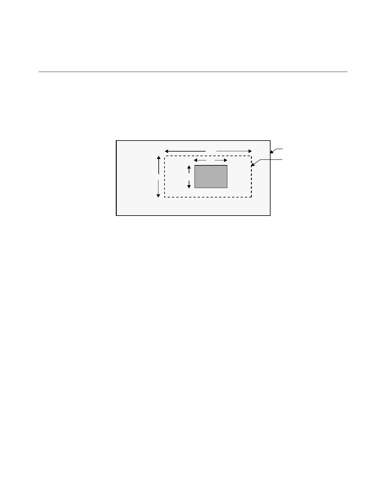
Accessing Image Data
45
The x, y, nx, ny, data, and config parameters have the same meanings as they have in
getTile() and setTile(). The remaining parameters specify the origin of the data buffer
(dx,dy) relative to the image and the size of the buffer (dnx and dny), as shown in
Figure 2-10. (This figure assumes that the image’s orientation defines the origin as the
lower left corner.)
Figure 2-10 Parameters for getSubTile() and setSubTile()
With either function, if the data buffer is the same size as the source tile, then x=dx, y=dy,
nx=dnx, and ny=dny.
getPixel() and setPixel()
If you would rather read or write pixels than tiles, use getPixel() or setPixel():
ilStatus getPixel(int x, int y, ilPixel& pix);
ilStatus setPixel(int x, int y, ilPixel& pix);
These functions read or write the pixel at location (x,y) in the calling image. When a pixel
of data is read, it is placed in the location referenced by pix. The pix argument for
setPixel() references the data that is written into the calling image at (x,y).
fillTile()
As a special case of writing a tile of data, you can set an arbitrary rectangular area of an
image to a constant value with fillTile():
ilStatus fillTile(int x, int y, int nx, int ny,
const void* data, const ilConfig* config=NULL,
const iflTile3Dint* fillMask=NULL);
nx
ny
(x,y)
dnx
dny
(dx,dy)
Image
Data Buffer
(0,0)
Tile

46
Chapter 2: The ImageVision Library Foundation
The rectangular area to be filled is specified by its origin (x,y) and size (nx and ny),
measured in pixels. The data argument specifies the value used to fill the tile; it is
typically an iflPixel object (for C++ programmers). For example, to fill a tile with white,
use an iflPixel with these values: 255, 255, 255. The optional config argument describes the
configuration of data. If it is omitted, data is assumed to have the same configuration as
the image being filled.
The last argument, fillMask, allows you to define a mask that prevents a portion of the tile
from being filled. (See “Auxiliary Classes” on page 358 for a detailed description of the
iflTile class.) If it is not NULL, only the portion outside of the fillMask is filled.
Three-dimensional Functions
The three-dimensional data access functions are the same as their two-dimensional
counterparts, except that they take extra arguments as necessary to handle an image’sz
dimension. For example, getTile3D(),setTile3D(), and copyTile3D() take arguments to
specify the origin and size in the z dimension:
ilStatus getTile3D(int x, int y, int z, int nx, int ny,
int nz, void* data, const ilConfig* config=NULL);
ilStatus setTile3D(int x, int y, int z, int nx, int ny,
int nz, void* data, const ilConfig* config=NULL);
ilStatus copyTile3D(int x, int y, int z,
int nx, int ny, int nz,
ilImage* image, int ox, int oy, int oz,
int* chanList=NULL);
The copyTileCfg() function works similarly to the copyTile3D() function, except that it
allows the channels of the copied data to be offset as well as reordered when it is copied:
virtual ilStatus copyTileCfg(int x, int y, int z,
int nx, int ny, int nz,
ilImage* image, int ox, int oy, int oz,
const ilConfig* config=NULL);
Note: This function takes an ilConfig* argument rather than an int*. Only fields in the
ilConfig that refer to the number of channels, channel list, and channel offset are used
during the copy; the other fields are ignored.
The getSubTile3D() and setSubTile3D() functions require several additional arguments
to specify the origin and size of the z dimension in both the source and the destination:

Accessing Image Data
47
ilStatus getSubTile3D(int x, int y, int z,
int nx, int ny, int nz,
void* data, int dx, int dy, int dz,
int dnx, int dny, int dnz,
const ilConfig* config=NULL) = 0;
ilStatus setSubTile3D(int x, int y, int z,
int nx, int ny, int nz,
void* data, int dx, int dy, int dz,
int dnx, int dny, int dnz,
const ilConfig* config=NULL) = 0;
The fillTile3D() function takes arguments that are similar to the two-dimensional
versions:
virtual ilStatus fillTile3D(int x, int y, int z,
int nx, int ny, int nz,
void* data, const ilConfig* config=NULL,
const iflTile* fillMask=NULL);
Data Access Support Functions
This section discusses a few functions designed to perform tasks related to accessing
data. getStrides() helps you step through a buffer of image data. clipTile() clips a tile to
the dimensions of the image.
Using getStrides()
In some situations, you might want to step through a buffer of image data pixel by pixel,
rather than simply reading or writing a single tile of data. Or you might want to move
some specific number of pixels in a particular direction. To do this, you need to know
where one pixel’s data ends and the next one’s begins. This information, called the stride,
depends on the image’s data type, pixel ordering, and the size of the data buffer.
getStrides() returns data strides by reference:
void getStrides(int& xs, int& ys, int& zs, int& cs,
int nx=0, int ny=0, int nz=0, int nc=0,
iflOrder ord=iflOrder(0));
You specify the size of the data buffer, nx, ny and nz, and the pixel ordering, ord. The
default value, iflOrder(0), means that the calling image’s ordering should be used. The
remaining values are returned by reference:

48
Chapter 2: The ImageVision Library Foundation
•xs, the x stride, steps to the next pixel in the same row.
•ys, the y stride, steps to the next pixel in the same column.
•zs, the z stride, steps to the next pixel along the z axis at the same xy location.
•cs, the channel stride, steps to the next channel of the same pixel.
•nc is the number of channels in the data.
clipTile()
Another useful function, clipTile(), clips a specified tile to an image’s boundaries:
ilStatus clipTile(int& x, int& y, int& z,
int& nx, int& ny, int& nz, int includeBorder=FALSE);
The arguments specify, by reference, the origin (x, y, z) and size (nx, ny, nz) of the tile. The
includeBorder argument specifies whether the page borders of the image should be used
to determine clipping. If includeBorder is TRUE, the clipped tile includes a border at the
edge of the image whose size is determined by the IL (or by setPageBorder() if you
choose to use this function). If includeBorder is FALSE (which it is by default), the tile is
clipped to the actual image edge, not including any borders. If any part of the tile lies
outside the image’s boundaries, the corresponding argument is adjusted as necessary to
clip the tile. You can then use the parameters in a call to getTile() or setTile(), for
example. If the tile is clipped, clipTile() returns ilDATACLIPPED; otherwise, it returns
ilOKAY.
Orientation Support
Several functions are defined to help you translate image data between different
orientations:
iflOrientation mapFlipTrans(iflOrientation fromSpace,
iflFlip& flip, int& transXY,
iflOrientation workSpace=iflOrientation(0));
void mapTile(iflOrientation fromSpace, iflTile& tile,
iflFlip& flip, int& transXY,
iflOrientation workSpace=iflOrientation(0));
void mapTile(iflOrientation fromSpace, iflTile& tile,
iflOrientation workSpace=iflOrientation(0));
void mapXY();

Accessing Image Data
49
void mapXY(iflOrientation fromSpace, int& x, int& y,
iflOrientation workSpace=iflOrientation(0));
void mapXY(iflOrientation fromSpace, float& x, float& y,
iflOrientation workSpace=iflOrientation(0));
void mapXYSign(iflOrientation fromSpace, float& x, float& y,
iflOrientation workSpace=iflOrientation(0));
iflOrientation mapSpace(int flipX, int flipY,
int transXY=FALSE);
void getSize(iflSize &sz, iflOrientation workSpace);
int isMirrorOrientation(iflOrientation otherSpace,
iflOrientation workSpace=iflOrientation(0));
The mapFlipTrans() function determines the flips and/or transpositions necessary to
map coordinates from the fromSpace orientation to workSpace (and returns them by
reference). The mapTile() and mapXY() functions map the specified tile or (x,y) point
from fromSpace to workSpace. The mapXYSign() function reverses the sign of the (x,y)
values if workSpace is flipped with respect to fromSpace; it also swaps the values (that is,
exchanges x for y and vice versa) if the orientations are transposed. The mapSpace()
function returns the orientation that results from performing the specified flips,
transpositions, or both. The other two functions return information related to an image’s
orientation. The getSize() function maps the image’s size to the workSpace orientation
and returns it by reference. The isMirrorOrientation() function returns whether
otherSpace is a mirror image of workSpace.
For more information about these functions, see the ilImage reference page.
Geometric Mapping Support
Four functions are defined in ilImage to support image processing operators that
perform geometric transformations:
void mapToSource(iflXYfloat& src, const iflXYfloat& self);
void mapFromSource(iflXYfloat& self, const iflXYfloat& src);
virtual void evalXY(iflXYfloat& xy, const iflXYfloat& uv);
virtual void evalUV(iflXYfloat& uv, const iflXYfloat& xy);
mapToSource() transforms the coordinates in self into the source image’s orientation and
places them in src.mapFromSource() transforms the coordinates in src into the calling
image’s orientation and places them in self. evalXY() maps from the calling image’s

50
Chapter 2: The ImageVision Library Foundation
orientation to the immediate input image’s orientation. evalUV() maps from the
immediate input image’s orientation to the calling image’s orientation.
The IL Execution Model
This section describes the IL execution model and explains, in general, how it works in
an IL program. Features of the IL execution model are:
•on-demand processing of image data using chains of IL operators
•multi-threading to allow some portions of an IL program to execute in parallel
•the use of hardware acceleration whenever possible to improve the performance of
operators in an IL chain
The IL incorporates these features into your program automatically. You need to
understand them, however, to tune your program for optimum performance.
On-demand Processing
In the IL’s execution model, image data is processed only on demand. This technique
minimizes both the need to store intermediate results and the frequency of disk input
and output operations so that overall program performance is optimized. IL programs
that apply multiple successive image processing operators or that deal with large images
especially benefit from this execution model.
Note: An operator is a class derived from ilOpImg that applies its image processing
algorithm to the data encapsulated in an ilImage object. See Chapter 4, “Operating on an
Image,” for more information.
An IL program implements the demand-driven execution model in two stages:
1. It creates a chain of image processing operators by creating the desired operator
classes.
2. It pulls data through the chain as it is needed. The impetus for pulling data through
the processor chain is the need for the image data at the end of the chain, either for
display or storage on disk. The data is pulled by processing one to several pages at a
time.
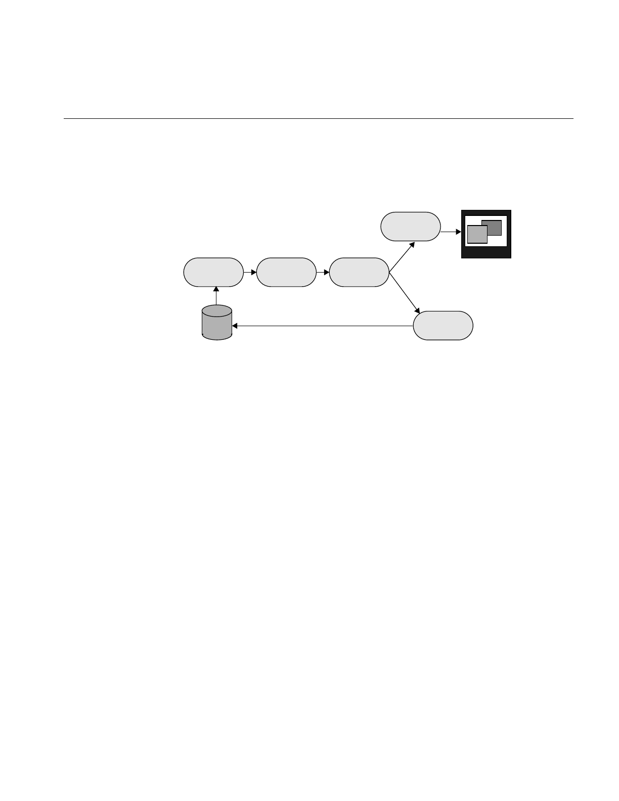
The IL Execution Model
51
In Example 1-1, a relatively simple image chain is constructed. Figure 2-11 shows this
chain with arrows indicating the path that image data follows as it is read from disk,
processed (sharpened and rotated), displayed, and written to disk.
Figure 2-11 Image Chain for the Sample Program
An image processing library that uses the conventional execution model shuffles data in
and out of memory at each stage of the chain. Such a program:
1. Reads the initial image data from disk into a buffer.
2. Sharpens it.
3. Writes the sharpened data into a different buffer.
4. Rotates the sharpened data.
5. Writes the final, processed data into another buffer.
6. Writes the final data into the framebuffer and back to disk.
If the image is too large to be cached in memory, a conventional library will write at least
some of the processed data to disk for each intermediate stage. This data then needs to
be read back in from disk for each successive stage.
In contrast, the IL pulls one or several pages of image data at a time all the way through
the chain. After a page is completely processed—in this example, read from disk,
sharpened, rotated, displayed, and written to a file on disk—the next page is pulled
through the chain. When multi-threading is enabled, several pages can be in process
through the chain at any one time. This execution model eliminates the need to save
intermediate processing results for all images, regardless of their size. The IL’s model
also minimizes startup time for IL programs, particularly those that allow the user to
ilSharpenImgilFileImg
ilDisplay
ilTIFFImg
ilRotZoomImg
disk
monitor
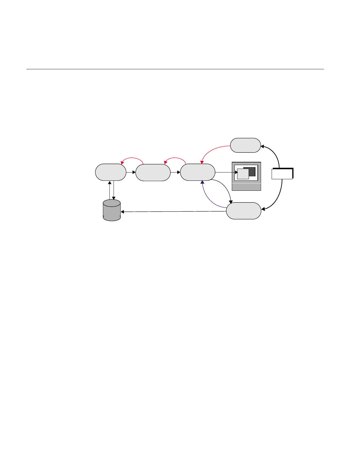
52
Chapter 2: The ImageVision Library Foundation
roam around a large image. The data for the entire image is not processed before startup;
it is processed only as needed, which, in this case, is as the user roams.
The arrows in Figure 2-12 show how data is pulled through the image chain in
Example 1-1.
Figure 2-12 Image Chain Showing Demand-driven Execution Model
In this example, the redraw() and copyTile() function calls issued by the program
instigate the processing of image data. They cause successive tiles of image data to be
pulled through the chain and sent to the display or back to the disk. As each tile is
written, another tile is requested from the previous stage of the chain with a getTile(),
copyTile(), or ilMemCacheImg::executeRequest() calls. If the tile requested does not
already reside in the cache, the page containing that tile is pulled through the chain—
read from disk, sharpened, and rotated. The ilDisplay class manages the transfer of data
from the end of the chain to the framebuffer.
In Example 1-1 in Chapter 1, “Writing an ImageVision Library Program,” the instigating
functions—ilDisplay’sredraw() and ilTIFFImg’scopyTile()—are actually called in the
program. The other function calls are generated automatically as the program executes.
Thus, only data that is actually needed is pulled through the chain.
Example 1-1 displays and writes to disk the entire processed image one tile at a time.
Other image processing programs might not even process an entire image. For example,
suppose that instead of simply displaying the entire final image, a program allows the
ilSharpenImg
ilFileImg
ilDisplay
ilFileImg
redraw()
setPage()
ilRotZoomImg
disk
copyTile()
getTile()
getTile()
copyTile()
ilMemCacheImg::executeRequest()
getTile()
tile tile tile
monitor
Program
tile
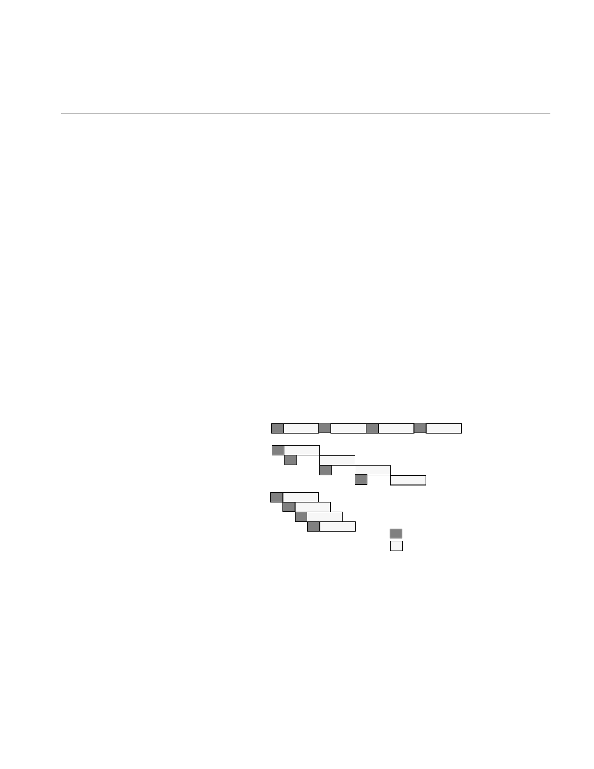
The IL Execution Model
53
user to roam around the image, viewing only a fraction of it at a time. This kind of user
interface is typically provided with programs that deal with huge images. Since IL
programs process data only as it is needed, only those portions of the image that the user
demands to see are processed. It is often the case that the user will never view some
portions of a large image; those portions are not read from disk or processed. Thus, the
IL helps minimize your program’s overall processing requirements.
Multi-threading
The multi-threading part of the IL’s execution model optimizes overall program
performance by allowing portions of an IL program to execute in parallel. For example,
when a tile covering several pages is copied from one operator to the next in a chain and
the tiles are not resident in cache, they must be fetched from disk. The IL implements the
parallel fetching of pages by queueing a request for each page and creating a process
thread to service each request.
Figure 2-13 shows how long it takes to read in and perform computations on four pages
in a non-multi-threaded application, a multi-threaded application running on a
single-processor machine, and a multi-threaded application running on a
multiple-processor machine. As you can see, the multi-threaded applications complete
this transaction more quickly than the non-multi-threaded application.
Figure 2-13 Performance Comparison of Non-threaded, Single-processor, and Multi-processor
Applications
IL supports parallel execution on single- and multiple-CPU machines by creating process
threads that execute portions of an IL program simultaneously. This multi-threading
Non-threaded
Single-processor
Multi-processor
th1
th2
th1
th2
th1
th2
th3
th4 Input/Output performed
Computations performed
Thread = th

54
Chapter 2: The ImageVision Library Foundation
facility is implemented transparently and automatically: there are no special function
calls to make or header files to include. When you derive new classes from the existing
classes in the library, however, you must ensure that the code you produce is reentrant,
that is, able to be called from several process threads running concurrently. Chapter 7,
“Optimizing Your Application,” explains how to do this.
When debugging your application or linking with other libraries that perform
multi-threading, you may want to turn off IL’s multi-threading facility. The preferred
way to do this is to set the environment variables IL_COMPUTE_THREADS and
IL_SPARE_THREADS to zero by using the convenience function ilMPSetMaxProcs(), as
follows.
ilMPSetMaxProcs(0,0);
This global function does not belong to any class.
How Multi-threading Works
When the IL processes a getTile() or copyTile() call, it determines the pages needed for
the requested tile and dispatches a request for each page. It then maintains these requests
in a queue and creates process threads to service the queue. Figure 2-14 illustrates the
concept of multi-threading as well as the on-demand processing described in the
preceding section.
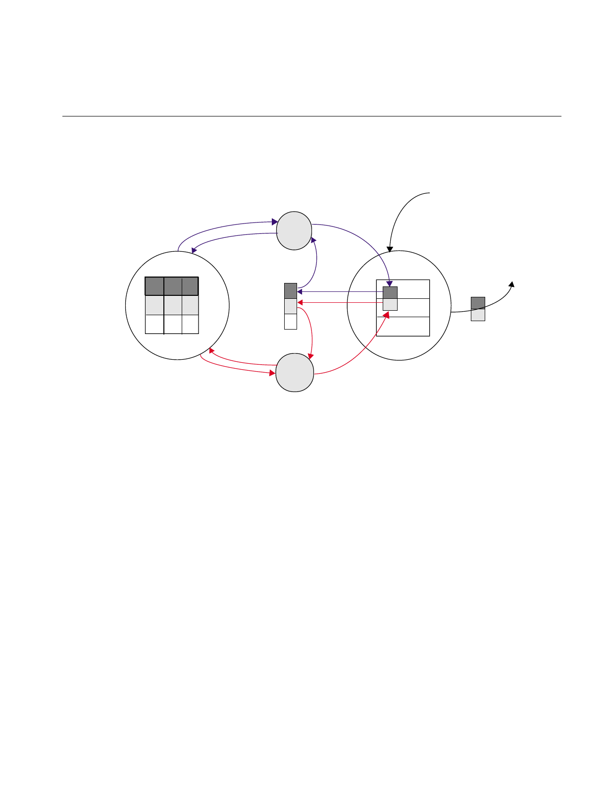
The IL Execution Model
55
Figure 2-14 Operators, Requests for Pages, and Threads
Using Graphics Hardware for Acceleration
The hardware acceleration facility built into the IL allows your application to
automatically take advantage of specialized graphics hardware whenever possible in
order to make certain IL operations more efficient. IL does this by performing one or
more operations at the end of a chain in the graphics hardware instead of the CPU. On
some architectures, it does this by reserving part of the framebuffer as a pixel buffer for
IL. Computations are then performed on the data stored in the framebuffer and
displayed more quickly than if the data were being operated on in the CPU and brought
in from main memory. If the IL needs a tile that is not in the reserved part of the
framebuffer, the tile is brought into the framebuffer from main memory. This model is
implemented transparently and automatically; there are no header files to include or
function calls to make.
ilOp2
ilOp1
getTile()
getTile()
thread1
thread2
getTile()
request
queue
Request for a tile that spans two
pages is pulled through the image
chain
Retrieved tile is sent
to the buffer
processed
tile processed
page
processed
page
processed
tile
page
requests

56
Chapter 2: The ImageVision Library Foundation
Disabling Hardware Acceleration
Sometimes you need to disable the hardware acceleration facility, for example:
•when you are debugging your program. You cannot debug with this facility
enabled if the operator you need to test is a CPU operation that is accelerated in the
hardware.
•when you need more accurate results. Computing some operations in the CPU (for
example, those that require a resampling method) gives more accurate results at the
expense of speed.
You can enable and disable the hardware acceleration facility:
•globally for all features of the IL
•for specific objects of an operator class
•for all objects of a specified class
“Using Hardware Acceleration” gives detailed information about how to enable and
disable hardware acceleration.
Page Borders
Some image processing operations, for example, those that perform image warps,
require the data in the pages of the cache to overlap a bit. A set of page borders determines
how much the pages in the cache can overlap for these operations. The page borders are
set automatically for you by IL and should rarely be changed. You can use the
setPageBorder() and getPageBorder() functions, however, to query and set page
borders.
Working with Image Chains
Your IL programs always contain image chains. An image chain is a string of operators
that define the operations you want to perform on your images and the order in which
these operations are performed. You can manipulate these chains after they are created.
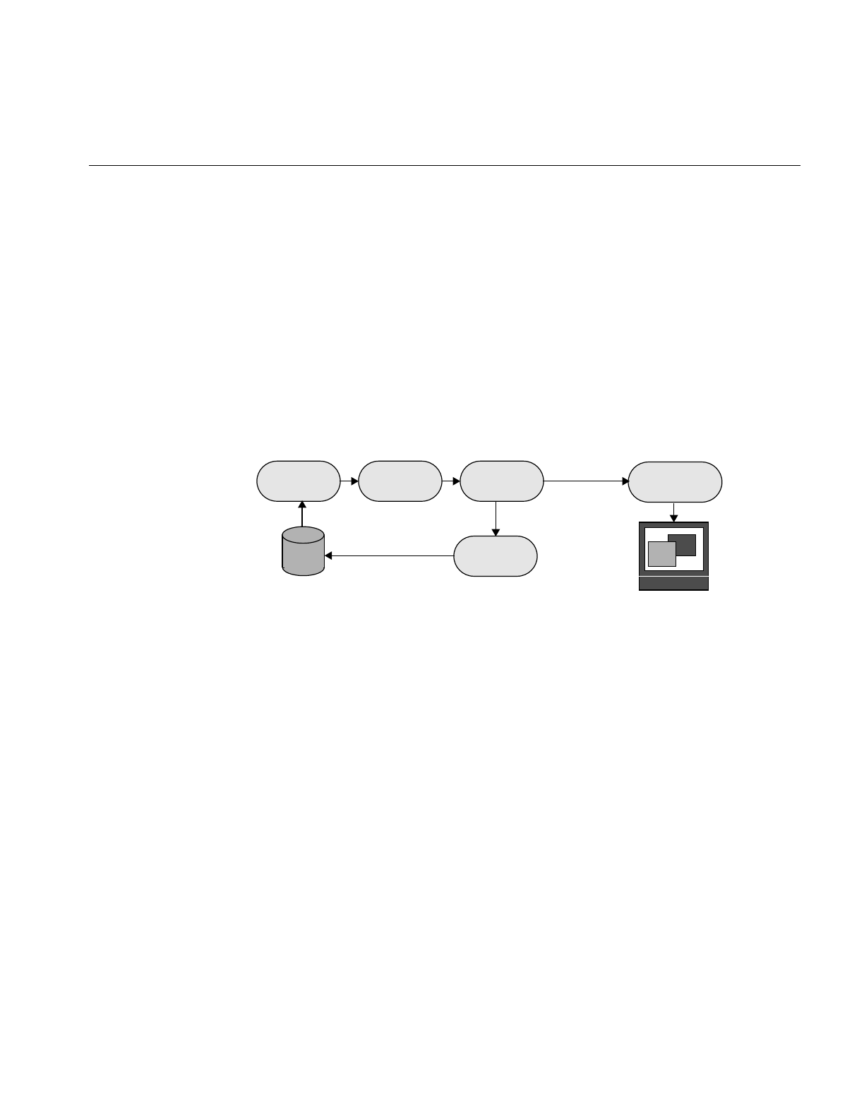
Working with Image Chains
57
Dynamically Reconfiguring a Chain
Some IL programs need to construct new image chains dynamically as the program
executes. For example, imagine a program with a graphical user interface that allows its
user to specify input images and select operations to be performed on them. Once
processing has been performed, the user can choose to operate further or to start again
with new images and operators. Such a program is most easily implemented by taking
advantage of the IL’s facility for reconfiguring an image chain.
Each image in a chain maintains two lists, one of the images directly preceding it in the
chain (its inputs or parents) and one of the images succeeding it in the chain (its children).
In the chain shown in Figure 2-15, for example, the ilRotZoomImg object has one parent,
the ilSharpenImg object, and two children, the ilTIFFImg and ilDisplay objects.
Figure 2-15 An Image Chain
The first item on a list is at index 0.
Replacing a Chained Operator
Let’s say you want to modify Example 1-1 so that it can dynamically add a threshold
operator in place of the ilSharpenImg operator. The ilThreshImg operator examines each
pixel in an image and potentially sets each pixel to a new value, depending on whether
its value is higher or lower than a specified threshold value. If a pixel is higher than or
equal to the threshold, it is set to the image’s maximum pixel value; if the pixel is lower,
it is set to the minimum value.
ilSharpenImgilFileImg ilDisplay
ilRotZoomImg
disk
monitor
ilTIFFImg

58
Chapter 2: The ImageVision Library Foundation
Here is what the code might look like to replace the ilSharpenImg operator with an
ilThreshImg operator (this code can be inserted just before step 3 in Example 1-1 in
Chapter 1, “Writing an ImageVision Library Program”):
// set the threshold value to 127.5
float threshValue = 127.5;
iflPixel threshPixel(iflFloat, 1, &threshValue);
// create the ilThreshImg operator
ilThreshImg myThresher(inImg, threshPixel);
// replace ilSharpenImg with ilThreshImg
rotatedImg.setInput(&myThresher);
This example is simplified, but it demonstrates the use of setInput() to reconfigure a
chain. A more realistic program would let the user specify the threshold value to be used
and also might let the user specify any of a number of different operators to be replaced
or added to the chain.
In this code fragment, the threshold value is explicitly set to 127.5. An iflPixel object is
created with this value. Next, the ilThreshImg operator is created and given the input
image inImg (which is the ilFileImg created in the sample program to read an image file
from disk) and the iflPixel.
The setInput() function removes the ilSharpenImg operator from the chain by replacing
it with the new ilThreshImg operator. This function, which is declared in ilImage, takes
a pointer to the new, already created input ilImage as its first argument. In this example,
the ilThreshImg operator is now the input image for the ilRotZoomImg object,
rotatedImg. The old input, which in Example 1-1 was an ilSharpenImg object, is not
deleted by IL, so you might want to delete it if it is not needed anymore. The attributes
of the new input image are propagated down the operator chain as described in
“Propagating Image Attributes” on page 59.
A second, optional argument for setInput() is of type int. It specifies the index position
where the input should be added. By default, this argument is 0, indicating the first
position on the list. Before the setInput() call, the ilSharpenImg operator occupies
position 0 on ilRotZoomImg’s list of inputs. Afterward, the ilThreshImg operator is at
position 0, having replaced the ilSharpenImg operator.
Querying Chained Images
Although you probably will not frequently need to query a chained image about the
operators it is chained to, the ilImage base class defines functions for you to do so. The

Working with Image Chains
59
function getNumInputs() returns an int, indicating the number of inputs or links
backward; getNumChildren() (inherited from ilLink) returns the number of children
which are forward links.
You can also obtain a pointer to the preceding or succeeding linked images using the
following functions:
ilImage* myInput;
ilImage* myChild;
myInput = theImg.getInput(0);
myChild = theImg.getChild(0);
As its name implies, getInput() returns a pointer to the ilImage preceding it in the chain;
getChild() (inherited from ilLink) returns a pointer to the ilImage succeeding it. Since
there can be multiple inputs and children, both of these functions allow you to specify
the indexed position of the image you wish to retrieve. By default, this argument is 0,
indicating the first position on the indexed list.
Adding and Removing Inputs
Some operator images can have a variable number of inputs. For such operators, you
may need to dynamically change the number of inputs as a chain is reconfigured. The
following two functions that are provided for this purpose:
ilStatus addInput(ilImage* img);
ilStatus removeInput(int index = 0);
The addInput() function adds the ilImage supplied as an argument to the end of its
current list of inputs. As its name suggests, removeInput() removes the ilImage located
at the specified index from its list of inputs. An ilImage object removed from the chain is
not deleted, so you might want to delete it if it will not be used anymore.
The setNumInputs() function sets the maximum number of inputs to the int passed in
as its argument. Since this function is declared protected, you can use it only when you
are deriving a class from ilImage.
Propagating Image Attributes
One important property of image chains is that they propagate attribute values to
succeeding stages of the chain. In other words, each stage of the chain receives some or
all of the attributes of the preceding stage. The attributes that are propagated—image

60
Chapter 2: The ImageVision Library Foundation
size, data type, order, orientation, color model, lookup table, page size, minimum and
maximum pixel values, and the fill value—are defined in ilImage and discussed in
“Image Attributes” on page 20.
Changing Image Attributes
Image attribute values can change, either from being set explicitly or as a result of
performing an operation. You can override a propagated value by explicitly setting it (if
the operator allows you to do so), in which case the IL discards any data residing in the
cache.
Operators can restrict the values for certain attributes. A supported value will not be
overridden by an unsupported propagated one. In addition, chains can be constructed
so that one link has more than one preceding link (for example, ilBlendImg blends two
images). In these cases, the most appropriate value is propagated; usually, this is the
largest (for the size attribute, for example) or the most general value.
Typically, if you have explicitly set an attribute value using one of the appropriate
functions defined in ilImage, for example, setDataType() or setPageSize(), you do not
want it overridden automatically by a propagated value. IL makes this assumption so it
keeps track of any attributes that you have set. These attributes are not allowed to change
through propagation down the chain unless you indicate they should be. To allow an
attribute to change even though you have set it, call clearSet() (inherited from ilLink). In
the following line of code, the call allows the data type to be reset:
myImg.clearSet(ilIPdataType);
The argument to clearSet() can be any logical combination of the enumerated type
ilImgParam, which is defined in the header file il/ilImage.h and discussed in more detail
in Chapter 6, “Extending ImageVision Library.” For more information about how the
propagation mechanism is implemented, see “Deriving From ilImage” on page 202.
Automatic Color Conversion of Inputs
If the input(s) to an operator does not match its color model (either as inherited from
multiple inputs or as set by the user), an ilColorImg object is inserted automatically
between the operator and its input(s). The ilColorImg object converts any mismatched
input to match the operator’s color model.
In some cases, this automatic conversion is not desired, especially for operators such as
ilColorImg and ilFalseColorImg that perform color conversions as part of their

Object Properties
61
operations. These operators can prevent the insertion of an ilColorImg by setting the
member variable allowDiffCM to TRUE, either in their constructor or when they initialize
their state. When allowDiffCM is TRUE, the operator must be prepared to handle inputs
of any color model for proper operation to be guaranteed. The default value is FALSE.
Object Properties
The IL allows you to assign and query property values and associated property names to
objects derived from ilLink. This functionality allows you to tag an object with arbitrary
attributes. A property value can be an integer, a floating point number, or a pointer. The
property name is a character string.
The IL provides three scope levels for property values:
•ilInstanceScope – defines the scope as a specified object
•ilClassScope – defines the scope as an object class
•ilGlobalScope – defines a global scope
IL provides several redundant functions to set and query property values. In each of
these functions, a scope argument specifies the search range for property lookup. This
argument can be any logically OR’ed combination of ilInstanceScope, ilClassScope, and
ilGlobalScope. If ilInstanceScope is specified, the object’s property set is searched. If
ilClassScope is specified, the object’s class property set is searched. Finally, if
ilGlobalScope is specified, the global property set is searched. If more than one of the
search scopes is specified, each of the specified scopes is searched in this order: the object
instance scope, then the object class scope, then the global scope. The default value for
scope is ilInstanceScope.
The functions provided for a property value refer to a property associated with a
character string name or, alternatively, with an ilName pointer that is used as a search
key. It is more efficient to look up a property using an ilName pointer than a string
because hashing is avoided. See the ilGlobalName reference page to find out how to
obtain an ilName pointer from a string.
The getIntProp() functions return the integer property value associated with either the
string, s, or an ilName pointer. These functions return 0 if no such property has been
defined.
int getIntProp(Char *s, ilScope scope_ilInstanceScope);
int getIntProp(ilName* n, ilScope scope_ilInstanceScope);

62
Chapter 2: The ImageVision Library Foundation
The getFloatProp() functions return the float property value associated with the string,
s, or an ilName pointer. These functions return 0 if no such property has been defined.
float getFloatProp(char* s, ilScope scope=ilInstanceScope);
float getFloatProp(ilName* n, ilScope scope=ilInstanceScope);
The getPtrProp() functions return the pointer property value associated with the string,
s, or the ilName. These functions return NULL if no such property has been defined.
void* getPtrProp(char* s, ilScope scope=ilInstanceScope);
void* getPtrProp(ilName* n, ilScope scope=ilInstanceScope);
The getProp() functions return the property associated with the string, s, or an ilName
pointer. These functions return NULL if no such property has been defined.
ilProperty* getProp(char* s, ilScope scope=ilInstanceScope);
ilProperty* getProp(ilName* n,
ilScope scope=ilInstanceScope);
You can use one of the following setProp() functions to associate a property value with
the string, s, or an ilName pointer. These functions return ilOKAY if scope is one of the
following: ilInstanceScope, ilClassScope, or ilGlobalScope. Otherwise, it returns
ilUNSUPPORTED. The object is not marked altered as a result of setProp().
ilStatus setProp(char* s, int i,
ilScope scope=ilInstanceScope);
ilStatus setProp(ilName* n, int i,
ilScope scope=ilInstanceScope);
ilStatus setProp(char* s, float f,
ilScope scope=ilInstanceScope);
ilStatus setProp(ilName* n, float f,
ilScope scope=ilInstanceScope);
ilStatus setProp(char* s, void* p,
ilScope scope=ilInstanceScope;
ilStatus setProp(ilName* n, void* p,
ilScope scope=ilInstanceScope);
ilStatus setProp(char* s, const ilPropValue& val,
ilScope scope=ilInstanceScope);
ilStatus setProp(ilName* n, const ilPropValue& val,
ilScope scope=ilInstanceScope);
The removeProp() functions remove the property associated with the string, s, or the
ilName pointer n from the specified property set.The object is not marked altered as a
result of removeProp().
ilStatus removeProp(char* s, ilScope scope=ilInstanceScope);

Object Properties
63
ilStatus removeProp(ilName* n,
ilScope scope=ilInstanceScope);
The getClassPropSet() function returns a pointer to the property set associated with the
object’s class.
ilPropSet* getClassPropSet();
The getPropSet() function returns a pointer to the object’s property set.
ilPropSet* getPropSet();


65
Chapter 3
3. Accessing External Image Data
This chapter describes how to use IL to read and write image data. IL uses the Image
Format Library (IFL) to accomplish all image input and output (I/O). IFL provides an
abstraction of low level image I/O that lets users write applications without dealing with
IL or the details of the image file formats that are being used. It is not even necessary to
know what image file format is being used (though IFL does provide facilities for
determining the format of an image and accessing special features which are not part of
IFL’s image I/O abstraction).
IL provides access to images using the ilFileImg class. Its objects can be part of image
chains. This class caches image data in order to reduce the amount of image I/O. IL often
provides more flexible access to image data than that provided by IFL since IFL’s focus
is on a simple I/O abstraction. For example, some image formats do not support paging.
When using IFL to access an image stored in such a format, an application is forced to
read the entire image and then extract the portions of the image of interest. IL can provide
this functionality much more simply using its extensive image access facilities.
The rest of this chapter describes how to use IL to access image data. While reference is
often made to IFL, the focus is on using the ilFileImg class to read and write image data.
To learn more about using IFL directly to access image data, see the IFL(3) manual page.
This chapter contains the following major sections:
•“Supported IFL Image File Formats” on page 66 describes the image file formats
supported by IFL.
•“Using IL to Access an Image” on page 71 tells you how to access data in the file
formats.
•“Importing and Exporting Image Data” on page 78 discusses how to import and
export image data between IL and other libraries or devices.

66
Chapter 3: Accessing External Image Data
Supported IFL Image File Formats
IL provides access to images stored in a variety of formats using IFL. Table 1-1 shows all
of the ifl-supported image file formats and their customary suffixes. The sources to many
of the file format modules supported by IFL are located in /usr/share/src/ifl/.
Any image file format that is accessible using IFL is also accessible using IL.
IFL can be extended to accommodate new image file formats. For more information
about adding a new image file format, see Appendix E, “Implementing Your Own Image
File Format.”
The following sections describe the file formats currently supported by the Image Format
Library, and, by extension, the ImageVision Library.
FIT
The FIT file format is a simple, tiled format developed along with IFL. You might use FIT
as a starting point for defining your own file format.
FIT supports the full flexibility of the IFL model: all data types, orders, and page sizes. It
uses a default page size of 128 x 128. FIT allows you to reserve space to hold user
extensions to the file format. FIT is the only format that supports paging in the channel
dimension. This functionality is useful for multispectral imagery.
GIF
The GIF file format is used to read image files stored in the CompuServe Graphics Image
File (GIF) format. GIF does not support paging. It stores images in
palette-color-compressed using the Lempel-Ziv & Welch algorithm1. GIF images are
limited to using unsigned character data and an upper-left coordinate system. To obtain
more information about GIF specifications, contact CompuServe, Incorporated,
Columbus, Ohio.
1The compression algorithm has become the focus of patent infringement litigation which has inspired
the creation of a new image format to replace GIF. This new format is the Portable Network Graphics
(PNG) image format. It is also supported by IFL.

Supported IFL Image File Formats
67
JFIF (JPEG)
JFIF implements the JPEG file format using the JPEG library, libjpeg, made available by
the Independent JPEG Group. In addition to providing the IFL image I/O abstraction,
the entire JPEG library is provided as is for use by software that has been developed for
use with libjpeg.
Version 6, 2-Aug-95 of the Independent JPEG Group’s compression library, libjpeg, and
its standard headers, jconfig.h,jpeglib.h,jmorecfg.h, and jerror.h, are installed as part of IFL.
ilTCL
The ilTCL file format allows you to save an operator chain in a file using a TCL-based
scripting language. That file can then be treated like any other image file.
Kodak Photo CD Image Pac
The PCD file format supports image files produced by the Kodak Photo CD™ system.
Photo CD establishes a system for storing high-resolution, digital photographic images
on compact discs. The Kodak Photo CD system
•scans photographic film
•processes the scanned images (color correction, color encoding, hierarchical
decomposition, and compression)
•records these images as a series of digitally-coded images on a Kodak Photo CD
disc
In addition to digital images, Kodak Photo CD can produce digital audio data and
playback control data. However, IFL only handles the image data files from a Photo CD
disc.
Photo CD Images
A photographic image on a Kodak Photo CD disc is stored as a hierarchy of images, each
of which represents the original image at a different resolution. This image hierarchy is

68
Chapter 3: Accessing External Image Data
stored in a structure called an Image Pac. You can get a maximum of seven different
resolutions of an image from an image pack. These resolutions are:
An Image Pac file always contains the first four resolutions listed above. The resolutions,
4Base and higher, can be omitted when the Photo CD disc is created. Resolutions Base/64
through Base are stored directly and can be accessed quickly. Resolutions 4Base and
higher, if they are available in the image file, are stored in a compressed form.
You can use the ilFileImg member function, getNumImgs(), to determine the number of
images in your Photo CD file. You can use the setCurrentImg() and getCurrentImg()
functions to select and query the current resolution. If you use setCurrentImg() to select
an image resolution that does not exist in the image pack, the function returns the ilStatus
value iflBADPARAMS but does not set the image’s status. The default image resolution
is Base/4.
The page size of a Photo CD Image is the full x dimension of the image by 16 in the y
dimension (16 rows in Kodak Photo CD jargon).
Note: The supplied Photo CD format is not capable of writing Photo CD image files.
Photo CD Color Model
The color model of a Kodak Photo CD image is YCC. Photo YCC is a
luminance/chrominance data metric that is based on video primaries. It is designed to
allow simple video display without compromising the colors available in photographic
media. You can convert from the YCC color model to another color model using IL. You
cannot, however, use IFL to do the reverse: conversion from another color model to YCC.
name resolution image index
Base/64 (96x64) 0
Base/16 (192x128) 1
Base/4 (384x256) 2
Base (768x512) 3
4Base (1536x1024) 4
16Base (3072x2048) 5
64Base (6144x4096) 6

Supported IFL Image File Formats
69
Kodak Photo CD Overview Pac
Every Kodak Photo CD contains a file in the Kodak Photo CD Overview Pac format. This
format contains a low resolution representation of each image on the Photo CD. The
ilPCDOImg class allows you to retrieve each of the overview images at either Base/16 or
Base/64 resolution (the default is Base/16).
You can use the ilFileImg member function, getNumImgs(), to determine the number of
images in your Photo CD Overview file. You can use the setCurrentImg() and
getCurrentImg() functions to select and query the current resolution. If you use
setCurrentImg() to select an image resolution that does not exist in the overview pack,
the function returns the ilStatus value iflBADPARAMS but does not set the image’s
status.
Note: The Photo CD Overview format supplied with IFL is not capable of writing Photo
CD image files.
PNG
PNG implements the PNG file format using version 0.88 of the Portable Network
Graphics library, libpng, and version 1.0 of the ZIP deflate/inflate compression library,
libzlib. These libraries and their standard headers, png.h,pngconf.h,zlib.h, and zconf.h, are
installed as part of IFL.
PPM/PGM/PBM
PPM, PGM, and PBM implement the PPM, PGM, and PBM file formats using release 7,
December 1993 of the NETPBM libraries, libppm, libpgm, and libpbm. These libraries
and their standard headers, ppm.h,pgm.h, and pbm.h, are installed as part of IFL.
Raw
The iflRaw image file format accesses raw image data stored in a file. The data must be
organized in raster fashion. If the data is in pages, the pages must be a fixed size (with
partial pages at the image edge padded to fill out the fixed size).

70
Chapter 3: Accessing External Image Data
The iflRaw format supports the full flexibility of the IFL model: all data types, color
models, orders, orientations and page sizes are supported. Like all file formats supported
by IFL, you access raw images using the generic object class (or the ilFileImg object for
IL users).
The default extension for image files in the ilRaw format is .raw.
SGI
SGI is the first format defined by Silicon Graphics for storing image data. SGI files are
typically stored in files suffixed by .bw,.rgb, .rgba,.sgi, or .screen. SGI files support full
color, color palette, and monochrome images of either one or two bytes per color
component. Image data can be stored in either raw form or run-length encoding (RLE)
compression. You can create SGI files with RLE compression but you cannot later rewrite
a portion of a compressed SGI file.
Note: If an SGI-formatted image is RGB Palette, its corresponding color map must be
stored in a separate (also SGI-formatted) file with the name imgName.map, where
imgName is the name of the SGI image.
Page width for SGI files is the width of the image. Page height is a value in the range 16
through 32 that evenly divides the overall height of the image. The SGI format makes the
image order interleaved. SGI supports only unsigned data and a lower-left coordinate
space.
TIFF
The TIFF file format, created by Aldus Corporation, is an extended version of the Tag
Image File Format, using version 3.4beta24 of Sam Leffler’s TIFF library, libtiff. This
library implements version 6.0 of the TIFF specification. The library and its standard
header files, tiff.h and tiffio.h, are installed as part of IFL
The purpose of TIFF is to describe and store raster image data. TIFF can describe bilevel,
grayscale, palette-color, and full-color image data in several color spaces. TIFF includes
a number of compression schemes that allow you to choose the best space or time
trade-offs for your applications. TIFF can also store multiple images per file. IFL uses the
following extensions to TIFF 6.0: Tilewidth, Tilelength, and SampleFormat. These tags
provide necessary support for the image data types and tiles as defined by the IFL.

Using IL to Access an Image
71
The Introduction of this Programming Guide tells you how to obtain more information
about the TIFF 6.0 specification. Refer to ifl/iflTIFF.h to learn more about TIFF tags and the
TIFF specification.
YUV
The YUV file format is the standard 8-bit 4:2:2 (YUV) format used by the Sirius board and
almost all digital disk recorders ( Abekas, Accom etc ). There is extensive documentation
at the top of the source file for the tags.
Alias
The Alias file format supports both variations of the format: 8-bit RGB and 8-bit matte.
SOFTIMAGE
The SOFTIMAGE file format supports reading all types of image files and writes only
mixed RLE compressed. There is no current support for depth buffer files or rendered
subregions.
Note: The Wavefront file format is not currently supported.
Using IL to Access an Image
IL allows you to read and write image data in any of the file formats that support the
desired mode of access. (Some image file formats do not support writing.) IL provides
access to image files using the ilFileImg class. Existing image files can be read and new
ones created simply by constructing an ilFileImg object.
Opening an Existing File
The following example opens an existing file for reading:
ilFileImg myFile("anExistingFileName", O_RDONLY);

72
Chapter 3: Accessing External Image Data
The first argument to the constructor is the name of the image file to be opened. The
second argument is the file access mode. The access mode can be either:
•O_RDONLY to indicate that the file is to be opened only for reading
•O_RDWR if the file can be read from and written to. Remember that not all image
file formats allow writing. For example, the IFL cannot write images in the Kodak
Photo CD format.
The ilFileImg constructor opens the named file. If the named file does not exist, you do
not have read permission, or if it is in an unsupported format, the status of the
constructed ilFileImg object is set to a value other than ilOKAY.
The filename passed to the ilFileImg constructor is subject to a standard parsing before
being used as the name of a file to open. The syntax for filenames is as follows:
filename[#format-name][:image-index][%format-specific]
The filename is the name of the file to open. The format-name, if supplied, specifies the
specific image file format to use to access the image file. The format specification is most
frequently used when creating a file and the format cannot be discerned from the filename
using a standard filename extension for the format. The image-index, if supplied, specifies
the index of an image within a multi-image file to access. Image indices start at 0 but not
all formats support storing multiple images in a single file. The format-specificstring is
passed unchanged to the IFL image file module for format-specific interpretation. This
string is often used to encode arguments to be used when accessing the image file. For
example, the Raw image format uses this string to specify the parameters, such as the
dimension and color model of a raw image. IFL provides a utility routine to parse this
string as a series of position- and name-qualified values. It is up to the individual format,
however, to interpret this string.
After you open an image file, you can read the data, as shown in Example 3-1.
Example 3-1 Opening an Image File and Reading Data
// open the file
ilFileImg* someFile = new ilFileImg("someFileName", O_RDONLY);
// check for errors
if (someFile == NULL || someFile->getStatus() != ilOKAY) {
printf("file %s could not be opened", fname);
exit(1);
}
// obtain image attributes

Using IL to Access an Image
73
iflDataType theDataType = someFile->getDataType();
int xsize = someFile->getXsize();
int csize = someFile->getNumChans();
// allocate buffer
char* buf = new char[iflDataSize(theDataType, xsize*csize)];
// read data into buffer
someFile->getTile(0, 0, xsize, 1, buf);
In this example:
1. A file is opened for reading and a corresponding ilFileImg object is created. If the
file cannot be opened, the program exits.
2. The ilFileImg is queried about some of its attributes to determine what size buffer to
allocate for holding one row of the image’s data.
3. The buffer is allocated. The iflDataSize() function returns the number of bytes
needed for the data type indicated by its first argument, multiplied by the optional
second argument. This function is declared in the header file il/iflDataSize.h and
described in “Computing the Size of Data Types” on page 363.
4. The getTile() function reads the first row of the image’s data into the buffer.
Creating an Image File
To create a new image file, you need to specify the characteristics of the data, such as its
data type, and indicate what file format will be used. The ilFileImg constructor creates a
new image file, as follows:
iflFileConfig cfg(iflSize(xsize, ysize));
ilFileImg newFile(“newFileName”, NULL, &cfg);
This constructor creates an image file with the requested size; all of the other attributes
use the default values. The first argument to the ilFileImg constructor specifies the name
of the file to create. The second argument specifies a pointer to an ilImage to use for
default image attributes, In this example, NULL is used which means the file format’s
own preferred defaults are used. The third argument specifies a pointer to an
iflFileConfig argument which is used to specify various image file attributes: the x and y
size of the image in this example.
Here is a more extensive use of the ilFileImg constructor where many more image
parameters are specified. (All of these attributes are discussed in detail in “Image

74
Chapter 3: Accessing External Image Data
Attributes” on page 20, along with the constants that specify particular values for these
attributes.)
iflFileConfig cfg(iflSize(xsize, ysize, zsize, csize), datatype,
dimensionorder, colormodel, orientation, compression,
iflSize(xpsize, ypsize, zpsize, cpsize));
ilFileImg newFile(“newFileName”, srcImage, &cfg, format);
It is rare that you would specify all of these parameters. In fact, it is likely that such a
fully-specified configuration would be in error, for example, the color model and channel
size would have to agree with one another. Normally, only a few attributes are specified;
the remainder would take default values:
iflFileConfig cfg(iflSize(xsize, ysize), datatype,
iflOrder(0), colormodel, iflOrientation(0), iflCompression(0),
iflSize(xpsize, ypsize));
ilFileImg newFile(“newFileName”, NULL, &cfg);
In this example, the dimension order (iflInterleaved, iflSequential, or iflSeparate), the
orientation, for example, iflLowerLeftOrigin, and the compression are allowed to default
to the format’s preferred values: the z size is set implicitly at 1 and the channel size
matches that of the specified color model. The only attributes specified for the image are
its size, its data type, for example, iflUChar, iflFloat, its color model, for example, iflRGB,
iflRGBPalette, and its page size.
The page size argument defines the x,y,z, and c (channel) dimensions of the pages that
the image is broken into as it is stored on disk. The x,y, and z dimensions are specified in
pixels. Paging in the c dimension is specified in channels and is useful for multi-spectral
images with a large number of channels. If no page size is supplied, the default page size
for that particular format and image size is used.
The attributes specified when creating an image file must match those supported by the
file format being used, for example, TIFF files support any data type except iflDouble,
SGI files support only iflUChar and iflUShort, and FIT files can handle any data type. See
the reference pages in for the various image formats supported by IFL for more
information about what they support.
Once you create a file, you can write data to it. The example shown below assumes the
image file, theImg, of size size was previously created. Its data is written to the file,
outFile.tif, using copyTile().
ilFileImg tmpFile(“outFile.tif”, theImg);
tmpFile.copyTile(0, 0, size.x, size.y, theImg, 0, 0);

Using IL to Access an Image
75
Setting a File’s Compression
Often, images stored on disk are compressed to minimize their size. Such images need to
be decompressed before you can read them. There are many different compression
algorithms and each file format determines which algorithms it supports. From a
programmer’s point of view, as data is read or written in an IL program, its compression
or decompression is handled transparently.
The compression attribute indicates which compression algorithm, if any, is used to
compress the data before it is stored on disk. You should not compress files that will be
interactively modified. Modifying portions of a compressed, existing file is dangerous
because the amount of data written must be the same as what was originally in the file.
In general, the size of a file image, once created, is fixed.
To set a file’s compression algorithm, you must specify the compression algorithm when
the file is created. This can be done either by specifying the compression algorithm
explicitly in the iflFileConfig argument that is passed to the ilFileImg constructor or by
inheriting the compression algorithm from another image used for the source image
attributes. Since the set of compression algorithms supported by formats is highly
variable, one of the easiest ways to specify that you want the image compressed is to use
iflCompression(0) which specifies the format’spreferred compression.
The compression specification used in an iflFileConfig is of type iflCompression.
Table 3-1 lists the iflCompression constants currently defined in the header file
ifl/iflTypes.h and their corresponding compression algorithms.
Table 3-1 Compression Algorithms Supported for ilTIFFImg Files
iflCompression Constant Compression Algorithm
iflCompression(0) use format’s preferred compression
iflNoCompression no compression
iflCCITTFAX3 CCITT Group 3 fax encoding
iflCCITTFAX4 CCITT Group 4 fax encoding
iflLZW Lempel-Ziv and Welch algorithm
iflPACKBITS Apple® Computer, Inc., Macintosh® RLE (run-length encoding)
iflSGIRLE SGI’s RLE compression

76
Chapter 3: Accessing External Image Data
To query an existing file about which compression algorithm it uses, call
getCompression():
iflCompression whichCompression = myFile->getCompression();
This function returns a value of type iflCompression corresponding to one of the
supported algorithms.
Querying a File Image
Once you create an ilFileImg, you can query its attributes with any of the following
functions:
const char* getFileName();
iflFormat* getImageFormat();
const char* getImageFormatName();
int getFileDesc();
int getFileMode();
int getNumImgs();
int getCurrentImg();
Table 3-2 describes each of these functions.
iflJPEG Joint Photographic Expert Group
iflZIP ZIP deflate/inflate
Table 3-2 File Query Functions
Function Description
getFileName() Returns the name of the file.
getImageFormat() Returns the file format—TIFF, SGI, PhotoCD Image Pack, PhotoCD
Overview Pack, GIF, or FIT.
getImageFormatName() Returns the name of the image format.
getFileDesc() Returns the file descriptor.
Table 3-1 (continued) Compression Algorithms Supported for ilTIFFImg Files
iflCompression Constant Compression Algorithm

Using IL to Access an Image
77
Setting and Getting Special Image Properties
The iflFile member functions, getItem() and setItem(), deal with format-dependent
name-value pairs, called items, associated with an image within an image file.
Usage of these functions requires format-specific knowledge of the meaning of the tags
for the specific file format, for example, for iflTIFFImg, the meaning of the tags is given
in the TIFF specification.
Using getItem()
The getItem() method returns the value of an item associated with the current image in
the image file.
virtual iflStatus getItem(int tag, va_list ap);
The tag argument specifies the name of the item to be set. It is interpreted by the specific
iflFile subclass. The number and types of the remaining arguments are determined by the
particular subclass of iflFile and the tag value.
The return value is iflOKAY if the function succeeds or an appropriate iflStatus error
value if it fails.
Using setItem()
The setItem() method sets the value of an item associated with the current image in the
image file.
Calling setItem() may change some image attributes. You can check this by calling
haveAttributesChanged() after calling setItem().
virtual iflStatus setItem(int tag, va_list ap);
getFileMode() Returns either O_RDWR or O_RDONLY, depending on whether
the file was opened for reading and writing or just reading.
getNumImgs() Returns the number of images stored in the file.
Table 3-2 (continued) File Query Functions
Function Description

78
Chapter 3: Accessing External Image Data
The tag argument specifies the name of the item to be set. It is interpreted by the specific
iflFile subclass. The number and types of the remaining arguments are determined by the
particular subclass of iflFile and the tag value.
The return value is iflOKAY if the function succeeds, or an appropriate iflStatus error
value if it fails.
Using haveAttributesChanged()
You use haveAttributesChanged() to determine whether or not image attributes have
changed.
int haveAttributesChanged();
This function returns TRUE if any attribute has changed since the last call to this method,
otherwise, the function returns FALSE.
Importing and Exporting Image Data
IL provides a convenient mechanism for importing or exporting raw image data between
IL and other libraries or devices. This mechanism is encapsulated in the ilMemoryImg
class, which interprets a contiguous array of data residing in memory as an ilImage
object. Since ilMemoryImg inherits from ilImage, you can use any of the data access,
query, and other functions defined in ilImage. In addition, ilMemoryImg defines a
function that returns a pointer to its array of data so that you can read the data (for
exporting) or write new data (for importing). The class ilXImage, derived from
ilMemoryImg, allows you to convert an XImage (an X Window data structure that
defines X’s representation of an image) to an ilImage and vice versa.
Images in Memory
The ilMemoryImg class provides four constructors. You can use these constructors to:
•allocate an array to hold data that will be written
•use an existing array
•create an ilMemoryImg object from an ilImage
•create an empty ilMemoryImg that will be populated later

Importing and Exporting Image Data
79
The first constructor allocates an array large enough to hold size.x*size.y*size.z*size.c
pixels of the indicated data type:
ilMemoryImg(const iflSize& size, iflDataType datatype,
iflOrder order);
This array is deallocated when the ilMemoryImg object is destroyed.
The second constructor allows you to import data. It takes as an argument an existing
array of data:
ilMemoryImg(void* data, const iflSize& size, iflDataType datatype,
iflOrder order);
This constructor creates an ilMemoryImg object and initializes its data array pointer
with the value passed in data. The size of the specified array is equal to or larger than
size.x*size.y*size.z*size.c pixels of the indicated data type. Since this array was not
allocated by ilMemoryImg, it will not be deallocated automatically when the
ilMemoryImg object is destroyed.
Both of these constructors set the ilMemoryImg’s attributes—size, data type, and
order—to the values passed in the constructor so that you can use the query functions
defined in ilImage, such as getDataType(). The minimum and maximum allowable pixel
values are set by default to the minimum and maximum values allowed for the image’s
data type. In addition, the coordinate space attribute is set to iflLowerLeftOrigin. The
color model is set depending on the number of channels in the image. as shown in
Table 3-3.
The third constructor takes an ilImage as an argument:
ilMemoryImg(ilImage* img);
Table 3-3 Color Models
channels color model
1iflLuminance
2iflLuminanceAlpha
3iflRGB
4iflRGBA
5 or more iflMultiSpectral

80
Chapter 3: Accessing External Image Data
The ilMemoryImg object has the same attributes as the ilImage. These attributes and the
source image data are not changed if the source ilImage changes (thus, you can think of
the ilMemoryImg as taking a snapshot of the ilImage). You can explicitly synchronize
the ilMemoryImg with its source ilImage by calling the sync() method on the
ilMemoryImg.
The fourth constructor returns an ilMemoryImg object with no data or attributes:
ilMemoryImg();
You can use this constructor when you need to create an ilMemoryImg before you can
supply its data. Use setDataPtr() to specify the data.
To change the image data residing in an ilMemoryImg object, call setDataPtr() and pass
a pointer to the new data. You must call setSize() if the new data is a different size than
currently noted for the ilMemoryImg object. Finally, you should also call markDirty() to
indicate that the data in the ilMemoryImg object has been altered.
void setDataPtr(void* data);
ilStatus setSize(const iflSize &size);
void markDirty();
To gain direct access to the image data residing in a ilMemoryImg object, call
getDataPtr(). This function returns a void pointer to the data, as shown below:
void* getDataPtr();
Because an ilMemoryImg resides in memory, you can use it to hold temporary copies of
images that you need to access quickly.
Note: Since the entire image resides in memory, IL’s on-demand execution model is not
used when an ilMemoryImg is accessed.

81
Chapter 4
4. Operating on an Image
Much of the ImageVision Library implementation consists of image-processing
algorithms, or operators. An operator applies its algorithm to the image data encapsulated
in an ilImage object. To maximize the efficiency of the computation required to perform
such an operation, IL uses the demand-driven execution model discussed in Chapter 2,
“The ImageVision Library Foundation.”
This chapter explains how to use each of the operators defined by IL. “Implementing an
Image Processing Operator” on page 215 explains how you can implement your own
image processing algorithm as an IL operator.
This chapter contains the following major sections:
•“Image Processing Operators Provided with IL” on page 84 describes the set of
approximately 70 image processing operators implemented in IL.
•“Defining a Region of Interest” on page 153 explains how to mask out portions of an
image and restrict processing to a desired area.
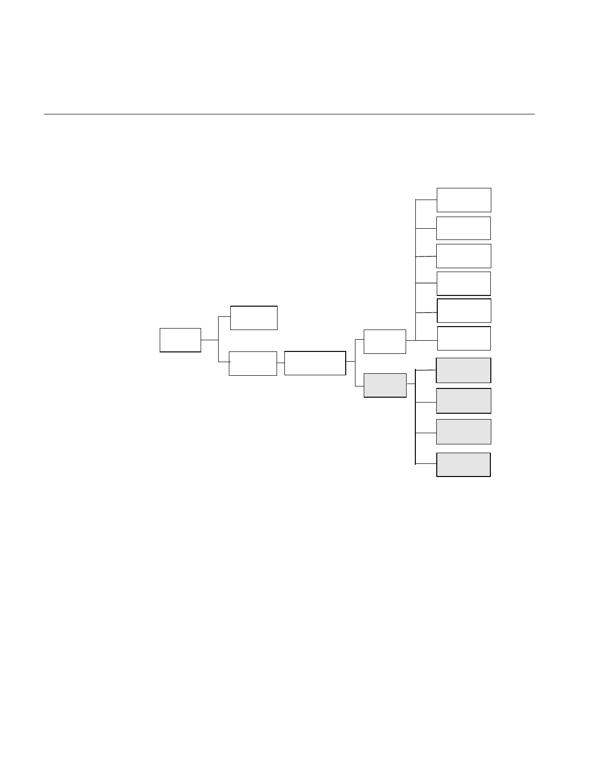
82
Chapter 4: Operating on an Image
IL classes covered in this chapter are mainly those that derive from ilOpImg. The relevant
portion of IL inheritance hierarchy is shown shaded in Figure 4-1.
Figure 4-1 ilOpImg and IL Inheritance Hierarchy
The ilOpImg class defines the basic support for all operator classes. It provides functions
for setting attributes, accessing data, setting bias and clamp levels, and propagating
attributes down an operator chain. Most of these functions are declared protected, so
while they are available for use in a subclass’s implementation, they are not available (or
needed) directly. ilOpImg defines only three sets of public functions:
ilStatus setBias(double biasVal = 0);
double getBias();
ilImage
ilSGIImg
ilTIFFImg
ilFITImg
ilMemoryImg
ilMonadicImg
ilPolyadicImg
ilOpImg
ilFileImg
ilCacheImg
ilPCDImg
ilWarpImg
ilSpatialImg
ilPCDOImg
ilGIFImg
ilMemCacheImg

83
ilStatus setClamp(iflDataType typ=iflDataType(0));
ilStatus setClamp(double min, double max);
int getValidTypes();
int getValidOrders();
Some operators take a bias argument in their constructors and use it in their image
processing algorithms. This bias value is discussed in the sections describing the relevant
operators in the remainder of this chapter. In general, bias is a constant value added to
each pixel luminance value to make it scale correctly. If, for example, the raw pixel
luminance covers values between 100 and 200, some operators are able to scale the
luminance values over the entire depth of pixel luminance values, for example, 0 - 255.
When you scale the luminance values in this way, you need a bias value that adjusts the
initial, raw luminance value, 100, in this example, to zero.
The setClamp() functions allow you to set values that pixels are clamped to if underflow
or overflow occurs. Not all operators allow the clamp values to be modified, so you need
to check that the returned status is not ilUNSUPPORTED if you are assuming you have
changed the values. The first version of setClamp() sets the clamp values to be the
minimum and maximum values allowed for the data type. The default value of typ
means to use the a single bit image type. The second version allows you to specify actual
clamp values. You will not generally need to use either of these functions since most
operators handle overflow and underflow conditions appropriately.
All operators that alter the data range of their inputs compute the worst case minimum
and maximum pixel values to ensure that the processed data can be displayed. For
example, if you multiply two images and then display the result, you can easily end up
with pixel data that is all black. To solve this problem, ilMultiplyImg automatically
computes the worst case minimum and maximum values. When the data is displayed
using ilDisplay, the data is automatically scaled between these values (or those allowed
by the display) so that a meaningful display is produced.
The ilOpImg protected functions that implement these features are
double getInputMin(int idx=0);
double getInputMax(int idx=0);
double getInputScaleMin(int idx=0);
double getInputScaleMax(int idx=0);
The getInput functions return the minimum and maximum luminance values of the
input images. The getInputScale functions return the minimum and maximum
luminance values of the output image.

84
Chapter 4: Operating on an Image
Image Processing Operators Provided with IL
This section discusses all the operators provided with IL. they are grouped functionally
as listed below:
•“Color Conversion and Transformation” on page 85 describes operators that
convert an image from one color model to another.
•“Arithmetic and Logical Transformations” on page 90 describes operators that
perform pixelwise arithmetic or logical computations.
•“Geometric Transformations” on page 98 describes operators that warp, rotate, and
zoom (magnify or minify) an image.
•“Spatial Domain Transformations” on page 106 describes operators that transform
an image in the spatial domain—for example, by sharpening, blurring, convolving,
or rank filtering it in the spatial domain.
•“Edge Detection” on page 117 describes gradient operators such as compass,
Laplace, Roberts, and Sobel.
•“Frequency Domain Transformations” on page 120 describes operators that
incorporate forward or inverse Fourier transforms and frequency-domain filters.
•“Generation of Statistical Data” on page 132 describes the operator that computes
the histogram, mean, and standard deviation of an image.
•“Radiometric Transformations” on page 136 describes operators that perform
radiometric transformations such as histogram normalization and thresholding.
•“Combining Images” on page 146 describes operators that blend, merge, or
combine two images.
•“Constant-valued Images” on page 152 describes an image class that returns a
constant value for all data accesses.
•“Using a Null Operator” on page 152 describes an operator that performs a “null”
operation.
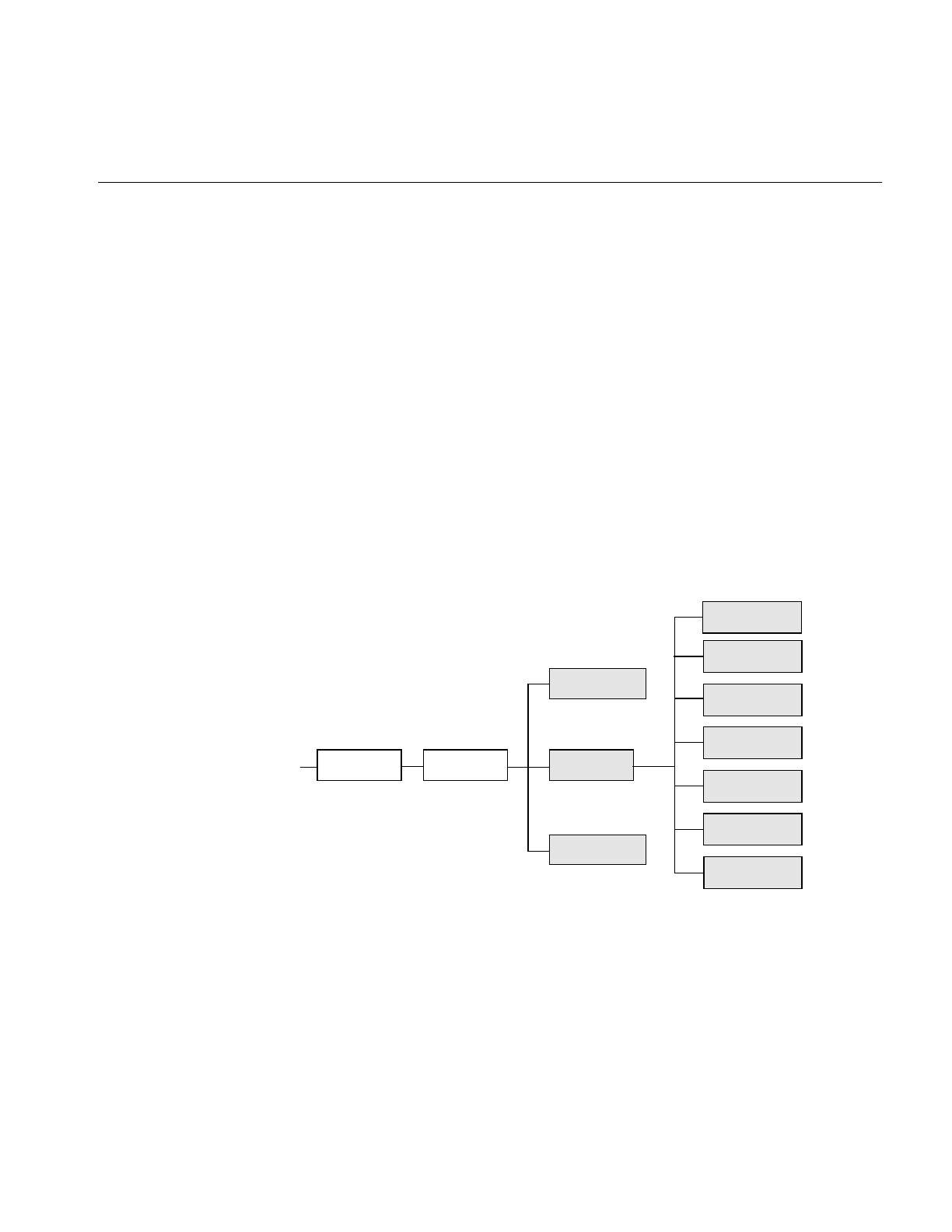
Image Processing Operators Provided with IL
85
Color Conversion and Transformation
IL provides several operators that perform color conversions and color transformations
of IL images. These operators can be summarized as follows:
•The ilColorImg operator converts an existing image from any IL-supported color
model to a requested color model. (See “Color Model” on page 25 for a description
of the color models supported by IL.)
•Several operators, derived from ilColorImg, convert an existing image to one of the
more commonly used color models: CMYK, grayscale, HSV, and RGB.
•The ilFalseColorImg operator converts an image from one multispectral color
model to another.
•The ilSaturateImg operator provides a mechanism to transform the color saturation
of an image.
These color conversion and transformation operators are described in the following
paragraphs. Their positions in IL inheritance hierarchy are shown in Figure 4-2.
Figure 4-2 Color Conversion Operators Inheritance Hierarchy
ilOpImg
ilRGBImg
ilHSVImg
ilGrayImg
ilCMYKImg
ilABGRImg
ilColorImg
ilSGIPaletteImg
ilMonadicImg
ilFalseColorImg
...
ilSaturateImg
ilBGRImg

86
Chapter 4: Operating on an Image
Color Conversion
The base class for the color conversion operators, ilColorImg, defines the generic support
for performing color conversions on image data. It converts data from any supported
color model to any other supported color model, except multispectral.
ilColorImg(ilImage* img, iflColorModel cm);
For example, the following code converts an iflRGB image (theimg) to one whose color
model is iflYCC.
ilColorImg(ilImage* theimg, iflColorModel iflYCC);
The ilColorImg class is not normally used directly to do color-model conversion. Instead,
use derived classes. Each of the six classes derived from ilColorImg performs a specific
conversion. The algorithms used to perform the various conversions are detailed in the
respective reference pages. The six derived classes are summarized below:
•ilABGRImg converts data to the ABGR color model used by Silicon Graphics’
framebuffer.
•ilRGBImg converts an image to RGB.
•ilCMYKImg converts data to the CMYK color model. This color model is used
primarily as an output format for color printers.
•ilGrayImg converts an image to minBlack.
•ilHSVImg converts to the HSVcolor model.
•ilRGBImg converts an image to the iflRGB color model.
•ilSGIPaletteImg converts data to the iflRGBPalette color model. This color model is
suitable for data that is to be displayed in a color-mapped window.
Using any of these derived classes is simple since the only public member function most
of them define is a constructor. To convert an ilImage, call the constructor for the desired
color model and supply as an argument a pointer to the ilImage to be converted. For the
following example, assume that theImg has already been created and that it uses any one
of the supported IL color models:
ilCMYKImg* cnvrtdImg;
cnvrtdImg = new ilCMYKImg(theImg);
In this example, the constructor for the ilCMYKImg class returns a pointer to an
ilCMYKImg, which produces image data converted to the CMYK color model. Similarly,
the constructors for any of the derived classes—ilABGRImg, ilCMYKImg, ilGrayImg,
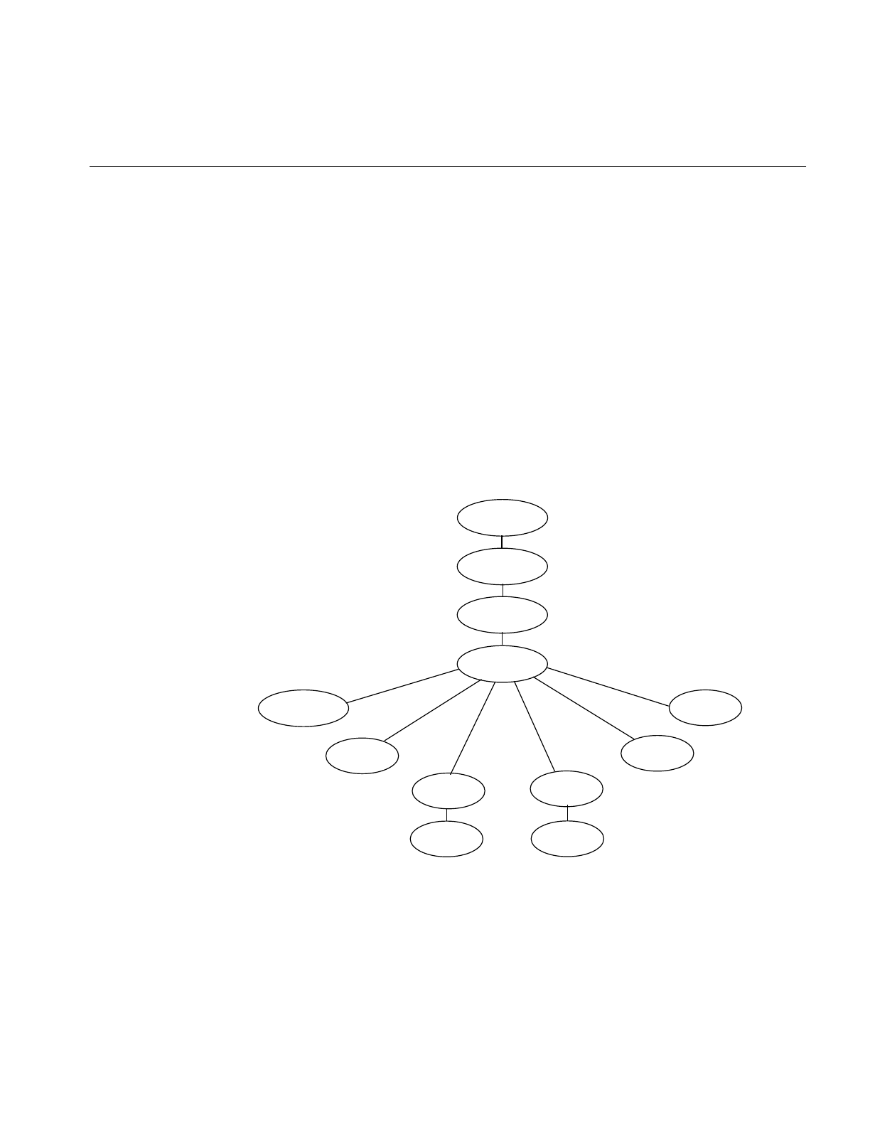
Image Processing Operators Provided with IL
87
ilHSVImg, ilRGBImg, or ilSGIPaletteImg—return a pointer to an object of that class,
which produces converted image data. that is really all there is to it.
If you want to convert to the color models for which there is no derived class (iflRGBA,
iflCMY, ilBRG or iflYCC), use the ilColorImg operator.
If an operator image has two or more inputs with different color models, the color model
of the resulting image depends on the color models of the input images. IL converts the
color models of the input images to a common color model before performing the
operation. The resulting image has this color model. You can use the diagram in
Figure 4-3 to determine how IL determines the common color model. Just find the nodes
for the input images and follow the paths from these nodes to a common node. This
nodes determines the color model of the resulting image. For example, if the color
models of two inputs to an operator are iflHSV and iflYCC, the color model of the
resulting image is iflRGB.
Figure 4-3 Determining the Color Model of Multi-Input Operators
iflMultiSpectral
iflRGBA
iflABGR
iflRGB
iflRGBPalette
iflHSV
iflMinBlack iflCMYK
iflYCC
iflMinWhite
iflBGR
iflCMY

88
Chapter 4: Operating on an Image
ilFalseColorImg
The ilFalseColorImg operator performs false coloring of multispectral images. It
accomplishes this by computing the weighted sum of the input channels for each channel
of the resulting false-color image. The constructors for ilFalseColorImg, except the NULL
constructor, or take a pointer to the input image and the arguments that define the
conversion algorithm:
ilFalseColorImg();
ilFalseColorImg(ilImage *img, int numColumns, int numRows,
const float* xformMatrix, const float* bias=NULL);
The conversion is defined by the transformation matrix, xformMatrix. This matrix has
dimensions numColumns x numRows. Each row of this matrix defines a set of weights
used to produce one channel of the output. Each weight is multiplied by the pixel values
in the corresponding input channel, and the weighted sum forms the output channel.
The conversion may also include a bias vector, bias. This vector contains a constant value
for each input channel that is added to each input value before it is weighted. Thus, the
transformation equation for each channel of the output image is:
where C and R are numColumns and numRows, respectively.
An image transformed by ilFalseColorImg appears in Figure 4-4.
OutputCx1TCxR InputCx1BCx1
+()=
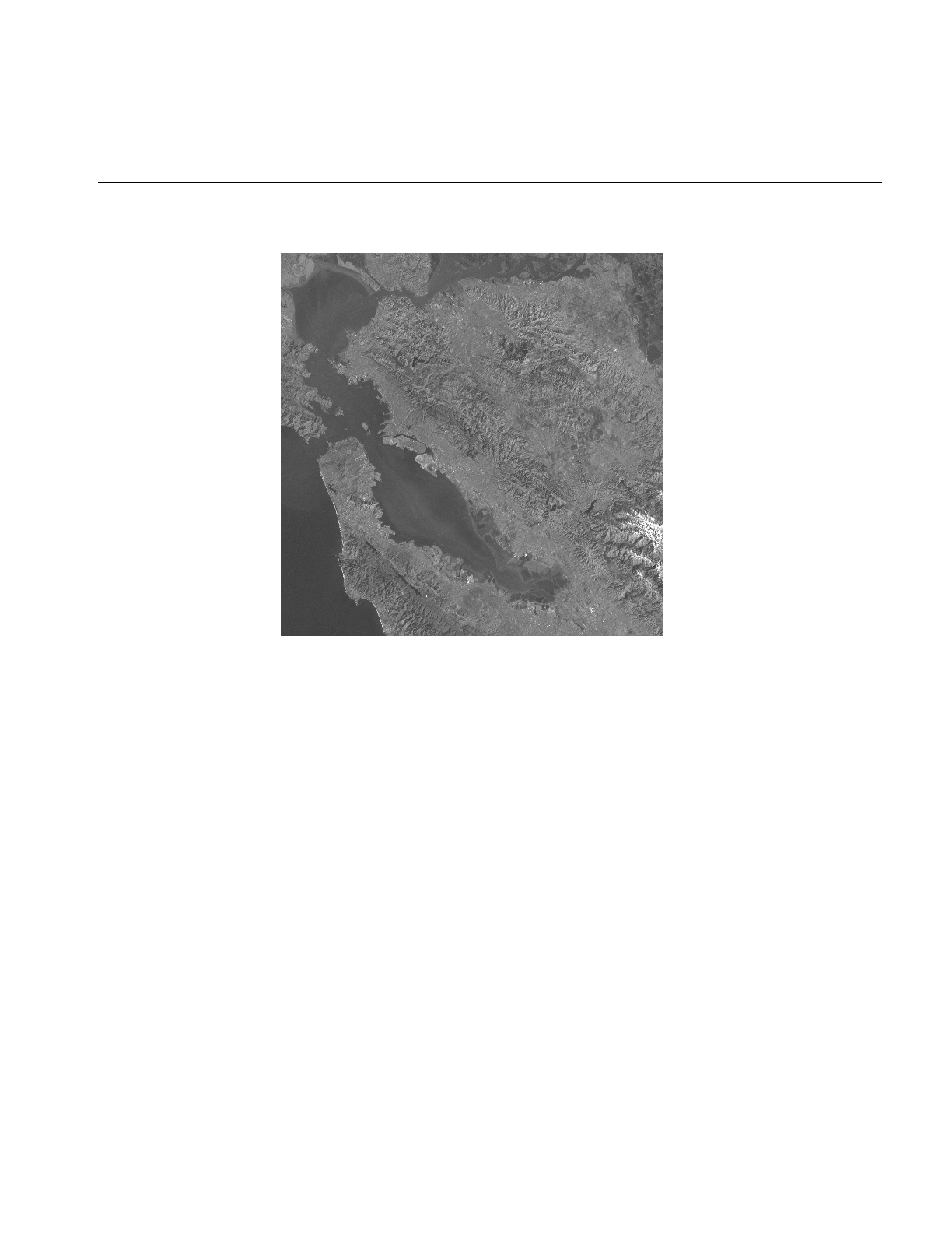
Image Processing Operators Provided with IL
89
Figure 4-4 A Falsely Colored Image
ilSaturateImg
This operator performs a color saturation of its input. If the input color model is not RGB,
the input is first converted to RGB. The constructor for ilSaturateImg takes a pointer to
the input image and an initial saturation value:
ilSaturateImg(ilImage* img=NULL, float sat=1);
The transformation is defined as:
Equation 1
lum = .3redin + .59greenin - .11bluein
Equation 2
redout = lum + (redin - lum)sat

90
Chapter 4: Operating on an Image
Equation 3
greenout = lum + (greenin - lum)sat
Equation 4
blueout = lum + (bluein - lum)sat
You can set the saturation value interactively with setSaturation():
void setSaturation(float saturation);
The current value of the saturation factor can be queried with getSaturation():
float getSaturation();
A value of zero completely desaturates the image (equivalent to ilGrayImg), a value of
one leaves the image unchanged, and values greater than one increase the color
saturation of the image. Output values are clamped to the minimum and maximum
values of the operator image, which by default are simply inherited from the input.
Arithmetic and Logical Transformations
There are numerous IL operators that perform pixelwise arithmetic transformations of
image data. Some of these require two input images—for example, to add them
together—while others perform computations on a single image’s data, such as
determining the absolute value. In the inheritance hierarchy shown in Figure 4-5,
operators that inherit from ilPolyadicImg take two images as inputs and those that
derive from ilMonadicImg take only one.
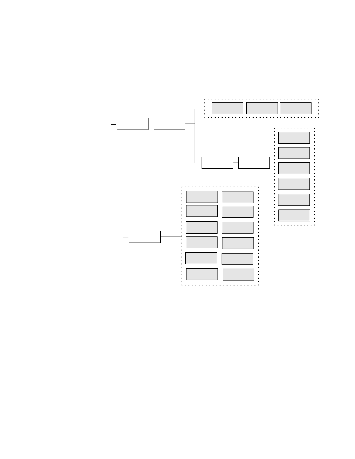
Image Processing Operators Provided with IL
91
Figure 4-5 Arithmetic and Logical Operators Inheritance Hierarchy
When using one of the dual-input operators, you might want to use an ilConstImg as one
of the inputs. An ilConstImg returns the same value for all of its pixels, so you can use it
to multiply each of an image’s pixels by a constant value, for example. For more
information on how to create an ilConstImg, see “Constant-valued Images” on page 152.
Single-input Operators
The single-input arithmetic operators are listed in Table 4-1, along with the operation
they perform on each pixel of image data and the pixel data types each operation can
ilPolyadicImg
ilMaxImg
ilDivImg
ilAndImg
ilAddImg
ilAbsImg
ilSubtractImg
ilExpImg
ilMonadicImg
...
ilOrImg
ilMinImg
ilLogImg
ilInvertImg
ilSqRootImg
ilXorImg
ilPowerImg
ilSquareImg
ilMultiplyImg
ilNegImg
ilLutImg ilArithLutImg
ilBlendImg
ilAbsImg ilHistLutImg
ilDyadicImg
ilOpImg
...

92
Chapter 4: Operating on an Image
produce. The last five operators in Table 4-1 (ilSquareImg, ilSqRootImg, ilExpImg,
ilPowerImg, and ilLogImg) descend directly from ilArithLutImg. The ilArithLutImg
abstract class optimizes the performance of operators that derive from it by pulling
precomputed square, square root, exponent, power, and log values from a lookup table.
This is much more efficient than computing values on a per-pixel basis.
The ilArithLut class in turn inherits from ilLutImg. Consequently, the last five operators
in Table 4-1 inherit the ability to be accelerated further in the CPU or in specialized
graphics hardware. See “Radiometric Transformations” on page 136 and “Using
Hardware Acceleration” on page 253 for details about ilArithLutImg and hardware
acceleration, respectively.
An example of processing by an arithmetic operator is given in Figure 4-6, which shows
an original image constructed from simulation data processed with ilNegImg.
a. iflChar iflShort, iflLong, iflFloat, and iflDouble are the signed data types.
b. These operators allow you to apply scale and bias values to the pixelvalue, so that it becomes
scale*pixelvalue+bias.
Table 4-1 Single-input Arithmetic Operators and Their Valid Output Data Types
Operator Operation Performed Valid Data Types
ilAbsImg absolute value iflUChar, iflUShort, iflULong,
iflFloat, iflDouble
ilNegImg two’s complement any signed data typea
ilInvertImg one’s complement iflBit, iflChar, iflUChar, iflShort,
iflUShort, iflLong, iflULong
ilSquareImg (pixelvalue)2any type except iflBit
ilSqRootImg any type except iflBit
ilExpImgbbase(pixelvalue) any type except iflBit
ilPowerImgb(pixelvalue)power any type except iflBit
ilLogImgblogbase(pixelvalue) any type except iflBit
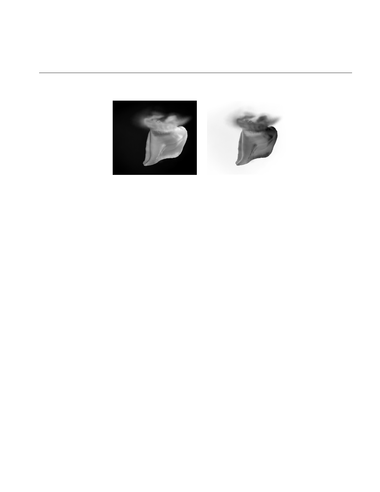
Image Processing Operators Provided with IL
93
Figure 4-6 A Positive and Negative Image Pair
The only public member function defined in ilAbsImg, ilNegImg, ilInvertImg,
ilSquareImg, and ilSqRootImg is a constructor that takes a single argument, the input
image. Thus, to include any of these operators in a chain, you simply call its constructor
and pass, as the argument, a pointer to the input ilImage. In this example, assume that
inputImg is a pointer to an already existing ilImage:
ilAbsImg* someAbsImg = new ilAbsImg(inputImg);
The constructors for the ilAbsImg, ilNegImg, ilInvertImg, ilSquareImg, and ilSqRootImg
classes all return a pointer to the operator image.
The constructors for the remaining three classes—ilExpImg, ilPowerImg, and
ilLogImg—take three additional arguments, all of type double. The second argument for
each of these constructors specifies base or power, the third specifies scale, and the fourth
bias.
ilExpImg(ilImage* inImg = NULL, double expBase=0,
double scl=1., double bs=0.);
ilPowerImg(ilImage* inImg = NULL, double pow = 2,
double scl=1., double bs=0.);
ilLogImg(ilImage* inImg = NULL, double logBase=0,
double scl=1., double bs=0.);
The ilExpImg, ilPowerImg, and ilLogImg classes define a function for setting the value
of the second parameter after the operator is created, so that you can dynamically alter
the computation:
void setBase(double expBase=0); // for ilExpImg
void setPower(double power=2); // for ilPowerImg
void setBase(double logBase=0); // for ilLogImg

94
Chapter 4: Operating on an Image
Dual-input Operators
As their names suggest, the dual-input operators ilAddImg, ilSubtractImg,
ilMultiplyImg, and ilDivImg perform standard arithmetic computations—addition,
subtraction, multiplication, and division of two images. The constructors for each of
these classes take as arguments pointers to the two input images, which can be different
sizes but must have the same number of channels. If they are different sizes, by default
the output image is the larger of the two sizes; the smaller input image is padded with
its fill value, and then the operator performs its computation on corresponding pixels in
the two images. You can explicitly set the desired output size with ilImage.setSize().
You may also offset one image with respect to the other using the following
ilPolyadicImg methods:
void setOffset(int x, int y, int z = 0, int input = 0);
void getOffset(int &x, int &y, int &z, int input = 0);
setOffset() offsets the first image with respect to the second by x,y, and z if input is 0. If
input is 1, the second image is offset with respect to the first. getOffset() queries the
dual-input operator for its offsets. If input is 0, the offset of the first image relative to the
second is given; if input is 1, the offset of the second image relative to the first is given.

Image Processing Operators Provided with IL
95
Here are the constructors for the dual-input operators:
ilAddImg(ilImage* in1 = NULL, ilImage* in2 = NULL,
double bias=0);
ilSubtractImg(ilImage* in1 = NULL, ilImage* in2 = NULL,
double bias=0);
ilMultiplyImg(ilImage* in1 = NULL, ilImage* in2 = NULL);
ilDivImg(ilImage* in1 = NULL, ilImage* in2 = NULL, ckDiv=1);
ilAddImg adds the bias value to the sum found by adding the corresponding pixels of
in1 and those of in2. The ilSubtractImg operator subtracts the corresponding pixels of in2
from every pixel of in1 and then adds the bias value. ilMultiplyImg multiplies the pixels
in the two input images, and ilDivImg divides the pixels of in1 by the corresponding
pixels of in2. All of these operators can produce an image containing any data type except
iflBit. An example using ilAddImg appears in Figure 4-7. The two original images appear
as well; one is the flipped version of the other.
The ckDiv argument for ilDivImg’s constructor specifies whether the operator should
check for division by zero. By default, it does check and responds as described below:
•If the divisor is zero and the dividend is positive, the quotient is set to the maximum
value possible for the final image’s data type.
•If the divisor is zero and the dividend is negative, the quotient is set to the
minimum value possible for the final image’s data type.
•Zero divided by zero produces a zero.
You can use setCheck() to change whether this check is made.
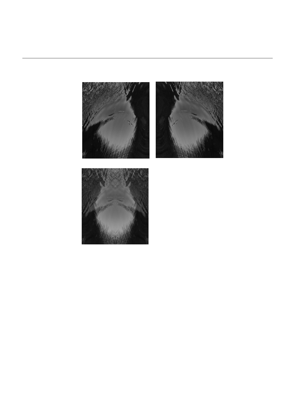
96
Chapter 4: Operating on an Image
Figure 4-7 Adding Two Images
The two classes ilMaxImg and ilMinImg compare each corresponding pixel in the two
input images and select the greater or the lesser value, respectively. Their constructors
take pointers to the two input images as arguments. These input ilImages must have the
same number of channels. The output image can contain any data type except iflBit.
(There are also simple, in-line functions defined in the header file il/ilMinMax.h that
compare two values and return the greater or the lesser one. See “Minimum and
Maximum Comparisons” on page 364 for more information about these functions.) An
Original 1 Original 2
Added Images
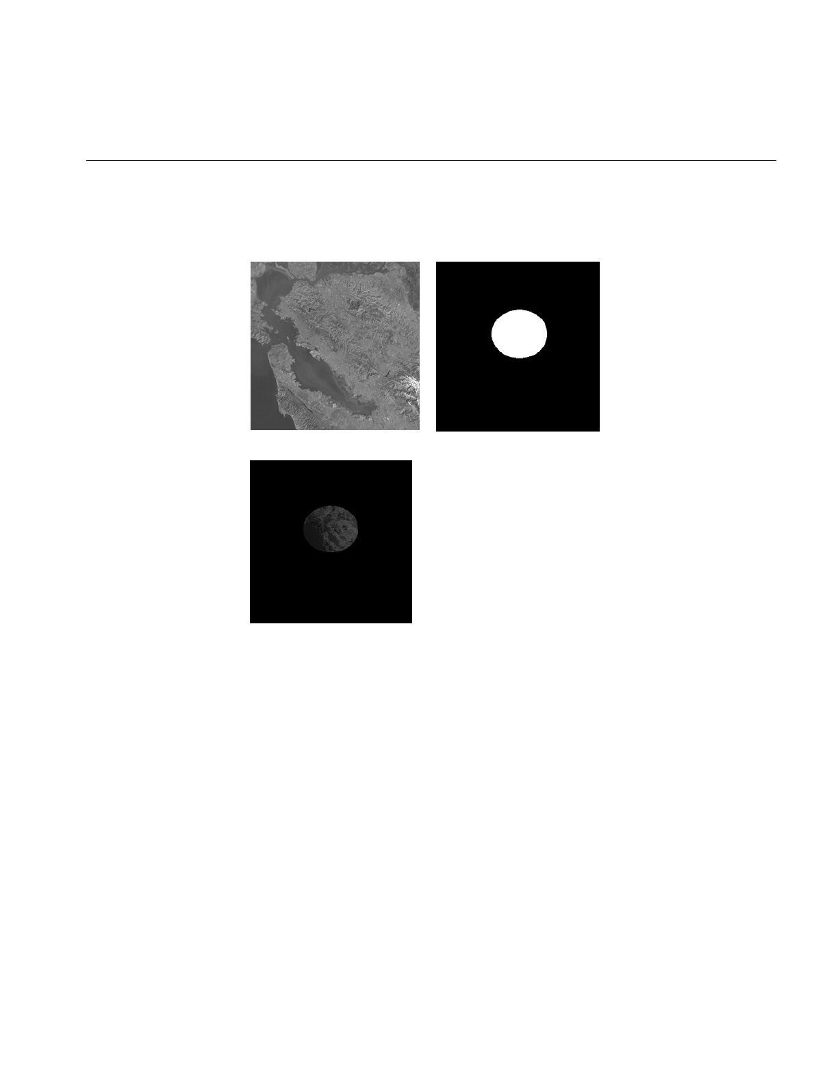
Image Processing Operators Provided with IL
97
example of using ilMinImg appears in Figure 4-8. Two original images are shown,
followed by the image that results if you apply ilMinImg to these images.
Figure 4-8 Minimum of Two Images
Similarly, the logical-operator classes—ilAndImg, ilOrImg, and ilXorImg—perform their
computations (logical AND, OR, and exclusive-OR) by combining each corresponding
pixel in the two input images. The constructors for these classes take pointers to the two
input images as arguments. The input ilImages must have the same number of channels;
the output image can contain any of the following data types: iflChar, iflUChar, iflShort,
iflUShort, iflLong, or iflULong. Figure 4-9 shows an example of using ilAndImg and
ilOrImg on the original images from Figure 4-7.
Original Image Original Mask
Minimum of Image and Mask
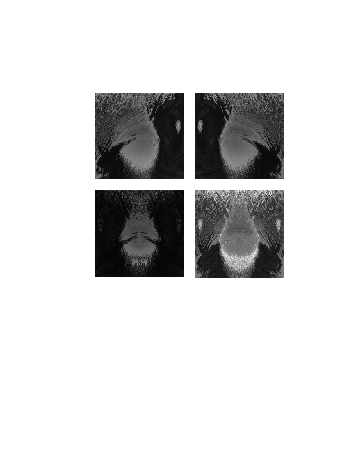
98
Chapter 4: Operating on an Image
Figure 4-9 Logical AND and OR of Two Images
Geometric Transformations
The heart of a geometric transformation, or warp, is the algorithm that maps output
image coordinates to input coordinates. (See Figure 4-10.) The general support for such
transformations is encapsulated in the abstract class, ilWarpImg. Classes that derive from
ilWarpImg— ilTieWarpImg, and ilRotZoomImg—implement specific warping
algorithms;. These algorithms are most efficient for images that are relatively square.
Original Image 1 Original Image 2
Logical AND Logical OR
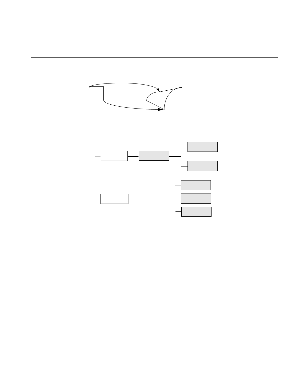
Image Processing Operators Provided with IL
99
Figure 4-10 A Warped Image
The warping classes are shown in Figure 4-11 and discussed in the following sections.
Figure 4-11 Geometric Operator Inheritance Hierarchy
Warping an Image
The ilWarpImg class, from which ilTieWarpImg, and ilRotZoomImg derive, performs up
to a two-dimensional, seventh-order warp. The output image space is mapped to the
input image space with a transformation defined by two sets of polynomials (which can
be up to seventh order), one for the x-dimension and one for the y-dimension. Since the
coefficients for the polynomials are not always integers, the addresses computed for the
output space sometimes contain fractional components. Therefore, a resampling method
must be applied to convert these fractional addresses into meaningful pixel locations.
ilOpImg
...
ilTieWarpImg
ilRotZoomImg
ilWarpImg
ilPerspWarp
ilWarp
...
ilAffineWarp
ilPolyWarp

100
Chapter 4: Operating on an Image
To use ilWarpImg, you must choose a resampling algorithm and specify the coefficients
of the warping polynomials. The constructor takes as its arguments a pointer to the input
image and a constant that corresponds to a resampling method:
ilWarpImg(ilImage* img=NULL, ilResampType rs=ilNearNb,
ilWarp* warp=NULL);
The ilResampType enumerated type is defined in the header file il/iflDataTypes.h and
shown in “Resampling Methods” on page 100. It has these six members:
•ilNearNb (nearest neighbor)
•ilBiLinear
•ilBiCubic
•ilMinify
•ilUserDef (for a resampling algorithm you implement)
If you choose a bicubic resampling method, you can use setBicubicFamily() to fine-tune
its algorithm.
ilWarpImg performs output-driven image warps. It uses the abstract. helper class,
ilWarp, to define the specific nature of a given warp. An image of any data type may be
given as input. The proper data conversions will be performed to ensure output is one of
the following valid data types: ilUChar, ilUShort, ilShort or ilFloat.
ilWarpImg is a cached, image operator. It may be linked into operator chains.
Resampling Methods
The ilWarpImg class supports five built-in resampling methods:
•nearest neighbor
•bi-linear (the default)
•bi-cubic interpolation
•filtered minification (ilMinify)
•auto resampling

Image Processing Operators Provided with IL
101
The resampling type can be altered with setResampType(). ilWarpImgSetResampType().
Support for user-defined resampling methods is also provided by the setResampFunc()
function.
Nearest neighbor is the fastest method, but produces the lowest quality result. This
method merely copies the value of the input pixel that is closest to the computed address.
It is most useful when performance is more important than image quality, as for instance
when the warp is under interactive control by a human. When the warping parameters
have been adjusted to satisfaction, the final output might be produced with the bi-linear
or bi-cubic method.
The bi-linear method interpolates over a 2x2 neighborhood around the computed input
address, using a simple weighted average. This method is somewhat slower than nearest
neighbor, but produces a much higher quality result.
The bi-cubic method interpolates over a 4x4 neighborhood, using an interpolation kernel
that approximates a two-dimensional bi-cubic spline. For a given (x, y) point, the
interpolation is performed by first interpolating four lines starting at floor(y)-1 and
ending at floor(y)+2; each line runs from floor(x)-1 and ends at floor(x)+2. The resulting
values are then processed vertically to produce the resulting output point.
In order to speed up the processing, the cubic convolution co-efficients are precomputed
to a 1/256 pixel accuracy and stored in a table. This provides more than adequate
accuracy for geometric precision. The co-efficient generation is from equation (8) in the
paper:
Mitchell, D. and A. Netravali, “Reconstruction Filters in Computer Graphics.”Computer
Graphics, Vol. 22, No. 4, pp. 221-228.
The setBicubicFamily() function allows the B and C co-efficients of equation (8) in the
cited paper to be defined, allowing a choice of various bicubic resampling.
Filtered minification is used when unaliased minification is desired. The input image is
filtered and minified. The user can specify a filter or, if none is specified, a box filter is
used. The size of the box filter, depends on the minification factor and it ensures that the
entire input image is sampled. If the box filter or kernel is used, the operation can be
speeded up by sub-sampling the kernel. By using the setMaxSamples() function, the
number of image pixels are averaged to produce an output pixel can be set. So if the
number of samples is set to 10, even when using a 5 x 5 kernel, only 10 image pixels used
to compute the filtered result.

102
Chapter 4: Operating on an Image
Note: When specifying your own kernel, each zero value in the kernel results in one less
multiply/add computation. So, sprinkling zeros around the kernel achieves sub-
sampling.
If you choose the ilMinify resampling method, you can use setMinifyKernel() to specify
your own kernel instead of the default box (all 1s) kernel. In the default case, the kernel
size is dynamically adjusted so that the entire input is sampled (that is, all the input
image pixels are used to compute the output). If you use the default kernel, you can
speed up the operation by using setMaxSamples() to set the number of input image
pixels to be averaged to produce a single output pixel. For example, if you set the
maximum number of samples to 10 and you are minifying by a factor of 8, thus
necessitating the use of an 8 x 8 kernel, only 10 input pixels (instead of 64) uniformly
interspersed throughout the 8 x 8 area are averaged to produce one output pixel.
To define your own resampling method, use setResampFunc() and pass in a pointer to
your algorithm. The reference page for ilWarpImg explains what the supported
algorithms are, which one you might want to use, and how to define your own
algorithm.
You can dynamically change and retrieve the resampling method with setResampType()
and getResampType(), which are inherited from ilWarpImg:
void setResampType(ilResampType rs);
ilResampType getResampType();
Additionally, ilWarpImg lets you determine the amount of error allowed in a warp
performed in graphics hardware with setAddressError(). Its one parameter,
maxPixelsOff, determines by how many pixels the warped data may be incorrect. The
previously set parameter can be retrieved with getAddressError():
void setAddressError(float maxPixelsOff);
float getAddressError();
For backward compatibility, you can define the coefficients of the warping polynomial
using the ilPolyWarpImg.setCoeff() function:
void setCoeff(const ilCoeff_2d& xcoeff, const ilCoeff_2d& ycoeff);
You can query the ilWarpImg object for its coefficients with ilPolyWarpImg.getCoeff()
and for the order of its polynomial with ilPolyWarpImg.getPolyOrder():
void getCoeff(ilCoeff_2d& xcoeff, ilCoeff_2d& ycoeff);
int getPolyOrder();

Image Processing Operators Provided with IL
103
The ilPolyCoeff2SD structure contains floating point numbers for the coefficients. It is
defined in the header file il/ilPolyDef.h, as shown below:
struct ilPolyCoeff2D {
float con,
y, x,
y2, xy, x2,
y3, xy2, x2y, x3,
y4, xy3, x2y2, x3y, x4,
y5, xy4, x2y3, x3y2, x4y, x5,
y6, xy5, x2y4, x3y3, x4y2, x5y, x6,
y7, xy6, x2y5, x3y4, x4y3, x5y2, x6y, x7;
};
The ilTieWarpImg class performs a two-dimensional warp, but it does not allow you to
specify the coefficients of the warping polynomial directly. Instead, you specify pairs of
tie points in the input and the output images that should match after the image is warped
as shown in Figure 4-12. The coefficients of the polynomial, which you can choose to be
first- to seventh-order, are then computed from these tie points. The minimum number
of pairs of points necessary to determine the coefficients of a polynomial of order ord is
given by the formula:
Thus, you need to specify at least three pairs of points for a first-order polynomial, six
pairs for a second-order, and so on.
The constructor for ilTieWarpImg takes the same arguments as that for ilWarpImg. After
creating an ilTieWarpImg operator, you must specify the tie points from which the
warping polynomial is computed. For this, use setTiePoints):
void setTiePoints(const iflXYfloat* uv,
const iflXYfloat* xy, int n);
This function takes pointers to arrays of n tie points in the input image (xy) and the
output image (uv) and computes the polynomial’s coefficients. (The data type iflXYSfloat
is defined in the header file il/iflCoord.h as an (x, y) coordinate pair of data type float.) The
function isWellDefined() can be used to check if the polynomial coefficients can be
computed from the specified tie points. If the polynomial is successfully computed, one
is returned; if not, zero is returned. Before you call setTiePoints(), you might want to set
the order of the polynomial that will be computed by calling setPolyOrder() and passing
in 1, 2, 3, 4, 5, 6, or 7 as the desired order. If you do not explicitly set the order, a first-order
pairs ord 1+()ord 2+()
2
--------------------------------------------------
=
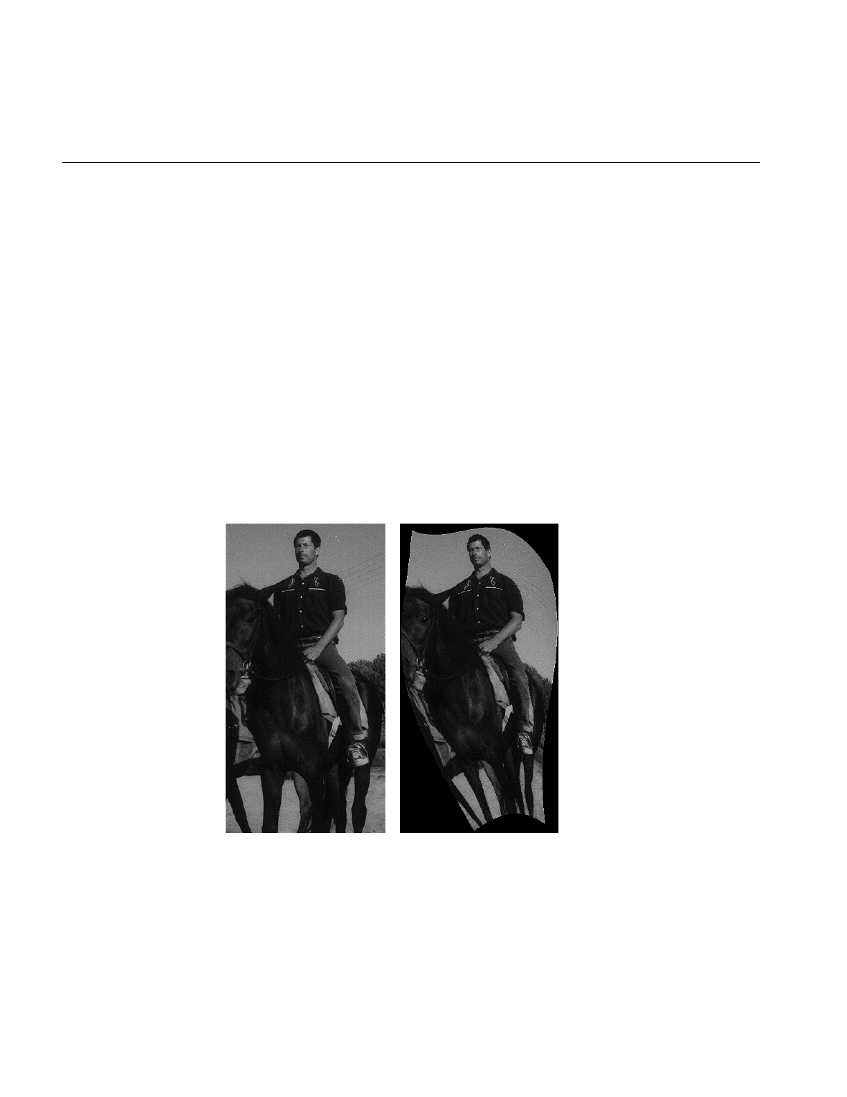
104
Chapter 4: Operating on an Image
polynomial is used. The function getPolyOrder() returns the order of the warping
polynomial.
To move the tie points, use moveTiePoint(), defined as follows:
ilStatus moveTiePoint(float u, float v, float x, float y, int idx);
ilWarpImg defines functions (which ilTieWarpImg and ilRotZoomImg inherit) that,
given a point in the input (or output) image, compute the corresponding point in the
output (or input) image, using the mapping specified by the polynomial:
void evalUV(iflXYfloat& uv, const iflXYfloat& xy);
void evalXY(iflXYfloat& xy, const iflXYfloat& uv);
The function evalUV() takes the input image point xy and returns by reference the
corresponding point uv in the output image. Similarly, evalXY() computes the input
image point, xy, from the output image point, uv.
Figure 4-12 shows the result of applying ilTieWarpImg to an image.
Figure 4-12 Warping an Image
Original Image Warped Image

Image Processing Operators Provided with IL
105
Rotating, Zooming, and Flipping an Image
Unlike the various warping classes, the ilRotZoomImg operator is limited to performing
two-dimensional affine transformations on an image. This single operator can rotate,
zoom (magnify or minify), and mirror (or flip) image data:
ilRotZoomImg(ilImage* img = NULL, float rotAngle=0,
float horizontalZoom=1, float verticalZoom=1,
ilResampType rs=ilNearNb);
The input image, img, is rotated by rotAngle degrees in a counterclockwise direction and
magnified or minified in the appropriate dimension by the horizontalzoom and
verticalzoom factors. The default resampling method is nearest neighbor (ilNearNb). This
method, when there is no hardware acceleration, chooses ilMinify resampling for pure
minification (x and y zoom factors < 1.0 and rotation angle = 0.0) and ilNearNb
otherwise. If there is hardware acceleration, ilBiLinear is chosen for pure minification
and ilNearNb otherwise. This operator is especially efficient when the rotation is a
multiple of 90 degrees and when the resampling method is ilNearNb.
Functions are provided for you to dynamically change all the parameters:
void setAngle(float rotAngle);
void setZoom(float horizontal, float vertical);
void setZoom(float zoom);
void setCenter(float h, float v);
An analogous set of functions is provided to retrieve the parameters:
float getAngle();
void getZoom(float& horizontal, float& vertical);
int getCenter(float& h, float& v);
You can also select a portion of the image to be operated on by using setSize() (inherited
from ilImage) and setCenter(). Alternatively, you can ask for only the desired portion
using getTile() or copyTile() with the appropriate arguments, or you can define a region
of interest.
The setSize() and setCenter() functions limit the transformation to the area specified
with setSize(), centered on the point given in setCenter(). The center point is specified in
the input image’s coordinate space. These functions also translate the image’s coordinate
space so that the image’s origin becomes the corner of the region specified by setCenter()
and setSize(). You can clear the center point set with setCenter() by calling clearCenter().
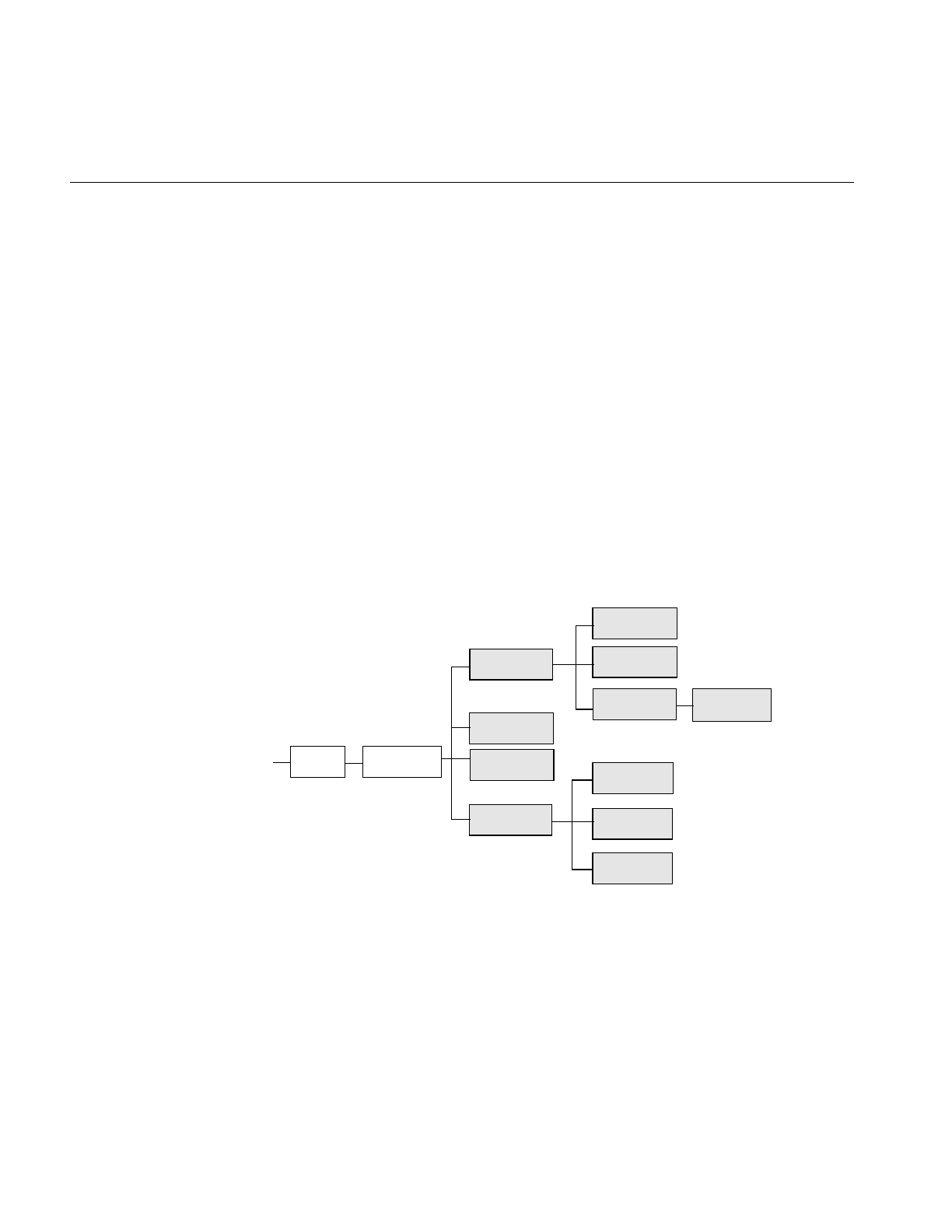
106
Chapter 4: Operating on an Image
You can zoom the input image to a particular size by calling sizeToFit():
void sizeToFit(float width, float height,
int keepAspect=FALSE);
You specify the desired image width and height with width and height. If you want the
image to keep its aspect ratio, set keepAspect to TRUE. The default behavior allows the
image’s aspect ratio to change.
Spatial Domain Transformations
Spatial operators transform image data by computing a weighted sum of the pixels in the
neighborhood surrounding the target pixel. The size of the neighborhood and the
weights used for neighboring pixel values are defined by the kernel. Some spatial
operators predefine their kernels while others allow the user to specify them. In addition,
a method for handling pixels at the edge of an image must be specified, since a pixel’s
neighborhood is undefined beyond the edge of a page. The spatial operators provided
with IL are shown in Figure 4-13.
Figure 4-13 Spatial Domain Operator Inheritance Hierarchy
ilOpImg
...
ilSharpenImg
ilBlurImg
ilSpatialImg
ilConvImg
ilRankFltImg
ilGBlurImg
ilMaxFltImg
ilMedFltImg
ilMinFltImg
ilDilateImg
ilErodeImg
ilSepConvImg

Image Processing Operators Provided with IL
107
The ilSpatialImg class, which is an abstract class, defines the basic support for spatial
operators that derive from it. The public functions it defines are those that allow you to
set and retrieve the kernel and the edge-handling method.:
void setKernel(ilKernel* kern=NULL);
void setKernelSize(int x, int y, int z=1);
void getKernelSize(int& x, int& y, int& z);
void getKernelSize(int& x, int& y);
void setEdgeMode(ilEdgeMode eMode = ilPadSrc);
ilEdgeMode getEdgeMode();
Note: Some operators predefine their kernel and thus do not allow you to set it.
The ilKernel class defines a kernel as consisting of the following elements:
• the size of the kernel in the x, y, and z dimensions
• the size of the data type used to specify kernel weights
• a pointer to the data specifying the weights
The x, y, and z dimensions should be odd numbers so that a neighborhood can be exactly
centered on a single, target pixel. If they are even numbers, the data may be shifted. See
the reference page for ilKernel, il/ilKernel.h, and “Auxiliary Classes” on page 358 for more
information about this class.
The origin of an ilKernel normally falls at its center pixel. The origin can be specified with
ilKernel’ssetOrigin() function to correspond to any of the pixels in the kernel. The
arguments x,y, and z indicate the origin’s offset from the upper-left-front corner of the
kernel. getOrigin() returns the offset by reference.
void setOrigin(int x, int y, int z=0);
void getOrigin(int &x, int &y, int &z);
ilSpatialImg’ssetEdgeMode() function specifies how the neighborhood is defined for
pixels at the edge of the image. Explanations of the supported edge modes, which are
defined in ilTypes.h, follow:
ilReflect Sufficient data near the edge of the image is reflected so that a full-sized
output image can be processed without producing artifacts at the image
edge. This mode gives the best results for most operators.
ilWrap Sufficient data is taken from the opposite edge of the source image so
that a full-sized output image can be processed.
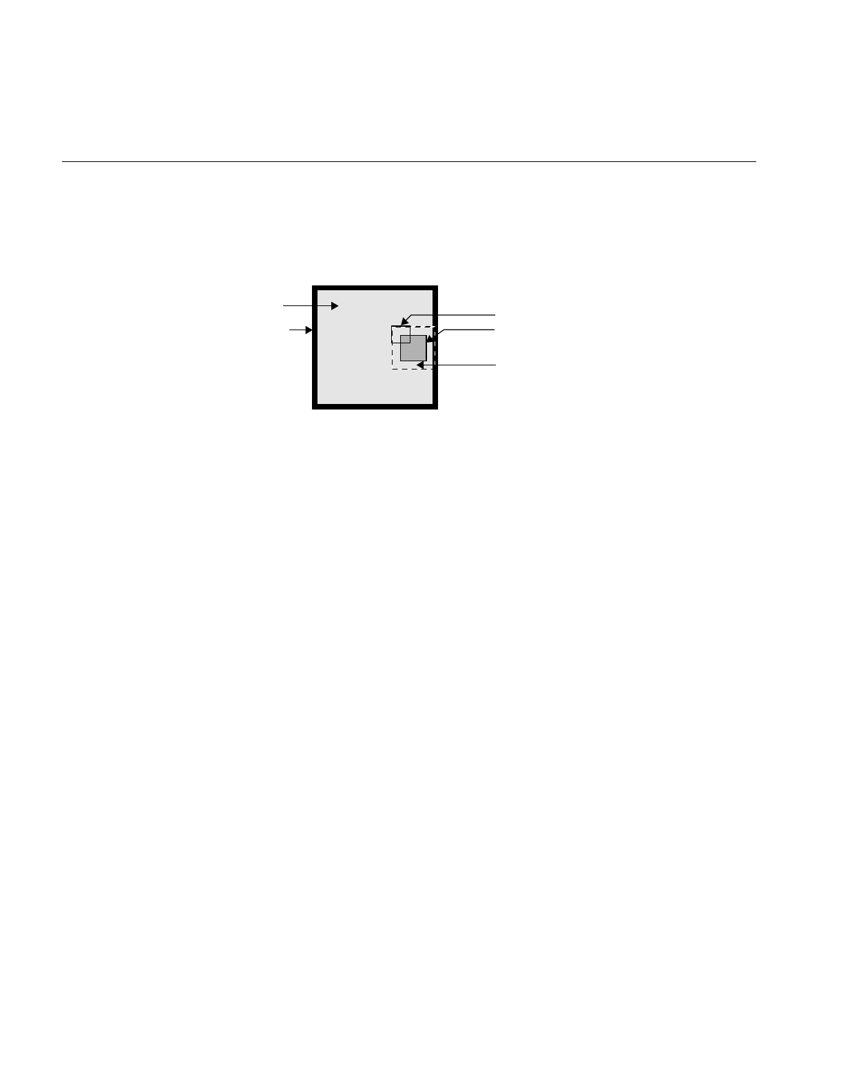
108
Chapter 4: Operating on an Image
ilPadSrc The edge of the input image is padded with the input image’s fill value
so that a full-sized output image can be processed (see Figure 4-14). See
“Fill Value” on page 29 for more information on an image’s fill value.
Figure 4-14 The ilPadSrc Edge Mode
ilNoPad No padding is done, and the output image shrinks by the size of the
kernel minus one in each dimension.
ilPadDst Similar to ilNoPad, except that the output, image’s border is sufficiently
padded with its fill value so that the final image is the same size as the
source image.
Convolving an Image
The ilConvImg operator performs general image convolution. This class is not an
abstract class, so you can use it directly to convolve image data. The constructor for
ilConvImg, which is its only public member function, is shown below:
ilConvImg(ilImage* inputImage=NULL,
ilKernel* inputKernel=NULL, double biasVal = 0.,
ilEdgeMode eMode=ilPadSrc);
This function takes a pointer to the source or input image, a pointer to the kernel, and an
enumerated type that matches one of the supported edge modes. The other argument,
biasValue, is added to the weighted sum (image data multiplied by kernel weight) for
each neighborhood. You can set the bias value with the setBias() function.
You can also perform certain convolutions more efficiently with a separable kernel (one
that is specified by row and column vectors). ilSepConvImg, descended from
ilSpatialImg, provides this feature. Its constructor accepts the input image, the row and
column kernels, the sizes of the kernels, an optional bias value, and an optional edge
mode:
Page Being Processed
Image Data Kernel
Filled Border
Padded Data

Image Processing Operators Provided with IL
109
ilSepConvImg(ilImage *inputImg = NULL,
float *xkernel=NULL, float *ykernel=NULL, int xsize=1,
int ysize=1, double biasVal=0.0,
ilEdgeMode eMode = ilPadSrc)
float *zkernel = NULL, int zsize = 1);
As shown, the default bias is 0.0, and the default edge mode is ilPadSrc. The default
kernel size for each kernel is 5. This operator is especially efficient for kernel sizes 3 x 3,
5 x 5, and 7 x 7.
ilSepConvImg also defines a set of functions to set and get the kernel vectors:
void setXkernel(float *xval);
void setYkernel(float *yval);
void setZkernel(float *zval, int n = 0);
float* getXkernel();
float* getYkernel();
float* getZkernel();
setXkernel() allows you to change the row kernel; getXkernel() returns its value.
setYkernel() allows you to change the column kernel; getYkernel() returns its value.
setZkernel() allows you to change the depth kernel; getZkernel() returns its value. If you
replace any kernel with one that has a different size, use ilSpatialImg.setKernelSize()
(inherited from ilSpatialImg) to update the sizes.
Blurring or Sharpening an Image
The two blurring operators, ilBlurImg and ilGBlurImg, both blur an image by
performing a convolution, but they use different kernels and algorithms for the
convolution. ilBlurImg convolves the image with a blurring kernel using the general
convolution algorithm defined by ilConvImg. ilGBlurImg (descended from
ilSepConvImg) convolves an image with a separable two-dimensional Gaussian kernel.
Because ilGBlurImg uses a separable kernel, it is generally more efficient than ilBlurImg.
Although different methods are used, often the blurred results do not look significantly
different. The reference pages for these classes provide more detailed information on the
kernels and convolution algorithms used. Figure 4-15 shows an original image that is
used as an example in the following pages.
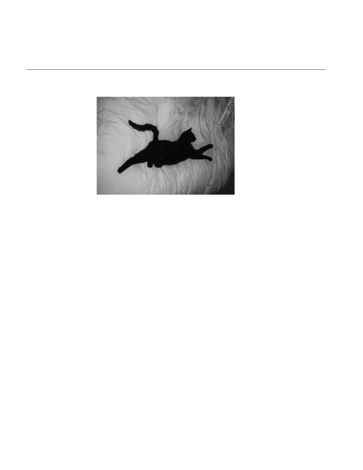
110
Chapter 4: Operating on an Image
Figure 4-15 An Original Image
The ilBlurImg and ilGBlurImg classes have slightly different interfaces:
ilBlurImg(ilImage *img = NULL, float blur=1.,
float radius=2., ilEdgeMode e=ilPadSrc);
ilGBlurImg(ilImage *inputImg = NULL,
float blur = 1.0, int xsize = 5, int ysize = 5,
double biasVal = 0., ilEdgeMode eMode = ilPadSrc);
Both constructors take as arguments a pointer to the source image, a blur factor ranging
from 0.0 (no blur) to 1.0 (maximum blur), and an enumerated type specifying the edge
mode. By default, the blur factor is set to 1.0 and the edge mode is ilPadSrc. The radius
argument for ilBlurImg (with a default value of 2.0) and the xsize and ysize arguments for
ilGBlurImg (with default values of 5) control the size of the kernel used for blurring. (The
ilBlurImg kernel size is equal to 1+radius*2.) ilGBlurImg’sbiasValue argument, which by
default is zero, is added to the final weighted sum.
Both classes allow you to dynamically modify the amount of blur by passing a float value
to the setBlur() function. You can also change the size of the kernel with setBlurRadius()
(for ilBlurImg) or setBlurKernelSize() (for ilGBlurImg). An image blurred with
ilBlurImg is shown in Figure 4-16.
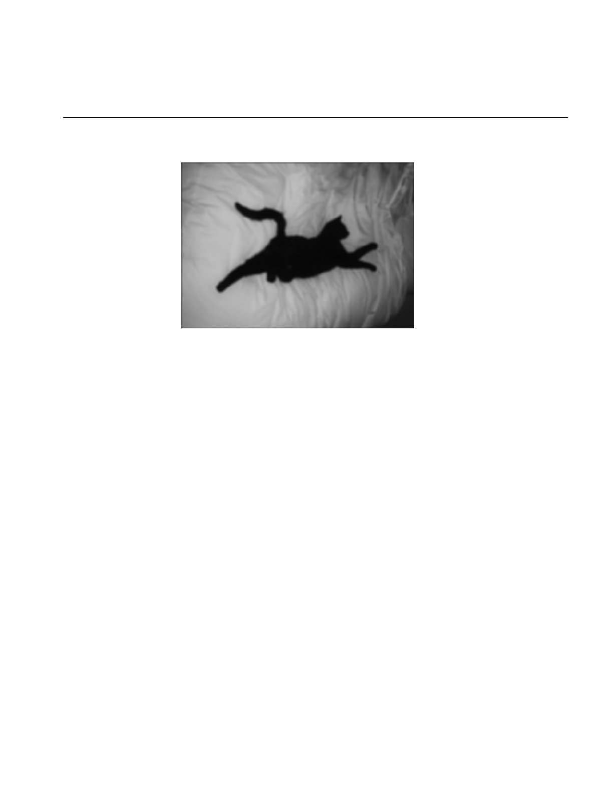
Image Processing Operators Provided with IL
111
Figure 4-16 An Image Blurred with ilBlurImg
The ilSharpenImg class is similar to ilBlurImg, except that instead of using a kernel that
blurs, it uses a kernel that sharpens the image data. Its constructor takes a similar set of
arguments:
ilSharpenImg(ilImage *img = NULL, float sharpness=.5,
float radius=1.5,ilEdgeMode e=ilPadSrc);
The sharpness factor indicates the degree of sharpening that should occur. This factor can
have a value between 0.0 and 1.0, with a default value of 0.5. A sharpened image appears
in Figure 4-17.
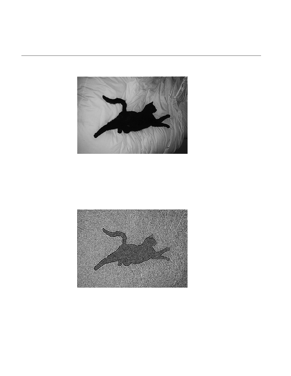
112
Chapter 4: Operating on an Image
Figure 4-17 An Image Sharpened with ilSharpenImg
As with ilBlurImg, you can dynamically change the sharpness factor (with
setSharpness()) and the size of the radius (with setSharpenRadius()). getSharpness()
and getSharpenRadius() are the query methods that return the values of the sharpness
factor and radius. Making the size of the radius too large or repeatedly cycling an image
through the sharpening operation can result in a grainy, high-contrast image. Figure 4-18
shows an example of this.
Figure 4-18 An Over-sharpened Image

Image Processing Operators Provided with IL
113
To see additional illustrations of the ilBlurImg and ilGBlurImg transformations, refer to
“Spatial Domain Transformations” on page 401.
Rank Filtering an Image
The ilRankFltImg class performs two-dimensional rank filtering, which is typically—
though not exclusively—done on black-and-white images. It involves sorting all the
pixel values (for each channel) for a neighborhood of pixels. Then, the target pixel is
assigned the values corresponding to a specified rank. For example, suppose you have
chosen a 3 x 3 neighborhood and a desired rank of 0 (the minimum). In this case, each
pixel is assigned the lowest value found among itself and its eight surrounding pixels.
The classes that derive from ilRankFltImg—ilMinFltImg, ilMaxFltImg, and
ilMedFltImg—assume that the desired rank is the minimum possible rank, the
maximum possible rank, and the median, respectively. Median filtering is useful for
removing binary, or impulse, noise in image data. Minimum and maximum rank filtering
produce morphological erosion and dilation. An example of an image processed with
ilMedFltImg appears in Figure 4-19.
The only public member function defined by these three classes is a constructor, and each
of these constructors takes the same set of arguments. ilMinFltImg’s constructor is shown
below:
ilMinFltImg(ilImage* inputImage = NULL,
ilEdgeMode edge=ilPadSrc, ilKernel* inputKernel=0);
As shown, you need to specify the input image, how pixels at the edge of the image are
to be handled, and the kernel. The kernel is treated as a mask. Only nonzero elements are
included in the neighborhood; the rest are ignored, as are the kernel weights.
The constructor for the ilRankFltImg superclass takes the same set of arguments and an
additional one for specifying the desired rank for the target pixel:
ilRankFltImg(ilImage* inputImage = NULL, int filterRank = -1,
ilEdgeMode eMode = ilPadSrc, ilKernel* inputKernel=NULL);
The default rank of minus 1 indicates that median rank should be used. You can
dynamically change the desired rank with the setRank() function. You can also
determine what the maximum possible rank is with getMaxRank().
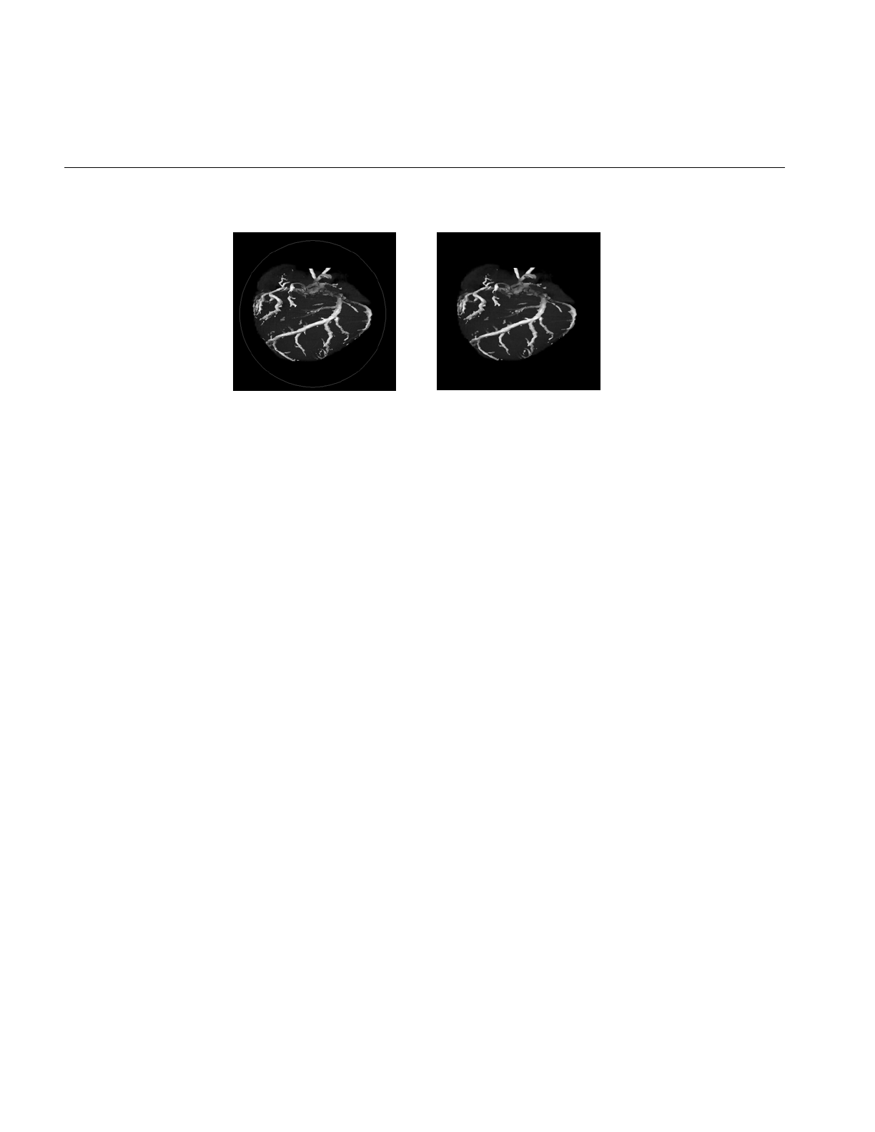
114
Chapter 4: Operating on an Image
Figure 4-19 Median Rank Filtering on an Image
To see additional illustrations of the rank filtering transformations, refer to “Spatial
Domain Transformations” on page 401.
Morphological Operators
Morphological operators include shape-dependent, nonlinear image transformations
such as erosion and dilation. The operators implemented in IL, ilDilateImg and
ilErodeImg, can be used on 1-D, 2-D or 3-D data sets. More powerful morphological
operations such as “opening” and “closing” can be performed by chaining together
dilation and erosion operations. Opening can be accomplished by an erosion followed by
a dilation. Closing can be done with a dilation followed by an erosion.
These operations are defined on binary or grayscale images. Note that you can operate
on color images if you remember that “binary” and “grayscale” indicate how the pixel
values or intensities in each channel of the image are interpreted. A binary image
contains no more than two levels or intensity values: zero and not zero. An 8-bit image
with 256 pixel intensities can be treated as a binary image by collapsing the intensities
into two groups, for example, a zero pixel intensity could be represented with a zero, and
all intensities between 1 and 255 could be represented with a nonzero value. A grayscale
image, of course, includes more than two intensity values. Thus, an 8-bit image can be
treated as an input image with 256 pixel intensities. Typically, the image has a single
channel. (For multichanneled input, the operations are performed on each channel
independently.)
Both ilErodeImg and ilDilateImg are derived from ilSpatialImg and thus involve moving
a kernel across an image, but the operation performed is not a computed sum. Instead,
in morphological operations, the kernel is called a ‘‘structuring element’’ (SE) and is
O
riginal Filtered

Image Processing Operators Provided with IL
115
represented by an ilKernel. The SE, like the input image, can be interpreted as binary or
grayscale. When applied to an image, a morphological operator returns a quantitative
measure of the image’s geometrical structure in terms of the SE.
The interpretation of the numbers that make up an SE depends on the type of
morphological operation being performed. Negative SE elements are always treated as
logical “do not cares” when the operation is in progress, image pixels under negative SE
elements are ignored. Thus, the support of the SE is limited to those elements that are
nonnegative. This permits the creation of odd-shaped SEs. The image pixel under the
origin is the one potentially modified.
Note: You can change the origin of the SE by using ilKernel’ssetOrigin() method. The
default is in the center of the SE.
The result of erosion or dilation on a binary image (regardless of whether the SE is binary
or grayscale) is to turn every pixel either “on” or “off.” A pixel in the output image can
then be assigned one of two intensities, corresponding to whether it is on or off. These
two intensities are typically the maximum and minimum values of the operator image,
which can be set using setMaxValue() and setMinValue() (inherited from ilImage). If
they are not explicitly set, the maximum and minimum values are inherited from the
input image. For the example of an 8-bit image, the minimum value might be 0 and the
maximum 255. A pixel that is 0 in the input image might have a value of 255 in the output
image, and a nonzero input pixel might be 0 in the output.
The interpretation of the image or the SE as binary or grayscale can be controlled through
the enumerated type ilMorphType, as described below.
•If the input image and the SE are binary (ilMorphType = ilBinBin), the SE is used to
perform a hit-or-miss transformation. That is, if a zero image pixel falls under a zero
SE element, or if a nonzero image pixel falls under a nonzero SE element, the image
pixel beneath the SE origin is turned on (assigned the maximum value) for dilation
and turned off (assigned the minimum value) for erosion. Typically, for binary
images, an SE is composed of negative and positive ones.
•If the input image is binary and the SE type is grayscale (ilMorphType = ilBinGray),
the nonnegative SE elements determine the support area. In other words, image
pixels under negative SE elements are ignored, but if a positive image pixel falls
under a non-negative SE element, the target pixel (under the SE origin) is turned on
for dilation or off for erosion.
•If the input image is grayscale and the SE type is binary (ilMorphType = ilGrayBin),
the maximum or minimum (depending on whether dilation or erosion is being

116
Chapter 4: Operating on an Image
performed, respectively) of image pixels falling under positive SE elements is
computed.
•If the input image and the SE are grayscale and a “set” operation is desired
(ilMorphType = ilGrayGraySet), the maximum or minimum (depending on
whether dilation or erosion is being performed) of image pixels falling under
nonnegative SE elements is computed.
•If a “function” operation is desired (ilMorphType = ilGrayGrayFct), the
computation is the same as for ilGrayGraySet, except that the SE elements are
added to the image pixels before computing the minimum or maximum.
The constructors for erosion and dilation are shown below:
ilDilateImg(ilImage* inputImage = NULL,
ilMorphType mtype = ilBinGray, ilKernel* se = NULL,
ilEdgeMode eMode = ilPadSrc);
ilErodeImg(ilImage* inputImage = NULL,
ilMorphType mtype = ilBinGray, ilKernel* se = NULL,
ilEdgeMode eMode = ilPadSrc);
Each operator accepts a pointer to an input image (inputImage), a specification of the type
of morphological operation (mtype), a structuring element (the ilKernel pointer se), and an
edge mode (eMode).
The morphological transform types, which are members of the enumerated type
ilMorphType (defined in il/iflDataTypes.h), are summarized below. These types define
whether data in the image and the structuring element (SE) is treated as binary (that is,
having a zero or a nonzero value) or as grayscale (that is, with an appropriate range for
its data type).
BinBin Dilation or erosion on a binary image with a binary SE.
BinGray Dilation or erosion of a binary image with a grayscale SE. The operation
is performed over the support of nonnegative SE elements.
GrayBin Dilation or erosion of a grayscale image with a binary SE. The operation
is performed over the positive support of the SE.
GrayGraySet Dilation or erosion of a grayscale image with a grayscale SE. The
operation is performed over the nonnegative support of the SE.
GrayGrayFct Dilation or erosion of a grayscale image with a grayscale SE. The dilation
or erosion is performed as a function operation over the nonnegative
support of the SE; that is, the SE elements are added to the image pixels
before the dilation or erosion is performed.
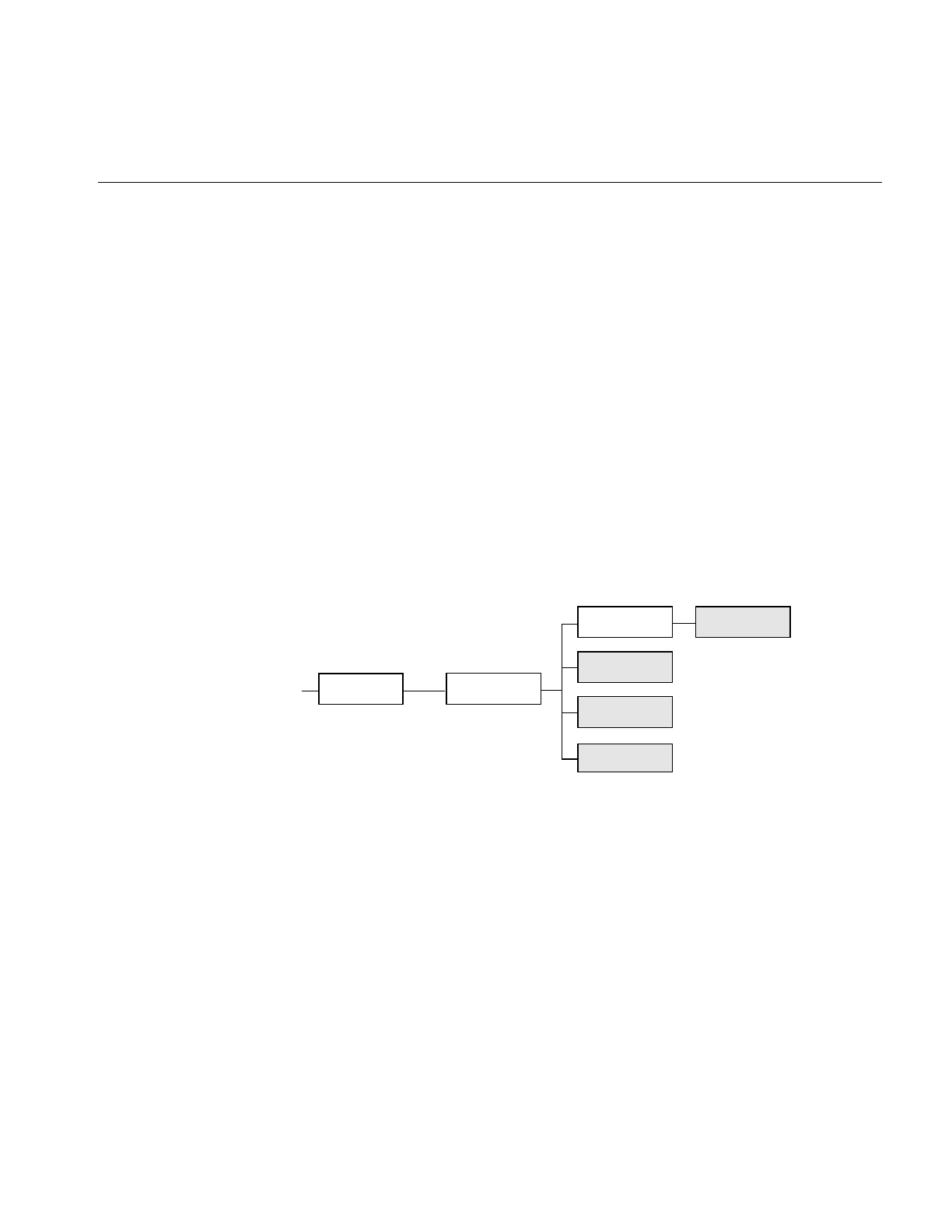
Image Processing Operators Provided with IL
117
Both ilDilateImg and ilErodeImg define these two functions:
void setMorphType(ilMorphType type);
ilMorphType getMorphType();
setMorphType() allows you to set the type of morphological operation and
getMorphType() returns the type of operation.
Edge Detection
The operators described in this section are gradient operators that produce
edge-enhanced images by performing orthogonal convolutions with particular kernels.
This section focuses on how to use these operators rather than on the specific algorithm
implemented by each of these operators. For more information about the algorithms, see
the reference pages for the specific class.
The classes described in this section inherit directly or indirectly from ilSpatialImg, as
shown in Figure 4-20.
Figure 4-20 Edge Detection Operator Inheritance Hierarchy
The constructors for the ilRobertsImg and ilSobelImg operators take the same
arguments:
ilRobertsImg(ilImage *inputImage= NULL, double biasVal = 0.,
ilEdgeMode edgeMode = ilPadSrc);
ilSobelImg(ilImage *inputImage = NULL, double biasVal = 0.,
ilEdgeMode edgeMode = ilPadSrc);
The image to be transformed is specified by inImg. The other two arguments, which have
default values, indicate a bias value to be added as each pixelwise convolution is
ilOpImg
...
ilCompassImg
ilSpatialImg
ilConvImg
ilSobelImg
ilRobertsImg
ilLaplaceImg
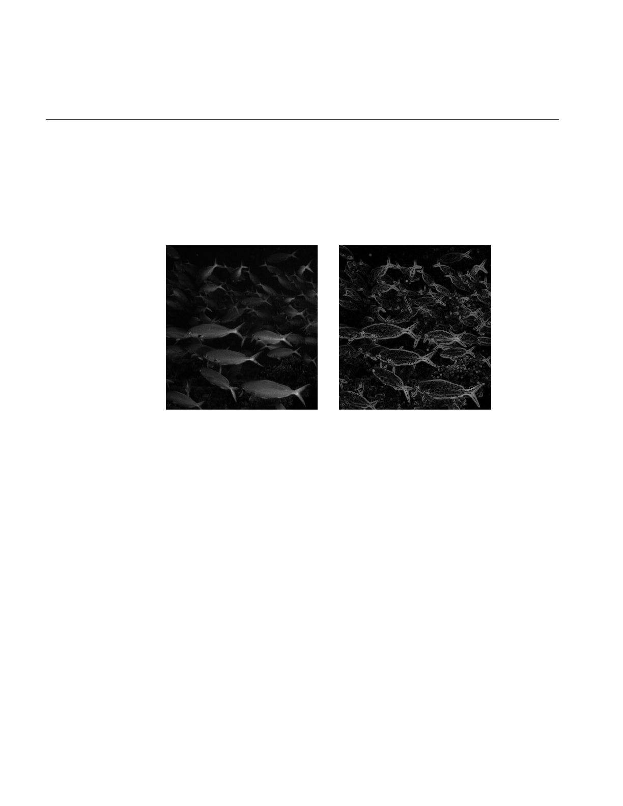
118
Chapter 4: Operating on an Image
performed and how pixels at the edge of a page are to be handled. These arguments have
the same meaning as the ones supplied in the ilConvImg constructor, which is described
in the preceding section. As explained in more detail in the reference pages, these
operators perform two orthogonal, two-dimensional convolutions, which are then
combined with predefined kernels. The resulting images are edge-enhanced images. An
example image produced by ilRobertsImg is shown in Figure 4-21.
Figure 4-21 Edge Image Produced by ilRobertsImg
The constructor for the ilLaplaceImg operator uses the same arguments as the
constructors shown above, plus an additional argument that allows you to select one of
two predefined kernels:
ilLaplaceImg(ilImage *inputImage= NULL, double biasVal = 0.,
ilEdgeMode eMode = ilPadSrc, int kerno = 1);
The kerno argument can be either 1 or 2; the corresponding kernels are listed in the
reference page for ilLaplaceImg. You can use setKernel() to specify either kernel after
you have created an ilLaplaceImg object.
A compass operator measures gradients in a specified direction. The ilCompassImg
operator allows you to specify the desired direction as an angle between 0 and 360
degrees or as one of eight compass points. You can also specify the size of the kernel to
Original Filtered

Image Processing Operators Provided with IL
119
be used. Once all this information is supplied, a square kernel is generated, which is then
convolved with the image data. Here’s the class constructor:
ilCompassImg(ilImage *inImg= NULL,
float angleDir = ilCompassN, double biasVal = 0.,
int kernSize = 3,ilEdgeMode edgeMode = ilPadSrc);
The angleDir argument can be a number or one of the following values (see Table 4-2),
which correspond to the compass points.
North, or 0 degrees, is the top of an image (as it is displayed using ilDisplay). Angles are
measured from north in a clockwise direction. The bias value and edge mode arguments
for the constructor have the same meaning as those for ilLaplaceImg. Since the kernel is
always square, only one dimension of its size needs to be specified. You can set and
retrieve the bias value with setBias() and getBias(), which are defined by ilOpImg.
Figure 4-22 shows an example image produced by using ilCompassImg.
Table 4-2 Compass Directions for the ilCompassImg Operator
Value Angle (in degrees
ilCompassN 0
ilCompassNE 45
ilCompassE 90
ilCompassSE 135
ilCompassS 180
ilCompassSW 225
ilCompassW 270
ilCompassNW 315
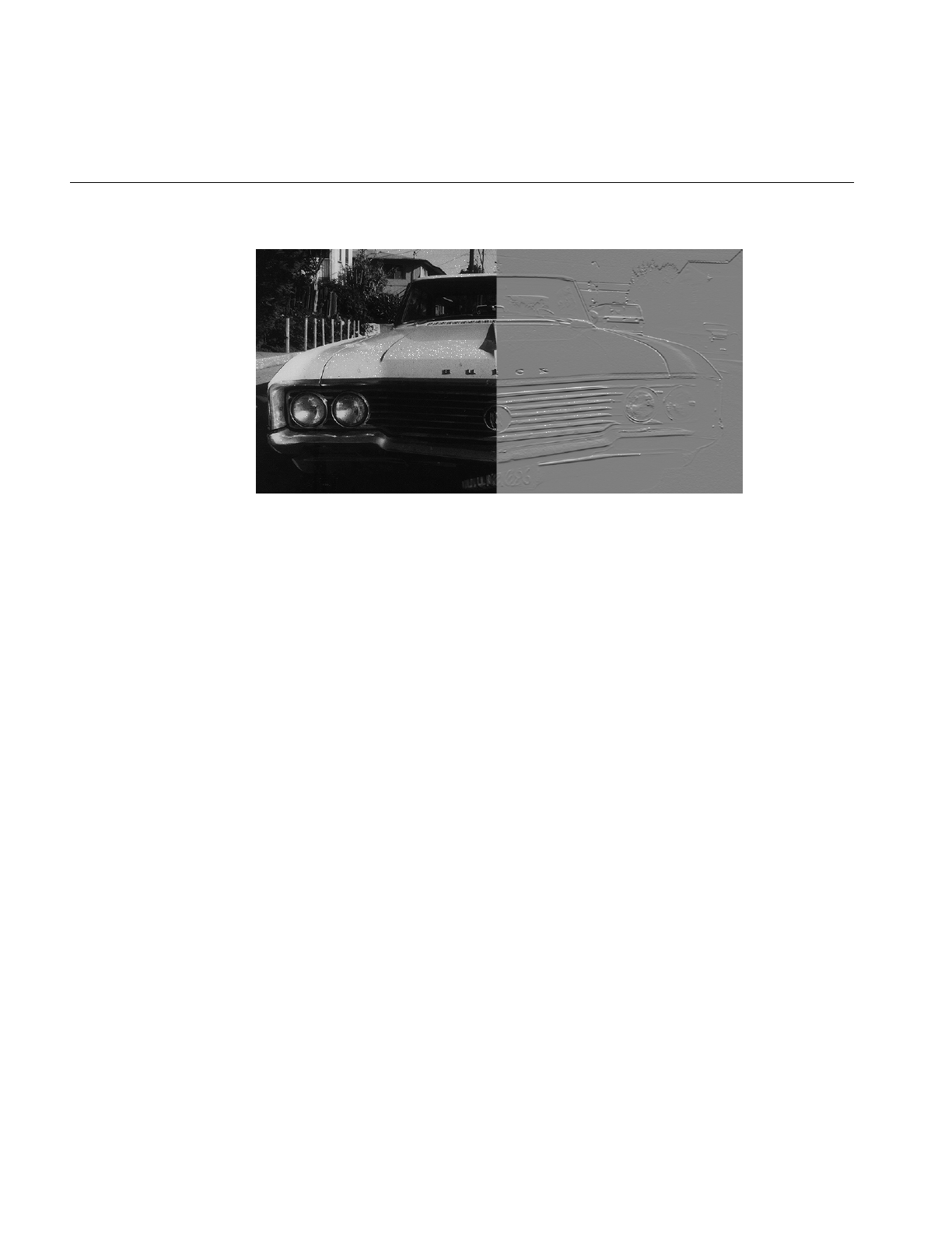
120
Chapter 4: Operating on an Image
Figure 4-22 A Compass Filtered Image
Once you have created an ilCompassImg operator, you can dynamically change the
direction of the gradient with either setAngle() or setXYWt():
void setAngle(float angleDir = ilCompassN);
void setXYWt(float Xwt = 0.0, float Ywt = 1.);
The setXYWt() function specifies weights in the x and y dimensions, which are then used
to generate the kernel. The ilCompassImg reference page describes in more detail how
the kernel is generated from the angle or weights.
You can query an ilCompassImg about its angle or weights with these functions:
float getAngle();
void getXYWt(float& Xwt, float& Ywt);
Frequency Domain Transformations
it is often convenient to manipulate data in the frequency domain, particularly when
restoring, enhancing, or removing noise from images. The ilRFFTfImg operator
described in this section performs a forward fast Fourier transform (FFT) on an image
(containing “real-valued” data, not complex). Once you have converted an image into
the frequency domain, you can use any of the numerous Fourier operators to manipulate
the image data. Then, when you are finished, you can use ilRFFTiImg, which performs
Unfiltered Filtered
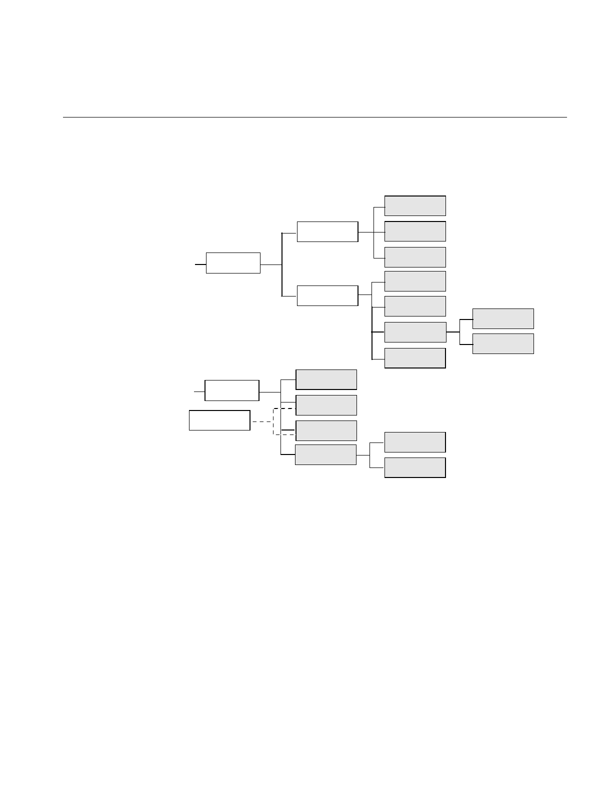
Image Processing Operators Provided with IL
121
an inverse FFT, to convert back to the spatial domain. Figure 4-23 shows the frequency
domain operators and how they fit into IL inheritance hierarchy.
Figure 4-23 Frequency Domain Operator Inheritance Hierarchy
Forward and Inverse Fourier Transforms
As shown in Figure 4-23, both ilRFFTfImg and ilRFFTiImg inherit publicly from ilOpImg
and privately from ilFFTOp. You should think of these two classes as operators that
simply use the forward and inverse transform functions defined by ilOpImg. ilRFFTiImg
tries to set the page size large enough to hold an entire channel of the image.
The FFTs are performed using the Prime Factor algorithm, using floating point
arithmetic. (For more information on the specifics of this algorithm, see the ilFFTOp
reference page and the article “Symmetric FFTs,” by Paul N. Swarztrauber, Mathematics
of Computation, Vol. 47, Number 175, July 1986, pp. 323-346.) The only restriction this
ilOpImg
...
ilFRaisePwrImg
/ilFDyadicImg
ilFConjImg
ilFMultImg
ilFCrCorrImg
ilFFTOp
ilFMonadicImg
ilFDivImg
ilFMagImg
ilFMergeImg
ilFPhaseImg
ilRFFTfImg
ilFFiltImg
ilRFFTiImg
ilFGaussFiltImg
ilFExpFiltImg
ilFPolyadicImg
...
ilFSpecImg
ilFPolarImg

122
Chapter 4: Operating on an Image
algorithm places on the input image is that it have a real (non-complex) data type other
than iflBit. However, the algorithm is most efficient if the image already contains floating
point data (so it does not have to be converted for processing and then converted back
again), has an iflSeparate order, and has dimensions that are products of small primes.
Dimensions that are a power of two yield the most efficient computation. The reference
pages for each of the Fourier operators described in this section contain more
information about the methods used to perform the computations as well as hints about
how to achieve the greatest possible efficiency.
The constructor for the ilRFFTfImg operator and the member function, ilFFTOp.ilRfft(),
perform a forward FFT.
ilRFFTfImg(ilImage *img = NULL, short option = ilFFTxform2D);
ilStatus ilRfftf(ilImage* src, int srcCh, void* dst,
short opt = ilFFTxform2D, ilMpCacheRequest* req = NULL);
Using the ilRFFTfImg operator to perform a forward FFT is relatively easy. The first
argument is a pointer to the source image that is to be transformed. The second
argument, called option, allows you to choose whether a one- or two-dimensional
transform is performed; if it is:
•1, a one-dimensional FFT is performed on the rows of data
•2, a one-dimensional FFT is performed on the columns of data
•3, a two-dimensional FFT is performed (the default)
You can dynamically change this parameter with the setOption() function.The first four
arguments to ilRFFTfImg() function specify which channel of the source image is to be
transformed and into which channel of the destination image the result should be put. In
this example, channel 0 of srcImg is transformed and placed into channel 0 of destImg. The
size of both of these images must be the same. The last argument for this function
specifies which of the three options described above is desired. (It has the same meaning
as the second argument to the ilRFFTfImg constructor.)
Since the source image must contain real data (not complex numbers), the output is
conjugate-symmetric. In other words, only two of the four quadrants are unique, and
only these are computed for the output. The output is complex, however, so both the real
and imaginary results must be reported. Because of this, the destination image has the

Image Processing Operators Provided with IL
123
same x and y dimensions as the source image. Table 4-3 shows the format of the output
from the ilRFFTfImg operator function. (The origin is in the upper left corner.)
Columns 1 through nx-2 contain the real and imaginary components of a complex
transform, for example, column 1 contains the real component and column 2 the
corresponding imaginary component of the first complex FFT output. The column 0
represents the 0-frequency (or DC) component, and column nx-1 represents the highest
(Nyquist) frequency along the x-direction. These two columns resemble the output of a
real-valued FFT. In the example shown, both nx and ny are assumed to be even. If nx were
odd, the Nyquist column would be missing. If ny were odd, the last row shown would
be missing. Table 4-4 shows the output format if both nx and ny are odd.
Table 4-3 Output of a Forward Fourier Transform (if nx and ny are even)
01234 ...nx-3 nx-2 nx-1
0 real real imag real imag ... real imag real
1 real real imag real imag ... real imag real
2 imag real imag real imag ... real imag imag
3 real real imag real imag ... real imag real
4 imag real imag real imag ... real imag imag
... ... ... ... ... ... ... ... ... ...
ny-3 real real imag real imag ... real imag real
ny-2 imag real imag real imag ... real imag imag
ny-1 real real imag real imag ... real imag real
Table 4-4 Output of a Forward Fourier Transform (if nx and ny are odd)
01234 ...nx-2 nx-1
0 real real imag real imag ... real imag
1 real real imag real imag ... real imag
2 imag real imag real imag ... real imag
3 real real imag real imag ... real imag
4 imag real imag real imag ... real imag

124
Chapter 4: Operating on an Image
This format is what is expected as input by all the Fourier operators described in this
section. In particular, the constructor for the ilRFFTiImg operator expects this format in
their source image. They perform an inverse FFT, which is to say they convert the input
Fourier data back to the spatial domain:
ilRFFTfImg(ilImage *img = NULL, short option = ilFFTxform2D);
ilStatus ilRfftf(ilImage* src, int srcCh, void* dst,
short opt = ilFFTxform2D, ilMpCacheRequest* req = NULL);
The ilRFFTiImg constructor takes a pointer to the source image and the same option
argument described above. (The ilRFFTiImg operator also defines the same setOption()
function described above.) For the ilRFFTiImg() function, the source and destination
images (src and dst) must be the same size; the srcCh and dstCh arguments specify the
channel to be transformed and the destination channel number. Both the constructor and
the function produce output data that is real. The output of the forward transform is
multiplied by 1.0/(nx*ny) so that the forward transform followed by the inverse returns
the original image unscaled.
Separating the Magnitude and Phase Components
The operators described in this section allow you to separate the magnitude and phase
components of a complex Fourier image so that you can process or filter them
independently and then combine them into a complete image when you are finished.
Such an operator chain would look like Figure 4-24.
... ... ... ... ... ... ... ... ...
ny-2 real real imag real imag ... real imag
ny-1 imag real imag real imag ... real imag
Table 4-4 (continued) Output of a Forward Fourier Transform (if nx and ny are odd)
01234 ...nx-2 nx-1
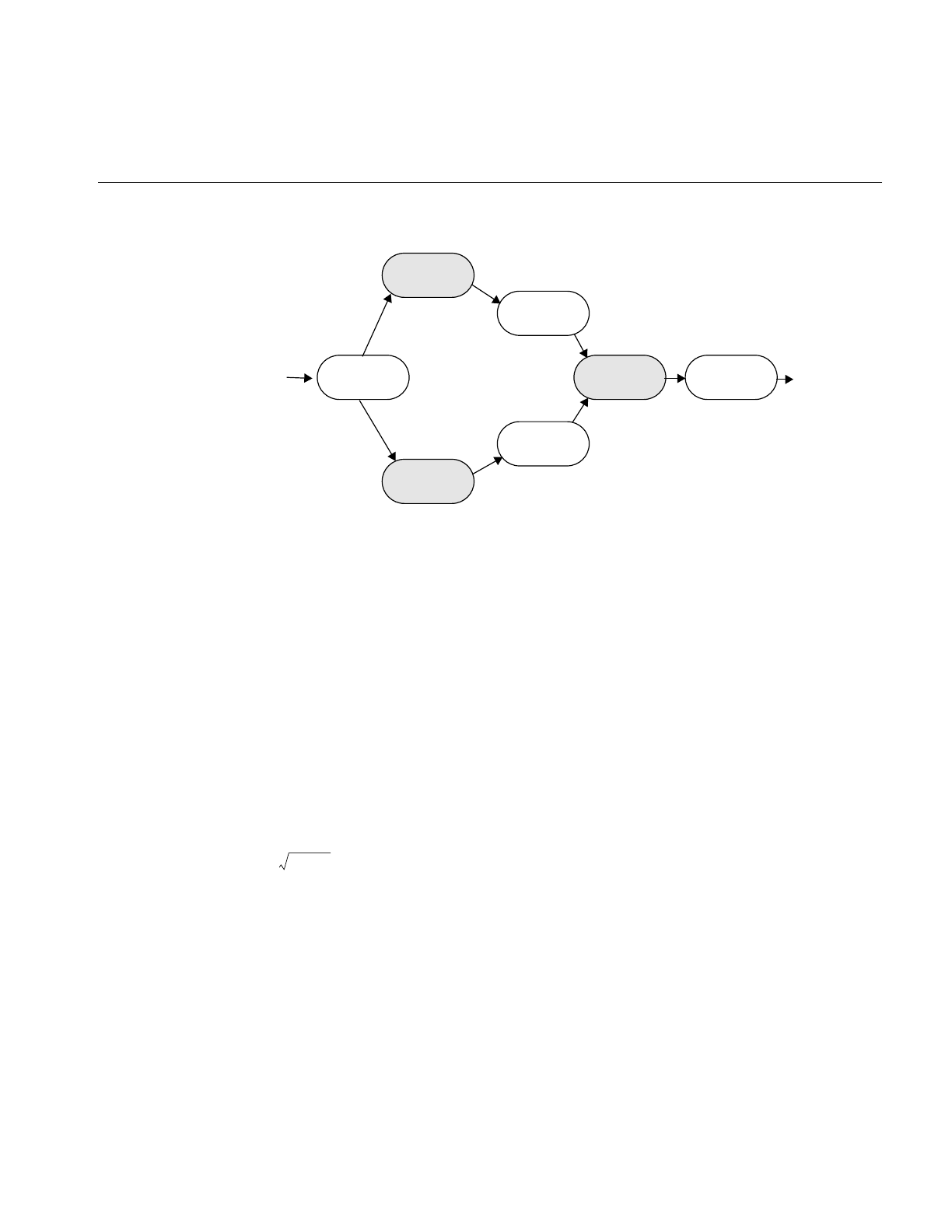
Image Processing Operators Provided with IL
125
Figure 4-24 Magnitude and Phase Fourier Operators
As you might expect from their names, the ilFMagImg operator computes the magnitude
of an input complex Fourier image, and ilFPhaseImg determines the phase component.
The constructors for both of these operators expect the format produced by ilRFFTfImg
(which is described above):
ilFMagImg(ilImage *img = NULL);
ilFPhaseImg(ilImage *img = NULL);
The x -dimension of the output image for both these operators is half of the input image’s
size, plus one; the y dimension is unchanged. The x dimension shrinks because the input
image uses two columns for each Fourier element, one for the real component and one
for the imaginary, whereas the magnitude and phase are not complex. For a complex
number represented by a+ ib,
the magnitude is
and the phase is
atan (b/a)
An operator that is similar to ilFMagImg, ilFSpectImg, computes the spectrum of a
Fourier image. The computation is the same as that performed by ilFMagImg, but all
ilFMagImg
ilRFFTfImg ilRFFTiImg
(operators)
ilFPhaseImg
ilFMergeImg
(operators)
a2b2
+

126
Chapter 4: Operating on an Image
quadrants are represented in the output image, not just the two that are unique. As a
result, the size of the output image is the same as that of the input image, and the origin
of the output image is at its center rather than its upper left corner. You might use an
ilFSpectImg object for displaying, although you probably want to scale the spectral
values using ilHistScaleImg. (This operator is described in “Radiometric
Transformations” on page 136.) An ilFMagImg object is more efficient for processing
since redundant calculations are not performed.
The constructor for ilFSpectImg simply takes a pointer to the source image:
ilFSpectImg(ilImage *img= NULL);
The ilFMergeImg operator merges an ilFMagImg and an ilFPhaseImg to produce the
original whole Fourier image. The merged image is converted from polar to rectangular
form so that it is in the format expected by ilRFFTiImg. The constructor for ilFMergeImg
takes pointers to the two images and an int that specifies the desired x dimension of the
final image:
ilFMergeImg(ilImage *mag, ilImage *ph, int xsize);
The xsize argument is required because the x dimension of a merged image can’t be
uniquely determined from the x dimension of mag or phase. For example, if mag and phase
have x dimensions of 129, the merged image could have an x dimension of either 256 or
257. You can explicitly set the x dimension with setXsize().
Filtering
Two filter operators are provided for use on Fourier images: ilFExpFiltImg and
ilFGaussFiltImg. These operators derive from ilFFiltImg, an abstract class that
implements the basic support for frequency domain filtering. (You can derive your own
filter as described in “Deriving From ilFFiltImg” on page 241.) Both ilFExpFiltImg and
ilFGaussFiltImg expect input in the format produced by ilRFFTfImg. Typically, you’ll
apply the ilRFFTiImg operator to the filtered image in order to view the results in the
spatial domain.
The constructors for these operators are shown below:
ilFExpFiltImg(ilImage *img, float alpha, float beta,
float gamma,float eccent, float theta);
ilFGaussFiltImg(ilImage *img, float hfgain, float dcgain,
float minhalf, float majhalf, float theta);

Image Processing Operators Provided with IL
127
For more information about what these arguments mean, see the filter equations below
and the reference pages for these two operators.
This is the filtering equation used by ilFExpFiltImg:
This is the filtering equation used by ilFGaussFiltImg:
where for both equations:
H() = transfer function of the filter
u,v = two-dimensional frequency coordinates
,, ,
, where = angle in degrees of the filter’s orientation
xSize = x dimension of the source image
ySize = y dimension of the source image
and where for ilFExpFiltImg:
α = high-frequency asymptote
β = decay coefficient
γ = exponential decay coefficient
σs= 1.0 and
where ε = eccentricity of equal contours of
the filter and where for ilFGaussFiltImg:
hf = gain of filter at the Nyquist (highest) frequency
Huv,()αβeγa11 ua
12v+()
2a21ua
22v+()
2
+[]{
+=
Huv,()hf dc hf–()ea11ua
12v+()
2a21ua
22v+()
2
+{}–
+=
a11
σSθ'cos
xSize
--------------------
=a12
σSθ'sin
ySize
-------------------
=a21
σLθ'sin
xSize
-------------------
–= a22
σLθ'cos
ySize
--------------------
=
θ'πθ
180
---------
=θ
σL
1
1ε2
–
------------------
=

128
Chapter 4: Operating on an Image
dc = gain of filter at zero frequency
and
minHalf = frequency of half-power point along the minor elliptical axis
majHalf = frequency of half-power point along the major elliptical axis
Table 4-5 shows two examples of specific values that might be passed in for
ilFGaussFiltImg.
The high-pass values create a two-dimensional circular high-pass filter with a cutoff
value of 0.01 on both axes; its DC gain is 0.004, and its gain at the highest frequency is 3.0.
A high-pass filter diminishes the constant or slowly-changing portions of an image and
thereby accentuates the edge portions (creating a high-contrast, edge image). The
low-pass values create a two-dimensional circular low-pass filter with a cutoff value of
0.05 on both axes; its DC gain is 1.0, and its gain at the highest frequency is 0.002. A
low-pass filter diminishes the dramatically changing values at edges in an image and
thereby accentuates the constant or slowly varying portions (creating a blurry image).
See Figure 4-25 and Figure 4-26.
Table 4-5 Sample Parameter Values for ilFGaussFiltImg
Parameter High-pass Low-pass
dc 0.004 1.0
hf 3.0 0.002
minHalf 0.01 0.05
majHalf 0.01 0.05
0.0 0.0
σS
0.693147
minHalf2
------------------------=σL
0.693147
majHalf2
------------------------=
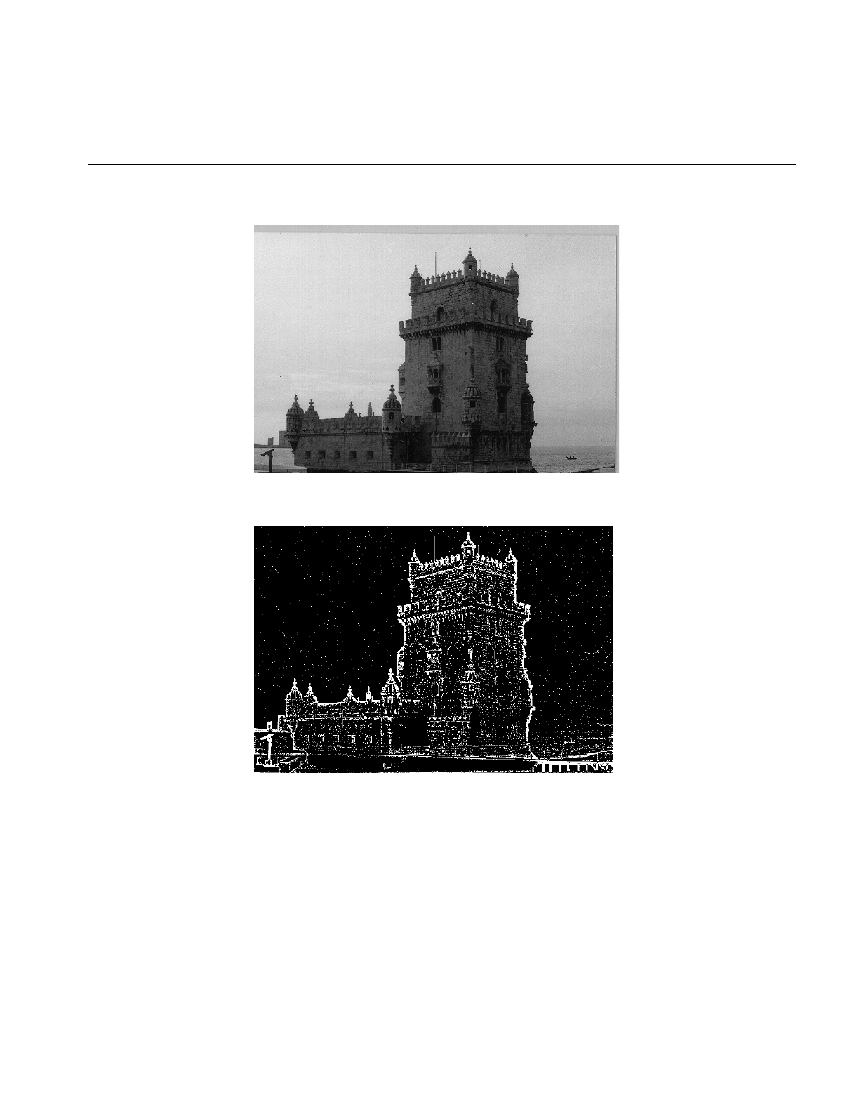
Image Processing Operators Provided with IL
129
Figure 4-25 Original Image
Figure 4-26 Image Processed with ilFGaussFiltImg
Functions are defined in ilFExpFiltImg.h and ilFGaussFiltImg.h to set the value of all the
parameters used in the constructors for both operators.

130
Chapter 4: Operating on an Image
In ilFExpFiltImg.h:
void setAlpha(float val);
void setBeta(float val);
void setGamma(float val);
void setEccent(float val);
void setTheta(float val);
In ilFGaussFiltImg.h:
void setHFgain(float val);
void setDCgain(float val);
void setMinHalf(float val);
void setMajHalf(float val);
void setTheta(float val);
See the reference pages for more information about these functions.
Single-input Operators
The two operators described in this section are ilFConjImg and ilFRaisePwrImg, both of
which derive from ilFMonadicImg. (See “Deriving From ilFMonadicImg or
ilFDyadicImg” on page 238 for more information about deriving your own operator
from this class.) ilFConjImg and ilFRaisePwrImg expect a source image in the format
produced by ilRFFTfImg. Typically, you’ll need to convert ilFRaisePwrImg’s output to
the spatial domain by using ilRFFTiImg. (You do not typically need to convert the result
of applying ilFConjImg to an image back to the spatial domain; usually, it is used in the
middle of a chain of operators in the frequency domain.)
As its name suggests, ilFConjImg computes the complex conjugate of an image; it also
multiplies the complex values by a real factor:
ilFConjImg(ilImage *img=NULL, float scale = 1.0);
The scale argument is used to multiply or scale the values; the default value of 1.0 results
in no scaling. You can change the scaling factor with setScale(). ilFConjImg is useful in
computing the magnitude squared of the Fourier transform. For example, assume theImg
is a pointer to a valid ilImage in the spatial domain:
ilRFFTfImg forwardImg(theImg);
ilFConjImg conjugateImg(&forwardImg);
ilFMultImg magSquaredImg(&forwardImg, &conjugateImg);
You can then display magSquaredImg.

Image Processing Operators Provided with IL
131
The ilFRaisePwrImg operator raises the natural log of the magnitude values of a Fourier
image by a power, exponentiates the result, and writes the values back in complex
rectangular form:
= magnitude and p = specified power
This root-filtering operation is useful for image sharpening. The constructor for this class
is shown below:
ilFRaisePwrImg(ilImage* src, float power);
The log of the magnitude values of the source image, src, are raised by power,
exponentiated, and converted back to complex rectangular form. The valid range for
power is 0.0-1.0. You can set this value dynamically with setPower().
Dual-input Operators
Three operators take two Fourier images as inputs:
•ilFCrCorrImg, which computes the cross-correlation of two images
•ilFMultImg, which multiplies two images
•ilFDivImg, which divides two images
These classes derive from ilFDyadicImg, which implements the basic support for
dual-input Fourier operators, and they expect input images in the format produced by
ilRFFTfImg. To convert the processed data back to the spatial domain, you need to apply
the inverse transform implemented by ilRFFTiImg. See “Deriving From ilMonadicImg or
ilPolyadicImg” on page 228 for more information about deriving your own dual-input
Fourier operator.
The constructors for ilFCrCorrImg, ilFMultImg, and ilFDivImg expect two images,
which must be the same size:
ilFCrCorrImg(ilImage *img1 = NULL, ilImage *img2 = NULL);
ilFMultImg(ilImage *img1 = NULL, ilImage *img2 = NULL);
ilFDivImg(ilImage *img1 = NULL, ilImage *img2 = NULL,
int ckDiv = 1);
To compute the cross-correlation, ilFCrCorrImg multiplies src1 by the conjugate of src2
and then normalizes the result using the DC (or (0,0)) coefficient of src1. One of the
principal applications of cross-correlation in image processing is in prototype matching,
where one tries to match a given unknown image to a known image. The closest match
eln m()
pwhere m

132
Chapter 4: Operating on an Image
can be found by selecting the image that yields the correlation function with the largest
value.
Multiplying two Fourier images is equivalent to convolving them in the spatial domain.
Since the Fourier algorithm is very efficient, you might want to choose ilFMultImg over
one of ilConvImg’s subclasses if you are using a large kernel for the convolution.
ilFDivImg divides src1 by src2 and, by default, checks for division by zero according to
the following rules:
•If the numerator of the real or imaginary part is positive and the denominator is
zero, the result is the largest possible floating point value (3.40282346e+38).
•If the numerator of the real or imaginary part is negative and the denominator is
zero, the result is the smallest possible floating point value (-3.40282346e+38).
•If both the numerator and the denominator are zero, the result is zero.
You can call setCheck() and pass in a 0 to prevent ilFDivImg from checking for division
by zero.
You can use ilFDivImg in image restoration. Given the Fourier transform of a degraded
or noisy image and the Fourier transform of the noise function (or “noise image”), you
can retrieve a clean image by dividing (in the frequency domain) the degraded image by
the noise image. Once converted back to the spatial domain, you can then display the
clean image.
Generation of Statistical Data
it is often desirable to collect statistical information about an image, such as how
frequently various pixel values occur and what the minimum and maximum pixel values
are. The ilImgStat class computes this kind of information for an entire image or for a
specified region within an image. More specifically, for each channel of image data, it
computes:
•a one-dimensional histogram showing frequency of pixel values
•the minimum and maximum pixel values
•the mean and standard deviation of the data, calculated from the histogram
The ilImgStat class inherits from ilLink, as shown in Figure 4-27.

Image Processing Operators Provided with IL
133
Figure 4-27 The ilImgStat Inheritance
ilImgStat does not derive from ilImage, so its constructor does not create an ilImage. It
derives from ilLink. Thus, an ilImgStat object cannot be passed as an image to another
operator, but it might be one of an operator’s input arguments.
Multiprocessing on an ilImgStat object can turned on or off and queried using the
enableMP() and isMPenabled() functions.
ilImgStat has two parents: the input image from which the data is derived, and the ROI,
if any. If either of these objects is altered, the two ilLink inheritance mechanism ensures
that the ilImgStat object reconfigures itself.
Calculation of the statistics is deferred until it is triggered by one of the get...() methods.
If only the minimum-maximum is requested, a histogram is not computed. For any other
get...() method, the histogram is computed. If the data order is separate, on the minimal
subset of the channels is analyzed. The analysis results (minimum, maximum, historicity,
mean, standard deviation, are cached in the ilImgStat to avoid recalculation. If the object
is altered either directly or indirectly with inheritance, the cached data id discarded.
Note: There is an “auto calc” flag that modifies this default behavior. For more
information, see the ilImgStat man page.
The constructor for the ilImgStat class allows you to specify whether the data should be
computed for the entire source image or for just a portion of it, as shown in the next code
fragment. The portion is defined as a region of interest (ROI); see “Defining a Region of
Interest” on page 153 for more information about the ilRoi class, which defines an ROI
within an image.
ilImgStat(ilImage* img=NULL, ilRoi* roi=NULL,
int xoffset=0, int yoffset=0, int zoffset=-1, nz=0);
The xoffset, yoffset, and zoffset parameters represent the offsets into the input image, img,
at which the ROI is placed. The z argument specifies the starting z value, and nz indicates
the size of the z tile. Thus, you can use these values to effectively create a 3-D ROI. The
coordinates of the roi image are specified in the coordinate space of the input image.
You can also specify an ilRoi and its offsets for the ilImgStat with the following setRoi()
functions:
ilLink ilImgStat

134
Chapter 4: Operating on an Image
ilImgStat::setROI(ilRoi* roi, int xoffset=0, int yoffset=0);
ilImgStat::setZ(int z, int nz=1);
If no ROI is specified, ilImgStat performs its computations over the whole image.
ilImgStat::clearZ() unsets the tile in the Z dimension.
An Image’s Histogram
An image’s histogram, which is computed for each channel of image data, is defined by:
•the starting and ending pixel values—these establish the endpoints of the
histogram’s range.
•the number of bins—the range is evenly divided into a specified number of bins.
•the size of each bin—the size is the range covered by each bin; this is computed by
dividing the total range by the number of bins.
You use the following methods to determine the number of bins, the bin size, and the
lower limit of the first bin for any particular channel:
double lowerLimit = myImgStat.getStart(1);
double upperLimit = myImgStat.getEnd(1);
double binSize = myImgStat.getBinSize(1);
int binCount = myImgStat.getBinCount(1)
The argument for these functions is an int that specifies the desired channel.
Once you have created an ilImgStat object, you can specify the limits of a histogram using
the following methods:
void setInput(ilImage* in)
void setLimits(double start, double end);
void setBinCount(int count);
where in is the image associated with the histogram, start and end specify the lower and
upper endpoints of the range of pixel values, and count is the number of bins in which
pixel values are collected. The maximum number of bins allowed is 4096.
To access the histogram of the source image’s pixel values, use the getHist() function:
unsigned long* getHist(int chan=0);
where chan is the color channel.

Image Processing Operators Provided with IL
135
The getHist() function returns a pointer to an array that is allocated by ilImgStat. The
values in the array correspond to the number of pixels that have values within each bin’s
respective range. To represent a probability distribution, copy the long array into a float
array, and then divide each element of the array by the total number of pixels used to
compute the histogram for that particular channel. You can obtain the number of pixels
used with getTotal():
long totalPixelCount = myImgStat.getTotal(1);
The argument for this function is an int that specifies the desired channel. (The number
of pixels used for each of the channels might vary if you have specified different
endpoints for the different channels.)
If the image’s pixel ordering is iflSeparate, you can make multiple calls to getHist() for
each channel and specify varying numbers of bins and starting points and endpoints.
However, the histograms for all channels of iflInterleaved or iflSequential images are
computed on the first call to getHist(), so the number of bins and the starting points and
endpoints are fixed for subsequent calls. If you need to change the histogram’s attributes
for subsequent calls, use reset(). This function deallocates the array created with
getHist() and enables you to start over. (In general, you should call reset() or the
ilImgStat destructor as soon as you are finished with a histogram to minimize memory
usage.) If you need a histogram you have already computed, copy it into your own buffer
before calling reset().
Minimum, Maximum, Mean, and Standard deviation
The ilImgStat class defines functions that return the minimum value, maximum value,
mean, and standard deviation of a particular channel:
double getMin(int c=0);
double getMax(int c=0);
double getMean(int c=0);
double getStdDev(int c=0);
These functions all return the desired number as a double, regardless of the data type of
the image.
Other Functions
Two other support functions are provided:
void setHwEnable(ilHwAccelEnable enable);
ilHwAccelEnable getHwEnable();

136
Chapter 4: Operating on an Image
void qCalcStats(ilMpNode* parent, ilMpManager** pMgr=NULL);
You can use the first function shown above to enable and disable hardware acceleration
by passing in TRUE or FALSE, respectively. You can use getHwEnable() to determine
whether or not acceleration is enabled.
The last function allows your application to calculate a histogram asynchronously.
Radiometric Transformations
This section describes a set of operators that adjust all the pixels of an image so that
together they have certain specified characteristics. Three of the operators described in
this section—ilHistNormImg, ilHistEqImg, and ilHistScaleImg—modify an image’s
pixel values channel by channel, so that the image’s histogram has certain desired
properties. You can limit the area for which statistics are computed by specifying an ROI
and its offsets when you create these operators; the operators then adjust all the pixels of
the image so that the entire image’s histogram matches that computed for the ROI. (See
“Defining a Region of Interest” on page 153 for more information about ROIs.) If you
have already created an image’s histogram using ilImgStat as described in the previous
section, you can pass a pointer to the existing ilImgStat object to speed the
transformations performed by these operators.
The following radiometric operators are described in this section:
ilScaleImg linearly scales the pixel data of an image so that it falls in a
new specified range
ilHistNormImg transforms an image so that its histogram is normalized
(Gaussian) and so that it has a specified mean and standard
deviation
ilHistEqImg transforms an image so that its pixel values are uniformly
distributed (so that the cumulative histogram is linear)
ilHistScaleImg clamps values to a specified percentage distribution of the
high- and low-intensity pixels and scales the remaining data
between the clamp values
ilThreshImg sets each pixel to the image’s minimum or maximum value,
depending on whether the pixel is less than or greater than a
specified threshold value
ilLutImg transforms a source image using a specified lookup table
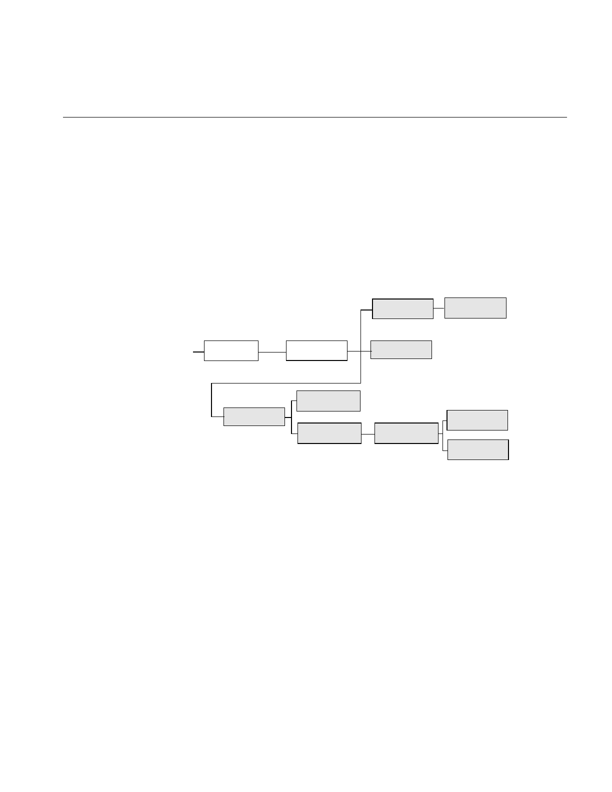
Image Processing Operators Provided with IL
137
The operators that perform radiometric scaling, ilScaleImg and ilHistScaleImg, are
accelerated on certain hardware platforms. The ilLutImg operator and the operators
derived from it, such as ilPiecewiseImg, ilHistNormImg and ilHistEqImg, are also
accelerated provided they meet the constraints specified in “Using Hardware
Acceleration” on page 253. The ilThreshImg operator is also accelerated through the LUT
mechanism, even though it is not derived from ilLutImg. All these classes derive directly
or indirectly from ilMonadicImg, as shown in Figure 4-28.
Figure 4-28 Radiometric Operator Inheritance Hierarchy
Scaling an Image
The ilScaleImg operator linearly scales the pixel data of an image so that it falls in a
specified range. If you do not know the range of the input pixels, the first constructor
shown below must be used. This constructor uses the minimum and maximum value
fields of the input image to determine the input range, and it assumes an output range of
0 to 255. If you want to override the range of the input pixel data, you can use the second
constructor and also specify an output range. The default is 0 to 255.
ilScaleImg(ilImage* img = NULL);
ilScaleImg(ilImage* img, double inMin, double inMax,
double outMin=0, double outMax=255.999);
ilPiecewiseImg transforms a source image using a lookup table created with
a piecewise linear mapping function
ilOpImg
... ilMonadicImg
ilHistNormImg
ilThreshImg
ilHistScaleImg
ilHistEqImg
ilLutImg
ilScaleImg
ilPiecewiseImg
ilHistLutImgilArithLutImg

138
Chapter 4: Operating on an Image
Pixels of value inMin are scaled to outMin, while those of value inMax are scaled to
outMax. Pixels channel values lying between these extremes are scaled accordingly.
Pixels outside the input domain are clamped between outMin and outMax.
The scaling function is normally computed based on inMin and inMax (the domain) and
outMin and outMax (the range). To do this scaling, ilScaleImg computes the slope and
intercept of a linear function of the form:
Thus, an input pixel of value x becomes an output pixel of value f(x). The slope and
intercept are computed as follows:
You can alter the operator’s parameters with these member functions:
void setRange(double outMin, double outMax);
void setDomain(double inMin, double inMax);
You can control the scaling behavior with these functions:
void resetDomain();
void resetRange();
void resetScaling();
void setScaling(double slope, double intercept);
resetDomain() invalidates the current input levels and, if none are specified using
setDomain(), the minimum and maximum values of the input images are used for the
domain.
resetRange() invalidates the current output levels and, if none are specified using
setRange(), default values are computed using the input domain and the scaling values
(slope and intercept). An example image produced using ilScaleImg is shown in
Figure 4-29.
resetScaling() forces the operator to forget any values explicitly set for slope and intercept
and to compute them as shown above.
setScaling() allows you to explicitly set the values of the slope and intercept of the scaling
function.
f
x() x slope⋅()intercept+=
slope outMax outMin–()
inMax inMin–()
------------------------------------------------------
=
intercept outMin slope inMin⋅()–=
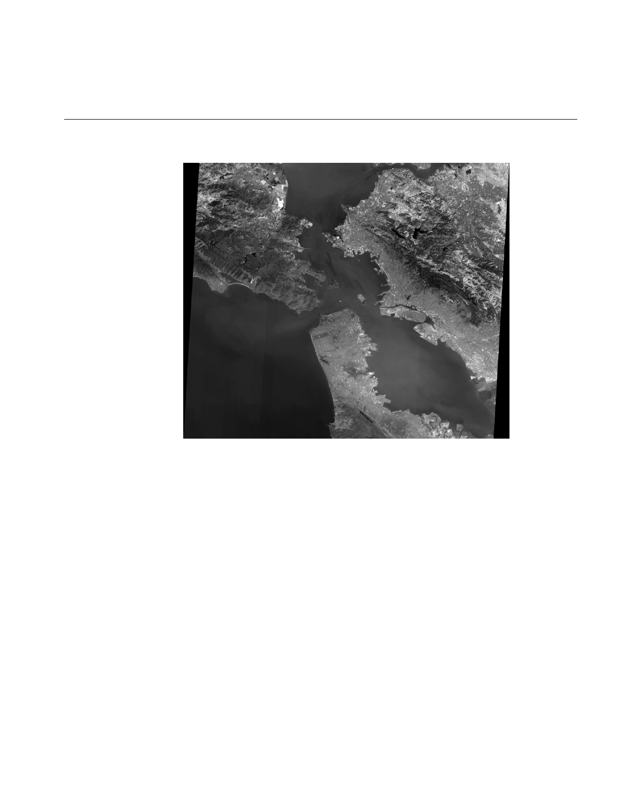
Image Processing Operators Provided with IL
139
Figure 4-29 Using Scaling
Histogram Operators
Both ilHistNormImg and ilHistEqImg derive from ilHistLutImg, which itself derives
from ilArithLutImg. This inheritance allows the histogram operators to use lookup tables
to determine resulting values, rather than perform the computations on a per-pixel basis.
As a result, the histogram operators are more efficient.
The constructors for ilHistNormImg are:
ilHistNormImg(ilImage *img, iflPixel &mn, iflPixel &std,
ilImgStat *imgstat = NULL, ilRoi *Roi = NULL,
int xoffset = 0, int yoffset = 0, int zoffset = 0);
ilHistNormImg(ilImage *img=NULL, ilImgStat *imgstat=NULL,
ilRoi *Roi=NULL, int xoffset=0, int yoffset=0,
int zoffset=0);

140
Chapter 4: Operating on an Image
The first constructor allows you to specify the source image and the desired mean, mn.
and standard deviation, std. The second constructor takes a source image and computes
default values for the mean and standard deviation. The mean for each channel is
computed as the average of the minimum and maximum values of the source image for
that channel. The standard deviation is set to 1.0 for each channel.
The iflPixels can use any data type, but their number of channels must match that of the
source image. If you have already created an ilImgStat object (for the source or even a
different image), you can pass a pointer to it. This makes ilHistNormImg more efficient.
If you supply both an ilImgStat and an ilRoi, the histogram computed for the ilImgStat
is used and the ilRoi is ignored.
You can dynamically change the mean, the standard deviation, the ilImgStat object, and
the ilRoi and its offsets with the following ilHistNormImg.h functions:
void setMean(iflPixel& mean);
void setStdev(iflPixel& stdev);
void setImgStat(ilImgStat* imgstat);
void setRoi(ilRoi* Roi, int xoffset = 0, int yoffset = 0);
The setImgStat() and setRoi() functions are inherited from ilHistLutImg.
Histogram equalization and histogram scaling of an image are often performed to
enhance the contrast of an image. Histogram equalization results in an image with pixel
values that are more evenly distributed.
The constructor for ilHistEqImg is shown below:
ilHistEqImg(ilImage *img = NULL, ilImgStat *imgstat = NULL,
ilRoi *Roi = NULL, int xoffset=0, int yoffset=0,
int zoffset=0);
As shown, you specify the source image, the ilImgStat object if one exists, and an optional
ROI along with its offsets. This class also inherits setImgStat() and setRoi() functions as
does ilHistNormImg.
The constructor for ilHistScaleImg is more complicated:
ilHistScaleImg(ilImage* img = NULL, double lowClip=0,
double highClip=0, double outMin=0, double outMax=255,
ilImgStat* imgstat=NULL, ilRoi* Roi=NULL,
int xoffset = 0, int yoffset = 0);

Image Processing Operators Provided with IL
141
The src argument specifies the source image. The next four arguments specify how the
source image should be transformed. The highClip and lowClip arguments indicate what
percentage of the high and low intensity pixels should be clamped to the values specified
by outMax and outMin, respectively. Imagine that the pixels are sorted in order of
increasing intensity, as in a histogram. Then, highClip percent of the highest-intensity
pixels are set to the outMax value, and lowClip percent of the lowest-intensity pixels are
set to the outMin value. After the desired pixels have been clipped, the remaining pixels
are scaled linearly between the clamp values. The optional ilImgStat and ilRoi objects
(and offsets) each have the same meaning as with ilHistNormImg.
You can dynamically change all these arguments with the following ilHistScaleImg
functions:
void setImgStat(ilImgStat* imgstat);
void setRoi(ilRoi* Roi, int xoffset = 0, int yoffset = 0);
void setClip(double lowClip, double highClip);
void setRange(double outMin, double outMax);
One other useful function, setHistLimits(), allows you to change the limits between
which the histogram is to be computed:
void setHistLimits(double low, double high);
The two arguments, low and high, define the histogram’s limits.
Be careful when changing the input to any of the histogram operators by using
setInput(). (See “Dynamically Reconfiguring a Chain” on page 57 for more information.)
If an ilImgStat has already been specified in a histogram operator constructor and then
setInput() is called, the old ilImgStat is used unless you call setImgStat() with a new one.
You can use NULL in setImgStat() to force a new one to be computed.
The Threshold Operator
The ilThreshImg operator sets each pixel (on a channel by channel basis) to the image’s
minimum or maximum allowable value, depending on whether the pixel is less than or
greater than a specified threshold value. (See “Minimum and Maximum Pixel Values” on
page 30 for more information about how to set an image’s minimum and maximum pixel
values.)
To create an ilThreshImg operator, you can use one of the following constructors:
ilThreshImg(ilImage* img, const iflPixel& thresh);
ilThreshImg(ilImage* img= NULL, float val = 0);

142
Chapter 4: Operating on an Image
In the first constructor, the threshold is specified as an iflPixel, and a different threshold
level can be applied to each channel of the source image. In the second constructor, the
same threshold, val, is applied to all channels.
Each channel or each pixel of the source image is compared to the threshold value, thresh
or val. If the channel value is less than the threshold value, it is set to the image’s
minimum channel value. If the channel value is greater than or equal to the threshold
value, it is set to the maximum channel value. (If thresh is a single-channel pixel, its value
is used for all channels of the source image.)
You can query an image about its threshold value and dynamically change this value
with these functions:
void getThresh(iflPixel& thresh);
void setThresh(float val);
void setThresh(const iflPixel& thresh);
getThresh() returns the threshold value by reference, and setThresh() sets the threshold
value.
ilLutImg
The ilLutImg class transforms a source image using a specified lookup table (LUT). As
mentioned previously, ilArithLutImg (see “Single-input Operators” on page 91) and
ilHistLutImg (see “Histogram Operators” on page 139) derive from ilLutImg. Normally,
the LUT and the image have the same number of channels. However, two other
possibilities are allowed: if the LUT has only one channel, it is applied to each channel of
the image. If the source image has only one channel while the LUT has n channels, each
LUT channel is applied to the source image in turn, producing an ilLutImg with n
channels. (For any other combination, the ilStatus value ilLUTSIZEMISMATCH is
returned by any data access operations.)
The first constructor below allows you to specify the source image and the LUT. The
second one lets you specify the source image and sets the LUT to NULL. You can later
specify a LUT using the setLookUpTable() function.
ilLutImg(ilImage* src, const iflLut& table);
ilLutImg(ilImage* src = NULL);
See “Using iflLut” on page 360 for more information about the iflLut class and also for
an explanation of how lookup tables can be stored and retrieved using SGI image files.
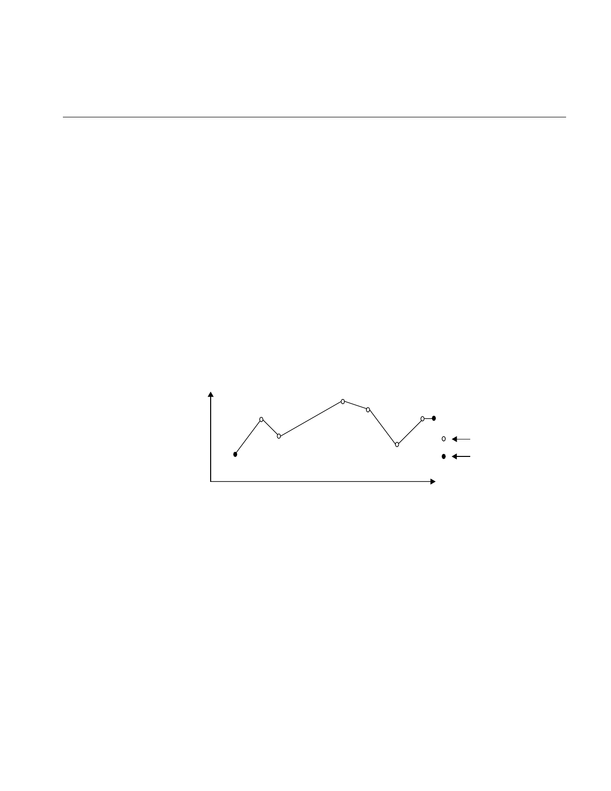
Image Processing Operators Provided with IL
143
You can dynamically change or retrieve the LUT with these functions:
ilStatus setLookUpTable(const iflLut& table);
If you change the LUT, the output number of channels and data type are updated, if
necessary, to accommodate the new LUT.
ilPiecewiseImg
The ilPiecewiseImg class, derived from ilLutImg, simplifies the task of constructing a
lookup table when only a piecewise linear mapping is needed from the input pixels to
the output data. The constructor accepts the source image, a list of breakpoints, and the
length of that list:
ilPiecewiseImg(ilImage* inputImage = NULL,
const iflXYSfloat* bkpts=NULL, int length=0);
Abreakpoint is a point on a piecewise continuous function where two continuous
segments meet, as shown in Figure 4-30.
Figure 4-30 Breakpoints along a Piecewise Continuous Function
The endpoints, 0 and 255, are made breakpoints by default (this does not affect the length
of the breakpoints list). If a breakpoint is entered outside the range, it is clamped to the
appropriate endpoint.
Several functions are provided to manipulate the breakpoints:
ilStatus setBreakpoints(const iflXYSfloat* bkpts=NULL,
int length=0, int chan=-1);
ilStatus insertPoint(const iflXYSfloat& point, int index,
int chan=-1);
Breakpoint
Endpoint
0255
Input channel values
Output
channel
values

144
Chapter 4: Operating on an Image
ilStatus replacePoint(const iflXYSfloat& point, int index,
int chan=-1);
ilStatus removePoint(int index, int chan=-1);
setBreakpoints() allows you to specify a new list of breakpoints (of length). You
can specify a list for a specific channel with the chan argument;
if this is minus 1 (the default), the list is used for all channels in
the image.
insertPoint() inserts a breakpoint point after the one at index in the list for
channel chan.
replacePoint() replaces the breakpoint at index in the breakpoint list for
channel chan with point.
removePoint() removes the breakpoint at index; you specify which channel’s
breakpoint list with chan.

Image Processing Operators Provided with IL
145
You can query an ilPiecewiseImg about its breakpoints with these functions:
int getBreakpoints(iflXYSfloat* bkpts, int chan=0);
int getNumBreakpoints(int chan=0);
void getPoint(iflXYSfloat& point, int index, int chan=0);
float findPoint(iflXYSfloat& loc, int& index,
int forInsert=0, int chan=0);
In all of the above functions, chan is 0 by default, specifying the first channel of the image.
Figure 4-31 shows an example of an application with a graphical user interface (imgview)
that can be written with ilPiecewiseImg.
getBreakpoints() accepts a pointer to a list of breakpoints and returns the
length of the breakpoint list for chan as an int and the
breakpoint list itself through bkpts (you must allocate
enough space in bkpts before this function call).
getNumBreakpoints() returns the number of breakpoints in the breakpoint list
for chan.
getPoint() returns the breakpoint at index in the breakpoint list for
chan by reference in point.
findPoint() accepts a location (loc), an index into the breakpoints list for
chan, and a flag specifying whether the closest breakpoint
should be found (forInsert = 0) or whether the closest edge
should be found (forInsert = 1). In either case, the distance
between the given location and the found location is
returned as a float, the breakpoint is returned by reference
in loc, and the index of that breakpoint is returned in index.
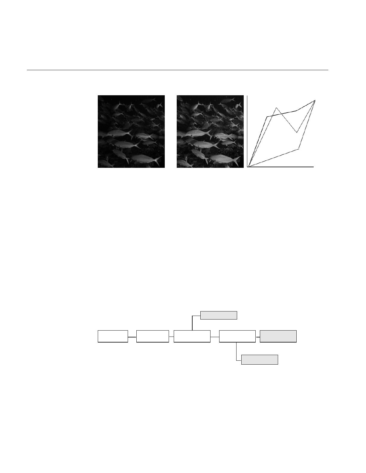
146
Chapter 4: Operating on an Image
Figure 4-31 Using a Lookup Table Editor to Set Breakpoints
Combining Images
The three operators described in this section—ilBlendImg, ilMergeImg, and
ilCombineImg—combine two or more images into one using different methods:
•ilBlendImg blends two images using a specified alpha value or alpha images that
indicate how to weight the images relative to each other.
•ilMergeImg merges a series of images into a single multiple-channel image.
•ilCombineImg combines two images using a mask to define which portions of the
two images to use in the final combined image.
These three classes have very different pedigrees, as shown in Figure 4-32.
Figure 4-32 ilBlendImg, ilMergeImg, and ilCombineImg Inheritance Hierarchy
Original Edited LUT Editor RGB Interface
ilImage ilBlendImgilOpImg ilPolyadicImg
ilMergeImg
ilCombineImg
ilCacheImg

Image Processing Operators Provided with IL
147
ilBlendImg
The constructors for ilBlendImg allow you to specify a constant alpha value or to specify
third and fourth images that contain alpha values for each pixel of the foreground and
background images. You can also select the way in which the foreground and
background images are blended:
ilBlendImg(ilImage* fore, ilImage* bkgd, float alpha);
ilBlendImg(ilImage* fore = NULL, ilImage* bkgd = NULL,
ilImage* alphaf = NULL, ilImage* alphab=NULL,
ilCompose comp=ilAplusB);
The first constructor specifies one constant alpha value (which should fall between 0.0
and 1.0) that is used to calculate a foreground and background alpha. If the second
constructor is used, the alpha values are taken from the first channel of alphaf (for the
foreground alphas) and alphab (for the background alphas). The other channels, if any, are
ignored. In the default mode (ilAplusB), if alphab is NULL, then the background alpha
values for each pixel are computed from alphaf as 1 - alphaf. Figure 4-33 shows an example
image produced using the ilBlendImg operator and the ilAplusB compose mode.
The second constructor also allows you to specify the composition mode. See Figure 4-34
for an explanation of these modes. The default is ilAplusB. The composition modes are
defined in the header file il/iflDataTypes.h.
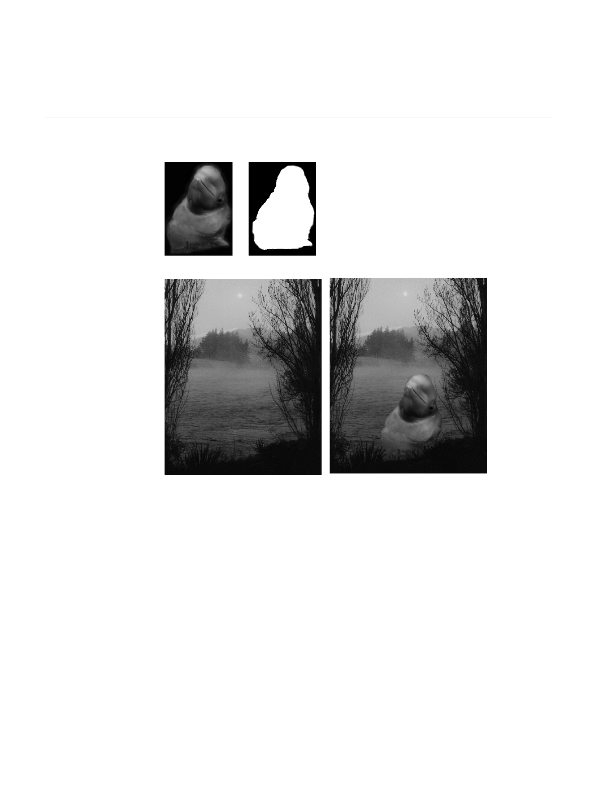
148
Chapter 4: Operating on an Image
Figure 4-33 Blended Images
The foreground, background, and alpha images must all be the same size. The alpha
values defined by alphaf and alphab are normalized to the range (0-1), based on the
minimum and maximum allowable pixel values of alphaf and alphab. The foreground and
background alphas are calculated as follows:
foreα = alpha , backα = 1 - alpha or
foreα = alphaf, backα = alphab (if alphab is not NULL), and
backα = 1 - alphaf (if alphab is NULL)
Original 1
Original 2 Blend of 1 and 2
Original Mask

Image Processing Operators Provided with IL
149
The blending function, which is used for each pixel, is:
The composition mode determines FA and FB. For the default composition mode
(ilAplusB), they are both equal to 1.0, see Figure 4-34.
If ilImgA is the foreground image and ilImgB is the background image, then
αA = alphaf and αB= alphab .
However, when alphaB=NULL, then
αB = alphaf
You may set the composition method with setBlendMode(). It takes one argument of
type ilCompose:
void setBlendMode(ilCompose mode = ilAplusB);
You can explicitly set the minimum and maximum allowable pixel values of the alpha
images alphaf and alphab using these functions:
void setAlphaRange(float fmin, float fmax);
void setAlphaRange(float fmin, float fmax,
float bmin, float bmax);
The first function sets the normalizing values for the foreground alpha. The second sets
the minimum and maximum values of the alpha for the foreground and background
images.
To query an ilBlendImg about its normalizing values, use:
void getAlphaRange(float& fmin, float& fmax);
void getAlphaRange(float& fmin, float& fmax,
float& bmin, float& bmax);
The first function returns the normalizing values for the foreground alpha, and the
second function returns the normalizing values for both the foreground and background
alphas. You can also dynamically change the alpha images or the constant alpha value:
ilStatus setAlphaPlane(ilImage* alphaImg);
ilStatus setAlphaPlane(ilImage* alphaf, ilImage* alphab)
ilStatus setConstAlpha(float val);
FAforeground foreαFBbackground backα⋅⋅+⋅⋅
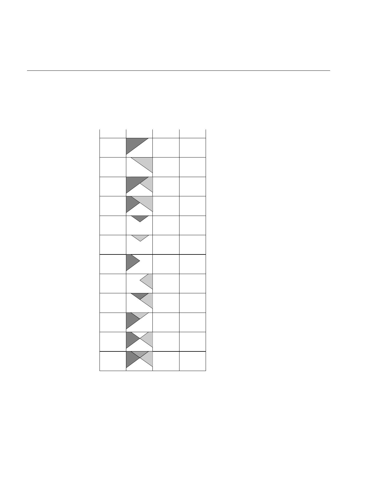
150
Chapter 4: Operating on an Image
The first function shown above sets the foreground alpha image, while the second
function sets both the foreground and background alpha images. The third function sets
the constant alpha value. You can also use setOffset() (inherited from ilPolyadicImg) to
offset the foreground image with respect to the background image.
Figure 4-34 Composition Modes for ilBlendImg
ilImgA
ilImgB
ilAoverB
ilBoverA
ilAinB
ilBinA
ilAoutB
ilBoutA
ilAatopB
ilBatopA
ilAxorB
ilAplusB
1
0
1
1−αΒ
αΒ
0
1−αΒ
0
αΒ
1−αΒ
1−αΒ
1
0
1
1−αΑ
1
0
αΑ
0
1−αΑ
1−αΑ
αΑ
1−αΑ
1
Mode Diagram FAFB

Image Processing Operators Provided with IL
151
ilMergeImg
An ilMergeImg consists of a single ilImage formed by merging a number of images. The
number of channels of the merged image equals the sum of the number of channels in all
the individual input images. All the input images should be the same size, but you can
assign a different data type or order to the final ilMergeImg as it is created:
ilMergeImg(ilImage** imgPtr, int nimg,
iflOrder order=iflInterleaved,
iflDataType dtype=iflDataType(0));
ilMergeImg(int nimg, ilImage** imgPtr);
In both of these constructors, imgPtr is an array of pointers to the ordered input ilImages.
The first nimg ilImages in the array are merged and the rest are ignored. (imgPtr should
have at least nimg pointers.) The first constructor lets you specify an order and data type
for the merged image. If the default data type numilTypes is used, the data type of the
merged image is the largest data type of the ilImages. If the second constructor is used,
the order and data type of the merged image are the same as those of the first ilImage
pointed to in the imgPtr array.
ilCombineImg
An ilCombineImg takes two ilImages of the same size and uses an ROI (and its offsets)
to determine which pixels to use in the final image (pixels that are inside the ROI are
taken from the foreground image, and pixels that are outside the ROI are taken from the
background image):
ilCombineImg(ilImage* fore=NULL, ilImage* bkgd=NULL,
ilRoi* roi=NULL,int xoffset=0, int yoffset=0,
int zoffset=0);
See “Defining a Region of Interest” on page 153 for more information about creating an
ilRoi object. The xoffset and yoffset parameters specify the offsets at which the ROI is
placed in the foreground and background images; they are specified in the coordinate
space of the fore image. You can change the ROI and its offsets after the combined image
is created, and you can obtain a pointer to it with these ilHistScaleImg functions:
void setRoi(ilRoi* roi, int xoffset = 0, int yoffset = 0,
zoffset = 0);
ilRoi* getRoi();

152
Chapter 4: Operating on an Image
Constant-valued Images
The ilConstImg class allows you to create an object that returns a constant value
whenever its data is read. You might use this class as an input to one of the operators
described in the “Dual-input Operators” on page 94, for example, to multiply each pixel
in an image by a constant value. Remember that ilConstImg is not an operator since it
derives directly from ilImage.
The ilConstImg class defines only one function, its constructor:
ilConstImg(const iflPixel& fill);
The specified iflPixel is the value returned whenever the image’s data is read, regardless
of how much data is read. Since an ilConstImg stores only one iflPixel, it uses much less
memory than, for example, an ilMemoryImg filled with pixels. To change an
ilConstImg’s pixel value after you have created an ilConstImg object, use the setFill()
function defined in ilImage and described in “Fill Value” on page 29.
Using a Null Operator
As its name suggests, the ilNopImg operator performs no operation at all. It is useful for
caching the results defined by a non-cached class, such as ilMemoryImg (described in
“Importing and Exporting Image Data” on page 78). it is also useful if you just want to
change some of the attributes of any image (for example, data type, data ordering, or
page size) and need to cache the result. Note that this class is a real operator, as it derives
from ilMonadicImg.
The ilNopImg class defines one public member function, its constructor:
ilNopImg(ilImage* inputImage = NULL);
An image stored as an ilMemoryImg cannot take advantage of IL’s on-demand paging
mechanism, since it does not derive from ilCacheImg. ilNopImg, however, is derived
(indirectly) from ilCacheImg. Thus, storing that ilMemoryImg as an ilNopImg allows
you to page that image.

Defining a Region of Interest
153
Defining a Region of Interest
Some IL programs, especially those that deal with large images, may need to apply an
operator to only a portion of an entire image. When this is the case, you can restrict the
processing area to a region of interest (ROI). An ROI allows you to modify irregular
regions of an image. IL provides two principal classes that let you restrict the data that
can be accessed:
•ilRoiImg, which associates a ROI with an image so that subsequent operations on
the image affect only the data inside the ROI
•ilSubImg, which allows a rectangular portion of an image to be treated as if it were
an independent image
In some situations, these two classes might appear to have similar effects, but they
actually achieve their results through very different means, and they have different uses.
ilRoiImg, derived from ilCombineImg, is the same size as the initial image. The
difference is that portions of the ilRoiImg are “masked out”—set to a specified
background value—so that they will not be affected by processing. You use an ilRoiImg
when you wish to modify a portion of an image while leaving the rest of the image intact.
This is the traditional masking, or ROI, concept.
ilSubImg, derived from ilOpImg, does not actually hold any data itself; it merely
implements the standard data access ilImage functions—getSubTile3D(),
setSubTile3D(), and copyTileCfg()—so that they access only the data in the subimage.
When you call one of the access functions, you specify the origin and size of the desired
tile in the subimage. The ilSubImg maps the coordinates of the desired tile to the source
image so that the correct data is accessed. An ilSubImg can be used as a rectangular ROI,
but it is most useful for manipulating the input images to an operator to achieve
particular results. For example, you can use an ilSubImg to offset two images relative to
each other before they are fed into an ilAddImg operator to be added together. (You can
also do this with the ilPolyadicImg.setOffset() function in ilPolyadicImg.) Or you can
select the red and blue channels of an image using two ilSubImgs and then add them
together.
Once you have created either an ilSubImg or an ilRoiImg, you can use it in an operator
chain just as you would any other ilImage. You can also write data back into ilSubImg or
ilRoiImg, which you cannot do with an operator (since all operators are read-only).
When you do write data back into an ilSubImg or an ilRoiImg, the input image is
modified appropriately. The next sections describe how to use these two classes.

154
Chapter 4: Operating on an Image
Creating an ilRoiImg
Typically, you use an ilRoiImg when you are displaying processed data or writing it to a
file. By restricting the area that needs to be processed, you can prevent data from being
processed unnecessarily.
Before you can create an ilRoiImg, you need to create the following:
•the source ilImage that is to be masked with the ROI
•the actual ROI itself, in the form of an ilRoi object
•the x and y offsets for placing the ROI into the source image
•the background value, an iflPixel, that is used to fill areas outside the ROI
The source image can be any ilImage, and it can be part of an already existing operator
chain. The background value defines the ilImage’s values outside the ROI. As shown
below, the constructor for the ilRoiImg class takes pointers to all three of these objects:
ilRoiImg(ilImage *Img, ilRoi *Roi, iflPixel &bkgd,
int xoffset=0, int yoffset=0);
This constructor associates the ilRoi with the source ilImage and sets the ilRoiImg’s
background value. The xoffset and yoffset values determine where the ROI is placed; they
are specified in the src image’s coordinate space. Subsequent operations to the ilRoiImg
affect only the image data inside the specified ilRoi. Any attribute of an ilRoiImg that is
not explicitly set is inherited from its source image.
Once an ilRoiImg is created, you can modify its associated ilRoi or the background value
by calling ilHistScaleImg.setRoi() or ilRoiImg.setBkgd(). These ilHistScaleImg
functions take a pointer to the desired ilRoi or iflPixel:
void setRoi(ilRoi* roi, int xoffset = 0, int yoffset = 0);
void setBkgd(iflPixel& bkgd);
You can also query an ilRoiImg about its ROI or background value:
ilRoi* getRoi();
void getBkgd(iflPixel& bkgd);
The ilRoi base class defines the basic concept of a region of interest in IL. It is an abstract
class, so you must use one of the classes that derive from it to create an ROI. (You can also
derive your own class to define an ROI that more specifically matches your needs. See
“Deriving From ilRoi” on page 242 to learn more about deriving from ilRoi.) An ilRoi is
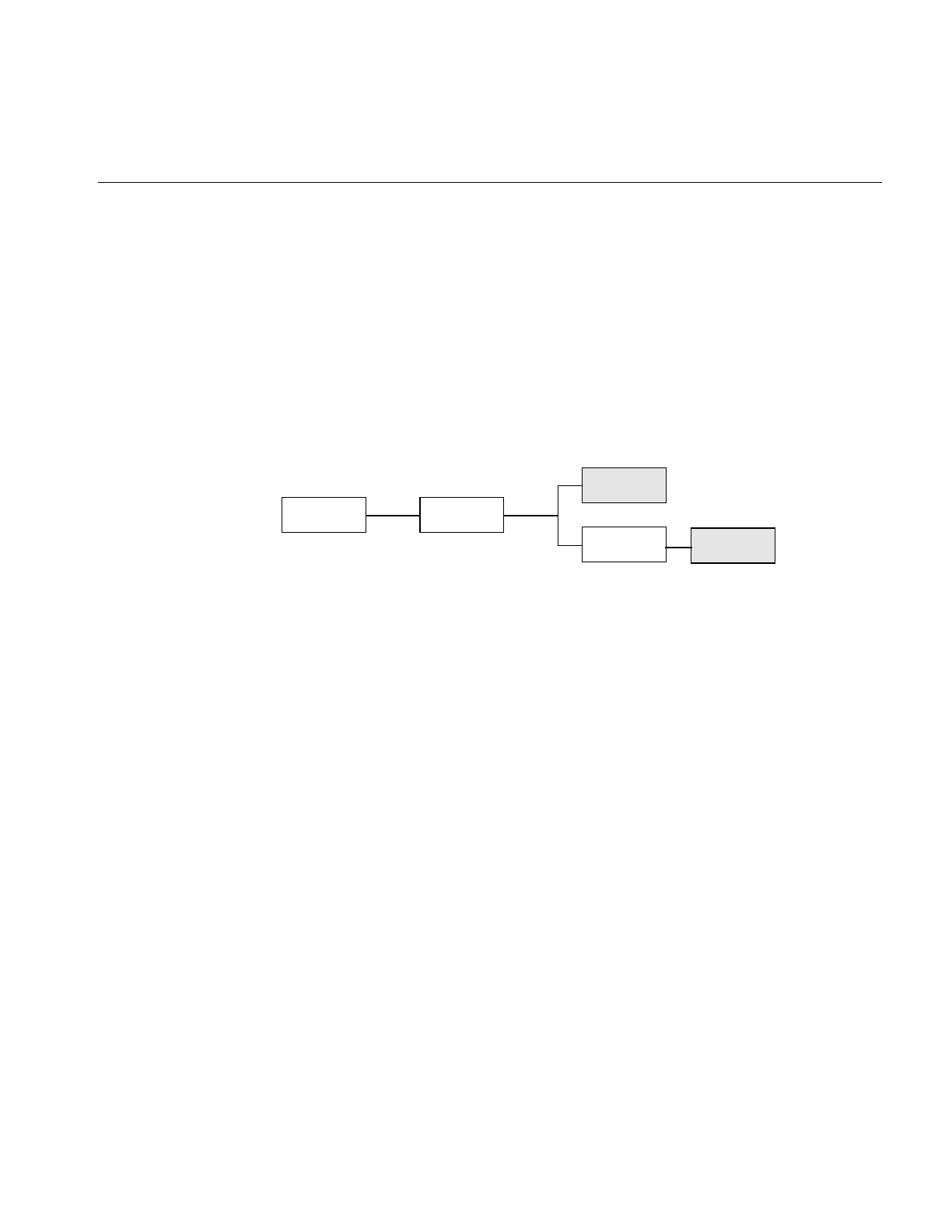
Defining a Region of Interest
155
a two-dimensional object with its own x and y dimensions and its own coordinate space.
If you imagine the ilRoi placed on top of the image and yourself viewing it from above,
you would see regions of the image inside and outside the ilRoi. The regions inside are
considered valid and are accessible for image processing operations; those outside the
ilRoi are invalid and are typically set to a background value for processing. The same
ilRoi can be associated with different images (which can be different sizes), and it can be
placed at different offsets within each image. This functionality is achieved through the
ilRoiMap class, which is described later. You manage the ilRoi’s coordinate space with
ilRoi.setOrientation() and ilRoi.getOrientation().
Currently, IL provides two classes derived from ilRoi, as shown in Figure 4-35.
Figure 4-35 lRoi’s Subclasses
An ilRectRoi defines a rectangular ROI, and an ilBitMapRoi defines a bitmap of any
shape that can be used as an ROI.
A Rectangular ROI
As its name suggests, ilRectRoi allows you to define a rectangular ROI:
ilRectRoi myRoi(20, 30, 1);
All the arguments for the ilRectRoi constructor are of type int. The first two specify the
sizes in the x and y dimensions (20 and 30) of the rectangle to be used as the ROI. The
optional last argument, which can be either 1 or 0, indicates whether the area inside or
outside the rectangle should be considered the valid area. The default value is 1, which
defines the inside of the rectangle as the valid area. You specify the image that the
ilRectRoi is associated with and the offsets into the image later so that the same ilRectRoi
can be used for different images at different offsets. In addition, operators that take an
ROI as an input also take the offsets as arguments.
ilRectRoi
ilRoiilLink
ilBitMapRoi
ilImgRoi
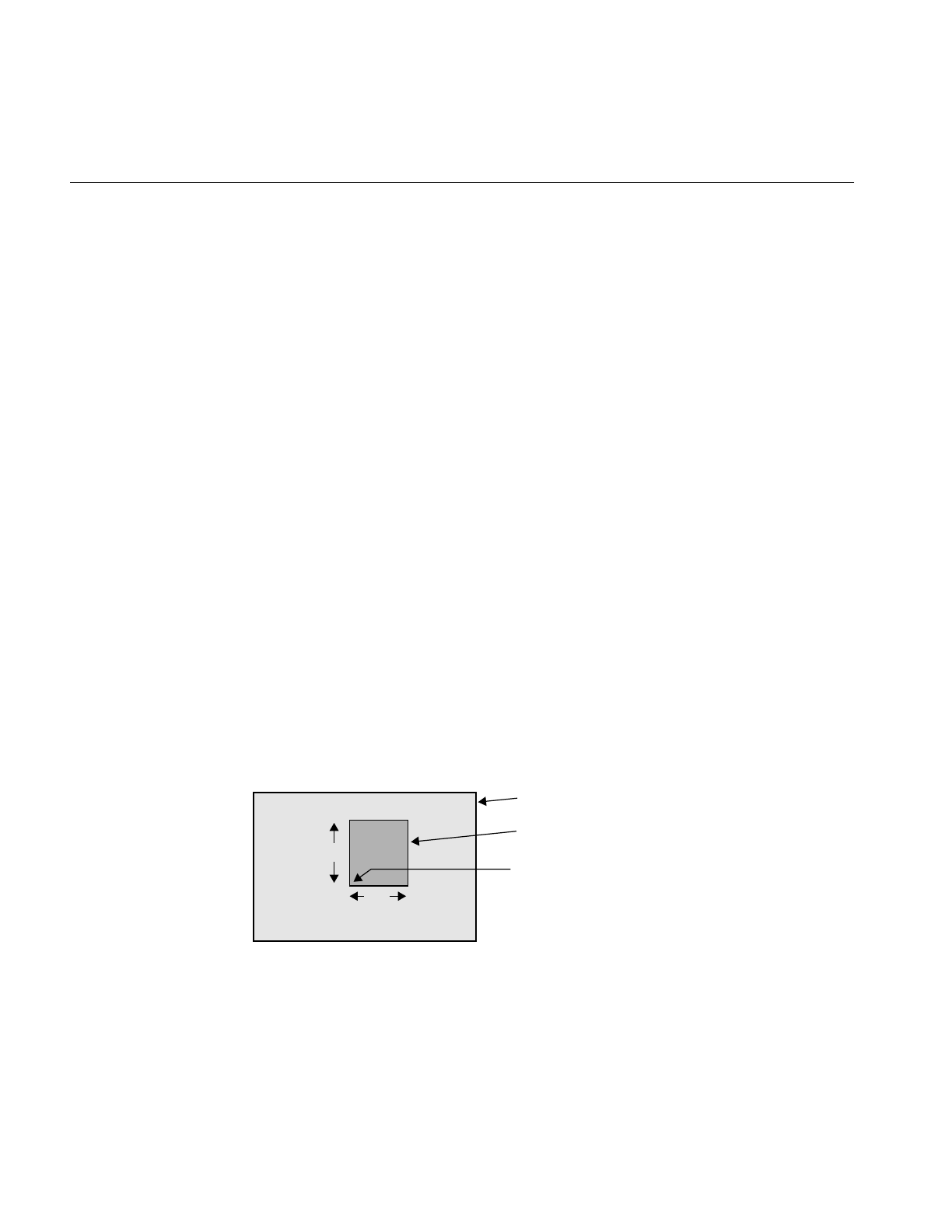
156
Chapter 4: Operating on an Image
You can also determine which is the valid area (the inside or the outside of the rectangle)
and change the current designation:
int getValidValue();
ilStatus setValidValue(int val);
The first function returns either a 1 or a 0 to indicate that the inside or the outside is valid,
and the second function sets the valid area.
Creating an ilSubImg
The ilSubImg class defines three constructors that let you create a subimage that is a
different size from the source image. The first constructor is for two-dimensional images,
the second for three-dimensional images, the third for four-dimensional images, and the
last for use as a NULL constructor.
ilSubImg(ilImage *src, int xs, int ys, int xsz, int ysz,
ilConfig* config = NULL);
ilSubImg(ilImage *src, int xs, int ys, int zs, int xsz,
int ysz, int zsz, ilConfig* config = NULL);
ilSubImg(ilImage *src, ilConfig *config);
ilSubImg();
The first argument in all of these functions is a pointer to the source image. The next
arguments specify the location of the origin of the subimage (xs,ys, zs, and cs), measured
in pixels in the source image, and the dimensions of the subimage (xsz,ysz,zsz, and csz),
as shown in Figure 4-36. (This figure assumes that the subimage’s coordinate space is
iflLowerLeftOrigin.) If the dimensions are larger than the source image, the subimage is
padded with the source image’s fill value.
Figure 4-36 Source Image and Subimage
xsz
ysz
Source Image
Subimage
(xs, ys)
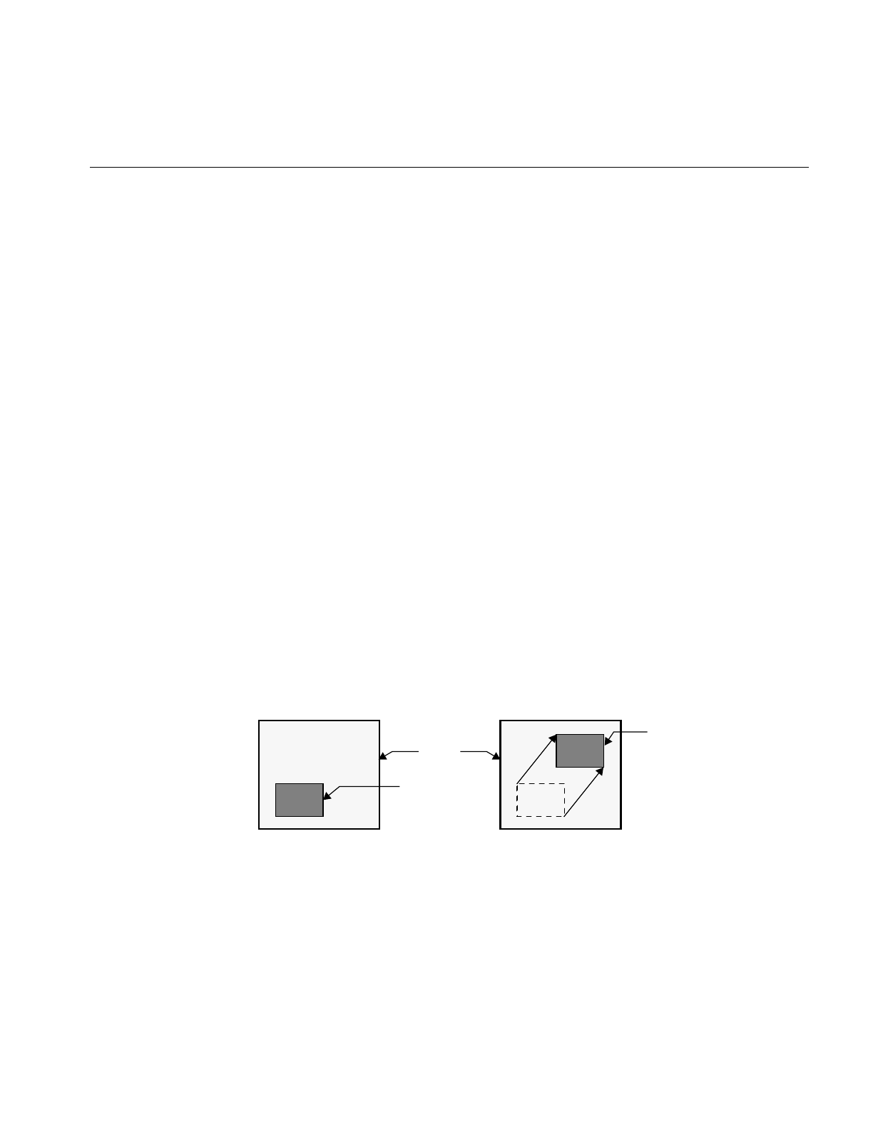
Defining a Region of Interest
157
The last, optional argument for these constructors is a pointer to an ilConfig object that
specifies the configuration of the subimage. If this argument is not supplied, the
subimage inherits its configuration from the source image.
Another constructor is provided for convenience when the subimage has the same size
as the source image but a different configuration:
ilSubImg(ilImage* src, ilConfig* config);
You can use the ilConfig argument for any of these constructors to select a subset of the
source image’s channels and to reorder them; you can also use it to set the coordinate
space, data type, and pixel ordering of the subimage.
Once you have created an ilSubImg, you can modify several of its attributes—size, data
type, order, color model, and coordinate space—using the functions defined in ilImage.
To change an ilSubImg’s configuration after you have created it, use setConfig(). This
function takes a pointer to an ilConfig and modifies the ilSubImg accordingly. Any
attribute of an ilSubImg that is not explicitly set is inherited from its source image.
You can also translate the origin of a subimage after it is been created:
const int xorigin = 20;
const int yorigin = 20;
mySubImg.setMouse(xorigin, yorigin);
As shown, setMouse() expects const int arguments. For a three-dimensional image,
supply a third argument for the z dimension. For a four-dimensional image, supply a
fourth cdimension. The ilSubImg’s origin, not its size, is affected by setMouse(), as
shown in Figure 4-37.
Figure 4-37 Translated Subimage
Image
Subimage
Translated
Subimage

158
Chapter 4: Operating on an Image
You can also query a subimage about its origin using one of the following methods:
ilDisplay.getMouse(int& x, int& y);
ilDisplay.getMouse(int& x, int& y,
iflOrientation orientation);
As shown, the overloaded getMouse() retrieves the origin by reference.
The virtual method, ilImage.hasPages(), indicates whether a class implements paging
and is defined by ilSubImg. It returns TRUE if its parent implements paging and FALSE
otherwise.

159
Chapter 5
5. Displaying an Image
This chapter describes how to display and manage a set of images on the screen using
IL’s display facility. As part of this facility, numerous functions are provided to help you
develop an interactive image-processing program. You can use these functions to move
images, perform wipes, roam around an image, and create split views of multiple
images.
This chapter describes IL’s display facility in the following major sections:
•“Overview of the Display Facility” on page 160 describes the sequence of
operations you must perform to display an image.
•“A Simple Interactive Display Program” on page 165 lists and describes a program
that opens an image file, performs an operation on it, and allows interactive
viewing of both images.
•“Creating an ilDisplay” on page 169 describes in detail how to open a window and
create an ilDisplay.
•“View and Display Basics” on page 171 describes basic concepts such as setting
background color and page borders and deferring drawing of a view.
•“Managing Views” on page 177 describes how to manage the view stack and how
to retrieve information from views.
•“Applying a Display Operator” on page 184 tells you how to use display operators
to draw views, relocate or resize them, and update them.
•“A More Complicated Interactive Display Program” on page 196 contains a
program illustrating control of a display.
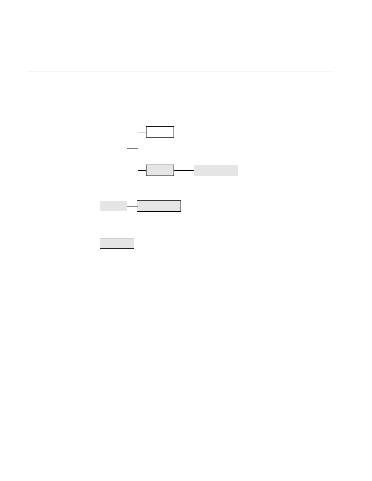
160
Chapter 5: Displaying an Image
Overview of the Display Facility
IL display classes described in this chapter are shown shaded in Figure 5-1.
Figure 5-1 IL Display Classes
With IL’s display facility, you can display any combination of IL or X images in an X or
OpenGL window. These images can be positioned anywhere within the window and can
overlap each other.
Overlapped regions are displayed based on a stacking order such that the image on top
is visible, as shown in Figure 5-2.
ilLink
ilDisplay
ilImage
ilView ilStereoView
ilViewer
ilGLXConfig
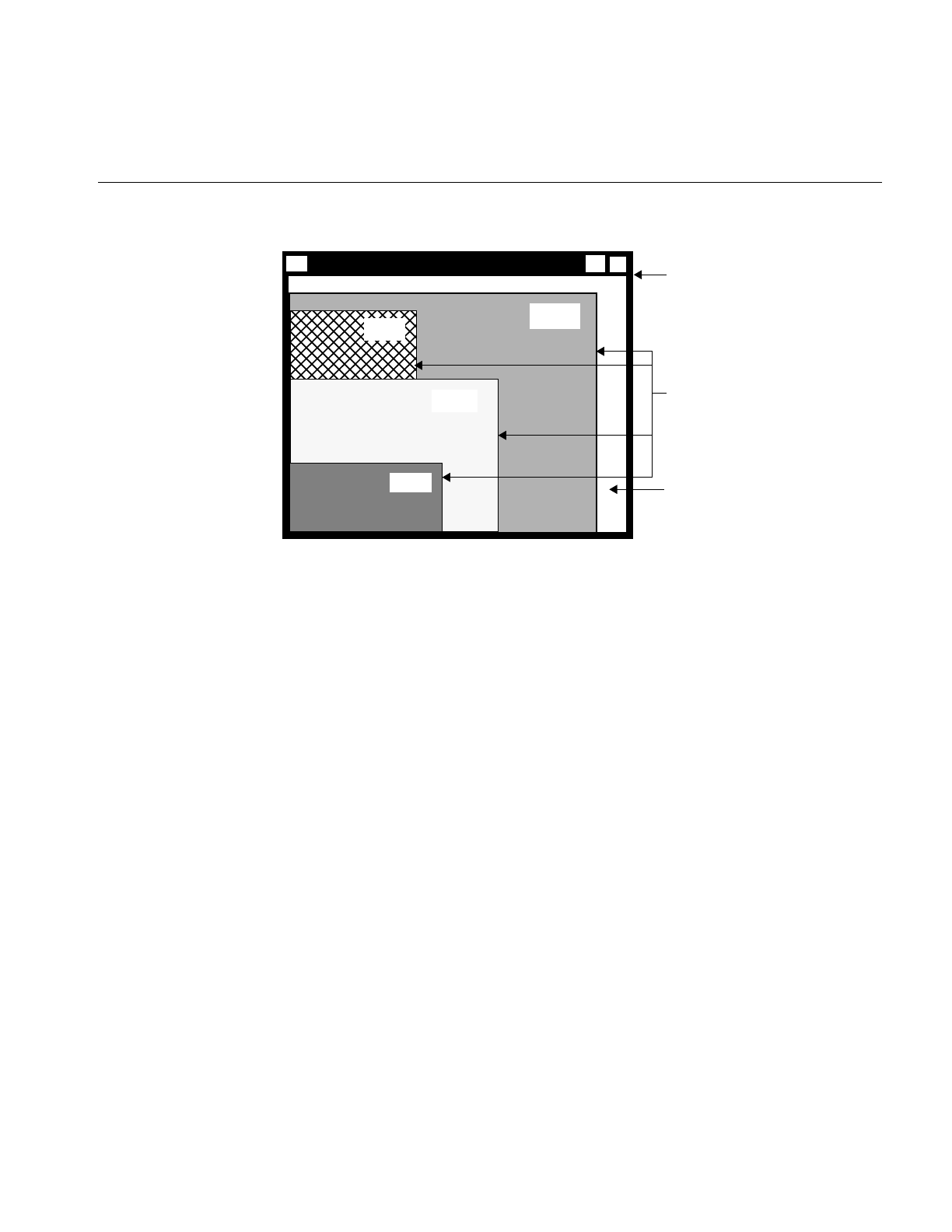
Overview of the Display Facility
161
Figure 5-2 Stacked Images in an X Window
In order to assemble such a display, you must follow these steps:
1. Create or open the images.
You can display any combination of ilImage, ilXImage, or XImage using either
OpenGL or X to render them. (An XImage is an X Window struct.) Often, displayed
images are the product of an image processing chain. For example, you might want
to display the original unprocessed image, an intermediate stage of the chain, and
the final image. In some cases, you might want to display only a portion of an
image.
2. Configure and open a window.
To open an X window, use the standard X calls. To open a OpenGL window, use the
OpenGL calls explained in “A Sample Program in C++” on page 2.
3. Create a display.
Use calls to ilDisplay functions.
4. Add the images to the display.
Use calls to ilDisplay functions.
5. Cause the images to be displayed.
Use calls to ilView and ilDisplay functions.
ilViews
Background
(display area)
X Window
addView(Img1)
addView(Img2)
addView(Img3)
addView(Img4)
Img4
Img3
Img2 Img1
Assuming:

162
Chapter 5: Displaying an Image
Note: You should assume that any function discussed in this chapter is an IL function,
unless it is explicitly identified as a OpenGL or X function.
The three principal classes within the IL display facility are
•ilDisplay—Manages one or more ilViews in an X or OpenGL window. The entire
window is used for display. An ilDisplay object maintains a stack of ilViews and
provides functions to manipulate them. ilViewer derives from ilDisplay, which
manages the display of images in an X window with X event handling.
•ilView—Maps an ilImage or XImage to a region within the ilDisplay. It has various
attributes such as view position, view size, image position, border color, and border
width.
•ilFrameBufferImg—Acts as a base class for images that reside in the frame buffer.
There is one derived classes: ilXWindowImg.
When an ilDisplay is created, it creates an ilXWindowImg for X rendering. The display
image is configured to occupy the entire window specified by the application. As
Figure 5-3 illustrates, the creation of an ilDisplay object defines a display area in which
views are drawn.
Figure 5-3 ilDisplay Object Creates a Display Area
When you want to add an image to ilDisplay, create an ilView to control where you want
the image to be displayed. This view is pushed onto an indexed view stack and a pointer
to it is returned to your application. As you add more images, you must create an ilView
for each image. These views are pushed onto the view stack. When a view is added to the
stack, it is pushed onto the top by default. However, you can specify a particular index
to control where the view is put in the view stack. An ilView has various attributes, such
as
Display Area
X Window
ilDisplay
object
Memory
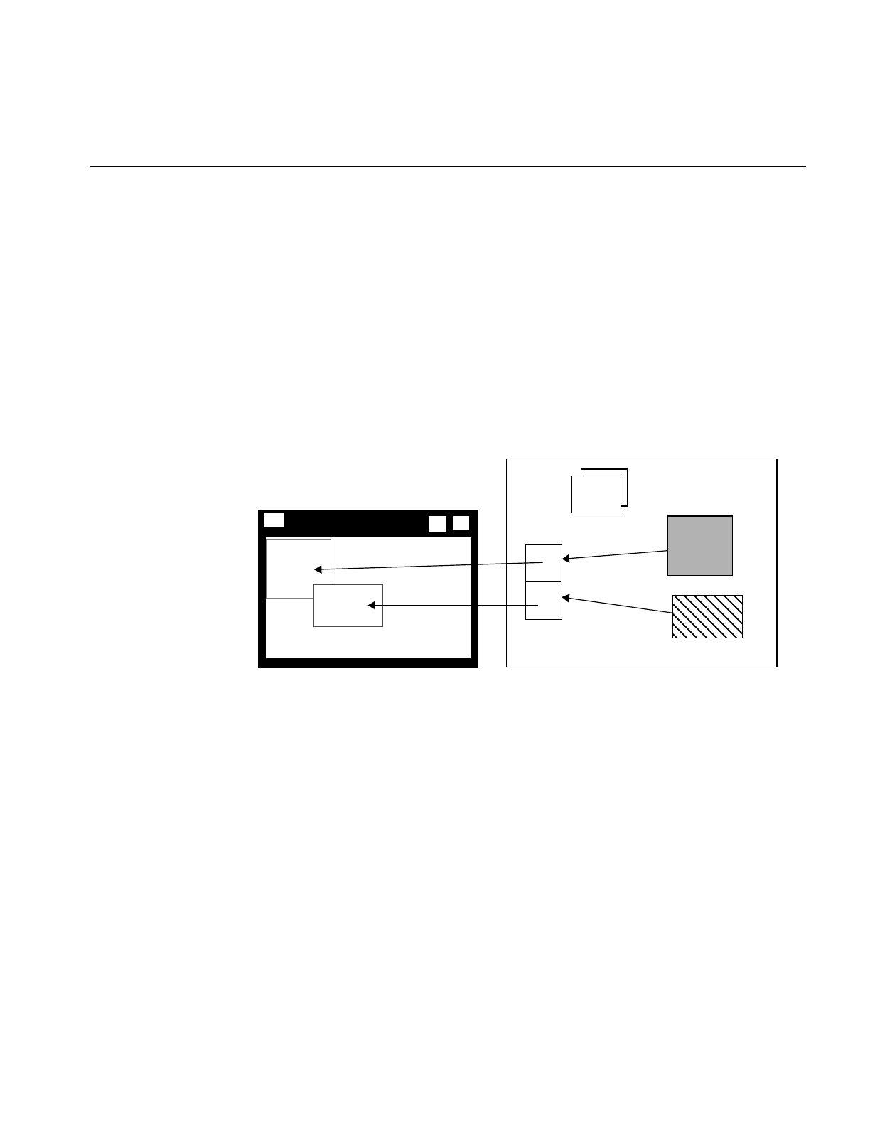
Overview of the Display Facility
163
•view position, which controls where in the window the image is displayed
•view size, which controls how much of the image is displayed
•image position, which controls what part of the image is displayed
The position of an ilView in the view stack controls its visibility on the screen, as shown
in Figure 5-2. The view on the top of the stack is fully visible. A view at the bottom of the
stack is obscured by the views above it.
In Figure 5-4, two ilView objects have been created and the positions of the
corresponding views in the display defined. Two images to be displayed have been
added to the view stack.
Figure 5-4 ilView Objects Map Images to Display Regions
When ilDisplay draws its contents, the position and size of each ilView, as well as the
stacking order, are used to determine what portion of each view is visible.
ilFrameBufferImg is called to render the images into the frame buffer. Each image is
converted to the proper data type, order, color model, and coordinate space as necessary
for displaying. Figure 5-5 shows the display after the views have been drawn.
view1
view2
view stack
Img2
Img1
addView(Img2)
addView(Img1)
Memory
ilView
objects
top

164
Chapter 5: Displaying an Image
Figure 5-5 Display Area After Views Are Drawn
In addition to the views added by an application, ilDisplay creates a background view.
This background view is the size of the window and is always at the bottom of the view
stack. You cannot control it other than to change its color from the default, which is black.
ilDisplay provides several operators to manipulate ilViews as well as functions to
facilitate interactive display. The display operators enable you to move a view, change its
size, or move the image within the view. The display operators are discussed in detail in
“Applying a Display Operator” on page 184. By default, view manipulation also causes
the display to be redrawn; however, a sequence of display operations can be performed
with drawing deferred. In addition, an application can explicitly control drawing.
ilDisplay is optimized to draw only the areas that have changed or that have been
exposed.
Scrolling Windows
You can change the size of the image by reducing its display size. By making the image
size smaller than the display, you, in effect, create a scrollable window. To set and read
the visible area in which an image can display, you use the setVisibleArea() and
getVisibleArea() functions in ilDisplay, defined as follows:
void setVisibleArea(int x = 0, int y = 0, int nx = 0,
int ny = 0);
void getVisibleArea(int& x, int& y, int& nx, int& ny);
The arguments define the lower left and upper right coordinates of the visible display
area.
view1
view2
view stack
Img2
Img1
Display(view1)
Display(view2)
Memory
top

A Simple Interactive Display Program
165
A Simple Interactive Display Program
Now look at a simple interactive program that shows the IL display facility in action.
This program opens an image file and applies a threshold operator to it. Both the original
image and the processed image are displayed in a window, stacked on top of each other.
You can wipe the original image away gradually so that you can see the processed image
beneath it. Wiping changes the view size. The best way to understand wiping, of course,
is to compile and run the display program. It is available online in
/usr/share/src/il/guide/displayEx.c++
When you run the program, you see a window displaying the original image. The
processed image is actually underneath the original one, but you cannot see it, since the
images are opaque and of the same size. If you click in the window with the left mouse
button, a red highlight border appears around the image, indicating that it is ready to be
wiped. To wipe, click the left mouse button near any edge of the image and drag toward
the center of the image. As you drag, the processed image becomes visible as the original
image is wiped away; release the button to stop the wiping. You can wipe any edge or
corner of the original image. To exit the program, use the normal window manager menu
command.
Sample Program Code
The code for the sample program is shown in Example 5-1 and discussed in the
paragraphs following that. All the ilDisplay functions used in the program are explained
in more detail in the appropriate sections in this chapter.
Example 5-1 A Simple Interactive Display Program
#include <stdlib.h>
#include <stdio.h>
#include <il/ilFileImg.h>
#include <il/ilThreshImg.h>
#include <il/ilDisplay.h>
const int Border = 10; // Threshold in pixels for edge finding
operation
void
main (int argc, char* argv[])

166
Chapter 5: Displaying an Image
{
if (argc < 2) {
printf (“Usage: %s in-image1\n”, argv[0]);
exit(0);
}
// Step 1: Open an image file and create a threshold image.
ilFileImg in(argv[1]);
if (in.getStatus() != ilOKAY) {
char buf[400];
fprintf(stderr, “Could not open image file %s: %s\n”,
argv[1], ilStatusToString(in.getStatus(), buf,
sizeof(buf)));
exit(0);
}
// Step 2: Create threshold image, open an X window, and create
// ilDisplay object.
float threshVal = 100.;
iflPixel threshPix(iflFloat, 1, &threshVal);
ilThreshImg thresh(&in, threshPix);
iflSize size;
in.getSize(size);
Display* dpy = XOpenDisplay(NULL);
ilDisplay disp(dpy, size.x, size.y);
disp.addView(&thresh);
ilView* inView = disp.addView(&in);
disp.setBorders(TRUE);
// Step 3: Process the image, allowing to wipe between original and
// processed images using the left mouse button.
int active = TRUE;
int wipemode = 0;
Window win = disp.getWindow();
while (active) {
iflXYint winSize;
XEvent event;
XNextEvent(dpy, &event);
switch (event.type) {

A Simple Interactive Display Program
167
case MotionNotify:
// flush the event queue
Window rw, cw;
int rx, ry, x, y;
unsigned int state;
XQueryPointer(dpy, win, &rw, &cw, &rx, &ry, &x,
&y, &state);
if (event.xmotion.state&Button1Mask)
inView->wipe(x, y, wipemode|ilClip);
else
wipemode = inView->findEdge(x, y, Border);
break;
case ButtonPress:
disp.setMouse(event.xbutton.x, event.xbutton.y);
break;
case Expose:
disp.display(NULL, ilDefer|ilCenter);
disp.redraw();
disp.getSize(winSize.x, winSize.y);
break;
case DestroyNotify:
disp.destroyNotify();
active = FALSE;
break;
}
}
XCloseDisplay(dpy);
}
Sample Program Comments
The first half of this program should be familiar to you; it is very similar to the sample
program in Chapter 1, “Writing an ImageVision Library Program.” The first several lines
of code include the necessary header files. If the user specifies fewer than two arguments
(the name of the program and the name of the image file), the program prints an error
message and then exits.

168
Chapter 5: Displaying an Image
Step 1: Open an Input Image File and Create a Threshold Image
The specified image file is opened as an ilFileImg object called in. Next, an iflPixel object
is created for use by the threshold operator; the threshold value chosen for this example
is 100.0. The ilThreshImg operator thresh sets each pixel to its maximum possible value if
the pixel value is greater than or equal to the threshold value, or to its minimum possible
value if it is less than the threshold value.
Step 2: Open an X Window and Create an ilDisplay Object
After the threshold image is created, establish a connection to the X server with the X
function XOpenDisplay().
Next, you create an ilDisplay object by passing in the appropriate X window and display
IDs. As shown, the processed image thresh is added first, and then the original image, in,
is added using addView(). The addView() function creates an ilView for the specified
image, adds it to the display’s view stack, and returns a pointer to the ilView. The pointer
to the ilView associated with in is used later in the program.
The order in which images are added determines their stacking order when they are
displayed; the last view added is on top of the others. In this case, the original image is
displayed on top of (and completely obscuring) the processed image. You can reorder the
views as needed.
The setBorders() function is used with default arguments in this example to highlight all
views in the view stack. You can also specify the border color and width.
Step 3: Process Events
Processing events is a critical task for interactive programs. All of the previously
identified inputs (events) must be handled. The event loop in this example processes
events continuously while the program is active.
The code in the event loop uses the following variables:
active Indicates that the window is still active. It becomes FALSE when the user
selects “Quit” from the window menu.
event Holds the event read from the X event queue with XNextEvent().
winSize Indicates the current size of the window.

Creating an ilDisplay
169
wipemode Indicates which edge of the image to wipe.
x and y Hold the x and y positions of the mouse, respectively, as the user drags
to perform a wipe.
The code in the event loop takes the following actions in response to user actions:
•MotionNotify. As the mouse is moved, the x and y values are accessed with the X
function XQueryPointer(). The current xy location of the mouse is passed to wipe(),
which changes the size of the view by moving one or more edges. While the mouse
button is pressed, motion causes a wipe to be performed. If the mouse button is not
pressed, then findEdge() is called. The findEdge() function returns the edge(s) near
the xy location specified and is saved in wipemode. (In this program, the user must
click within 10 pixels of the edge.) When wipe() is called, wipemode specifies which
edges to wipe.
•Button Press. When the user presses the left mouse button to start wiping, the
setMouse() function is called to save the current x and y mouse positions.
•Expose. The first time through the loop, an Expose event is processed, causing the
entire display to be drawn on the screen with the redraw() function.
•DestroyNotify. When the user quits, the active flag is set to FALSE.
Creating an ilDisplay
To incorporate IL’s display facility in your program, you must follow these steps:
1. Open and configure a window.
2. Create an ilDisplay object to manage the window.
3. Add and manipulate images you want to display.
4. Apply the desired display operator(s) to one or more of the views.
This section discusses the first two of these items. The remaining two items are covered
in detail in following sections.
Opening an X Window and Creating an ilDisplay Object
Before creating an ilDisplay object, you must open a window. To do this, use the standard
X call XOpenDisplay(),. as follows:

170
Chapter 5: Displaying an Image
iflSize size;
in.getSize(size);
Display* dpy = XOpenDisplay(NULL);
An ilDisplay object manages views of images within the window passed to it. If an X
window is passed, render mode specifies whether X or OpenGL should be used to render
the images. The constructor for ilDisplay is shown below:
ilDisplay(Display* display, int width, int height,
int attr=ilVisDoubleBuffer, int minComponentSize=8,
int mode = ilDefault,
long eventMask = ExposureMask | KeyPressMask |
PointerMotionMask | PointerMotionHintMask |
ButtonPressMask | ButtonReleaseMask |
StructureNotifyMask);
The following statement creates an ilDisplay object. It takes as its first argument dpy, the
X connection created with XOpenDisplay(). The other arguments define the size of the
window created by ilDisplay:
ilDisplay disp(dpy, size.x, size.y);
The in.getSize() function returns the size of the window to create, and the values of size.x
and size.y define the X and Y dimensions of the window accordingly.
When an ilDisplay object is created, the display origin is the lower left corner. The entire
window is used for drawing, but this window may be a subwindow within an
application.
Note: The ilDisplay class uses many enumerated types, which are listed in “Enumerated
Types and Constants” on page 369 and the header file il/ilDisplayDefs.h.
Adding a View to the ilDisplay Object
Once you have an ilDisplay object bound to an X window, use the ilDisplay member
functions addView() and setBorders() to display the image, as shown in the following
code:
ilView* inView = disp.addView(&in);
disp.setBorders(TRUE);

Choosing OpenGL or X Rendering
171
The &in value is the input image that is ready for manipulation and display. The
setBorders() function enables the display of the default border, ilDefault, around the
view.
Deallocating the Display
After the user has finished with the image, you deallocate the ilView object, ilDisplay
object, and the X window by calling XCloseDisplay(displayName), where displayName
is the name of the ilDisplay object.
Choosing OpenGL or X Rendering
The ImageVision library supports OpenGL as well as X rendering. IL version 3.1 allows
you to choose between the two with the following ilConfigure methods:
ilStatus ilSetRenderingStyle(Display* dpy, ilRenderingStyle style)
ilRenderingStyle ilGetRenderingStyle(Display* dpy)
where ilRenderingStyle is one of the following enumerations: ilOpenGLRendering or
ilXRendering. By default, ilOpenGLRendering is chosen if available. ilXRendering is
used primarily for rendering to a remote machine that does not support OpenGL.
You use ilSetRenderingStyle() to request a rendering style explicitly. If
ilOpenGLRendering is requested but not supported on the X connection, a status of
ilUNSUPPORTED is returned, and ilXRendering is set.
ilGetRenderingStyle() returns the current style.
View and Display Basics
Once you have created a display object, the next step is to add views to this display and
then apply display operators to these views. Before learning more about views, however,
you need to be familiar with some basic concepts that apply to both displays and the
views contained within them.

172
Chapter 5: Displaying an Image
Background Color
If the images being displayed do not cover the entire display area, the ilDisplay’s
background view is seen in the uncovered areas. The background may also be revealed
if images are dragged around or resized by the user. By default, an ilDisplay uses black
as the background color. You can set the color to any pixel value with setBackground():
myDisp.setBackground(float 0, float 1, float 0);
The three arguments correspond to red, green, and blue, respectively. Each color value is
between 0 and 1, inclusive.
In the previous line of code, the background color is set to green.
You can also retrieve an ilDisplay’s current background color:
myDisp.getBackground(float& red, float& green, float& blue);
The returned values for the references are between 0 and 1, inclusive.
Borders
All ilViews have borders, but by default they are not drawn (that is, they are turned off).
You can use ilView’ssetBorders() to turn borders on (TRUE) or off (FALSE):
void setBorders(int flag);
When borders are turned off, the highlight flag (see “Finding a View” on page 181) is also
turned off. The borders are painted or erased immediately unless painting is deferred.
Note that borders are painted inside the view.
In addition, both the borders and the NOP flag can be controlled using the select
functions on ilView (see “Preventing View Operations” on page 174 to learn more about
the nop flag). When select() is called, borders are turned on and its nop flag is turned off.
When unselect() is called, borders are turned off and its nop flag is turned on. The
isSelected() function returns TRUE if the view is selected, or FALSE otherwise:
void select();
void unselect ();
int isSelected();

View and Display Basics
173
You can also specify the width and color of the borders:
void setBorderWidth(unsigned int bordWidth);
void setBorderColor(float red, float green, float blue);
The first function sets the width of the border in pixels to bordWidth; by default, a border
has a width of two pixels. (bordWidth should be a number greater than or equal to zero.)
The second function sets the color of the border to the specified colors, each with a value
between 0 and 1, inclusive.
For convenience, you may set border parameters on all the views in an ilDisplay’s view
stack by calling the corresponding functions on ilDisplay. (You can exclude particular
views in the stack from being acted upon by these functions by setting a nop flag in each
view you wish to exclude. See “Deferring Drawing” on page 174.) For example:
myDisp.setBorders(TRUE);
myDisp.setBorderWidth(5);
myDisp.setBorderColor(0, 1, 0);
There are no convenience functions for getBorders(),getBorderWidth(), or
getBorderColor() in the ilDisplay class since the information may vary from view to
view.
Border Styles
You can set and read the style of the border using the setBorderStyle() and
setBorderStyle() functions in ilView, defined as follows:
void setBorderStyle(int style = ilViewBdrSolidLines)
{ bStyle = style; setState(ilViewBorders); }
int getBorderStyle() { return bStyle; }
The possible border styles are defined by the following enum:
enum ilViewBorderStyle {
ilViewBdrSolidLines = 0, // Solid lines (old style)
ilViewBdrDashedLines = 1, // Dashed lines
ilViewBdrCornerHandles = 2, // Handles on corners
ilViewBdrMiddleHandles = 3 // Handles on mid-side

174
Chapter 5: Displaying an Image
Preventing View Operations
To keep any view in the stack from being operated upon, use the setNop() function to set
the nop flag:
void ilDisplay::setNop(int nop, ilView* view);
void ilView::setNop(int nop);
If the nop argument is TRUE, then the view will not be operated on. To allow operations
to take place on a view, nop should be FALSE. You can use the function isNop() to
determine the state of the nop flag:
int ilDisplay::isNop(ilView* view);
int ilView::isNop();
If you need to perform an operation on each view in the stack regardless of the value of
each view’s nop flag, pass the ilDop flag in the mode for that operation.
If an operation is called on a view, the nop flag is overridden. For example, the statement
below ignores the nop flag on the specified view:
view->wipe();
Deferring Drawing
Drawing can be deferred by calling setDefer() on ilDisplay or ilView. When used to defer
the display, nothing is drawn; however, each view can be individually deferred as well.
These calls are shown below:
void ilDisplay::setDefer(int def, ilView *view=NULL);
void ilView::setDefer(int def);
In the ilDisplay version, you specify the view in which you wish to defer drawing (the
default is all views) by setting the ilView pointer argument to
•NULL, which causes all views in the view stack to be affected
•a pointer to an ilView in the view stack
You might want to defer drawing until you have made a series of changes to an
ilDisplay’s attributes (or to those of its views) so that they all take effect simultaneously.
You might also want to defer drawing while you apply more than one display operator
to avoid drawing intermediate results. In addition, most of the display operators allow

View and Display Basics
175
you to pass the ilDefer flag (see “Mode Flags” on page 175) to defer drawing. (Display
operators are described in more detail in “Applying a Display Operator” on page 184.)
To defer drawing, call setDefer() and pass TRUE as its def argument. After that, the
display is not redrawn until you call setDefer() with FALSE as its def argument. You can
check whether drawing is deferred with isDefer():
int ilDisplay::isDefer(ilView *view=NULL);
int ilView::isDefer();
This function returns TRUE or FALSE to indicate whether drawing has been deferred or
not.
The Drawing Area
An ilDisplay assumes that it can draw anywhere in the window that is been passed to it.
You can retrieve the current size of the drawing area with getSize(), which returns the x
and y dimensions by reference:
void getSize(int& x, int& y);
Managing the Cache
With global cache management, using ilView to manage the cache on its input is
unnecessary. The various cache management methods on ilView have no effect. For more
information, refer to “The Cache” on page 32 and “Optimizing Use of Cache” on
page 247 for a discussion of the global cache management scheme.
Mode Flags
All the display operators use a mode argument to control the display of views. This mode
is a bitwise-OR’d combination of flags that control the operator. You can use the ilDisplay
member functions, setMode() and clrMode() to set and clear the mode flags.

176
Chapter 5: Displaying an Image
The flags are defined as enumerated values (see il/ilDisplayDefs.h). Some flag types are
described below.
Display Flags
Display flags specify various display modes. Examples are:
•ilClip to clip an image to the edge of the display or view
•ilDefer to defer painting
•ilDop to override the nop flag
Coordinate Flags
Coordinate flags specify how the resizing, relocating, and update operators are to
interpret coordinate values. Examples are:
•ilDelVal where x,y is interpreted as delta relative to the current values
•ilRelVal to interpret the x,y coordinates relative to the starting x,y (starting x,y is
updated)
•ilAbsVal to interpret the x,y coordinates as absolute values
•ilOldRel to interpret the x,y coordinates relative to the starting x,y (starting x,y is not
updated)
Wipe Mode Flags
Wipe mode flags specify the edges in a wipe operation. Some examples are:
•ilTopEdge to do the wipe from the top edge
•ilLeftEdge to do the wipe from the left edge
Align Mode Flags
Align mode flags specify image alignment. Some examples are:
•ilTopLeft to align the view from the top left corner
•ilCenter to align the view to the center of the window or the image to the center of
the view

Managing Views
177
The sample program shown at the beginning of this chapter contains an example of the
use of the mode argument. In this example, the display operator initializes all views in
the view stack, aligns the views to the center of the image, and defers the painting of the
view until later.
disp.display(NULL, ilDefer|ilCenter);
Managing Views
Once an ilDisplay has been created, you can create views of the images you want
displayed. As views are created, they are pushed onto the view stack. You can also
retrieve views from the stack, replace the images within the views with other images,
remove views, and reorder the views in the stack. This section explains how to perform
these tasks.
Note: If an error occurs while rendering part of a view, the offending tile is painted with
the error color (see getErrorColor() or setErrorColor()), and the status is set on ilDisplay.
The error color defaults to magenta, but can be set per view with setErrorColor().
The error color functions are defined in ilView, as follows:
void getErrorColor(float& red, float& green, float& blue)
{ err.get(red, green, blue); }
void setErrorColor(float red, float green, float blue)
{ err.set(red, green, blue); }
The values of the colors are between 0 and 1, inclusive.
Adding Images
The addView() function creates an ilView and adds it to the view stack. The image is
drawn when addView() is called, unless ilDefer is passed in mode. It returns a pointer to
the ilView for the ilImage (or XImage) pointer passed in
ilView* addView(ilImage* img, int index, int mode);
ilView* addView(ilImage* img, int mode=ilCenter);
ilView* addView(XImage* img, int index, int mode);
ilView* addView(XImage* img, int mode=ilCenter);

178
Chapter 5: Displaying an Image
You can call addView() with just the image or the image and the display mode. In this
case, the view index defaults to 0 (top of the stack). If you use the version of addView()
that takes an index, you can specify the location in the view stack where the image is to
go.
The mode parameter controls the creation and position of the ilView. By default, the view
is centered, not clipped to the display window, and is painted after being added.
However, this behavior can be modified using various display mode flags such as ilClip
and ilDefer. See “Mode Flags” on page 175 and the ilDisplay reference page for more
details.
If an image has a z dimension that is greater than one, you can choose which xy plane of
the image to display. By default, the first plane (z = 0) is displayed. To display a different
plane, call setZ() on ilView:
void setZ(int startZ);
The startZ argument specifies the desired plane of the image in the view that the function
is called on. ilView’sgetZ() function takes no arguments and returns the current z plane
being displayed of the corresponding image.
Stereo Viewing
If your machine is capable of stereo and stereo is supported by IL on that machine, you
can turn on stereo viewing mode. A stereo view can be created as shown below:
ilStereoView(ilDisplay* disply, ilImage* LImg,
ilImage* RImg, int mode = 0);
ilStereoView(ilDisplay* disply, ilImage* img, int zLeft = 0,
int zRight = 1, int mode = 0);
Using the first version of the constructor, pointers to the left and right images are passed
to this method on ilDisplay. The last argument specifies the display mode for the view.
Currently, only OpenGL render mode is supported. This constructor requires that you set
up an IL chain for the left and right images.
The second version of the constructor takes a single image with the left and right images
stored in the z dimension. The parameters zLeft and zRight specify the index in the z
dimension corresponding to the left and right images. The benefit of this approach is that
you can use a single IL chain to process both images.

Managing Views
179
With either constructor, the relative screen positions of the left and right images can be
adjusted (see the ilStereoView reference page). If the hardware does not support stereo,
or if stereo mode is disabled, only the left image is displayed. Also note that IL can
display a mixture of monoscopic and stereoscopic views in the same stereo window.
To review an example of a stereo view application, see /usr/share/src/il/ilstereoview.c++.
Retrieving Views
You can obtain a pointer to any view in the stack with getView(). There are two versions
of this function, one that takes an index and another that takes a pointer to an ilImage:
ilView* getView(int index = 0);
ilView* getView(ilImage* img);
Both functions return a pointer to the corresponding ilView. If the image appears in more
than one view, the view that is nearest the top of the stack is returned.
You can also retrieve the index corresponding to a particular view:
int theIndx = myDisp.getViewIndex(someView);
int theIndx = myDisp.getViewIndex(someImg);
The getViewIndex() function takes a pointer to an ilView (someView) or a pointer to an
ilImage (someImg) and returns its index as an int (theIndx).
To determine how many views are in the view stack, call getNumViews().
Retrieving Images
You can obtain a pointer to the image in a particular view with getImg() or getXImg():
ilImage* myImg = someView->getImg();
XImage* myXImg = someOtherView->getXImg();
A pointer to the ilImage or XImage in the view is returned. (Here, someView and
someOtherView are ilView pointers.)
To obtain pointers to the images in a stereo view, use getLImg() and getRImg():
ilImage* myLeft = someStereoView->getLImg();
ilImage* myRight = someStereoView->getRImg();

180
Chapter 5: Displaying an Image
A pointer to the left ilImage is returned from getLImg() and a pointer to the right from
getRImg(). (Here, someStereoView is an ilStereoView pointer.)
Removing Views
You can remove a view from the stack by deleting the view or by calling deleteView() on
ilDisplay. This function removes the specified view from the stack and deletes it:
void deleteView(ilView* view);
Replacing Images
An ilView object allows you to replace its image:
void setImg(ilImage* ilInImg);
void setXImg(XImage* xInImg);
The argument is a pointer to the image you want the view to hold. This image replaces
the image mapped to the view.
Reordering the View Stack
Several functions are provided by ilDisplay to reorder the view stack. The push()
function pushes the specified view down count places in the stack. By default, it pushes
the view to the bottom. Similarly, the pop() function pops the specified view up count
places in the stack. By default, it pops the view to the top. On both push and pop, when
count is 1, the view is moved one position in the view stack. In addition, the swap()
function swaps two views in the stack. These functions are shown below:
push(ilView *view, int count=0);
pop(ilView *view, int count=0);
swap(ilView *view1, ilView *view2);

Managing Views
181
Finding a View
Sometimes you need to find the view at a specified location. In an interactive program,
the mouse is typically used to select a view. To find the view at a given x,y location,
findView() can be called on ilDisplay, as shown below:
ilView* findView(int x, int y, int mode = ilDspCoord);
This function returns a pointer to the topmost ilView found at location xy within the
display. If there is no view at xy, it returns NULL. If ilHighlight is passed in mode, the view
is highlighted if found. When a view is highlighted, its borders are turned on. However,
only one view at a time can be highlighted. If ilDspCoord is passed in mode (the default),
the xy coordinates are interpreted relative to the origin of the display area (display
coordinates). If ilScrCoord in passed in mode, then the xy coordinates are interpreted
relative to the screen (screen coordinates). Recall that the origin of the display area
coincides with that of the window.
Finding an Edge
You may need an edge of a view for certain operations. Sometimes, you want to
determine which edge of a view the cursor is near. This is especially useful for wiping,
as described in “Applying a Display Operator” on page 184. For this, use ilView’s
findEdge() function:
int findEdge(int x, int y, int margin = -1,
int mode = ilDspCoord);
This function determines which edge of the view is nearest to the specified xy
coordinates. If the specified point is within margin pixels from an edge, that edge is
returned. By default, the margin is either the default margin (15) or the current border
width, whichever is greater. The mode argument can be either ilDspCoord (the default)
or ilScrCoord to indicate whether xand y are specified in display or screen coordinates.
The value returned by findEdge() is a bitwise-OR’d combination of the following values:
ilNoView The coordinates lie outside margin pixels of all views.
ilRightEdge The coordinates are within margin from the right edge.
ilLeftEdge The coordinates are within margin from the left edge.
ilTopEdge The coordinates are within margin from the top edge.
ilBottomEdge The coordinates are within margin from the bottom edge.

182
Chapter 5: Displaying an Image
ilAllEdge The coordinates are within margin from all edges; this is an unusual case
since it implies that margin is very large relative to the image. The
ilAllEdge value is used primarily as an argument for wipe(), which is
described in “Applying a Display Operator” on page 184.
ilNoEdge The coordinates do not lie within margin from any edge.
If a combination of two intersecting edges is returned—for example,
ilRightEdge|ilTopEdge—you can treat the value as corresponding to a corner, in this
case the upper right corner. Note that you can also receive a value such as ilTopRight,
which is equivalent to ilTopEdge|ilRightEdge.
ilDisplay also defines a findEdge() function, which finds the edge on all views. For each
view, it saves the edge for later use with wipeSplit().
Operating on a Pixel
You can obtain the actual pixel data at a specified point in a view with getPixel() (defined
by both ilDisplay and ilView):
ilStatus getPixel(int x, int y, ilPixel& pix, int mode = 0);
In ilView’s version, this function copies the pixel data at the point x,y into pix. If the point
lies outside the view, the fill value is returned by reference. In ilDisplay’s version, the
topmost view pointed to by the point x,y is found with findView(); the pixel data from
the point in that view is copied into pix. If the point refers to no view, no pixel data is
returned by reference. (The x,y point is specified in display coordinates.)
You can also set a pixel value with setPixel():
void setPixel(int x, int y, ilPixel pix, int mode = 0);

Managing Views
183
Locating a Point
You can find out where you are in an image by passing the display coordinates to
getLoc() (defined by both ilDisplay and ilView):
void getLoc(int x, int y, int& ix, int& iy,
int mode = ilLocIn);
void getLoc(float x, float y, float& ix, float& iy,
int mode = ilLocIn);
void getLoc(float& ix, float& iy,
int mode = ilLocIn|ilCenter);
The getloc() function returns the location in the image corresponding to x and y. The
location in the image is returned in ix and iy. If ilLocIn is passed in mode, the location is
returned in the input space of the image. If ilLocOut is passed in mode, the location is
returned in the output space of the image. For example, if an ilRotZoomIng is mapped to
the view and ilLocIn is specified, ix and iy correspond to the location in the unzoomed
image. However, if ilLocOut is specified, ix and iy correspond to the location in the
zoomed image. If ilLocImg is specified (default), then the image is moved to the specified
location. If ilLocView is specified, then the view is moved to the specified location.
The second version uses floating point values for more accuracy. The third version
determines the desired location based on mode. For example, if ilCenter is specified, the
location corresponding to the center of the view is returned.
When called on ilDisplay, the topmost view pointed to by x, y is found with findView().
Then the location is returned for that view. On both ilDisplay and ilView, a version is
provided that does not require an xy location to be specified. Instead, the mode is used to
specify the center or a corner.
Similarly, you can set the location of an image within the display by calling setLoc() on
ilDisplay or ilView. This allows you to move a point within the image to a specific
location within the display, as show below:
void setLoc(int ix, int iy, int x, int y,
int mode = ilLocIn);
void setLoc(float ix, float iy, int mode = ilLocIn|ilCenter);
void setLoc(float ix, float iy, float x, float y,
int mode = ilLocIn);
The relocation can be accomplished by moving the image or the view. If ilLocView is
specified, then the view is moved, otherwise the image is moved (ilLocImg).

184
Chapter 5: Displaying an Image
Applying a Display Operator
Display operators alter views, typically in response to input from the user. These
operators may draw all or portions of a view. Also, they can change the size and/or
location of all or some of the displayed views and then update the display accordingly.
These are ImageVision Library’s display operators; they can be called on both ilDisplay
and ilView (except for display(), which may be called only on ilDisplay):
•Drawing operators—Operators whose primary purpose is to draw all or part of the
display. This group includes display(), paint(), qpaint(),redraw(),
setStaticUpdate(), and save().
•Relocating operators—Operators whose primary purpose is to change the location
of views or images. This group includes alignView(), alignImg(),moveView(),
moveImg(), and split().
•Resizing operators—Operators whose primary purpose is to change the size of
views or images. This group includes wipe(),wipeSize(),wipeSplit(), and resize().
•update()—Generalized operator that combines the capabilities of moveView(),
moveImg(), and wipe(). However, because it is a generalized operator, it is not as
optimized as some of the other operators.
There is only one difference between calling a function on ilDisplay and calling it on
ilView. When called on ilView, the function operates only on that view regardless of the
state of the nop flag. In contrast, when called on ilDisplay, a view must be specified. If
NULL is passed, then all views in the stack are operated on (except those with the nop
flag set). If a pointer to a view is passed, the function operates only on that view.
In this section, all operators are given in their ilDisplay forms. The ilView versions are
easily derived by leaving out the argument specifying the view.
Drawing Views
The functions used primarily for drawing are described in this section:
•display() reinitializes the specified view and optionally aligns the view and image.
The specified view is then painted. If NULL is specified, then all views are
initialized (except those with nop flag set).
•paint() does not resize or reposition the view. It simply paints the specified view if it
needs to be painted. If ilPaintExpose is passed, then the view is forced to be painted.

Applying a Display Operator
185
•qpaint() queues painted views for multi-processor operations.
•redraw() resizes the display image and background view to occupy the entire
window. It then paints all views regardless of the nop flag. It does not resize or
reposition any views.
•save() paints the specified region of the display to an ilImage. A starting location
within the display and a pointer to an ilImage are passed. The save region is
specified by the starting location and the size of the image.
•setStaticUpdate() sets the staticUpdate mode to paint a rectangular region as one
tile rather than many smaller ones.
display()
The display() function takes three arguments, all of which have default values, as shown
below:
void ilDisplay::display(ilView* view = NULL,
int vmode = ilCenter,
int imode = ilCenter);
view Reinitializes the specified view. If NULL is passed, then it reinitializes all
views (except those with nop flag set). If the ilDop flag is passed in
mode, the nop flag is ignored.
vmode Specifies how to align the view within the display.
imode Specifies how to align the image within the view. As explained above,
only the visible portion of each view is drawn.
Both vmode and imode are a bitwise-OR’d combination of values that allow you to specify
alignment. You can align to any corner or edge using any combination of ilTopEdge,
ilBottomEdge, ilLeftEdge, or ilRightEdge. In addition, ilTopLeft, ilBottomLeft,
ilTopRight, or ilBottomRight can be used to specify a corner. By default, ilCenter is used.
If no alignment is desired, ilNoEdge or ilNoAlign can be passed instead. See “Relocating
Views and Images” on page 188 for more information about the alignView() and
alignImg() functions.
By default, a view is the size of its image; however, if ilClip is passed in vmode, then the
view is clipped to the size of the display or window.

186
Chapter 5: Displaying an Image
paint()
The paint() function is typically used when a view needs to be redrawn after several
deferred operations. This function takes a view pointer and a mode as arguments:
void paint(ilView* view = NULL, int mode = 0);
The view argument has the same meaning as that for display(). The mode argument can
include any of the generic display flags.
You can get the change of position and size from one painting to another using the
getDel() (get delta) function in ilView, defined as follows:
void getDel(iflXYint& dVPos, iflXYint& dVSize, iflXYfloat&
dIPos);
void getDel(iflXYint& dVPos, iflXYint& dVSize, iflXYZfloat&
dIPos);
The first and third references provide the delta of the image’s position since the last
paint(). The second reference provides the delta of the image’s size since the last paint().
The two constructors provide two- and three-dimensional alternatives.
qpaint()
The qpaint() function is used to queue the painting of a specified view. It is used most
often to optimize performance in multi-processor operations. The function is defined as
follows:
void qPaint(ilMpNode* parent, int x, int y, int nx, int ny,
iflOrientation orientation = iflUpperLeftOrigin,
ilView* view = NULL, int mode = 0,
ilMpManager** pMgr = NULL);
void qPaint(ilMpNode* parent, ilView* view = NULL, int mode = 0,
ilMpManager** pMgr = NULL)
{
qPaint(parent,
visArea.x, visArea.y, visArea.nx, visArea.ny,
workOrientation, view, mode, pMgr);
}
The first constructor allows you to define or specify the view being queued. The second
constructor is for use with scrolling lists where the view is clipped by the size of the
scrolling list.

Applying a Display Operator
187
redraw()
The redraw() function is called when a REDRAW (OpenGL) or Expose (X) event occurs
(for example, if the window is exposed or resized):
void redraw(int mode = ilDefault);
The redraw() function resizes the drawing area (display image) and the background
view to match the new size of the window, and paints all views.
save()
The save() function saves a region of the display by painting to an ilImage. The region
saved is specified by the origin x,y and is the size of the image passed in
ilStatus save(ilImage* img, int x = 0, int y = 0,
int mode = ilDefault);
By default, borders are not painted. However, if ilPaintBorder is passed in mode, the
borders are painted. Note that on 8-bit graphics systems, displayed images may be
dithered. Therefore, the save function provides a higher quality result than copying from
the screen.
setStaticUpdate()
The setStaticUpdate() function allows you to enable or disable the staticUpdate mode.
Static update paints a rectangular region as one large tile rather than as many smaller
tiles. When staticUpdate mode is enabled, it forces a static update to occur whenever the
view is painted.
void setStaticUpdate(int enable)
The setAutoStaticUpdate() function forces a static update after a reset has occurred. A
reset is caused by changing inputs or processing parameters in the chain. In this case,
since the entire exposed region of the view must be painted, the performance can be
improved by painting the region as one large tile. After the static update has been
completed, normal tiled painting resumes. By default, automatic static update is enabled.
void setAutoStaticUpdate(int enable)
The isStaticUpdate() function allows you to retrieve the current staticUpdate mode:
isStaticUpdate()

188
Chapter 5: Displaying an Image
Note: Static update mode only has effect for hardware acceleration.
Relocating Views and Images
The functions used to relocate views and images are described in this section:
•alignImg() aligns an image within its view.
•alignView() aligns a view with a reference view.
•moveImg() moves an image within a view.
•moveView() moves a view within the display area.
•split() repositions all views into rows and/or columns and resizes the views to fit.
The following mode flags are also used in conjunction with the functions discussed in
this section:
ilAbsVal The xy pair represents absolute values. In other words, the view is
simply moved to the location specified.
ilDelVal The coordinates represent a change (delta) in the current view or image
position. For example, if moveView is called with (2,5) and the specified
view is located at (1,1), then the view is moved to (3,6).
ilRelVal The xy pair is interpreted relative to the starting xy set by calling
setMouse(). The starting x,y values are updated. The setMouse()
function must have been called previously to initialize ilDisplay’s
coordinate values. This is the default mode for most functions.
ilOldRel Same as ilRelVal except that the starting xy values are not updated.
alignImg()
The alignImg() function is defined on both ilDisplay and ilView. This function aligns the
image in view. If view is NULL (the default), the function aligns the images in all the views
in the view stack (except those with the nop flag set). It is called as shown below:
void alignImg(ilView* view=NULL, int mode=ilCenter);
Alignment means that an edge, corner, or center of an image is aligned within the view,
as shown in Figure 5-6. The mode argument specifies how to align the image. For
example, the default, ilCenter, indicates that the image is to be centered in the view. In
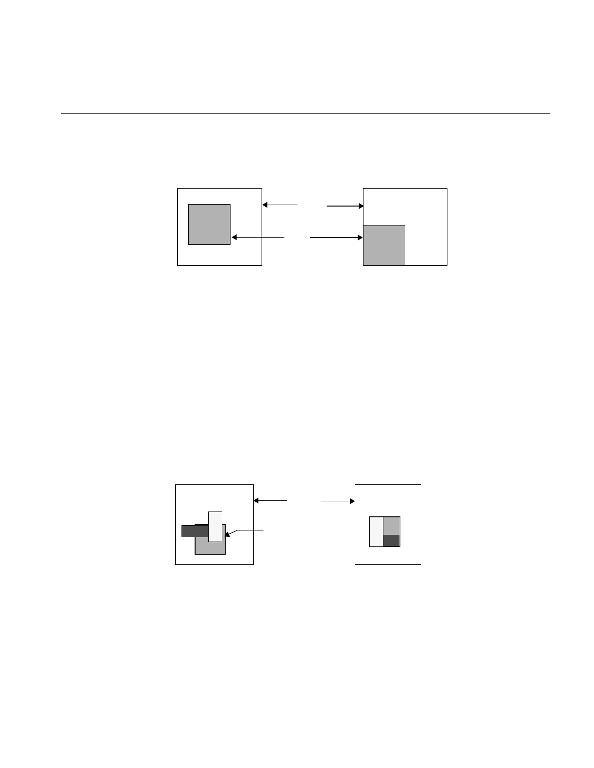
Applying a Display Operator
189
Figure 5-6, ilBottomLeft is passed in mode, causing the lower left corner of the image to
be aligned to the lower left corner of the view.
Figure 5-6 Aligning an Image to Bottom Left Corner
alignView()
The alignView() function is defined on both ilDisplay and ilView. This function aligns
the specified view with a reference view. If NULL is passed, all views are aligned (except
those with the nop flag set). The function is called as shown below:
void alignView(ilView* view = NULL, int mode = ilCenter,
ilView* rView = NULL);
The reference view is specified by rview. If it is NULL, then the back view is used.
Alignment means that edges, corners, or centers of the views are aligned, as shown in
Figure 5-7. The mode argument specifies how to align the views. By default, ilCenter
causes views to be aligned by their centers. In Figure 5-7, the views are aligned by their
lower left corners with ilBottomLeft.
Figure 5-7 Aligning Views
Unaligned Image Aligned Image
Image
View
Unaligned Views Aligned Views
Reference
View
Display

190
Chapter 5: Displaying an Image
moveImg()
The moveImg() function changes the location of images within their respective views. To
use this function, you need to specify the desired location and the view to which the
image corresponds:
void moveImg(float x, float y, ilView* view = NULL,
int mode = ilRelVal);
This function moves the image within the specified view. In other words, the view
remains fixed relative to the display while the corresponding image moves within the
view. This function allows a user to roam around an image. This is particularly useful for
large images that are bigger than the screen. Thus, the coordinate values x,y specify the
desired location of the image’s origin. they are interpreted according to the relevant flags
passed in mode (such as ilDelVal, ilRelVal, and so on). The mode argument can also include
flags indicating that drawing should be deferred (ilDefer) and that the image should not
be moved beyond its edge (ilClip). By default, the image can be moved beyond its view,
in which case the image’s fill value is used to paint the view.
When roam is enabled, the speed with which you can roam around a picture is related to
the displacement of the mouse: the farther you move the mouse, the greater the
displacement between consecutively-displayed frames.
You can change this behavior by calling setRoamLimit(). This function limits the
displacement between consecutively-displayed frames for example, if the limit is set to
four, regardless of how far you move your mouse, consecutively displayed frames will
always be displaced by four pixels. This function has the effect of smoothing out roam
motion.
float getRoamLimit();
void setRoamLimit(float maxRoamDel = 0.0);
void getRoamRate(float& x, float& y);
The getRoamRate() returns the displacement, in pixels, in the X and Y directions
between consecutively-displayed frames.

Applying a Display Operator
191
moveView()
The moveView() function changes the location of views within the display. You might
use this function to allow a user to drag a view around the display area using one of the
mouse buttons. To use this function, specify the desired location and the view to be
moved:
void moveView(int x, int y, ilView* view = NULL,
int mode = ilRelVal);
The view pointer argument view specifies which view to move (or all the views if NULL,
the default). The xand y arguments indicate where to move the view, and mode specifies
how these arguments should be interpreted (with ilDelVal, ilRelVal, and so on).
You can include ilDefer in the mode argument if you do not want the display updated.
Also, by default, you can move the views out of the window. For example, a user can
continue dragging a view past the edge of the window; the view will not be visible, but
ilDisplay keeps track of its location so that if the user drags it in the opposite direction,
eventually the view becomes visible in the window. You can prevent a view from being
moved past the window’s edge by specifying ilClip as part of the mode argument.
split()
The split() function allows you to display all views next to one another in rows and/or
columns rather than randomly overlapping one another. All views are resized and
repositioned based on the number of views in the view stack. Starting at the bottom of
the stack, views are positioned starting at the lower left corner of the display. The split()
function is called as shown below:
void split(int mode = ilAbsSplit|ilRowSplit|ilColSplit)
The mode argument controls the layout. It can be a combination of the following modes:
ilAbsSplit Aligns images to the origin regardless of the view position. (See
Figure 5-8.)
ilRelSplit Positions images relative to view position. (See Figure 5-9.)
ilRowSplit Divides the drawing area into rows. (See Figure 5-8.)
ilColSplit Divides the drawing area into columns.
ilPackSplit Clips views to an image if needed and packs them together.
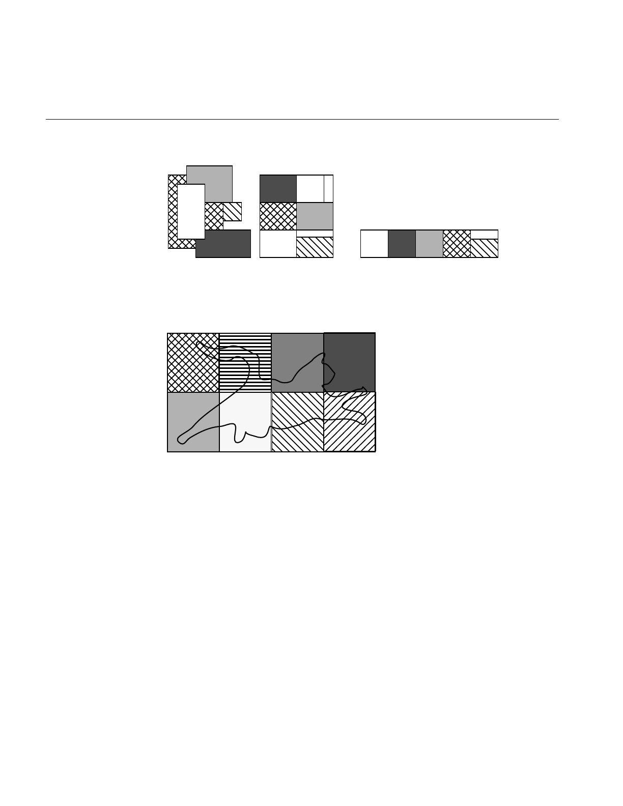
192
Chapter 5: Displaying an Image
Figure 5-8 split() with ilAbsSplit | ilRowSplit | ilColSplit
Figure 5-9 split() with ilRelSplit | ilRowSplit | ilColSplit
If both ilRowSplit and ilColSplit are specified, split() divides the drawing area into
equal-sized rectangles such that the number of rows and columns is nearly equal. (See
Figure 5-9.) Note that if both ilAbsSplit and ilRelSplit are specified, split defaults to
ilAbsSplit. In addition, an alignment mode can be specified with ilAbsSplit, such as
ilCenter.
Displayed with the
default mode ilAbsSplit | Displayed with
iilAbsSplit | ilColSplit
Views to be displayed
ilRowSplit | ilColSplit

Applying a Display Operator
193
Resizing Views
The functions used to resize one or more views are shown below and are described in this
section:
•resize() resizes a view (defined only on ilView).
•wipe() moves one or more edges of a view.
•wipeSplit() wipes the nearest edge of all views.
•wipeSize() wipes an edge or corner and the opposite edge or corner.
As with the relocating functions, if ilAbsVal is passed in mode, the xy values specify the
new size of the view. For ilDelVal, the xy values represent changes to the current size of
the view. ilRelVal means that the xy values are interpreted relative to the start values
previously set with setMouse(). The start values are then updated by ilDisplay unless
ilOldRel is specified.
resize()
The resize() function reinitializes the size of a view to the size of the image it displays.
This useful after setting the image in ilView. The resize() function is called as shown
below:
void resize(int mode = 0);
If ilClip is passed in mode, then the view is clipped to the size of the display. After the
view is resized, it is painted unless ilDefer is passed.
wipe()
The wipe() function moves one or more edges on the specified view. It is called as shown
below:
void wipe(int x, int y, ilView* view = NULL,
int mode = ilRelVal);
The values x and y specify how to move the specified edge of the view. they are
interpreted according to the flags passed in mode (such as ilRelVal, ilDelVal, and so on).
The default is ilRelVal. If NULL is passed for view, then all views are wiped (except those
with nop flag set).

194
Chapter 5: Displaying an Image
The edge to wipe is specified in mode. Any combination of the following edge modes can
be used: ilRightEdge, ilLeftEdge, ilTopEdge, or ilBottomEdge. For example,
ilTopEdge|ilRightEdge (or ilTopRight) allows the user to wipe the upper right corner,
thus resizing the view. In addition, the value returned by findEdge() can be used directly.
(See “Finding an Edge” on page 181.)
If ilAllEdge (or a bitwise OR of all four edges) is used, the effect is slightly different from
a normal wipe. In this mode, called an inset, the view moves while the image remains
fixed (opposite of moveImg()). This mode is useful to move a processed view of an image
around on top of the original image for comparison.
By default, the view is painted after it is wiped unless ilDefer is passed in mode. Also by
default, the edge of a view can be moved beyond the edge of the image, unless ilClip is
passed. When the view is allowed to be wiped beyond the edge of the image, the image’s
fill value is used to paint the exposed region. Note that the wipe function is optimized to
paint only the wiped region.
wipeSplit()
The wipeSplit() function is used in conjunction with findEdge() on ilDisplay to wipe the
nearest edge of all views. It is called as shown below:
void wipeSplit(int x, int y, int mode = ilRelVal);
The x and y parameters control how the edges are moved. No view is specified because
it operates on all views in the view stack. The mode parameter specifies only how to
interpret x and y. Note that the edge on each view is not specified by mode. Instead,
findEdge() must be called on ilDisplay first to find the edge on all views. If no edge is
found for a particular view, then that view is not wiped.
This function is useful after a split operation. For example, if the display is split to show
two views side by side, it allows you to wipe the right edge of the left view and the left
edge of the right view simultaneously. This is useful when comparing two or more
images. In general, adjacent views can be wiped using this function.
wipeSize()
The wipeSize() function wipes the specified edge and the opposite edge to resize the
view. It is called as shown below:
void wipeSize(int x, int y, ilView* view = NULL,
int mode = ilDelVal | ilTopRight);
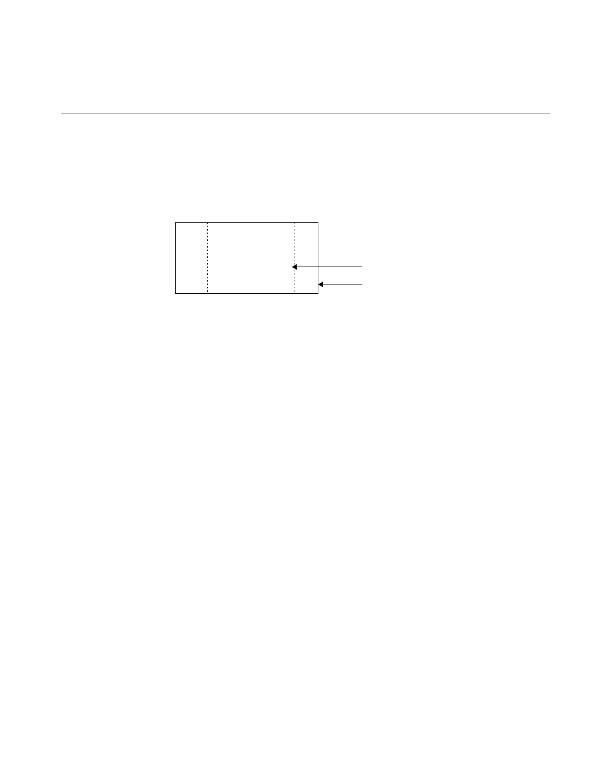
Applying a Display Operator
195
The x and y parameters control which way to move the edge specified in mode. In
addition, the opposite edge is moved in the opposite direction, causing the view to grow
or shrink in size. For example, if the right edge is moved to the right, then the left edge
is moved to the left as well. In this case, the view would grow in width, as show in
Figure 5-10.
Figure 5-10 Using wipeSize()
Updating Views
The update() function can change the view position, view size, and image position as
shown below:
void update(int x=0, int y=0, int nx=0, int ny=0,
int imgX=0, int imgY=0,
ilView* view=NULL, int mode=ilRelVal);
The view is moved to the position specified by x and y and is resized to nx and ny. The
image within the view is moved to the position specified by imgX and imgY. If view is
NULL, then all views in the view stack are updated (except those with nop flag set).
The first six of these parameters are interpreted as specified by mode. For example, if
ilDelVal is specified, then all six parameters are interpreted as changes from the current
configuration. In addition, the parameters are used as specified. However, if ilClip is
passed in mode, then the view position, size, and image position are clipped. After the
view has been updated, it is painted unless ilDefer is passed in mode. The update function
combines the functionality of moveView(),wipe(), and moveImg().
New wiped size of view
Previous size of view

196
Chapter 5: Displaying an Image
Using setMouse()
A display support function that you might find useful as you apply display operators is
setMouse():
void setMouse(int x, int y, int mode = 0);
This function is typically used in an interactive loop to initialize the starting xand y
coordinate values that the ilDisplay keeps track of. The coordinates passed to any
function with ilRelVal or ilOldRel are interpreted relative to the current mouse position.
If ilRelVal is specified, the old start values are updated; however, if ilOldRel is specified,
the start values are not updated. This is useful if several operations are needed and you
do not want to update the start values until you are finished. This model is used in the
program presented in “A Simple Interactive Display Program” on page 165. To retrieve
the previously set start values, use getMouse(). This function returns the start values by
reference:
void getMouse(int& x, int& y);
You can achieve many different effects by judiciously deferring drawing while you apply
a combination of these and/or any of the other display operators.
A More Complicated Interactive Display Program
The ilview interactive display program (which is installed in /usr/sbin when you install
the Image Tools) allows a user to drag, roam, and wipe several images in a display
window. (See ilview’s reference page for more information.) A simplified version of
ilview’s source code is provided online in:
/usr/share/src/il/ilview.c++
The C version of this program named ilcview.c is located in the same directory.
Example 5-2 shows the portion of this program that processes events and calls display
operators. It uses an ilViewer to handle events. The ilViewer class is a higher-level object
derived from ilDisplay. It calls ilDisplay functions and operators based on X events. It
calls moveView() for left mouse button movement and moveImg() for middle mouse
button movement. The cursor changes shape near the edges and corners to indicate that
wipe mode is enabled on the left mouse button. If you press the left mouse button and
perform a wipe, this changed cursor remains for the duration of the wipe. See the
ilViewer reference page and the header file il/ilViewer.h for details.

A More Complicated Interactive Display Program
197
Example 5-2 A More Complicated Interactive Display Program
// Create X window viewer
ilViewer viewer(dpy, winsize.x, winsize.y, attr);
for (idx = 0; idx < nimg; idx++)
viewer.addView(img[idx], ilLast, ilClip|ilCenter|ilDefer);
viewer.setStop(TRUE);
// Execute the UI event loop
// XXX need event call back on ilViewer to make this easier to do
int done=FALSE;
while (!done) {
XEvent e;
XNextEvent(dpy, &e);
switch (e.type) {
case KeyPress:
switch(XLookupKeysym(&e.xkey, 0)) {
// center the selected view(s) in the viewer
case XK_Home:
viewer.display(NULL, ilCenter|ilClip);
break;
// control-Q and escape exit the program
case XK_q:
if (!(e.xkey.state&ControlMask))
break;
/*FALLTHROUGH*/
case XK_Escape:
done = TRUE;
break;
// raise and lower the current view(s)
case XK_Up:
viewer.raise();
break;
case XK_Down:
viewer.lower();
break;
// enable/disable paint pipelining
case XK_p:

198
Chapter 5: Displaying an Image
viewer.enableQueueing(!viewer.isQueueingEnabled());
break;
}
break;
case DestroyNotify:
viewer.destroyNotify();
done = TRUE;
break;
default:
viewer.event(&e);
break;
}
}
exit(EXIT_SUCCESS);
}

199
Chapter 6
6. Extending ImageVision Library
Since ImageVision Library (IL) is implemented in C++, you can easily extend it by
deriving new classes that provide support for the capabilities you need; for instance, to
include another file format or image processing algorithm. You can derive from any C++
class, but you are most likely to want to derive from the foundation classes. Figure 6-1
shows the types of classes you are most likely to derive.
Note: If you are using the C interface to IL, extending the library is not quite so simple.
You have to implement a new class in C++ and then generate a C interface for it.
This chapter contains the following major sections:
•“Deriving From ilImage” on page 202 tells you how to derive new classes from
ilImage.
•“Deriving From ilCacheImg” on page 212 tells you how to derive new caching
classes to manage data.
•“Deriving From ilMemCacheImg” on page 213 tells you how you can derive from
ilMemCacheImg to manage images in main memory.
•“Implementing an Image Processing Operator” on page 215 tells you how to define
operators that implement new image processing algorithms.
•“Deriving From ilRoi” on page 242 describes how you define new regions of
interest in your images.
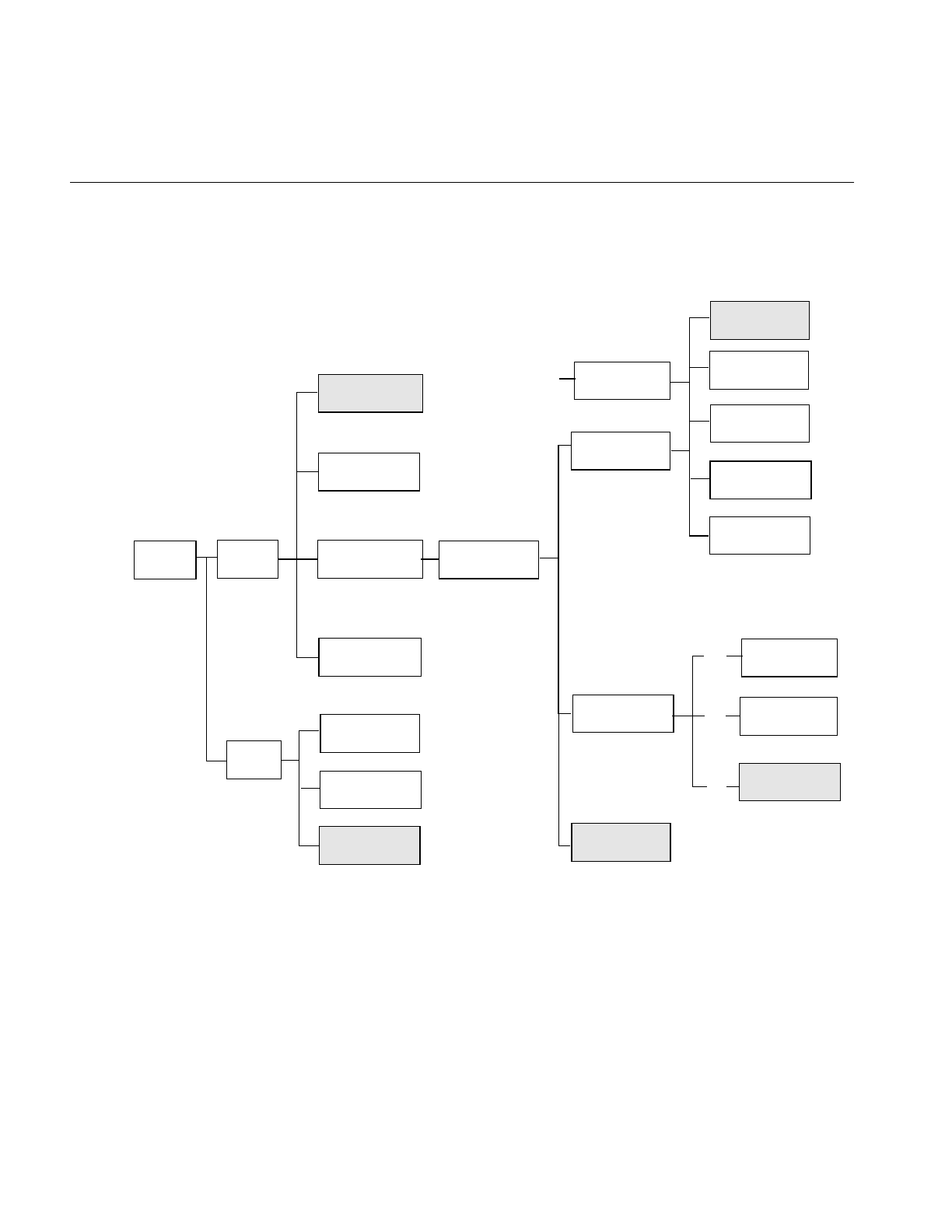
200
Chapter 6: Extending ImageVision Library
IL classes from which you might want to derive your own new classes are shown in
Figure 6-1.
Figure 6-1 User-Defined Classes in IL
Each extension to IL can be designed to provide a certain set of capabilities and require
the implementation of a matching set of functions, as described below:
•newImgClass—A class derived from ilImage inherits all of its functions for
handling an image’s attributes; it needs to implement ilImage’s pure virtual
ilImage
ilFrameBufferImg ilSharpenImg
ilRotZoomImg
ilOpImg
ilCacheImg
ilFileImg
. .
newCacheClass
newOperator
newImgClass
ilLink
ilMemoryImg
ilImgRoi
newRoiClass
ilRectRoi
ilRoi
ilMemCacheImg
. .
. .
ilImgRoi
newRoiClass
ilRectRoi
iflJFIFFILE
IFLrAWfILE
IFLfitfILE
iflTIFFFile
newFileFormat
iflFormat
. .

201
functions for reading and writing data. More information on deriving from ilImage
is provided in “Deriving From ilImage” on page 202.
•newCacheClass—A class derived from ilCacheImg inherits its caching mechanism;
such a class is useful for managing a large amount of data that is accessed a portion
at a time. More information on deriving from ilCacheImg is provided in “Deriving
From ilCacheImg” on page 212.
•new ilMemCacheImg class—A class derived from ilMemCacheImg inherits its main
memory caching mechanism. Implement the pure virtual functions for storing and
retrieving pages of image data. More information on deriving from
ilMemCacheImg is provided in “Deriving From ilMemCacheImg” on page 213.
•newOperator—To define a new operator, you need to implement the desired image
processing algorithm and ensure that the processed image has the correct attributes.
You can derive directly from ilOpImg or from one of its generalized subclasses. See
“Implementing an Image Processing Operator” on page 215 for more information.
•newRoi—To define a new region of interest (ROI), you need to derive from ilRoi
and implement functions that describe valid and invalid regions with respect to this
new ROI. See “Deriving From ilRoi” on page 242 for more information.
The classes ilImage, ilCacheImg, ilMemCacheImg, ilOpImg, and ilRoi declare virtual
functions that subclasses may be redefined to alter class behavior. Other functions can be
added as necessary to provide the desired capabilities of the class.
The remaining sections in this chapter explain how to derive from ilImage, ilCacheImg,
ilMemCacheImg, iflFileImg, ilOpImg, or ilRoi (or one of their generalized subclasses).
Remember that when you derive from a class, you inherit all its public and protected
data members and member functions, as well as the public and protected members from
its superclasses. You should review beforehand the header files and the reference pages
for any class you plan to derive from in order to become familiar with its data members
and member functions. Many of the functions described in the following sections are
protected, so they are available for use only by derived classes.

202
Chapter 6: Extending ImageVision Library
Deriving From ilImage
A class derived from ilImage must assign values to the image’s attributes and implement
ilImage’s virtual functions. The image’s attributes (data members) are listed in Table 6-1;
they are generally initialized in the constructor.
Typically, you will just set these attributes directly. However, there are convenience
functions—for setting minValue,maxValue,cm, and status—that you might want to use
(these functions are protected, so they are available only to classes derived from ilImage):
void initMinMax(int force=FALSE);
void initColorModel(int noAlpha=FALSE);
void initPagesize(const iflSize& pageSize);
ilStatus setStatus(ilStatus val); //inherited from ilLink
void clearStatus(); // inherited from ilLink
The initMinMax() function simultaneously sets both the minimum and maximum
allowable pixel values. They are set to the smallest and largest possible values,
respectively, allowed by the image’s data type. Therefore, you must set the image’s data
type before you call initMinMax(). By default, this function’s argument is FALSE, which
means that the minimum and maximum values will not be changed if they have already
a. Inherited from ilLink.
Table 6-1 Image Attributes Needing Initialization in ilImage Subclass
Name Data Type Meaning
pageSize iflSize size of the image’s pages in pixels
dtype iflDataType pixel data type
order iflOrder pixel data ordering
cm iflColorModel image’s color model
orientation iflOrientation location of origin and orientation of axes
fillValue iflPixel value used to fill pixels beyond the image’s edge
minValue,
maxValue
double minimum and maximum allowable pixel values
status ilStatus image’s status (for example, ilOKAY)a

Deriving From ilImage
203
been explicitly set; if you pass in TRUE as the argument to this function, both values will
be set regardless of whether they have been set before.
The initColorModel() function sets the color model based on the channel dimension of
the image. If the channel dimension is 1, the color model is iflLuminance; if it is 2, the
color model is iflLuminanceAlpha (or iflultiSpectral if noAlpha is TRUE); if it is 3, the
color model is iflRGB. If the channel dimension is 4 and the default value of FALSE is
used for the noAlpha argument, the color model is iflRGBA. Otherwise, the color model
is iflMultiSpectral.
The setStatus() function simply sets and returns the image’s status. The clearStatus()
function sets the image’s status to ilOKAY. (Both of these functions are inherited from
ilLink.) See “Error Codes” on page 366 for a list of the error codes that IL defines as being
of type ilStatus.
Another function you may want to use in a constructor is setNumInputs(). This function
sets the maximum possible number of inputs to an image. Typically, you will use this
function only when deriving an operator. See “Implementing an Image Processing
Operator” on page 215 for more information about doing this.
Data Access Functions
Image data can be accessed as pixels or as a rectangular region of arbitrary size called a
tile. Both 2-D and 3-D tile access functions are provided.
The virtual access functions present a queued request model, which allows an
application to issue non-blocking requests for image I/O and later inquire the status or
wait for the operation to complete. The queued model also provides derived classes with
the “hooks” needed to automatically distribute operations across multiple processors.
These queued functions are distinguished by the prefix “q” on the function name. For
convenience, there are access functions that do wait for their operation to complete,
hiding the details of the queued model.
There are several different functions to read image data, all based on qGetSubTile3D().
ilQGetSubTile3D(). Similarly, there are several different functions to write image data
based on qSetSubTile3D(). ilQSetSubTile3D(). Two fast-paths called qCopyTileCfg() and
qCopyTile3D() ilQCopyTileCfg() and ilQCopyTile3D() are available for copying a tile
from another ilImage.

204
Chapter 6: Extending ImageVision Library
Most of the virtual functions in ilImage are data access functions:
virtual ilStatus qGetSubTile3D(ilMpNode* parent, int x, int y, int z,
int nx, int ny, int nz, void*& data, int dx, int dy, int dz, int dnx,
int dny, int dnz,const ilConfig* config=NULL, ilMpManager** pMgr=NULL);
virtual ilStatus qSetSubTile3D(ilMpNode* parent, int x, int y, int z,
int nx, int ny, int nz, void* data, int dx, int dy, int dz, int dnx,
int dny, int dnz, const ilConfig* config=NULL, ilMpManager** pMgr=NULL);
virtual ilStatus qCopyTileCfg(ilMpNode* parent, int x, int y, int z,
int nx, int ny, int nz, ilImage* other, int ox, int oy, int oz,
const ilConfig* config=NULL, ilMpManager** pMgr=NULL);
virtual ilStatus qDrawTile(ilMpNode* parent, int x, int y, int nx, int ny,
ilImage* src, float sx, float sy, float sz, ilMpManager** pMgr=NULL);
virtual ilStatus qFillTile3D(ilMpNode* parent, int x, int y, int z,
int nx, int ny, int nz, const void* data, const ilConfig* config=NULL,
const iflTile3Dint* fillMask=NULL, ilMpManager** pMgr=NULL);
virtual ilStatus qFillTileRGB(ilMpNode* parent, int x, int y, int z,
int nx, int ny, int nz, float red, float green, float blue,
const iflTile3Dint* fillMask=NULL,
iflOrientation orientation=iflOrientation(0), ilMpManager** pMgr=NULL);
virtual ilStatus qLockPageSet(ilMpNode* parent, ilLockRequest* set,
int mode=ilLMread, int count=1, ilMpManager** pMgr=NULL,
ilCallback* perPageCb=NULL);
ilStatus qGetTile3D(ilMpNode* parent, int x, int y, int z, int nx, int ny,
int nz, void*& data, const ilConfig* config=NULL, ilMpManager** pMgr=NULL)
ilStatus qSetTile3D(ilMpNode* parent, int x, int y, int z, int nx, int ny,
int nz, void* data, const ilConfig* config=NULL, ilMpManager** pMgr=NULL)
When calling the base functions listed above, the caller must specify the origin (x, y, z)
and size (nx, ny, nz) of the desired tile. For 2-D operations, z is set to 0 and nz is set to 1.
For pixel operations, nx, ny and nz are set to 1. An object called iflConfig, is used to
specify the configuration (that is, data type, order, number of channels and so forth) of
the desired tile. If required, the image data is converted to a specified configuration while
getting a tile, or converted from a specified configuration to that of the image while
setting a tile.

Deriving From ilImage
205
All of these functions have default implementations that you can choose to override. The
rest of this section explains how to implement these functions.
Implementing qGetSubTile3D()
You should implement qGetSubTile3D() so that it retrieves an arbitrary tile of data from
the source image and puts it into the location indicated by data. The tile is located at
position (x, y, z) in the source image and has the size indicated by nx,ny, and nz. The dx,
dy, and dz parameters specify the data buffer’s origin relative to the image; dnx,dny, and
dnz specify the buffer’s size. The optional config argument indicates how the data should
be configured in the buffer. See “Three-dimensional Functions” on page 46 for more
information about qGetSubTile3D().
This function has a default implementation that returns ilUNSUPPORTED.
Implementing qSetSubTile3D()
Your version of the qSetSubTile3D() function should write the tile of data pointed to by
data into the destination image. The arguments for qSetSubTile3D() have analogous
meanings to those for qGetSubTile3D(): (x,y,z) and (nx, ny, nz) indicate the desired
origin and size of the tile in the destination image; dx,dy, and dz specify the data buffer’s
origin relative to the image; and dnx,dny, and dnz specify the size of the data buffer. The
optional config argument describes the configuration of the tile being passed or written;
if it is NULL, assume that the tile’s configuration matches that of the destination image.
See “Three-dimensional Functions” on page 46 for more information about
qSetSubTile3D().
This function has a default implementation that returns ilUNSUPPORTED.
Implementing qCopyTileCfg()
The default implementation of qCopyTileCfg() copies a tile of data from one image to
another. This implementation is not as efficient as possible, since it allocates a temporary
buffer for holding the data as it performs the copy and then deletes the buffer when it
completes the copy. You might want to override this function to provide a more efficient
version.

206
Chapter 6: Extending ImageVision Library
Implementing qFillTile3D() and qFillTileRGB()
The default versions of qFillTile3D() and qFillTileRGB() do nothing; you will need to
override them if you want their functionality. Your implementations should fill a
specified tile with the specified pixel value or color.
Implementing qLockPageSet()
Your implementation of qLockPageSet() should set a read-only lock for a set of pages
when accessing image data. A pointer to each page in the set is deposited in each
corresponding ilLockRequest. As a result, the image data for all of the pages is
computed. If all of the requests succeed, ilOKAY is returned. If one or more fail, an error
code will be returned and the ilLockRequest structures will contain individual status
codes.
Implementing qGetTile3D()
This function places the destination of a tile, pointed at by data, at coordinates, x, y, z
using the size of the source image defined by dx, dy, dz.
Your class must overwrite qGetTile3D(). Its default function returns ilUNSUPPORTED.
Implementing qSetTile3D()
This function allows the source buffer to have a different position and size, specified by
dx,dy,dnx,dny,dz, and dnz.
Your class must overwrite qGetTile3D(). Its default function returns ilUNSUPPORTED.
Support Functions
The outOfBound() support functions are provided to help implement the data access
functions:
int outOfBound(int x, int y);
int outOfBound(int x, int y, int z);
These functions return TRUE if the specified point lies outside the image.
If you implement any of the data access functions, you need to hook them into the reset
mechanism, which is described next.

Deriving From ilImage
207
Color Conversion
The checkColorModel() function matches the color model of an image with the number
of channels. If there is a mismatch, the number of channels is updated to match the color
model. However, if the number of channels was set and there is a mismatch, a status of
ilBADCOLFMT is set.
void checkColorModel();
The needColorConv() function returns TRUE if the image’s color model does not match
the color model of other. The from flag indicates the direction that data is copied:
needColorConv(ilImage* other, int from, const ilConfig* cfg);
The getCopyConverter() function chains one image to another provided the two images
have different color models. If the images have the same color model, there is no color
conversion. getCopyConverter() is defined as follows:
int getCopyConverter(ilImage*& other,const ilConfig* cfg)
The getCopyConverter() function returns TRUE if the other image has a different color
model than this image. In this case, a color converter operator is chained onto the other
image.
The getCopyConverter() function returns FALSE if the color models are compatible, or
if the cfg specifies a channel list or channel offset. In this case a converter operator is not
chained to the other image.When cfg specifies a channel list or offset, no color conversion
is performed.
Managing Image Attributes
An image has numerous attributes associated with it that describe the image. You can
change some attributes; some change as a side effect of changing some other attribute.
This section describes functions you can use to manage attribute values in a class derived
from ilImage.

208
Chapter 6: Extending ImageVision Library
The reset() Function
An important virtual function in ilImage that you must be concerned with is reset():
virtual void reset(); // inherited from ilLink
This function is designed to adjust or validate an image’s attributes if they have been
altered, for example, by applying an operator or by setting an attribute explicitly. This
function plays a key role in IL’s execution model, which propagates image attribute
values down an operator chain. (See “Propagating Image Attributes” on page 59 for
more information on propagating image attributes.)
The reset mechanism is triggered whenever an image is queried about its attributes or
when its data is accessed. The query and access functions all call resetCheck() (which is
inherited from ilLink) to initiate the reset process. If you implement qGetSubTile3D(),
qSetSubTile3D(), qCopyTileCfg(),qFillTile3D(),qFillTileRGB(),qLockPageSet(),
qGetTile3D(),qSetTile3D() or any attribute query, you need to call resetCheck() before
you do anything else in your versions of these functions. This ensures that correct
information about an image’s attributes is returned and that image data is always valid
before it is read, written, copied, filled, or updated.
The reset() function must be defined by derived classes to perform any necessary reset
tasks. For example, the ilMemCacheImg class’s version of reset() throws out any existing
data in the cache since it is invalid; ilOpImg performs several chores in its reset() function
and then calls resetOp(), which needs to be implemented by derived classes to perform
more specific reset tasks.
Allowing Attributes to Change
Not every image attribute can be changed; by default, the fill value and the maximum
and minimum pixel values are allowed to change. Each ilImage derived class can choose
which attributes it allows to be modified by using the setAllowed() function (inherited
from ilLink), typically in the constructor:
setAllowed(ilIPcolorModel|ilIPorientation);
The argument passed to setAllowed() is a mask composed of a logical combination of the
enumerated type, ilImgParam, which is defined in the header file il/ilImage.h. The
ilImgParam constants defined in IL are listed in Table 6-2. Each image attribute listed in
the table is described elsewhere in this guide. Derived classes can add members to this

Deriving From ilImage
209
structure to trace whether particular parameter values have changed and to control
whether they can be explicitly modified.
Table 6-2 ilImgParam Constants
Defining Class ilImgParam Image Attribute
ilImage ilIPdataType data type
“ilIPorder pixel ordering
“ilIPpageSize page size
“ilIPxsize x dimension of page size
“ilIPysize y dimension of page size
“ilIPzPageSize z dimension of page size
“ilIPxyPageSize x,y dimension of page size
“ilIPcPageSize component value of a pixel
“ilIPpageSize red values of ilIPzPageSize,
ilIPxyPageSize, and ilIPcPageSize
“ilIPchans number of channels
“ilIPdepth z dimension of the image
“ilIPorientation orientation
“ilIPcolorModel color model
“ilIPminValue minimum pixel value
“ilIPmaxValue maximum pixel value
“ilIPscale color scaling value
“ilIPfill fill value
“ilIPcompression compression
“ilIPcmap look-up table color map
“ilIPpageBorder page border for overlapping pages
ilFileImg ilFPimageIdx image index

210
Chapter 6: Extending ImageVision Library
Preventing Attributes From Changing
An image can explicitly disallow any of these attributes to be modified. For this, it uses
the clearAllowed() function (from ilLink) and passes in a logical combination of the
ilImgParam parameters that should be disallowed.
Another function, isAllowed() (inherited from ilLink), checks whether a particular
attribute can be modified:
canChange = myImg.isAllowed(ilIPsize);
This function takes the same sort of argument as clearAllowed() and returns TRUE if the
attributes specified are not allowed to be modified.
Setting Altered and Stuck Flags
When an attribute’s value is changed by the user (by calling the appropriate attribute
setting function), setAltered() (from ilLink) should be called to set a flag indicating that
a reset is needed. Thus, you must call setAltered() within any attribute setting functions
you define. This function takes a mask of ilImgParam parameters as an argument and
sets the altered flags for the specified attributes.
You can check whether any particular attributes have been altered with isAltered()
(inherited from ilLink). This function takes an ilImgParam mask as an argument and
returns TRUE if any of the specified attributes have been altered.
As explained in “Propagating Image Attributes” on page 59, IL programs need to keep
track of attributes that have been explicitly set by the user so that they remain fixed
ilOpImg ilIPbias bias value
“ilIPclamp clamp value
“ilIPworkingType working data type
ilSubImg ilIPconfig configuration
ilImgStat ilISPzBounds z dimension bounds
ilRoi ilROIorientation orientation
Table 6-2 (continued) ilImgParam Constants
Defining Class ilImgParam Image Attribute

Deriving From ilImage
211
during the reset process. To keep track of these attributes, you should call markSet()
(inherited from ilLink) with an ilImgParam mask as an argument. This function marks
the specified attributes with a stuck flag (yet another item inherited from the ilLink class),
which indicates that their values should not be changed during a reset operation.
markSet() is invoked automatically for you when setAltered() is called, so generally you
do not need to call markSet() yourself.
You can determine whether any attributes are fixed with isSet() (inherited from ilLink).
This function returns TRUE if any of the attributes specified in the mask passed in have
been explicitly set.
Setting Attributes Directly
Sometimes within a derived class’s implementation, you may want to change an
attribute’s value without triggering the reset mechanism and without causing the value
to become fixed. You have already seen one situation where you want to do this: within
a constructor, when attributes are being initialized. Another case is when you are
computing attribute values during the reset operation itself. In these situations, you do
not use a attribute setting function since it calls setAltered(), which in turn calls
markSet(). Since derived classes have access to protected data members, simply set the
value of the desired attribute directly:
dtype = iflFloat; // changes value; no flag set
The initMinMax(),initColorModel(), and setStatus() functions described earlier in this
section all set attributes directly.
Adding New Attributes
It is quite easy to add attributes to a newly derived class. You can use the header files for
the already existing IL classes for examples. This an example is from the il/ilOpImg.h
header file:
enum ilOpImgParam {
ilIPbias = ilImgParamLast<<1,
ilIPclamp = ilImgParamLast<<2,
ilIPworkingType = ilImgParamLast<<3,
ilOpImgParamLast = ilIPworkingType
};

212
Chapter 6: Extending ImageVision Library
The pattern is simple. Suppose you were to derive a new class from ilOpImg and add
parameters to it. You might do the following:
enum ilMyClassParam {
ilIPparam1 = ilOpImgParamLast<<1,
ilIPparam2 = ilOpImgParamLast<<2,
ilIPparam5 = ilOpImgParamLast<<5,
ilMyClassParamLast = ilIPparam5
};
Deriving From ilCacheImg
The ilCacheImg class implements an abstract model of cached image data. The main
purpose of this class is the definition of a common API for cached image objects. You can
implement your own caching mechanism by deriving from ilCacheImg. The
ilMemCacheImg class, derived from ilCacheImg, provides an example of the
implementation of a caching mechanism.
If you derive from ilCacheImg, you must implement the data access methods inherited
from ilImage. You must also implement the flush(),getCacheSize(), and listResident()
functions if you derive from ilCacheImg.
The flush() function causes any modified data in the cache to be written out. Derived
classes that access an image file can call this function in their destructor before they close
the file to ensure that all data is written:
virtual ilStatus flush(int discard=FALSE);
The getCacheSize() function returns the amount of cache memory, in bytes, currently
allocated by this image object:
virtual size_tgetCacheSize();
The listResident() function returns a list of all the resident pages:
virtual ilStatus listResident(ilCallback* cb);
The callback specified in cb is invoked once for each page resident in memory. The
callback function should have prototype as defined in addPagingCallback().

Deriving From ilMemCacheImg
213
Deriving From ilMemCacheImg
The ilMemCacheImg class implements a caching mechanism for efficiently manipulating
image data in main memory. In managing the interface to an image’s cache,
ilMemCacheImg implements all of the ilImage virtual data access functions. The
ilMemCacheImg class also implements the virtual function hasPages(), which is defined
in ilImage. hasPages() should return TRUE only for classes that implement IL’s paging
mechanism (ilMemCacheImg does).
Classes that derive from ilMemCacheImg do not need to implement these functions;
instead, they need to implement some or all of the following virtual functions:
virtual ilStatus prepareRequest(ilMpCacheRequest* req);
virtual ilStatus executeRequest(ilMpCacheRequest* req);
virtual ilStatus finishRequest(ilMpCacheRequest* req);
virtual ilStatus getPage(ilMpCacheRequest* req);
virtual ilStatus setPage(ilMpCacheRequest* req);
Image data requests are processed through the multi-processing scheme defined by the
ilMpManager and ilMpRequest classes. The virtual functions, prepareRequest(),
executeRequest(), and finishRequest(), define the API for multi-processing. To maintain
the multi-processing scheme, you must sub-divide processing operations into these three
stages:
•prepareRequest() allocates buffer space for the pages an operator will work on and
loads the image data from those pages into the buffer.
•executeRequest() performs the image manipulation on the pages in the buffer.
•finishRequest() deallocates the buffer space allocated in prepareRequest() and
unlocks the input pages.
Derived classes must re-define these virtual functions. These functions are described in
greater detail in “Handling Image Processing” on page 221.
The ilMpCacheRequest class (defined in the header file il/ilMemCacheImg.h) defines the
page’s location within the image and the amount of data to be processed:
class ilMpCacheRequest : public ilMpRequest, public iflXYZCint {
public:
ilMpCacheRequest(ilMpManager* parent, int x, int y, int z, int c,
int mode = ilLMread);

214
Chapter 6: Extending ImageVision Library
// methods to access mode fields
int isRead() { return mode&ilLMread; }
int isWrite() { return mode&ilLMwrite; }
int isSeek() { return mode&ilLMseek; }
int getPriority() { return mode&ilLMpriority; }
// method to access page data
void* getData() { return page->getData(); }
int nx, ny, nz, nc; // size of valid data in page
};
Since an image’s size is not generally an exact multiple of the page size, you are likely to
encounter pages that are only partially full of data. The nx, ny, nz, and nc members define
the actual limits of the data that you need to read or write within a given page buffer. You
might want to use the getStrides() function to help you step through a page buffer. See
“Data Access Support Functions” on page 47 for more information about getStrides().
Table 6-3 lists additional attributes you might need to initialize for a class derived from
ilMemCacheImg.
You can also implement the allocPage() and freePage() functions. These functions
allocate or free a page in main memory whose pixel includes (x,y,z,c). If you implement
the function allocPage(), you must also call the function doUserPageAlloc() in the
function that calls allocPage() to notify IL that the pages need to be defined.
The flush() function (defined by ilMemCacheImg) flushes data from an image’s cache; it
calls setPage() to ensure that the data is written to the proper place:
virtual ilStatus flush(int discard=FALSE);
Table 6-3 Additional Attributes Needing Initialization in ilMemCacheImg Derived Classes
Name Data Type Meaning
pageSizeBytes size_t size of a page in bytes
pageSize iflSize pixel dimensions of the pages used to store data on
disk
pageBorder iflXYZint pixel dimensions of page borders as stored on disk
(default is zero)

Implementing an Image Processing Operator
215
This function takes one optional argument and returns an ilStatus to indicate whether the
flush was successful. Calling flush() with a TRUE argument discards all data in the cache.
This is useful for freeing up memory if you know you are never going to use the cached
data again. When discard is FALSE, flush() writes any modified data from the cache to
the image. The destructor for any class derived from ilMemCacheImg may need to call
ilMemCacheImg’sflush() (with discard equal to FALSE) before the class object is deleted
to ensure that any modified data is written back to the image.
For more information about deriving from either of ilMemCacheImg’s derived class
ilOpImg, see “Implementing an Image Processing Operator” on page 215.
Implementing an Image Processing Operator
IL is designed to be easily extendable in C++ to include image processing algorithms you
implement. You can derive a new operator directly from ilOpImg, or you can take
advantage of the support provided by its subclasses, some of which are specifically
designed to be derived from. This section explains in detail how to derive your own
operator. It contains these sections:
•“Deriving From ilOpImg” on page 217
•“Deriving From ilMonadicImg or ilPolyadicImg” on page 228
•“Deriving From ilSpatialImg” on page 234
•“Deriving New Classes From ilWarpImg and ilWarp” on page 237
•“Deriving From ilFMonadicImg or ilFDyadicImg” on page 238
•“Deriving From ilFFiltImg” on page 241
The subclasses of ilOpImg handle the tasks of reading raw data from the cache and
writing processed data back to the cache; if you derive from these classes, you are
responsible for writing only the function that processes the data in a given input buffer
and writes it to a given output buffer. If you derive directly from ilOpImg, you need to
supply your own interface to the cache as well as your processing algorithm. Figure 6-2
shows the operator classes you are most likely to derive from.
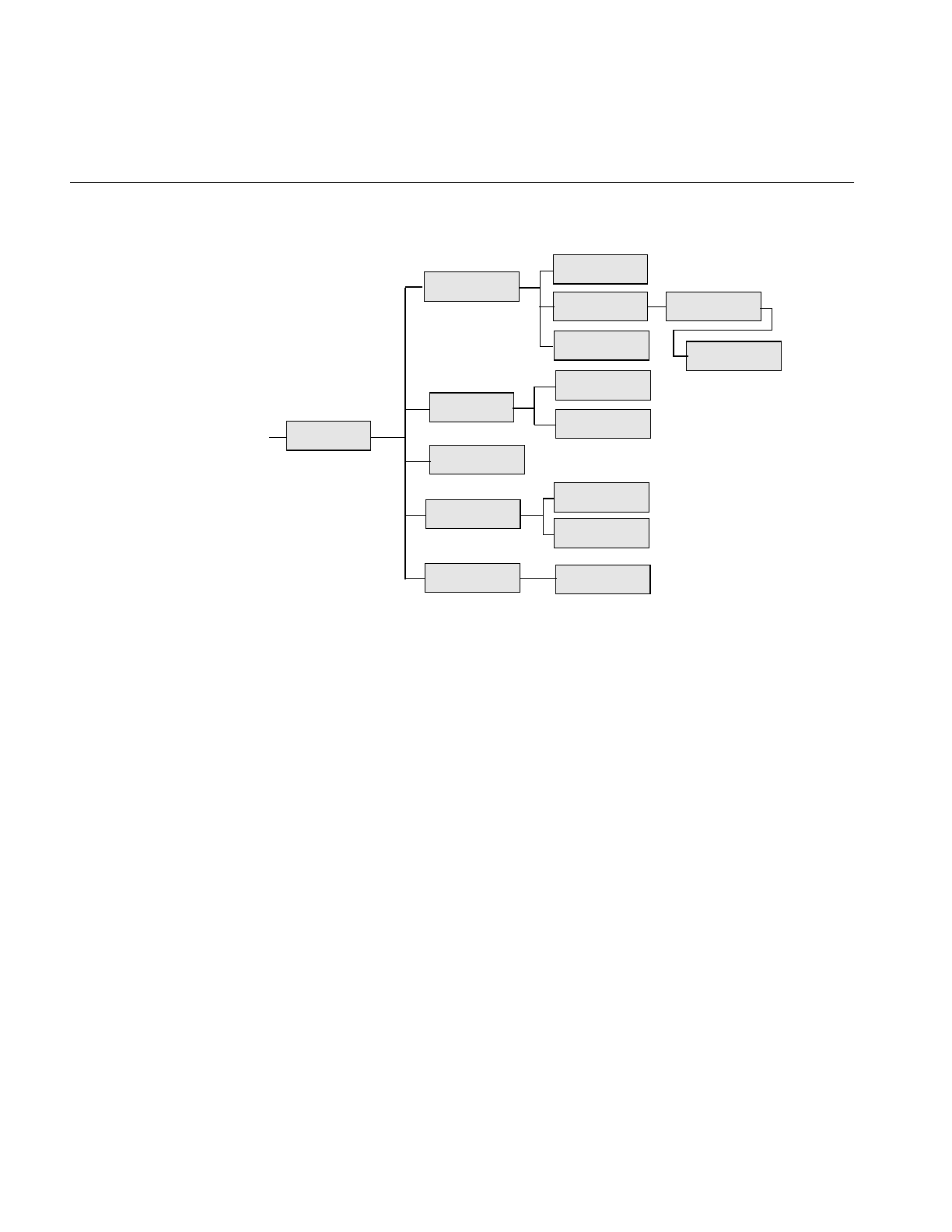
216
Chapter 6: Extending ImageVision Library
Figure 6-2 ilOpImg and Its Subclasses for Deriving
Remember that when you derive from a class, you inherit all of its public and protected
data members and member functions. You also inherit members from its superclasses.
You should review the header file and the reference page for any class you plan to derive
from (as well as the header file and reference pages of its superclasses) to become familiar
with its data members and member functions. It is also a good idea to look at a few of its
subclasses to see what general tasks they perform and what functions they implement.
Finally, you might want to take a look at the selected IL source code that is provided
online in /usr/share/src/il/src.
The next section contains information that is useful whether you derive directly from
ilOpImg or from one of its subclasses. The sections that follow contain more detailed
information about deriving from each of ilOpImg’s subclasses shown in Figure 6-2.
ilOpImg
...
ilColorImg
ilFDyadicImg
ilFFiltImg
ilFMonadicImg
ilWarpImg
ilMonadicImg
ilSpatialImg
ilLutImg ilArithLutImg
ilHistLutImg
ilConvImg
ilSepConvImg
ilFPolyadicImg
ilPolyadicImg ilDyadicImg

Implementing an Image Processing Operator
217
Deriving From ilOpImg
A class derived from ilOpImg needs to implement these member functions:
•The constructor, which creates the object, declares which data types and pixel
orders are valid for the output, and sets the working data type.
•resetOp(), which adapts to any attributes that have been altered, such as changing
the input image
•keepPrecision(), which maintains the data type of a returned value.
•prepareRequest(), which queues the data accessed from the input image(s) for a
requested page of the operator. It also allocates the buffer(s) to hold the input image
data.
•executeRequest() which performs the operator’s processing when the input data is
loaded. The result is placed directly in a page of the operator’s cache.
•finishRequest() frees any resources allocated in prepareRequest(). This is separate
from executeRequest() so that aborted operations that have already done
prepareRequest() can clean up without bothering with the work done in
executeRequest().
•Any public setParam() and getParam() parameter set or get functions provided to
control the operator’s algorithm.
You also need to implement a destructor if you allocate any memory or change state
within the constructor or any other function you implement. Example 6-1 shows a
typical header file for an ilOpImg subclass.
Example 6-1 Typical Header for a Class Derived From ilOpImg
#include <il/ilOpImg.h>
class myOperator : public ilOpImg {
public:
myOperator(ilImage* img, float param1);
void setParam1(float val)
{ param1 = val; setAltered(); }
float getParam1()
{ resetCheck(); return param1; }
};
protected:
void resetOp();
ilStatus prepareRequest(ilMpCacheRequest *req);

218
Chapter 6: Extending ImageVision Library
ilStatus executeRequest(ilMpCacheRequest *req);
ilStatus finishRequest(ilMpCacheRequest *req);
private:
float param1;
The resetOp() function should be declared protected if other programmers are likely to
want to derive a class from the myOperator class.
The Constructor
The constructor takes a pointer to the source ilImage(s) and additional arguments as
needed to provide parameters to control the operator’s processing algorithm (for
example, param1). If you do use additional parameters, you might want to define
corresponding functions that allow the user to alter and retrieve the value of those
parameters (such as setParam1() and getParam1()). These functions should probably
take advantage of IL’s reset mechanism by calling setAltered() and resetCheck(),
respectively. (See “The reset() Function” on page 208 for more information about how
IL’s reset mechanism works.) Example 6-2 shows you what a simple constructor might
look like.
Example 6-2 Typical Constructor for a Class Derived From ilOpImg
myOperator::myOperator(ilImage* img=NULL, float param1=Param1Default)
{
setValidType(iflFloat|iflDouble);
setValidOrder(iflInterleaved|iflSequential|iflSeparate);
setWorkingType(iflDouble);
setNumInputs(1);
setInput(img);
setParam1(param1);
}
In this example, myOperator can produce output of either iflFloat or iflDouble data type;
the output has the same pixel ordering as the input image. Input image data that is of
type iflFloat is cast to iflDouble before it is processed; this is the meaning of an operator’s
working type. Some operators can handle multiple inputs, but the setNumInputs()
function is used here to limit myOperator to one input. The setInput() function sets the
input to be the ilImage passed in; this step chains myOperator to the input image. Finally,
param1’s value is initialized.

Implementing an Image Processing Operator
219
The setValidType(),setValidOrder(), and setWorkingType() functions are all defined as
protected in ilOpImg. They are discussed in more detail in ilOpImg’s reference page. The
ilImage class defines setNumInputs() (protected) and setInput().
The constructor should not contain any calculations that are based on the value of
arguments passed in, since these arguments might change. Most operators that require
arguments other than the input image in their constructors define functions for
dynamically changing the value of those arguments (like setParam1()). Such calculations
should be done in the resetOp() function described below. The resetOp() function is
declared in ilOpImg, but its implementation is left to derived operators. Note that when
any ilImage is created, it is considered “altered,” so resetOp() is always called before any
data is computed.
The resetOp() Function
Since resetOp() is guaranteed to be called before prepareRequest(),executeRequest(),
and finishRequest(), it can—and should—be used to calculate the values of variables
needed by these methods, particularly if those variables depend on arguments passed in
the operator’s constructor. The resetOp() function also needs to reset any image
attributes that change as a result of the image’s data being processed, so that the proper
attribute values can be propagated down an operator chain. As an example, imagine an
operator that defined the following variables (probably as protected) in its header file
(ilMonadicImg defines these variables):
iflXYZCint str; // output (page) buffer strides
iflXYZCint istr; // input image strides
int bufferSize; // size of input buffer in bytes
int cBuffSize; // number of channels in input buffer
As you might expect, these variables are used to determine the size of the internal buffer
needed for reading in the image’s data that is to be processed. This buffer is actually
allocated in prepareRequest(), but the values for these variables are calculated in
resetOp(), since they depend on the input image’s page size and data type attributes.
Example 6-3 illustrates this with ilMonadicImg’s implementation of resetOp(). (The
iflXYZCint struct holds four integers, one for each of an image’s dimensions; see
“Convenient Structures” on page 365 for more information.)

220
Chapter 6: Extending ImageVision Library
Example 6-3 The resetOp() Function of ilMonadicImg
ilMonadicImg::resetOp()
{
// make sure we have a valid input
ilImage* img = getInput();
if (img==NULL || getOrder() == iflSeparate && getCsize() != img->getCsize())
{ setStatus(ilStatusEncode(ilBADINPUT)); return; }
// make sure page size info is in sync with color model/number channels
checkColorModel();
// determine whether or not we can use lockPage on our input
int cps, icps;
iflXYZint pgSize, pgDel, ipgSize, ipgDel;
getPageSize(pgSize.x, pgSize.y, pgSize.z, cps);
getPageDelta(pgDel.x, pgDel.y, pgDel.z, cps);
img->getPageSize(ipgSize.x, ipgSize.y, ipgSize.z, icps);
img->getPageDelta(ipgDel.x, ipgDel.y, ipgDel.z, icps);
iflOrder inord = img->getOrder();
usesIstr = 0; // XXX not supported yet
useLock = !inPlace && (usesIstr || pgSize == ipgSize && pgDel == ipgDel) &&
(cps == icps || cps == size.c && icps == img->getCsize()) &&
img->getDataType() == wType &&
img->getOrientation() == orientation &&
(order == inord ||
usesIstr && (order == iflSeparate) == (inord == iflSeparate));
// get buffer strides
getStrides(str.x, str.y, str.z, str.c);
if (useLock)
img->getStrides(istr.x, istr.y, istr.z, istr.c);
else
img->getStrides(istr.x, istr.y, istr.z, istr.c,
pgSize.x, pgSize.y, pgSize.z, icps, getOrder());
}
As shown, the resetOp() function performs three tasks:
•makes sure the input is valid
•determines whether to use lockPage() or getTile()
•computes the stride parameters used in most calcPage() implementations

Implementing an Image Processing Operator
221
The size of the internal buffer depends on the operator’s working data type, on its page
size, and on the input image’s channel stride. Note that for this operator, the input and
output buffers are the same size. (All the functions used in this example are described in
Chapter 2, “The ImageVision Library Foundation,” except for iflDataSize(), which is
described in the reference pages.) In this example, none of the image’s attributes change
as a result of this operator’s image processing algorithm. An example of an operator that
does change attributes is ilRotZoomImg, which changes the image’s size, unless the user
has explicitly specified a desired size:
if (!isSet(ilIPsize)) {
// calculate newXsize and newYsize
size.x = newXsize;
size.y = newYsize;
}
Notice that the attributes are set directly; the setSize() function is not used since it would
flag the size attribute as having been altered. You can use isDiff() to determine whether
any parameters changed as a result of propagation. This function takes a mask of
ilImgParam values and returns TRUE if any of the specified attributes changed.
The keepPrecision() Function
When keepPrecision() is enabled, the data type of an operator’s input is maintained. If
it is not enabled, the data type of the operator’s input is translated into the smallest
possible data type. If you disable this function, it is possible that non-integral operator
input, such as float, will be cast into an integral data type, such as char. For example, if
keepPrecision() is disabled, and the operator’s input is really float values in the range of
0.0 and 1.0, the operator will change the data type of the range to char.
keepPrecision() is enabled by default.
To determine whether or not an operator maintains non-integral data types, use the
isPrecisionKept() function.
Handling Image Processing
When deriving your own operator, it is important to follow the ilMpRequest procedure
for operating on images. If you are deriving an operator from some class other than
ilOpImg, such as the ilOpImg-derived classes ilMonadicImg, ilDyadicImg, or
ilPolyadicImg, you can use the calcPage() method defined in those classes to operate on
the requested pages in a buffer. If you derive an operator from ilOpImg, however, you

222
Chapter 6: Extending ImageVision Library
cannot use calcPage(), nor can you use the pre-3.0 version of the ilOpImg::getPage()
method. Instead, you must use the three-step process for operating on images
summarized by three virtual functions in ilOpImg: prepareRequest(),
executeRequest(), and finishRequest().
prepareRequest Phase
In your derived operator, you must override the prepareRequest() method so that it
•allocates buffer space for the input image to the operator
•asynchronously reads in image data into the buffer that will be processed by the
operator
There are two ways to read the image data into a buffer:
•Use qLockPageSet() if the operator can use the data of the stored image directly.
•Use qGetTile3D() or qGetSubTile3D() if the operator cannot use the data of the
stored image directly.
If the page size of the stored, input image matches that of the output image, and the
operator can use the data type of the stored, input image directly, you can use
qLockPageSet() to directly fill the buffer. qLockPageSet() returns a pointer to the page
of the input image in cache. The advantage of using qLockPageSet() is that it avoids
copying the image data.
If you cannot use qLockPageSet(), you use the asynchronous methods qGetTile3D() or
qGetSubTile3D() to fill the buffer. These methods get a tile, change the data type,
allocate the buffer, and fill it.
Note: Do not use the synchronous versions of these methods, GetTile3D() and
GetSubTile3D() in the prepareRequest phase.
You only use qGetSubTile3D() if the page of image data to be operated on extends
beyond the boundary of the image, as shown in Figure 6-3.

Implementing an Image Processing Operator
223
Figure 6-3 Using qgetSubTile3D()
Each rectangle in the figure represents a page of image data. The pages on the right-side
border spill beyond the image boundary. Loading the part of the page that lies outside of
the image boundary is unnecessary and time consuming. Rather than loading the entire
page, you use qGetSubTile3D() to load only that portion of the page that lies within the
image boundary.
Whether you use qLockPageSet() or qGetSubTile3D() to read in the data, you pass them
the cache request mentioned in the argument of prepareRequest() as the parent, for
example:
ilMonadicImg::prepareRequest(ilMpCacheRequest* req)
...
ilMpMonadicRequest* r = (ilMpMonadicRequest*)req;
...
sts = im->qGetSubTile3D(r, r->x, r->y, r->z, r->nx, r->ny, r->nz,
r->in, r->x, r->y, r->z,
pageSize.x, pageSize.y, pageSize.z,
&cfg);
executeRequest Phase
You override the ilOpImg::executeRequest() method to perform the image operation on
the loaded image data. If, for example, you were writing a new sharpen operator, the
executeRequest() method would implement the sharpening of the image data.

224
Chapter 6: Extending ImageVision Library
finishRequest Phase
You override the ilOpImg::finishRequest() method to deallocate the buffer space used
by the image data and to unlock any pages locked (set by qLockPageSet()) in the
prepareRequest() method. You enter the finishRequest phase either because the
executeRequest() method completes or because the operation was aborted.
Image Processing Example
Example 6-4 shows what a request-processing implementation might look like under
this model.
Example 6-4 A Request-Processing Implementation for a Class Derived From ilOpImg
ilStatus
ilMonadicImg::prepareRequest(ilMpCacheRequest* req)
{
// do not proceed if things look bad
if (status != ilOKAY) return status;
// get the input image to read data from
ilImage* im = getInput(0);
assert(im != NULL);
ilMpMonadicRequest* r = (ilMpMonadicRequest*)req;
// queue request for the input data, either lockPage or getTile
ilStatus sts;
if (useLock) {
// doing lockPage, the page in the input image is the input buffer
r->lck.init(r->x, r->y, r->z, r->c);
sts = im->qLockPageSet(r, &r->lck);
}
else {
// doing getTile: if in place use our own page as destination, otherwise
// allocate an input buffer
int nc = im->getCsize();
if (order == iflSeparate && nc == getCsize()) nc = getPageSizeC();
ilConfig cfg(wType, order, nc, NULL, r->c, getOrientation());
if (inPlace) r->in = r->getData();
sts = im->qGetSubTile3D(r, r->x, r->y, r->z, r->nx, r->ny, r->nz,
r->in, r->x, r->y, r->z,
pageSize.x, pageSize.y, pageSize.z, &cfg);
}

Implementing an Image Processing Operator
225
return sts;
}
ilStatus
ilMonadicImg::executeRequest(ilMpCacheRequest* req)
{
// do not proceed if things look bad
if (status != ilOKAY) return status;
ilMpMonadicRequest* r = (ilMpMonadicRequest*)req;
// find the input buffer,
void* src;
if (useLock) {
// doing lock page, input page is the input buffer
if (!r->lck.isLocked()) return r->lck.getStatus();
src = r->lck.getData();
}
else
// normal getTile, data was read into allocated buffer (or in place)
src = r->in;
// let the real operator code in derived class do it is thing
return calcPage(src, r->getData(), *r);
}
ilStatus
ilMonadicImg::finishRequest(ilMpCacheRequest* req)
{
ilMpMonadicRequest* r = (ilMpMonadicRequest*)req;
// free up any allocations or locks
if (r->in && !inPlace) {
// junk the input buffer
delete r->in;
}
else if (r->lck.getPage() != NULL) {
// unlock the page
ilImage* im = getInput(0);
assert(im != NULL);
im->unlockPageSet(&r->lck);
}

226
Chapter 6: Extending ImageVision Library
return ilOKAY;
}
The calcPage() function implements the image processing algorithm, taking care to
handle each valid data type appropriately. For example, Example 6-5 shows how
ilAddImg computes the pixelwise sum of two images.
Example 6-5 Computing the Pixelwise Sum of Two Images
#define doAdd(type) \
if (1) { \
type tb = type(bias); \
if (numIn == 2) { \
void *ib0 = ib[0], *ib1 = ib[1]; \
for (; idx < lim; idx += sx) \
((type*)ob)[idx] = ((type*)ib0)[idx]+((type*)ib1)[idx] +
tb; \
} else \
for (; idx < lim; idx += sx) { \
type sum = tb; \
for (int in=0; in < numIn; in++) \
sum += ((type*)ib[in])[idx]; \
((type*)ob)[idx] = sum; \
} \
} else
ilStatus
ilAddImg::calcPage(void** ib, int numIn, void* ob, ilMpCacheRequest&
req)
{
// for interleaved case: combine x/c loops to improve performance
int nc = req.nc, sc = str.c, nx = req.nx, sx = str.x;
if (sc == 1 && sx == nc) { nx *= nc; nc = 1; sx = 1; sc = 0; }
for (int z = 0; z < req.nz; z++) {
for (int y = 0; y < req.ny; y++) {
for (int c = 0; c < nc; c++) {
int idx = z*str.z + y*str.y + c*sc, lim = idx + nx*sx;
switch (dtype) {
case iflUChar: doAdd(u_char); break;
case iflUShort: doAdd(u_short); break;
case iflShort: doAdd(short); break;
case iflLong: doAdd(long); break;
case iflFloat: doAdd(float); break;

Implementing an Image Processing Operator
227
case iflDouble: doAdd(double); break;
}
}
}
}
return ilOKAY;
}
Since ilAddImg is derived from ilPolyadicImg, this function uses ilPolyadicImg’s stride
data members—str.x,str.y,str.z, and str.c—to step through the data.
Because IL programs can be multi-threaded, the prepareRequest(), executeRequest(),
finishRequest(), and calcPage() functions should not alter any member variables or do
anything else that would make the algorithm non-reentrant. For example, the input
buffer used by prepareRequest() is allocated locally and stored as a member of the
request, rather than as a member in resetOp() so that concurrent execution of
prepareRequest() uses unique buffers for the different portions of the input image at the
same time.
Clamping Processed Data
Some operators might trigger overflow or underflow conditions as they process data. To
solve this potential problem, you should set clamp values that will then be used
automatically when overflow or underflow arises, as described below.
In your implementation of resetOp(), call setClamp():
void setClamp(iflDataType type = numilTypes);
void setClamp(double min, double max);
This function sets the values that pixels will be clamped to if underflow or overflow
occurs. The first version sets the clamp values to be the minimum and maximum values
allowed for the data type type; the default value of numilTypes means to use the
operator’s current data type. The second version allows you to specify actual clamp
values.
In the calcPage() function, use the initClamp() macro, passing in the operator’s data type
(for example, int or float). This macro initializes two temporary variables to hold the
minimum and maximum clamp values. Then, after you process each pixel of data, call
the clamp() macro and pass in the processed pixel value. This function clamps the pixel
value, if necessary, to the minimum or maximum clamp value.

228
Chapter 6: Extending ImageVision Library
To allow a user to set clamp values, you need to add ilIPclamp to the ilImgParam mask
passed to setAllowed() in the constructor.
Setting Minimum and Maximum Pixel Values
Another problem that might arise as a result of processing data is that the processed
values might exceed the range of values. For example, if you multiply two images (the
pixel values of which fall in the 0 to 255 range) and then display the result, you might end
up with pixel data that appears to be invalid if the pixel values exceed 255. To solve this
potential problem, operators that alter the data range of their inputs need to set the
minValue and maxValue data members (inherited from ilImage) to ensure that the
processed data can be displayed. When the data is displayed using ilDisplay, it is
automatically scaled between these values so that a meaningful display is produced.
Here is how ilAddImg computes minValue and maxValue in its resetOp() function
(ilAddImg performs pixelwise addition on two images; a user-specified bias value can
also be added to each pixel of the output):
// compute worst case min/max values
double min = getInputMin(0) + getInputMin(1);
double max = getInputMax(0) + getInputMax(1);
setStatus(checkMinMax(min+bias, max+bias));
The getInputMin() and getInputMax() functions return the minimum and maximum
pixel value attributes of the input image. The argument for these functions is the index
of the desired image in the list of inputs (the first input is at index 0). These values are
added (since that is what ilAddImg does), combined with the bias value, and then passed
to checkMinMax(). This function first attempts to set the operator’s data type to the
smallest supported data type that can hold the range specified by its arguments. If the
data type is explicitly set by the user, however, it will not be changed. Then, if minValue
and maxValue are not explicitly set, they are set to the values passed to checkMinMax().
If checkMinMax() returns ilUNSUPPORTED, it is not able to change the data type to
support the range; in this case, minValue and maxValue are set to the maximum range
of the current data type.
Deriving From ilMonadicImg or ilPolyadicImg
Both ilMonadicImg and ilPolyadicImg follow the getPage()/calcPage() model described
above. These two classes provide support for operators that take a single input image
(ilMonadicImg) or multiple input images (ilPolyadicImg) and operate on all pixels of the

Implementing an Image Processing Operator
229
input image data. Table 6-4 shows the classes that derive from ilMonadicImg and
ilPolyadicImg.
Here are some things you need to keep in mind if you derive from either of these classes:
•Do not redefine prepareRequest(), executeRequest(), or finishRequest(); use the
version defined in ilMonadicImg or ilPolyadicImg. Just implement your algorithm
in calcPage().
•If you redefine resetOp(), call the superclass version in your resetOp() (so that
buffers and page sizes are reset appropriately):
// either
ilMonadicImg::resetOp();
// or
ilPolyadicImg::resetOp();
•Use setWorkingType() if you want the input buffer to be read in as a type different
from the operator image’s data type. Note that the output buffer always uses the
operator’s data type.
Table 6-4 Classes Derived from ilMonaDicImg and ilPolyadicImg
Classes That Derive from
ilMonadicImg Classes That Derive from
ilPolyadicImg
ilAbsImg ilAddImg
ilFalseColorImg ilANDImg
ilFFiltImg ilBlendImg
ilInvertImg ilDivImg
ilNegImg ilMaxImg
ilThreshImg ilMinImg
ilColorImg (& subclasses) ilMultiplyImg
ilLutImg (& subclasses) ilORImg
ilScaleImg (& subclasses) ilSubtractImg
ilXorImg

230
Chapter 6: Extending ImageVision Library
Example 6-5 shows that ilAddImg’s implementation of calcPage() takes three
arguments. Similarly, ilMonadicImg’scalcPage() function takes three arguments:
virtual ilStatus calcPage(void* inBuf, void* outBuf,
ilMpCacheRequest& req) = 0;
inBuf is the input buffer of data that needs to be processed, outBuf is the output buffer into
which the processed data should be written, and req is the request that describes the page
of data being processed. Your implementation of calcPage() (for any class derived
directly or indirectly from ilMonadicImg) must accept this argument list.
Since ilPolyadicImg processes more than one input image at a time, its calcPage()
function supplies an array of input buffers. As above, your implementation of calcPage()
must accept this argument list:
virtual ilStatus calcPage(void* inBuf1, void* outBuf,
ilMpCacheRequest& req) = 0;
When you derive from a class, you inherit all of its public and protected data members
and member functions. All the public members for ilMonadicImg and ilPolyadicImg
have been discussed in previous sections. The protected member functions are resetOp(),
getPage(), and calcPage(). For reference purposes, here are ilMonadicImg’s protected
data members:
iflXYZCint str; // output (page) buffer strides
iflXYZCint istr; // input image strides
int bufferSize; // size of input buffer in bytes
int cBuffSize; // number of channels in input buffer
The protected data members defined in ilPolyadicImg are similar:
iflXYZCint str; // output buffer strides
iflXYZCint istr1, istr2; // input image strides
int buffSize1, buffSize2; // size of input buffers in bytes
int cBuffSize1, cBuffSize2; // number of channels in input
// buffers

Implementing an Image Processing Operator
231
Deriving From ilArithLutImg
As an abstract class, ilArithLutImg defines how to use look-up tables when performing
arithmetic or radiometric operations. To derive from it, you implement your algorithm
in calcRow() rather than in calcPage():
void calcRow(iflDataType intype, void *inBuf, void *outBuf,
int sx, int lim, int idx);
The intype parameter indicates the input image’s data type. The next two arguments are
the input buffer of data that needs to be processed and the output buffer into which
processed data should be written. The next three arguments specify how to step through
the data: sx is the x stride of the output buffer, lim is the maximum x stride, and idx is the
starting index. The calcRow() function contains the algorithm for processing one row of
input data. For efficiency, you can use the defined macro doRow() to obtain the proper
data type and feed it to the macro doCalc(). (The doRow() macro is defined in
ilArithLutImg’s header file.) If you use these macros, your calcRow() definition would
be just a call to doRow():
ilMyOpImg::calcRow(iflDataType inType, void* inBuf,
void* outBuf,int sx, int lim, int idx)
{ doRow(); }
and you would actually implement the computation algorithm in the macro doCalc(), as
ilPowerImg does, for example, as shown in Example 6-6.
Example 6-6 Implementation of ilArithDoCalc() in ilPowerImg
#define ilArithDoCalc(outype, intype) \
if (1) { \
if (inType == iflDouble || dtype == iflDouble) { \
for (; x < lim; x += sx) \
((outype*)outBuf)[x] = \
(outype)pow((double)((intype*)inBuf)[x]*scale+bias,
power); \
} \
else { \
for (; x < lim; x += sx) \
((outype*)outBuf)[x] = \
(outype)powf((double)((intype*)inBuf)[x]*scale+bias,
power); \
} \
} else

232
Chapter 6: Extending ImageVision Library
You also need to implement loadLut() to compute and load the appropriate values into
the LUT. Example 6-7 shows ilPowerImg’s version of loadLut().
Example 6-7 Implementation of loadLut() in ilPowerImg
void
ilPowerImg::loadLut()
{
double low, high;
lut->getDomain(low,high);
double dstep = lut->getDomainStep();
double lim = high+dstep/2;
for (double i = low; i < lim; i += dstep)
lut->setVal(pow(i*scale + bias, power), i);
}
For your convenience, ilArithLutImg has functions for scaling and biasing the input data
before the LUT is applied:
void setScale(double scale);
double getScale();
void setBias(double bias);
double getBias();
Deriving From ilHistLutImg
The ilHistLutImg class provides support for operators that compute a look-up table from
the histogram of the source image and then apply this table to the source image. It
derives from ilArithLutImg and implements its own versions of calcPage(),calcRow(),
and loadLut(). The only pure virtual function in ilHistLutImg is calcBreakpoints(),
which all derived classes must implement:
virtual ilStatus calcBreakpoints(ilImage *src, ilImgStat *imgstat,
double **brPoints) = 0;
This function computes the breakpoints (brPoints) of a piecewise LUT. You can think of
it as a pointer to a two-dimensional array whose members can be accessed by
double val = brPoints[i][j] where:
i = 0,1,2,...,nc-1
j = 0,1,2,...,nbinsi
nc = number of channels in the source image
nbinsi = number of bins in the histogram of channel i

Implementing an Image Processing Operator
233
You can obtain the number of bins by using imgstat’sgetNbins() function. The variable
val in the example shown above represents what the pixel intensity represented by the
jth bin of the histogram for channel i maps to. For example, to invert pixel intensities of
an image containing unsigned char data, you can use
brPoints[i][j] = 255-j;
All the members of brPoints need to be evaluated in calcBreakpoints(), using both the
source image and a pointer to its associated data as inputs. Derived classes do not need
to allocate and manage memory for brPoints, since ilHistImg does this for them. In
addition, ilHistImg provides convenience functions for setting the ilImgStat and ilRoi
objects:
void setImgStat(ilImgStat *imgstat);
void setRoi(ilRoi *roi, int xoffset=0, int yoffset=0);
If you implement resetOp() in a derived class, be sure to explicitly call ilHistLutImg’s
version of resetOp().
An example of a class derived from ilHistLutImg might be an operator called
ilPixelCountImg, which replaces each pixel intensity by the number of times it occurs in
that particular channel. Such an operator might be implemented as shown in
Example 6-8.
Example 6-8 A Class Derived From ilHistLutImg to Count Pixels
class ilPixelCountImg:public ilHistLutImg {
private:
ilStatus calcBreakpoints (ilImage *src,
ilImgStat *imgstat, double **brPoints);
public:
ilPixelCountImg(ilImage *src);
}
ilPixelCountImg::ilPixelCountImg(ilImage *src)
:ilHistLutImg(src)
{
}
ilStatus calcBreakpoints (ilImage *src, ilImgStat *imgstat,
double **brPoints)
{
if (src==NULL) return ilBADINPUT;
int nch=src->getNumChans();
for (int i=0; i<nch ; i++) {

234
Chapter 6: Extending ImageVision Library
int *hist = imgstat->getHist(i);
int nbins = imgstat->getNbins(i);
int total = imgstat->getTotal(i);
double max = src->getMaxValue(i);
for (int j=0; j<nbins; j++) {
brPoints[i][j]=(hist[j]*max)/total;
}
}
return ilOKAY;
}
Deriving From ilSpatialImg
The ilSpatialImg class provides basic support for operators that adjust a pixel’s value
based on a weighted sum of its surrounding pixels. The kinds of operators that can use
this support perform convolutions for particular purposes—for example, they calculate
gradients or perform rank filtering. Table 6-5 shows ilSpatialImg’s subclasses.
The ilSpatialImg class follows the same getPage()/calcPage() model as ilMonadicImg
does. All the following hints are also true about deriving from ilSpatialImg (and any of
its subclasses):
•Do not redefine prepareRequest(), executeRequest(), or finishRequest(), just
implement your algorithm in calcPage().
•If you redefine resetOp(), call the superclasses in your resetOp() (so that buffers
and page sizes are reset appropriately):
ilSpatialImg::resetOp();
•Use wType as the working data type, but be sure the data you write into the output
buffer is of type dType.
Table 6-5 ilSpatialImg’s Subclasses
ilSepConvImg ilSepConvImg
Subclasses RankFltImg
Subclasses
ilLaplaceImg ilBlurImg ilMaxFltImg
ilRobertsImg ilCompassImg ilMedFltImg
ilSobelImg ilSharpenImg ilMinFltImg

Implementing an Image Processing Operator
235
The calcPage() function for ilSpatialImg takes these arguments:
virtual ilStatus calcPage(void* inBuf, void* outBuf,
iflXYZCint start, iflXYZCint end) = 0;
The input buffer inBuf points to a buffer containing the data that needs to be processed,
and outBuf points to a page in the cache where the processed data should go. Depending
on the edge mode, some of the data in inBuf may have been set to the image’s fill value.
(Refer to “Spatial Domain Transformations” on page 106 for further explanation of the
possible edge modes.) start and end demarcate the beginning and the end of source data
in inBuf that needs to be computed, so you should use them to delimit the computation.
ilSpatialImg provides several protected member variables that are likely to be useful as
you implement your algorithm. These include strides, for use in stepping through the
input and output buffers:
iflXYZCint inStr; // input strides
iflXYZCint outStr; // output strides
The iflXYZCint struct holds four integers; for more information about it, see “Convenient
Structures” on page 365. ilSpatialImg also constructs a kernel offset table and a kernel
value table based on the data in the kernel. The offset table contains offsets into the input
buffer to access data corresponding to nonzero kernel elements. The value table contains
the nonzero elements and corresponds to the offset table. These data members are shown
below:
ilKernel* kernel; // kernel object
int kernSz; // number of nonzero kernel elements
int* kernOff; // kernel offset table
void* kernVal; // kernel value table
You can use these tables to improve the efficiency of your algorithm—for example, by
avoiding multiplications by 0. A related function, setKernFlags(), allows you to set flags
indicating that the offset table and/or value table must be created:
void setKernFlags(int of=0, int vf=0);
If you pass in a 1 for either the offset flag of or the value flag vf, the corresponding table
will be created to match the current kernel. You should call this function in the
constructor of your class (with ones as arguments) so that the tables are built.
The following code might be part of a calcPage() implementation for a convolution. It
shows how kernel values multiply data values and how this result is accumulated. It also
demonstrates how inBuf,outBuf, and the kernel are offset with respect to one another.

236
Chapter 6: Extending ImageVision Library
This example is a bit simplified in that it assumes both wType and dtype are iflFloat, and
it assumes that the kernel weights sum to 1.0 so that no clamping is necessary. Also, if
you actually need to implement a convolution-based algorithm, consider deriving from
ilConvImg, as described in Example 6-9.
Example 6-9 A Class Derived From ilConvImg to Multiply and Accumulate Data
// cast the buffers to be of type wType
float* in = (float* )inBuf;
float* out = (float* )outBuf;
// iterate through all channels
for (int ci = start.c; ci < end.c; ci++) {
int cSrcIndex = ci*inStr.c;
int cDstIndex = ci*outStr.c;
// iterate through z dimension
for (int zi = start.z; zi < end.z; zi++) {
int zSrcIndex = zi*inStr.z + cSrcIndex;
int zDstIndex = zi*outStr.z + cDstIndex;
// iterate through y dimension
for (int yi = start.y; yi < end.y; yi++) {
int srcIndex = start.x*inStr.x + yi*inStr.y + zSrcIndex;
int dstIndex = start.x*outStr.x + yi*outStr.y + zDstIndex;
// iterate through x dimension
for (int xi = start.x; xi < end.x;
xi++, srcIndex += inStr.x, dstIndex += outStr.x) {
float sum = bias;// bias is inherited from ilOpImg
// cast kernVal to a float
float* kr = (float* )kernVal;
//iterate through nonzero kernel values
for (int k = 0 ; k < kernSz ; k++) {
sum += in[srcIndex+kernOff[k]] * kr[k];
}
// note use of kernOff to access the correct input value
out[dstIndex] = sum;
}
}
}
}

Implementing an Image Processing Operator
237
Deriving From ilConvImg or ilSepConvImg
The ilConvImg class performs general convolution on an image, and the ilSepConvImg
class performs separable convolution. You might want to derive from these classes if
kernel values are not available at the time the operator is constructed because they
depend on certain input parameters. In this case, you would define a resetOp() function
in the derived class that computes the x and y kernel values from input parameters. Then
you could use the inherited functions setXKernel(),setYKernel(), and setKernelSize()
to specify the kernel and its size, after which you would need to explicitly call
ilConvImg’s or ilSepConvImg’s version of resetOp(). Remember that the kernel for
ilConvImg should be a two-dimensional matrix, while that for ilSepConvImg should be
two separate vectors. You should also set the edge mode and bias value.
Deriving New Classes From ilWarpImg and ilWarp
ilWarpImg is an abstract, base class derived from ilOpImg. ilWarpImgprovides basic
support for warping an image using up to seventh-order polynomials. Often, users know
the kind of warp effect they want to achieve, but they do not know how to specify
coefficients to achieve this effect. The two operators that derive from ilWarpImg—
ilRotZoomImg and ilTieWarpImg—provide the user with an indirect way of specifying
the coefficients. For example, ilRotZoomImg lets you specify an angle of rotation, and
then it performs the work necessary to compute the coefficients needed to achieve the
rotation.
There are three reasons for deriving your own warp operator:
•You need a warping algorithm that uses higher-order polynomials (eighth-order
and above).
•You want to define a new way of specifying the warping coefficients.
Different types of warps are defined by deriving from ilWarp.
Deriving New Classes From ilWarp
The ilWarp class encapsulates general 3D coordinate transformations for use by
ilWarpImg and its subclasses. A particular warp is defined by overriding the x(),y(), and
z() virtual functions:
virtual float x(float u, float v=0,float w=0);
virtual float y(float u, float v=0, float w=0);
virtual float z(float u, float v=0, float w=0);

238
Chapter 6: Extending ImageVision Library
The x() function evaluates the x component of the warp function at a point. The default
implementation is to return u.
The y() virtual function evaluates the y component of the warp function at a point. The
default implementation is to return v.
The z() virtual function evaluates the y component of the warp function at a point. The
default implementation is to return w.
Any derived warp class that transforms any of the x, y, or z components should
overwrite the corresponding virtual function.
Deriving From ilFMonadicImg or ilFDyadicImg
The ilFMonadicImg and ilFDyadicImg classes provide the basic support for operators
that perform pixelwise computations on images that have been converted to the
frequency domain. To implement a frequency domain filter, derive from ilFFiltImg, as
explained in “Deriving From ilFFiltImg” on page 241 (or use ilFMultImg). Both
ilFMonadicImg and ilFDyadicImg expect the input image(s) to be in the format
produced by ilRFFTfImg. As their names suggest, ilFMonadicImg expects a single input
image, and ilFDyadicImg expects two input images. Table 6-6 shows their subclasses.
Both classes implement prepareRequest(), executeRequest(), or finishRequest()
functions for you so that you have to implement your algorithm only in
cmplxVectorCalc(). This function processes a vector of complex values;
executeRequest() calls it as needed to process an entire page of data. The calling
sequence for ilFMonadicImg’scmplxVectorCalc() is shown below:
virtual void cmplxVectorCalc(float* vect,
int rr, int ri, int size);
Table 6-6 The Subclasses of ilFMonadicImg and ilfDyadicImg
ilFMonadicImg’s Subclasses ilFDyadicImg’s Subclasses
ilFConjImg ilFCrCorrImg
ilFRaisePwrImg ilFDivImg
ilFSpectImg ilFMultImg
ilFFiltImg

Implementing an Image Processing Operator
239
The first argument, vect, is a pointer to a vector of size number of complex values. On
input, vect holds the data to be processed, and on output it holds the processed data. Use
rr and ri to step through this vector: rr is the stride between the real parts of two
consecutive complex numbers in vect, and ri is the stride between the real and imaginary
part of a complex number in vect.
An example of a class derived from ilFMonadicImg would be an operator that converts
rectangular coordinates to polar coordinates. Such an operator would need to declare
only two member functions:
class ilFPolarImg : public ilFMonadicImg {
protected:
void cmplxVectorCalc(float* vect, int rr, int ri,
int size);
public:
ilFPolarImg(ilImage* src);
}
In this example, cmplxVectorCalc() is declared protected since it is assumed that
ilFPolarImg will have subclasses. Example 6-10 shows how the constructor and
cmplxVectorCalc() functions might be implemented.
Example 6-10 Constructor and Member Functions of a Class Derived From ilFMonadicImg to
Convert Coordinates
ilFPolarImg::ilFPolarImg(ilImage* src1)
{
setValidType(iflFloat);
addValidOrder(iflSeparate);
setNumInputs(1);
addInput(src1);
}
void
ilFPolarImg::cmplxVectorCalc(float* vect, int rr, int ri,
int size)
{
int i, k;
for (i = k = 0; k < size; i += rr, k++) {
float real = vect[i];
float imag = vect[i + ri];
vect[i] = fsqrt (real*real + imag*imag);
vect[i+ri] = fatan2 (imag, real);
}
}

240
Chapter 6: Extending ImageVision Library
For classes derived from ilFDyadicImg, cmplxVectorCalc() takes more arguments since
there are two input vectors that need processing:
virtual void cmplxVectorCalc(float* vect1, int rr1, int ri1,
float* vect2, int rr2, int ri2,
int size, int ch, int dc) = 0;
In this case, vect1 and vect2 are pointers to the input vectors, which are of the same size.
On input, they hold data to be processed, and on output, vect1 holds the output data and
vect2 is unchanged. You can use rr1, ri1, rr2, and ri2 to step through these vectors. The
argument ch indicates which channel is currently being processed. This argument is
ignored in most cases, but you can use it when the computation being performed
depends on the channel. For example, when a cross-correlation is computed, each
channel’s output is normalized by the average value of that channel. The last argument,
dc, indicates whether or not the vector includes a dc value.
Below is an example of what the declaration of ilFMultImg (which multiplies two Fourier
images) might look like:
class ilFMultImg : ilFDyadicImg {
private:
void cmplxVectorCalc(float* vect1, int rr1, int ri1,
float* vect2, int rr2, int ri2,
int size, int ch, int dc);
public:
ilFMultImg(ilImage* src1, ilImage* src2);
}
A possible implementation of this class is shown in Example 6-11.
Example 6-11 A Class Derived From ilFDyadicImg to Multiply Two Fourier Images
ilFMultImg::ilFMultImg(ilImage* src1, ilImage* src2)
{
setValidType(iflFloat);
addValidOrder(iflSeparate);
setNumInputs(2);
addInput(src1);
addInput(src2);
}
void
ilFMultImg::cmplxVectorCalc(float* vect1, int rr1, int ri1,
float* vect2, int rr2, int ri2, int size, int )
{

Implementing an Image Processing Operator
241
int i, j, k;
for (i = j = k = 0; k < size; i += rr1, j += rr2, k++) {
float real1 = vect1[i];
float imag1 = vect1[i + ri1];
float real2 = vect2[j];
float imag2 = vect1[j + ri2];
vect[i] = real1*real2 + imag1*imag2;
vect[i+ri1] = real2*imag1 - imag2*real1;
}
}
Deriving From ilFFiltImg
The ilFFiltImg class provides basic support for operators that perform frequency
filtering, such as ilFExpFiltImg and ilFGaussFiltImg. This class is particularly useful
when the filter can be described as a real-valued analytic function. The input image must
be in the format produced by ilRFFTfImg or by ilFFTOp’silRfftf() function.
Since ilFFiltImg implements prepareRequest(), executeRequest(), or finishRequest()
functions, all you have to do to derive from this class is provide your algorithm in the
freqFilt() function:
virtual float freqFilt(int u, int v) = 0;
This function returns the filter value at the frequency coordinates u and v, which are the
coordinates in the x and y directions, respectively. If nx and ny are the x and y dimensions
of the original spatial-domain image, the following is true:
and
The following example shows a low-pass frequency filter implementation:
class ilFLowPassImg : public ilFFiltImg {
private:
float cutoff;
float freqFilt(int u, int v)
{return fexp(-(u**2 + v**2)/cutoff**2);}
public:
ilFLowPassImg(ilImage* src, float cutoff);
void setCutOff(float val) {cutoff = val; setAltered();}
}
ilFLowPassImg::ilFLowPassImg(ilImage* src, float cutoff)
0unx
2
------ 1+<≤ ny 1–
2
--------------- vny
2
------
≤≤–
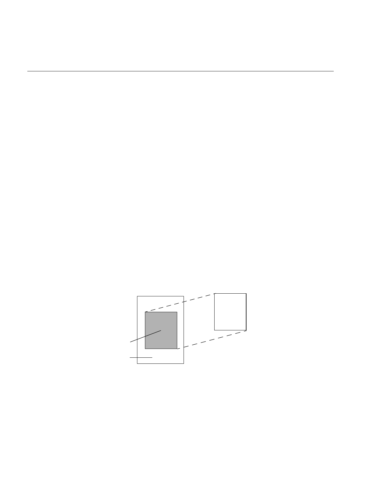
242
Chapter 6: Extending ImageVision Library
{
setValidType(iflFloat);
addValidOrder(iflSeparate);
setNumInputs(1);
addInput(src);
setCutoff(cutoff);
}
The constructor for this class takes an input source image and a cutoff level as arguments.
The freqFilt() function is implemented as shown below:
Deriving From ilRoi
ilRoi is an abstract base class, which means that an ilRoi cannot be created as an object. It
is intended to be used as a base class for deriving new types of region of interests (ROIs).
However, a pointer to an ilRoi can be declared for accessing any type of ROI.
ilRoi is derived from ilLink. As a consequence, ilRoi operators can be part of a chain of
objects with parent and child dependencies.
ilRoi abstracts the idea of a “region of interest” by defining various functions common to
all types of ROIs. A ROI is a 3-D object with its own x, y and z dimensions and its own
orientation. One can imagine a ROI being laid on top of an ilImage.
Figure 6-4 Visualizing a ROI
e
u2v2
+
cutoff2
------------------
–
ilROI
ilImage
valid region
invalid region

Deriving From ilRoi
243
All pixels of the ilImage falling inside the valid regions are ones that are operated on; the
rest are not affected. The same ilRoi object can be associated with different images (which
can be of different sizes), and it can be placed at different offsets within each image. An
ilRoi or any object derived from it can be associated with an ilImage through a class
called ilRoiImg.
You can use the getOrientation() and setOrientation() functions to manage the
orientation of the ilRoi object.
Different types of ROIs have different ways of describing valid (or foreground) and
invalid (or background) regions. A rectangular ROI (ilRectRoi) defines the valid region
as being inside or outside a rectangular area. An image-mapped ROI (ilImgRoi) uses an
input image as a ROI map; each pixel in the map is compared against a threshold value
to determine if it is valid or not; the comparison may be any of the Boolean operators
(equal, not equal, greater than, greater or equal, less than, less or equal). Alternatively,
you can use an ilImgRoi to divide an image into many different regions, each one
corresponding to a distinct pixel value in the image map.
Using an ROI: The ilRoiIter class
In order to apply an ilRoi object to an image, an iterator is required. The pure virtual
method createIter() maps the ROI object onto an image at a given offset, then constructs
and returns an iterator that can be used to step through the regions of the ilRoi.
Deriving New Classes From ilRoi
In order to define a new type of ROI, the developer must derive a new class of ilRoi as
well as a new class of ilRoiIter. You must define the virtual function, createIter(), to
construct and return an object of the new iterator class. The new ilRoi class usually needs
some other methods specific to its behavior; for example, the ilImgRoi class has methods
to set and get the image map, and set or get the comparison operator. These parameters
may also be passed to the ilImgRoi constructor.
Deriving New Classes From ilRoiIter
The ilRoiIter class provides functions that can iterate through an ROI. These functions
can be used within a specified rectangle (clip box) or an entire image. Once you create an
ROI, you can construct an iterator that binds the ROI to an image at a specified offset.

244
Chapter 6: Extending ImageVision Library
An ilRoiIter object provides the following functions to cycle through valid or invalid
data:
•next()
•nextMatch()
•ilRoiIterNext()
•ilRoiIterNextMatch()
The following functions return the starting location and lengths of the run lengths:
•getX()
•getY()
•getZ()
•getLen()
•ilRoiIterGetX()
•ilRoiIterGetY()
•ilRoiIterGetZ()
•ilRoiIterGetLen()
Once you create an ilRoiIter object, it may be used to step through the valid or invalid
regions defined by the ROI.
Each derived class of ilRoi requires a derived ilRoiIter class that iterates over the
run-lengths of the ROI. Deriving a new class requires only that you define the pure
virtual next() to advance to the next segment of the ROI.
An ROI segment is a length of pixels, consecutive in the X dimension, that lie entirely
inside or entirely outside the valid region. The iterator should advance in X first, then Y,
and finally Z (for 3D ROI’s).
The protected method update() performs some common post-processing that all
iterators need to do. A typical recipe for next() is shown below:
1. check if done
2. if so return FALSE
3. set last = pos

Deriving From ilRoi
245
4. remember where this segment started
5. set fore flag based on first pixel in segment;
6. (foreground/valid -> TRUE; background/invalid -> FALSE)
7. scan pixels while foreground state remains the same
8. call update()
9. return TRUE;


247
Chapter 7
7. Optimizing Your Application
This chapter is intended for programmers who are somewhat familiar with IL and who
want to optimize their applications. This chapter has two major sections:
•“Managing Memory Usage” on page 247 describes how to optimize the memory
usage of your application.
•“Using Hardware Acceleration” on page 253 describes what operations can be
accelerated on different graphics hardware.
Managing Memory Usage
You can optimize the performance of your application by making knowledgable
decisions about the use of memory resources. Three areas in which you can optimize use
of memory are:
•use of cache
•page size
•buffer size
The following sections describe these three areas in greater detail.
Optimizing Use of Cache
You can optimize the use of cache in your application in a number of ways. You can
change the size of the cache, control the automatic growth of cache that can occur if
multi-threading is turned on, set priority on an image in cache, and use tools to monitor
the use of cache.
Before reading further, you might want to refer to other parts of this manual that describe
caching. To learn about:
•caching and paging, read “The Cache” on page 32.

248
Chapter 7: Optimizing Your Application
•changing cache size using the functions ilSetMaxCacheSize() and
ilSetMaxCacheFraction(), read “Managing Cache” on page 35.
•using the ilCompactCache() and ilFlushCache() functions to compact global cache
memory, read “Managing Cache” on page 35
Cache Size
This section describes how to determine the cache size that is most appropriate to your
application. Every class descended from ilMemCacheImg (including all the image
operators) needs memory for a cache, which holds pages of image data. By default, IL
cache size is 30% of the total user memory on the system. In some applications this is too
large, in others it is too small.
The optimum cache size for any particular IL program depends on the size of the images
that the program manipulates and on the type of operations it performs on the data.
If your application:
•operates on small images, you can set the size of the cache to be the size of the
image, minimizing both memory and total processing needs.
•operates on large images, you will need a larger cache. A program with a large
image cache improves performance because it saves the processing overhead
required to move data in and out of memory. However, if the cache is too large and
uses up main memory, you could potentially be swapping pages in and out of
virtual memory on your system, which degrades performance.
•displays image data, its cache should be large enough to hold the displayed
window of data.
•just produces a reduced resolution version of an image in another image file, you
can get by with a smaller cache.
Typically, the cache will not be able to hold everything needed for an operation. For these
cases, set the cache at least large enough to hold both:
•one page of output data
•the number of pages of input data required to produce that page
For example, suppose that you are copying an image with pages that are 128 pixels
square (these are the default page dimensions for FIT images) to an image that sets the
page width to match the width of the image (this is true for SGI RGB images). Further,
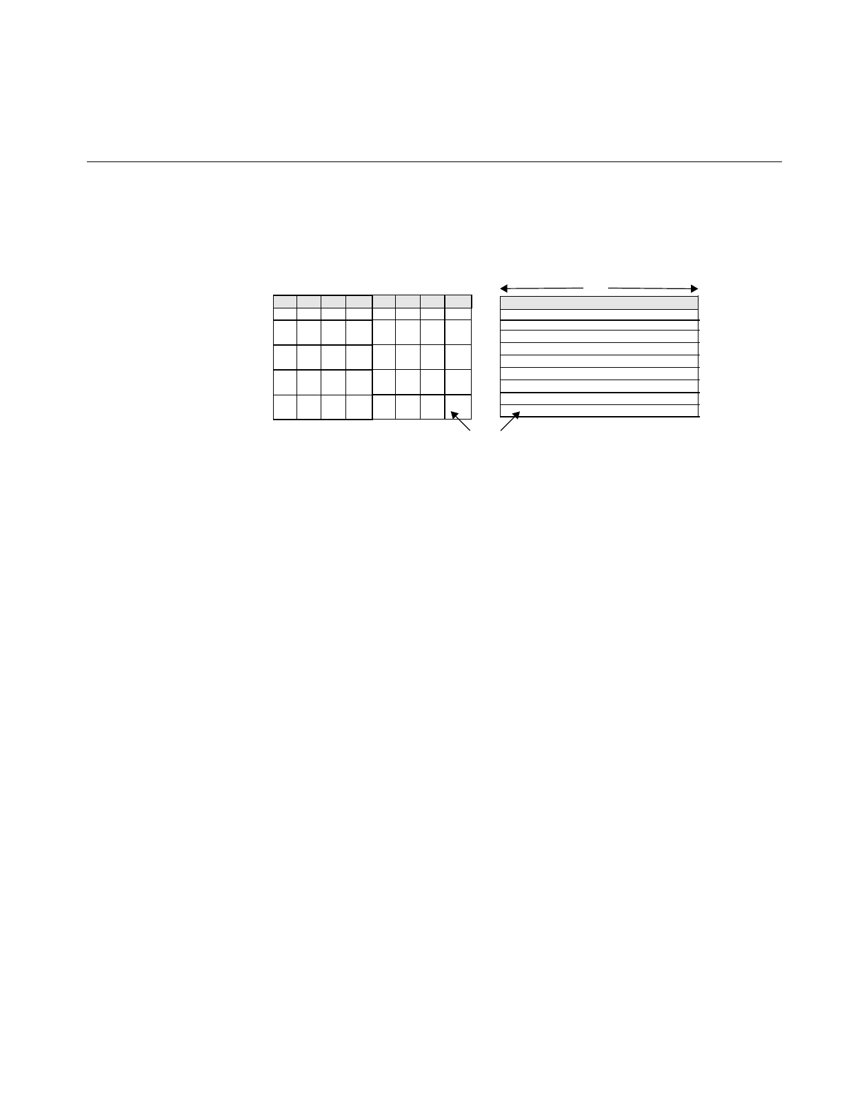
Managing Memory Usage
249
suppose that both images are 2K pixels wide and that the SGI image sets its page height
to 64 pixels. Figure 7-1 shows the two images and the pages contained in them. (This
figure is not drawn to scale.)
Figure 7-1 Varying Page Dimensions
To write a single 2 KB x 64 SGI page, you need data from all the FIT pages that span the
width of the image. Thus, in this example, set the cache size to (2 KB x 64 + 2 KB x 128) x
3 bytes (assuming that there are 3 channels and that the data type is iflChar). Add about
10% to this figure to allow for the size of page descriptors and other overhead. This
allows all needed pages to be held in the cache. If the cache is smaller than this, the data
can still be processed, but FIT pages are bumped out of the cache and then read back in
as successive SGI pages are written.
Effect of Multi-threading on Cache
The use of multi-threading can affect the size of cache in an application (see
“Multi-threading” on page 53). With multi-threading enabled, the cache can grow larger
than its preset limit if all the pages contained within it are locked down and another page
must be brought into the cache. This growth of cache prevents deadlock, but can cause
the application to use more memory than you wish. To prevent this behavior, do one of
the following:
•reduce the number of threads (so that there are never more threads than pages in
the cache)
•reduce the size of each page (so that there are enough pages in the cache for all the
threads)
•increase the size of the cache (so that there is one page for each thread)
128
128
64
FIT Image SGI Image
2K
Page

250
Chapter 7: Optimizing Your Application
For example, if there is room in the cache for only two of the operator’s pages but there
are four threads, the cache may be grown so that it contains four pages. If this is
unacceptable, either reduce the number of threads to two or reduce the size of a page by
half (so that the cache can contain twice as many, or four, pages). Multi-threaded
applications always need more memory to run efficiently; the best solution is to add
more memory to your system. If this is not possible, the next best solution is to reduce
the page size.
Cache Priority
As explained in “Priority” on page 36, the pages of an image that are brought into cache
as the result of an operation on the image are kept there until the cache becomes full.
When the cache is full, decisions must be made about which pages are kept in cache and
which are discarded and replaced by new pages.
IL attempts to optimize the use of cache. You can also affect the caching process by using
the setPriority() and lockPage() methods. It is helpful, when you are optimizing your use
of cache, to understand actions IL is also taking to accomplish this. IL considers these
factors as it manages the contents of cache:
•time since the last reference to a page. Pages most recently referenced are least likely
to be overwritten.
•number of references made to a page. Pages that are frequently referenced are least
likely to be overwritten.
•the destination of a page. IL automatically raises the priority of a page request for
data that is directly displayed. This has the effect of caching data at the end of a
displayed chain.
Sometimes it makes sense to cache data at points other than at the end of a chain. The
reference counting used in the page replacement algorithm can help to accomplish this
caching, but in cases where explicit knowledge of the application is required, you can use
the setPriority() method of ilImage to set the priority of the image containing the
specified page. For instance, you may want to raise the priority of the file input to a long
chain to avoid rereading the input if the chain is expected to be altered.
You may also want to raise the priority of the input to an operator that is having its
parameters interactively modified, although again the reference counting built into IL
will tend to automatically increase the priority for you.

Managing Memory Usage
251
Monitoring the Cache
You can monitor image data cache usage in two ways:
•by using the image tool ilMonitor. This provides an interactive means for you to
monitor the use of the cache. See “Image Tools” on page 276 for more information
about ilMonitor.
•by setting the environment variable IL_MONITOR_CACHE to a value of 1. This
causes IL to print a message for each page loaded into the cache or deleted from the
cache. The message identifies the page location in its associated image and the class
and address of that image.
It is often important to know about the operator images (such as color converters) that
are automatically inserted by IL. You can use ilDumpChain() to print out a simple
description of an IL chain.
An example using this environment variable is shown below:
% setenv IL_MONITOR_CACHE 1
% imgview /usr/demos/data/images/weather.fit
Page (0,0,0,0) loading in Color(0x10034ec8)
Page (0,0,0,0) loading in FIT(0x1001d010)
This example shows that a color converter operator image has been used to cache the
data from the FIT image in frame-buffer format. It also shows the background view with
ilConstantImg as input that is automatically created by ilDisplay. You can use this
technique to identify cache thrashing if you suspect it is occurring. You can eliminate
such problems by one of the techniques described in the preceding sections.
For more challenging situations, you may want to use the setPagingCallback() method
in ilCacheImg. Refer to the ilCacheImg reference page for more details.
Note: Do not attempt to use setPagingCallback() and ilMonitor at the same time since
ilMonitor uses the setPagingCallback() mechanism.
Page Size
Image data is always cached in pages. A file image’s page dimensions match those used
to store the image on disk. By default, an operator’s page size is defined by its input
images. Certain operators override this default size, which can affect the caching of
images. Some images also let you set the size of the pages in the cache and the data type

252
Chapter 7: Optimizing Your Application
and ordering of the cached data. The data type and ordering affect how data is cached,
so if you change these attributes, you might also want to change the size of the cache.
Operators (ilOpImg objects) can set minimum pages sizes to increase efficiency.
ilSpatialImg, for example, sets the minimum page size to a multiple of the kernel size.
Optimum Page Size
Operators are usually the only images that allow you to set the page size. The ideal page
size depends on the particular application, but in general you want an image’s page size
to be as close as possible to that of whichever image it is being copied to or read from. If
the application involves roaming on a large image, however, the page size should be
relatively square. The functions that change page size are defined by ilImage and are
explained in “Page Size” on page 38.
Large pages use up more memory, which is a problem when the cache grows beyond its
limit and starts allocating extra pages to get around deadlock. See the previous section
for suggested solutions. Making pages too small, however, forces too much processing
overhead. A page should not be smaller than 32 x 32 pixels, and in general the total
number of bytes in a page should be between 16KB and 64KB. This range typically works
out to be 128 x 128 to 256 x 256 when measured in pixels. Some operators, such as the
frequency domain ones, are more efficient when the page size is a power of 2.
Maximizing Efficiency When Copying Pages
The copyTile() method is an efficient way to copy a tile of data from one ilImage to
another:
ilStatus copyTile(int x, int y, int nx, int ny,
ilImage* other, int ox, int oy,
int* chanList=NULL);
By default, the tile is copied to the calling image from the image pointed to by other. The
x and y arguments specify the origin of the tile in the destination image, and nx and ny
specify the size of the tile. The tile that is to be copied is located at (ox,oy) in the other
image. (If the tile is at the same location in both the source and destination images, then
x=ox and y=oy.) If the source and destination images have different orientations, the data
is transformed automatically as necessary.

Using Hardware Acceleration
253
Buffer Space
You may sometimes need a temporary buffer to work on image data. Using copyTile()
instead of getTile() or setTile() to transfer data between images eliminates the need for
temporary buffers, saving you memory. copyTile() is explained in “Accessing Image
Data” on page 40.
In addition to temporary buffers you may allocate to hold data, IL allocates buffers to
operate on data internally. The amount of buffer space that IL can allocate at any one time
depends on the number of threads running concurrently. If three threads are performing
image processing operations on three tiles, in general, three buffers of the necessary sizes
must be used. However, extra buffer space is not used if the operator in question is
locking down pages, transferring data from input cache to output cache, and operating
on the data “in-place.” Certain operators derived from ilMonadicImg do this. If you
derive a new operator from ilMonadicImg or any of its descendants, you might want to
ensure that your derived class operates on its data in-place by setting its inPlace member
variable in the constructor.
Using Hardware Acceleration
IL can accelerate some image processing sequences on SGI computers that result in a
displayed image (as opposed to sequences that result in a file). This section describes
which IL operations can be accelerated, the constraints on these operations, and the
underlying graphics resource required for these operations.
Using Accelerated Operators
This section describes the operators that can be accelerated for display and the related
OpenGL functions that are required to accomplish the operators.
Accelerating ilAddImg, ilBlendImg, ilMaxImg, ilMinImg, ilMultiplyImg, and
ilSubtractImg Operators
These operators use the OpenGL blend facility to arithmetically combine two or more
input images. The primary (zero-th) input is rendered first to the frame buffer. Then the
subsequent inputs are rendered to the same location with the appropriate OpenGL blend
function enabled to accomplish the operation.

254
Chapter 7: Optimizing Your Application
ilMultiplyImg can only be accelerated if both input min values are zero.
ilSubtractImg is accomplished by negating the secondary input. Only
constant-alpha-type blending can be accelerated.
In some cases, the operation cannot be accelerated if the input data ranges differ.
Accelerating ilAndImg, ilInverImg, and ilXorImg Operators
These operators use the OpenGL logic OP facility to logically combine two or more
images. They use multi-stage rendering operations similar to that of ilBlendImg.
ilInvertImg, however, is done in a single rendering operation.
Accelerating ilConvImg and ilSepConvImg Operators
Convolution operators use the OpenGL 2D convolution extension. To facilitate
acceleration, the kernel data must
•be of type float
•be of one of the following sizes: 3x3, 5x5, 7x7
•have the origin in the center of the kernel
Using the ilFalseColorImg Operator
IL uses the OpenGL color matrix. The matrix size must be less than or equal to 4x4. The
bias must be zero. Some matrices with negative weights may not be accelerated because
they cannot be scaled correctly.
Using ilLutImg, ilHistLutImg, and ilThreshImg Operators
IL uses OpenGL color tables. OpenGL provides four color tables (see Table 3-3). The color
table that is used for a particular operator depends on the LUT input (see Composition).
LUTs can be up to 4K long.
Using ilScaleImg, ilHistScaleImg, and ilNegImg Operators
IL uses OpenGL pixel scale, bias, and clamping facilities. These facilities are also used to
normalize input data ranges to the intrinsic zero to one ranges and to compensate for
convolution kernel and colormetric affects on the operator value ranges.

Using Hardware Acceleration
255
Accelerating ilWarpImg Operators
IL uses OpenGL texture rendering. There are two cases, depending on the type of warp,
associated with operators:
•affine or perspective warp
•any other type of warp
The first case sets the modelview matrix to perform the desired warp. The second case
represents the warp with a regular triangular mesh. For certain simple zooms, for
example, affine and perspective warp, the OpenGL pixel zoom facility is used instead of
texture.
The texture required for other warp cases is associated with the input of the warp
operator. Thus, multiple warp operators that share input also share the same texture. See
for more information about IL’s use of texture.
Accelerating the ilImgStat Operator
IL uses OpenGL’s histogram and minmax facility. The number of histogram bins must be
less than or equal to 4096. The input data order must be interleaved. An ImgStat with a
rectangular ROI can be accelerated, but one with any other kind of ROI cannot.
Note: ilHistLutImg and ilHistScaleImg use ilImgStat. Therefore, they accelerate
statistics-gathering and the rendering parts of the operations.
Understanding the OpenGL Imaging Pipeline
The OpenGL Imaging Extension (OIE) specifies a sequence of image processing
operations that can be enabled during a pixel transfer operation. A pixel-transfer
operation can be one of the following:
•an image is drawn from the host memory to the frame buffer
•an image is copied from one frame buffer to another
•an image is loaded from the host to texture
•an image is copied from the frame buffer to texture
In each case, a rectangle of pixels is transferred from one buffer to another. During the
transfer, any of the image processing operations shown in Figure 7-2 can be active.
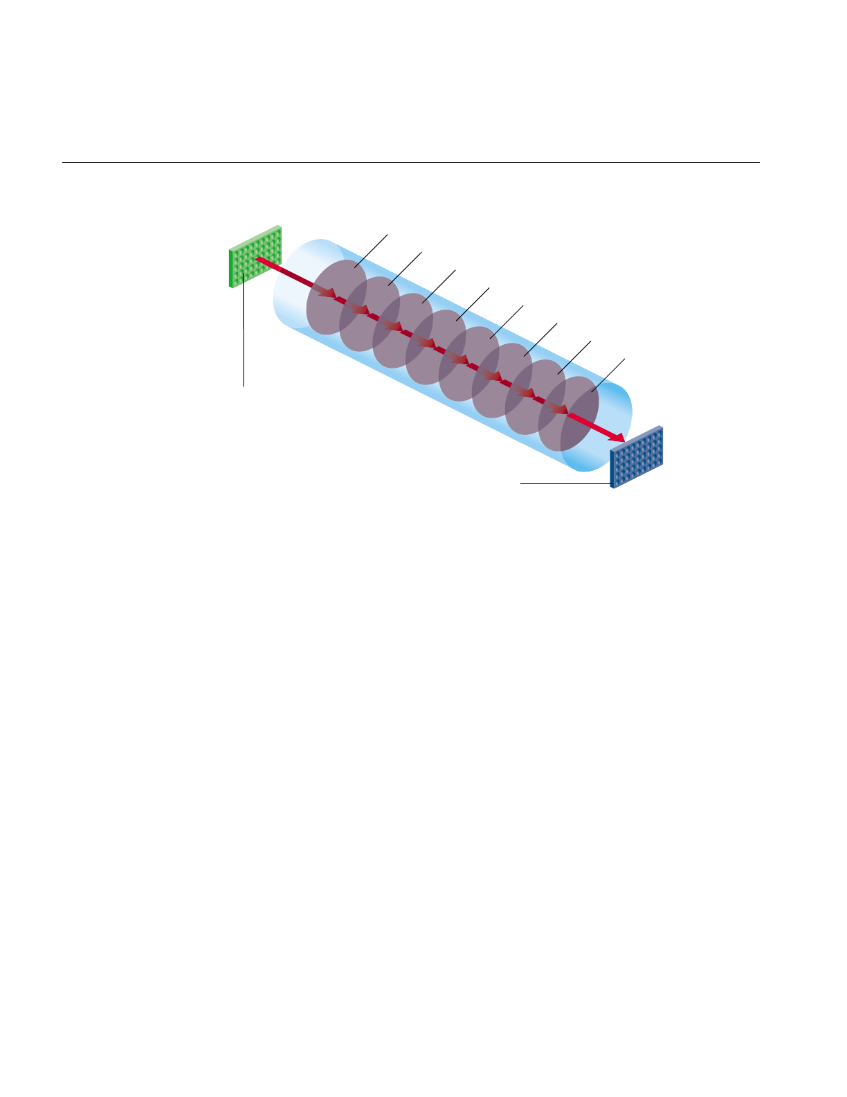
256
Chapter 7: Optimizing Your Application
Figure 7-2 OpenGL Image Processing Pipeline
In Figure 7-2, the input can be the host memory or a GL buffer, the output can be a GL
buffer, texture, or host memory, and S/B/C stands for scale/bias/clamp operators. To
use hardware acceleration, the operators must follow the order in Figure 7-2. Not all of
the operators need to be enabled. What is not allowed, for example, is Lut1 to precede
S/B/C1. If you need to use operators out of order, you need to use pixel buffers, as
described in “Pixel Buffers and Multi-Pass Acceleration” on page 258.
Most of the accelerated IL operators use one or more elements in the Image Processing
pipeline.
Composing Operators
Since the OGLIP supports a sequence of operations in a single operation, it is possible to
compose several IL operators for acceleration, provided they occur in the right order, for
example, IL chain shown in Figure 7-3 can be displayed by copying the file image cache
directly to the frame buffer while enabling the subsection of the OGLIP pipeline shown
in Figure 7-4.
Lut
1
Input buffer
Output buffer
S/B/C
1
Conv
S/B/C
2
Lut
2
Color matrix
1
S/B/C
3
Lut
3
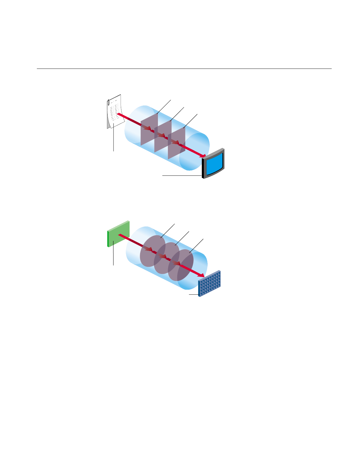
Using Hardware Acceleration
257
Figure 7-3 IL Chain Mapped to the OGLIP Pipeline
Figure 7-4 shows that all three operators are accelerated. ilSqRootImg, ilSharpenImg, and
ilSaturateImg correspond to Lut1, Conv, and Color Matrix, respectively.
Figure 7-4 Mapping onto the OGLIP in a Single Transfer
However, if the chain is reordered, as shown in Figure 7-5, so that the sharpen occurs
after the FalseColor, the sequence cannot be fully accelerated because it does not match
the sequence of operators in the OGLIP pipeline. When a sequence cannot be wholly
mapped to the OGLIP, IL selects the longest subsequence to run as a single operator.
ilSharpenImg
ilFileImg
ilView
ilSqRootImg
ilSaturateImg
Lut
1
Host
memory
Frame buffer
Conv
Color matrix
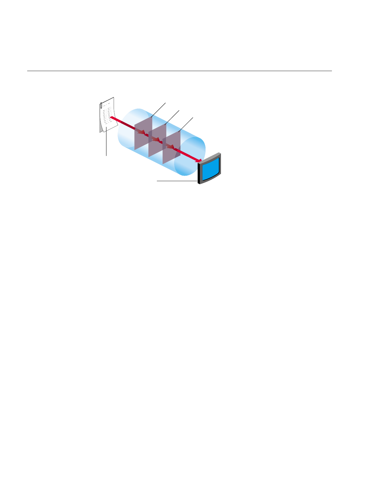
258
Chapter 7: Optimizing Your Application
Figure 7-5 Running a Subsection of an IL Chain
Given the IL chain shown in Figure 7-5, only the sharpen operator would be accelerated
with a single-pixel transfer. The other two operators would be evaluated in the normal,
unaccelerated manner.
The next section describes how chains as shown in Figure 7-5 can be fully accelerated
through the use of pixel buffers.
Pixel Buffers and Multi-Pass Acceleration
OpenGL provides non-volatile, off-screen framebuffer memory, called pixel buffers, for
storing intermediate results. This feature enables IL to fully accelerate chains that do not
completely map onto the OGLIP as a single transfer operation. For example, the IL chain,
shown in Figure 7-6, is accelerated with the two-pass sequence of transfer operations.
ilSharpenImg
ilFileImg
ilView
ilSqRootImg
ilSaturateImg
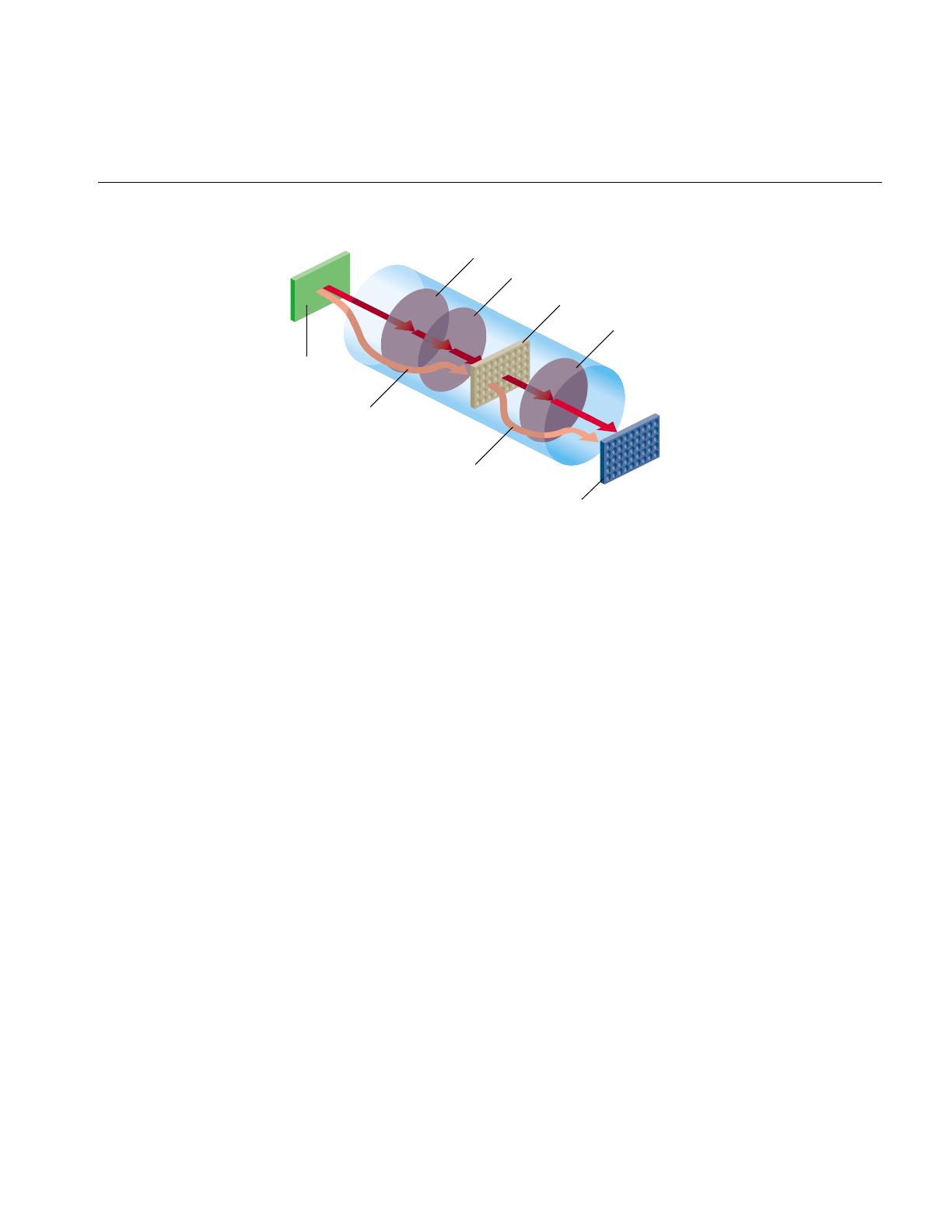
Using Hardware Acceleration
259
Figure 7-6 Two-Pass Transfer Operations
Pixel buffers are, in general, eight to twelve bits per component. The exact depth of the
pixel buffers can be determined by examining the attributes of the glx visual associated
with the pixel buffer. The command
% glxinfo -fbcinfo
prints a summary of the available visuals. The limited depth of the pixel buffers limits
the precision of the stored image data.
Pixel buffers are allocated by IL in units of the display size. The total number of allocated
pixel buffers can be limited either programmatically through calls to
ilSetNumPBuffers() and ilGetNumPBuffers(), or through the environment variable
IL_NUM_PBUFFERS.
Texture
IL employs the OpenGL texture facility to accelerate warp operators. From the
standpoint of hardware accelerators, a texture is an intermediate storage buffer similar
to a pixel buffer. However, the size of the texture is usually smaller and the component
depth is shallower. The component depth is dependent on the resampling mode for the
warp (for example, ilNearNb, ilBiLinear, and ilBiCubic) and the color model.
Lut
1
Host
memory
Frame buffer
Convolve
Pixel buffer
glDrawPixels()
Color matrix
glCopyPixels()
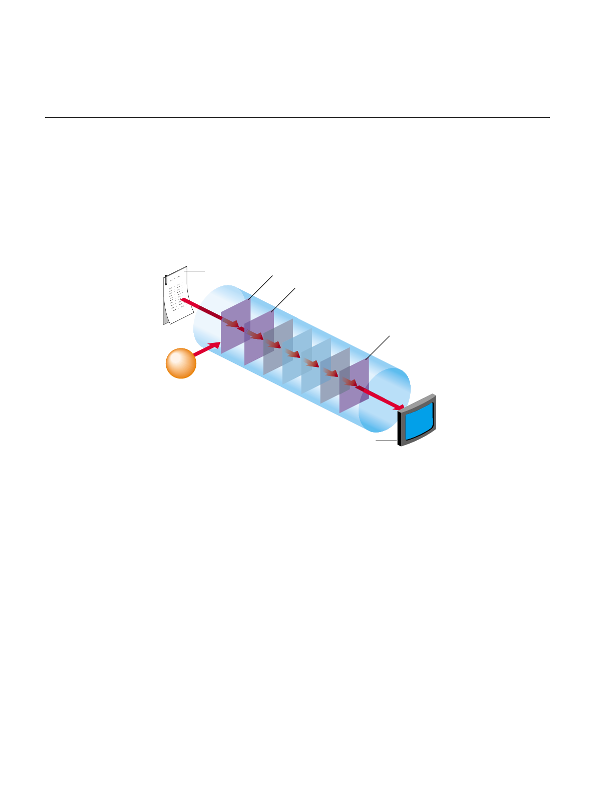
260
Chapter 7: Optimizing Your Application
A texture is associated with the input of a warp. If several warp operators share the same
input, they also share the same texture. The texture cache is unaffected if the warp is
interactively altered to enable fast, interactive displays of changing warps.
IL provides limited support for displaying a combination of warps in a single rendering
pass. Specifically, you can string together any number of perspective (ilPerspWarp) and
affine (ilAffineWarp) warps into a single step. This combination of warps is called a
transform matrix. Figure 7-7 shows an IL chain of operators.
Figure 7-7 Accelerating an IL Chain Using Texture
Figure 7-8 shows the underlying data path of the IL chain in Figure 7-7.
ilRotZoom
ilAffineWarp
ilPerspWarp
ilRotZoom
ilAffineWarp
ilPerspWarp
ilFileImg
ilView
ilWarpImg
1
n
User
warp
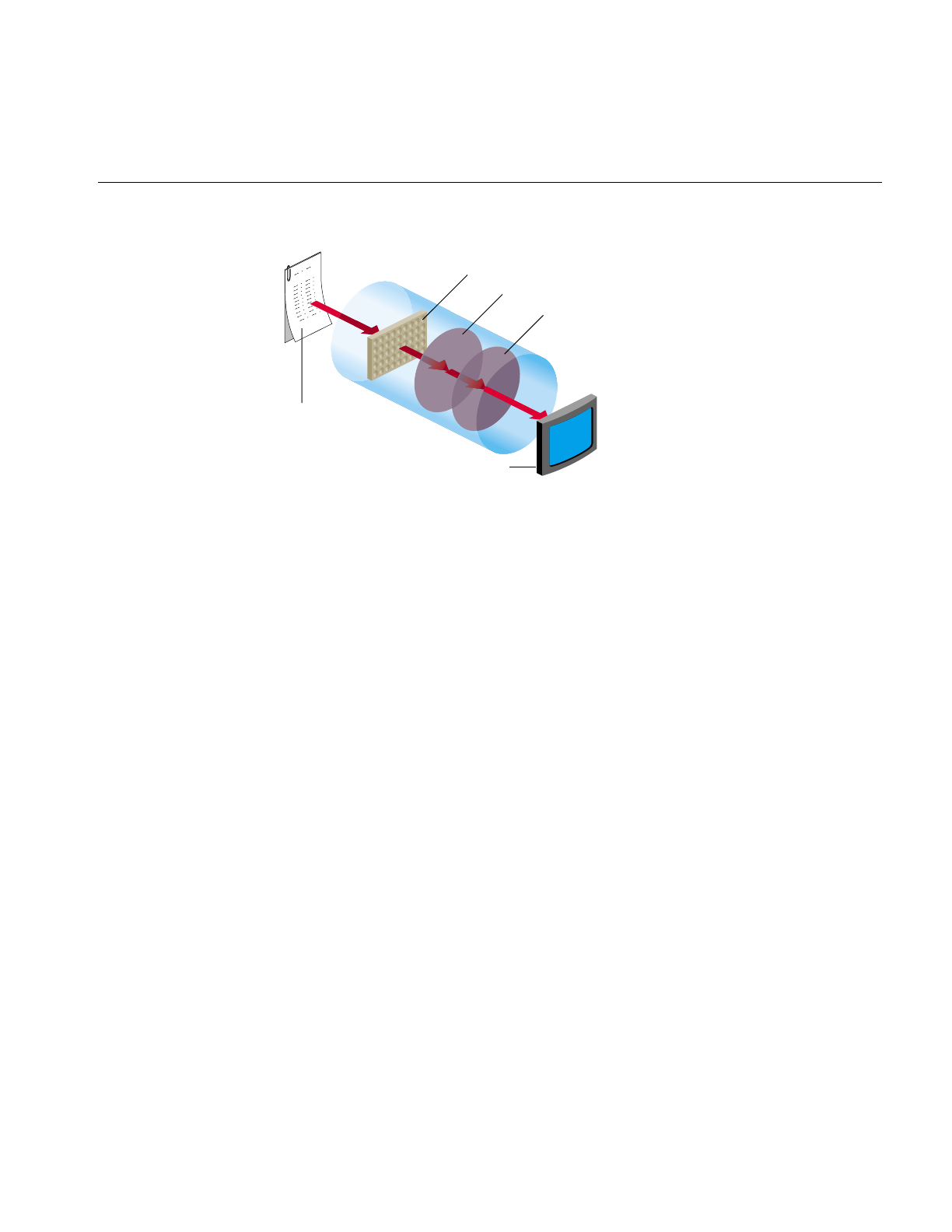
Using Hardware Acceleration
261
Figure 7-8 Data Path of the IL Chain in Figure 7-7
Figure 7-8 shows that IL associates a texture with the ilFileImg object and derives a
triangular mesh from the user-defined warp. All of the perspective warps, affines, and
rotzooms are combined into the transform matrix. When any of these warp values
change the images change accordingly, however, changing the transform matrix does not
change the cached values for the texture and the triangular mesh. By preserving these
cached values, the use of the transform matrix accelerates image processing.
When the input image is larger than the texture, the data must be paged into texture
according to what is currently being viewed. When the texture requirement for a
particular rendering operation greatly exceeds the texture capacity, performance
degrades. In this situation, rendering is limited by the rate that texture can be loaded into
the cache rather than by the rate that it can be rendered.
The triangular mesh associated with a general warp is also paged into memory so that
only the displayed portion of the warp is evaluated. The results are cached and reused in
subsequent rendering operations.
Seeing Evidence of Pixel Buffer Use
The difference between the pipelines in Figure 7-3 and Figure 7-5 is that Figure 7-5 uses
a pixel buffer as an intermediary to create the final image. By turning on the monitor, you
can view the use of the pixel buffer in each pipeline by using the imgtcl program, which
is included in the software distribution. To view the results of Figure 7-3 at each stage of
the pipeline, use the following commands:
ilFileImg
ilView
Triangle mesh
Texture
Transform matrix

262
Chapter 7: Optimizing Your Application
% setenv IL_MONITOR 2
% imgtcl
imgtcl> ilfileimgopen monkey /images/monkey.rgb
monkey
imgtcl> view monkey
imgtcl> ilSqRootImg sqroot monkey
sqroot
imgtcl> view sqroot
imgtcl> ilSharpenImg sharp sqroot
sharp
imgtcl> view sharp
imgtcl> ilSaturateImg sat sharp
sat
imgtcl> view sat
To view the results of the pipeline in Figure 7-5, reverse the ilSharpenImg and
ilSaturateImg commands, as follows:
% setenv IL_MONITOR 2
% imgtcl
imgtcl> ilfileimgopen monkey /images/monkey.rgb
monkey
imgtcl> view monkey
imgtcl> ilSqRootImg sqroot monkey
sqroot
imgtcl> view sqroot
imgtcl> ilSaturateImg sat sqroot
sat
imgtcl> view sat
imgtcl> ilSharpenImg sharp sat
sharp
imgtcl> view sharp
Because the first two operators are the same in the pipelines shown in Figure 7-3 and
Figure 7-5 their images and monitor displays are identical. Figure 7-9 and Figure 7-10,
however, show the differences in the images and monitor displays caused by reversing
the ilSaturateImg and ilSharpenImg operators.
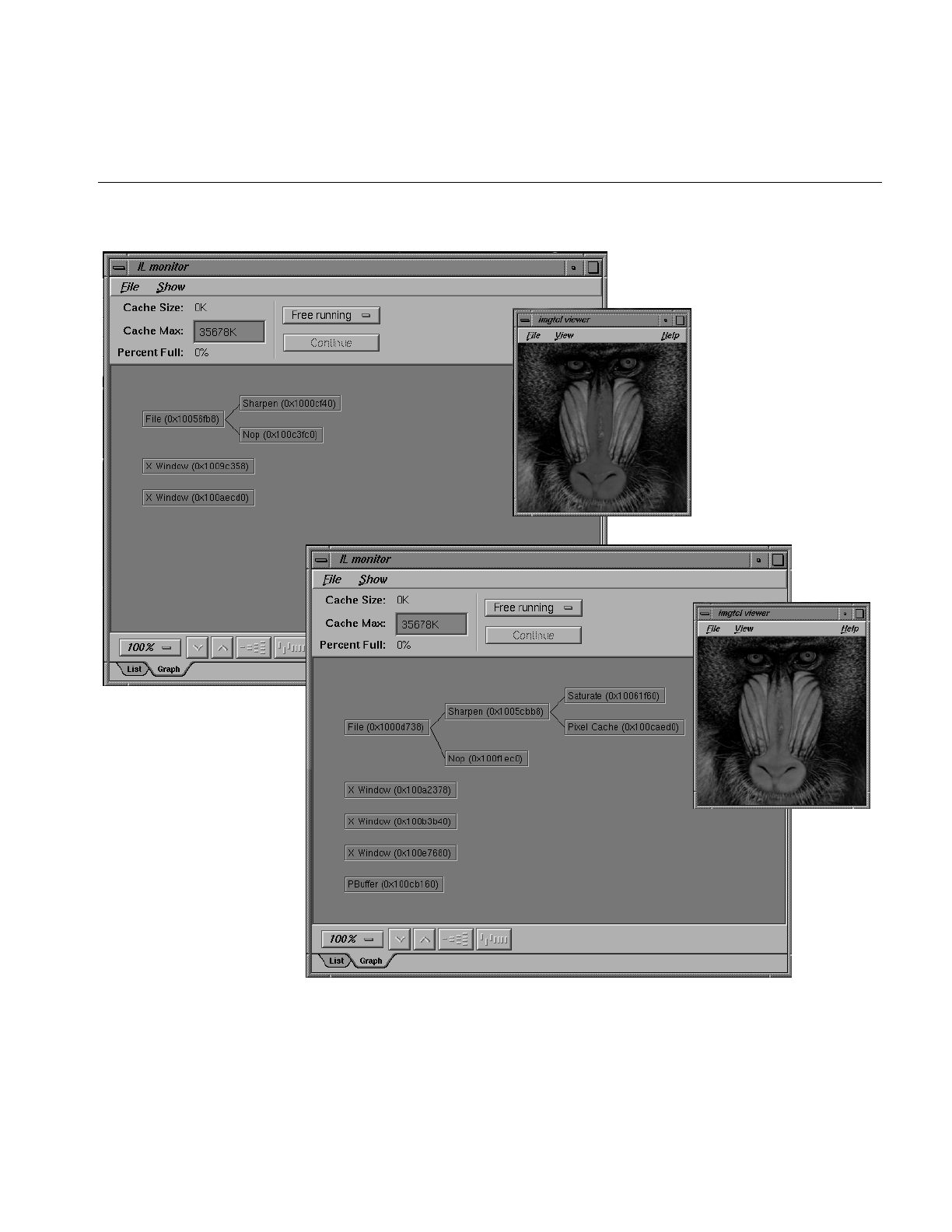
Using Hardware Acceleration
263
Figure 7-9 Hardware Acceleration Without Using Pixel Buffers

264
Chapter 7: Optimizing Your Application
Qualitatively, you can see that changing the order of the operators introduces added
complexity in the monitor displays shown in Figure 7-10. More specifically, you can see
that the ilSharpenImg operator in Figure 7-10 introduces the use of a pixel buffer.
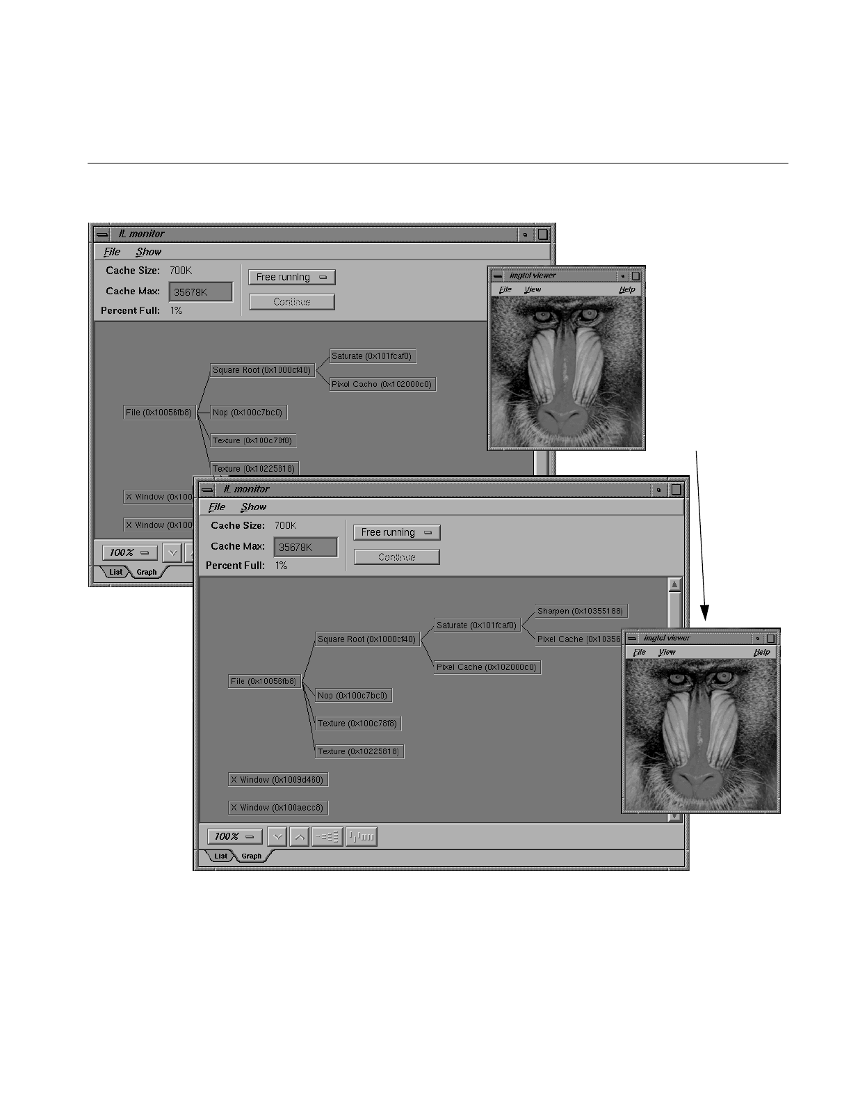
Using Hardware Acceleration
265
Figure 7-10 Hardware Acceleration Using Pixel Buffers
pixel buffer used

266
Chapter 7: Optimizing Your Application
Texture Allocation
The total number of bytes of texture is configurable. The installed amount is encoded in
the OpenGL renderer string. For more information, see the man page for glGetString.
Texture is divided into two logical banks. Bilinear and nearest neighbor textures are
allocated within a single bank. Therefore, the maximum texture size for bilinear and
nearest neighbor texture is half the installed amount. Bicubic texture allocation is split
across the two banks. Therefore the maximum size of a bicubic texture is the same as the
installed amount.
Whenever a warp image is accelerated with texture, an auxiliary texture is managed that
shadows the input to the warp image. The size of this texture must be a power of two. If
the image is larger than the maximum allocatable texture size, then the maximum size
texture is used and maintained as a wrap-around image cache.
Hardware-Specific Acceleration Restrictions
This section describes the limitations and operating parameters for hardware
acceleration on different platforms.
General Restrictions
The following restrictions apply to all platforms:
• The default pbuffer depth is based on the available X Visuals on the system. The
depth is determined by selecting the greatest-order visual class, usually TrueColor,
that has at least 8 bits per component, and includes alpha planes. It is not possible to
copy from a pbuffer to a window (or another pbuffer) with a different visual class.
• Convolution kernel sizes must be 3x3, 5x5, 7x7, separable or general, and of type
float. The edge mode must be ilPadSrc, ilPadDst, or ilNoPad.
•The color matrix (for ilFalseColorImg and ilSaturateImg acceleration) has. at most, 4
x 4 entries. The bias vector for ilFalseColorImg must be all zeros and the matrix
should have equal gain for each output channel, that is, the sum of the positive
elements and the sum of the negative elements should be the same for each matrix
row.
• The look-up table size must be limited to 4096 entries.

Hardware-Specific Acceleration Restrictions
267
• The histogram size must be limited to 4096 entries.
• Multiply is accelerated only if the minimum scale value of the input images is zero.
• Add is not accelerated for images with greater than two inputs.
•Statistics are accelerated only for interleaved data.
•The amount of texture available depends on the amount of texture memory
available in the system and the texture data format. An application should use
ilHwConnection::getTexCapacity() to determine the amount of texture available on
any given platform.
For any platform, an application should get at least one pbuffer for any framebuffer
configuration unless another application has taken all of the pbuffers.
InfiniteReality
Currently, the maximum amount of texture memory is 64 MB. The number of pbuffers
depends on the number of installed Raster Manager (RM) boards and the depth (in bits)
of the pbuffer. At the default depth, 12 bits, a 1 RM system can allocate 2 pbuffers.
The maximum texture lookup table size is 4096 entries if the texture and lookup table
format is single component, 2048 if neither format is more than 2, 1024 otherwise. These
numbers assume another application has not already taken the pbuffers.
Reality Engine
Restrictions for the Reality Engine are the same as for the InfiniteReality, except for the
following conditions:
•The maximum amount of texture memory is 16 MB.
•The OpenGL imaging pipe is restricted. It contains none of the extended lookup
tables, except for the texture lookup table.
•Color matrix cannot be concatenated onto a convolution.
•No pixel transformations in the imaging pipe can be active when loading texture.
The same is true for statistics operations.
•The maximum texture lookup table size is 256.
•Textures (and display lists) cannot be shared across GLX contexts.

268
Chapter 7: Optimizing Your Application
•InfiniteReality does not support bicubic texture resampling.
•Cannot accelerate conversions from color palette data to RGB.
•Cannot load texture from pbuffer safely. (The data cannot be swapped and may be
obliterated due to a contending process.) It is disabled by default. It can be enabled
by setting the hint, IL_TEXTURE_FROM_PBUFFER_OK_HINT.
Impact/High Impact
Restrictions for the Impact are the same as for the InfiniteReality, except for the following
conditions:
•Max Impact has 1 MB of texture memory, High Impact has 1 MB of texture memory,
and Certain Impact has no texture memory.
•The maximum texture lookup table size is 256.
•Impact does not support bicubic texture resampling.
•Impact cannot convolve if the input is float type.
•Impact cannot convolve into texture.
•Some framebuffer configurations of High Impact do not support pbuffers.
Indy/Indigo2
Only blend, logic op, and arbitrary zoom are supported on an Indy. On Indigo Entry, XS,
XZ, Elan, or Extreme, only blend, logic op, and integer zoom are supported.
Hardware Hints
The ilHwHint class provides a mechanism for setting hardware-specific attribute values.
You can use this mechanism with the hints provided in the ImageVision library or you
can create hints of your own.
You can set hints globally or on operators. Hints set on operators take precedence over
globally-set hints.

Hardware Hints
269
An example of a hint is IL_TEXTURE_FORCE_HINT, which is defined in IL. This hint is
used on warp objects to force the warp operator to use texture even when a pixel zoom
could be used.
Using IL-Recognized Hints
Because ilHwHint::setHwIntHint() is overloaded, you can set a hint using either a hint
name or ID. Using a hint name causes a hit in performance because it requires a lookup
of the hint name. It is more convenient, however, to set a hint using its name. If you set a
hint repeatedly, use the hint ID to set it. If you set a hint only once, use the hint name to
set it.
Using the Hint ID
Because hint IDs are set at runtime, your application must first lookup a hint ID, save the
ID so that it does not have to be looked up again, and set the hint using the hint ID.
Example 7-1 shows this procedure.
Example 7-1 Using the Hint Name to Set a Hint
int texSizeIntHintID;
// Find and save the hint ID using its name.
texSizeIntHintID = ilHwFindHintID(“IL_TEXTURE_SIZE_HINT”);
// Create a RotZoom object to rotate the image by 30 degrees
ilRotZoomIMg rz(input, 30, 1, 1, BiLinear);
// Set the hint on the RotZoom object to limit the texture size
// to 1 million texels.
input->ilImage::setHwIntHint(texSizeHintID, 1024*1024);
Using the Hint Name
Instead of going through the trouble of finding the runtime hint ID and then setting the
hint based on it, you can just set the hint using the hint name, as follows:
input->setHwIntHint(IL_TEXTURE_SIZE_HINT, 1024*1024);
The trade-off for this easier construction is slower performance.

270
Chapter 7: Optimizing Your Application
IL-Recognized Hints
Table 7-1 describes the ilHwHint values currently recognized by IL.
Table 7-1 ilHwHint Definitions
Name Description
IL_TEXTURE_SIZE_HINT Uses int-valued hint to control the size in texels of
a warp operator input texture.
IL_TEXTURE_COMPONENT_SIZE_HINT Uses int-valued component size hint to control the
warp operator input texture.
IL_TEXTURE_MESH_STEP_HINT Uses int-valued hint to control the warp mesh step
size.
IL_TEXTURE_MESH_PAGE_X_HINT
IL_TEXTURE_MESH_PAGE_Y_HINT
Controls warp mesh page size (should be a power
of two).
IL_PIXEL_BUFFER_WIDTH_HINT
IL_PIXEL_BUFFER_HEIGHT_HINT
Uses int-valued hints to control pixel buffer
dimensions.
IL_TEXTURE_FROM_PBUFFER_OK_HINT Uses int-valued hint to enable sourcing texture
from pixel buffer on RE (off by default because
correct texture swapping is not guaranteed).
IL_TEXTURE_LIMIT_HINT Uses int-valued limit in bytes to control global
texture allocation for an application.
IL_TEXTURE_FORCE_HINT Makes a warp object use texture, even if it could
use pixel zoom.
IL_FORCE_PASS_HINT Disables composing with input pass; effectively
creates a multipass operation with pixel buffer
cache between them.
IL_ROAM_VIEW_HINT Chains a texture onto an image when displayed in
an ilView; allows for fast roaming over an image.
IL_HW_HINT_ALERT_PROP_NAME Marks an ilLink-derived object as altered when a
parent’s hints are changed or when the global
hints are changed.

Hardware Hints
271
Creating Your Own Hints
If you are implementing your own hardware acceleration, you may need to create your
own hints to control it. The ilHwHint class pairs a name with a value. You use these
values to optimize the performance of your application. The base class provides the
means to set and get the name in the following methods:
ilHwHint(const char* hintName);
const char* getHintName();
ilHwHint(int hintID);
ilHwFindHintID(const char* hintName)
The base class does not. however, provide methods to set or maintain values associated
with hint objects; that job is left for ilHwHint-derived classes. For example, you could
provide access to some integer value associated with a derived hint-class object,
ilHwIntHint, as follows:
class ilHwIntHint : public ilHwHint {
public:
ilHwIntHint(int hintVal) : ilHwHint(“ilHwIntHint”)
{ val = hintVal; }
private:
int val;
};
Note: You can use the base class directly only if the hint object does not need to define
an explicit value. In some cases, the presence of a hint on a hint list is sufficient.
When you create a hint object, it is assigned an ID. The first object has an ID of zero and
the following objects have ID numbers of 1, 2, 3, and so on. You can retrieve the ID of a
hint using the following ilHwHint method:
int getHintID()
You can use hint IDs to accelerate hint lookups in a list of hints. To look up a name, use
the name of the hint or its ID, if the derived class caches it. Hint lists are described further
in “Hint Lists” on page 272.

272
Chapter 7: Optimizing Your Application
Hint Lists
ilHwHintList manages a hint list, which is an array of hints. Using hint lists can
dramatically improve performance by reducing lookup delays.
To add a hint to a hint list, use one of the following methods:
ilStatus setHint(ilHwHint* hint, int adopt = FALSE);
ilStatus setIntHint(int hintID, int val);
ilStatus setIntHint(const char* hintName, int val);
To return the hint specified by a name or ID, use one of the following methods:
const ilHwHint* getHint(int hintID) const;
const ilHwHint* getHint(const char* hintName) const
int getIntHint(int hintID, int& val) const;
int getIntHint(const char* hintName, int& val) const;
To remove a hint, specified by a name or ID, from a hint list, use one of the following
methods:
ilStatus removeHint(int hintID);
ilStatus removeHint(const char* hintName)
ilStatus removeHint(ilHwHint* hint)

273
Chapter 8
8. The Programming Environment
This chapter describes the programming environment available on Silicon Graphics
workstations. Special tools are also described that may help you in writing, compiling,
and debugging your IL program.
This chapter contains the following major sections:
•“Compiling and Linking an IL Program” on page 273 describes what you need to
do to compile an IL program written in C++, C, or Fortran.
•“Reading the Reference Pages” on page 275 explains how to read the class reference
pages. These reference pages do not follow the standard UNIX® reference page
format.
•“Image Tools” on page 277 describes some image tools that were developed using
the IL.
•“Online Source Code” on page 277 describes the IL-related code that is available
online.
•“Environment Variables” on page 278 describes how to configure the global IL
environment.
Compiling and Linking an IL Program
The following sections show you how to compile and link IL programs written in C++
and C.
Programs Written in C++
To compile an IL program, in this example, sample.c++, use the following command line:
# cc -g sample.c++ -o sample -lil

274
Chapter 8: The Programming Environment
By default, the *.so libraries are used to link your programs, however, you must link to
the IL library itself.
In general, you should not link to the static, *.a, libraries unless you want to keep your
application in one complete binary. If you do choose to use the static libraries, use the
following command to compile your program:
# cc -g sample.c++ -o sample /usr/lib/libil.a /usr/lib/libifl.a -lil
-lm -lGL -IX11
If you link to the static libraries, include the IL library, the GL shared library, the X
Window library, the math library, and the C++ library.
A Sample Makefile
Example 8-1 shows a sample Makefile for compiling IL programs.
Example 8-1 Makefile for a C++ Program
# Makefile for IL test programs
SHELL = /bin/sh
# If you want to debug,turn on the “-g” option.
FLAGS = -g
MAINS= sample.c++
OBJS = ${FILES:.c++=.o}
PROGS = ${MAINS:.c++=}
LIBS = -lil
.c++:
CC $(FLAGS) $< -o $@ $(LIBS)
.c++.o:
CC $(FLAGS) -c $<
clean:
rm -rf $(OBJS) $(PROGS)
rm -rf core

Reading the Reference Pages
275
Programs Written in C
Link your C program to the libcil.so library, the C version of the IL. For example, to
compile a C program called ctest.c, use this line:
# cc -g ctest.c -o carprot -lcil
IL is compatible with ANSI C. To use the older, pre-ANSI dialect, add –cckr to the
command line. Ignore any warnings generated during compilation.
Refer to the C reference page for more information about the C compilers.
A Sample Makefile
Example 8-2 shows a sample Makefile for compiling IL programs written in C.
Example 8-2 Makefile for a C Program
# A very simple Makefile for IL test programs
SHELL = /bin/sh
FLAGS = -g
CMAINS = csample.c
COBJS = ${CMAINS:.c=.o}
CPROGS = ${CMAINS:.c=}
CLIBS = -lcil
.c:
cc $(FLAGS) $< -o $@ $(CLIBS)
clean:
rm -rf $(COBJS)
rm -rf core
clobber: clean
rm $(CPROGS)
Reading the Reference Pages
IL reference pages look atypical because they are class reference pages. They are available
online by typing the following on the command line:
# man -d ClassName

276
Chapter 8: The Programming Environment
ClassName is the name of the IL or IFL class that you want to read about.
A printed version of the reference pages is available as an option; see the Introduction for
ordering information.
The C++ and C versions of the class reference pages share a similar format. The following
list describes the main sections of each reference page:
Name The class name and a one-line description of the class.
Inherits From A colon-separated list of superclasses, beginning with the base class.
Header File The class’s header file.
Class Description
Describes how the class fits into the IL and how to use it. This section
briefly mentions the most important functions associated with the class.
The C++ version also contains information about deriving from the
class, if appropriate.
Class Member Function Summary
Lists the prototypes of the functions associated with the class. They are
grouped functionally with headings that indicate the general task they
perform. Functions that are protected are identified as such. This section
should be a synopsis of the class.
Function Descriptions
Describes what each function does and what its arguments mean.
Sometimes code examples are included. This section is arranged
alphabetically so that you can easily find the description of a particular
function of interest.
Inherited Member Functions
Contains an alphabetical list of the functions inherited from
superclasses.
See Also Lists other reference pages of interest.
Notes (optional)
Contains special information about the class.

Image Tools
277
Image Tools
IL provides several useful utilities for displaying, copying, and manipulating images.
Since these image tools are based on IL, they support TIFF, SGI, PCD (Photo CD), PCDO,
TCL, PNG, GIF, and FIT file formats. These tools are installed in /usr/sbin and most of
them are documented in the IRIS Utilities User’s Guide. (They also have reference pages.)
imgcopy Image Copy copies a specified region of an input image file to an output
image file. It can also be used to convert between IL-supported file
formats. See the imgcopy reference page.
imginfo Image Info reports image information such as size, data type, color
model, and file format for any IL-supported file format. See the imginfo
reference page.
imgview Image View allows you to display and manipulate any combination of
IL-supported image files. Images can be roamed, dragged, cropped, or
wiped separately or simultaneously. See the imgview reference page.
imgformats Image Formats lists all the IL-compatible formats currently installed.
Online Source Code
To provide you with source code examples, IL installs several directories in
/usr/share/scr/il. They are as follows:
•guide contains the whole-program examples presented in this guide. They are
provided so that you can compile and run them as you read the relevant discussion
in the guide.
•apps contains sample IL applications, such as imgcopy and imgview. These
applications serve as examples of how to program with the IL and serve as possible
templates for developing new applications.
•src contains IL source code that may use to derive your own classes. The directory
includes the source for several operators, including the ilViewer class. The
corresponding header files are in /usr/include/il or /usr/include/ifl.
•tutorial contains a series of programs that build on one another. The first in the series
(ex0.c++) simply opens and displays an IL image file. The other programs use
various operators and display techniques.

278
Chapter 8: The Programming Environment
You can examine the README files in the various directories for more information on
each of the code examples. Also, each of the directories containing complete programs
has an appropriate Makefile. To compile any of the programs, type:
# make program_name
where program_name is the name of the file minus its .c++ suffix.
Environment Variables
You use environment variables to configure the global IL environment. Environment
variables configure such things as the file format, multi-processing, graphics hardware
acceleration, caching capabilities, and monitoring functions.
Table 8-1 provides a brief description of the environment variables with their default
values.
Table 8-1 Environment Variable Definitions
Environment Variable Definition and Default Value
IFL_DATABASE Specifies the file location where the
IFL-supported image file formats are defined;
default is ifl/src/ifl_database.
IL_ARENA_MAXUSERS Specifies the maximum number of threads that
can share a multi-processing arena; default is
40.
IL_CACHE_FRACTION Specifies the amount of user memory reserved
for the cache; default is .3 (30%).
IL_CACHE_SIZE Specifies the size of the cache; default is
IL_CACHE_FRACTION.
IL_COMPUTE_THREADS Specifies the number of threads generated;
default is the number of processors in the
system.
IL_DEBUG Specifies the debug level; default is 0.
IL_HW_ACCELERATE Specifies whether or not hardware is used to
accelerate image processing; default is all
enabled.

Environment Variables
279
IL_HW_DISPLAY Specifies the X display used by IL to obtain a
display connection which is then passed to
XOpenDisplay().
IL_HW_RENDERER Overrides the return value of
glGetString(GL_RENDERER) which forces
IL to treat the display as a different type of
renderer.
IL_MONITOR Specifies whether or not all monitors are on;
default is off. Monitors print messages when
specific events occur.
IL_MONITOR_CACHE Specifies whether or not a log entry is
generated when the cache is used; default is
off.
IL_MONITOR_COMPACTION Specifies whether or not a log entry is
generated when the cache is compacted;
default is off.
IL_MONITOR_RESET Specifies whether or not a log entry is
generated when an operator resets; default is
off.
IL_MONITOR_LOCKS Specifies whether or not a log entry is
generated each time a lock is created or
destroyed; default is off.
IL_MP_ARENA_SIZE Specifies the size of the arena; default is
2 Mb.
IL_MP_LOCKS Specifies whether or not concurrent access to
IL data structures is allowed for threads;
default is on.
IL_NUM_PBUFFERS Specifies how many pbuffers to try to allocate;
default is 1. IL tries to get as many as can up to
this value.
IL_READ_THREADS Specifies the number of read threads used per
processor to handle disk I/O; default is one.
Table 8-1 (continued) Environment Variable Definitions
Environment Variable Definition and Default Value

280
Chapter 8: The Programming Environment
The following sections describe the uses of some of the environment variables.
Caching Configuration Issues
You can use the environment variable IL_CACHE_FRACTION to specify the size of the
IL image data cache. The default size is 30% of available user memory. For example, you
could set the cache size to 20% of available user memory by issuing the following
command prior to running an IL-based application:
% setenv IL_CACHE_FRACTION .2
Alternatively, you can use the environment variable IL_CACHE_SIZE to set the size of
the cache in bytes. For example, you could set the cache size to 4 million bytes by issuing
the following command prior to running an IL-based application:
% setenv IL_CACHE_SIZE 4000000
The IL_CACHE_SIZE variable takes precedence over IL_CACHE_FRACTION if both
are set.
Hardware-Acceleration Configuration Issues
You can use the environment variable IL_HW_ACCELERATE to override the default
behavior of using the graphics hardware to perform processing whenever possible. For
example, you can disable the hardware acceleration feature of IL by issuing the following
command prior to running an IL based application:
% setenv IL_HW_ACCELERATE 0
You might turn off hardware acceleration when debugging operators that are accelerated
by the hardware.
Hardware Display Configuration Issues
When you open a display using IL, you first use the X call, XOpenDisplay(), to return a
pointer to the display device. The return value is then passed into ilDisplay to open a
window to display an image. You can use IL_HW_DISPLAY to set the value of the
display which the return value of XOpenDisplay() points to.

Environment Variables
281
The rendering machine returned by glGetString(GL_RENDERER) is generally the
machine you are using. You can override the value returned by glGetString(), however,
by setting the IL_HW_RENDERER value. For example, you might be running on an
InfiniteReality but want to see what the display would be like on an Impact. In this case,
you would set IL_HW_RENDERER to Impact.
Caution: Make sure your machine supports the platform you are setting
IL_HW_RENDERER to.
Monitoring Control Issues
You can use the IL_MONITOR environment variable to turn on the IL Monitor. The IL
Monitor logs an entry wherever one of the following events occurs:
•The cache is used.
•The cache is compacted.
•An operator is reset.
•A lock is either created or destroyed.
If you want a less-complete level of monitoring is needed, or you need to capture a log
of the operations, you can use any combination of the following environment variables:
•IL_MONITOR_CACHE
•IL_MONITOR_COMPACTION
•IL_MONITOR_RESET
•IL_MONITOR_LOCKS
If you set IL_MONITOR_CACHE to 1, a log entry is generated each time the cache is
used, for example:
Page (0,0,0,0) loading in File(0x1000a858)
Page (0,32,0,0) loading in File(0x1000a858)
Page (253,29,0,0) loading in Nop(0x100c8108)

282
Chapter 8: The Programming Environment
If you set IL_MONITOR_COMPACTION to 1, a log entry is generated each time the
cache is compacted, for example:
Compaction reclaimed 144K.
Compaction reclaimed 0K.
Compaction reclaimed 160K.
Compaction reclaimed 144K.
Compaction reclaimed 0K.
Compaction reclaimed 64K.
Compaction reclaimed 176K.
Compaction reclaimed 0K.
Compaction reclaimed 0K.
If you set IL_MONITOR_RESET to 1, a log entry is generated each time an operator is
reset, for example:
(brandt@chaos:tests) convrz
File(0x1000a858) initialized
Convolve(0x1000db98) initialized
Rotate/Zoom(0x1000e1a0) initialized
X Window(0x100813f0) initialized
PBuffer(0x10099668) initialized
X Window(0x100ad9a8) initialized
X Window(0x100ad9a8) altered
View(0x100a3218) initialized
X Window(0x100ad9a8) altered
OpenGL Hardware Pass(0x100c1088) initialized
OpenGL Hardware Pass(0x100c1870) initialized
OpenGL Hardware Pass(0x100c1870) altered
Pixel Cache(0x100c2058) initialized
If you set IL_MONITOR_LOCKS to 1, a log of lock creations and destructions is
generated. Additionally, at program exit, any remaining locks are displayed. For locks
that are created, a short message is printed with the name of the lock. The name consists
of the address of the lock optionally followed by a parenthetical comment describing
what the lock is used for, for example:
Created lock 4001fa0 (ilMpNode cache)
Created lock 4002070 (ilMpParkedGroup cache)
Created lock 4002140 (ilMpPool cache)
Created lock 4002210 (ilLink mutex)
Created lock 40022e0 (ilImage evalLock)
Created lock 40023b0 (ilLink mutex)

Environment Variables
283
For the destruction of locks as they exit, the name of the lock and its metering
information are displayed. The metering information measures such things as how many
attempts were made to acquire the lock, how many of those attempts were successful,
and how many times the software was forced to start spinning on the lock.
Multi-Threading Configuration Issues
You can use the environment variables IL_COMPUTE_THREADS and
IL_READ_THREADS to specify the number of compute threads and file read threads
used by each processor. By default, one compute thread is created for each processor on
the host system (including the user’s thread), and one read thread is created to perform
disk I/O in the background. For example, you can disable all multi-processing features
in IL by issuing the following commands prior to running an IL-based application:
% setenv IL_COMPUTE_THREADS 0
% setenv IL_READ_THREADS 0
You can set the size of the arena used to allocate spin-locks and semaphores for
multi-processing control with the IL_MP_ARENA_SIZE variable. You might set this
variable if, for example, you create a large number of objects derived from ilLink.
By default, IL allows up to forty threads to share multi-processing arenas. If you need
more, you can set the IL_ARENA_MAXUSERS environment variable to a larger value.


285
Appendix A
A. What is New in Version 3.1
This appendix describes the differences between versions 3.0 and 3.1 of the ImageVision
Library.
keepPrecision() Added to ilOpImg
The ilOpImg method, keepPrecision(), was introduced to the IL library to maintain the
data types of operator inputs. Before version 3.1, the data type of operator inputs
defaulted to the smallest type that covered its range, for example, 0.0 to 1.0 defaulted to
char. This default behavior caused problems for non-integer input values, for example,
the range 0.0 to 1.0 might default to char when, in fact, the values were float.
For more information about keepPrecision() see “The keepPrecision() Function” on
page 221.
Multiprocessing on Single CPU Machines Enabled
Before IL version 3.1, asynchronous requests made on single-CPU machines failed. In
version 3.1, asynchronous requests spawn multiple threads to process requests.
Additional Image Formats Supported
In addition to all of the image formats supported by IL version 3.0, version 3.1 supports
Alias/Wavefront, SoftImage (by Microsoft®), and YUV (by Abekas) image formats.
For more information about image formats, see “Supported IFL Image File Formats” on
page 66.

286
Appendix A: What is New in Version 3.1
ELT Performance Enhanced
The performance of the Electronic Light Table (ELT) has been enhanced dramatically. For
more information about the ELT, see Appendix G, “Using the Electronic Light Table.”
Choosing OpenGL or X Rendering
The ImageVision library supports OpenGL as well as X rendering. IL version 3.1 allows
you to choose between the two with the following ilConfigure methods:
ilStatus ilSetRenderingStyle(Display* dpy, ilRenderingStyle style)
ilRenderingStyle ilGetRenderingStyle(Display* dpy)
where ilRenderingStyle is one of the following enumerations: ilOpenGLRendering or
ilXRendering. By default, ilOpenGLRendering is chosen if available. ilXRendering is
used primarily for rendering to a remote machine that does not support OpenGL.
You use ilSetRenderingStyle() to request a rendering style explicitly. If
ilOpenGLRendering is requested but not supported on the X connection, a status of
ilUNSUPPORTED is returned, and ilXRendering is set.
ilGetRenderingStyle() returns the current style.
API Change for ilImgStat
The API was changed for ilImgStat so that it behaves much more like ilImage. For more
information, see “Generation of Statistical Data” on page 132.

287
Appendix B
B. What is New in Version 3.0
This appendix describes the differences between versions 2.5 and 3.0 of the ImageVision
Library. If you are new to ImageVision, you should skip this appendix. The changes
mentioned in this appendix are integrated into the remainder of this manual.
This appendix is split into the following sections:
•“Overview of Changes in 3.0” describes the major changes in IL 3.0.
•“Understanding the New Features” describes in detail all of the features added to IL
3.0.
•“Understanding the Changes to the Existing Features” describes in detail all of the
enhancements made to 2.x features.
•“Backwards Compatibility with IL 2.5” describes in detail the conversions between
IL 2.5 and 3.0.
•“New Derivations for Classes” describes in detail the new class hierarchy structure.
Overview of Changes in 3.0
The major new features in IL 3.0 are:
•Support for OpenGL with transparent use of X rendering when OpenGL is not
available.
•Support for 64-bit address space.
•Support for a configurable error reporting mechanism.
•Support for a generalized callback mechanism.
The major changes to existing features are:
•IRIS GL rendering is no longer supported.

288
Appendix B: What is New in Version 3.0
•The Fortran API. is no longer supported. It is still possible, however, to use the C
API from Fortran.
•File format support is now provided by the Image Format Library (IFL).
•Some base functions of IL were moved to IFL with corresponding name changes.
•Hardware acceleration is now user extensible.
• Scalability to larger numbers of processors has been improved.
• Asynchronous operations are now supported.
• Long operations can be aborted.
• Handling of image warping has been generalized.
The following sections provide more detail on all of the changes and additions made in
IL 3.0.
Understanding the New Features
This section describes the new features in IL version 3.0.
Support for OpenGL and Hardware Acceleration
IL 3.0 is built on top of OpenGL instead of IRIS GL. Applications that were using IRIS GL
must be ported to OpenGL because the two graphics libraries are not compatible.
Moving to OpenGL also means that IL 3.0 performs optimally on new graphics hardware
that has a native OpenGL implementation. On older platforms, such as RealityEngine,
there will be some degradation in performance.
IL 3.0 maintains its own, internal OpenGL context which minimizes interactions between
hardware-accelerated operations and user rendering to the same window.
ilGLDisplayImg, ilGLViewer, and ilGLXConfig are gone. Programs that used those
classes must be ported to OpenGL and the ilXWindowImg and ilViewer classes.
IL 3.0 automatically manages a hardware rendering thread. ilHwIsSGI,
ilHwThreadEnable, ilHwThreadSuspend, ilHwThreadResume are also gone.

Understanding the New Features
289
64-bit Address Space Support
size_t, defined in /usr/include/sys/types.h, is used in IL 3.0 to specify the size of an object in
memory. Depending on the maximum size that an object in the virtual memory, size_t can
be either unsigned 32 bit or 64 bit. The return types of all functions returning the size of
an object used to be int; now they return size_t.
Understanding New Classes
The following classes have been added to IL.
ilAffineWarp
ilAffineWarp is a subclass of ilWarp that extracts the first degree polynomial coordinate
transformations that were formally embedded in ilPolyWarpImg. ilRotZoomImg uses
this warp class to represent its transformations.
ilCallback
ilCallback is a new base class with two derived classes: ilFunctionCallback and
ilMethodCallback. The derived classes provide a standard way to encode new function
callbacks. The external interface uses derived classes from ilFunctionCallback and
ilMethodCallback.
ilFunctionCallback creates a callback to a function that takes an argument, userArg. This
argument is supplied when the callback is created and a second argument, callerArg, is
passed from the callsite of the callback (when doit() is called).
ilMethodCallback is similar to ilFunctionCallback. You use both to create a callback to a
method on an object of a specified class.
iflColormap
iflColormap is derived from iflLut. The only difference between the two is that
iflColormap cannot have a one-to-one mapping onto the domain of the LUT. You use
iflColormap to represent the colormap for image files that have an iflRGBPalette color
model. All methods getting or setting colormaps now pass an iflColormap object instead
of an ilLut.

290
Appendix B: What is New in Version 3.0
ilCompoundImg
ilCompoundImg is an abstract class that can be used to manage an IL subchain as if it
were a single object. This can be useful for encapsulating an IL subchain used repeatedly
in an application. You can use IL to create variable subchains since the parents and
children of ilCompoundImg are attached to ilCompoundImg itself rather than internal
subchains. For example, an ilCompoundImg could encapsulate two subchains which
share common output processing but process input differently.
ilELTImg
ilELTImg, together with ilDisplay, ilView, and ilStereoView, provide functions needed by
Electronic Light Table (ELT) applications. ELT applications provide real time
manipulation of images, compressed or not. ilELTImg is derived from ilCompoundImg
and manages an image chain consisting of dewarp, convolution, table look-up and
histogram. Image manipulation, such as roaming and wiping as well as multi-image
display and stereo display, is supported in ilDisplay.
ilFPolarImg
ilFPolarImg is a new base class for ilFMagImg and ilFPhaseImg that operate on fourier
domain images.
ilFPolyadicImg
ilFPolyadicImg is a new base class for ilFMonadicImg and ilFDyadicImg that work on
fourier domain images. ilFMonadicImg and ilFDyadicImg are now derived from
ilFPolyadicImg as special cases.
ilFrameBufferImg
ilFrameBufferImg, derived from ilImage, is the basis for all IL access to frame buffer
memory. IL maintains internal display and GL contexts to isolate its rendering from the
user's code.
ilMath
In ilMath.h, some useful mathematical templates for integer types are defined, for
example, ilMod, ilDiv, ilDivUp, ilRoundUp, and ilRoundDown.

Understanding the New Features
291
ilPolyWarp
ilPolyWarp is a subclass of ilWarp that extracts the seventh-degree polynomial
coordinate transformations that were formally embedded in ilPolyWarpImg.
ilPolyadicImg
ilPolyadicImg, derived from ilOpImg, is the base class for N-input operators. Many
formerly ilDyadicImg-derived operators, for example, ilAddImg, ilAndImg, ilBlendImg,
ilMaxImg, ilMinImg, ilMultiplyImg, ilOrImg, and ilXorImg, now allow multiple inputs.
ilDyadicImg is now derived from ilPolyadicImg as a special case.
ilTiePointList
ilTiePointList manages a set of tie points used by ilTiePointImg. It provides methods to
add, remove, and locate tie points.
ilTimeoutTimer
ilTimeoutTimer provides a simple and efficient means of implementing a timeout period
for a polling loop. The timer automatically adapts its internal time checking to avoid
excessive reads of the hardware timer. Because of this optimization, the timeout period
is within 10% of the actual period.
ilTimer
ilTimer provides an interface to the high-resolution interval timer. On most SGI machines
this has a resolution of 1 usec or better.
ilWarp
ilWarp provides an abstract class to one-, two-, and three- dimensional coordinate system
warps from, respectively, (u), (u, v), and (u, v, w) space to (x), (x, y), and (x, y, z) space.
The subclasses ilPolyWarp, ilAffineWarp, and ilPerspWarp implement particular
instances of the ilWarp abstraction. The ilWarp class hierarchy enables more convenient
control of ilWarpImg.

292
Appendix B: What is New in Version 3.0
Understanding the Changes to the Existing Features
This section explains how IL version 2.5 features have changed.
Multi-threading Architecture Changes
The MP architecture of IL has been completely redesigned for IL 3.0. This redesign
enables
•better scalability to larger numbers of processors
•better integration of a dedicated rendering thread for improved graphics
performance
•long operations to be aborted
The old ilDispatcher and ilRequest classes are replaced by the new ilMpManager and
ilMpRequest classes. The ilMpSetMaxProcs parameter, spare, which specified the
number of spare I/O threads is gone. IL 3.0 now uses a dedicated read thread.
Asynchronous Operations
All of the tile access methods, including getTile3D, setTile3D, copyTile, now have
asynchrounous versions, for example, qGetTile3D, qSetTile3D, qCopyTile, respectively,
that can access a tile without waiting for an operation to complete.
The caller can add a queued operation as a dependent operation on some other
ilMpManager or ilMpRequest. In this way, image operators handle input data tile
requests when processing a request to compute a page.
In addition, queued operations can return an ilMpManager object. This process allows a
number of synchronization options:
•you can add a completion callback to the operation
•you can explictly wait for the operation to complete at a later time
•an operation can be aborted before it completes

Understanding the Changes to the Existing Features
293
Deriving Image Operators
To support asynchronous operations and aborting, the getPage() virtual function in
ilOpImg has been replaced by three new virtual functions that break the processing of a
page into three phases: prepareRequest(),executeRequest() and finishRequest().
In the prepare phase, an operator allocates input buffers and fills them with image data.
In the execute phase, the operator processes the image. In the finish phase, any allocated
buffers or locked pages are freed. The finish phase is separate from the execute phase to
allow aborted requests that have been prepared, but not executed, to skip the processing
phase and free allocated resources.
These changes are only visible to operators derived directly from ilOpImg. Operators
derived from more typical classes, such as ilMonadicImg or ilSpatialImg, still use the
calcPage() API.
Image Format library
The image file format functionality has been separated into a library called Image Format
Library (IFL). This library takes care of all I/O image processing. IL uses IFL to perform
image I/O. IFL applications do not have to use IL, however, IFL also simplifies and
standardizes the process of adding support for new image file formats.
The external interface to the IFL is encapsulated in two classes: iflFile and iflFormat. Note
that IL users will normally continue to use ilFileImg directly; not the IFL API. Refer to the
IFL man pages and release notes for more information on using IFL directly.
File formats
New image file formats such as PPM (portable pixmap file format) and PNG (new public
domain replacement for GIF) are supported in IFL.
JPEG compression support in TIFF files had been added as has the ability to decompress
JFIF images at reduced resolution and increased speed.
IFL also supports GIF file format writing, which was not supported in IL 2.5.

294
Appendix B: What is New in Version 3.0
Renamed Types Now Defined in IFL
File format types, tile descriptors, list objects, vectors, and other generic types, such as
ilBitArray, ilColor, ilConfig, ilCoord, ilDataSize, ilDictionary, ilHashTable, ilList, ilLut,
ilMinMax, ilPixel, ilSize, ilSpace, ilTile, and ilTypes, shared by both IL and IFL are now
in IFL. Consequently, the class name prefixes have changed from “il” to “ifl”.
A complete list of the name changes can be found in “Automatic Class Name
Conversion” on page 308.
Changes to the Display Facility
The biggest change to the IL display facility is that OpenGL has replaced IrisGL. IL no
longer supports GL windows or GL events. Additional changes to the display facility
include the addition of callbacks, queued paint operations, and new border styles.
All support for GL windows and GL event handling has been removed. Now only
support for X windows and X event handling is provided. Since X rendering and
OpenGL rendering can be mixed in the same X window, IL no longer has a render mode.
If the visual supports OpenGL, rendering is done with OpenGL. Otherwise, X is used to
render the images.
ilDisplay, ilViewer (and ilXWindowImg) can now create a window for the user with an
appropriate visual for the server they are connected to. ilViewer has a new eventLoop()
method that runs the event loop to make coding a simple IL application as easy as
possible. Callbacks have been added to ilDisplay and to ilView. Each has a post-render
callback and ilView also has a border callback. Paint operations can now be queued
which is useful for enhancing GUI response in applications. To turn on this feature, call
ilDisplay::enableQueueing(True).
All methods to get and set color for backgrounds, errors, and borders now take a float
rgb triplet (normalized to a range of 0-1) instead of ilPixel.
ilDisplayImg, ilGLDisplayImg, and ilXDisplayImg have been replaced by
ilFrameBufferImg and ilXWindowImg. Users no longer need to tell IL to use X rendering
since both OpenGL and X do their rendering to X drawables. Instead, IL determines if
the visual supports OpenGL; if it does, IL uses it to display a window.

Understanding the Changes to the Existing Features
295
Error handling
ilError provides a standard interface to handle error processing, notification, and
recovery. In the new interface, unexpected or exceptional conditions are classified
according to severity:
• MM_HALT
• MM_ERROR
• MM_WARNING
• MM_INFO
These severity levels are defined in pfmt.h; MM_HALT is the most severe, MM_INFO is
the lease severe.
When an error condition is encountered, the default behavior, defined in
ilNaiveErrorHandler, is to print a message to stderr. If the severity is MM_ERROR or
MM_HALT, IL exits the program.
IL provides three error handling functions:
The behavior of the error handling functions can be overridden by using
ilSetErrorHandler to supply a user’s error handler. If such a handler is not supplied, one
of the standard error handling functions is selected according to the environment
variable, for example, if IL_SILENT is set, ilSilentErrorHandler is selected if IL_ROBUST
is set, ilRobustErrorHandler is selected, otherwise, ilNaiveErrorHandler is selected by
default.
The current global error handling function can be queried using ilGetErrorHandler.
IL single-threads calls to error handlers. If an error happens in a thread, the thread blocks
until no other errors are being handled in other threads. One benefit of the blocking is
ilNaiveErrorHandler Prints message to stderr and aborts the program if
the severity is MM_ERROR or MM_HALT.
ilRobustErrorHandler Prints message to stderr and aborts if severity is
MM_HALT.
ilSilentErrorHandler Prints a message to stderr and aborts if severity is
MM_HALT. Otherwise, remains silent and
continue execution.

296
Appendix B: What is New in Version 3.0
that an error handler can send a message to an error stream in multiple fprintf()
statements without fear that the pieces will be shuffled together with messages from
another error handler running in a different thread.
As in IL 2.X, the type ilStatus is overloaded to represent both a function return value and
an object’s state. However, in IL 3.0, rather than being an enumerated type with only a
few dozen possible values, ilStatus is now a 32-bit quantity composed of 3 components:
unsigned int mainStatus:12 -- il status code
unsigned int subDomain:4 -- domain of subStatus
unsigned int subStatus:16 -- subdomain status code
mainStatus encodes a value of enumerated type ilMainStatus, similar to the 2.51 ilStatus
enumerated type. subStatus encodes an elaboration of the main status from another
domain. In order to determine what subStatus means, one must examine subdomain to
see what subStatus contains, for example, UNIX error numbers’s or iflStatus values.
The status code 0, ilOKAY, is reserved. Callers can check the ilStatus value without
worrying about specific return values.
ilError.h contains the definition of ilStatus (32-bit unsigned int) and the enumerated types
ilMainStatus and ilSubDomain; they represent the possible values of the mainstatus and
subStatus fields, respectively. ilError.h also contains inline functions and macros to
manipulate the following composite ilStatus values:
ilStatusEncode,
ilGetMainStatus,
ilGetSubDomain,
ilGetSubStatus,
ilStatusToString, and
ilStatusFromIflStatus.
Polynomial Coordinate Structures
Most of the polynomial coordinate structures defined in ilPolyDef.h have been removed.
Specifically, declarations for polynomials of degree 2 through 6 no longer exist. In
addition, the cubic polynomial evaluation routines in ilVector.h (ilVG3Poly and
ilVG3Poly2D) no longer exist.

Understanding the Changes to the Existing Features
297
The coefficient structures for first- and seventh-degree polynomial structures, defined in
ilPolyDef.h, have been renamed, as shown in Table B-1.
Run-time Object-Type Query Macros
The declaration and implementation for run-time object-type inquiries are generalized to
support any class, not just classes derived from ilLink, as the names in Table B-2 suggest.
At run time, a statically-created class inheritance chain supports run-time object type
inquiries. To acquire this capability, put the ilClassListDeclare macro in the public section
of a class declaration derived from a base class and the ilClassListImplementBase (for all
base classes) or ilClassListImplementDerived (for all derived classes) macro in the
implementation file. In addition, the methods declared in ilClassListDeclare are of const
type. Therefore, it is possible to call these methods on a const object.
Table B-1 New Names for Polynomial Structures
Old Name New Name
ilCoeff1_2d ilAffine2D
ilCoeff7 ilPolyCoeff1D
ilCoeff7_2d ilPolyCoeff2D
ilCoeff_1d ilPoly1D
ilCoeff_2d ilPoly2D
Table B-2 Run-time Object Inquiries
Old Name New Name
ilDeclareDerivedClass ilClassListDeclare
ilImplementDerivedClass ilClassListImplementBase (or
ilClassListImplementDerived)

298
Appendix B: What is New in Version 3.0
Changes to Existing Classes
The following miscellaneous changes have been made to existing IL classes:
ilCacheImg
In ilCacheImg, all callback-related functionality has been changed to use the standard
ilCallback interface. Specifically, the following callback-related functionality has been
replaced: setPagingCallback, setPagingCallbackDefaultEnabled, getPagingCallback,
getPagingCallbackArg, getPagingCallbackDefaultEnabled, enablePagingCallback,
isPagingCallbackEnabled, and listResident. These callback-related routines are replaced
by addPagingCallback, removePagingCallback, hasPagingCallbacks, and
doPagingCallbacks. Either ilPagingMethodCallback or ilPagingFunctionCallback
(newly defined) can be used with ilCacheImg::addPagingCallback().
ilClassId
ilClassId has changed to a const pointer to the ilClassList structure. ilConfig is now a
derived class of iflConfig instead of a base class. The color model parameter in the
constructor is now gone.
ilDilateImg
In ilDilateImg, the biasValue parameter in the constructor is gone.
ilDisplay
ilDisplay uses an overloaded constructor to specify visual attributes and to automatically
create an X window. getStart() and setStart() have been renamed to getMouse() and
setMouse() because their values are updated by the current mouse position after one or
more display operations.
ilDisplay::getVisibleArea() and ilDisplay::setVisibleArea() were added to clip painting
for scrolled window support.
ilDisplay::mapXY() was added to handle from and to orientations. Note that
ilCoordSpace has been renamed to iflOrientation.

Understanding the Changes to the Existing Features
299
enableFrontRedraw() and isFrontRedrawEnabled() were added to allow redraws to the
front buffer in double buffer mode. This improves an application’s perceived
responsiveness.
setMode() and clrMode() were added to control the display mode used for adding new
ilViews. New ilViews inherit dispMode() which makes it easier to defer painting while
adding many new views.
Post-render callbacks were added which are called after all views have been rendered.
There are three callbacks: prepare, render, and finish. The prepare and finish callbacks are
called by an IL compute thread. The render callback is called by the IL render thread to
maximize rendering performance. The prepare and finish callbacks can be NULL.
You can set and query a roam rate limit using setRoamLimit() and getRoamLimit(). You
use the roam limit to smooth the roam motion. The limit sets the displacement, in pixels,
between consecutively-rendered frames. Since the displacement is constant, regardless
of the motion of the mouse, the roam speed is constant. For example, if the roam limit is
four pixels, consecutively-rendered frames will be separated by four pixels regardless of
how much or little the mouse moves.
ilDisplay no longer supports autoSwap. Instead, pass ilNoSwap in the mode argument
to disable swapping.
ilDisplay::getScreenNum() was removed.
ilErodeImg
In ilErodeImg, the biasVal parameter in the constructor is gone.
ilFDyadicImg
cmplxVectorCalc() now has an extra argument to indicate whether the vector includes a
dc value. getPage() is gone and its functionality is replaced by prepareRequest(),
executeRequest(), and finishRequest().
ilFFTOp
ilFFTOp is no longer a public class. Forward and inverse transform, ilRfftf and ilRffti, can
be done only using ilRFFTfImg and ilRFFTiImg.

300
Appendix B: What is New in Version 3.0
ilFFiltImg
getPage() has been replaced by prepareRequest(),executeRequest(), and
finishRequest().
ilFMonadicImg
getPage() has been replaced by prepareRequest(),executeRequest(), and
finishRequest().
ilFalseColorImg
In ilFalseColorImg, a NULL constructor was added.
ilFileImg
ilFileImg was the abstract base class for various file format subclasses, for example,
ilJFIFImg, ilPCDImg, ilPCDOImg, ilFITImg, ilGIFImg, ilSGIImg, and ilTIFFImg. Those
subclasses are now gone.
ilGenericImgFile and ilFileImg have been replaced by ilFileImg. ilFileImg provides a
standard interface for opening or creating image files of all format types. All file
format-specific implementations are hidden inside the IFL.
There are major changes in ilFileImg.
ilFsDitherer
ilFsDitherer generates an optimal colormap for a full-color image and performs a high
quality dithering to produce a color index image. The algorithm that generates this
colormap is based on Heckbert's median cut algorithm. The function takes a pointer to
the source image and to the number of colors you want in the color-index image. The
function returns an optimal colormap based on the distribution of pixel values in the
source image. The input image can be dithered using the Floyd-Steinberg algorithm. IL
now maintains a global dithering mode that can be set and queried using two new, utility
methods: ilSetDither() and ilGetDither(). So, when creating a color index image, one
can either set the dithering to ilNoDither for no dithering, ilFSDither for Floyd-Steinberg
dithering, or ilSGIDither for standard SGI dithering.
These functions and the ilDither enum are defined in ilConfigure.h.

Understanding the Changes to the Existing Features
301
ilGBlurImg
In ilGBlurImg, getBlur() was added and setBlurKernelSize() was removed.
lHistLutImg
In lHistLutImg, getImgStat() and getRoi() were added.
ilHistScaleImg
In ilHistScaleImg, getImgStat() and getRoi() were added.
ilImage
In ilImage, the following methods were added: hwAccelerate(),isAccelerated(),copy(),
q[Get/Set]SubTile3D(),qCopyTileCfg(),qDrawTile(),qFillTile[3D/RGB](),
q[Get/Set]Tile3D(),qLockPageSet(),drawTile(),[alloc/get/free]FillData(),
fillTileRGB(), getDimensions(), getCopyConverter(),getHwOp(), getHwPassTable(),
getLockTileSet(), getPageOrigin(), hwDefine(), isIntegral(),
[get/set]MaxColormapLevels(), and [is/set]Writable().
The methods map[To/From]Input() replace the methods eval[XY/UV]().
The new methods accept 3D arguments which enables tracking of 3D coordinate
transformations through a chain. Numerous overloaded versions of these methods,
including the old 2D versions, are also provided.
Methods with a different argument or return type, for example, clipTile(), take a new
parameter of type iflTile3Dint which embodies offsets and dimensions.
getColormap() returns cmap through a return instead of a reference parameter. getFill()
returns fillValue through a return instead of a reference parameter.
The following methods are obsolete: [get/set]CacheSize(),
[get/set]Cache[Window/WindowCopy](), copyConverted(), isDisplayImg(),
needColorConv(), operator<<(), seekTile[/3D](), and eval[XY/UV].
map[To/From]Source() now supports 3D coordinate transformations. Numerous
overloaded versions of this method, including the 2D one, are also provided.

302
Appendix B: What is New in Version 3.0
[map/isMirror]Space() has been replaced by [map/isMirror]Orientation().
minValue() and maxValue() changed from ilPixel to scalar double.
[get/set][Min/Max]Value no longer have the channel parameter which means that
minimum and maximum values are no longer maintained separately for each channel.
getPageSize() now uses a return of type size_t instead of int.
getPageSize() returns nx and ny through reference parameters.
copyTile[_/3D/Cfg]() methods no longer have the fromOther parameter. Operations are
now always from the “other" image to "this" image.
getStrides3D() is replaced by getStrides().
setPageSize() is overloaded to allow only x and y page sizes to be set (and individual
flags added to reflect this). setPageSizeZ() and setPageSizeC() were added.
[get/set]SubTile3D(),copyTileCfg(),fillTile3D(),lockTile3D(), and lockPageSet() are
no longer virtuals.
lockPageSet() takes a new parameter, perPageCb.
hwGetPass() replaces hwEval().d
getColorImg() no longer has the optional parameter, img.
ilImgStat
In ilImgStat, the isAccelerated() method was added.
ilIndexableList
ilIndexableList is now a stand-alone class instead of a derived class from ilList. The new
methods, get[Next/Prev](), were added.
ilLink
In ilLink, all callback related methods have been simplified to use the standard ilCallback
interface. Specifically, setResetCallback(),setResetCallbackDefaultEnabled(),

Understanding the Changes to the Existing Features
303
getResetCallback(),getResetCallbackArg(),getResetCallbackDefaultEnabled(),
enableResetCallback(), and isResetCallbackEnabled() have been replaced by
addResetCallback(),removeResetCallback(), and hasResetCallbacks().
The following functions were removed: get[Depth/Child]() and [add/remove]Parent().
ilDumpChain is now the dumpChain() method. The mpLock() method does not take the
parameter, wait, anymore. The default value for parameter, spins, has changed.
The runtime type query methods are now const.
iflLut
iflLut was formerly ilLut. iflLut now supports scale and bias on index which allows a
LUT to have a different length than its domain, for example, a LUT can have floating
point input values ranging from 0-1 and have 256 entries. [get/set]Val() now takes an
index as a double. A new constructor takes LUT length. You can now use
getDomainStep() to access sequential LUT entries.
ilLutImg
getLookUpTable() now returns a pointer to the LUT through a function return instead
of a reference parameter.
ilMemCacheImg
In ilMemCacheImg, the method getPageTime() was added which returns the average
time to compute a page in the cache. The listResident() method now takes ilCallback as
a parameter. lockPageSet() is now inherited from ilImage and has one extra parameter,
perPageCb.[prepare/execute/finish]Request() methods now replace getPage().
ilFileImg, derived from ilMemCacheImg, is the only class still using getPage().
ilMemoryImg
In ilMemoryImg, setAutoSync() was removed as was the parameter, autoSyncEnable, in
the constructor.

304
Appendix B: What is New in Version 3.0
iflName
A new method was added to iflName: setID().
ilOpImg
In ilOpImg, checkDataType() was removed. getValidTypes() and getValidOrders()
were added to query attribute values. The inherit() logic has been tuned to only
re-inherit when inputs change.
ilPage
In ilPage, the null constructor was removed. [get/set]PID() was added that gets or sets
the process id that computes this page.
ilPropSet
ilPropSet is a pure virtual class. Two subclasses of ilPropSet are provided, ilPropList and
ilPropTable, which implement the abstract class as a linked list and as a hash table,
respectively. ilPropList is now derived from iflList instead of ilIndexableList. Interface
changes involved are: virtual functions, iterInit() and iterNext(), are removed from
ilPropSet. To iterate through all of the elements in the set, use the methods provided in
either iflList or iflHashTable.
ilSepConvImg
The ilSepConvImg constructor takes two new parameters, zKernzel and zsize, to support
three dimensional kernel specifications. Two methods, setZkernel() and getZkernel(),
were added that support three dimensional kernels. set[X/Y/Z]kernel() takes a new,
optional parameter, kernSize.
ilSpatialImg
The constructor for ilSpatialImg no longer takes the parameters inputKernel and biasVal.
It does, however, take a new parameter, inImg.

Understanding the Changes to the Existing Features
305
ilSpinLock
The atomicCreate() method takes one new optional parameter, name. The type of lockp in
the same method is now declared differently. ilSpinLock objects now have names for
monitoring (turned on with IL_MONITOR_LOCKS). New methods were added,
including lock(),unlock(),cset(),getName(),monitoringLocks(),dumpLockStats(), and
dumpLocks().set() and unset() no longer return values.
ilSubImg
ilSubImg now has a NULL constructor. ilSubImg is now derived from ilOpImg so its
result is cached in memory.
ilRoiImg
ilRoiImg is now derived from ilCombineImg so its result is cached in memory.
ilMergeImg
ilMergeImg is now derived from ilOpImg so its result is cached in memory.
ilTieWarpImg
ilTieWarpImg now uses the generic warp functionality of ilWarp that is built into
ilWarpImg. It is possible to specify the warp using tie points, providing the underlying
ilWarp class supports warp inference using tie points. Also, ilTieWarpImg uses
ilTiePointList internally to maintain tie points.
The moveTiePoint() method is obsolete because it is no longer possible to reference a tie
point by an index.
ilView
Three border callbacks and three post-render callbacks were added to ilView. The border
callbacks draw the view borders; the post-render callbacks are called after the view has
been rendered. The three border and post-render callbacks are defined as follows:
borderPrepareCB = prepare;
borderRenderCB = render;
borderFinishCB = finish;

306
Appendix B: What is New in Version 3.0
postPrepareCB = prepare;
postRenderCB = render;
postFinishCB = finish;
The prepare and finish callbacks are called by an IL compute thread. The render callback
is called by the IL render thread to maximize rendering performance. The border
callbacks as well as the post-render callbacks can be enabled or disabled.
Note: The prepare and finish callbacks may be NULL.
Several new border styles were added, including BdrSolidLines, BdrDashedLines,
BdrCornerHandles, and BdrMiddleHandles. Use setBorderStyle() to change the border
style.
getDel() is now protected instead of private. Its return value is overloaded to XYZ or XY
image position (now in floating point). getImgLoc(), a new method, returns the location
of an image relative to its window.
ilViewer
Added ability to get/set X event window. This is used to support events that occur in
overlay drawables.
ilWarpImg
ilWarpImg has been substantially rearchitected. The addrGen() method is obsolete, and
there are no longer any pure virtuals in ilWarpImg. The warp is now specified by the
setWarp() method. The current warp can be accessed using getWarp(). Numerous other
internal changes were made to support the new MP methodology.
Backwards Compatibility with IL 2.5
IL 3.0 is not binary-compatible with earlier versions of the ImageVision Library (IL 2.5.1
and earlier). In addition, there are many source level differences. The largest difference is
the wholesale movement of core typing from IL to the IFL subsystem. IFL performs all
image reading and writing for IL. Consequently, all types dealing with image data types,
pixel channel ordering, color models, and coordinate systems have been moved into IFL.

Backwards Compatibility with IL 2.5
307
There is some IL 2.5 source-level compatibility available in IL 3.0, as described in
“Automatic Class Name Conversion” on page 308. You can turn on this compatibility by
compiling your source code with IL2_5_COMPAT defined. When IL2_5_COMPAT is
defined the following source level incompatibilities remain:
•In IL 2.5, the ilConfig class contained an ilColorModel (now iflColorModel) field
named cm that is no longer present.
•The old ilImage coordinate system member variable, space, has been renamed
orientation.
Note: IL2_5_COMPAT automatically changes the variable type from ilSpace to
iflOrientation.
•The types ilXYS*, ilXYZS*, and ilXYZCS* are now defined in terms of the
corresponding IFL types which have constructors. As a result, using C style
initialization is not legal for these types. Code that uses such initialization must be
changed to use C++ style initialization, for example,
ilXYSint xy[2] = {{ 1, 2 }, {3, 4}};
becomes
ilXYSint xy[2] = {ilXYSint(1, 2), ilXYSint(3, 4)};
•The global functions ilSetDefaultFileFormat() and ilGetDefaultFileFormat() are
not supported.
•Transparent pixels are not supported by ilMedianCutCmapLut().
•The ilList, ilListIter, and ilListIterRev classes (now the iflList, iflListIter, and
iflListIterRev classes) have become template classes. You must use them with a
template argument that declares what object types are linked into the lists, for
example, iflList<ilImage>.
•ilStatus is no longer an enum. It now returns a major error code, a subsystem ID,
and a subsystem error code. As a result, any method which is declared to return an
ilStatus value must now return ilStatusEncode(), for example,
return ilStatusEncode(ilBADINPUT);
Note: There is a setStatus(int) method which automatically encodes the int
parameter and sets the ilImage object's status to that result.

308
Appendix B: What is New in Version 3.0
Automatic Class Name Conversion
When you define DIL2_5_COMPAT in your program, the IL compiler automatically
converts the 2.5 class names into their 3.0 equivalents, as shown in Table B-3.:
Table B-3 Class Name Conversions
Old Type Names 3.0 Type Names
ilBitArray iflBitArray
ilColorModel iflColorModel
ilMinWhite iflNegative
ilMinBlack iflLuminance
ilRGB iflRGB
ilRGBPalette iflRGBPalette
ilRGBA iflRGBA
ilHSV iflHSV
ilCMY iflCMY
ilCMYK iflCMYK
ilBGR iflBGR
ilABGR liflABGR
ilMultiSpectral iflMultiSpectral
ilYCC iflYCC
ilCompress iflCompression
ilNoCompression iflNoCompression
ilSGIRLE iflSGIRLE
ilCCITTFAX3 iflCCITTFAX3
ilCCITTFAX4 iflCCITTFAX4
ilLZW iflLZW
ilPACKBITS iflPACKBITS

Backwards Compatibility with IL 2.5
309
ilConvIter iflConvIter
ilConverter iflConverter
ilCoordSpace iflOrientation
ilUpperLeftOrigin iflUpperLeftOrigin
ilUpperRightOrigin iflUpperRightOrigin
ilLowerRightOrigin iflLowerRightOrigin
ilLowerLeftOrigin iflLowerLeftOrigin
ilLeftUpperOrigin iflLeftUpperOrigin
ilRightUpperOrigin iflRightUpperOrigin
ilRightLowerOrigin iflRightLowerOrigin
ilLeftLowerOrigin iflLeftLowerOrigin
ilDictionary iflDictionary
ilFileFormat iflDatabase
ilFillMode iflFillMode
ilFillAll iflFillAll
ilFillSome iflFillSome
ilFillNone iflFillNone
ilFlip iflFlip
ilNoFlip iflNoFlip
ilXFlip iflXFlip
ilYFlip iflYFlip
ilHashTable iflHashTable
ilLinkItem iflListItem
ilList iflList
Table B-3 (continued) Class Name Conversions
Old Type Names 3.0 Type Names

310
Appendix B: What is New in Version 3.0
ilListItem iflListItem
ilListIter iflListIter
ilListIterRev iflListIterRev
ilLut iflColormap
ilName iflName
ilOrder iflOrder
ilInterleaved iflInterleaved
ilSequential iflSequential
ilSeparate iflSeparate
ilPixel iflPixel
ilSize iflSize
ilStackBuffer use ilStackAlloc()
ilTile iflTile3Dint
ilTileFloat iflTile3Dfloat
ilType iflDataType
ilBit iflBit
ilUChar iflUChar
ilChar iflChar
ilUShort iflUShort
ilShort iflShort
ilULong iflULong
ilLong iflLong
ilFloat iflFloat
ilDouble iflDouble
Table B-3 (continued) Class Name Conversions
Old Type Names 3.0 Type Names

Backwards Compatibility with IL 2.5
311
ilColorModelChans iflColorModelChans
ilColorModelName iflColorModelName
ilCompressionName iflCompressionName
ilCoordSpaceName iflOrientationName
ilCreateImgFile use ilFileImg constructor
ilDataAnySign iflDataAnySign
ilDataClosestType iflDataClosestType
ilDataDemote iflDataDemote
ilDataIsIntegral iflDataIsIntegral
ilDataIsSigned iflDataIsSigned
ilDataMax iflDataMax
ilDataMin iflDataMin
ilDataSize iflDataSize
ilDataType iflDataTypeFromRange
ilDataTypeName iflDataTypeName
ilDataWantSigned iflDataWantSigned
ilGetDefaultFileFormat not supported
ilGetNextFileFormat iflFormat::findNext()
ilGlobalDict iflGlobalDict
ilGlobalName iflGlobalName
ilMax iflMax
ilMedianCutCmapLut use ilFsDitherer class
ilMin iflMin
ilOpenImgFile use ilFileImg constructor
Table B-3 (continued) Class Name Conversions
Old Type Names 3.0 Type Names

312
Appendix B: What is New in Version 3.0
ilOrderName iflOrderName
ilSGICmapLut use iflSGIColormap class
ilSetDefaultFileFormat not supported
ilSpcGetTransform iflOrientationTransform
ilSpcIsLeft iflOrientationIsLeft
ilSpcIsLow iflOrientationIsLow
ilSpcIsMirrorSpace iflOrientationIsMirror
ilSpcIsTrans iflOrientationIsTrans
ilSpcMapFlipTrans iflMapFlipTrans
ilSpcMapSize iflMapSize
ilSpcMapSpace iflMapOrientation
ilSpcMapTile iflMapTile
ilSpcMapXY iflMapXY
ilSpcMapXYSign iflMapXYSign
ilXYS iflXYS
ilXY iflXY
ilXYZS iflXYZS
ilXYZ iflXYZ
ilXYZCS iflXYZCS
ilXYZC iflXYZC
ilDot iflDot
ilCross iflCross
ilXY[char, int, float, double] iflXY[char, int, float, double]
Table B-3 (continued) Class Name Conversions
Old Type Names 3.0 Type Names

New Derivations for Classes
313
New Derivations for Classes
Because of the introduction of many new classes, the inheritance between classes has
changed, as shown in Table B-4.
ilXYZ[char, int, float,
double]
iflXYZ[char, int, float, double]
ilXYZC[char, int, float,
double]
iflXYZC[char, int, float, double]
ilXYS[char, int, float, double] iflXYS[char, int, float, double]
ilXYZS[char, int, float,
double]
iflXYZS[char, int, float, double]
ilXYZCS[char, int, float,
double]
iflXYZCS[char, int, float,
double]
ilMultiListIterRev iflMultiListIterRe
ilMultiList iflMultiList
ilGenericList iflGenericList
ilTile[2D, 3D, Float,2Dint,
2Dfloat, 3Dint, 3Dfloat,
2Dint, 2Dfloat, 3Dint,
3Dfloat]
iflTile2D[2D, 3D, Float,2Dint,
2Dfloat, 3Dint, 3Dfloat, 2Dint,
2Dfloat, 3Dint, 3Dfloat]
Table B-4 New Class Hierarchies
Class Old Base Class New Base Class
ilAddImg ilDyadicImg ilPolyadicImg
ilAndImg ilDyadicImg ilPolyadicImg
ilBlendImg ilDyadicImg ilPolyadicImg
ilCombineImg ilOpImg ilDyadicImg
Table B-3 (continued) Class Name Conversions
Old Type Names 3.0 Type Names

314
Appendix B: What is New in Version 3.0
ilConfig none iflConfig
ilDyadicImg ilOpImg ilPolyadicImg
ilFDyadicImg ilOpImg ilFPolyadicImg
ilFFiltImg ilOpImg ilMonadicImg
ilFMagImg ilOpImg ilFPolarImg
ilFMonadicImg ilOpImg ilPolyadicImg
ilFPhaseImg ilOpImg ilFPolarImg
ilFSpectImg ilOpImg ilMonadicImg
ilIndexableList ilList None
ilLink None iflListItem
ilMaxImg ilDyadicImg ilPolyadicImg
ilMergeImg ilImage ilOpImg
ilMinImg ilDyadicImg ilPolyadicImg
ilMonadicImg ilOpImg ilPolyadicImg
ilMultiplyImg ilDyadicImg ilPolyadicImg
ilOrImg ilDyadicImg ilPolyadicImg
ilPropList ilIndexableList iflList
ilRoiImg ilImage ilCombineImg
ilSubImg ilImage ilOpImg
ilXorImg ilDyadicImg ilPolyadicImg
Table B-4 (continued) New Class Hierarchies
Class Old Base Class New Base Class

315
Appendix C
C. Introduction to C++
This chapter introduces the basic concepts of programming in C++. It briefly covers the
principal concepts that differentiate C++ from non-object-oriented languages. Rather
than providing a definitive overview, it gives C programmers a basic grasp of the C++
concepts and phrases that are occasionally used in this guide. If it has the side benefit of
piquing the interest of C programmers enough to give C++ a try, so much the better. One
primary benefit of programming in C++ is that you can extend the IL as you wish, for
example, to include support for your image file format or for an image processing
algorithm.
Objects and Classes
If you know that C++ is an object-oriented language, you correctly assume that objects
play a major role in a C++ program. An object is an instance of a C++ class. As a C
programmer, you are familiar with structures which provide a convenient grouping of
variables. A class is a fancy data type that defines not only data elements, as in a data
structure, but functions that manipulate those data elements. These data elements are
called the class’sdata members, since they belong to the class; similarly, the functions that
manipulate the data members are called member functions.
One key member function is the constructor, which contains instructions about how to
create a class object. Typically, the constructor initializes the values of the data members.
The class destructor deallocates the class object. In C++, you can have the compiler
automatically create objects for you:
goodClass myGoodClass(anArg);
This statement defines the variable myGoodClass as being an instance of the class
goodClass; it invokes the goodClass constructor to create myGoodClass, passing in the
variable anArg as an argument to the constructor. Since storage is allocated for
myGoodClass, you can now invoke any of its member functions:
myGoodClass.doItNow(someArg, anotherArg);

316
Appendix C: Introduction to C++
This statement invokes the doItNow() member function, explicitly passing in two
arguments and implicitly passing the data elements of myGoodClass. Note the use of the
dot operator (“.”) to access the doItNow() member function of the goodClass. You can also
use this operator to access a data member of a class object, for example,
int defaultValue = myGoodClass.goodDefault;
where goodDefault is defined in the goodClass class.
Since the myGoodClass object is created automatically, it is also deleted (its storage freed)
automatically, that is, the class destructor is called automatically when the function goes
out of scope.
You can explicitly create an object as shown below:
goodClass* myGoodClassP = new goodClass(anArg);
Here, the goodClass constructor is explicitly called with anArg as the argument; note that
the constructor has the same name as the class and that it returns a pointer to the class
object. So, instead of a class object, you now have a pointer to a class. In this case, to access
one of its members, you have to use the arrow operator (“->”):
myGoodClass->doItNow(someArg, anotherArg);
Since you have explicitly created the myGoodClassP object, it is not automatically deleted.
You have to do this yourself:
delete myGoodClassP;
This statement calls the goodClass destructor to delete the object.
Overloaded Functions
A function in C can only be declared once. In C++, however, it is permissible to provide
more than one declaration of a function as long as the arguments in each function are
different. Since the function has more than one declaration, it is called overloaded.
Overloaded functions are used most commonly to declare class constructors. For
example, you might have the following constructors:
myClass();
myClass(int arg1, float arg2);
myClass(myType type);

Inheritance
317
The arguments that you pass into the constructor determine which version of the
constructor is used. You cannot, however, make the following declaration because the
arguments have the same form:
myClass(int serialNumber, float accuracy);
myClass(int imageNumber, float resolution);
Inheritance
Classes can inherit data members and member functions from other classes. Inherited
members are available for use by a class just as though they were defined in the class
itself. Inheritance occurs when one class is derived from another. The derived class
inherits the member functions and data from its parent, unless those members are
marked as private. (“Public versus Protected versus Private” on page 318 describes the
meaning of “private.”) Thus, classes exist in an inheritance hierarchy. As shown in the
inheritance hierarchy in Figure C-1, bestClass inherits from betterClass, which itself
inherits from goodClass.
Figure C-1 Sample Inheritance Hierarchy
In this example, betterClass is “better” since it inherits members from goodClass and also
defines its own; similarly, bestClass inherits members from goodClass and betterClass,
and it defines its own. The root of a hierarchy is called the base class—in this example, the
base class is goodClass. Typically, the base class has several subclasses that derive from it;
it defines general capabilities common to every class in the hierarchy. A subclass then
adds definitions of whatever members it needs to implement in order to provide its
specific functionality.
Asuperclass can declare a member function as virtual, giving a subclass the opportunity
to provide its own definition of that function. In some cases, virtual functions are simply
declared but not implemented at all in a superclass. These are called pure virtual
functions, and they must be overridden by a subclass’s own version. You cannot create
an object of a class that contains pure virtual functions; such a class is called an abstract
class.
goodClass betterClass bestClass

318
Appendix C: Introduction to C++
Public versus Protected versus Private
A class cannot use all of its superclass’s members. Some of a class’s members are declared
private, and they are available for use only by the member functions of that class. Other
members are declared protected, and these are available for use by derived classes. Yet
other members are declared public, and they are accessible anywhere in the program.
Passing by Reference
The C++ language allows variables to be passed by reference (as Fortran does). For
example, here is the declaration of a query function getAttribute(), which returns an
attribute’s value by reference:
void getAttribute(int& val);
Here is how you use this function:
int x;
myGoodClass.getAttribute(x);
It looks like getAttribute() is taking the variable itself, but behind the scenes, C++
actually passes a pointer to x.
Default Values
Another handy thing C++ allows you to do is to specify default values for a function’s
arguments. You do this when you declare the function:
void thisFunction(int arg1, int arg2 = 5);
Subsequently, you can call thisFunction() without explicitly specifying the second
argument:
myGoodClass.thisFunction(3);
This statement invokes the function, passing in 3 as the first argument and 5 as the
second. Additionally, you can specify whatever value you wish for the second argument
instead of relying on the default, as shown below:
myGoodClass.thisFunction(3, 7);

Class Declaration Format
319
Class Declaration Format
Example C-1 is a skeletal example of a class declaration to give you an idea of the
declaration format.
Example C-1 Class Declaration Format
#include <il/ilLink.h>
#include <il/ilImage.h>
class ilViewTile : ParentClass {
public:
float red, green, blue;
ilViewTile()
{ tile.x = tile.y = tile.nx = tile.ny = 0; mode = 0; }
ilViewTile(const iflTile2D<int>& t, int m)
{ init(t, m); }
protected:
void qRender(ilMpNode* parent,
const iflTile2D<int>& tile, int mode);
private:
void init(int mode);
void initSize(int mode);
};
In Example 1-1, ilViewTile class derives from ParentClass. The constructor for the class,
ilViewTile() is overloaded: it has two forms. The constructors are public functions.
The function qRender() is protected. The init() and initSize() functions are used
internally in the class and so are marked private.
Linking with Libraries in Other Languages
If you program in C++, you probably want to link with object files and libraries written
in languages other than C++, especially C. In order to do so, you must include in your

320
Appendix C: Introduction to C++
program declarations for the functions you wish to call. In most cases, you can do this by
including appropriate header files with the #include directive. For the standard C header
files supplied by Silicon Graphics, using #include is all you need to do. For example, if
you are going to use C standard I/O and the Graphics Library, write:
#include <stdio.h>
#include <GL/gl.h>
If you want to call C functions from within a C++ program, either directly or by file
inclusion, make sure that the C++ program contains correctly prototyped declarations
for the functions. Also, the function declarations need to be recognizable by the C++
translator as declaring functions whose definitions are in C.
These steps are necessary because C++ normally encodes function names to support
overloading. For example, the real name of a function declared in a C++ program as:
void printf(char*, ...) is printf__FPce.
The printf() function in libc.so, however, is called printf.To allow a C++ program to call
functions written in C, C++ provides linkage specifications. To use the standard printf()
function, for example, write:
extern "C" {
void printf(char *, ...);
}
within the C++ source file that calls printf(), or within a header file that is included by
the source file. The extern C statement tells the translator that the function linkage should
be done according to the conventions used by the C programming language.
If you want to adapt an existing C header file or create a header file of your own
containing C function declarations, and you want to be able to include it in either C or
C++ programs, you can use the symbol __cplusplus (with two underscores preceding it).
__cplusplus is always defined for C++ compilations and is otherwise undefined. Thus,
you can enclose C function declarations with:
#ifdef __cplusplus
extern "C" {
#endif
and
#ifdef __cplusplus
}
#endif

Referring to Function Names
321
This scheme is used to create the C and Fortran interfaces to the IL.
Referring to Function Names
The most important thing you need to know when debugging C++ programs with dbx is
how to refer to functions and data members:
•Member functions. Refer to these as classname::functionName. For example, to set a
breakpoint in class C’s member function f(), type:
stop in C::f
If there is more than one member function named f(), this command will set a
breakpoint in every such function. (However, you cannot set a breakpoint in an
in-line function.)
•Global C++ functions. Refer to these as ::functionname. For example, to set a
breakpoint in the global function f(), type:
stop in ::f
•Non-C++ functions. Refer to these as functionname. For example, to set a breakpoint
in printf(), type:
stop in printf
•Data members. You cannot refer to a data member by its name alone, even if the
program is stopped in a member function. To refer to data member m, use this–>m.
The following example illustrates various possibilities:
#include <stdio.h>
class foo {
int n;
public:
foo() {n = 0;}// this is an inline function
foo(int x);
int bar();
int bar(int);
};
int foo:: bar()
{
return n;
}

322
Appendix C: Introduction to C++
int foo:: bar(int x)
{
return n + x;
}
foo::foo(int x)
{
n = x;
}
int square(int x) // this is a global function
{
return x * x;
}
main()
{
foo a;
foo b = 11;
int x = a.bar();
int y = b.bar(x) + square(x);
printf("y = %d\n", y);
}
If you type:
stop in foo::foo
execution will stop in the constructor for the variable b but not in the constructor for the
variable a because you cannot set a breakpoint by name in an in-line function.
If you type:
stop in foo::bar
execution will stop both when a.bar is called and when b.bar is called because the
debugger is unable to distinguish between the overloaded functions.
To stop in square, type:
stop in ::square
To stop in printf (a C function), type:
stop in printf

323
Appendix D
D. Summary of All Classes
This appendix lists all the classes that make up the IL. Each of these classes has its own
reference page. Convenience functions that do not belong to any particular class are also
listed here. These functions have reference pages as well.
Table D-1 Summary of All Classes
Class or Function Description
iflBitArray Provides a limited, subscriptable bit array
iflClassList Creates a class inheritance chain.
iflColor Defines a few convenience functions for obtaining info
on color models.
iflColormap Provides the base class for lookup tables.
iflConfigDefines configuration of pixel data
iflConvIter Provides an iterator for converters. It is used to step to
the beginning of each row shared in common between
two converters. The iterator also steps through the
channels.
iflConverter Handles type conversion and reorganization between
arbitrary rectangular data buffers.
iflCoord Contains structures to hold coordinates with
arithmetic operations.
iflDataSize() Manipulates the size of IL data types
iflDatabase Describes the capabilities of a particular image file
format.
iflDefs Contains standard definitions required by the Image
Format Library.
iflDictionary Implements a dictionary of named elements

324
Appendix D: Summary of All Classes
iflError Contains error codes, error handling, and assertion
macros used by the IFL library.
iflFile Contains an abstraction of a handle to an image file.
iflFileConfig Describes the configuration of an iflFile. It is used with
the iflFile::create() calls to query file configurations.
iflFormat Describes the capabilities of a particular image file
format.
iflHashTable Contains the base class from which hash table
implementations can be derived.
iflList Contains the base class for a simple doubly-linked list.
iflLut Defines a lookup table.
iflMinMax Contains the functions for performing minimum and
maximum comparisons
iflOrientation Transposes the orientation of an image’s axis.
iflPixel Defines a pixel.
iflSGIColormap() Contains the functions that create or access color
maps.
iflSize Defines the size of an image.
iflTile Defines a three-dimensional rectangle of image data.
iflTileIter Cycles through the pages spanning a tile.
iflTypeNames Provides a some convenience functions to get the
ASCII string for some of the enumerated types used
by IFL.
iflTypes Defines the image data types, pixel component
ordering, supported Color Models, supported
orientations, supported compression schemes, and
flip modes.
ilABGRImg Converts to the ABGR color model.
Table D-1 (continued) Summary of All Classes
Class or Function Description

325
ilAbsImg Computes the pixelwise absolute value of an image.
ilAddImg Computes the pixelwise addition of two images.
ilAndImg Computes the pixelwise logical AND of two images.
ilArena Defines an area of CPU memory shared by multiple
threads.
ilArenaItem Creates a shared memory version of your favorite
objects.
ilArenaSem Provides an interface to the user mode semaphore
services.
ilArenaSmallBitArray Provides a shared memory version of the
ilSmallBitArray class.
ilArenaSpin Provides an interface to the user mode spin lock
services.
ilArithLutImg Performs a generalized arithmetic operation using a
look-up table.
ilArrayAlloc Allocates memory for arrays.
ilAtomicOps Provides inline functions to define some useful atomic
operations. This header file is mainly intended to ease
portability of code using these operations.
ilBGRImg Converts to the BGR color model.
ilBitMapRoi Defines a bitmap-based region of interest (ROI).
ilBlendImg Blends images.
ilBlurImg Blurs an image.
ilBoundingBox Accumulate 2D bounding box of a set of points.
ilBuffer Provides a four-dimensional resizable buffer.
ilCMYKImg Converts to the CMYK color model.
Table D-1 (continued) Summary of All Classes
Class or Function Description

326
Appendix D: Summary of All Classes
ilCache Implements the new and delete operators to allow
objects of derived classes to be cached. This can be
used to minimize calls to malloc() and free() for
objects that are frequently constructed and destroyed.
ilCacheImg Implements image data caching.
ilCallback Implements callback method which is a abstraction of
a pointer-to-function parameter.
ilChromaKeyImg Compares each input pixel against a statistical
measure of the “background”. If the pixel is close
enough to the mean value of the background it is
marked as being in the background.
ilColorConv Converts between color models.
ilColorImg Converts to the ABGR color model.
ilCombineImg Combines two images controlled by an ROI.
ilCompassImg Performs a directional gradient transform of an image.
ilConfigure Contains routines to configure the IL environment.
ilConstImg Defines a constant-valued image.
ilConvImg Performs general image convolution.
ilConvPixel Converts a pixel to different color models.
ilDilateImg Performs morphological dilation on an image.
ilDisplay Manages the display of images in an X window.
ilDisplayDefs Defines various binary flags common to ilDisplay and
ilView. Many display operators take a mode
parameter that is the bitwise OR of one or more of
these flags (e.g. mode = ilCenter | ilDefer).
ilDisplayMgr Handles cleanup of ilViewCbArg. Created for ilView
callbacks.
ilDivImg Computes pixelwise division of two images
Table D-1 (continued) Summary of All Classes
Class or Function Description

327
ilDyadicImg Provides basic support for dual-input operators
ilELTImg Implements the functions needed for Electronic Light
Table applications.
ilELTRoamer Supports roaming look-ahead and zooming
look-ahead for ELT applications.
ilELTrset Encapsulates all information related to an R-set.
ilEnviron Provides support for environment variables.
ilErodeImg Performs a morphological erosion on an image.
ilExpImg Performs pixelwise exponentiation of an image.
ilFConjImg Computes the conjugate of a Fourier image and
normalizes the complex value by a real factor.
ilFCrCorrImg Computes the cross-correlation of two Fourier images.
ilFDivImg Divides two Fourier images.
ilFDyadicImg Provides basic support for dual-input Fourier
operators.
ilFExpFiltImg Applies an exponential Fourier filter to a Fourier
image.
ilFFiltImg Provides basic support for Fourier filter operators.
ilFFTOp Performs a forward, inverse, or average fast Fourier
transform of an image.
ilFFiltImg Provides the base class for frequency filters.
ilFGaussFiltImg Applies a Gaussian Fourier filter to a Fourier image.
ilFileFormat Registers supported image file formats.
ilFileImg Provides basic support for image files.
ilFMagImg Computes the magnitude values of a Fourier image.
ilFMergeImg Merges magnitude and phase images into a Fourier
image.
Table D-1 (continued) Summary of All Classes
Class or Function Description

328
Appendix D: Summary of All Classes
ilFMonadicImg Provides basic support for single-input Fourier
operators.
ilFMultImg Multiplies two Fourier images.
ilFPhaseImg Computes the phase values of a Fourier image.
ilFPolarImg Provides the base class for single input fourier
operators.
ilFPolyadicImg Provides the base class for multiple input fourier
operators.
ilFRaisePwrImg Raises the magnitude values of a Fourier image by a
power.
ilFSpectImg Computes the spectrum of a Fourier image.
ilFalseColorImg Performs false coloring of multispectral images.
ilFrameBufferImg Provides the basis for IL access to frame buffer
memory. IL maintains internal Display* and GL
contexts to isolate its rendering from the user’s code.
ilFsDitherer Allocates and returns an optimized color map.
ilGBlurImg Performs a two-dimensional Gaussian blur of an
image.
ilGrayImg Converts to the gray-scale color model.
ilHistEqImg Performs histogram equalization of an image.
ilHistLutImg Provides the base class for operators that compute a
lookup table based on a histogram.
ilHistNormImg Performs histogram normalization of an image.
ilHistScaleImg Performs histogram scaling of an image.
ilHSVImg Converts to the HSV color model.
ilHSVconverter Converts HSV to RGB file format.
Table D-1 (continued) Summary of All Classes
Class or Function Description

329
ilHwConnection Provides private connections to the display server and
serves as a graphics hardware capability query
mechanism.
ilHwContext Provides the foundation for all of IL’s rendering to
graphics hardware.
ilHwDefs Defines some types and enums for hardware
acceleration.
ilHwManager Provides the base class for various types of hardware
accelerated rendering. This header file includes a
couple of miscellaneous managers for fillTile and
qBarrier operators.
ilHwManagerGL Implements those rendering operations that can be
accomplished with the OpenGL drawPixels function.
ilHwMgrELT Provides the ilMpManager for Electronic Light Table
applications.
ilHwPass Encodes the hardware acceleration for an ilImage (or
an ilImgStat).
ilHwPassELT Implements hardware acceleration for the ELT
application.
ilHwPassGL Implements hardware acceleration in OpenGL.
ilHwTexture Represents a single GL texture.
ilImage Provides basic support for images.
ilImgRoi Defines the image-mapped Roi class.
ilImgStat Computes the histogram, minimum, maximum,
mean, and standard deviation of an image.
ilIndexableList Provides an indexable linked list.
ilIndexableStack Manages an indexable list as a stack.
ilInvertImg Performs one’s complement of an image.
ilKernel Defines kernels.
Table D-1 (continued) Summary of All Classes
Class or Function Description

330
Appendix D: Summary of All Classes
ilLaplaceImg Performs edge detection using Laplacian kernels.
ilLink Provides chaining and setting attributes.
ilLinkIter Provides an iterator for ilLink.
ilLockPageCache Manages a toroidal cache of lock requests on an image.
ilLogImg Computes the pixelwise logarithm of an image.
ilLutImg Translates an image using a lookup table.
ilMachDep Provides definitions and typedefs used to detect
machine dependencies and compensate for them to
ease the difficulty of porting the IL to other platforms.
ilMath Facilitates the mod operation for integer types.
ilMatrix Defines matrices.
ilMaxFltImg Performs max filtering of an image
ilMaxImg Computes the pixelwise maximum of two images
ilMedFltImg Performs median filtering of an image
ilMemCacheImg Implements data caching in main memory.
ilMemoryImg Defines an image array resident in memory.
ilMergeImg Merges several images into one.
ilMinFltImg Performs minimum filtering of an image.
ilMinImg Computes the pixelwise minimum of two images.
ilMonadicImg Provides basic support for single-input operators.
ilMpLock Provides an encapsulated version of ilSpinLock with a
different API that is more suitable for deriving from,
for example, to make a lockable list.
ilMpManager Provides a generalized method to execute work in
parallel using a configurable number of threads
created with sproc.
Table D-1 (continued) Summary of All Classes
Class or Function Description

331
ilMpPool Manages a shared pool of resources, for example,
buffers. Groups of requests can acquire a particular
resource or get queued until the resource becomes
available.
ilMpQueue Provides an abstract API for queueing ilMpRequest’s
to be executed by ilMpThread::run().
ilMpThread Implements the abstraction of an execution thread
created with sproc.
ilMultiplyImg Computes the pixelwise multiplication of two images.
ilNegImg Performs two’s complement of an image.
ilNopImg Provides caching on non-cached images.
ilOpImg Provides basic support for operators.
ilOrImg Computes a pixelwise logical OR of two images.
ilPage Defines a page of image data in a cache.
ilPager Implements a page table and manages an image cache.
ilPCDImg Provides support for the Kodak Photo CD image pack
file format class.
ilPerspWarp Manages a perspective warp.
ilPiecewiseImg Performs a linear mapping of lookup table images.
ilPixelBufferFrag Provides support to hardware managers for
allocating, locking, and drawing to pbuffer memory.
ilPixelBufferImg Implements the ilImage model for images whose data
resides in off-screen frame buffer memory, that is, GL
p-buffers.
ilPixelCacheImg Implements the ilImage model for images whose
data resides in off-screen frame buffer memory, that
is, GL p-buffers.
ilPolyDef Defines some structures and methods for
polynomials.
Table D-1 (continued) Summary of All Classes
Class or Function Description

332
Appendix D: Summary of All Classes
ilPolyWarp Specifies a two-dimensional seventh-order
polynomial warp.
ilPolyWarpImg Performs a two-dimensional seventh-order warp.
ilPolyadicImg Provides the base class for N-input operators.
ilPool Implements a pooled memory allocation scheme with
facilities for compaction and reclamation of free space.
ilPowerImg Raises image data to a specified power.
ilPriorityList Lists items sorted by priority.
ilPropSet Creates a collection of properties.
ilRankFltImg Performs two-dimensional rank filtering on an image
ilRectRoi Defines a rectangular region of interest (ROI).
ilRFFTfImg Performs a real forward fast Fourier transform.
ilRFFTiImg Performs a real inverse fast Fourier transform.
ilRGBImg Converts to the RGB color model.
ilRobertsImg Performs edge detection using Roberts kernels.
ilRoi Defines an ROI.
ilRoiImg Associates an ROI with an image.
ilRoiIter Cycles through run lengths in an ROI.
ilRotZoomImg Rotates, zooms, and flips an image.
ilSaturateImg Performs color saturation of an image.
ilScale Implements simple linear scaling operations, for
example: f(x) = ax + b.
ilScaleImg Performs a linear scaling of an image.
ilSemaphore Limits the number of process threads that can access a
shared data structure.
Table D-1 (continued) Summary of All Classes
Class or Function Description

333
ilSepConvImg Performs an image convolution using a separable
kernel.
ilSepKernel Manages a separable kernel. A separable kernel is one
that can be separated into independent X and Y
components to optimize computation.
ilSGIPaletteImg Converts to the RGB Palette color model.
ilSharpenImg Sharpens an image.
ilSmallBitArray Defines a bit array.
ilSobelImg Performs edge detection using Sobel kernels.
ilSpace Contains a list of IL to IFL compatibility #defines.
ilSpatialImg Provides basic support for spatial operators.
ilSpinLock Manages spinlock services.
ilSqRootImg Computes the pixelwise square root of an image.
ilSquareImg Computes the pixelwise square of an image.
ilStackAlloc Provides a wrapper for alloca.
ilStackBuffer Provides a four-dimensional, resizable buffer with
better performance than an ilBuffer.
ilStereoView Associates a stereo view (two images) with a region in
an ilDisplayImg.
ilSubImg Defines a rectangular portion of an image as an
independent image.
ilSubtractImg Computes the pixelwise subtraction of two images.
ilSwitchImg Implements a switch construct in an image operator
chain.
ilTOTAL Implements the user interface portion of the interface
builder. Normally, it is not used directly. Instead the
subclass, FmtAttForm is instantiated.
ilTexImg Implements a paged image stored in texture memory.
Table D-1 (continued) Summary of All Classes
Class or Function Description

334
Appendix D: Summary of All Classes
ilThread Manages a shared group of processes.
ilThreshImg Applies a threshold to an image.
ilTiePointList Manages a list of tie points.
ilTieWarpImg Warps an image by specifying tie points.
ilTIFFImg Creates an image file in the TIFF format.
ilTileImgIter Cycles through the pages spanning a tile.
ilTimeoutTimer Provides a simple and efficient means of
implementing a timeout period for a polling loop.
ilTimer Provides an interface to the high-resolution interval
timer. On most SGI machines, this timer has a
resolution of 1 usec or better.
ilVector Provides a resizable Vector class.
ilVectorUtil Provides vector utility routines.
ilView Associates an image with a region in an ilDisplayImg.
ilViewCallback Provides easy access to view state information as well
as other information needed for graphics callbacks.
ilViewer Handles standard operations on ilDisplay objects
triggered by X events.
ilViewIter Iterates through ilDisplay’s view stack.
ilWarp Provides an abstract base class used to define 3D warp
functions.
ilWarp3Img Derives from ilWarpImg and defines addrGen() to
evaluate a 3rd order polynomial.
ilWarpImg Provides basic support for warping an image.
ilWarpRoamer Provides an object that roams a warped image.
ilXDisplayImg Defines an image that exists in the frame buffer.
ilXImage Translates between an XImage and an ilImage.
Table D-1 (continued) Summary of All Classes
Class or Function Description

335
ilXWindowImg Manages an IL interface to X Windows. IL maintains
internal ilDisplay and GL contexts to isolate rendering
from user code.
ilXorImg Computes the pixelwise exclusive-OR of two images.
ilYCCconverter Provides a YCC/RGB conversion object.
Table D-1 (continued) Summary of All Classes
Class or Function Description


337
Appendix E
E. Implementing Your Own Image File Format
IFL supports a wide variety of image formats, including .tiff, .rgb, .rgba, .jpeg, and .gif. (For
a complete list of supported file formats, see “Supported IFL Image File Formats” on
page 66.) IFL is extensible, however, so that you can easily add support for additional file
formats. You do that by
1. deriving your file format class from iflFile and iflFormat
2. implementing your derived class
3. adding your file format to the file format database, ifl_database
The file format supplied with IFL, FIT, provides the sample code described throughout
this chapter that demonstrates how you can extend IFL to implement your own file
format. The code for the FIT format is also available in the software distribution in
/usr/share/src/ifl/src/iflFITFile.c++
Although the C++ code might differ slightly from the excerpts shown in this chapter, the
functionality remains the same.
This chapter describes how to add and implement your own image file format.
Deriving and Implementing Your Image File Format Class
iflFile is an abstract, base class that you use to derive your image file format class. Every
iflFile object is an image file format class, such as iflTIFFFile (.tiff) and iflFITFile (.fit).
iflFile does not have a public constructor or destructor, so you cannot use iflFile directly.
In your new image file format class, you need to provide functions that
•create a new file or open an existing one
•read data from a file into the cache, one page at a time, decompressing it if necessary
•write data from the cache into a file, one page at a time, compressing it if necessary

338
Appendix E: Implementing Your Own Image File Format
•close a file
•allow your format to be registered
To accomplish these tasks, your derived class will typically use the following inherited
member functions of iflFile that open, create, and close the file, flush the buffer, and parse
the file name:
•open()
•create()
•close()
•flush()
•parseFileName()
These functions (and a class destructor) are the minimum number of functions your class
must provide. Very likely, your class will provide more capabilities including, perhaps,
your own version of reset() (declared in ilLink and ilImage) to handle altered parameters
properly.
The remainder of this section describes how the iflFile methods implement these
necessary tasks.
Opening an Existing File
You can specify a file by a filename, a file descriptor, or both. If both are specified, the file
descriptor is used to open the file. In this case, the filename is stored for use with error
messages and the iflFile::getfileName() method.
The iflFile::open() method is defined as follows:
iflFile* open(fileDesc, filename, mode, format, status);
where fileDesc is the file descriptor.
The name of the file, filename, can be followed by an index to specify sub-images using
the following syntax:
filename:index

Deriving and Implementing Your Image File Format Class
339
For more information about changing the index after a file is open, see “Functions that
Manipulate the Image Index” on page 348.
The mode argument specifies the read-write permissions set on the file. The two valid
mode are read-only, O_RDONLY, and read-write, O_RDWR.
The format argument specifies the file format for the opened file. If you set this argument
to NULL, the usual implementation, the file format is deduced from the file’s contents,
in particular, its magic number. You can, however, use the format argument to specify a
file format.
The status argument is set to an error value if the open() method fails. If you have not
implemented error messages, you should set this argument to NULL. If the method fails,
the return value of the method is NULL.
If the open() method succeeds, an iflFile* pointer is returned to a derived class of iflFile,
such as iflTIFFFile. The object created with open() can then be manipulated by the
methods in the derived class. It is the application’s responsibility to deallocate the object
using the iflFile::close() method, for example,
newFileObject->close();
The iflFITFile file format uses two constructors to open a file. The first constructor uses
just the filename to open the file, the second uses the file descriptor:
static iflFile* open(const char* filename, int mode = O_RDONLY,
iflStatus* status = NULL);
static iflFile* open(int fileDesc, const char* filename,
int mode = O_RDONLY, iflFormat* format = NULL,
iflStatus* status = NULL);
Example E-1 shows how ilFITFile.c++ implements opening a file.
Example E-1 Opening a File
iflStatus iflFITFile::openFile()
{
int fd_opened_here = 0;
iflStatus status;

340
Appendix E: Implementing Your Own Image File Format
if (fd < 0) {
assert(filename != NULL);
fd = (iflStatus)::open(filename, accessmode);
if (fd < 0)
return iflStatusEncode(iflOPENFAILED, iflSubDomainUNIX, ::oserror());
fd_opened_here = 1;
}
needHeader = 0; // must be initialized for destructor!
dataWritten = 1; // so extensions can’t be reserved
// read the header
if ((status = readHeader()) != iflOKAY) {
if (fd_opened_here) {
(void)::close(fd);
fd = -1;
}
return status;
}
// fill in other info
compression = iflNoCompression;
calcPageParams();
return iflOKAY;
}
Creating a New Image File
You can create a new file by specifying many of the same values you used in the open()
method. You can create a new file using a filename, a file descriptor, or both. If both are
specified, the file descriptor is used to create the file and the filename is stored for use
with error messages and the iflFile::getfileName() method.
The iflFile::create() method is defined as follows:
iflFile* create(fileDesc, filename, source, config, format, status);
All of the arguments in the create() method have the same mean as those described for
the open() method. Only the source and config arguments are different.

Deriving and Implementing Your Image File Format Class
341
The config argument is a structure defined in iflFileConfig that specifies a wide range of
file characteristics, including the file’s
•dimensions
•data type
•dimension order
•color model
•orientation
•compression
•page dimensions
If any of these characteristics are not given, the source argument is used to define them.
If the source value is not defined, the characteristics default to the preferred values for the
file format.
The source argument points at an iflFile object. If any of the file’s characteristics are not
defined in the config structure, the characteristics are set to be the same as those of the
source object.
If the create() method succeeds, an iflFile pointer is returned to a derived class of iflFile,
such as iflFITFile. If the method fails, the method returns NULL and you can use the
status argument to set an error value.
Example E-2 shows how ilFITFile.c++ implements creating a file.
Example E-2 Creating a File
iflStatus iflFITFile::createFile()
{
// validate the c page size
if (pageSize.c == 0)
pageSize.c = order==iflSeparate? 1:size.c;
else if (order != iflSeparate && pageSize.c != size.c)
return iflStatusEncode(iflBADPARAMS);
if (fd < 0) {
assert(filename != NULL);
fd = ::open(filename, accessmode|O_CREAT|O_TRUNC, 0666);
if (fd < 0)
return iflStatusEncode(iflOPENFAILED, iflSubDomainUNIX, ::oserror());

342
Appendix E: Implementing Your Own Image File Format
} else {
(void)::ftruncate(fd, (off_t)0);
}
dataOffset = userOffset = sizeof(FIThead02);
// flag the header/data as not written
needHeader = 1;
dataWritten = 0;
calcPageParams();
scaleMinValue = iflDataMin(dtype);
scaleMaxValue = iflDataMax(dtype);
return iflOKAY;
}
Closing a File
Whether you open or create a new file object, you must write a destructor that terminates
it. This destructor needs to:
•finish writing out any modified pages of image data to disk
•close the file and release the file descriptor
•free any temporary buffers that were allocated
You use the iflFile::close() member function to close files, defined as follows:
iflStatus close(int flags = 0);
where flags can be set to IFL_CLOSE_DISCARD which means that iflFile::flush() is not
automatically called so that buffered file data is not flushed when the file object is closed.
The close() method performs the following tasks:
•flushes any buffered file data (unless the IFL_CLOSE_DISCARD flag is set)
•closes the file
•destroys the file object

Deriving and Implementing Your Image File Format Class
343
The close() method automatically calls the iflFile::flush() and iflFile::closeFile() methods
to carry out these tasks. Even if any of these three methods returns an error, the above
tasks are performed.
Note: The file descriptor is closed even if it is opened prior to the original iflFile::open()
or iflFile::create() call. To keep a file descriptor open, use dup() on the file descriptor
before closing the file and then pass the duplicated file descriptor to an open() or create()
method.
The following code shows how you might implement a destructor for a file format:
iflFileFormat::~iflFileFormat() {FileFormat->close();}
Example E-3 shows how ilFITFile.c++ implements closing a file.
Example E-3 Closing a File
iflStatus iflFITFile::closeFile()
{
assert(fd >= 0);
if (::close(fd) != 0)
return iflStatusEncode(iflCLOSEFAILED, iflSubDomainUNIX, ::oserror());
return iflOKAY;
}
Flushing the Buffer
The iflFile::flush() method is a virtual function that displays any buffered data associated
with an iflFile object. It is automatically called by iflFile::close() unless the environment
variable, IFL_CLOSE_DISCARD, is set. In this case, the data in the buffer is flushed but
not displayed.
You might like to call flush() before closing an image file if, for example, you want to
optimize memory space or system performance.
If flush() succeeds, it returns iflOKAY; if not, it returns an appropriate iflStatus error
value.
Example E-4 shows how ilFITFile.c++ implements flushing a buffer.

344
Appendix E: Implementing Your Own Image File Format
Example E-4 Flushing a Buffer
iflStatus
iflFITFile::flush()
{
// update the header if necessary
if (needHeader) {
iflStatus status = writeHeader();
if (status != iflOKAY) return status;
needHeader = 0;
}
return iflOKAY;
}
Parsing the File Name
iflFile::parseFileName() is a static class member function. It is used to parse a file name
for IFL. IFL file names have the following syntax:
<name-of-file>[#<format-name>][:<sub-image-index>]
[%<format-specific-args>]
This function is called automatically by the iflFile::open() member function. It is defined
as follows:
static char* parseFileName(const char* fullname,
char** formatName=NULL, int* index=NULL, char** formatArgs=NULL);
The return value is the actual filename and must be deleted by the user. The sub-image
index can be returned using index if it is non-NULL. If an index is not present in the
filename, -1 is returned. The format name can be returned using formatName if it is
non-NULL. If no format name is present in the filename, NULL is returned. The
format-specific argument string can be returned using formatArgs if it is non-NULL. If
format-specific arguments are not present in the filename. NULL is returned.

Deriving and Implementing Your Image File Format Class
345
Reading and Writing Formatted Data
In addition to providing functions that open and close files, you need to override
getPage(),setPage(), getTile(), and getPage() to read and write image data in your file
format. These functions are declared as follows:
virtual iflStatus getPage(void* data, int x, int y, int z, int c,
int nx, int ny, int nz, int nc);
virtual iflStatus setPage(const void* data, int x, int y, int z, int c,
int nx, int ny, int nz, int nc);
iflStatus getTile(int x, int y, int z, int nx, int ny, int nz,
void *data, const iflConfig* config=NULL);
iflStatus setTile(int x, int y, int z, int nx, int ny, int nz,
const void *data, const iflConfig* config=NULL);
The data argument for getPage() is a pointer to an already allocated, page-sized buffer
into which data is read. This buffer must be large enough to hold a page of data. For
setPage(),data is a pointer to a page-sized chunk of memory that contains data that will
be written to disk. These functions are described in greater detail in the following
sections.
These member functions are used by an IFL application to read image data from an
image file into memory, or to write image data from memory to an image file.
Standard practice is to use getTile(),setTile() functions. They enable reading and writing
of arbitrary rectangular regions, tiles, with an arbitrary datatype, dimension ordering,
and orientation.
Optimized applications may use the lower-level getPage(),setPage() functions. The
specified regions in these function are the file’s natural pages.
Using getTile()
This member function reads an arbitrary rectangular region from the image file into
memory. The portions of the memory buffer corresponding to the area outside of the
rectangular boundaries of the source file image are left undisturbed.
The arguments, x, y, z, nx, ny, nz, specify the origin and size of the desired tile within the
source image file, in the orientation indicated in the config parameter. The data argument
specifies the address of the memory buffer into which the data should be placed. The
config argument describes the configuration of the memory buffer. Its orientation affects
the interpretation of x, y, z, nx, ny, nz.

346
Appendix E: Implementing Your Own Image File Format
A successful call to getTile() returns iflOKAY. If an error occurs, an iflStatus error value
is returned. In an error condition, the buffer’s contents are undefined.
Using setTile()
This member function writes an arbitrary rectangular region from a memory buffer into
the image file. The portions of the memory buffer corresponding to area outside the
boundaries of the source file image are ignored.
The arguments x, y, z, nx, ny, nz specify the origin and size of the target tile within the
destination image file, in the orientation indicated in the config parameter. The data
argument specifies the address of the memory buffer containing the data to be written.
The config argument describes the configuration of the memory buffer. Its orientation
affects the interpretation of x, y, z, nx, ny, nz.
A successful call to setTile() returns iflOKAY. If an error occurs, an iflStatus error value
is returned describing the error. In an error condition, the buffer’s contents are
undefined.
Note: setTile() may make calls to the subclass’s getPage() and setPage() functions in
order to write a tile that is not aligned with the file’s pages.
Using getPage()
This virtual member function reads a page of image data from the image file. The data
argument specifies the address of the memory buffer into which the data should be
placed. The arguments x, y, z, nx, ny, nz specify the origin and size of the desired page
within the source image file. The caller must guarantee that nx, ny, nz are the image’s
page size and that x, y, z are a multiple of the page size. No checking is done by the
function.
A successful call to getPage() returns iflOKAY. If an error occurs, an iflStatus error value
is returned describing the error. In an error condition, the buffer’s contents are
undefined.
Note: If the caller makes multiple, concurrent calls to getPage() or setPage(), it needs to
set i/o callbacks.
getPage() is required to surround code that must be executed atomically by calls to
beginFileIO().

Deriving and Implementing Your Image File Format Class
347
Using setPage()
This virtual member function writes a page of image data from the image file.
The data argument specifies the address of the memory buffer containing the data to be
written. The arguments x, y, z, nx, ny, nz specify the origin and size of the desired page
within the source image file. The caller must guarantee that nx, ny, nz are the image’s
page size and that x, y, z are a multiple of the page size; no checking is done by the
function.
successful call to setPage() returns iflOKAY. If an error occurs, an iflStatus error value is
returned describing the error. In an error condition, the buffer’s contents are undefined.
Example E-5 shows how ilFITFile.c++ implements reading and writing data.
Example E-5 Reading and Writing Data in the FIT Format
iflStatus
iflFITFile::getPage(void* data, int x, int y, int z, int c, int,int,int,int)
{
iflStatus returnval = iflOKAY;
beginFileIO();
lseek (fd, pageOffset(x,y,z,c), SEEK_SET);
int sts = read(fd, data, pageSizeBytes);
if (sts == -1)
returnval = iflStatusEncode(iflREADFAILED, iflSubDomainUNIX,
::oserror());
endFileIO();
return returnval;
}
iflStatus
iflFITFile::setPage(const void* data, int x,int y,int z,int c,int,int,int,int)
{
iflStatus returnval = iflOKAY;
beginFileIO();
lseek (fd, pageOffset(x,y,z,c), SEEK_SET);
int sts = write(fd, data, pageSizeBytes);
if (sts == -1)
returnval = iflStatusEncode(iflWRITEFAILED, iflSubDomainUNIX,
::oserror());
endFileIO();

348
Appendix E: Implementing Your Own Image File Format
dataWritten = 1;
return returnval;
}
Functions that Manipulate the Image Index
An image file can contain more than one image, depending on the file format. For
example, the TIFF and GIF formats allow a file to contain any number of unrelated
images, and the Kodak Photo CD Image Pac (PCD) and JFIF formats allow access to
multiple resolutions of the same image. You can use image operations and queries on
each image in a file by using an iflFile object’s current image index.
The functions you can use to manipulate an image index are
•getNumImg()
•getCurrentImg()
•setCurrentImg()
The application can change the index by calling the object’ssetCurrentImg() method.
The current index and total number of images in the file can be queried by calling the
getCurrentImg() or getNumImg() method, respectively. The initial index may also be set
by specifying an index with the filename argument to iflFile::open().
Note: These operations are meaningful even if the file format does not support multiple
images per file. In that case, getNumImgs() returns 1, getCurrentImg() returns 0, and
setCurrentImg(i) will succeed only if i == 0.
The following sections describe these functions in greater detail.
Using getNumImgs()
This virtual member function returns the number of images contained in the image file.
The function is defined as follows:
virtual int getNumImgs();

Deriving and Implementing Your Image File Format Class
349
Using getCurrentImg()
This virtual member function returns the iflFile’s current image index. The first image in
the file is number zero. The second image in a file is number one, and so on.
The function is defined as follows:
virtual int getCurrentImg();
Using setCurrentImg()
This virtual member function sets the current image index to the specified value.
If the operation is successful, the function returns iflOKAY and the image index is
changed. If the argument given in the function is out of bounds of the images in the file,
the function returns iflStatusEncode(iflFILEFINDEXOOB) and the image index is left
unchanged.
If the operation fails for some other reason, an ifl error is returned using the iflError()
mechanism. If the program continues, the file’s image index will be in an unknown state.
The function is defined as follows:
virtual iflStatus setCurrentImg(int i);
Adding Images to Image Files
If an image file has write permissions and the file format supports the addition of images,
an application can use appendImg() to append an image to an image file. When the
function succeeds, the new image in the file is given an index number and the index
marker is updated to that of the added image.
The function is defined as follows:
virtual iflStatus appendImg(iflFile* source, iflFileConfig* fc=NULL);
The dimensions,datatype,dimensionorder,colormodel,compression, and pagedims parameters
specified in the iflFileConfig structure are treated the same as in the create() static
member function.

350
Appendix E: Implementing Your Own Image File Format
If the operation is successful, the function returns iflOKAY. If the operation fails, an ifl
error is returned using the iflError() mechanism. and the file’s contents and the object’s
current index will be in an unknown state.
Deriving an Image File Format from iflFormat
An iflFormat object describes the capabilities of an image file format. Usually, there is
only one such object per file format. Functions whose return values are of type iflFormat,
such as iflFile::getFormat(), generally return a pointer to the static iflFormat object of the
derived class.
iflFormat is an abstract base class. Every iflFormat object is actually a file-format-specific
subclass, such as iflTIFFFormat.
Deriving Subclasses
A derived class must define all of the following pure virtual functions found in iflFormat:
Defining all of these functions fully characterizes the derived file format. newfileobj()
tells iflFile::open() how to create an iflFile object in the derived format.
Each image file format subclass must declare a single static object of its derived type.
Because the base class constructor is invoked automatically when the DSO is opened
accessModeIsSupported() randomAccessWriteIsSupported()
typeIsSupported() getPreferredType()
orderIsSupported() getPreferredOrder()
colorModelIsSupported() getPreferredOrientation()
compressionIsSupported() getPreferredColorModel()
sizeIsSupported() getPreferredCompression()
pagingIsSupported() getPreferredPageSize()
pageSizeIsSupported() newfileobj()
randomAccessReadIsSupported()

Deriving an Image File Format from iflFormat
351
(because of the static object declaration) the derived format is placed on the global format
list as part of its initialization. The following code shows you a sample declaration:
static iflFITFormat theFITformat;
If you install ifl_dev.sw.gifts, you can check the source code provided in /usr/share/src/ifl
for examples of deriving from iflFormat.
Virtual Function Descriptions
This section describes all of the virtual functions listed in “Deriving Subclasses” on
page 350.
Table E-1 iflFormat’s Virtual Functions
Function Description
accessModeIsSupported() Tells whether the given access mode (which must be one
of O_RDONLY, O_WRONLY, or O_RDWR) is supported
by the subclass
typeIsSupported() Tells whether the type is supported by the image file
format.
orderIsSupported() Tells whether the order is supported by the image file
format.
colorModelIsSupported() Tells whether the color model is supported by the image
file format.
compressionIsSupported() Tells whether the compression is supported by the
image file format.
sizeIsSupported() Tells whether the given image size x, y, z, c (which the
caller must guarantee are all positive values) is
supported by the image file format.
pagingIsSupported() Tells whether the image file format supports any page
size other than the entire image size.
pageSizeIsSupported() Tells whether the image file format supports the given
page size pWidth, pHeight, pz, pc for an image whose
size is iWidth, iHeight, iz, ic, which must be a supported
image size.

352
Appendix E: Implementing Your Own Image File Format
The following section shows you a code excerpt that defines all of these virtual functions.
randomAccessWriteIsSupported() Tells whether the iflFile subclass supports random
access reads or writes (as opposed to requiring that
reads or writes occur sequentially).
getPreferredType() Returns the image file format’s preferred type attribute
value. The returned value must be one of the supported
values.
getPreferredOrder() Returns the image file format’s preferred order attribute
value. The returned value must be one of the supported
values.
getPreferredOrientation() Returns the image file format’s preferred orientation
attribute value. The returned value must be one of the
supported values.
getPreferredColorModel() Returns the image file format’s preferred color model
attribute value. The returned value must be one of the
supported values.
getPreferredCompression() Returns the image file format’s preferred compression
attribute value. The returned value must be one of the
supported values.
getPreferredPageSize() Returns the image file format’s preferred page size
attribute value. The returned value must be one of the
supported values.
newfileobj() Used by the static functions iflFile::open() and
iflFile::create() to construct an object of the derived class.
The implementation should only return a new object of
the desired subclass of iflFile.
randomAccessWriteIsSupported() Tells whether the value of an image attribute is
supported by the image file format.
Table E-1 (continued) iflFormat’s Virtual Functions
Function Description

Deriving an Image File Format from iflFormat
353
Sample Code for Virtual Function Definitions
Example E-6 shows an excerpt from iflFITFile.c++ that demonstrates how the virtual
functions in iflFormat are defined.
Example E-6 Defining Virtual Functions for Your Image File Format
class iflFITFormat : public iflFormat {
public:
iflFITFormat() : iflFormat(“FIT”) {}
int typeIsSupported(iflDataType) { return 1; }
int orderIsSupported(iflOrder) { return 1; }
int orientationIsSupported(iflOrientation) { return 1; }
int colorModelIsSupported(iflColorModel) { return 1; }
int compressionIsSupported(iflCompression cmp)
{ return cmp == iflNoCompression; }
int sizeIsSupported(int,int,int,int, iflOrientation)
{ return 1;}
int pagingIsSupported() { return 1; }
int pageSizeIsSupported(int,int,int,int, int,int,int,int,
iflOrientation)
{ return 1; }
int randomAccessReadIsSupported() { return 1; }
int randomAccessWriteIsSupported() { return 1; }
virtual iflDataType getPreferredType() { return iflUChar; }
virtual iflOrder getPreferredOrder() { return iflInterleaved; }
iflOrientation getPreferredOrientation()
{ return iflLowerLeftOrigin; }
virtual iflColorModel getPreferredColorModel(int nc)
{ return nc == 0? iflRGB : iflColorModelFromChans(nc); }
virtual iflCompression getPreferredCompression()
{ return iflNoCompression; }
void getPreferredPageSize(int, int, int, int sc,
int& pWidth, int& pHeight, int& pz, int& pc, iflOrientation)
{ pWidth = 128; pHeight = 128; pz = 1; pc = sc; }
iflFile* newfileobj() { return new iflFITFile; }
};
// This static object declaration causes the file format to be
// automatically registered when the DSO containing this code is
// dlopen’ed.
static iflFITFormat theFITformat;

354
Appendix E: Implementing Your Own Image File Format
Registering an Image File Format
To register your file format with IFL, you must create a dynamic shared object (DSO). A
DSO allows programs that use IFL to recognize your new file format without relinking
to those programs. The DSO contains the code for both your file format and the
registration object.
Each image file format subclass must declare a single static object of its derived type. The
base class constructor is invoked automatically when the DSO is opened (because of the
static object declaration). When the constructor is called, the derived format is placed on
the global format list as part of its initialization.
This following static object declaration for iflTIFFFormat causes the file format to be
automatically registered when the DSO containing this code is dlopen’ed.
static iflTIFFFormat theTIFFFormat;
Using the File Format Database
To add support for a new image file format, you create a Dynamic Shared Object (DSO)
that implements the format and adds an entry in the IFL file format database. IFL uses a
text database file to determine what file formats IFL can use. The database is normally
located in the file, usr/lib/ifl/ifl_database, but this location may be changed using the
IFL_DATABASE environment variable.

Registering an Image File Format
355
You can add your own file formats to the database manually by using the following
procedure:
1. Create a file of image format descriptions using the following format:
format YourFormat
match ushort(0) == 0x01da || ushort(0) == 0xda01
description “Your New Format”
dso libiflYOURS.so
subsystem “ifl_eoe.sw.c++”
suffixes .yrfmt
format YourAlternateFormat
match ulong(0) == 0x49492a00 || ulong(0) == 0x4d4d002a
description “Your Alternate Format”
dso libiflALT.so
subsystem “ifl_eoe.sw.c++”
suffixes .altfmt
2. In the file you created in step one, use the #include directive to include the file
ifl/src/ifl_database, which defines all ifl-supported image file formats.
3. Set the IFL_DATABASE environment variable to point at the file created in step one.


357
Appendix F
F. Auxiliary Classes, Functions, and Definitions
This appendix describes IL classes not fully discussed elsewhere in this guide. It also lists
all the error codes and enumerated types used by the IL. This appendix has the following
major sections:
•“Auxiliary Classes” on page 358 briefly discusses the iflBitArray, ilBuffer and
ilStackAlloc, iflConfig, ilKernel, iflLut, ilMatrix, ilPage, iflPixel, iflSize, and iflTile
classes.
•“Useful Functions” on page 362 describes several functions that does not belong to
any particular class. They are useful for such tasks as computing the size of IL data
types and for performing minimum and maximum comparisons.
•“Convenient Structures” on page 365 lists the definitions of the ilCoord, iflSize, and
various coefficient data structures.
•“Error Codes” on page 366 lists the error codes used by the IL.
•“Enumerated Types and Constants” on page 369 gives an annotated list of the
enumerated types and constants defined in the IL.

358
Appendix F: Auxiliary Classes, Functions, and Definitions
Auxiliary Classes
All of the classes described in this section have their own reference pages; refer to them
for more specific information about using these classes.
•The iflBitArray class implements a subscriptable bit array of limited functionality
for conveniently operating on bit data.
•ilBuffer (allocated from the heap) and ilStackAlloc (allocated from the stack) are
standalone objects that provide support for accessing a buffer in up to four
dimensions. The call operator, (), is overloaded to operate on either type of buffer
and returns a pointer to the specified element in the buffer. In addition, the an
ilBuffer can be resized after being created. An ilStackAlloc is recommended for use
in derived operators, since it tends to fragment the memory less than an ilBuffer
does, thus resulting in better performance for an application. However, an
ilStackAlloc cannot be resized.
•The iflConfig class is used in ilImage functions such as getTile() and setTile() to
describe the configuration of pixel data. You can also use it when constructing an
ilSubImage to map the configuration of the input image to that of the subimage.
This class is described in more detail in “iflConfig” on page 359.
•ilKernel is the base class for a three-dimensional kernel. The kernel elements are
stored in row-major form. An ilKernel is defined by x, y, and z dimensions, the
kernel data, the kernel origin, and the data type of its elements. ilKernel also
provides functions to access kernel attributes and data. ilSepKernel is derived from
ilKernel for representing separable kernels. ilSepKernel enables access to x, y, and z
kernels separately.
•The iflLut class is used to access and manipulate lookup tables. This class is
described in more detail in “Using iflLut” on page 360.
•The ilPage class is used to describe rectangular regions of an image in a cache (that
is, pages). This class groups the eight values describing the origin (x,y,z,c) and size
(nx,ny,nz,nc) of a page together in a convenient way.
•The iflPixel class abstracts the concept of a pixel of image data. It contains the data
type, the number of channels, and a list of component values. Pixels are used as
arguments to a number of ilImage functions and to some operator image
constructors and functions.
•iflSize is used to describe the size of an IL image. This class groups the four values
describing the size (x,y,z,c) of an image together in a convenient way.

Auxiliary Classes
359
•The iflTile class is used to describe arbitrary rectangular regions of an image (that is,
tiles). This class groups the six values describing the origin (x,y,z) and size (nx,ny,nz)
of a rectangle together in a convenient way.
iflConfig
The header file ifl/iflConfig.h defines the class iflConfig, which is a structure used to
describe the configuration of pixel data on getTile() and setTile() calls. The fields of
iflConfig describe the data type, pixel ordering, number of data channels, ordering of
data channels, channel offset, coordinate space, and color model (the color model field is
currently ignored by functions such as getTile() and setTile()). The code in Example F-1
shows the iflConfig constructors and fields.
Example F-1 iflConfig Constructors and Fields
iflDataType dtype;
iflOrder order;
iflOrientation orientation;
int nchans;
int choff;
int* channels;
iflConfig() {}
iflConfig(iflDataType type, iflOrder ord=iflInterleaved, int nchan=0,
int* chanList=NULL,int chanOff=0,
iflOrientation ori=iflOrientation(0));
~iflConfig() {}
void invert(int nc, int* chanList) const;
int isInvertable() const;
void compose(int nc, int* in, int* out) const;
int mapChan(int idx) const
{ return (idx<0||idx>=nchans)? -1:
(channels!=NULL? channels[idx+choff]:idx+choff); }
int operator[](int idx) const
{ return mapChan(idx); }
};
The fields of an iflConfig are set with its constructor. The data type argument is required;
the other arguments are optional. The channel list defines what channels of a source

360
Appendix F: Auxiliary Classes, Functions, and Definitions
image are mapped into a destination image; the channel offset defines where to start
counting the source channels as zero. For example, consider a source image with 11
channels (0...10) and suppose you wish to map channels 4, 5, and 6 to a destination
image. You can do this by setting the number of channels to 3 and the channel offset to 4
(so that the first channel mapped is 4, and the next 3 channels in the source define all 3
channels). No channel list is necessary. Alternatively, you can set the number of channels
to 3, the channel offset to 0, and the channel list to 3, 4, 5. The hints field is reserved for
internal IL use only.
invert() is used to create a channel list of nc channels (written into chanList) that describes
an inverse mapping between two images. For example, a source image defines three
channels (0, 1, 2) and you have mapped 0 to 2, 1 to 0, and 2 to 1 in a destination image
(the channel list to do this is 1, 2, 0). To map the destination to the source instead, use
invert(). (This is useful to avoid creating a temporary buffer when copying from an
ilDisplayImg to an ilOpImg, for example.) In the above example, the resulting channel
list is 2, 0, 1. isInvertable() is used to determine whether the channel mapping has an
inverse.
compose() is used to compose a channel list from a subset of another; you supply the
number of channels, nc, and the subchannel list, in, and compose() writes its result to out.
For example, a source image defines three channels (0, 1, 2) and you have mapped 0 to 2,
1 to 0, and 2 to 1 in a destination image (the channel list to do this is (1, 2, 0). However,
the source image is actually an ilSubImg (a subimage of another ilImage) that contains
no data itself. It specifies a subset of its parent image’s channels; they are 2, 4, and 6 (so
it uses an iflConfig with channel list 2, 4, 6). To map directly from the source’s parent
image to the destination image, you need a composed channel list. The ilSubImg’s
channel list is specified as in, and the 3 values mapped to out are 4, 6, 2.
The member function mapChan() returns the contents of channels (the channel list) at the
specified index added to the channel offset specified by choff. The index operator, [], is
overloaded to perform the same function as mapChan(); both indicate what channel in
the source maps to the specified channel in the destination. Both return -1 if the supplied
index is less than 0 or greater than the number of channels.
Using iflLut
The header file ifl/iflLut.h defines a class, iflLut, used to describe lookup tables. The
elements used to define an iflLut are the number of channels, the data type, the table
length, and the table data. The code in Example F-2 shows the constructors and member
functions for iflLut.

Auxiliary Classes
361
Example F-2 iflLut Constructors and Member Functions
iflLut()
{ init(NULL, 0, iflDataType(0), 0, 0); }
iflLut(int numChan, iflDataType dtype, double min, double max, int length=0)
{ init(NULL, numChan, dtype, min, max, length); }
iflLut(void* table, int numChan, iflDataType dtype,
double min, double max, int length=0)
{ init(table, numChan, dtype, min, max, length); }
virtual ~iflLut();
int getNumChans() const { return numChannels; }
iflDataType getDataType() const { return type; }
int getLength() const { return tabLength; }
double getVal(double domainIdx, int chan=0) const;
iflStatus setVal(double val, double domainIdx, int chan=0);
void* getOrigin(int chan) const;
void* getChan(int chan) const;
void* getData() const { return data; }
void setData(void* dataPnt);
void getDomain(double& min, double& max) const
{ min = domainMin; max = domainMax; }
double getDomainMin() const
{ return domainMin; }
double getDomainMax() const
{ return domainMax; }
double getDomainStep() const
{ return 1/scale; }
void getRange(double& min, double& max) const;
iflStatus setDomain(double min, double max);
int isDiff(const iflLut& from) const;
The first constructor takes a NULL argument and is only useful with assignment
operators.
The second constructor allocates a lookup table (LUT) and takes control of the data. The
minimum and maximum values specify the domain of values that the LUT maps. You
can use the length argument to constrain the resolution of the LUT. The default value for

362
Appendix F: Auxiliary Classes, Functions, and Definitions
length, if you do not specify it, is the maximum value minus the minimum value plus
one (max. - min. + 1). This formula creates a one-to-one mapping of LUT index to LUT
entry.
The third constructor wraps an iflLut object around user-specified data. The object does
not copy the user data, however, it just retains a pointer to it.
The getNumChans(),getDataType(), and getLength() functions return basic attributes
of the lookup table. The length reflects the actual number of entries in the table, not
necessarily the domain of accepted values.
The getVal() and setVal() functions are the primary methods to access table entries. The
domanIdx is scaled appropriately based on the minimum or maximum range and length
of the table to access the corresponding table entry
The getOrigin() function returns a pointer to the first (0) entry in the LUT (even it if is off
the physical table). getChan() returns a pointer to the beginning of the physical table for
a specified channel. getData() returns a pointer to the beginning of the tables for all of the
channels. The internal layout of the tables is channel sequential, not interleaved.
setData() enables you to set table values.
The domain functions return and set information on the domain and range of the lookup
table. You specify the minimum and maximum values of the domain in the constructor
or by calling setDomain(). You can return the minimum and maximum values by calling
getDomainMin() or getDomainMax(), respectively.
A table domain is defined by the minimum and maximum values specified in an iflLut
constructor or in a setDomain() function. The domain step, returned by
getDomainStep(), is the stepping factor used to read physical table values sequentially.
The range value, returned by getRange(), is calculated by finding the difference between
the maximum and minimum table entry values.
The isDiff() function compares two lookup tables an returns TRUE if there are any
differences.
Useful Functions
This section describes utility functions defined by the IFL. These functions do not belong
to any particular class, so they can be used anywhere in an IL program.

Useful Functions
363
Computing the Size of Data Types
The IFL defines constants that correspond to the data types it uses; it also defines a
related set of functions for determining the sizes and possible values for these types.
These constants are defined as the iflDataType enumerated type in the header file
ifl/iflTypes.h:
enum iflDataType {
iflBit = 1, /* single-bit */
iflUChar = 2, /* unsigned character (byte) */
iflChar = 4, /* signed character (byte) */
iflUShort = 8, /* unsigned short integer (nominally 16 bits)*/
iflShort = 16, /* signed short integer */
iflULong = 32, /* unsigned long integer */
iflLong = 64, /* long integer */
iflFloat = 128, /* floating point */
iflDouble = 256 /* double precision floating point */
};
The following two functions perform computations using the above data types. They are
defined in the header file ifl/iflDataSize.h and described in the iflDataSize reference page.
size_t iflDataSize(iflDataType type, int count = 1);
iflDataType iflDataTypeFromRange(double minVal, double maxVal,
int typeMask=-1);
iflDataType iflDataClosestType(iflDataType desired, int allowed,
int flags=0);
double iflDataMin(iflDataType);
double iflDataMax(iflDataType);
int iflDataIsSigned(iflDataType);
int iflDataIsIntegral(iflDataType);
The first function, iflDataSize(), returns the number of bytes needed to store count
elements of data type. By default, count is 1. Conversely, iflDataTypeFrom Range()
returns the first IL data type that is large enough to hold the range of values specified by
minVal and maxVal.
iflDataClosestType() returns an allowable data type that most closely resembles the
input data type.
iflDataMax() and iflDataMin() return the maximum and the minimum possible values,
respectively, for the specified data type.

364
Appendix F: Auxiliary Classes, Functions, and Definitions
If you pass one of the iflDataTypes as an argument for iflDataIsSigned(), this function
returns TRUE if the type is signed and FALSE (zero) otherwise. Remember that ilImage
defines a similar function for an image, isSigned(), that returns TRUE if the image’s data
type is signed.
If you pass one of the iflDataTypes as an argument for iflDataIsIntegral(), this function
returns TRUE if the type is integral or FALSE (zero) otherwise.
Minimum and Maximum Comparisons
The header file ifl/iflMinMax.h defines several in-line functions that determine the
minimum and the maximum of two to four input values, as shown below:
template<class T> inline T iflMin(T a, T b);
template<class T> inline T iflMax(T a, T b);
template<class T> inline T iflMin(T a, T b, T c);
template<class T> inline T iflMax(T a, T b, T c);
template<class T> inline T iflMin(T a, T b, T c, T d);
template<class T> inline T iflMax(T a, T b, T c, T d);
The iflMin() function returns the lesser of the input values, and iflMax() returns the
greater of the input values.
Converting to Color-index Mode
iflColorModelFromChans(), in ifl/iflColor.h., converts a channel to the closest
corresponding value in the standard color map that is used in color-index mode.
iflColorModel iflColorModelFromChans(int nc);
int iflColorModelHasAlpha(iflColorModel cm);
int iflColorModelChans(iflColorModel cm);
iflColorModelChans() determines the number of channels for a given color model cm.
iflColorModelHasAlpha() determines whether or not alpha information is present in the
image data.

Convenient Structures
365
Convenient Structures
This section lists the definitions of the iflCoord and various coefficient data structures.
Coordinate Data Structures
The structures listed in Table F-1 hold two- (x,y), three- (x,y,z), and four-dimensional
(x,y,z,c) coordinates of various data types; they are defined in the ifl/iflCoord.h header file.
iflXYC**, iflXYZC**, and iflXYZC** are simple structures without any constructors,
destructors, or convenience operators.
These structures are defined in ifl/iflCoord.h as follows:
struct iflXYchar { char x, y; };
struct iflXYint { int x, y; };
struct iflXYfloat { float x, y; };
struct iflXYdouble { double x, y; };
struct iflXYZchar { char x, y, z; };
struct iflXYZint { int x, y, z; };
struct iflXYZfloat { float x, y, z; };
struct iflXYZdouble { double x, y, z; };
struct iflXYZCchar { char x, y, z, c; };
struct iflXYZCint { int x, y, z, c; };
struct iflXYZCfloat { float x, y, z, c; };
struct iflXYZCdouble { double x, y, z, c; };
Table F-1 Coordinate Data Structures
Two-dimensional Three-dimensional Four-dimensional
iflXYchar, iflXYCchar iflXYZchar, iflXYZCchar iflXYZCchar, iflXYZCchar
iflXYint, iflXYCint iflXYZint, iflXYZCint iflXYZCint, iflXYZCint
iflXYfloat, iflXYCfloat iflXYZfloat, iflXYZCfloat iflXYZCfloat,
iflXYZCfloat
iflXYdouble,
iflXYCdouble
iflXYZdouble,
iflXYZCdouble
iflXYZCdouble,
iflXYZCSdouble

366
Appendix F: Auxiliary Classes, Functions, and Definitions
Error Codes
Error codes are contained in il/ilStatus.h and ifl/iflStatus.h. The function getStatus()
returns an ilImage’s current status. Many other functions return the type ilStatus or
iflStatus.
This section describes all of the error codes.
ilStatus Error Codes
Table F-2 describes the error messages found in ilStatus.h.
Table F-2 ilStatus Error Codes
Erro Message Description
ilOKAY Successful operation
ilBADFILEREAD Error reading from file
ilBADFILEWRITE Error writing to file
ilBADMALLOC malloc() or new returned NULL
ilBADIMGFMT Bad image file format
ilBADDIMS Bad dimensions
ilBADOBJ Bad object on construction
ilBADATTR Bad attributes
ilFMTUNSUP Unsupported file format
ilBADPIXTYPE Bad pixel type
ilBADCONFIG Unsupported configuration
ilNORANDOMSEEK Cannot do random seek
ilBADSEEK Error seeking on file
ilBADDECODE Failure on decompression
ilREADONLY Object is not writable

Error Codes
367
ilBADFIELDSET Failed to set field in file header
ilBADCOMPRESSION Invalid image compression
ilNULLOBJ NULL object passed as parameter
ilBADINPUT Invalid input passed
ilBADCOLFMT Bad color format
ilBADOP Bad operation attempted
ilBADFILEOPEN Error opening file
ilBADMAGIC Invalid magic number in file
ilEMPTYFILE File is empty
ilDATACLIPPED Data has been clipped
ilOUTOFBOUND Parameter(s) out of bounds
ilTOOMANYLOCKED Too many pages locked in image cache
ilLUTSIZEMISMATCH Incompatible number of channels in lut and image
ilZERODIVIDE Attempted to divide by zero
ilUNSUPPORTED Attempted operation is unsupported
ilUSEDOLDLIMITS Used old limits for histogram calculation
ilBADPAGEDIMS TIFF page dimensions must be multiples of 8
ilBADTIFFDIR Could not index into TIFF directory
ilNOTRESIDENT Page is not resident in cache
ilHWACCELFAIL Unable to complete hardware accelerated operation
ilHWACCELNEVER Unable to complete hardware acceleration operation
ilPARKED Request has been parked
ilUNIMPLEMENTED Unimplemented
ilIFL_ERROR IFL error
Table F-2 (continued) ilStatus Error Codes
Erro Message Description

368
Appendix F: Auxiliary Classes, Functions, and Definitions
iflStatus Error Codes
Table F-3 describes the error messages found in iflStatus.h.
ilFAILED Operation failed
ilNOTLOCKED Unlocked ilLockRequest
ilBADINPUTSTATUS Input image has bad status
ilABORTED Operation was aborted
ilAPPROXIMATE Result is not exact
Table F-3 iflStatus Error Codes
Error Messages Description
iflOKAY Successful operation
iflREADONLY Image file is read-only
iflWRITEONLY Image file is write-only
iflBADPARAMS Bad parameters
iflUNSUPPORTEDBYLIBRARY Non-IFL library call.
iflUNSUPPORTEDBYFORMAT Unsupported image format
iflBADMAGIC Bad magic number, unrecognizable file type
iflBADIMGFMT Bad image
iflBADFIELDSET Failed to set field in file header
iflBADFIELDGET Failed to get field in file header
iflSYSTEM_CONFIGURATION_ERROR Configuration error
iflFILEINDEXOOB File index out of bounds
iflMALLOCFAILED Malloc failed
Table F-2 (continued) ilStatus Error Codes
Erro Message Description

Enumerated Types and Constants
369
Enumerated Types and Constants
The IL uses enumerated types and defined constants extensively; they are defined in
header files such as ifl/iflDefs.h and il/ilDisplayDefs.h. This section lists these types and
constants in the following functional groups, according to what they are used for:
describing image attributes, controlling the effect of operators, and controlling the
display facility. All of these types are described in more detail in the relevant chapters of
this guide.
Also note that NULL, TRUE, and FALSE have been defined as follows in the header file
ifl/iflDefs.h:
#ifndef NULL
#define NULL 0
#endif
#undef TRUE
#define TRUE 1
#undef FALSE
#define FALSE 0
iflOPENFAILED Error in opening file
iflCLOSEFAILED Error in closing file
iflREADFAILED Error in reading file
iflWRITEFAILED Error in writing file
iflSEEKFAILED Error seeking on file
iflSTATFAILED Error in state
iflDBOPENFAILED Failed when opening file format database,
ifl_database
iflSCRIPTFAILED Script failed
Table F-3 (continued) iflStatus Error Codes
Error Messages Description

370
Appendix F: Auxiliary Classes, Functions, and Definitions
Describing Image Attributes
ilDisplayDefs.h contains the remaining definitions used when describing image
attributes.
/*
* Display mode bit fields (subject to change)
*
* 0xDDCCBBAA where:
*
* AA = Wipe/Align/Split Modes
* BB = Param/Del Modes
* CC = Defer/Clip/Stop Modes
* DD = Paint/Display Modes
*
*/
/*
* ilWipeMode passed as mode for display and wipe, and returned from
* findView and findViewEdge
*/
enum ilWipeMode {
ilNoView = 0x00, /* No view found by findView() */
ilTopEdge = 0x01, /* wipe top edge, display image from top edge */
ilBottomEdge = 0x02, /* wipe bottom edge, display from bottom edge */
ilLeftEdge = 0x04, /* wipe left edge, display image from left edge */
ilRightEdge = 0x08, /* wipe right edge, display image from right edge*/
ilAllEdge = 0x0f, /* wipe operated as inset, display at center */
ilNoEdge = 0x10, /* No edge found by findViewEdge() */
ilWipeMask = 0x1F
};
/*
* ilAlignMode specifies the display() operator specific modes.
* Combinations of ilWipeMode can alternatively be used for the first 5 values
*/
enum ilAlignMode {
ilTopLeft = 0x05, /* align view/image to top left corner */
ilBottomLeft = 0x06, /* align view/image to bottom left corner */
ilTopRight = 0x09, /* align view/image to top right corner */
ilBottomRight = 0x0a, /* align view/image to bottom right corner */
ilCenter = 0x0f, /* align view/image to center of image */
ilNoAlign = 0x10, /* do not re-align (unchanged) */
ilAlignMask = 0x1F
};

Enumerated Types and Constants
371
/*
* ilParamMode specifies how to interpret passed parameters
*/
enum ilParamMode {
ilDelVal = 0x00000100, /* Delta relative to current */
ilAbsVal = 0x00000200, /* Absolute value */
ilRelVal = 0x00000400, /* Relative to start xy */
ilOldRel = 0x00000800, /* ilRelVal but start xy not updated */
ilParamMask = 0x00000f00
};
/*
* Specifies various display modes such as whether to clip or defer painting
*
*/
enum ilDispMode {
ilDefault = 0x00000000, /* no clip, no defer, swap */
ilClip = 0x00001000, /* clip to display/image */
ilDefer = 0x00002000, /* defer painting */
ilNoSwap = 0x00004000, /* don’t swap buffers */
ilDop = 0x00008000, /* override Nop flag */
ilDispMask = 0x0000f000,
ilDspCoord = 0x00010000, /* ilDisplayImg coordinates passed */
ilScrCoord = 0x00020000, /* screen coordinates passed */
ilCoordMask = 0x00030000, /* for internal use only */
ilDefaultCmap = 0x00040000, /* use default colormap */
ilDestroy = 0x00080000 /* internal use only */
};
/*
* ilSplitMode specifies how to split the views in ilDisplay.
*/
enum ilSplitMode {
ilRelSplit = 0x00010000, /* Split & pos image relative to view pos*/
ilAbsSplit = 0x00020000, /* Split & pos image at origin
*/
ilRowSplit = 0x00040000, /* Split into rows */
ilColSplit = 0x00080000, /* Split into columns
*/
ilPackSplit = 0x00100000, /* Split views and pack together (if
clipped) */
ilSplitMask = 0x001f0000
};

372
Appendix F: Auxiliary Classes, Functions, and Definitions
/*
* ilLocMode is used by getLoc() and setLoc() to find xy location
* of a pixel in image and move image or view to specified location.
*/
enum ilLocMode {
ilLocIn = 0x00100000, /* locate xy in image’s input space */
ilLocOut = 0x00200000, /* locate xy in image’s output space */
ilLocImg = 0x00400000, /* locate by moving image */
ilLocView = 0x00800000, /* locate by moving view */
ilLocMask = 0x00f00000
};
/*
* Image Render Modes
*/
enum ilRender {
ilGLRender = 1, /* Render image using GL */
ilXRender = 2 /* Render image using X */
};
#ifndef __cplusplus
typedef enum ilRender ilRender;
#endif
/*
* Miscellaneous
*
*/
enum ilDispMisc {
ilLast = -1, /* add view to bottom of viewStack */
ilDefaultMargin = 15, /* default margin width for findEdge etc */
ilHighlight = 0x10 /* find view and highlight its borders */
};
/*
* ilViewer modes
*/
enum ilAreaOption {
ilBadArea = 0, /* invalid */
ilViewedImage = 1, /* the area of the image the selected view covers */
ilFullImage = 2, /* the entire image associated with selected view */
ilFullWindow = 3 /* the entire window, all views */
};

Enumerated Types and Constants
373
#ifndef __cplusplus
typedef enum ilAreaOption ilAreaOption;
#endif
;}


375
Appendix G
G. Using the Electronic Light Table
The Electronic Light Table (ELT) operator implements a chain of operators in hardware.
This implementation allows you to view and manipulate image files, compressed or not,
in real time. ELT also allows you to add graphics and text on top of manipulated images.
Viewing the processed images in real time avoids the necessity of first storing them first
on disk before viewing it. Most often you use an ELT application to look at huge images
(10K X 10K or larger).
This chapter describes the ilELTImg operator and how you use it along with ilDisplay,
ilView, and ilStereoView to create an ELT application. This chapter contains the following
major sections:
•“Understanding How ELT Works”
•“Setting Operator Values”
•“Understanding Accelerated Performance”
•“Choosing a Display in ELT Applications”
•“Creating an ELT Application”
•“Understanding the ilELTImg API”
Understanding How ELT Works
You can think of the ELT as an image-processing pipeline, as shown in Figure G-1.
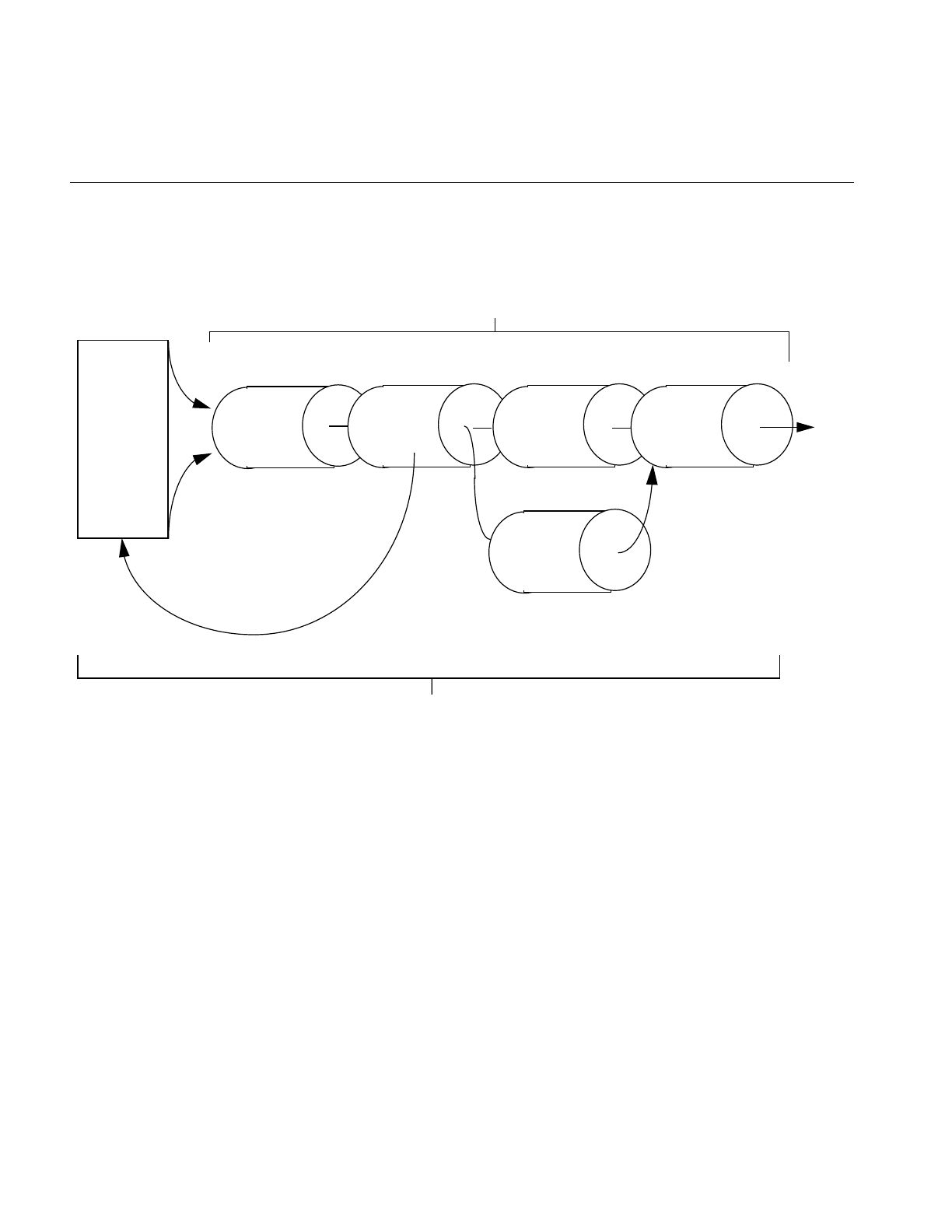
376
Appendix G: Using the Electronic Light Table
Figure G-1 ELT image processing pipeline
Each stage of the ELT pipeline has the following purpose:
R Sets contain the image data at different levels of reduction.
DeWarp changes the perspective or corrects any image imperfection caused by
the image capturing mechanism.
RotZoom allows you to zoom or rotate the image. ELT selects the correct R-set to
input for each specified zoom value.
Convolve allows you to sharpen or blur the image.
Histogram feeds data into the LUT to adjust pixel luminance dynamically
according to the overall brightness of the displayed image.
LUT adjusts pixel luminance and color dynamically.
DeWarp Convolve
Histogram
LUT
RotZoom
R Sets
R0
R1
R2
R3
R4
R5
R6
R7
.
.
.
ilChain
ELT
ELT controls input
so the correct R-set
is used for a specific
rotzoom value
Display

Understanding How ELT Works
377
DeWarping the Image
The output pages are subdivided into fine meshes of a user-defined size. The default size
is a uniform, 10 X 10 mesh. The dewarp function composited with an affine
transformation is used to compute the coordinates of the input image. Using a fine mesh
with a high order resampling method, either bilinear or bicubic interpolation, creates
high quality dewarped images.
The member functions used to get and set both dewarp and mesh parameters are
ilStatus setWarp(ilELTrset* rset, const ilWarp* Xyc);
ilStatus getWarp(ilELTrset* rset, const ilWarp*& Xyc) const;
void setMaxMeshSize(int n);
int getMaxMeshSize() const;
ilStatus setResampType(ilResampType rs);
rset allows the application to reset the warp operator, Xyc is the dewarp function, n is the
maximum mesh size, and rs is either ilNearNb, ilBiLinear or ilBiCubic.
RotZooming the Image
The RotZooming operator enables fluid zoom, rotation, and translation of images. You
use the following ilELTImg member functions to control the view manipulation:
void setAngle(float ang);
float getAngle() const;
void setZoom(float s);
float getZoom() const;
void setHorizontalFlip(int flip);
int getHorizontalFlip();
void setVerticalFlip(int flip);
int getVerticalFlip(); }
where ang is the angle to display the image at, myELT is the ilELTImg object, s is the zoom
level, and flip indicates that the image should be flipped.
Convolving the Image
The ilELTImg class also provides member functions for convolving an image using either
general or separable kernels.

378
Appendix G: Using the Electronic Light Table
void setConvKernel(ilKernel* inputKernel);
const ilKernel* getConvKernel() const;
where inputKernel is the kind of convolution kernel you want to set. The kernel may be
either an ilKernel- or ilSepKernel-type of object.
Kernels with sizes of 3 X 3, 5 X 5, or 7 X 7 can be accelerated on the Impact, RealityEngine,
and InfiniteReality platforms. Separable convolutions run faster than general
convolutions.
Collecting Histogram Data
Histogram data is used by the look-up table operator, iflLutImg, to automatically adjust
the color and luminance of each pixel to spread the range of luminance in an image over
the number of bits per pixel in the output image. Transposing the luminance values in
this way has the effect of making dark images brighter and overly-bright images darker.
Histogram data is collected over a user-definable number of frames. If, for example, the
sampling interval is defined as thirty frames, data is collected over the first 28 frames,
during the display of the 29th frame the data is read out of the hardware, and during the
30th frame the information is sent to the LUT. In general, data is collected over the
sampling interval minus two frames (samplingInterval - 2).
Collecting and processing histogram data incurs a performance drawback. To alleviate
this problem, you can specify the histogram sampling interval. Performance improves if
the histogram data is sampled infrequently. The possible consequence of a long sampling
interval, however, is sudden adjustments to luminance and color. The default update
interval is once per 30 frames.
Use the following ilELTImg member functions to control the sampling rate:
ilStatus setHistPeriod(int numFrames);
int getHistPeriod() const;
where numFrames is the number of frames that pass between one sampling and another.
Use the following functions to specify the number of bins used to compute the histogram
tables:
ilStatus setHistNbins(int num);
int getHistNbins() const;

Understanding How ELT Works
379
where num is the number of bins.
All channels have the same number of bins and the number of bins must be a power of
two.
Use the following functions to process the histogram tables that are returned:
ilStatus setHistCallback(const ilCallback* callback = NULL);
ilCallback* getHistCallback() const;
Dynamically Adjusting the Image
The look-up table (LUT) adjusts the luminance and color values of each pixel
dynamically. The LUT can adjust the luminance and color values on a frame-by-frame
basis. The actual adjustment is determined by how often the histogram samples the
image. The default is once every 30 frames.
The process of Dynamic Range Adjustment (DRA) takes the darkest and brightest
luminance values in the image and scales them over the number of bits per pixel in the
output image. This has the effect of making dark images bright and overly-bright images
darker.
The Tonal Transfer Characteristic (TTC) changes the image colors. These changes can
either correct color errors introduced by a camera mechanism or create false colors for
the purpose of examining image details.
The member functions used to get and set DRA and TTC are
ilStatus setLookUpTable(const iflLut& lut);
const iflLut* getLookUpTable() const;
where lut contains information from the lookup table.
DeWarping the Image Data
Before displaying the image manipulated by the ELT chain, you can add vectors, shaded
surfaces, or text on top of the images by using the callback functions provided by
ilELTImg and ilDisplay. Four callbacks are provided in the ilELTImg class for
•adjusting the contrast

380
Appendix G: Using the Electronic Light Table
•computing the bounding box
•generating triangle meshes
•deleting buffer resources
The callbacks that adjust the contrast are discussed in “Collecting Histogram Data” on
page 378. The other callback functions include
void setBBoxCallback(const ilCallback* callback = NULL);
ilCallback* getBBoxCallback() const;
void setTmeshCallback(const ilCallback* callback = NULL);
ilCallback* getTmeshCallback() const;
void setTmeshDelCallback(const ilCallback* callback = NULL);
ilCallback* getTmeshDelCallback() const;
The bounding box callback returns the vertices of the input space. If NULL is passed into
the setBBoxCallback() function, the default bounding box calculations method is used.
The mesh callbacks generate the triangle mesh necessary to dewarp an image. If NULL
is passed into the setTmeshCallback() function, the default Tmesh calculations method
is used.
You can either delete allocated memory for the Tmesh explicitly using
setTmeshDelCallback(), or let it deallocate itself automatically when all processing
associated with the callback is complete.
Enabling and Disabling Operators
You can enable or disable most of the operators in the ELT chain using the following
functions:
void enableHistogram(int enable = TRUE);
void enableConv(int enable=TRUE);
void enableLut(int enable=TRUE);
You can make sure the operators are enabled using the following functions:
void isHistEnabled();
void isConvEnabled();
void isLutEnabled();

Setting Operator Values
381
In addition to enabling and disabling operators, you can set their values.
Setting Operator Values
Before you enable any of the operators in an ELT chain, you must specify parameters for
them. For several of the operators, you can only set their values by using ilELTImg
member functions, such as setConv(). Other operator values can be set using the
ilELTImg constructor.
ilELTImg(ilImage* img=NULL, float minZoom=0.5,
float maxZoom=8.0,ilWarp_2d* warp=NULL, int isR0=TRUE,
void* rsetInfo=NULL);
In the constructor, img represents the input image; generally, this is the R0 image.
minZoom and maxZoom specify the minimum and maximum values of the zoom
range.These parameters often correspond to the range of images in the R-set. The warp
argument specifies the two-dimensional maps used to dewarp the image from the 1.0X
plane coordinates to the R-set’s image plane coordinates. The isR0 argument specifies
whether or not the image is the R0 image. Finally, the rsetInfo is a pointer to user-specific
R-set image data. ilELTImg’s member function, getRsetInfo() can use this information.
Understanding Accelerated Performance
The ELT takes advantage of three processes to accelerate image manipulation processing:
•look-ahead algorithms
•hardware implementation of operator functions
•reprocess the image only when there is a change in operator value
This section looks at each of these processes.
Look-ahead Algorithms
ELT implements look-ahead algorithms that accelerate the roaming and zooming
operations carried out in the ELT chain. The ELT uses one extra page border surrounding
the display window for look-ahead processing. Internally, texture memory, used for
intermediate buffers, is allocated in powers of two. For example, if a 1K by 1K space is

382
Appendix G: Using the Electronic Light Table
allocated as the intermediate, internal buffer, the maximum windows size is 896 by 896
because the look-ahead page border takes up 128 pixels (2 X 64) in each dimension.
You can enable or disable the look-ahead mechanisms using the following functions:
void enableRoamLookAhead(int enable = TRUE);
void enableZoomLookAhead(int enable = FALSE);
By default, the roaming look-ahead mechanism is enabled and the zooming look-ahead
mechanism is disabled. The default values are appropriate if the user will roam but not
zoom. If the user will zoom without roaming, it is better to enable the zoom look-ahead
and disable the roam look-ahead mechanism. If the user will zoom and roam, both
look-ahead mechanisms should be enabled. In this case, however, the performance of
one look-ahead mechanism may suffer because of the processing of the other look-ahead
mechanism.
You can make sure the look-ahead algorithm is enabled by using the following functions:
void isRoamLookAheadEnabled();
void isZoomLookAheadEnabled();
Hardware Acceleration
You can use an ELT application to view and manipulate an image in real time partly
because the manipulation processing is carried out in specialized hardware. You can turn
off this functionality using the following function, however, the performance of your ELT
application will be severely impacted.
void enableFastPath(int enable=TRUE) {fastPath=enable;
setAltered();}
You can make sure the hardware implementation is enabled by using the following
function:
int isFastPathEnabled();
Image Size
Although there is no size limit for the input image, images are stored and processed
internally in 64 X 64 tiles.

Choosing a Display in ELT Applications
383
Images are most often saved in multiple magnifications. Together, all the images at
different magnifications are called a Reduced Resolution Data Set, or R-set. If the original
image is named R0, R1 is generally R0 minimized two times; R2 is R1 minimized two
times, and so on. Each of these minimizations can be filtered for optimal results. When
the user zooms from one magnification to another, the ELT operator actually chooses the
appropriate R-set to input to the ELT pipeline. R-sets often contain seven different
magnifications of the original image.
Choosing a Display in ELT Applications
The output of the ilELTImg operator can be attached to an ilView object to display a
single image, multiple images, or a stereo display. Single and multiple image displays are
implemented using ilDisplay and ilView objects. Stereo views are implemented using
ilStereoView, a derived class of ilView, on RealityEngine and InfiniteReality platforms.
ilStereoView renders left images to the left buffer and right images to the right buffer. The
images are displayed alternately to create a three-dimensional image when viewed
through special glasses.
Creating an ELT Application
The software distribution includes a full-blown example of an ELT application called
ilChain in /usr/share. This section presents a simplified example of an ELT application. It
is based on the example code, ilrzview.c++, found in /usr/share.
This example implements the following user interface:
•Dragging with the left mouse button moves the view in the display.
•Dragging with the center mouse button moves the image in the view.
•Using the left and right arrows on the keyboard rotate the image.
•Using the up and down arrows on the keyboard zoom the image.
Example G-1 uses the following steps to implement an ELT application:
1. Parse the command line arguments.
2. Open an image file.

384
Appendix G: Using the Electronic Light Table
3. Instantiate an ilELTImg object.
4. Create an X connection and open a display.
5. Create an X window viewer.
6. Implement the user interface.
Example G-1 Coding an ELT Application
#include <stdlib.h>
#include <string.h>
#include <getopt.h>
#include <stdio.h>
#include <X11/Xlib.h>
#include <X11/keysym.h>
#include <il/ilFileImg.h>
#include <il/ilViewer.h>
#include <il/ilConfigure.h>
#include <ifl/iflMinMax.h>
#include <il/ilELTImg.h>
#include <il/ilBlurImg.h>
void
main (int argc, char* argv[])
{
// Step 1: Process the command line arguments
int usage = 0, sizePres = FALSE, attr = 0, autoAbort = FALSE;
int compSize = 8;
int blur = FALSE;
iflSize winsize;
ilResampType resamp = ilBiLinear;
int c;
while ((c = getopt(argc, argv, “bnlcads:”)) != -1) {
switch (c) {
case ‘b’:
blur = TRUE;
break;
case ‘n’:
resamp = ilNearNb;
break;
case ‘l’:
resamp = ilBiLinear;
break;

Creating an ELT Application
385
case ‘c’:
resamp = ilBiCubic;
break;
case ‘a’:
autoAbort = TRUE;
break;
case ‘d’:
compSize = 4;
attr |= ilVisDoubleBuffer;
break;
case ‘s’:
sizePres = TRUE;
sscanf(optarg, “%d,%d”, &winsize.x, &winsize.y);
break;
case ‘?’:
usage = 1;
break;
}
}
if (usage || argc-optind != 1) {
printf(“autoAbort, doubleBuffer, Size\n”);
printf(“%s [-ad -s <size x,y>] <image-file>\n”,
argv[0]);
exit(0);
}
// Step 2: Open an image file.
ilFileImg img(argv[optind]);
if (img.getStatus() != ilOKAY) {
char buf[400];
rintf(stderr, “Couldn’t open image file %s: %s\n”, argv[optind],
ilStatusToString(img.getStatus(), buf, sizeof(buf)));
exit(0);
}
// Step 3: Instantiate an ilELTImg object.
ilELTImg myELT(image, .5, 8));
// Step 4: Get an X connection and open a display.
if (!sizePres) img.getSize(winsize, iflLowerLeftOrigin);

386
Appendix G: Using the Electronic Light Table
ilImage* image = &img;
if (blur) image = new ilBlurImg(image);
// Get display connection and clamp window size
Display* dpy = XOpenDisplay(NULL);
int screen = DefaultScreen(dpy);
winsize.x = iflMin(winsize.x, DisplayWidth(dpy, screen));
winsize.y = iflMin(winsize.y, DisplayHeight(dpy, screen));
// Step 5: Create an X window viewer.
ilViewer viewer(dpy, winsize.x, winsize.y, attr, compSize);
if (autoAbort) {
viewer.enableQueueing();
viewer.enableAutoAbort();
}
ilView* view = viewer.addView(&myELT, ilClip|ilCenter);
view->setAutoCenter();
// Step 6: Implement the user interface.
int done=FALSE;
float zoom=1;
int angle=0;
int movieRunning = FALSE;
while (!done) {
XEvent e;
if (movieRunning) {
if (!XCheckWindowEvent(dpy, viewer.getWindow(), -1, &e)) {
int z = view->getZ() + 1;
view->setZ(z);
viewer.paint();
continue;
}
}
else
XNextEvent(dpy, &e);
switch (e.type) {
case KeyPress:

Creating an ELT Application
387
switch(XLookupKeysym(&e.xkey, 0)) {
// center the view in the viewer
case XK_Home:
viewer.display(NULL, ilCenter|ilClip);
break;
// control-Q and escape exit the program
case XK_q:
if (!(e.xkey.state&ControlMask))
break;
/*FALLTHROUGH*/
case XK_Escape:
done = TRUE;
break;
case XK_s:
movieRunning = FALSE;
break;
// flip the image
case XK_h:
viewer.abort();
myELT.setHorizontalFlip(!myELT.getHorizontalFlip());
viewer.paint();
break;
case XK_v:
viewer.abort();
myELT.setVerticalFlip(!myELT.getVerticalFlip());
viewer.paint();
break;
// zoom and rotate the image
case XK_Up:
viewer.abort();
myELT.setZoom(zoom *= 1.2);
viewer.paint();
break;
case XK_Down:
viewer.abort();
myELT.setZoom(zoom /= 1.2);
viewer.paint();
break;
case XK_Right:
viewer.abort();
myELT.setAngle(angle -= 15);
viewer.paint();
break;
case XK_Left:

388
Appendix G: Using the Electronic Light Table
viewer.abort();
myELT.setAngle(angle += 15);
viewer.paint();
break;
}
break;
case DestroyNotify:
viewer.destroyNotify();
done = TRUE;
break;
default:
viewer.event(&e);
break;
}
}
}
Understanding the ilELTImg API
The ilELTImg class has an extensive set of methods. The ilELTImg manpage contains an
extended discussion of each method. Table G-1 summarizes each method.
Table G-1 Methods in ilELTImg
Method Description
ilELTImg ilELTImg(ilImage* img=NULL, float minZoom = 0.5,
float maxZoom = 8.0,ilWarp* warp = NULL,
int isR0 = TRUE, void* rsetInfo = NULL)
Constructor for the class.
addRset ilELTrset* addRset(ilImage* img, float minZoom,
float maxZoom, ilWarp* warp, int isR0 = FALSE,
void* rsetInfo = NULL)
Allows the user to specify additional R-sets for
roaming.
enableConv void enableConv(int enable=TRUE)
Enables or disables the convolution operation on an
ilELTImg object.

Understanding the ilELTImg API
389
enableFastPath void enableFastPath(int enable=TRUE)
Enables or disables the special-purpose hardware
acceleration for ELT.
enableHistogram void enableHistogram(int enable = TRUE)
Enables or disables the auto histogram operation on
an ilELTImg object.
enableLut void enableLut(int enable=TRUE)
Enables or disables the table look-up operation on an
ilELTImg object.
enableRoamLookAhead void enableRoamLookAhead(int enable = TRUE)
Enables or disables the roaming look-ahead operation
on an ilELTImg object.
enableRset ilStatus enableRset(ilELTrset* rset, int enable = TRUE)
Enables or disables a selected R-set to be in effect.
enableZoomLookAhead void enableZoomLookAhead(int enable = TRUE)
Enables or disables the zooming look-ahead
operation on an ilELTImg object.
mapFromInput void mapFromInput(float& u, float& v, float& w,
float x, float y, float z)
Given a point (x, y, z) in the R0 image plane
(regardless of which R-set is currently being roamed),
compute (u, v, w) in the display plane using the
mapping specified for geometric transformation.
mapToInput void mapToInput(float& x, float& y, float& z, float u,
float v, float w)
Given a point (u, v, w) in the display plane, compute
(x, y, z) in the R0 image plane (regardless of which
R-set is currently being roamed) using the mapping
specified for geometric transformation (including
both the dewarp and the affine-transformation
functions).
Table G-1 (continued) Methods in ilELTImg
Method Description

390
Appendix G: Using the Electronic Light Table
getAngle float getAngle() const
Returns the angle of rotation (in degrees) specified for
the view.
getBBoxCallback ilCallback* getBBoxCallback() const
Returns the user-provided callback which is used to
compute the bounding box of a given output page
mapped in its input image space.
getBicubicFamily void getBicubicFamily(float& b, float& c) const
Returns the B and C terms, defining the cubic
resampling coefficients, in b and c.
getConvBias double getConvBias() const
Returns the current additive bias specified for
convolution as a double.
getConvKernel const ilKernel* getConvKernel() const
Returns the current convolution kernel.
getEnabled int getEnabled()
The returned value is comprised of one or more of the
following bit fields:
ilELTImg::ilEPdewarp is set if dewarp operation is
enabled.
ilELTImg::ilEPhist is set if auto histogram operation is
enabled.
ilELTImg::ilEPconv is set if convolution is enabled.
ilELTImg::ilEPlut is set if table look-up is enabled.
ilELTImg::ilEProam is set if roaming look-ahead is
enabled.
ilELTImg::ilEPzoom is set if zooming look-ahead is
enabled.
getHistNbins int getHistNbins() const
Returns the number of bins currently being specified
for the histogram table.
Table G-1 (continued) Methods in ilELTImg
Method Description

Understanding the ilELTImg API
391
getHistPeriod int getHistPeriod() const
Returns the number of frames between look-up table
updates; default is 30 frames.
getHistCallback ilCallback* getHistCallback() const
Returns the current histogram callback being used or
NULL if none has been defined.
getLookUpTable const iflLut* getLookUpTable() const
Returns the current lookup table being provided by
the user.
getMaxMeshSize int getMaxMeshSize() const
Returns the maximum allowable mesh size used for
geometric transformations.
getPairedImg ilELTImg* getPairedImg() const
Returns the other image of a paired image, for
example, in a stereo image.
getResampType ilResampType getResampType() const
Returns the current resampling type used in
geometric transformations.
getRset ilELTrset* getRset(ilImage* img) const
Returns an opaque handle to the R-set for the input
image, img.
getRsetChangeCallback ilCallback* getRsetChangeCallback() const
Returns the user-provided callback which indicates
when the input image to the ELT has switched from
one R-set to another.
getRsetInfo void* getRsetInfo(ilELTrset* rset) const
Returns the user-provided information about the
specified R-set. If no R-set information has been
provided, NULL is returned.
getRsetZoomRange ilStatus getRsetZoomRange(ilELTrset* rset,
float& minZoom, float& maxZoom)
Gets the scaling range covered by the specified R-set.
Table G-1 (continued) Methods in ilELTImg
Method Description

392
Appendix G: Using the Electronic Light Table
getTmeshCallback ilCallback* getTmeshCallback() const
Returns the user-provided callback which a generates
triangle mesh for a given output page.
getWarp ilStatus getWarp(ilELTrset* rset, const ilWarp*& func)
const
Returns rset’s dewarp function in func.
getZoom float getZoom() const
Returns the current display scale being specified.
isConvEnabled int isConvEnabled()
Returns TRUE if convolution is enabled for the
current operation; FALSE, otherwise.
isFastPathEnabled int isFastPathEnabled()
Returns TRUE if special purpose hardware
acceleration is enabled for the current operation;
FALSE, otherwise.
isHistEnabled int isHistEnabled()
Returns TRUE if auto histogram is enabled for the
current operation; FALSE, otherwise.
isLutEnabled int isLutEnabled()
Returns TRUE if table look-up is enabled for the
current operation; FALSE, otherwise.
isRoamLookAheadEnabled int isRoamLookAheadEnabled()
Returns TRUE if roaming look-ahead is enabled for
the current operation; FALSE, otherwise.
isZoomLookAheadEnabled int isZoomLookAheadEnabled()
Returns TRUE if zooming look-ahead is enabled for
the current operation; FALSE, otherwise.
removeRset ilStatus removeRset(ilELTrset* rset)
Removes the specified R-set from the roaming
operation.
Table G-1 (continued) Methods in ilELTImg
Method Description

Understanding the ilELTImg API
393
setAngle void setAngle(float ang)
Changes the rotation angle to that specified by the
argument, ang, which is specified in degrees.
setBBoxCallback void setBBoxCallback(ilCallback* callback = NULL)
Sets up a callback to compute the bounding box of a
given output page mapped in its input image space.
setBicubicFamily void setBicubicFamily(float b=1., float c=0.)
Specifies the B and C terms which define the bicubic
resampling coefficients.
setConvBias ilStatus setConvBias(double biasVal)
Sets the additive bias applied to all pixels after the
convolution operation.
setConvKernel void setConvKernel(ilKernel* inputKernel,
int doClamp=TRUE)
Sets the convolution kernel.
setHistNbins ilStatus setHistNbins(int num)
Sets the number of bins in the histogram table.
setHistPeriod ilStatus setHistPeriod(int numFrames)
Sets the number of frames between LUT updates.
setHistCallback ilStatus setHistCallback(ilCallback* callback =
NULL)
Provides a histogram callback.
setLookUpTable ilStatus setLookUpTable(const iflLut& lut)
Sets a new look-up table to be downloaded to the
graphics system.
setMaxMeshSize void setMaxMeshSize(int N)
Sets the maximum allowable mesh size for geometric
transformation to be NxN pixels.
setPairedImg void setPairedImg(ilELTImg* pairedImg)
Sets the other image of an image pair (i.e., stereo pair).
Table G-1 (continued) Methods in ilELTImg
Method Description

394
Appendix G: Using the Electronic Light Table
setResampType ilStatus setResampType(ilResampType rs)
Selects the resampling type to be used.
setRsetChangeCallback void setRsetChangeCallback(ilCallback* callback =
NULL)
Provides a R-set change callback.
setRsetInfo ilStatus setRsetInfo(ilELTrset* rset, void* rsetInfo =
NULL)
Sets the user-specified R-set information for the given
R-set handle.
setRsetZoomRange ilStatus setRsetZoomRange(ilELTrset* rset,
float minZoom, float maxZoom)
Sets the scaling range covered by the specified R-set.
setTmeshCallback void setTmeshCallback(ilCallback* callback = NULL)
Provides a triangle mesh generation callback.
setTmeshDelCallback void setTmeshCallback(ilCallback* callback = NULL)
Sets up a callback to clean up triangle lists after the
system finishes drawing them.
setWarp ilStatus setWarp(ilELTrset* rset, const ilWarp* func)
Sets rset’s dewarp function to be func.
setZoom void setZoom(float scale)
Changes the display scale to scale.
Table G-1 (continued) Methods in ilELTImg
Method Description

395
Appendix H
H. Results of Operators
This appendix presents examples in the following sections of all the operators that give
visible results:
•“Color Conversion” on page 396
•“Arithmetic and Logical Transformations” on page 397
•“Geometric Transformations” on page 400
•“Spatial Domain Transformations” on page 401
•“Edge Detection” on page 402
•“Frequency Domain Transformations” on page 404
•“Radiometric Transformations” on page 405
•“Combining Images” on page 407
For more information on using these operators and what effect they have on image data,
see Chapter 4, “Operating on an Image.” More specific information on how to apply each
operator is located in its header file and in its reference page.
Original, unprocessed images are presented where necessary. Some images combine two
original images. These images are either reversed copies of the same image or two
extremely similar images.
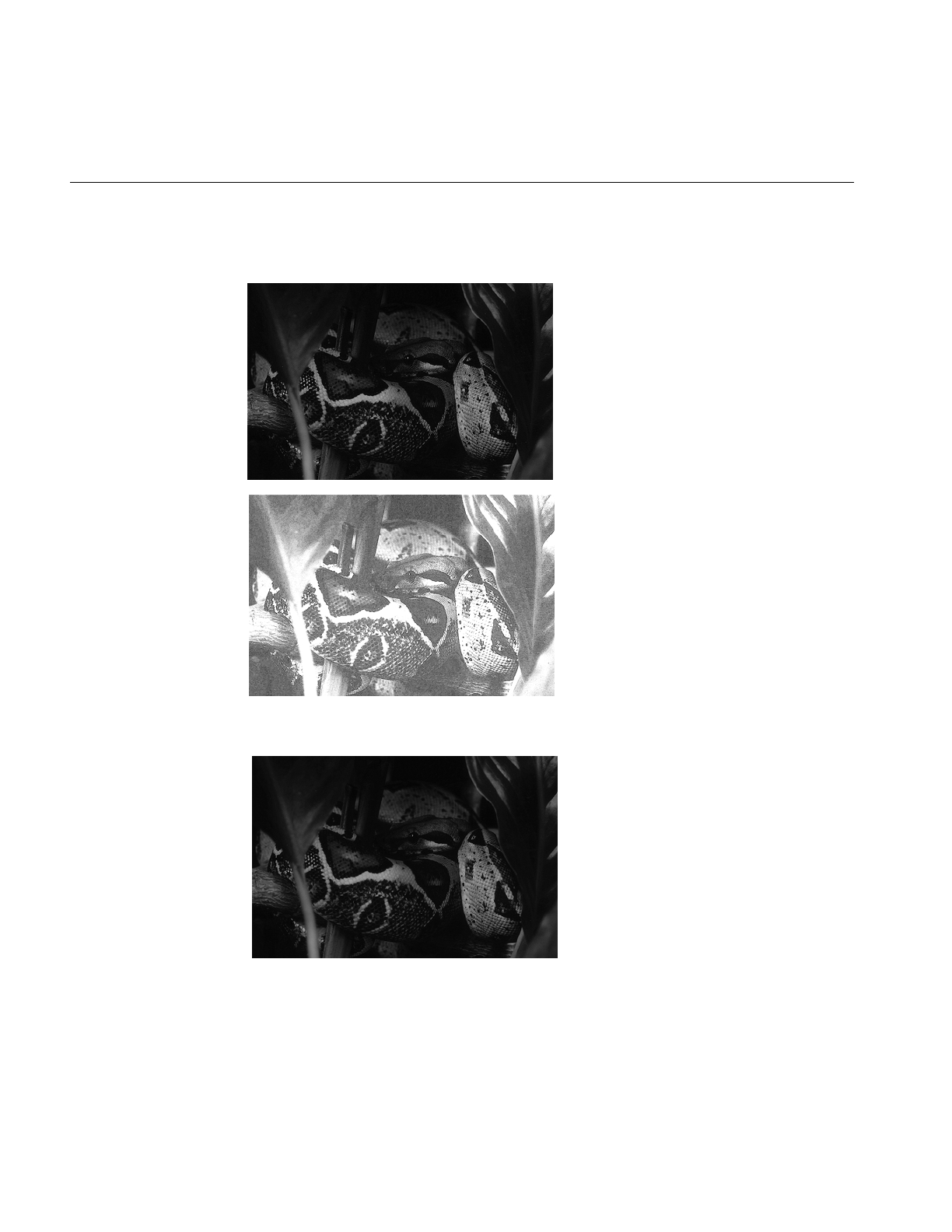
396
Appendix H: Results of Operators
Color Conversion
Figure H-1 ilFalseColorImg
Figure H-2 ilGrayImg
.
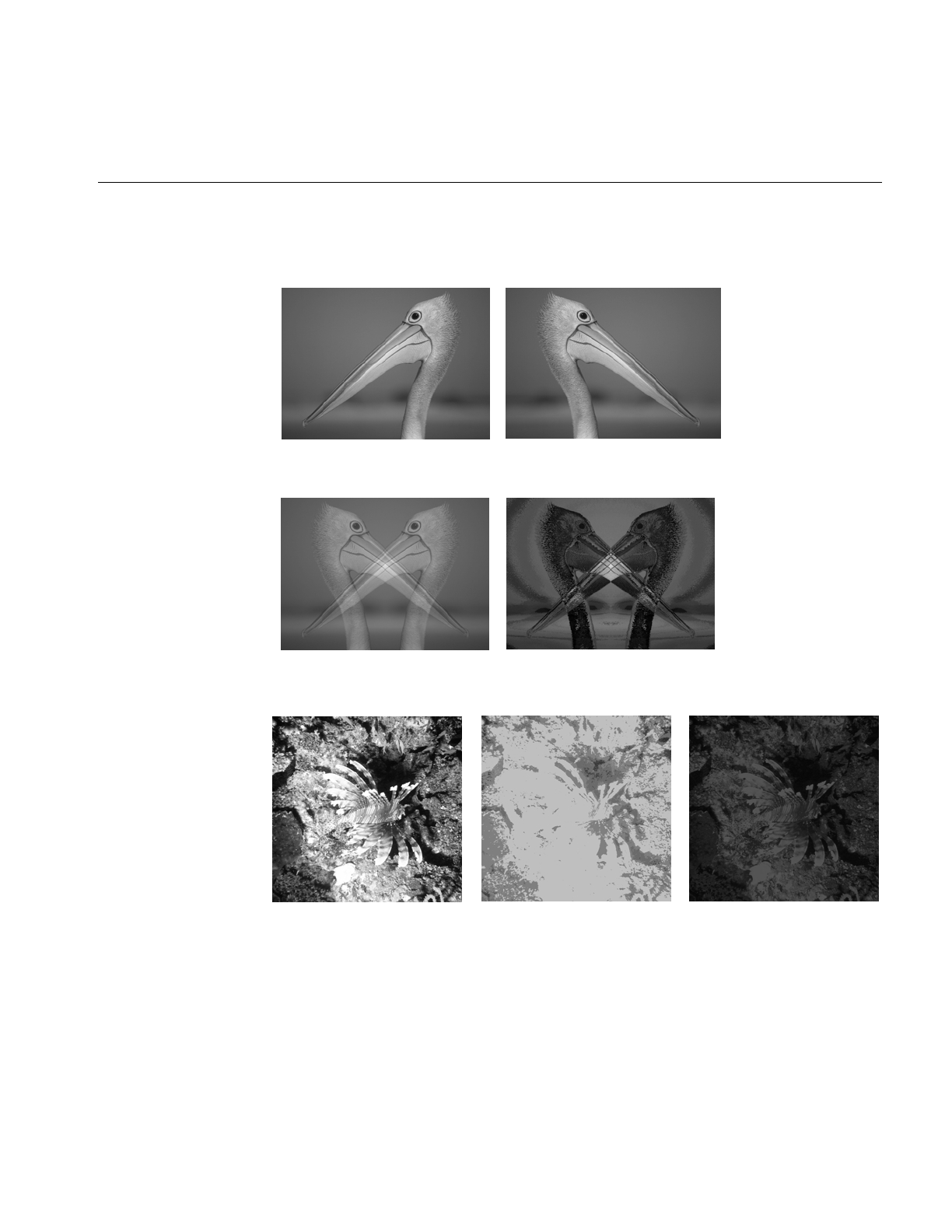
Arithmetic and Logical Transformations
397
Arithmetic and Logical Transformations
Figure H-3 Original Image and Flipped Image
Figure H-4 ilAddImg and ilAndImg
Figure H-5 ilDivImg
Original Square Root of Original Original and Square Root Divided
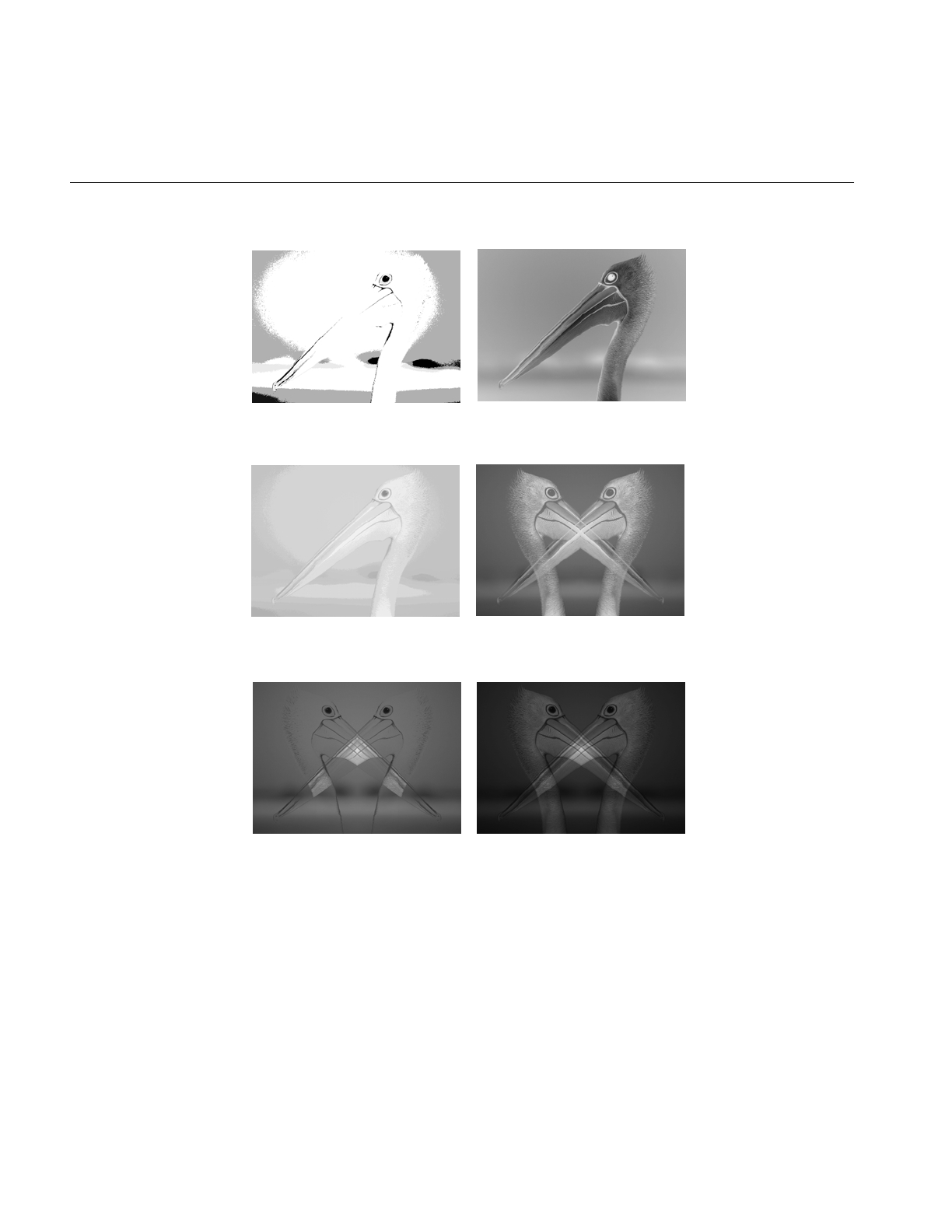
398
Appendix H: Results of Operators
Figure H-6 ilExpImg and ilInvertImg
Figure H-7 ilLogImg and ilMaxImg
Figure H-8 ilMinImg and ilMultiplyImg
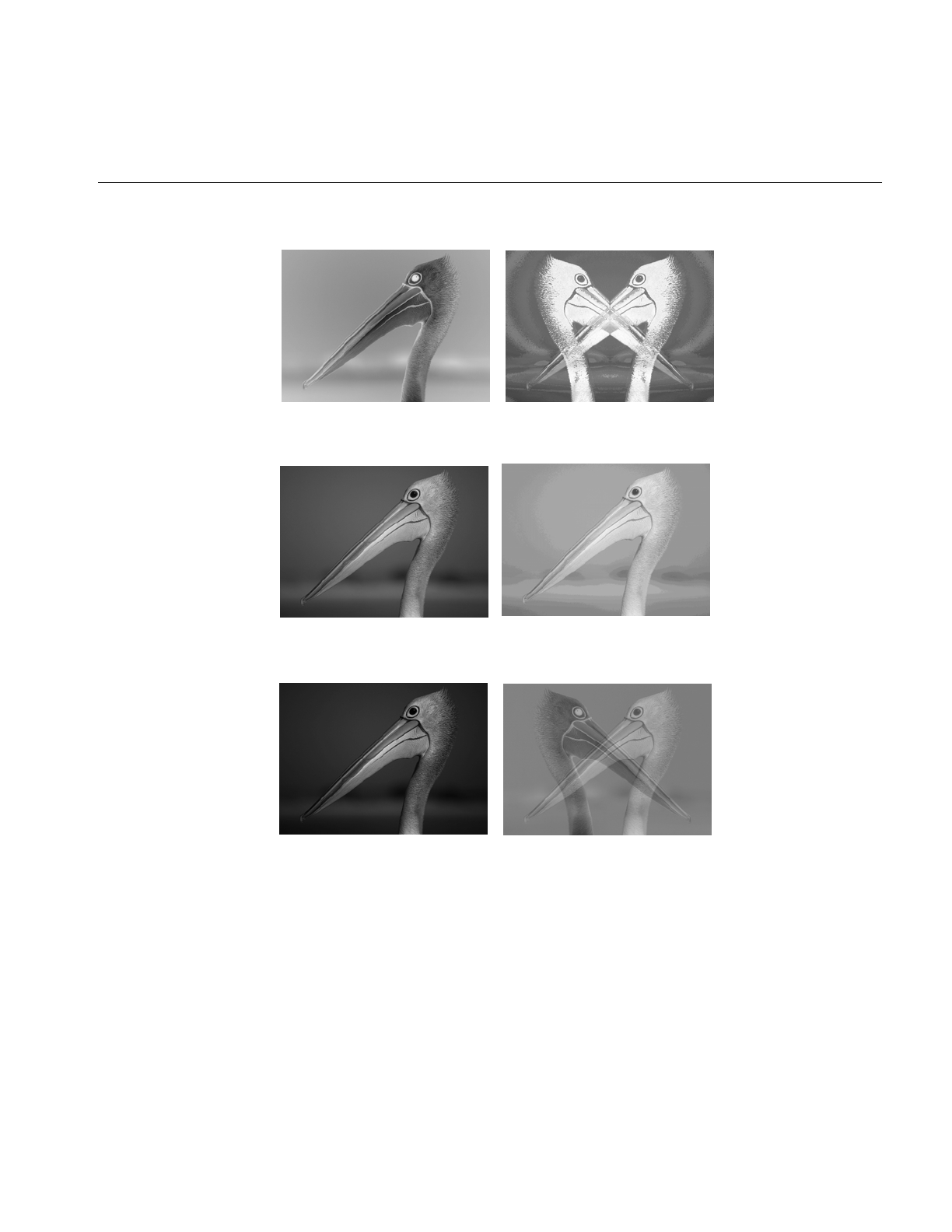
Arithmetic and Logical Transformations
399
Figure H-9 ilNegImg and ilOrImg
Figure H-10 ilPowerImg and ilSqRootImg
Figure H-11 ilSquareImg and ilSubtractImg
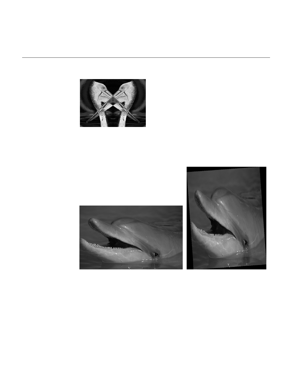
400
Appendix H: Results of Operators
Figure H-12 ilXorImg
Geometric Transformations
Figure H-13 Original and ilRotZoomImg
.
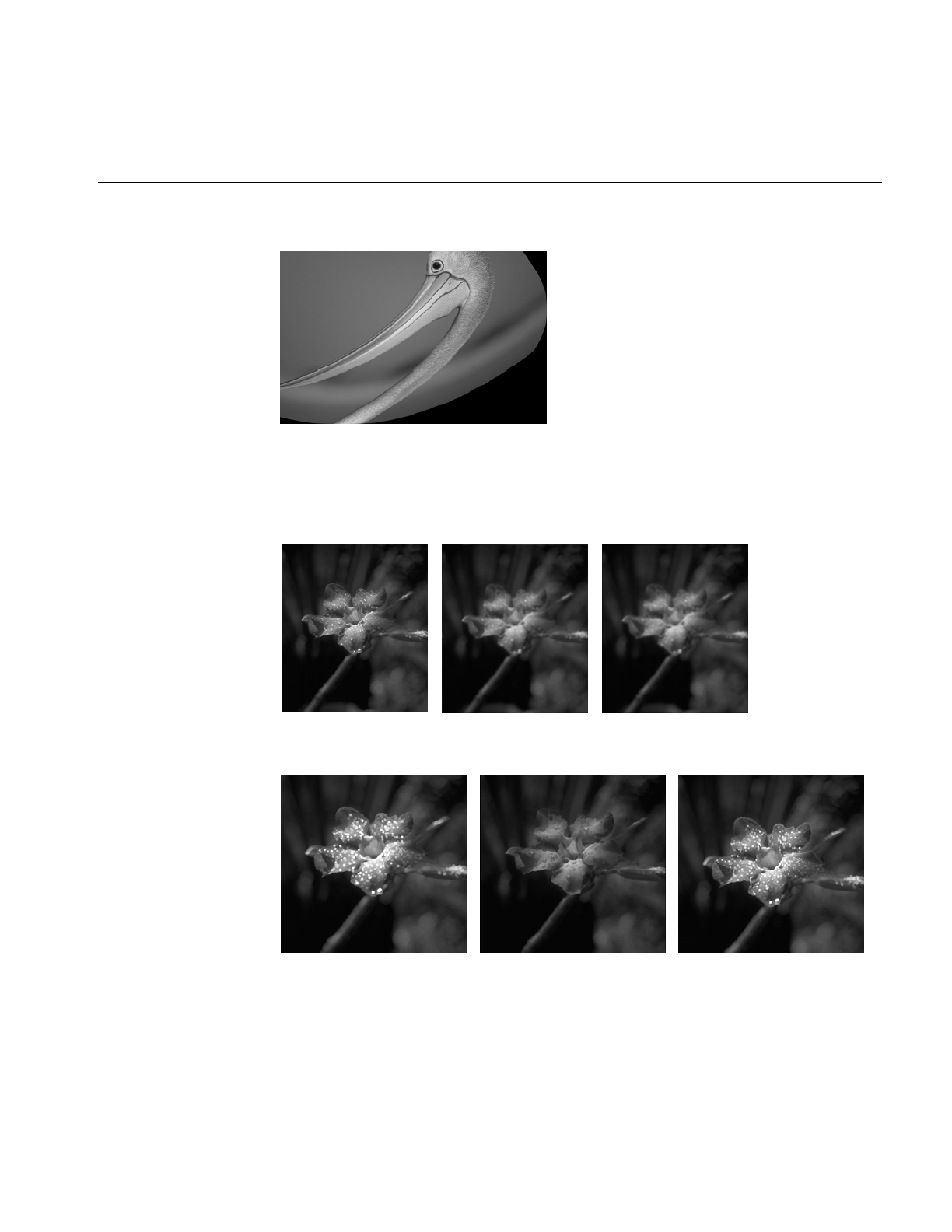
Spatial Domain Transformations
401
Figure H-14 ilWarpImg
Spatial Domain Transformations
Figure H-15 Original, ilBlurImg and ilGBlurImg
Figure H-16 ilDilateImg, ilErodeImg, and ilMaxFltImg
.
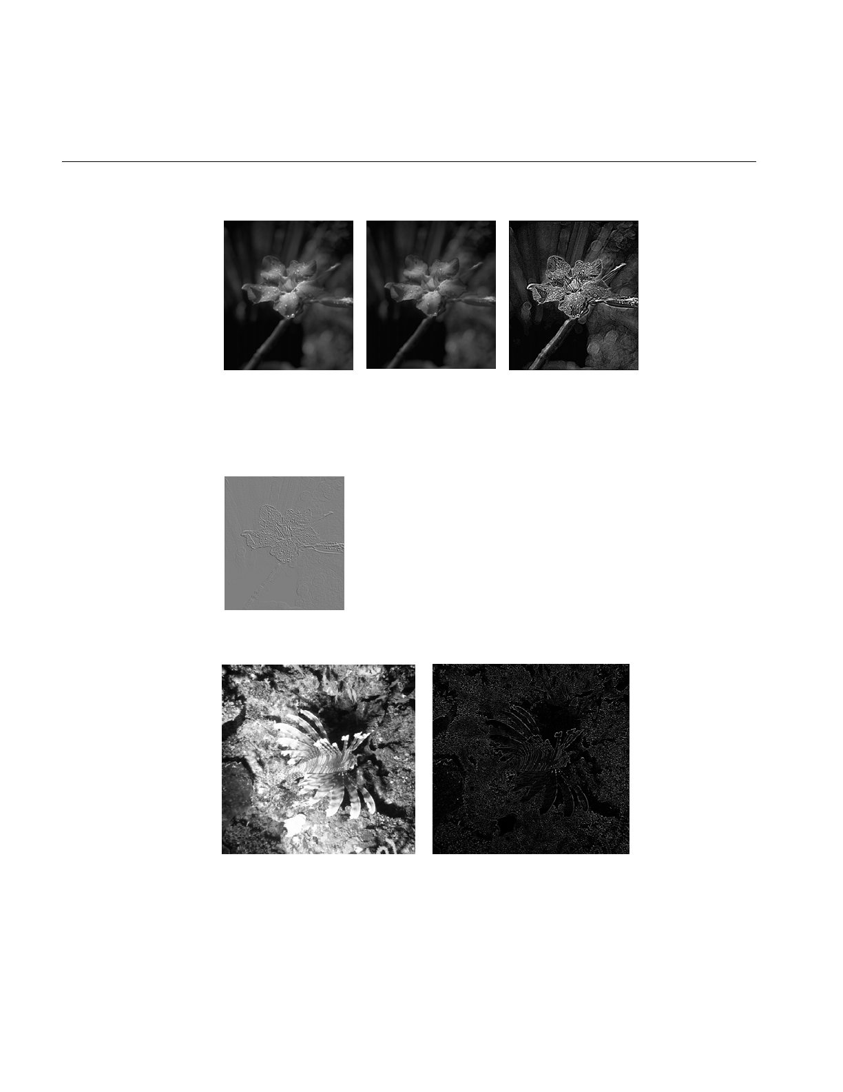
402
Appendix H: Results of Operators
Figure H-17 ilMedFltImg, ilMinFltImg, and ilSharpenImg
Edge Detection
Figure H-18 ilCompassImg
Figure H-19 ilLaplaceImg (original and filtered image)
.
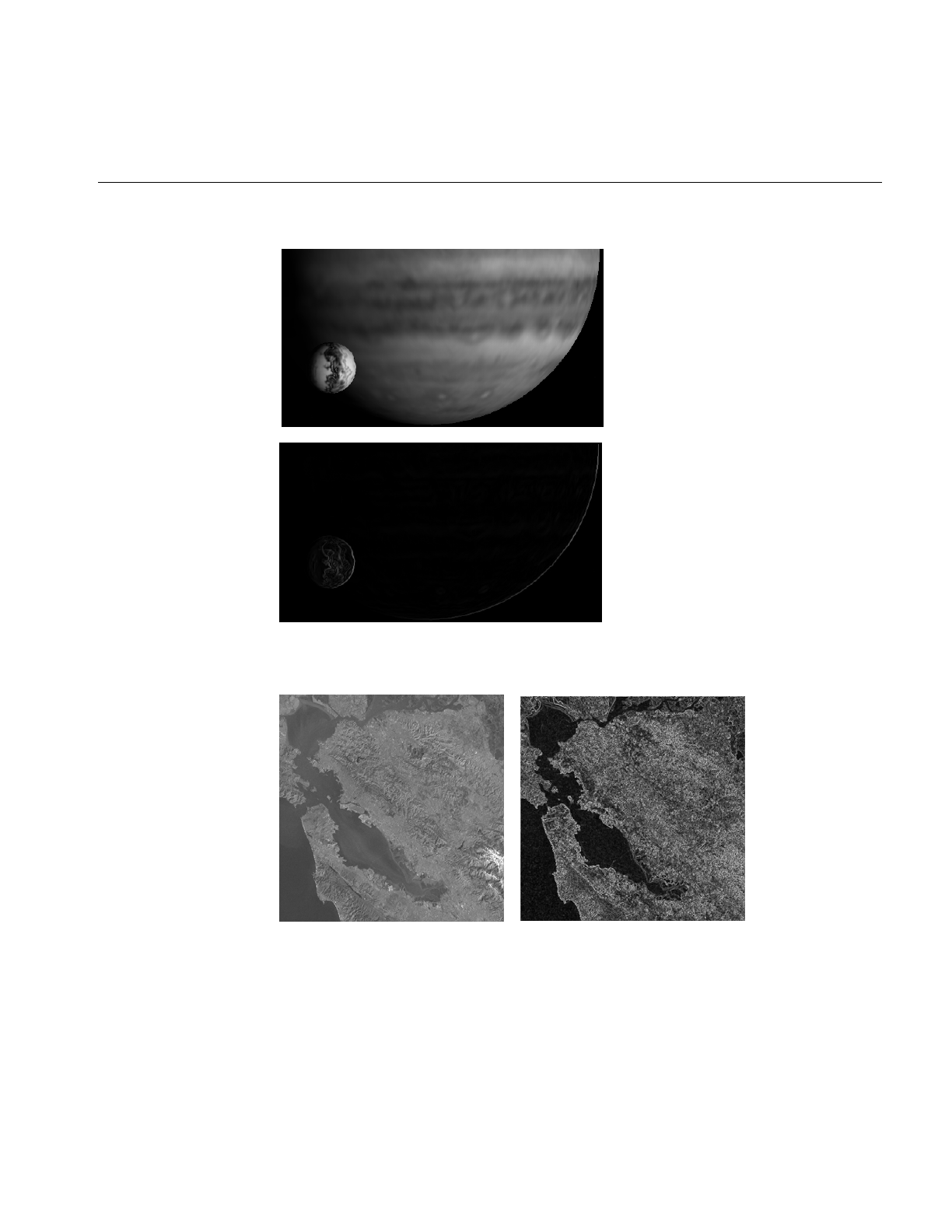
Edge Detection
403
Figure H-20 ilRobertsImg (original and filtered image)
Figure H-21 ilSobelImg (original and filtered image)
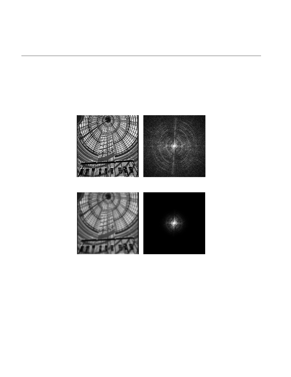
404
Appendix H: Results of Operators
Frequency Domain Transformations
The frequency domain transformations are of limited interest as illustrations. For the
purposes of this appendix, one example is shown. In the example, an original image is
presented along with its appearance in the frequency, or Fourier domain, and the filtered
resultant image is shown in both the spatial and frequency domains.
Figure H-22 ilFGaussFiltImg
Frequency Domain
Original
Frequency Domain
Filtered Original
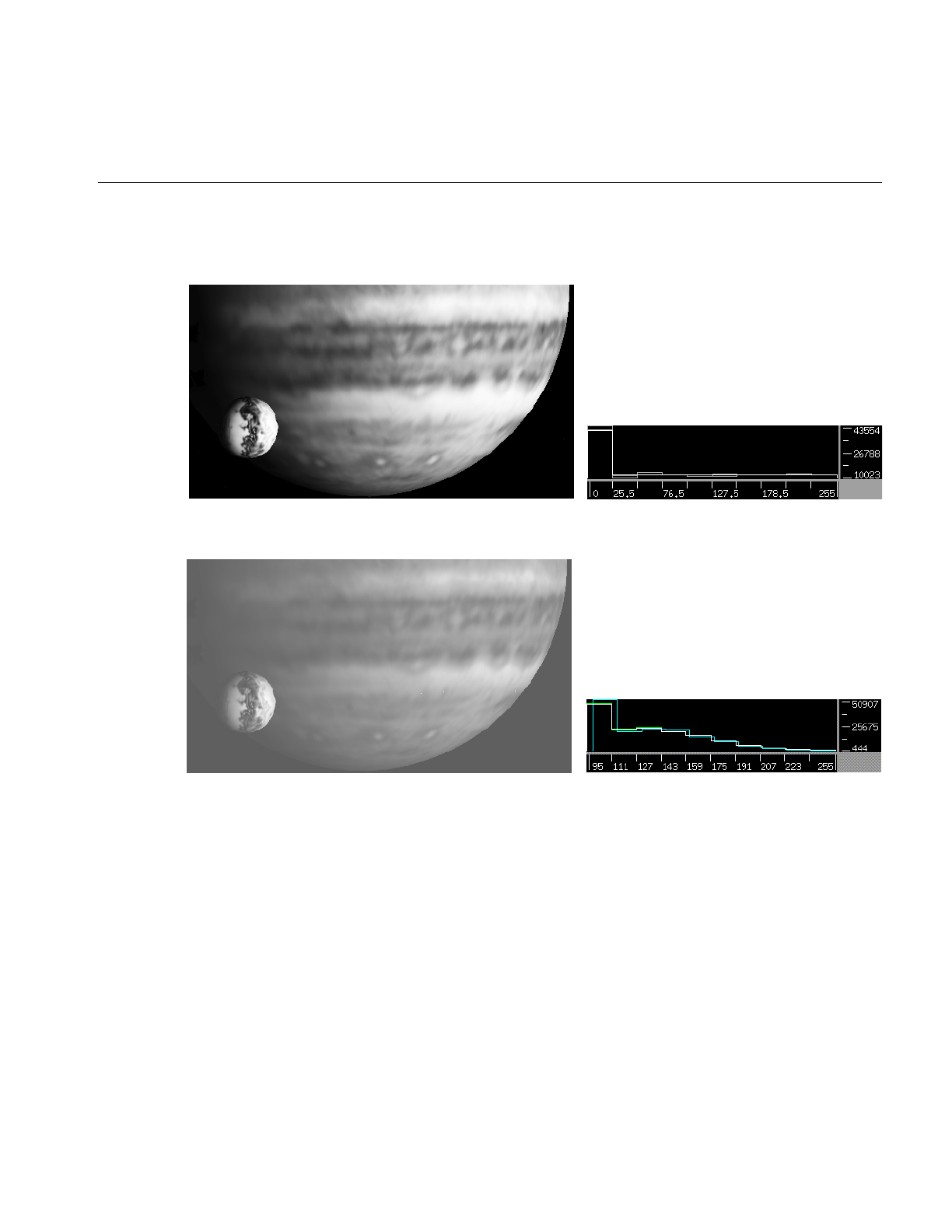
Radiometric Transformations
405
Radiometric Transformations
Figure H-23 ilHistEqImg (filtered image and histogram)
Figure H-24 ilHistNormImg (filtered image and histogram)
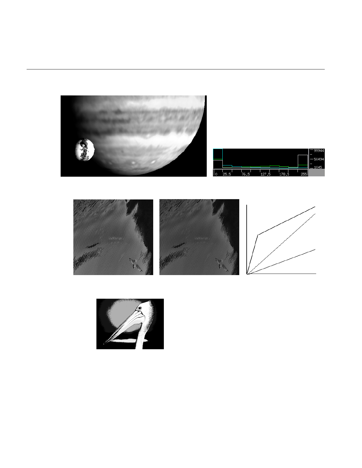
406
Appendix H: Results of Operators
Figure H-25 ilHistScaleImg (filtered image and histogram)
Figure H-26 ilLutImg (original, filtered image, and LUT editor)
Figure H-27 ilThreshImg
.
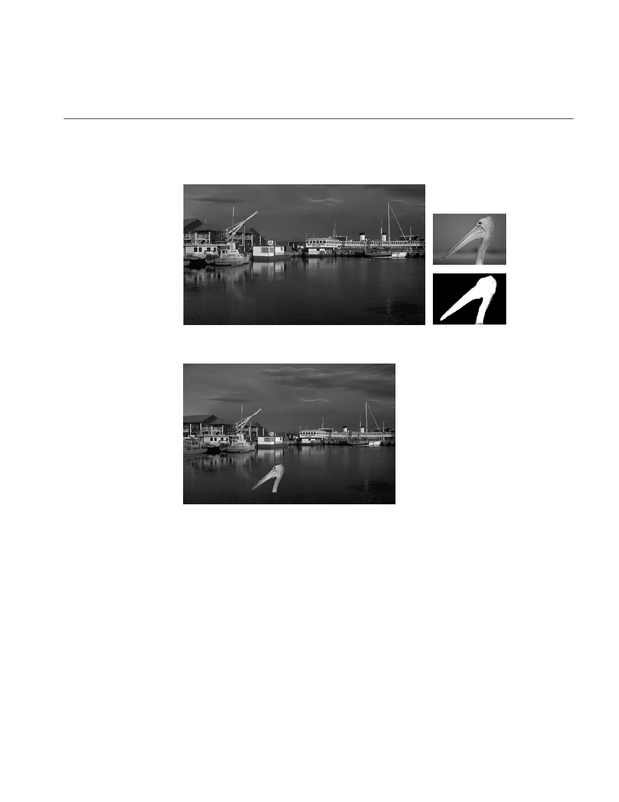
Combining Images
407
Combining Images
Figure H-28 Originals and Original Mask
Figure H-29 ilBlendImg
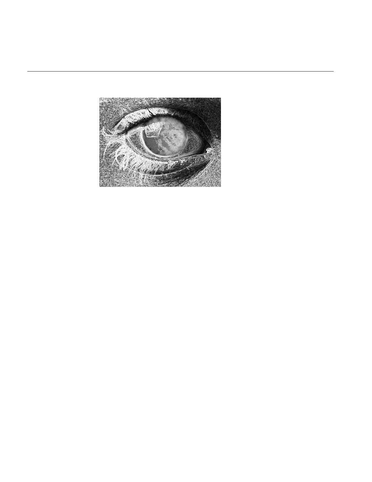
408
Appendix H: Results of Operators
Figure H-30 ilCombineImg

409
B
background
color, 172
view, 172
bias value, 95, 108, 110, 117, 119
BinBin, 116
BinGray, 116
blending images, 146
blurring an image, 109
border style, 173
breakpoint, 143
buffers, using, 253
C
cache, 32-39, 215
monitoring, 251
optimizing use of, 247
replacing pages in, 34
cache size, 248-249
affected by multi-threading, 249
default, 248
optimum, 248
calcPage(), 226, 230, 235
chain, 56
Numbers
64-bit address space, 289
A
absolute value operator, 92
accessing data, see reading, writing, or copying
addInput(), 59
addition operator, 94
addView(), 168, 177
affine transformations, 105
alignImg(), 188
aligning
images, 188
views, 185, 189
alignView(), 188, 189
allocPage(), 214
alpha value, 147
AND operator, 97
arithmetic operators, 90-97
dual-input, 94-98
single-input, 91
asynchrounous operations, 292
attributes, see image attributes
Index

410
Index
chain of operators, 17, 50
components of, 18
propagation, 59
querying, 58
reconfiguring, 57
changes, to 2.5 classes, 298
checkColorModel(), 207
checkMinMax(), 228
C interface, 9
clamp(), 227
classes, new in 3.0, 289
class name conversions, 308
clearAllowed(), 210
clearCenter(), 105
clearSet(), 60
clearStatus(), 22
clipping, 48
clipTile(), 48
closing a file, 342
cmplxVectorCalc(), 238
color conversion, 85-87
color-index mode, 364
color model, 25, 26, 85
determining, 26, 87
initializing when deriving, 203
color palette, 27
color saturation, 89
combining images, 146
compass operator, 118
compatibility with version 2.5, 306
compiling, 273
complex conjugate of an image, 130
compose(), 360
compression, data, 32, 75
conjugate of an image, 130
constants, 369
constant value image, 152
convolution, 108, 117, 132
coordinates, 365
initializing, 196
copying
image data, 40
tiles efficiently, 252
copyTile(), 40-44, 52, 74, 105, 252, 253
copyTile3D(), 46
copyTileCfg(), 44, 46
creating a file, 73
cross-correlation operator, 131
D
data ordering, 24-25
data type of an image, 23, 26, 363
deferred drawing, 174, 177, 191
deleteView(), 180
deriving classes, 199
dilation, 113
display(), 184, 185, 186
display facility in 3.0, 294
displaying an image, 159
display mode, 175
display operators, 184
division by zero, 95, 132
division operator, 94
for Fourier images, 131
doUserPageAlloc(), 214
drawing
area, 175
deferred, 174, 177, 191
views, 184

411
Index
E
edge detection, 117-119
edge image, 117, 118
edge mode, 107, 110, 113, 118, 119
enableMP(), 133
enumerated types, 369
for image attributes, 370
environment variable, 278
erosion, 113
error codes, 22, 366
error handling in 3.0, 295
evalUV(), 50, 104
evalXY(), 49, 104
event-handling, 168
exclusive-OR operator, 97
executeRequest, 213
execution model, 50-59
advantages, 51
exponential operator, 92
Fourier, 131
exporting data, 78
extending the IL, 199
F
FALSE, 369
faLse coloring, 88
fast Fourier transform, 120
features, new for 3.0, 288
file
access mode, 72
closing, 342
creating, 73
opening, 71
file formats, 66
filename syntax for images, 72
fillTile(), 41-46
fillTile3D(), 47
fill value, 29, 108
findEdge(), 181, 194
findPoint(), 145
findView(), 181
finishRequest, 213
FIT, 6
FIT file format, 66, 69
flags, for display operators, 175
align mode, 176
coordinate, 176
display, 176
wipe mode, 176
flipping an image, 105
flush(), 36, 214
Fourier filtering, 126
Fourier transform, 120
freePage(), 214
freqFilt(), 241
frequency domain operators, 120-132
frequency filtering, 126
G
Gaussian kernel, 109
geometric operators, 98-106
getAddressError(), 102
getAlphaRange(), 149
getAngle(), 105, 120
getBackground(), 172
getBias(), 119
getBkgd(), 154
getBorderStyle, 173

412
Index
getBreakpoints(), 145
getCacheSize(), 36
getCenter(), 105
getChained(), 59
getClassProp(), 63
getCoeff(), 102
getColorMap(), 27
getColorModel(), 25
getCompression(), 76
getCopyConverter(), 207
getCsize(), 23
getCurrentImg(), 68, 69
getDataPtr(), 80
getDataType(), 23
getDBinSize(), 134
getDMax(), 135
getDMean(), 135
getDMin(), 135
getDStart(), 134
getDStDev(), 135
getEdgeMode(), 107
getErrorColor, 177
getFileDesc(), 76
getFileMode(), 77
getFileName(), 76
getFill(), 29
getFloatProp(), 62
getHist(), 134
getImg(), 179
getInput(), 59
getInputMax(), 228
getInputMin(), 228
getIntProp(), 61
getKernelSize(), 107
getLImg(), 179
getLoc(), 183
getMaxPixel(), 30
getMaxRank(), 113
getMaxValue(), 31, 115
getMinPixel(), 30
getMinValue(), 31
getMorphType(), 117
getNbins(), 134
getNumBreakpoints(), 145
getNumChained(), 59
getNumImgs(), 68, 69, 77
getNumInputs(), 59
getNumViews(), 179
getOffset(), 94
getOrder(), 24
getOrientation(), 28, 155
getOrigin(), 107
getPage(), 52, 227
overriding when deriving, 345
getPageBorder(), 56
getPageSize(), 38
getPageSizePix(), 39
getPageSizeVal(), 39
getPixel(), 41, 45, 182
getPoint(), 145
getPolyOrder(), 102, 104
getProp(), 62
getPropSet(), 63
getPtrProp(), 62
getResampType(), 102
getRImg(), 179
getRoi(), 151, 154
getSaturation(), 90
getScaleMax(), 31
getScaleMin(), 31

413
Index
getSize(), 21, 23, 49, 175
getStart(), 158, 196
getStatus(), 22, 366
getStrides(), 47
getStrides3D(), 214
getSubTile(), 41-45
getSubTile3D(), 46, 153
getThresh(), 142
getTile(), 34, 40-43, 52, 105
getTile3D(), 46
getTotal(), 135
getValidValue(), 156
getView(), 179
getViewIndex(), 179
getVisibleArea, 164
getXImg(), 179
getXkernel(), 109
getXsize(), 23
getXYWt(), 120
getYkernel(), 109
getYsize(), 21, 23
getZ(), 178
getZoom(), 105
getZsize(), 23
GIF, 6
GIF file format, 66
gradient operators, 117
GrayBin, 116
GrayGrayFct, 116
GrayGraySet, 116
H
hardware acceleration, 55
disabling, 56
hasPages(), 39, 158
header files, 5
including, 11
high-pass filter, 128
histogram
equalization, 140
of an image, 132, 134, 136
operators, 139
scaling, 140
I
IFL, 293
iflABGR, 25
iflBGR, 25
iflBitArray, 358
iflCMY, 25, 87
iflCMYK, 25
iflColorModel, 25
iflConfig, 358
iflDataIsSigned(), 364
iflDataSize(), 73, 221, 363
iflDataType, 23
iflDataTypeFromRange(), 363
iflFile, 338
iflHSV, 25
iflInterleaved, 24
iflLut, 27, 358, 360-362
iflMax(), 364
iflMin(), 364
iflMinBlack, 25
iflMinWhite, 25
iflMultiSpectral, 25
iflOrientation, 28, 48
iflPixel, 29, 154, 358
iflRGB, 25

414
Index
iflRGBA, 25, 87
iflRGBPalette, 25
iflSeparate, 24
iflSequential, 24
iflSize, 22, 358
iflTile, 359
iflXYSfloat, 103
iflXYZCint, 219, 235
iflYCC, 25, 87
IL_ARENA_MAXUSERS, 278
IL_CACHE_FRACTION, 35, 278
IL_CACHE_SIZE, 35, 278
IL_COMPUTE_THREADS, 54, 278
IL_DEBUG, 278
IL_HW_ACCELERATE, 278
IL_MONITOR, 279
IL_MONITOR_CACHE, 251, 279
IL_MONITOR_COMPACTION, 279
IL_MONITOR_LOCKS, 279
IL_MP_ARENA_SIZE, 279
IL_MP_LOCKS, 279
IL_SPARE_THREADS, 54
ilABGRImg, 86
ilAbsImg, 92
ilAbsSplit, 191
ilAddImg, 94
color illustration, 96, 397
ilAndImg, 97
color illustration, 397
illustration, 98
ilArithLutImg, 92
ilBiCubic, 100
ilBiLinear, 100
ilBitMapRoi, 155
ilBlendImg, 146, 147-150
color illustration, 407
illustration, 148
ilBlurImg, 109
color illustration, 111, 401
ilBRG, 87
ilBuffer, 358
ilCacheImg
deriving from, 201-215
ilCMYKImg, 86
ilColorImg, 86
ilColSplit, 191
ilCombineImg, 146, 151
color illustration, 408
ilCompactCache(), 36
ilCompassImg, 118
illustration, 120, 402
ilConfig, 21, 41, 157, 359-360
ilConstImg, 91
ilConvImg, 108, 132
ilDATACLIPPED, 48
ilDelVal, 188
ilDilateImg, 116-117
illustration, 401
ilDilateImg(), 116
ilDisplay, 16, 162
creating, 169
ilDisplayImg, 162
ilDivImg, 94
color illustration, 397
ilDumpChain(), 251
ilDyadicImg, 90
deriving from, 228-230
ilEdgeMode, 107
ilErodeImg, 116-117
illustration, 401
ilExpImg, 92
color illustration, 398

415
Index
ilFalseColorImg, 88-89
color illustration, 89, 396
ilFConjImg, 130
ilFCrCorrImg, 131
ilFDivImg, 131
ilFDyadicImg, 131
deriving from, 238-241
ilFExpFiltImg, 126
ilFFiltImg, 126
deriving from, 241
ilFGaussFiltImg, 126
color illustration, 404
illustration, 129
ilFileImg, 19
ilFlushCache(), 36
ilFMagImg, 125
ilFMergeImg, 126
ilFMonadicImg, 130
deriving from, 238-241
ilFMultImg, 131
ilFPhaseImg, 125
ilFRaisePwrImg, 130
ilFrameBufferImg, 19
ilFSpectImg, 125
ilGBlurImg, 109
color illustration, 401
ilGetCompactFraction(), 35
ilGetCurCacheSize(), 35
ilGrayImg, 86
illustration, 396
ilHistEqImg, 136, 140
color illustration, 405
ilHistLutImg, 139
ilHistNormImg, 136
color illustration, 405
ilHistScaleImg, 126, 136, 140
color illustration, 406
ilHSVImg, 87
ilImage, 19
deriving from, 200-211
ilImgParam, 60, 210
ilImgStat, 132, 136, 140
ilInvertImg, 92
color illustration, 398
ilKernel, 107, 358
ilLaplaceImg, 118
color illustration, 402
ilLink
classes deriving from, 16
implements chaining model, 18
ilLockRequest, 39
ilLogImg, 92
color illustration, 398
ilLutImg, 142
color illustration, 406
ilMaxFltImg, 113
color illustration, 401
ilMaxImg, 96
color illustration, 398
ilMedFltImg, 113
color illustration, 114, 402
ilMemCacheImg, 19, 33
deriving from, 213-215
ilMemoryImg, 19, 78
ilMergeImg, 146, 151
ilMinFltImg, 113
color illustration, 402
ilMinify, 100
ilMinImg, 96
color illustration, 97, 398
ilMonadicImg, 90, 137
deriving from, 219, 227, 228-230
ilMorphType, 116

416
Index
ilMultiplyImg, 94
color illustration, 398
ilNearNb, 100
ilNegImg, 92
color illustration, 93, 399
ilNoPad, 108
ilOKAY, 22
ilOldRel, 188
IlOpImg, 19
ilOpImg,82-83
deriving from, 201, 215-242
ilOpImg, 3.0 changes, 293
ilOrImg, 97
color illustration, 399
illustration, 98
ilPackSplit, 191
ilPadDst, 108
ilPadSrc, 108
ilPage, 358
ilPiecewiseImg, 143-146
ilPixel, 30, 182
ilPowerImg, 92
color illustration, 399
ilRankFltImg, 113
ilRectRoi, 155
ilReflect, 107
ilRelSplit, 191
ilRelVal, 188
ilResampType, 100
ilRFFTfImg, 120, 126, 130, 131-132
ilRFFTiImg, 120, 126, 130, 131-132
ilRGBImg, 87
ilRobertsImg, 117
color illustration, 118, 403
ilRoi, 133
deriving from, 201, 242
ilRoiImg, 153, 154
ilRotZoomImg, 7, 98-106
color illustration, 400
ilRowSplit, 191
ilSaturateImg, 89-90
ilScaleImg, 137
color illustration, 139
ilSepConvImg, 108, 109
ilSetCompactFraction(), 35
ilSetMaxCacheFraction(), 35, 248
ilSetMaxCacheSize(), 35, 248
ilSGIPaletteImg, 87
ilSharpenImg, 7, 111
color illustration, 112, 402
ilSigned(), 24
ilSobelImg, 117
color illustration, 403
ilSpatialImg, 107, 117
deriving from, 234-236
ilSqRootImg, 92
color illustration, 399
ilSquareImg, 92
color illustration, 399
ilSquareRootImg
color illustration, 397
ilStackAlloc, 358
ilStatus, 22
ilSubImg, 153, 156
ilSubtractImg, 94
color illustration, 399
ilThreshImg, 141, 168
color illustration, 406
ilTieWarpImg, 98, 103
color illustration, 104
ilUserDef, 100
ilView, 162, 177, 179
ilViewBdrCornerHandles, 173

417
Index
ilViewBdrDashedLines, 173
ilViewBdrMiddleHandles, 173
ilViewBdrSolidLines, 173
ilViewBorderStyle, 173
ilViewer, 8
ilWarpImg, 98, 99
color illustration, 401
ilWrap, 107
ilXorImg, 97
color illustration, 400
image
aligning, 188
moving, 190
replacing, 180
retrieving, 179
image attributes, 20, 60, 370
adding new, 211
allowing to change, 208
clearing once set, 60
initializing when deriving, 202
marking as altered or set, 210
preventing from changing, 60, 210
propagating, 59
resetting, 208
setting directly when deriving, 211, 221
image chains
constructing dynamically, 57
querying, 58
replacing an operator in, 57
image format, 21
Image Format Library, 293
Image Pac, 68
image tools, 277
imgcopy tool, 277
imgformats tool, 277
imginfo tool, 277
imgview tool, 277
importing data, 78
initClamp(), 227
initColorModel(), 203
initMinMax(), 202
initScaleMinMax(), 31
insertPoint(), 144
inset, 194
interleaved ordering, 24
invert(), 360
isAltered(), 210
isDefer(), 175
isDiff(), 221
isInvertable(), 360
isMirrorSpace(), 49
isMPenabled(), 133
isNop(), 174
isSet(), 211
isSigned(), 364
isStaticUpdate(), 187
isWellDefined(), 103
J
JFIF, 6
JFIF file format, 67
JPEG file format, 67
K
kernel, 106, 107, 108, 110, 113, 117, 118, 119, 235, 358
separable, 109

418
Index
L
Laplace operator, 118
laying out views, 191
left-shift operator, 44
linking with libraries, 274
loadLut() example, 232
lockPage(), 37, 39, 250
lockPageSet(), 39
logical operators, 90-97
log operator, 92
lookup table, 27, 358
low-pass filter, 128, 241
LUT, see lookup table
M
magnifying an image, 105
magnitude component, Fourier image, 124
Makefile, 274
mapChan(), 360
mapFlipTrans(), 49
mapFromSource(), 49
mapSpace(), 49
mapTile(), 49
mapToSource(), 49
mapXY(), 49
mapXYSign(), 49
markSet(), 211
masking, 153
maximum comparison, 96, 364
maximum filtering, 113
maximum pixel value, 30, 132, 135, 141, 228
initializing when deriving, 202
mean and standard deviation, 132, 135, 140
median filtering, 113
memory
optimizing usage, 247-253
memory image, 78
merging images, 146
minifying an image, 105
minimum comparison, 96, 364
minimum filtering, 113
minimum pixel value, 30, 132, 135, 141, 228
initializing when deriving, 202
mirroring an image, 105
mode, display, 175
monitoring cache, 251
morphological
dilation, 113
erosion, 113
operators, 114-117
moveImg(), 188, 190, 196
moveView(), 188
moving
images, 190
views, 191
multiplication operator, 94
for Fourier images, 132
multispectral image, 25, 88
multi-threading, 53, 227
effect on cache size, 249
turning off, 54
multi-threading architecture, 292
N
needColorConv(), 207
nop flag, 174
NULL, 369

419
Index
O
object properties, 61
scope of, 61
one’s complement operator, 92
online
documentation, 275
source code, 277
OpenGL, 171
opening a file, 71, 168
operator, definition of, 17
order of an image, 24
orientation, 28, 48
OR operator, 97
outOfBound(), 206
overflow, 227
P
padding an image, 108, 156
page
default size, 74
replacement, 34
size, 38, 251, 252
pageBorder, 214
page borders, 56
pages
priority in cache, 36
pageSize, 214
pageSizeBytes, 214
paging support, 39
paint(), 184, 186
PBM file format, 69
PCD, 6
PCDO, 6
PGM file format, 69
phase component, Fourier image, 124
Photo CD
color model, 68
file format, 67
Image Pac, 68
image resolutions, 68
Overview Pac, 69
pixel
operating on, 182
PNG file format, 69
pop(), 180
position(), 191
power operator, 92
PPM, 6
PPM file format, 69
prepareRequest, 213
priority, of cache pages, 250
priority of pages in cache, 36
propagating image attributes, 59
push(), 180
R
radiometric operators, 136
rank filtering, 113
Raw, 6
Raw image file format, 69
reading image data, 40
redraw(), 52, 185, 187
reference pages, 275
region of interest, 105, 133, 136, 140, 153-158
bitmap, 155
combining images with, 151
rectangular, 155
removeInput(), 59
removePoint(), 144

420
Index
removeProp(), 62
rendering, 171, 286
replacePoint(), 144
resampling method, 100, 105
reset(), 135, 208
resetCheck(), 208, 218
resetDomain(), 138
reset mechanism, 206, 218
resetOp(), 208, 217-221, 228
example, 220
resetRange(), 138
resetScaling(), 138
resize(), 193
Roberts operator, 117
ROI, see region of interest
root-filtering, 131
rotating an image, 7, 105
run-time object-type inquiries, 297
S
save(), 185
scaling data
during color conversion, 31
for displaying, 228
scrolling window, 164
select(), 172
separable kernel, 109
separate ordering, 25
sequential ordering, 24
setAddressError(), 102
setAllowed(), 208
setAlpha(), 130
setAlphaPlane(), 149
setAlphaRange(), 149
setAltered(), 210, 218
setAngle(), 105, 120
setAutoStaticUpdate(), 187
setBackground(), 172
setBase(), 93
setBeta(), 130
setBias(), 108, 119
setBicubicFamily(), 100
setBkgd(), 154
setBlendMode(), 149
setBlur(), 110
setBlurKernelSize(), 110
setBlurRadius(), 110
setBorders(), 168, 172
setBorderStyle, 173
setBorderWidth(), 173
setBreakpoints(), 144
setCenter(), 105
setCheck(), 95, 132
setClamp(), 227
setClip(), 141
setCoeff(), 102
setColorMap(), 27
setColorModel, 26
setColorModel(), 25
setConfig(), 157
setConstAlpha(), 149
setCsize(), 21, 23
setCurrentImg(), 68, 69
setDataType(), 24, 38
setDCgain(), 130
setDefer(), 174
setDomain(), 138
setEccent(), 130
setEdgeMode(), 107

421
Index
setErrorColor, 177
setFill(), 29
setGamma(), 130
setHFgain(), 130
setHistLimits(), 141
setImg(), 180
setImgStat(), 140, 141
setInput(), 58, 219
setKernel(), 107, 118
setKernelSize(), 107
setKernFlags(), 235
setLoc(), 183
setLookUpTable(), 143
setMajHalf(), 130
setMaxComputeThreads, 54
setMaxPixel(), 30
setMaxSamples(), 102
setMaxValue(), 31
setMean(), 140
setMinHalf(), 130
setMinifyKernel(), 102
setMinPixel(), 30
setMinValue(), 31, 115
setMorphType(), 117
setNop(), 174
setNumInputs(), 59, 203, 219
setOffset(), 94, 153
setOption(), 122, 124
setOrder(), 25, 38
setOrientation(), 28, 155
setOrigin(), 107
setPage()
overriding when deriving, 345
setPageBorder(), 56
setPageSize(), 38
setPagingCallback(), 212, 251
setPixel(), 41, 45, 182
setPolyOrder(), 103
setPower(), 93, 131
setPriority(), 37, 250
setProp(), 62
setRange(), 138, 141
setRank(), 113
setResampFunc(), 102
setResampType(), 102
setRoi(), 140, 141, 151, 154
setSaturation(), 90
setScale(), 130
setScaleMinMax(), 31
setScaleType(), 31
setScaling(), 138
setSharpenRadius(), 112
setSharpness(), 112
setSize(), 21, 23, 94, 105
setStart(), 157, 196
setStaticUpdate(), 185, 187
setStatus(), 203
setStdev(), 140
setSubTile(), 41-45
setSubTile3D(), 46, 153
setTheta(), 130
setThresh(), 142
setTiePoints(), 103
setTile(), 40-43
setTile3D(), 46
setValidOrder(), 219
setValidType(), 219
setValidValue(), 156
setVisibleArea, 164
setWorkingType(), 219

422
Index
setXImg(), 180
setXkernel(), 109
setXsize(), 126
setXYWt(), 120
setYkernel(), 109
setZ(), 178
setZoom(), 105
SGI, 6
SGI file format, 70
sharpening an image, 7, 109
size of an image, 22
sizeToFit, 106
Sobel operator, 117
spatial operators, 106-113
split(), 188, 191
square root operator, 92
squaring operator, 92
standard deviation, 132, 135, 140
statistical operator, 132-135
stereo viewing, 178
stride, 47, 235
subimage, 153, 156
subtraction operator, 94
swap(), 180
T
threshold operator, 141
TIFF, 6
TIFF file format, 70
tile of data, 40
tools, image, 277
TRUE, 369
two’s complement operator, 92
U
underflow, 227
unlockPage(), 39
unlockPageSet(), 39
unselect(), 172
update(), 184, 195
V
version 3.0, overview of changes, 287
view
adding, 177
borders, 172
finding an edge, 181
moving, 191, 196
removing, 180
reordering in the stack, 180
resizing, 193
retrieving, 179
stereo, 178
updating, 195
view stack, 177
reordering, 180
viewstack, 162

423
Index
W
warping operators, 98-106
window, 175
window,scrolling, 164
wipe(), 193
wipeSize(), 193, 194
wipeSplit(), 193, 194
wiping an image, 193
working type, 27
writing image data, 40
X
XNextEvent(), 168
XOpenDisplay(), 169
XQueryPointer(), 169
X rendering, 171, 286
Z
zooming an image, 105

Tell Us About This Manual
As a user of Silicon Graphics products, you can help us to better understand your needs
and to improve the quality of our documentation.
Any information that you provide will be useful. Here is a list of suggested topics:
•General impression of the document
•Omission of material that you expected to find
•Technical errors
•Relevance of the material to the job you had to do
•Quality of the printing and binding
Please send the title and part number of the document with your comments. The part
number for this document is 007-1387-050.
Thank you!
Three Ways to Reach Us
•To send your comments by electronic mail, use either of these addresses:
–On the Internet: techpubs@sgi.com
–For UUCP mail (through any backbone site): [your_site]!sgi!techpubs
•To fax your comments (or annotated copies of manual pages), use this
fax number: 650-965-0964
•To send your comments by traditional mail, use this address:
Technical Publications
Silicon Graphics, Inc.
2011 North Shoreline Boulevard, M/S 535
Mountain View, California 94043-1389
