TM 5 6115 365 15 025622
User Manual: 025622 OtherGenerators
Open the PDF directly: View PDF ![]() .
.
Page Count: 470 [warning: Documents this large are best viewed by clicking the View PDF Link!]
- TOC
- LOI
- LAST CHANGE
- WARNING
- CHAPTERS
- FIGURES
- FIGURE 2-1
- FIGURE 2-2
- FIGURE 2-3
- FIGURE 2-4
- FIGURE 2-5
- FIGURE 2-6
- FIGURE 2-7
- FIGURE 2-8
- FIGURE 3-1
- FIGURE 3-2
- FIGURE 3-3
- FIGURE 3-4
- FIGURE 3-6
- FIGURE 3-7
- FIGURE 3-8
- FIGURE 4-1
- FIGURE 4-2
- FIGURE 4-3
- FIGURE 4-4
- FIGURE 4-5
- FIGURE 4-6
- FIGURE 4-7
- FIGURE 4-8
- FIGURE 4-9
- FIGURE 4-10
- FIGURE 4-11
- FIGURE 5-1
- FIGURE 5-2
- FIGURE 5-3
- FIGURE 6-1
- FIGURE 6-2
- FIGURE 6-3 SHEET 1
- FIGURE 6-3 SHEET 2
- FIGURE 6-4
- FIGURE 6-5
- FIGURE 6-6
- FIGURE 6-7
- FIGURE 7-1
- FIGURE 7-2
- FIGURE 8-1
- FIGURE 9-1
- FIGURE 9-2
- FIGURE 10-1
- FIGURE 11-1
- FIGURE 11-2
- FIGURE 12-1
- FIGURE 12-1.1
- FIGURE 12-2
- FIGURE 12-3
- FIGURE 12-4
- FIGURE 13-1
- FIGURE 14-1
- FIGURE 15-1
- FIGURE 15-2
- FIGURE 16-1
- FIGURE 16-2
- FIGURE 16-3
- FIGURE 16-4
- FIGURE 16-5
- FIGURE 16-6
- FIGURE 17-1
- FIGURE 17-2
- FIGURE 17-3 SHEET 1
- FIGURE 17-3 SHEET 2
- FIGURE 17-4
- FIGURE 17-5
- FIGURE 17-6
- FIGURE 17-7
- FIGURE 17-8
- FIGURE 17-9
- FIGURE 18-1
- FIGURE 18-2
- FIGURE 18-3
- FIGURE 18-4
- FIGURE 18-5
- FIGURE 18-6
- FIGURE 18-7
- FIGURE 18-8
- FIGURE 18-9
- FIGURE 18-10
- FIGURE 19-1
- FIGURE 19-2
- FIGURE 19-3 SHEET 1
- FIGURE 19-3 SHEET 2
- FIGURE 19-4
- FIGURE 19-5
- FIGURE 19-6
- FIGURE 19-7
- FIGURE 19-8
- FIGURE 19-9
- FIGURE 19-10
- FIGURE 19-11
- FIGURE 19-12
- FIGURE 20-1
- FIGURE 20-2
- FIGURE 20-3
- FIGURE 20-4
- FIGURE 20-5
- FIGURE 20-6
- FIGURE 20-7
- FIGURE 20-8
- FIGURE 20-9
- FIGURE 20-10
- FIGURE 20-11
- FIGURE 20-12
- FIGURE 20-13
- FIGURE 20-14
- FIGURE 20-15
- FIGURE 20-16
- FIGURE 20-17
- FIGURE 20-18
- FIGURE 20-19
- FIGURE 21-1
- FIGURE 21-2
- FIGURE 21-3
- FIGURE 21-4
- FIGURE 21-5
- FIGURE 21-6
- FIGURE 22-1
- FIGURE 22-2
- FIGURE 22-3
- FIGURE 22-4
- FIGURE 22-5
- FIGURE 22-6
- FIGURE 22-7
- FIGURE 22-8
- FIGURE 22-9
- FIGURE 22-10
- FIGURE 22-11
- FIGURE 22-12
- FIGURE 23-1
- TABLES
- APPENDICES
- INDEX
- PAGES
- PAGE 1-1
- PAGE 1-4
- PAGE 2-1
- PAGE 2-3
- PAGE 2-4
- PAGE 2-5
- PAGE 2-6
- PAGE 2-7
- PAGE 2-8
- PAGE 2-10
- PAGE 2-11
- PAGE 2-12
- PAGE 2-13
- PAGE 2-14
- PAGE 2-19
- PAGE 2-23
- PAGE 2-25
- PAGE 3-1
- PAGE 3-2
- PAGE 3-3
- PAGE 3-4
- PAGE 3-5
- PAGE 3-6
- PAGE 3-7
- PAGE 3-8
- PAGE 3-11
- PAGE 3-12
- PAGE 3-13
- PAGE 3-14
- PAGE 3-15
- PAGE 3-19
- PAGE 3-23
- PAGE 3-26
- PAGE 4-1
- PAGE 4-2
- PAGE 4-3
- PAGE 4-4
- PAGE 4-5
- PAGE 4-6
- PAGE 4-7
- PAGE 4-8
- PAGE 4-9
- PAGE 4-10
- PAGE 4-11
- PAGE 4-12
- PAGE 4-13
- PAGE 4-14
- PAGE 4-15
- PAGE 4-19
- PAGE 4-23
- PAGE 4-26
- PAGE 4-27
- PAGE 4-31
- PAGE 4-37
- PAGE 4-38
- PAGE 5-1
- PAGE 5-2
- PAGE 5-3
- PAGE 5-4
- PAGE 5-5
- PAGE 5-6
- PAGE 5-9
- PAGE 6-1
- PAGE 6-2
- PAGE 6-3
- PAGE 6-4
- PAGE 6-5
- PAGE 6-6
- PAGE 6-7
- PAGE 6-8
- PAGE 6-9
- PAGE 6-10
- PAGE 6-13
- PAGE 6-17
- PAGE 6-18
- PAGE 7-1
- PAGE 7-2
- PAGE 7-6
- PAGE 8-1
- PAGE 8-2
- PAGE 9-1
- PAGE 9-2
- PAGE 9-3
- PAGE 9-7
- PAGE 10-1
- PAGE 10-2
- PAGE 10-3
- PAGE 11-1
- PAGE 11-2
- PAGE 11-6
- PAGE 12-1
- PAGE 12-2
- PAGE 12-3
- PAGE 12-6
- PAGE 12-7
- PAGE 12-12
- PAGE 12-17
- PAGE 12-18
- PAGE 13-1
- PAGE 13-2
- PAGE 14-1
- PAGE 14-2
- PAGE 14-3
- PAGE 15-1
- PAGE 15-2
- PAGE 15-6
- PAGE 16-1
- PAGE 16-2
- PAGE 16-3
- PAGE 16-4
- PAGE 16-5
- PAGE 16-6
- PAGE 16-7
- PAGE 16-8
- PAGE 16-9
- PAGE 16-10
- PAGE 16-11
- PAGE 16-12
- PAGE 17-1
- PAGE 17-2
- PAGE 17-3
- PAGE 17-4
- PAGE 17-5
- PAGE 17-6
- PAGE 17-7
- PAGE 17-8
- PAGE 17-9
- PAGE 17-10
- PAGE 17-11
- PAGE 17-17
- PAGE 17-24
- PAGE 17-25
- PAGE 17-26
- PAGE 17-27
- PAGE 18-1
- PAGE 18-2
- PAGE 18-3
- PAGE 18-4
- PAGE 18-5
- PAGE 18-6
- PAGE 18-7
- PAGE 18-8
- PAGE 18-9
- PAGE 18-10
- PAGE 18-11
- PAGE 18-12
- PAGE 18-18
- PAGE 18-26
- PAGE 18-27
- PAGE 18-28
- PAGE 19-1
- PAGE 19-2
- PAGE 19-3
- PAGE 19-4
- PAGE 19-5
- PAGE 19-6
- PAGE 19-7
- PAGE 19-8
- PAGE 19-9
- PAGE 19-10
- PAGE 19-11
- PAGE 19-12
- PAGE 19-24
- PAGE 19-25
- PAGE 19-26
- PAGE 19-27
- PAGE 19-28
- PAGE 20-1
- PAGE 20-2
- PAGE 20-3
- PAGE 20-4
- PAGE 20-5
- PAGE 20-6
- PAGE 20-7
- PAGE 20-8
- PAGE 20-9
- PAGE 20-11
- PAGE 20-12
- PAGE 20-24
- PAGE 20-38
- PAGE 20-39
- PAGE 20-40
- PAGE 20-41
- PAGE 20-42
- PAGE 20-43
- PAGE 20-44
- PAGE 20-45
- PAGE 20-46
- PAGE 21-1
- PAGE 21-2.6
- PAGE 21-3
- PAGE 21-4
- PAGE 21-5
- PAGE 21-7
- PAGE 21-8
- PAGE 21-12
- PAGE 21-18
- PAGE 21-19
- PAGE 22-1
- PAGE 22-2
- PAGE 22-2.10
- PAGE 22-3
- PAGE 22-4
- PAGE 22-5
- PAGE 22-6
- PAGE 22-7
- PAGE 22-8
- PAGE 22-9
- PAGE 22-10
- PAGE 22-11
- PAGE 22-13
- PAGE 22-14
- PAGE 22-15
- PAGE 22-16
- PAGE 22-17
- PAGE 22-28
- PAGE 23-1
- PAGE 23-2
- PAGE A-1
- PAGE B-1
- PAGE C-1

TM 5-6115-365-15
DEPARTMENT OF THE ARMY TECHNICAL MANUAL
ORGANIZATIONAL, DS, GS, AND DEPOT MAINTENANCE MANUAL INCLUDING REPAIR
PARTS AND SPECIAL TOOLS LIST
GENERATOR SETS, GASOLINE AND DIESEL ENGINE DRIVEN, TRAILER MOUNTED
PU-238A/G, PU-236/G, FSN 6115-393-1709
PU-236B/G, FSN 6115-738-6334
PU-253A/U, PU-253/U, FSN 6115-697-2402
PU-304C/MPQ-4, FSN 6115-056-8421
PU-332/G, FSN 6115-577-8471
PU-332A/G, FSN 6115-738-8336
PU-375A/G, PU-375/G, FSN 6115-753-2231
PU-375B/G, FSN 6115-931-8789
PU-401/M, FSN 6115-823-2217
PU-402/M, FSN 6115-722-3760
PU-406/M, FSN 6115-738-6342
PU-409/M, FSN 6115-702-3343
PU-409A/M, FSN 6115-733-6338
PU-495/G, FSN 6115-823-2213
PU-551/G, FSN 6115-889-1307
PU-564A/G, FSN 6115-728-6341
PU-564B/G, FSN 6115-179-2789
PU-617/M, FSN 6115-738-6335
PU-618/M, FSN 6115-738-6337
PU-619/M, FSN 6115-738-6339
PU-620/M, FSN 6115-738-6340
PU-625/G, FSN 6115-873-3915
PU-628/G, FSN 6115-087-0373
PU-629/G, FSN 6115-937-5555
PU-631/G, FSN 6115-059-5172
PU-656/G, FSN 6115-939-3296
This copy is a reprint which includes current
pages from Changes 1 through 7.
HEADQUARTERS, DEPARTMENT OF THE ARMY
MAY 1966
TM 5-6115-365-15
C11
CHANGE HEADQUARTERS
DEPARTMENT OF THE ARMY
NO. 11 WASHINGTON, D.C., 17 September 1991
Operator, Organizational, Direct Support, General Support, and Depot Maintenance Manual
Including Repair Parts and Special Tools List
GENERATOR SETS, GASOLINE AND DIESEL ENGINE DRIVEN,
TRAILER MOUNTED
PU-236A/G, PU-236/G, NSN 6115-00-393-1709
PU-236B/G, NSN 6115-00-738-6334
PU-235A/U, PU-253/U, NSN 6115-00-697-2402
PU-304C/MPQ-4, NSN 6115-00-056-8421
PU-332/G, NSN 6115-00-577-8471
PU-332A/G, NSN 6115-00-738-6336
PU-375A/G, PU-375/G, NSN 6115-753-2231
PU-375B/G, NSN 6115-00-931-6789
PU-401/M, NSN 6115-00-823-2217
PU-402/M, NSN 6115-00-722-3760
PU-406/M, NSN 6115-00-738-6342
PU-409/M, NSN 6115-00-702-3343
PU-409A/M, NSN 6115-00-738-6338
PU-495/G, NSN 6115-00-823-2218
PU-551/G, NSN 6115-00-889-1307
PU-564A/G, NSN 6115-00-738-6341
PU-564B/G, NSN 6115-00-179-2789
PU-617/M, NSN 6115-00-738-6335
PU-618/M, NSN 6115-00-738-6337
PU-619/M, NSN 6115-00-738-6339
PU-620/M, NSN 6115-00-738-6340
PU-625/G, NSN 6115-00-837-3915
PU-628/G, NSN 6115-00-087-0873
PU-629/G, NSN 6115-00-937-5555
PU-631/G, NSN 6115-00-059-5172
PU-656/G, NSN 6115-00-939-3296
PU-650B/G, NSN 6115-00-989-3296
Approved for public release; distribution is unlimited
TM 5-6115-365-15, dated 11 May 1966, is changed as follows:
1. Remove and insert pages as indicated below. New or changed text material is indicated by a vertical bar in the
margin. An illustration change is indicated by a miniature pointing hand.
Remove pages Insert pages
2-23 through 2-25/(2-26 blank) 2-23 through 2-25/(2-26 blank)
3-23 through 3-26 3-23 through 3-26
4-23 through 4-26 4-23 through 4-26
TM 5-6115-365-15
C11
Remove pages Insert pages
22-3 and 22-4 22-3 and 22-4
23-1 and 23-2 23-1 and 23-2
2. Retain this sheet in front of manual for reference purposes.
By Order of the Secretary of the Army:
GORDON R. SULLIVAN
General, United States Army
Chief of Staff
Official:
PATRICIA P. HICKERSON
Brigadier General, United States Army
The Adjutant General
DISTRIBUTION:
To be distributed in accordance with DA Form 12-25E, (qty rqr block no. 4191)
TM 5-6115-365-15
C10
CHANGE HEADQUARTERS
DEPARTMENT OF THE ARMY
NO. 10 WASHINGTON, D.C., 29 NOVEMBER 1990
Operator, Organizational, Direct Support, General Support, and Depot Maintenance Manual
Including Repair Parts and Special Tools List
GENERATOR SETS, GASOLINE AND DIESEL ENGINE DRIVEN,
TRAILER MOUNTED
PU-236A/G, PU-236/G, NSN 6115-00-393-1709
PU-236B/G, NSN 6115-00-738-6334
PU-235A/U, PU-253/U, NSN 6115-00-697-2402
PU-304C/MPQ-4, NSN 6115-00-056-8421
PU-332/G, NSN 6115-00-577-8471
PU-332A/G, NSN 6115-00-738-6336
PU-375A/G, PU-375/G, NSN 6115-00-753-2231
PU-375B/G, NSN 6115-00-931-6789
PU-401/M, NSN 6115-00-823-2217
PU-402/M, NSN 6115-00-722-3760
PU-406/M, NSN 6115-00-738-6342
PU-409/M, NSN 6115-00-702-3343
PU-409A/M, NSN 6115-00-738-6338
PU-495/G, NSN 6115-00-823-2218
PU-551/G, NSN 6115-00-889-1307
PU-564A/G, NSN 6115-00-738-6341
PU-564B/G, NSN 6115-00-179-2789
PU-617/M, NSN 6115-00-738-6335
PU-618/M, NSN 6115-00-738-6337
PU-619/M, NSN 6115-00-738-6339
PU-620/M, NSN 6115-00-738-6340
PU-625/G, NSN 6115-00-873-3915
PU-628/G, NSN 6115-00-087-0873
PU-629/G, NSN 6115-00-937-5555
PU-631/G, NSN 6115-00-059-5172
PU-656/G, NSN 6115-00-939-3296
PU-650B/G, NSN 6115-00-989-3296
Approved for public release; distribution is unlimited
TM 5-6115-365-15, 11 May 1966 is changed as follows:
1. Title is changed as shown above.
2. Remove and insert pages as indicated below. New or changed text material is indicated by a vertical bar in the
margin. An illustration change is indicated by a miniature pointing hand.
Remove pages Insert pages
2-1 and 2-2 2-1/(2-2 blank)
---------- 2-2.1 through 2-2.10
2-19 and 2-20 2-19 and 2-20
3-1 and 3-2 3-1 and 3-2
4-1 and 4-2 4-1 and 4-2
TM 5-6115-365-15
C10
16-1 and 16-2 16-1 and 16-2
17-1 and 17-2 17-1 and 17-2
---------- 17-2.1 through 17-2.6
18-23 through 18-26 18-23 through 18-26
19-1 and 19-2 19-1 and 19-2
20-21 and 20-22 20-21 and 20-22
20-33 and 20-34 20-33 and 20-34
20-41 and 20-42 20-41 and 20-42
21-1 and 21-2 21-1 and 21-2
---------- 21-2.1 through 21-2.7/(21-2.8 blank)
22-1 and 22-2 22-1 and 22-2
---------- 22-2.1 through 22-2.10
22-27 and 22-28 22-27 and 22-28
22-33 and 22-34 22-33 and 22-34
22-41/(22-42 blank) 22-41/(22-42 blank)
B-1 and B-2 B-1 and B-2
3. Retain this sheet in front of manual for reference purposes.
By Order of the Secretary of the Army:
CARL E. VUONO
General, United States Army
Chief of Staff
Official:
THOMAS F. SIKORA
Brigadier General, United States Army
The Adjutant General
DISTRIBUTION:
To be distributed in accordance with DA Form 12-25E, (qty rqr block no. 4191).

TM 5-6115-365-15
C9
CHANGE HEADQUARTERS
DEPARTMENT OF THE ARMY
NO. 9 WASHINGTON, D.C., 17 March 1989
Operator, Organizational, Direct Support, General Support, and
Depot Maintenance Manual
Including Repair Parts and Special Tools List
GENERATOR SETS, GASOLINE AND DIESEL ENGINE DRIVEN,
TRAILER MOUNTED
PU-236A/G, PU-236G, NSN 6115-00-393-1709
PU-236B/G, NSN 6115-00-738-6334
PU-253A/U, PU-253/U, NSN 6115-00-697-2402
PU-304C/MPQ-4, NSN 6115-00-056-8421
PU-332/G, NSN 6115-00-577-8471
PU-332A/G, NSN 6115-00-738-8336
PU-375A/G, PU-375/G, NSN 6115-00-753-2231
PU-375B/G, NSN 6115-00-931-6789
PU-401/M, NSN 6115-00-823-2217
PU-402/M, NSN 6115-00-722-3760
PU-4/M, NSN 6115-00-738-6342
PU-409/M, NSN 6115-00-702-3343
PU-409A/M, NSN 6115-738-6338
PU-495/G, NSN 6115-00-823-2218
PU-551/G, NSN 6115-00-889-1307
PU-564A/G, NSN 6115-738-6341
PU-564B/G, NSN 6115-00-179-2789
PU-617/M, NSN 6115-00-738-6335
PU-618/M, NSN 6115-00-738-6337
PU-619M, NSN 6115-00-738-6339
PU-620/M, NSN 6115-00-738-6340
PU-625/G, NSN 6115-00-837-3915
PU628/G, NSN 6115-00-087-0873
PU-629/G, NSN 6115-00-937-5555
PU-631/G, NSN 6115-00-059-5172
PU-656/G, NSN 6115-00-939-3296
PU-650B/G, NSN 6115-989-3296
TM 5-6115-365-15, 11 May 1966, is changed as follows:
1. Title is changed as shown above.
2. Remove and insert pages as indicated below. New or changed text material is indicated by a vertical bar in the
margin. An illustration change is indicated by a miniature pointing hand.
Remove pages Insert pages
2-1 and 2-2 2-1 and 2-2
2-21 and 2-22 2-21 and 2-22
4-23 and 4-24 4-23 and 4-24
4-29 and 4-30 4-29 and 4-30
TM 5-6115-365-15
C9
Remove pages Insert pages
4-33 through 4-36 4-33 through 4-36
22-5 through 22-10 22-5 through 22-10
---------- 22-10.1/22-10.2
22-19 through 22-24 22-19 through 22-24
22-29 through 22-32 22-29 through 22-32
22-35 and 22-36 22-35 and 22-36
2. Retain this sheet in front of manual for reference purposes.
By Order of the Secretary of the Army:
CARL E. VUONO
General, United States Army
Chief of Staff
Official:
WILLIAM J. MEEHAN, II
Brigadier General, United States Army
The Adjutant General
DISTRIBUTION:
To be distributed in accordance with DA Form 12-25A, Operator, Unit, Direct Support and General Support
Maintenance requirements for Generator Set, Gas/Diesel Engine, Trailer Mounted (PU Series)

TM 5-6115-365-15
C8
CHANGE HEADQUARTERS
DEPARTMENT OF THE ARMY
No. 8 WASHINGTON, D.C., 26 August 1987
Operator, Organizational, Direct Support, General Support,
and Depot Maintenance Manual
Including Repair Parts and Special Tools List
GENERATOR SETS, GASOLINE AND DIESEL ENGINE DRIVEN, TRAILER MOUNTED
PU-236A/G, PU-236/G, NSN 6115-393-1709
PU-236B/G, NSN 6115-00-738-6334
PU-253A/U, PU-253/U, NSN 6115-00-697-2402
PU-304C/MPQ-4, NSN 6115-00-056-8421
PU-332/G, NSN 6115-00-577-8471
PU-332A/G, NSN 6115-00-738-8336
PU-375A/G, PU-375/G, NSN 6115-00-753-2231
PU-375B/G, NSN 6115-00-931-6789
PU-401/M, NSN 6115-00-823-2217
PU-402/M, NSN 6115-00-722-3760
PU-406/M, NSN 6115-00-738-8342
PU-409/M, NSN 6115-00-702-3343
PU-409A/M, NSN 6115-00-733-6338
PU-495/G, NSN 6115-00-823-2218
PU-551/G, NSN 6115-00-889-1307
PU-564A/G, NSN 6115-00-728-6341
PU-564B/G, NSN 6115-00-179-2789
PU-617/M, NSN 6115-00-738-6335
PU-618/M, NSN 6115-00-738-6337
PU-619/M, NSN 6115-00-738-6339
PU-620/M, NSN 6115-00-738-6340
PU-625/G, NSN 6115-00-837-3915
PU-628/G, NSN 6115-00-087-0873
PU-629/G, NSN 6115-00-937-5555
PU-631/G, NSN 6115-00-059-5172
PU-656/G, NSN 6115-00-989-3296
TM 5-6115-365-15, 11 May 1966, is changed as follows:
1. Title is changed as shown above.
2. Remove and insert pages as indicated below. New or changed text material is indicated by a vertical bar in the
margin. An illustration change is indicated by a miniature pointing hand.
Remove pages Insert pages
v and vi v and vi
1-1 through 1-4 1-1 through 1-4
2-1 through 2-6 2-1 through 2-6
2-11 and 2-12 2-11 and 2-12
2-17 and 2-18 2-17 and 2-18
TM 5-6115-365-15
C8
Remove pages Insert pages
2-21 through 2-25 2-21 through 2-25/2-26
3-1 through 3-4 3-1 through 3-4
3-7 and 3-8 3-7 and 3-8
3-10 ----------
3-11 and 3-12 3-11 and 3-12
3-15 and 3-16 3-15 and 3-16
3-21 through 3-26 3-21 through 3-26
4-1 through 4-4 4-1 through 4-4
4-21 through 4-26 4-21 through 4-26
7-5 and 7-6 7-5 and 7-6
11-5 and 11-6 11-5 and 11-6
12-5 and 12-6 12-5 and 12-6
16-1 and 16-2 16-1 and 16-2
17-11 and 17-12 17-11 and 17-12
18-1 and 18-2 18-1 and 18-2
18-9 and 18-10 18-9 and 18-10
18-17 and 18-18 18-17 and 18-18
19-5 and 19-6 19-5 and 19-6
19-13 and 19-14 19-13 and 19-14
---------- 19-14.1/19-14.2
19-23 and 19-24 19-23 and 19-24
19-27 19-27 and 19-28
20-1 and 20-2 20-1 and 20-2
20-13 and 20-14 20-13 and 20-14
20-33 and 20-34 20-33 and 20-34
20-37 and 20-38 20-37 and 20-38
20-41 and 20-42 20-41 and 20-42
20-45 20-45 and 20-46
21-15 and 21-16 21-15 and 21-16
22-1 and 22-2 22-1 and 22-2
22-5 and 22-6 22-5 and 22-6
22-13 and 22-14 22-13 and 22-14
22-19 through 22-26 22-19 through 22-26
22-33 and 22-34 22-33 and 22-34
22-37 and 22-38 22-37 and 22-38
A-1 A-1/A-2
B-1 and B-2 B-1 and B-2
3. Retain this sheet in front of manual for reference purposes.
TM 5-6115-365-15
C8
By Order of the Secretary of the Army:
JOHN A. WICKHAM, JR.
General, United States Army
Official: Chief of Staff
R. L. WORTH
Brigadier General, United States Army
The Adjutant General
DISTRIBUTION:
To be distributed in accordance with DA Form 12-25A, Operator, Unit, Direct Support and General Support
Maintenance requirements for Generator Set, Diesel Engine Driven, Trailer Mounted and Generator Sets, Gas/Diesel
Engine, Trailer Mounted (PU Series).

TM 5-6115-365-15
C7
CHANGE HEADQUARTERS
DEPARTMENT OF THE ARMY
NO. 7 WASHINGTON, D.C., 20 August 1984
Operator, Organizational, Direct Support, General Support,
Depot Maintenance Manual
Including Repair Parts and Special Tools List
GENERATOR SETS, GASOLINE AND DIESEL ENGINE DRIVEN,
TRAILER MOUNTED
PU-236A/G, PU-236/G, NSN 6115-00-393-1709
PU-236B/G, NSN 6115-00-738-6334
PU-253A/U, PU-253/U, NSN 6115-00-697-2402
PU-304C/MPQ-4, NSN 6115-00-056-8421
PU-332/G, NSN 6115-00-577-8471
PU-332A/G, NSN 6115-00-738-8336
PU-375A/G, PU-375/G, NSN 6115-00-753-2231
PU-375B/G, NSN 6115-00-931-6789
PU-401/M, NSN 6115-00-823-2217
PU-402/M, NSN 6115-00-722-3760
PU-406/M, NSN 6115-00-738-8342
PU-409/M, NSN 6115-00-702-3343
PU-409A/M, NSN 6115-00-733-6338
PU-495/G, NSN 6115-00-823-2218
PU-551/G, NSN 6115-00-889-1307
PU-564A/G, NSN 6115-00-728-6341
PU-564B/G, NSN 6115-00-179-2789
PU-617/M, NSN 6115-00-738-6335
PU-618/M, NSN 6115-00-738-6337
PU-619/M, NSN 6115-00-738-6339
PU-620/M, NSN 6115-00-738-6340
PU-625/G, NSN 6115-00-837-3915
PU-628/G, NSN 6115-00-087-0873
PU-629/G, NSN 6115-00-937-5555
PU-631/G, NSN 6115-00-059-5172
PU-656/G, NSN 6115-00-939-3296
PU-650B/G, NSN 6115-00-258-1622
TM 5-6115-365-15, 11 May 1966, is changed as follows:
1. Remove and insert pages as indicated below. New or chanced text material is indicated by a vertical bar in the
margin. An illustration change is indicated by a miniature pointing hand.
Remove pages Insert pages
22-1 and 22-2 22-1 and 22-2
2. Retain this sheet in front of manual for reference purposes.
TM 5-6115-365-15
C7
By Order of the Secretary of the Army:
JOHN A. WICKHAM, JR.
General, United States Army
Official: Chief of Staff
ROBERT M. JOYCE
Major General, United States Army
The Adjutant General
DISTRIBUTION:
To be distributed in accordance with DA Form 12-25D, Operator Maintenance Requirements for Motor Generators,
Truck and Trailer Mounted Generators (PU's).

TM 5-6115-365-15
C6
CHANGE HEADQUARTERS
DEPARTMENT OF THE ARMY
No. 6 WASHINGTON, DC, 28 May 1976
Operator, Organizational, Direct Support, General Support, and
Depot Maintenance Manual
Including Repair Parts and Special Tools List
GENERATOR SETS, GASOLINE AND DIESEL ENGINE DRIVEN,
TRAILER MOUNTED
PU-236A/G, PU-236/G, NSN 6115-00-393-1709
PU-236B/G, NSN 6115-00-7384334
PU-253A/U, PU-253/U, NSN 6115-00-697-2402
PU-304C/MPQ-4, NSN 6115-00-0564-8421
PU-332/G, NSN 6115-00-5774471
PU-332A/G, NSN 6115-00-738-8336
PU-375A/G, PU-375/G, NSN 6115-00-753-2231
PU-375B/G, NSN 6115-00-931-6789
PU-401/M, NSN 6115-00-823-2217
PU-402/M, NSN 6115-00-722-3760
PU-406/M, NSN 6115-00-7384342
PU-409/M, NSN 6115-00-702-3343
PU-409A/M, NSN 6115-00-733-6338
PU-495/G, NSN 6115-00-823-2218
PU-551/G, NSN 6115-00-889-1307
PU-564A/G, NSN 6115-00-728-6341
PU-564B/G, NSN 6115-00-179-2789
PU-617/M, NSN 6115-00-738-6335
PU-618/M, NSN 6115-00-738-6337
PU-619/M, NSN 6115-00-738-6339
PU420/M, NSN 6115-00-738-6340
PU-625/G, NSN 6115-00-837-3915
PU-628/G, NSN 6115-00-087-0873
PU-629/G, NSN 6115-00-937-5555
PU-631/G, NSN 6115-00-059-5172
PU-656/G, NSN 6115-00-939-3296
PU-650B/G, NSN 6115-00-258-1622
Current as of 8 March 1976
TM 5-6115-365-15, 11 May 1966, is changed as follows:
The title is changed to read as shown above.
1. Remove old pages and insert as indicated below. New material is indicated by a vertical bar in the margin of the page.
When an entire chapter or appendix is revised or added, the vertical bar will be adjacent to the title only.
Remove pages Insert pages
i through iv i through iv
vii vii
None 23-1 thru 23-12
2. File this change sheet in front of the publication for reference purposes.
TM 5-6115-365-15
C6
By Order of the Secretary of the Army:
FRED C. WEYAND
General, United States Army
Official: Chief of Staff
PAUL T. SMITH
Major General, United States Army
The Adjutant General
Distribution:
To be distributed in accordance with DA Form 12-25D (qty rqr block No. 782), Organizational maintenance
requirements for Truck and Trailer Mounted Generator Sets (PU's).

TM 5-6115-365-15
C5
Changes in force: C1 thru C5
Change HEADQUARTERS
DEPARTMENT OF THE ARMY
No. 5 Washington, DC 5 July 1974
Organizational, DS, GS, and Depot Maintenance Manual
Including Repair Parts and Special Tools List
GENERATOR SETS. GASOLINE AND DIESEL ENGINE DRIVEN,
TRAILER MOUNTED
PU-238A/G, PU-236/G, FSN 6115-393-1709
PU-236B/G, FSN 6115-738-6334
PU-253A/U, PU-253/U, FSN 6115-697-2402
PU-304C/MPQ-4, FSN 6115-056-8421
PU-332/G, FSN 6115-577-8471
PU-332A/G, FSN 6115-738-8336
PU-375A/G, PU-375/G, FSN 6115-753-2231
PU-375B/G, FSN 6115-931-8789
PU-401/M, FSN 6115-823-2217
PU-402/M, FSN 6115-722-3760
PU-406/M, FSN 6115-738-6342
PU-409/M, FSN 6115-702-3343
PU-409A/M, FSN 6115-733-6338
PU-495/G, FSN 6115-823-2213
PU-551/G, FSN 6115-889-1307
PU-564A/G, FSN 6115-728-6341
PU-564B/G, FSN 6115-179-2789
PU-617/M, FSN 6115-738-6335
PU-618/M, FSN 6115-738-6337
PU-619/M, FSN 6115-738-6339
PU-620/M, FSN 6115-738-6340
PU-625/G, FSN 6115-873-3915
PU-628/G, FSN 6115-087-0373
PU-629/G, FSN 6115-937-5555
PU-631/G, FSN 6115-059-5172
PU-656/G, FSN 6115-939-3296
TM 5-6115-365-15, 11 May 1966, is changed as follows:
1. Remove old pages and insert new pages as indicated
below. New material is indicated by vertical bar in
margin of the page. When an entire chapter or appendix
is revised, the bar will be adjacent to the title only.
2. On the inside front cover delete the safety
precautions.
Remove Pages Insert Pages
None Safety Precaution Page
3. File this transmittal sheet in the front of the manual
for reference purposes.
1
TM 5-6115-365-15
C5
By Order of the Secretary of the Army:
CREIGHTON W. ABRAMS
General, United States Army
Official: Chief of Staff
VERNE L. BOWERS
Major General, United States Army
The Adjutant General
Distribution:
To be distributed in accordance with DA Form 12-25D (qty rqr block No. 782) organizational maintenance
requirements for Truck and Trailer Mounted Generators (PU's).
TM 5-6115-365-15
C5
SAFETY PRECAUTIONS
NOTE
These precautions are general and refer to most sets discussed in this manual.
For detailed safety precautions for each individual piece of equipment that
comprise the generator set, refer to the appropriate TM applicable to the
equipment. Do not install the generator set in an enclosed area unless the exhaust
fumes are piped to the outside. Inhalation of exhaust fumes may result in
SERIOUS ILLNESS or DEATH.
Operation of this equipment presents a NOISE HAZARD to personnel in the areas
the noise level exceeds the allowable limits for unprotected personnel as
described in TB MED 251. Wear ear muffs or ear plugs which were fitted by a
trained professional. Signs conforming to the provisions of AR 385-30 will be
posted in the operating area to provide notification of NOISE HAZARD as follows:
NOISE HAZARD EQUIPMENT, HEARING PROTECTION REQUIRED.
Do not operate generator set without a suitable ground connection. DEATH by
electrocution may result when contact is made with an ungrounded system, Do not
smoke or have open flame in the area when filling fuel tanks. Provide a metal-to-
metal contact between the fuel supply container and the fuel tank to prevent static
spark being generated as fuel flows over metallic surface.
Do not fill tank while unit is operating. Fuel spilled on a hot engine may cause an
explosion. Do not perform maintenance on the electrical system or change load
connections when unit is operating. DEATH or severe electrical shock may result.
WARNING
Cleaning solvent, PD-680, is POTENTIALLY DANGEROUS CHEMICAL. Do not use
near open flame when used for cleaning.
TM 5-6115-365-15
ERRATA SHEET
for
TM 5-6115-365-15
(REPRINT)
Reprint of TM 5-6115-365-15, 11 May 1966, which included C1 through C4, inadvertently
omitted pages B-1 and B-2. Insert attached pages in reprint copies.

*TM 5-6115-365-15
TECHNICAL MANUAL HEADQUARTERS
DEPARTMENT OF THE ARMY
No. 5-6115-365-15 WASHINGTON, DC, 11 May 1966
Operator, Organizational, Direct Support, General Support and
Depot Maintenance Manual
Including Repair Parts and Special Tools List
GENERATOR SETS, GASOLINE AND DIESEL ENGINE DRIVEN,
TRAILER MOUNTED
PU-236A/G, PU-236/G, NSN 6115-00-393-1709
PU-236B/G, NSN 6115-00-738-6334
PU-253A/U, PU-253/U, NSN 6115-00-697-2404
PU-304C/MPQ-4, NSN 6115-00-056-8421
PU-3321G, NSN 6115-00-577-8471
PU-332A/G, NSN 6115-00-738-6336
PU-375A/G, PU-375/G, NSN 6115-00-753-2231
PU-375B/G, NSN 6115-00-931-6789
PU-401/M, NSN 6115-00-823-2217
PU-402/M, NSN 6115-00-722-3760
PU-406/M, NSN 6115-00-738-6342
PU-409/M, NSN 6115-00-702-3348
PU-409A/M, NSN 6115-00-738-6338
PU-495/G, NSN 6115-00-823-2218
PU-551/G, NSN 6115-00-889-1307
PU-564A/G, NSN 6115-00-738-6341
PU-564B/G, NSN 6115-00-179-2789
PU-617/M, NSN 6115-00-738-6335
PU-618/M, NSN 6115-00-738-6337
PU-619/M, NSN 6115-00-738-6339
PU-620/M, NSN 6115-00-738-6340
PU-625/G, NSN 6115-00-837-3915
PU-628/G, NSN 6115-00-087-0873
PU-629/G, NSN 6115-00-937-5555
PU-631/G, NSN 6115-00-059-5172
PU-656/G, NSN 6115-00-989-3296
Current as of 8 March 1976
*This TM supersedes TM 11-6115-234-12P, 18 July 1962; TM 11-6115-220-15P, 21 October 1960;
TM 11-6115-224-15P, 30 January 1961; TM 11-6615-227-15P, 6 September 1961; TM 11-6115-228-15P, 7 September
1961; TM 11-6115-229-15P, 7 December 1961; and TM 11-6115-235-15P, 18 October 1963.
Change 8 i
TM 5-6115-365-15
C3
Paragraph Page
CHAPTER 1. INTRODUCTION
Section I. General ...........................................................................................................1-1-1-3 1-1
II. Repair parts .................................................................................................... 1-4 - 1-9 1-1 - 1-4
CHAPTER 2. GENERATOR SET PU-617/M
Section I. Description and data......................................................................................... 2-1, 2-2 2-1
II. Operating instructions ...................................................................................... 2-3 - 2-6 2-3
III. Operator's maintenance instructions .................................................................. 2-7, 2-8 2-8
IV. Organizational maintenance instructions ..........................................................2-9, 2-10 2-11
V. Direct general support and depot
maintenance instructions ............................................................................2-11, 2-12 2-11
VI. Repair parts list
Part I. Organizational maintenance ......................................................................................... 2-14
II. Direct and general support depot maintenance .............................................................. 2-19
CHAPTER 3. GENERATOR SET PU-619/M
Section I. Description and data......................................................................................... 3-1, 3-2 3-1
II. Operating instructions ........................................................................................ 3-3-3-6 3-3
III. Operator maintenance instructions .................................................................... 3-7, 3-8 3-8
IV. Organizational maintenance instructions ........................................................ 3-9 - 3-11 3-11
V. Direct and general support and depot
maintenance instructions ...........................................................................3-12 - 3-15 3-11 - 3-14
VI. Repair parts list
Part I. Organizational maintenance ......................................................................................... 3-15
II. Direct and general support and depot maintenance ........................................................ 3-19
CHAPTER 4. GENERATOR SETS PU-618/M and PU-620/M
Section I. Description and data......................................................................................... 4-1, 4-2 4-1
II. Operating instructions ...................................................................................... 4-3 - 4-6 4-4
III. Operator maintenance instructions .................................................................... 4-7, 4-8 4-9
IV.Organizational maintenance instructions ........................................................ 4-9 - 4-11 4-11
V. Direct and general support and depot
maintenance instructions ...........................................................................4-12 - 4-15 4-11 - 4-14
VI. Repair parts list
Part I. Organizational maintenance PU-618/M ......................................................................... 4-15
II. Direct and general support and depot maintenance PU-618/M ........................................ 4-19
III. Organizational maintenance PU-620/M .......................................................................... 4-27
IV. Direct and general support and depot maintenance, PU-620/M ....................................... 4-31
CHAPTER 5. GENERATOR SETS PU-406/M and PU-402/M
Section I. Description and data.......................................................................................... 5-1,5-2 5-1
II. Operating instructions ...................................................................................... 5-3 - 5-6 5-3, 5-4
III. Direct and general support and depot
maintenance instructions ...................................................................................... 5-7 5-4
IV. Repair parts list
Part I. Organizational maintenance ......................................................................................... 5-6
II. Direct and general support and depot maintenance ........................................................ 5-9
CHAPTER 6. GENERATOR SETS PU-409/M AND PU-409A/M
Section I. Description and data ........................................................................................ 6-1, 5-2 6-1
II. Operating instructions ...................................................................................... 6-3 - 6-6 6-3
III. Organizational maintenance instructions ........................................................... 6-7, 6-8 6-8
IV. Direct support, general support and depot maintenance instructions ..................6-9, 6-10 6-8
V. Repair parts list
Part I. Organizational maintenance ......................................................................................... 6-10
II. Direct support and general support maintenance ............................................................ 6-13
CHAPTER 7. GENERATOR SET PU-236B/G
Section I. Description and data ............................................................................................... 7-1 7-1
II. Repair parts list ........................................................................................................... 7-2
CHAPTER 8. GENERATOR SETS PU-236/G and PU-236A/G
Section I. Description and data ............................................................................................... 8-1 8-1
II. Repair parts list ........................................................................................................... 8-2
CHAPTER 9. GENERATOR SET PU-401/M
Section I. Description and data ............................................................................................... 9-1 9-1
II. Repair parts list ........................................................................................................... 9-3
CHAPTER10. GENERATOR SET PU-495/G
Section I. Description and data.............................................................................................. 10-1 10-1
II. Repair parts list ........................................................................................................... 10-3
ii
TM 5-6115-365-15
C3
Paragraph Page
CHAPTER 11. GENERATOR SETS PU-332A/G and PU-332A/G
Section I. Description and data ............................................................................................. 11-1 11-1
II. Repair parts list ............................................................................................................ 11-2
CHAPTER 12. GENERATOR SET PU-564/G
AND PU-564B/G
Section I. Description and data.............................................................................................. 12-1 12-1
II. Repair parts list
Part I. PU-564A/G................................................................................................................... 12-3
II. Organizational maintenance, PU-564B/G....................................................................... 12-7
III. DS, GS, and depot maintenance, PU-564/B/G................................................................ 12-12
CHAPTER 13 GENERATOR SETS PU-253/U
AND PU-253/U
Section I. Descrption and data............................................................................................... 13-1 13-1
II. Repair parts list ............................................................................................................ 13-2
CHAPTER 14. GENERATOR SET PU-375/G
AND PU-375/U
Section I. Description and data.............................................................................................. 14-1 14-1
II. Repair parts list ............................................................................................................ 14-3
CHAPTER 15. GENERATOR SET PU-551/G
Section I. Description and data.............................................................................................. 15-1 15-1
II. Repair parts list ............................................................................................................ 14-2
CHAPTER 16. GENERATOR SET PU-304C/MPQ-4
Section I. Description and data......................................................................................16-1, 16-2 16-1
II. Operating Instructions ...................................................................................16-3 - 16-6 16-4
III. Organizational maintenance instructions ........................................................16-7 - 16-9 16-9
IV. Direct and general support and
depot maintenance instructions...............................................................16-10 - 16-12 16-9 - 16-11
V. Repair parts list
Part I. Organizational maintenance.......................................................................................... 16-12
II. Direct and general support and
depot maintenance instructions
CHAPTER 17. GENERATOR SET PU-375B/G
Section I. Description and data......................................................................................17-1, 17-2 17-1
II. Operating Instructions ...................................................................................17-3 - 17-6 17-3
Section III. Operator’s maintenance instructions ..............................................................17-7 - 17-8 17-8
IV. Organizational maintenance instructions .....................................................17-9 - 17-11 17-8
V. DS, GS and depot maintenance instructions..............................................17-12 - 17-13 17-9
VI. Repair parts list
Part I. Organizational maintenance.......................................................................................... 17-11
II. Direct support and general support maintenance............................................................. 17-17
CHAPTER 18. GENERATOR SET PU-628/G
Section I. Description and data......................................................................................18-1, 18-2 18-1
II. Operating Instructions ...................................................................................18-3 - 18-6 18-3 18-6
III. Operator’s maintenance instructions...............................................................18-7 - 18-8 18-6
IV. Organizational maintenance instructions .....................................................18-9 - 18-11 18-8
V. DS, GS and depot maintenance instructions...............................................18-12 - 18-14 18-9 - 18-11
VI. Repair parts list
Part I. Organizational maintenance.......................................................................................... 18-12
II. Direct support and general support maintenance............................................................. 18-18
CHAPTER 19. GENERATOR SET PU-629/G
Section I. Description and data......................................................................................19-1, 19-2 19-1
II. Operating Instructions ...................................................................................19-3 - 19-6 19-3 19-4
III. Operator’s maintenance instructions ....................................................................... 19-7 19-8
Section IV. Organizational maintenance instructions .....................................................19-8 - 19-10 19-9
iii
TM 5-6115-365-15
C3
Paragraph Page
V. DS, GS and depot maintenance instructions...............................................19-11 - 19-14 19-9 - 19-12
VI. Repair parts list
Part I. Organizational maintenance.......................................................................................... 19-3
II. Direct support and general support maintenance............................................................. 19-7
CHAPTER 20. GENERATOR SET PU-631/G
Section I. Description and data....................................................................................20-1, 20-2 20-1
II. Operating Instructions ...................................................................................20-3 - 20-6 20-2
III. Operator’s maintenance instructions .............................................................................. 20-4
IV. Organizational maintenance instructions .....................................................20-7 - 20-14 20-4
V. DS, GS and depot maintenance instructions...............................................20-15 - 20-17 20-7
VI. Repair parts list
Part I. Organizational maintenance.......................................................................................... 20-12
II. DS, GS, depot maintenance.......................................................................................... 20-24
CHAPTER 21. GENERATOR SET PU-656/G
Section I. Description and data......................................................................................21-1, 21-2 21-1
II. Operating Instructions ...................................................................................21-3 - 21-6 21-2.6
III. Operating maintenance instructions ............................................................................... 21-5
IV. Organizational maintenance instructions ........................................................21-7, 21-8 21-5
V. DS, GS and depot maintenance instructions.................................................21-9 - 21-11 21-5
VI. Repair parts list
Part I. Organizational maintenance.......................................................................................... 21-8
II. DS, GS, depot maintenance.......................................................................................... 21-12
CHAPTER 22. GENERATOR SET PU-626/G
Section I. Description and data......................................................................................22-1, 22-2 22-1
II. Operating Instructions ...................................................................................22-3 - 22-6 22-2.10
III. Operator’s maintenance instructions .............................................................................. 22-5
IV. Organizational maintenance instructions ......................................................22-7, 22-11 22-5
V. DS, GS and depot maintenance instructions...............................................22-12 - 22-15 22-8
VI. Repair parts list
Part I. Organizational maintenance.......................................................................................... 22-17
II. DS, GS, depot maintenance.......................................................................................... 22-28
CHAPTER 23. GENERATOR SET PU-650/G
Section I. Description and data.............................................................................................. 23-1 23-1
II. Operating Instructions ............................................................................................ 23-3
III. Organizational repair parts ............................................................................................
IV. DS, GS, and depot repair parts......................................................................................
APPENDIX A. References................................................................................................................... A-1
B. Basic Issue Items List ................................................................................................... B-1
C. Maintenance Allocation Chart ........................................................................................ C-1
Index ....................................................................................................................................
iv Change 6
TM 5-6115-365-15
LIST OF ILLUSTRATIONS
Number Title Page
2-1 PU-617/M, right front, 3/4 view........................................................................................2-2.10
2-2 PU-617/M, set up for operation....................................................................................... 2-4
2-2 PU-617/M, set up for operation - Continued..................................................................... 2-5
2-3 Interconnection diagram, transfer switch-to-generators .................................................... 2-6
2-4 Fuel system connection and transfer procedure............................................................... 2-7
2-5 Transfer switch, removal, disassembly, reassembly
and installation.......................................................................................................... 2-10
2-6 Transfer switch wiring diagram...................................................................................... 2-12
2-7 PU-617/M overall component location diagram .............................................................. 2-13
3-1 PU-619/M, left front, 3/4 view.......................................................................................... 3-2
3-2 Interconnection diagram, transfer switch-to-generators..................................................... 3-4
3-3 PU-619/M set up for operation........................................................................................ 3-5
3-3 PU-619/M set up for operation - Continued...................................................................... 3-6
3-4 Fuel system connection and transfer procedure............................................................... 3-7
3-5 Deleted
3-6 Transfer switch wiring diagram...................................................................................... 3-12
3-7 PU-619/M overall component location diagram .............................................................. 3-13
3-8 Distribution box............................................................................................................ 3-26
4-1 PU-618/M, right front, 3/4 view........................................................................................ 4-2
4-2 PU-618/M top view, tarpaulin removed............................................................................ 4-3
4-3 Interconnection diagram, transfer switch-to-generators .................................................... 4-5
4-4 PU-618/M set up for operation........................................................................................ 4-6
4-4 PU-618/M set up for operation - Continued...................................................................... 4-7
4-5 Fuel system connection and transfer procedure............................................................... 4-8
4-6 Transfer switch, removal, disassembly, reassembly,
and installation.......................................................................................................... 4-10
4-7 Transfer switch wiring diagram...................................................................................... 4-12
4-8 PU-618/M overall component location diagram .............................................................. 4-13
4-9 Distribution box............................................................................................................ 4-26
4-10 PU-620/M power unit .................................................................................................. 4-37
4-11 PU-620/M accessories ................................................................................................. 4-38
5-1 PU-406/M, left front, 3/4 view.......................................................................................... 5-2
5-2 PU-406/M, rear view...................................................................................................... 5-3
5-3 Generator set, removal and installation............................................................................ 5-5
6-1 PU-409A/M, right front, 3/4 view...................................................................................... 6-2
6-2 Roof bows and rocks, removal and installation................................................................. 6-4
6-3 PU-409A/M set up for operation (sheet 1 of 2) ................................................................ 6-5
6-3 PU-409A/M set up for operation (sheet 2 of 2) ................................................................ 6-6
6-4 Fuel system connection and transfer procedure .............................................................. 6-7
6-5 Overall component location diagram............................................................................... 6-9
6-6 Power unit components................................................................................................ 6-17
6-7 Detail component ........................................................................................................ 6-18
7-1 Generator Set PU-236B/G.............................................................................................. 7-2
7-2 Accessories................................................................................................................... 7-6
8-1 Generator Set PU-236A/G.............................................................................................. 8-2
9-1 Generator Set PU-401/M................................................................................................ 9-2
9-2 Accessories................................................................................................................... 9-7
10-1 Generator Set PU-495/G.............................................................................................. 10-2
11-1 Generator Set PU-332A/G............................................................................................ 11-2
11-2 Accessories................................................................................................................. 11-6
12-1 Generator Set PU-564A/G............................................................................................ 12-2
12-1.1 Generator Set PU-564B/G.......................................................................................... 12-2.1
12-2 Accessories................................................................................................................. 12-6
12-3 PU-564B/G................................................................................................................ 12-17
12-4 PU-564B/G Accessories............................................................................................. 12-18
13-1 Generator Set PU-253A/U............................................................................................ 13-2
14-1 Generator Set PU-375A/G............................................................................................ 14-2
15-1 Generator Set PU-551/G.............................................................................................. 15-2
15-2 Accessories................................................................................................................. 15-6
16-1 PU-304C/MPQ-4, right front, 3/4 view............................................................................ 16-2
16-2 PU-304C/MPQ-4, overall view showing radar equipment stowed .................................... 16-3
16-3 PU-304C/MPQ-4, set up for operation........................................................................... 16-5
16-3 PU-304C/MPQ-4, set up for operation - continued.......................................................... 16-6
16-4 Load cable connection diagram..................................................................................... 16-7 Change 8 v

TM 5-6115-365-15
Number Title Page
16-5 Fuel system connection and transfer procedure ...........................................................16-8
16-6 PU-304C/MPQ-4, overall component location diagram..................................................16-10
17-1 PU-375B/G, left front, 3/4 view ....................................................................................17-2
17-2 Bows and racks, removal and installation .................................................................... 17-4
17-3 PU-375B/G, set up for operation (sheet 1 of 2) .............................................................17-5
17-3 PU-375B/G, set up fur operation (sheet 2 of 2) .............................................................17-6
17-4 Fuel system connection and transfer procedure............................................................17-7
17-5 PU-375B/G, overall component location diagrams.........................................................17-10
17-6 Power unit components...............................................................................................17-24
17-7 Detail components .....................................................................................................17-25
17-8 Fuel tank mounting components .................................................................................17-26
17-9 Fuel tank components.................................................................................................17-27
18-1 PU-628/G, right front, 3/4 view.....................................................................................18-2
18-2 Racks, removal and installation....................................................................................18-3
18-3 PU-628/G set up for operation ....................................................................................18-4
18-4 Interconnection diagram, transfer switch-to-generators..................................................18-5
18-5 Transfer switch, removal, disassembly, reassembly,
and installation ........................................................................................................18-7
18-6 PUT-628/G overall component location diagram ..........................................................18-9
18-7 Transfer switch wiring diagram.....................................................................................18-10
18-8 Generator transfer switch............................................................................................18-26
18-9 Power unit components ..............................................................................................18-27
18-10 Detail components .....................................................................................................18-28
19-1 PU-629/G, right front, 3/4 view ....................................................................................19-2
19-2 Interconnection diagram. transfer switch-to-generators.................................................19-3
19-3 PU-629/G set up for operation (sheet 1 of 2) ................................................................19-5
19-3 PU-629/G set up for operation (sheet 2 of 2) ................................................................19-6
19-4 Fuel system connection and transfer procedure............................................................19-7
19-5 Transfer switch, removal, disassembly, reassembly,
and installation.........................................................................................................19-8
19-6 Transfer switch wiring diagram.....................................................................................19-10
19-7 PU-629/G, overall component location diagram.............................................................19-11
19-8 Generator transfer switch............................................................................................19-24
19-9 Power unit components ..............................................................................................19-25
19-10 Detail components .....................................................................................................19-26
19-11 Fuel tank components.................................................................................................19-27
19-12 Oil drain assembly ......................................................................................................19-28
20-1 PU-631/G, left front, 3/4 view.......................................................................................20-1
20-2 PU-631/G, right side ...................................................................................................20-2
20-3 Wiring diagram ...........................................................................................................20-3
20-4 Fuel system components.............................................................................................20-5
20-5 PU-631/G, rear view....................................................................................................20-6
20-6 Electrical distribution system........................................................................................20-7
20-7 Generator Sets...........................................................................................................20-8
20-8 Brackets and holddowns ............................................................................................20-9
20-9 Generator distribution box ..........................................................................................20-11
20-10 PU-631/G, power units ...............................................................................................20-38
20-11 PU-631/G, accessories ...............................................................................................20-39
20-12 Trailer body ...............................................................................................................20-40
20-13 Trailer accessories .....................................................................................................20-40
20-14 Distribution box ..........................................................................................................20-41
20-15 Fuel tank ...................................................................................................................20-42
20-16 Roadside rack assembly ............................................................................................20-43
20-17 Curbside rack assembly .............................................................................................20-44
20-18 Holder assemblies .....................................................................................................20-45
20-19 Oil drain assembly .....................................................................................................20-46
21-1 Generator Set, PU-656/G ...........................................................................................21-1
21-2 Engine accessories, installed view ..............................................................................21-3
21-3 Wiring diagram ..........................................................................................................21-4
21-4 Distribution box...........................................................................................................21-7
21-5 PU-656/G, power unit .................................................................................................21-18
21-6 PU-656/G, accessories ...............................................................................................21-19
22-1 Generator Set, PU-625/G ...........................................................................................22-2
22-2 Accessories, racks, and reels ......................................................................................22-3
22-3 Fuel line, connections..................................................................................................22-4
vi Change 8

TM 5-6115-365-15
C3
Number TitlePage
22-4 Wiring diagram ...................................................................................................................22-6
22-5 Distribution box and cables .................................................................................................22-7
22-6 Fuel supply fittings and oil drain ..........................................................................................22-9
22-7 Fuel tank assembly.............................................................................................................22-10
22-8 Distribution box ..................................................................................................................22-11
22-9 Removable rack assembly ..................................................................................................22-13
22-10 Curbside rack assembly......................................................................................................22-14
22-11 Basic trailer with accessories ..............................................................................................22-15
22-12 Trailer with fuel tank mounted .............................................................................................22-16
23-1 Side and top view of generator set PU-650B/G.....................................................................23-1
Change 6 vii

TM 5-6115-365-15
CHAPTER 1
INTRODUCTION
Section I. GENERAL
1-1. Scope
a. This manual is published for the use of
personnel to whom the trailer-mounted generator sets,
described in chapters 2 through 20, are issued.
b. Each individual PU generator set is assigned a
chapter. The assigned chapter provides information on
setting-up, operation, and maintenance of ancillary
equipment (components and accessories that are
peculiar to each individual PU set).
c. The appropriate technical manuals published for
the trailer, generator, and engine peculiar to each PU
generator set are referenced in each chapter and these
manuals must be used to supplement the information in
this manual.
Note
Sets such as PU-618/M and PU-620/M,
which have only minor differences, are
covered in the same chapter.
1-2. Forms and Records
a. DA Forms and records used for equipment
maintenance will be only those prescribed in DA PAM
738-750.
b. Reporting of errors, omissions, and
recommendations for improving this publication by the
individual user is encouraged. Reports should be
submitted on DA Form 2028 (Recommended Changes
to Publications) and forwarded direct to Commander, US
Army Troop Support, Command, ATTN: AMSTR-MCTS,
4300 Goodfellow Boulevard, St. Louis, Mo. 63120-1798.
1-3. External Fuel Tank Connections
a. Attach the auxiliary fuel hose from the auxiliary
fuel tank to the three-way gate valve so that fuel may be
drawn from the auxiliary tank, by turning valve to
auxiliary, and the primary tank may be refueled away
from the generator.
b. Keep fuel tanks, as near as possible, on the
same plane as base of engine.
c. When starting engine at subzero temperature,
fuel should be drawn from the nearest tank. When
normal engine operating temperature has been reached,
fuel may be drawn from auxiliary tank.
Section II. REPAIR PARTS
1-4. Scope
This manual lists repair parts required for the
performance of organizational, direct support, general
support, and depot maintenance of the generator sets.
1-5. General
a. The repair parts list is arranged as follows:
(1)Individual parts and major assemblies are
listed alphabetically by item name within the numbered
functional groups.
(2) Assembly components and subassemblies
are indented and listed alphabetically by item name under
major assemblies.
b. This Repair Parts List is divided into the
following parts:
(1) Repair parts part I. A list of repair parts
authorized for the performance of maintenance at the
organizational level. The Prescribed Load Allowance
(PLA) is those repair parts quantitatively allocated to
organizational level in the repair parts list. These items
are the mandatory minimum stockage allowances.
(2) Repair parts part II. A list of
repair parts authorized for the performance
Change 8 1-1

TM 5-6115-365-15
C3
of maintenance at the direct support, general support,
and depot level.
1-6. Explanation of Columns
The following provides an explanation of columns in the
tabular lists in Part I and Part II.
a. Source, Maintenance, and Recoverability Codes
(SMR).
Note
Common hardware items known to
be readily available in Army supply
channels will be assigned
Maintenance codes only. Source
codes, Recoverability codes, and
Maintenance Allowances will not be
assigned to this category.
(1) Source code. Indicates the selection
status and source for the listed item. Source codes used
are:
CODE EXPLANATION
P......................Applied to repair parts which are stocked in or supplied
from DSA/GSA or Army supply system, and
authorized for use at indicated levels.
M.....................Applies to repair parts which are not procured or
stocked but are to be manufactured at indicated
maintenance levels.
A.....................Applied to assemblies which are not procured or
stocked as such but made up of two or more units,
each of which carry individual stock numbers and
descriptions and are procured and stocked and can be
assembled by units at indicated maintenance levels.
X.....................Applied to parts and assemblies which are not procured
or stocked, the mortality of which is normally below
that of the applicable end item, and the failure of which
should result in retirement of the end item from the
supply system.
X1 ...................Applied to repair parts which are not procured or
stocked, the requirement for which will be supplied by
use of the next higher assembly or component.
X2 ...................Applied to repair parts which are not stoc ked. The
indicated maintenance level requiring such repair
parts will attempt to obtain them through
cannibalization; if not obtainable through
cannibalization, such repair parts will be requisitioned
with supporting justification through normal supply
channels.
G.....................Applied to major assemblies that are procured with
PEMA (Procurement Equipment Missile Army) funds
for initial issue only to be used as exchange
assemblies at DSU and GSU maintenance level.
These assemblies will not be stocked above DSU and
GSU level or returned to depot supply level.
(2) Maintenance code. Indicates the lowest
level of maintenance authorized to install the listed item.
The maintenance level codes are:
CODE EXPLANATION
C.....................Operator maintenance
O.....................Organizational maintenance
F......................Direct support maintenance
H.....................General support maintenance
D.....................Depot maintenance
(3) Recoverability code. Indicates whether
unserviceable items should be returned for recovery or
salvage. Items not coded are expendable.
Recoverability codes are:
CODE EXPLANATION
R.....................Applied to repair parts and assemblies which are
economically repairable at DSU and GSU activities
and normally are furnished by supply on an exchange
basis.
T......................Applied to high dollar value recoverable repair parts
which are subject to special handling and are issued
on an exchange basis. Such repair parts normally are
repaired or overhauled at depot maintenance
activities.
U.....................Applies to repair parts specifically selected for salvage
by reclamation units because of precious metal
content, critical materials, high dollar value reusable
casings or castings.
(4) This column also lists, below the SMR
code, an index number for each item in ascending
numerical sequence, which is used to locate items in the
publication when the Federal stock number and/or
reference number is not known.
b. Federal Stock Number. Indicates the Federal
stock number for the item.
c. Description. Indicates the Federal item name
and any additional description of the item required. A
part number or other reference number is followed by
the applicable five-digit Federal supply code for
manufacturers in parentheses. Repair parts quantities
included in the kits, sets, and assemblies are shown in
front of the repair part name.
d. Unit of Measure. Indicates the unit used as a
basis for issue, e.g., ea, pr, ft, yd, etc.
e. Quantity Incorporated in Unit. Indicates the
quantity of the item used in the functional group.
f. Fifteen-Day Organizational Maintenance
Allowances.
(1) The allowance columns are divided into
subcolumns. Indicated in each sub-column
1-2

TM 5-6115-365-15
C4
opposite the first appearance of each item is the total
quantity of items authorized for the number of
equipments supported. Subsequent appearances of the
same item will have no entry in the allowance columns
but will have in the description column a reference to the
first appearance of the item. Items authorized for use as
required but not for initial stockage are identified with an
asterisk in the allowance column.
(2) The quantitative allowances for
organizational level of maintenance represents one initial
prescribed load for a 15-day period for the number of
equipments supported. Units and organizations
authorized additional prescribed loads will multiply the
number of prescribed loads authorized by the quantity of
repair parts reflected in the appropriate density column
to obtain the total quantity of repair parts authorized.
(3) Organizational units providing
maintenance for more than 100 of these equipments
shall determine the total quantity of parts required by
converting the equipment quantity to a decimal factor by
placing a decimal point before the next to last digit of the
number to indicate hundredths, and multiplying the
decimal factor by the parts quantity authorized in the 51-
100 allowance column. Example: Authorized allowance
for 51-100 equipments is 12; for 140 equipments multiply
12 by 1.40 or 16.80 rounded off to 17 parts required.
(4) Subsequent changes to allowances will be
limited as follows: No change in the range of items is
authorized. If additional items are considered
necessary, recommendation should be forwarded to
U.S. Army Troop Support Command for exception or
revision to the allowance list. Revisions to the range of
items authorized will be made by this Command based
upon engineering experience, demand data, or TAMMS
information.
g. Thirty-Day DS/GS Maintenance Allowances.
(1) The allowance columns are divided into
subcolumns: Indicated in each subcolumn, opposite the
first appearance of each item, is the total quantity of
items authorized for the number of equipments
supported. Subsequent appearances of the same item
will have no entry in the allowance column, but will have
in the description column a reference to the first
appearance of the item. Items authorized for use as
required but not for initial stockage are identified with an
asterisk in the allowance column.
(2) The quantitative allowances for DS/GS
levels of maintenance will represent initial stockage for a
30-day period for the number of equipments supported.
(3) Determination of the total quantity of parts
required for maintenance of more than 100 of these
equipments can be accomplished by converting the
equipment quantity to a decimal factor by placing a
decimal point before the next to last digit of the number
to indicate hundredths, and multiplying the decimal
factor by the parts quantity authorized in the 51-100
allowance column. Example: Quantity authorized
allowance for 51-100 equipments is 40; for 150
equipments multiply 40 by 1.50 or 60 parts required.
h. One-Year Allowances Per 100 Equipments/
Contingency Planning Purposes. Indicates opposite the
first appearance of each item the total quantity required
for distribution and contingency planning purposes. The
range of items indicates total quantities of all authorized
items required to provide for adequate support of 100
equipments for one year.
i. Depot Maintenance Allowance Per 100
Equipments. Indicates opposite the first appearance of
each item the total quantity authorized for depot
maintenance of 100 equipments. Subsequent
appearances of the same item will have no entry in this
column, but will have in the description column a
reference to the first appearance of the item. Items
authorized for use but not for initial stockage are
identified with an asterisk in the allowance column.
j. Illustration.
(1) Figure number. Indicates the figure
number of the illustration in which the item is shown.
(2) Item number. Indicates the callout
number used to reference the item in the illustration.
1-7. Special information
a. Repair parts mortality has been based on 2000
hours of operation per year.
b. Parts which require manufacture or assembly at
a level higher than that authorized for installation will
indicate in the source column the higher level.
Change 8 1-3

TM 5-6115-365-15
1-8. Index of Federal Supply Codes for Manufacturers
Code Manufacturer
02032 John R. Hollingsworth
04939 Martin-Marietta Corp.
06716 Lakeview Mfg. Co.
12204 Chrysler Corp.
14850 Tobyhanna Army Depot Maintenance Div.
19702 Stardyne Industries
80204 U.S.A. Standards Institute
Code Manufacturer
81343 Society of Automotive Engineers
81348 Federal Specification, GSA
81349 Military Specification, DSA
88044 Aeronautical Standards Group, Navy,
and Air Force
96906 Military Standards, DSA
97403 Engineer R and D Laboratories
Section IIl. GENERAL MAINTENANCE
1-9. General
For general maintenance, welding and painting, refer to
the technical manuals designated for each generator set
and trailer.
1-10. Cleaning
Cleaning the power units by wiping dirt and dust off the
equipment with a clean, dry cloth. Use a brush on hard-
to-remove dirt.
1-4 Change 8

TM 5-6115-365-15
CHAPTER 2
GENERATOR SET PU-617/M
Section I. DESCRIPTION AND DATA
2-1. Description
a. General. The PU-617/M is a self-contained,
mobile, general purpose power supply (Refer to figure
2-1). The set is comprised of two 3 kW, model MEP
016A Military Standard generator sets, mounted on an
M101 trailer, and includes the components listed in
Table 2-1, below. The two generators are powered by
directly coupled 4-cylinder, 6-hp Military Standard
engines. A power transfer switch is provided for
connecting the generators' output to a common load.
b. Engines. For description and maintenance
information pertaining to the engines, refer to
TM 5-2805-203-14.
c. Generators. For description and generator
operation and maintenance information not covered in
this chapter, refer to TM 5-6115-271-14.
d. Trailer. For description and trailer maintenance
information, refer to TM 9-2330-202-14P.
2-2. Tabulated Data
Table 2-1 lists the components for PU-617/M.
Table 2-1. PU-617/M Components.
FSN Qty Nomenclature
2330-738-8509 1Trailer: M101
6115-01-143-3311 2Generator: 3 kW, 60 cycle,
Model SF 3.0 MD
2590-00-420-8929 1Leg prop assembly, trailer
2910-066-1235 2Adapter assembly, fuel drum
7240-222-3088 4Can, gasoline: military 5-gallon
4210-00-555-8837 1Fire extinguisher
5975-878-3791 2Ground rod (w/attachments)
5120-251-4489 1Sledge hammer
Change 10 2-1/(2-2 blank)

TM 5-6115-365-15
2-2.1. General
a. Maintenance Forms and Records. Every mission
begins and ends with the paperwork. There isn't much of
it, but you have to keep it up. The forms and records you
fill out have several uses; they are a permanent record of
the services, repairs, and modifications made on your
equipment; they are reports to Organizational
Maintenance and to your Commander; and they are a
checklist for you when you want to know what is wrong
with the equipment after its last use, and whether those
faults have been fixed. For information you need on
forms and records, see: DA Pamphlet 738-750.
b. Preventive Maintenance Checks and Services.
(See Table 2-2)
(1) Do your before (B) PREVENTIVE
MAINTENANCE just before you operate your
equipment. Pay attention to the CAUTIONS and
WARNINGS.
(2) Do your during (D) PREVENTIVE
MAINTENANCE while the equipment and/or its
component systems are in operation.
(3) Do your after (A) PREVENTIVE
MAINTENANCE right after operating the equipment.
Pay attention to the CAUTIONS and WARNINGS.
(4) Do your weekly (W) PREVENTIVE
MAINTENANCE weekly.
(5) Do your monthly (M) PREVENTIVE
MAINTENANCE once a month.
(6) If something doesn't work, troubleshoot it
with the instructions in the appropriate TM and notify
your supervisor.
(7) Always do your PREVENTIVE
MAINTENANCE in the same order until it gets to be a
habit. Once you've had some practice, you'll spot
anything wrong in a hurry.
(8) If anything looks wrong and you can't fix it,
write it on your DA Form 2404. If you find something
seriously wrong, report it to Organizational Maintenance
RIGHT NOW.
(9)When you do your PREVENTIVE
MAINTENANCE, take along the tools you need to make
all the checks. You always need a rag or two, also.
2-2.2. General Maintenance Procedures
a. Cleanliness. Dirt, grease, oil, and debris only
get in the way and may cover up a serious problem.
Clean as you work and as needed. Use dry cleaning
solvent Type II, Fed. Spec PD-680, on all metal
surfaces.
WARNING
Dry cleaning solvent, Type II, Fed.
Spec PD-680, is potentially
dangerous to personnel and
property. Do not use near open
flame or excessive heat. Flash point
of solvent is 139°F (59.4°C).
b. Bolts, Nuts, and Screws. Check them all for
obvious looseness, missing, bent, or broken condition.
You can't try them all with a tool, of course, but look for
chipped paint, bare metal, or rust around bolt heads. If
you find one you think is loose, tighten it, or report it to
Organizational Maintenance.
c. Welds. Look for loose or chipped paint, rust, or
gaps where parts are welded together. If you find a bad
weld, report it to Organizational Maintenance.
d. Electric Wires and Connectors. Look for
cracked or broken insulation, bare wires, and loose or
broken connectors. Check for loose connectors and
make sure the wires are in good shape. Report loose
connectors and bad wires to organizational
maintenance.
e. Hydraulic Lines and Fittings. Look for wear,
damage, leaks, and make sure clamps and fittings are
tight. Wet spots show leaks, of course, but a stain
around a fitting or connector can mean a leak. If a leak
comes from a loose fitting or connector, report it to
Organizational Maintenance. If something is broken or
worn out, report it to Organizational Maintenance.
2-2.3. Fluid Leakage
It is necessary for you to know how fluid leakage affects
the status of the fuel, lubricating, coolant and hydraulic
systems. The following are definitions of the
types/classes of leakage you need to know to be able to
determine the status of your equipment. Learn, then be
familiar with them and REMEMBER--WHEN in DOUBT,
NOTIFY YOUR SUPERVISOR!
Change 10 2-2.1
B - Before A - After M - Monthly
D - During W - Weekly
Item Interval
Item to be Inspected
Procedure: Check for and have
repaired, filled, or adjusted
Equipment is not
ready/available
No. BDAWMas needed if:
TM 5-6115-365-15
CAUTION
Equipment operation is allowable with
minor leakages (Class I or II) except
fuel. Of course, consideration must
be given to the fluid capacity in the
item/system being checked/inspected.
When in doubt, notify your supervisor.
When operating with Class I or II
leaks, check fluid levels more often
than required in your PMCS.
Class III leaks should be reported to
your supervisor or to Organizational
Maintenance.
a. Class I. Seepage of fluid (as indicated
by wetness or discoloration) not great enough to form
drops.
b. Class II. Leakage of fluid great enough to form
drops but not enough to cause drops to drip from item
being checked/inspected.
c. Class III. Leakage of fluid great enough to form
drops that fall from the item being checked/ inspected.
Table 2-2. Operator/Crew Preventive Maintenance Checks and Services
NOTE:
These checks are to be made in the order listed, within designated interval.
1••• ENGINE. Inspect engine for evidence of leak- Class III oil leak or
age (oil or fuel) on, around, or under engine. any fuel leak.
2•HARDWARE. Check for loose, damaged, or
missing hardware and parts.
3•AIR FILTER. Check for a serviceable and Restricted or dirty
clean air filter. filter.
4•FIRE EXTINGUISHER. Check for damaged Contents indicator
or broken seal. Check valve and indicator. is not in green area,
or valve is damaged,
seal is broken.
5•GROUNDING. Check to insure generator is Generator set not
properly grounded. Check grounding connec- properly grounded.
tions. Check ground cable and clamps.
6•FUEL FILTER. Inspect the fuel bowl, filter Components are
element, filter head and bowl gasket. defective.
7•OIL LEVEL. Check oil level. Add oil as Below add or above
required. full mark.
8•GAGES AND INSTRUMENTS. Check for
proper generator operation.
2-2.2 Change 10
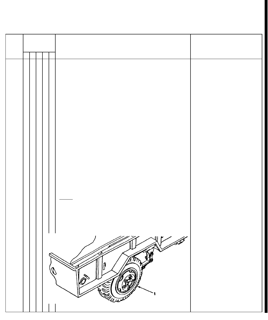
B - Before A - After M - Monthly
D - During W - Weekly
Item Interval
Item to be Inspected
Procedure: Check for and have
repaired, filled, or adjusted
Equipment is not
ready/available
No. BDAWMas needed if:
TM 5-6115-365-15
Table 2-2. Operator/Crew Preventive Maintenance Checks and Services (cont.)
NOTE:
These checks are to be made in the order listed, within designated interval.
8•a. VOLTMETER. Models MEP-016A and Desired voltage can-
cont. MEP-021A adjust for desired voltage. Rotate not be obtained and
voltage selector switch to monitor the various maintained.
output voltage combinations.
Model MEP-026A
Adjust for proper DC volts (must not exceed 28
V max).
•b. FREQUENCY METER. Normal indica- MEP-021A 392-
tion MEP-016A 59-61 408. Indicates fre-
quency too high or
too low.
•c. LOAD METER. Indicates percentage of No indication when
applied load. Rotate current selector switch to load is applied.
monitor the load applied to each phase. Not to
exceed 100%.
•d. TACHOMETER. ENNormal indication RPM is not in the
Models MEP-016A & MEP-021 A. normal operating
range.
MEP-016A 3564-3636 RPM
MEP-021A 3394-3463 RPM
9TIRES
•Check tires (1) for cuts, foreign objects, or One tire (1) is flat,
unusual tread wear. Remove any stones from missing, or unser-
between the treads. Check that tire pressure is viceable.
35 PSI (241.22 kPa) when tires are cool.
Change 10 2-2.3
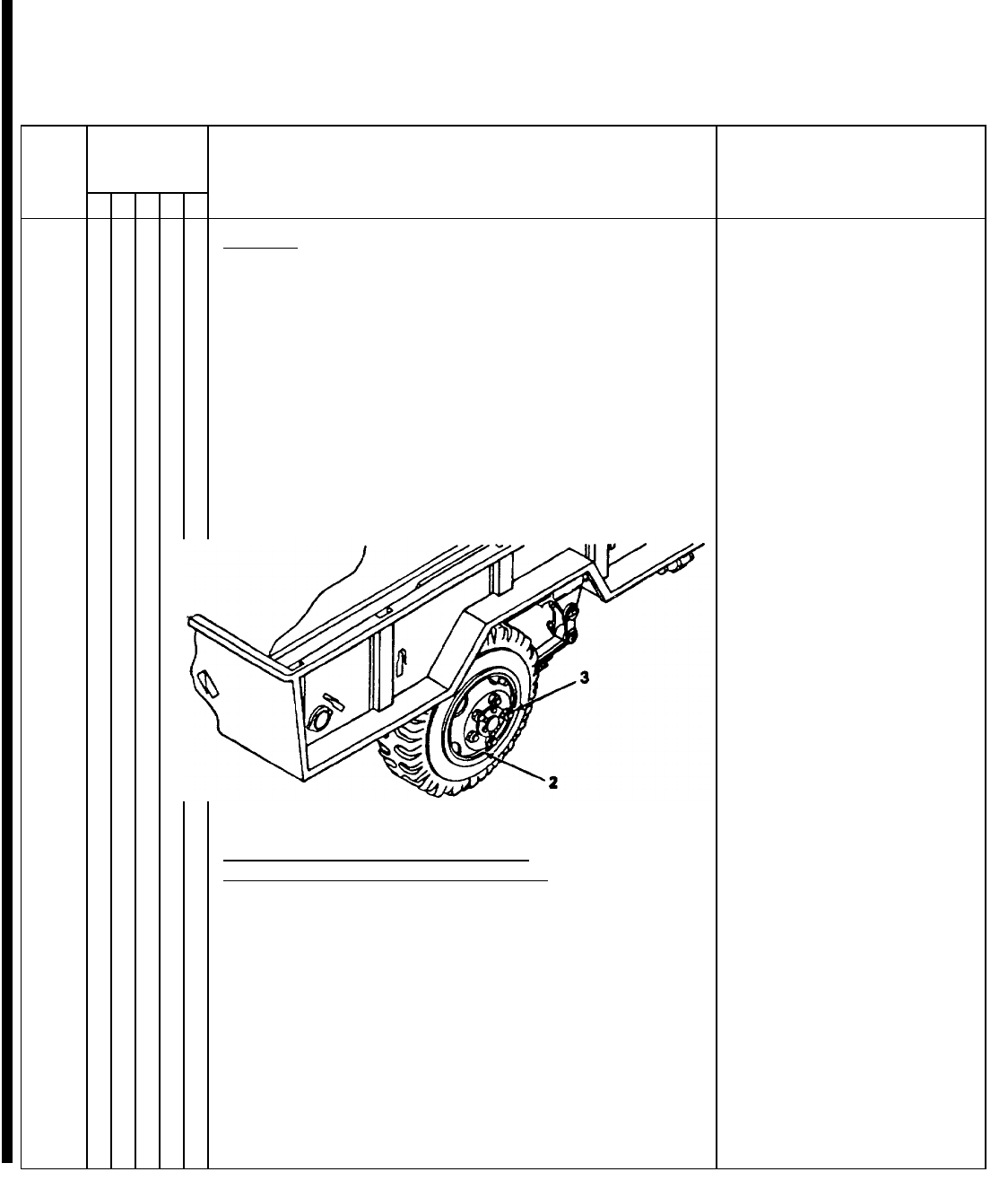
B - Before A - After M - Monthly
D - During W - Weekly
Item Interval
Item to be Inspected
Procedure: Check for and have
repaired, filled, or adjusted
Equipment is not
ready/available
No. BDAWMas needed if:
TM 5-6115-365-15
Table 2-2. Operator/Crew Preventive Maintenance Checks and Services (cont.)
NOTE:
These checks are to be made in the order listed, within designated interval.
10 WHEELS NOTE
On Models M101, M101A1, M116, and M116A1, the left
wheel and stud nuts are turned counterclockwise to
tighten and clockwise to loosen. Right wheel and stud
nuts are turned clockwise to tighten and
counterclockwise to loosen. On Models M101A2 and
M116A2 the left and right stud nuts are turned clockwise
to tighten and counterclockwise to loosen.
•Check wheels (2) for damage and wheel stud One wheel (2) is
nuts (3) for tightness and presence. damaged. One
wheel stud nut (3)
loose or missing.
11 DRAWBAR RING, INTERVEHICULAR
CABLE, SAFETY CHAINS, AND FRAME
•a. Check drawbar ring (4) for secure mounting Ring is loose or
and obvious damage. bent.
•b. Check intervehicular cable (5) for cuts and Intervehicular cable
breaks. is broken or miss-
ing.
2-2.4 Change 10
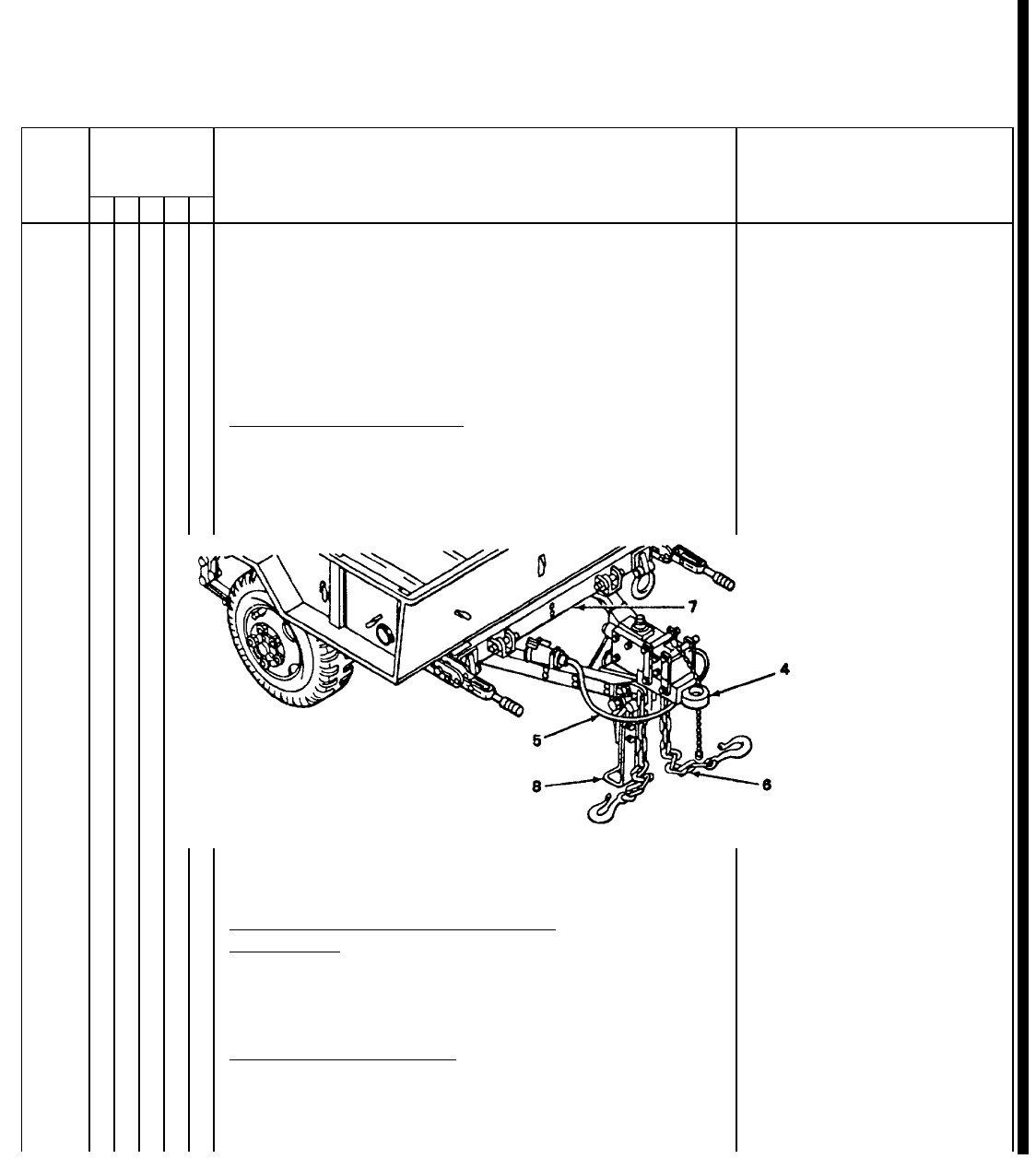
B - Before A - After M - Monthly
D - During W - Weekly
Item Interval
Item to be Inspected
Procedure: Check for and have
repaired, filled, or adjusted
Equipment is not
ready/available
No. BDAWMas needed if:
TM 5-6115-365-15
Table 2-2. Operator/Crew Preventive Maintenance Checks and Services (cont.)
NOTE
These checks are to be made in the order listed, within designated interval.
11 •c. Check safety chains (6) for secure mounting Safety chains are
cont. and obvious damage. missing or unse-
cured.
•d. Inspect the entire chassis frame (7) when Frame is obviously
trailer is loaded for damage, cracks, broken broken or cracked.
welds.
12 SUPPORT LEG ASSEMBLY
•With trailer connected to towing vehicle, check Support leg assem-
support leg assembly (8) for ease of operation. bly is seized.
13 BRAKE SYSTEM - Models M101A2 and
M116A2 only.
•Test brake system by hooking trailer to towing Service brakes fail
vehicle. to operate.
14 •HANDBRAKES - All models
With trailer hooked to towing vehicle, set the Handbrakes cannot
handbrakes (9). Move the trailer slightly to see be adjusted.
if the handbrakes hold the wheels.
Change 10 2-2.5
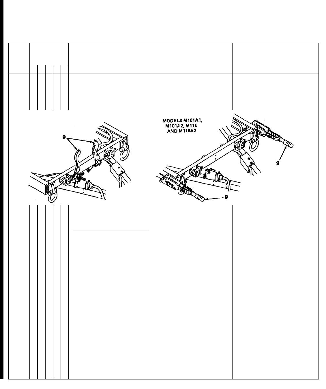
B - Before A - After M - Monthly
D - During W - Weekly
Item Interval
Item to be Inspected
Procedure: Check for and have
repaired, filled, or adjusted
Equipment is not
ready/available
No. BDAWMas needed if:
TM 5-6115-365-15
Table 2-2. Operator/Crew Preventive Maintenance Checks and Services (cont.)
NOTE
These checks are to be made in the order listed, within designated interval.
15 LIGHTS AND REFLECTORS
NOTE
An assistant is required while checking the
brake lights.
•a. Connect the intervehicular cable (10) to the
towing vehicle.
•b. Operate the vehicle light switch through all Lights or reflectors
settings and check the lights (11). Check for are damaged, miss-
damage and presence of reflectors (12). ing, or fail to oper-
ate properly.
2-2.6 Change 10
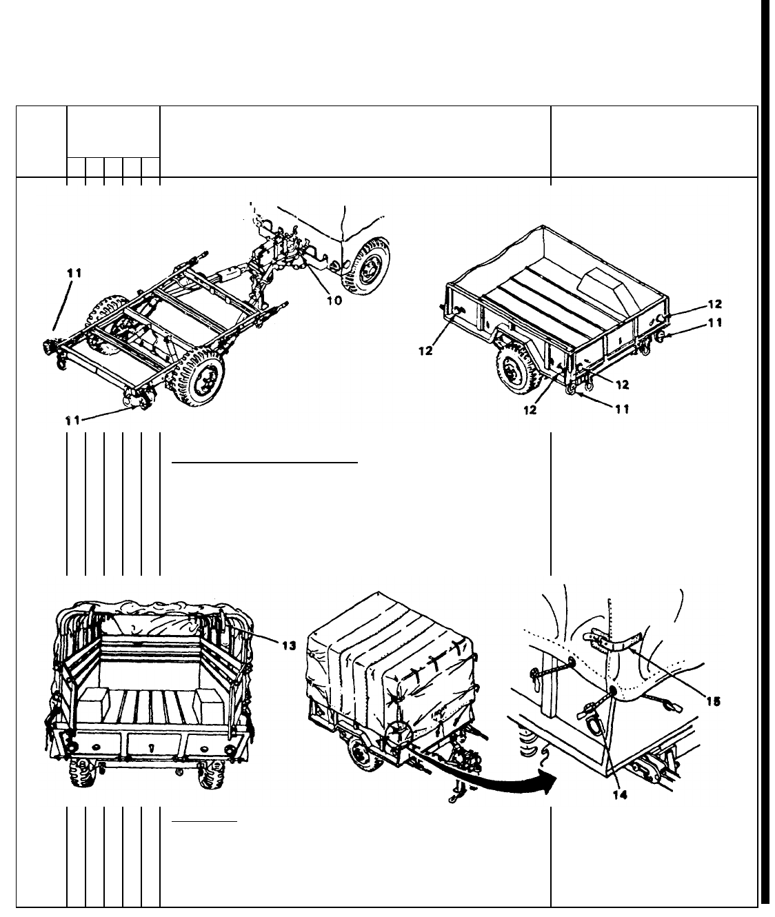
B - Before A - After M - Monthly
D - During W - Weekly
Item Interval
Item to be Inspected
Procedure: Check for and have
repaired, filled, or adjusted
Equipment is not
ready/available
No. BDAWMas needed if:
TM 5-6115-365-15
Table 2-2. Operator/Crew Preventive Maintenance Checks and Services (cont.)
NOTE
These checks are to be made in the order listed, within designated interval.
16 •CANVAS COVER ASSEMBLY
a. Check for missing and bad tiedown straps
and snap fasteners (13).
b. Check for missing and bad ropes (14).
c. Check for missing and bad straps and buck-
les (15).
d. Check for ripped seams and tears.
17 •TAILGATE
a. Check for bad slats (16).
b. Check for missing or bad strap hinge assem-
blies (I 7).
c. Check for missing or bad strap latch assem-
blies (18).
Change 10 2-2.7
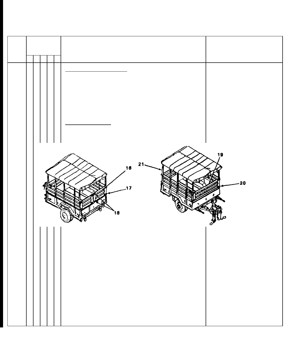
B - Before A - After M - Monthly
D - During W - Weekly
Item Interval
Item to be Inspected
Procedure: Check for and have
repaired, filled, or adjusted
Equipment is not
ready/available
No. BDAWMas needed if:
TM 5-6115-365-15
Table 2-2. Operator/Crew Preventive Maintenance Checks and Services (cont.)
NOTE
These checks are to be made in the order listed, within designated interval.
18 •FRONT RACK ASSEMBLY
a. Check for bad slats (19).
b. Check for missing or bad strap hinge assem-
blies (20).
19 •BOW ASSEMBLIES
Inspect for bad bow assemblies (21).
20 •SIDE RACK ASSEMBLIES
a. Check for missing or bad storage clips (22).
b. Check for bad stakes (23).
c. Check for bad slats (24).
d. Check for missing or bad strap hinge assem-
blies (25).
2-2.8 Change 10
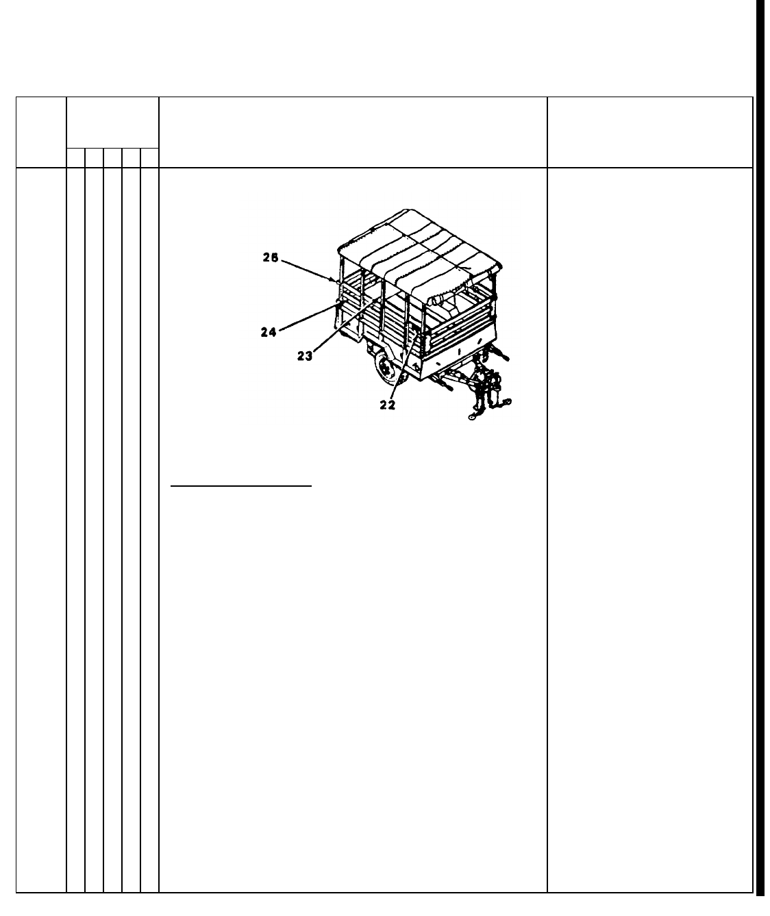
B - Before A - After M - Monthly
D - During W - Weekly
Item Interval
Item to be Inspected
Procedure: Check for and have
repaired, filled, or adjusted
Equipment is not
ready/available
No. BDAWMas needed if:
TM 5-6115-365-15
Table 2-2. Operator/Crew Preventive Maintenance Checks and Services (cont.)
NOTE
These checks are to be made in the order listed, within designated interval.
21 TRAILER OPERATION
•a. Be alert for any unusual noises while towing
the trailer. Stop and investigate any unusual
noises.
•b. Ensure that the trailer is tracking/following Trailer is not track-
correctly behind towing vehicle with no side ing/following cor-
pull. rectly.
Change 10 2-2.9
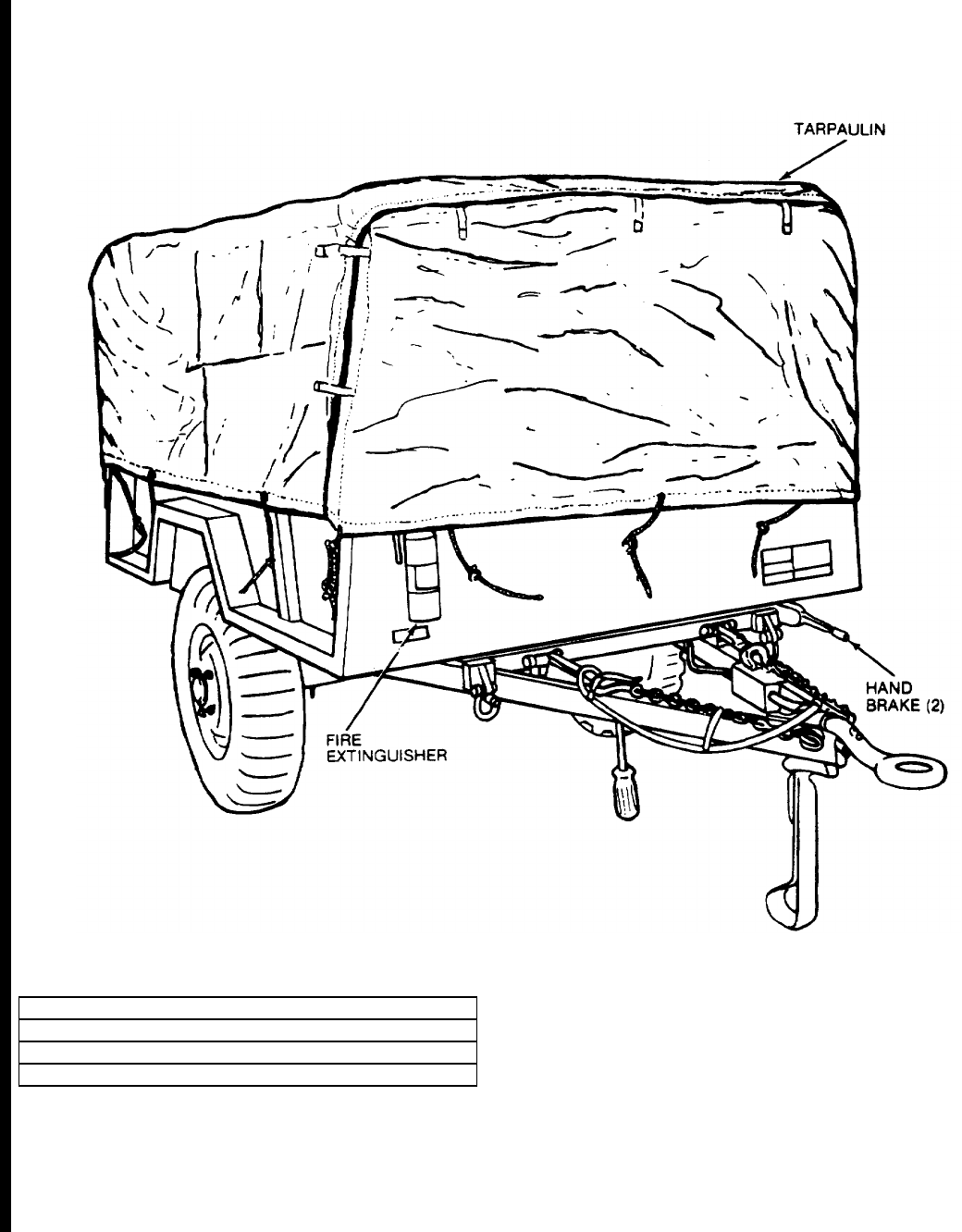
TM 5-6115-365-15
CAUTION
REMOVE TARPAULIN, BOWS AND RACKS BEFORE OPERATION BE SURE
TAILGATE IS DOWN AND REMOVE ANYTHING IN THE TRAILER THAT MIGHT
OBSTRUCT THE FREE CIRCULATION OF AIR.
SHIPPING DIMENSIONS
LENGTH 147 INCHES
WIDTH 74 INCHES
HEIGHT 65 INCHES
WEIGHT 2,175 POUNDS
Figure 2-1. PU-617/M, right front 3/4 view.
2-2.10 Change 10

TM 5-6115-365-15
Section II. OPERATING INSTRUCTIONS
2-3. Setting-Up Instructions
a. Leveling.
(1) Locate the trailer on as level a surface as
possible in order for the generator sets to operate
efficiently.
(2) Set brakes and block wheels securely to
prevent any movement. Operate handbrake at weekly
intervals to assure freedom of linkage.
(3) Pull the leg support down and adjust
length for firm contact with ground.
Warning
Wheels must be blocked, brakes set,
and leg support down in support
position before attempting to roll up
the tarpaulin and before starting to
assemble or set-up the equipment for
operation.
b. Grounding.
Warning
Never operate the generator set until
it has been properly grounded.
Electrical defects in the load lines or
equipment can cause death by
electrocution when contact is made
with an ungrounded system.
(1) The generator set must be grounded prior
to operation. The ground may be any of three methods,
depending on the location and terrain.
(a) The ground rod driven to a depth of
8 feet.
(b) An underground metallic water
piping system.
(c) A metal plate (9 sq ft) buried at a
depth of 4 feet.
(2) The ground lead must be No. 6 AWG
copper wire bolted or clamped to the rod, plate, or piping
system.
(3) Connect the other end of the ground lead
to the generator set ground stud as shown in figure 2-2.
(4) Be sure that both generators are
connected to the generator set ground stud as shown in
figure 2-2.
c. Preparation for Starting.
(1) Remove the canvas tarpaulin and remove
the racks.
(2) Open the trailer tailgate and remove all
loose auxiliary items and anything else that might block
the free circulation of air through the trailer and around
the generator sets.
Caution
It is of foremost importance that
there be free circulation of air around
the generator sets at all times during
operation. Inadequate ventilation is a
major cause of damage to the
equipment.
(3) Be sure the transfer switch load cables
are connected to the generator sets as illustrated in
figure 2-3.
(4) Connect the fuel hoses as illustrated in
figure 2-4.
Warning
Never operate the generator set in an
enclosed area unless the exhaust
gases are piped to the outside.
Inhalation of exhaust fumes will
result in serious illness or death.
2-4. Starting
a. Perform setting-up and pre-starting procedures
(para 2-3).
b. Be sure generator transfer switch is OFF
(fig. 2-3).
c. Start the generator set as instructed in
TM 5-6115-271-14.
2-5. Stopping
a. Turn generator transfer switch OFF or in position
to select standby generator (fig. 2-3).
b. Stop the generator set as instructed in
TM 5-6115-271-14.
2-6. Operation
a. Start the generator (para 2-4) and position
transfer switch to desired generator.
b. Operate the generator as instructed in
TM 5-6115-271-14.
c. Perform the fuel transfer procedure as instructed
in figure 2-4.
Change 8 2-3
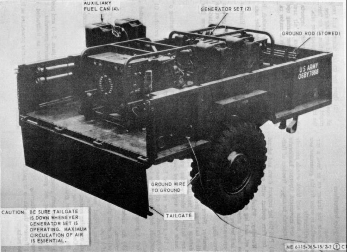
TM 5-6115-365-15
Figure 2-2. PU-617/M set up for operation.
2-4
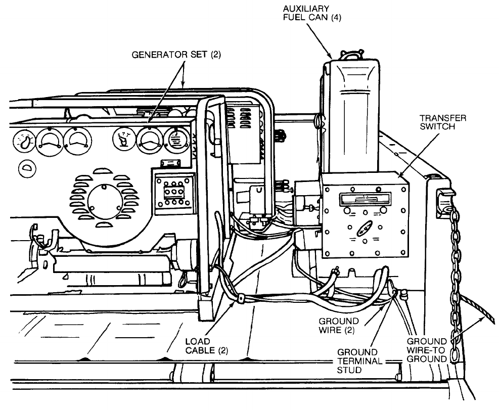
TM 5-6115-365-15
Figure 2-2. Continued.
Change 8 2-5
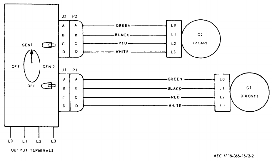
TM 5-6115-365-15
Figure 2-3. Interconnection diagram, transfer switch-to-generators.
2-6
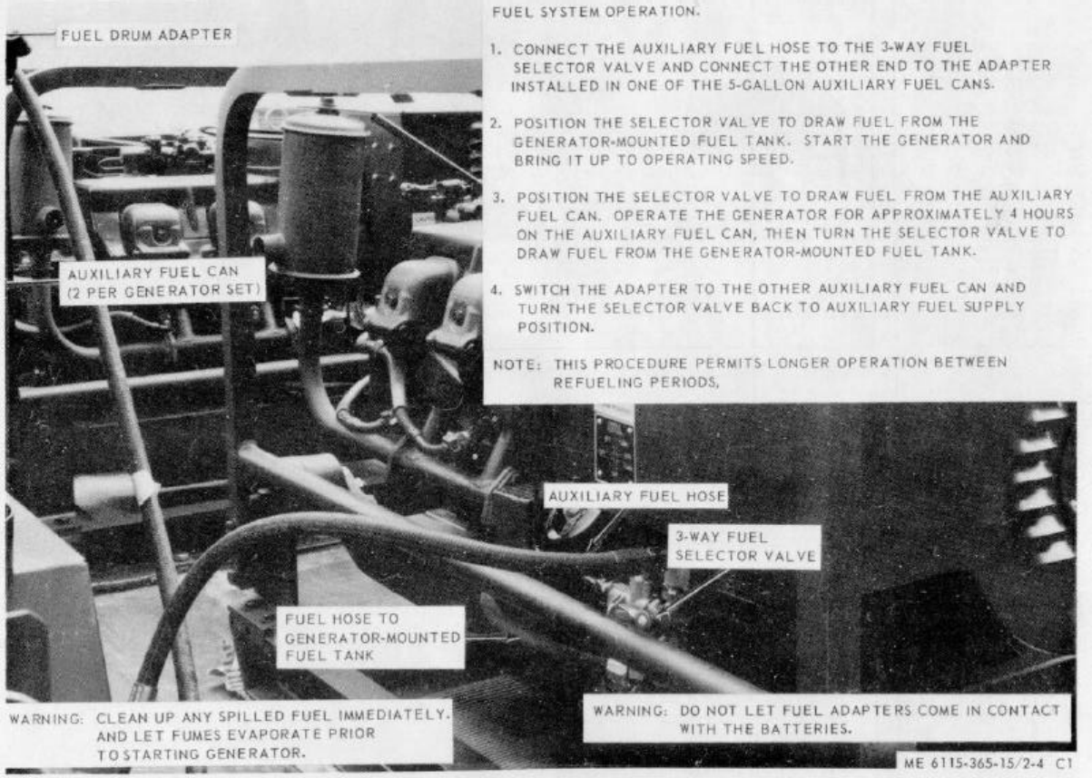
TM 5-6115-365-15
C1
Figure 2-4. Fuel system connection and transfer procedure.
2-7

TM 5-6115-365-15
C1
Section III. OPERATOR'S MAINTENANCE INSTRUCTIONS
2-7. Transfer Switch Indicating Lamps
a. Removal. Remove the indicating lamps as
illustrated in figure 2-5.
b.Installation. Install the indicator light lamps as
illustrated in figure 2-5.
2-8. Field Expedient Repairs
Trouble Probable cause Remedy
Power transfer switch Switch or terminal Disconnect generator sets
will not supply power board defective. from transfer cables and
to load. connect load cables di-
rectly to the individual
terminal boards of the
generator sets.
2-8
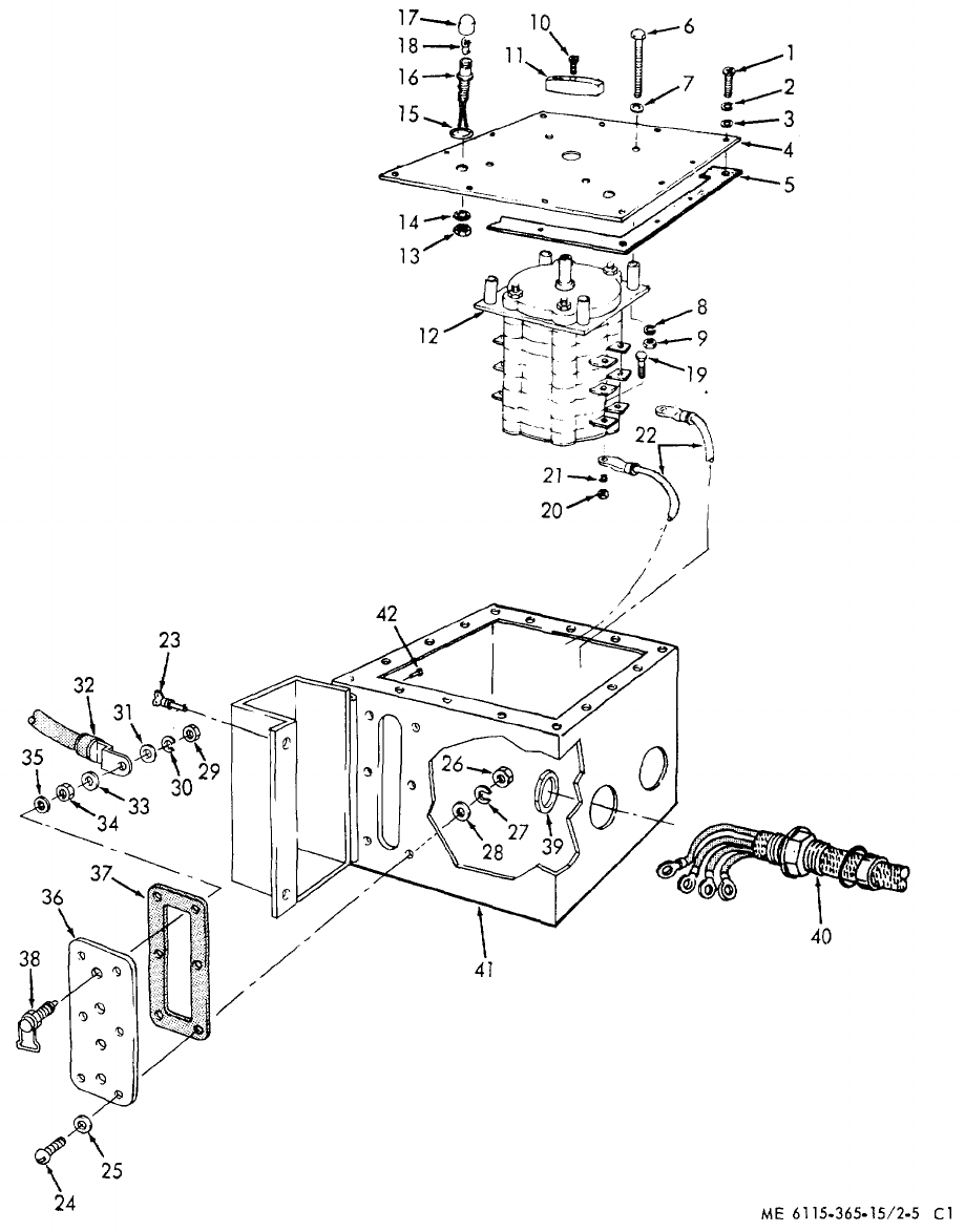
TM 5-6115-365-15
C1
Figure 2-5. Transfer switch, removal, disassembly, reassembly, and installation.
2-10

TM 5-6115-365-15
C1
1Screw 15 Preformed packing 29 Hexnut
2Lockwasher 16 Light and wire assembly 30 Lockwasher
3Flat washer 17 Lens 31 Flatwasher
4Cover 18 Lamp 32 Electrical lead
SGasket 19 Screw 33 Flat washer
6Screw 20 Hexnut 34 Hex nut
7Flat washer 21 Lockwasher 35 Lockwasher
8Lockwasher 22 Electrical lead 36 Terminal board
9Hexnut 23 Fastener 37 Gasket
10 Screw 24 Screw 38 Terminal lug
11 Knob 25 Flat washer 39 Locknut
12 Transfer switch 26 Hex nut 40 Stuffing tube assembly
13 Hex nut 27 Lockwasher 41 Transfer switch box
14 Lockwasher 28 Flat washer 42 Rivet
Figure 2-5. Continued.
Section IV. ORGANIZATIONAL MAINTENANCE INSTRUCTIONS
2-9. Transfer Switch Indicating Lights
a. Removal. Remove the indicating lights as
illustrated in figure 2-5.
b. Installation. Install the indicator or lights as
illustrated in figure 2-5.
2-10. Ground Wires and Terminal Stud
a. Removal. Remove the ground wires from the
ground terminal and generator sets as shown in figure
2-2. Remove the terminal stud.
b. Installation. Install the ground wires, and
terminal stud as shown in figure 2-2.
Section V. DIRECT AND GENERAL SUPPORT AND DEPOT
MAINTENANCE INSTRUCTIONS
2-11. Generator Transfer Switch
a. Removal and Disassembly.
(1) Tag and disconnect leads from the output
terminals to load.
(2) Remove and disassemble the transfer
switch as illustrated in figure 2-5.
b. Reassembly and Installation.
(1) Reassemble and install the transfer switch
as illustrated in figure 2-5.
(2) Connect load connections. (Refer to fig. 2-6).
2-12. Generator Sets
a. Removal. Using figure 2-7 as a guide, perform
the following steps:
(1) Disconnect fuel lines.
(2) Disconnect electrical leads and cables.
(3) Disconnect oil drain adapters.
(4) Remove 8 bolts that secure the two
generator sets to the trailer and remove the generator
sets.
b. Installation. Using figure 2-7 as a guide, perform
the following steps:
(1) Secure the two generator sets to the
trailer bed with 8 bolts.
(2) Connect the oil drain adapters.
(3) Connect the electrical leads and cables.
(4)Connect fuel lines.
2-11
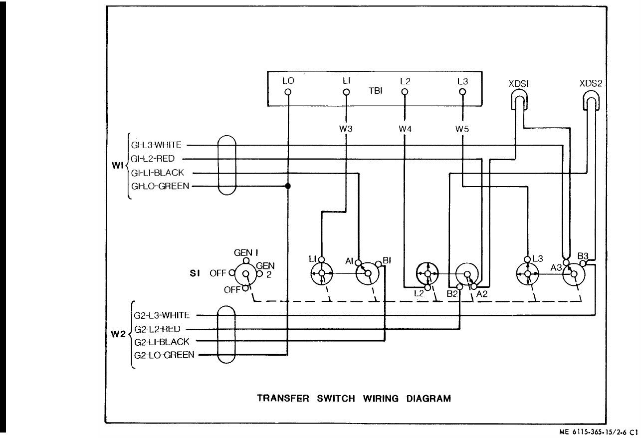
TM 5-6115-365-15
Figure 2-6. Transfer switch wiring diagram.
2-12 Change 8
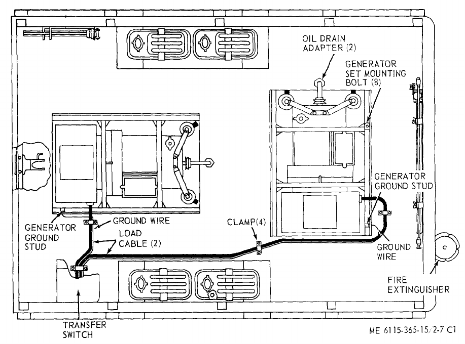
TM 5-6115-365-15
C1
Figure 2-7. PU-617M overall component location diagram.
2-13
(1) (2) (3) (4) (5) (6) (7)
FEDERAL DESCRIPTION UNIT QTY 15-DAY ORGANIZATIONAL ILLUS-
SMR STOCK OF INC MAINTENANCE ALW RATION
CODE NUMBER USABLE MEAS IN (a) (b) (c) (d) (a) (b)
ON UNIT FIG ITEM
REF NUMBER & MFG CODE CODE 1-5 6-20 21-50 51-100 NO. NO.
TM 5-6115-365-15
C 1
PART I
REPAIR PARTS FOR ORGANIZATIONAL MAINTENANCE
00001 GROUP 01 - ENGINE
00002 0106 - ENGINE LUBRICATION SYSTEM
04730-270-4581 ADAPTER: 1/2-20 x 1/4-18 EA 2****
00003
P04730-908-3194 CLAMP EA 4****
00004 MS35842-11 (96906)
04820-277-1765 COCK, PLUG, SPRING, KEY: 1/4-18 x 1/4-18 EA 2****
00005
04730-278-6317 COUPLING: 1/4, iron pipe size EA 2****
00006
M0HOSE: 1/2-10 x 10 in. lg, oil drain EA 2
00007 SAEJ30CL30RSTYPE1 (81348)
MANUFACTURE FROM :
P04730-684-6032 HOSE: 1/2-10 oil drain (As required) FT SEE GRP 9501
00008 SAEJ30CL30RS (81348)
05310-584-5272 LOCK, WASHER: 1/2 IN. EA 2****
00009
04730-196-1465 NIPPLE, CLOSE: 1/4 iron pipe size x 7/8, lg EA 2****
00010
04730-196-1502 NIPPLE: 1/4, iron pipe size, x 1-1/2, lg EA 2****
00011
05310-282-7818 NUT: 1/2 IN. EA 2****
00012
05330-684-3430 “O" RING EA 2****
00013
04730-277-6447 UNION, BULK HEAD EA 2****
00014
00015 GROUP 15 - FRAME, TOWING, ATTACHMENTS, AND DRAWBARS
00016 1501 - FRAME ASSEMBLY
X2 02590-473-6331 BRACKET ASSEMBLY: liquid count, 5 gal EA 4
00017 MS53052-1 (96906)
X2 0BRACKET ASSEMBLY, SLEDGE HAMMER EA 1
00018 13214E1214 (97403)
X2 0CLAMP EA 3
00019 13212E3573 (97403)
X2 0CLAMP EA 1
00020 13212E3572 (97403)
X2 0CLAMP, GROUND ROD EA 4
00021 13212E3617-1 (97403)
X2 0CLIP SPRING, SLEDGE HAMMER EA 1
00022 13214E1213-1 (97403)
X2 0HOLDER, FUEL ADAPTER EA 4
00023 13211E4889-2 (97403)
X2 0HOLDER, FUEL DRUM ADAPTER EA 2
00024 13212E3553-1 (97403)
X2 0HOLDER, SPOUT CAN, FLEXIBLE EA 2
00025 13212E3553-2 (97403)
X2 0NUT, PLAIN, HEXAGON: No. 4-40 machine, screw EA 8
00026 MS35649-242 (96906)
X2 0NUT, SELF-LOCKING, HEXAGON: 1/4-20 EA 6
00027 MS51922-1 (96906)
X2 0NUT, SELF-LOCKING, HEXAGON: 1/4-20 EA 1
00028 MS51922-1 (96906)
X2 0NUT, SELF-LOCKING, HEXAGON: 1/4-20 EA 2
00029 MS51922-1 (96906)
2-14

(1) (2) (3) (4) (5) (6) (7)
FEDERAL DESCRIPTION UNIT QTY 15-DAY ORGANIZATIONAL ILLUS-
SMR STOCK OF INC MAINTENANCE ALW RATION
CODE NUMBER USABLE MEAS IN (a) (b) (c) (d) (a) (b)
ON UNIT FIG ITEM
REF NUMBER & MFG CODE CODE 1-5 6-20 21-50 51-100 NO. NO.
TM 5-6115-365-15
C 1
X2 0NUT, SELF-LOCKING, HEXAGON: 1/4 x 20 EA 4
00030 MS51922-1 (96906)
X2 0NUT, SELF-LOCKING, HEXAGON: 1/4-20 EA 8
00031 MS51922-1 (96906)
X2 0NUT, SELF-LOCKING, HEXAGON: 3/8-16 EA 16
00032 MS51922-17 (96906S
X2 0NUT, SELF-LOCKING, HEXAGON: 5/16-18 EA 4
00033 MS51922-9 (96906)
X2 0NUT, SELF-LOCKING, HEAD: 5/16-18 EA 4
00034 MS51922-9 (96906)
X2 0SCREW, CAP, HEXAGON HEAD: 1/4-20 x 1, lg EA 2
00035 MS90725-8 (96906)
X2 0SCREW, CAP, HEXAGON HEAD EA 6
00036 MS90725-8 (96906)
X2 0SCREW, CAP, HEXAGON HEAD: 1/4-20 x 3/4, lg EA 1
00037 MS90725-6 (96906)
X2 0SCREW, CAP, HEXAGON HEAD: 1/4-20 x 3/4, lg EA 2
00038 MS90725-6 (96906)
X2 0SCREW, CAP, HEXAGON HEAD: 3/8-16 x 1-1/4 EA 16
00039 MS90725-62 (96906)
X2 0SCREW, CAP, HEXAGON HEAD: 5/16-18 x 1, lg EA 4
00040 MS90725-34 (96906)
X2 0SCREW, CAP, HEXAGON HEAD: 5/16-18 x 1, lg EA 4
00041 MS90725-34 (96906)
X2 0SCREW, MACHINE: flat head, 1/4-20 x 3/4, lg EA 8
00042 MS35190-289 (96906)
X2 0SCREW, MACH , PAN HEAD: 4-40 x 5/8, lg EA 8
00043 MS35206-218 (96906)
X2 0WASHER, FLAT: round, 3/8 screw size EA 32
00044 MS27183-14 (96906)
X2 0WASHER, FLAT: round, 1/4, nominal size EA 8
00045 MS27183-10 (96906)
X2 0WASHER, FLAT: round, 1/4 nominal size EA 2
00046 MS27183-10 (96906)
X2 0WASHER, FLAT.: round, 1/4 nominal, size EA 4
00047 M27183-10 (96906)
X2 0WASHER, FLAT: round, 1/4 screw size EA 12
00048 MS27183-10 (96906)
X2 0WASHER, FLAT: round, 1/4-20 screw size EA 4
00049 MS27183-10 (96906)
X2 0WASHER, FLAT: round, 4-10 screw size EA 16
00050 MS27183-3 (96906)
X2 0WASHER, FLAT: round, 5/16 EA 8
00051 MS27183-12 (96906)
X2 0WASHER, FIAT: round, 5/16 screw size EA
00052 MS27183-12 (96906)
X2 0WASHER, LOCK, SPLIT, HELICAL EA 8
00053 MS35338-40 (96906)
00054 1507 - LANDING GEAR, LEVELING JACKS
(MECHANICAL OR HYDRAULIC)
P02590-318-6691 TRAILER LEG, PROP ASSEMBLY EA 1****
00055 13214E1206 (97403)
X2 0BRACKET, TRAILER PROP ASSEMBLY EA 1
00056 13214E1207 (97403)
2-15
(1) (2) (3) (4) (5) (6) (7)
FEDERAL DESCRIPTION UNIT QTY 15-DAY ORGANIZATIONAL ILLUS-
SMR STOCK OF INC MAINTENANCE ALW RATION
CODE NUMBER USABLE MEAS IN (a) (b) (c) (d) (a) (b)
ON UNIT FIG ITEM
REF NUMBER & MFG CODE CODE 1-5 6-20 21-50 51-100 NO. NO.
TM 5-6115-365-15
C 1
X2 0FITTING, LUBRICATION: 1/8-27 thd EA 1
00057 MS15006-1 (96906)
X2 0LEG, BASE EA 1
00058 13214E1212 (97403)
X2 0LEG, UPPER EA 1
00059 13214E1208 (97403)
X2 0NUT EA 1
00060 13214E1211 (97403)
X2 0NUT, SELF-LOCKING HEXAGON: 3/8-16 EA 3
00061 MS51922-17 (96906)
X2 0PIN, COTTER: 1/8 dia, x 3/4, lg EA 1
00062 MS24665-351 (96906)
X2 0RIVET, SOLID: universal head, 1/4 x 2, lg EA 1
00063 MS20613-8P32 (96906)
X2 0SCREW EA 1
00064 13214E1210 (97403)
X2 0SCREW, CAP, HEXAGON HEAD: 3/8-16 x 1-1/4 EA 3
00065 MS90725-62 (96906)
X2 0SHAFT EA 1
00066 13214E1209 (97403)
X2 0WASHER, FLAT: round, 3/8 nominal size EA 6
00067 MS27183-14 (96906)
00068 GROUP 22 - BODY CHASSIS OR BULL, AND ACCESSORY ITEMS
00069 2202 - ACCESSORY ITEMS
PC2910-066-1235 ADAPTER ASSEMBLY, FUEL DRUM EA 2****
00070 13211E7541 (97403)
P07240-222-3088 CAN, GASOLINE: 5 gallon, Military EA 4****
00071 MILG1283 (81349)
PC5120-203-4656 HAMMER HAND: double face, 8 lb EA 1****
00072 GGGH86TYPEXCLASS1 (81348)
X2 0NUT, PLAIN, HEXAGON: brass, 3/8-16 EA 1
00073 MS16203-27 (96906)
PC5975-878-3791 ROD, GROUND: w/attachments EA 2****
00074 MILR11461TYPE2STYLE2 (81349)
X2 0SCREW, CAP, HEXAGON HEAD: 3/8-16 x 3/4, lg EA 1
00075 MS35309-358 (96906)
X2 0SPOUT CAN: flexible, w/adapter assembly EA 2
00076 MILS1285 (81349)
X2 0TERMINAL, LUG, CRIMP: No. 6 3/8, stud EA 3
00077 MS20659-110 (96906)
X2 0WASHER, FLAT, BRASS, ELECTRIC: 3/8 thd size EA 2
00078 AN961-66T (88044)
00079 2210 - DATA PLATES AND INSTRUCTION HOLDERS
X2 0PLATE, IDENTIFICATION: ground term EA 1
00080 13205E4918 (97403)
X2 0PLATE, IDENTIFICATION EA 1
00081 13205E4916-1 (97403)
00082 GROUP 40 - ELECTRICAL MOTOR AND GENERATORS
00083 4000 - GENERATOR ASSEMBLY
X2 0NUT, SELF-LOCKING, HEXAGON:1/2-13 UNC EA 8
00084 MS51922-33 (96906)
X2 0SCREW, CAP, HEXAGON HELD: 1/2-13 x 1-3/4 EA 8
00085 MS90725-114 (96906)
2-16
(1) (2) (3) (4) (5) (6) (7)
FEDERAL DESCRIPTION UNIT QTY
15-DAY ORGANIZATIONAL
ILLUS-
SMR STOCK OF INC MAINTENANCE ALW RATION
CODE NUMBER USABLE MEAS IN (a) (b) (c) (d) (a) (b)
ON UNIT FIG
ITEM
REF NUMBER & MFG CODE CODE 1-5 6-20
21-50
51-100
NO. NO.
TM 5-6115-365-15
PAOZZ 5365-00-915-8370 SPACER EA 8
00086 13212E3554 (97403)
X2 OWASHER, BEVELED EA 8
00087 13206E4482-2 (97403)
X2 OWASHER, FLAT: round, 1/2 screw size EA 8
00088 MS27183-18 (96906)
00089 4019 - RADIO INTERFERENCE SUPPRESSION
MOLEAD, GROUND: generator No. 1 to stud, 10 ft EA 1
00090 MANUFACTURE FROM:
POWIRE, ELECTRICAL: copper No. 6 FT SEE GRP 9501
00091 QQW343TYPERBCLASS1 (81349)
MOLEAD, GROUND: generator No. 2 to stud, 4 ft EA 1
00092 MANUFACTURE FROM:
POWIRE, ELECTRICAL: No. 6 FT SEE GRP 9501
00093 QQW343TYPERBCLASS1 (81349)
X2 ONUT, PLAIN, HEXAGON: 3/8-16 EA 2
00094 MS16203-39 (96906)
X2 ONUT, PLAIN, HEXAGON: brass, 3/8-16 EA 1
00095 MS16203-27 (96906)
X2 ONUT, PLAIN, WING: brass, 3/8-16 EA 1
00096 MS35425-28 (96906)
X2 OSTUD EA 1
00097 13214E1223 (97403)
X2 OWASHER, FLAT, ELECTRIC: 3/8 in thd size EA 4
00098 AN961-66T (88044)
X2 OWASHER, LOCK: flat external tooth, 3/8 EA 2
00099 MS35335-91 (96906)
00100 GROUP 42 - ELECTRICAL EQUIPMENT
00101 4206 - THERMOSTATIC, AUTOMATIC AND MANUAL
CONTROL DEVICES
X2 ONUT, SELF-LOCKING, HEXAGON: 3/8-16 EA 4
00102 MS51922-17 (96906)
X2 OPLATE EA 1
00103 13212E3569 (97403)
X2 OSCREW, CAP, HEXAGON HEAD: 3/8-16 x 1-1/4 EA 4
00104 MS90725-62 (96906)
X2 OWASHER, FLAT: round, 3/8 screw EA 8
00105 MS27183-14 (96906)
00106 GROUP 76 - FIRE FIGHTING EQUIPMENT COMPONENTS
00107 7638 - PORTABLE FIRE FIGHTING EQUIPMENT
PC4210-555-8837 EXTINGUISHER, FIRE W/BRACKET EA 1****
00108 MILE52031 (81349)
X2 ONUT, SELF-LOCKING, HEXAGON: 1/4-20 EA 4
00109 MS51922-1 (96906)
X2 OSCREW, CAP, HEXAGON HEAD: 1/4-20 x 1, Ig EA 4
00110 MS90725-8 (96906)
X2 OWASHER EA 8
00111 MS27183-10 (96906)
00112 GROUP 95 - GENERAL USE STANDARDIZED PARTS
00113 9501 - HARDWARE SUPPLIES AND BULK MATERIAL,
COMMON
PO4730-684-6032 HOSE, 1 2 id FT ****
00114 SAEJ30CL30RSTYPE1 (81348)
Change 8 2-17
(1) (2) (3) (4) (5) (6) (7)
FEDERAL DESCRIPTION UNIT QTY
15-DAY ORGANIZATIONAL
ILLUS-
SMR STOCK OF INC MAINTENANCE ALW RATION
CODE NUMBER USABLE MEAS IN (a) (b) (c) (d) (a) (b)
ON UNIT FIG
ITEM
REF NUMBER & MFG CODE CODE 1-5 6-20
21-50
51-100
NO. NO.
TM 5-6115-365-15
C1
POWIRE, ELECTRICAL: copper, No. 6 uninsulated FT ****
00115 QQW343TYPERBCLASS1 (81349)
2-18 Change 1
(1) (2) (3) (4) (5) (6) (7) (8) (9) (10)
DESCRIPTION 1-YR
DEPOT
QTY 30-DAY DS MAINT 30-DAY GS MAINT ALW
PER MAINT
ALW ILLUS-
TRATION
FEDERAL USABLE UNIT INC ALLOWANCE ALLOWANCE 100 PER (a) (b)
SMR
CODE STOCK
NUMBER
ON
ref NUMBER & MFR CODE CODE OF
MEAS IN
UNIT (a)
1-20 (b)
21-50 (c)
51-100 (a)
1-20 (b)
21-50 (c)
51-100
EQUIP
CNTGCY 100
EQUIP FIG.
NO. ITEM
NO.
TM 5-6115-365-15
PART II
REPAIR PARTS FOR DS, GS,
AND DEPOT MAINTENANCE
00001 GROUP 01-ENDING
00002 0106 - ENGINE LUBRICATION SYSTEM
O4730-270-4581 ADAPTER: 1/2-20X 1/4-18 EA 2••••••• •
00003
PO4730-908-3196 CLAMP EA 4• • 2• • 2 10 10
00004 MS35842-11(96906)
O4820-277-1765 COCK, PLUG, SPRING, KEY: 1/4-18 X 1/4-18 EA 2••••••• •
00005
O4730-00-187-7595 COUPLING: 1/4, iron pipe size EA 2••••••• •
00006 13218E0064-2
MOHOSE: 1/2-10 X 10 in. 1g, oil drain EA 2
00007 SAEJ30CL30RSTYPE1 (81348)
MANUFACTURE FROM:
PO4730-684-6032 HOSE: 1/2-10, oil drain (As required) FT SEE GRP 9501
00008 SAEJ30CL30RS (81348)
O5310-584-5272 LOCK, WASHER: 1/2 IN. EA 2••••••• •
00009
O4730-196-1465 NIPPLE, CLOSE: 1/4, iron pipe size X 7/8, Ig EA 2••••••• •
00010
O4730-196-1502 NIPPLE, 1/4, iron pipe size, X 1-1/2, lg EA 2••••••• •
00011
O5310-282-7818 NUT: 1/2 IN. EA 2••••••• •
00012
O5330-684-3420 "O" RING EA 2••••••• •
00013
O4730-277-6447 UNION, BULK HEAD EA 2••••••• •
00014
00015 GROUP 15 - FRAME, TOWING
ATTACHMENTS, AND DRAWBARS
00016 1501 - FRAME ASSEMBLY
X2 O2590-473-6331 BRACKET ASSEMBLY: liquid count, 5 gal EA 4
00017 MS53052-1 (96906)
X2 OBRACKET ASSEMBLY, SLEDGE HAMMER EA 1
00018 13214E1214(97403)
X2 OCLAMP EA 3
00019 13212E3573(97403)
X2 OCLAMP EA 1
00020 13212E3572(97403)
X2 OCLAMP, GROUND ROD EA 4
00021 13212E3617-1 (97403)
X2 OCLIP SPRING, SLEDGE HAMMER EA 1
0002 2 13214E1213-1 (97403)
X2 OHOLDER, FUEL ADAPTER EA 4
00023 13211 E4889-2 (97403)
X2 OHOLDER, FUEL DRUM ADAPTER EA 2
00024 1321E3553-1 (97403)
X2 OHOLDER, SPOUT, CAN, FLEXIBLE EA 2
00025 13212E3553-2 (97403)
X2 ONUT, PLAIN, HEXAGON: No. 4-40 machine. EA 8
screw
00026 MS35649-242 (96906)
X2 ONUT, SELF-LOCKING, HEXAGON: 1/4-20 EA 6
00027 MS51922-1 (96906)
X2 ONUT, SELF-LOCKING, HEXAGON: 1/4-20 EA 1
00028 MS51922-1 (96906)
Change 10 2-19

(1) (2) (3) (4) (5) (6) (7) (8) (9) (10)
DESCRIPTION 1-YR
DEPOT
QTY
30-DAY DS MAINT
30-DAY GS MAINT
ALW
PER MAINT
ALW ILLUS-
TRATION
FEDERAL USABLE UNIT INC ALLOWANCE ALLOWANCE 100 PER (a) (b)
SMR
CODE STOCK
NUMBER
ON
ref NUMBER & MFR CODE CODE OF
MEAS
IN
UNIT (a)
1-20 (b)
21-50 (c)
51-100 (a)
1-20 (b)
21-50 (c)
51-100
EQUIP
CNTGCY
100
EQUIP FIG.
NO. ITEM
NO.
TM 5-6115-365-15
C1
X2 ONUT, SELF-LOCKING, HEXAGON: 1/4-20 EA 2
00029 MS51922-1 (96906)
X2 ONUT, SELF-LOCKING, HEXAGON: 1/4-20 EA 4
00030 MS51922-1 (96906)
X2 ONUT, SELF-LOCKING, HEXAGON: 1/4-20 EA 8
00031 MS51922-1 (96906)
X2 ONUT, SELF-LOCKING, HEXAGON: 3/8-16 EA 16
0O032 MS51922-1(96906)
X2 ONUT, SELF-LOCKING, HEXAGON: 5/16-18 EA 4
00033 MS51922-9 (96906)
X2 ONUT, SELF-LOCKING, HEXAGON: 5/16-18 EA 4
00034 MS51922-9 (96906)
X2 OSCREW, CAP, HEXAGON HEAD: 1/4-20 X 1, lg EA 2
00035 MS90725-8 (96906)
X2 OSCREW, CAP, HEXAGON HEAD EA 6
00036 MS90725-8 (96906)
X2 OSCREW, CAP, HEXAGON HEAD: 1/4-20 X 3/4, lg EA 1
00037 MS90725-6 (96906)
X2 OSCREW, CAP, HEXAGON HEAD: 1/4-20 X 3/4, lg EA 2
00038 MS90725-6 (96906)
X2 OSCREW, CAP, HEXAGON HEAD: 3/8-16 X 1-1/4 EA 16
00039 MS90725-62 (96906)
X2 OSCREW, CAP, HEXAGON HEAD: 5/16-18 X 1, lg EA 4
00040 MS90725-34 (96906)
X2 OSCREW, CAP, HEXAGON HEAD: 5/16-18 X 1, lg EA 4
00041 MS90725-34 (96906)
X2 OSCREW, MACHINE: flat head, 1/4-20 X 3/4, lg EA 8
00042 MS35190-289 (96906)
X2 OSCREW, MACHINE, PAN HEAD: 4-40 X 5/8, lg EA 8
00043 MS35206-218 (96906)
X2 OWASHER, FLAT: round, 3/8, screw size EA 32
00044 MS27183-14 (96906)
X2 OWASHER, FLAT: round, 1/4, nominal size EA 8
00045 MS27183-10 (96906)
X2 OWASHER, FLAT: round, 1/4, nominal size EA 2
00046 MS27183-10 (96906)
X2 OWASHER, FLAT: round, 1/4, nominal size EA 4
00047 MS27183-10 (96906)
X2 OWASHER, FLAT: round, 1/4, screw size EA 12
00048 MS27183-10 (96906)
X2 OWASHER, FLAT: round, 1/4-20, screw size EA 4
00049 MS27183-10 (96906)
X2 OWASHER, FLAT: round, 4-10, screw size EA 16
00050 MS27183-3 (96906)
X2 OWASHER, FLAT: round, 5/16 EA 8
00051 MS27183-12 (96906)
X2 OWASHER, FLAT: round, 5/16, screw size EA 8
00052 MS27183-12 (96906)
X2 OWASHER, LOCK, SPLIT, HELICAL EA 8
00053 MS35338-40 (96906)
2-20
(1) (2) (3) (4) (5) (6) (7) (8) (9) (10)
DESCRIPTION 1-YR
DEPOT
QTY
30-DAY DS MAINT
30-DAY GS MAINT
ALW
PER MAINT
ALW ILLUS-
TRATION
FEDERAL USABLE UNIT INC ALLOWANCE ALLOWANCE 100 PER (a) (b)
SMR
CODE STOCK
NUMBER
ON
ref NUMBER & MFR CODE CODE OF
MEAS
IN
UNIT (a)
1-20 (b)
21-50 (c)
51-100 (a)
1-20 (b)
21-50 (c)
51-100
EQUIP
CNTGCY
100
EQUIP FIG.
NO. ITEM
NO.
TM 5-6115-365-15
00054 1507-LANDING GEAR, LEVELING JACKS
(MECHANICAL OR HYDRAULIC)
PO2590-00-420-8929 TRAILER LEG, PROP ASSEMBLY EA 1* * 2* * 2 10 10
00055 13214E1206 (97403)
PB BRACKET, TRAILER PROP ASSEMBLY EA 1
00056 13214E1207 (97403)
X2 OFITTING, LUBRICATION 1/8-27 THD EA 1
00057 MS15006-1 (96906)
X2 OLEG, BASE EA 1
00058 13214E1212 (97403)
X2 OLEG, UPPER EA 1
00059 13214E1208 (97403)
X2 ONUT EA 1
00060 13214E1211 (97403)
X2 ONUT, SELF-LOCKING, HEXAGON 3/8-16 EA 3
00061 MS51922-17 (96906)
X2 OPIN, COTTER: 1/8 DIA, X 314, LG EA 1
00062 MS24665-351 (96906)
X2 ORIVET, SOLID: UNIVERSAL HEAD, EA 1
00063 1/4 x 2, LG
MS20613-8P32 (96906)
X2 OSCREW EA 1
00064 13214E1210 (97403)
X2 OSCREW, CAP, HEXAGON HEAD: 3/8-16 x 1-1/4 EA 3
00065 MS90725-62 (96906)
X2 OSHAFT EA 1
00066 13214E1209 (97403)
X2 OWASHER, FLAT: ROUND, 3/8, NOMINAL SIZE EA 6
00067 MS27183-14 (96906)
00068 GROUP 18-BODY, CAB,
HOOD AND HULL
00069 1810-CARGO BODY
X2 DR TRAILER EA 1
00070 13212E3552 (97403)
00071 GROUP 22-BODY CHASSIS OR HULL,
AND ACCESSORY ITEMS
00072 2202-ACCESSORY ITEMS
PC2910-066-1235 ADAPTER ASSEMBLY, FUEL DRUM EA 2* * 2* * 2 10 10
00073 13211E7541 (97403)
PO7240-222-3088 CAN, GASOLINE: 5 GALLON, MILITARY EA 4* * 2* * 2 10 10
00074 MILG1283 (81349)
PC5120-203-4656 HAMMER HAND: DOUBLE FACE, 8 LB EA 1* * 2* * 2 10 10
00075 GGGH86TYPEXCLASS1 (81348)
X2 ONUT, PLAIN, HEXAGON: BRASS, 3/8-16 EA 1
00076 MS16203-27(96906)
PC5975-878-3791 ROD GROUND: W/ATTACHMENTS EA 2* * 2* * 2 10 10
00077 MILR11461TYPE2STYLE2 (81349)
X2 OSCREW, CAP, HEXAGON HEAD: 3/8-16 x 3/4, LG EA 1
00078 MS35309-358 (96906)
X2 OSPOUT CAN: FLEXIBLE, W/ADAPTER ASSEMBLY EA 2
00079 MILS1285 (81349)
X2 OTERMINAL LUG, CRIMP: NO 6 3/8, STUD EA 3
00080 MS20659-110 (96906)
Change 9 2-21
(1) (2) (3) (4) (5) (6) (7) (8) (9) (10)
DESCRIPTION 1-YR
DEPOT
QTY 30-DAY DS MAINT 30-DAY GS MAINT ALW
PER MAINT
ALW ILLUS-
TRATION
FEDERAL USABLE UNIT INC ALLOWANCE ALLOWANCE 100 PER (a) (b)
SMR
CODE STOCK
NUMBER
ON
ref NUMBER & MFR CODE CODE OF
MEAS IN
UNIT (a)
1-20 (b)
21-50
(c)
51-100
(a)
1-20 (b)
21-50
(c)
51-100
EQUIP
CNTGCY 100
EQUIP FIG.
NO. ITEM
NO.
TM 5-6115-365-15
X2 OWASHER, FLAT, BRASS, ELECTRIC: 3/8 thd EA 2
00081 size
AN961-66T (88044)
00082 2210 - DATA PLATES
AND INSTRUCTION HOLDERS
X2 OPLATE, IDENTIFICATION: ground terminal EA 1
00083 13205E4918 (97403)
X2 OPLATE, IDENTIFICATION EA 1
00084 13205E4916-1 (97403)
X2 FPLATE INFORMATION, WIRING DIAGRAM EA 1
00085 13214E1499 (97403)
00086 GROUP 40 - ELECTRICAL MOTOR
AND GENERATORS
00087 4000 - GENERATOR ASSEMBLY
X2 FR 6115-017-8237 GENERATOR SET: 3WK60HZ EA 2
00088 MILG52367 (81349)
X2 ONUT, SELF-LOCKING, HEXAGON: 1/2-13 unc EA 8
00089 MS51922-33 (96906)
X2 OSCREW, CAP, HEXAGON HEAD: 1/2-13 X 1-3/4 EA 8
00090 MS90725-114 (96906)
X2 OSPACER EA 8
00091 13212E3554 (97403)
X2 OWASHER, BEVELED EA 8
00092 13206E4482-2 (97403)
X2 OWASHER, FLAT: round. 1/2, screw size EA 8
00093 MS27183-18 (96906)
00094 4018 - TERMINAL BLOCKS,
JUNCTION BOXES
X2 FGASKET EA 12-8 24
00095 13212E3610 (97403)
X2 FNUT, PLAIN, HEXAGON: brass, 1/4-20, jam EA 82-8 26
00096 MS16203-37 (96906)
X2 FNUT, PLAIN, HEXAGON: No. 10-24 EA 62-8 18
00097 MS35649-202 (96906)
X2 FSCREW, MACHINE: pan head, No. 10-24 X 1, Ig EA 62-8 21
00098 MS35206-267 (96906)
X2 FTERMINAL BOARD EA 12-8 23
00099 13212E3606 (97403)
X2 FTERMINAL LOAD EA 42-8 22
00100 13208E3820-6 (97403)
X2 FWASHER, FLAT: round, No. 8, nominal size EA 12 2-8 7
00101 MS27183-7 (96906)
X2 FWASHER, FLAT round, No. 10, nominal size EA 12 2-8 20
00102 MS27183-8 (96906)
X2 FWASHER, LOCK, SPLIT, HELICAL: 1/4, nominal EA 82-8 27
00103 size
MS35338-101 (96906)
X2 FWASHER, LOCK, FLAT: internal tooth, 1/4, EA 42-8 25
00104 screw size
MS35333-108 (96906)
X2 FWASHER, LOCK, HELICAL, SPLIT: No. 10, EA 62-8 19
00105 nominal size
MS35338-43 (96906)
2-22

(1) (2) (3) (4) (5) (6) (7) (8) (9) (10)
DESCRIPTION 1-YR
DEPOT
QTY
30-DAY DS MAINT
30-DAY GS MAINT
ALW
PER MAINT
ALW ILLUS-
TRATION
FEDERAL USABLE UNIT INC ALLOWANCE ALLOWANCE 100 PER (a) (b)
SMR
CODE STOCK
NUMBER
ON
ref NUMBER & MFR CODE CODE OF
MEAS
IN
UNIT (a)
1-20 (b)
21-50 (c)
51-100 (a)
1-20 (b)
21-50 (c)
51-100
EQUIP
CNTGCY
100
EQUIP FIG.
NO. ITEM
NO.
TM 5-6115-365-15
00106 4019 - RADIO INTERFERENCE
SUPPRESSION
MOLEAD, GROUND: generator No. 1 to stud, EA 1
00107 10 ft
MANUFACTURE FROM:
POWIRE ELECTRICAL: copper, No. 6 FT SEE GRP 9501
00108 QQW343TYPERBCLASS1 (81349)
MOLEAD, GROUND: generator No. 2 to stud, EA 1
00109 4 ft
MANUFACTURE FROM:
POWIRE, ELECTRICAL: No. 6 FT SEE GRP 9501
00110 QQW343TYPERBCLASS1 (81349)
X2 ONUT, PLAN, HEXAGON: 3/8-16 EA 2
00111 MS16203-39 (96906)
X2 ONUT, PLAIN, HEXAGON: brass, 3/8-16 EA 1
00112 MS16203-27 (96906)
X2 ONUT PLAIN, WING: brass, 3/8-16 EA 1
00113 MS35425-28 (96906)
X2 OSTUD EA 1
00114 13214E1223 (97403)
X2 OWASHER, FLAT, ELECTRIC: 3/8 in. thd size EA 4
00115 AN961-66T (88044)
X2 OWASHER, LOCK: flat external tooth, 3/8 EA 2
00116 MS35335-91 (96906)
00117 GROUP 42 - ELECTRICAL EQUIPMENT
00118 4206 - THERMOSTATIC, AUTOMATIC
AND MANUAL CONTROL DEVICES
P2 FR 6110-999-6142 DISTRIBUTION BOX EA 2******2 2
00119 13212E3555 (97403)
X2 FBOX, DISTRIBUTION EA 12-8 13
00120 13212E3556 (97403)
X2 FCABLE EA 12-8 15
00121 13212E3570-1 (97403)
X2 FCABLE EA 12-8 14
00122 13212E3571-1 (97403)
X2 FCOVER, DISTRIBUTION BOX EA 12-8 1
00123 13212E3557 (97403)
X2 FLEAD, ELECTRICAL EA 12-8 10
00124 13212E3567-1 (97403)
X2 FLEAD, ELECTRICAL EA 12-8 11
00125 13212E3567-2 (97403)
X2 FLEAD, ELECTRICAL EA 12-8 12
00126 13212E3567-3 (97403)
X2 FLIGHT AND WIRE EA 22-8 2
00127 13212E3560 (97403)
POLamp, Indicator
13214E1391 (97403)
POLens, CIear
181-0931-401 (72610)
POG9B(GR) (59224)
POHousing
181-8836-09-553 (72619)
X2 FNUT, PLAIN, HEXAGON: jam, 1/4-20 EA 42-8 9
00128 MS35691-1 (96906)
X2 FPACKING, PREFORMED, HYDRAULIC "O" RING EA 42-8 4
00129 MS28775-011 (96906)
X2 FPACKING, PREFORMED. HYDRAULIC "O" RING EA 22-8 17
00130 MS28775-132 (96906)
X2 FPACKING, PREFORMED, HYDRAULIC "O" RING EA 12-8 29
00131 MS28775-111 (96906)
Change 8 2-23
(1) (2) (3) (4) (5) (6) (7) (8) (9) (10)
DESCRIPTION 1-YR
DEPOT
QTY 30-DAY DS MAINT 30-DAY GS MAINT ALW
PER MAINT
ALW ILLUS-
TRATION
FEDERAL USABLE UNIT INC ALLOWANCE ALLOWANCE 100 PER (a) (b)
SMR
CODE STOCK
NUMBER
ON
ref NUMBER & MFR CODE CODE OF
MEAS IN
UNIT (a)
1-20 (b)
21-50 (c)
51-100 (a)
1-20 (b)
21-50 (c)
51-100
EQUIP
CNTGCY 100
EQUIP FIG.
NO. ITEM
NO.
TM 5-6115-365-15
X2 FSCREW, MACHINE: pan head, 1/4-20 X 3/4 EA 42-8 3
00132 MS35206-281 (96906)
X2 FSCREW, MACHINE: pan head No 8-32 X 1/2, EA 12 2-8 5
00133 Ig
MS35206-245 (96906)
X2 FSTUFFING TUBE EA 22-8 16
00134 13212E3582-4 (97403)
PF5930-01-160-0235 SWITCH, ROTARY: 30 amp EA 1*****2 2 2-8 28
00135 13219E9860
X2 FWASHER, FLAT: round, 114, nominal size EA 42-8 8
00136 MS27183-11 (96906)
X2 FWASHER, LOCK, SPLIT, HELICAL: No. 8 EA 12 2-8 6
00137 MS35338-42 (96906)
PO5355-01-166-3672 KNOB EA 12-8 30
03524-1 (82121)
PA D53050-9846216 SCREW, MACHINE PAN HAND EA 12-8 31
02016 (82121)
X2 ONUT, SELF-LOCKING, HEXAGON: 3/8-16 EA 4
00138 MS51922-17 (96906)
X2 OPLATE EA 1
00139 13212E3569 (97403)
X2 OSCREW, CAP, HEXAGON HEAD: 3/8-16 X 1-1/4 EA 4
00140 MS90725-62 (96906)
X2 OWASHER, FLAT: round, 3/8 screw EA 8
00141 MS27183-14 (96906)
00142 GROUP 76- FIRE FIGHTING
EQUIPMENT COMPONENTS
00143 7638 - PORTABLE FIRE FIGHTING EQUIPMENT
PC4210-555-8837 EXTINGUISHER, FIRE W/BRACKET EA 1* * 2* * 2 10 10
00144 MILE52031 (81349)
X2 ONUT, SELF LOCKING, HEXAGON: 1/4-20 EA 4
00145 MS51922-1 (96906)
X2 OSCREW, CAP, HEXAGON HEAD: 1/4-20 X 1, Ig EA 4
00146 MS9072548 (96906)
X2 OWASHER EA 8
00147 MS27183-10 (96906)
00148 GROUP 95 - GENERAL USE STANDARDIZED
PARTS
00149 9501 - HARDWARE SUPPLIES
AND BULK MATERIAL, COMMON
PO4730684-6032 HOSE: 1/2, id FT *****10 10
00150 SAE130CL30RSTYPE2 (81348)
POWIRE, ELECTRICAL: copper, No. 6. uninsulated FT *****52 52
00151 QQW343TYPERBCLASS1 (81349)
Change 11 2-24
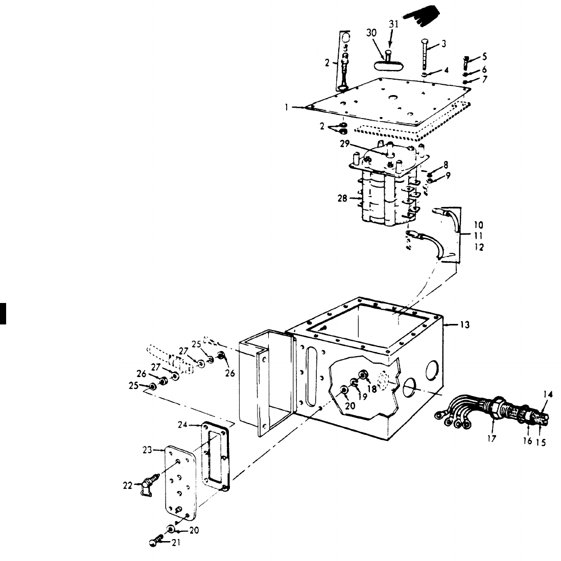
TM 5-6115-365-15
LEGEND TO PARTS, FIGURE 2-8
ITEM FUNCT ITEM
NO. GROUP NAME
14206 COVER
24206 LIGHT-WIRE
34206 SCREW
44206 PACKING
54206 SCREW
64206 WASHER
74018 WASHER
84206 WASHER
94206 NUT
10 4206 LEAD
11 4206 LEAD
12 4206 LEAD
13 4206 BOX
14 4206 CABLE
15 4206 CABLE
16 4206 STUFFING
17 4206 PACKING
18 4018 NUT
19 4018 WASHER
20 4018 WASHER
21 4018 SCREW
22 4018 TERMINAL LOAD
23 4018 TERMINAL BOARD
24 4018 GASKET
25 4018 WASHER
26 4018 NUT
27 4018 WASHER
28 4206 SWITCH
29 4206 PACKING
30 4206 KNOB
31 4206 SCREW, MACHINE
PAN HAND
Figure 2-8. Distribution box.
Change 11 2-25/(2-26 blank)
TM 5-6115-365-15
CHAPTER 3
GENERATOR SET PU-619/M
Section I. DESCRIPTION AND DATA
3-1. Description
a. General. Two 10 kW, model SF 10,0-MD
design) generator sets, mounted on 1-1/2 ton trailer,
model M 103A, constitute a self-contained mobile unit
referred to as Trailer Mounted Generator Set PU 619/M
(Refer to fig. 3-1). The two 10 kW generators are
powered by directly coupled four-cylinder, 20 hp military
standard model 4A084 engines. A power transfer switch
is provided for connecting the generators' output to a
common load. PU 619/M includes the components
listed below in Table 3-1.
b. Generators. For description and generator
operation and maintenance information not covered in
this chapter, refer to TM 5-6115-275-14.
c. Engines. For description and engine
maintenance information not covered in this chapter,
refer to TM 5-2805-259-14.
d. Trailer. For description and trailer maintenance
information not covered in this chapter, refer to
TM 9-2330-213-14.
e. Lubrication. Refer to LO 9-2330-213-12,
TM 5-6115-275-14, TM 5-2805-259-14 and
LO 5-2805-259-12 for all lubrication information required
for PU-619/M.
3-2. Tabulated Data
Table 3-1 lists the components for PU-619/M.
Table 3-1. ENPU-619/M Components.
FSN Qty Nomenclature
2330-141-8052 1Trailer: M103A
6115-075-1641 2Generator: 10 kW, Model SF
10.0-MD
2590-741-1037 1Leg prop assembly, trailer
2910-066-1235 2Adapter assembly, fuel drum
7240-222-3088 4Can, gasoline; military
5-gallon
4210-00-555-8837 2Fire extinguisher
5975-878-3791 2Ground rod (w/attachments)
5120-251-4489 1Sledge hammer
6115-00-459-5946 1Tarpaulin (Short Front)
6115-00-206-1271 1Tarpaulin (Long Front)
Change 10 3-1
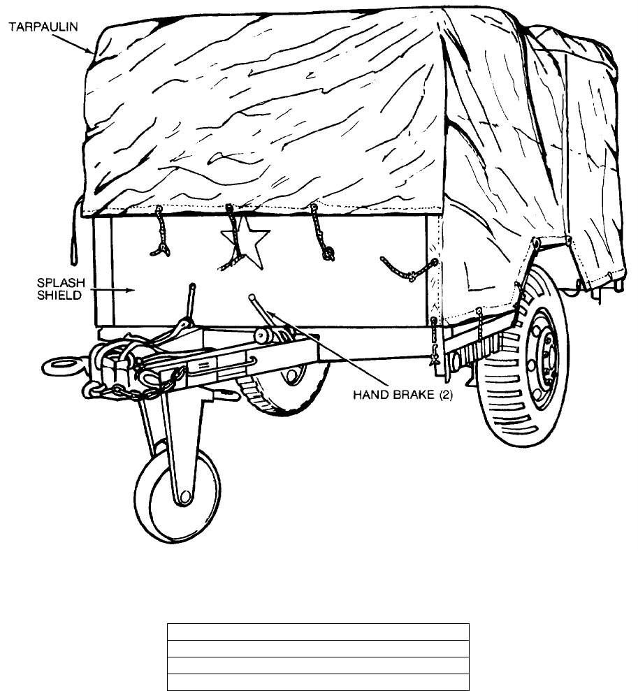
TM 5-6115-365-15
C1
CAUTION
KEEP TARPAULIN ROLLED UP DURING OPERATION AND BE CERTAIN TO
MAINTAIN THE MAXIMUM AMOUNT OF SPACE FOR VENTILATION AROUND THE
GENERATOR SETS WHEN OPERATING.
NOTE
ROLL UP TARPAULIN AND REMOVE
2 BOLTS AND 2 NUTS FROM TOP OF
SPLASH SHIELD. REMOVE SPLASH
SHIELD BEFORE OPERATING
EQUIPMENT.
SHIPPING DIMENSIONS:
LENGTH 174 INCHES
WIDTH 83 INCHES
HEIGHT 69 INCHES
WEIGHT 5,000 POUNDS
Figure 3-1. PU-619/M, left front, 3/4 view.
3-2

TM 5-6115-365-15
Section II. OPERATING INSTRUCTIONS
3-3. Setting-Up Instructions
a. Leveling.
(1) Locate the trailer on as level a surface as
possible in order for the generator sets to operate
efficiently.
(2) Set brakes and block wheels securely to
prevent any movement. Operate the handbrake at
weekly intervals to assure freedom of linkage.
(3) Pull leg support down and adjust length
for firm contact with ground.
Warning
Wheels must be blocked, brakes set,
and leg support down in support
position before attempting to roll up
the tarpaulin and before starting to
assemble or setup the equipment for
operation.
b. Preparation for Starting
(1) Roll up tarpaulin and remove splash shield
as instructed in figure 3-1.
(2) Remove all loose auxiliary items and
anything else that might block the free circulation of air
through the trailer and around the generator sets.
Caution
It is of foremost importance that
there be free circulation of air around
the generator sets at all times during
operation. Inadequate ventilation is a
major cause of damage to the
equipment.
(3) Be sure transfer switch load cables are
connected to the generator sets as illustrated in
figure 3-2.
c. Grounding.
Warning
Never operate the generator set until
it has been properly grounded.
Electrical defects in the load lines or
equipment can cause death by
electrocution when contact is made
with an ungrounded system.
(1) The generator set must be grounded prior
to operation. The ground may be any of three methods,
depending on the location and terrain.
(a) The ground rod driven to a depth of
8 feet.
(b) An underground metallic water
piping system.
(c) A metal plate (9 sq ft) buried at a
depth of 4 feet.
(2) The ground lead must be No. 6 AWG
copper wire bolted or clamped to the rod, plate, or piping
system.
(3) Connect the other end of the ground lead
to the generator set ground stud as shown in figure 3-3.
(4) Be sure that both generators are
connected to the generator set ground stud as shown in
figure 3-3.
d. Fuel Hose Connection. Connect the fuel hoses
as illustrated in figure 3-4.
Warning
Never operate the generator set in an
enclosed area unless the exhaust
gases are piped to the outside.
Inhalation of exhaust fumes will
result in serious illness or death.
3-4. Starting
a. Perform the setting-up and pre-starting
procedures (para 3-3).
b. Be sure the generator transfer switch is OFF
(fig. 3-2).
c. Start the generator set as instructed in
TM 5-6115-275-14.
3-5. Stopping
a. Turn generator transfer switch OFF or in position
to select standby generator (figure 3-2).
b. Stop the generator set as instructed in
TM 5-6115-275-14.
3-6. Operation
a. Start the generator (para 3-4) and position
transfer switch to desired generator.
b. Operate the generator as instructed in
TM 5-6115-275-14.
c. Perform the fuel transfer procedure as instructed
in figure 3-4.
Change 8 3-3
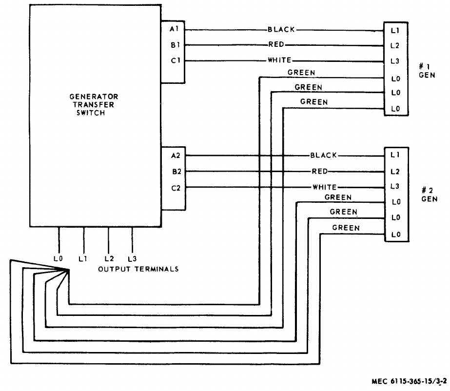
TM 5-6115-365-15
C1
Figure 3-2. Interconnection diagram, transfer switch-to-generator.
3-4
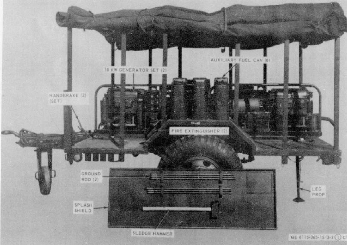
TM 5-6115-365-15
C1
Figure 3-3. PU-619/M set up for operation.
3-5
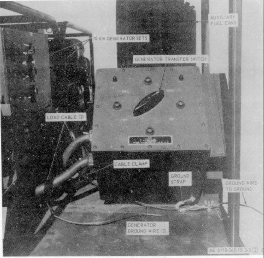
TM 5-6115-365-15
C1
Figure 3-3. Continued.
3-6
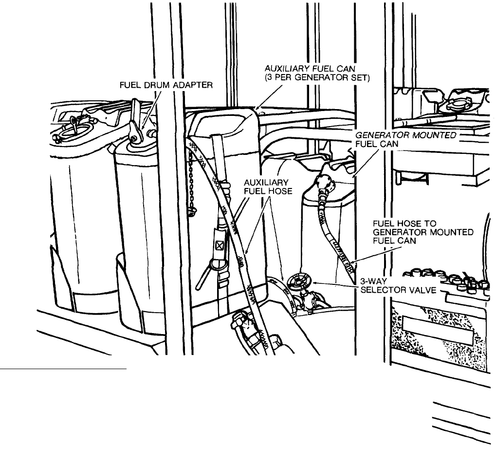
TM 5-6115-365-15
C1
WARNING
CLEAN UP ANY SPILLED FUEL immediately, AND LET FUMES EVAPORATE
BEFORE STARTING THE GENERATOR.
FUEL SYSTEM OPERATION
1. CONNECT THE AUXILIARY FUEL HOSE TO THE 3-WAY FUEL SELECTOR VALVE
AND CONNECT THE OTHER END TO THE ADAPTER INSTALLED IN ONE OF THE
5-GALLON AUXILIARY FUEL CANS.
2. POSITION THE SELECTOR VALVE TO DRAW FUEL FROM THE GENERATOR-MOUNTED
FUEL CAN. START THE GENERATOR AND BRING IT UP TO OPERATING SPEED.
3. POSITION THE SELECTOR VALVE TO DRAW FUEL FROM THE AUXILIARY FUEL CAN.
OPERATE THE GENERATOR FOR APPROXIMATELY 4 HOURS ON THE AUXILIARY FUEL
CAN, THEN TURN SELECTOR VALVE TO DRAW FUEL FROM THE GENERATOR-MOUNTED
FUEL CAN.
4. SWITCH THE ADAPTER TO ANOTHER AUXILIARY FUEL CAN AND TURN THE
SELECTOR VALVE BACK TO AUXILIARY FUEL SUPPLY POSITION.
NOTE
THIS PROCEDURE ELIMINATES NEED TO CHANGE FUEL CANS.
WARNING
DO NOT LET FUEL ADAPTERS COME IN CONTACT WITH THE BATTERIES.
Figure 3-4. Fuel system connection and transfer procedure. 3-7

TM 5-6115-365-15
Section III. OPERATOR'S MAINTENANCE INSTRUCTIONS
3-7. Transfer Switch Indicating Lamps
a. Removal. Remove lens and remove indicator or
lamp as illustrated in figure 3-8.
b. Installation. Install the indicator lamp and lens
as illustrated in figure 3-8.
3-8. Field Expedient Repairs
Trouble Probable cause Remedy
Power transfer switch Switch on terminal board Disconnect generator sets from
will not supply power defective transfer cables and connect load
to load cables directly to the individual
terminal boards of the generator sets
All data on Page 3-10, including Figure 3-5 deleted.
3-8 Change 8

TM 5-6115-365-15
Section IV. ORGANIZATIONAL MAINTENANCE INSTRUCTIONS
3-9. Transfer Switch Indicating Lights
a. Removal. Remove the indicating lights as
illustrated in figure 3-8.
b. Installation. Install the indicating lights as
illustrated in figure 3-8.
3-10. Ground Wires, Strap, and Terminal Stud
a. Removal. Remove the ground strap, and wires
from the ground terminal stud and generator set as
shown in figure 3-3. Remove the terminal stud.
b. Installation. Install the ground strap, wires and
terminal stud as shown in figure 3-3.
3-11. Tarpaulin, Roof Bows, and Leg Prop
a. Removal.
(1) Remove the tarpaulin from the unit.
(2) Pull out the chain-secured pins that
secure the roof bows to the trailer bed and remove the
bows.
(3) Remove the hardware that secures the leg
prop to the rear underside of the trailer bed and remove
the leg prop.
b. Cleaning and Inspection.
(1) Clean tarpaulin and bows with water and
detergent. Clean leg prop with approved cleaning
solvent. Dry thoroughly.
(2) Inspect tarpaulin for tears, holes, broken
or missing ropes and straps, and other defects. Inspect
bows and leg prop for cracks, bends, and any other
defects.
c. Installation.
(1) Mount the leg prop to the underside of the
trailer bed and secure with mounting hardware.
(2) Install the roof bows in the trailer bed and
secure with pins. Install the tarpaulin and secure in
desired position.
Section V. DIRECT AND GENERAL SUPPORT AND DEPOT
MAINTENANCE INSTRUCTIONS
3-12. Generator Transfer Switch
a. Removal and Disassembly.
(1) Tag and disconnect leads from the output
terminals to load.
(2) Remove and disassemble the transfer
switch as illustrated in figure 3-8.
b. Resassembly and Installation.
(1) Reassemble and install the transfer switch
as illustrated in figure 3-8.
(2) Connect load connections. (Refer to fig.
3-6).
3-13. Generator Sets
a. Removal. Using figure 3-7 as a guide, perform
the following steps:
(1) Disconnect fuel lines.
(2) Disconnect electrical leads and load
cables.
(3) Disconnect oil drain adapters.
(4) Remove 2 bolts and 2 nuts that secure the
muffler pipe on the front generator set to the trailer.
(5) Remove the 8 bolts that secure the two
generator sets to the trailer and remove the generator
sets.
b. Installation. Using figure 3-7 as a guide, perform
the following steps:
(1) Secure the 2 generator sets to the trailer
bed with 8 bolts.
(2) Secure the front muffler pipe to trailer bed
with 2 bolts and 2 nuts.
Change 8 3-11
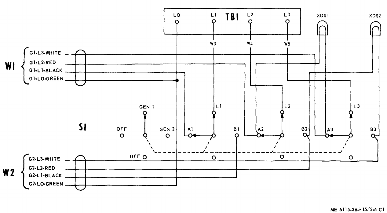
TM 5-6115-365-15
C1
Figure 3-6. Transfer switch wiring diagram.
3-12
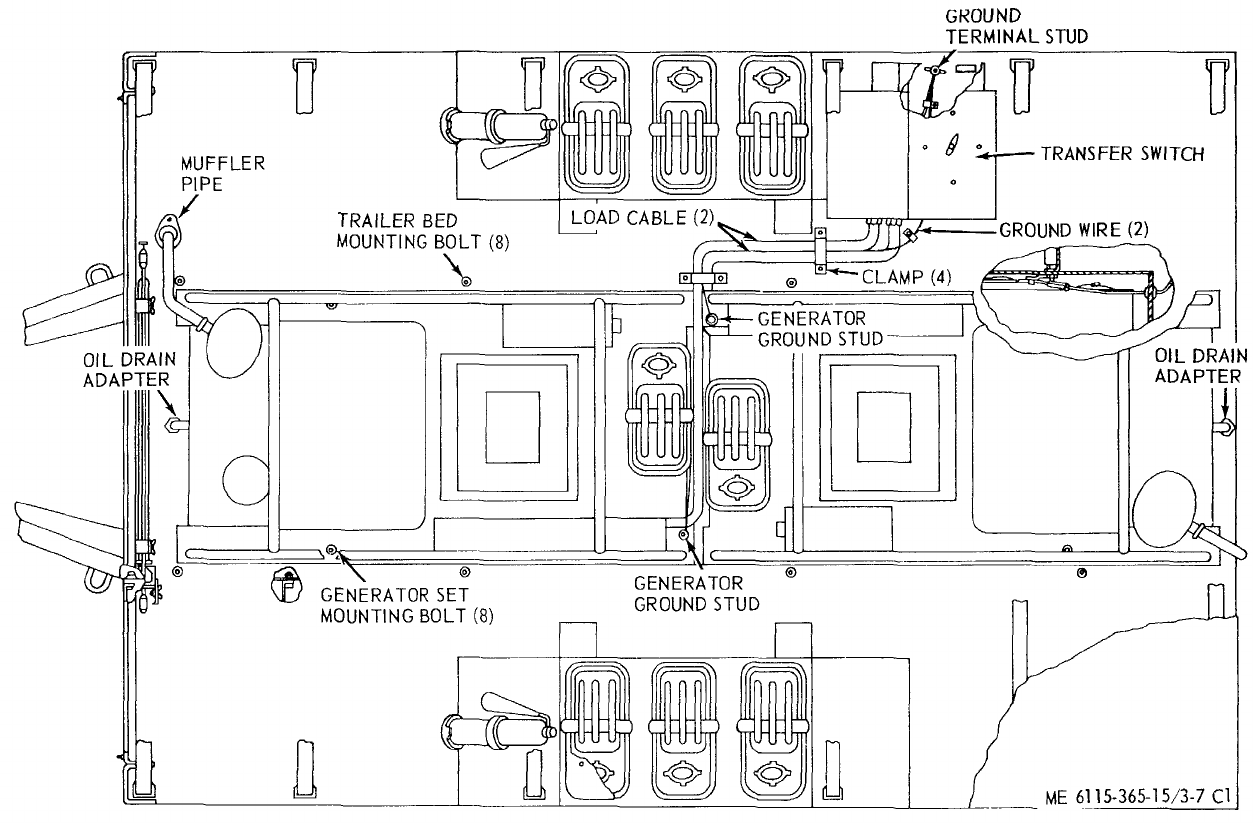
TM 5-6115-365-15
C1
Figure 3-7. PU-619M overall component location diagram.
3-13
TM 5-6115-365-15
C1
3-14. Tarpaulin, Roof Bows, and Leg Prop
a. Removal. Remove the tarpaulin, bows, and leg
prop (para. 3-11).
b. Repair.
(1) Patch or sew rips and tears in the
tarpaulin. Replace damaged or missing straps and
ropes. Replace a tarpaulin that is too badly damaged to
be repaired.
(2) Weld minor cracks and breaks in the bows
or leg prop. Straighten bows where possible. Replace
defective or missing hardware. Replace bows or leg
prop that are damaged beyond repair.
c. Installation. Install tarpaulin, bows, and leg prop
(para 3-11).
3-15. Trailer Bed
a. Removal.
(1) Remove the tarpaulin, roof bows, and leg
prop (para 3-11).
(2) Remove the transfer switch from trailer
(para 3-12).
(3) Remove the generator sets (para 3-13).
(4) Loosen straps and remove auxiliary fuel
cans from trailer.
(5) Remove 8 bolts from the top surface of
the trailer bed and 12 bolts from the underside that
secure the gussets to the trailer.
(6) Disconnect the electrical leads from the
trailer lights and remove the trailer bed from the trailer.
b. Cleaning, Inspection and Repair.
(1) Clean bed with approved cleaning solvent.
Dry thoroughly.
(2) Inspect for broken welds, bends and
dents, and any damage that prevents proper assembly
of the unit. Weld cracks and breaks and straighten
dents or bends where possible. Replace a trailer bed
that is damaged beyond repair.
c. Installation.
(1) Install trailer bed on trailer and secure with
12 bolts on the underside and 8 bolts on the top.
Connect wiring to lights.
(2) Install the generator sets (para 3-13).
(3) Install the transfer switch (para 3-12).
(4) Install the auxiliary fuel cans and secure
with straps.
(5) Install leg prop, roof bows, and tarpaulin
(para 3-11).
3-14
(1) (2) (3) (4) (5) (6) (7)
FEDERAL DESCRIPTION UNIT QTY 15-DAY ORGANIZATIONAL ILLUS-
SMR STOCK OF INC MAINTENANCE ALW RATION
CODE NUMBER USABLE MEAS IN (a) (b) (c) (d) (a) (b)
ON UNIT FIG ITEM
REF NUMBER & MFG CODE CODE 1-5 6-20 21-50 51-100 NO. NO.
TM 5-6115-365-15
C1
PART I
REPAIR PARTS FOR ORGANIZATIONAL MAINTENANCE
00001 GROUP 01 - ENGINE
00002 0106 - ENGINE LUBRICATION SYSTEM
O4730-766-7908 NIPPLE TUBE EA 2****
00003
O5310-282-7892 NUT, PLAIN, HEXAGON, RAIN HOSE EA 2 ****
00004
O5210-059-6372 WASHER, LOCK: oil drain union EA 2****
00005
00006 GROUP 15 - FRAME, TOWING ATTACHMENTS, AND DRAWBARS
00007 1501 - FRAME ASSEMBLY
X2 O7240-222-3088 BRACKET ASSEMBLY: 5 gallon EA 6
00008 MS53052-1 (96906)
X2 OBRACKET EA 6
00009 13214E1204 (97403)
X2 O5340-999-4286 BUCKLE EA 12
00010 MS51940-7 (96906)
X2 0FASTENER EA 6
00011 1314E1205 (97403)
X2 OHOOK, DRIP RAIL EA 6
13212E3616 (97403)
MOSTRAP, TOP: 30 in. lg EA 6
00013 13214E1203-2 (97403)
MANUFACTURE FROM:
PO5340-922-5653 STRAP, WEBBING FT SEE GRP 9501
00014 1403 (06716)
MOSTRAP, BOTTOM: 18 in. lg EA 6
00015 13214E1203-3 (97403)
MANUFACTURE FROM:
PO5340-922-5653 STRAP, WEBBING FT SEE GRP 9501
00016 1403 (06716)
X2 O5340-999-6277 BRACKET ASSEMBLY, SLEDGE HAMMER EA 1
00017 13214E1214 (97403)
X2 O2590-932-7298 CLAMP, GROUND ROD EA 4
00018 13212E3617-1 (97403)
X2 O5340-914-2578 CLIP, SPRING, TENSION EA 1
00019 13214E1213-1 (97403)
X2 ONUT, PLAIN, HEXAGON, JAM: 3/8-16 EA 3
00020 MS16203-39 (96906)
O5310-543-4717 NUT, PLAIN, WING, BRASS EA 1****
00021
O5310-088-1251 NUT, SELF-LOCKING, HEXAGON: 1/4 X 20 EA 2****
00022
O5310-088-1251 NUT, SELF-LOCKING, HEXAGON: 1/4 X 20 EA 1****
00023
O5310-088-1251 NUT, SELF-LOCKING, HEXAGON: 1/4 X 20 EA 8****
00024
O5310-087-4652 NUT, SELF-LOCKING, HEXAGON: 3/8 X 16EA 24 ****
00025
O5305-225-3839 SCREW, CAP, HEXAGON HEAD: 1/4 X 20 X 1 lg EA 2****
00026
O5305-225-3839 SCREW, CAP, HEXAGON HEAD: 1/4 X 20 X 1 lg EA 1****
00027
O5305-269-3213 SCREW, CAP, HEXAGON HEAD: 3/8 X 16 X 1-1/4 EA 24 ****
00028
O5305-958-5247 SCREW, MACHINE, FLAT HEAD: 1/2 X 20 X 1 lg EA 8****
00029
X2 O5340-00-878-5269 STUD: 3/8-16 X 2-1/2 EA 1
00030 13214E1223 (97403)
3-15
(1) (2) (3) (4) (5) (6) (7)
FEDERAL DESCRIPTION UNIT QTY
15-DAY ORGANIZATIONAL
ILLUS-
SMR STOCK OF INC MAINTENANCE ALW RATION
CODE NUMBER USABLE MEAS IN (a) (b) (c) (d) (a) (b)
ON UNIT FIG
ITEM
REF NUMBER & MFG CODE CODE 1-5 6-20
21-50
51-100
NO. NO.
TM 5-6115-365-15
X2 OWASHER, FLAT, ELECTRICAL- 3/8 thd size EA 4
00031 AN916-616T (88044)
O5310-809-4058 WASHER, FLAT: round EA 2****
00032
O5310-809-4058 WASHER, FLAT: round, 1/4 screw size EA 4****
00033
O5310-809-4058 WASHER, FLAT: round, 1/4 screw size EA 8****
00034
O5310-809-4061 WASHER, FLAT: round, 3/8 screw size EA 24 ****
00035
O5310-913-9776 WASHER, LOCK: external tooth, flat, 3/8 EA 2****
00036
00037 GROUP 18 - BODY, CAB, HOOD AND HULL
00038 1801 - BODY, CAB, HOOD, HULL ASSEMBLIES
O5310-080-8495 NUT, PLAIN. WING: 1/4 x 20 EA 2****
00039
X2 OPLATE, FRONT, SHIELD EA 1
00040 13216E7433 (97403)
O5305-721-8010 SCREW, CAP, HEXAGON HEAD: 1/4 x 20 x 2 Ig EA 2****
00041
O5310-809-4058 WASHER, FLAT: round, 1/4 screw size EA 4****
00042
O5310-933-8121 WASHER, LOCK: spring, helical, 1/4 screw EA 2****
00043
00044 1810 - CARGO BODY
X2 OBOLT, HEXAGON HEAD: 5/8-11 x 6-1/2 Ig EA 2
00045 FFB575 (97403)
O5310-269-4040 NUT, SELF-LOCKING, HEXAGON: 5/8 x 11 EA 8****
00046
O5310-087-4652 NUT, SELF-LOCKING, HEXAGON: 3/8 x 16 EA 12 ****
00047
O5305-269-3211 SCREW, CAP, HEXAGON HEAD: 3/8 x 16 x 1 Ig EA 16 ****
00048
O5305-724-5911 SCREW. CAP, HEXAGON HEAD 5/8-11 x 1-3/4 EA 6****
00049
X2 OSHIM (As required)
00050 13212E3590 (97403)
O5310-809-4061 WASHER, FLAT: round, 3/8 screw size EA 28 ****
00051
O5310-823-8803 WASHER, FLAT: round, 5/8 screw size EA 16 ****
00052
O5310-637-9541 WASHER, LOCK: spring, helical, 3/8 screw EA 4****
00053
00054 GROUP 22 - BODY CHASSIS OR HULL, AND ACCESSORY ITEMS
00055 2201 - CANVAS ITEMS
PO2540-924-8478 BOW, TRAILER TARPAULIN EA 4****
00056 13212E3597-1 (97403)
PO5340-00-878-5269 PIN, QUICK RELEASE EA
MS17990C613 (96906)
PO2540-926-1003 BOW, TRAILER TARPAULIN EA 2****
00057 13212E3597-2 (97403)
POR 6115-00-459-5946 TARPAULIN EA 1***2
00058 13216E7434 (97403)
00059 2202 - ACCESSORY ITEMS
X2 O7240-222-3088 CAN, GASOLINE,: 5-gallon military EA 6
00060 MILC1283 (81349)
PC5120-265-7462 HAMMER, HAND: double faced, 8 lb EA 1****
00061 GGGH86TYPEXCLASS1 (81348)
O5310-088-1251 NUT, SELF-LOCKING, HEXAGON: 1/4-20 EA 12 ****
00062
X2 O9905-202-3639 REFLECTOR, CLEARANCE: amber EA 2
00063 MS35387-2 (96906)
X2 O9905-205-2795 REFLECTOR, CLEARANCE: red EA 4
00064 MS35387-1 (96906)
3-16 Change 8

(1) (2) (3) (4) (5) (6) (7)
FEDERAL DESCRIPTION UNIT QTY
15-DAY ORGANIZATIONAL
ILLUS-
SMR STOCK OF INC MAINTENANCE ALW RATION
CODE NUMBER USABLE MEAS IN (a) (b) (c) (d) (a) (b)
ON UNIT FIG
ITEM
REF NUMBER & MFG CODE CODE 1-5 6-20
21-50
51-100
NO. NO.
TM 5-6115-365-15
C1
PC5975-642-8937 ROD, GROUND: Type 2, Style 2 EA 2****
00065 MILR11461TYPE2STYLE2 (81349)
X2 OSCREW, CAP, HEXAGON HEAD: 1/4-20 x 1 lg EA 12
00066 MS90725-5 (96906)
O5310-809-8546 WASHER, FLAT: round, 1/4 screw size EA 20 ****
00067
00068 2210 - DATA PLATES
X2 O6115-916-9734 PLATE, IDENTIFICATION EA 1
00069 13205E4916-3 (97403)
X2 OPLATE, IDENTIFICATION, GROUND TERMINAL EA 1
00070 13205E4918 (97403)
X2 OPLATE, INFORMATION WIRING, DIAGRAM EA 1
00071 13212E3587 (97403)
O5305-989-7434 SCREW, MACHINE, PAN HEAD: 10-32 x 1/2 EA 16 ****3-8 5
00072
O5310-809-4546 WASHER, FLAT: round, 10-32 screw size EA 16 ****3-8 7
00073
O5310-045-3296 WASHER, LOCK, HELICAL, SPLIT: No. 10 EA 16 ****3-8 6
00074
00075 GROUP 29 - AUXILIARY GENERATOR AND ENGINE AND CONTROLS
(SPECIAL PURPOSE)
00076 2941 - ENGINE MUFFLER, EXHAUST AND TAIL PIPES
X2 O6115-947-3380 EXHAUST TUBE EA 1
00077 13214E1238 (97403)
X2 O6115-934-7878 TUBE, EXHAUST EA 1
00078 13214E1389 (97403)
X2 O5340-940-7332 CLAMP ASSEMBLY EA 2
00079 13222Z3592-14 (97403)
O5310-088-1251 NUT, SELF-LOCKING, HEXAGON: 1/4 X 20 EA 2****
00080
O5305-225-3839 SCREW, CAP, HEXAGON HEAD: 1/4 X 20 X 1 lg EA 2****
00081
O5310-809-4058 WASHER, FLAT: round, 1/4 screw size EA 4****
00082
00083 GROUP 40 - ELECTRIC MOTORS AND GENERATORS
00084 4000 - GENERATOR ASSEMBLY
O5310-269-4040 NUT, SELF-LOCKING, HEXAGON: 5/8-11 EA 8****
00085
O5305-724-5911 SCREW, CAP, HEXAGON HEAD: 5/8 X 11 X 1-3/4 EA 8****
00086
O5310-823-803 WASHER, FLAT: round head, 5/8 screw EA 16 ****
00087
00088 GROUP 42 - ELECTRICAL EQUIPMENT
00089 4206 - THERMOSTATIC, AUTOMATIC AND MANUAL CONTROL DEVICES
X2 OLIGHT AND WIRE: 12 in. lg EA 13-8 2
00090 132123581-1 (9743)
O5310-225-6993 NUT, SELF-LOCKING, HEXAGON: 1/2-13 EA 4****3-8 10
00091
O5310-225-6993 NUT, SELF-LOCKING, HEXAGON: 1/2-13 EA 4****
00092
X2 O5330-618-5361 PACKING, PREFORMED, “O” RING EA 43-8 4
00093 MS28775-015 (96906)
X2 O5330-579-7916 PACKING, PREFORMED, “O” RING EA 13-8 32
00094 MS28775-115 (96906)
X2 OPACKING, PREFORMED, “O” RING EA 23-8 15
00095 MS28775-142 (96906)
X2 OPLATE, INFORMATION WIRING, DIAGRAM EA 1SEE GRP 2210
00096 13212E3587 (97403)
3-17

(1) (2) (3) (4) (5) (6) (7)
FEDERAL DESCRIPTION UNIT QTY
15-DAY ORGANIZATIONAL
ILLUS-
SMR STOCK OF INC MAINTENANCE ALW RATION
CODE NUMBER USABLE MEAS IN (a) (b) (c) (d) (a) (b)
ON UNIT FIG
ITEM
REF NUMBER & MFG CODE CODE 1-5 6-20
21-50
51-100
NO. NO.
TM 5-6115-365-15
C1
O5305-044-4153 SCREW, CAP, HEXAGON HEAD: 1/2-13 x 1 lg EA 4** * *
00097
O5305-983-7467 SCREW, CAP: socket head, 1/2-13unc-3A x 3 lg EA 4****3-8 3
00098
O5310-809-3079 WASHER, FLAT, ROUND, BOX MOUNTING: 1/2 screw size EA 8****
0099
O5310-809-5998 WASHER, FLAT: round, 1/2 in. screw EA 8****3-8 9
00100
00101 4216 - MISCELLANEOUS WIRING AND FITTING
X2 OCLAMP, CABLE, DOUBLE EA 2
00102 13212E3591-5 (97403)
X2 OCLAMP, CUSHIONED, SUPPORT LOOP: 1/8 EA 2
00103 MS21334-2 (96906)
O5310-918-6921 NUT, PLAIN, HEXAGON: jam EA 1****
00104
X2 ONUT, PLAIN, HEXAGON: machine screw, 10-24 EA 2
00105 MS35649-202 (96906)
O5310-088-1251 NUT, SELF-LOCKING, HEXAGON: 1/4-20 EA 4****
00106
O5305-071-2241 SCREW, CAP, HEXAGON HEAD: 1/4-20 X 1-1/4 EA 4****
00107
X2 OSCREW, CAP, HEXAGON HEAD: 3/8-16 X 3/4 lg EA 1
00108 MS35309-58 (96906)
O5305-984-6211 SCREW, MACHINE, PAN HEAD: 10-24 X 5/8 lg EA 2****
00109
O5310-809-4058 WASHER, FLAT: round, 1/4 thd size EA 8****
00110
O5310-809-8546 WASHER, FLAT: round, No. 10 screw size EA 4****
00111
O5310-913-9776 WASHER, LOCK: external tooth, flat, 3/8 EA 1****
00112
O5310-045-3296 WASHER, LOCK: spring, helical, No. 10 EA 2****
00113
MOWIRE, ELECTRICAL: No. 6, copper, uninsulated FT
00134 QQW343TYPERBCLASS1 (81348)
MANUFACTURE FROM:
PO6145-299-6188 WIRE, ELECTRICAL: copper, uninsulated, No. 6 (As
00115 required) FT SEE GRP 9501
QQW343TYPERBCLASS1 (81348)
00116 GROUP 76 - FIRE FIGHTING EQUIPMENT COMPONENTS
00117 7638 - PORTABLE FIRE FIGHTING EQUIPMENT
PC4210-555-8837 EXTINGUISHER, FIRE, W/BRACKET EA 2****
00118 MILE52031 (81349)
O5310-088-1251 NUT, SELF-LOCKING, HEXAGON: 1/4-20 EA 8****
00119
X2 OSCREW, CAP, HEXAGON: 1/4-20 X 5/8 lg EA 8
00120 MS90725-6 (96906)
O5310-809-8546 WASHER, FLAT: round, 1/4 screw size EA 16 ****
00121
00122 GROUP 95 - GENERAL USE STANDARDIZED PARTS
00123 9501 - HARDWARE SUPPLIES AND BULK MATERIAL, COMMON
PO5340-922-5653 WEBBING, STRAP FT ****
00124 1403 (06716)
PO6145-299-6188 WIRE, ELECTRICAL: No. 6, copper uninsulated FT ****
00125 QQW343TYPERBCLASS1 (81348)
3-18

(1) (2) (3) (4) (5) (6) (7) (8) (9) (10)
DESCRIPTION 1-YR
DEPOT
QTY 30-DAY DS MAINT 30-DAY GS MAINT ALW
PER MAINT
ALW ILLUS-
TRATION
FEDERAL USABLE UNIT INC ALLOWANCE ALLOWANCE 100 PER (a) (b)
SMR
CODE STOCK
NUMBER
ON
ref NUMBER & MFR CODE CODE OF
MEAS IN
UNIT (a)
1-20 (b)
21-50 (c)
51-100 (a)
1-20 (b)
21-50 (c)
51-100
EQUIP
CNTGCY 100
EQUIP FIG.
NO. ITEM
NO.
TM 5-6115-365-15
C1
PART II
REPAIR PARTS FOR DS, GS,
AND DEPOT MAINTENANCE
00001 GROUP 01 - ENGINE
00002 0106 - ENGINE LUBRICATION
SYSTEM
O4730-766-7908 NIPPLE TUBE EA 2******* *
00003
O5310-282-7822 NUT, PLAIN, HEXAGON, RAIN HOSE EA 2******* *
00004
O5310-059-6372 WASHER, LOCK: oil drain union EA 2******* *
00005
00006 GROUP 15 - FRAME, TOWING
ATTACHMENTS, AND DRAWBARS
00007 1501 FRAME ASSAULT
X2 O7240-222-3088 BRACKET ASSEMBLY: 5 gallon EA 6
00008 MS53052-1 (96906)
X2 OBRACKET EA 6
00009 13214E1204 (97403)
X2 O5340-999-4286 BUCKLE EA 12
00010 MS51940-7 (96906)
X2 OFASTENER EA 6
00011 13214E1205 (97403)
X2 OHOOK, DRIP RAIL EA 6
00012 13212E3616 (97403)
MOSTRAP, TOP: 30 in. lg EA 6
00013 13214E1203-2 (97403)
MANUFACTURE FROM:
PO5340-922-5653 STRAP, WEBBING FT SEE GRP 9501
00014 1403 (06716)
MOSTRAP, BOTTOM: 18 in. lg EA 6
00015 13214E1203-3 (97403)
MANUFACTURE FROM:
PO5340-922-5653 STRAP, WEBBING FT SEE GRP 9501
00016 1403 (06716)
X2 O5340-999-6277 BRACKET ASSEMBLY, SLEDGE HAMMER EA 1
00017 13214E1214 (97403)
X2 O2590-932-7298 CLAMP, GROUND ROD EA 4
00018 13212E3617-1 (97403)
X2 O5340-914-2578 CLIP, SPRING, TENSION EA 1
00019 13214E1213-1 (97403)
X2 ONUT, PLAIN, HEXAGON, JAM: 3/8-16 EA 3
00020 MS16203-39 (96906)
O5310-543-4717 NUT, PLAIN, WING, BRASS EA 1******* *
00021
O5310-088-1251 NUT, SELF-LOCKING, HEXAGON: 1/4 x 20 EA 2******* *
00022
O5310-088-1251 NUT, SELF-LOCKING, HEXAGON: 1/4 x 20 EA 1******* *
00023
O5310-088-1251 NUT, SELF-LOCKING, HEXAGON: 1/4 x 20 EA 8******* *
00024
O5310-087-4652 NUT, SELF-LOCKING, HEXAGON: 3/8 x 16 EA 24 ******* *
00025
O5305-225-3839 SCREW, CAP, HEXAGON HEAD: 1/4 x 20 x 1
00026 Ig EA 2******* *
O5305-225-3839 SCREW, CAP, HEXAGON HEAD: 1/4 x 20 x 1
00027 lg EA 1******* *
3-19

(1) (2) (3) (4) (5) (6) (7) (8) (9) (10)
DESCRIPTION 1-YR
DEPOT
QTY 30-DAY DS MAINT 30-DAY GS MAINT ALW
PER MAINT
ALW ILLUS-
TRATION
FEDERAL USABLE UNIT INC ALLOWANCE ALLOWANCE 100 PER (a) (b)
SMR
CODE STOCK
NUMBER
ON
ref NUMBER & MFR CODE CODE OF
MEAS IN
UNIT (a)
1-20 (b)
21-50 (c)
51-100 (a)
1-20 (b)
21-50 (c)
51-100
EQUIP
CNTGCY 100
EQUIP FIG.
NO. ITEM
NO.
TM 5-6115-365-15
C1
O5305-269-3213 SCREW, CAP, HEXAGON HEAD: 3/8 x 16 x
00028 1-1/4 EA 24 ******* *
O5305-958-5247 SCREW, MACHINE, FLAT HEAD: 1/4 x 20 x
00029 1 lg EA 8******* *
X2 OSTUD: 3/8-16 x 2-1/2 EA 1
00030 13214E1223 (97403)
X2 OWASHER, FLAT, ELECTRICAL: 3/8 thd size EA 4
00031 AN916-616T (88044)
O5310-809-4058 WASHER, FLAT: round EA 2******* *
00032
O5310-809-4058 WASHER, FLAT: round, 1/4 screw size EA 4******* *
00033
O5310-809-4058 WASHER, FLAT: round, 1/4 screw size EA 8*** *** *
00034
O5310-809-4061 WASHER, FLAT: round, 3/8 screw size EA 24 ******* *
00035
O5310-913-9776 WASHER, LOCK: external tooth, flat,
00036 3/8 EA 2******* *
00037 GROUP 18- BODY, CAB,
HOOD AND HULL
D0038 1801 - BODY, CAB, HOOD,
HULL ASSEMBLIES
O5310-080-8495 NUT, PLAIN, WING: 1/4 x 20 EA 2******* *
00039
X2 OPLATE, FRONT, SHIELD EA 1
00040 13212E3611-1 (97403)
O5305-721-8010 SCREW, CAP, HEXAGON HEAD: 1/4 x 20 x
00041 2 lg EA 2******* *
O5310-809-4058 WASHER, FLAT:round, 1/4 screw size EA 4******* *
00042
O5310-933-8121 WASHER, LOCK:spring, helical, 1/4
00043 screw EA 2******* *
00044 1810 - CARGO BODY
X2 DR BODY, TRAILER EA 1
00045 13214E1495 (97403)
X2 OBOLT, HEXAGON HEAD:5/8-11 x 6-1/2 lg EA 2
00046 FFB575 (97403)
X2 DR CHASSIS, TRAILER: M103A3 EA 1
00047 13212E3588-2 (97403)
O5310-269-4040 NUT, SELF-LOCKING, HEXAGON: 5/8 x 11 EA 8******* *
O0048
O5310-087-4652 NUT, SELF-LOCKING, HEXAGON: 3/8 x 16 EA 12 ******* *
00049
O5305-269-3211 SCREW, CAP, HEXAGON HEAD: 3/8 x 16 x 1
00050 lg EA 16 ******* *
O5305-724-5911 SCREW, CAP, HEXAGON HEAD: 5/8-11 x
00051 1-3/4 EA 6******* *
X2 OSHIM (As required)
00052 13212E3590 (97403)
O5310-809-4061 WASHER, FLAT: round, 3/8 screw size EA 28 ******* *
00053
O5310-823-8803 WASHER, FLAT: round, 5/8 screw size EA 16 ******* *
00054
O5310-637-9541 WASHER, LOCK: spring, helical, 3/8
00055 screw EA 4******* *
00056 GROUP 22 - BODY CHASSIS OR
HULL, AND ACCESSORY ITEMS
00057 2201 - CANVAS ITEMS
PO2540-924-8478 BOW, TRAIL TARPAULIN EA 4* * 2* * 288
00058 13212E3597-1 (97403)
3-20

(1) (2) (3) (4) (5) (6) (7) (8) (9) (10)
DESCRIPTION 1-YR
DEPOT
QTY 30-DAY DS MAINT 30-DAY GS MAINT ALW
PER MAINT
ALW ILLUS-
TRATION
FEDERAL USABLE UNIT INC ALLOWANCE ALLOWANCE 100 PER (a) (b)
SMR
CODE STOCK
NUMBER
ON
ref NUMBER & MFR CODE CODE OF
MEAS IN
UNIT (a)
1-20 (b)
21-50 (c)
51-100 (a)
1-20 (b)
21-50 (c)
51-100
EQUIP
CNTGCY 100
EQUIP FIG.
NO. ITEM
NO.
TM 5-6115-365-15
PO2540-926-1003 BOW, TRAILER TARPAULIN EA 2******4 4
00059 13212E3597-2 (97403)
POR 2540-914-2558 TARPAULIN EA 1*2 2 *2 2 13 13
00060 13212E3598 (97403)
MF2540-922-7651 STRAP, WEBBING: 16 x 3/4 x 18 Ig EA 8
00061 13212E3598-1 (97403)
MANUFACTURE FROM:
PF2540-914-2558 STRAP, WEBBING FT SEE GRP 9501
00062 13212E3598-1-2-3 (97403)
MF2540-914-2569 STRAP, WEBBING: 16 x 3/4 x 53 Ig EA 8
00063 13212E3598-2 (97403)
MANUFACTURE FROM:
PF2540-914-2558 STRAP, WEBBING FT SEE GRP 9501
00064 13212E3598-1-2-3 (97403)
MFSTRAP, WEBBING: 16 x 3/4 x 18-1/2 Ig EA 6
00065 13212E3598-3 (97403)
MANUFACTURE FROM:
PF2540-914-2558 STRAP, WEBBING FT SEE GRP 9501
00066 13212E3598-1-2-3 (97403)
X2 FSTRAP, WEBBING: 16 x 1 x 16 lg EA 12
00067 13212E3598-4 (97403)
X2 FSTRAP, WEBBING: 16 x 1 x 19-1/2 lg EA 12
00068 13212E3598-5 (97403)
X2 FTEE, HOOK EA 22
00069 13214E1498 (97403)
X2 F5340-057-6956 BUCKLE: spring action EA 12
00070 MS51929-2 (96906)
X2 FCHAPE ASSEMBLE EA 12
00071 13214E1392 (97403)
X2 F5340-078-7029 CLIP, END STRAP: black brass No. 1 EA 24
00072 MS51926-3 (96906)
X2 FDEE, RING: bronze EA 14
00073 MS51925-8 (96906)
X2 FROPE: sisal, nom dia, x 30 Ig EA 27
00074 13212E3598-11 (97403)
00075 2202 - ACCESSORY ITEMS
X2 O7240-222-3088 CAN, GASOLINE: 5-gallon military EA 6
00076 MILC1283 (81349)
PC5120-265-7462 HAMMER, HAND: double faced, 8 lb EA 1* * 2* * 2 10 10
00077 GGGH86TYPEXCLASS1 (81348)
O5310-088-1251 NUT, SELF-LOCKING, HEXAGON: 1/4-20 EA 12 ******* *
00078
X2 O9905-202-3639 REFLECTOR, CLEARANCE: amber EA 2
00079 MS35387-2 (96906)
X2 O9905-205-2795 REFLECTOR, CLEARANCE: red EA 4
00080 MS35387-1 (96906)
PC5975-642-8937 ROD, GROUND: Type 2, Style 2 EA 2* * 2* * 2 10 10
00081 MILR11461TYPE2STYLE2 (81349)
X2 OSCREW, CAP, HEXAGON HEAD: 1/4-20 x 1 g19 EA 12
00082 MS90725-5 (96906)
O5310-809-8546 WASHER, FLAT: round, 1/4 screw size EA 20 ******* *
00083
00084 2210 - DATA PLATES
X2 O6115-916-9734PLATE, IDENTIFICATION EA 1
00085 13205E4916-3 (97403)
Change 1 3-21
(1) (2) (3) (4) (5) (6) (7) (8) (9) (10)
DESCRIPTION 1-YR
DEPOT
QTY 30-DAY DS MAINT 30-DAY GS MAINT ALW
PER MAINT
ALW ILLUS-
TRATION
FEDERAL USABLE UNIT INC ALLOWANCE ALLOWANCE 100 PER (a) (b)
SMR
CODE STOCK
NUMBER
ON
ref NUMBER & MFR CODE CODE OF
MEAS IN
UNIT (a)
1-20 (b)
21-50 (c)
51-100 (a)
1-20 (b)
21-50 (c)
51-100
EQUIP
CNTGCY 100
EQUIP FIG.
NO. ITEM
NO.
TM 5-6115-365-15
X2 OPLATE, IDENTIFICATION, GROUND TERMINAL EA 1
00086 13205E4918 (97403)
X2 OPLATE, INFORMATION WIRING, DIAGRAM EA 1
00087 13212E3587 (97403)
O5305-989-7434 SCREW, MACHINE, PAN HEAD: 10-32 x 1/2
00088 Ig EA 16 ******* *3-8 5
O5310-809-8546 WASHER, FLAT: round, 10-32 screw size EA 16 ******* *3-8 7
00089
O5310-045-3296 WASHER, LOCK, HELICAL, SPLIT: No. 10
00090 size EA 16 ******* *3-8 6
00091 GROUP 29 - AUXILIARY GENERATOR
AND ENGINE AND CONTROLS
(SPECIAL PURPOSE)
00092 2941 - ENGINE MUFFLER,
EXHAUST AND TAIL PIPES
X2 O6115-947-3380 EXHAUST TUBE EA 1
00093 13214E1238 (97403)
X2 O6115-934-7878 TUBE, EXHAUST EA 1
00094 13214E1389 (97403)
X2 O5340-940-7332 CLAMP ASSEMBLY EA 2
00095 13212E3592-14 (97403)
O5310-088-1251 NUT, SELF-LOCKING, HEXAGON: 1/4-20 EA 2******* *
00096
O5305-225-3839 SCREW, CAP, HEXAGON HEAD: 1/4 x 20 x EA 2******* *
00097 1 Ig
O5310-809-4058 WASHER, FLAT: round, 1/4 screw size EA 4******* *
00098
00099 GROUP 40 - ELECTRIC MOTORS
AND GENERATORS
00100 4000 - GENERATOR ASSEMBLY
X2 FR 6115-792-8260 GENERATOR SET: Model 10KW60HZ EA 2
00101 MILG52280 (81349)
O5310-269-4040 NUT, SELF-LOCKING, HEXAGON: 5/8 x 11 EA 8******* *
00102
O5305-724-5911 SCREW, CAP, HEXAGON HEAD: 5/8 x 11 x
00103 1-3/4 EA 8******* *
O5310-823-8803 WASHER, FLAT: round head, 5/8 screw EA 16 ******* *
00104
00105 4018 - TERMINAL BLOCKS,
JUNCTION BOXES
X2 HGASKET, TERMINAL EA 1
00106 13212E3583 (97403)
X2 HTERMINAL BOARD EA 1
00107 13211E4775 (97403)
00108 GROUP 42 - ELECTRICAL EQUIPMENT
00109 4206 - THERMOSTATIC, AUTOMATIC
AND MANUAL CONTROL DEVICES
X2 FR 6110-913-9276 DISTRIBUTION BOX EA 1
00110 13212E3577 (97403)
X2 HBOX EA 13-8 19
00111 13212E3578 (97403)
X2 OPLATE, INFORMATION WIRING, DIAGRAM EA 1SEE GRP 2210
00112 13212E3587 (97403)
X2 H6150-01-160-5608 CABLE ASSEMBLY EA 1SEE GRP 4216 3-8 17
00113 13212E3584-1 (97403)
CABLE POWER 3-8 17A
LUG TERMINAL 3-8 17B
LUG TERMINAL 3-8 17C
INSULATION SLEEVING 3-8 170
INSULATING SLEEVING 3-8 17E
X2 H6115-01-088-3228 CABLE ASSEMBLY EA 1SEE GRP 4216 3-8 18
00114 13212E3585-1 (97403)
SAME AS CABLE ASSY P/N 13212E3584-1
3-22 Change 8
(1) (2) (3) (4) (5) (6) (7) (8) (9) (10)
DESCRIPTION 1-YR
DEPOT
QTY 30-DAY DS MAINT 30-DAY GS MAINT ALW
PER
MAINT
ALW ILLUS-
TRATION
FEDERAL USABLE
UNIT
INC ALLOWANCE ALLOWANCE 100 PER (a) (b)
SMR
CODE STOCK
NUMBER
ON
REF NUMBER & MFR CODE CODE OF
MEAS IN
UNIT (a)
1-20 (b)
21-50 (c)
51-100 (a)
1-20 (b)
21-50 (c)
51-100
EQUIP
CNTGCY 100
EQUIP
FIG.
NO.
ITEM
NO.
TM 5-6115-365-15
X2 F5940-943-7740 CONNECTOR, TERMINAL, POST EA 43-8 22
00115 13213E3949 (97403)
X2 FCOVER, DISTRIBUTION BOX EA 13-8 1
00116 13212E3579 (97403)
X2 HGASKET, TERMINAL BOARD EA 1SEE GRP 4018 3-8 20
00117 1321213583 (97403)
X2 HLEAD, ELECTRICAL EA 13-8 13
00118 13212E3586 (97403)
X2 HLEAD, ELECTRICAL EA 13-8 14
00119 13212E3586-3 (97403)
X2 HLEAD, ELECTRICAL EA 13-8 12
00120 13212E3586-1 (97403)
MF6150-01-152-8315 LEAD, ELECTRICAL EA 13-8 12
00112 13212E3586-1 (97403)
PF Terminal, Lug Crimp, copper insulated, Class 1, EA 13-8 12A
00120A Term Size 2, stud size 1/2
MS25036-128 (96906)
PF Terminal, Lug Crimp, copper insulated, Class 1. EA 13-8 12B
00120B Term Size 2, stud size 3/8
MS25036-127 (96906)
PE WIRE, Electrical, 600 volt, Copper aircraft, EA 13-8 12C
00120C 150 c, Type II, AN-2 per MIL-W-5086/2
MS5086/2-2-9 (96906)
X2 O6210-00-406-1398 LIGHT AND WIRE: 12 in. Ig EA 13-8 2
00121 13212E3581-1 (97403)
PAOOO 6240-00-892-4420 LAMP GLOW EA 13-8 2-A
MS25252-C7A (96906)
X2 H6210-00-253-0688 LIGHT AND WIRE: 17 in. Ig EA 13-8 8
00122 13212E3581-2 (97403)
PAOOO 6240-00-892-4420 LAMP GLOW EA 13-8 8A
MS25252-C7A (96906)
X2 HNUT, PLAIN, HEXAGON, BRASS: 3/8-24 EA 93-8 29
00123 MS20341-61a (96906)
X2 FNUT, PLAIN, HEXAGON, JAM EA 83-8 26
00124 MS16203-41 (96906)
O5310-225-6993 NUT, SELF-LOCKING, HEXAGON: 1/2-13 EA 4******* *3-8 10
000125
H5310-088-1251 NUT, SELF-LOCKING, HEXAGON: 1/4-20 EA 6* * * * * 3-8 28
00126
X2 O5330-618-5361 PACKING, PREFORMED "O" RING EA 43-8 4
00127 MS28775-015 (96906)
X2 O5330-579-7916 PACKING, PREFORMED "O" RING EA 13-8 32
00128 MS28775-115 (96906)
X2 OPACKING, PREFORMED "O" RING EA 23-8 15
00129 MS28775-142 (96906)
O5305-983-7467 SCREW, CAPsocket head, 1/2-13 unc-
00130 3A X 3 lg EA 4******* *3-8 3
H5305-988-1727 SCREW, MACHINE, PAN HEAD: 1/4-20 unc-
00131 2A x 1 lg EA 6* * * * * 3-8 23
H5305-954-9020 SCREW, MACHINE, PAN HEAD: 3/8-24 x
00132 3/4 Ig EA 9* * * * * 3-8 11
X2 HSTUFFING TUBE EA 23-8 16
00133 13212E5149-10 (97403)
X2 FSWITCH. ROTORAY: 200 amp EA 13-8 31
00134 13205E5024 (97403)
PA O5930-00-829-3243 KNOB EA 13-8 33
06000-1 (82121)
PA O5305-00-984-6210 SCREW, MACHINE PAN HAND EA 13-8 34
MS35206-263 (96906)
X2 HTERMINAL BOARD EA 1SEE GRP 4018 3-8 21
00135 13211E4775 (97403)
H5310-809-4058 WASHER, FLAT: round, steel, 1/4 screw
00136 size EA 12 * * * * * 3-8 24
X2 FWASHER, FLAT: round brass, 1/2 in. EA 83-8 27
00137 AN961-816T (88044)
Change 11 3-23
(1) (2) (3) (4) (5) (6) (7) (8) (9) (10)
DESCRIPTION 1-YR
DEPOT
QTY
30-DAY DS MAINT
30-DAY GS MAINT
ALW
PER MAINT
ALW ILLUS-
TRATION
FEDERAL USABLE UNIT INC ALLOWANCE ALLOWANCE 100 PER (a) (b)
SMR
CODE STOCK
NUMBER
ON
REF NUMBER & MFR CODE CODE OF
MEAS
IN
UNIT (a)
1-20 (b)
21-50 (c)
51-100 (a)
1-20 (b)
21-50 (c)
51-100
EQUIP
CNTGCY
100
EQUIP FIG.
NO. ITEM
NO.
TM 5-6115-365-15
O5310-809-5998 WASHER, FLAT: round, 1/2 in screw EA 8******* *3-8 9
00138
F5310-042-4229 WASHER, LOCK, FLAT: 1/2 in size EA 4******* *3-8 25
00139
H5310-913-9776 WASHER, LOCK, FLAT: external tooth, EA 9* * * * * 3-8 30
00140 3/8
O5310-225-6993 NUT, SELF-LOCKING, HEXAGON: 1/2-13 EA 4******* *
00141
O5305-044-4153 SCREW, CAP, HEXAGON HEAD: 1/2-13 x 1 Ig EA 4******* *
00142
X2 FTERMINAL LUG: 22-18 3/8, stud EA 4
00143 MS25036-105 (96906)
O5310-809-3079 WASHER, FLAT, ROUND, BOX MOUNTING: 1/2
00144 screw size EA 8******* *
00145 4216 - MISCELLANEOUS WIRING
AND FITTINGS
X2 H6115-01-160-5608 CABLE ASSEMBLY EA 1
00146 13212E3584-1 (97403)
PAFFF 5940-6-113-8191 LUG, TERMINAL: EA 3
MS25306-127 (96906)
PAFFF 5970-00-810-6003 INSULATION SLEEVING: FT V
MS23053/5-114-9 (81349)
PAFFF 6145-00-504-0218 CABLE, POWER: FV
C004HOE4-2 (81349)
X2 H6115-01-088-3228 CABLE ASSEMBLY EA 1
00147 13212E3585-1 (97403)
Same as Cable Assy. P/N 13212E3584-1
PAFFF 5940-00-113-9831 LUG TERMINAL: EA 1
MS-25036-128 (96906)
PAFFF 5970-822-2775 INSULATION SLEEVING: FT V
MS2305315-110-9
X2 OCLAMP, CABLE, DOUBLE EA 2
00148 13212E3591-5 (97403)
X2 OCLAMP, CUSHIONED, SUPPORT LOOP: 1/8 EA 2
00149 MS21334-2 (96906)
O3310-918-6921 NUT, PLAIN, HEXAGON: jam, 3/8-16 EA 1******* *
00150
X2 ONUT, PLAIN, HEXAGON: machine sew, 10-24 EA 2
00151 MS35649-202 (96906)
O5310-088-1251 NUT, SELF-LOCKING, HEXAGON: 1/4-20 EA 4******* *
00152
O5305-071-2241 SCREW, CAP, HEXAGON HEAD: 1/4-20 x EA 4******* *
00153 1-1/4
X2 OSCREW, CAP, HEXAGON HEAD: 3/8-16 x 3/4 Ig EA 1
00154 MS35309-58 (96906)
O5305-984-6211 SCREW, MACHINE, PAN HEAD: 10-24 x 5/8 EA 2******* *
00155 Ig
F5940-688-6010TERMINAL, LUG: NO. 6-3/8 stud EA 4******* *
00156
O5310-809-4058 WASHER, FLAT: round, 1/4 thd size EA 8******* *
00157
O5310-809-8546 WASHER, FLAT: round, No. 10 screw size EA 4******* *
00158
O5310-913-9776 WASHER, LOCK: external tooth, flat, 3/8 EA 1******* *
00159
O5310-045-3296 WASHER, LOCK: spring, helical, No. 10 EA 2******* *
00160
3-24 Change 11

(1) (2) (3) (4) (5) (6) (7) (8) (9) (10)
DESCRIPTION 1-YR
DEPOT
QTY
30-DAY DS MAINT
30-DAY GS MAINT
ALW
PER MAINT
ALW ILLUS-
TRATION
FEDERAL USABLE UNIT INC ALLOWANCE ALLOWANCE 100 PER (a) (b)
SMR
CODE STOCK
NUMBER
ON
REF NUMBER & MFR CODE CODE OF
MEAS
IN
UNIT (a)
1-20 (b)
21-50 (c)
51-100 (a)
1-20 (b)
21-50 (c)
51-100
EQUIP
CNTGCY
100
EQUIP FIG.
NO. ITEM
NO.
TM 5-6115-365-15
MOWIRE, ELECTRICAL: No. 6, copper, uninsulated FT
00161 QQW343TYPERBCLASS1 (81348)
MANUFACTURE FROM:
PO6145-299-6188 WIRE, ELECTRICAL: copper, uninsulated FT SEE GRP 9501
00162 No. 6 (As required)
QQW343TYPERBCLASS1 (81348)
00163 GROUP 76 - FIRE FIGHTING
EQUIPMENT COMPONENTS
00164 7638 - PORTABLE FIRE
FIGHTING EQUIPMENT
PC5210-555-8837 EXTINGUISHER, FIRE, W/BRACKET EA 2* * 2* * 2 10 10
00165 MILE52031 (81349)
O4310-088-1251 NUT, SELF-LOCKING, HEXAGON: 1/4-20 EA 8******* *
00166
X2 OSCREW, CAP, HEXAGON HEAD: 1/4-20 x 5/8 Ig EA 8
00167 MS90725-6 (96906)
O5310-809-8546 WASHER. FLAT: round, 1/4 screw size EA 16 ******* *
00168
00169 GROUP 95 - GENERAL USE
STANDARDIZED PARTS
00170 9501 - HARDWARE SUPPLIES
AND BULK MATERIAL COMMON
X2 FROPE: sisal, 3/8 FT
00171 13212E3598-11 (97403)
PF2540-914-2558 STRAP, WEBBING: 1-16 x 34 IN. FT *******35 35
00172 13212E3598-1-2-3 (97403)
PO5340-922-5653 WEBBING, STRAP FT *******8 8
00173 1403 (06716)
PO6145-299-6188 WIRE, ELECTRICAL: No. 6, copper,
00174 uninsulated FT ******** *
QQW343TYPERBCLASS1 (81348)
Change 8 3-25
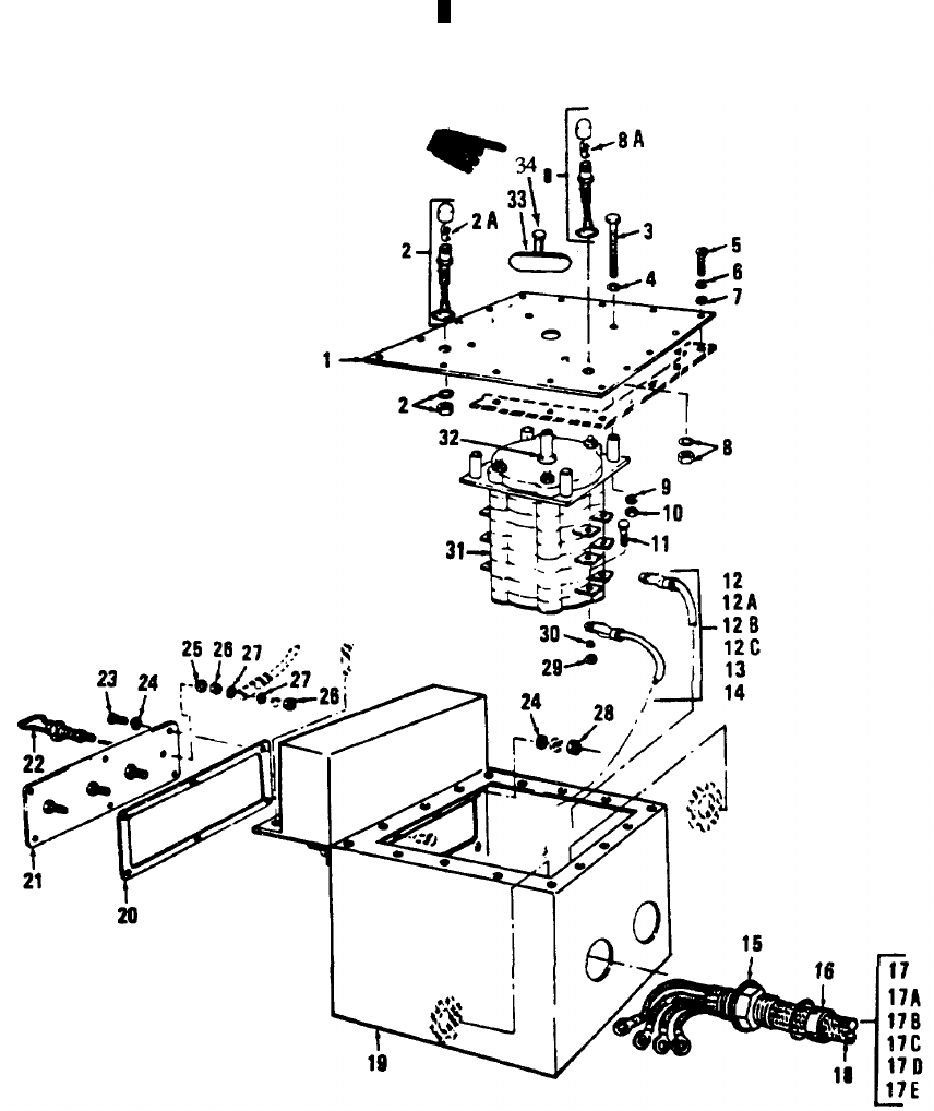
TM 5-6115-365-15
LEGEND TO PARTS, FIGURE 3-8
ITEM FUNCT ITEM
NO. GROUP NAME
1 4206 COVER
2 4206 LIGHT-WIRE
2A 4206 BULB
3 4206 SCREW
4 4206 PACKING
5 2210 SCREW
6 2210 WASHER
7 2210 WASHER
8 4206 LIGHT-WIRE
8A 4206 BULB
9 4206 WASHER
10 4206 NUT
11 4206 SCREW
12 4206 LEAD
12A 4206 TERMINAL
12B 4206 TERMINAL
12C 4206 WIRE
13 4206 LEAD
14 4206 LEAD
15 4206 PACKING
16 4206 STUFFING
17 4206 CABLE AY
17A 4206 CABLE POWER
17B 4206 LUG TERMINAL
17C 4206 LUG TERMINAL
17D 4206 INSULATION
SLEEVING
17E 4206 INSULATION
SLEEVING
18 4206 CABLE AY
19 4206 BOX
20 4206 GASKET
21 4206 TERMINAL BOARD
22 4206 CONNECTOR
23 4206 SCREW
24 4206 WASHER
ITEM FUNCT ITEM
NO. GROUP NAME
25 4206 WASHER
26 4206 NUT
27 4206 WASHER
28 4206 NUT
29 4206 NUT
30 4206 WASHER
31 4206 SWITCH
32 4206 PACKING
33 4206 KNOB
34 4206 SCREW, MACHINE,
PAN HAND
Figure 3-8. Distribution box.
3-26 Change 11
TM 5-6115-365-15
CHAPTER 4
GENERATOR SET PU-618/M AND PU-620/M
Section I. DESCRIPTION AND DATA
4-1. Description
a. General. The trailer mounted generator sets,
PU-618/M and PU-620/M, consist of two 5 kW, Model SF
5.0 Military Design generator sets mounted on a modified
1-1/2 ton, 2-wheel cargo trailer, Model 103A3 (PU-618/M),
or modified 3/4 ton, 2-wheel cargo trailer, Model M 116A 1
(PU-620/M), (refer to figures 4-1 and 4-2).
b. Generators. Each generator is powered by a
directly coupled, 2 cylinder, 10 hp, Military Standard
Model 2A042 engine. For description and generator
operation and maintenance, refer to TM 5-6115-332-14.
A power transfer switch is provided for connecting the
generators to a common load. Table 4-1 lists the
components of the PU-618/M and PU-6201M generator
sets.
c. Engines. For description and engine maintenance
information not covered in this chapter, refer to
TM 5-2805-258-14.
d. Trailers. For description and maintenance of the
trailer for PU-618/M, refer to TM 9-2330-213-14. For
PU-620/M trailer, refer to TM 9-2330-202-14.
e. Lubrication. For lubrication instructions refer to
TM 5-6115-332-14. For lubrication instructions for the
engines refer to TM 5-2805-258-14 and LO 52805-258-
12. The trailer lubrication information is contained in
LO 9-2330-21312 (PU-618/M) and LO 9-2330-202-12
(PU-620/M).
4-2. Tabulated Data
Table 4-1 lists components for PU-618/M and PU-620/M
generator sets.
Table 4-1. PU-618-M and PU-620/M components.
FSN QTY Nomenclature
2330-141-8052 1Trailer; M103A3 (PU-618/M)
2330-898-6780 1Trailer; M116A1 (PU-620/M)
2590-420-8929 1Leg prop assembly, trailer
6115-017-8240 or 2Generator; 5 kW, Model SF 5.0 MD
6115-074-8330 2Generator; 5 kW, MEP-017A
2910-066-1235 4Adapter assembly, fuel drum
7240-222-3088 6Can, gasoline; military, 5-gallon
4210-00-555-8837 2Fire Extinguisher
5975-878-3791 2Ground rod w/attachments
5120-215-4489 1Sledge hammer
2540-00-926-0993 1Tarpaulin
Change 10 4-1
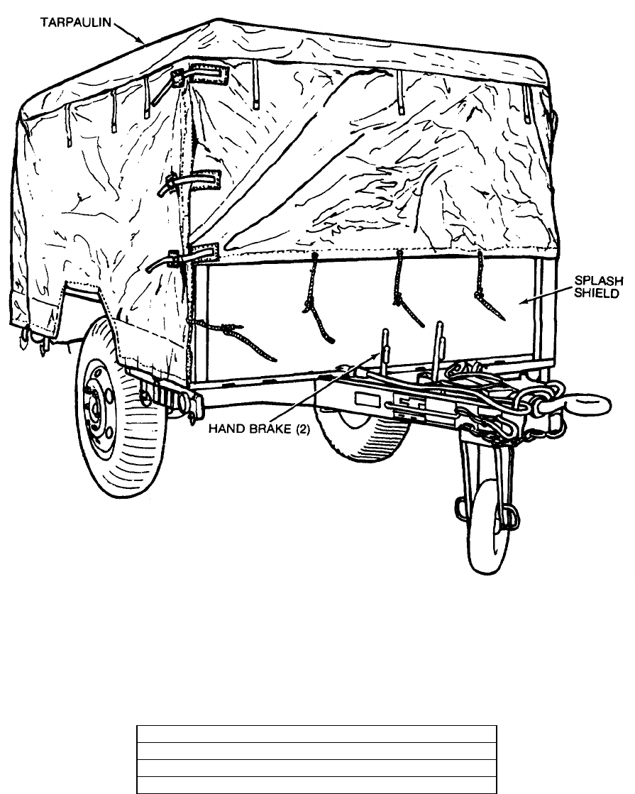
TM 5-6115-365-15
NOTE
ROLL UP TARPAULIN AND REMOVE 2 BOLTS AND 2 NUTS FROM TOP OF
SPLASH SHIELD. REMOVE SPLASH SHIELD BEFORE OPERATING EQUIPMENT.
SHIPPING DIMENSIONS
LENGTH 175 INCHES
WIDTH 83 INCHES
HEIGHT 66 INCHES
WEIGHT 4,360 POUNDS
Figure 4-1. PU-618/M, right front, 3/4 view.
4-2
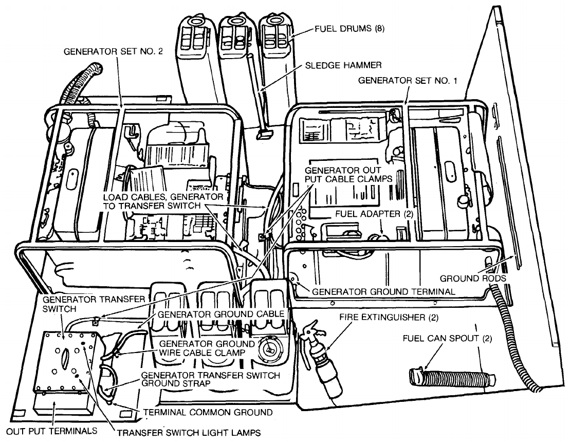
TM 5-6115-365-15
C1
Figure 4-2. PU-620/M, top view, tarpaulin removed.
4-3

TM 5-6115-365-15
Section II. OPERATING INSTRUCTIONS
4-3. Setting-Up Instructions
a. Leveling.
(1) Locate the trailer on as level a surface as
possible in order for the generator sets to operate
efficiently.
(2) Set brakes and block wheels securely to
prevent any movement. Operate the handbrake at
weekly intervals to assure freedom of linkage.
(3) Pull the leg support down and adjust
length for firm contact with ground.
Warning
Wheels must be blocked, brakes set,
and leg prop down in support
position before attempting to roll up
the tarpaulin and before starting to
setup or assemble the equipment for
operation.
b. Preparation for Starting.
(1) Roll up tarpaulin and remove splash shield
as shown in figure 4-1.
Caution
It is of foremost importance that
there be free circulation of air around
the generator sets at all times during
operation. Inadequate ventilation is a
major cause of damage to the
equipment.
(2) Remove all loose auxiliary items and
anything else that might block the free circulation of air
through the trailer and around the generator sets.
Caution
Before starting either generator set,
check that the output selector
switches located in the control boxes
of both generator sets, are positioned
to the same generator output setting
(i.e., the same selector switch
setting) denoting voltage, phase, and
number of wires. Failure to check the
selector switch setting could result in
damage to the connected equipment.
(3) Be sure transfer switch load cables are
connected to the generator sets as illustrated in figure 4-3.
c. Grounding.
Warning
Never operate the generator set until
it has been properly grounded.
Electrical defects in the load lines or
equipment can cause death by
electrocution when contact is made
with an underground system.
(1) The generator set must be grounded prior
to operation. The ground may be any of three methods,
depending on the location and terrain.
(a)The ground rod driven to a depth of
8 feet.
(b) An underground metallic water
piping system.
(c) A metal plate (9 sq ft) buried at a
depth of 4 feet.
(2) The ground lead must be No. 6 AWG
copper wire bolted or clamped to the rod, plate, or piping
system.
(3) Connect the other end of the ground lead
to the generator set ground stud as shown in figure 4-4.
(4) Be sure that both generators are
connected to the generator set ground stud as shown in
figure 4-4.
d. Fuel Hose Connection. Connect the fuel hoses
as illustrated in figure 4-5.
Warning
Never operate the generator set in an
enclosed area unless the exhaust
gases are piped to the outside.
Inhalation of exhaust fumes will
result in serious illness or death.
4-4. Starting
a. Perform setting-up and pre-starting procedures
(para 4-3).
b. Be sure generator transfer switch is OFF
(Fig. 4-3).
c. Start the generator set as instructed in
TM 5-6115-332-12.
4-5. Stopping
a. Turn generator transfer switch OFF or in position
to select standby generator (Fig. 4-3).
b. Stop the generator set as instructed in
TM 5-6115-332-12.
4-6. Operation
a. Start the generator (para 4-4) and position
transfer switch to desired generator.
b. Operate the generator as instructed in
TM 5-6115-332-12.
c. Perform the fuel transfer procedure as instructed
in figure 4-5.
4-4 Change 8
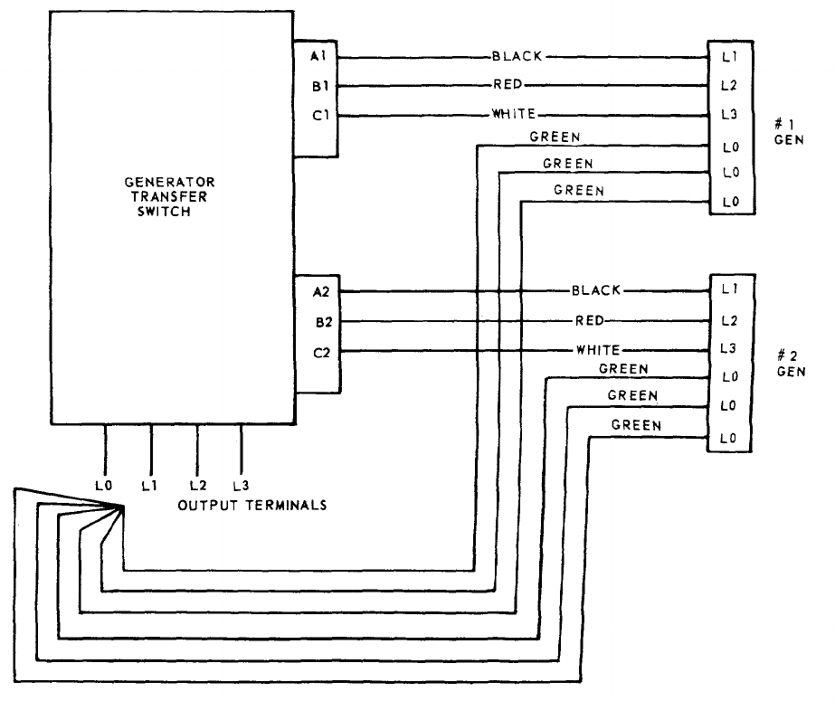
TM 5-6115-365-15
C1
MEC 6115-365-15/4-3
Figure 4-3. Interconnection diagram, transfer switch-to-generators.
4-5
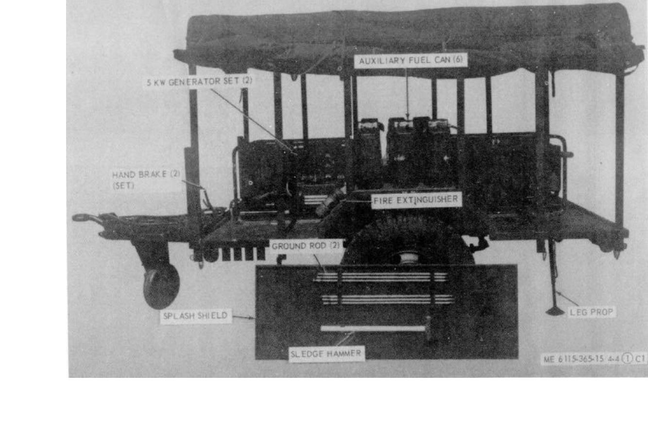
ME 6115-365-15/4-4 (1) C1
TM 5-6115-365-15
C1
CAUTION
KEEP TARPAULIN ROLLED UP DURING OPERATION AND BE CERTAIN TO MAINTAIN THE MAXIMUM AMOUNT OF
SPACE AROUND THE GENERATORS SO AIR CIRCULATES FREELY AT ALL TIMES.
Figure 4-4. PU-618M set up for operation.
4-6
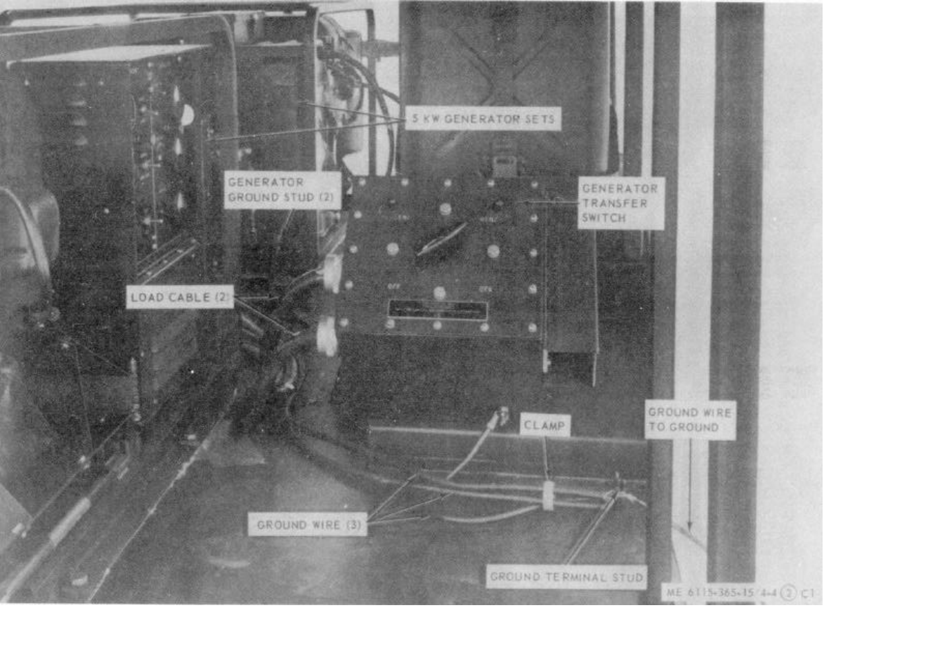
ME 6115-365-15/4-4 (2) C1
TM 5-6115-365-15
C1
Figure 4-4. Continued.
4-7
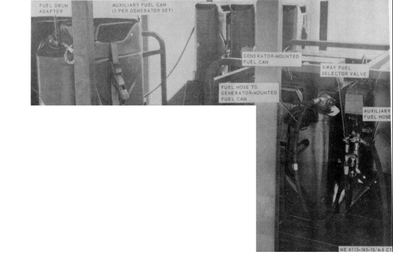
ME 6115-365-15/4-5 C1
TM 5-6115-365-15
C1
FUEL SYSTEM OPERATION:
1. CONNECT THE AUXILIARY FUEL HOSE TO THE 3-WAY FUEL SELECTOR VALVE AND
CONNECT THE OTHER END TO THE ADAPTER INSTALLED in ONE OF THE 5-GALLON
AUXILIARY FUEL CANS.
2. POSITION SELECTOR VALVE TO DRAW FUEL FROM THE GENERATOR-MOUNTED
FUEL CAN. START THE GENERATOR AND BRING IT UP TO OPERATING SPEED.
3. POSITION SELECTOR VALVE TO DRAW FUEL FROM THE AUXILIARY FUEL CAN.
OPERATE GENERATOR FOR APPROXIMATELY 4 HOURS ON THE AUXILIARY FUEL
CAN, THEN TURN SELECTOR VALVE TO DRAW FUEL FROM THE GENERATOR-
MOUNTED FUEL CAN.
4. SWITCH THE ADAPTER TO ANOTHER AUXILIARY FUEL CAN DURING THE SELECTOR
VALVE BACK TO AUXILIARY FUEL SUPPLY POSITION.
NOTE
THIS PROCEDURE ELIMINATES NEED TO CHANCE FUEL CANS.
WARNING
CLEAN UP ANY SPILLED FUEL IMMEDIATELY AND LET FUMES EVAPORATE BEFORE
STARTING THE GENERATOR.
WARNING
DO NOT LET FUEL DRUM ADAPTERS COME IN CONTACT WITH THE BATTERIES.
Figure 4-5. Fuel system connection and transfer procedure.
4-8

TM 5-6115-365-15
C1
Section III. OPERATOR'S MAINTENANCE INSTRUCTIONS
4-7. Transfer Switch Indicating Lamps
a. Removal. Remove lens and remove indicator
lamp as illustrated in figure 4-6.
b. Installation. Install the indicator lamp and lens
as illustrated in figure 4-6.
4-8. Field Expedient Repairs
Trouble Probable cause Remedy
Power transfer switch Switch on terminal board Disconnect generator
will not supply power defective. from transfer cables
to load. and connect load
cables directly to
the individual ter-
minal boards of the
generator sets.
4-9
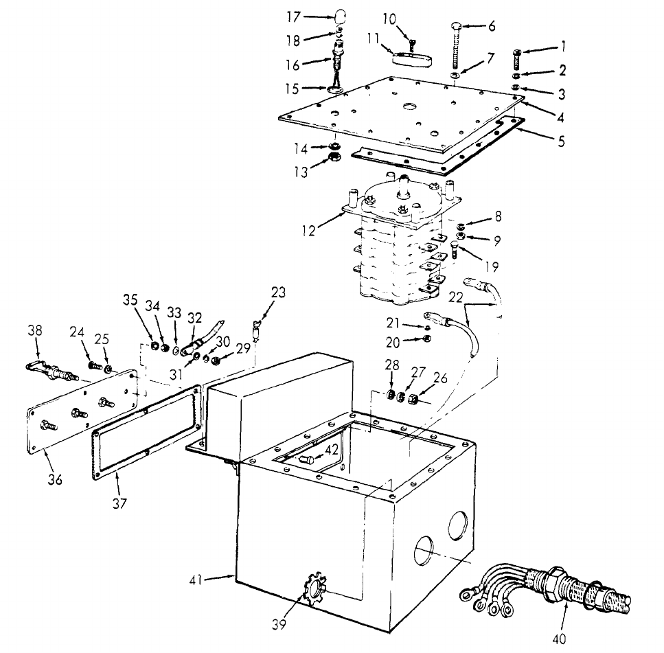
TM 5-6115-365-15
C1
ME 6515-365-15/4-6 C1
1Screw 9Hexnut 17 Lens
2Lockwasher 10 Screw 18 Lamp
3Flatwasher 11 Knob 19 Screw
4Cover 12 Transfer switch 20 Hexnut
5Gasket 13 Hexnut 21 Lockwasher
6Screw 14 Lockwasher 22 Electrical lead
7Flatwasher 15 Preformed packing 23 Fastener
8Lockwasher 16 Light and wire assembly 24 Screw
Figure 4-6. Transfer switch, removal, disassembly, reassembly, and installation.
4-10

TM 5-6115-365-15
C1
25 Flatwasher 31 Flatwasher 37 Gasket
26 Hexnut 32 Electrical lead 38 Terminal lug
27 Lockwasher 33 Flatwasher 39 Locknut
28 Flatwasher 34 Hexnut 40 Stuffing tube assembly
29 Hexnut 35 Lockwasher 41 Transfer switch box
30 Lockwasher 33 Terminal board 42 Rivet
Figure 4-6-Continued.
Section IV. ORGANIZATIONAL MAINTENANCE INSTRUCTIONS
4-9. Transfer Switch Indicating Lights
a. Removal. Remove the indicating lights as
illustrated in figure 4-6.
b. Installation. Install the indicating lights as
illustrated in figure 4-6.
4-10. Ground Wires, and Terminal Stud
a. Removal. Remove the ground wires from the
ground terminal stud and generator sets as shown in
figure 4-4. Remove the terminal stud.
b. Installation. Install the ground wires, and
terminal stud as shown in figure 4-4.
4-11. Tarpaulin, Roof Bows, and Leg Prop
a. Removal.
(1) Remove the tarpaulin from the unit.
(2) Pull out the chain-secured pins that
secure the roof bows to the trailer bed and re- move the
bows.
(3) Remove the hardware that secures the leg
prop to the rear underside of the trailer bed and remove
the leg prop.
b. Cleaning and Inspection.
(1) Clean tarpaulin and roof bows with water
and detergent. Clean leg prop with approved cleaning
solvent. Dry thoroughly.
(2) Inspect tarpaulin for tears, holes, broken
or missing ropes or straps and other defects. Inspect
bows and leg prop for cracks, bends, and any other
defects.
c. Installation.
(1) Mount the leg prop to the underside of the
trailer bed and secure with mounting hardware.
(2) Install the roof bows in the trailer bed and
secure with pins. Install the tarpaulin and secure in the
desired position.
Section V. DIRECT AND GENERAL SUPPORT AND DEPOT
MAINTENANCE INSTRUCTIONS
4-12. Generator Transfer Switch
a. Removal and Disassembly.
(1) Tag and disconnect leads from the output
terminals to load.
(2) Remove and disassemble the transfer
switch as illustrated in figure 4-6.
b. Reassembly and Installation.
(1) Reassemble and install the transfer switch
as illustrated in figure 4-6.
(2) Connect load connections. (Refer to
figure 4-7).
4-13. Generator Sets
a. Removal. Use figure 4-8 as a guide and
perform the following steps:
(1) Disconnect fuel lines.
(2) Disconnect electrical leads and cables.
(3) Disconnect oil drain adapters.
(4) Remove 2 bolts and 2 nuts that secure the
front muffler pipe to the trailer and remove pipe.
(5) Remove the 8 bolts (4 to each set) that
secure the generator sets to the trailer and remove the
generator sets.
b. Installation. Using figure 4-8 as a guide, perform
the following steps:
(1) Secure the two generator sets to the
trailer bed with 8 bolts.
(2) Secure front muffler pipe to trailer bed with
2 bolts and 2 screws.
4-11
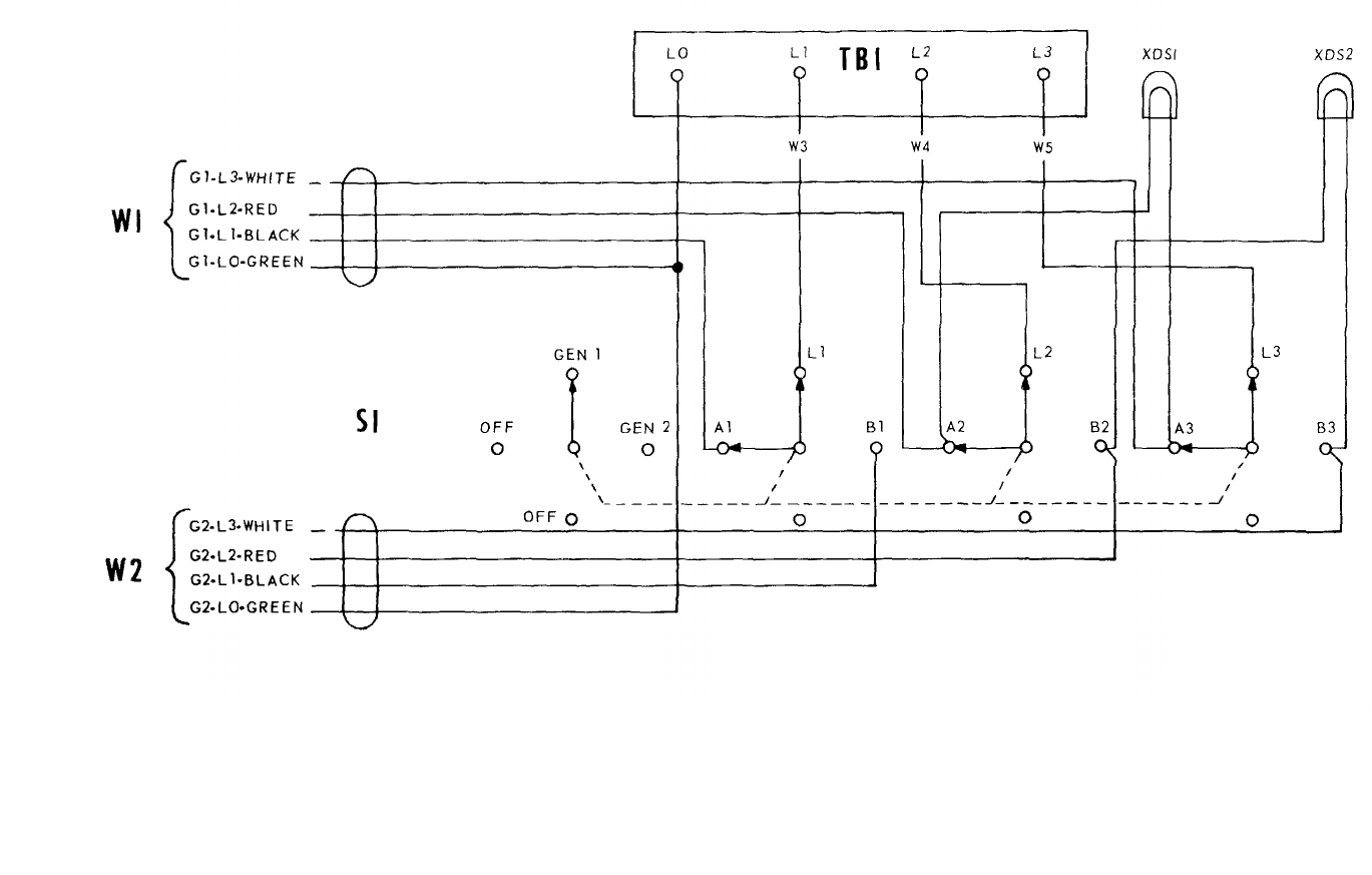
TM 5-6115-365-15
C1
Figure 4-7. Transfer switch wiring diagram.
4-12
ME 6115-365-15/2-6 C1
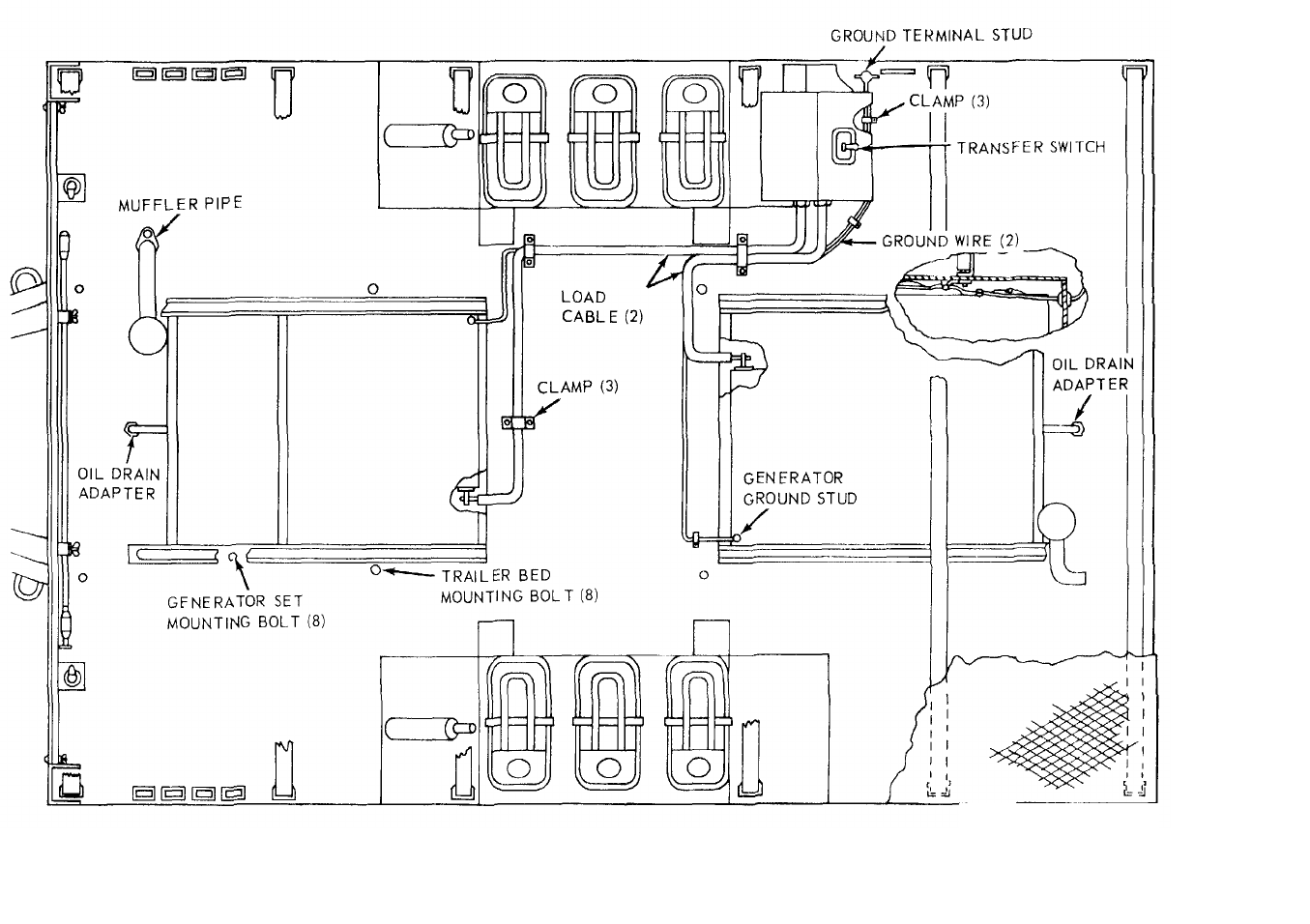
TM 5-6115-365-15
C1
Figure 4-8. PU-618M overall component location diagram.
4-13
ME 6115-365-15/4-8 C1
TM 5-6115-365-15
C1
4-14. Tarpaulin, Roof Bows, and Leg Prop
a. Removal. Remove the tarpaulin, roof bows,
and leg prop (para 4-11).
b. Repair.
(1) Patch or sew rips and tears in the
tarpaulin. Replace damaged or missing straps and
ropes. Replace a tarpaulin that is too badly damaged to
be repaired.
(2) Weld minor cracks and breaks in the roof
bows and leg prop. Straighten bows where possible.
Replace defective or missing hardware. Replace bows
or leg prop that are damaged beyond repair.
c. Installation. Install the tarpaulin, roof bows, and
leg prop (para 4-11).
4-15. Trailer Bed
a. Removal.
(1) Remove the tarpaulin, roof bows and leg
prop (para 4-11).
(2) Remove the transfer switch from the trailer
(para 4-12).
(3) Remove the generator sets (para 4-13).
(4) Loosen straps and remove the auxiliary
fuel cans from trailer.
(5) Remove 8 bolts from the top surface of
the trailer bed and 12 bolts from the underside that
secure the trailer bed gussets to the trailer.
(6) Disconnect electrical leads from the trailer
lights. (7) Remove the trailer bed from the trailer.
b. Cleaning, Inspection, and Repair.
(1) Clean trailer bed with approved
cleaning solvent and dry thoroughly.
(2) Inspect for broken welds, bends, and
dents, and any damage that prevents proper assembly
of the unit. Weld cracks and breaks and straighten
dents or bends where possible. Replace a trailer bed
that is damaged beyond repair.
c. Installation.
(1) Install trailer bed on the trailer and secure
with 12 bolts on the underside and 8 bolts on the top.
Connect wiring to trailer lights.
(2) Install the generator sets (para 4-13).
(3) Install the transfer switch (para 4-12).
(4) Install fuel cans and secure with straps.
(5) Install leg prop, bows, and tarpaulin
(para 4-11).
4-14

(1) (2) (3) (4) (5) (6) (7)
FEDERAL DESCRIPTION UNIT QTY 15-DAY ORGANIZATIONAL ILLUS-
SMR STOCK OF INC MAINTENANCE ALW RATION
CODE NUMBER USABLE MEAS IN (a) (b) (c) (d) (a) (b)
ON UNIT FIG ITEM
REF NUMBER & MFG CODE CODE 1-5 6-20 21-50 51-100 NO. NO.
TM 5-6115-365-15
C1
PART I
REPAIR PARTS FOR ORGANIZATIONAL MAINTENANCE
00001 GROUP 01 - ENGINE
00002 0106 - ENGINE LUBRICATION SYSTEM
X2 O4720-913-6422 HOSE, OIL DRAIN EA 2
00003 13211E4918 (97403)
O4730-766-7908 NIPPLE, UNION: OIL DRAIN EA 2****
00004
O5310-282-7822 NUT, UNION: oil drain hose EA 2****
00005
X2 OREDUCER, BUSHING: 3/4-14 X 1/2-14 EA 2
00006 SAEJ530 (81343,
O5310-754-2005 WASHER, LOCK: oil drain hose EA 2****
00007
00008 GROUP 15 - FRAME, TOWING ATTACHMENTS, AND DRAWBARS
00009 1501 - FRAME ASSEMBLY
X2 O2590-473-6331 BRACKET ASSEMBLY: liquid count, 5 gallon EA 6
00010 MS53052-1 (96906)
X2 OBRACKET EA 6
00011 13214E1204 (97403)
X2 O5340-999-4286 BUCKLE EA 12
00012 MS51940-7 (96906)
X2 OFASTENER EA 6
00013 13214E1205 (97403)
X2 OHOOK, DRIP RAIL EA 6
00014 13212E1316 (97403)
MOSTRAP: bottom, 18 in. lg, nylon webb EA 6
000151 13214E1203-3 (97403)
MANUFACTURE FROM:
PO5340-922-5653 WEBBING NYLON FT SEE GRP 9501
00016 MILW530TYPE2CLASSA (81349)
MOSTRAP: top, 30 in. lg, nylon webb EA 6
00017 13214F1203-2 (97403)
MANUFACTURE FROM:
PO5340-922-5653 WEBBING, NYLON FT SEE GRP 9501
00018 1403 (06716)
X2 O5340-999-6277 BRACKET ASSEMBLY: sledge hammer EA 1
00019 13214E1214 (97403)
X2 OCLAMP CABLE: double EA 1
0002O 13212E3591-2 (97403)
X2 OCLAMP CABLE: single EA 2
00021 1321E3612 (97403)
X2 O5340-526-2559 CLAMP, CUSHIONED SUPPORT: loop type EA 1
00022 MS21333-2 (96906)
X2 O2590-932-7298 CLAMP, GROUND ROD EA 4
00023 13212E3617-1 (97403)
X2 O5340-914-2578 CLIP, SPRlNG EA 1
00024 13214E1213-1 (97403)
X2 O7240-920-5327 HOLDER, FUEL ADAPTER EA 2
00025 13212E3553-1 (97403)
O5310-934-9758 NUT, PLAIN, HEXAGON: No. 10-24 EA 1****
00026
O5310-088-1251 NUT, SELF-LOCKING, HEXAGON: 1/4-2O EA 8****
00027
O5310-088-1251 NUT, SELF-LOCKING, HEXAGON: 1/4-2O EA 2****
00028
4-15
(1) (2) (3) (4) (5) (6) (7)
FEDERAL DESCRIPTION UNIT QTY 15-DAY ORGANIZATIONAL ILLUS-
SMR STOCK OF INC MAINTENANCE ALW RATION
CODE NUMBER USABLE MEAS IN (a) (b) (c) (d) (a) (b)
ON UNIT FIG ITEM
REF NUMBER & MFG CODE CODE 1-5 6-20 21-50 51-100 NO. NO.
TM 5-6115-365-15
C1
O5310-088-1251 NUT, SELF-LOCKING, HEXAGON: 1/4-20, size EA 4****
00029
O5310-088-1251 NUT, SELF-LOCKING, HEXAGON: 1/4-20 EA 1****
00030
O5310-088-1251 NUT, SELF-LOCKING, HEXAGON: 1/4-20 EA 2****
00031
O5310-087-4652 NUT, SELF-LOCKING, HEXAGON: 3/8-16, screw EA 24 ****
00032
O5310-984-3806 NUT, SELF-LOCKING, HEXAGON: 5/16-18 EA 4****
00033
O5305-071-2241 SCREW, CAP, HEXAGON HEAD: 1/4-20 X 1-1/4 EA 2****
00034
O5305-071-2241 SCREW, CAP, HEXAGON HEAD: 1/4-20 X 1-1/4 EA 4****
00035
O5305-068-0502 SCREW, CAP, HEXAGON HEAD: 1/4-20 X 3/4, lg EA 1****
00036
O5305-068-0502 SCREW, CAP, HEXAGON HEAD: 1/4-20 X 3/4, lg EA 2****
00037
O5305-269-3213 SCREW, CAP, HEXAGON HEAD: 3/8-16 X 1-1/4 EA 24 ****
00038
O5306-225-8499 SCREW, CAP, HEXAGON HEAD: 5/16-18 X 1, lg EA 4****
00039
O5305-958-5247 SCREW, MACHINE: flat head, 1/4-20 X 1, lg EA 8****
00040
O5305-984-6212 SCREW, MACHINE: pan head, 10-24 X 3/4, lg EA 1****
00041
O5310-809-4058 WASHER, FLAT: round, 1/4 screw size EA 4****
00042
O5310-809-8546 WASHER, FLAT: round, No. 10 screw size EA 2****
00043
O5310-409-4058 WASHER, FLAT: round, 1/4 screw size EA 8****
00044
O5310-809-4058 WASHER, FLAT: round, 1/4 screw size EA 8****
00045
O5310-809-4058 WASHER, FLAT: round, 1/4 screw size EA 4****
00046
O5310-809-4058 WASHER, FLAT: round, 1/4 screw size EA 1****
00047
O5310-809-4061 WASHER, FAT: round, 3/8 screw size EA 48 ****
00048
O5310-081-4219 WASHER, FLAT: round, 5/16 screw size EA 8****
00049
O5310-045-3296 WASHER, LOCK: helical EA 1****
00050
00051 GROUP 18 - BODY, CAB, HOOD AND HULL
00052 1801 - BODY, CAB, HOOD AND HULL ASSEMBLIES
X2 O6115-929-8144 PLATE, FRONT SHIELD EA 1
00053 13212E3611-2 (97403)
O5310-080-8495 NUT, PLAIN, WING: 1/4-20 screw size EA 2****
00054
O5305-721-8010 SCREW, CAP, HEXAGON HEAD: 1/4-20 X 2, Ig EA 2****
00055
O5310-809-4058 WASHER, FLAT: round, 1/4 screw size EA 4****
00056
12 OWASHER, LOCK: split helical, 1/4 EA 2
00057 MS35338-139 (96906)
00058 1810 - CARGO HOOD
X2 OBOLT, MACHINE, HEXAGON HEAD: 5/8-11 X 7, lg EA 2
00059 FFB575TYPE3 (97403)
O5310-087-4652 NUT, SELF-LOCKING, HEXAGON: 3/8-16 EA 12 ****
00060
O5310-269-4040 NUT, SELF-LOCKING, HEXAGON: 5/8-11 EA 8****
00061
O5305-269-3213 SCREW, CAP, HEXAGON HEAD: 3/8-16 X 1-1/4 EA 16 ****
00062
O5305-724-5911 SCREW, CAP, HEXAGON HEAD: 5/8-11 X 1-3/4 EA 6****
00063
O5310-809-4061 WASHER, FLAT: round, 3/8 EA 28 ****
00064
O5310-823-8803 WASHER, FLAT: round, 5/8 EA 16 ****
00065
O5310-959-4675 WASHER, LOCK: helical split heavy, 3/8 EA 4****
00066
4-16

(1) (2) (3) (4) (5) (6) (7)
FEDERAL DESCRIPTION UNIT QTY 15-DAY ORGANIZATIONAL ILLUS-
SMR STOCK OF INC MAINTENANCE ALW RATION
CODE NUMBER USABLE MEAS IN (a) (b) (c) (d) (a) (b)
ON UNIT FIG ITEM
REF NUMBER & MFG CODE CODE 1-5 6-20 21-50 51-100 NO. NO.
TM 5-6115-365-15
C1
00067 GROUP 22 - BODY CHASSIS OR HULL, AND ACCESSORY ITEMS
00068 2201 - CANVAS, RUBBER, OR PLASTIC ITEMS
PO2540-924-8478 BOW, TRAILER TARPAULIN EA 4****
00069 13215E3597-1 (97403)
PO2540-926-1003 BOW, TRAILER TARPAULIN EA 2****
0007O 13212E3597-2 (97403)
P O R TARPAULIN EA 1***2
00071 13216E7434 (97403)
00072 2202 - ACCESSORY ITEMS
X2 O2910-066-1235 ADAPTER ASSEMBLY: fuel drum EA 2
00073 13211E7541 (97403)
X2 O7240-222-3088 CAN, GASOLINE: 5 gallon, Military EA 6
00074 MILC1283 (81349)
X2 O5120-251-4489 HAMMER HAND EA 1
00075 GGGH86 (97403)
O5310-088-1251 NUT, SELF-LOCKING, HEXAGON:1/4-20 EA 12 ****
00076
PO9905-202-3639 REFLECTOR, CLEARANCE: amber EA 2****
00077 MS35387-2 (96906)
PO9905-205-2795 REFLECTOR, CLEARANCE: red EA 4***2
00078 MS35387-1 (96906)
X2 O5975-878-3791 ROD: ground, w/attachments EA 2
00079 MILR11461 (81349)
O5305-068-0502 SCREW, CAP, HEXAGON HEAD:1/4-20 X 3/4, lg EA 12 ****
00080
O5310-809-4058 WASHER, FLAT: round, 1/4 in. EA 24 ****
00081
00082 2210 - DATA PLATES AND INSTRUCTION HOLDERS
X2 OPLATE, IDENTIFICATION EA 1
00083 13205E4918 (97403)
Y2 OPLATE, INFORMATION: wiring diagram EA 1
00084 13212E3587 (97403)
00085 GROUP 29 - AUXILIARY GENERATOR AND ENGINE AND CONTROLS
00086 2941 - ENGINE MUFFLER, EXHAUST AND TAIL PIPES
X2 O6115-947-3331 EXHAUST TUBE EA 1
00087 13214E1486 (97403)
X2 O6115-947-3335 EXHAUST TUBE EA 1
00088 13214E1487 (97403)
O5310-088-1251 NUT, SELF-LOCKING, HEXAGON: 1/4-20 EA 2****
00089
O5305-225-3839 SCREW, CAP, HEXAGON HEAD:1/4-20 X 1, lg EA 2****
00090
O5310-809-4058 WASHER, FLAT: round, 1/4-20 screw size EA 4****
00091
00092 GROUP 40 - ELECTRIC MOTORS AND GENERATORS
00093 4000 - GENERATOR ASSEMBLY
O5310-225-6993 NUT, SELF-LOCKING, HEXAGON: 1/2-13 EA 8****
00094
O5305-782-9494 SCREW, CAP, HEXAGON HEAD: 1/2-13 X 1-3/4 EA 8****
00095
X2 OWASHER, BEVELED EA 8
00096 13206E4482-2 (97403)
O5310-809-5998 WASHER, FLAT: round, 1/2 in. EA 8****
00097
4-17
(1) (2) (3) (4) (5) (6) (7)
FEDERAL DESCRIPTION UNIT QTY 15-DAY ORGANIZATIONAL ILLUS-
SMR STOCK OF INC MAINTENANCE ALW RATION
CODE NUMBER USABLE MEAS IN (a) (b) (c) (d) (a) (b)
ON UNIT FIG ITEM
REF NUMBER & MFG CODE CODE 1-5 6-20 21-50 51-100 NO. NO.
TM 5-6115-365-15
C1
00098 4019 - RADIO INTERFERENCE SUPPRESSION
X2 OCLAMP, CUSHIONED SUPPORT: 1/4, loop EA 2
00099 MS21334-2 (96906)
X2 ONUT, PLAIN, HEXAGON: brass, 3/8-16 EA 3
00100 MS16203-39 (96906)
X2 ONUT, PLAIN, HEXAGON, JAM: brass, 3/8-16 EA 1
00101 MS16203-39 (96906)
O5310-934-9758 NUT, PLAIN, HEXAGON: No. 10-24 EA 2****
00102
O5310-543-4717 NUT, PLAIN, WING: brass, 3/8-16 EA 1****
00103
X2 OSCREW, CAP, HEXAGON HEAD:3/8-16 X 3/4, lg EA 1
00104 MS35309-358 (96906)
O5305-984-6212 SCREW, MACHINE: pan head, No. 10-24 X 3/4, lg EA 2****
00105
X2 OSTUD EA 1
00106 13214E1223 (97403)
X2 OWASHER, FLAT: brass, 3/8 thd size EA 4
00107 AN961-616T (88044)
O5310-809-8546 WASHER, FLAT: round, No. 10 thd size EA 4****
00108
O5310-913-9776 WASHER, LOCK, FLAT: external tooth EA 1****
00109
O5310-913-9776 WASHER, LOCK, FLAT: external tooth, 3/8 EA 2****
00110
O5310-045-3296 WASHER, LOCK: helical, No. 10 screw size EA 2****
00111
00112 GROUP 42 - ELECTRICAL EQUIPMENT
00113 4206 - THERMOSTATIC, AUTOMATIC
AND MANUAL CONTROL DEVICES
O5310-087-4652 NUT, SELF-LOCKING, HEXAGON: 3/8-16 EA 4****
00114
X2 OPLATE, INFORMATION: wiring diagram EA 1SEE GRP 2210
00115 13212E3587 (97403)
O5305-269-3211 SCREW, CAP, HEXAGON HEAD: 3/8-16 X 1, lg EA 4****
00116
O5305-989-7434 SCREW, MACHINE: pan head, 10-32 X 1/2, lg EA 16 ****4.9 5
00117
O5310-809-8546 WASHER, FLAT: round, No. 10 screw size EA 16 ****4-9 7
00118
O5310-809-4061 WASHER, FLAT: round, 3/8 screw size EA 8****
00119
O5310-045-3296 WASHER, LOCK: helical, No. 10 screw EA 16 ****4-9 6
00120
00121 GROUP 76 - FIRE FIGHTING EQUIPMENT COMPONENTS
00122 7638 - PORTABLE FIRE FIGHTING EQUIPMENT
(INCLUDES FIRE EXTINGUISHERS)
X2 O4210-555-8837 FIRE, EXTINGUISHER: w/bracket EA 2
00123 MILE52031 (81349)
O5310-088-1251 NUT, SELF-LOCKING, HEXAGON: 1/4 X 20 A8****
00124
O5305-068-0502 SCREW, CAP, HEXAGON HEAD:1/4-20 X 3/4, lg EA 8****
00125
O5310-809-4058 WASHER FLAT: round, 1/4 screw size EA 16 ****
00126
00127 GROUP 95 - GENERAL USE STANDARDIZED PARTS
00128 9501 - HARDWARE SUPPLIES AND BULK MATERIAL, COMMON
PO5340-922-5653 WEBBING FT
00129 MILW530TYPE2CLASS4 (81349)
4-18
(1) (2) (3) (4) (5) (6) (7) (8) (9) (10)
DESCRIPTION 1-YR
DEPOT
QTY 30-DAY DS MAINT 30-DAY GS MAINT ALW
PER
MAINT
ALW ILLUS-
TRATION
FEDERAL USABLE
UNIT
INC ALLOWANCE ALLOWANCE 100 PER (a) (b)
SMR
CODE STOCK
NUMBER
ON
REF NUMBER & MFR CODE CODE OF
MEAS IN
UNIT (a)
1-20 (b)
21-50 (c)
51-100 (a)
1-20 (b)
21-50 (c)
51-100
EQUIP
CNTGCY 100
EQUIP
FIG.
NO.
ITEM
NO.
TM 5-6115-365-15
C1
PART II
REPAIR PARTS FOR DS, GS,
AND DEPOT MAINTENANCE
00001 GROUP 01 - ENGINE
00002 0106 - ENGINE LUBRICATION SYSTEM
X2 O4720-913-6422 HOSE, OIL DRAIN EA 2
00003 13211E4918 (97403)
O4730-766-7908 NIPPLE, TUBE, OIL DRAIN EA 2******* *
00004
O5310-282-7822 NUT, UNION: oil drain hose EA 2******* *
00005
X2 OREDUCER, BUSHING: 3/4-14 X 1/2-14 EA 2
00006 SAEJ530 (81343)
O5310-754-2005 WASHER, LOCK: oil drain hose EA 2******* *
00007
00008 GROUP 15 - FRAME, TOWING
ATTACHMENTS, AND DRAWBARS
00009 1501 - FRAME ASSEMBLY
X2O2590-473-6331 BRACKET ASSEMBLY: liquid count, 5 gallon EA 6
00010 MS53052-1 (96906)
X2 OBRACKET EA 6
00011 13214E1204 (97403)
X2 O5340-999-4286 BUCKLE EA 12
00012 MS51940-7 (96906)
X2 OFASTENER EA 6
00013 13214E1205 (97403)
X2 OHOOK, DRIP RAIL EA 6
00014 13212E1316 (97403)
MOSTRAP: bottom 18 in. lg, nylon webb EA 6
00015 13214E1203-3 (97403)
MANUFACTURE FROM
PO5340-922-5653 WEBBING, NYLON FT SEE GRP 9501
00016 MILW530TYPE2CLASSA (81349)
MOSTRAP: top, 30 in. lg, nylon webb EA 6
00017 13214E1203-2 (97403)
MANUFACTURE FROM:
PO5340-922-5653 WEBBING, NYLON FT SEE GRP 9501
00018 1403 (06716)
X2 O5340-999-6277 BRACKET ASSEMBLY:sledge hammer EA 1
00019 13214E1214 (97403)
X2 OCLAMP CABLE: double EA 1
00020 13212E3591-2 (97403)
X2 OCLAM, CABLE: single EA 2
00021 13212E3612 (97403)
X2 O5340-526-2559 CLAMP, CUSHIONED SUPPORT: loop type EA 1
00022 MS21333-2 (96906)
X2 O2590-932-7298 CLAMP, GROUND ROD EA 4
00023 13212E3617-1 (97403)
X2 O5340-914-2578 CLIP, SPRING EA 1
00024 13214E1213-1 (97403)
X2 O7240-920-5327 HOLDER, FUEL DRUM ADAPTER EA 2
00025 13214E1213-1 (97403)
4-19
(1) (2) (3) (4) (5) (6) (7) (8) (9) (10)
DESCRIPTION 1-YR
DEPOT
QTY 30-DAY DS MAINT 30-DAY GS MAINT ALW
PER MAINT
ALW ILLUS-
TRATION
FEDERAL USABLE UNIT INC ALLOWANCE ALLOWANCE 100 PER (a) (b)
SMR
CODE STOCK
NUMBER
ON
REF NUMBER & MFR CODE CODE OF
MEAS IN
UNIT (a)
1-20 (b)
21-50 (c)
51-100 (a)
1-20 (b)
21-50 (c)
51-100
EQUIP
CNTGCY 100
EQUIP FIG.
NO. ITEM
NO.
TM 5-6115-365-15
C1
O5310-934-9758 NUT, PLAIN, HEXAGON:No. 10-24 EA 1******* *
00026
O5310-088-1251 NUT, SELF-LOCKING, HEXAGON: 1/4-20 EA 8******* *
00027
O5310-088-1251 NUT, SELF-LOCKING, HEXAGON: 1/4-20 EA 2******* *
00028
O5310-088-1251 NUT, SELF-LOCKING, HEXAGON: 1/4-20, size EA 4******* *
00029
O5310-088-1251 NUT, SELF-LOCKING, HEXAGON: 1/4-20 EA 1******* *
00030
O5310-088-1251 NUT, SELF-LOCKING, HEXAGON: 1/4-20 EA 2******* *
00031
O5310-087-4652 NUT, SELF-LOCKING, HEXAGON: 3/8-16, screw EA 24 ******* *
00032
O5310-984-3806 NUT, SELF-LOCKING, HEXAGON: 5/16-18 EA 4******* *
00033
O5305-071-2241 SCREW, CAP, HEXAGON HEAD: 1/4-20 X 1-1/4 EA 2******* *
00034
O5305-071-2241 SCREW, CAP, HEXAGON HEAD: 1/4-20 X 1-1/4 EA 4******* *
00035
O5305-068-0502 SCREW, CAP, HEXAGON HEAD: 1/4-20 X 3/4, lg EA 1******* *
00036
O5305-068-0502 SCREW, CAP, HEXAGON HEAD: 1/4-20X3/4, lg EA 2******* *
00037
O5305-269-3213 SCREW, CAP, HEXAGON HEAD: 3/8-16 X 1-1/4 EA 24 ******* *
00038
O5306-225-8499 SCREW, CAP, HEXAGON HEAD 5/16-18X 1, lg EA 4******* *
00039
O5305-958-5247 SCREW, MACHINE: flathead, 1/4 X 20 X 1, lg EA 8******* *
00040
O5305-984-6212 SCREW, MACHINE: pan head, 10-24 X 3/4, lg EA 1******* *
00041
O5310-809-4058 WASHER, FLAT: round, 1/4 screw size EA 4******* *
00042
O5310-809-8546 WASHER, FLAT: round, No. 10 screw size EA 2******* *
00043
O5310-809-4058 WASHER, FLAT: round, 1/4 screw size EA 8******* *
00044
O5310-809-4058 WASHER, FLAT: round, 1/4 screw size EA 8******* *
00045
O5310-809-4058 WASHER, FLAT: round, 1/4 screw size EA 4******* *
00046
O5310-809-4058 WASHER, FLAT: round, 1/4 screw size EA 1******* *
00047
O5310-809-4061 WASHER, FLAT: round, 3/8 screw size EA 48 ******* *
00048
O5310-081-4219 WASHER, FLAT: round, 5/16 screw size EA 8******* *
00049
O5310-045-3296 WASHER, LOCK: helical EA 1******* *
00050
00051 GROUP 18 - BODY, CAB, HOOD AND HULL
00052 1801 -BODY, CAB, HOOD
AND HULL ASSEMBLIES
X2 O6115-929-8144 PLATE, FRONT SHIELD EA 1
00053 13212E3611-2 (97403)
O5310-080-8495 NUT, PLAN, WING: 1/4-20 screw size EA 2******* *
00054
O5305-721-8010 SCREW, CAP, HEXAGON HEAD: 1/4-20 X 2, lg EA 2******* *
00055
O5310-809-4058 WASHER, FLAT: round, 1/4 screw size EA 4******* *
00056
X2 OWASHER, LOCK: split helical, 1/4 EA 2
00057 M135338-139 (96906)
00058 1810 - CARGO BODY
X2 DR 2510-922-7720 BODY, TRAILER EA 1
00059 13214E1496 (97403)
X2 OBOLT, MACHINE, HEXAGON HEAD: 5/8-11 X 7, Ig EA 2
00060 FFB575TYPE3 3 (97403)
X2 DR CHASSIS, TRAILER EA 1
00061 13212E3588 (97403)
O5310-087-4652 NUT, SELF-LOCKING, HEXAGON: 3/8-16 EA 12 ******* *
00062
4-20
(1) (2) (3) (4) (5) (6) (7) (8) (9) (10)
DESCRIPTION 1-YR
DEPOT
QTY 30-DAY DS MAINT 30-DAY GS MAINT ALW
PER
MAINT
ALW ILLUS-
TRATION
FEDERAL USABLE
UNIT
INC ALLOWANCE ALLOWANCE 100 PER (a) (b)
SMR
CODE STOCK
NUMBER
ON
REF NUMBER & MFR CODE CODE OF
MEAS IN
UNIT (a)
1-20 (b)
21-50 (c)
51-100 (a)
1-20 (b)
21-50 (c)
51-100
EQUIP
CNTGCY 100
EQUIP
FIG.
NO.
ITEM
NO.
TM 5-6115-365-15
O5310-269-4040 NUT, SELF-LOCKING, HEXAGON: 5/8-11 EA 8******* *
00063
O5305-269-3213 SCREW, CAP, HEXAGON HEAD: 3/8-16 X 1-1/4 EA 16 ******* *
00064
O5305-724-5911 SCREW, CAP, HEXAGON HEAD: 5/8-11 X 1-3/4 EA 6******* *
00065
X2 DSHIM (As required)
00066 13212E3590 (97403)
O5310-809-4061 WASHER, FLAT: round, 3/8 EA 28 ******* *
00067
O5310-823-8803 WASHER, FLAT: round, 5/8 EA 16 ******* *
00068
O5310-959-4675 WASHER, LOCK: helical split heavy, 3/8 EA 4******* *
00069
00070 GROUP 22 - BODY CHASSIS OR HULL,
AND ACCESSORY ITEMS
00071 2201 - CANVAS, RUBBER, OR PLASTIC ITEMS
PO2540-924-8478 BOW, TRAILER TARPAULIN EA 4* * 2* * 2 8 8
00072 13215E3597-1 (97403)
PO5340-00-878-5269 PIN, QUICK RELEASE EA 12
MS17990C613 (96906)
PO2540-926-1003 BOW, TRAILER TARPAULIN EA 2******4 4
00073 13212E3597-2 (97403)
P O R 6115-00-459-5946 TARPAULIN EA 1*2 2 *2 2 13 13
00074 13216E7434 (97403)
X2 FBUCKLE EA 18
00075 MS51920 (96906)
X2 FCHAPE ASSEMBLY EA 12
00076 13214E1392 (97403)
X2 FHOOK TEE EA 22
00077 13214E1497 (97403)
X2 FRING, DEE EA 14
00078 MS51925 (96906)
X2 FTIP END EA 24
00079 MS51926 (96906)
00080 2202 - ACCESSORY ITEMS
X2 O2910-066-1235 ADAPTER ASSEMBLY: fuel drum EA 2
00081 13211E7541 (97403)
X2 O7240-222-3088 CAN, GASOLINE: 5 gallon, Military EA 6
00082 MILC1283 (81349)
X2 O5120-251-4489 HAMMER HAND EA 1
00083 GGGH86 (97403)
O5310-088-1251 NUT, SELF-LOCKING, HEXAGON: 1/4-20 EA 12 ******* *
00084
PO9905-202-3639 REFLECTOR, CLEARANCE: amber EA 2******6 6
00085 MS35387-2 (96906)
PO9905-205-2795 REFLECTOR, CLEARANCE: red EA 4*2 2 *2 2 12 12
00086 MS35387-1 (96906)
X2 O5975-878-3791 ROD: ground, w/attachments EA 2
00087 MILR11461 (81349)
O5305-068-0502 SCREW, CAP, HEXAGON HEAD: 1/4-20 X 3/4, Ig EA 12 ******* *
00088
O5310-809-4058 WASHER, FLAT: round, 1/4 IN. EA 24 ******* *
00089
PF6145-395-8799 WIRE, ELECTRICAL: copper, No. 6 AWG SEE GRP 9501
00090 QQW343 (81348)
00091 2210 - DATA PLATES AND INSTRUCTION HOLDERS
X2 OPLATE, IDENTIFICATION EA 1
00092 13205E4918 (97403)
X2 OPLATE, INFORMATION: wiring diagram EA 1
00093 13212E3587 (97403)
Change 8 4-21
(1) (2) (3) (4) (5) (6) (7) (8) (9) (10)
DESCRIPTION 1-YR
DEPOT
QTY 30-DAY DS MAINT 30-DAY GS MAINT ALW
PER
MAINT
ALW ILLUS-
TRATION
FEDERAL USABLE
UNIT
INC ALLOWANCE ALLOWANCE 100 PER (a) (b)
SMR
CODE STOCK
NUMBER
ON
REF NUMBER & MFR CODE CODE OF
MEAS IN
UNIT (a)
1-20 (b)
21-50 (c)
51-100 (a)
1-20 (b)
21-50 (c)
51-100
EQUIP
CNTGCY 100
EQUIP
FIG.
NO.
ITEM
NO.
TM 5-6115-365-15
00094 GROUP 29 - AUXILIARY GENERATOR
AND ENGINE AND CONTROLS
00095 2941 - ENGINE MUFFLER,
EXHAUST AND TAIL PIPES
X2 O6115-947-3331 EXHAUST TUBE EA 1
00096 13214E1486 (97403)
X2 O6115-947-3335 EXHAUST TUBE EA 1
00097 13214E1487 (97403)
O5310-088-1251 NUT, SELF-LOCKING, HEXAGON: 1/4-20 EA 2******* *
00098
O5305-225-3839 SCREW, CAP, HEXAGON HEAD: 1/4-20 X 1, Ig EA 2******* *
00099
O5310-809-4058 WASHER, FLAT' round, 1/4-20 screw size EA 4******* *
00100
00101 GROUP 40 - ELECTRIC MOTORS AND GENERATORS
00102 4000 - GENERATOR ASSEMBLY
X2 FR 6115-074-8330 GENERATOR SET EA 2
00103 MILG52279TYPE1 (81349)
O5310-225-6993 NUT, SELF-LOCKING, HEXAGON: 1/2-13 EA 8******* *
00104
O5305-782-9494 SCREW, CAP, HEXAGON HEAD: 1/2-13 X 1-3/4 EA 8******* *
00105
X2 OWASHER, BEVELED EA 8
00106 13206E4482-2 (97403)
O5310-809-5998 WASHER, FLAT: round, 1/2 IN. EA 8******* *
5325-01-175-2185 FASTENER
FX10-155-3P (29372) EA 1 4 6
00107
00108 4018 - TERMINAL BLOCKS, JUNCTION BOXES
X2 FGASKET EA 1
00109 13212E3610 (97403)
F5305-984-6214 SCREW, MACHINE, PAN HEAD: 10-24 thd size, EA 6******* *
00110 1 in Ig
X2 FTERMINAL BOARD EA 1
00111 13212E3606 (97403)
X2 F5940-904-9634 TERMINAL LOAD EA 4
00112 13208E5820-6 (97403)
F5310-809-8546 WASHER, FLAT, ROUND: No. 10 EA 12 ******* *
00113
F5310-184-8970 WASHER, LOCK: 1/4 in EA 8******* *
00114
00115 4019 - RADIO INTERFERENCE SUPPRESSION
X2 OCLAMP, CUSHIONED SUPPORT: 1/4 loop EA 2
00116 MS21334-2 (96906)
X2 ONUT, PLAIN, HEXAGON: brass, 3/8-16 EA 3
00117 MS16203-39 (96906)
X2 ONUT, PLAIN, HEXAGON, JAM: brass, 3/8-16 EA 1
00118 MS16203-39 (96906)
O5310-934-9758 NUT, PLAIN, HEXAGON: No. 10-24 EA 2******* *
00119
O5310-543-4717 NUT, PLAIN, WING: brass, 3/8-16 EA 1******* *
00120
X2 OSCREW, CAP, HEXAGON HEAD: 3/8-16 X 3/4, Ig EA 1
00121 MS35309-358 (96906)
O5305-984-6212 SCREW, MACHINE: pan head, No. 10-24 X 3/4,EA 2******* *
00122 Ig
X2 OSTUD EA 1
00123 13214E1223 (97403)
X2 FTERMINAL, LUG: No. 6 wire, 3/8 stud EA 4
00124 MS20659-110 (96906)
4-22 Change 8
(1) (2) (3) (4) (5) (6) (7) (8) (9) (10)
DESCRIPTION 1-YR
DEPOT
QTY 30-DAY DS MAINT 30-DAY GS MAINT ALW
PER MAINT
ALW ILLUS-
TRATION
FEDERAL USABLE UNIT INC ALLOWANCE ALLOWANCE 100 PER (a) (b)
SMR
CODE STOCK
NUMBER
ON
REF NUMBER & MFR CODE CODE OF
MEAS IN
UNIT (a)
1-20 (b)
21-50
(c)
51-100
(a)
1-20 (b)
21-50
(c)
51-100
EQUIP
CNTGCY 100
EQUIP FIG.
NO. ITEM
NO.
TM 5-6115-365-15
X2 OWASHER, FLAT: bra, 3/8 thd size EA 4
00125 AN961-616T (88044)
O5310-809-8546 WASHER, FLAT, round, No. 10 thd size EA 4******* *
00126
O5310-913-9776 WASHER, LOCK, FLAT: external tooth EA 1******* *
00127
O5310-913-9776 WASHER, LOCK, FLAT: external tooth, 3/8 EA 2******* *
00128
O5310-045-3296 WASHER, LOCK: helical, No. 10 screw size EA 2******* *
00129
00130 GROUP 42 - ELECTRICAL EQUIPMENT
00131 4206 -THERMOSTATIC, AUTOMATIC
AND MANUAL CONTROL DEVICES
X2 FR 6110-913-9275 DISTRIBUTION BOX EA 1
00132 13212E3601 (97403)
6210-01-107-5829 CONTROL LIGHT
X2 F6115-104-4550 BOX EA 14-9 18
00133 13212E3602 (97403)
X2 F6115-948-7169 CABLE EA 1SEE GRP 4216 4-9 16
00134 13212E3607 (97403)
X2 F6115-948-7170 CABLE EA 1SEE GRP 4216 4-9 17
00135 13212E3608 (97403)
X2 FCABLE: 600v EA 2
00136 13216E7479 (97403)
X2 FCOVER EA 14-9 1
00137 13212E3603 (97403)
X2 FGASKET EA 1SEE GRP 4018 4-9 19
00138 13212E3610 (97403)
M F LEAD, ELECTRICAL EA 14-9 11
00139 13212E3609-1 (97403)
MANUFACTURE FROM:
PF6145-284-0656 WIRE, ELECTRICAL: 600v, aircraft FT SEE GRP 9501
ANG (A required)
00140 MILW5086 (81349)
MFLEAD, ELECTRICAL EA 14-9 13
00141 13212E3609-3 (97403)
MANUFACTURE FROM:
PF6145-284-0656 WIRE, ELECTRICAL: 600v, aircraft FT SEE GRP 9501
00142 AN6 (As required)
MILW5086 (81349)
MFLEAD, ELECTRICAL EA 14-9 12
00143 13212E3609-2 (97403)
MANUFACTURE FROM:
PF6145-284-0656 WIRE, ELECTRICAL, 600v, aircraft FT SEE GRP 9501
00144 AN6 (As required)
MILW5086 (81349)
PFLEAD, ELECTRICAL EA 1
00145 13216E7476 (97403)
X2 FLIGHT AND WIRE: 12 in. Ig EA 24-9 2
00146 13212E358 1-1 (97403)
PAOOO 6240- 0-892-442O LAMP GLOW EA 14-9 2A
MS25252-C7A (96906)
X2 FNUT, PLAIN HEXAGON: jam, 1/4-20 EA 84-9 25
00147 MS16203-37 (96906)
F5310-924-4218 NUT, PLAIN, HEXAGON: 1/4-28 EA 9******* *4-9 28
00148
F5310-00-934-9758 NUT, PLAIN, HEXAGON: machine screw EA 6******* *4-9 27
00149
O5310-087-4652 NUT, SELF-LOCKING, HEXAGON: 3/8-16 EA 4******* *
00150
X2 F5330-802-5905 PACKING, PREFORMED "O" RING EA 24-9 14
00151 MS23775-132 (96906)
Change 8 4-23
(1) (2) (3) (4) (5) (6) (7) (8) (9) (10)
DESCRIPTION 1-YR
DEPOT
QTY 30-DAY DS MAINT 30-DAY GS MAINT ALW
PER
MAINT
ALW ILLUS-
TRATION
FEDERAL USABLE
UNIT
INC ALLOWANCE ALLOWANCE 100 PER (a) (b)
SMR
CODE STOCK
NUMBER
ON
REF NUMBER & MFR CODE CODE OF
MEAS IN
UNIT (a)
1-20 (b)
21-50 (c)
51-100 (a)
1-20 (b)
21-50 (c)
51-100
EQUIP
CNTGCY 100
EQUIP
FIG.
NO.
ITEM
NO.
TM 5-6115-365-15
X2 F5330-579-8108 PACKING, PREFORMED "O" RING EA 14-9 31
00152 MS28775-111 (96906)
X2 F5330-684-3420 PACKING, PREFORMED "O" RING EA 44-9 4
00153 MS28775-013 (96906)
X2 OPLATE, INFORMATION: wiring diagram EA 1SEE GRP 2210
00154 13212E33587 (97403)
F5305-984-6214 SCREW, MACHINE: pan head EA 6SEE GRP 4018 4-9 22
00155F5305-954-9003 SCREW, MACHINE: pan head EA 9******* *
00156
O5305-989-7434 SCREW, MACHINE: pan head, 10-32 X 1/2, lg EA 16 ******* *4- 9 5
00157F5305-984-5695 SCREW, MACHINE: pan head, 3/8-16 X 2, Ig EA 4******* *4-9 3
00158
X2 PSTUFFING TUBE EA 24-9 15
00159 13212E3582-20 (97403)
P2 F5930-00-829-3243 SWITCH, ROTARY: 60 amp EA 1******2 2 4-9 30
00160 13205E023 (97403)
PA O5355-01-166-3672 KNOB EA 14-9 32
0600-1 (82121)
PA O5305-00-984-6210 SCREW, MACHINE: pan hand EA 14-9 33
MS35206-263 (96906)
X2 FTERMINAL BOARD EA 1SEE GRP 4018 4-9 20
00161 13212E3606 (97403)
X2 F5940-00-021-3321 TERMINAL LOAD EA 4SEE GRP 4018 4-9 21
00162 13208E5820-6 (97403)
X2 FTERMINAL, LUG: -L6 stud, 1/4
00163 (As required)
MS25036-20 (96906)
F5940-660-3631 TERMINAL, LUG: 18-22 stud, 1/4 EA 4******* *
00164F5310-809-8546 WASHER, FLAT: round, No. 10 EA 12 SEE GRP 4018 4-9 23
00165
O5310-809-8546 WASHER, FLAT: round, No. 10 screw size EA 16 ******* * 4-9 7
00166F5310-080-6004 WASHER FLAT round 3/8 screw size EA 8******* *4-9 8
00167
X2 FWASHER LOCK, FLAT: external tooth, 1/4 EA 94-9 29
00168 MS35335-419 (96906)
F5310-045-3296 WASHER, LOCK: helical spring, No. 1 EA 6******* *
00169
O5310-045-3296 WASHER, LOCK: helical, No. 10 screw EA 16 ******* *4-9 6
00170F5310-184-8970 WASHER, LOCK: helical spring, 1/4 IN. EA 8SEE GRP 4018 4-9 24
00171F5310-022-8834 WASHER, LOCK internal tooth flat, 1/4 EA 4******* *4-9 26
00172F5310-087-4652 NUT, SELF-LOCKING, HEXAGON: 3/8-16 EA 4******* *4-9 9
00173
O5305-269-3211 SCREW, CAP, HEXAGON HEAD: 3/8-16 X 1, lg EA 4******* * 4-9 10
00174
X2 FSTRAP, CABLE ADJUSTER: 1-1/2, maximum EA 1
00175 Building size
MS17821-1-9 (96906)
O5310-809-4061 WASHER, FLAT: round, 3/8 screw size EA 8******* * *
00176
00177 4216 - MISCELLANEOUS WIRING AND
FITTINGS
X2 P6115-948-7170 CABLE EA 1
00178 13212E3608 (97403)
X2 F6115-948-7169 CABLE EA 1
00179 13212E3607 (97403)
00180 GROUP 76 - FIRE FIGHTING
EQUIPMENT COMPONENTS
00181 7638 - PORTABLE FIRE FIGHTING EQUIPMENT
(INCLUDES FIRE EXTINGUISHERS)
X2 O4210-555-8837 FIRE, EXTINGUISHER: w/bracket EA 2
00182 MILE52031 (81349)
4-24 Change 11

(1) (2) (3) (4) (5) (6) (7) (8) (9) (10)
DESCRIPTION 1-YR
DEPOT
QTY 30-DAY DS MAINT 30-DAY GS MAINT ALW
PER
MAINT
ALW ILLUS-
TRATION
FEDERAL USABLE
UNIT
INC ALLOWANCE ALLOWANCE 100 PER (a) (b)
SMR
CODE STOCK
NUMBER
ON
REF NUMBER & MFR CODE CODE OF
MEAS IN
UNIT (a)
1-20 (b)
21-50 (c)
51-100 (a)
1-20 (b)
21-50 (c)
51-100
EQUIP
CNTGCY 100
EQUIP
FIG.
NO.
ITEM
NO.
TM 5-6115-365-15
O5310-088-1251 NUT, SELF-LOCKING, HEXAGON: 1/4 X 20 EA 8******* *
00183
O5305-068-0502 SCREW, CAP, HEXAGON HEAD: 1/4-20 X 3/4, Ig EA 8******* *
00184
O5310-809-4058 WASHER, FLAT: round, 1/4 screw size EA 16 ******* *
00185
00186 GROUP 95 - GENERAL USE
STANDARDIZED PARTS
00187 9501 - HARDWARE SUPPLIES
AND BULK MATERIAL, COMMON
PO5340-922-5653 WEBBING FT * * * * * * 2O 20
00188 MILW530TYPE2CLASS4 (81349)
PF6145-395-8799 WIRE, ELECTRICAL: copper. No. 6, AWG FT ********
00189 QQW343 (81348)
PF6145-284-0656 WIRE, ELECTRIC: 600v, aircraft AN6 FT ********
00190 MILW5086 (81349)
4-25
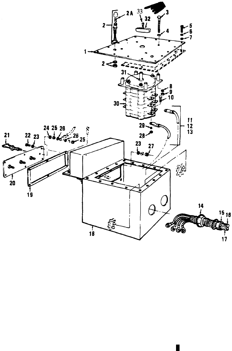
TM 5-6115-365-15
FIGURE 4-9. LEGEND TO PARTS
ITEM FUNCT ITEM
NO. GROUP NAME
14206 COVER
24206 LIGHT-WIRE
2A 4206 BULB
34206 SCREW
44206 PACKING
54206 SCREW
64206 WASHER
74206 WASHER
84206 WASHER
94206 NUT
10 4206 SCREW
ITEM FUNCT ITEM
NO. GROUP NAME
11 4206 LEAD
12 4206 LEAD
13 4206 LEAD
14 4206 PACKING
15 4206 STUFFING
16 4206 CABLE
17 4206 CABLE
18 4206 BOX
19 4206 GASKET
20 4206 TERMINAL BOARD
21 4206 TERMINAL LOAD
ITEM FUNCT ITEM
NO. GROUP NAME
22 4206 SCREW
23 4206 WASHER
24 4206 WAS HER
25 4206 NUT
26 4206 WASHER
27 4206 NUT
28 4206 NUT
29 4206 WAS HER
30 4206 SWITCH
31 4206 PACKING
32 4206 KNOB
33 4206 SCREW,
MACHINE
PAN HAND
Figure 4-9. Distribution box.
4-26 Change 11

(1) (2) (3) (4) (5) (6) (7)
FEDERAL DESCRIPTION UNIT QTY 15-DAY ORGANIZATIONAL ILLUS-
SMR STOCK OF INC MAINTENANCE ALW RATION
CODE NUMBER USABLE MEAS IN (a) (b) (c) (d) (a) (b)
ON UNIT FIG ITEM
REF NUMBER & MFR CODE CODE 1-5 6-20 21-50 51-100 NO. NO.
TM 5-6115-365-15
C3
PART III - PU-620/M
00001 REPAIR PARTS FOR ORGANIZATIONAL
MAINTENANCE
00002 GROUP 15 - FRAME
00005 1507 - LEVELING JACKS
X2 O5310-087-4652 NUT, SELF-LOCKING: 3/8-16 UNC EA 34- 42
00006 MS51922-17 (96906) 10
X2 O5305-269-3213 SCREW, CAP, HEXAGON HEAD EA 34- 44
00007 3/8-16 X 1 1/4 IN. LG 10
MS90725-62 (96906)
O O 2590-318-6691 TRAILER LEG PROP ASSEMBLY EA 1****4- 41
00008 13214E1206 (97403) 10
12 0 5310-809-4061 WASHER, FLAT: 3/8 IN. BSC SIZE EA 64- 43
00009 MS27183-15 (96906) 10
00010 GROUP 18 – BODY
00011 1810 - CARGO BODY
X2 O5310-087-4652 NUT, SELF-LOCKING: 3/8-16 UNC EA 34 4- 3
00013 MS51922-17 (96906) 10
X2 O5305-269-3213 SCREW, CAP, HEXAGON HEAD: EA 34 4- 5
00014 3/8-16 X 1 1/4 IN. LG 10
MS90725-62 (96906)
X2 O5310-809-4061 WASHER, FLAT: 3/8 in. BSC SIZE EA 68 4- 4
00016 MS27183-15 (96906) 10
00017 GROUP 22 - BODY ACCESSORY ITEMS
00018 2201 - CANVAS ITEMS
P O R 2540-926-0993 TARPAULIN EA 1****4- 29
00019 13214E1219 (97403) 11
X2 O5340-057-6956 BUCKLE, SPRING ACTION EA 8
00020 MS51929-2 (96906)
X2 OCHAPE ASSEMBLY EA 12
00021 13214E1392 (97403)
X2 O5340-078-7029 CLIP, END, STRAP EA 20
00022 MS51926-3 (96906)
X2 ODEE RING EA 14
00023 MS51925-8 (96906)
X2 OTEE HOOK EA 22
00024 13214E1497 (97403)
00025 2202 - ACCESSORY ITEMS
O O 2910-066-1235 ADAPTER ASSEMBLY, FUEL DRUM EA 2****4- 6
00026 13211E7541 (97403) 11
X2 OBOW, TRAILER TARPAULIN EA 44- 30
00027 13214E1218 (97403) 11
X2 O2510-706-4504 BRACKET ASSEMBLY: LIQUID CONTAINER, EA 64- 45
00028 5 GALLON 10
MS53052 (96906)
X2 O5340-999-6277 BRACKET ASSEMBLY, SLEDGE HAMMER EA 14- 14
00029 13214E1214 (97403) 11
4-27
(1) (2) (3) (4) (5) (6) (7)
FEDERAL DESCRIPTION UNIT QTY 15-DAY ORGANIZATIONAL ILLUS-
SMR STOCK OF INC MAINTENANCE ALW RATION
CODE NUMBER USABLE MEAS IN (a) (b) (c) (d) (a) (b)
ON UNIT FIG ITEM
REF NUMBER & MFR CODE CODE 1-5 6-20 21-50 51-100 NO. NO.
TM 5-6115-365-15
C3
X2 O7240-222-3088 CAN, GASOLINE: MILITARY, 5 GALLON EA 64- 47
00030 MILC1283 (81349) 10
X2 O2590-932-7298 CLAMP, GROUND ROD EA 44- 10
00031 13212E3617-1 (97403) 11
X2 O5340-914-2578 CLIP, SPRING, SLEDGE HAMMER EA 14- 18
00032 13214E1213-1 (97403) 11
X2 O7240-920-5327 HOLDER, FUEL DRUM ADAPTER EA 24- 2
00033 31213E3553-1 (97403) 11
X2 O5310-080-8495 NUT, PLAIN, WING: 1/4-20 UNC, 2B EA 24- 51
00034 MS35425-39 (96906) 10
X2 O5310-088-1251 NUT, SELF-LOCKING, HEXAGON: EA 84- 23
00035 1/4-20 UNC 11
MS51922-1 (96906)
X2 O5310-088-1251 NUT, SELF-LOCKING, HEXAGON: EA 44- 22
00036 1/4-20 UNC 11
MS51922-1 (96906)
X2 O5310-087-4652 NUT, SELF-LOCKING: 3/8-16 UNC EA 24 4- 46
00037 MS51922-17 (96906) 10
X2 O5310-984-3806 NUT, SELF-LOCKING: 5/16-18 UNC EA 44- 3
00038 MS51922-9 (96906) 11
X2 O5310-088-1251 NUT, SELF-LOCKING HEXAGON: 1/4-20 UNC EA 84- 7
00039 MS51922-1 (96906) 11
X2 O5310-088-1251 NUT, SELF-LOCKING: 1/4-20 UNC EA 24- 11
00040 MS51922-1 (96906) 11
X2 O5310-088-1251 NUT, SELF-LOCKING: 1/4-20 UNC EA 14- 15
00041 MS51922-1 (96906) 11
X2 OPLATE, FRONT, SHIELD EA 44- 50
00042 13214E1217-1 (97403) 10
X2 O9905-202-3639 REFLECTOR, INDICATING, AMBER EA 24- 26
00043 MS35387-2 (96906) 11
X2 O9905-205-2795 REFLECTOR, INDICATING CLEARANCE, RED EA 44- 22
00044 MS35387-1 (96906) 11
X2 O5305-068-0501 SCREW, CAP, HEXAGON: EA 84- 21
00045 1/4-20 X 5/8 IN. LG 11
MS90725-5 (96906)
X2 O5305-068-0501 SCREW, CAP, HEXAGON HEAD: EA 44- 25
00046 1/4-20 X 5/8 in. LG 11
MS90725-5 (96906)
X2 O5305-269-3211 SCREW, CAP, HEXAGON HEAD: EA 24 4- 48
00047 3/8-16 X 1 IN. LG 10
MS90725-60 (96906)
X2 O5305-071-2237 SCREW, CAP, HEXAGON HEAD: EA 24- 54
00048 1/4-20 X 2 IN. 10
MS90725-14 (96906)
12 0 5306-225-8497 SCREW, CAP, HEXAGON HEAD: 5/16-18 X 3/4 IN. LG EA 44- 5
00049 MS90725-32 (96906) 11
X2 O5305-068-0501 SCREW, CAP, HEXAGON HEAD: EA 24- 13
00050 1/4-20 X 5/8 IN. LG 11
MS90725-5 (96906)
X2 O5305-068-0501 SCREW, CAP, HEXAGON HEAD: EA 14- 17
00051 1/4-20 X 5/8 IN. LG 11
MS90725-5 (96906)
X2 O5305-958-5246 SCREW, MACHINE: 1/4-20 X 3/4 IN. LG EA 84- 9
00052 MS35190-289 (96906) 11
X2 O5310-809-4058 WASHER, FLAT: 1/4 IN. BSC EA 16 4- 20
00053 MS27183-10 (96906) 11
4-28
(1) (2) (3) (4) (5) (6) (7)
FEDERAL DESCRIPTION UNIT QTY 15-DAY ORGANIZATIONAL ILLUS-
SMR STOCK OF INC MAINTENANCE ALW RATION
CODE NUMBER USABLE MEAS IN (a) (b) (c) (d) (a) (b)
ON UNIT FIG ITEM
REF NUMBER & MFR CODE CODE 1-5 6-20 21-50 51-100 NO. NO.
TM 5-6115-365-15
X2 O5310-809-4058 WASHER, FLAT: 1/4 IN. BSC SIZE EA 84-11 24
00054 MS27183-10 (96906)
X2 O5310-809-4061 WASHER, FLAT: 3/8 IN. BSC SIZE EA 48 4-10 47
00055 MS27183-15 (96906)
X2 O5310-809-4058 WASHER, FLAT: 1/4 IN. BSC SIZE EA 44-10 53
00056 MS27183-10 (96906)
X2 O5310-081-4219 WASHER, FLAT: 5/16 IN. BSC SIZE EA 84-11 4
00057 MS27183-12 (96906)
X2 O5310-609-4058 WASHER, FLAT ROUND, 1/4 IN. BSC SIZE EA 84-11 8
00058 MS27183-10 (96906)
X2 O5310-809-4058 WASHER, FLAT: 1/4 IN. BSC SIZE EA 44-11 12
00059 MS27183-10 (96906)
X2 O5310-809-4058 WASHER, FLAT: 1/4 IN. BSC SIZE EA 24-11 16
00060 MS27183 10 (96906)
X2 O5310-042-6758 WASHER, LOCK: 1/4 IN. SCREW SIZE EA 24-10 52
00061 MS35338-82 (96906)
00062 2210-DATA PLATES
X2 OPLATE, IDENTIFICATION: GROUND TERMINAL EA 14-10 55
00063 13205E4918 (97403)
X2 OPLATE, IDENTIFICATION: PU620/M EA 14-11 28
00064 13205E4916-4 (97403)
00065 GROUP 29-AUXILIARY GENERATOR AND ENGINE
00072 2941-ENGINE EXHAUST
X2 O2990-01-015-2910 EXHAUST, TUBE EA 14-10 11
00073 13219E3662 (97403)
X2 O2990-01-415-2911 EXHAUST, TUBE EA 14-10 15
00074 13219E3661 (97403)
X2 O4720-00-156-9932 HOSE, CL, SCNPSNA TY2 1.75 ID x 28.00 PLUS OR MINUS .25 L EA 14-10 12
00074A WW-H-1053 (81348)
X2 O5310-088-1251 NUT, SELF-LOCKING EA 24-10 12
00075 MS51922-1 (96906)
X2 O5305-225-3839 SCREW, CAP, HEXAGON HEAD: 1/4-20 x 1 IN. LG EA 24-10 14
00076 MS90725-8 (96906)
X2 O5310-809-4058 WASHER, FLAT: 1/4 IN. BSC SIZE EA 44-10 13
00077 MS27183-10 (96906)
00078 GROUP 42-ELECTRICAL EQUIPMENT
00079 4202-ELECTRICAL CONTROLS
X2 O5310-087-4652 NUT, SELF-LOCKING, HEXAGON: 3/8-16 THD SIZE EA 4
00098
X2 OPLATE, INFORMATION: WIRING DIAGRAM EA 1
00102 13212E3587(97403)
X2 O5305-989-7434 SCREW, MACHINE: PAN HEAD, 10-32 x 1/2 IN. LG EA 16 4-9 5
00105
X2 O5310-809-8546 WASHER, FLAT: ROUND, NO. 10 EA 16 4-9 7
00114
X2 O5310-045-3296 WASHER, LOCK: HELICAL SPRING, NO. 10 EA 16 4-9 6
00118
X2 O5305-269-3211 SCREW, CAP, HEXAGON HEAD: 3/8-16 x 1 IN. LG EA 4
00122
Change 9 4-29

(1) (2) (3) (4) (5) (6) (7)
FEDERAL DESCRIPTION UNIT QTY 15-DAY ORGANIZATIONAL ILLUS-
SMR STOCK OF INC MAINTENANCE ALW RATION
CODE NUMBER USABLE MEAS IN (a) (b) (c) (d) (a) (b)
ON UNIT FIG ITEM
REF NUMBER & MFR CODE CODE 1-5 6-20 21-50 51-100 NO. NO.
TM 5-6115-365-15
C3
X2 O5310-809-4061 WASHER, FLAT: ROUND, 3/8 IN. EA 8
00124
00125 4216 - MISCELLANEOUS WIRING AND FITTINGS
X2 OCLAMP, CABLE, DOUBLE EA 24- 28
00126 13212E3591-4 (97403) 10
X2 OCLAMP, CABLE, SINGLE EA 14- 24
00127 13212E3612 (97403) 10
X2 O5340-526-2559 CLAMP, CUSHIONED: 1/8 IN. ID EA 24- 33
00128 MS21919-2 (96906) 10
X2 O5310-012-0361 NUT, PLAIN, HEXAGON: 10-24 UNC 2B EA 24- 29
00129 MS35649-102 (96906) 10
X2 ONUT, PLAIN, HEXAGON: 3/8-16 UNC 2B EA 14- 39
00130 FFN836TYPE2 (81348) 10
X2 ONUT, PLAIN, HEXAGON: 3/8-16 UNC 2B EA 14- 56
00131 FFN836TYFE2 (813348) 10
X2 ONUT, PLAIN, HEXAGON: JAM, 3/8-16 UNC 2B EA 24- 37
00132 FFN836TYPE2 (8 348) 10
X2 O5310-543-4717 NUT, PLAIN, WING: BRASS, 3/8-16 THD SIZE EA 14- 40
00133 MS35425-28 (96906) 10
X2 O5310-088-1251 NUT, SELF-LOCKING HEXAGON: 1/4-20 UNC EA 2 4 21
00134 MS51922-1 (96906) 10
X2 O5310-088-1251 NUT, SELF-LOCKING, HEXAGON: EA 44- 25
00135 1/4-20 UNC 10
MS51922-1 (96906)
X2 O5305-225-3840 SCREW, CAP, HEXAGON HEAD EA 24- 23
00136 1/4-20 Y 7/8 IN. LG 10
MS90725-7 (96906)
X2 O5305-225-3840 SCREW, CAP, HEXAGON HEAD:1/4-20 X 7/8 IN. LG EA 44- 27
00137 MS90725-7 (96906) 10
X2 O5305-543-4718 SCREW, CAP, HEXAGON HEAD: EA 14- 58
00138 3/8-16 3/4 IN. LG 10
MS35309-358 (96906)
X2 O5305-984-6211 SCREW, MACHINE: PAN HEAD, EA 24- 32
00139 10-24 X 5/8 IN. LG 10
MS35206-264 (96906)
X2 O5307-722-9437 STUD, GROUNDING EA 14- 35
00140 13214E1223 (97403) 10
X2 O5940-688-6010 TERMINAL, LUG: NO. 6 WIRE, EA 34- 59
00141 3/8 IN. STUD 10
MS20659-10 (96906)
X2 O5310-913-9776 WASHER, LOCK: FLAT EA 24- 36
00142 3/8 IN. SIZE 10
MS35335-91 (96906)
X2 O5310-913-9776 WASHER, LOCK: FLAT EA 14- 57
00143 3/8 IN. SIZE 10
MS35335-91 (96906)
X2 O5310-187-2413 WASHER, FLAT: ELECTRICAL, BRASS, 3/8 IN. EA 44- 38
00144 AN961-616T (88044) 10
X2 O5310-809-4058 WASHER, FLAT: 1/4 IN. BSC SIZE EA 44- 22
00145 MS27183-10 (96906) 10
X2 O5310-809-4058 WASHER, FLAT: 1/4 IN. BSC SIZE EA 84- 26
00146 MS27183-10 (96906) 10
X2 O5310-809-8546 WASHER, FLAT: NO 10 BSC SIZE EA 44- 31
00147 MS27183-8 (96906) 10
X2 O5310-045-3296 WASHER, LOCK: NO. 10 SIZE EA 24- 30
00148 MS35338-43 (96906) 10
4-30
(1) (2) (3) (4) (5) (6) (7) (8) (9) (10)
DESCRIPTION 1-YR
DEPOT
QTY 30-DAY DS MAINT 30-DAY GS MAINT ALW
PER MAINT
ALW ILLUS-
TRATION
FEDERAL USABLE UNIT INC ALLOWANCE ALLOWANCE 100 PER (a) (b)
SMR
CODE STOCK
NUMBER
ON
REF NUMBER & MFR CODE CODE OF
MEAS IN
UNIT (a)
1-20 (b)
21-50
(c)
51-100
(a)
1-20 (b)
21-50
(c)
51-100
EQUIP
CNTGCY 100
EQUIP FIG.
NO. ITEM
NO.
TM 5-6115-365-15
PART IV- PU620/M
00001 REPAIR PARTS FOR DS, GS AND
DEPOT MAINTENANCE
00002 GROUP 15 - FRAME
00003 1501 - FRAME ASSEMBLY
X2D R2330-898-6780 CHASSIS TRAILER: M116A1 EA 14- 1
00004 13214E1201 (97403) 10
00005 1507 - LEVELING JACKS
X2 O5310-087-4652 NUT, SELF-LOCKING: 3/8-16 UNC EA 34- 42
00006 MS51922-17 (96906) 10
X2 O5305-269-3213 SCREW, CAP, HEXAGON HEAD: EA 34- 44
00007 3/8-16 X 1 1/4 IN. LG 10
MS90725-62 (96906)
O O 2590-00-420-8929 TRAILER LEG PROP ASSEMBLY EA 1* * 2* * 2 10 10 4- 41
00008 13214E1206 (97403) 10
X2 O5310-809-4061 WASHER, FLAT: 3/8 IN. BSC SIZE EA 64- 43
00009 MS27183015 (96906) 10
00010 GROUP 18 - BODY
00011 1810-CARGO BODY
X2D RBODY, TRAILER EA 14- 2
00012 13214E1202 10
X2 O5310-087-4652 NUT, SELF-LOCKING: 3/8-16 UNC EA 34 4- 3
00013 MS51922-17 (96906) 10
X2 O5305-269-3213 SCREW, CAP, HEXAGON HEAD: EA 34 4- 5
00014 3/8-16 X 1 1/4 IN. LG 10
MS90725-62 (96906)
X2 DSHIM (AS REQUIRED) EA 4- 1
00015 13214E1494(97403) 11
X2 O5310-809-4061 WASHER, FLAT: 3/8 IN. BSC SIZE EA 68 4- 4
00016 MS27183-15 (96906)
10
00017 GROUP 22 - BODY ACCESSORY ITEMS
00018 2201 - CANVAS ITEMS
P O R 2540-926-0993 TARPAULIN EA 1* * 2* * 2 10 10 4- 29
00019 13214E1219 11
X2 O5340-057-6956 BUCKLE, SPRING ACTION EA 8
00020 MS51929-2 (96906)
X2 OCHAPE ASSEMBLY EA 12
00021 13214E192 (97403)
X2 O5340-078-7029 CLIP, END, STRAP EA 20
00022 MS51027-30 (96906)
X2 ODEE RING EA 14
00023 MS51925-8 (96906)
X2 OTEE HOOK EA 22
00024 13214E1497 (97403)
00025 22-2 - ACCESSORY ITEMS
O O 2910-066-1235 ADAPTER ASSEMBLY, FUEL DRUM EA 2* * 2* * 2 10 10 4- 6
00026 13211E7541 (97403) 11
Change 10 4-31
(1) (2) (3) (4) (5) (6) (7) (8) (9) (10)
DESCRIPTION 1-YR
DEPOT
QTY 30-DAY DS MAINT 30-DAY GS MAINT ALW
PER
MAINT
ALW ILLUS-
TRATION
FEDERAL USABLE
UNIT
INC ALLOWANCE ALLOWANCE 100 PER (a) (b)
SMR
CODE STOCK
NUMBER
ON
REF NUMBER & MFR CODE CODE OF
MEAS IN
UNIT (a)
1-20 (b)
21-50 (c)
51-100 (a)
1-20 (b)
21-50 (c)
51-100
EQUIP
CNTGCY 100
EQUIP
FIG.
NO.
ITEM
NO.
TM 5-6115-365-15
C3
X2 OBOW, TRAILER TARPAULIN EA 44- 30
00027 13214E1218 (97403) 11
X2 O2510-706-4504 BRACKET ASSEMBLY LIQUID CONTAINER, EA 64- 45
00028 5 GALLON 10
MS53052 (96906)
X2 O5340-999-6277 BRACKET ASSEMBLY, SLEDGE HAMMER EA 14- 14
00029 13214E1214 (97403) 11
X2 O7240-222-3088 CAN, GASOLINE: MILITARY, 5 GALLON EA 64- 47
00030 MILC1283 (81349) 10
X2 O2590-932-7298 CLAMP, GROUND ROD EA 44- 10
00031 13212E3617-1 (97403) 11
X2 O5340-914-2578 CLIP, SPRING, SLEDGE HAMMER EA 14- 18
00032 13214E1213-1 (97403) 11
X2 O7240-920-5327 HOLDER, FUEL DRUM ADAPTER EA 24- 2
00033 13212E3553-1 (97403) 11
X2 O5310-080-8495 NUT, PLAIN, WING: 1/4-20 UNC, 2B EA 24- 51
00034 MS35425-39 (96906) 10
X2 O5310-088-1251 NUT, SELF-LOCKING, HEXAGON: EA 84- 23
00035 1/4-20 UNC 11
MS51922-1 (96906)
X2 O5310-088-1251 NUT, SELF-LOCKING, HEXAGON: EA 44- 22
00036 1/4-20 UNC 11
MS51922-1 (96906)
12 0 5310-087-4652 NUT, SELF-LOCKING: 3/8-16 UNC EA 24 4- 46
00037 MS51922-17 (96906) 10
12 0 5310-984-3806 NUT, SELF-LOCKING: 5/16-18 UNC EA 44- 3
00038 MS51922-9 (96906) 11
X2 O5310-088-1251 NUT, SELF-LOCKING, HEXAGON: EA 84- 7
00039 1/4-20 UNC 11
MS51922-1 (96906)
X2 O5310-088-1251 NUT, SELF-LOCKING: 1/4-20 UNC EA 24- 11
00040 MS51922-1 (96906) 11
X2 O5310-088-1251 NUT, SELF-LOCKING: 1/4-20 UNC EA 14- 15
00041 MS51922-1 (96906) 11
X2 OPLATE, FRONT, SHIELD EA 44- 50
00042 13214E1217-1 (97403) 10
X2 O9905-202-3639 REFLECTOR, INDICATING, AMBER EA 24- 26
00043 MS35387-2 (96906) 11
X2 O9905-205-2795 REFLECTOR, INDICATING CLEARANCE, RED EA 44- 22
00044 MS35387-1 (96906) 11
X2 O5305-068-0501 SCREW, CAP, HEXAGON HEAD: EA 84- 21
00045 1/4-20 X 5/8 IN. LG 11
MS90725-5 (96906)
X2 O5305-068-0501 SCREW, CAP, HEXAGON HEAD: EA 44- 25
00046 1/4-20 X 5/8 IN. LG 11
MS90725-5 (96906)
X2 O5305-269-3211 SCREW, CAP, HEXAGON HEAD: EA 24 4- 48
00047 3/8-16 X 1 IN. LG 10
MS90725-60 (96906)
12 0 5305-071-2237 SCREW, CAP, HEXAGON HEAD: EA 24- 54
00048 1/4-20 1 2 IN. LG 10
MS90725-14 (96906)
X2 O5306-225-8497 SCREW, CAP, HEXAGON HEAD: EA 44- 5
00049 5/16-18 X 3/4 in. lg 11
MS90725-32 (96906)
X2 O5305-068-0501 SCREW, CAP, HEXAGON HEAD: EA 24- 13
00050 1/4-20 X 5/8 IN. LG 11
MS90725-5 (96906)
4-32
(1) (2) (3) (4) (5) (6) (7) (8) (9) (10)
DESCRIPTION 1-YR
DEPOT
QTY 30-DAY DS MAINT 30-DAY GS MAINT ALW
PER MAINT
ALW ILLUS-
TRATION
FEDERAL USABLE UNIT INC ALLOWANCE ALLOWANCE 100 PER (a) (b)
SMR
CODE STOCK
NUMBER
ON
REF NUMBER & MFR CODE CODE OF
MEAS IN
UNIT (a)
1-20 (b)
21-50
(c)
51-100
(a)
1-20 (b)
21-50
(c)
51-100
EQUIP
CNTGY 100
EQUIP FIG.
NO. ITEM
NO.
TM 5-6115-365-15
X2 O5305-068-0501 SCREW, CAP, HEXAGON HEAD: EA 14- 17
00051 1/4-20 x 5/8 IN. LG 11
MS90725-5 (96906)
X2 O5305-958-5246 SCREW, MACHINE: 1/4-20 x 3/4 IN. LG EA 84- 9
00052 MS35190-289 (96906) 11
X2 O5310-8094058 WASHER, FLAT: 1/4 IN. BSC EA 16 4- 20
00053 MS27183-10 (96906) 11
X2 O5310-809-4058 WASHER, FLAT: 1(4 IN. BSC SIZE EA 84- 24
00054 MS27183-10 (96906) 11
X2 O5310-809-4061 WASHER, FLAT: 3/8 IN. BSC SIZE EA 48 4- 47
00055 MS27183-15 (96906) 10
X2 O5310-809-4058 WASHER, FLAT: 1(4 IN. BSC SIZE EA 44- 53
00056 MS27183-10 (96906) 10
X2 O5310-081-4219 WASHER, FLAT: 5/16 IN. BSC SIZE EA 84- 4
00057 MS27183-12 (96906) 11
X2 O5310-8094058 WASHER, FLAT: ROUND, 1/4 IN. BSC SIZE EA 84- 8
00058 MS27183-10 (96906) 11
X2 O5310-809-4058 WASHER, FLAT: 1/4 IN. BSC SIZE EA 44- 12
00059 MS27183-10 (96906) 11
X2 O5310-809-4058 WASHER, FLAT: 1/4 IN. BSC SIZE EA 24- 16
00060 MS2713-10 (96906) 11
X2 O5310-042-6758 WASHER, LOCK: 1/4 IN. SIZE EA 24- 52
00061 MS35338-82 (96906) 10
00062 2210--DATA PLATES
X2 OPLATE, IDENTIFICATION: GROUND TERMINAL EA 14- 55
00063 13295E4918 (97403) 10
XS 0PLATE, IDENTIFICATION: PU620/M EA 1 4-28
00064 13205E4916-4 (97403) 11
00065 GROUP 29-AUXILIARY GENERATOR AND ENGINE
00066 2901-GENERATOR AND ENGINE ASSEMBLY
X2F R6115-017-8240 GENERATOR SET: SF 5.0 MD EA 24- 6
00067 MILG52279 (81349) 10
X2F5310-225-6993 NUT, SELF-LOCKING: 1/2-13 UNC EA 84- 7
00068 MS51922-33 (96906) 10
X2 F5305-071-1769 SCREW, CAP, HEXAGON HEAD: EA 84- 10
00069 1/2-13 x 2 IN. LG 10
MS90725-115 (96906)
X2 F5310-520-3091 WASHER, BEVELED EA 84- 9
00070 13206E4482-2 (97403) 10
X2 F5310-809-5998 WASHER, FLAT, 1/2 IN. ID x 1-1/2 IN. OD EA 84- 8
00071 MS27183-18 (96906) 10
2941-ENGINE EXHAUST
X2 O6115-947-3335 EXH AUST, TUBE EA 14- 11
00073 13214E1487 (97403) 10
X2 O6115-947-3331 EXHAUST, TUBE EA 14- 15
00074 13214E1486 (97403) 10
X2 O5310-088-1251 NUT, SELF-LOCKING EA 24- 12
00075 MS51922-1 (96906) 10
Change 9 4-33

(1) (2) (3) (4) (5) (6) (7) (8) (9) (10)
DESCRIPTION 1-YR
DEPOT
QTY
30-DAY DS MAINT
30-DAY GS MAINT
ALW
PER MAINT
ALW ILLUS-
TRATION
FEDERAL USABLE UNIT INC ALLOWANCE ALLOWANCE 100 PER (a) (b)
SMR
CODE STOCK
NUMBER
ON
REF NUMBER & MFR CODE CODE OF
MEAS
IN
UNIT (a)
1-20 (b)
21-50 (c)
51-100 (a)
1-20 (b)
21-50 (c)
51-100
EQUIP
CNTGY
100
EQUIP FIG.
NO. ITEM
NO.
TM 5-6115-365-15
C3
X2 O5305-225-3839 SCREW, CAP, HEXAGON HEAD: EA 24- 14
00076 1/4-20 X 1 IN. LG 10
MS90725-8 (96906)
X2 O5310-809-4058 WASHER, FLAT: 1/4 IN. BSC SIZE EA 44- 13
00077 MS27183-10 (96906) 10
00078 GROUP 42 - ELECTRICAL EQUIPMENT
00079 4202 - ELECTRICAL CONTROLS
PF6110-913-9275 DISTRIBUTION BOX EA 1******2 2 4- 20
00080 13212E3601 (97403) 10
X2 F6115-104-4550 BOX EA 14- 18
00081 13212E3602 (97403) 9
X2 F6115-948-7169 CABLE EA 14- 16
00082 13212E3607 (97403) 9
X2 F6115-948-7170 CABLE EA 14- 17
00083 13212E3608 (97403) 9
X2 FCABLE EA 2
00084 13216E7479 (97403)
X2 FCOVER EA 14- 1
00085 13212E3603 (97403) 9
X2 FGASKET EA 14- 19
00086 13212E3610 (97403) 9
MFLEAD, ELECTRICAL EA 14- 11
00087 13212E609-1 (97403) 9
MANUFACTURE FROM:
PF6145-284-0656 WIRE, ELECTRICAL: 600V FT
00088 AIRCRAFT, A16, MIL-3-5-5086
MFLEAD, ELECTRICAL EA 14- 13
00089 13212E3609-3 (97403) 9
MANUFACTURE FROM:
PF6145-284-0656 WIRE, ELECTRICAL: 600V FT
00090 AIRCRAFT, AN6, MIL-W-5086
MFLEAD, ELECTRICAL EA 14- 12
00091 13212E3609-2 (97403) 9
MANUFACTURE FROM:
PF6145-284-0656 WIRE, ELECTRICAL: 600V FT
00092 AIRCRAFT, AN6, MIL-W-5086
PFLEAD, ELECTRICAL EA 1
00093 13216Z7476 (97403)
X2 FLIGHT AND WIRE: 12 IN. LG EA 24- 2
00094 13212E3581-1 (97403) 9
X2 FNUT, PLAIN, HEXAGON: JAM, EA 84- 25
00095 1/4-20 TBD SIZE 9
MS16203-37 (96906)
X2 F5310-924-4218 NUT, PLAIN, HEXAGON: EA 94- 28
00096 1/4-28 TED SIZE 9
X2 F5310-934-9758 NUT, PLAIN, HEXAGON: MACHINE SCREW EA 64- 27
00097 9
X2 O5310-087-4652 NUT, SELF-LOCKING, HEXAGON: EA 4
00098 3/8-16 THD SIZE
X2 F5330-802-5905 PACKING, PREFORMED: O RING EA 24- 14
00099 MS28775-132 (969069
X2 F5330-579-8108 PACKING, PREFORMED: O RING EA 14- 31
00100 M28775-111 (96906) 9
X2 F5330-684-3420 PACKING, PREFORMED: O RING EA 44- 4
00101 MS28775-013 (96906) 9
4-34
(1) (2) (3) (4) (5) (6) (7) (8) (9) (10)
DESCRIPTION 1-YR
DEPOT
QTY 30-DAY DS MAINT 30-DAY GS MAINT ALW
PER MAINT
ALW ILLUS-
TRATION
FEDERAL USABLE UNIT INC ALLOWANCE ALLOWANCE 100 PER (a) (b)
SMR
CODE STOCK
NUMBER
ON
REF NUMBER & MFR CODE CODE OF
MEAS IN
UNIT (a)
1-20 (b)
21-50
(c)
51-100
(a)
1-20 (b)
21-50
(c)
51-100
EQUIP
CNTGY 100
EQUIP FIG.
NO. ITEM
NO.
TM 5-6115-365-15
X2 OPLATE, INFORMATION: WIRING DIAGRAM EA 1
00102 13212E3587 (97403)
X2 F5305-984-6214 SCREW, MACHINE: PAN HEAD EA 64- 22
00103 9
X2 FSCREW, MACHINE: PAN HEAD EA 94- 10
00104 1/4-28 x 7/16 IN. LG MS35215-68 (96906) 9
X2 O5305-989-7434 SCREW, MACHINE: PAN HEAD, EA 16 4- 5
00105 10-32 x 1/2 IN. LG 9
X2 F5305-984-5695 SCREW, MACHINE PAN HEAD, EA 44- 3
00106 318-16 x 2 IN. LG 9
X2 FSTUFFING TUBE EA 24- 15
00107 13212E3583-20 (97403) 9
PF5930-829-3243 SWITCH, ROTARY: 60 AMP EA 1******2 2 4- 30
00108 13205E5023(97403) 9
X2 FTERMINAL, BOARD EA 14- 20
00109 13212E3606(97403) 9
X2 F5940-904-9634 TERMINAL, LOAD EA 44- 21
00110 13208E5820-6 (97403) 9
X2 FTERMINAL, LUG: SIZE 6 STUD, 1/4 IN. EA
00111 (AS REQUIRED)
MS25036-20 (96906)
X2 F5940-660-3631 TERMINAL, LUG: 18-22 STUD, 1/4 IN. EA 4
00112
X2 F5310-809-8546 WASHER, FLAT ROUND, NO. 10 EA 12 4- 23
00113 9
X2 O5310-809-8546 WASHER, FLAT' ROUND, NO. 10 EA 16 4- 7
00114 9
X2 F5310-080-6004 WASHER, FLAT: ROUND, 3/8 IN. EA 84- 8
00115 9
X2 FWASHER, LOCK: FLAT, EXTERNAL EA 94- 29
00116 TOOTH, 1/41 IN. 9
MS35335-89 (96906)
X2 F5310-045-3296 WASHER, LOCK: HELICAL SPRING, EA 6
00117 NO. 10
X2 O5310-045-3296 WASHER. LOCK: HELICAL SPRING, EA 16 4- 6
00118 NO. 10 9
X2 F5310-184-8970 WASHER, LOCK: HELICAL SPRING EA 84- 24
00119 9
X2 F5310-022-8834 WASHER, LOCK: FLAT, INTERNAL EA 44- 26
00120 TOOTH, 1/4 IN. 9
X2 F5310-087-4652 NUT, SELF-LOCKING, HEXAGON: EA 44- 9
3/8-16 THD SIZE 9
X2 O5305-269-3211 SCREW, CAP, HEXAGON HEAD: EA 4
00122 3/8-16 x 1 IN. LG
X2 FSTRAP, CABLE ADJUSTER: 1-1/2 IN. EA 1
00123 MAXIMUM BINDING SIZE
MS17821-1-0 (96906)
X2 O5310-809-4061 WASHER, FLAT: ROUND, 3/8 IN. EA 8
00124
00125 4216-MISCELLANEOUS WIRING AND FITTINGS
X2 OCLAMP, CABLE, DOUBLE EA 24- 28
00126 13212E3591-4 (97403) 10
X2 OCLAMP, CABLE, SINGLE EA 14- 24
00127 13212E3612(97403) 10
Change 9 4-35

(1) (2) (3) (4) (5) (6) (7) (8) (9) (10)
DESCRIPTION 1-YR
DEPOT
QTY
30-DAY DS MAINT
30-DAY GS MAINT
ALW
PER MAINT
ALW ILLUS-
TRATION
FEDERAL USABLE UNIT INC ALLOWANCE ALLOWANCE 100 PER (a) (b)
SMR
CODE STOCK
NUMBER
ON
REF NUMBER & MFR CODE CODE OF
MEAS
IN
UNIT (a)
1-20 (b)
21-50 (c)
51-100 (a)
1-20 (b)
21-50 (c)
51-100
EQUIP
CNTGY
100
EQUIP FIG.
NO. ITEM
NO.
TM 5-6115-365-15
C3
X2 O5340-526-2559 CLAMP, CUSHIONED: EA 24- 33
00128 1/8 IN. ID 10
MS21919-2 (96906)
X2 O5310-012-0361 NUT, PLAIN, HEXAGON: No. EA 24- 29
00129 10-24 UNC 2B 10
MS35649-102 (96906)
X2 ONUT, PLAIN, HEXAGON: EA 14- 39
00130 3/8-16 UNC 2B 10
FFN836TYPE2 (81348)
X2 ONUT, PLAIN, HEXAGON: EA 14- 56
00131 3/8-16 UNC 2B 10
FFN836TYPE2 (81348)
X2 ONUT, PLAIN, HEXAGON: JAM, EA 24- 37
00132 3/8-16 UNC 2B 10
FFN836TYPE2 (81348)
X2 O5310-543-4717 NUT, PLAIN, WING: BRASS, EA 14- 40
00133 3/8-16 THD SIZE 10
MS35425-28 (96906)
X2 O5310-088-1251 NUT, SELF-LOCKING, HEXAGON: EA 24- 21
00134 1/4-20 UNC 10
MS51922-1 (96906)
X2 O5310-088-1251 NUT, SELF-LOCKING, HEXAGON: EA 44- 25
00135 1/4-20 UNC 10
MS51922-1 (96906)
X2 O5305-225-3840 SCREW, CAP, HEXAGON HEAD: EA 24- 23
00136 1/4-20 X 7/8 IN. LG 10
MS90725-7 (96906)
X2 O5305-225-3840 SCREW, CAP, HEXAGON READ: EA 44- 27
00137 1/4-20 X 7/8 IN. LG 10
MS90725-7 (96906)
X2 O5305-543-4718 SCREW, CAP, HEXAGON HEAD EA 14- 58
00138 3/8-16 3/4 IN. LG 10
MS35309-358 (96906)
X2 O5305-984-6211 SCREW, MACHINE: PAN HEAD, No. EA 24- 32
00139 10-24 X 5/8 IN. LG 10
MS35206-264 (96906)
X2 O5307-722-9437 STUD, GROUNDING EA 14- 35
00140 13214E1223 (97403) 10
X2 O5940-688-6010 TERMINAL, LUG: No. 6 WIRE, EA 34- 59
00141 3/8 IN. STUD 10
MS20659-10 (96906)
X2 O5310-913-9776 WASHER, LOCK: FLAT EA 2 4-36
00142 3/8 IN. SIZE 10
MS35335-91 (96906)
X2 O5310-913-9776 WASHER, LOCK: FLAT EA 14- 57
00143 3/8 IN. SIZE 10
MS35335-91 (96906)
X2 O5310-187-2413 WASHER, FLAT: ELECTRICAL, BRASS, EA 44- 38
00144 3/8 IN. 10
AN961-616T (88044)
X2 O5310-809-4058 WASHER, FLAT: 1/4 IN. BSC SIZE EA 44- 22
00145 MS27183-10 10
X2 O5310-809-4058 WASHER, FLAT: 1/4 in. BSC SIZE EA 84- 26
00146 MS27183-10 (96906) 10
X2 O5310-809-8546 WASHER, FLAT: No. 10 BSC SIZE EA 44- 31
00147 MS27183-8 (96906) 10
X2 O5310-045-3296 WASHER, LOCK: EA 24- 30
00148 No. 10 SCREW SIZE 10
MS35338-43 (96906)
PF6145-395-8799 WIRE, ELECTRIC, UNINSULATED No. 6 AWG FT 15 ******* * 4- 60
00149 QQW343TYPERB 10
4-36
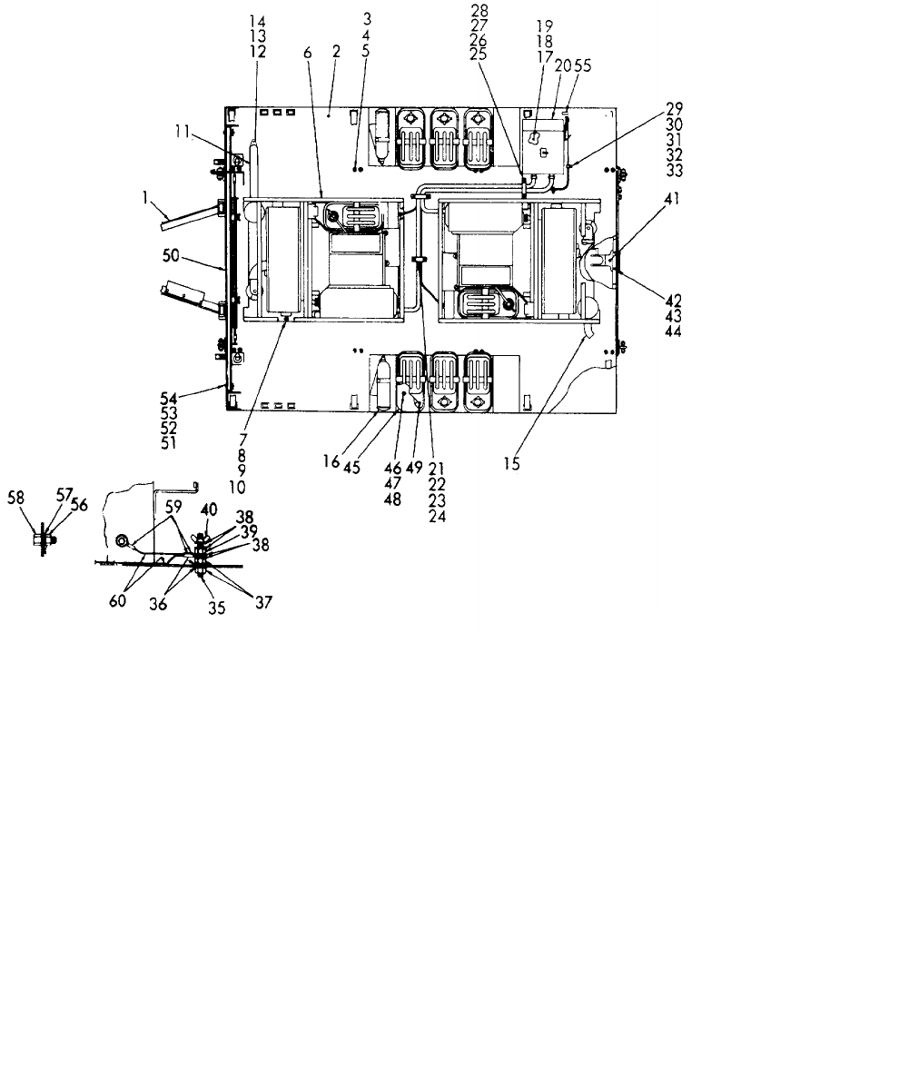
TM 5-6115-365-15
C3
Figure 4-10. PU-620/M Power unit.
ME 6115-365-15/4-10 C3
4-37
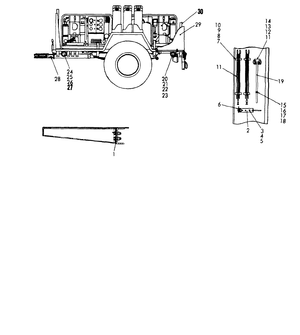
TM 5-6115-365-15
Figure 4-11. PU-620/M accessories.
ME 6115-365-15/4-11 C3
4-38

TM 5-6115-365-15
C1
CHAPTER 5
GENERATOR SETS PU-406/M and PU-402/M
Section I. DESCRIPTION AND DATA
5-1. Description
a. General. A 30-kw, 60-cycle, diesel engine
driven generator, capable of supplying 25-kw, 50 cycle
power, mounted on an M-200A1 trailer (modified),
comprise a self-contained mobile unit referred to as
Trailer-Mounted Generator Set, PU-406/M. Refer to
figures 5-1 and 5-2. A 15-kw, ,60 cycle, diesel engine-
driven generator, capable of supplying 12.5-kw, 50-cycle
power, mounted on a M-200A1 trailer, comprise a self-
contained mobile unit referred to as Trailer-Mounted
Generator Set, PU-402/M.
b. Function. PU-406/M is a mobile power plant
and may be used to supply power to any system
requiring a 30-kw, 60-cycle current PU-402/M is a mobile
power source capable of furnishing 15-kw, 60-cycle
current. Note. The only difference between the PU-
406/M and PU-402/M generator sets is in the output.
The sets are similar to each other in appearance.
d. Generator and Engine. For description and
further operation and maintenance information on the
PU-406/M generator and engine not covered in this
chapter, refer to TM 5-6115-321-15. For PU-402/M,
refer to applicable TM for generator set used. (See DA
PAM 310-4).
e. Trailer. For description and maintenance
information on the M-200A1 trailer, refer to
TM 9-230-205-14.
f. Lubrication. Refer to LO 9-2330-205-14 for
lubrication information required on the M-200A1 trailer.
5-2. Tabulated Data
Table 5-1 lists the components that comprise PU-406/M
and PU-402/M.
Table 5-1. PU-406/M and PU-402/M Components.
Fan Qty Nomenclature
2330-331-2307 1Trailer: M-200A1
6115-077-8600 1Generator set: 30 kw, DED
(PU-406/M)
6115-317-4919 1Generator set: 15 kw, DED
(PU-402/M)
7240-222-3088 2Can, gasoline, military
5-gallon
4210-555-8837 1Fire extinguisher
5975-878-3791 2Ground rod (w/attachments)
5120-251-4489 1Sledge hammer
5-1
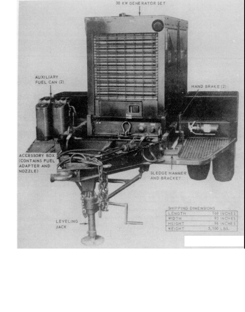
TM 5-6115-365-15
C1
Figure 5-1. PU-406M, left front, 3/4 view.
ME 6115-365-15/5-1 C1
5-2
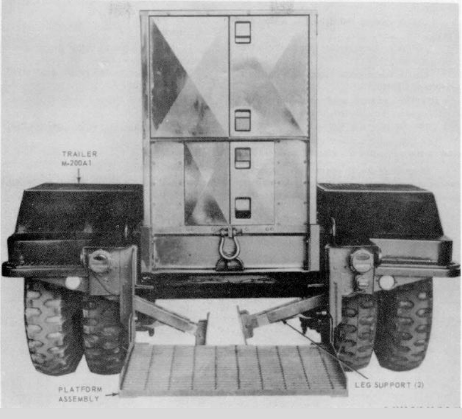
TM 5-6115-365-15
C1
ME 6115-365-15/5-2 C1
Figure 5-2. PU-406/M, rear view.
Section II. OPERATING INSTRUCTIONS
5-3. Setting-Up Instructions
a. Leveling.
(1) Locate the trailer on as level a surface as
possible in order for the generator set to operate
efficiently.(2) Set brakes and block wheels securely .to
prevent any movement. Operate the handbrakes at
weekly intervals to assure freedom of ,linkage.
(3) Pull leg supports down and adjust length
for firm contact with ground.
Warning
Wheels must be blocked, brakes set,
and leg supports down in support
position before operating the
equipment.
b. Grounding. Warning
Never operate the generator set until
it has been properly grounded.
Electrical defects in the load lines or
equipment can cause death by
electrocution when contact is made
with an ungrounded system.
(1) The generator set must be grounded prior
to operation. The ground may be any of
5-3
TM 5-6115-365-15
C3
three methods, depending on the location and the
terrain. (a) A ground rod driven to a depth of 8
feet. (b) An underground metallic water
piping system. (c) A metal plate (9 sq. ft.) buried at a
depth of 4 feet.
(2) The ground lead must be No. 6 AWG
copper wire bolted or clamped to the rod, plate, or piping
system. (3) Connect the other end of the ground lead
to the generator set ground stud.
Warning
Never operate the generator set in an
enclosed area unless the exhaust
gases are piped to the outside.
Inhalation of exhaust fumes will
result in serious illness or death.
5-4. Starting
a. Perform the pre-starting procedures described in
paragraph 5-3.
b. Start the generator set as instructed in
TM 5-6115-321-12.
5-5. Stopping
Stop the generator set as instructed in
TM 5-6115-321-12.
5-6. Operation
Operate the generator set as instructed in
TM 5-6115-321-12.
Section III. DIRECT AND GENERAL SUPPORT AND DEPOT
MAINTENANCE INSTRUCTIONS
5-7. Generator Set
a. Removal. Remove the generator set from the
trailer as illustrated in figure 5-3. b. Installation. Install the generator set as
illustrated in figure 5-3.
5-4
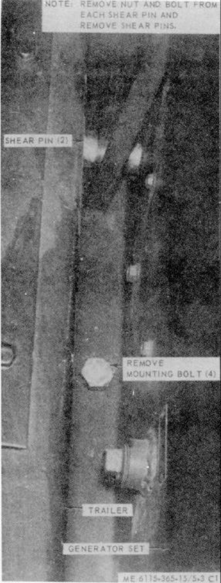
TM 5-6115-365-15
C1
Figure 5-3. Generator set, removal and installation.
5-5

(1) (2) (3) (4) (5) (6) (7)
FEDERAL DESCRIPTION UNIT QTY 15-DAY ORGANIZATIONAL ILLUS-
SMR STOCK OF INC MAINTENANCE ALW RATION
CODE NUMBER USABLE MEAS IN (a) (b) (c) (d) (a) (b)
ON UNIT FIG ITEM
REF NUMBER & MFG CODE CODE 1-5 6-20 21-50 51-100 NO. NO.
TM 5-6115-365-15
C1
PART I
REPAIR PARTS FOR ORGANIZATIONAL MAINTENANCE
00001 GROUP 15 - FRAME, TOWING ATTACHMENTS, AND DRAWBARS
00002 1501 - FRAME ASSEMBLY
X2 OBRACKET ASSEMBLY: liquid count, 5 gal EA 2
00003 MS53052-1 (96906)
X2 OBRACKET ASSEMBLY: sledge hammer EA 1
00004 13214E1214 (97403)
X2 OBRACKET FIRE EXTINGUISHER: 5 lb EA 1
00005 13214E1235 (97403)
X2 OCLIP SPRING EA 1
00006 13214E1213-1 (97403)
X2 ONUT, PLAIN, HEXAGON: jam, 3/8-16 n/mag EA 3
00007 MS16203-39 (96906)
X2 ONUT, PLAIN, WING: brass, 3/8-16 EA 1
00008 MS35425-28 (96906)
X2 ONUT, SELF-LOCKING, HEXAGON: 1/4-20 EA 1
00009 MS51922-1 (96906)
X2 ONUT, SELF-LOCKING, HEXAGON: 1/4-20 EA 2
00010 MS51922-1 (96906)
X2 ONUT, SELF-LOCKING, HEXAGON: 3/8-16 EA 4
00011 MS51922-17 (96906)
X2 ONUT, SELF-LOCKING, HEXAGON: 3/8-16 EA 8
00012 MS51922-17 (96906)
X2 ONUT, SELF-LOCKING, HEXAGON: 5/16-18 EA 2
00013 MS51922-9 (96906)
X2 OPIN, SHEAR EA 2
00014 13214E1254-1 (97403)
X2 OSCREW, CAP HEXAGON HEAD: 1/4-20 x 3/4, lg EA 2
00015 MS90725-6 (96906)
X2 OSCREW, CAP, HEXAGON HEAD: 1/6-20 x 3/4, lg EA 1
00016 MS90725-6 (96906)
X2 OSCREW, CAP, HEXAGON HEAD: 3/8-16 x 7/8, lg EA 8
00017 MS90725-59 (96906)
X2 OSCREW, CAP, HEXAGON HEAD: 5/16-18 x 2-1/4 EA 2
00018 MS90725-41 (96906)
X2 OSCREW, MACHINE, PAN HEAD: 3/8-16 x 1, lg EA 4
00019 MS35206-311 (96906)
X2 OSTUD, GROUND EA 1
00020 13214E1223 (97403)
X2 OWASHER, FLAT, ELECTRIC: brass, 3/8, size EA 4
00021 AN961-616T (88044)
X2 OWASHER, FLAT: round, 1/4 BSC, size EA 1
00022 MS27183-10 (96906)
X2 OWASHER, FLAT: round, 1/4 BSC, size EA 2
00023 MS27183-10 (96906)
X2 OWASHER, FLAT: round, 3/8 BSC, size EA 4
00024 MS27183-14 (96906)
X2 OWASHER, FLAT: round, 3/8 BSC, size EA 8
00025 MS27183-14 (96906)
X2 OWASHER, FLAT: round, 5/16 EA 2
00026 MS27183-13 196906)
5-6
(1) (2) (3) (4) (5) (6) (7)
FEDERAL DESCRIPTION UNIT QTY 15-DAY ORGANIZATIONAL ILLUS-
SMR STOCK OF INC MAINTENANCE ALW RATION
CODE NUMBER USABLE MEAS IN (a) (b) (c) (d) (a) (b)
ON UNIT FIG ITEM
REF NUMBER & MFG CODE CODE 1-5 6-20 21-50 51-100 NO. NO.
TM 5-6115-365-15
C1
X2 OWASHER, LOCK, FLAT: external tooth, 3/8 EA 2
00027 MS35335-91 (96906)
00028 GROUP 18 - BODY, CAB, HOOD AND HULL
00029 1808 - BOXES, CARRYING CASES
X2 OACCESSORY BOX EA 1
00030 13214E1256 (97403)
X2 ONUT, SELF-LOCKING, HEXAGON:5/16-18 EA 3
00031 MS51922-9 (96906)
X2 OSCREW, CAP, HEXAGON HEAD: 5/16-18 x 1, Ig EA 3
00032 MS90725-34 (96906)
X2 OWASHER, FLAT: round, 5/16, screw size EA 3
00033 MS27183-13 (96906)
00034 GROUP 22 - BODY CHASSIS OR HULL, AND ACCESSORY ITEMS
00035 2202 - ACCESSORY ITEM
PC2910-066-1235 ADAPTER ASSEMBLY: fuel drum EA 1****
00036 13211E7541 (97403)
O O 7240-222-3088 CAN, GASOLINE, MILITARY: 5 gal EA 2****
00037 MILC1283 (81349)
PC5120-203-4656 HAMMER HAND: double face EA 1****
00038 GGG14-86TYPEK (81348)
PC5975-878-3791 ROD, GROUND ASSEMBLY EA 2****
00039 MILR11461TYPE (81349)
X2 OSPOUT CAN: flexible EA 1
00040 MILS1285 (81349)
00041 2210 - DATA PLATES
X2 OPLATE, IDENTIFICATION, GENERATOR SET EA 1
00042 1320534916-9 (97403)
X2 OPLATE, IDENTIFICATION GROUND EA 1
00043 13205E4918 (97403)
00044 GROUP 40 - ELECTRIC MOTORS AND GENERATORS
00045 4000 - GENERATOR ASSEMBLY
X2 OBOLT, MACHINE: 5/8-18 x 1-41/64, lg EA 4
00046 AN10-14A (88044)
X2 ONUT, SELF-LOCKING, HEXAGON: 5/8-18 EA 4
00047 MS51922-53 (96906)
X2 OSPACER, GENERATOR MOUNTING EA 4
00048 13212E3554 (97403)
X2 OWASHER, FLAT: round, 5/8, screw size EA 4
00049 MS27183-22 (96906)
00050 4019 - RADIO INTERFERENCE SUPPRESSION
M0WIRE, ELECTRIC: uninsulated, copper, 6 AWG, 6 ft FT 1
00051 QQW343TYPE (81348)
MANUFACTURE FRPM:
X2 OTERMINAL, LUG: Type 1, cylinder, No. 6-3/8 EA 1
00052 MS20659-110 (96906)
O O WIRE, ELECTRIC: uninsulated, copper, 6 AWG FT SEE GRP 9501
00053 (As required)
QQW343TYPE (81348)
5-7

(1) (2) (3) (4) (5) (6) (7)
FEDERAL DESCRIPTION UNIT QTY 15-DAY ORGANIZATIONAL ILLUS-
SMR STOCK OF INC MAINTENANCE ALW RATION
CODE NUMBER USABLE MEAS IN (a) (b) (c) (d) (a) (b)
ON UNIT FIG ITEM
REF NUMBER & MFG CODE CODE 1-5 6-20 21-50 51-100 NO. NO.
TM 5-6115-365-15
C1
00054 GROUP 76 - FIRE FIGHTING EQUIPMENT COMPONENTS
00055 7638 - PORTABLE FOR FIGHTING EQUIPMENT
(INCLUDES FOR FIRE EXTINGUISHER)
PC4210-270-4572 EXTINGUISHER, FIRE CO, 25 lb EA 1****
00056 0E910TYPEI (81348)
00057 GROUP 95 - GENERAL USE STANDARDIZED PARTS
00058 9501 - HARDWARE SUPPLIES AND BULK MATERIAL, COMB
O O WIRE, ELECTRICAL: uninsulated, Copper, 6 AWG FT ****
00059 QQ343TYPEPBCLASS1 (81348)
5-8
(1) (2) (3) (4) (5) (6) (7)
FEDERAL DESCRIPTION UNIT QTY 15-DAY ORGANIZATIONAL ILLUS-
SMR STOCK OF INC MAINTENANCE ALW RATION
CODE NUMBER USABLE MEAS IN (a) (b) (c) (d) (a) (b)
ON UNIT FIG ITEM
REF NUMBER & MFG CODE CODE 1-5 6-20 21-50 51-100 NO. NO.
TM 5-6115-365-15
C1
PART II
REPAIR PARTS FOR DS, GS,
AND DEPOT MAINTENANCE
00001 GROUP 15 - FRAME, TOWING ATTACHMENTS,
AND DRAWBARS
00002 1501 - FRAME ASSEMBLY
X2 OBRACKET ASSEMBLY: liquid count, 5 gal EA 2
00003 MS53052-1 (96906)
X2 OBRACKET ASSEMBLY: sledge hammer EA 1
00004 13214E1214 (97403)
X2 3BRACKET FIRE EXTINGUISHER: 5 lb EA 1
00005 13214E1235 (97403)
X2 OCLIP SPRING EA 1
00006 13214E1213-1 (97403)
X2 ONUT, PLAIN, HEXAGON: Jam, 3/8-16 n/mag EA 3
00007 MS16203-39 (96906)
X2 ONUT, PLAIN, WING: brass, 3/8-16 EA 1
00008 MS35425-28 (96906)
X2 ONUT, SELF-LOCKING, HEXAGON: 1/4-20 EA 1
00009 MS51922-1 (96906)
X2 ONUT, SELF-LOCKING, HEXAGON: 1/4-20 EA 2
00010 MS51922-1 (96906)
X2 ONUT, SELF-LOCKING, HEXAGON: 3/8-16 EA 4
00011 MS51922-17 (96906)
X2 ONUT, SELF-LOCKING, HEXAGON: 3/8-16 EA 8
00012 MS51922-17 (969065
X2 ONUT, SELF-LOCKING, HEXAGON: 5/16-18 EA 2
00013 MS51922-9 (96906)
X2 OPIN, SHEAR EA 2
00014 13214S1254-1 (97403)
X2 OSCREW, CAP, HEXAGON HEAD: 1/4-20 X 3/4, EA 2
00015 lg
MS90725-6 (96906)
X2 OSCREW, CAP, HEXAGON HEAD: 1/4-20 X 3/4, EA 1
00016 lg
MS90725-6 (96906)
X2 OSCREW, CAP, HEXAGON HEAD: 3/8-16 X 7/8, EA 8
00017 lg
MS90725-59 (96906)
X2 OSCREW, CAP, HEXAGON HEAD: 5/16-18 X 2-1/4 EA 2
00018 MS90725-41 (96906)
X2 OSCREW, MACHINE, PAN HEAD: 3/8-16 X 1, lg EA 4
00019 MS35206-311 (96906)
X2 OSTUD, GROUND EA 1
00020 13214E1223 (97403)
X2 OWASHER, FLAT, ELECTRIC: brass, 3/8, size EA 4
00021 AN961-616T (88044)
X2 OWASHER, FLAT: round, 1/4 BSC, size EA 1
00022 MS27183-10 (96906)
X2 OWASHER, FLAT: round, 1/4 BSC, size EA 2
00023 MS27183-10 (96906)
X2 OWASHER, FLAT: round, 3/8 BSC, size EA 4
00024 MS27183-14 (96906)
5-9

(1) (2) (3) (4) (5) (6) (7) (8) (9) (10)
DESCRIPTION 1-YR
DEPOT
QTY
30-DAY DS MAINT
30-DAY GS MAINT
ALW
PER MAINT
ALW ILLUS-
TRATION
FEDERAL USABLE UNIT INC ALLOWANCE ALLOWANCE 100 PER (a) (b)
SMR
CODE STOCK
NUMBER
ON
REF NUMBER & MFR CODE CODE OF
MEAS
IN
UNIT (a)
1-20 (b)
21-50 (c)
51-100 (a)
1-20 (b)
21-50 (c)
51-100
EQUIP
CNTGY
100
EQUIP FIG.
NO. ITEM
NO.
TM 5-6115-365-15
C1
X2 OWASHER, FLAT: round, 3/8 BSC, size EA 8
00025 MS27183-14 (96906)
X2 OWASHER, FLAT: round, 5/16 EA 2
00026 MS27183-13 (96906)
X2 OWASHER, LOCK, FLAT: external tooth, 3/8 EA 2
00027 MS35335-91 (96906)
00028 GROUP 18 - BODY, CAB, HOOD AND NULL
00029 1808 - BOXES, CARRYING CASES
X2 OACCESSORY BOX EA 1
00030 13214E1256 (97403)
X2 ONUT, SELF-LOCKING, HEXAGON: 5/16-18 EA 3
00031 MS51922-9 (96906)
X2 OSCREW, CAP, HEXAGON HEAD: 5/16-18 X 1, lg EA 3
00032 MS90725-34 (96906)
X2 OWASHER, FLAT: round, 5/16, screw size EA 3
00033 MS27183-13 (96906)
00034 1810 - CARGO BODY
X2 DR TRAILER EA 1
00035 13214E1257 (97403)
00036 GROUP 22 - BODY CHASSIS OR HULL,
AND ACCESSORY ITEMS
00037 2202 - ACCESSORY ITEMS
PC2910-066-1235 ADAPTER ASSEMBLY: fuel drum EA 1* * 2* * 2 10 10
00038 13211E7541 (97403)
O O 7240-222-3088 CAN, GASOLINE, MILITARY: 5 gal EA 2* * 2* * 2 10 10
00039 MIL-C-1283 (81349)
PC5120-203-4656 HAMMER HAND: double face EA 1* * 2* * 2 10 10
00040 GGG-14-86TYPEX (81348)
PC5975-878-3791 ROD GROUND ASSEMBLY EA 2* * 2* * 2 10 10
00041 MIL-R-11461TYPE (81349)
X2 OSPOUT CAN: flexible EA 1
00042 MIL-S-1285 (81349)
00043 2210 - DATA PLATES
X2 OPLATE, IDENTIFICATION, GENERATOR SET EA 1
00044 13205E4916-9 (97403)
X2 OPLATE, IDENTIFICATION GROUND EA 1
00045 13205E4918 (97403)
00046 GROUP 40 - ELECTRIC MOTORS
AND GENERATORS
00047 4000 - GENERATOR ASSEMBLY
X2 OBOLT, MACHINE:5/8-18 X 1-41/64, Ig EA 4
00048 AN10-14A (88044)
X2 FR 6115-935-5111 GENERATOR SET, DIESEL: 30KW, 60HZ, skid EA 1
00049 MIL-G-52147TYPE (81349)
X2 ONUT, SELF-LOCKING, HEXAGON: 5/8-18 EA 4
00050 MS51922-53 (96906)
X2 OSPACER, GENERATOR MOUNTING EA 4
00051 13212E3554 (97403)
X2 OWASHER, FLAT: round, 5/8, screw size EA 4
00052 MS27183-22 (96906)
5-10
(1) (2) (3) (4) (5) (6) (7) (8) (9) (10)
DESCRIPTION 1-YR
DEPOT
QTY 30-DAY DS MAINT 30-DAY GS MAINT ALW
PER
MAINT
ALW ILLUS-
TRATION
FEDERAL USABLE
UNIT
INC ALLOWANCE ALLOWANCE 100 PER (a) (b)
SMR
CODE STOCK
NUMBER
ON
REF NUMBER & MFR CODE CODE OF
MEAS IN
UNIT (a)
1-20 (b)
21-50 (c)
51-100 (a)
1-20 (b)
21-50 (c)
51-100
EQUIP
CNTGY 100
EQUIP
FIG.
NO.
ITEM
NO.
TM 5-6115-365-15
C1,
00053 4019 - RADIO INTERFERENCE
SUPPRESSION
M0WIRE, ELECTRIC: uninsulated, copper, FT 1
00054 6 AWG, 6 ft
QQ-W343TYPE (81348)
MANUFACTURE FROM:
X2 OTERMINAL, LUG: type 1, cylinder, EA 1
00055 No. 6-3/8
MS20659-110 (96906)
O O WIRE, ELECTRIC: uninsulated, copper, FT SEE GRP 9501
00056 6 AWG (As required)
QQ-W-343TYPE (81348)
00057 GROUP 76 - FIRE FIGHTING
EQUIPMENT COMPONENTS
00058 7638 - PORTABLE FIRE
FIGHTING EQUIPMENT
(INCLUDES FOR FIRE EXTINGUISHER)
PC4210-270-4572 EXTINGUISHER, FIRE CO: 25 lb EA 1* * 2*b 2 10 10
00059 0-E-910TYPEI (81348)
00060 GROUP 95 - GENERAL USE
STANDARDIZED PARTS
00061 9501 - HARDWARE SUPPLIES
AND BULK MATERIAL, COMMON
O O WIRE, ELECTRICAL: uninsulated, copper, FT ******** *
00062 6 AWG
QQ343TYPEPBCLASS1 (81348)
5-11

TM 5-6115-365-15
C2
CHAPTER 6
GENERATOR SETS PU-409/M AND PU-409A/M
Section I. DESCRIPTION AND DATA
6-1. Description
a. General. The PU-409A/M is a self-contained,
mobile, general purpose power supply (Fig. 6-1). The
set is comprised of a 5 KW, Model SF-5.0-MD, Military
Standard Generator Set mounted on an M-101-A1 3/4-
ton trailer and includes the components listed in
table 6-1.
The generator is powered by a directly coupled
2-cylinder 10-horsepower engine (MIL-STD Model
2A042-II).
b. Difference in Models. PU-409/M uses a liquid
cooled gasoline engine-driven generator.
PU-409A/M uses a Military Standard air-cooled gasoline
engine-driven generator.
c. Generator. For description and generator
operation and maintenance information not covered in
this chapter, refer to TM 5-6115-332-12.
d. Engine. For description and engine main-
tenance not covered in this chapter, refer to
TM 5-2805-258-14.
e. Trailer. For description and trailer maintenance
not covered in this chapter, refer to TM 9-2330-202-14.
f. Lubrication. Refer to LO 9-2330-202-14 and
LO 5-2805-258-14 for lubrication information required on
PU-409A/M.
6-2. Tabulated Data
Table 6-1 lists the components for PU-409A/M.
Table 6-1. PU-409A/M Components
FSN Qty Nomenclature
2330-898-6779 1Trailer: M101-A1
6115-017-8240 1Generator: 5 KW, Model SF-5.OMD
2590-420-8929 1Leg prop assembly, trailer
2910-066-1235 2Adapter assembly, fuel drum
7240-222-3088 6Can, gasoline, military 5-gallon
4210-555-8837 1Fire extinguisher
5975-878-3791 2Ground rod w/attachments
5120-265-7462 1Sledge hammer
6-1
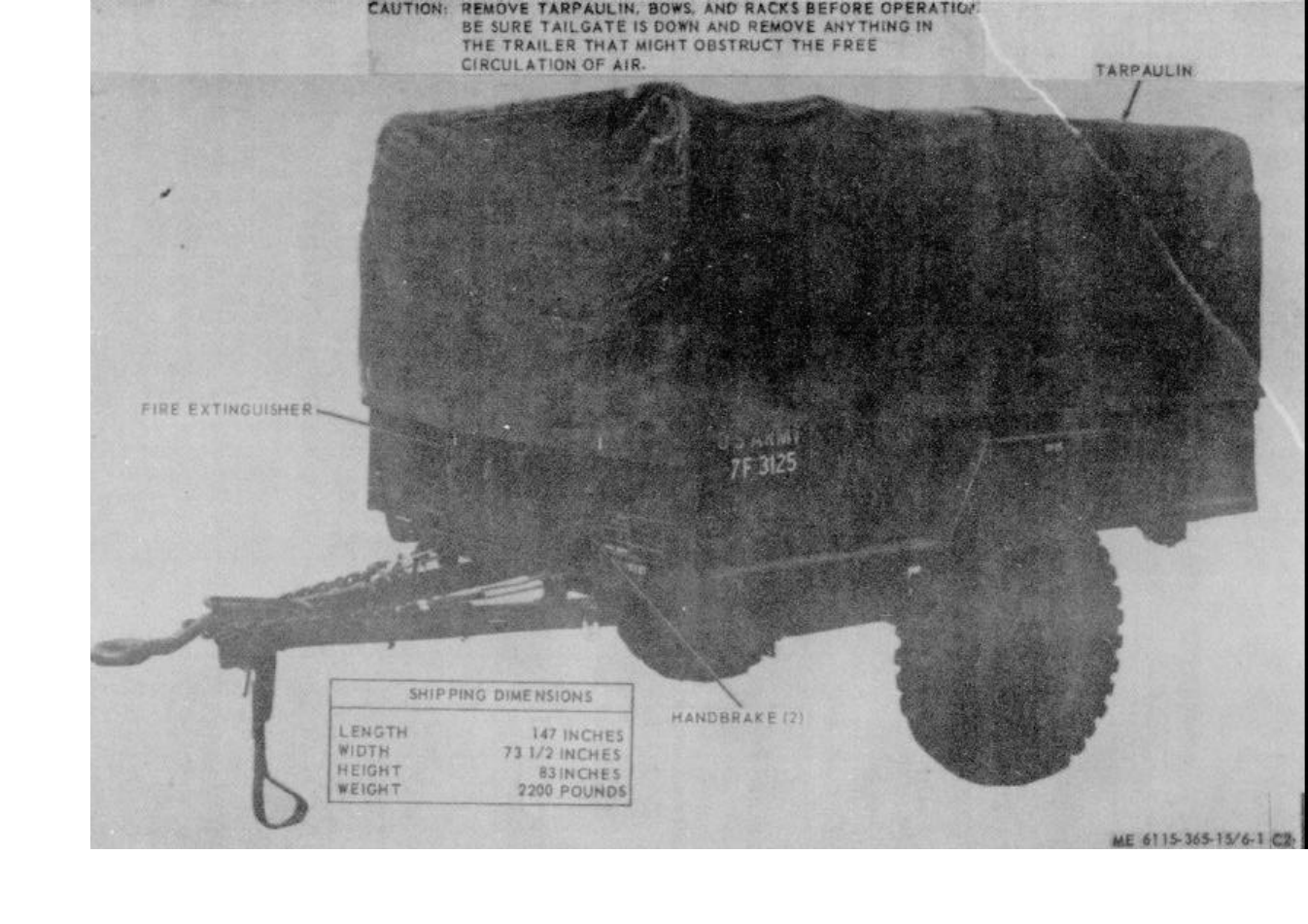
ME 6115-365-15/6-1 C2
TM 5-6115-365-15
C2
Figure 6-1. PU409A/M, right front, 3/4 view.
6-2
TM 5-6115-365-15
C2
Section II. OPERATING INSTRUCTIONS
6-3. Setting-up Instructions
a. Leveling.
(1) Locate the trailer on as level a surface as
possible in order for the generator set to operate as
efficiently as possible.
(2) Set brakes and block wheels securely to
prevent any movement. Operate handbrake at weekly
intervals to insure freedom of linkage.
(3) Pull leg prop down and adjust length for
firm contact with ground.
WARNING
Wheels must be blocked, brakes set,
and leg prop down in the support
position before attempting to roll up
the tarpaulin and before starting to
assemble or set up the equipment for
operation.
b. Preparation for Starting.
(1) Remove the canvas tarpaulin and remove
the roof bows and racks as shown in figure 6-2.
(2) Open the trailer tailgate and remove all
loose auxiliary items and anything else that might block
the free circulation of air through the trailer and around
the generator sets.
CAUTION
It is of foremost importance that
there be free circulation of air around
the generator sets at all times during
operation.
WARNING
Never operate the generator set in an
enclosed area unless the exhaust
gases are piped to the outside.
Inhalation of exhaust fumes will
result in serious illness or death.
c. Grounding. WARNING
Never operate the generator set until
it has been properly grounded.
Electrical defects in the load lines or
equipment can cause death by
electrocution when contact is made
with an ungrounded system.
(1) The generator set must be grounded prior
to operation. The ground may be any of three methods,
depending on the location and the terrain.
(a) A ground rod driven to a depth of 8
feet. (b) An underground metallic water
piping system. (c) A metal plate (9 square ft.) buried to
a depth of 4 feet.
(2) The ground lead must be No. 6 AWG
copper wire bolted or clamped to the rod, plate, or piping
system. (3) Connect the other end of the ground lead
to the trailer ground terminal stud as shown in figure 6-3.
6-4. Starting
a.Perform pre-starting and setting-up procedures
(para 6-3).
b.Start the generator as instructed in
TM 5-6115-332-12.
6-5. Stopping
Stop the generator set as instructed in
TM 5-6115-332-12.
6-6. Operation
a.Operate the generator set as instructed in
TM 5-6115-332-12.
b.Perform the fuel transfer procedure as instructed
in figure 6-4.
6-3
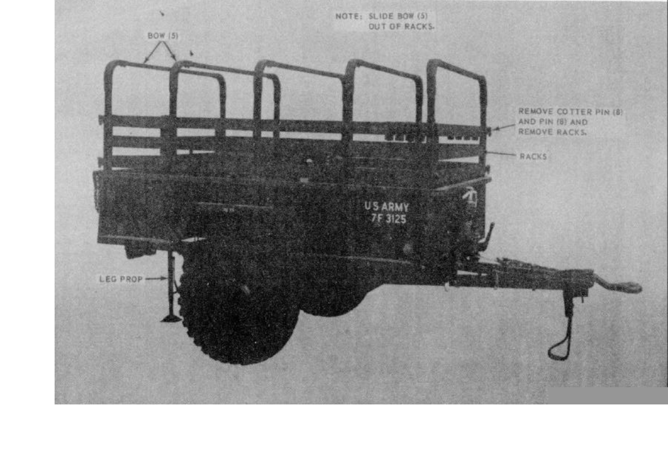
TM 5-6115-365-15
C2
Figure 6-2. Roof bows and racks, removal and installation.
ME 6115-365-15/6-2 C3
6-4
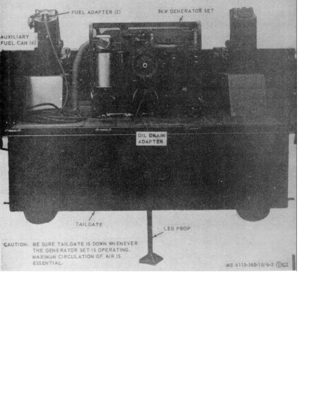
ME 6115-365-15/6-3 (1)C2
Figure 6-3 Sheet 1 of 2)
Figure 6-3 Sheet 2 of 2)
TM 5-6115-365-15
C2
Figure 6-3. PU-409A/M set up for operation (sheet 1 of 2).
6-5
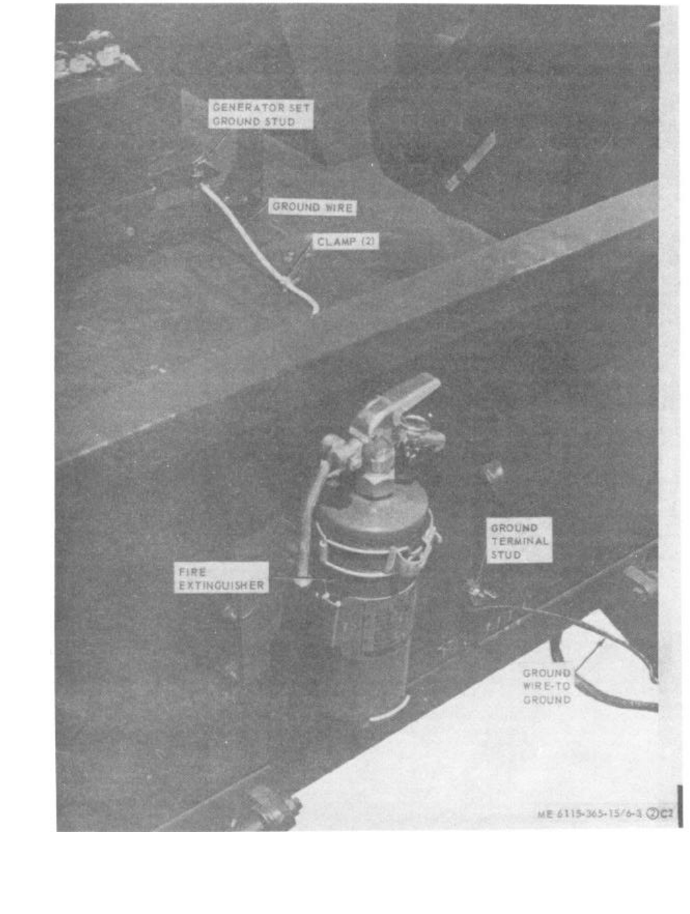
ME 6115-365-15/6-3 (2) C2
TM 5-6115-365-15
C2
Figure 6-3. PU-409A/M set up for operation (sheet 2 of 2).
6-6
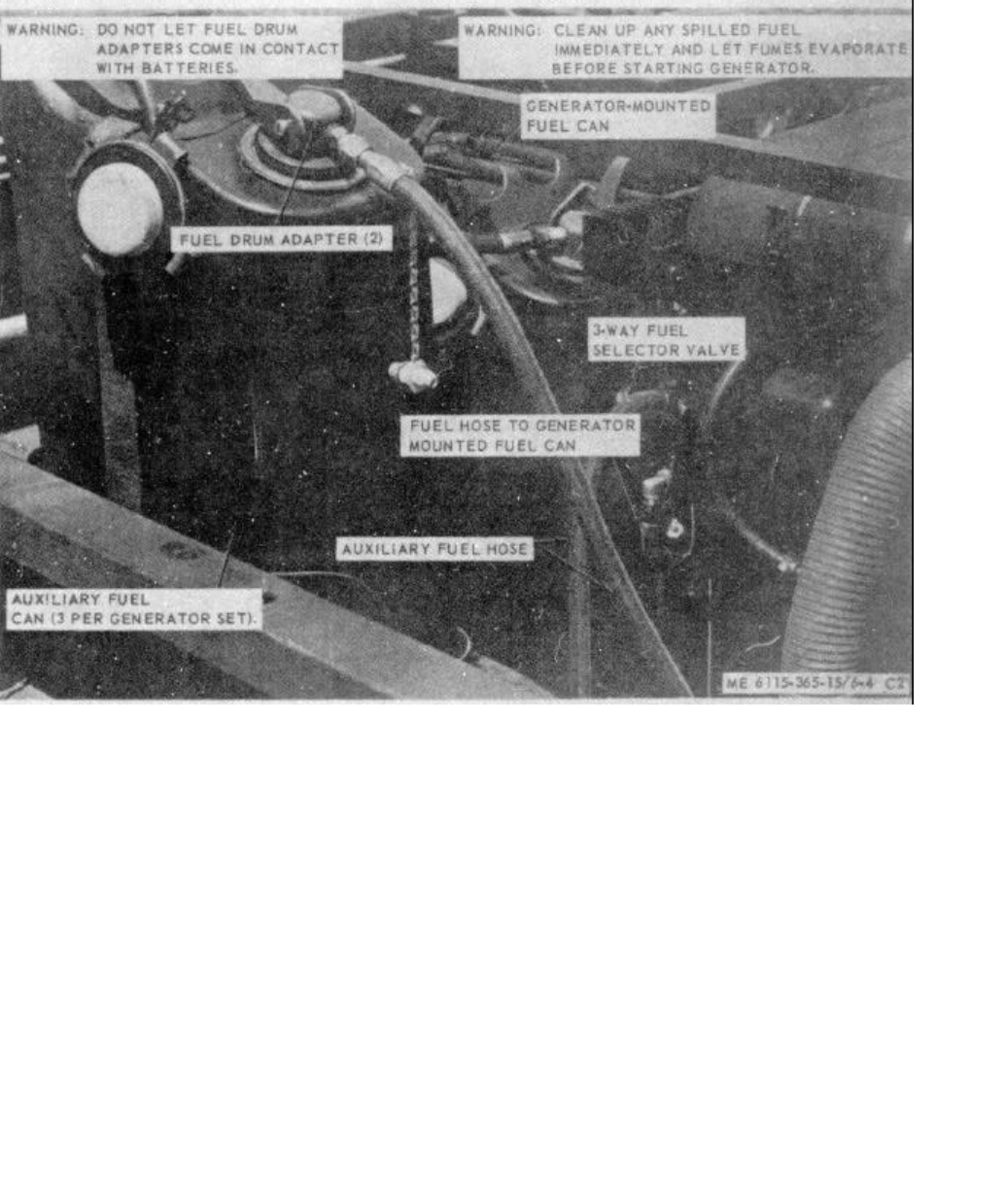
ME 6115-365-15/6-4 C2
TM 5-6115-365-15
C2
FUEL SYSTEM OPERATION:
1. CONNECT THE TWO FUEL HOSES TO THE 3-WAY SELECTOR VALVE AND CONNECT THE
OTHER ENDS TO THE ADAPTERS IN THE GENERATOR-MOUNTED FUEL CAN AND ONE OF
THE AUXILIARY FUEL CANS.
2. POSITION THE SELECTOR VALVE TO DRAW FUEL FROM THE GENERATOR-MOUNTED FUEL
CAN. START THE GENERATOR AND BRING IT UP TO OPERATING SPEED.
3. POSITION THE SELECTOR VALVE TO DRAW FUEL FROM THE AUXILIARY FUEL CAN.
OPERATE THE GENERATOR FOR ABOUT 4 HOURS ON THE AUXILIARY FUEL CAN; THEN
TURN THE SELECTOR VALVE TO DRAW FUEL FROM THE GENERATOR-MOUNTED FUEL
CAN.
4. SWITCH THE ADAPTER TO ANOTHER AUXILIARY FUEL CAN AND TURN SELECTOR VALVE
BACK TO AUXILIARY FUEL SUPPLY POSITION.
NOTE:
THIS PROCEDURE PERMITS LONGER OPERATION BETWEEN REFUELING
PERIODS
Figure 6-4. Fuel system connection and transfer procedure.
6-7
TM 5-6115-365-15
C2
Section III. ORGANIZATIONAL MAINTENANCE INSTRUCTIONS
6-7. Ground Wires and Terminal Stud
a. Removal. Remove the ground wires from the
terminal stud and generator set as shown in figure 6-3.
b. Installation. Install the ground wires and
terminal stud as shown in figure 6-3.
6-8. Tarpaulin, Roof Bows, Racks, and Leg Prop
a. Removal.
(1) Remove the tarpaulin from the unit.
(2) Remove the roof bows and racks as
shown in figure 6-2.
(3) Remove the hardware that secures the leg
prop to the rear underside of the trailer bed and remove
the leg prop.
b. Cleaning and Inspection.
(1) Clean tarpaulin, bows, and racks with
water and detergent. Clean leg prop with approved
cleaning solvent and dry thoroughly.
(2) Inspect tarpaulin for tears, holes, and
broken or missing ropes and straps, and other defects.
Inspect bows, racks, and leg prop for cracks, bends,
missing pins, and other defects.
c. Installation.
(1) Mount leg prop to the underside of the
trailer and secure with mounting hardware.
(2) Install racks and roof bows as shown in
figure 6-2.(3) Install tarpaulin and secure in desired
position.
Section IV. DIRECT SUPPORT, GENERAL SUPPORT, AND DEPOT MAINTENANCE INSTRUCTIONS
6-9. Generator Set
a. Removal. Using figure 6-5 as a guide, perform
the following steps:
(1) Disconnect fuel lines.
(2) Disconnect electrical leads and cables.
(3) Disconnect oil drain adapters.
(4) Remove the 4 bolts that secure the
generator set to the trailer bed and remove the generator
set.b. Installation. Using figure 6-5 as a guide, perform
the following steps:
(1) Secure the generator set to the trailer bed
with four bolts.
(2) Connect the oil drain adapter.
(3) Connect the electrical leads and cables.
(4) Connect the fuel lines.
6-10. Tarpaulin, Roof Bows, Racks, and Leg Prop
a. Removal. Remove the tarpaulin, roof bows,
racks, and leg prop (para 6-8).
b. Repair.
(1) Patch or sew rips and tears in the
tarpaulin. Replace damaged or missing straps or ropes.
Replace a tarpaulin that is too badly damaged to be
repaired. (2) Weld minor cracks or breaks in the bows
and leg prop. Straighten bent bows where possible.
Replace defective or missing pins and hardware.
Replace bows, racks, or leg prop that are damaged
beyond repair.
c. Installation. Install racks, roof bows, and leg
prop and install tarpaulin (para 6-8).
6-8
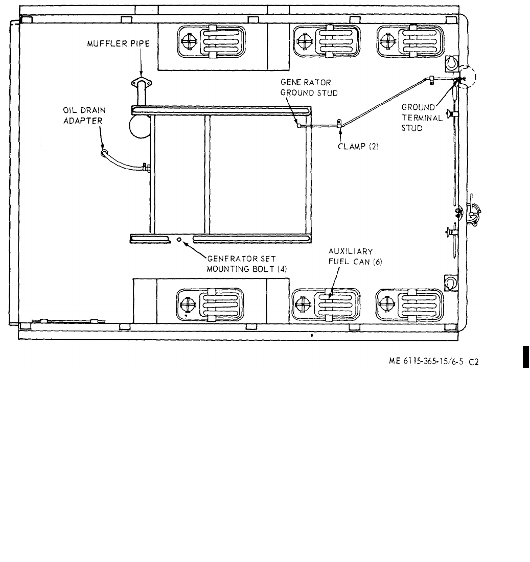
ME 6115-365-15/6-5 C2
TM 5-6115-365-15
C2
Figure 6-5. Overall component location diagram.
6-9

(1) (2) (3) (4) (5) (6) (7)
FEDERAL DESCRIPTION UNIT QTY 15-DAY ORGANIZATIONAL ILLUS-
SMR STOCK OF INC MAINTENANCE ALW RATION
CODE NUMBER USABLE MEAS IN (a) (b) (c) (d) (a) (b)
ON UNIT FIG ITEM
REF NUMBER & MFR CODE CODE 1-5 6-20 21-50 51-100 NO. NO.
TM 5-6115-365-15
C2
PART I
REPAIR PARTS FOR ORGANIZATIONAL MAINTENANCE
00001 GROUP 01 - ENGINE
00002 0106 - ENGINE LUBRICATION SYSTEM
X2 OCLAMP, HOSE: low pressure, 2 in. max od EA 26-7 11
00003 MS35842-12 (96906)
MOHOSE, FUEL, RUBBER: 875 in x 12 lg EA 16-7 12
00004 SAEJ30CL30R2 (81343)
MANUFACTURE FROM:
PO4730-684-6032 HOSE, RUBBER (12 in. required) FT SEE GRP 9501
00005
X2 ONIPPLE, PIPE, THREADED: 1/2 x 2-1/2 EA 16-7 13
00006 WWN351TYPE1 (81348)
X2 ONUT, PLAIN, HEXAGON TUBE: 5/8 x 7/8-14 EA 16-7 9
00007 AN924-10 (88044)
X2 O4730-277-6447 UNION, FLARED BULKHEAD AND UNIVERSAL FITTING EA 16-7 14
00008 AN832-10 (88044)
X2 OWASHER, LOCK, SPLIT HELICAL: 7/8 nominal size EA 16-7 10
00009 MS35338-52 (96906)
00010 GROUP 04 - EXHAUST SYSTEM
00011 0401 - MUFFLER AND PIPES
X2 O6115-947-3335 EXHAUST, TUBE EA 16-6 1
00012 13214E1487 (97403)
00013 GROUP 15 - FRAME, TOWING ATTACHMENTS AND DRAWBARS
00014 1501 - FRAME ASSEMBLY
PO2590-473-633 BRACKET ASSEMBLY EA 6****6-6 6
00015 MS53052-1 (96906)
X2 O5340-999-6277 BRACKET ASSEMBLY, HAMMER MOUNTING EA 16-7 33
00016 13214E1214 (97403)
X2 O2590-932-7298 CLAMP, GROUND ROD: 1.64 hole, spc EA 46-7 1
00017 13212E3617-1 (97403)
X2 OCLAMP, LOOP: 3/16 nominal tube, od EA 26-6 12
00018 MS2110403 (96906)
X2 O5340-914-2578 CLIP, SPRING, HAMMER, MOUNTING EA 16-7 26
00019 13214E1213-1 (97403)
X2 OHOLDER, FUEL ADAPTER EA 46-7 15
00020 13211E4889-1 (97403)
X2 O7240-920-5327 HOLDER, FUEL DRUM ADAPTER EA 26-7 23
00021 13212E3553-1 (97403)
X2 ONUT, PLAIN, HEXAGON: machine, No. 6-32 EA 86-7 19
00022 MS35649-264 (96906)
X2 ONUT, PLAIN, HEXAGON: non-mag, 3/8-16 EA 16-7 39
00023 MS16203-27 (90905)
X2 ONUT, PLAIN, HEXAGON: non-mag, 3/8-16 EA 26-7 37
00024 MS16203-39 (96906)
X2 ONUT, PLAIN, HEXAGON: screw, No. 10-24 EA 26-6 10
00025 MS35649-202 (96906)
X2 ONUT, PLAIN, WING: 3/8-16, brass EA 16-7 35
00026 MS35425-28 (96906)
X2 ONUT, SELF-LOCKING, HEXAGON: 1/4-20 EA 16-7 29
00027 MS51922-1 (96306)
6-10

(1) (2) (3) (4) (5) (6) (7)
FEDERAL DESCRIPTION UNIT QTY 15-DAY ORGANIZATIONAL ILLUS-
SMR STOCK OF INC MAINTENANCE ALW RATION
CODE NUMBER USABLE MEAS IN (a) (b) (c) (d) (a) (b)
ON UNIT FIG ITEM
REF NUMBER & MFR CODE CODE 1-5 6-20 21-50 51-100 NO. NO.
TM 5-6115-365-15
C2
X2 ONUT, SELF-LOCKING, HEXAGON: 1/4-20 EA 26-7 32
00028 MS51922-1 (96906)
X2 ONUT, SELF-LOCKING, HEXAGON: 1/4-20 EA 26-6 2
00029 MS51922-1 (96906)
X2 ONUT, SELF-LOCKING, HEXAGON: 1/4-20 EA 86-7 4
00030 MS51922-1 (96906)
X2 ONUT, SELF-LOCKING, HEXAGON: 3/8-16 EA 24 6-7 42
00031 MS51922- 17 (96906)
X2 ONUT, SELF-LOCKING: 5/16-18 EA 46-7 22
00032 MS51922-9 (96906)
X2 OPLATE, IDENTIFICATION: PU-409A/M EA 16-6 11
00033 13205E4916-12 (97403)
X2 OSCREW, CAP, HEXAGON HEAD: 1/4-20 EA 16-7 27
00034 MS90725-6 (96906)
X2 OSCREW, CAP, HEXAGON HEAD: 1/4-20 x 1 lg EA 26-6 4
00035 MS90725-8 (96906)
X2 OSCREW, CAP, HEXAGON HEAD: 1/4-20 x 3/4 lg EA 26-7 3C
00036 MS90725-6 (96906)
X2 OSCREW, CAP, HEXAGON HEAD: 3/8-16 x 7/8 lg EA 24 6-7 41
00037 MS90725-59 (96906)
X2 OSCREW, CAP, HEXAGON HEAD: 5/16-18 x 3/4 Ig EA 46-7 20
00038 MS90725-32 (96906)
X2 OSCREW, MACHINE: flat head, 1/4-20 x 7/8 lg EA 86-7 2
00039 MS35190-290 (96906)
X2 OSCREW, MACHINE: pan head, 10-24 x 5/8 in. lg EA 26-6 7
00040 MS35206-264 (96906)
X2 OSCREW, MACHINE: pan head, No. 6-32 x 1/2 EA 86-7 16
00041 MS35206-230 (96906)
X2 OSTUD, GROUNDING: 3/8-16 x 2-1/2 Ig EA 16-7 34
00042 13214E1223 (97403)
X2 OWASHER, FLAT, ELECTRIC: brass, 3/8 id EA 46-7 36
00043 AN961-616T (88044)
X2 OWASHER, FLAT, ROUND EA 24 6-7 43
00044 MS27183-15 (96906)
X2 OWASHER, FLAT, ROUND: 10-24 nominal size EA 46-6 8
00045 MS27183-8 (96906)
X2 OWASHER, FLAT, ROUND: 1/4 nominal size EA 26-6 3
00046 MS27183-10 (96906)
X2 OWASHER, FLAT, ROUND: 1/4 id nominal size EA 46-7 31
00047 MS27183-10 (96906)
X2 OWASHER, FLAT, ROUND: 1/4 nominal size EA 46-7 28
00048 MS27183-10 (96906)
X2 OWASHER, FLAT, ROUND: 1/4 id nominal size EA 86-7 3
00049 MS27183-10 (96906)
X2 OWASHER, FLAT, ROUND: 5/16 nominal size EA 86-7 21
00050 MS27183-12 (96906)
X2 OWASHER, FLAT, ROUND: 6-32 nominal size EA 86-7 17
00051 MS27183-6 (96906)
X2 OWASHER, LOCK: flat, internal tooth, 3/8 EA 36-7 38
00052 MS35333-110 (96906)
X2 OWASHER, LOCK, SPLIT HELICAL: No. 10 EA 26-6 9
00053 MS35336-43 (96906)
6-11

(1) (2) (3) (4) (5) (6) (7)
FEDERAL DESCRIPTION UNIT QTY
15-DAY ORGANIZATIONAL
ILLUS-
SMR STOCK OF INC MAINTENANCE ALW RATION
CODE NUMBER USABLE MEAS IN (a) (b) (c) (d) (a) (b)
ON UNIT FIG
ITEM
REF NUMBER & MFR CODE CODE 1-5 6-20
21-50
51-100
NO. NO.
TM 5-6115-365-15
C2
X2 OWASHER, LOCK: spilt helical, No. 6 nominal size EA 86-7 18
00054 MS35338-41 (96906)
00055 1507 - LANDING GEAR, LEVELING JACKS
X2 O5310-087-4652 NUT, SELF-LOCKING, HEXAGON: 3/8-16 EA 36-7 45
00056 MS51922-17 (96906)
X2 OSCREW, CAP, HEXAGON HEAD: 3/8-16 x 1-1/4 EA 36-7 47
00057 MS90725-62 (96906)
PO2509-420-8929 TRAILER LEG, PROP ASSEMBLY EA 1****6-7 44
00058 13214E1206 (97403)
X2 OWASHER, FLAT, ROUND: 3/8 nominal size, id EA 66-7 46
00059 MS27183-15 (96906)
00060 GROUP 22 - BODY, CHASSIS OR HULL, AND ACCESSORY ITEMS
00061 2202 - ACCESSORY ITEMS
PO7240-222-3088 CAN, GASOLINE: Military, 5 gallon EA 6****6-6 5
00062 MILC1283 (81349)
PC5120-265-7462 HAMMER HAND: double face, 8 lb EA 1****6-7 24
00063 GGGH86TYPEX (81348)
PC5975-878-3791 ROD, GROUND ASSEMBLY: with attachments EA 2****6-7 25
00064 MILR11461 (81349)
00065 GROUP 40 GENERATORS
00066 4000 - GENERATOR ASSEMBLY
X2 ONUT, SELF-LOCKING, HEXAGON: 1/2-13 EA 46-7 5
00067 MS51922-33 (96906)
X2 OSCREW, CAP, HEXAGON HEAD: 1/2-13 x 1-3/8 EA 46-7 8
00068 MS90725-112 (96906)
X2 OSPACER, GENERATOR MOUNTING EA 46-7 6
00069 13214E1222-4 (97403)
X2 OWASHER, BEVELED EA 46-7 7
00070 13206E4482-2 (97403)
00071 GROUP 42 - ELECTRICAL EQUIPMENT
00072 4216 - MISCELLANEOUS WIRING AND FITTINGS
X2 OTERMINAL, LUG, WIRE: 3/8 stud EA 16-7 40
00073 MS20659-110 (96906)
X2 O6145-395-8799 WIRE, ELECTRIC: 5 ft, copper, uninsulated EA 16-6 13
00074 QQW343TYPERB (81348)
00075 GROUP 76 - FIRE FIGHTING EQUIPMENT COMPONENTS
00076 7638 - PORTABLE FIRE FIGHTING EQUIPMENT
PC4210-555-8837 EXTINGUISHER, FIRE: 2-3/4 w/bracket EA 1****6-6 14
00077 MILE52031 (81349)
X2 O5310-088-1251 NUT, FIRE EXTINGUISHER: 1/4-20 s/lock EA 46-6 17
00078 MS51922-1 (96906)
X2 O5305-068-0502 SCREW, FIRE EXTINGUISHER MOUNTING: 1/4-20 x 3/4 EA 46-6 15
00079 MS90725-6 (96906)
X2 O5310-809-4058 WASHER, FLAT, FIRE EXTINGUISHER MOUNTING: 1/4 EA 86-6 16
00080 MS27183-10 (96906)
00081 GROUP 95 - GENERAL USE STANDARDIZED PARTS
00082 9501 - HARDWARE SUPPLIES AND BULK MATERIEL, COMMON
X2 O4730-684-6032 HOSE, FUEL, RUBBER: 875 id FT AR
00083 SAEJ30CL30R2 (81343)
X2 O 6145-395-8799 WIRE, ELECTRIC: copper, No. 6 AWG, uninsulated FT AR
00084 QQW343TYPERB (81348)
6-12

(1) (2) (3) (4) (5) (6) (7) (8) (9) (10)
DESCRIPTION 1-YR
DEPOT
QTY
30-DAY DS MAINT
30-DAY GS MAINT
ALW
PER MAINT
ALW ILLUS-
TRATION
FEDERAL USABLE UNIT INC ALLOWANCE ALLOWANCE 100 PER (a) (b)
SMR
CODE STOCK
NUMBER
ON
REF NUMBER & MFR CODE CODE OF
MEAS
IN
UNIT (a)
1-20 (b)
21-50 (c)
51-100 (a)
1-20 (b)
21-50 (c)
51-100
EQUIP
CNTGCY
100
EQUIP FIG.
NO. ITEM
NO.
TM 5-6115-365-15
C2
PART II
REPAIR PARTS FOR DS, GS,
AND DEPOT MAINTENANCE
00001 GROUP 01 - ENGINE
00002 0106 - ENGINE LUBRICATION SYSTEM
X2 OCLAMP, HOSE: low pressure, 2 in. max od EA 26-7 11
00003 MS35842-12 (96906)
MOHOSE, FUEL, RUBBER: 875 id x 12 lg EA 16-7 12
00004 SAEJ30CL30R2 (81343)
MANUFACTURE FROM:
PO4730-684-6032 HOSE, RUBBER (12 in. Ig required) FT SEE GRP 9501
00005
X2 ONIPPLE, PIPE, THREADED: 1/2 x 2-1/2 EA 16-7 13
00006 WWN351TYPE1 (81348)
X2 ONUT, PLAIN, HEXAGON TUBE: 5/8 x 7/8-14 EA 16-7 9
00007 AN924-10 (88044)
X2 O4730-277-6447 UNION, FLARED, BULKHEAD AND UNIVERSAL
00008 FITTING EA 16-7 14
AN832-10 (88044)
X2 OWASHER, LOCK, SPLIT HELICAL: 7/8 nominal
00009 size EA 16-7 10
MS35338-52 (96906)
00010 GROUP 04 - EXHAUST SYSTEM
00011 0401 - MUFFLER AND PIPES
X2 O6115-947-3335 EXHAUST, TUBE EA 16-6 1
00012 13214E1487 (97403)
00013 GROUP 15 - FRAME, TOWING ATTACHMENTS
AND DRAW BARS
00014 1501 - FRAME ASSEMBLY
PO2590-473-6331 BRACKET ASSEMBLY EA 6* * 2* * 2 10 10 6-6 6
00015 MS53052-1 (96906)
X2 O5340-999-6277 BRACKET ASSEMBLY, HAMMER MOUNTING EA 16-7 33
00016 13214E1214 (97403)
X2 O2590-932-7298 CLAMP, GROUND ROD: 1.64 hole, spc EA 46-7 1
00017 13212E3617-1 (97403)
X2 OCLAMP, LOOP:3/16 nominal tube, od EA 26-6 12
00018 MS2110403 (96906)
X2 O5340-914-2578 CLIP, SPRING, HAMMER MOUNTING EA 16-7 26
00019 13214E1213-1 (97403)
X2 OHOLDER, FUEL ADAPTER EA 46-7 15
00020 13211E4889-1 (97403)
X2 O7240-920-5327 HOLDER, FUEL DRUM ADAPTER EA 26-7 23
00021 13212E3553-1 (97403)
X2 ONUT, PLAIN, HEXAGON: machine, No. 6-32 EA 86-7 19
00022 MS35649-264 (96906)
X2 ONUT, PLAIN, HEXAGON: non-mag, 3/8-16 EA 16-7 39
00023 MS16203-27 (96906)
X2 ONUT, PLAIN, HEXAGON: non-mag, 3/8-16 EA 26-7 37
00024 MS16203-39 (96906)
X2 ONUT, PLAIN, HEXAGON: screw, No. 10-24 EA 26-6 10
00025 MS35649-202 (96906)
6-13

(1) (2) (3) (4) (5) (6) (7) (8) (9) (10)
DESCRIPTION 1-YR
DEPOT
QTY
30-DAY DS MAINT
30-DAY GS MAINT
ALW
PER MAINT
ALW ILLUS-
TRATION
FEDERAL USABLE UNIT INC ALLOWANCE ALLOWANCE 100 PER (a) (b)
SMR
CODE STOCK
NUMBER
ON
REF NUMBER & MFR CODE CODE OF
MEAS
IN
UNIT (a)
1-20 (b)
21-50 (c)
51-100 (a)
1-20 (b)
21-50 (c)
51-100
EQUIP
CNTGCY
100
EQUIP FIG.
NO. ITEM
NO.
TM 5-6115-365-15
C2
X2 ONUT, PLAIN, WING: 3/8-16, brass EA 16-7 35
00026 MS35425-28 (96906)
X2 ONUT, SELF-LOCKING, HEXAGON: 1/4-20 EA 16-7 29
00027 MS51922-1 (96906)
X2 ONUT, SELF-LOCKING, HEXAGON: 1/4-20 EA 26-7 32
00028 MS51922-1 (96906)
X2 ONUT, SELF-LOCKING, HEXAGON: 1/4-20 EA 26-6 2
00029 MS51922-1 (96906)
X2 ONUT, SELF-LOCKING, HEXAGON: 1/4-20 EA 86-7 4
00030 MS51922-1 (96906)
X2 ONUT, SELF-LOCKING, HEXAGON: 3/8-16 EA 24 6-7 42
00031 MS51922-17 (96906)
X2 ONUT, SELF-LOCKING: 5/16-18 EA 46-7 22
00032 MS51922-9 (96906)
X2 OPLATE, IDENTIFICATION: PU-409A/M EA 16-6 11
00033 13205E916-12 (97403)
X2 OSCREW, CAP, HEXAGON HEAD: 1/4-20 EA 16-7 27
00034 MS90725-6 (96906)
X2 OSCREW, CAP, HEXAGON HEAD: 1/4-20 x 1 Ig EA 26-6 4
00035 MS90725-8 (96906)
X2 OSCREW, CAP, HEXAGON HEAD: 1/4-20 x 3/4 lg EA 26-7 30
00036 MS90725-6 (96906)
X2 OSCREW, CAP, HEXAGON HEAD: 3/8-16 x 7/8 lg EA 24 6-7 41
00037 MS90725-59 (96906)
X2 OSCREW, CAP, HEXAGON HEAD: 5/16-18 x 3/4 Ig EA 46-7 20
00038 MS90725-32 (96906)
X2 OSCREW, MACHINE: flat head, 1/4-20 x 7/8 Ig EA 86-7 2
00039 MS35190-290 (96906)
X2 OSCREW, MACHINE: pan head, 10-24 x 5/8 in.
00040 lg EA 26-6 7
MS35206-264 (96906)
X2 OSCREW, MACHINE: pan head, No. 6-32 x 1/2 EA 86-7 16
00041 MS35206-230 (96906)
X2 OSTUD GROUNDING: 3/8-16 x 2-1/2 lg EA 16-7 34
00042 13214R1223 (97403)
X2 OWASHER, FLAT, ELECTRIC: brass, 3/8 id EA 46-7 36
00043 AN961- 616T (88044)
X2 OWASHER, FLAT, ROUND EA 24 6-7 43
00044 MS27183-15 (96906)
X2 OWASHER, FLAT ROUND: 10-24 nominal size EA 46-6 8
00045 MS27183-8 96906)
X2 OWASHER, FLAT, ROUND: 1/4 nominal size EA 26-6 3
00046 MS27183-10 (96906)
X2 OWASH, FLAT, ROUND: 1/4 id nominal size EA 46-7 31
00047 MS27183-10 (96906)
X2 OWASHER, FAT, ROUND: 1/4 nominal size EA 46-7 28
00048 MS27183-10 (96906)
X2 OWASHER, FLAT, ROUND: 1/4 id nominal size EA 86-7 3
00049 M627183-10 (96906)
X2 OWASHER, FLAT, ROUND: 5/16 nominal size EA 86-7 21
00050 MS27183-12 (96906)
X2 OWASHER, FLAT ROUND: 6-32 nominal size EA 86-7 17
00051 MS27183-6 (96906)
6-14

(1) (2) (3) (4) (5) (6) (7) (8) (9) (10)
DESCRIPTION 1-YR
DEPOT
QTY 30-DAY DS MAINT 30-DAY GS MAINT ALW
PER MAINT
ALW ILLUS-
TRATION
FEDERAL USABLE UNIT INC ALLOWANCE ALLOWANCE 100 PER (a) (b)
SMR
CODE STOCK
NUMBER
ON
REF NUMBER & MFR CODE CODE OF
MEAS IN
UNIT (a)
1-20 (b)
21-50
(c)
51-100
(a)
1-20 (b)
21-50
(c)
51-100
EQUIP
CNTGCY 100
EQUIP FIG.
NO. ITEM
NO.
TM 5-6115-365-15
C2
X2 OWASHER, LOCK:flat, internal tooth, 3/8 EA 36-7 36
00052 MS35333-110 (96906)
X2 OWASHER, LOCK, SPLIT HELICAL: No. 10 EA 26-6 9
00053 MS35338-43 (96906)
X2 O5310-045-3296 WASHER, LOCK:split helical, No. 6 nominal EA 86-7 18
00054 MS35338-41 (96906)
00055 1507 - LANDING GEAR, LEVELING JACKS
X2 O5310-087-4652 NUT, SELF-LOCKING, HEXAGON: 3/8-16 EA 36-7 45
00056 MS51922-17 (96906)
X2 OSCREW, CAP, HEXAGON HEAD: 3/8-16 x 1-1/4 EA 36-7 47
00057 MS90725-62 (96906)
PO2509-420-8929 TRAILER LEG, PROP ASSEMBLY EA 1******5 2 6-7 44
00058 13214E1206 (97403)
X2 OWASHER, FLAT, ROUND: 3/8 nominal size, id EA 66-7 46
00059 MS27183-15 (96906)
00060 GROUP 18 - BODY, CAB, HOOD AND HULL
00061 1810 - CARGO BODY
X2 DR 2330-898-6779 TRAILER: M101 EA 16-6 18
00062 13214E1225-2 (97403)
00063 GROUP 22 - BODY, CHASSIS OR HULL,
AND ACCESSORY ITEMS
00064 2202 - ACCESSORY ITEMS
PO7240-222-3088 CAN, GASOLINE: Military, 5 gallon EA 6******10 10 6-6 5
00065 MILC1283 (81349)
PC5120-265-7462HAMMER, HAND: double face, 8 lb EA 1* * 2* * 2 10 10 6-7 24
00066 GGGH86TYPEX (81348)
PC5975-878-3791 ROD, GROUND ASSEMBLY: with attachments EA 2* * 2* * 2 10 10 6-7 25
00067 MILR11461 (81349)
00068 GROUP 40 - GENERATORS
00069 4000 - GENERATOR ASSEMBLY
X2 FR 6115-017-8240 GENERATOR SET: 5/60 md skid, mtd EA 16-6 19
00070 MILG52279TYPE1 (81349)
X2 ONUT, SELF-LOCKING, HEXAGON: 1/2-13 EA 46-7 5
00071 MS51922-33 (96906)
X2 OSCREW, CAP, HEXAGON HEAD: 1/2-13 x 1-3/8 EA 46-7 8
00072 MS90725-112 (96906)
X2 OSPACER, GENERATOR MOUNTING EA 46-7 6
00073 13214E1222-4 (97403)
X2 OWASHER, BEVELED EA 46-7 7
00074 13206E4482-2 (97403)
00075 GROUP 42 - ELECTRICAL EQUIPMENT
00076 4216 - MISCELLANEOUS WIRING AND FITTINGS
X2 OTERMINAL, LUG, WIRE:3/8 stud EA 16-7 40
00077 MS20659-110 (96906)
X2 O6145-395-8799 WIRE, ELECTRIC: 5 ft, copper, uninsulated EA 16-6 13
00078 QQW343TYPERB (81348)
6-15

(1) (2) (3) (4) (5) (6) (7) (8) (9) (10)
DESCRIPTION 1-YR
DEPOT
QTY 30-DAY DS MAINT 30-DAY GS MAINT ALW
PER MAINT
ALW ILLUS-
TRATION
FEDERAL USABLE UNIT INC ALLOWANCE ALLOWANCE 100 PER (a) (b)
SMR
CODE STOCK
NUMBER
ON
REF NUMBER & MFR CODE CODE OF
MEAS IN
UNIT (a)
1-20 (b)
21-50 (c)
51-100 (a)
1-20 (b)
21-50 (c)
51-100
EQUIP
CNTGCY 100
EQUIP FIG.
NO. ITEM
NO.
TM 5-6115-365-15
C2
00079 GROUP 76 - FIRE FIGHTING
EQUIPMENT COMPONENTS
00080 7638 - PORTABLE FIRE
FIGHTING EQUIPMENT
PC4210-555-8837 EXTINGUISHER, FIRE: 2-3/4 w/bracket EA 1* * 2* * 2 10 10 6-6 14
00081 MILE52031 (81349)
X2 O5310-088-1251 NUT, FIRE EXTINGUISHER 1/4-20 s/lock EA 46-6 17
00082 MS5I922-1 (96906)
X2 O5305-068-0502 SCREW, FIRE EXTINGUISHER MOUNTING: 1/4-20
00083 x 3/4 EA 46-6 15
MS90725-6 (96906)
X2 O5310-809-4058 WASHER, FLAT, FIRE EXTINGUISHER MOUNTING:
00084 1/4 EA 86-6 16
MS27183-10 (96906)
00085 GROUP 95 - GENERAL USE
STANDARDIZED PARTS
00086 9501 - HARDWARE SUPPLIES AND
BULK MATERIEL, COMMON
X2 O4730-684-6032 HOSE, FUEL, RUBBER: .875 id FT AR
00087 SAEJ30CL30R2 (81343)
X2 O6145-395-8799 WIRE, ELECTRIC: copper, No. 6 AWG,
00088 uninsulated FT AR
QQW343TYPERB (81348)
6-16
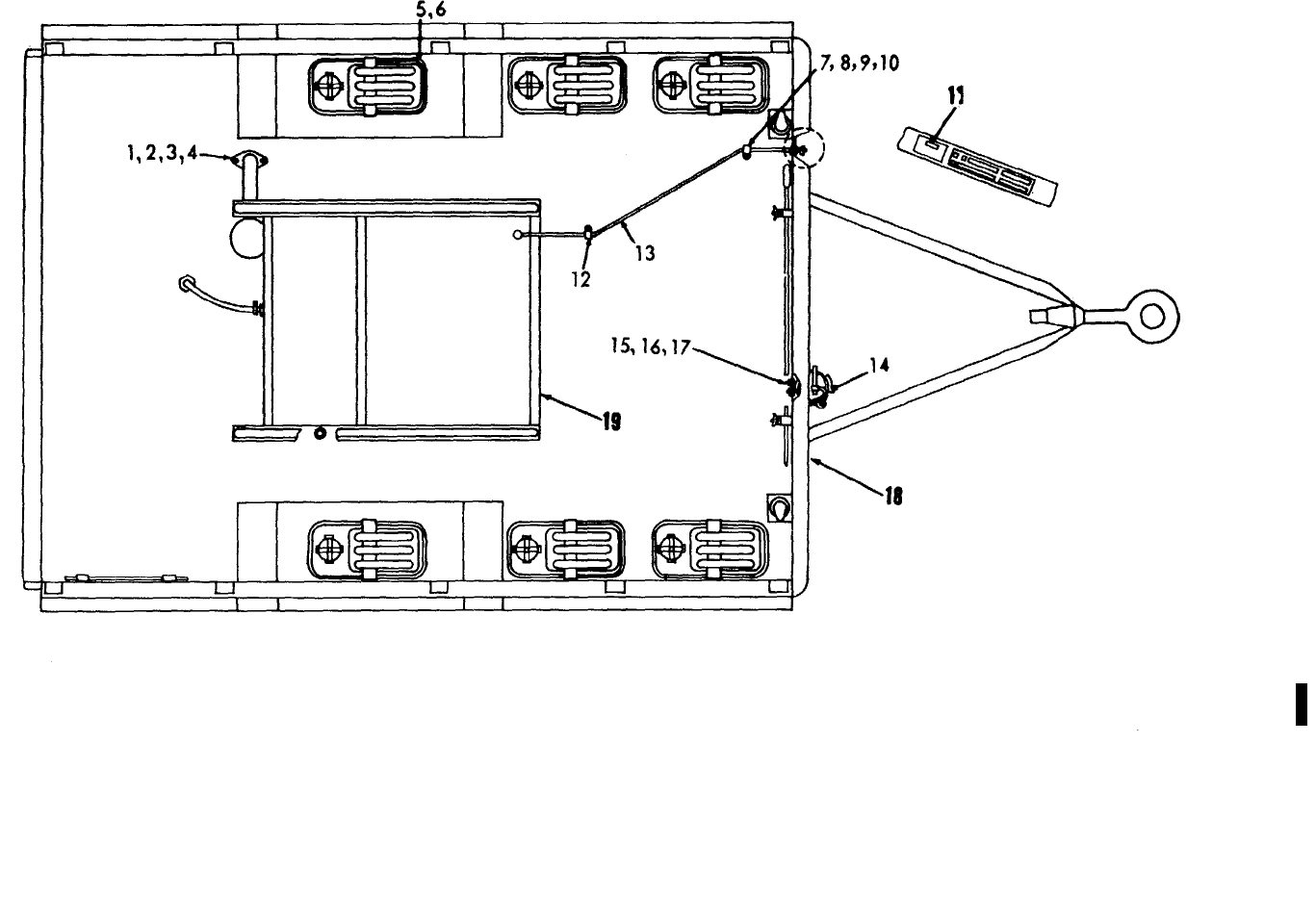
TM 5-6115-365-15
C2
Figure 6-6. Power unit components.
ME 6115-365-15/6-6 C2
6-17
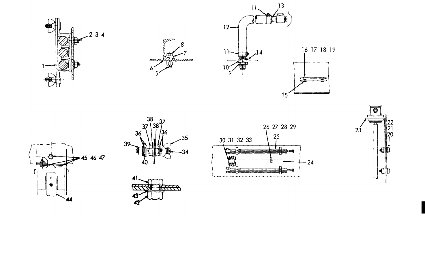
TM 5-6115-365-15
C2
Figure 6-7. Detail components.
ME 6115-365-15/6-7 C2
6-18

TM 5-6115-365-15
CHAPTER 7
GENERATOR SET PU-236B/G
Section I. DESCRIPTION AND DATA
7-1. Description
a. General. A general purpose, air-cooled,
gasoline engine-driven generator, supplying 60-cycle, 5-
kw power, mounted on a two-wheeled, box type steel
body, 1½-ton capacity, cargo trailer, model M-105E3
comprise a PU-236B/G generator set.
b. Generator. For description and further
generator information for sets with 5-kw, 60-cycle, model
SF5-MD generators, refer to applicable technical
manual, as shown on nameplate or in DA Pam 310-4.
c. Engine. For description and further generator
information for sets using a Military Standard engine
model 2A042-1, refer to applicable technical manual, as
shown on nameplate or in DA Pam 310-4.
d. Trailer. For description and further trailer
information, refer to applicable technical manual, as
shown on trailer nameplate or in DA Pam 310-4.
e. Lubrication. Lubricate model 2A042-1 Military
Standard engine in accordance with instructions outlined
in applicable lubrication order, as shown in DA Pam 310-
4. Refer to applicable technical manual and applicable
lubrication order, as shown in DA Pam 310-4, for trailer
lubrication instructions.
7-1
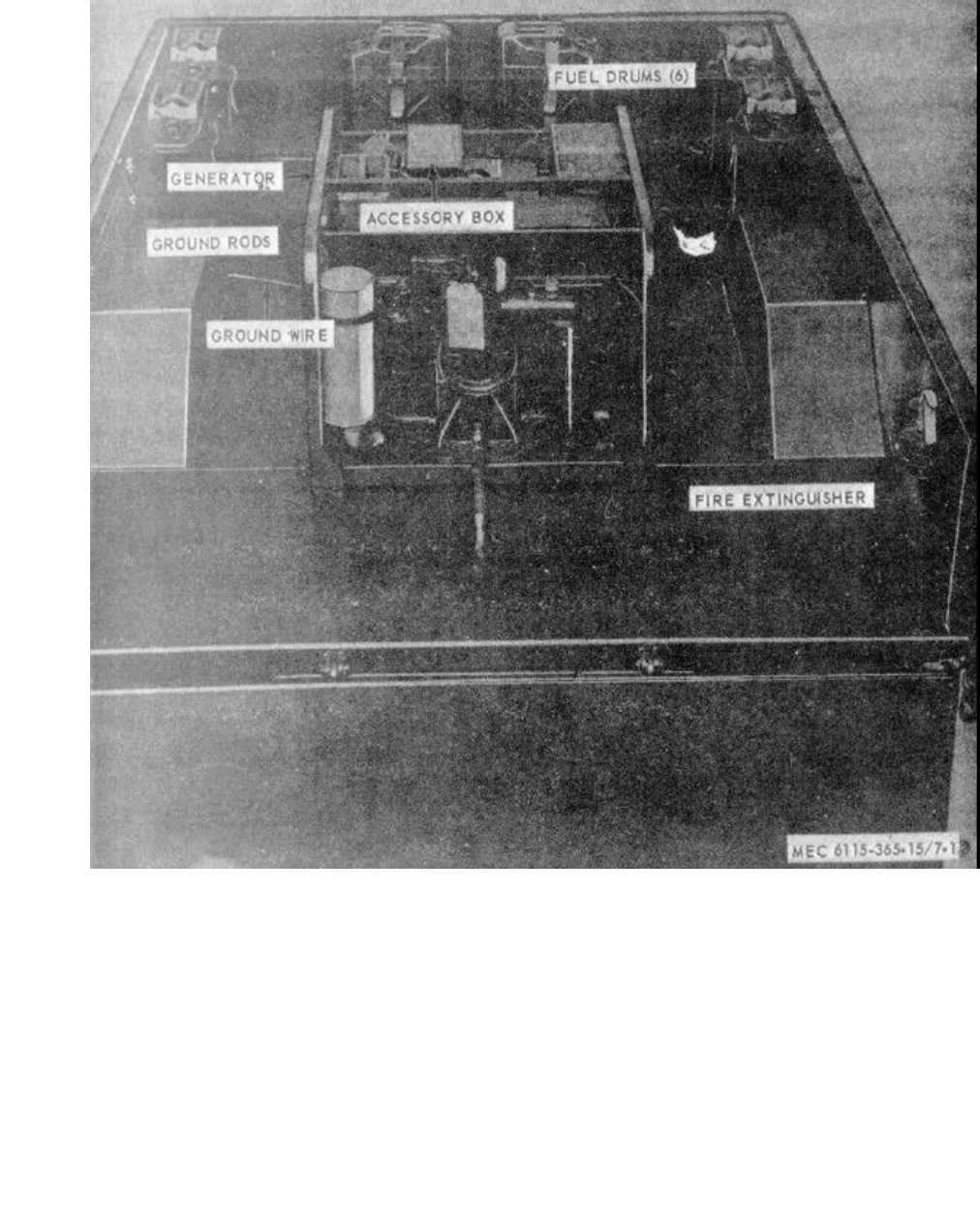
MEC 6115-365-15/7-1
TM 5-6115-365-15
Figure 7-1. Generator Set PU-236B/G.
7-2

ILLUSTSOURCE
CODES
LINE
NO.
GUIDE QTY(S) PER MAJ EQUIPS
DESCRIPTION
15 DAYS MAINTENANCE
MANUFACTURER’S ORGANIZATION DS GS
DEPOT
MAINT
MATERIAL
SOURCE
MAINT
RECOVERABILITY
FEDERAL
STOCK
NUMBER
CODE PART NO.
UNIT OF ISSUE
QTY INCORPORATED
IN UNIT
1-5 6-10 100 EQUIPMENTS
FIGURE NO.
ITEM NO.
TM 5-6115-365-15
Section II. REPAIR PARTS LIST
0002 GROUP 01 - ENGINE
0003 0106 - ENGINE LUBRICATION SYSTEM
0004 X2O 4730-278-3888 REDUCER BUSHING: 3/4-14 NPTF EXTERNAL
THD X 1/2-14 NPTF INTERNAL THD,
OIL DRAIN 81343 SAE-J530 1* * * * *
0005 X2O 4720-913-6422 HOSE, OIL DRAIN 97403 13211E4918 1* * * * * 7-2 1
0006 O4730-766-7908 UNION, FLARED TUBE, BULKHEAD: OIL DRAIN 88044 AN832-10 1 * * * * *
0007 O5310-059-6372 WASHER, LOCK: OIL DRAIN HOSE UNION 96906 MS35337-52 1* * * * *
0008 O5310-282-7822 NUT, UNION: OIL DRAIN HOSE 88044 AN924-10 1* * * * *
0009 GROUP 04 - EXHAUST SYSTEM
0010 0401 - MUFFLER AND PIPES
0011 X2O 6115-913-9291 TUBE, EXHAUST 97403 13212E3621 1* * * * *
0012 X2O CLAMP, EXHAUST TUBE SECURING 97403 13212E3622 1* * * * *
0013 O5310-209-5306 WASHER, LOCK 96906 MS35337-24 1* * * * *
0014 O5310-012-0614 NUT, PLAIN, HEXAGON 96906 MS35650-102 1* * * * *
0015 O5305-043-6755 SCREW, MACHINE 96906 MS35226-68 1* * * * *
0016 O5310-550-0777 NUT, PLAIN, HEXAGON: HOOK 96906 MS35690-402 2* * * * *
0017 GROUP 15 - FRAME, TOWING ATTACHMENTS,
AND DRAWBARS
0018 1501 - FRAME ASSEMBLY
0019 X2O 2510-706-4504 BRACKET ASSEMBLY, FUEL CAN 97403 13214E1203 6* * * * *
0020 X2O HOOK, DRIP RAIL: STRAP 97403 13212E3616 6* * * * *
0021 X2O FASTENER 97403 13214E1205 6* * * * *
0022 X2O BUCKLE 96906 MS51940-7 12 * * * * *
0023 MOSTRAP: TOP 97403 13214E1203-2 6
MANUFACTURE FROM:
0024 PO8305-267-3009 WEBBING, NYLON 06716 1403 FT SEE GRP 9501
(30 IN. REQUIRED FOR EACH STRAP)
0025 MOSTRAP: BOTTOM 97403 13214E1203-3 6
MANUFACTURE FROM:
0026 P O8305-267-3009 WEBBING, NYLON 06716 1403 FT SEE GRP 9501
(18 IN. REQUIRED FOR EACH STRAP)
0027 X2O BRACKET 97403 13214E1204 6* * * * *
0028 X2O 5305-269-3210 SCREW, CAP, HEXAGON HEAD: FUEL CAN
BRACKET MTG, 3/8-16 X 7/8 IN. LG 96906 MS90725-59 24 * * * * *
0029 O5310-809-4061 WASHER, FLAT: FUEL CAN BRACKET MTG 96906 MS27183-15 24 * * * * *
0030 O5310-087-4652 NUT, SELF-LOCKING, HEXAGON: FUEL CAN
BRACKET MTG 96906 MS51922-17 24 * * * * *
0031 X2O 5340-032-2708 LOOP, STRAP FASTENER: FUEL CAN 96906 MS51939-2 4* * * * *
0032 O5305-984-6211 SCREW, MACHINE: LOOP MTG 96906 MS35206-264 8* * * * *
0033 O5310-809-8546 WASHER, FLAT: LOOP MTG 96906 MS27183-8 8* * * * *
0034 O 5310-167-0662 WASHER, LOCK: LOOP MTG 96906 MS35337-43 8* * * * *
0035 O5310-012-0361 NUT, PLAIN, HEXAGON: LOOP MTG 96906 MS35649-102 8* * * * *
0036 X2O 6115-016-2362 HOLDER: FUEL DRUM ADAPTER EXTENSION 97403 13211E4889-1 4* * * * *
0037 O5305-889-3000 SCREW, MACHINE: EXTENSION HOLDER MTG 96906 MS35205-230 8* * * * *
0038 O5310-082-1404 WASHER, FLAT: EXTENSION HOLDER MTG 96906 MS27183-6 8* * * * *
0039 O5310-013-1181 WASHER, LOCK: EXTENSION HOLDER MTG 96906 MS35337-22 8* * * * *
0040 O5310-062-0912 NUT, PLAIN, HEXAGON: EXTENSION HOLDER MTG 96906 MS35649-64 8* * * * *
0041 X2O 7240-920-5327 HOLDER: FUEL DRUM ADAPTER 13212E3553-1 2* * * * *
0042 X2O 5306-225-8497 SCREW, BOLT MACHINE: ADAPTER HOLDER
MTG 5/16-18 X 3/4 IN. LG 96906 MS90725-32 4* * * * *
0043 O5310-081-4219 WASHER, FLAT: ADAPTER HOLDER MTG 96906 MS27183-12 8* * * * *
0044 O5310-984-3806 NUT, SELF-LOCKING, HEXAGON: ADAPTER
HOLDER MTG 96906 MS51922-9 4* * * * *
0045 X2O BRACKET ASSEMBLY, SLEDGE HAMMER 97403 13214E1214 1* * * * *
0046 X1 BRACKET 97403 13214E1215 1
0047 O5310-012-6177 NUT, PLAIN, WING 90906 MS35425-39 2* * * * *
0048 X2O PLATE, HOLD DOWN 97403 13214E1216 1* * * * *
0049 O5310-012-0392 WASHER, FLAT 96906 MS27183-10 2* * * * *
0050 O5310-043-5862 WASHER, LOCK 96906 MS35337-82 2* * * * *
0051 X2O 5340-914-2578 CLIP, SPRING: SLEDGE HAMMER HANDLE 97403 13214E1213-1 1* * * * *
0052 X2O 5305-068-0502 SCREW, CAP, HEXAGON HEAD: SLEDGE HAMMER
BRACKET AND SPRING CLIP MTG, 1/4-20 X
3/4 IN. LG 96069 MS90725-6 3* * * * *
0053 O5310-809-4058 WASHER, FLAT: SLEDGE HAMMER BRACKET,
SPRING CLIP AND GROUND ROD CLAMP MTG 96906 MS27183-10 10 * * * * *
0054 O5310-088-1251 NUT, SELF-LOCKING, HEXAGON: SLEDGE HAMMER
BRACKET, SPRING CLIP AND GROUND ROD
CLAMP MTG 96906 MS51922-1 7* * * * *
0055 X2O CLAMP ASSEMBLY, GROUND ROD 97403 13212E3617 2* * * * *
0056 O5305-958-5246 SCREW, MACHINE: GROUND ROD CLAMP MTG 90906 MS35190-289 4* * * * *
7-3
ILLUSTSOURCE
CODES
LINE
NO.
GUIDE QTY(S) PER MAJ EQUIPS
DESCRIPTION
15 DAYS MAINTENANCE
MANUFACTURER’S ORGANIZATION DS GS
DEPOT
MAINT
MATERIAL
SOURCE
MAINT
RECOVERABILITY
FEDERAL
STOCK
NUMBER
CODE PART NO.
UNIT OF ISSUE
QTY INCORPORATED
IN UNIT
1-5 6-10 100 EQUIPMENTS
FIGURE NO.
ITEM NO.
TM 5-6115-365-15
0057 O5340-526-2559 CLAMP, CUSHIONED: GROUND WIRE 96906 MS21919F2 2* * * * *
0058 O5305-614-6211 SCREW, MACHINE: GROUND WIRE CLAMP MTG 96906 MS35206-264 2* * * * *
0059 O5310-809-8546 WASHER, FLAT: GROUND WIRE CLAMP MTG 96906 MS27183-8 4* * * * *
0060 O5310-167-0662 WASHER, LOCK: GROUND WIRE CLAMP MTG 96906 MS35337-43 2* * * * *
0061 O5310-012-0361 NUT, PLAIN, HEXAGON: GROUND WIRE CLAMP
MOUNTING 96906 MS35649-102 2* * * * *
0062 X2O 5307-722-9437 STUD: GROUND 97403 13214E1223 1* * * * *
0063 X2O WASHER, LOCK: BRONZE, EXTERNAL TOOTH,
3/8 IN., GROUND STUD 96906 MS35335-91 2* * * * *
0064 O5310-720-8531 NUT, PLAIN, HEXAGON: BRASS GROUND
STUD TO TRAILER 96906 MS35691-611 2* * * * *
0065 X2O 5310-900-6323 WASHER, FLAT: BRASS, .390 ID, GROUND
STUD 96906 MS45901-7 4* * * * *
0066 O5310-720-8528 NUT, PLAIN, HEXAGON: BRASS GROUND STUD 96906 MS35690-611 1* * * * *
0067 O5310-543-4717 NUT, PLAIN, WING: BRASS, GROUND STUD 96906 MS35425-28 1* * * * *
0068 1507 - LANDING GEAR, LEVELING JACKS
(MECHANICAL OR HYDRAULIC)
0069 X2O 2590-318-6691 LEG ASSEMBLY, TRAILER PROP 97403 13214E1206 1* * * * *
0070 X2O BRACKET 97403 13214E1207 1* * * * *
0071 X2O LEG ASSEMBLY, UPPER 97403 13214E1206 1* * * * *
0072 X2O CHAIN: PIN RETAINING 97403 13214E1208-6 1* * * * *
0073 X2O PIN 97403 13214E1208-5 1* * * * *
0074 X2O LEG, BASE 97403 13214E1212 1* * * * *
0075 X2O SHAFT 97403 13214E1209 1* * * * *
0076 O4730-172-0049 FITTING, LUBRICATION 96906 MS15006-1 1* * * * *
0077 X2O SCREW 97403 13214E1210 1* * * * *
0078 X2O NUT 97403 13214E1211 1* * * * *
0079 X2O RIVET, SOLID, UNIVERSAL HEAD: 1/4 IN.
DIA, 2 IN. LG 96906 MS20613-8P32 1* * * * *
0080 X2O PIN, COTTER: 1/8 IN. DIA, 3/4 IN. LG 96906 MS24665-351 1* * * * *
0081 X2O SCREW, CAP, HEXAGON HEAD: LEG ASSEMBLY
TO TRAILER, 3/8-16 x 1 1/4 IN. LG 96906 MS90725-62 3* * * * *
0082 O5310-809-4061 WASHER, FLAT: LEG ASSEMBLY TO TRAILER 96906 MS27183-15 6* * * * *
0083 O5310-087-4652 NUT, SELF-LOCKING, HEXAGON: LEG ASSEMBLY
TO TRAILER 96906 MS51922-17 3* * * * *
0084 GROUP 16 - BODY, CAB, HOOD AND HULL
0085 1810 - CARGO BODY
(DUMP, STAKE, AND PLATFORM)
0086 X2F 2330-141-8050 TRAILER: M105 MODIFIED 97403 13214E1221-1 1* * * * *
0087 GROUP 22 - BODY CHASSIS OR HULL, AND
ACCESSORY ITEMS
0088 2202 - ACCESSORY ITEMS
0089 X2O 7240-222-3088 CAN, GASOLINE: MILITARY, 5 GAL 6* * * * * 7-2 3
0090 X2O 2910-066-1235 ADAPTER ASSEMBLY, FUEL DRUM 97403 13211E7541 2* * * * *
0091 X2O PIPE 97403 13211E7543 2* * * * *
0092 X2O WASHER, BRASS 97403 13211E7544 2* * * * *
0093 X2O SCREW, SHOULDER 97403 13211E7545 4* * * * *
0094 X2O RING, SEALING 97403 13211E7546 2* * * * *
0095 X2O WASHER, RUBBER 97403 13211E7547 2* * * * *
0096 X2O HEAD 97403 13211E7548 2* * * * *
0097 X2O WASHER, STEEL 97403 13200E6361 2* * * * *
0098 X2O CLAMP 97403 13200E6363 2* * * * *
0099 O5310-209-1239 WASHER, LOCK: SHOULDER SCREW 96906 MS35335-60 4* * * * *
0100 X2OPIPE, EXTENSION 97403 13211E7542 2* * * * *
0101 O4730-278-3357 ADAPTER, STRAIGHT: HOSE 2* * * * *
0102 2210 - DATA PLATES AND INSTRUCTION
HOLDERS
0103 X2F 9905-577-4219 PLATE, DATA: CORPS OF ENGINEERS TYPE A 97403 13212E3599 1* * * * *
0104 F5310-058-2950 WASHER, LOCK: DATA PLATE MTG 96906 MS35337-77 4* * * * *
0104A X2F 5305-058-2088 SCREW, TAPPING, THREAD FORMING: DATA
PLATE MTG NO. 2-32 X 1/4 IN. LG 4* * * * *
0105 GROUP 40 - ELECTRIC MOTORS AND GENERATORS
0106 4000 - MAJOR ASSEMBLAGE
0107 X2FR 6115-074-8830 GENERATOR, GASOLINE ENGINE DRIVEN: 5 KW,
MIL-G-5279 1* * * 7-2 4
0108 X2F 5310-520-3091 WASHER, BEVELED: GENERATOR FRAME TO
TRAILER 97403 13206E4482-2 4* * *
0109 X2F 5305-782-9495 SCREW, CAP, HEXAGON HEAD: GENERATOR FRAME
TO TRAILER, 1/2-13 X 1 1/14 IN. LG 96906 MS90725-111 4* * *
7-4
ILLUSTSOURCE
CODES
LINE
NO.
GUIDE QTY(S) PER MAJ EQUIPS
DESCRIPTION
15 DAYS MAINTENANCE
MANUFACTURER’S ORGANIZATION DS GS
DEPOT
MAINT
MATERIAL
SOURCE
MAINT
RECOVERABILITY
FEDERAL
STOCK
NUMBER
CODE PART NO.
UNIT OF ISSUE
QTY INCORPORATED
IN UNIT
1-5 6-10 100 EQUIPMENTS
FIGURE NO.
ITEM NO.
TM 5-6115-365-15
0110 X2F SPACER, SHIM 97403 13214E1222-4 4* * *
0111 X2F NUT, SELF-LOCKING, HEXAGON: generator
frame to trailer 96906 MS51922-33 4* * *
0112 4019 - RADIO INTERFERENCE SUPPRESSION
0113 MOWIRE, GROUND: generator to ground stud 17-25
MANUFACTURE FROM:
0114 PO6145-299-6188 WIRE (Length as required) FT SEE GRP 9501
0115 GROUP 76 - FIRE FIGHTING EQUIPMENT
COMPONENTS
0116 7603 - FIRE EXTINGUISHERS
0117 P1O 4210-555-8837 EXTINGUISHER, FIRE 1* * * * * 7-26
0118 X2O 5305-068-0502 SCREW, CAP, HEXAGON HEAD: extinguisher
mtg, 1/4-20 x 3/4 in. lg 96906 MS90725-6 4* * * * *
0119 O5310-809-4058 WASHER, FLAT: extinguisher mtg 96906 MS27183-10 8* * * * *
0120 O5310-088-1251 NUT, SELF-LOCKING, HEXAGON: extinguisher
mounting 96906 MS51922-1 4* * * * *
0121 GROUP 95 - GENERAL USE STANDARDIZED
PARTS
0122 9501 - BULK MATERIAL
0123 PO8305-267-3009 WEBBING, NYLON 06716 1403 FT * * * * *
0124 PO6145-299-6188 WIRE, ELECTRICAL FT * * * * *
Change 8 7-5
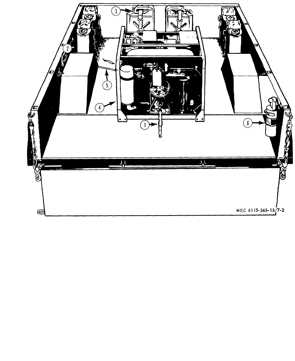
MEC 6115-365-15/7-2
TM 5-6115-365-15
1Hose 4Generator
2Clamp 5Wire
3Can 6Extinguisher
Figure 7-2. Accessories.
7-6

TM 5-6115-365-15
CHAPTER 8
GENERATOR SETS PU-236/G AND PU-236A/G
Section I. DESCRIPTION AND DATA
8-1. Description
a. General. A 5-kw, 60-cycle, gasoline engine
driven generator, mounted on a two-wheeled, box type,
steel body, 11/2-ton capacity, model M105-A-2, M105-E-
3, or Model M105-A-1 cargo trailer, comprise Generator
Sets PU-236/G and PU-236A/G.
b. Function. The PU-236/G and PU-236A/G
provide a trailer-mounted source of 5-kw, 120/240-volt,
60-cycle, single-phase ac power for various radio sets.
c. Difference in Models. The PU-236/G uses a
PU-58/G generator (O'Keefe and Merritt, Number 1000-
36), driven by a Willys Overland model MB-441 engine.
The PU-236A/G uses either a Kurtz and Root generator,
model XP536, or a Master Vibrator generator model
EG144.
d. Generator. For description and further
information about units having Master Electric Company
style 224936, type AG generator and/or Master Vibrator
generator set model EG-144 refer to applicable technical
manual, as shown on nameplate or in DA Pam 310-4.
For units having a Kurtz and Root Company model
XP536 generator and/or Hol-Gar model CE-52M-AC
generator set refer to applicable technical manuals, as
shown on nameplate or in DA Pam 310-4.
e. Engine. For description and further information
on sets using Aerojet General Corporation model
305665 engine refer to applicable technical manual, as
shown on nameplate or in DA Pam 310-4. Applicable
technical manuals, as shown on nameplate or in DA
Pam 310-4, describe and provide instructions for sets
equipped with Continental Engine model NS56.
f. Power Unit. For description and additional
information on PU-58/G refer to applicable technical
manual, as shown on generator set nameplate or in DA
Pam 310-4.
g. Trailer. For description and further trailer
information refer to applicable technical manual, as
shown on trailer nameplate or in DA Pam 310-4.
h. Lubrication. Lubricate the trailer as prescribed
in applicable lubrication order, as shown in DA Pam 310-
4. Lubrication order, as shown in DA Pam 310-4.
contains instructions for lubrication of the Hol-Gar model
CE-52M-AC Generator Set. Lubricate Master Vibrator
model EG-144 generator set in accordance with
instructions outlined in applicable lubrication order, as
shown in DA Pam 310-4. Lubricate Aerojet General
Corporation model 305665 engine as directed by
applicable lubrication order, as shown in DA Pam 310-4.
Refer to applicable technical manual, as shown in DA
Pam 310-4, and figure 16 for lubricating instructions for
the PU-58/G power unit.
8-1
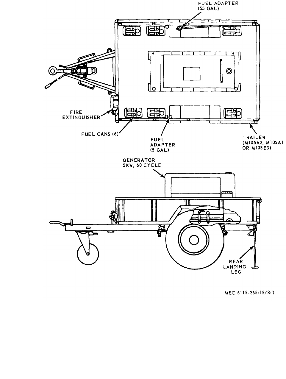
MEC 6115-365-15/8-1
TM 5-6115-365-15
Figure 8-1. Generator Set PU-236A/G.
8-2
ILLUSTSOURCE
CODES
LINE
NO.
GUIDE QTY(S) PER MAJ EQUIPS
DESCRIPTION
15 DAYS MAINTENANCE
MANUFACTURER’S ORGANIZATION DS GS
DEPOT
MAINT
MATERIAL
SOURCE
MAINT
RECOVERABILITY
FEDERAL
STOCK
NUMBER
CODE PART NO.
UNIT OF ISSUE
QTY INCORPORATED
IN UNIT
1-5 6-10 100 EQUIPMENTS
FIGURE NO.
ITEM NO.
TM 5-6115-365-15
Section II. REPAIR PARTS LIST
0001 SECTION II - REPAIR PARTS LIST
0002 GROUP 15 - FRAME, TOWING ATTACHMENTS,
AND DRAWBARS
0003 1501 - FRAME ASSEMBLY
0004 X2O 2510-706-4504 BRACKET ASSEMBLY, FUEL CAN 97403 13214E1203 6* * * * *
0005 GROUP 18 - BODY, CAB, HOOD AND HULL
0006 1810 - CARGO BODY
(DUMP, STAKE, AND PLATFORM)
0007 X2F 2330-835-8631 TRAILER, CARGO: M105E3 MODIFIED 1* * *
0008 GROUP 22 - BODY CHASSIS OR HULL, AND
ACCESSORY ITEMS
0009 2202 - ACCESSORY ITEMS
0010 X2O 7240-222-3088 CAN, GASOLINE: MILITARY, 5 GAL 6* * * * *
0011 X2O 6115-379-3991 ADAPTER KIT, FUEL DRUM: 55 GAL 1* * * * *
0012 X2O 7240-177-6154 TUBE: FLEXIBLE NOZZLE 1* * * * *
0013 GROUP 40 - ELECTRIC MOTORS AND GENERATORS
0014 4000 - GENERATOR SET
0015 X2FR 6115-635-8590 GENERATOR SET, GASOLINE ENGINE DRIVEN:
5 KW 1* * *
0016 GROUP 76 - FIRE FIGHTING EQUIPMENT
COMPONENTS
0017 7603 - FIRE EXTINGUISHERS
0018 P1O 4210-555-8837 EXTINGUISHER, FIRE 1* * * * *
8-3

TM 5-6115-365-15
CHAPTER 9
GENERATOR SET PU-401/M
Section I. DESCRIPTION AND DATA
9-1. Description
a. General. A diesel engine-driven, 45-kw, 400
cycle, ac generator, mounted on a two-wheeled, flatbed
steel body, 2½-ton capacity, model M-200A1 trailer
comprise the Generator Set PU-401/M.
b. Function. The PU-401/M Generator Set is part
of Defense System, Antiaircraft AN/MSG-4. The unit is a
mobile source of 400-cycle power for the Weapons
Monitoring Center, the Radar Processing Center, and
the Maintenance Van.
c. Generator Sets. For description and further
information on Stewart and Stevenson sets, model
52300, refer to applicable technical manual, as shown
on generator set nameplates, or in DA Pam 310-4. See
applicable technical manuals, as shown on generator set
nameplates or DA Pam 310-4, for description and further
information on Consolidated Diesel model 4060
Generator Sets.
d. Generators. For repair parts information on sets
having General Electric Company model No. 5SJ1006A3
Generators, refer to applicable technical manuals, as
shown on nameplates or in DA Pam 310-4.
e. Engine. Applicable technical manual, as shown
on nameplates or in DA Pam 310-4, contains description
and maintenance instructions for the Cummins model
J1S-600 diesel engines.
f. Trailer. For description and further trailer
information refer to applicable technical manual, as
shown on trailer nameplate or in DA Pam 310-4.
g. Lubrication. Applicable lubrication order, as
shown in DA Pam 310-4, contains lubrication
instructions for Consolidated Diesel model 4060 diesel
engine-driven generators. Refer to applicable lubrication
order, as shown in DA Pam 310-4, for lubricating
instructions for Stewart and Stevenson model 52300
diesel engine-driven generators. Cummins model J1S-
600 diesel engine lubricating instructions are contained
within applicable lubrication order, as shown in DA Pam
310-4. Refer to applicable technical manual, as shown
in DA Pam 310-4, for trailer lubrication information.
9-1
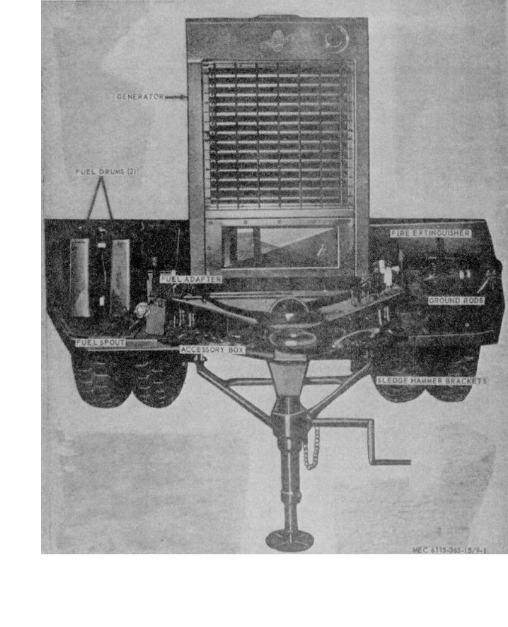
MEC 6115-365-15/9-1
TM 5-6115-365-15
Figure 9-1. Generator Set PU-401/M.
9-2
ILLUSTSOURCE
CODES
LINE
NO.
GUIDE QTY(S) PER MAJ EQUIPS
DESCRIPTION
15 DAYS MAINTENANCE
MANUFACTURER’S ORGANIZATION DS GS
DEPOT
MAINT
MATERIAL
SOURCE
MAINT
RECOVERABILITY
FEDERAL
STOCK
NUMBER
CODE PART NO.
UNIT OF ISSUE
QTY INCORPORATED
IN UNIT
1-5 6-10 100 EQUIPMENTS
FIGURE NO.
ITEM NO.
TM 5-6115-365-15
Section II. REPAIR PARTS LIST
0002 GROUP 15 - FRAME, TOWING ATTACHMENTS,
AND DRAWBARS
0003 1501 - FRAME ASSEMBLY
0004 X2O 2590-413-6331 BRACKET, LIQUID CONTAINER, FUEL CAN 97403 13214E1203 2* * * * * 9-2 1
0005 X2O BRACKET 97403 13214E1204 2* * * * *
0006 X2O BUCKLE 96906 MS51940-7 2* * * * *
0007 X2O FASTENER 97403 13214E1205 2* * * * *
0008 X2O HOOK, DRIP RAIL 97403 13212E3615 2* * * * *
0009 MOSTRAP, BOTTOM 97403 13214E1203-3 2
MANUFACTURE FROM:
0010 PO8305-267-3009 WEBBING, NYLON 06716 1403 FT SEE GRP 9501
(18 IN. REQUIRED FOR EACH STRAP)
0011 MOSTRAP, TOP 97403 13214E1203-2 2
MANUFACTURE FROM:
0012 PO8305-267-3009 WEBBING, NYLON 06716 1403 FT SEE GRP 9501
(18 IN. REQUIRED FOR EACH STRAP)
0013 O5310-984-3806 NUT, SELF-LOCKING, HEXAGON: FUEL CAN
BRACKET MTG 96906 MS51922-9 8* * * * *
0014 X2O 5305-225-8499 BOLT, MACHINE: FUEL CAN BRACKET MTG 96906 MS90725-34 8* * * * *
0015 O5310-081-4219 WASHER, FLAT: FUEL CAN BRACKET MTG 96906 MS27183-12 8* * * * *
0016 X2O BRACKET, MOUNTING, GROUND ROD 97403 13214E1288 1* * * * *
0017 X2O BRACKET, GROUND ROD 14850 A116-726 1* * * * *
0018 X2O HOLDER, GROUND ROD 14850 D116-125Y 1* * * * *
0019 X2O SCREW, CAP, HEXAGON HEAD: GROUND ROD MTG 96906 MS90725-33 2* * * * *
0020 X2O 5310-081-4219 WASHER, FLAT: GROUND ROD MTG 96906 MS27183-12 2* * * * *
0021 X2O 5310-984-3806 NUT, SELF-LOCKING: GROUND ROD MTG 96906 MS51922-9 2* * * * *
0022 X2O BRACKET, DOUBLE ANGLE, SLEDGE HAMMER 97403 13214E1214 1* * * * *
0023 X2O BRACKET, SLEDGE HAMMER 14850 A116-740Y 1* * * * *
0024 X2O HOLDER, SLEDGE HAMMER 14850 D116-741X 1* * * * *
0025 X2O 5340-9114-2578 CLIP, SPRING TENSION: SLEDGE HAMMER
BRACKET 97403 13214E1213-1 1* * * * *
0026 O5310-088-1251 NUT, SELF-LOCKING, HEXAGON: SLEDGE HAMMER
BRACKET MTG 96906 MS51922-1 3* * * * *
0027 O5305-068-0502 SCREW, CAP, HEXAGON HEAD: SLEDGE HAMMER
BRACKET MTG 96906 MS90725-6 3* * * * *
0028 O5310-809-4058 WASHER, FLAT: SLEDGE HAMMER BRACKET MTG 96906 MS27183-10 3* * * * *
0029 X2O 5307-722-9437 STUD, CONTINUOUS THREAD, GROUND WIRE 97403 13214E1223 1* * * * *
0030 O5310-720-8530 NUT, PLAIN, HEXAGON: GROUND STUD 96906 MS35691-611 3* * * * *
0031 O5310-543-4717 NUT, PLAIN, WING: GROUND STUD 96906 MS35425-28 1* * * * *
0032 X2O 5310-900-6323 WASHER, FLAT: GROUND STUD 96906 MS45901-7 4* * * * *
0033 X2O WASHER, LOCK, FLAT, EXTERNAL TOOTH:
GROUND STUD, PHOSPHOR BRONZE, 3/8 lb. 96906 MS35335-91 1* * * * *
0034 X2O 5975-878-3791 ROD, GROUND TYPEIISTYLE2 1* * * * *
0035 GROUP 18 - BODY, CAB, HOOD AND HULL
0036 1808 - STOWAGE RACKS, BOXES, STRAPS,
CARRYING CASES, CABLE REELS,
HOSE REELS, ETC.
0037 X2O 6115-705-4604 BOX, ACCESSORY, STOWAGE 97403 13214E1273 1* * * * * 9-2 3
0038 O5310-984-3806 NUT, SELF-LOCKING, HEXAGON: ACCESSORY
BOX MTG 96906 MS51922-9 2* * * * *
0039 X2O 5306-225-8499 BOLT, MACHINE: ACCESSORY BOX MTG 96906 MS90725-34 2* * * * *
0040 O5310-081-4219 WASHER, FLAT: ACCESSORY BOX MTG 96906 MS27183-12 2* * * * *
0041 1810 - CARGO BODY
(DUMP, STAKE, AND PLATFORM)
0042 X2FR 2330-331-2307 CHASSIS, TRAILER: MODEL M200A1 97403 13214E1257 1* * *
0043 GROUP 22 - BODY CHASSIS OR HULL, AND
ACCESSORY ITEMS
0044 2202 - ACCESSORY ITEMS
0045 X2O CABLE ASSEMBLY, POWER 97403 13214E1275 1* * * * *
0046 X2O 6145-189-6695 LEAD, GROUND 1* * * * *
0047 X2O 7040-222-3088 CAN, GASOLINE, MILITARY: 5 GAL 2* * * * * 9-2 2
0048 X2O 7240-177-6154 SPOUT, CAN, FLEXIBLE 96906 MILS1235 1* * * * *
0049 X2O 2910-066-1235 ADAPTER, ASSEMBLY, FUEL DRUM 97403 13211E7541 1* * * * *
0050 X2O PIPE 97403 13211E7543 1* * * * *
0051 X2O WASHER, BRASS 97403 13211E7544 2* * * * *
0052 X2O SCREW, SHOULDER 97403 13211E7545 2* * * * *
0053 X2O RING, SEALING 97403 13211E7546 1* * * * *
9-3
ILLUSTSOURCE
CODES
LINE
NO.
GUIDE QTY(S) PER MAJ EQUIPS
DESCRIPTION
15 DAYS MAINTENANCE
MANUFACTURER’S ORGANIZATION DS GS
DEPOT
MAINT
MATERIAL
SOURCE
MAINT
RECOVERABILITY
FEDERAL
STOCK
NUMBER
CODE PART NO.
UNIT OF ISSUE
QTY INCORPORATED
IN UNIT
1-5 6-10 100 EQUIPMENTS
FIGURE NO.
ITEM NO.
TM 5-6115-365-15
0054 X2O WASHER, RUBBER 97403 13211E7547 1* * * * *
0055 X2O HEAD 97403 13200E7548 1* * * * *
0056 X2O WASHER, STEEL 97403 13200E6861 1* * * * *
0057 X2O CLAMP 97403 13200E6363 1* * * * *
0058 O5310-209-1239 WASHER, LOCK 96906 MS35355-60 1* * * * *
0059 X2O PIPE, EXTENSION 97403 13211E7542 1* * * * *
0060 O4730-278-3357 ADAPTER, STRAIGHT: hose 1* * * * *
0061 2210 - DATA PLATES AND INSTRUCTION
HOLDERS
0062 X2O NAMEPLATE: ACCESSORY BOX 14850 D900-468x 1* * * * *
0063 X2O NAMEPLATE: FIRE EXTINGUISHER 14850 D9-284-3 2* * * * *
0064 X2O NAMEPLATE: GROUND ROD 14850 D9-28A2 1* * * * *
0065 X2O NAMEPLATE: GROUND ROD 14850 D9-11A 1* * * * *
0066 X2O PLATE, IDENTIFICATION: POWER UNIT 97403 13212E3599 1* * * * *
0067 X2O NAMEPLATE: SLEDGE HAMMER 14850 D9-28A1 1* * * * *
0068 X2O NAMEPLATE, IDENTIFICATION: DISTRIBUTION
BOX 97403 13214E1284 1* * * * *
0069 X2O NAMEPLATE: WIRING DIAGRAM 97403 13214E1283 1* * * * *
0070 X2O 5305-058-2088 SCREW, TAPPING, THREAD FORMING:
NAMEPLATE MTG 96906 MS24622-3 2* * * * *
0071 X2O SCREW, TAPPING: PAN HEAD, NAMEPLATE MTG,
No. 4-24, 1/4 IN. LG 96906 MS24622-8 8* * * * *
0072 X2O SCREW, TAPPING: PAN HEAD, NAMEPLATE
No. 14, 5/16 IN. LG 96906 MS24646-9 14 * * * * *
0073 GROUP 40 - ELECTRIC MOTORS AND GENERATORS
0074 4000 - MAJOR ASSEMBLAGE
0075 X2FR 6115-823-2217 GENERATOR SET, DIESEL ENGINE TRAILER
MOUNTED 971403 13214E1255 1* * * 9-2 5
0076 X2F 5306-180-0094 BOLT, MACHINE AIRCRAFT, 5/8-18, 1 41/61
IN. LG GENERATOR MTG 88044 AN10-14A 4* * *
0077 X2F 5310-269-4040 NUT, SELF LOCKING, HEXAGON: GENERATOR
MOUNTING 96906 MS51922-49 4* * *
0078 X2F WASHER, BEVELED: GENERATOR MTG 97403 13206E4482-3 4* * *
0079 X2F 5310-823-8803 WASHER, FLAT: GENERATOR MTG 96906 MS27183-21 4* * *
0080 4019 - RADIO INTERFERENCE SUPPRESSION
0081 MOWIRE, ELECTRICAL: GENERATOR TO GROUND
STUD 81349 QQW-343 1
MANUFACTURE FROM:
0082 PO6145-857-6903 WIRE, ELECTRICAL (LENGTH AS REQUIRED) FT SEE RP 9501
0083 GROUP 42 - ELECTRICAL EQUIPMENT
0084 4201 - TRANSFORMER, POWER LINE OR
DISTRIBUTION
0085 X2O DISTRIBUTION BOX ASSEMBLY 97403 13214E1276-1 1* * * * *
0086 X2O BOX: DISTRIBUTION 97403 13214E1277 1* * * * *
0087 X2O TERMINAL BOARD: DISTRIBUTION 97403 13214E1278 1* * * * *
0088 X2O 5305-068-0502 SCREW, CAP, HEXAGON HEAD: TERMINAL
BOARD MTG 96906 MS90725-6 6* * * * *
0089 X2O 5310-809-4058 WASHER, FLAT: TERMINAL BOARD MTG 96906 MS27183-10 4* * * * *
0090 X2O 5310-088-1251 NUT, SELF LOCKING, HEXAGON: TERMINAL
BOARD MTG 96906 MS51922-1 6* * * * *
0091 X2O STUD, SHOULDER: DISTRIBUTION BOX 97403 13214E1279-3 4* * * * *
0092 X2O 5310-900-6323 WASHER, FLAT: DISTRIBUTION BOX MTG 96906 MS45901-7 20 * * * * *
0093 X2O 5310 576-0548 WASHER, LOCK: DISTRIBUTION BOX MTG 96906 MS35337-103 12 * * * * *
0094 X2O 5310-685-2632 NUT, PLAIN, HEXAGON: DISTRIBUTION BOX
MOUNTING 96906 MS35691-612 16 * * * * *
0095 X2O PANEL 97403 13214E1280 1* * * * *
0096 X2O SCREW, MACHINE: PAN HEAD, PANEL MTG 96906 MS35206-278 8* * * * *
0097 X2O NAMEPLATE: DISTRIBUTION BOX 97403 13214E1284 1SEE GRP 2210
0098 X2O CABLE ASSEMBLY: DISTRIBUTION BOX 97403 13214E1282-1 1* * * * *
0099 X2O CABLE ASSEMBLY: DISTRIBUTION BOX 97403 13214E1282-2 1* * * * *
0100 X2O SCREW, MACHINE: PAN HEAD, No. 10-32
58 IN. LG 96906 MS35207-264 8* * * * *
0101 X2O 5310-809-8546 WASHER, FLAT 96906 MS27183-8 8* * * * *
0102 X2O 5310-754-2034 WASHER, LOCK 96906 MS35337-102 8* * * * *
0103 X2O 5310-012-0614 NUT, PLAIN, HEXAGON96906 MS35650-102 8* * * * *
0104 X2O NAMEPLATE: WIRING DIAGRAM 97403 13214E1283 1SEE GRP 2210
0105 X2O CONNECTOR AND LOCKNUT 97403 13212E3582-3 1* * * * *
0106 X2O COVER, ELECTRICAL CONNECTOR 96906 MS17349N36B 2* * * * *'
9-4

ILLUSTSOURCE
CODES
LINE
NO.
GUIDE QTY(S) PER MAJ EQUIPS
DESCRIPTION
15 DAYS MAINTENANCE
MANUFACTURER’S ORGANIZATION DS GS
DEPOT
MAINT
MATERIAL
SOURCE
MAINT
RECOVERABILITY
FEDERAL
STOCK
NUMBER
CODE PART NO.
UNIT OF ISSUE
QTY INCORPORATED
IN UNIT
1-5 6-10 100 EQUIPMENTS
FIGURE NO.
ITEM NO.
TM 5-6115-365-15
0107 GROUP 76 - FIRE FIGHTING EQUIPMENT
COMPONENTS
0108 7603 - FIRE EXTINGUISHERS
0109 P1O 4210-555-8837 EXTINGUISHER, FIRE,
MONOBROMOTRIFLUOROMETHANE 96909 MILE52031 1* * * * * 9-2 4
0110 X2O 6115-606-9938 BRACKET, FIRE EXTINGUISHER 14850 D443C 1* * * * *
(USED WITH FIRE EXTINGUISHER STOCK No.
4210-555-8837)
0111 X2O 5305-068-0502 SCREW, CAP, HEXAGON HEAD: EXTINGUISHER
MTG 1/4-20, 3/4 IN. LG 96906 MS90725-6 4* * * * *
0112 O5310-809-4058 WASHER, FLAT: EXTINGUISHER MTG 96906 MS27183-10 8* * * * *
0113 O5310-088-1251 NUT, SELF-LOCKING, HEXAGON: EXTINGUISHER 96906 MS51922-1 8* * * * *
0114 O4210-202-7858 EXTINGUISHER, FIRE, CARBON DIOXIDE 96906 MILE468 1* * * * *
0115 X2O6115-606-9338 BRACKET, FIRE EXTINGUISHER 1* * * * *
(USED WITH FIRE EXTINGUISHER STOCK No.
4210-202-7858)
0116 GROUP 95 - GENERAL USE STANDARDIZED
PARTS
0117 9501 - BULK MATERIAL
0118 PO8305-267-3009 WEBBING, NYLON06716 1403 FT * * * * *
0119 PO6145-857-6903 WIRE, ELECTRICAL FT * * * * *
9-5
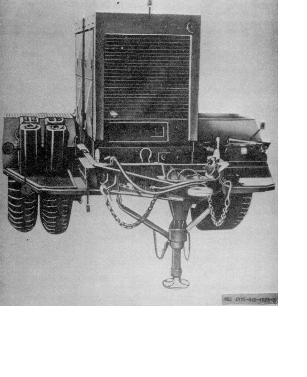
MEC 6115-368-15/9-2
TM 5-6115-365-15
1Bracket 4Extinguisher
2Box 5Generator
3Can
Figure 9-2. Accessories.
9-7

TM 5-6115-365-15
CHAPTER 10
GENERATOR SET PU-495/G
Section I. DESCRIPTION AND DATA
10-1. Description
a. General. A 100-kw, 3-phase, 4-wire, 120/2082-
40/416-volt, 60-cycle, generator reconnectable for 83.3-
kw, 50-cycle operation, powered by and directly coupled
to a 6-cylinder, 2 or 4-cycle, liquid-cooled diesel engine,
with a governed speed of 1800 rpm at 60 cycle and 1500
rpm at 50 cycle; mounted on a M-353 trailer comprise
the Generator Set PU-495/G.
b. Function. The PU-495/G Generator Set is a
mobile power source which supplies 50 to 60-cycle, 100-
kw power with less than 1 percent voltage and frequency
regulation.
c. Generator. For units equipped with consolidated
Diesel model 4180 generator sets and/or General
Electric Company model 58J4445Y2Y10 generators,
further information is available in applicable technical
manual, as shown on nameplate or in DA Pam 310-4.
For further information and description about
Consolidated Diesel model 4115 generator sets and/or
General Electric Company model 4115-0022 generators
refer to applicable technical manuals, as shown on
nameplate or in DA Pam 310-4. Applicable technical
manuals, as shown on generator set nameplates or in
DA Pam 310-4, contain additional information about
Detroit Diesel Generator Sets models 6910 and 6910A
and Delco-Remy model 1-4676 generators.
d. Engines. For detailed description and further
engine information refer to applicable technical manuals,
as shown on nameplate or in DA Pam 310-4, for Detroit
Diesel models 6910, 6910A series 6-71 engines,
Continental Motors engine model SD802, spec 6001,
and Continental Motors model SD802 engine.
e. Trailer. For description and further information
about the M-353 trailer, refer to applicable technical
manual, as shown on trailer nameplate or in DA Pam
310-4.
f. Lubrication. Lubricate Detroit Diesel generator
sets, models 6910 and 6910A, as directed by applicable
lubrication order, as shown in DA Pam 310-4.
Applicable lubrication orders, as shown in DA Pam 310-
4, contain lubricating instructions for Consolidated Diesel
models 4115 and 4180 generator sets. Lubricate the M-
353 trailer as outlined in applicable lubrication order, as
shown in DA Pam 310-4.
10-1
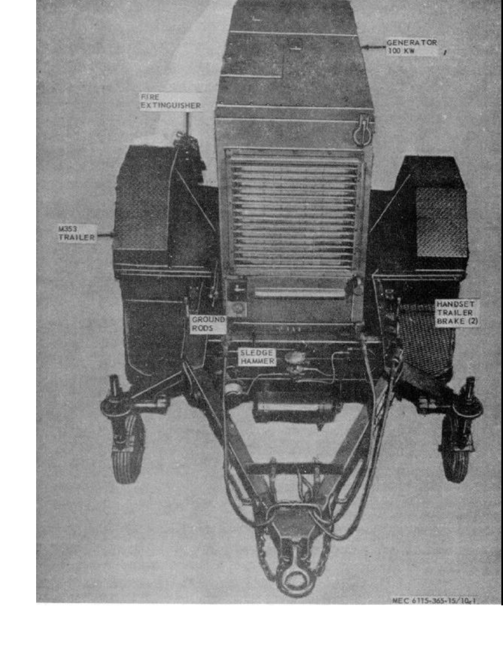
MEC 6115-365-15/10-1
MEC 6115-365-15/10 1
TM 5-6115-365-15
Figure 10-1. Generator Set PU-495/G.
10-2
ILLUSTSOURCE
CODES
LINE
NO.
GUIDE QTY(S) PER MAJ EQUIPS
DESCRIPTION
15 DAYS MAINTENANCE
MANUFACTURER’S ORGANIZATION DS GS
MAINT
DEPOT
MATERIAL
SOURCE
MAINT
RECOVERABILITY
FEDERAL
STOCK
NUMBER
CODE PART NO.
UNIT OF ISSUE
QTY INCORPORATED
IN UIT
1-5 6-10 100 EQUIPMENTS
FIGURE NO.
ITEM NO.
TM 5-6115-365-15
Section II. REPAIR PARTS LIST
0001 SECTION II - REPAIR PARTS LIST
0002 GROUP 15 - FRAME, TOWING ATTACHMENTS,
AND DRAWBARS
0003 1501 - FRAME ASSEMBLY
0004 X2O BRACKET, MOUNTING, GROUND ROD 97403 13214E1288 1* * * * *
0005 X2O BRACKET 14850 A116-726 1* * * * *
0006 X2O HOLDER 14850 D116-125Y 1* * * * *
0007 X2O SCREW, CAP, HEXAGON HEAD: GROUND ROD MTG 96906 MS90725-33 2* * * * *
0008 O5310-081-4219 WASHER, FLAT: GROUND ROD MTG 96906 MS27183-12 2* * * * *
0009 O5310-984-3806 NUT, SELF-LOCKING, HEXAGON: GROUND ROD
MOUNTING 96906 MS51922-9 2* * * * *
0010 X2O BRACKET, DOUBLE ANGLE, SLEDGE HAMMER 97403 13214E1214 1* * * * *
0011 X2O BRACKET 14850 D116-741X 1* * * *
0012 X2O HOLDER 14850 D116-741X 1* * * * *
0013 X2O 5340-914-2578 CLIP, SPRING TENSION: SLEDGE HAMMER
BRACKET 97403 1321E11213-1 1* * * * *
0014 O5310-068-1251 NUT, SELF-LOCKING, HEXAGON: SLEDGE HAMMER
BRACKET MTG 96906 MS51922-1 3* * * * *
0015 O5305-068-0502 SCREW, CAP, HEXAGON HEAD: SLEDGE HAMMER
BRACKET MTG 96906 MS90725-6 3* * * * *
0016 O5310-809-4858 WASHER, FLAT: SLEDGE HAMMER BR ACKET 96906 MS27183-10 3* * * * *
0017 X2O 5307-722-2437 STUD, CONTINUOUS THREAD: GROUND WIRE 97430 13214E1223 1* * * * *
0018 O5310-720-0530 NUT, PLAIN, HEXAGON: GROUND 96906 MS35691-6 3* * * * *
0019 O5310-543-4717 NUT, PLAIN, WING: GROUND STUD 96906 MS35425-28 1* * * * *
0020 O5310-900-6323 WASHER, FLAT: GROUND STUD 96906 MS45901-7 4* * * * *
0021 X2O WASHER, LOCK, FLAT, EXTERNAL TOOTH:
GROUND STUD, BRONZE 3/8 IN. ID 96906 MS35335-91 1* * * * *
0022 X2O 5975-878-3791 ROD, GROUND 1*** * *
0023 GROUP 18 - BODY, CAB, HOOD AND HULL
0024 1808 - STOWAGE RACKS, BOXES, STRAPS,
CARRYING CASES, CABLE REELS,
HOSE REELS, ETC.
0025 X2O 6115-705-460 BOX, ACCESSORY, STOWAGE 97403 13214E1273 1* * * * *
0026 O5310-984-38D6 NUT, SELF-LOCKING, HEXAGON: ACCESSORY
BOX MTG 96906 MS51922-9 2*** * *
0027 5306-225-8499 BOLT, MACHINE: ACCESSORY BOX MTG 96906 MS90725-34 2* * * * *
0028 O5310-081-4219 WASHER, FLAT: ACCESSORY BOX MTG 96906 MS27183-12 2* * * * *
0029 1810 - CARGO BODY
(DUMP, STAKE, AND PLATFORM)
0030 X2FR 2330-542-2831 CHASSIS, TRAILER 97403 13214E1314 1* * * * *
0031 GROUP 22 - BODY CHASSIS OR HULL, AND
ACCESSORY ITEMS
0032 2202 - ACCESSORY ITEMS
0033 X2O 7240-177-6159 SPOUT, CAN, FLEXIBLE 96906 MILS1235 1* * * * *
0034 X2O 2910-066-1235 ADAPTER ASSEMBLY, FUEL DRUM 97403 13211E7541 1* * * * *
0035 2210 - DATA PLATES AND INSTRUCTION
HOLDERS
0036 X2F 9905-577-4219 PLATE, DATA: CORPS or ENGINEERS, TYPE A 97403 13212E1399 1* * *
0031 F5310-050-2950 WASHER, LOCK: DATA PLATE MTG 96906 MS35337-77 4* * *
0030 F5305-058-2088 SCREW, TAPPING, THREAD FORMING: DATA
PLATE MTG 4* * *
0039 GROUP 40 - ELECTRIC MOTORS AND GENERATORS
0040 4000 - MAJOR ASSEMBLAGE
0041 X2FR 6115-752-1588 GENERATOR SET, DIESEL ENGINE: 100 KW 1* * *
0042 F5306-180-0094 BOLT, MACHINE: GENERATOR MTG 88044 AN10-14A 4* * *
0043 F5310-269-4044 NUT, SELF-LOCKING, HEXAGON: GENERATOR
MOUNTING 96906 MS51922-49 4* * *
0044 X2F WASHER, BEVELED: GENERATOR MTG 97403 13206E4482-3 4* * *
0045 F5310-823-8803 WASHER, FLAT: GENERATOR MTG 96906 MS27183-21 4* * *
0046 4019 - RADIO INTERFERENCE SUPPRESSION
0047 MOWIRE, ELECTRICAL: GENERATOR TO GROUND
STUD 81349 QQW343 1
MANUFACTURE FROM:
0048 PO6145-857-6903 WIRE, ELECTRICAL (LENGTH AS REQUIRED) FT SEE GRP 9501
10-3
ILLUSTSOURCE
CODES
LINE
NO.
GUIDE QTY(S) PER MAJ EQUIPS
DESCRIPTION
15 DAYS MAINTENANCE
MANUFACTURER’S ORGANIZATION DS GS
MAINT
DEPOT
MATERIAL
SOURCE
MAINT
RECOVERABILITY
FEDERAL
STOCK
NUMBER
CODE PART NO.
UNIT OF ISSUE
QTY INCORPORATED
IN UIT
1-5 6-10 100 EQUIPMENTS
FIGURE NO.
ITEM NO.
TM 5-6115-365-15
0049 GROUP 76 - FIRE FIGHTING EQUIPMENT
COMPONENTS
0050 7603 - FIRE EXTINGUISHERS
0051 PO4210-270-4512 EXTINGUISHER, FIRE 1* * * * *
0052 X2O 4210-268-729 BRACKET, FIRE EXTINGUISHER 97403 13214E1235 1* * * * *
0053 O5306-225-8497 SCREW, CAP, HEXAGON HEAD: BRACKET MTG 96906 MS90725-32 4* * * * *
5310-081-4219 WASHER, FLAT: BRACKET PT 96906 MS27183-12 4* * * * *
0055 O5310-984-3806 NUT, SELF-LOCKING, HEXAGON: BRACKET MTG 96906 MS51922-9 4* * * * *
0056 GROUP 95 - GENERAL USE STANDARDIZED
PARTS
0057 9501 - BULK MATERIAL
0058 PO6145-857-6903 WIRE, ELECTRICAL FT * * * * *
10-4

TM 5-6115-365-15
CHAPTER 11
GENERATOR SETS PU-332/G AND PU-332A/G
Section I. DESCRIPTION AND DATA
11-1. Description
a. General. A 10-kw, 60-cycle, ac generator
directly coupled to a 4-cylinder, 20-hp, water or aircooled
gasoline engine, mounted on a 2-wheeled, box type
steel body, 3/4-ton capacity, model M101 trailer,
comprise the general purpose Generator Sets PU-332/G
and PU-332A/G.
b. Difference in Models. The PU-332A/G unit has
a Military Standard, model SF-10-MD, aircooled, 10-kw,
60-cycle, 120/208-volt, 3-wire generator powered by a
Military Standard gasoline engine model 4A0482. The
PU-332/G unit does not have a Military Standard
generator and engine.
c. Generator. For description and further
generator information refer to applicable technical
manual, as shown on nameplates or in DA Pam 310-4,
for Military Standard model SF-10-MD and Bogue
Electric Company model 5660.
d. Power Units. For description and further
information for sets equipped with PE-95 power units
refer to applicable technical manuals, as shown on
generator set nameplates or in DA Pam 310-4.
e. Engines. Applicable technical manuals, as
shown on nameplates or in DA Pam 310-4, contain
descriptive and additional information about sets
furnished with model 4A084-11 Military Standard
engines. For additional information about sets equipped
with Willys Overland model CJ-3a engines refer to
applicable technical manual, as shown on nameplate or
in DA Pam 310-4.
f. Trailer. For further trailer information refer to
applicable technical manual, as shown on trailer
nameplate or in DA Pam 310-4.
g. Lubrication. Lubricate the trailer as outlined in
applicable lubrication order, as shown in DA Pam 310-4.
Applicable lubrication order, as shown in DA Pam 310-
4, contains instructions for lubricating the Military
Standard engines model 4A084-11. Lubricate power
unit PE-95 as instructed in applicable lubrication order,
as shown in DA Pam 310-4.
11-1
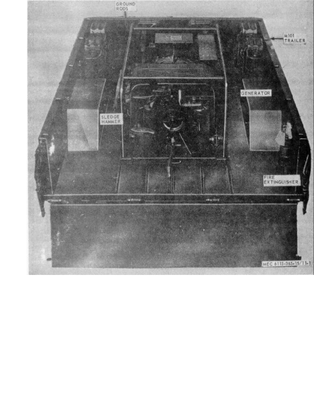
MEC 6115-365-15/11-1
TM 5-6115-365-15
Figure 11-1. Generator Set PU-332A/G.
11-2
ILLUSTSOURCE
CODES
LINE
NO.
GUIDE QTY(S) PER MAJ EQUIPS
DESCRIPTION
15 DAYS MAINTENANCE
MANUFACTURER’S ORGANIZATION DS GS
MAINT
DEPOT
MATERIAL
SOURCE
MAINT
RECOVERABILITY
FEDERAL
STOCK
NUMBER
CODE PART NO.
UNIT OF ISSUE
QTY INCORPORATED
IN UIT
1-5 6-10 100 EQUIPMENTS
FIGURE NO.
ITEM NO.
TM 5-6115-365-15
Section II. REPAIR PARTS LIST
0002 GROUP 01 – ENGINE
0003 0106 - ENGINE LUBRICATION SYSTEM
0004 X2O 4730-278-3888 REDUCER BUSHING: 3/4-14 NPTF EXTERNAL
THREAD X 1/2-14 NPTF INTERNAL THREAD,
OIL DRAIN 81343 SAEJ530 1* * * * *
0005 X2O 4720-91-61422 HOSE, OIL DRAIN 97403 13211E4918 1* * * * * 11-22
0006 O4730-766-7908 7908 UNION, FLARED TUBE, BULKHEAD: OIL DRAIN 08044 AN832-10 1* * * * *
0007 O5310-059-6372 WASHER, LOCK: OIL DRAIN HOSE UNION 96906 MS5337-52 1* * * * *
0008 O5310-282-7822 NUT, UNION: OIL DRAIN HOSE 88044 AN924-10 1* * * * *
0009 GROUP 04 - EXHAUST SYSTEM
0010 0401 - MUFFLER AND PIPES
0011 X2O 6115-914-0258 HOSE ASSEMBLY, METAL 97403 13212E3620 1* * * * *
0012 X2O CLAMP, EXHAUST TUBE SECURING 97403 13213E3622 1* * * * *
0013 O5310-209-5306 WASHER, LOCK 96906 MS35337-24 1* * * * *
0014 O5310-012-0614 NUT, PLAIN, HEXAGON 96906 MS35650-102 1* * * * *
0015 O5305-043-6755 SCREW, MACHINE 96906 MS35226-68 1* * * * *
0016 O5310-550-0777 NUT, PLAIN, HEXAGON: HOOK 96906 MS35690-402 2* * * * *
0017 GROUP 15 - FRAME, TOWING ATTACHMENTS,
AND DRAWBARS
0018 1501 - FRAME ASSEMBLY
0019 X2O 2510-706-4504 BRACKET ASSEMBLY, FUEL CAN 97403 13214E1203 6* * * * *
0020 X2O HOOK, DRIP -AIL: STRAP 97403 13212E3616 6* * * * *
0021 X2O FASTENER 97403 13214E1205 6* * * * *
0022 X2O BUCKLE 96906 MS51940-7 12 * * * * *
0023 MOSTRAP: TOP 97403 13214E1203-2 6
MANUFACTURE FROM:
0024 PO8305-267-3009 WEBBING, NYLON 06716 1403 FT SEE GRP 9501
(30 IN REQUIRED FOR EACH STRAP)
0025 MOSTRAP: BOTTOM 97403 13214E1203-3 6
MANUFACTURE FROM:
0026 PO8305-267-3009 WEBBING, NYLON 06716 1403 FT SEE GRP 9501
(18 IN. REQUIRED FOR EACH STRAP)
0027 X2O BRACKET 97403 13214E1204 6* * * * *
0028 X2O SCREW, CAP, HEXAGON HEAD: FUEL CAN
BRACKET MTD, 3/8-16 X 7/8 IN. LG 96906 MS90725-59 24 * * * * *
0029 O5310-809-4061 WASHER, FLAT: FUEL CAN BRACKET MTG 96906 MS27183-15 24 * * * * *
0030 O5310-087-4652 NUT, SELF-LOCKING, HEXAGON: FUEL. CAN
BRACKET MTG 96906 MS51922-17 24 * * * * *
0031 X2O LOOP, STRAP FASTENER: FUEL CAN 96906 MS51939-2 4* * * * *
0032 O5305-984-6211 SCREW, MACHINE: LOOP MTG 96906 MS35206-264 8* * * * *
0033 O5310-0o9-8546 WASHER, FLAT: LOOP MTG 96906 MS27183-8 8* * * * *
0034 O5310-167-0662 WASHER, LOCK: LOOP MTG 96906 MS35337-43 8* * * * *
0035 O5310-102-0361 NUT, PLAIN, HEXAGON: LOOP MTG 96906 MS35649-102 8* * * * *
0036 O5310-984-3806 NUT, SELF-LOCKING, HEXAGON: ADAPTER
HOLDER MTG 96906 MS51922-9 4* * * * *
0037 X2O 6115-016-2362 HOLDER: FUEL DRUM ADAPTER EXTENSION 97403 13211E4889-1 4* * * * *
0038 O5305-889-3000 SCREW, MACHINE: EXTENSION HOLDER MTG 96906 MS35206-230 8* * * * *
0039 O5310-082-1404 WASHER, FLAT: EXTENSION HOLDER MTG 96906 MS27183-6 8* * * * *
0040 O5310-013-1181 WASHER, LOCK: EXTENSION HOLDER MTG 96906 MS35337-22 8* * * * *
0041 O5310-062-0912 NUT, PLAIN, HEXAGON: EXTENSION HOLDER
MOUNTING 96906 MS35649-64 8* * * * *
0042 X2O 7240-920-5327 HOLDER, SPOUT 97403 13212E3553-1 2* * * * *
0043 O5306-225-8497 BOLT, MACHINE: ADAPTER HOLDER MTD,
5/16-18 X 3/4 IN. LD 96906 MS90725-32 4* * * * *
0044 O5310-081-4219 WASHER, FLAT: ADAPTER HOLDER MTD 96906 MS27183-12 8* * * * *
0045 X2O BRACKET, DOUBLE ANGLE 97403 13214E1214 1* * * * * 11-2 3
0046 X2O BRACKET 97403 13214E1215 1* * * * *
0047 O5310-012-6177 NUT, PLAIN, WING 96906 MS35425-39 2* * * * *
0048 OPLATE, HOLD DOWN 97403 13214E1216 1* * * * *
0049 O5310-012-0392 WASHER, FLAT 96906 MS27183-10 2* * * * *
0050 O5310-043-5862 WASHER, LOCK 96906 MS35337-82 2* * * * *
0051 X2O 5340-914-2578 CLIP, SPRING TENSION: SLEDGE HAMMER
HANDLE 97403 13214E1213-1 1* * * * *
0052 O5305-068-0502 SCREW, CAP, HEXAGON HEAD: SLEDGE HAMMER
BRACKET AND SPRING CLIP MTG 96906 MS90725-6 3* * * * *
0053 O5310-809-4058 WASHER, FLAT: SLEDGE HAMMER BRACKET,
SPRING CLIP AND AROUND ROD CLAMP MTG 96906 MS27183-10 10 * * * * *
11-3
ILLUSTSOURCE
CODES
LINE
NO.
GUIDE QTY(S) PER MAJ EQUIPS
DESCRIPTION
15 DAYS MAINTENANCE
MANUFACTURER’S ORGANIZATION DS GS
MAINT
DEPOT
MATERIAL
SOURCE
MAINT
RECOVERABILITY
FEDERAL
STOCK
NUMBER
CODE PART NO.
UNIT OF ISSUE
QTY INCORPORATED
IN UIT
1-5 6-10 100 EQUIPMENTS
FIGURE NO.
ITEM NO.
TM 5-6115-365-15
0054 O5310-088-1251 NUT, SELF-LOCKING, HEXAGONS SLEDGE HAMMER
BRACKET SPRING CLIP AND GROUND ROD
CLAMP MTG 96906 MS51922-1 7* * * * *
0055 X2O STRAP, RETAINING 97403 13212E3617 2* * * * *
0056 O5305-958-5246 SCREW, MACHINES: GROUND ROD CLAMP MTG 96906 MS35190-289 4* * * * *
0057 O5310-526-2559 CLAMP, CUSHIONED: GROUND WIRE 96906 MS21919F2 2* * * * *
0058 O5305-984-6211 SCREW, MACHINE GROUND WlRE CLAMP MTG 96906 MS35206-264 2* * * * *
0059 5310-809-8546 WASHER, FLATS GROUND WIRE CLAMP MTG 96906 M627183-8 4* * * * *
0060 O5310-167-0662 WASHER, LOCK: GROUND WIRE CLAMP MTG 96906 M35337-13 2* * * * *
0061 O5310-012-0361 NUT, PLAIN, HEXAGON GROUND WIRE CLAMP
MOUNTING 96906 MS35649-102 2* * * * *
0062 X2O 5307-722-9437 STUD, CONTINUOUS THREAD: GROUND 97403 13214E1223 1* * * * *
0063 X2O WASHER, LOCK: BRONZE EXTERNAL TOOTH
3/8 IN., GROUND STUD 96906 MS35335-91 2* * * * *
0064 O5310-720-8531 NUT, PLAIN, HEXAGON: BRAGS, GROUND STUD
TO TRAILER 96906 MS35691-611 2* * * * *
0065 X2O 5310-900-6323 WASHER, FLAT: BRASS, GROUND STUD,
.390 ID 96906 MS45901-7 4* * * * *
0066 O5310-720-8528 NUT, PLAIN, HEXAGONS BRASS, GROUND STUD 96906 MS35690-611 2* * * * *
0067 O5310-543-4717 NUT, PLAIN, WING: BRASS, GROUND STUD 96906 MS35425-28 1* * * * *
0068 1507 - LANDING GEAR, LEVELING JACKS
(MECHANICAL OR HYDRAULIC)
0069 X2O 2590-318-6691 LEG ASSEMBLY, TRAILER PROP 97403 13214E1206 1* * * * *
0070 X2O BRACKET 97403 13214E1207 1* * * * *
0071 X2O LEG ASSEMBLY, UPPER 97403 13214E1208 1* * * * *
0072 X2O CHAIN: PIN RETAINING 97403 13214E1208- 1* * * * *
0073 X2O PIN 97403 13214E1208- 1* * * * *
0074 X2O LEG, BASE 97403 13214E1212 1* * * * *
0075 SHAFT 97403 13214E1209 1* * * * *
0076 O4730-172-0049 FITTING, LUBRICATION 96906 MS15006-1 1* * * * *
0077 X2O SCREW 97403 13214E1210 1* * * * *
0078 X2O NUT 97403 13214E1211
0079 X2O RIVET, SOLID, UNIVERSAL HEAD: 1/4 IN.
DIA, 2 IN. LG 96906 MS20613-8P32 1* * * * *
0080 X2O PIN, COTTER: 1/8 IN. DIA, 3/4 IN. LG 96906 MS24665-351 1* * * * *
0081 O5305-269-3213 SCREW, CAP, HEXAGON HEAD: LEG ASSEMBLY
TO TRAILER, 3/8-16 X 1 1/4 IN LG 96906 MS20613-8P62 3* * * * *
0082 O5310-809-4061 WASHER, FLAT: LEG ASSEMBLY TO TRAILER 96906 MS27183-15 6* * * * *
0083 O5310-087-4652 NUT, SELF-LOCKING, HEXAGON: LEG
ASSEMBLY TO TRAILER 96906 MS51922-17 3* * * * *
0084 GROUP 18 - BODY, CAB, HOOD AND HULL
0085 1801 - BODY, CAB, HOOD, HILL ASSEMBLIES
0086 X2F 2330-898-6779 TRAILER M101A1 97403 13214E1225-1 1* * * * *
0087 GROUP 22 - BODY CHASSIS OR HULL, AND
ACCESSORY ITEMS
0088 2202 - ACCESSORY ITEMS
0089 X2O 2910-166-235 ADAPTER ASSEMBLY, FUEL TANK 97403 13211E7541 2* * * * *
0090 X2O PIPE 97403 13211E7543 2* * * * *
0091 X2O WASHER, BRASS 97103 13211E7544 2* * * * *
0092 X2O SCREW, SHOULDER 97403 13211E7545 4* * * * *
0093 X2O RING, SEALING 97403 13211E7546 2* * * * *
0094 X2O WASHER, RUBBER 97403 13211E7547 2* * * * *
0095 X2O HEAD 97403 13211E7548 2* * * * *
0096 X2O WASHER, STEEL 97403 13200E6361 2* * * * *
0097 X2O CLAMP 97403 13200E6363 2* * * * *
0098 O5310-209-1239 WASHER, LOCK: SHOULDER SCREW 96906 1635335-60 1* * * * *
0099 X2O PIPE, EXTENSION 97403 13211E7542 2* * * * *
0100 O4730-278-3357 ADAPTER, STRAIGHT: HOSE 2* * * * *
0101 X2O 7240-222-3088 CAN, GASOLINE: MILITARY, 5 GAL 6* * * * *
0102 2210 - DATA PLATES AND INSTRUCTION
HOLDERS
0103 X2F 9905-577-4219 PLATE, DATA: CORPS or ENGINEER, TYPE A 97403 13212E3599 1* * *
0104 F5310-058-2950 WASHER, LOCK: DATA PLATE MTG 96906 MS35337-77 4* * *
0105 F5320-058-2088 SCREW, TAPPING, THREAD FORMING: DATA
PLATE NYC, No. 2-32 X 1/4 IN. LG 96906 MS24622-3 4* * *
11-4
ILLUSTSOURCE
CODES
LINE
NO.
GUIDE QTY(S) PER MAJ EQUIPS
DESCRIPTION
15 DAYS MAINTENANCE
MANUFACTURER’S ORGANIZATION DS GS
MAINT
DEPOT
MATERIAL
SOURCE
MAINT
RECOVERABILITY
FEDERAL
STOCK
NUMBER
CODE PART NO.
UNIT OF ISSUE
QTY INCORPORATED
IN UIT
1-5 6-10 100 EQUIPMENTS
FIGURE NO.
ITEM NO.
TM 5-6115-365-15
0106 GROUP 40 - ELECTRIC MOTORS AND GENERATORS
0107 4000 - MAJOR ASSEMBLAGE
0108 X2FR 6115-075-1641 GENERATOR SET, GASOLINE ENGINE DRIVEN:
10 KW MIL-G-52280 1* * * 11-25
0109 F5305-724-5910 SCREW, CAP, HEXAGON HEAD: generator
frame to trailer, 5/8-11 X 1 1/2 in. Ig 96906 MS90725-162 4* * *
0110 F5310-823-8803 WASHER, FLAT: generator frame to
trailer, .656 in. 96906 MS27183-21 8* * *
0111 X2F SPACER, SHIM 97403 13214E1222-3 4* * *
0112 X2F 5310-269-4040 NUT, SELF-LOCKING, HEXAGON: generator
frame to trailer, 5/8-11 96906 MS51922-49 4* * *
0113 4019 - RADIO INTERFERENCE SUPPRESSION
0114 MOWIRE, ELECTRICAL: generator to ground stud 1* * *
MANUFACTURE FROM:
0115 PO6145-299-6188 WIRE (Length as required) FT SEE GRP 9501
0116 GROUP 76 - FIRE FIGHTING EQUIPMENT
COMPONENTS
0117 7603 - FIRE EXTINGUISHERS
0118 P1O 4210-555-8837 EXTINGUISHER, FIRE 1* * * * * 11-24
0119 O5305-068-0502 SCREW, CAP, HEXAGON HEAD: extinguisher
mtg, 1/4-20 x 3/4 in. Ig 96906 MS90725-6 4* * * * *
0120 O5310-809-4058 WASHER, FLAT: extinguisher mtg 96906 MS27183-10 8* * * * *
0121 O5310-088-1251 NUT, SELF-LOCKING, HEXAGON: extinguisher
mounting 96906 MS51922-1 4* * * * *
0122 GROUP 95 - GENERAL USE STANDARDIZED
PARTS
0123 9501 - BULK MATERIAL
0124 PO8305-267-3009 WEBBING, NYLON 06716 1403 FT * * * * *
0125 PO6145-299-6188 WIRE, ELECTRICAL FT * * * * *
Change 8 11-5
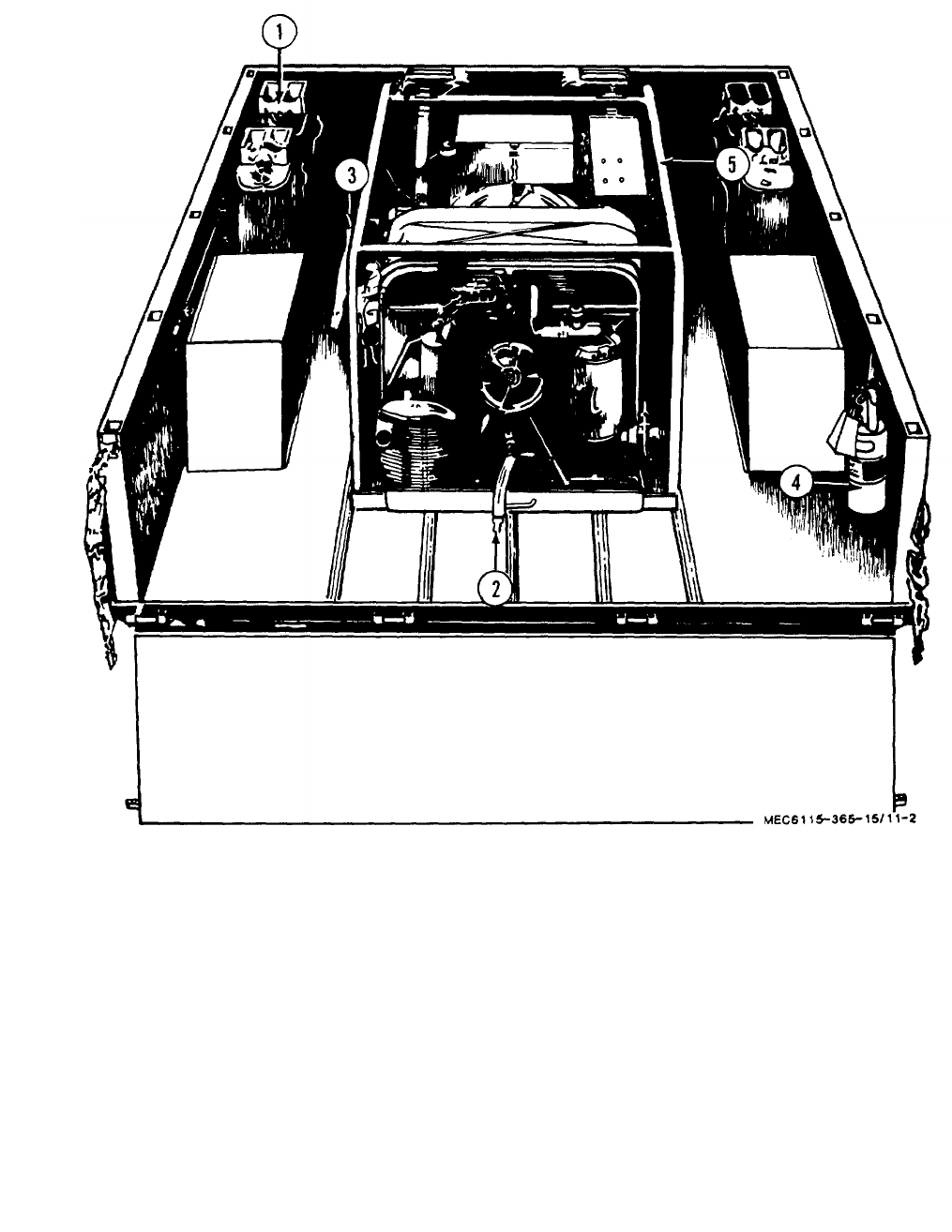
MEC6115-365-15/11-2
TM 5-4115-365-15
1Can 4Extinguisher
2Hose 5Generator
3Bracket
Figure 11-2. Accessories.
11-6

TM 5-6115-365-15
C3
CHAPTER 12
GENERATOR SETS PU-564A/G, FSN 6115-738-6341
AND PU-564B/G, FSN 6115-179-2789
Section I. DESCRIPTION AND DATA
12-1. Description
a. General. The trailer mounted generator sets,
PU-564A/G and PU-564B/G, consist of a 10 KW, DOD
Model MEP-018A generator set mounted on a modified
1-1/2ton, 2-wheel cargo trailer, Model M105A1 or
M105A2 (PU564A/G), or a Model 103A3 (PU564B/G).
b. Generator. The generator is powered by a
directly-coupled 4-cylinder, air-cooled, 20-hp, Military
Standard Model 4A084 gasoline engine. For description
and generator operation and maintenance, refer to
TM 5-6115-275-15.
c. Engines. For description and engine
maintenance information, refer to TM 5-2805-259-14.
d. Trailers. For description and maintenance of the
trailers, refer to TM 9-233-0213-14.
e. Lubrication. For lubrication of the engine refer to
LO 5-2805-259-12. The trailer lubrication information is
contained in LO 9-2330-213-12.
12-1
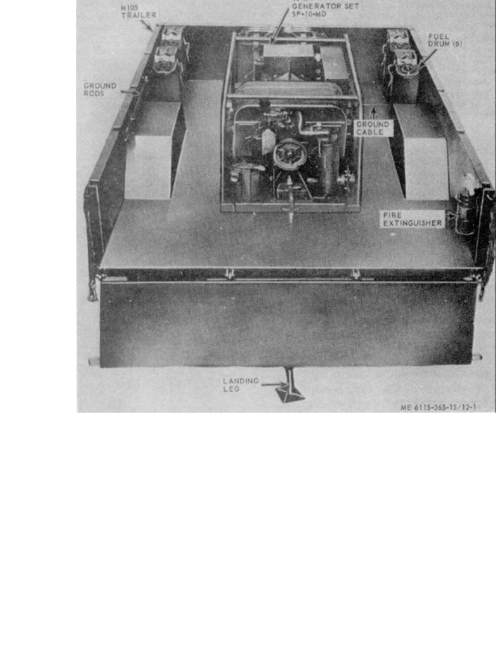
ME 6115-365-15/12-1
TM 5-6115-365-15
C3
Figure 12-1. Generator set, PU-564A/G.
12-2
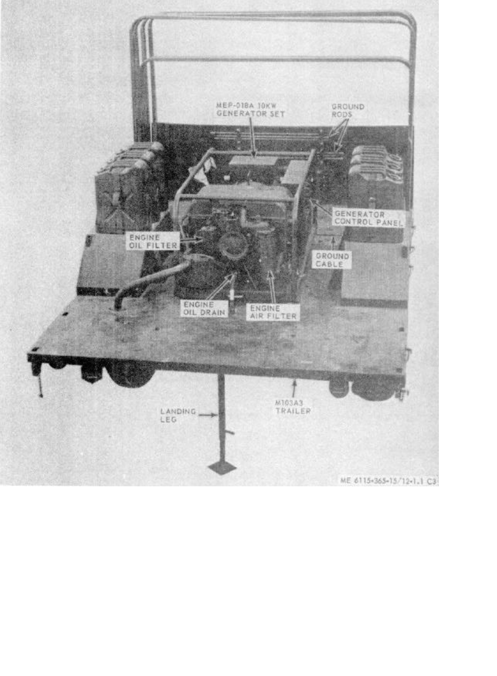
ME 6115-365-15/12-1.1 C3
TM 5-6115-365-15
C3
Figure 12-1.1. Generator set, PU564B/G.
12-2.1
ILLUSTSOURCE
CODES
LINE
NO.
GUIDE QTY(S) PER MAJ EQUIPS
DESCRIPTION
15 DAYS MAINTENANCE
MANUFACTURER’S ORGANIZATION DS GS
MAINT
DEPOT
MATERIAL
SOURCE
MAINT
RECOVERABILITY
FEDERAL
STOCK
NUMBER
CODE PART NO.
UNIT OF ISSUE
QTY INCORPORATED
IN UIT
1-5 6-10 100 EQUIPMENTS
FIGURE NO.
ITEM NO.
TM 5-6115-365-15
Section II. REPAIR PARTS LIST
0002 GROUP 01 - ENGINE
0003 0106 - ENGINE LUBRICATION SYSTEM
0004 X2O 4730-278-3888 BUSHING, PIPE: OIL DRAIN 81343 SAEJ530 1* * * * *
0005 X2O 4720-913-6422 HOSE, ASSEMBLY, RUBBER 97403 13211E4918 1* * * * * 12-2 5
0006 O4730-277-6440 NIPPLE, TUBE: OIL DRAIN 88044 AN832-10 1* * * * *
0007 O5310-059-6372 WASHER, LOCK: OIL DRAIN HOSE UNION 96906 S3537-52 1* * * * *
0008 O5310-202-7822 NUT, PLAIN, HEXAGON: OIL DRAIN HOSE 88044 MS24400-10 1* * * * *
0009 GROUP 04 - EXHAUST SYSTEM
0010 0401 - MUFFLER AND PIPES
0011 X2O 6115-914-0258 HOSE ASSEMBLY, METAL 97403 13212E3620 1* * * * *
0012 X2O CLAMP, EXHAUST TUBE SECURING 97403 13212E3622 1* * * * *
0013 O5310-209-5306 WASHER, LOCK 96906 MS35337-24 1* * * * *
0014 O5310-012-0614 NUT, PLAIN, HEXAGON 96906 MS35650-102 1* * * * *
0015 O5305-043-6755 SCREW, MACHINE 96906 MS35226-68 1* * * * *
0016 O5310-550-0777 NUT, PLAIN 96906 MS35690-402 1* * * * *
0017 GROUP 05 - COOLING SYSTEM
0018 0501 - RADIATOR, EVAPORATIVE COOLER,
OR HEAT EXCHANGER
0019 X2O 2510-706-4504 BRACKET, LIQUID CONTAINER 97403 13214E1203 6* * * * *
0020 X2O HOOK, DRIP RAIL: STRAP 97403 13212E3616 6* * * * *
0021 X2O FASTENER 97403 13214E1205 6* * * * *
0022 X2O BUCKLE 96906 MS51940-7 12 * * * * *
0023 MOSTRAP: TOP 97403 13214E1203-2 6* * * * *
MANUFACTURE FROM-
0024 PO8305-267-3009 WEBBING, NYLON 06716 1403 FT SEE GRP 9501
(30 IN. REQUIRED FOR EACH STRAP)
0025 MOSTRAP: BOTTOM 97403 13214E1203-3 6* * * * *
MANUFACTURE FROM:
0026 PO305-267-3o009 WEBBING, NYLON 06716 1403 FT SEE GRP 9501
(18 IN. REQUIRED FOR EACH STRAP)
0027 X2O BRACKET 97403 13214E1204 6* * * * *
0028 O5305-269-3210 SCREW, CAP, HEXAGON HEAD: FUEL CAN
BRACKET MT 3/8-16 x 7/8 IN. LG 96906 MS90725-59 24 * * * * *
0029 O5310-809-4061 WASHER, FLAT: FUEL CAN BRACKET MTG 96906 MS27183-15 24 * * * * *
0030 O5310-087-4652 NUT, SELF LOCKING, HEXAGON: FUEL CAN
BRACKET MTG 96906 MS51922-17 24 * * * * *
0031 X2O LOOP, STRAP FASTENER: FUEL CAN 96906 MS51939-2 4* * * * *
0032 O5305-984-6211 SCREW, MACHINE LOOP MTG 96906 MS35206-26 8* * * * *
0033 O5310-809-8546 WASHER, FLAT: LOOP .MTG 96906 MS27183-8 8* * * * *
0034 O5310-167-0662 WASHER, LOCK: LOOP MTG 96906 MS35337-13 8* * * * *
0035 O5310-102-0361 NUT, PLAIN, HEXAGON: LOOP MTG 96906 MS35649-102 8***'* *
0036 X2O 6115-016-2362 HOLDER, COMPONENT: FUEL DRUM ADAPTER,
EXTENSION 97403 13211E4889-1 4* * * * *
0037 5305-889-3000 SCREW, MACHINE: EXTENSION HOLDER MTG 96906 MS35206-230 8* * * * *
0038 O5310-082-1404 WASHER, FLAT: EXTENSION HOLDER MTG 96906 MS27183-6 8* * * * *
0039 O5310-596-7674 WASHER, LOCK: EXTENSION HOLDER MTG 96906 MS35337-22 8* * * * *
0040 5310-062-0912 NUT, PLAIN, HEXAGON: EXTENSION HOLDER
MOUNTING 96906 MS35649-64 8* * * * *
0041 X2O 7240-920-5327 HOLDER, SPOUT: FUEL DRUM ADAPTER 97403 13212E3553-1 2* * * * *
0042 O5306-225-8497 BOLT, MACHINE: ADAPTER HOLDER MTG
5/16-18 X 3/4 IN. LO 96906 MS90725-32 4* * * * *
0043 O5310-0814219 WASHER, FLAT: ADAPTER HOLDER MTG 96906 MS27183-12 8* * * * *
0044 5310-984-3806NUT, SELF-LOCKING, HEXAGON: ADAPTER
HOLDER MTG 96906 MS5122-9 4* * * * *
0045 X2O BRACKET ASSEMBLY, SLEDGE HAMMER 97403 13214E1214 1* * * * *
0046 X2O BRACKET 97403 13214E1215 1* * * * *
0047 O5310-012-6177 NUT, PLAIN, WING 96906 MS35425-39 2* * * * *
0048 X2O PLATE, HOLD DOWN 97403 13214E1216 1* * * * *
0049 O5310-012-0392 WASHER, FLAT 96906 MS27183-10 2* * * * *
0050 O5310-043-5862 WASHER, LOCK 96906 MS35337-82 2* * * * *
0051 X2O 5340-914-2578 CLIP, SPRING TENSION: SLEDGE HAMMER
HANDLE 97403 13214E1213-1 1* * * * *
0052 O5305-068-0502 SCREW, CAP, HEXAGON HEAD: SLEDGE HAMMER
BRACKET AND SPRING CLIP MTG 96906 MS90725-6 3* * * * *
12-3

ILLUSTSOURCE
CODES
LINE
NO.
GUIDE QTY(S) PER MAJ EQUIPS
DESCRIPTION
15 DAYS MAINTENANCE
MANUFACTURER’S ORGANIZATION DS GS
MAINT
DEPOT
MATERIAL
SOURCE
MAINT
RECOVERABILITY
FEDERAL
STOCK
NUMBER
CODE PART NO.
UNIT OF ISSUE
QTY INCORPORATED
IN UIT
1-5 6-10 100 EQUIPMENTS
FIGURE NO.
ITEM NO.
TM 5-6115-365-15
0053 O53103-809458 WASHER, FLAT: SLEDGE HAMMER BRACKET,
SPRING CLIP AND GROUND PO CLAMP MTG 96906 MS27183-10 10 * * * * *
0054 O5310-088-1251 NUT, SELF-LOCKING HEXAGON SLEDGE
HAMMER BRACKET, SPRING CLIP AND GROUND
ROD CLAMP MTG 96906 MS51922-1 7* * * * *
0055 XAO CLAMP, GROUND ROD 97403 13212E3617 2* * * * * 12-2 2
0056 O5305-958-5246 SCREW, MACHINE: GROUND ROD CLAMP MTG 96906 MS35190-289 4* * * * *
0057 X2O 5314-526-2559 CLAW, CUSHIONED; GROUND WIRE 96906 MS21919F2 3* * * * *
0058 O5305-984-6211 SCREW, MACHINE; GROUND WIRE CLAMP MTG 96906 MS35206-264 3* * * * *
0059 O5310-809-8546 WASHER, FLAT: GROUND WIRE CLAMP MTG 96906 MS27183-8 6* * * * *
0060 O5310-167-0662 WASHER, LOCK GROUND WIRE CLAMP MTG 96906 MS35337-43 3* * * * *
0061 O5310-012-0361 NUT, PLAIN, HEXAGON: GROUND WIRE CLAMP
MOUNTING 96906 MS35649-102 1* * * * *
0062 X2O 5307-722-9437 STUD CONTINUOS THREAD: AROUND 96906 13214E1223 1* * * * *
0063 X2O WASHER, LOCK: BRONZE, EXTERNAL TOOTH,
3/8 IN., GROUND STUD 96906 MS35335-91 2* * * * *
0064 O5310-835-7478 NUT, PLAIN, HEXAGON BRASS, GROUND STUD
TO TRAILER 96906 MS35691-611 2* * * * *
0065 O5310-900-6323 WASHER, FLAT: BRASS, GROUND STUD 390 to 96906 MS45901-7 2* * * * *
0066 O5310-720-4528 NUT, PLAIN, HEXAGON: BRASS, GROUND STUD 96906 MS35690-611 1* * * * *
0067 O5310-543-4717 NUT, PLAIN, WING: BRASS, GROUND STUD 96906 MS35425-8 1* * * * *
0068 1507 - LANDING GEAR, LEVELING JACKS
(MECHANICAL OR HYDRAULIC)
0069 X2O 2590-318-6691 LEG ASSEMBLY, TRAILER PROP 97403 13214E1206 1* * * * *
0070 X2O BRACKET 97403 13214E1207 1* * * * *
0071 X2O LEG ASSEMBLY, UPPER 97403 13214E1208 1* * * * *
0072 X2O CHAIN PlN RETAINING 97403 13214E1208-6 1* * * * *
0073 X2O PIN 97403 13214E1208-5 1* * * * *
0074 X2O LEG, BASE 97403 13214E1212 1* * * * *
0075 X2O SHAFT 97403 13214E1209 1* * * * *
0076 O4730-172-0049 FITTING, LUBRICATION 97403 MS15006-1 1* * * * *
0077 X2O SCREW 97403 13214E1210 1* * * * *
0078 X2O NUT 97403 13214E1211 1* * * * *
0079 X2O RIVET, SOLID, UNIVERSAL HEAD
1/4 IN DIA 96906 MS20613-8P32 1* * * * *
0080 X2O PIN, COTTER: 1/8 IN DIA, 3/4 IN 96906 MS24665-351 1* * * * *
0081 X2O 5305-269-3213 SCREW, CAP, HEXAGON HEAD LEG ASSEMBLY
TO TRAILER, 3/8-16 X 1 1/4 IN LG 96906 S90725-62 3* * * * *
0082 O5310-809-4061 WASHER, FLAT: LEG ASSEMBLY TO TRAILER 96906 527183-15 6* * * * *
0083 O5310-087-4652 NUT, SELF-LOCKING HEXAGONS LEG ASSEMBLY
TO TRAILER 96906 MS51922-17 3* * * * *
0084 GROUP 18 - BODY, CAB, HOOD AND HULL
0085 1810 - CARGO BODY
(DUMP, STAKE, AND PLATFORM)
0086 X2F 2330-141-8050 TRAILER: M 105 MODIFlED 97403 13214E1221-2 1* * * * *
0087 GROUP 22 - BODY CHASSIS OR HULL, AND
ACCESSORY ITEMS
0088 2202 - ACCESSORY ITEMS
0089 X2O 2910-66-1235 ADAPTER ASSEMBLY, FUEL DRUM 97403 13211E7541 2* * * * *
0090 X2O WASHER, BRASS 97403 13211E7544 2* * * * *
0091 X2O SCREW, SHOULDER 97403 13211E7545 4* * * * *
0092 X2O RING, SEALING 97403 13211E7546 2* * * * *
0093 X2O WASHER, RUBBER 97403 13211E7547 2* * * * *
0094 X2O HEAD 97403 13211E7548 2* * * * *
0095 X2O WASHER, STEEL 97403 13200E6361 2* * * * *
0096 X2O CLAP 97403 13200E6363 2* * * * *
0097 O5310-209-1239 WASHER, LOCK: SHOULDER SCREW 96906 MS35335-60 4* * * * *
0098 X2O PIPE 97403 13211E7543 2* * * * *
0099 X2O PIPE, EXTENSION 97403 13211E7522 2* * * * *
0100 O4730-278-3357ADAPTER, STRAIGHT: HOSE 2* * * * *
0101 X2O 7240-222-3013 CAN, GASOLINE: ,MILITARY, 5 GAL 6* * * * 12-2 1
0102 GROUP 22 - BOY CHASSIS OR HULL, AND
ACCESSORY ITEMS
0103 2210 - DATA PLATES AND INSTRUCTION
HOLDERS
0104 X2F 9905-577-4219 PLATE, DATA: CORPS OF ENGINEERS, TYPE A 97403 13212E3599 1* * *
0105 F5310-058-2950 WASHER, LOCK: DATA PLATE MTG 96906 MS35337-77 4* * *
12-4
ILLUSTSOURCE
CODES
LINE
NO.
GUIDE QTY(S) PER MAJ EQUIPS
DESCRIPTION
15 DAYS MAINTENANCE
MANUFACTURER’S ORGANIZATION DS GS
MAINT
DEPOT
MATERIAL
SOURCE
MAINT
RECOVERABILITY
FEDERAL
STOCK
NUMBER
CODE PART NO.
UNIT OF ISSUE
QTY INCORPORATED
IN UIT
1-5 6-10 100 EQUIPMENTS
FIGURE NO.
ITEM NO.
TM 5-6115-365-15
0106 F5305-058-2088 SCREW, TAPPING, THREAD FORMING: data
plate mtg, No. 2-32 x 1/4. In. Ig 96906 MS24622-3 4* * *
0107 GROUP 40 - ELECTRIC MOTORS AND GENERATORS
0108 4000 - MAJOR ASSEMBLAGE
0109 X2FR 6115-889-1447 GENERATOR. GASOLINE ENGINE DRIVEN: 10 KW 1* * *
0110 X2F 5305-724-5910 SCREW, CAP, HEXAGON HEAD: generator
frame to trailer, 5/8-11 X 11/2 in. Ig 96906 MS90725-162 4* * *
0111 X2F 5310-823-8803 WASHER, FLAT: generator frame to
trailer, .656 in. 96906 MS27183-21 8* * *
0112 X2F SPACER, SHIM 97403 13214E1222-3 4* * *
0113 4019 - RADIO INTERFERENCE SUPPRESSION
0114 MOWIRE, GROUND: generator to ground stud 1
MANUFACTURE FROM:
0115 PO6145-299-6188 WIRE, ELECTRICAL (Length as required) FT SEE GRP 9501
0116 GROUP 76 - FIRE FIGHTING EQUIPMENT
COMPONENTS
0117 7603 - FIRE EXTINGUISHERS
0118 P1O 4210-555-8837 EXTINGUISHER, FIRE 1* * * * * 12-24
0119 X2O 5305-068-0502 SCREW, CAP, HEXAGON HEAD: extinguisher
mtg, 1/4-20 x 3/4 in. Ig 96906 MS90725-6 4* * * * *
0120 O5310-809-4058 WASHER, FLAT: extinguisher mtg 96906 MS27183-10 8* * * * *
0121 O5310-088-1251 NUT, SELF-LOCKING, HEXAGON: extinguisher
mounting 96906 MS51922-1 4* * * * *
0122 GROUP 95 - GENERAL USE STANDARDIZED
PARTS
0123 9501 - BULK MATERIAL
0124 PO8305-267-3009 WEBBING, NYLON 06716 1403 FT * * * * *
0125 PO6145-299-6188 WIRE, ELECTRICAL FT * * * * *
Change 8 12-5
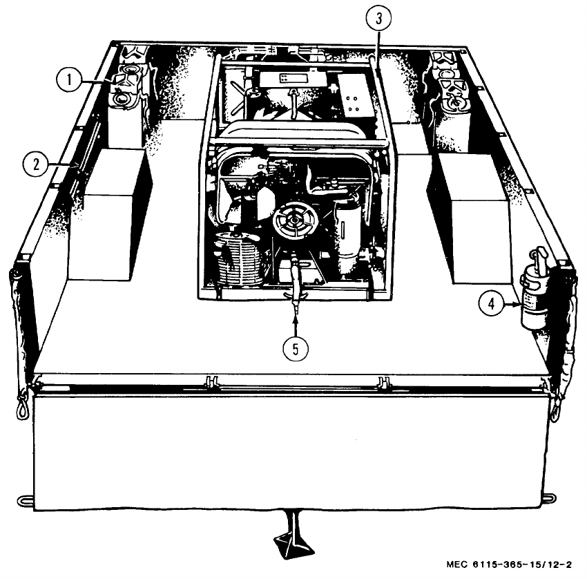
TM 5-6115-365-15
1Can 4Extinguisher
2Clamp 5Hose
3Generator
Figure 12-2. Accessories.
12-6

(1) (2) (3) (4) (5) (6) (7)
FEDERAL DESCRIPTION UNIT QTY 15-DAY ORGANIZATIONAL ILLUS-
SMR STOCK OF INC MAINTENANCE ALW RATION
CODE NUMBER USABLE MEAS IN (a) (b) (c) (d) (a) (b)
ON UNIT FIG ITEM
REF NUMBER & MFG CODE CODE 1-5 6-20 21-50 51-100 NO. NO.
TM 5-6115-365-15
C3
PART II - PU-564B/G
00001 REPAIR PARTS FOR ORGANIZATIONAL MAINTENANCE
00003 GROUP 06 - ELECTRICAL SYSTEM
00004 0608 - MISCELLANEOUS TRAILER WIRING
MOCABLE ASSEMBLY EA 2
00005 13216E7479-2 (97403)
MANUFACTURE FROM:
POCABLE, SPECIAL, PURPOSE EA 3****
00006 MILG13486-7 (81349)
PO5935-462-6603 CONNECTOR, PLUG, ELECTRIC: PIN CONTACT EA 3****
00007 MS27142-2 (96906)
PO5935-167-7775 CONNECTOR, PLUG, ELECTRIC SOCKET CONTACT EA 3****
00008 MS27144-1 (96906)
MOLEAD, ELECTRICAL: 36 IN. LG EA 1
00009 13214E7476 (97403)
MANUFACTURE FROM:
PO6145-542-6834 CABLE, SPECIAL, PURPOSE (AS REQUIRED) FT ****
00010 MILC13486-1 (81349)
PO5935-462-6603 CONNECTOR, PLUG, ELECTRIC: PIN CONTACT ****
00011 MS27142-2 (96906)
PO5935-167-7775 CONNECTOR, PLUG, ELECTRIC: SOCKET CONTACT EA 1****
00012 ME27144-1 (96906)
PO5975-074-2072 STRAP, CABLE, ADJUSTABLE EA 1****
00013 MS17821-1-9 (96906)
00017 GROUP 18 - BODY
00018 1810 - CARGO BODY
O5306-297-8904 BOLT, HEXAGON HEAD: 5/8-11 X 6 1/2 IN. LG EA 2****12-4 11
00020 FFB575TYPE3 (81349)
O5305-269-3211 CAPSCREW, HEXAGON HEAD: 3/8-16 X 1 IN. LG EA 16 ****12-4 40
00021 MS90725-60 (96906)
O5305-721-8010 CAPSCREW, HEXAGON HEAD: 1/4-20 X 2 IN. LG EA 2****12-3 12
00022 MS35307-314 (96906)
O5305-724-5911 CAPSCREW, HEXAGON HEAD: 5/8-11 X 1 3/4 IN. LG EA 6****12-4 21
00023 MS90725-163 (96906)
O5310-087-4652 NUT, SELF-LOCKING: 3/8-16 THD SIZE EA 16 ****12-4 43
00024 MS51922-17 (96906)
O5310-080-8495 NUT, PLAIN, WING: 1/4-20 UNC 23 EA 2****12-3 9
00025 MS35425-39 (96906)
12-7

(1) (2) (3) (4) (5) (6) (7)
FEDERAL DESCRIPTION UNIT QTY 15-DAY ORGANIZATIONAL ILLUS-
SMR STOCK OF INC MAINTENANCE ALW RATION
CODE NUMBER USABLE MEAS IN (a) (b) (c) (d) (a) (b)
ON UNIT FIG ITEM
REF NUMBER & MFG CODE CODE 1-5 6-20 21-50 51-100 NO. NO.
TM 5-6115-365-15
C3
O5310-269-4040 NUT, SELF-LOCKING, HEXAGON: 5/8-11 UNC EA 8****
00026 MS51922-49 (96906)
X2 OSHIELD EA 112-3 13
00027 13216S7433 (97403)
O5310-080-6004 WASHER, FLAT 3/8 IN. BSC SIZE EA 16 ****12-4 41
00030 MS27183-14 (96906)
O5310-809-4058 WASHER, FLAT: 1/4 IN. BSC SIZE EA 4****12-3 11
00031 MS27183-10 (96906)
O5310-823-8803 WASHER, FLAT: 5/8 IN. BSC SIZE EA 16 ****
00032 MS27183-21 (96906)
O5310-637-9541 WASHER, LOCK 3/8 IN. SIZE EA 4****12-4 42
00033 M3533846 (96906)
O3310-933-8121 WASHER, LOCK: 1/4 IN. SIZE EA 2****12-3 10
00034 MS35338-139 (96906)
00035 GROUP 22 - BODY CHASSIS ACCESSORY ITEMS
00036 2201 - CANVAS ITEMS
POR 6115-459-5946 TARPAULIN EA 1***212-3 24
00037 1321617434 (97403)
X2 O5340-057-6956 BUCKLE, SPRING ACTION EA 12 ****12-3 23
00038 MS51929-2 (96906)
X2 OCHAPE ASSEMBLY EA 12 12-3 21
00039 13214E1392 (97403)
X2 O5340-078-7029 CLIP, STRAP ND EA 24 12-3 22
00040 MS51926-3 (96906)
X2 O8305-170-4959 CLOTH, COTTON DUCK: 48 IN. W (AS REQUIRED) YD
00041 CCCC428TYPE1CLASS1 (81349)
X2 OGROMMET, METALLIC EA 27
00042 MILG15491TYPE1CLASS1 (81349)
X2O RING, DAN, MEDIUM EA 14 12-3 20
00043 MS51925-8 (96906)
X2 OROPE, SISAL: 3/8 IN. DIA X 30 IN. L0 EA 27
00044 TR605 (81349)
X2 O5340-275-5983 SNAP, HOOK, FIXED LOOP: W/SPRING CLSR EA 25 12-3 19
00045 MILS11699 (81349)
X2 OWEBBING, TEXTILE, COTTON: SINGLE THK, 3/4 IN. (AS REQUIRED) FT
00046 MILW530TYPE2CLASS4 (81349)
X2 O8305-260-1747 WEBBING, TEXTILE, COTTON: DOUBLE THK, 1 IN. (AS REQUIRED) FT
00047 MILW530TYPE2CLASS4 (81349)
00048 2202 - ACCESSORY ITEMS
X2 O2540-926-1003 BOW, TRAILER, TARPAULIN: 55.75 IN. H EA 212-3 25
00049 13212E3597-2 (97403)
X2 O2540-924-8478 BOW, TRAILER, TARPAULIN 68 IN. H EA 412-3 18
00050 1321213597-1 (97403)
12-8

(1) (2) (3) (4) (5) (6) (7)
FEDERAL DESCRIPTION UNIT QTY 15-DAY ORGANIZATIONAL ILLUS-
SMR STOCK OF INC MAINTENANCE ALW RATION
CODE NUMBER USABLE MEAS IN (a) (b) (c) (d) (a) (b)
ON UNIT FIG ITEM
REF NUMBER & MFG CODE CODE 1-5 6-20 21-50 51-100 NO. NO.
TM 5-6115-365-15
C3
PO2590-473-6331 BRACKET ASSEMBLY: LIQUID CONTAINER, 5 GALLON EA 6****12-4 13
00051 MS53052-1 (96906)
X2 O5340-999-6277 BRACKET ASSEMBLY: SLEDGE HAMMER EA 112-3 4
00052 13214E1214 (97403)
PO7240-222-3088 CAN, GASOLINE: MILITARY, 5 GALLON EA 6* * * *12-4 12
00053 MILC1283B (81349)
O5305-068-0500 CAPSCREW, HEXAGON HEAD: 1/4-20 X 1/2 IN. LG EA 4****12-3 32
00054 MS90725-3 (96906)
O5305-068-0500 CAPSCREW, HEXAGON HEAD: 1/4-20 X 1/2 IN. LG EA 8****12-3 28
00055 MS90725-3 (96906)
O5305-225-3839 CAPSCREW, HEXAGON HEAD: EXTINGUISHER BRACKET MTG, 1/4-20 X 1
00056 IN. LG EA 4****12-4 8
MS590725-8 (96906)
O5305-269-3213 CAPSCREW, HEXAGON HEAD: 3/8-16 X 1 1/4 IN. LG EA 24 ****12-4 14
00057 MS90725-62 (96906)
O5305-225-3839 CAPSCREW, HEXAGON HEAD: 1/4-20 X 1 IN. LG EA 2****12-3 3
00058 MS90725-8 (96906)
O5305-225-3839 CAPSCREW, HEXAGON HEAD: 1/4-20 X 1 IN. LG EA 1****12-3 7
00059 MS90725-8 (96906)
X2 O2590-932-7298 CLAMP, GROUND ROD EA 412-3 17
00060 13212E3617-1 (97403)
X2 O5340-914-2578 CLIP, SPRING, SLEDGE HAMMER EA 112-3 8
00061 13214E1213-1 (97403)
O5310-088-1251 NUT, SELF-LOCKING: 1/4-20 THD SIZE EA 4****12-3 30
00062 MS51922-1 (96906)
O5310-088-1251 NUT, SELF-LOCKING: 1/4-20 THD SIZE EA 8****12-3 14
00063 MS51922-1 (96906)
O5310-088-1251 NUT, SELF-LOOKING: 1/4-20 THD SIZE EA 4****12-4 10
00064 MS51922-1 (96906)
O5310-087-4652 NUT, SELF-LOCKING HEXAGON: 3/8-16 THD SIZE EA 24 ****12-4 16
00065 MS51922-17 (96906)
O5310-088-1251 NUT, SELF-LOCKING: 1/4-20 THD SIZE EA 8****12-3 26
00066 MS51922-1 (96906)
O5310-088-1251 NUT, SELF-LOCKING: 1/4-20 THD SIZE EA 2****12-3 3
00067 MS51922-1 (96906)
O5310-088-1251 NUT, SELF-LOCKING, HEXAGON: 1/4-20 THD SIZE EA 1****12-3 5
00068 MS51922-1 (96906)
X2 O9905-202-3639 REFLECTOR, AMBER CLEARANCE INDICATOR EA 212-3 33
00069 MS35387-2 (96906)
X2 O9905-205-2795 REFLECTOR, RED, CLEARANCE INDICATOR EA 412-3 29
00070 MS35387-1 (96906)
O5305-958-5247 SCREW, MACHINE: FLAT HEAD, 1/4-20 X 1 IN. G EA 8****12-3 16
00071 MS31190-291 (96906)
O5310-809-4058 WASHER, FLAT: 1/4 IN. BSC SIZE EA 4****12-3 31
00072 MS27183-10 (96906)
5310-809-4058 WASHER, FLAT: 1/4 IN. BSC SIZE EA 8****12-3 27
00073 MS27183-10 (96906)
O5310-809-4058 WASHER, FLAT: 1/4 IN. BSC SIZE EA 4****12.4 9
00074 MS27183-10 (96906)
12-9

(1) (2) (3) (4) (5) (6) (7)
FEDERAL DESCRIPTION UNIT QTY 15-DAY ORGANIZATIONAL ILLUS-
SMR STOCK OF INC MAINTENANCE ALW RATION
CODE NUMBER USABLE MEAS IN (a) (b) (c) (d) (a) (b)
ON UNIT FIG ITEM
REF NUMBER & MFG CODE CODE 1-5 6-20 21-50 51-100 NO. NO.
TM 5-6115-365-15
C3
O5310-809-4061 WASHER, FLAT: 3/8 IN. BSC SIZE EA 24 ****12-4 15
00075 MS27183-15 (96906)
O5310-809-4058 WASHER, FLAT: 1/4 IN. BSC SIZE EA 8****12-3 15
00076 MS27183-10 (96906)
O5310-809-4058 WASHER, FLAT: 1/4 IN. BSC SIZE EA 2****12-3 2
00077 MS27183-10 (96906)
O5310-809-4058 WASHER, FLAT: 1/4 IN. BSC SIZE EA 1****12-3 6
00078 MS27183-10 (96906)
00079 2210 - DATA PLATES
X2 OPLATE, IDENTIFICATION: GROUND EA 112-4 7
00080 13205E4918 (97403)
X2 OPLATE, IDENTIFICATION: PU564B/G EA 112-4 1
00081 13205E4916-33 (97403)
00082 GROUP 29 - GENERATOR
00083 2901 - GENERATOR ASSEMBLY
O5305-727-3804 CAPSCREW, HEXAGON HEAD: 5/8-11 X 2 1/4 IN. LG EA 4** * * 12-4 25
00084 MS90725-165 (96906)
O5310-269-4040 NUT, SELF-LOCKINGHEXAGON: 5/8-11 THD SIZE EA 4****12-4 27
00089 MS51922-49 (96906)
O5310-951-7209 WASHER, FLAT: 5/8 IN. BSC SIZE EA 4****12-4 26
00087 MS27183-22 (96906)
00088 2941 - ENGINE EXHAUST
O5305-225-3839 CAPSCREW, HEXAGON HEAD: 1/4-20 X 1 IN. LG EA 2****12-4 18
00089 MS90725-8 (96906)
O5340-917-6400 CLAMP ASSEMBLY: 1 7/8 IN. MAXIMUM OD EA 1****12-4 22
00090 13212E3592-4 (97403)
O5310-088-1251 NUT, SELF-LOCKING, HEXAGON: 1/4-20 THD SIZE EA 2****12-4 20
00091 MS51922-1 (96906)
PO6115-934-7878 TUBE, EXHAUST EA 1****12-4 17
00092 13214E1389 (97403)
O5310-809-4058 WASHER, FLAT: 1/4 IN. BSC SIZE EA 2****12-4 19
00093 MS51922-10 (96906)
GROUP 42 - ELECTRICAL EQUIPMENT
00094 4216 - MISCELLANEOUS WIRING AND FITTINGS
X2 O5340-778-2738 CLAMP, LOOP EA 312-4 3
00095 MS21333-2 (96906)
X2 O5310-584-7995 NUT, PLAIN, HEXAGON HEAD: STYLE 1, 3/8-16 THD SIZE EA 112-4 34
00096 MS16203-27 (96906)
O5310-918-6921 NUT, PLAIN, HEXAGON: JAM, 3/8-16 THD SIZE EA 2****12-4 32
00097 M16203-39 (96906)
O5310-543-4717 NUT, PLAIN, WING: BRASS, 3/8-16 THD SIZE EA 1****12-4 30
00098 MS35425-28 (96906)
O5310-877-5797 NUT, SELF-LOCKING: 10-32 THD SIZE EA 3****12-4 6
00099 MS21044N3 (96906)
12-10
(1) (2) (3) (4) (5) (6) (7)
FEDERAL DESCRIPTION UNIT QTY 15-DAY ORGANIZATIONAL ILLUS-
SMR STOCK OF INC MAINTENANCE ALW RATION
CODE NUMBER USABLE MEAS IN (a) (b) (c) (d) (a) (b)
ON UNIT FIG ITEM
REF NUMBER & MFG CODE CODE 1-5 6-20 21-50 51-100 NO. NO.
TM 5-6115-365-15
C3
O5305-993-1848 SCREW, MACHINE: PAN HEAD, 10-32 X 3/4 IN. LG EA 3****12-4 4
00100 MS35207-265 (96906)
O5307-722-9437 STUD, GROUNDING: 3/8-16 X 2 1/2 IN. LG EA 1****12-4 29
00101 13214E1223 (97403)
O5940-688-6010 TERMINAL, LUG: TYPE 1, CLASS 1, NO. 6 WIRE, 3/8 IN. EA 1****12-4 28
00102 MS20659-110 (96906)
O5310-014-5850 WASHER: NO. 10 BSC SIZE EA 3****12-4 5
00103 MS27183-42 (96906)
O5310-187-2413 WASHER, FLAT: ELECTRIC, BRASS 3/8 IN. EA 4****12-4 31
00104 AN961-616T (88044)
O5310-913-9776 WASHER, LOCK: EXTERNAL TOOTH, 3/8 IN. EA 2****12-4 33
00105 MS35335-91 (96906)
MOWIRE, ELECTRICAL: GENERATOR TO STUD, 60 IN. LG EA 1****12-4 2
00106 QQW343TYPERBCLASS1 (81348)
MANUFACTURE FROM:
O6145-395-8799 WIRE, ELECTRICAL:NO. 6 AWG, UNISULATED (AS REQUIRED) FT * ****
00107 QQW343 TYPERBCLASS1 (81348)
12-11

(1) (2) (3) (4) (5) (6) (7) (8) (9) (10)
DESCRIPTION 1-YR
DEPOT
QTY 30-DAY DS MAINT 30-DAY GS MAINT ALW
PER MAINT
ALW ILLUS-
TRATION
FEDERAL USABLE UNIT INC ALLOWANCE ALLOWANCE 100 PER (a) (b)
SMR
CODE STOCK
NUMBER
ON
REF NUMBER & MFR CODE CODE OF
MEAS IN
UNIT (a)
1-20 (b)
21-50 (c)
51-100 (a)
1-20 (b)
21-50 (c)
51-100
EQUIP
CNTGCY 100
EQUIP FIG.
NO. ITEM
NO.
TM 5-6115-365-15
C3
PART III - PU-564B/G
00002 REPAIR PARTS FOR DS, GS AND DEPOT
MAINTENANCE
00003 GROUP 06 - ELECTRICAL SYSTEM
00004 0608 - MISCELLANEOUS WIRING
MOCABLE ASSEMBLY EA 2
00005 13216E7479-2 (97403)
MANUFACTURE FROM:
POCABLE, SPECIAL, PURPOSE EA 3******* *
00006 MILC13486-7 (81349)
PO5935-462-6603 CONNECTOR, PLUG, ELECTRIC: EA 3******* *
00007 PIN CONTACT
MS27142-2 (969o6)
PO5935-167-7775 CONNECTOR, PLUG, ELECTRIC: EA 3******* *
00008 SOCKET CONTACT
MS27144-1 (96906)
HOLEAD, ELECTRICAL- 36 IN. LG EA 1
00009 13214E7476 (97403)
MANUFACTURE FROM:
PO6145-542-6834 CABLE, SPECIAL, PURPOSE (AS REQUIRED) FT ******* *
00010 MILC13486-1 (81349)
PO5935-462-6603 CONNECTOR, PLUG, ELECTRIC: EA 1******* *
00011 PIN CONTACT
MS27142-2 (96906)
PO5935-167-7775 CONNECTOR, PLUG, ELECTRIC: EA 1******* *
00012 SOCKET CONTACT
MS27144-1 (96906)
PO5975-074-2072 STRAP, CABLE, ADJUSTABLE EA 1******* *
00013 MS17821-1-9 (96906)
00014 GROUP 15 - FRAME
00015 1501 - FRAME ASSEMBLY
X2D RCHASSIS, TRAILER EA 112-3 34
13216E7431 (97403)
00017 GROUP 18 - BODY
00018 1810 - CARGO BODY
X2 DBODY, TRAILER EA 112-4 23
00019 13216E7432 (97403)
OBOLT, HEXAGON HEAD :EA 2******* *12-4 11
00020 5/8-11 X 6 1/2 IN. LG
FFB575TYPE3 (81349)
O5305-269-3211 CAPSCREW, HEXAGON HEAD: EA 16 ******* *12-4 40
00021 3/8-16 X 1 IN. LG
M590725-60 (96906)
O5305-721-8010 CAPSCREW, HEXAGON HEAD: EA 2******* *12-3 12
00022 1/4-20 X 2 IN. LG
MS35307-314 (96906)
O5305-724-5911 CAPSCREW, HEXAGON HEAD: EA 6******* *12-4 21
00023 5/8-11 X 1 3/4 IN. LG
MS90725-163 (96906)
O5310-087-4652 NUT, SELF-LOCKING: 3/8-16 THD SIZE EA 16 ******* *12-4 43
00024 M551922-17 (96906)
12-12
(1) (2) (3) (4) (5) (6) (7) (8) (9) (10)
DESCRIPTION 1-YR
DEPOT
QTY 30-DAY DS MAINT 30-DAY GS MAINT ALW
PER MAINT
ALW ILLUS-
TRATION
FEDERAL USABLE UNIT INC ALLOWANCE ALLOWANCE 100 PER (a) (b)
SMR
CODE STOCK
NUMBER
ON
REF NUMBER & MFR CODE CODE OF
MEAS IN
UNIT (a)
1-20 (b)
21-50 (c)
51-100 (a)
1-20 (b)
21-50 (c)
51-100
EQUIP
CNTGCY 100
EQUIP FIG.
NO. ITEM
NO.
TM 5-6115-365-15
C3
O5310-080-8495 NUT, PLAIN, WING: 1/4-20 UNC 23 EA 2*******12-3 9
00025 MS35425-39 (96906)
O5310-269-4040 NUT, SELF-LOCKINGHEXAGON: 5/8-11 UNC EA 8*******
00026 MS51922-49 (969065
X2 OSHIELD EA 112-3 13
00027 13216E7433 (97403)
X2 FSHIM, BODY TO CHASSIS (AS REQUIRED) EA 12-4 44
00028 13212E3590 (97403)
X2D R2330-141-8052 TRAILER ASSEMBLY: 1 1/2 TON, M103A3 EA 1
00029 13216E7430 (97403)
O5310-080-6004 WASHER, FLAT: 3/8 IN. BSC SIZE EA 16 ******* *12-4 41
00030 MS27183-14 (96906)
O5310-809-4058 WASHER, FLAT: 1/4 IN. BSC SIZE EA 4******* *12-3 11
00031 MS27183-10 (96906)
O5310-823-8803 WASHER, FLAT: 5/8 IN. BSC SIZE EA 16 ******* *
00032 MS27183-21 (96906)
O5310-637-9541 WASHER LOCK: 3/8 IN. SIZE EA 4******* *12-4 42
00033 MS35335-46 (96906)
O5310-933-8121 WASHER LOCK: 1/4 IN. SIZE EA 2****** * * 12-3 10
00034 MS35338-139 (96906)
00035 GROUP 22 - BODY CHASSIS ACCESSORY ITEMS
00036 2201 - CANVAS ITEMS
P O R6115-459-5946 TARPAULIN EA 1* * 2* * 2 10 10 12-3 24
00037 13216E7434 (97403)
X2O 5340-057-6956 BUCKLE, SPRING ACTION EA 12 12-3 23
00038 MS51929-2 (96906)
X2O CHAPE ASSEMBLY EA 12 12-3 21
00039 13214E1392 (97403)
X2O 5340-078-7029 CLIP, STRAP END EA 24 12-3 22
00040 MS51926-3 (96906)
X2O 8305-170-4959 CLOTH, COTTON DUCK: 48 IN. W YD
00041 CCCC428TYPE1CLASS1 (81349)
(AS REQUIRED)
X2O GROMMET, METALLIC EA 27
00042 MILG15491TYPE1CLASS1 (81349)
X2O RING, DEE, MEDIUM EA 14 12-3 20
00043 MS51925-8 (96906)
X2O ROPE, SISAL: 3/8 IN. DIA X EA 27
00044 30 IN. LG
TR605 (81349)
X2O 5340-275-5983 SNAP, HOOK, FIXED LOOP: W/SPRING CLSR EA 25 12-3 19
00045 MILS11699 (81349)
X2O WEBBING, TEXTILE, COTTON: SINGLE THK, FT
00046 3/4 IN.
MILW53OTYPE2CLASS4 (81349)
(AS REQUIRED)
X2O 8305-260-1747 WEBBING, TEXTILE, COTTON: DOUBLE THK, FT
00047 1 IN.
MILW53OTYPE2CLASS4 (81349)
(AS REQUIRED)
12-13

1) (2) (3) (4) (5) (6) (7) (8) (9) (10)
DESCRIPTION 1-YR
DEPOT
QTY 30-DAY DS MAINT 30-DAY GS MAINT ALW
PER MAINT
ALW ILLUS-
TRATION
FEDERAL USABLE UNIT INC ALLOWANCE ALLOWANCE 100 PER (a) (b)
SMR
CODE STOCK
NUMBER
ON
REF NUMBER & MFR CODE CODE OF
MEAS IN
UNIT (a)
1-20 (b)
21-50 (c)
51-100 (a)
1-20 (b)
21-50 (c)
51-100
EQUIP
CNTGCY 100
EQUIP FIG.
NO. ITEM
NO.
TM 5-6115-365-15
C3
00048 2202-ACCESSORY ITEMS
X2O 2510-926-1003 BOW, TRAILER, TARPAULIN: 55.75 IN. H EA 212-3 25
00049 13212E3597-2 (97403)
X2O 2540-924-8I78 BOW, TRAILER, TARPAULIN: 68 IN. H EA 412-3 18
00050 13212E3597-1 (97403)
PO2590-473-6331 BRACKET ASSEMBLY: LIQUID CONTAINER, EA 6******* *12-4 13
00051 5 GALLON
MS53052-1 (96906)
X2O 5340-999-6277 BRACKET ASSEMBLY: SLEDGE HAMMER EA 112-3 4
00052 13214E1214 (97403)
PO7240-222-3088 CAN, GASOLINE: MILITARY, 5 GALLON EA 6******* *12-14 12
00053 MILC1283B (81349)
O5305-068-0500 CAPSCREW, HEXAGON HEAD: EA 4******* *12-3 32
00054 1/4-20 X 1/2 IN. LG
MS90725-3 (96906)
O5305-068-0500 CAPSCREW, HEXAGON HEAD: EA 8******* *12-3 28
00055 1/4-20 X 1/2 IN. LG
MS90725-3 (96906)
O5305-225-3839 CAPSCREW, HEXAGON HEAD: EXTINGUISHER EA 4******* *12-4 8
00056 BRACKET MTG, 1/4-20 x 1 IN. LG
MS90725-8 (96906)
O5305-269-3213 CAPSCREW, HEXAGON HEAD: EA 24 ******* *12-4 14
00057 3/8-16 X 1 1/41 IN. LG
MS90725-62 (96906)
O5305-225-3839 CAPSCREW, HEXAGON HEAD: EA 2******* *12-3 3
00058 1/4-20 X 1 IN. LG
MS90725-8 (96906)
O5305-225-3839 CAPSCREW, HEXAGON HEAD: EA 1******* *12-3 7
00059 1/4-20 X 1 IN. LG
MS90725-8 (96906)
X2O 2590-932-7298 CLAMP, GROUND ROD EA 412-3 17
00060 13212E3617-1 (97403)
X2O 5340-914-2578 CLIP SPRING, SLEDGE HAMMER EA 112-3 8
00061 1321 ,E1213-1 (97403)
5310-088-1251 NUT, SELF-LOCKING: 1/4-20 THD SIZE EA 4******* *12-3 30
00062 MS51922-1 (96906)
O5310-088-1251 NUT, SELF-LOCKING: 1/4-20 THD SIZE EA 8******* *12-3 14
00063 MS51922-1 (96906)
O5310-088-1251 NUT, SELF-LOCKING: 1/4-20 THD SIZE EA 4******4*12-4 10
00064 MS51922-1 (96906)
O5310-087-4652 NUT, SELF-LOCKING, HEXAGON: EA 24 ******* *12-4 16
00065 3/8-16 THD SIZE
MS51922-17 (96906)
O5310-088-1251 NUT, SELF-LOCKING: 1/4-20 THD SIZE EA 8******* *12-3 26
00066 MS51922-1 (96906)
O5310-088-1251 NUT, SELF-LOCKING: 1/4-20 THD SIZE EA 2******* *12-3 3
00067 MS51922-1 (96906)
O5310-088-1251 NUT, SELF-LOCKING, HEXAGON: 1/4-20 THD EA 1******* *12-3 5
00068 SIZE
MS51922-1 (96906)
X2O 9905-202-3639 REFLECTOR, AMBERCLEARANCE INDICATOR EA 212-3 33
00069 MS35387-2 (969061
X2O 9905-205-2795 REFLECTOR, RED, CLEARANCE INDICATOR EA 412-3 29
00070 MS35387-1 (96906)
12-14
1) (2) (3) (4) (5) (6) (7) (8) (9) (10)
DESCRIPTION 1-YR
DEPOT
QTY 30-DAY DS MAINT 30-DAY GS MAINT ALW
PER MAINT
ALW ILLUS-
TRATION
FEDERAL USABLE UNIT INC ALLOWANCE ALLOWANCE 100 PER (a) (b)
SMR
CODE STOCK
NUMBER
ON
REF NUMBER & MFR CODE CODE OF
MEAS IN
UNIT (a)
1-20 (b)
21-50 (c)
51-100 (a)
1-20 (b)
21-50 (c)
51-100
EQUIP
CNTGCY 100
EQUIP FIG.
NO. ITEM
NO.
TM 5-6115-365-15
C3
O5305-958-5247 SCREW, MACHINE: FLAT HEAD, EA 8******* *12-3 16
00071 1/4-20 X 1 IN. LG
MS31190-291 (96906)
O5310-809-4058 WASHER, FLAT: 1/4 IN. BSC SIZE EA 4******* *12-3 31
00072 MS27183-10 (96906)
O5310-809-4058 WASHER, FLAT: 1/4 IN. BSC SIZE EA 8******* *12-3 27
00073 MS27183-10 (96906)
O5310-809-4058 WASHER, FLAT: 1/4 IN. BSC SIZE EA 4******* *12-4 9
00074 MS27183-10 (96906)
O5310-809-4061 WASHER, FLAT: 3/8 IN. BSC SIZE EA 24 ******* *12-4 15
00075 MS27183-15 (96906)
O5310-809-4058 WASHER, FLAT: 1/4 IN. BSC SIZE EA 8******* *12-3 15
00076 MS27183-10 (96906)
O5310-809-4058 WASHER, FLAT: 1/4 IN. BSC SIZE EA 2******* *12-3 2
00077 MS27183-10 (96906)
O5310-809-4058 WASHER, FLAT: 1/4 IN. BSC SIZE EA 1******* *12-3 6
00078 MS27183-10 (96906)
00079 2210 - DATA PLATES
X2O PLATE, IDENTIFICATION: GROUND EA 112-4 7
00080 13205E4918 (97403)
X2O PLATE, IDENTIFICATION: PU-564B/G EA 112-4 1
00081 13205E4916-33 (97403)
00082 GROUP 29 - GENERATOR
00083 2901 - GENERATOR ASSEMBLY
5305-727-3804 CAPSCREW, HEXAGON HEAD: EA 4******* *12-4 25
00084 5/8-11 X 2 1/4 IN. LG
MS90725-165 (96906)
X2F R6115-889-1447 GENERATOR SET: MEP-018A, 10KW, 60HZ EA 112-4 24
00085 MILG52280 (81349)
O5310-269-4040 NUT, SELF-LOCKING, HEXAGON: EA 4******* *12-4 27
00086 5/8-11 THD SIZE
MS51922-49 (96906)
5310-951-7209 WASHER, FLAT: 5/8 IN. BSC SIZE EA 4******* *12-4 26
00087 MS27183-22 (96906)
00088 2941 - ENGINE EXHAUST
5305-225-3839 CAPSCREW, HEXAGON HEADS EA 2******* *12-4 18
00089 1/4-20 X 1 IN. LG
MS90725-8 (96906)
O5340-917-6400 CLAMP ASSEMBLY: 1 7/8 IN. MAXIMUM O0 EA 1******* *12-4 22
00090 13212E3592-4 (97403)
5310-088-1251 NUT, SELF-LOCKING, HEXAGON: EA 2******* *12-4 20
00091 1/4-20 THD SIZE
MS51922-1 (96906)
PO6115-934-7878 TUBE, EXHAUST EA 1******* *12-4 17
00092 13214E1389 (97403)
5310-809-4058 WASHER, FLAT: 1/4 IN. BSC SIZE EA 2******* *12-4 19
00093 MS51922-10 (96906)
GROUP 42- ELECTRICAL EQUIPMENT
00094 4216 - MISCELLANEOUS WIRING AND FITTINGS
X2O 5340-778-2738 CLAMP, LOOP EA 312-4 3
00095 MS21333-2 (96906)
12-15

1) (2) (3) (4) (5) (6) (7) (8) (9) (10)
DESCRIPTION 1-YR
DEPOT
QTY 30-DAY DS MAINT 30-DAY GS MAINT ALW
PER MAINT
ALW ILLUS-
TRATION
FEDERAL USABLE UNIT INC ALLOWANCE ALLOWANCE 100 PER (a) (b)
SMR
CODE STOCK
NUMBER
ON
REF NUMBER & MFR CODE CODE OF
MEAS IN
UNIT (a)
1-20 (b)
21-50 (c)
51-100 (a)
1-20 (b)
21-50 (c)
51-100
EQUIP
CNTGCY 100
EQUIP FIG.
NO. ITEM
NO.
TM 5-6115-365-15
C3
X2O 5310-584-7995 NUT, PLAIN HEXAGON HEAD EA 112-4 34
00096 STYLE 1, 38-16 THD SIZE
MS16203-27 (96906)
O5310-918-6921 NUT, PLAIN, HEXAGON: JAM, EA 2****** * *12-4 32
00097 3/8-16 THD SIZE
MS16203-39 (96906)
O5310-543-4717 NUT, PLAIN, WING: BRASS, EA 1******* *12-4 30
00098 3/8-16 THD SIZE
MS35425-28 (96906)
O5310-877-5797 NUT, SELF-LOCKING: 10-32 THD SIZE EA 3***** * * * 12-4 6
00099 MS21044N3 (96906)
O5305-993-1848 SCREW, MACHINE: PAN HEAD, EA 3**** * * * * 12-4 4
00100 10-32 X 3/1 IN. LG
MS35207-265 (96906)
O5307-722-9437 STUD GROUNDING: 3/8-16 X 2 1/2 IN. LG EA 1******* *12-4 29
00101 13214E1223 (97403)
O5940-688-6010 TERMINAL, LUG: TYPE 1, CLASS 1, EA 1******* *12-4 28
00102 NO. 6 WIRE, 3/8 IN.
MS20659-110 (96906)
O5310-014-5850 WASHER: NO. 10 BSC SIZE EA 3******* *12-4 5
00103 MS27183-42 (96906)
O5310-187-2413 WASHERFLAT: ELECTRIC, BRASS, 3/8 IN. EA 4******* *12-4 31
00104 AN961-616T (880o44)
O5310-913-9776 WASHER, LOCK: EXTERNAL TOOTH, 3/8 IN. EA 2******* *12-4 33
00105 MS35335-91 (96906)
MOWIRE, ELECTRICAL: GENERATOR TO STUD, EA 112-4 2
00106 60 IN. LG
QQ3343TYPERBCLASS1 (81348
MANUFACTURE FROM
O6145-395-8799 WIRE, ELECTRICAL: NO. 6 AWG, FT ******* * *
00107 UNISULATED
QQW343TYPERBCLASS1 (81348)
(AS REQUIRED)
12-16
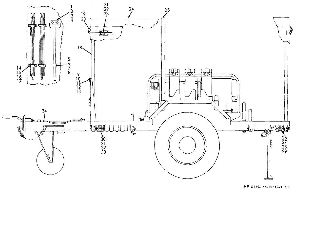
ME 6115-365-15/12-3 C3
TM 5-6115-365-15
C3
Figure 12-3. PU-564B/G.
12-17
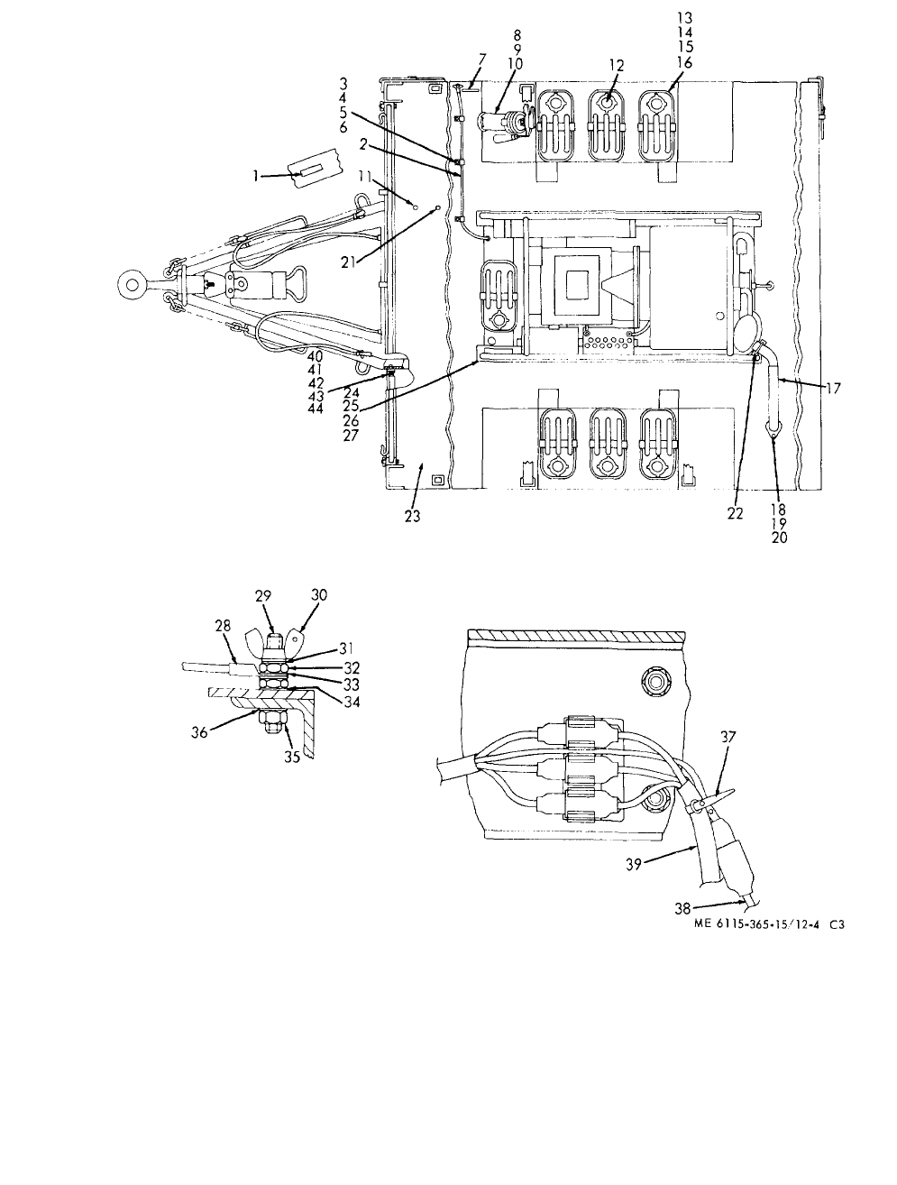
ME 6115-365-15/12-4 C3
TM 5-6115-365-15
C3
Figure 12-4. PU-564B/G accessories.
12-18

TM 5-6115-365-15
CHAPTER 13
GENERATOR SETS PU-253/U AND PU-253A/U
Section I. DESCRIPTION AND DATA
13-1. Description
a. General. The PU-253/U and PU-253A/U
Generator Sets consist of either two PU-107/U or PU-
107A/U gasoline Engine Generator sets (one in use, one
standby), mounted on a 2-wheeled, box type, steel body,
11/2-ton capacity, model M-105A1 or M-105E3 trailer.
Note
There is no switch gear assembly to
transfer the load from the operating
generator set to the standby
generator set. The load is connected
directly to the generator output
terminals For location of output
terminals refer to applicable technical
manuals (PU-107A/U generators) and
(PU-107/U generators).
b. Interchangeability. The gasoline engine
Generator Sets PU-107/U and PU-107A/U are
interchangeable, and can be mounted as a mixed pair.
c. Function. The PU-253/U and PU-253A/U
Generator Sets are a source of power for the Electronic
Search Control AN/GS]S-1 and for various types of
electronic and communication equipment.
d. PU-107/U. For description and further
information about PU-107/U, Generator Sets, refer to
applicable technical manual, as shown on generator set
nameplates or in DA Pam 310-4.
e. PU-107A/U. For description and further
information about units equipped with PU-107A/U
Generator Sets, refer to applicable technical manual, as
shown on generator set nameplates or in DA Pam 310-
4.
f. Generator. For description and further
information about the O'Keefe and Merritt, permanent
magnet type, 28 pole, 120/208-volt, one-or three-phase,
400-cycle generator, Signal Corp stock number 3H2441-
4, refer to applicable technical manual, as shown on
nameplates or in DA Pam 310-4. Applicable technical
manuals, as shown on nameplates or in DA Pam 310-4,
will provide description and additional information on the
John R. Hollingsworth Corporation model APG-H-11636
Generator.
g. Engine. Applicable technical manuals will
provide description and maintenance instructions for
Continental Motors Corporation model FS-162 gasoline
engine. Applicable technical manuals, as shown on
nameplate or in DA Pam 310-4, will contain description
and maintenance instructions for Willys-Overland model
807532 gasoline engine.
h. Trailer. For further trailer information, refer to
applicable technical manuals, as shown on trailer
nameplate or in DA Pam 310-4.
i. Lubrication. Lubricate the trailer in accordance
with instructions given in applicable lubrication order, as
shown in DA Pam 310-4. Applicable lubrication order,
as shown in DA Pam 310-4, contains instructions for
lubricating the PU-107A/U Generator Set. Lubricate
Willys-Overland gasoline engine model 807532 per
applicable lubrication order, as shown in DA Pam 310-4.
Lubricate Continental model FS-162 gasoline engine as
instructed by applicable lubrication order, as shown in
DA Pam 310-4. Applicable technical manual, as shown
in DA Pam 3104, contains instructions for lubricating the
PU-107/U Generator Set.
13-1
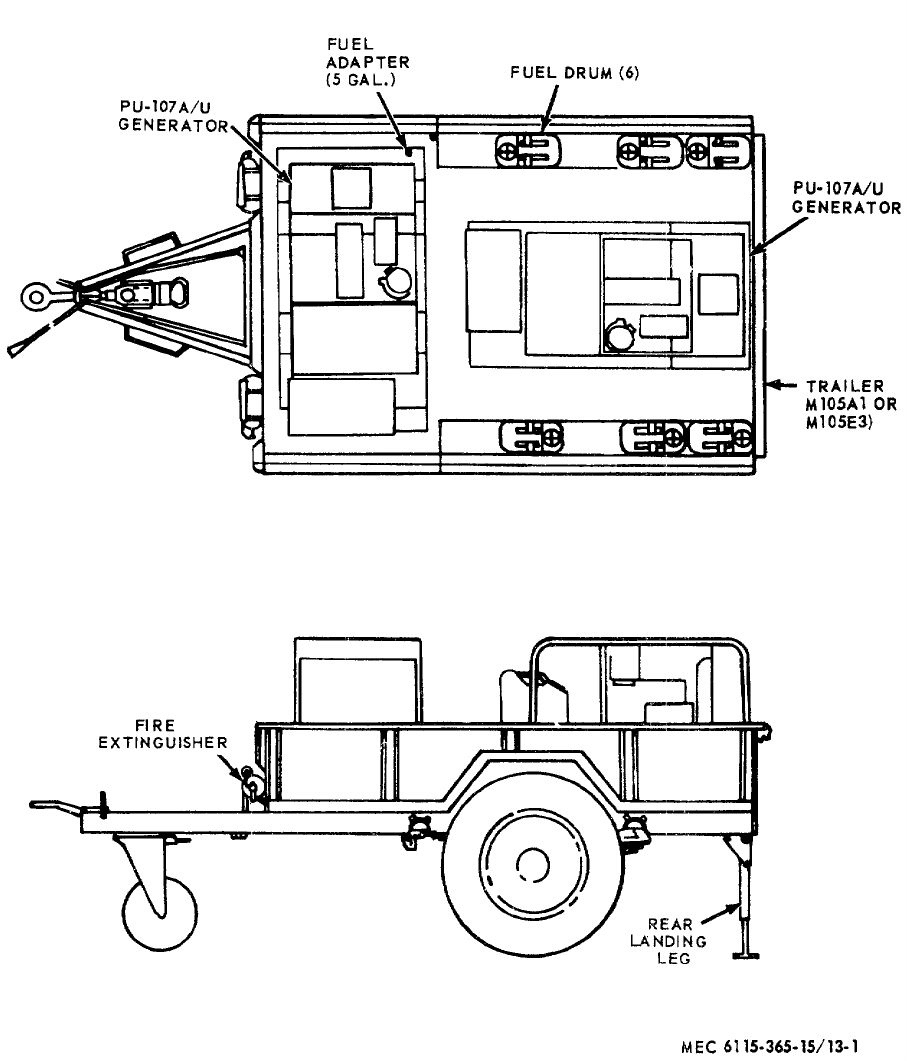
TM 5-6115-365-15
Figure 13-1. Generator Set PU-253A/U.
13-2
ILLUSTSOURCE
CODES
LINE
NO.
GUIDE QTY(S) PER MAJ EQUIPS
DESCRIPTION
15 DAYS MAINTENANCE
MANUFACTURER’S ORGANIZATION DS GS
MAINT
DEPOT
MATERIAL
SOURCE
MAINT
RECOVERABILITY
FEDERAL
STOCK
NUMBER
CODE PART NO.
UNIT OF ISSUE
QTY INCORPORATED
IN UIT
1-5 6-10 100 EQUIPMENTS
FIGURE NO.
ITEM NO.
TM 5 6115-365-15
Section II. REPAIR PARTS LIST
0002 GROUP 01 - ENGINE
0003 0106 - ENGINE LUBRICATION SYSTEM
0004 O4730-277-6440 NIPPLE, TUBE, BULKHEAD 88044 AN832-10 2* * * * *
0005 X2O 4720-913-6422 HOSE ASSEMBLY, RUBBER: OIL DRAIN 97403 13211E4918 2* * * * *
0006 O5310-282-7822 NUT, UNION: OIL DRAIN ROSE 88044 AN924-10 2* * * * *
0007 O5310-059-6372 WASHER, LOCK: OIL DRAIN NOSE 96906 MS35337-52 2* * * * *
0008 GROUP 04 - EXHAUST SYSTEM
0009 0401- MUFFLER AND PIPES
0010 X2O 6115-914-0256 HOSE ASSEMBLY, METAL: EXHAUST PIPE 97403 13214E1233-2 2* * * * *
0011 X2O 4730-914-4678 ADAPTER, STRAIGHT, PIPE TO LUBE: EXHAUST
PIPE 97403 13214E1234 2* * * * *
0012 X2O ELBOW, PIPE, STREET: EXHAUST PIPE, 90 DEC.
1 1/4 PIPE SIZE 96906 MS39230-7 2* * * * *
0013 GROUP 06 - ELECTRICAL SYSTEM ENGINE AND VEHICULAR, ETC.)
0014 0612 - BATTERIES, STORAGE (WET OR DRY)
0015 X2O 6140-914-5677 BOX, BATTERY 97403 13214E1242 2* * * * *
0016 X2O BASE, BATTERY BOX 97403 13214E1241 1* * * * *
0017 X2O TRAY, BATTERY 97403 13214E1244 1* * * * *
0018 X2O RETAINER, BATTERY BOX 97403 13214E1245 2* * * * *
0019 X2O RETAINER, BATTERY BOX 97403 13214E1246 1* * * * *
0020 X2O RETAINER, BATTERY 97403 13214E1247 1* * * * *
0021 X2O COVER, BATTERY BOX 97403 13214E1248 1* * * * *
0022 X2O THUMBSCREW: BATTERY BOX HOLDOWN 97403 13214E1249 4* * * * *
0023 X2O LATCH SET: BATTERY BOX 97403 13214E1251-12SS 2* * * * *
0024 X2O 5305-071-2235 SCREW, CA,HEXAGON HEAD: BATTERY BOX
MTG, 1/4-20 x 2-1/2 IN. LG 96906 MS90725-16 8* * * * *
0025 O5310-809-4058 WASHER, FLAT: BATTERY BOX MTG 96906 MS27183-10 16 * * * * *
0026 O5310-088-1251 NUT, SELF-LOCKING, HEXAGON: BATTERY BOX
MOUNTING 96906 MS51922-1 8* * * * *
0027 GROUP 15 - FRAME, TOWING ATTACHMENTS, AND DRAWBARS
0028 1501 - FRAME ASSEMBLY
0029 X2O 2510-706-4504 BRACKET, LIQUID CONTAINER, FUEL CAN 97403 13214E1203 6* * * * *
0030 X2O HOOK, DRIP RAIL: STRAP 97403 13212E3616 6* * * * *
0031 X2O FASTENER 97403 13214E1205 6* * * * *
0032 X2O BUCKLE 96906 MS51940-7 12 * * * * *
0033 MOSTRAP, TOP 97403 13214E1203-2 6* * * * *
MANUFACTURE FROM:
0034 PO8305-267-3009 WEBBING, NYLON 06716 1403 FT SEE GRP 9501
(30 IN. REQUIRED FOR EACH STRAP)
0035 MOSTRAP, BOTTOM 97403 13214E1203-3 6* * * * *
MANUFACTURE FROM:
0036 PO8305-267-3009 WEBBING, NYLON 06716 1403 FT SEE GRP 9501
0037 X2O (18 IN. REQUIRED FOR EACH STRAP)
0038 X2O BRACKET 97403 13214E1204 6* * * * *
0039 X2O 5305-269-3210 SCREW, CAP, HEXAGON HEAD: FUEL CAN
BRACKET MTG 96906 MS90725-59 24 * * * * *
0039 O5310-809-4061 WASHER, FLAT: FUEL CAN BRACKET MTG 96906 MS27183-15 24 * * * * *
0040 O5310-087-4652 NUT, SELF-LOCKING, HEXAGON: FUEL CAN
BRACKET MTG 96906 MS51922-17 24 * * * * *
0011 X2O LOOP, STRAP FASTENER: FUEL C 96906 MS51939-2 2* * * * *
0042 O5305-984-6211 SCREW, MACHINE: LOOP 96906 MS35206-264 4* * * * *
0043 O5310-809-8546 WASHER, FLAT: LOOP NT 96906 MS27183-8 4* * * * *
O044 O5310-167-0662 WASHER, LOCK: LOOP 96906 MS35337-43 4* * * * *
0045 O5310-102-0361 NUT, PLAIN, HEXAGON: LOOP MTG 96906 MS35649-102 4* * * * *
0046 X2O 6115-016-2362 HOLDER COMPONENT: FUEL DRUM ADAPTER
EXTENSION 97403 13211E4889-1 4* * * * *
0047 O5305-889-3000 SCREW, MACHINE: EXTENSION HOLDER MTG 96906 MS35206-230 8 * * * * *
0048 O5310-082-1404 WASHER FLAT: EXTENSION HOLDER MTG 96906 MS27183-6 8* * * * *
0049 O5310-596-7674 WASHER, LOCK: EXTENSION HOLDER MTG 96906 MS35337-22 8* * * * *
0050 O5310-062-0912 NUT, PLAIN, HEXAGON: EXTENSION HOLDER
MOUNTING 96906 M35649-64 8* * * * *
0051 X2O 7240-920-5327 HOLDER, SPOUT: FUEL DRUM ADAPTER 974903 13212E3553-1 2* * * * *
13-3

ILLUSTSOURCE
CODES
LINE
NO.
GUIDE QTY(S) PER MAJ EQUIPS
DESCRIPTION
15 DAYS MAINTENANCE
MANUFACTURER’S ORGANIZATION DS GS
MAINT
DEPOT
MATERIAL
SOURCE
MAINT
RECOVERABILITY
FEDERAL
STOCK
NUMBER
CODE PART NO.
UNIT OF ISSUE
QTY INCORPORATED
IN UIT
1-5 6-10 100 EQUIPMENTS
FIGURE NO.
ITEM NO.
TM 5 6115-365-15
Section II. REPAIR PARTS LIST
0052 X2O 5306-225-8497 BOLT, MACHINE: ADAPTER HOLDER MTG
5/16-18 x 3/4 IN. LG 96906 MS90725-32 4* * * * *
0053 O5310-081-4219 WASHER, FLAT: ADAPTER HOLDER MTG 96906 MS27183-12 8* * * * *
0054 O5310-984-3806 NUT, SELF-LOCKING, HEXAGON: ADAPTER
HOLDER HTG 96906 MS51922-9 4* * * * *
0055 X2O BRACKET ASSEMBLY, SLEDGE HAMMER 97403 13214E1214 1* * * * *
0056 X2O BRACKET 97403 13214 E1215 1* * * * *
0057 O531-080-8495 NUT, PLAIN, WING 96906 MS35425-39 2* * * * *
0058 X2O PLATE, HOLDOWN 97403 13214E1216 1* * * * *
0059 O5310-809-4058 WASHER, FLAT 96906 M27183-10 2* * * * *
0060 O5310-043-5862 WASHER, LOCK 96906 MS35337-82 2* * * * *
0061 X2O 5340-914-2578 CLIP, SPRING TENSION: SLEDGE HAMMER
HANDLE 97403 13214E1213-1 1* * * * *
0062 X2O 5305-068-0502 SCREW, CAP, HEXAGON HEAD: SLEDGE HAMMER
AND CLIP MTG 96906 MS90725-6 3* * * * *
0063 O5310-809-4058 WASHER, FLAT: SLEDGE HAMMER AND CLIP MTG 96906 MS27183-10 10 * * * * *
0064 O5310-088-1251 NUT, SELF-LOCKING, HEXAGON: SLEDGE HAMMER
CLIP MTG, AND GROUND ROD CLAMP BRACKET 96906 MS51922-1 7* * * * *
0065 X2O 5975-878-3791 ROD, GROUND TYPE II STYLE 2 1* * * * *
0066 X2O CLAMP, GROUND ROD 97403 13212E3617 2* * * * *
0067 O5305-958-5246 SCREW, MACHINE: GROUND ROD CLAMP MTG 96906 MS3519-289 4* * * * *
0068 X2O 5314-526-2559 CLAMP, LOOP: GROUND WIRE 96906 MS21919F2 2* * * * *
0069 O5305-984-6211 SCREW, MACHINE: GROUND WIRE CLAMP MTG 96906 MS35206-264 2* * * * *
0070 O5310-809-8546 WASHER, FLAT: GROUND WIRE CLAMP MTG 96906 MS27183-8 4* * * * *
0071 O5310-167-0662 WASHER, LOCK: GROUND WIRE CLAMP MTG 96906 MS35337-43 4* * * * *
0072 O5310-012-0361 NUT, PLAIN, .HEXAGON: GROUND WIRE CLAMP
MOUNTING 96906 MS35649-102 2* * * * *
0073 X2O 5307-722-9437 STUD, CONTINUOUS THREAD: GROUND 97403 13214E1223 1* * * * *
0074 X2O WASHER, LOCK: BRONZE, EXTERNAL TOOTH,
3/8 IN. GROUND STUD 96906 MS35335-91 2* * * * *
0075 O5310-835-7478 NUT, PLAIN, HEXAGON: BRASS, GROUND STUD
TO TRAILER 96906 MS35691-611 2* * * * *
0076 X2O 5310-900-6323 WASHER, FLAT: BRASS, GROUND STUD 96906 MS45901-7 2* * * * *
0077 O5310-720-8528 NUT, PLAIN, HEXAGON: BRASS, GROUND STUD 96906 MS35690-611 1* * * * *
0078 O5310-543-4717 NUT, PLAIN, WING: BRASS, GROUND STUD 96906 MS35425-8 1* * * * *
0079 1507 - LANDING GEAR, LEVELING JACKS (MECHANICAL OR HYDRAULIC)
0080 X2O 2590-318-6691 LEG TRAILER PROP 97403 13214E1026 1* * * * *
0081 X2O BRACKET 97403 13214E1207 1* * * * *
0082 X2O LEG ASSEMBLY, UPPER 97403 13214E1208 1* * * * *
0083 X2O CHAIN: PIN RETAINING 97403 13214E1208-6 1* * * * *
0084 X2O PIN 97403 13214E1208-5 1* * * * *
0085 X2O LEG, BASE 97403 13214E1212 1* * * * *
0086 X2O SHAFT 97403 13214E1209 1* * * * *
0087 O4730-172-0049 FITTING, LUBRICATION 96906 MS15006-1 * * * * *
0088 X2O SCREW 97403 13214E1210 1* * * * *
0089 X2O NUT 97403 13214E1211 1* * * * *
0090 X2O RIVET, SOLID, UNIVERSAL HEAD:
1/4 IN. DIA 96906 MS20613-8P32 1* * * * *
0091 X2O PIN, COTTER: 1/8 IN. DIA, 3/4 IN. LG 96906 MS24665-351 1* * * * *
0092 X2O 5305-269-3213 SCREW, CAP, HEXAGON HEAD: LEG ASSEMBLY
TO TRAILER, 3/8-16 x 1 1/4 IN. LG 96906 MS90725-62 3* * * * *
0093 O5310-809-4061 WASHER, FLAT: LEG ASSEMBLY TO TRAILER 96906 MS27183-15 6* * * * *
0094 O5311-087-4652 NUT, SELF-LOCKING, HEXAGON: LEO ASSEMBLY
TO TRAILER 96906 MS51922-17 3* * * * *
0095 GROUP 18 - BODY, CAB, HOOD AND HULL
0096 1810 - CARGO BODY (DUMP, STAKE, AND PLATFORM)
0097 X2F 2330-141-8050 TRAILER: (M105) 97403 13214E241 1* * *
0098 GROUP 22 - BODY CHASSIS OR HULL, AND ACCESSORY ITEMS
0099 2202 - ACCESSORY ITEMS
0100 X2O 7240-222-3088 CAN, GASOLINE: MILITARY, 5 GAL MILC1283 2* * * * *
0101 X2O 7240-177-6154 SPOUT, CAN, FLEXIBLE: FUEL CAN 2* * * * *
0102 X2O 2910-066-1235 ADAPTER, ASSEMBLY FUEL TANK 13211E7541 2* * * * *
0103 X2O PIPE 97403 13211E7542 2* * * * *
0104 X2O WASHER, BRASS 97403 13211E7544 2* * * * *
0105 X2O SCREW, SHOULDER 97403 13211E17545 4* * * * *
0106 X2O RING, SEALING 97403 13211E7546 2* * * * *
0107 X2O WASHER, RUBBER 97403 13211E754 2* * * * *
0108 X2O HEAD 97403 13211E7548 2* * * * *
13-4

ILLUSTSOURCE
CODES
LINE
NO.
GUIDE QTY(S) PER MAJ EQUIPS
DESCRIPTION
15 DAYS MAINTENANCE
MANUFACTURER’S ORGANIZATION DS GS
MAINT
DEPOT
MATERIAL
SOURCE
MAINT
RECOVERABILITY
FEDERAL
STOCK
NUMBER
CODE PART NO.
UNIT OF ISSUE
QTY INCORPORATED
IN UIT
1-5 6-10 100 EQUIPMENTS
FIGURE NO.
ITEM NO.
TM 5 6115-365-15
Section II. REPAIR PARTS LIST
0109 X2O WASHER, STEEL 97403 13200E6361 2* * * * *
0110 X2O CLAMP 97403 13200E6363 2* * * * *
0111 O5310-209-1239 WASHER, LOCK: SHOULDER SCREW 96906 MS35335-60 4* * * * *
0112 X2O PIPE, EXTENSION 97403 13211E7542 2* * * * *
0113 X2O 4730-914-4678 ADAPTER, STRAIGHT, PIPE TO HOSE 13214E1234 2* * * * *
0114 2210 - ATA PLATES AND INSTRUCTION HOLDERS
0115 X2O NAMEPLATE: ACCESSORY BOX 14850 D900-468X 1* * * * *
0116 X2O NAMEPLATES FIRE EXTINGUISHER 14850 D9-284-3 1* * * * *
0117 X2O NAMEPLATE: GENERATOR SET 97403 13212E3599 1* * * * *
0118 X2O WASHER, LOCK 96906 MS35337-77 4* * * * *
0119 X2O 530-548-2088 SCREW, TAPPING, THREAD FORMING 96206 MS24622-3 4* * * * *
0120 X2O NAMEPLATE: GROUND ROD 14850 D9-28&2 1* * * * *
0121 X2O NAMEPLATE: GROUND TERMINAL 14850 D9-11A 1* * * * *
0122 X2O NAMEPLATE: SLEDGE HAMMER 14850 D9-28A1 1* * * * *
0123 X2O SCREW, DRIVE: No. 2 NAMEPLATE MTG 14850 A1-1613F46 14 * * * * *
0124 X2O PLATE, IDENTIFICATION 97403 13212E3599 1* * * * *
0125 GROUP 40 - ELECTRIC MOTORS AND GENERATORS
0126 4000 - MAJOR ASSEMBLAGE
0127 X2FR 6115-548-1377 GENERATOR SET, GASOLINE ENGINE 02032 APGH11636 2* * *
0126 X2F 5305-724-5910 SCREW, CAP, HEXAGON HEAD: GENERATOR MTG 96906 MS90725-162 8* * *
0129 XF5310-823-8803 WASHER, FLAT: GENERATOR MTG 96906 M27183-21 16 * * *
0130 X2F SHIM: GENERATOR MTG 97403 13214E1222-3 8* * *
0131 X2F 5310-269-4040 NUT, SELF-LOCKING, HEXAGON: GENERATOR
MOUNTING 96906 MS51922-49 8* * *
0132 4019 - RADIO INTERFERENCE SUPPRESSION
0133 MOWIRE, ELECTRICAL (UNINSULATED): GENERATOR 1
TO GROUND STUD
MANUFACTURE FROM:
0134 PO6145-299-4456 WIRE, ELECTRICAL (LENGTH AS REQUIRED) 96906 QQW343 FT SEE GRP 9501
0135 GROUP 76 - FIRE FIGHTING EQUIPMENT COMPONENTS
0136 7603 - FIRE EXTINGUISHERS
0137 P1O 4210-555-8837 EXTINGUISHER, FIRE:
MONOBROMOTRIFLOUROMETHANE 1* * * * *
0138 X2O BRACKET, FIRE EXTINGUISHER 14850 D443C 1* * * * *
0139 X2O 5305-068-0502 SCREW, CAP, HEXAGON HEAD: EXTINGUISHER T
MTG, 1/4-20 x 3/4 IN. LG 96906 MS90725-6 4* * * * *
0140 O5310-809-4058 WASHER, FLAT: EXTINGUISHER T96906 MS27183-10 8* * * * *
0141 O5310-088-1251 NUT, SELF-LOCKING, HEXAGON: EXTINGUISHER
MOUNTING 96906 MS51922-1 4* * * * *
0142 P1O 4210-270-4512 EXTINGUISHER, FIRE 1* * * * *
0143 X2O 6115-606-9338 BRACKET, FIRE EXTINGUISHER 1* * * * *
0144 GROUP 95 - GENERAL USE STANDARDIZED PARTS
0145 9501 - BULK MATERIAL
o146 PO8305-267-3009 WEBBING, NYLON 06716 1403 FT * * * * *
0147 PO6145-857-6903 WIRE, ELECTRICAL FT * * * * *
13-5

TM 5-6115-365-15
CHAPTER 14
GENERATOR SETS PU-375/G AND PU-375A/G
Section I. DESCRIPTION AND DATA
14-1. Description
a. General. The PU-375/G and PU-375A/G
Generator Sets consist of either a PU-107/U or PU-
107A/U gasoline engine generator set, mounted on a
two-wheel, box type steel body, 3/4-ton capacity, cargo
trailer, type M101.
b. Function. The PU-375/G and PU-375A/G
Generator Sets provide mobile facilities for AC and DC
power for Radio Set AN/TPS-1D.
c. PU-107/U. For description and further
information on PU-107/U Generator Sets, refer to
applicable technical manual, as shown on generator set
nameplate or in DA Pam 310-4.
d. PU-107A/U. For description and further
information about units equipped with PU-107A/U
Generator Sets, refer to applicable technical manual, as
shown on generator set nameplate or in DA Pam 310-4,
and DA supply manual ENG 7, 8 and 9.
e. Generator. For description and further
information about the O'Keefe and Merritt, permanent
magnet type, 28-pole, 120/208-volt, one or three phase,
400-cycle generator, Signal Corp, stock number
3H2441-4, refer to TM 11-919. Applicable technical
manuals, as shown on nameplate or in DA Pam 310-4,
will provide description and additional information on the
John R. Hollingsworth Corporation model APG-H-11636
Generator.
f. Engine. Applicable technical manuals, as
shown on nameplates or in DA Pam 310-4, provide
description and maintenance instructions for Continental
Motors Corporation model FS-162 gasoline engine.
Applicable technical manuals, as shown on nameplate or
in DA Pam 310-4, contain description and maintenance
instructions for Willys-Overland model 807532 gasoline
engine.
g. Trailer. For further trailer information, refer to
applicable technical manual, as shown on trailer
nameplate or in DA Pam 310-4.
h. Lubrication. Lubricate the trailer in accordance
with instructions given in applicable technical manual, as
shown in DA Pam 310-4. Applicable lubrication orders,
as shown in DA Pam 310-4, contains instructions for
lubricating the PU-107A/U Generator Set. Lubricate
Willys-Overland gasoline model 807532 per LO 5-5235.
Lubricate Continental model FS-162 gasoline engine as
instructed by applicable lubrication order, as shown in
DA Pam 310-4. Applicable technical manual, as shown
in DA Pam 310-4, contains instructions for lubricating the
PU-107/U Generator Set.
14-1
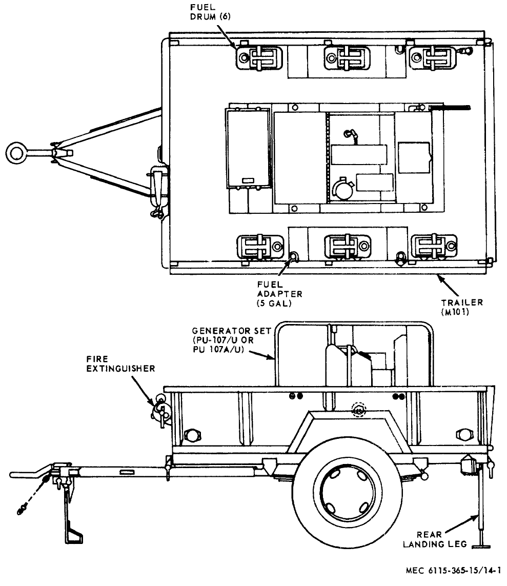
TM 5-6115-365-15
Figure 14-1. Generator Set PU-756A/G.
14-2
TM 5-6115-365-15
Section II. REPAIR PARTS LIST
(Parts data will be developed at a later date)
14-3

TM 5-6115-365-15
CHAPTER 15
GENERATOR SET PU-551/G
Section I. DESCRIPTION AND DATA
15-1. Description
a. General. A diesel engine-driven, 45-kw, 60-
cycle, ac generator, mounted on a 2 (dual) wheeled,
flatbed steel body, 21/2-ton capacity, model M200A1
trailer, comprise the Generator Set PU-551/G.
b. Function. The PU-551/G Generator Set is a
general purpose generator set and has multiple
applications.
c. Generator Sets. For description and further
information on Consolidated Diesel Electric model 4070
sets, refer to applicable technical manuals, as shown on
generator set nameplate or in DA Pam 310-4.
d. Engine. For description and further information
on the Continental Motors Corporation model TD 427-
2281 diesel engine, refer to applicable technical
manuals, as shown on nameplate or in DA Pam 310-4.
e. Trailer. For description and further trailer
information, refer to applicable technical manuals, as
shown on trailer nameplate or in DA Pam 310-4.
f. Lubrication. Refer to applicable technical
manual, as shown in DA Pam 310-4, for trailer
lubrication information.
15-1
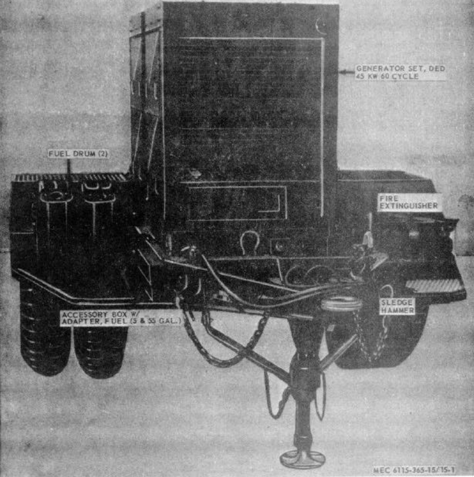
TM 5-6115-365-15
Figure 15-1. Generator Set PU-551/G.
15-2

ILLUSTSOURCE
CODES
LINE
NO.
GUIDE QTY(S) PER MAJ EQUIPS
DESCRIPTION
15 DAYS MAINTENANCE
MANUFACTURER’S ORGANIZATION DS GS
MAINT
DEPOT
MATERIAL
SOURCE
MAINT
RECOVERABILITY
FEDERAL
STOCK
NUMBER
CODE PART NO.
UNIT OF ISSUE
QTY INCORPORATED
IN UIT
1-5 6-10 100 EQUIPMENTS
FIGURE NO.
ITEM NO.
TM 5 6115-365-15
Section II. REPAIR PARTS LIST
0002 GROUP 15 - FRAME, TOWING ATTACHMENTS, AND DRAWBARS
0003 1501 - FRAME ASSEMBLY
0004 X2O 2510-706-4504 BRACKET ASSEMBLY, FUEL CAN 97403 13214E1203 2* * * * * 15-2 1
0005 X2O BRACKET 97403 13214E1204 2* * * * *
0006 X2O BUCKLE 96906 MS51940-7 2* * * * *
0007 X2O FASTENER 97403 13214E1205 2* * * * *
0008 X2O HOOK, DRIP RAIL 97403 13212E3616 2* * * * *
0009 MOSTRAP, BOTTOM 97403 13214E1203-3 2
MANUFACTURE FROM:
0010 PO8305-267-3009 WEBBING, NYLON 06716 1403 FT SEE GRP 9501
(18 IN. REQUIRED FOR EACH STRAP)
0011 MOSTRAP, TOP 97403 13214E1203-2 2
MANUFACTURE FROM:
0012 PO8305-267-3009 WEBBING, NYLON 06716 1403 FT SEE GRP 9501
(30 IN. REQUIRED FOR EACH STRAP)
0013 O5310-984-3806 NUT, SELF-LOCKING, HEXAGON: FUEL CAN
BRACKET MTG 96906 MS51922-9 8* * * * *
0014 O5306-225-8497 SCREW, CAP, HEXAGON: FUEL CAN BRACKET
MOUNTING 96906 MS90725-32 8* * * * *
0015 O5310-081-4219 WASHER, FLAT: FUEL CAN BRACKET MTG 96906 MS27183-12 8* * * * *
0016 X2O BRACKET ASSEMBLY, GROUND ROD 97403 13214E1288 1* * * * *
0017 X2O BRACKET, GROUND ROD 14850 A116-726 1* * * * *
0011 X2O HOLDER, GROUND ROD 14850 D116-725Y 1* * * * *
0019 X2O 5306-225-8498 SCREW, CAP, HEXAGON HEAD: GROUND ROD MTG 96906 MS90725-33 2* * * * *
0020 O5310-081-41219 WASHER, FLAT: GROUND ROD MTG 96906 MS27183-12 2* * * * *
0021 X2O 5310-984-3806 NUT, SELF-LOCKING: GROUND ROD MTG 96906 MS51922-9 2* * * * *
0022 X2O BRACKET ASSEMBLY, SLEDGE HAMMER 97403 13214E1214 1* * * * * 15-24
0023 X2O BRACKET, SLEDGE HAMMER 14850 A116-740Y 1* * * * *
0024 X2O HOLDER, SLEDGE HAMMER 14850 D116-741X 1* * * * *
0025 X2O 5340-914-2578 CLIP, SPRING: SLEDGE HAMMER BRACKET 97403 13214E1213-1 1* * * * *
0026 X2O 5310-088-1251 NUT, SELF-LOCKING, HEXAGON: SLEDGE HAMMER
BRACKET MTG 96906 MS51922-1 3* * * * *
0027 O5305-068-0502 SCREW, CAP, HEXAGON HEAD: SLEDGE HAMMER
BRACKET MTG 96906 MS90725-6 3* * * * *
0028 O5310-809-4058 WASHER, FLAT: SLEDGE HAMMER BRACKET MTG 96906 MS27183-10 3* * * * *
0029 X2O ANCHOR, PLATFORM 97403 13214E1303 2* * * * *
0030 X2O BRACKET, PLATFORM: LEFT HAND 97403 13214E1299 1* * * * *
0031 X2O BRACKET, PLATFORM.: RIGHT HAND 97403 13214E1300 1* * * * *
0032 X2O NUT, SELF-LOCKING, HEXAGON: PLATFORM
BRACKET MTG 96906 MS51922-33 6* * * * *
0033 O5305-053-8993 SCREW, CAP, HEXAGON HEAD: PLATFORM MTG
BRACKET 96906 MS90725-112 6* * * * *
0034 O5310-809-3079 WASHER, FLAT: PLATFORM BRACKET MTG 96906 MS27183-19 6* * * * *
0035 X2O CLAMP, PLATFORM 97403 13214E1302 1* * * * *
0036 X2O ROD, CLAMP 97403 13214E1301 1* * * * *
0037 O5310-889-2606 NUT, PLAIN, WING: CLAMP MTG 96906 MS535425-41 1* * * * *
0038 O5315-013-7946 PIN, COTTER: CLAMP MTG 96906 MS24665-349 1* * * * *
0039 X2O PLATFORM, PERSONNEL 97403 13214E1298 1* * * * *
0040 O5310-067-6356 NUT, SELF-LOCKING, HEXAGON: PLATFORM MTG 96906 MS51922-57 2* * * * *
0041 X2O SCREW, CAP, HEXAGON HEAD: PLATFORM MTG 96906 MS90725-187 2* * * * *
0042 O5310-809-8533 WASHER, FLAT: PLATFORM MTG 96906 M527183-23 2* * * * *
0043 X2O STUD, GROUND WIRE 97403 13214E1223 1* * * * *
0044 5310-720-8531 NUT, PLAIN, HEXAGON: GROUND STUD 96906 MS35691-611 2* * * * *
0045 5310-720-8528 NUT, PLAIN, HEXAGON: GROUND STUD 96906 MS35690-611 1* * * * *
0046 O5310-543-4717 NUT, PLAIN, WING: GROUND STUD 96906 MS35425-28 1* * * * *
0047 X2O WASHER, FLAT: GROUND STUD 96906 MS45901-7 4* * * * *
0048 X2O WASHER, LOCK: GROUND STUD 96906 MS35335-91 1* * * * *
0049 GROUP 18 - BODY, CAB, HOOD AND HULL
0050 1808 - STOWAGE RACKS, BOXES, STRAPS, CARRYING CASES,
CABLE REELS, HOSE REELS, ETC.
0051 X2O 6115-705-4604 CHEST, ACCESSORY STOWAGE 97403 13214E1273 1* * * * * * 15-2 3
0052 O5310-984-3806 NUT, SELF-LOCKING, HEXAGON: ACCESSORY
CHEST MTG 96906 MS51922-9 2* * * * * *
0053 X2O 5306-225-8497 SCREW, CAP, HEXAGON: ACCESSORY CHEST MTG 96906 MS90725-32 2* * * * * *
0054 O5310-081-4219 WASHER, FLAT: ACCESSORY CHEST MTG 96906 MS27183-12 2* * * * * *
15-3

ILLUSTSOURCE
CODES
LINE
NO.
GUIDE QTY(S) PER MAJ EQUIPS
DESCRIPTION
15 DAYS MAINTENANCE
MANUFACTURER’S ORGANIZATION DS GS
MAINT
DEPOT
MATERIAL
SOURCE
MAINT
RECOVERABILITY
FEDERAL
STOCK
NUMBER
CODE PART NO.
UNIT OF ISSUE
QTY INCORPORATED
IN UIT
1-5 6-10 100 EQUIPMENTS
FIGURE NO.
ITEM NO.
TM 5 6115-365-15
Section II. REPAIR PARTS LIST
0055 1810 - CARGO BODY
(DUMP, STAKE, AND PLATFORM)
0056 X2FR 2330-331-2307 TRAILER: 2 1/2 TON M200A1 1* * *
0057 GROUP 22 - BODY CHASSIS OR HULL, AND ACCESSORY ITEMS
0058 2202 - ACCESSORY ITEMS
0059 X2O 6145-189-6695 LEAD, GROUND 1* * * * *
0060 X2O 7240-222-3088 CAN, FUEL: 5 GAL 2* * * * * 15-2 2
0061 X2O 7240-177-6154 NOZZLE, FLEXIBLE: FUEL CAN 1* * * * *
0062 X2O 6115-319-3991 ADAPTER, FUEL CAN 1* * * * *
0063 X2O PIPE 97403 13211E7543 1* * * * *
0064 X2O WASHER, BRASS 97403 13211E7544 2* * * * *
0065 X2O SCREW, SHOULDER 97403 13211E7545 2* * * * *
0066 X2O RING, SEALING 97403 13211E7546 1* * * * *
0067 X2O WASHER, RUBBER 97403 13211E7547 1* * * * *
0068 X2O HEAD 97403 13211E7548 1* * * * *
0069 X2O WASHER, STEEL 97403 13200E6361 1* * * * *
0070 X2O CLAMP 97403 13200E6363 1* * * * *
0071 O5310-209-1239 WASHER, LOCK 96906 MS35335-6 1* * * * *
0072 X2O PIPE, EXTENSION 97403 13211E7542 1* * * * *
0073 O4730-278-3357 ADAPTER, STRAIGHT: HOSE 1* * * * *
0074 2210 - DATA PLATES AND INSTRUCTION HOLDERS
0075 X2O NAMEPLATE: ACCESSORY BOX 14350 D900-468X 1* * * * *
0076 X2O NAMEPLATE: FIRE EXTINGUISHER 14830 D9-284-3 2* * * * *
0077 X2O NAMEPLATE: GROUND ROD 14850 D9-28A2 1* * * * *
0078 X2O NAMEPLATE: GROUND ROD 14850 D9-11A 1* * * * *
0079 X2O NAMEPLATE: IDENTIFICATION: POWER UNIT 97403 13212E3599 1* * * * *
0080 X2O NAMEPLATE: SLEDGE HAMMER 14850 D9-28A1 1* * * * *
0081 X2O NAMEPLATE, IDENTIFICATION: DISTRIBUTION
BOX 97403 13214E1284 1* * * * *
0082 X2O NAMEPLATE: WIRING DIAGRAM 97403 13214E1283 1* * * * *
0083 X2O SCREW, TAPPING: PAN HEAD, NAMEPLATE MTG
No. 2-32 x 1/4 IN. LG 96906 MS24622-3 2* * * * *
0084 X2O SCREW, TAPPING: PAN HEAD, NAMEPLATE MTG
No. 4-24, 1/4 IN. LG 96906 MS24622-8 8* * * * *
0085 X2O SCREW, TAPPING: PAN HEAD, NAMEPLATE MTG
No. 4, 5/16 IN. LG 96906 MS24646-9 14 * * * * *
0086 GROUP 40 - ELECTRIC MOTORS AND GENERATORS
0087 4000- MAJOR ASSEMBLE
0088 X2FR 6115-970-0006 GENERATOR, DIESEL ENGINE: 45 KW 1* * * 15-2 4
0089 X2F 5306-180-0094 BOLT, MACHINE: AIRCRAFT, 5/-18, 41/64
IN. LG GENERATOR MTG 8044 AN10-14A 4* * *
0090 X2F NUT, SELF-LOCKING, HEXAGON: GENERATOR
MOUNTING 96906 MS511922-53 4* * *
0091 X2F WASHER, BEVELED: GENERATOR MTG 97403 13206E4482-3 4* * *
0092 F5310-951-7209 WASHER, FLAT: GENERATOR MTG 96906 MS27183-22 4* * *
0093 4019 - RADIO INTERFERENCE SUPPRESSION
0094 MOWIRE, ELECTRICAL: GENERATOR TO GROUND
STUD 81349 QQW343 1
MANUFACTURE FROM:
0095 PO6145-857-6903 WIRE, ELECTRICAL (LENGTH AS REQUIRED) FT SEE ;RP 9501
0096 GROUP 42 - ELECTRICAL EQUIPMENT
0097 4201 - TRANSFORMER, POWER LINE OR DISTRIBUTION
0098 X2O DISTRIBUTION BOX 97403 13214E1276 1* * * * *
0099 X2O BOX: DISTRIBUTION 97403 13214E1277 1* * * * *
0100 X2O TERMINAL BOARD: DISTRIBUTION BOX 97403 13214E1278 1* * * * *
0101 X2O SCREW, CAP, HEXAGON HEAD: TERMINAL
BOARD MTG 96906 MS90725-9 6* * * * *
0102 O5310-809-4058 WASHER, FLAT: TERMINAL BOARD MTG 96906 MS27183-10 4* * * * *
0103 O5310-088-1251 NUT, SELF-LOCKING, HEXAGON: TERMINAL
BOARD MTG 96906 MS51922-1 6* * * * *
0104 X2O STUD, SHOULDER: DISTRIBUTION BOX MTG 97403 13214E1279-3 4* * * * *
0105 X2O WASHER, FLAT: DISTRIBUTION BOX MTG 96906 M45901-7 20 * * * * *
15-4

ILLUSTSOURCE
CODES
LINE
NO.
GUIDE QTY(S) PER MAJ EQUIPS
DESCRIPTION
15 DAYS MAINTENANCE
MANUFACTURER’S ORGANIZATION DS GS
MAINT
DEPOT
MATERIAL
SOURCE
MAINT
RECOVERABILITY
FEDERAL
STOCK
NUMBER
CODE PART NO.
UNIT OF ISSUE
QTY INCORPORATED
IN UIT
1-5 6-10 100 EQUIPMENTS
FIGURE NO.
ITEM NO.
TM 5 6115-365-15
Section II. REPAIR PARTS LIST
0106 O5310-576-0548 WASHER, LOCK: DISTRIBUTION BOX MTG 96906 MS35337-103 12 * * * * *
0107 O5310-685-2632 NUT, PLAIN, HEXAGON DISTRIBUTION BOX
MOUNTING 96906 MS35691-612 16 * * * * *
0108 X2O PANEL 97403 13214E1280 1
0109 O5305-988-1722 SCREW, MACHINE: PAN HEAD PANEL MTG 96906 MS35206-278 8* * * * *
0110 X2O NAMEPLATE: DISTRIBUTION BOX 97403 13214E1284 1SEE GRP 2210
0111 X2O CABLE ASSEMBLY: DISTRIBUTION BOX 97403 13214E1282-2 1* * * * *
0112 X2O CABLE ASSEMBLY: DISTRIBUTION BOX 97403 13214E1282-1 1* * * * *
0113 X2O SCREW MACHINE: PAN HEAD, No. 10-32,
5/8 IN.LG 96906 MS35207-264 8* * * * *
0114 X2O 5310-809-8546 WASHER, FLAT 96906 MS27183-8 8* * * * *
0115 X2O 5310-167-0662 WASHER, LOCK 96906 MS35337-43 8* * * * *
0116 O5310-102-0614 NUT, PLAIN, HEXAGON 96906 MS3650-102 8* * * * *
0117 X2O NAMEPLATE: WIRING DIAGRAM 97403 13214E1283 1SEE RP 2210
0118 X2O CONNECTOR AND LOCKNUT 97403 13212E3582-3 1* * * * *
0119 X2O COVER, ELECTRICAL CONNECTOR 960 MS17349N36B 2* * * * *
0120 GROUP 76 - FIRE FIGHTING EQUIPMENT COMPONENTS
0121 7603 - FIRE EXTINGUISHERS
0122 P1O 4210-555-8837 EXTINGUISHER, FIRE 1* * * * * 15-2 6
0123 X2O 6115-606-9938 BRACKET, FIRE EXTINGUISHER 14850 D443C 1* * * * *
(USED WITH FIRE EXTINGUISHER STOCK No.
4210-555-8837)
0124 X2O 5305-068-0502 SCREW, CAP, HEXAGON HEAD: EXTINGUISHER
MTG. 1/4 - 20, 3/4, IN. LG 96906 MS90725-6 4* * * * *
0125 O5310-809-4058 WASHER, FLAT: EXTINGUISHER 96906 MS527183-10 8* * * * *
0126 O5310-088-1251 NUT, SELF-LOCKING, HEXAGON EXTINGUISHER
MOUNTING 96906 MS51922-1 8* * * * *
0127 P1O 4210-270-4512 EXTINGUISHER, FIRE 1* * * * *
0128 X2O 6115-606-9338 BRACKET, FIRE EXTINGUISHER 1* * * * *
(USED WITH FIRE EXTINGUISHER STOCK No.
4210-270 512)
0129 GROUP 95 - GENERAL USE STANDARDIZED PARTS
0130 9501 - BULK MATERIAL
0131 PO8305-267-3009 WEBBING, NYLON 06716 1403 FT * * * * *
0132 PO6145-857-6903 WIRE, ELECTRICAL FT * * * * *
15-5
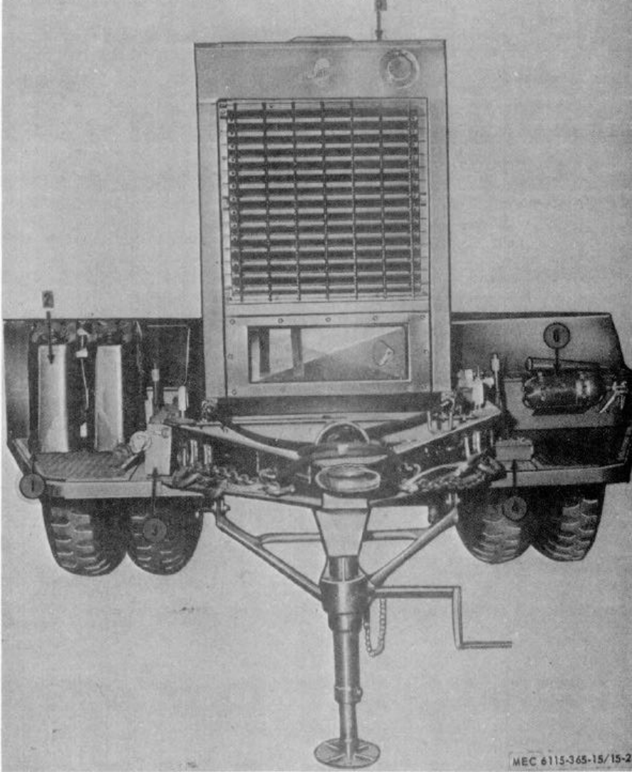
TM 5-6115-365-15
1Bracket 4Bracket
2Can 5Generator
3Box 6Extinguisher
Figure 15-2. Accessories.
15-6
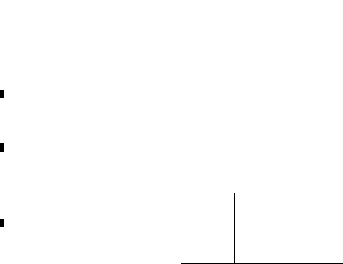
TM 5-6115-365-15
CHAPTER 16
GENERATOR SET PU-304C/MPQ-4
Section I. DESCRIPTION AND DATA
16-1. Description
a. General. A 10 kW, model HF-10-MD generator
set and auxiliary MPQ-4 radar components, mounted on
a 1-1/2 ton trailer, model M103A3, comprise the self-
contained mobile unit referred to as Trailer Mounted
Generator Set PU304C/MPQ-4 (See figures 16-1 and
16-2). The generator is powered by a directly coupled 4-
cylinder, 20 hp, Military Standard Model 4A084 engine.
The function of the generator set is to supply power to
operate MPQ-4 Radar Set (Refer to TM 11-5840-208-10,
-20, -30, and -45). PU-304C/MPQ-4 includes the
components listed below in Table 16-1.
b. Generator. For description and further
generator operation and maintenance information not
covered in this chapter, refer to TM 5-6115-275-14.
c. Engine. For description and further engine
operation and maintenance information not covered in
this chapter, refer to TM 5-2805-259-14.
d. Trailer. For description and trailer maintenance
information not covered in this chapter, refer to
TM 9-2330-213-14.
e. Lubrication. Refer to TM 5-6115-275-14,
TM 5-2805-259-14, LO 5-2805-25912, and LO 92330-
213-12 for lubrication information required for PU-
304C/MPQ4.
f. Radar Equipment. For description and radar set
information, refer to TM 11-5840-208. The following
radar equipment is stowed on the trailer when used as a
transporter: (See figure 16-2).
(1) Electrical equipment shelter
(2) Shelter blower assemblies (2)
(3) Accessory cases (2)
(4) Control indicator stand
(5) Seat support (2)
(6) Cables and reels (2)
16-2. Tabulated Data
Table 16-1 lists components for PU-304C/MPQ-4
Table 16-1. PU-304C/MPQ-4 Components
FSN Qty Nomenclature
2330-141-8052 1Trailer: M103A3
1Generator: 10 kW, Model
HF-10-MD
2590-318-6691 1Leg prop assembly, trailer
2910-066-1235 4Adapter assembly, fuel drum
7240-222-3088 6Can, gasoline: Military 5-gallon
4210-555-8837 1Fire extinguisher
5975-878-3791 2Ground rod (w/attachments
5120-251-4489 1Sledge hammer
2540-00-459-5946 1Tarpaulin
Change 10 16-1
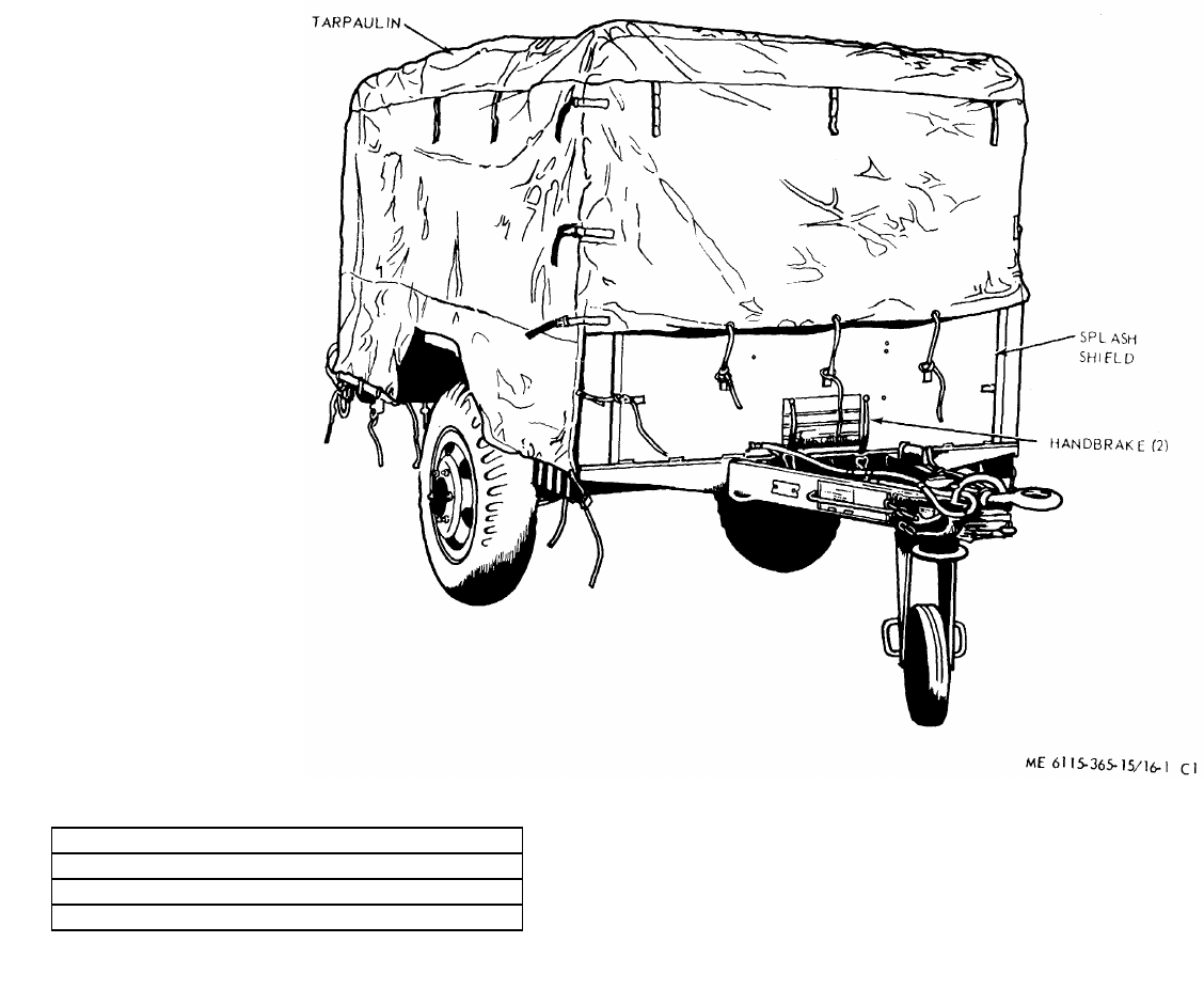
NOTE: ROLL UP TARPAULIN AND
REMOVE 2 BOLTS AND 2 NUTS
FROM TOP OF SPLASH SHIELD.
REMOVE SPLASH SHIELD BEFORE
OPERATING EQUIPMENT.
TM 5-6115-365-15
C1
SHIPPING DIMENSIONS
LENGTH 172 INCHES
WIDTH 83 INCHES
HEIGHT 66 INCHES
WEIGHT 2,540 POUNDS
Figure 16-1. PU-304C/MPQ-4, right front, 3/4 view.
16-2
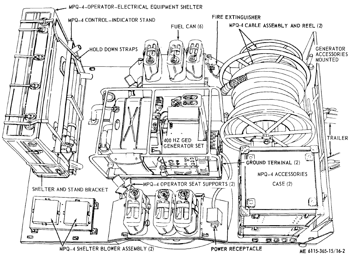
TM 5-6115-365-15
C1
Figure 16-2. PU-304C/MPQ-4 overall view showing radar equipment stowed.
16-3
TM 5-6115-365-15
C1
Section II. OPERATING INSTRUCTIONS
16-3. Setting-Up Instructions
a. Leveling.
(1) Locate the trailer on as level a surface as
possible in order for the generator sets IA) operate
efficiently.
(2) Set brakes and block wheels securely to
prevent any movement. Operate the handbrake at
weekly intervals to assure freedom of linkage.
(3) Pull leg support down and adjust length
for firm contact with ground.
Warning
Wheels must be blocked, brakes set,
and leg support down in support
position before attempting to roll up
the tarpaulin and before starting to
assemble or set up the equipment for
operation.
b. Preparation For Starting.
(1) Roll up tarpaulin, remove splash shield
and set it aside as shown in figure 16-3.
(2) Remove all loose auxiliary items and
anything else that might restrict the free circulation of air
through the trailer and around the generator set. There
should be a minimum of 25 inches of air space on all
sides of the generator. Caution
It is of foremost importance that
there be free circulation of air around
the generator set at all times during
operation. Inadequate ventilation is a
major cause of damage to the
equipment.
(3) Connect the load cable as shown in figure
16-4.
c. Grounding. Warning
Never operate the generator set until
it has been properly grounded.
Electrical defects in the load lines or
equipment can cause death by
electrocution when contact is made
with an ungrounded system.
(1) The generator set must be grounded prior
to operation. The ground may be any of three methods,
depending on the location and terrain:
(a) A ground rod driven to a depth of 8
feet.
(b) An underground metallic water
piping system.
(c) A metal plate (4 ft. sq) buried at a
depth of 4 feet.
(2) The ground lead must be No. 6 AWG
copper wire bolted or clamped to the rod, plate, or piping
system.
(3) Connect the other end of the ground lead
to the generator set ground terminal stud and connect
the generator to the ground terminal stud and connect
the generator to the ground terminal stud as shown in
figure 16-3.
d. Fuel Hose Connection. Connect the fuel hoses
as illustrated in figure 16-5.
Warning
Never operate the generator set in an
enclosed area unless the exhaust
gases are piped to the outside.
Inhalation of exhaust fumes will
result in serious illness or death.
16-4. Starting
a. Perform the setting-up and pre-starting
procedures (para 16-3).
b. Start the generator set as instructed in
TM 5-6115-450-15.
16-5. Stopping
Stop the generator set as instructed in
TM 56115-450-15.
16-6. Operation
a. Operate the generator set as instructed in
TM 5-6115-450-15.
b. Perform the fuel transfer procedure as instructed
in figure 16-5.
16-4
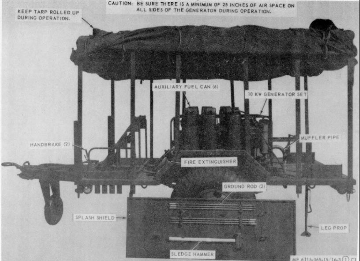
TM 5-6115-365-15
C1
Figure 16-3. PU-304C/MPQ-4 set up for operation 16-5
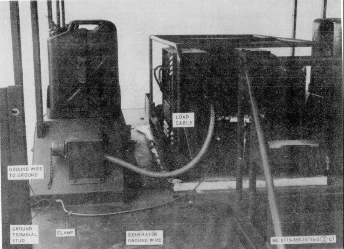
TM 5-6115-365-15
C1
Figure 16-3. Continued.
16-6
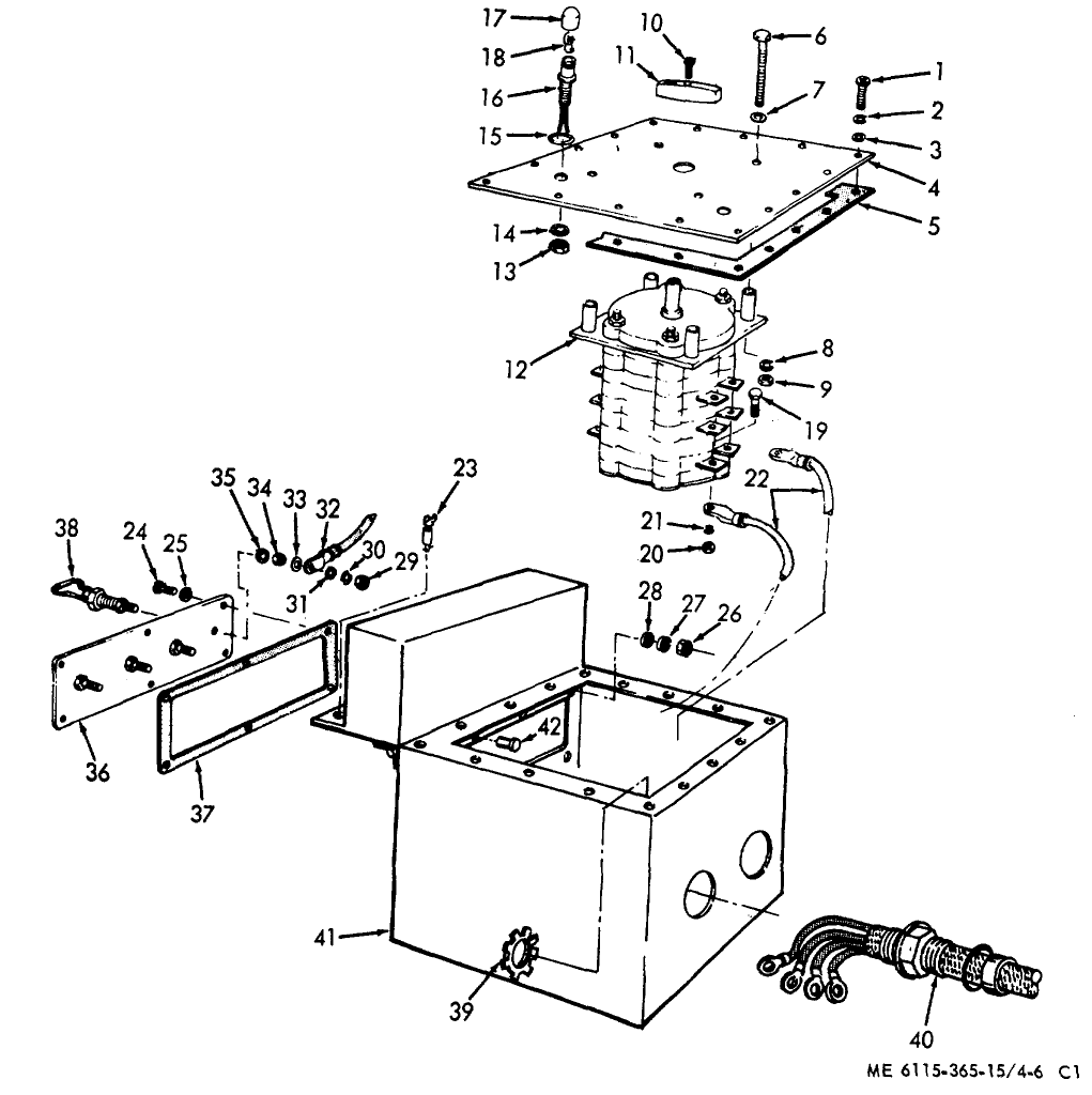
TM 5-6115-365-15
C1
Figure 16-4. Load cable connection diagram.
16-7
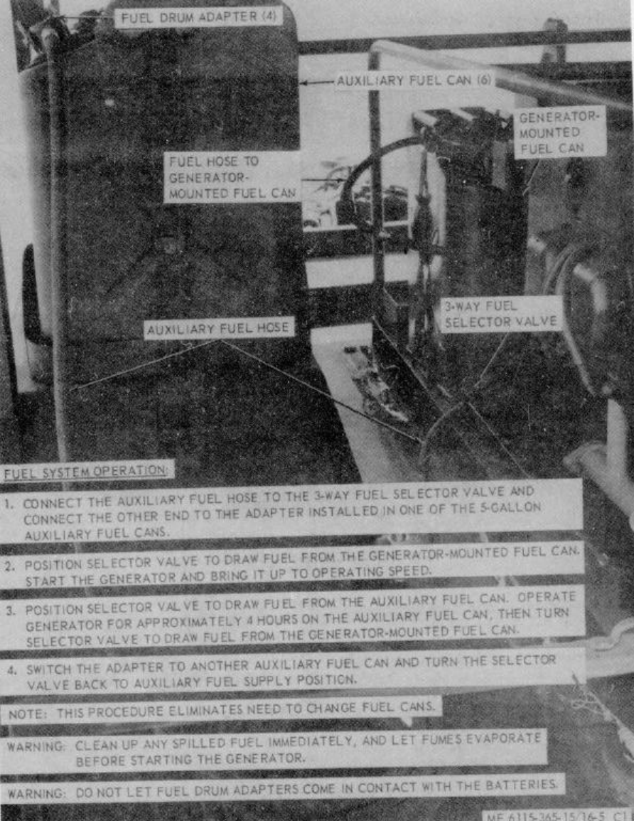
TM 5-6115-365-15
C1
Figure 16-5. Fuel system connection and transfer procedure.
16-8
TM 5-6115-365-15
C1
Section III. ORGANIZATIONAL MAINTENANCE INSTRUCTIONS
16-7. Ground Wires and Terminal Stud
a. Removal. Remove the ground wires from the
ground terminal stud and generator set as shown in
figure 16-3.
b. Installation. Install the ground terminal stud and
ground wires as shown in figure 16-3.
16-8. Tarpaulin, Roof Bows, and Leg Prop
a. Removal.
(1) Remove the tarpaulin from the unit.
(2) Pull out the pins that secure the roof bows
to the trailer bed and remove the bows.
(3) Remove the hardware that secures the leg
prop to the rear underside of the trailer bed and remove
the leg prop.
b. Cleaning and Inspection.
(1) Clean tarpaulin and bows with water and
detergent. Clean leg prop with approved cleaning
solvent. Dry thoroughly.
(2) Inspect tarpaulin for tears, holes, broken
or missing ropes and straps, and other defects. Inspect
bows and leg prop for cracks, bends, and other defects.
c. Installation.
(1) Mount the leg prop to the underside of the
trailer bed and secure with mounting hardware.
(2) Install the roof bows in the trailer bed and
secure with pins. Install the tarpaulin and secure in
desired position.
16-9. Stowage Racks and Brackets and Straps
a. General. PU-304C/MPQ-4 is equipped with
stowage racks and brackets for the Radar Equipment.
Location of these brackets is shown in figure 16-3.
b. Removal. Remove the mounting hardware that
secures the racks and brackets to the trailer bed and
remove racks and brackets.
c. Cleaning, Inspection, and Repair.
(1) Clean with approved cleaning solvent and
dry thoroughly.
(2) Inspect for breaks, bends, dents and
missing or defective hardware. Inspect straps for wear
and other damage.
(3) Straighten minor bends, replace defective
straps and missing hardware, and replace a defective
bracket that cannot be made serviceable.
d. Installation. Secure the stowage racks and
brackets to the trailer bed with mounting hardware.
Section IV. DIRECT AND GENERAL SUPPORT AND DEPOT MAINTENANCE INSTRUCTIONS
16-10. Generator Set
a. Removal. Refer to figure 16-6 as a guide and
perform the following steps:
(1) Disconnect fuel lines.
(2) Disconnect electrical leads and load
cable. (3) Disconnect oil drain adapter.
(4) Remove 2 bolts and nuts from muffler pipe
and remove pipe from trailer.
(5) Remove the four bolts that secure the
generator set to the trailer and remove the generator set.
b. Installation. Use figure 16-6 as a guide and
perform the following steps:
(1) Secure the generator set to the trailer bed
with 4 bolts.
(2) Secure muffler pipe to trailer bed with 2
bolts and 2 nuts.
(3) Connect the oil drain adapter.
(4) Connect the electrical leads and cable.
(5) Connect fuel lines.
16-11. Tarpaulin, Roof Bows, and Leg Prop
a. Removal. Remove tarpaulin, bows, and leg
prop (para 16-8).
b. Repair.
(1) Patch or sew rips and tears in the
tarpaulin. Replace damaged or missing straps or ropes.
Replace a tarpaulin that is too badly damaged to be
repaired.
16-9
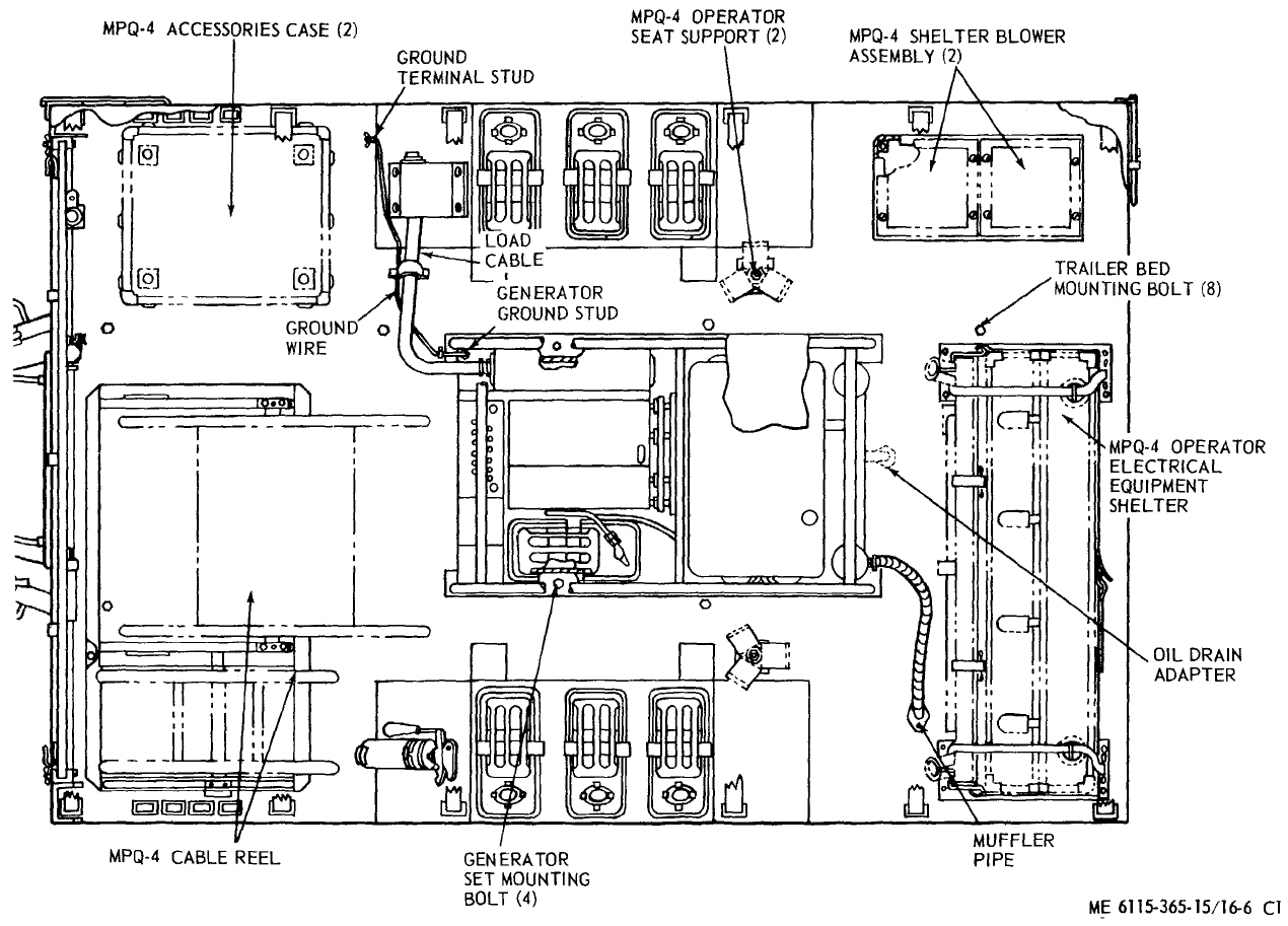
TM 5-6115-365-15
C1
Figure 16-6. PU-304C/MPQ-4 overall component location diagram
16-10
TM 5-6115-365-15
C1
(2) Weld minor cracks or breaks in the bows
or leg prop. Straighten bent bows where possible.
Replace defective or missing hardware. Replace bows
or leg prop that are damaged beyond repair.
c. Installation. Install tarpaulin, roof bows, and leg
prop (para 16-8).
16-12. Trailer Bed
a. Removal.
(1) Remove tarpaulin, roof bows, and leg prop
(para 16-8).
(2) Remove the generator set (para 16-10).
(3) Loosen straps and remove auxiliary fuel
cans from trailer.
(4) Remove 8 bolts from the top surface of
the trailer bed and 12 bolts from the underside that
secure the gussets to the trailer.
(5) Disconnect the electrical leads from the
trailer lights.
(6) Remove the trailer bed from the trailer.
b. Cleaning, Inspection, and Repair.
(1) Clean trailer bed with approved
cleaning solvent and dry.
(2) Inspect for broken welds, bends, and
dents, and any other damage that prevents proper
assembly of the unit.
(3) Weld cracks and breaks, and
straighten dents and bends where possible.
(4) Replace a trailer bed that is damaged
beyond repair.
c. Installation.
(1) Install the trailer bed on the trailer and
secure in position with 12 bolts on the underside and 8
bolts on the top.
(2) Connect wiring to trailer lights.
(3) Install the generator set (para 16-10).
(4) Install auxiliary fuel cans on trailer and
secure with straps.
(5) Install leg prop, roof bows, and tarpaulin
(para 16-11).
16-11
(1) (2) (3) (4) (5) (6) (7)
FEDERAL DESCRIPTION UNIT QTY 15-DAY ORGANIZATIONAL ILLUS-
SMR STOCK OF INC MAINTENANCE ALW RATION
CODE NUMBER USABLE MEAS IN (a) (b) (c) (d) (a) (b)
ON UNIT FIG ITEM
REF NUMBER & MFG CODE CODE 1-5 6-20 21-50 51-100 NO. NO.
TM 5-6115-365-15
C1
PART I
REPAIR PARTS FOR ORGANIZATIONAL MAINTENANCE
00001 GROUP 01 - ENGINE
00002 0106 - ENGINE LUBRICATION SYSTEM
O5320-282-7822 NUT, UNION: oil drain hose EA 1****
00003
O4730-766-7908 UNION, FLARED TUBE: oil drain EA 1****
00004
O5310-754-2005 WASHER, LOCK: oil drain hose EA 1****
00005
00006 GROUP 15 - FRAME, TOWING ATTACHMENTS AND DRAWBARS
00007 1501 - FRAME ASSEMBLY
12 O5340-999-6277 BRACKET ASSEMBLY EA 1
00008 13214E1214 (97403)
X2 OBRACKET, SHELTER EA 1
00009 13216E7442 (97403)
X2 OCLAMP: ground round EA 4
00010 13212E3617-1 (97403)
X2 OCLAMP, PLAIN: support loop EA 2
00011 MS21103D3 (96906)
X2 O5340-914-2578 CLIP, SPRING EA 1
00012 132141213-1 (97403)
X2 O7248-920-5328 HOLDER, SPOUT EA 1
00013 13214E3553-2 (97403)
12 ONUT, HEXAGON, SELF-LOCKING: 10 x 32 screw EA 2
00014 MS21044N3 (96906)
O5310-225-6993 NUT, SELF-LOCKING, HEXAGON: 1-2 x 13 EA 8****
00015
O5310-088-1251 NUT, SELF-LOCKING, HEXAGON: 1-4 x 20 EA 2****
00016
O5310-088-1251 NUT, SELF-LOCKING, HEXAGON: 1-4x 20 EA 4****
00017
O5310-088-1251 NUT, SELF-LOCKING, HEXAGON: 1-4 x 20, screw EA 4****
00018
O5310-088-1251 NUT, SELF-LOCKING, HEXAGON: 1-4 x 20, screw EA 4****
00019
O5310-088-1251 NUT, SELF-LOCKING, HEXAGON: 1-4x 20 EA 4****
00020
O5310-088-1251 NUT, SELF-LOCKING, HEXAGON: 1-4 x 20, screw EA 1****
00021
O5310-088-1251 NUT, SELF-LOCKING, HEXAGON: 1-4 x 20 EA 8****
00022
X2 ONUT, SELF-LOCKING, HEXAGON: 3-4 x 10, screw EA 2
00023 MS51922-57 (96906)
O5310-984-3806 NUT, SELF-LOCKING, HEXAGON:5-16 x 18 EA 2****
00024
O5310-984-3806 NUT, SELF-LOCKING, HEXAGON: 5-16 x 18 EA 10 ****
00025
X2 ORACK, BLOWER, HOUSING EA 1
00026 13216E7437 (97403)
X2 ORACK, CABLE REEL EA 1
00027 13216E7439 (97403)
X2 OSCREW, CAP, HEXAGON HEAD: 1-2 x 13 x 1-1/4 EA 8
00028 MS90725-.111 (96906)
O5305-068-0501 SCREW, CAP, HEXAGON HEAD: 1-4 x 20 x 5-8 EA 1****
00029
O5305-068-0501 SCREW, CAP, HEXAGON HEAD: 1-4 x 20 x 5-8 EA 2****
00030
X2 OSCREW, CAP, HEXAGON HEAD: 1-4 x 20 x 7-8 EA 4
00031 MS90725-7 (96906)
X2 OSCREW, CAP, HEXAGON HEAD: 1-4 x 20 x 7-8 EA 4
00032 MS90725-7 (96906)
16-12
(1) (2) (3) (4) (5) (6) (7)
FEDERAL DESCRIPTION UNIT QTY 15-DAY ORGANIZATIONAL ILLUS-
SMR STOCK OF INC MAINTENANCE ALW RATION
CODE NUMBER USABLE MEAS IN (a) (b) (c) (d) (a) (b)
ON UNIT FIG ITEM
REF NUMBER & MFG CODE CODE 1-5 6-20 21-50 51-100 NO. NO.
TM 5-6115-365-15
C1
X2 OSCREW, CAP, HEXAGON HEAD: 1-4 x 20 x 7-8 EA 4
00033 MS90725-7 (96906)
X2 OSCREW, CAP, HEXAGON HEAD: 1-4 x 20 x 7-8 EA 4
00034 MS90725-7 (96906)
O5306-225-8499 SCREW, CAP, HEXAGON: 5-16 x 18 x 1 EA 10 ****
00035
X2 OSCREW, CAP, HEXAGON HEAD: 5-16 x 18 x 3-4 EA 2
00036 MS90725-32 (96906)
X2 OSCREW, MACHINE: flat head EA 8
00037 MS35190-289 (96906)
X2 OSCREW, MACHINE: pan head EA 2
00038 MS35207-266 (96906)
X2 OSETSCREW, HEXAGON: socket, 3-8 x 16 x 1 in. EA 2
00039 MS51963-107 (96906)
X2 OSTUD: 3-4 x 10, special EA 2
00040 13216E7438 (97403)
O5310-809-5998 WASHER, FLAT: round, 1-2 In. screw EA 8****
00041
O5310-809-4058 WASHER, FLAT: round, 1-4 in. screw EA 1****
00042
O5310-809-4058 WASHER, FLAT: round, 1-4 in. screw EA 4****
00043
O5310-809-4058 WASHER, FLAT: round, 1-4 in. screw EA 2****
00044
O5310-809-4058 WASHER, FLAT: round, 1-4 x 20 screw EA 4****
00045
O5310-809-4058 WASHER, FLAT: round, 1-4 x 20 screw EA 4****
00046
O5310-809-4058 WASHER, FLAT: round, 1-4 x 20 screw EA 4****
00047
O5310-809-4058 WASHER, FLAT: round, 1-4 in. screw EA 8****
00048
O5310-809-8546 WASHER, FLAT: round, 10 x 32 screw EA 2****
00049
X2 OWASHER, FLAT: round, 3/4 in. screw EA 2
00050 MS27183-23 (96906)
O5310-081-4219 WASHER, FLAT: round, 5-16 screw EA 12 ****
00051
00052 GROUP 18 - BODY , CAB, HOOD AND HULL
00053 1810 - CARGO BODY
X2 OBOLT, HEXAGON HEAD: 11 x 6-1/2 in. lg EA 2
00054 FFB575 (97403)
O5310-269-4040 NUT, SELF-LOCKING, HEXAGON:5/8 x 11 bolt EA 8****
0055
O5305-724-5911 SCREW, CAP, HEXAGON HEAD:5/8 x 11 x 1-3/4 EA 6****
00056
O5310-823-8803 WASHER, FLAT: round, 5/8 in. bolt EA 8****
00057
00058 GROUP 22 - BODY CHASSIS OR HULL, AND ACCESSORY ITEMS
00059 2201 - CANVAS ITEMS
PO2540-926-1003 BOW, TRAILER, TARPAULIN: 55.75 in. height EA 2****
00060 13212E3597-2 (97403)
PO2540-924-8478 BOW, TRAILER, TARPAULIN: 68 in. height EA 4****
00061 13212E3597-1 (97403)
O5310-080-8495 NUT, PLAIN, WING: 1-4 x 20 screw EA 2****
00062
O5310-087-4652 NUT, SELF-LOCKING, HEXAGON: 3-8 x 16 screw EA 12 ****
00063
X2 OSCREW, CAP, HEXAGON HEAD: 1-4 x 20 x 2 in. EA 2
00064 MS35307-314 (96906)
O5305-269-3211 SCREW, CAP, HEXAGON HEAD: 3-8 x 16 x 1 IN. EA 16 ****
00065
X2 OSHIELD EA 1
00066 13216E7433 (97403)
16-13
(1) (2) (3) (4) (5) (6) (7)
FEDERAL DESCRIPTION UNIT QTY 15-DAY ORGANIZATIONAL ILLUS-
SMR STOCK OF INC MAINTENANCE ALW RATION
CODE NUMBER USABLE MEAS IN (a) (b) (c) (d) (a) (b)
ON UNIT FIG ITEM
REF NUMBER & MFG CODE CODE 1-5 6-20 21-50 51-100 NO. NO.
TM 5-6115-365-15
C1
X2 OSHIM (As required) EA
00067 13212E3590 (97403)
PO R TARPAULIN EA 1****
00068 13216E7434 (97403)
X2 OBUCKLE: spring action EA 8
00069 MS51929-2 (96906)
X2 OCLIP, END, STRAP EA 13
00070 MILC496 (81349)
O5310-809-4058 WASHER, FLAT: round, 1-4 x 20 screw EA 4
00071
X2 OWASHER, FLAT: round, 3-8 x 16 screw EA 16
00072 MS27183-14 (96906)
O5310-933-8121 WASHER, LOCK: helical, 1-4 x 20 screw EA 2****
00073
X2 OWASHER, LOCK: helical, 3-8 x 16 screw EA 4
00074 MS35338-46 (96906)
00075 2202 - ACCESSORY ITEMS
X2 OAXLE, CABLE REEL EA 1
00076 13216E7447 (97403)
PO3120-939-6692 HEARING EA 2****
00077 13214E1294 (97403)
X2 O2590-473-6331 BRACKET ASSEMBLY: liquid container EA 6
00078 MS353052-1 (96906)
X2 O7240-222-3088 CAN, GASOLINE: Military 5 gal EA 6
00079 MILC1283 (81349)
X2 OCLAMP EA 2
00080 13216E7435 (97403)
X2 OCLAMP EA 1
00081 13216E7436 (97403)
PC5120-203-4656 HAMMER: hand type X class 1 EA 1****
00082 GGGH86 (81348)
O5310-088-1251 NUT, SELF-LOCKING, HEXAGON: 1-4 x 20 screw EA 4****
00083
O5310-088-1251 NUT, SELF-LOCKING, HEXAGON: 1-4 x 20 screw EA 8****
00084
O5310-087-4652 NUT, SELF-LOCKING, HEXAGON: 3-8 x 16 EA 24 ****
00085
PO9905-202-3639 REFLECTOR: amber clearance indicator EA 2****
00086 MS35387-2 (96906)
PO9905-205-2795 REFLECTOR: red clearance indicator EA 4****
00087 MS35387-1 (96906)
PC5975-878-3791 ROD: ground, Type 2, Style 2 E2****
00088 MILR11461 (81349)
X2 OSCREW, CAP, HEXAGON HEAD: 1-4 x 20 x 1-2 lg EA 4
00089 MS90725-3 (96906)
X2 OSCREW, CAP, HEXAGON HEAD: 1-4 x 20 x 1-1/2 EA 4
00090 MS90725-12 (96906)
O5305-071-2241 SCREW, CAP, HEXAGON HEAD: 1-4 x 20 x 1-1/4 EA 2****
00091
X2 OSCREW, CAP HEXAGON HEAD: 1-4 x 20 x 1-2 lg EA 8
00092 MS90725-3 (96906)
O5305-269-3211 SCREW, CAP, HEXAGON HEAD: 3-8 x 16 x 1 EA 24 ****
00093
X2 O7240-177-6154 SPOUT, CAN: flexible EA 1
00094 MILS1285 (81349)
O5310-809-4058 WASHER, FLAT: round, 1-4 in. screw EA 4****
00095
O5310-809-4058 WASHER, FLAT: round, 1-4 x 20 screw EA 8****
00096
16-14

(1) (2) (3) (4) (5) (6) (7)
FEDERAL DESCRIPTION UNIT QTY 15-DAY ORGANIZATIONAL ILLUS-
SMR STOCK OF INC MAINTENANCE ALW RATION
CODE NUMBER USABLE MEAS IN (a) (b) (c) (d) (a) (b)
ON UNIT FIG ITEM
REF NUMBER & MFG CODE CODE 1-5 6-20 21-50 51-100 NO. NO.
TM 5-6115-365-15
C1
O5310-809-4061 WASHER, FLAT: round, 3-8 screw EA 24 ****
00097
X2 OWASHER, LOCK: helical, 1-4 IN. EA 2
00098 MS35338-44 (96906)
X2 OWASHER, LOCK: helical, 1/4 EA 4
00099 MS35338-44 (96906)
00100 2210 - DATA PLATES
12 OPLATE, IDENTIFICATION EA 1
00101 13205E4918 (97403)
X2 OPLATE, IDENTIFICATION EA 1
00102 13205E4916-27 (97403)
00103 GROUP 29 - AUXILIARY GENERATOR AND ENGINE AND CONTROLS
00104 2941 - ENGINE MUFFLER, EXHAUST AND TAIL PIPES
O5310-088-1251 NUT, SELF-LOCKING, HEXAGON:1-4 x.20 EA 2****
00105
O5305-225-3839 SCREW, CAP, HEXAGON: 1-4 x 20 x 1 EA 2****
00106
O5310-809-4058 WASHER, FLAT: round, 1-4 x 20, screw EA 2****
00107
00108 GROUP 40 - ELECTRIC MOTORS AND GENERATORS
00109 4000 - GENERATOR ASSEMBLY
O5310-269-4040 NUT, SELF-LOCKING, HEXAGON: 5-8 x 11 EA 4****
00110
X2 OSCREW, CAP, HEXAGON BEAD: 5-16 x 11 x 1-3/8 EA 4
00111 MS90725-161 (96906)
O5310-823-8803 WASHER, FLAT: round, 5-8, screw EA 4****
00112
00113 4019 - RADIO INTERFERENCE SUPPRESSION
X2 ONUT, PLAIN, HEXAGON BREAKERS: 3-8 x 16 EA 2
00114 FFN836 (81348)
X2 ONUT, PLAIN, WING BREAKERS: 3-8 x 16 EA 1
00115 MS35425-28 (96906)
X2 OSTUD: 3/8 x 162-1-2 in. lg EA 1
00116 13214E1223 (96906)
X2 OWASHER, FLAT: round, 3/8 in. screw EA 3
00117 AN961-616 (88044)
O5310-913-9776 WASHER, LOCK, FLAT: external tooth, 3-8 EA 3****
00118
00119 GROUP 42 - ELECTRICAL EQUIPMENT
00120 4216 - MISCELLANEOUS WIRING AND FITTINGS
O5310-088-1251 NUT, SELF-LOCKING, HEXAGON: 1-4 x 20 screw EA 4****
00121
O5305-225-3839 SCREW, CAP, HEXAGON HEAD: 1-4 x 20 EA 4****
00122
O5310-809-4058 WASHER, FLAT: round, 1-4 x 20 screw EA 4****
00123
00124 GROUP 76 - FIRE FIGHTING EQUIPMENT COMPONENTS
00125 7638 - PORTABLE FIRE FIGHTING EQUIPMENT
PC4210-555-8837 EXTINGUISHER, FIRE: w/bracket EA 1****
00126 MILE52031 (81349)
00127 GROUP 95 - GENERAL USE STANDARDIZED PARTS
00128 9501 - HARDWARE SUPPLIES AND BULK MATERIAL, COMMON
POWEBBING, TEXTILE, NYLON: 1 in. wide FT ****
00129 MILW4088 (81349)
16-15
(1) (2) (3) (4) (5) (6) (7) (8) (9) (10)
DESCRIPTION 1-YR
DEPOT
QTY 30-DAY DS MAINT 30-DAY GS MAINT ALW
PER
MAINT
ALW ILLUS-
TRATION
FEDERAL USABLE
UNIT
INC ALLOWANCE ALLOWANCE 100 PER (a) (b)
SMR
CODE STOCK
NUMBER
ON
REF NUMBER & MFR CODE CODE OF
MEAS IN
UNIT (a)
1-20 (b)
21-50 (c)
51-100 (a)
1-20 (b)
21-50 (c)
51-100
EQUIP
CNTGCY 100
EQUIP
FIG.
NO.
ITEM
NO.
TM 5-6115-365-15
C1
PART II
REPAIR PARTS FOR DS, GS,
AND DEPOT MAINTENANCE
00001 GROUP 01 - ENGINE
00002 0106 - ENGINE LUBRICATION SYSTEM
O5320-282-7822NUT, UNION: oil drain hose EA 1******* *
00003
O4730-766-7908 UNION, FLARED TUBE:oil drain EA 1******* *
00004
O5310-754-2005 WASHER, LOCK: oil drain hose EA 1******* *
00005
00006 GROUP 15 - FRAME,
TOWING ATTACHMENTS AND DRAWBARS
00007 1501 - FRAME ASSEMBLY
X2 O5340-999-6277 BRACKET ASSEMBLY EA 1
00008 13214E1214 (97403)
X2 FBRACKET: receptacle EA 1
00009 13216E7449 (97403)
X2 OBRACKET, SHELTER EA 1
00010 13216E7442 (97403)
X2 OCLAMP: ground round EA 4
00011 13212E3617-1 (97403)
X2 OCLAMP, PLAIN: support loop EA 2
00012 MS21103D3 (96906)
X2 O5340-914-2578 CLIP, SPRING EA 1
00013 13214E1213-1 (97403)
X2 O7240-920-5328 HOLIER, SPOUT EA 1
00014 13212E3553-2 (97403)
X2 ONUT, HEXAGON, SELF-LOCKING: 10X32 screw EA 2
00015 MS21044N3 (96906)
O5310-225-6993 NUT, SELF-LOCKINGHEXAGON: 1-2X13 EA 8******* *
00016
O5310-088-1251 NUT, SELF-LOCKING, HEXAGON: 1-4X20 EA 2******* *
00017
O5310-088-1251 NUT, SELF-LOCKING, HEXAGON: 1-4X20 EA 4******* *
00018
O5310-088-1251 NUT, SELF-LOCKING, HEXAGON: 1-4X20, EA 4******* *
00019 screw
O5310-088-1251 NUT, SELF-LOCKING, HEXAGON: 1-4X20, EA 4******* *
00020 screw
O5310-088-1251 NUT, SELF-LOCKING, HEXAGON: 1-4X20 EA 4******* *
00021
O5310-088-1251 NUT, SELF-LOCKING, HEXAGON: 1-4X20, EA 1******* *
00022 screw
O5310-088-1251 NUT, SELF-LOCKING, HEXAGON: 1-4X20 EA 8******* *
00023
X2 ONUT, SELF-LOCKING, HEXAGON: 3-4X10, EA 2
00024 screw
MS51922-57 (96906)
O5310-984-3806 NUT, SELF-LOCKING, HEXAGON: 5-16X18 EA 2******* *
00025
O5310-984-3806 NUT, SELF-LOCKING, HEXAGON: 5-16X18 EA 10 ******* *
00026
12 ORACK, BLOWER, HOUSING EA 1
00027 13216E7437 (97403)
12 ORACK, CABLE REEL EA 1
00028 13216E7439 (97403)
16-16
(1) (2) (3) (4) (5) (6) (7) (8) (9) (10)
DESCRIPTION 1-YR
DEPOT
QTY
30-DAY DS MAINT
30-DAY GS MAINT
ALW
PER MAINT
ALW ILLUS-
TRATION
FEDERAL USABLE UNIT INC ALLOWANCE ALLOWANCE 100 PER (a) (b)
SMR
CODE STOCK
NUMBER
ON
REF NUMBER & MFR CODE CODE OF
MEAS
IN
UNIT (a)
1-20 (b)
21-50 (c)
51-100 (a)
1-20 (b)
21-50 (c)
51-100
EQUIP
CNTGCY
100
EQUIP FIG.
NO. ITEM
NO.
TM 5-6115-365-15
C1
X2 OSCREW, CAP, HEXAGON HEAD: 1-2X13X1-1/4 EA 8
00029 MS90725-111 (96906)
O5305-068-0501 SCREW, CAP, HEXAGON HEAD: 1-4X20X5-8 EA 1******* *
00030
O5305-068-0501 SCREW, CAP, HEXAGON HEAD: 1-4X20X5-8 EA 2******* *
00031
X2 OSCREW, CAP, HEXAGON HEAD: 1-4X20X7-8 EA 4
00032 MS90725-7 (96906)
X2 OSCREW, CAP, HEXAGON HEAD: 1-4X20X7-8 EA 4
00033 MS90725-7 (96906)
X2 OSCREW, CAP, HEXAGON HEAD: 1-4X20X7-8 EA 4
00034 MS90725-7 (96906)
X2 OSCREW, CAP, HEXAGON HEAD: 1-4X20X7-8 EA 4
00035 MS90725-7 (96906)
O5306-225-8499 SCREW, CAP, HEXAGON: 5-16X18X1 EA 10 ******* *
00036
X2 OSCREW, CAP, HEXAGON HEAD: 5-16X18X3-4 EA 2
00037 MS90725-32 (96906)
X2 OSCREW, MACHINE: flat head EA 8
00038 MS35190-289 (96906)
X2 OSCREW, MACHINE: pan head EA 2
00039 MS35207-266 (96906)
X2 OSETSCREW, HEXAGON:socket, 3-X16X1 IN. EA 2
00040 MS51963-107 (96906)
X2 OSTUD: 3-4X10, special EA 2
00041 13216E7438 (97403)
O5310-809-5998 WASHER, FLAT:round, 1-2 in. screw EA 8******* *
00042
O5310-809-4058 WASHER, FLAT:round, 1-4 in. screw EA 1******* *
00043
O5310-809-4058 WASHER, FLAT:round, 1-4 in. screw EA 4******* *
00044
O5310-809-4058 WASHER, FLAT:round, 1-4 in. screw EA 2******* *
000A5
O5310-809-4058 WASHER, FLAT:round, 1-4X20 screw EA 4******* *
00046
O5310-809-4058 WASHER, FLAT: round, 1-4X20 screw EA 4******* *
00047
O5310-809-4058 WASHER, FLAT:round, 1-4X20 screw EA 4******* *
00048
O5310-809-4058 WASHER, FLAT:round, 1-4 in. screw EA 8******* *
00049
O5310-809-8546 WASHER, FLAT:round, 10X32 screw EA 2******* *
00050
X2 OWASHER, FLAT round, 3/4 in. screw EA 2
00051 MS27183-23 (96906)
O5310-081-4219 WASHER, FLAT: round, 5-16 screw EA 12 ******* *
00052
00053 GROUP 18 - BODY, CAB,
HOOD AND HULL
00054 1810 - CARGO BODY
X2 DR BODY, TRAILER EA 1
00055 13216E7432 (97403)
X2 OBOLT, HEXAGON HEAD: 11X6-1/2 in. lg EA 2
00056 FFB575 (97403)
O5310-269-4040 NUT, SELF-LOCKING, HEXAGON 5/8X11 bolt EA 8******* *
00057
O5305-724-5911 SCREW, CAP, HEXAGON HEAD: 5/8X11X1-3/4 EA 6******* *
00058
X2 DR 2330-141-8052 TRAILER: M103A3 modified EA 1
00059 MS530291-1 (96906)
O5310-823-8803 WASHER, FLAT: round, 5/8 in. bolt EA 8******* *
00060
16-17

(1) (2) (3) (4) (5) (6) (7) (8) (9) (10)
DESCRIPTION 1-YR
DEPOT
QTY 30-DAY DS MAINT 30-DAY GS MAINT ALW
PER
MAINT
ALW ILLUS-
TRATION
FEDERAL USABLE
UNIT
INC ALLOWANCE ALLOWANCE 100 PER (a) (b)
SMR
CODE STOCK
NUMBER
ON
REF NUMBER & MFR CODE CODE OF
MEAS IN
UNIT (a)
1-20 (b)
21-50 (c)
51-100 (a)
1-20 (b)
21-50 (c)
51-100
EQUIP
CNTGCY 100
EQUIP
FIG.
NO.
ITEM
NO.
TM 5-6115-365-15
C1
00061 GROUP 22 - BODY CHASSIS OR HULL,
AND ACCESSORY ITEMS
00062 2201 - CANVAS ITEMS
PO2540-926-1003 BOW, TRAILER, TARPAULIN: 55.75 in. height EA 2******4 4
00063 13212E3597-2 (97403)
PO2540-924-8478 BOW, TRAILER, TARPAULIN: 68 in. height EA 4* * 2* * 2 8 8
00064 13212E3597-1 (97403)
O5310-080-8495 NUT, PLAIN, WING: 1-4X20 screw EA 2******* *
00065
O5310-087-4652 NUT, SELF-LOCKING, HEXAGON: 3-8X16 screw EA 12 ******* *
00066
X2 OSCREW, CAP, HEXAGON HEAD: 1-4X20X2 IN. EA 2
00067 MS35307-314 (96906)
O5305-269-3211 SCREW, CAP, HEXAGON HEAD: 3-8X16X1 IN. EA 16 ******* *
00068
X2 OSHIELD EA 1
00069 13216E7433 (97403)
X2 OSHIM (As required) EA
00070 13212E3590 (97403)
P O R TARPAULIN EA 1*2 2 *2 2 13 13
00071 13216E7434 (97403)
X2 OBUCKLE: spring action EA 8
00072 MS51929-2 (96906)
X2 OCLIP, END, STRAP EA 13
00073 MILC496 (81349)
MDSTRAP, WEBBING EA 2
00074 13216E7443 (97403)
MANUFACTURE FROM:
PD5340-922-5653 WEBBING, TEXTILE: nylon 1 in. wide FT SEE GRP 9501
00075 MILW4088 (81349)
MDSTRAP, WEBBING: 43 in. lg EA 2
00076 13216E7445-1 (97403)
MANUFACTURE FROM:
PD5340-922-5653 WEBBING, TEXT-LE: nylon 1 in. wide FT SEE GRP 9501
00077 MILW4088 (81349)
MDSTRAP, WEBBING:43 in. lg EA 1
00078 13216E7444-1 (97403)
MANUFACTURE FROM:
PDWEBBING, TEXTILE: nylon 1 in. wide FT SEE GRP 9501
00079 MILW4088 (81349)
MDSTRAP, WEBBING:55 in. lg EA 1
00080 13216E7445-2 (97403)
MANUFACTURE FROM:
PDWEBBING, TEXTILE: nylon 1 in. wide FT SEE GRP 9501
00081 MILW4088 (81349)
MDSTRAP, WEBBING: 77 in. lg EA 2
00082 13216E7444-2 (97403)
MANUFACTURE FROM:
PDWEBBING, TEXTILE: nylon 1 in. wide FT SEE GRP 9501
00083 MILW4088 (81349)
O5310-809-4058 WASHER, FLAT: round, 1-4X20 screw EA 4******* *
00084
X2 OWASHER, FLAT:round, 3-8X16 screw EA 16
00085 MS27183-14 (96906)
O5310-933-8121 WASHER, LOCK: helical, 1-4X20 screw EA 2******* *
00086
X2 OWASHER, LOCK: helical, 3-8X16 screw EA 4
00087 MS35338-46 (96906)
16-18

(1) (2) (3) (4) (5) (6) (7) (8) (9) (10)
DESCRIPTION 1-YR
DEPOT
QTY 30-DAY DS MAINT 30-DAY GS MAINT ALW
PER
MAINT
ALW ILLUS-
TRATION
FEDERAL USABLE
UNIT
INC ALLOWANCE ALLOWANCE 100 PER (a) (b)
SMR
CODE STOCK
NUMBER
ON
REF NUMBER & MFR CODE CODE OF
MEAS IN
UNIT (a)
1-20 (b)
21-50 (c)
51-100 (a)
1-20 (b)
21-50 (c)
51-100
EQUIP
CNTGCY 100
EQUIP
FIG.
NO.
ITEM
NO.
TM 5-6115-365-15
C1
00088 2202 - ACCESSORY ITEMS
X2 OAXLE, CABLE REEL EA 1
00089 13216E7447 (97403)
PO3120-939-6692 HEARING EA 2* * 2* * 2 10 10
00090 13214E1294 (97403)
X2 O2590-473-6331 BRACKET ASSEMBLY: liquid container EA 6
00091 553052-1 (96906)
X2 O7240-222-3088 CAN, GASOLINE: Military 5 gal. EA 6
00092 MILC1283 (81349)
X2 OCLAMP EA 2
00093 13216E7435 (97403)
X2 OCLAMP EA 1
00094 13216E7436 (97403)
PC5120-203-4656 HAMMER: hand type X class 1 EA 1* * 2* * 2 10 10
00095 GGGH86 (81348)
O5310-088-1251 NUT, SELF-LOCKING, HEXAGON: 1-4X20 screw EA 4******* *
00096
O5310-088-1251 NUT, SELF-LOCKING, HEXAGON: 1-4X20 screw EA 8******* *
00097
O5310-087-4652 NUT, SELF-LOCKING, HEXAGON: 3-8X16 EA 24 ******* *
00098
PO9905-202-3639 REFLECTOR:amber clearance indicator EA 2******6 6
00099 MS35387-2 (96906)
PO9905-205-2795 REFLECTOR: red clearance indicator EA 4*2 2 *2 2 12 12
00100 MS35387-1 (96906)
PC5975-878-3791 ROD: ground, Type 2, Style 2 EA 2* * 2* * 2 10 10
00101 MILR11461 (81349)
12 OSCREW, CAP, HEXAGON HEAD: 1-4X20X1-2 lg EA 4
00102 MS90725-3 (969o6)
X2 OSCREW, CAP, HEXAGON HEAD: 1-4X20X1-1/2 EA 4
00103 MS90725-12 (96906)
O5305-071-2241 SCREW, CAP, HEXAGON HEAD: 1-4X20X1-1/4 EA 2******* *
00104
X2 OSCREW, CAP, HEXAGON HEAD: 1-4X20X1-2 lg EA 8
00105 MS90725-3 (96906)
O5305-269-3211 SCREW, CAP, HEXAGON HEAD: 3-8X16X1 EA 24 ******* *
00106
X2 O7240-177-6154 SPOUT, CAN: flexible EA 1
00107 MILS1285 (81349)
O5310-809-4058 WASHER, FLAT: round, 1-4 in. screw EA 4******* *
00108
O5310-809-4058 WASHER, FLAT: round, 1-4X20 screw EA 8******* *
00109
O5310-809-4061 WASHER, FLAT: round, 3-8 screw EA 24 ******* *
00110
X2 OWASHER, LOCK: helical, 1-4 IN. EA 2
00111 MS35338-44 (96906)
X2 OWASHER, LOCK: helical, 1/4 EA 4
00112 MS35338-44 (96906)
00113 2210 - DATA PLATES
X2 OPLATE, IDENTIFICATION EA 1
00114 13205E4918 (96906)
X2 OPLATE, IDENTIFICATION EA 1
00115 13205E4916-27 (97403)
16-19

(1) (2) (3) (4) (5) (6) (7) (8) (9) (10)
DESCRIPTION 1-YR
DEPOT
QTY 30-DAY DS MAINT 30-DAY GS MAINT ALW
PER
MAINT
ALW ILLUS-
TRATION
FEDERAL USABLE
UNIT
INC ALLOWANCE ALLOWANCE 100 PER (a) (b)
SMR
CODE STOCK
NUMBER
ON
REF NUMBER & MFR CODE CODE OF
MEAS IN
UNIT (a)
1-20 (b)
21-50 (c)
51-100 (a)
1-20 (b)
21-50 (c)
51-100
EQUIP
CNTGCY 100
EQUIP
FIG.
NO.
ITEM
NO.
TM 5-6115-365-15
C1
00116 GROUP 29 - AUXILIARY GENERATOR AND
ENGINE AND CONTROLS
00117 2941 - ENGINE MUFFLER, EXHAUST
AND TAIL PIPES
P P 5340-917-6400 CLAMP ASSEMBLY:1X7-8 max, od EA 1*2 2 *2 2 12 6
00118 13212E3592-4 (97403)
O5310-088-1251 NUT, SELF-LOCKING, HEXAGON: 1-4X20 EA 2******* *
00119
O5305-225-3839 SCREW, CAP, HEXAGON: 1-4X20X1 EA 2******* *
00120
PF6115-934-7878 TUBE EXHAUST EA 1*2 2 *2 2 12 6
00121 13214E1389 (97403i
O5310-809-4058 WASHER, FLAT: round, 1-4X20, screw EA 2******* *
00122
00123 GROUP 40 - ELECTRIC MOTORS AND
GENERATORS
00124 4000 - GENERATOR ASSEMBLY
X2 FR 6115-937-1793 GENERATOR SET: HF10MD400Z EA 1
00125
O5310-269-4040 NUT, SELF-LOCKING, HEXAGON: 5-8X11 EA 4******* *
00126
X2 OSCREW, CAP, HEXAGON HEAD: 5-16X11X1-3/8 EA 4
00127 MS90725-161 (96906)
O5310-823-8803 WASHER, FLAT: round, 5-8, screw EA 4******* *
00128
00129 4019 - RADIO INTERFERENCE SUPPRESSION
HFLEAD, ELECTRICAL: ground EA 1
00130 QQW343TYPECCLASSB (81348)
MANUFACTURE FROM:
PF6145-395-8799 WIRE , ELECTRICAL: No. 6 AWG, Type RB, FT SE GRP 9501
00131 Class I (As required)
QQW343TYPECCLASSB (81348)
X2 ONUT, PLAIN, HEXAGON BREAKERS: 3-8X16 EA 2
00132 FNN836 (81348)
X2 ONUT, PLAIN, WING BREAKERS: 3-8X16 EA 1
00133 MS35425-28 (96906)
42 OSTUD: 3/8X162-1-2 in. lg EA 1
00134 13214E223 (96906)
X2 FTERMINAL, LUG: No. 6 AWG, Type 1CL1 EA 1
00135 MS20659-110 (96906)
X2 OWASHER, FLAT: round, 3/8 in screw EA 3
00136 AN961-616 (88044)
O5310-913-9776 WASHER: LOCK, FLAT:external tooth, 3-8 EA 3******* *
00137
00138 GROUP 42 - ELECTRICAL EQUIPMENT
00139 4216 - MISCELLANEOUS WIRING
AND FITTINGS
X2 FCABLE ASSEMBLY EA 1
00140 13216E7448 (97403)
O5310-088-1251 NUT, SELF-LOCKING, HEXAGON: 1-4X20, screw EA 4******* *
00141
O5305-225-3839 SCREW, CAP, HEXAGON: 1-4X20 EA 4******* *
00142
O5310-809-4058 WASHER, FLAT: round, 1-4X20, screw EA 4******* *
00143
16-20
(1) (2) (3) (4) (5) (6) (7) (8) (9) (10)
DESCRIPTION 1-YR
DEPOT
QTY 30-DAY DS MAINT 30-DAY GS MAINT ALW
PER
MAINT
ALW ILLUS-
TRATION
FEDERAL USABLE
UNIT
INC ALLOWANCE ALLOWANCE 100 PER (a) (b)
SMR
CODE STOCK
NUMBER
ON
REF NUMBER & MFR CODE CODE OF
MEAS IN
UNIT (a)
1-20 (b)
21-50 (c)
51-100 (a)
1-20 (b)
21-50 (c)
51-100
EQUIP
CNTGCY 100
EQUIP
FIG.
NO.
ITEM
NO.
TM 5-6115-365-15
C 1
00144 GROUP 76 - FIRE FIGHTING
EQUIPMENT COMPONENTS
00145 7638 - PORTABLE FIRE
FIGHTING EQUIPMENT
PC4210-555-8837 EXTINGUISHER, FIRE:w/bracket EA 1* * 2* * 2 10 10
00146 MILE52031 (81349)
00147 GROUP 95 - GENERAL USE
STANDARDIZED PARTS
00148 9501 - HARDWARE SUPPLIES
AND BULK MATERIAL, COMMON
POWEBBING, TEXTILE, NYLON: 1 in. wide FT *******60 60
00149 MILW4088 (81349)
PFWIRE: No. 6 AWG, Type RB, Class 1 EA *******
00150 QQW343TYPECCLASSB (81348)
16-21
TM 5-6115-365-15
CHAPTER 17
GENERATOR SET PU-375B/G
Section I. DESCRIPTION AND DATA
17-1. Description
a. General. The PU-375B/G is a self-contained,
mobile, general purpose power supply (Fig. 17-1). The
set is comprised of a 10 kW, Model HF-10-MD Military
Standard generator set mounted on a 3/4-ton M101A1
trailer and includes the components listed in table 17-1.
The generator is powered by a directly coupled 4-
cylinder 20-hp Military Standard Model 4A084-III engine.
b. Generator. For description and generator
operation and maintenance information not covered in
this chapter, refer to TM 5-6115-450-15.
c. Engine. For description and engine
maintenance and operation information not covered in
this chapter, refer to TM 5-2805-259-14.
d. Trailer. For description and trailer maintenance
information not covered in this chapter, refer to
TM 9-2330-202-14.
e.Lubrication. Refer to LO 9-2330-202-12 and LO
5-2805-259-14 for lubrication information required for
PU-375B/G.
17-2. Tabulated Data
Table 17-1 lists the components for PU-375B/G.
Table 17-1. PU-375B/G Components
FSN Qty Nomenclature
2330-898-6779 1Trailer: M101A1, 3/4-ton
6115-937-1793 1Generator Set, 10 kW,
HF- 10-MD
2590-420-8929 1Leg Prop assembly, trailer
4210-555-8837 1Fire extinguisher
5975-878-3791 2Ground rod w/attachments
5120-265-7462 1Sledge hammer
17-2.1. General
a. Maintenance Forms and Records. Every
mission begins and ends with the paperwork. There isn't
much of it, but you have to keep it up. The forms and
records you fill out have several uses; they are a
permanent record of the services, repairs, and
modifications made on your equipment; they are reports
to Organizational Maintenance and to your Commander;
and they are a checklist for you when you want to know
what is wrong with the equipment after its last use, and
whether those faults have been fixed. For information
you need on forms and records, see: DA Pamphlet 738-
750.
b. Preventive Maintenance Checks and Services.
(See Table 17-2)
(1) Do your before (B) PREVENTIVE
MAINTENANCE just before you operate your
equipment. Pay attention to the CAUTIONS and
WARNINGS.
(2) Do your during (D) PREVENTIVE
MAINTENANCE while the equipment and/or its
component systems are in operation.
(3) Do your after (A) PREVENTIVE
MAINTENANCE right after operating the equipment.
Pay attention to the CAUTIONS and WARNINGS.
(4) Do your weekly (W) PREVENTIVE
MAINTENANCE weekly.
(5) Do your monthly (M) PREVENTIVE
MAINTENANCE once a month.
(6) If something doesn't work, troubleshoot it
with the instructions in the appropriate TM and notify
your supervisor.
(7) Always do your PREVENTIVE
MAINTENANCE in the same order until it gets to be a
habit. Once you've had some practice, you'll spot
anything wrong in a hurry.
Change 10 17-1

TM 5-6115-365-15
(8) If anything looks wrong and you can't fix it,
write it on your DA Form 2404. If you find something
seriously wrong, report it to Organizational Maintenance
RIGHT NOW.
(9) When you do your PREVENTIVE
MAINTENANCE, take along the tools you need to make
all the checks. You always need a rag or two, also.
17-2.2. General Maintenance Procedures
a. Cleanliness. Dirt, grease, oil, and debris only
get in the way and may cover up a serious problem.
Clean as you work and as needed. Use dry cleaning
solvent Type II, Fed. Spec PD-680, on all metal
surfaces.
WARNING
Dry cleaning solvent, Type II, Fed.
Spec PD-680, is potentially
dangerous to personnel and
property. Do not use near open
flame or excessive heat. Flash point
of solvent is 139°°F (59.4°°C).
b. Bolts, Nuts, and Screws. Check them all for
obvious looseness, missing, bent, or broken condition.
You can't try them all with a tool, of course, but look for
chipped paint, bare metal, or rust around bolt heads. If
you find one you think is loose, tighten it, or report it to
Organizational Maintenance.
c.Welds. Look for loose or chipped paint, rust, or
gaps where parts are welded together. If you find a bad
weld, report it to Organizational Maintenance.
d. Electric Wires and Connectors. Look for
cracked or broken insulation, bare wires, and loose or
broken connectors. Check for loose connectors and
make sure the wires are in good shape. Report loose
connectors and bad wires to organizational
maintenance.
e. Hydraulic Lines and Fittings. Look for wear,
damage, leaks, and make sure clamps and fittings are
tight. Wet spots show leaks, of course, but a stain
around a fitting or connector can mean a leak. If a leak
comes from a loose fitting or connector, report it to
Organizational Maintenance. If something is broken or
worn out, report it to Organizational Maintenance.
17-2.3. Fluid Leakage.
It is necessary for you to know how fluid leakage affects
the status of the fuel, lubricating, coolant and hydraulic
systems. The following are definitions of the
types/classes of leakage you need to know to be able to
determine the status of your equipment. Learn, then be
familiar with them and REMEMBER-WHEN in DOUBT,
NOTIFY YOUR SUPERVISOR.
CAUTION
Equipment operation is allowable
with minor leakages (Class I or II)
except fuel. Of course, consideration
must be given to the fluid capacity in
the item/system being
checked/inspected. When in doubt,
notify your supervisor.
When operating with Class I or II
leaks, check fluid levels more often
than required in your PMCS.
Class III leaks should be reported to
your supervisor or to Organizational
Maintenance.
a. Class I. Seepage of fluid (as indicated by
wetness or discoloration) not great enough to form
drops.
b. Class II. Leakage of fluid great enough to form
drops but not enough to cause drops to drip from item
being checked/inspected.
c. Class III. Leakage of fluid great enough to form
drops that fall from the item being checked/inspected.
17-2 Change 10
Item Interval
Item to be Inspected
Procedure: Check for and have
repaired, filled, or adjusted Equipment is not
Ready/available
No. BDAWMas needed if:
TM 5-6115-365-15
Table 17-2. Operator/Crew Preventive Maintenance Checks and Services
NOTE
These checks are to be made in the order listed, within designated interval.
B-Before operation A-After operation M-Monthly
D-During operation W-Weekly
1• • GENERATOR SET
a. Check for proper ground connection. Generator set is not
properly grounded.
•b. Remove canvas cover from generator set, if
provided.
2CONTROLS AND INSTRUMENTS
•a. CURRENT INDICATOR METER No indication when
Indicates percent of applied load, not to exceed load is applied.
100%. Rotate ammeter phase selector switch to
monitor load applied to each phase.
•b. BATTERY CHARGING AMMETER Ammeter indicates
Indicates on + side of scale during normal a discharge.
operation.
•c. OIL PRESSURE GAGE Oil pressure below
Normal reading is 20 to 60 PSI 20 psi.
(1.406 to 4.218 Kg/sq cm).
•d. AC VOLTMETER Desired voltage can-
Indicates output voltage. Adjust for desired not be obtained and
voltage. Change voltage selector switch to mon- maintained.
itor the voltage for each phase combination.
•e. FREQUENCY METER Meter does not indi-
Indicates generator frequency. Normal Read- cate the proper fre-
ings: quency.
MEP-0 18A, 60 HZ (red line)
MEP-023A, 400 HZ (red line)
•f. INSIDE INSTRUMENT PANEL Faulty wiring or
Check for loose wiring, corroded wiring and improper mounting
loose electrical components. of electrical compo-
nents.
•g. FIRE EXTINGUISHER Extinguisher seal
Check for damaged or broken seal or contents broken or contents
indicator. indicator shows less
than fully charged.
Change 10 17-2.1
Item Interval
Item to be Inspected
Procedure: Check for and have
repaired, filled, or adjusted Equipment is not
Ready/available
No. BDAWMas needed if:
TM 5-6115-365-15
Table 17-2. Operator/Crew Preventive Maintenance Checks and Services (cont.)
NOTE
These checks are to be made in the order listed, within designated interval.
B-Before operation A-After operation M-Monthly
D-During operation W-Weekly
3BATTERIES
•Insure connections are tight, not corroded and Battery missing or
wires are not frayed or damaged. Check for will not crank
leaks. engine.
4FUEL CAN
WARNING
Do not fill fuel can while smoking or in vicinity
of an open flame, provide a metal-to-metal
contact between the container and the fuel can
to prevent a spark from being generated as fuel
flows over metallic surfaces. Failure to observe
this may result in death to personnel.
Do not fill the fuel can while the engine is run-
ning. Gasoline spilled on a hot engine may
ignite.
•• Add fuel as required to maintain operation. Do
not overfill. Fill can after operation to mini-
mize condensation in fuel can, and ready unit
for next day's operation.
Ensure generator set has cooled off before
installing canvas cover.
5••• ENGINE Class III oil leak or
Inspect the engine for loose or missing wiring, ANY fuel leak.
parts and for any oil or fuel leaks.
6• • OIL LEVEL
Check oil level. Add oil as required. Below add or above
full mark.
7• • • FUEL FILTER
Inspect fuel filter for dirt, water or sediment.
*Clean
17-2.2 Change 10
Item Interval
Item to be Inspected
Procedure: Check for and have
repaired, filled, or adjusted Equipment is not
Ready/available
No. BDAWMas needed if:
TM 5-6115-365-15
Table 17-2. Operator/Crew Preventive Maintenance Checks and Services (cont.)
NOTE
These checks are to be made in the order listed, within designated interval.
B-Before operation A-After operation M-Monthly
D-During operation W-Weekly
8• • AIR CLEANER
Inspect for obstructions and clean if necessary. Restriction indica-
tor shows fully red
NOTE or element is torn,
dented, or damaged.
When restriction indicator shows fully red,
remove element from body and clean element
with low pressure compressed air. If element is
torn, dented, or damaged, replace element.
9WHEELS AND TIRES
WARNING
Improperly seated lockring could blow off.
Never attempt to seat a lockring when tire is
inflated. Serious injury or loss of life could
result.
• • a. Check for proper mounting of wheel assem- Lockring is improp-
bly lockring. erly mounted.
•b. Remove any glass, nails, or other debris
imbedded in tread.
•c. Check tires for obvious damage such as cuts, One tire is flat,
bruises, bulges, and flats. missing or unser-
viceable.
•d. Check tire pressure according to table Tire will not hold
below. air pressure.
Tire size 11:00-20 9:00-20
Highway 45 psi 50 psi
Cross country 25 psi 35 psi
Sand 20 psi 25 psi
Change 10 17-2.3
Item Interval
Item to be Inspected
Procedure: Check for and have
repaired, filled, or adjusted Equipment is not
Ready/available
No. BDAWMas needed if:
TM 5-6115-365-15
Table 17-2. Operator/Crew Preventive Maintenance Checks and Services (cont.)
NOTE
These checks are to be made in the order listed, within designated interval.
B-Before operation A-After operation M-Monthly
D-During operation W-Weekly
10 FRAME SUSPENSION
•Check for cracks or broken welds. Cracked or has a
broken weld.
11 LIGHTS AND REFLECTORS
•Check for obvious damage or looseness of Lights or reflectors
lights, lenses, and reflectors. Check for proper are damaged or
operation. missing.
12 BODY, CARGO, M105 SERIES
•a. Check that stake racks and roof bows are
properly installed and not broken or damaged.
• • b. Check to see that paulin is not torn or dam-
aged and is properly tied down.
13 LANDING LEG
•Check for proper mounting, alinement, and Landing leg is
general condition. seized, damaged or
missing.
17-2.4 Change 10
Item Interval
Item to be Inspected
Procedure: Check for and have
repaired, filled, or adjusted Equipment is not
Ready/available
No. BDAWMas needed if:
TM 5-6115-365-15
Table 17-2. Operator/Crew Preventive Maintenance Checks and Services (cont.)
NOTE
These checks are to be made in the order listed, within designated interval.
B-Before operation A-After operation M-Monthly
D-During operation W-Weekly
14 INTERVEHICULAR CABLE
• • Check for general condition of cable and plug. Intervehicular cable
is broken or miss-
ing.
15 BRAKE SYSTEM
• • a. Check for leakage of brake fluid from master Brake system has
cylinder, hydraulic brake lines, fittings, and any leak.
brake fluid reservoir.
• • b. Check air lines, hoses, fittings, filters, and Any leaks are
brake air chamber for leaks and general condi- detected.
tions.
•c. Check for proper operation of handbrake. Handbrakes cannot
be adjusted.
•d. Check for proper operation of service Brakes do not oper-
brakes. ate properly.
WARNING
Feel brake drums and hubs cautiously. Brake
drums and hubs may be very hot. Failure to do
so may cause injury to personnel.
•e. Feel for overheated brake drum or hub. Brake drum or hub
is excessively hot.
Change 10 17-2.5
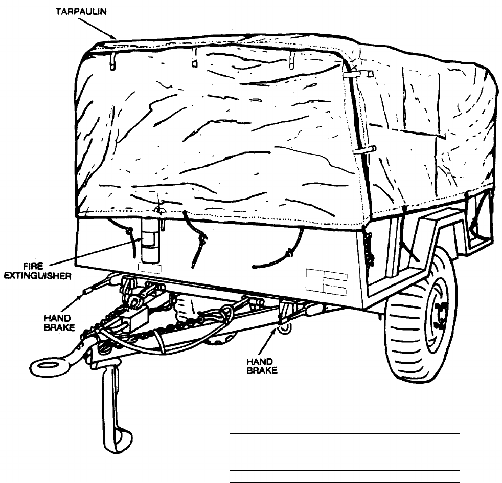
TM 5-6115-365-15
CAUTION
REMOVE TARPAULIN, BOWS AND RACKS BEFORE OPERATION. BE SURE
TAILGATE IS DOWN AND REMOVE ANYTHING IN THE TRAILER THAT MIGHT
OBSTRUCT THE FREE CIRCULATION OF AIR.
SHIPPING DIMENSIONS
LENGTH 147 INCHES
WIDTH 74 INCHES
HEIGHT 80 INCHES
WEIGHT 2850 POUNDS
Figure 17-1. PU-375B/G, left front, 3/4 view.
17-2.6 Change 10
TM 5-6115-365-15
C2
Section II. OPERATING INSTRUCTIONS
17-3. Setting-up Instructions
a. Leveling.
(1) Locate the trailer on as level a surface as
possible in order for the generator set to operate
efficiently.
(2) Set brakes and block wheels securely to
prevent any movement. Operate the handbrake at
weekly intervals to assure freedom of linkage.
(3) Pull leg support down and adjust length
for firm contact with ground.
WARNING
Wheels must be blocked, brakes set,
and leg support down in support
position before attempting to roll up
tarpaulin and before starting to
assemble or set-up the equipment for
operation.
b. Preparation for Starting.
(1) Roll up tarpaulin and remove bows and
racks. (Fig. 17-2)
(2) Open trailer tailgate and remove all loose
auxiliary items and anything else that might block the
free circulation of air through the trailer and around the
generator set.
CAUTION
It is of foremost importance that
there be free circulation of air around
the generator set at all times during
operation. Inadequate ventilation is a
major cause of damage to equipment.
c. Grounding.
WARNING
Never operate the generator set until
it has been properly grounded.
Electrical defects in the load lines or
equipment can cause death by
electrocution when contact is made
with an ungrounded system.
(1) The generator set must be grounded prior
to operation. The ground may be any of three methods,
depending on the location and terrain.
(a) A ground rod driven to a depth of 8
feet.
(b) An underground metallic water
piping system.
(c) A metal plate (9 sq. ft.) buried at a
depth of 4 feet.
(2) The ground lead must be No. 6 AWG
copper wire bolted or clamped to the rod, plate, or piping
system.
(3) Connect the other end of the ground lead
to the generator set ground terminal stud and connect
the generator to the ground terminal stud as shown in
figure 17-3.
WARNING
Never operate the generator set in an
enclosed area unless the exhaust
gases are piped to the outside.
Inhalation of exhaust fumes will
result in serious illness or death.
17-4. Starting
a. Perform setting-up and pre-starting procedures
(para 17-3).
b. Start the generator as instructed in
TM 5-6115-450-15.
17-5. Stopping
Stop the generator set as instructed in
TM 5-6115-450-15.
17-6. Operation
a. Operate the generator set as instructed in
TM 5-6115-450-15.
b. Perform the fuel transfer procedure as instructed
in figure 17-4.
17-3
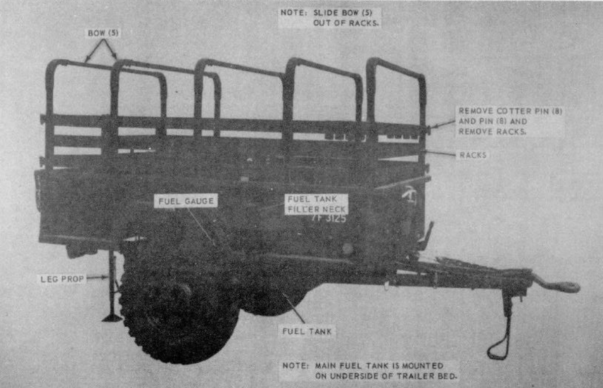
TM 5-6115-365-15
C2
ME 6115-365-15/17-2 C2
Figure 17-2. Bows and rocks, removal and installations.
17-4
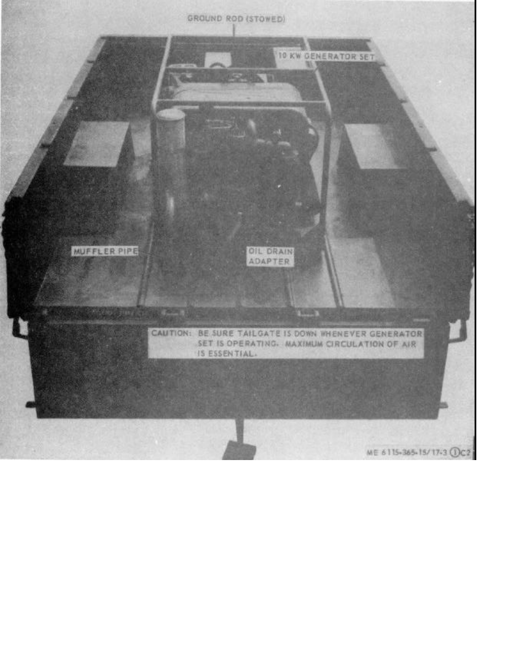
(Figure 17-3 Sheet 1 of 2)
(Figure 17-3 Sheet 2 of 2)
ME 6116-365-15/17-3 (1) C2
TM 5-6115-365-15
C2
Figure 17-3. PU-375B/G set up for operation (sheet 1 of 2).
17-5
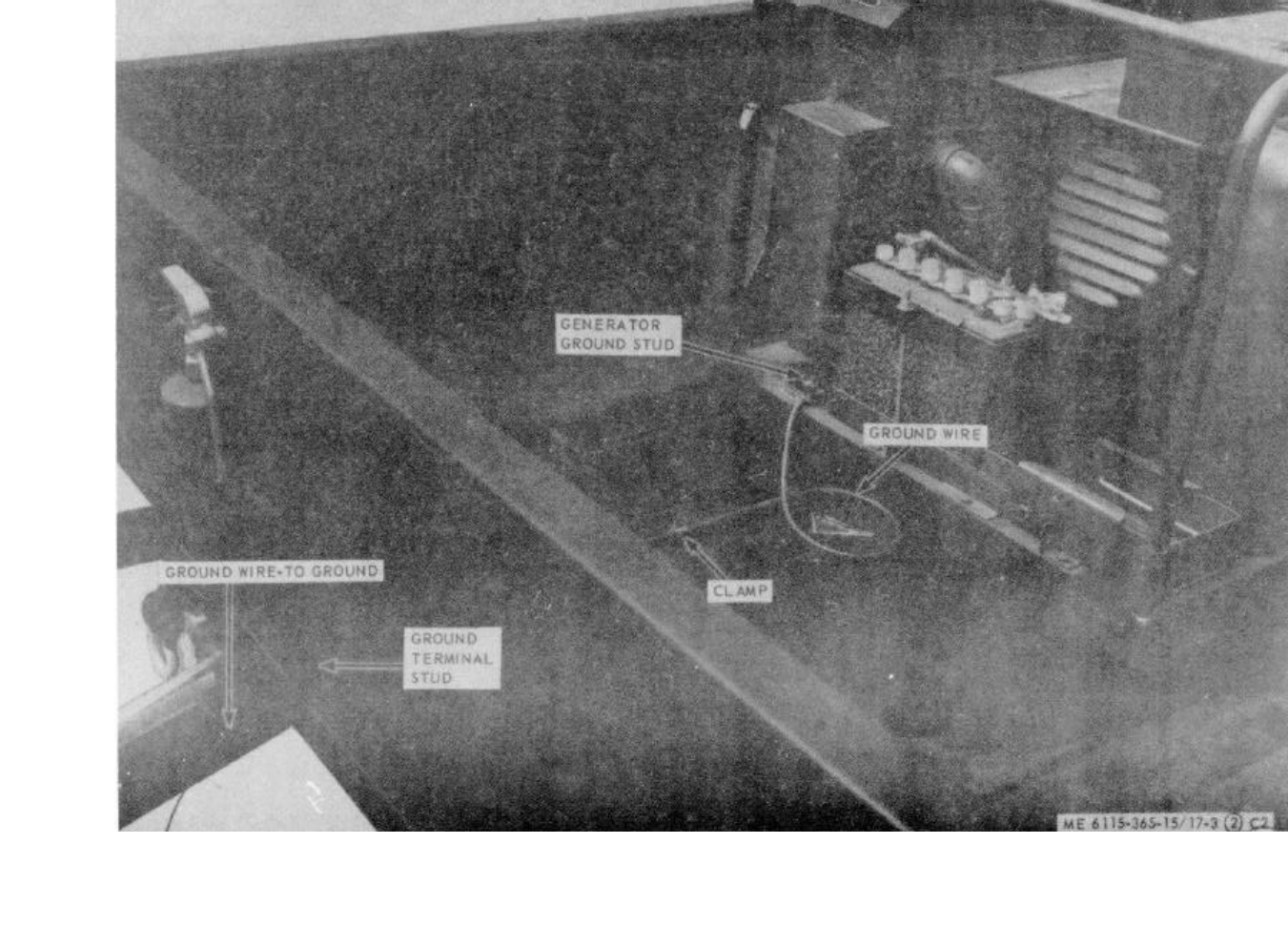
ME 6116-365-15/17-3 (2) C2
TM 5-6115-365-15
C2
Figure 17-3. PU-375B/G set up for operation (sheet 2 of 2).
17-6
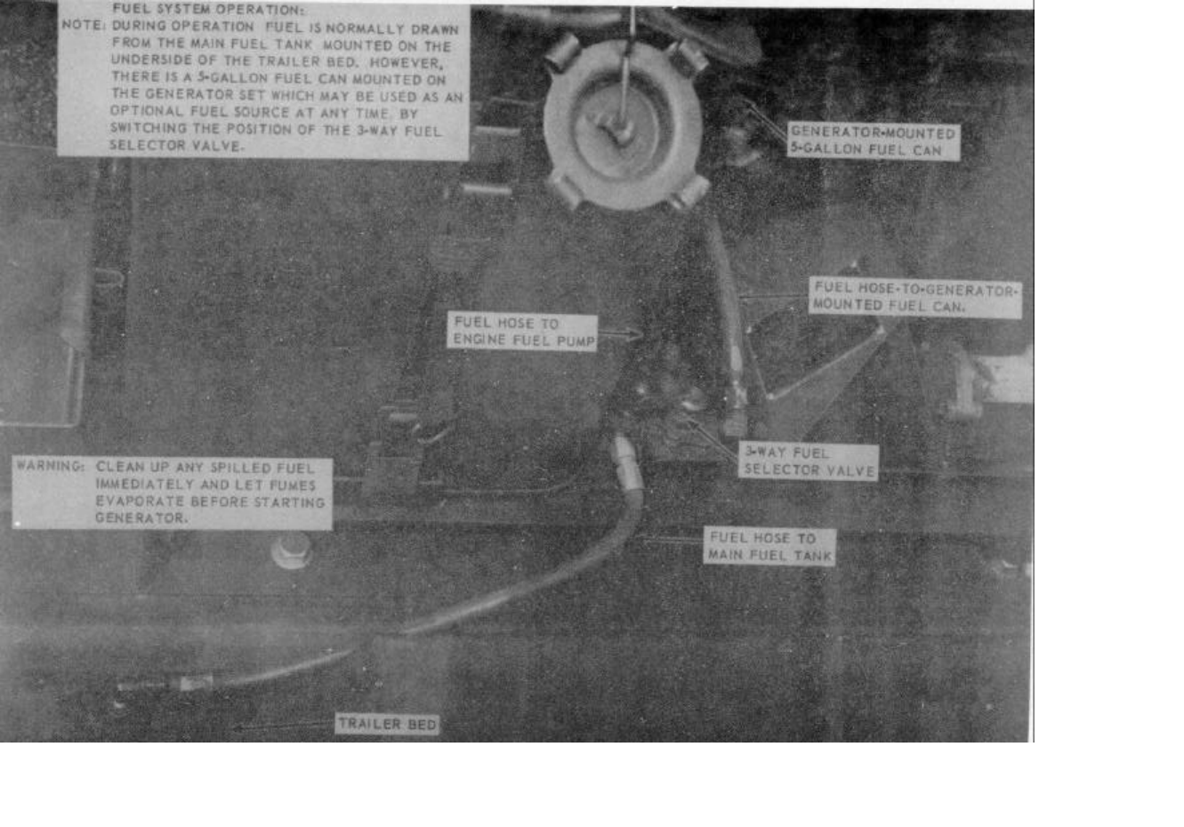
TM 5-6115-365-15
C2
ME 6116-365-15/17-4 C2
Figure 17-4. Fuel system connection and transfer procedure.
17-7
TM 5-6115-365-15
C2
Section III. OPERATOR'S MAINTENANCE INSTRUCTIONS
17-7. General
The PU-375B/G is equipped with an under-slung fuel
tank mounted under the trailer. The fuel filler neck
contains the fuel strainer which must be serviced by the
operator.
17-8. Fuel Tank Cap and Strainer Assembly
a. Removal. Remove fuel tank cap and pull out the
strainer assembly with the chain.
b. Cleaning and Inspection.
(1) Clean metal parts with approved cleaning
solvent and dry thoroughly.
(2) Inspect cap and strainer for damage and
defects. Inspect strainer screen for holes and gasket for
deterioration.
(3) Replace a defective fuel tank cap, gasket,
or strainer.
c. Installation. Place strainer assembly in filler
neck and install cap.
Section IV. ORGANIZATIONAL MAINTENANCE INSTRUCTIONS
17-9. Ground Wires and Terminal Stud
a. Removal. Refer to figure 17-3 and disconnect
ground wires, remove clamp and ground terminal stud.
b. Installation. Refer to figure 17-3 and install
ground terminal stud, connect ground wires, and install
clamp.
17-10. Tarpaulin, Roof Bows, Racks, and Leg Prop
a. Removal.
(1) Remove tarpaulin from unit.
(2) Remove the roof bows and racks as
shown in figure 17-2.
(3) Remove the hardware that secures the leg
prop to the rear underside of the trailer bed and remove
leg prop.
b. Cleaning and Inspection.
(1) Clean tarpaulin, bows, and racks with
water and detergent. Clean leg prop with approved
cleaning solvent. Dry thoroughly.
(2) Inspect tarpaulin for tears, holes, broken
or missing ropes and straps, and other defects. Inspect
bows, racks, and leg prop for cracks, bends, missing
pins, and other defects.
c. Installation.
(1) Mount the leg prop to the underside of the
trailer bed and secure with mounting hardware.
(2) Install the racks and roof bows as shown
in figure 17-2.
(3) Install tarpaulin and secure in desired
position.
17-11. Fuel Tank and Gage Assembly
a. General. The fuel tank on PU-375B/G is
mounted on the underside of the trailer bed, held in
place by 2 metal straps that are secured to cross braces
welded to the trailer. The fuel gage is mounted on top of
the tank.
b. Removal.
(1) Drain fuel tank.
(2) Disconnect either end of the ground wire
that connects to the fuel gage.
(3) Remove the 2 hose clamps and remove
the hose that connects the filler neck to the tank.
(4) Disconnect the breather line from the fuel
tank. (5) Remove the 2 nuts, 2 spacers, and
washers that secure the 2 retaining straps to the rear
tank brace. When straps are loose at rear, the tank will
drop down.
(6) Disconnect fuel line from top of tank and
remove tank.
(7) Remove 2 nuts, spacers, and washers
that secure retaining straps to the front brace and
remove the straps.
(8) Remove the 6 screws and washers that
secure the fuel gage to the tank and lift out gage.
c. Cleaning and Inspection.
(1) Clean all parts with approved cleaning
solvent and flush out any dirt and foreign particles from
inside the tank.
(2) Inspect tank for dents, rust, cracks, and
other damage. Inspect straps for defects
17-8
TM 5-6115-365-15
C2
and damaged or missing hardware. Inspect fuel gage
for damage and proper operation.
(3) Replace defective or missing parts as
necessary.
d. Installation.
(1) Install the fuel gage in the tank and secure
with 6 screws and washers.
(2) Secure the 2 retaining straps to the front
brace with the 2 nuts, spacers, and washers.
(3) Place the tank under the trailer and
connect the engine fuel line. Use a jack or other means
to lift the tank and hold it in position while the retaining
straps are being installed.
(4) Secure the 2 straps to the rear brace with
2 nuts, spacers, and washers.
(5) Connect the breather line to the fuel tank.
(6) Install the hose between the tank and filler
neck and secure with the 2 clamps.
(7) Connect the fuel gage ground wire.
(8) Fill fuel tank.
Section V. DIRECT AND GENERAL SUPPORT AND DEPOT
MAINTENANCE INSTRUCTIONS
17-12. Generator Set
a. Removal. Refer to figure 17-5 as a guide and
perform the following steps:
(1) Disconnect fuel lines.
(2) Disconnect electrical leads and load
cable. (3) Disconnect oil drain adapter.
(4) Remove 2 bolts and nuts that secure
muffler pipe to trailer.
(5) Remove the 4 bolts that secure the
generator set to the trailer and remove the generator set.
b. Installation. Use figure 17-5 as a guide and
perform the following steps:
(1) Secure the generator set to the trailer bed
with 4 bolts.
(2) Secure the muffler pipe to trailer bed with
2 bolts and 2 nuts.
(3) Connect the oil drain adapter.
(4) Connect the electrical leads and cable.
(5) Connect fuel lines.
17-13. Tarpaulin, Roof Bows, Racks, and Leg Prop
a. Removal. Remove tarpaulin, bows, racks, and
leg prop (para 17-10).
b. Repair.
(1) Patch or sew rips and tears in the
tarpaulin. Replace damaged or missing straps or ropes.
Replace a tarpaulin that is too badly damaged to be
repaired. (2) Weld minor cracks or breaks in the bows
or leg prop. Straighten bent bows where possible.
Replace defective or missing pins and hardware.
Replace bows, racks, or leg prop that are damaged
beyond repair.
c. Installation. Install racks, roof bows, leg prop,
and tarpaulin (para 17-10).
17-9
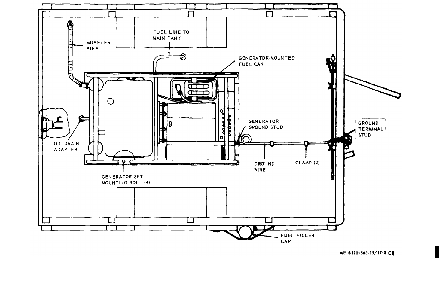
ME 6116-365-15/17-5 C2
TM 5-6115-365-15
C2
Figure 17-5. PU-3758/G overall component location diagram.
17-10
(1) (2) (3) (4) (5) (6) (7)
FEDERAL DESCRIPTION UNIT QTY 15-DAY ORGANIZATIONAL ILLUS-
SMR STOCK OF INC MAINTENANCE ALW RATION
CODE NUMBER USABLE MEAS IN (a) (b) (c) (d) (a) (b)
ON UNIT FIG ITEM
REF NUMBER & MFG CODE CODE 1-5 6-20 21-50 51-100 NO. NO.
TM 5-6115-365-15
PART I
REPAIR PARTS FOR ORGANIZATIONAL MAINTENANCE
00001 GROUP 03 - FUEL SYSTEM
00002 0306 - TANKS, LINES, FITTINGS
X2 OBRACKET, FUEL TANK ASSEMBLY EA 117-7 39
00003 13205E5080 (97403)
PO2910-911-0081 CAP, FUEL TANK: tactical vehicle fording EA 1****17-7 3
00004 MS35645-2 (96906)
X2 OCLAMP, HOSE: 1-13/16-2-3/4, range EA 217-8 7
00005 MS35842-13 (96906)
X2 OCLAMP, HOSE: 7/16-25/32, range EA 217-7 27
00006 MS35842-10 (96906)
X2 OCLAMP, LOOP, CUSHIONED: 3/4, nom, od EA 117-7 31
00007 MS21104D12 (96906)
X2 OCLAMP LOOP, CUSHIONED: 518 nom, od EA 117-8 2
00008 MS21104D10 (96906)
X2 OCOCK, DRAIN/HOSE BIB: 1/4-18 EA 117-9 13
00009 MS35783-2 (96906)
X2 OCOVER, FUEL TANK EA 117-9 9
00010 13216E7456 (97403)
X2 OELBOW: 90 deg, 37 deg, flare, 5/16-1/8 x 1/2-20 EA 117-9 8
00011 SAEJ514 (81343)
X2 OFILLER, FUEL TANK EA 117-7 4
00013 13205E5081 (97403)
PO2910-575-0998 FILTER EA 1****17-9 1
00014 1501596 (12204)
X2 OFITTING: 37 deg flare, 1/2-20 x 1/2-20 EA 117-6 6
00015 SAEJ514AFIG10C (81343)
X2 OGAGE, LIQUID, LEVEL EA 117-9 24
00016 13216E7459 (97403)
X2 O5330-01-165-6917 GASKET EA 117-9 21
00017 13216E7460 (97403)
X2 OGASKET, FUEL TANK EA 117-9 5
00018 13216E7453 (97403)
X2 OGASKET, FUEL TANK EA 117-9 10
00019 13216E7455 (97403)
X2 O2910-423-2730 GASKET, LEATHER EA 117-9 16
00020 7348979 (19702)
X2 OGROMMET: 1/16GR-1-5/8GR-D3/4H EA 117-7 33
00021 MS35489-120 (96906)
MOGROUND WIRE ASSEMBLY: 10 in., Ig EA 117-9 17
00022 13216E7462 (97403)
MANUFACTURE FROM:
X2 OTERMINAL, LUG: No. 16-14 AWG, No. 10 std EA 2
00023 MS20659-104 (96906)
POWIRE, ELECTRIC: No. 14 AWG FT SEE GRP 9501
00024 MILW76 (81349)
X2 OGUARD, FUEL GAGE EA 117-7 5
00025 13205E5083 (97403)
Change 8 17-11
(1) (2) (3) (4) (5) (6) (7)
FEDERAL DESCRIPTION UNIT QTY 15-DAY ORGANIZATIONAL ILLUS-
SMR STOCK OF INC MAINTENANCE ALW RATION
CODE NUMBER USABLE MEAS IN (a) (b) (c) (d) (a) (b)
ON UNIT FIG ITEM
REF NUMBER & MFG CODE CODE 1-5 6-20 21-50 51-100 NO. NO.
TM 5-6115-365-15
C2
PO4720-580-6659 HOSE ASSEMBLY: detachment fitting. 5/16, od, x 18 EA 1****17-6 9
00026 MS28741-5-0180 (96906)
PO4720-567-1681 HOSE ASSEMBLY: 5/16 tubing, od, x 48, Ig EA 1****17-8 1
00027 MS28741-5-0480 (96906)
POHOSE, FUEL: 2-id x 2-1/2, od, x 3, Ig EA 1SEE GRP 9501 17-8 6
00028 SAEJ30CLASS30R2TYPE2 (81343)
PO2910-881-3432 HOSE, RUBBER: 1/2 id, x 3/4 max, od, x 24 EA 1SEE GRP 9501 17-7 32
00029 MILH13444TYPEII (81349)
X2 OLOCKNUT: 37 deg flare, 1/2-20 EA 117-6 8
00030 SAEJ514FIG10A (81343)
X2 ONUT, INVERTED: 1/2 tube, od, 3/4-18 EA 117-9 18
00031 SAEJ512 (81343)
X2 ONUT, SELF-LOCKING HEXAGON: 1/4-20 EA 417-7 8
00032 MS51922-1 (96906)
X2 ONUT, SELF-LOCKING, HEXAGON: 1/4-20 EA 317-7 42
00033 MS51922-1 (96906)
X2 ONUT, SELF-LOCKING, HEXAGON: 1/4-20 EA 217-7 38
00034 MS51922-1 (96906)
X2 ONUT, SELF-LOCKING, HEXAGON: No. 10-32 EA 117-8 5
00035 MS21044N3 (96906)
X2 ONUT, SELF-LOCKING, HEXAGON: No. 10-32 EA 117-7 28
00036 MS21044N3 (96906)
X2 ONUT, SELF-LOCKING, HEXAGON: 3/8-16 EA 217-7 44
00037 MS51922-17 (96906)
X2 ONUT, SELF-LOCKING, HEXAGON: 5/16-18 EA 117-7 48
00038 MS51922-9 (96906)
X2 OMOUNT, GAGE EA 117-9 20
00039 13216E7458 (97403)
X2 OPLATE, CONNECTOR EA 117-9 2
00040 13216E7454-1 (97403)
X2 OPLATE, FUEL TANK EA 117-7 45
00041 13205E5133 (97403)
X2 OSCREW, CAP, HEXAGON HEAD: 5/16-18 x 7/8, Ig EA 117-7 46
00042 MS90725-33 (96906)
X2 OSCREW, CAP, HEXAGON HEAD: 1/4-20 x 5/8, Ig EA 417-7 6
00043 MS90725-5 (96906)
X2 OSCREW, CAP, HEXAGON HEAD: 1/4-20 x 1, Ig EA 217-7 36
00044 MS90725-8 (96906)
X2 OSCREW, CAP, HEXAGON HEAD. 114-20 x 7/8, g19 EA 317-7 40
00045 MS90725-7 (96906)
X2 OSCREW, MACHINE: No 10-24 x 3/4, Ig EA 10 17-9 7
00046 FFS92TYPEIIISTYLE9C (81348)
X2 OSCREW, MACHINE, PAN HEAD: No. 8-32 x 1/2, Ig EA 517-9 11
00047 MS35206-245 (96906)
X2 OSCREW, MACHINE, PAN HEAD: 10-32 x 5/8, Ig EA 617-9 22
00048 MS35207-264 (96906)
X2 OSCREW, MACHINE, PAN HEAD: 10-32 x 5/8, Ig EA 117-7 30
00049 MS35207-264 (96906)
X2 OSCREW, MACHINE, PAN HEAD: No. 10-32 x 5/8. Ig EA 117-8 3
00050 MS35207-264 (96906)
X2 OSTRAP. FUEL TANK EA 117-7 35
00051 13205E5082 (97403)
17-12

(1) (2) (3) (4) (5) (6) (7)
FEDERAL DESCRIPTION UNIT QTY 15-DAY ORGANIZATIONAL ILLUS-
SMR STOCK OF INC MAINTENANCE ALW RATION
CODE NUMBER USABLE MEAS IN (a) (b) (c) (d) (a) (b)
ON UNIT FIG ITEM
REF NUMBER & MFG CODE CODE 1-5 6-20 21-50 51-100 NO. NO.
TM 5-6115-365-15
C2
PO2930-420-8936 TANK ASSEMBLY, FUEL FILTER EA 1****17-7 58
00052 13216E7451-1 (97403)
PO2910-420-8930 TANK, FUEL EA 1* * a*17-9 14
00053 13216E7452 (97403)
POTUBING: 1/2 od, x .035 wall, x 3, lg EA 1SEE GRP 9501 17-9 19
00054 SAEJ526 (81343)
X2 OWASHER, FLAT: round, 3/8 screw size EA 217-7 43
00055 MS27183-15 (96906)
X2 OWASHER, FLAT: round, 1/4 BSC, size EA 317-7 41
00056 MS27183-10 (96906)
X2 OWASHER, FLAT: round, No. 10 BSC, size EA 117-7 29
00057 MS27183-8 (96906)
X2 OWASHER, FLAT: round, No. I0 BSC, size EA 117-8 4
00058 MS27183-8 (96906)
X2 OWASHER, FLAT: round, 1/4 BSC, size EA 217-7 37
00059 MS27183-10 (96906)
X2 OWASHER, FLAT: round, 1/4 BSC, size EA 417-7 7
00060 M527183-10 (96906)
X2 OWASHER, FLAT: round, 5/16 BSC, size EA 117-7 47
00061 MS27183-12 (96906)
X2 OWASHER, FLAT: round, .531 x 1, .062 x .095 EA 117-6 7
00062 MS27183-18 (96906)
X2 OWASHER, LOCK, SPRING, HELICAL: No. 8 nom EA 517-9 12
00063 MS35338-42 (96906)
X2 OWASHER, LOCK, SPRING, HELICAL: No. 10 nom, size EA 617-9 23
00064 MS35338-43 (96906)
X2 OWASHER, LOCK, SPRING, HELICAL: No. 12 nom, size EA 117-9 6
00065 USASB27-1 (80204)
00066 GROUP 04 - EXHAUST SYSTEM
00067 0401 - MUFFLER AND PIPE
X2 OCLAMP ASSEMBLY, TUBE EXHAUST EA 117-6 5
00068 13212E3592-14(97403)
X2 ONUT, SELF-LOCKING, HEXAGON: 1/4-20 EA 217-6 4
00069 MS51922-1 (96906)
X2 OSCREW, CAP, HEXAGON HEAD:1/4-20 x 1, lg EA 217-6 2
00070 MS90725-8 (96906)
PO6115-934-7878 TUBE EXHAUST EA 1****17-6 1
00071 13214E1389 (97403)
X2 OWASHER, FLAT: round, 1/4 BSC, size EA 417-6 3
00072 MS27183-10 (96906)
00073 GROUP 15 - FRAME, TOWING ATTACHMENTS, AND DRAWBARS
00074 1501 - FRAME ASSEMBLY
X2 O5340-999-6277 BRACKET ASSEMBLY EA 117-7 13
00075 13214E1214 (97403)
X2 OBRACKET, FUEL TANK EA 217-7 57
00076 13205E4953 (97403)
X2 OBRACKET, FUEL TANK ASSEMBLY EA 217-7 53
00077 13205E4952 (97403)
X2 O2590-932-7298 CLAMP, GROUND ROD EA 417-7 17
00078 13212E3617-1 (97403)
X2 OCLAMP, LOOP, CUSHIONED: 3/16, id EA 317-6 11
00079 MS21104D3 (96906)
17-13
(1) (2) (3) (4) (5) (6) (7)
FEDERAL DESCRIPTION UNIT QTY 15-DAY ORGANIZATIONAL ILLUS-
SMR STOCK OF INC MAINTENANCE ALW RATION
CODE NUMBER USABLE MEAS IN (a) (b) (c) (d) (a) (b)
ON UNIT FIG ITEM
REF NUMBER & MFG CODE CODE 1-5 6-20 21-50 51-100 NO. NO.
TM 5-6115-365-15
C2
X2 O5340-914-2578 CLIP SPRING EA 117-7 21
00080 13214E1213-1 (97403)
X2 ONUT, PLAIN, HEXAGON JAM:3/8-16 non-meg EA 217-7 65
00081 MS16203-39 (96906)
X2 ONUT, PLAIN, HEXAGON, MACHINE, SCREW: 10-24 EA 317-6 15
00082 MS35649-202 (96906)
X2 ONUT, PLAIN, HEXAGON: 3/8-16 non-mag EA 117-7 63
00083 MS16203-27 (96906)
X2 ONUT, PLAIN, WING BRASS: 3/8-16 EA 117-7 67
00084 MS35425-28 (96906)
X2 ONUT, SELF-LOCKING, HEXAGON EA 8 17-7 20
00085 MS51922-1 (96906)
X2 ONUT, SELF-LOCKING, HEXAGON:1/4-20 EA 117-7 23
00086 MS51922-1 (96906)
X2 ONUT, SELF-LOCKING, HEXAGON:1/4-20 EA 217-7 15
00087 MS51922-1 (96906)
X2 ONUT, SELF-LOCKING, HEXAGON:3/8-16 EA 3 17-7 62
00088 MS51922-17 (96906)
X2 ONUT, SELF-LOCKING, HEXAGON:3/8-16 EA 217-7 56
00089 MS51922-17 (96906)
X2 ONUT, SELF-LOCKING, HEXAGON:3/8-16 EA 217-7 2
00090o MS51922-17 (96906)
X2 ONUT, SELF-LOCKING, HEXAGON:3/8-16 EA 217-7 51
00091 MS51922-17 (96906)
X2 OSCREW, CAP, HEXAGON HEAD:1/4-20 x 3/4, lg EA 117-7 24
00092 MS90725-6 (96906)
X2 OSCREW, CAP, HEXAGON HEAD:1/4-20 x 3/4, LG EA 217-7 16
00093 MS90725-6 (96906)
X2 OSCREW, CAP, HEXAGON HEAD:3/8-16 x 1-3/4 EA 217-7 54
00094 MS90725-65 (96906)
X2 OSCREW, CAP, HEXAGON HEAD:3/8-16 x 1-1/4 EA 317-7 60
00095 MS90725-62 (96906)
X2 OSCREW, CAP, HEXAGON HEAD:3/8-16 x 2-1/4 EA 217-7 49
00096 MS90725-67 (96906)
X2 OSCREW, MACHINE, FLAT HEAD EA 817-7 18
00097 MS35190-290 (96906)
X2 OSCREW, MACHINE, PAN HEAD: 10-24 x 5/8, Ig EA 317-6 12
00098 MS35206-264 (96906)
X2 OSTUD, GROUNDING EA 117-7 68
00099 13214E1223 (97403)
X2 OSHIELD, FUEL TANK EA 117-7 59
00100 13205E4951 (97403)
X2 OWASHER, FLAT, ELECTRIC, BRASS: 3/8, size EA 417-7 66
00101 AN961-616 (88044)
X2 OWASHER, FLAT: round, 1/4 BSC, size EA 217-7 22
00102 MS27183-10 (96906)
X2 OWASHER, FLAT: round, 1/4 BSC, size EA 417-7 14
00103 MS27183-10 (96906)
X2 OWASHER, FLAT: round, 1/4 BSC, size EA 817-7 19
00104 MS27183-10 (96906)
X2 OWASHER, FLAT: round, No. 10 BSC, size EA 317-6 13
00105 MS27183-8 (96906)
17-14

(1) (2) (3) (4) (5) (6) (7)
FEDERAL DESCRIPTION UNIT QTY 15-DAY ORGANIZATIONAL ILLUS-
SMR STOCK OF INC MAINTENANCE ALW RATION
CODE NUMBER USABLE MEAS IN (a) (b) (c) (d) (a) (b)
ON UNIT FIG ITEM
REF NUMBER & MFG CODE CODE 1-5 6-20 21-50 51-100 NO. NO.
TM 5-6115-365-15
C2
X2 OWASHER, FLAT: round, 3/8 BSC, size EA 217-7 55
00106 MS27183-15 (96906)
X2 OWASHER, FLAT: round, 3/8 BSC, size EA 317-7 61
00107 MS27183-15 (96906)
X2 OWASHER, FLAT: round, 3/8 BSC, size EA 217-7 50
00108 MS27183-15 (96906)
X2 OWASHER, FLAT: round, 3/8 BSC, size EA 217-7 1
00109 MS27183-15 (96906)
X2 OWASHER, LOCK: No. 10 EA 317-6 14
00110 MS35338-43 (96906)
X2 OWASHER, LOCK, FLAT: external tooth, 3/8 EA 217-7 64
00111 S35335-91 (96906)
00112 1507 - LANDING GEAR, LEVELING JACKS
(MECHANICAL OR HYDRAULIC)
X2 O5310-087-4652 NUT, SELF-LOCKING, HEXAGON: 3/8-16 EA 317-6 25
00113 MS51922-17 (96906)
X2 OSCREW, CAP, HEXAGON HEAD: 3/8-16 x 1-1/4 EA 317-6 23
00114 MS90725-62 (96906)
P2 O2590-420-8929 TRAILER LEG PROP ASSEMBLY EA 1****17-6 22
00115 13214E1206 (97403)
X1 BRACKET, TRAILER LEG, PROP ASSEMBLY EA 117-6 22
00116 13214E1207 (97403)
X2 OFITTING, LUBRICATION: 1/8-27 NPT EA 117-6 22
00117 MS15006-1 (96906)
X1 LEG BASE EA 117-6 22
00118 13214E1212 (97403)
X1 LEG, UPPER EA 117-6 22
00119 13214E1208 (97403)
X1 NUT EA 117-6 22
00120 13214E1211 (97403)
X2 OPIN, COTTER: 1/8 dia, x 3/4, 19 EA 1 17-6 22
00121 MS24665-351 (96906)
X2 ORIVET, SOLID, HEAD EA 117-6 22
00122 MS20613-8P32 (96906)
X1 SCREW, TRAILER LEG EA 117-6 22
00123 13214E1210 (97403)
X1 SHAFT, TRAILER LEG EA 117-6 22
00124 13214E1209 (97403)
X2 OWASHER, FLAT: round, 3/8 BSC, size EA 617-6 24
00125 MS27183-15 (96906)
00126 GROUP 22 - BODY CHASSIS OR HULL,
AND ACCESSORY ITEMS
00127 2202 - ACCESSORY ITEMS
PC5975-878-3791 ROD, GROUND: 3 ft, section with attachments EA 2****17-7 25
00128 MILR11461 (81349)
PC5120-265-7462 HAMMER HAND, DOUBLE FACE: 8 lb EA 1****17-7 26
00129 GGGH86TYPEXCLASSI (81348)
00130 2210 - DATA PLATES
X2 OPLATE, IDENTIFICATION EA 117-6 10
00131 13205E4916-14(97403)
X2 OPLATE, IDENTIFICATION, GROUND TERMINAL EA 117-7 52
00132 13205E4918 (97403)
17-15
(1) (2) (3) (4) (5) (6) (7)
FEDERAL DESCRIPTION UNIT QTY 15-DAY ORGANIZATIONAL ILLUS-
SMR STOCK OF INC MAINTENANCE ALW RATION
CODE NUMBER USABLE MEAS IN (a) (b) (c) (d) (a) (b)
ON UNIT FIG ITEM
REF NUMBER & MFG CODE CODE 1-5 6-20 21-50 51-100 NO. NO.
TM 5-6115-365-15
C2
00133 GROUP 40 - ELECTRIC MOTORS AND GENERATORS
00134 4000 - GENERATOR ASSEMBLY
X2 ONUT, SELF-LOCKING, HEXAGON: 5/8-11 EA 417-6 17
00135 MS51922-49 (96906)
X2 OSCREW, CAP, HEXAGON HEAD: 5/8-11 x I-1/2 EA 417-6 20
00136 MS90725-162 (96906)
X2 OSPACER EA 417-6 18
00137 13214E1222-3 (97403)
X2 OWASHER, FLAT: round, 5/8 BSC, size EA 8 17-6 18
0137A MS27183-21 (96906)
00138 4019 - RADIO INTERFERENCE SUPPRESSION
MOWIRE, ELECTRIC: copper, 6 ft, No. 6 AWG, uninsulated FT 117-6 16
00139 QQW343TYPERBCLASSI (81348)
MANUFACTURE FROM:
PO6145-395-8799 WIRE, ELECTRIC: copper, No. 6 AWG, uninsulated FT SEE GRP 9501
00140 QQW343TYPERBCLASSI (81348)
00141 GROUP 76 - FIRE FIGHTING EQUIPMENT COMPONENTS
00142 7638 - PORTABLE FIRE FIGHTING EQUIPMENT
PC4210-555-8837 EXTINGUISHER, FIRE: 2-3/4, with bracket EA 1****17-7 9
00143 MILE52031 (81349)
X2 O5310-088-1251 NUT, SELF-LOCKING, HEXAGON:1/4-20 EA 417-7 11
00144 MS51922-1 (96906)
X2 O5305-068-0502 SCREW, CAP, HEXAGON HEAD:1/4-20 x 3/4, 19 EA 417-7 12
00145 MS90725-6 (96906)
X2 O5310-809-4058 WASHER, FLAT: round, 1/4 BSC, size EA 817-7 10
00146 MS27183-10 (96906)
00147 GROUP 95 - GENERAL USE STANDARDIZED PARTS
00148 9501 - HARDWARE SUPPLIES AND BULK MATERIAL, COMMON
PO2910-881-3432 HOSE, RUBBER: 1/2 in. id, 3/4 In. max od FT ****
00149 MILH13444TYPE2 (81349)
POHOSE: 2 in. id, 2-1/2 in. od FT ****
00150 SAEJ30CLASS30R2TYPE2 (81343)
POTUBING: 1/2 od, .035 wall FT ****
00151 SAEJ526 (81343)
POWIRE, ELECTRICAL: 14 AWG FT ****
00152 MILW76 (81349)
17-16

(1) (2) (3) (4) (5) (6) (7) (8) (9) (10)
DESCRIPTION 1-YR
DEPOT
QTY 30-DAY DS MAINT 30-DAY GS MAINT ALW
PER MAINT
ALW ILLUS-
TRATION
FEDERAL USABLE UNIT INC ALLOWANCE ALLOWANCE 100 PER (a) (b)
SMR
CODE STOCK
NUMBER
ON
ref NUMBER & MFR CODE CODE OF
MEAS IN
UNIT (a)
1-20 (b)
21-50 (c)
51-100 (a)
1-20 (b)
21-50 (c)
51-100
EQUIP
CNTGCY 100
EQUIP FIG.
NO. ITEM
NO.
TM 5-6115-365-15
C2
PART II
REPAIR PARTS FOR DS, GS,
AND DEPOT MAINTENANCE
00001 GROUP 03 - FUEL SYSTEM
00002 0306 - TANKS, LINES, FITTINGS
X2 OBRACKET, FUEL TANK ASSEMBLY EA 117-7 39
00003 13205E5080 (97403)
PO2910-911-0081 CAP, FUEL TANK: tactical vehicle
00004 fording EA 1* * 2* * 2 10 10 17-7 3
MS35645-2 (96906)
X2 OCLAMP, HOSE:1-13/16-2-3/4, range EA 217-8 7
00005 MS35842-13 (96906)
X2 OCLAMP, HOSE: 7/16-25/32, range EA 217-7 27
00006 MS35842-10 (96906)
X2 OCLAMP, LOOP, CUSHIONED: 3/4, nom, od EA 117-7 31
00007 MS21104012 (96906)
X2 OCLAMP, LOOP, CUSHIONED: 5/8, nom, od EA 117-8 2
00008 MS21104010 (96906)
X2 OCOCK, DRAIN/HOSE BIB: 1/4-18 EA 117-9 13
00009 MS35783-2 (96906)
X2 OCOVER, FUEL TANK EA 117-9 9
00010 13216E7456 (97403)
X2 OELBOW: 90 deg, 37 deg, flare,
00011 5/16-1/8 x 1/2-20 EA 17-9 8
SAEJ514 (81343)
X2 EXTENSION, TANK ASSEMBLY EA 117-9 15
00012 13216E7457 (97403) (WELDMENT)
X2 OFILLER, FUEL TANK EA 117-7 4
00013 13205E5081 (97403)
PO2910-575-0998 FILTER EA 1* * 2* * 2 10 10 17-9 1
00014 1501596 (12204)
X2 OFITTING: 37 deg flare, 1/2-20 x 1/2-20 EA 117-6 6
00015 SAEJ514AFIG10C (81343)
X2 OGAGE, LIQUID, LEVEL EA 117-9 24
00016 13216E7459 (97403)
X2 OGASKET EA 117-9 21
00017 13216E7460 (97403)
X2 OGASKET, FUEL TANK EA 17-9 5
00018 13216E7453 (97403)
X2 OGASKET, FUEL TANK EA 117-9 10
00019 13216E7455 (97403)
X2 O2910-423-2730 GASKET, LEATHER EA 117-9 16
00020 7348979 (19702)
X2OGROMMET: 1/16GR-1-5/8 GR-D3/4H EA 117-7 33
00021 MS35489-120 (96906)
MOGROUND WIRE ASSEMBLY: 10 in., 19g EA 117-9 17
00022 13216E7462 (97403)
MANUFACTURE FROM:
X2 OTERMINAL, LUG: No. 16-14 AWG, No.
00023 10 std EA 2
MS20659-104 (96906)
POWIRE, ELECTRIC: No. 14 AWG FT SEE GRP 9501
00024 MILW76 (81349)
17-17

(1) (2) (3) (4) (5) (6) (7) (8) (9) (10)
DESCRIPTION 1-YR
DEPOT
QTY 30-DAY DS MAINT 30-DAY GS MAINT ALW
PER MAINT
ALW ILLUS-
TRATION
FEDERAL USABLE UNIT INC ALLOWANCE ALLOWANCE 100 PER (a) (b)
SMR
CODE STOCK
NUMBER
ON
ref NUMBER & MFR CODE CODE OF
MEAS IN
UNIT (a)
1-20 (b)
21-50 (c)
51-100 (a)
1-20 (b)
21-50 (c)
51-100
EQUIP
CNTGCY 100
EQUIP FIG.
NO. ITEM
NO.
TM 5-6115-365-15
C2
X2 OGUARD, FUEL GAGE, EA 117-7 5
00025 13205E5083 (97403)
PO4720-580-6659 HOSE ASSEMBLY: detachment fitting
00026 5/16, od, x 18 EA 1******5 5 17-6 9
MS28741-5-0180 (96906)
PO4720-567-1681 HOSE ASSEMBLY: 5/16, tubing, od, x 48
00027 lg EA 1******5 5 17-8 1
MS28741-5-0480 (96906)
POHOSE, FUEL: 2-Id x 2-1/2, od, x 3,
00028 lg EA 1SEE GRP 9501 17-8 6
SAEJ30CLASS30 (81343)
PO2910-881-3432 HOSE, RUBBER:1/2 Id, x 3/4 max, od,
00029 x 24 EA 1SEE GRP 9501 17-7 32
MILH13444TYPE 11 (81349)
X2 OLOCKNUT: 37 deg flare, 1/2-20 EA 117-6 8
00030 SAEJ514FIG10A (81343)
X2 ONUT, INVERTED: 1/2 tube, od, 3/4-18 EA 117-9 18
00031 SAEJ512 (81343)
X2 ONUT, SELF-LOCKING, HEXAGON: 1/4-20 EA 417-7 8
00032 MS51922-1 (96906)
X2 ONUT, SELF-LOCKING, HEXAGON: 1/4-20 EA 317-7 42
00033 MS51922-1 (96906)
X2 ONUT, SELF-LOCKING, HEXAGON: 1/4-20 EA 217-7 38
00034 MS51922-1 (96906)
X2 ONUT, SELF-LOCKING, HEXAGON: No. 10-32 EA 117-8 5
00035 MS21044N3 (96906)
X2 ONUT, SELF-LOCKING, HEXAGON: No. 10-32 EA 117-7 28
00036 MS21044N3 (96906)
X2 ONUT, SELF-LOCKING, HEXAGON: 3/8-16 EA 217-7 44
00037 MS51922-17 (96906)
X2 ONUT, SELF-LOCKING, HEXAGON: 5/16-18 EA 117-7 48
00038 MS51922-9 (96906)
X2 OMOUNT, GAGE EA 117-9 20
00039 13216E7458 (97403)
X2 OPLATE, CONNECTOR EA 117-9 2
00040 13216E7454-1 (97403)
X2 OPLATE, FUEL TANK EA 117-7 45
00041 13205E5133 (97403)
X2OSCREW, CAP, HEXAGON HEAD: 5/16-18 x
00042 7/8, lg EA 117-7 46
MS90725-33 (96906)
X2 OSCREW, CAP, HEXAGON HEAD: 1/4-20 x
00043 5/8, lg EA 417-7 6
MS90725-5 (96906)
X2 OSCREW, CAP, HEXAGON HEAD: 1/4-20 x
00044 1, lg EA 217-7 36
MS90725-8 (96906)
X2 OSCREW, CAP, HEXAGON HEAD: 1/4-20 x
00045 7/8, lg EA 317-7 40
MS90725-7 (96906)
X2 OSCREW, MACHINE, PAN HEAD: No. 8-32 x
00046 1/2, Ig EA 517-9 11
MS35206-245 (96906)
X2 OSCREW, MACHINE: No. 10-24 x 3/4, Ig EA 10 17-9 7
00047 FFS92TYPEIIISTYLE9C (81343)
17-18

(1) (2) (3) (4) (5) (6) (7) (8) (9) (10)
DESCRIPTION 1-YR
DEPOT
QTY 30-DAY DS MAINT 30-DAY GS MAINT ALW
PER MAINT
ALW ILLUS-
TRATION
FEDERAL USABLE UNIT INC ALLOWANCE ALLOWANCE 100 PER (a) (b)
SMR
CODE STOCK
NUMBER
ON
ref NUMBER & MFR CODE CODE OF
MEAS IN
UNIT (a)
1-20 (b)
21-50 (c)
51-100 (a)
1-20 (b)
21-50 (c)
51-100
EQUIP
CNTGCY 100
EQUIP FIG.
NO. ITEM
NO.
TM 5-6115-365-15
C2
X2 OSCREW, MACHINE, PAN HEAD: 10-32 x 5/8,
00048 lg EA 617-9 22
MS35207-264 (96906)
X2 OSCREW, MACHINE, PAN HEAD: 10-32 x 5/8,
00049 lg EA 117-7 30
MS35207-264 (96906)
X2 OSCREW, MACHINE, PAN HEAD: No. 10-32 x
00050 5/8, lg EA 117-8 3
MS35207-264 (96906)
X2 OSTRAP, FUEL TANK EA 117-7 35
00051 13205E5082 (97403)
PO2910-420-8936 TANK ASSEMBLY, FUEL FILTER EA 1* * 2* * 2 10 10 17-7 58
00052 13216E7451-1 (97403)
PO2910-420-8930 TANK, FUEL EA 1* * 2* * 2 10 10 17-9 14
00053 13216E7452 (97403)
POTUBING: 1/2 od, x .035 wall, x 3, Ig EA 1SEE GRP 9501 17-9 19
00054 SAEJS26 (81343)
X2 OWASHER, FLAT: round, 3/8 screw size EA 217-7 43
00055 MS27183-15 (96906)
X2 OWASHER, FLAT: round, 1/4 BSC, size EA 317-7 41
00056 MS27183-10 (96906)
X2 OWASHER, FLAT: round, No. 10 BSC, size EA 117-7 29
00057 MS27183-8 (96906)
X2 OWASHER, FLAT: round, No. 10 BSC, size EA 117-8 4
00058 MS27183-8 (96906)
X2 OWASHER, FLAT: round, 1/4 BSC, size EA 217-7 37
D0059 MS27183-10 (96906)
X2 OWASHER, FLAT: round, 1/4 BSC, size EA 417-7 7
00060 MS27183-10 (96906)
X2 OWASHER, FLAT: round, 5/16 BSC, size EA 117-7 47
00061 MS27183-12 (96906)
X2 OWASHER, FLAT: round, .531 x 1, .062 x
00062 .095 EA 117-6 7
MS27183-18 (96906)
X2 OWASHER, LOCK, SPRING, HELICAL: No. 8
00063 nom EA 517-9 12
MS35338-42 (96906)
X2 OWASHER, LOCK, SPRING, HELICAL: No. 10
00064 nom, size EA 617-9 23
MS35338-43 (96906)
X2 OWASHER, LOCK, SPRING, HELICAL: No. 12
00065 nom, size EA 10 17-9 6
USASB27-1 (80204)
00066 GROUP O4 - EXHAUST SYSTEM
00067 0401 - MUFFLER AND PIPE
X2 OCLAMP ASSEMBLY, TUBE EXHAUST EA 117-6 5
00068 13212E3592-14 (97403)
X2 ONUT, SELF-LOCKING, HEXAGON: 1/4-20 EA 217-6 4
00069 MS51922-1 (96906)
X2 OSCREW, CAP, HEXAGON HEAD: 1/4-20 x 1,
00070 lg EA 217-6 2
MS90725-8 (96906)
PO6115-934-7878 TUBE EXHAUST EA 1* * 2* * 2 10 10 17-6 1
00071 13214E1389 (97403)
X2 OWASHER, FLAT: round, 1/4 BSC, size EA 417-6 3
00072 MS27183-10 (96906)
17-19

(1) (2) (3) (4) (5) (6) (7) (8) (9) (10)
DESCRIPTION 1-YR
DEPOT
QTY 30-DAY DS MAINT 30-DAY GS MAINT ALW
PER MAINT
ALW ILLUS-
TRATION
FEDERAL USABLE UNIT INC ALLOWANCE ALLOWANCE 100 PER (a) (b)
SMR
CODE STOCK
NUMBER
ON
ref NUMBER & MFR CODE CODE OF
MEAS IN
UNIT (a)
1-20 (b)
21-50 (c)
51-100 (a)
1-20 (b)
21-50 (c)
51-100
EQUIP
CNTGCY 100
EQUIP FIG.
NO. ITEM
NO.
TM 5-6115-365-15
C2
00073 GROUP 15 - FRAME, TOWING
ATTACHMENTS, AND DRAWBARS
00074 1501 - FRAME ASSEMBLY
X2 O5340-999-6277 BRACKET ASSEMBLY EA 117-7 13
00075 13214E1214 (97403)
X2 OBRACKET, FUEL TANK EA 217-7 57
00076 13205E4953 (97403)
X2 OBRACKET, FUEL TANK ASSEMBLY EA 217-7 53
00077 13205E4952 (97403)
X2 O2590-932-7298 CLAMP, GROUND ROD EA 417-7 17
00078 13212E3617-1 (97403)
X2 OCLAMP, LOOP, CUSHIONED: 3/16, id EA 317-6 11
00079 MS21104D3 (96906)
X2 O5340-914-2578CLIP SPRING EA 17-7 21
00080 13214E1213-1 (97403)
X2 ONUT, PLAIN, HEXAGON JAM: 3/8-16
00081 non-mag EA 217-7 65
MS16203-39 (96906)
X2 ONUT, PLAIN, HEXAGON, MACHINE, SCREW:
00082 10-24 EA 317-6 15
MS35649-202 (96906)
X2 ONUT, PLAIN, HEXAGON: 3/8-16 non-mag EA 117-9 63
00083 MS16203-27 (96906)
X2 ONUT, PLAIN, WING BRASS: 3/8-16 EA 117-7 67
00084 MS35425-28 (96906)
X2 ONUT, SELF-LOCKING, HEXAGON EA 817-7 20
00085 MS51922-1 (96906)
X2 ONUT, SELF-LOCKING, HEXAGON: 1/4-20 EA 117-7 23
00086 MS51922- 1 (96906)
X2 ONUT, SELF-LOCKING, HEXAGON: 1/4-20 EA 217-7 15
00087 MS51922-1 (96906)
X2 ONUT, SELF-LOCKING, HEXAGON: 3/8-16 EA 317-7 62
00088 MS51922-17 (96906)
X2 ONUT, SELF-LOCKING, HEXAGON: 3/8-16 EA 217-7 56
00089 MS51922-17 (96906)
X2 ONUT, SELF-LOCKING, HEXAGON: 3/8-16 EA 217-7 2
00090 MS51922-17 (96906)
X2 ONUT, SELF-LOCKING, HEXAGON: 3/8-16 EA 217-7 51
00091 MS51922-17 (96906)
X2 OSCREW, CAP, HEXAGON HEAD: 1/4-20 x
00092 3/4, lg EA 117-7 24
MS90725-6 (96906)
X2 OSCREW, CAP, HEXAGON HEAD: 1/4-20 x
00093 3/4, Ig EA 217-7 16
MS90725-6 (96906)
X2 OSCREW, CAP, HEXAGON HEAD: 3/8-lb x
00094 1-3/4 EA 217-7 54
MS90725-65 (96906)
X2 OSCREW, CAP, HEXAGON HEAD: 3/8-16 x
00095 1-1/4 EA 317-7 60
MS90725-62 (9b906)
X2 OSCREW, CAP, HEXAGON HEAD: 3/8-16 x
00096 2-1/4 EA 217-7 49
MS90725-67 (96906)
17-20
(1) (2) (3) (4) (5) (6) (7) (8) (9) (10)
DESCRIPTION 1-YR
DEPOT
QTY 30-DAY DS MAINT 30-DAY GS MAINT ALW
PER MAINT
ALW ILLUS-
TRATION
FEDERAL USABLE UNIT INC ALLOWANCE ALLOWANCE 100 PER (a) (b)
SMR
CODE STOCK
NUMBER
ON
ref NUMBER & MFR CODE CODE OF
MEAS IN
UNIT (a)
1-20 (b)
21-50 (c)
51-100 (a)
1-20 (b)
21-50 (c)
51-100
EQUIP
CNTGCY 100
EQUIP FIG.
NO. ITEM
NO.
TM 5-6115-365-15
C2
X2 OSCREW, MACHINE, FLAT HEAD EA 817-7 18
00097 MS35190-290 (96906)
X2 OSCREW, MACHINE, PAN HEAD: 10-24 X 5/8,
00098 lgEA 317-6 12
MS35206-264 (96906)
X2 OSTUD, GROUNDING EA 117-7 68
00099 13214E1223 (97403)
X2 OSHIELD, FUEL TANK EA 117-7 59
00100 13205E4951 (97403)
X2 OWASHER, FLAT, ELECTRIC, BRASS: 3/8, size EA 417-7 66
00101 AN961-616 (88044)
X2 OWASHER, FLAT: round, 1/4 BSC, size EA 217-7 22
00102 MS27183-10 (96906)
X2 OWASHER, FLAT: round, 1/4 BSC, size EA 417-7 14
00103 MS27183-10 (96906)
X2 OWASHER, FLAT: round, 1/4 BSC, size EA 817-7 19
00104 MS27183-10 (96906)
X2 OWASHER, FLAT: round, No. 10 BSC, size EA 317-6 13
00105 MS27183-8 (96906)
X2 OWASHER, FLAT: round, 3/8 BSC, size EA 217-7 55
00106 MS27183-15 (96906)
X2 OWASHER, FLAT: round, 3/8 BSC, size EA 317-7 61
00107 MS27183-15 (96906)
X2 OWASHER, FLAT: round, 3/8 BSC, size EA 217-7 50
00108 MS27183-15 (96906)
X2 OWASHER, FLAT: round, 3/8 BSC, size EA 217-7 1
00109 MS27183-15 (96906)
X2 OWASHER, LOCK: No. 10 EA 317-6 14
00110 MS35338-43 (96906)
X2 OWASHER, LOCK, FLAT: external tooth, 3/8 EA 217-7 64
00111 M3535335-91 (96906)
00112 1507 - LANDING GEAR,
LEVELING JACKS
(MECHANICAL OR HYDRAULIC)
X2 O5310-087-4652 NUT, SELF-LOCKING, HEXAGON: 3/8-16 EA 317-6 25
00113 MS51922-17 (96906)
X2 OSCREW, CAP, HEXAGON HEAD: 3/8-16 x
00114 1-1/4 EA 317-6 23
MS90725-62 (96906)
P2 O2590-420-8929 TRAILER LEG PROP ASSEMBLY EA 1* * 2* * 2 10 10 17-6 22
00115 13214E1206 (97403)
X1 BRACKET TRAILER LEG, PROP ASSEMBLY EA 117-6 22
00116 13214E1207 (97403)
X2 OFITTING, LUBRICATION: 1/8-27 NPT EA 117-6 22
00117 MS15006-1 (96906)
X1 LEG BASE EA 117-6 22
00118 13214E1212 (97403)
X1 LEG, UPPER EA 117-6 22
00119 13214E1208 (97403)
X1 NUT EA 117-6 22
00120 13214E1211 (97403)
X2 OPIN, COTTER: 1/8 dia, x 3/4 19 EA 117-6 22
00121 MS24665-351 (96906)
17-21

(1) (2) (3) (4) (5) (6) (7) (8) (9) (10)
DESCRIPTION 1-YR
DEPOT
QTY 30-DAY DS MAINT 30-DAY GS MAINT ALW
PER MAINT
ALW ILLUS-
TRATION
FEDERAL USABLE UNIT INC ALLOWANCE ALLOWANCE 100 PER (a) (b)
SMR
CODE STOCK
NUMBER
ON
ref NUMBER & MFR CODE CODE OF
MEAS IN
UNIT (a)
1-20 (b)
21-50 (c)
51-100 (a)
1-20 (b)
21-50 (c)
51-100
EQUIP
CNTGCY 100
EQUIP FIG.
NO. ITEM
NO.
TM 5-6115-365-15
C2
X2 ORIVET, SOLID, HEAD EA 117-6 22
00122 M20613-8P32 (96906)
X1 SCREW, TRAILER LEG EA 117-6 22
00123 13214E1210 (97403)
X1 SHAFT, TRAILER LED EA 117-6 22
00124 13214E1209 (97403)
X2 OWASHER, FLAT: round, 3/8 BSC, size EA 617-6 24
00125 MS27183-15 (96906)
00126 GROUP 18 - BODY, CAB,
HOOD AND HULL
0126A 1810 - CARGO BODY
X2 FR2330-898-6779 TRAILER EA 117-6 21
00127 132143489 (97403)
00128 GROUP 22 - BODY CHASSIS OR
HULL, AND ACCESSORY ITEMS
00129 2202 - ACCESSORY ITEMS
PC5975-878-3791 ROD, GROUND: 3 ft, section with attachments EA 2* * 2* * 2 10 10 17-7 25
00130 MILR11461 (81349)
PC5120-265-7462 HAMMER, HAND, DOUBLE FACE: 8 lb EA 1* * 2* * 2 10 10 17-7 26
00131 GGGH86TYPEXCLASS1 (81348)
00132 2210 - DATA PLATES
X2 OPLATE, IDENTIFICATION: EA 117-6 10
00133 13205E4916-14 (97403)
X2 OPLATE, IDENTIFICATION, GROUND TERMINAL EA 117-7 52
00134 13205E4918 (97403)
00135 GROUP 40 - ELECTRIC MOTORS AND OPERATORS
00136 4000 - GENERATOR ASSEMBLY
X2 FR 6115-937-1793 GENERATOR SET: 10KW-400HZ, skid mtd EA 117-6 26
00137 MILG52280 (81349)
X2 ONUT, SELF-LOCKING, HEXAGON: 5/8-11 EA 417-6 17
00138 MS51922-49 (96906)
X2 OSCREW, CAP, HEXAGON HEAD: 5/8-11 x 1-1/2 EA 417-6 20
00139 MS90725-162 (96906)
X2 OSPACER EA 417-6 18
00140 132141l222-3 (97403)
X2 OWASHER, FLAT: round, 5/8 BSC, size EA 817-6 19
00141 MS27183-21 (96906)
00142 4019 - RADIO INTERFERENCE
SUPPRESSION
MOWIRE, ELECTRIC: copper, 6 ft, No. 6 AWG,
00143 uninsulated FT 117-6 16
QQW343TTPERBCLASS1 (81348)
MANUFACTURE FROM:
PO6145-395-8799 WIRE, ELECTRIC: copper, No. 6 AWG,
00144 uninsulated FT SEE GRP 9501
QQW343TYPERSCLASS1 (81348)
17-22
(1) (2) (3) (4) (5) (6) (7) (8) (9) (10)
DESCRIPTION 1-YR
DEPOT
QTY 30-DAY DS MAINT 30-DAY GS MAINT ALW
PER MAINT
ALW ILLUS-
TRATION
FEDERAL USABLE UNIT INC ALLOWANCE ALLOWANCE 100 PER (a) (b)
SMR
CODE STOCK
NUMBER
ON
ref NUMBER & MFR CODE CODE OF
MEAS IN
UNIT (a)
1-20 (b)
21-50 (c)
51-100 (a)
1-20 (b)
21-50 (c)
51-100
EQUIP
CNTGCY 100
EQUIP FIG.
NO. ITEM
NO.
TM 5-6115-365-15
C2
00145 GROUP 76 - FIRE FIGHTING
EQUIPMENT COMPONENTS
00146 7638 - PORTABLE FIRE
PC4210-555-8837 EXTINGUISHER, FIRE: 2-3/4, with bracket EA 1* * 2* * 2 10 10 17-7 9
00147 MILE52031 (81349)
X2 O5310-088-1251 NUT, SELF-LOCKING, HEXAGON: 1/4-20 EA 417-7 11
00148 6N51922-1 (96906)
X2 O5305-068-0502 SCREW, CAP, HEXAGON HEAD: 1/4-20 x 3/4, lg EA 417-7 12
00149 MS90725-6 (96906)
X2 O5310-809-4058 WASHER, FIAT: round, 1/4 BSC, size EA 817-7 10
00150 MS27183-10 (96906)
00151 GROUP 95 - GENERAL USE
STANDARDIZED PARTS
00152 9501 - HARDWARE SUPPLIES
AND BULK MATERIAL, COMMON
PO2910-881-3432 HOSE, RUBBER: 1/2 in. id, 3/4 in. max od FT *******5 5
00153 MILH13444TYPE2 (81349)
POHOSE: 2 in. id, 2-1/2 in. od FT *******10 10
00154 SAEJ30CLASS30R2TYPE2 (81343)
POTUBING: 1/2 od, .035 wall FT *******10 10
00155 SAEJ526 (81343)
POWIRE, ELECTRICAL: 14 AWG FT ******** *
00156 MILW76 (81349)
17-23
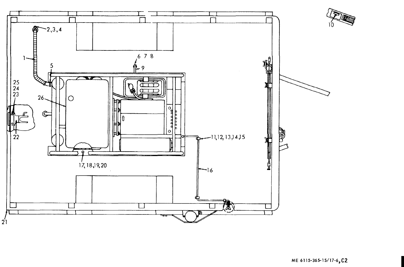
TM 5-6115-365-15
C2
Figure 17-6. Power unit components.
17-24
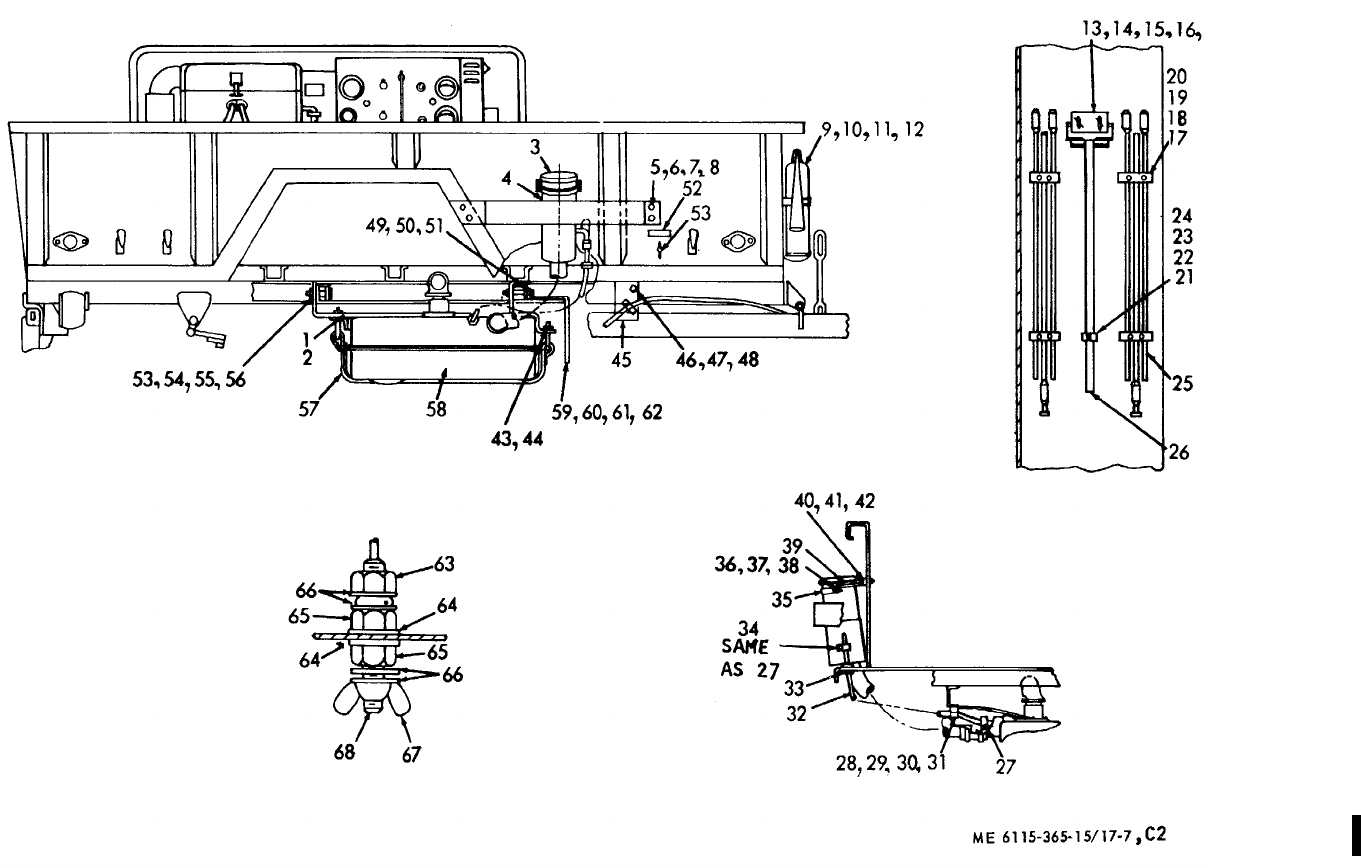
TM 5-6115-365-15
C2
Figure 17-7. Detail components.
17-25
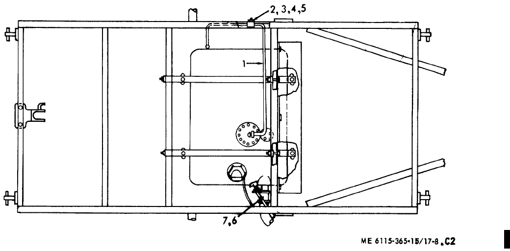
TM 5-6115-365-15
C2
Figure 17-8. Fuel tank mounting components.
17-26
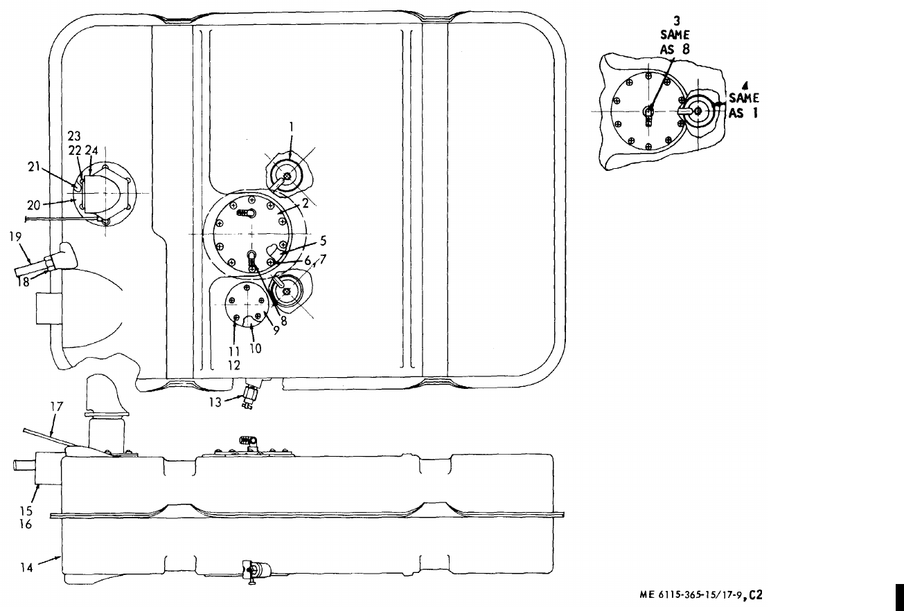
TM 5-6115-365-15
C2
Figure 17-9. Fuel tank components. 17-27

TM 5-6115-365-15
CHAPTER 18
GENERATOR SET PU-628/G
Section I. DESCRIPTION AND DATA
18-1. Description
a. General. The PU-628/G is a self-contained,
mobile, general purpose power supply (Fig. 18-1). The
set is comprised of two 3 KW Model SF 3.0 MD Military
Standard generator sets, mounted on an M101 trailer
and includes the components listed in table 18-1. The
generators are powered by directly coupled, 4-cylinder,
6-hp, Military Standard engines. A power transfer switch
is provided for connecting the generator outputs to a
common load.
b. Engines. For description and maintenance
information pertaining to the engines, refer to
TM 5-2805-203-14.
c. Generators. For description and operation and
maintenance information not covered in this chapter,
refer to TM 5-6115-271-14.
d. Trailer. For description and trailer maintenance
information, refer to TM 9-2330-202-14.
18-2. Tabulated Data
Table 18-1 lists the components for PU-628/G.
Table 18-1. PU-628/G Components
Fsn Qty Nomenclature
2330-738-9509 1Trailer: M101
2590-318-6691 1Leg prop assembly, trailer
6115-01-143-3311 2Generator: 3KW, 60 cycle,
Model SF-3.0 MD
4210-555-8837 1Fire extinguisher
5975-878-3791 2Ground rod (w/attachments)
5120-265-7462 1Sledge hammer
FSN not
assigned 1Fuel tank assembly
Change 8 18-1
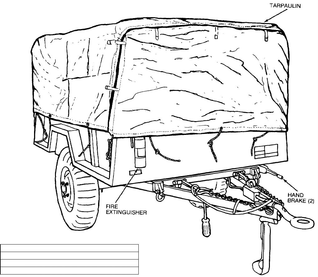
TM 5-6115-365-15
CAUTION
REMOVE TARPAULIN, BOWS AND RACKS BEFORE OPERATION. BE SURE
TAILGATE IS DOWN AND REMOVE ANYTHING IN THE TRAILER THAT MIGHT
OBSTRUCT THE FREE CIRCULATION OF AIR.
SHIPPING DIMENSIONS
LENGTH 147 INCHES
WIDTH 74 INCHES
HEIGHT 80 INCHES
WEIGHT 2850 POUNDS
Figure 18-1. PU-628/G, right front, 3/4 view.
18-2
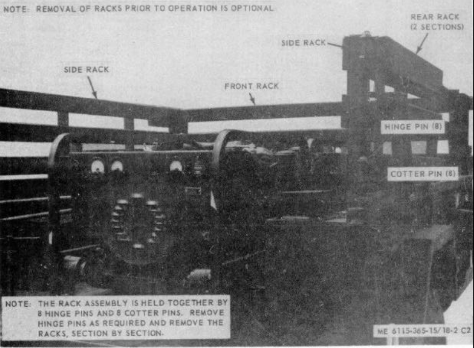
TM 5-6115-365-15
C2
Section II. OPERATING INSTRUCTIONS
18-3. Setting-up Instructions
a. Leveling.
(1) Locate the trailer on as level a surface as
possible in order for the generator sets to operate
efficiently.(2) Set brakes and block wheels securely to
prevent any movement. Operate the handbrake at
weekly intervals to assure freedom of linkage.
(3) Pull leg support down and adjust length
for firm contact with ground.
WARNING
Wheels must be blocked, brakes set,
and leg support down in support
position before attempting to roll up
tarpaulin and before starting to
assemble or set-up equipment for
operation.
b. Preparation for Starting.
(1) Roll up tarpaulin and remove the bows
and racks (Fig. 18-2).
(2) Open trailer tailgate and remove all loose
auxiliary items and anything else that might block the
free circulation of air through the trailer and around
generator sets.
CAUTION
It is of foremost importance that
there be free circulation of air around
the generator set at all times during
operation. inadequate ventilation is a
major cause of damage to equipment.
Figure 18-2. Racks, removal and installation.
18-3
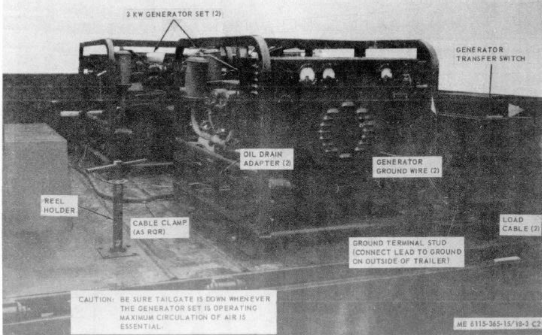
TM 5-6115-365-15
C2
Figure 18-3. PU-628/C set up for operation.
18-4
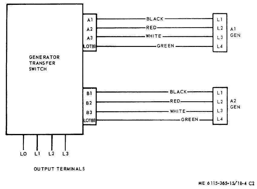
TM 5-6115-365-15
C2
c. Grounding.
WARNING
Never operate the generator set until
it has been properly grounded.
Electrical defects in the load lines or
equipment can cause death by
electrocution when contact is made
with an underground system.
(1) The generator set must be grounded prior
to operation. The ground may be any of three methods,
depending on the location and terrain:
(a) A ground rod driven to a depth of 8
feet.
(b) An underground metallic water
piping system.
(c) A metal plate (9 sq. ft.) buried at a
depth of 4 feet.
(2) The ground lead must be No. 6 AWG
copper wire, bolted or clamped to the rod, plate, or
piping system.
(3) Connect the other end of the ground lead
to the generator set ground terminal stud and connect
the generator to the ground terminal stud as shown in
figure 18-3.
WARNING
Never operate the generator set in an
enclosed area unless the exhaust
gases are piped to the outside.
Inhalation of exhaust fumes will
result in serious illness or death.
(4) Be sure the transfer switch load cables
are connected to the generator sets as illustrated in
figure 18-4.
Figure 18-4. Interconnection diagram, transfer switch-to-generators.
18-5
TM 5-6115-365-15
C2
18-4. Starting
a. Perform the setting-up and pre-starting
procedures described in paragraph 18-3.
b. Start the generator set as instructed in
TM 5-6115-271-15.
18-5. Stopping
Stop the generator set as instructed in
TM 5-6115-271-15.
18-6. Operation
Operate the generator set as instructed in
TM 5-6115-271-15.
Section III. OPERATOR'S MAINTENANCE INSTRUCTIONS
18-7. Transfer Switch Indicating Lamps
a. Removal. Remove the indicating lamps as
illustrated in figure 18-5.
b. Installation. Install the indicating lamps as
illustrated in figure 18-5.
18-8. Fuel Tank Cap and Strainer Assembly
a. Removal. Remove fuel tank cap and pull out the
strainer assembly with the chain.
b. Cleaning and Inspection.
(1) Clean metal parts with approved cleaning
solvent and dry thoroughly.
(2) Inspect cap and strainer for damage and
defects. Inspect strainer screen for holes and gasket for
deterioration.
(3) Replace a defective fuel tank cap, gasket,
or strainer.
c. Installation. Place strainer assembly in filler
neck and install cap.
18-6
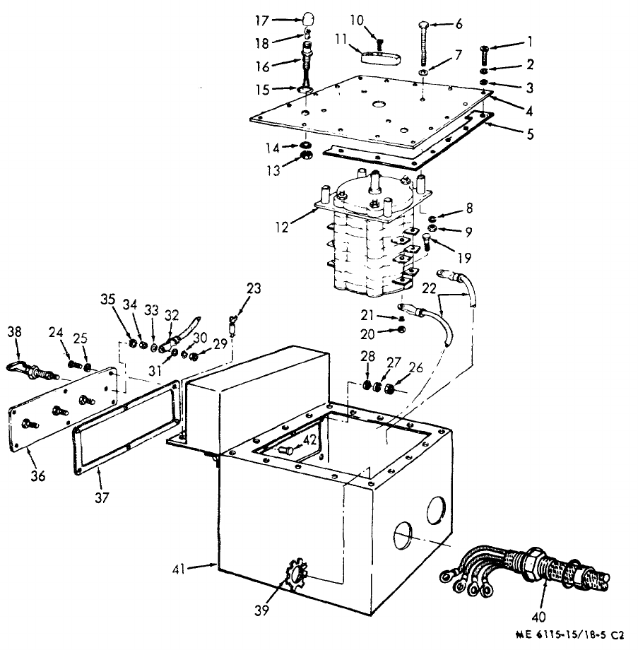
TM 5-6115-365-15
C2
1Screw 12 Transfer switch 23 Fastener 34 Hex nut
2Lockwasher 13 Hex nut 24 Screw 35 Lockwasher
3Flat washer 14 Lockwasher 25 Flat washer 36 Terminal board
4Cover 15 Preformed packing 26 Hex nut 37 Gasket
5Gasket 16 Light and wire assy 27 Lockwasher 38 Terminal lug
6Screw 17 Lens 28 Flat washer 39 Locknut
7Flat washer 18 Lamp 29 Hex nut 40 Stuffing tube assy
8Lockwasher 19 Screw 30 Lockwasher 41 Transfer switch box
9Hex nut 20 Hex nut 31 Flat washer 42 Rivet
10 Screw 21 Lockwasher 32 Electrical lead
11 Knob 22 Electrical lead 33 Flat washer
Figure 18-5. Transfer switch, removal, disassembly, reassembly, and installation.
18-7
TM 5-6115-365-15
C2
Section IV. ORGANIZATIONAL MAINTENANCE INSTRUCTIONS
18-9. Ground Wires and Terminal Stud
a. Removal. Refer to figure 18-3 and disconnect
ground wires, remove clamps and ground terminal stud.
b. Installation. Refer to figure 18-3 and install the
ground terminal stud, connect ground wires, and install
clamps.
18-10. Tarpaulin, Roof Bows, Racks, and Leg Prop
a. Removal.
(1) Remove tarpaulin from unit.
(2) Remove the roof bows and racks as
shown in figure 18-2.
(3) Remove the hardware that secures the leg
prop to the underside of the trailer bed and remove the
leg prop.
b. Cleaning and Inspection.
(1) Clean tarpaulin, bows, and racks with
water and detergent. Clean leg prop with approved
cleaning solvent and dry thoroughly.
(2) Inspect tarpaulin for tears, holes, broken
or missing ropes and straps, and other defects. Inspect
bows, racks, and leg prop for cracks, bends, missing
pins, and other defects.
c. Installation.
(1) Mount the leg prop to the underside of the
trailer bed and secure with mounting hardware.
(2) Install the racks and roof bows as shown
in figure 18-2.
(3) Install tarpaulin and secure in desired
position.
18-11. Fuel Tank and Gage Assembly
a. General. The fuel tank on PU-628/G is mounted
on the underside of the trailer bed, held in place by 2
metal straps that are secured to cross braces welded to
the trailer. The fuel gage is mounted on top of the tank.
b. Removal.
(1) Drain fuel tank.
(2) Disconnect either end of the ground wire
that connects to the fuel gage.
(3) Remove the 2 hose clamps and remove
the hose that connects the filler neck to the tank.
(4) Disconnect the breather line from the fuel
tank. (5) Remove the 2 nuts, 2 spacers, and
washers that secure the 2 retaining straps to the rear
tank brace. When straps are loose at rear, the tank will
drop down.
(6) Disconnect fuel line from top of tank and
remove tank.
(7) Remove 2 nuts, spacers, and washers
that secure retaining straps to the front brace and
remove the straps.
(8) Remove the 6 screws and washers that
secure the fuel gage to the tank and lift out gage.
c. Cleaning and Inspection.
(1) Clean all parts with approved cleaning
solvent and flush out any dirt and foreign particles from
inside the tank.
(2) Inspect tank for dents, rust, cracks, and
other damage. Inspect straps for defects and damaged
or missing hardware. Inspect fuel gage for damage and
proper operation.
(3) Replace defective or missing parts as
necessary.
d. Installation.
(1) Install the fuel gage in the tank and secure
with 6 screws and washers.
(2) Secure the 2 retaining straps to the front
brace with the 2 nuts, spacers, and washers.
(3) Place the tank under the trailer and
connect the engine fuel line. Use a jack or other means
to lift the tank and hold it in position while the retaining
straps are being installed.
(4) Secure the 2 straps to the rear brace with
2 nuts, spacers, and washers.
(5) Connect the breather line to the fuel tank.
(6) Install the hose between the tank and filler
neck and secure with 2 clamps.
(7) Connect the fuel gage ground wire.
(8) Fill fuel tank.
18-8
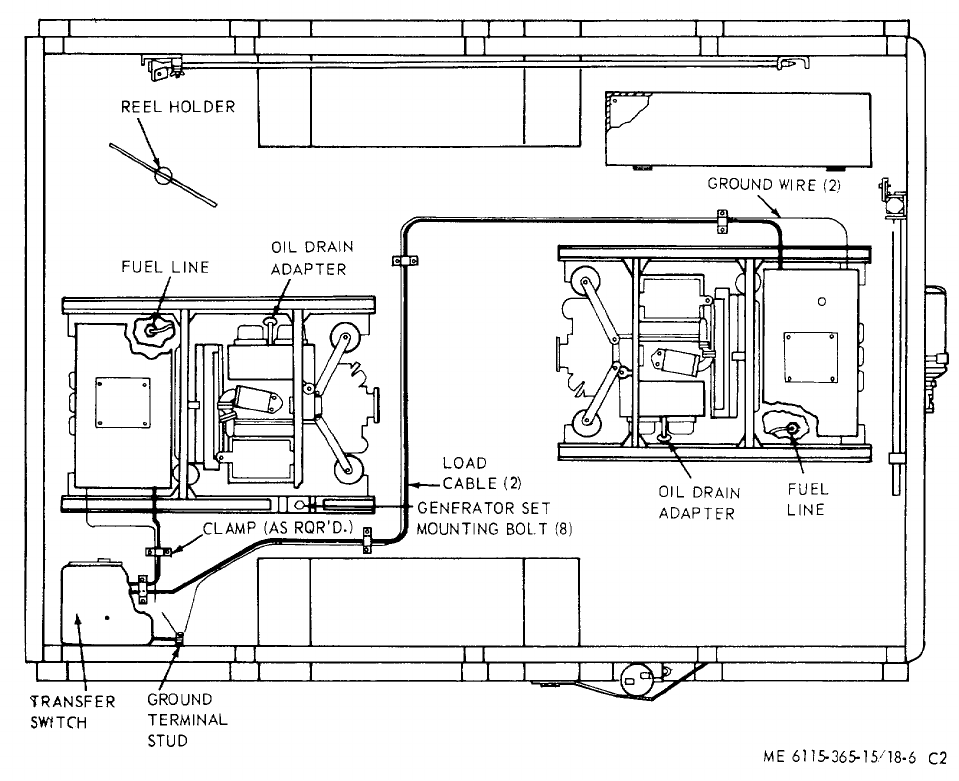
TM 5-6115-365-15
C2
Section V. DIRECT AND GENERAL SUPPORT AND DEPOT
MAINTENANCE INSTRUCTIONS
18-12. Generator Sets
a. Removal. Refer to figure 18-6 as a guide and
perform the following steps:
(1) Disconnect the fuel lines.
(2) Disconnect the electrical leads and load
cables. (3) Disconnect the oil drain adapter.
(4) Remove the 8 bolts that secure the
generator sets to the trailer and remove the generator
sets.
b. Installation. Using figure 18-6 as a guide,
perform the following steps:
(1) Secure the generator sets to the trailer
bed with the mounting hardware.
(2) Connect the oil drain adapter.
(3) Connect the electrical leads and cables.
(4) Connect the fuel lines.
18-13. Generator Transfer Switch
a. Removal and Disassembly.
(1) Tag and disconnect leads from the output
terminals to load.
(2) Remove and disassemble the transfer
switch as illustrated in figure 18-5.
Figure 18-6. PU-628/G overall component location diagram.
18-9
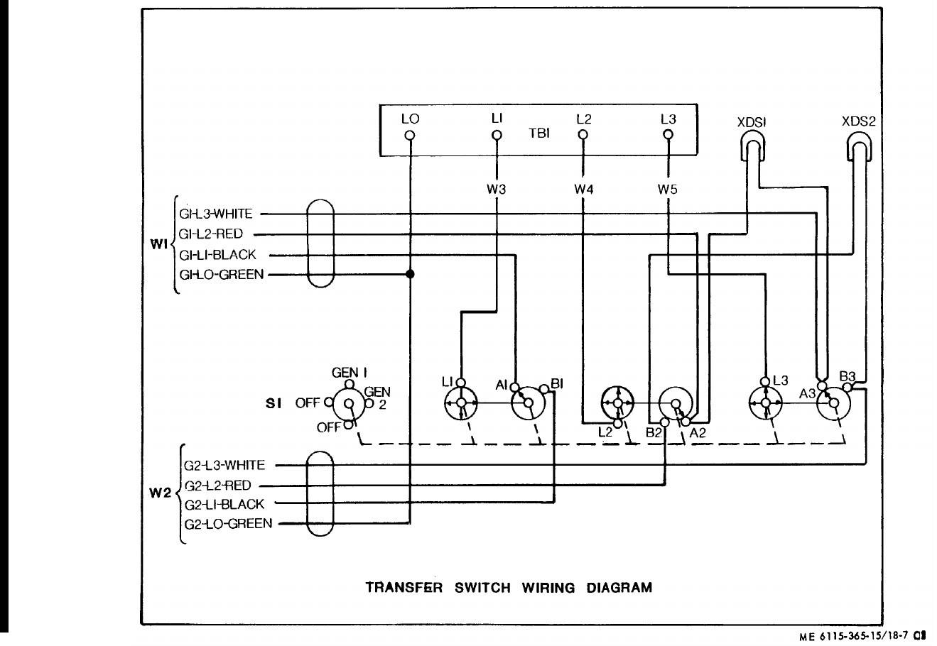
TM 5-6115-365-15
Figure 18-7. Transfer switch wiring diagram
18-10 Change 8
TM 5-6115-365-15
C2
b. Reassembly and Installation.
(1) Reassemble and install the transfer switch
as illustrated in figure 18-5.
(2) Connect load connections (Fig. 18-7).
18-14. Tarpaulin, Roof Bows, Racks, and Leg Prop
a. Removal. Remove the tarpaulin, roof bows,
racks, and leg prop (para 18-10).
b. Repair.
(1) Patch or sew rips and tears in the
tarpaulin. Replace damaged or missing ropes or straps.
Replace a tarpaulin that is too badly damaged to be
repaired. (2) Weld minor cracks or breaks in the bows
and leg prop. Straighten bent bows where possible.
Replace defective or missing pins and hardware.
Replace bows, racks, or leg prop that are damaged
beyond repair.
c. Installation. Install racks, roof bows, and leg
prop, and install tarpaulin (para 18-10).
18-11

(1) (2) (3) (4) (5) (6) (7)
FEDERAL DESCRIPTION UNIT QTY
15-DAY ORGANIZATIONAL
ILLUS-
SMR STOCK OF INC MAINTENANCE ALW RATION
CODE NUMBER USABLE MEAS IN (a) (b) (c) (d) (a) (b)
ON UNIT FIG
ITEM
REF NUMBER & MFG CODE CODE 1-5 6-20
21-50
51-100
NO. NO.
TM 5-6115-365-15
C2
PART I
REPAIR PARTS FOR ORGANIZATIONAL MAINTENANCE
00001 GROUP 01 - ENGINE
00002 0106 - ENGINE LUBRICATION SYSTEM
O4730-270-4581 ADAPTER: 1/2-10 x 1/4-18 EA 2****
00003
PO4730-908-3194 CLAMP EA 4****
00004 MS35842-11 (96906)
O4820-277-1765 COCK, PLUG, SPRING KEY: 1/4-18 x 1/4-18 EA 2****
00005
O4730-278-6317 COUPLING: 1/4 IN. EA 2****
00006
MOHOSE: 1/2-10 x 10 In., 20 in. lg EA 2
00007 SAEJ30CL30RS (81343)
MANUFACTURE FROM:
PO4730-684-6032 HOSE (10 In. required for each HOSE ASSEMBLY) FT AR SEE GRP 9501
00008
O5310-584-5272 LOCKWASHER EA 2****
00009
O4730-196-1465 NIPPLE, CLOSE EA 2****
00010
X2 ONIPPLE: 1/4 x 1-1/2 In. Ig EA 2
00011 WWN351 (81348)
O5310-282-7818 NUT EA 2****
00012
X2 O5330-684-3430 "O" RING EA 2
00013 MS28775-013 (96906)
O4730-277-6447 UNION, BULKHEAD EA 2****
00014
00015 GROUP 03 - FUEL SYSTEM
00016 0306 - TANKS, LINES, FITTINGS, AND HEADERS
X2 OBRACKET, FILLER MOUNTING EA 118-10 8
00017 13205E5080 (97403)
PO2910-911-0081 CAP, FUEL TANK: tactical vehicle fording EA 1****18-10 12
00018 MS35645-2 (96906)
X2 OCLAMP, HOSE: 1-13/16-2-3/4 range EA 218-10 43
00019 MS35842-13 (96906)
X2 OCLAMP, HOSE: 7/16-25/32 range EA 218-10 34
00020 MS35842-10 (96906)
X2 OCLAMP, LOOP, CUSHIONED: 3/4 od EA 118-10 30
00021 MS21104D12 (96906)
X2 OCLAMP, LOOP, CUSHIONED: 5/16 od EA 218-10 42
00022 MS21104D5 (96906)
X2 OCLAMP, LOOP, CUSHIONED: 5/16 od EA 318-10 48
00023 MS21104D5 (96906)
X2 OFITTING BULK HEAD: 37 degrees, 1/2-20 x 1/2 EA 218-9 19
00024 SAEJ514AFIG10C (81343)
X2 OFILLER, FUEL TANK EA 118-10 13
00025 13205E5081 (97403)
X2 OGROMMET, RUBBER: 3/4 hole diagram EA 118-10 28
00026 MS35489-120 (96906)
X2 OGUARD, FUEL GAGE EA 118-10 14
00027 13205E5083 (97403)
PO4720-580-6659 HOSE ASSEMBLY: detachment, 5/16 od x 18 Ig EA 2****18-9 28
00028 MS28741-5-0180 (96906)
18-12
(1) (2) (3) (4) (5) (6) (7)
FEDERAL DESCRIPTION UNIT QTY
15-DAY ORGANIZATIONAL
ILLUS-
SMR STOCK OF INC MAINTENANCE ALW RATION
CODE NUMBER USABLE MEAS IN (a) (b) (c) (d) (a) (b)
ON UNIT FIG
ITEM
REF NUMBER & MFG CODE CODE 1-5 6-20
21-50
51-100
NO. NO.
TM 5-6115-365-15
C2
POHOSE ASSEMBLY: detachment, 5/16 od x 56 Ig EA 1****18-10 38
00029 MS28741-5-0580 (96906)
POHOSE ASSEMBLY: detachment, 5/16 tube x 88 lg EA 1****18-10 49
00030 MS28741-5-0880 (96906)
MOHOSE, FUEL EA 118-10 44
00031 MANUFACTURE FROM:
POHOSE (3 in. required) FT SEE GRP 9501
00032 SAEJ30CLASS30R2TYPE2 (81343)
X2 OHOSE, RUBBER: 1/2 nominal id x 3/4 od x 24 EA 118-10 29
00033 MILH13444 (81348)
X2 OLOCKNUT: 37 deg flare, 1/2-20 UNF-28 EA 218-9 21
00034 SAEJ514AFIG10A (81343)
X2 ONUT, SELF-LOCKING, HEXAGON: 1/4-20 EA 218-10 7
00035 MS51922-1 (96906)
X2 ONUT, SELF-LOCKING, HEXAGON: 1/4-20 UNC-2B EA 318-10- 11
00036 MS51922-1 (96906)
X2 ONUT, SELF-LOCKING, HEXAGON: 1/4-20 UNC-2B EA 418-10 17
00037 MS51922-1 (96906)
X2 ONUT, SELF-LOCKING, HEXAGON: 3/8-16 UNC-2B EA 218-10 3
00038 MS51922-17 (96906)
X2 ONUT, SELF-LOCKING, HEXAGON: 10-32 UNF-3B EA 118-10 33
00039 MS21044N3 (96906)
X2 ONUT, SELF-LOCKING, HEXAGON:10-32 UNF-3B EA 218-10 39
00040 MS21044N3 (96906)
X2 ONUT, SELF-LOCKING, HEXAGON: 10-32 UNF-3B EA 318-10 45
00041 MS21044N3 (96906)
X2 OSCREW, CAP, HEXAGON HEAD: 1/4-20 x 1 in. 19g EA 218-10 5
00042 MS90725-8 (96906)
X2 OSCREW, CAP, HEXAGON HEAD: 1/4-20 x 5/8 EA 418-10 15
00043 MS90725-5 (96906)
X2 OSCREW, CAP, HEXAGON HEAD: 1/4-20 x 7/8 EA 318-10 9
00044 MS90725-7 (96906)
X2 OSCREW, MACHINE: pan head, 10-32 x 5/8 EA 118-10 31
00045 MS35207-264 (96906)
X2 OSCREW, MACHINE: pan head, 10-32 UNF x 5/8 EA 218-10 41
00046 MS35207-264 (96906)
X2 OSCREW, MACHINE: pan head, 10-32 x 5/8 Ig EA 318-10 47
00047 MS35207-264 (96906)
X2 OSTRAP, FUEL TANK EA 118-10 4
00048 13205E5082 (97403)
POTANK ASSEMBLY, FUEL: 2 filters EA 1****18-10 59
00049 13216E7451-2 (97403)
X2 OWASHER, FLAT, ROUND EA 218-10 2
00050 MS27183-15 (96906)
X2 OWASHER, FLAT, ROUND: 1/2 BSC size EA 218-10 60
00051 MS27183-18 (96906)
X2 OWASHER, FLAT, ROUND: 1/4 BSC size EA 318-10 10
00052 MS27183-11 (96906)
X2 OWASHER, FLAT, ROUND: 1/4 BSC size EA 218-10 6
00053 MS27183-1I (96906)
X2 OWASHER, FLAT, ROUND: 1/4 BSC size EA 418-10 16
00054 MS27183-11 (96906)
18-13

(1) (2) (3) (4) (5) (6) (7)
FEDERAL DESCRIPTION UNIT QTY
15-DAY ORGANIZATIONAL
ILLUS-
SMR STOCK OF INC MAINTENANCE ALW RATION
CODE NUMBER USABLE MEAS IN (a) (b) (c) (d) (a) (b)
ON UNIT FIG
ITEM
REF NUMBER & MFG CODE CODE 1-5 6-20
21-50
51-100
NO. NO.
TM 5-6115-365-15
C2
X2 OWASHER, FLAT, ROUND: 10-32 BSC size EA 118-10 32
00055 MS27183-8 (96906)
X2 OWASHER, FLAT, ROUND: 10-32 BSC size EA 218-10 40
00056 MS27183-8 (96906)
X2 OWASHER, FLAT, ROUND: 10-32 BSC size EA 318-10 46
00057 MS27183-8 (96906)
00058 GROUP 15 - FRAME, TOWING ATTACHMENT AND DRAWBAR
00059 1501 - FRAME ASSEMBLY
X2 O5340-999-6277 BRACKET ASSEMBLY, SLEDGE HAMMER EA 118-9 13
00060 1314E1214 (97403)
X2 OBRACKET, FUEL TANK MOUNTING EA 218-10 58
00061 13205E4953 (97403)
X2 OBRACKET, FUEL TANK MOUNTING EA 218-10 57
00063 13205154952 (97403)
X2 OBRACKET, GROUND, ROD EA 118-9 9
00064 13214E1417 (97403)
X2 OBRACKET, GROUND, ROD EA 118-9 44
00065 13214E1415 (97403)
X2 OCLAMP, CABLE EA 118-9 40
00066 13212E3572 (97403)
X2 OCLAMP, CABLE EA 418-9 49
00067 13212E3573 (97403)
X2 OCLAMP, GROUND, ROD EA 118-9 48
00068 13212E2617-1 (97403)
X2 OCLIP, SPRING, SLEDGE HAMMER EA 118-9 22
00069 13214E1213-1 (97403)
X2 OHOLDDOWN, REEL EA 118-9 53
00070 13214E1426-3 (97403)
X2 ONUT, SELF-LOCKING, HEXAGON: 1/4-20 UNC-2B EA 418-10 19
00071 MS51922-1 (96906)
X2 ONUT, SELF-LOCKING, HEXAGON: 1/4-20 UNC-2B EA 818-9 52
00072 MS51922-1 (96906)
X2 ONUT, SELF-LOCKING, HEXAGON: 1/4 UNC-2B EA 218-9 45
00073 MS51922-1 (96906)
X2 ONUT, SELF-LOCKING, HEXAGON: 1/4-20 UNC-2B EA 18-9 25
00074 MS51922-1 (96906)
X2 ONUT, SELF-LOCKING, HEXAGON: 1/4-20 UNC-2B EA 218-9 12
00075 M551922-1 (96906)
X2 ONUT, SELF-LOCKING, HEXAGON: 1/4-20 UNC-2B EA 218-9 16
00076 MS51922-17 (96906)
X2 ONUT, SELF-LOCKING, HEXAGON: 1/4-20 UNC-2B EA 218-9 39
00077 MS51922-1 (96906)
X2 ONUT, SELF-LOCKING, HEXAGON: 3/8-16 UNC-2B EA 218-10 22
00078 MS51922-17 (96906)
X2 ONUT, SELF-LOCKING, HEXAGON: 3/8-16 UNC-2B EA 218-10 22
00079 MS51922-17 (96906)
X2 ONUT, SELF-LOCKING, HEXAGON: 3/8-16 UNC-2B EA 318-10 52
00080 MS51922-17 (96906)
X2 ONUT, SELF-LOCKING, HEXAGON: 3/8-16 UNC-2B EA 418-10 60
00081 MS51922-17 (96906)
18-14

(1) (2) (3) (4) (5) (6) (7)
FEDERAL DESCRIPTION UNIT QTY
15-DAY ORGANIZATIONAL
ILLUS-
SMR STOCK OF INC MAINTENANCE ALW RATION
CODE NUMBER USABLE MEAS IN (a) (b) (c) (d) (a) (b)
ON UNIT FIG
ITEM
REF NUMBER & MFG CODE CODE 1-5 6-20
21-50
51-100
NO. NO.
TM 5-6115-365-15
C2
X2 ONUT, SELF-LOCKING, HEXAGON: 3/8-16 UNC-2B EA 318-1 37
00082 MS51922-17 (96906)
X2 ONUT, SELF-LOCKING, HEXAGON: 5/16-18 UNC-28 EA 118-9 66
00083 MS51922-9 (96906)
X2 OPLATE, CABLE MOUNTING EA 118-1 63
00084 13205E5133 (97403)
X2 OSCREW, MACHINE: 1/4-20 UNC x 1 Ig EA 218-9 47
00085 MS35190-291 (96906)
X2 OSCREW, MACHINE: 1/4-20 x 1 LG EA 218-9 10
00086 MS35190-291 (96906)
X2 OSCREW, CAP, HEXAGON HEAD: 1/4-20 x 1 lg EA 218-9 41
00087 MS90725-8 (96906)
X2 OSCREW, CAP, HEXAGON HEAD: 1/4-20 x 1 lg EA 818-9 50
00088 MS590725-8 (96906)
X2 OSCREW, CAP, HEXAGON HEAD: 1/4-20 x 3/4 EA 218-9 14
00089 MS90725-6 (96906)
X2 OSCREW, CAP, HEXAGON HEAD: 3/4-20 x 3/4 EA 1 18-9 23
00090 MS90725-6 (96906)
X2 OSCREW, CAP, HEXAGON HEAD: 1/4-20 x 7/8 EA 418-10 18
00091 MS590725-7 (96906)
X2 OSCREW, CAP, HEXAGON HEAD: 3/8-16 x 1-1/4 EA 318-10 50
00092 MS90725-62 (96906)
X2 OSCREW, CAP, HEXAGON HEAD: 3/8-16 x 1-1/4 EA 318-10 35
00093 MS90725-62 (96906)
X2 OSCREW, CAP, HEXAGON HEAD: 3/8-16 x 1-3/14 EA 218-10 20
00094 MS90725-65 (96906)
X2 OSCREW, CAP, HEXAGON HEAD: 3/8-16 x 2-1/4 EA 218-10 20
00095 MS90725-67 (96906)
X2 OSCREW, CAP, HEXAGON HEAD: 5/16-18 x 7/8 EA 118-10 64
00096 MS90725-33 (96906)
X2 OSHIELD EA 118-10 62
00097 13205E4951 (97403)
X2 OWASHER, FLAT, ROUND: 1/4 BSC size EA 418-9 20
00098 MS27183-11 (96906)
X2 OWASHER, FLAT, ROUND: 1/4 BSC size EA 818-9 51
00099 MS27183-11 (96906)
X2 OWASHER, FLAT, ROUND: 1/4 BSC size EA 218-9 46
00100 MS27183-11 (96906)
X2 OWASHER, FLAT, ROUND: 1/4 BSC size EA 118-9 24
00101 MS27183-11 (96906)
X2 OWASHER, FLAT, ROUND: 1/4 BSC size EA 218-9 11
00102 MS27183-11 (96906)
X2 OWASHER, FLAT, ROUND: 1/4 BSC size EA 218-9 15
00103 MS27183-11 (96906)
X2 OWASHER, FLAT, ROUND: 1/4 BSC size EA 218-9 42
00104 MS27183-11 (96906)
X2 OWASHER, FLAT, ROUND: 3/8 BSC size EA 618-10 51
00105 MS27183-15 (96906)
X2 OWASHER, FLAT, ROUND: 3/8 BSC size EA 418-10 6
00106 MS27183-15 (96906)
X2 OWASHER, FLAT, ROUND: 3/8 BSC size EA 318-10 36
00107 MS27183-15 (96906)
18-15

(1) (2) (3) (4) (5) (6) (7)
FEDERAL DESCRIPTION UNIT QTY
15-DAY ORGANIZATIONAL
ILLUS-
SMR STOCK OF INC MAINTENANCE ALW RATION
CODE NUMBER USABLE MEAS IN (a) (b) (c) (d) (a) (b)
ON UNIT FIG
ITEM
REF NUMBER & MFG CODE CODE 1-5 6-20
21-50
51-100
NO. NO.
TM 5-6115-365-15
C2
X2 OWASHER, FLAT, ROUND: 3/8 BSC size EA 218-10 21
00108 MS27183-15 (96906)
X2 OWASHER, FLAT, ROUND: 3/8 BSC size EA 218-10 21
00109 MS27183-15 (96906)
X2 OWASHER, FLAT, ROUND: 5/16 BSC size EA 118-10 65
00110 MS27183-12 (96906)
00111 1507 - LANDING GEAR, LEVELING JACKS
PO2590-420-8929 TRAILER LEG PROP ASSEMBLY EA 1****18-10 67
00112 13214E1206 (97403)
00113 GROUP 22 - BODY, CHASSIS OR HULL, AND ACCESSORY ITEMS
00114 2202 - ACCESSORY ITEMS
X2 OACCESSORY BOX EA 118-9 8
00115 13205E4949 (97403)
PC5120-265-7462 HAMMER HAND: double face, 8 lb EA 1****18-9 17
00116 GGGH86TYPE10CLASS1 (81348)
X2 ONUT, SELF-LOCKING, HEXAGON: 1/4-20 UNC-2B EA 418-9 7
00117 MS51922-1 (96906)
PC5975-878-3791 ROD, GROUND: 3 ft section w/attachment EA 2****18-9 54
00118 MILR11461 (81348)
X2 OSCREW, CAP, HEXAGON HEAD: 1/4-20 x 3/4 EA 418-9 5
00119 MS90725-6 (96906)
X2 OWASHER, FLAT, ROUND: 1/4 BSC size EA 418-9 6
00120 MS27183-1 (96906)
00121 2210 - DATA PLATES
X2 OPLATE, IDENTIFICATION EA 118-9 26
00122 13205E4916-21 (97403)
X2 OPLATE, IDENTIFICATION, GROUND TERMINAL EA 118-10 1
00123 13205E40918 (97403)
00124 GROUP 40 - GENERATORS
00125 4000 - MOTOR GENERATOR
X2 ONUT, SELF-LOCKING, HEXAGON: 1/2-13 UNC-2B EA 818-10 26
00126 MS51922-33 (96906)
X2 OSCREW, CAP, HEXAGON HEAD: 1/2-13 x 1-3/4 lg EA 818-10 24
00127 MS90725-114 (96906)
X2OWASHER EA 618-10 23
00128 13205E4956 (97403)
X2 OWASHER, BEVELED EA 818-10 27
00129 13206E4482-2 (97403)
X2 OWASHER, FLAT, ROUND: 1/2 BSC size EA 818-10 25
00130 MS27183-18 (96906)
00131 4019 - RADIO INTERFERENCE SUPPRESSION
X2 ONUT, PLAIN, HEXAGON: 3/8-16 UNC-2B EA 118-9 38
00132 MS16203-27 (96906)
X2 ONUT, PLAIN, HEXAGON: 3/8-16 UNC-2B EA 118-9 30
00133 MS16203-27 (96906)
X2 ONUT, PLAIN, HEXAGON: 3/8-16 UNC-2B EA 218-9 36
00134 MS16203-39 (96906)
X2 ONUT, PLAIN, WING: 3/8-16 UNC-2B EA 118-9 34
00135 MS35425-28 (96906)
18-16
(1) (2) (3) (4) (5) (6) (7)
FEDERAL DESCRIPTION UNIT QTY
15-DAY ORGANIZATIONAL
ILLUS-
SMR STOCK OF INC MAINTENANCE ALW RATION
CODE NUMBER USABLE MEAS IN (a) (b) (c) (d) (a) (b)
ON UNIT FIG
ITEM
REF NUMBER & MFG CODE CODE 1-5 6-20
21-50
51-100
NO. NO.
TM 5-6115-365-15
X2 OSCREW, CAP, HEXAGON HEAD: 3/8-16 X 3/4 EA 118-9 27
00136 MS35309-358 (96906)
X2 OSTUD, GROUNDINGEA 218-9 37
00137 13213E1223 (97403)
X2 OTERMINAL, LUG EA 318-9 32
00138 MS20659-110 (96906)
X2 OTERMINAL, LUG: No. 6 AWG, 3/8 stud EA 118-9 31
00139 MS20659-110 (96906)
X2 OWASHER, FLAT, ELECTRIC: 3/8 thd size EA 4 18-9 35
00140 AN961-616 (88044)
X2 OWASHER, FLAT: 3/8 thd size EA 118-9 29
00141 AN961-616 (88044)
X2 OWASHER, LOCK: 3/8 nominal size EA 218-9 33
00142 MS35335-91 (96906)
00143 GROUP 42 - ELECTRICAL EQUIPMENT
00144 4206 - THERMOSTATIC, AUTOMATIC AND MANUAL CONTROL DEVICES
X2 ONUT PLATE, REEL HOLDDOWN EA 118-9 4
00145 13205E4948 (97403)
X2 ONUT, SELF-LOCKING, HEXAGON: 3/8-16 UNC-2B EA 418-10 55
00146 MS51922-17 (96906)
X2 ONUT, SELF-LOCKING, HEXAGON: 1/4-20 UNC-2B EA 418-9 1
00147 MS1922-1 (96906)
X2 OPLATE EA 118-10 56
00148 13212E3569 (97403)
X2 OSCREW, CAP, HEXAGON: 1/4-20 3/4 EA 418-9 3
00149 MS90725-6 (96906)
X2 OSCREW, CAP, HEXAGON HEAD: 3/8-16 X 1-1/4 EA 418-10 53
00150 MS90725-62 (96906)
X2 OWASHER, FLAT, ROUND EA 418-9 2
00151 MS27183-11 (96906)
X2 OWASHER, FLAT, ROUND: 3/8 BSC size EA 4
00152 MS27183-15 (96906)
00153 GROUP 76 - FIRE FIGHTING EQUIPMENT COMPONENTS
00154 7638 - PORTABLE FIRE FIGHTING EQUIPMENT
PC4210-555-8837 EXTINGUISHER, FIRE: 2-3/4 w/bracket EA 1****18-9 18
00155 MIL-E52031 (81349)
00156 GROUP 95 - GENERAL USE STANDARDIZED PARTS
00157 9501 - BULK MATERIEL
PO4730-684-6032 HOSE FT ****
00158 SAEJ30CLASS30TYPE1
POHOSE, FUEL: 2-1/2 od x 3 in. Ig EA 1****
00159 SAEJ30CLASS30R2TYPE2 (81343)
Change 8 18-17
(1) (2) (3) (4) (5) (6) (7) (8) (9) (10)
DESCRIPTION 1-YR
DEPOT
QTY 30-DAY DS MAINT 30-DAY GS MAINT ALW
PER MAINT
ALW ILLUS-
TRATION
FEDERAL USABLE UNIT INC ALLOWANCE ALLOWANCE 100 PER (a) (b)
SMR
CODE STOCK
NUMBER
ON
ref NUMBER & MFR CODE CODE OF
MEAS IN
UNIT (a)
1-20 (b)
21-50 (c)
51-100 (a)
1-20 (b)
21-50 (c)
51-100
EQUIP
CNTGCY 100
EQUIP FIG.
NO. ITEM
NO.
TM 5-6115-365-15
C2
PART II
REPAIR PARTS FOR DS, OS, AND
DEPOT MAINTENANCE
00001 GROUP 01 - ENGINE
00002 0106 - ENGINE LUBRICATION SYSTEM
O4730-270-4581 ADAPTER: 1/2-10 x 1/4-18 EA 2******* *
00003
PO4730-908-3194 CLAMP EA 4* * 2* * 2 10 10
00004 MS35842-11 (96906)
O4820-277-1765 COCK, PLUG, SPRING KEY: 1/4-18 x 1/4-18 EA 2******* *
00005
O4730-278-6317 COUPLING: 1/4 IN. EA 2******* *
00006
MOHOSE: 1/2-10 x 10 in., 20 in Ig EA 2
00007 SAEJ30CL30RS (81343)
MANUFACTURE FROM:
PO4730-684-6032 HOSE (10 in. required for each HOSE
00008 ASSEMBLY) FT AR SEE GRP 9501
O5310-584-5272 LOCKWASHER EA 2******* *
O0009
O4730-196-1465 NIPPLE, CLOSE EA 2******* *
00010
X2 ONIPPLE: 1/4 x 1-1/2 in. lg EA 2
00011 WWN351 (81348)
O5310-282-7818 NUT EA 2******* *
00012
X2 O5330-684-3430 "O" RING EA 2
00013 MS28775-013 (96906)
O4730-277-6447 UNION, BULKHEAD EA 2******* *
00014
00015 GROUP 03 - FUEL SYSTEM
00016 0306 - TANKS, LINES, FITTINGS, AND HEADERS
X2 OBRACKET, FILLER MOUNTING EA 118-10 8
00017 13205E5080 (97403)
PO2910-911-0081 CAP, FUEL TANK: tactical vehicle fording EA 1* * 2* * 2 10 10 18-10 12
00018 MS35645-2 (96906)
X2 OCLAMP, HOSE: 1-13/16-2-3/4 range EA 218-10 43
00019 MS35842-13 (96906)
X2 OCLAMP, HOSE: 7/16-25/32, range EA 218-10 34
00020 MS35842-10 (96906)
X2 OCLAMP, LOOP, CUSHIONED: 3/4 od EA 118-10 30
00021 MS21104D12 (96906)
X2 OCLAMP, LOOP, CUSHIONED: 5/16 od EA 218-10 42
00022 MS21104D5 (96906)
X2 OCLAMP, LOOP, CUSHIONED: 5/16 od EA 318-10 48
00023 MS21104D5 (96906)
X2 OFITTING, BULK HEAD: 37 degrees, 1/2-20 x
00024 1/2 EA 218-9 19
SAEJ514AFIG10C (81343)
X2 OFILLER, FUEL TANK EA 118-10 13
00025 13205E5081 (97403)
X2 OGROMMET, RUBBER: 3/4 hole diagram EA 118-10 28
00026 MS35489-120 (96906)
X2 OGUARD, FUEL GAGE EA 118-10 14
00027 13205E5083 (97403)
18-18

(1) (2) (3) (4) (5) (6) (7) (8) (9) (10)
DESCRIPTION 1-YR
DEPOT
QTY
30-DAY DS MAINT
30-DAY GS MAINT
ALW
PER MAINT
ALW ILLUS-
TRATION
FEDERAL USABLE UNIT INC ALLOWANCE ALLOWANCE 100 PER (a) (b)
SMR
CODE STOCK
NUMBER
ON
REF NUMBER & MFR CODE CODE OF
MEAS
IN
UNIT (a)
1-20 (b)
21-50 (c)
51-100 (a)
1-20 (b)
21-50 (c)
51-100
EQUIP
CNTGCY
100
EQUIP FIG.
NO. ITEM
NO.
TM 5-6115-365-15
C 2,
PO4720-580-6659 HOSE ASSEMBLY: detachment, 5/16 od x 18 lg EA 2* * 2* * 2 10 10 18-9 28
00028 MS28741-5-0180 (96906)
POHOSE ASSEMBLY:detachment, 5/16 od x 56 lg EA 1* * 2* * 2 10 10 18-10 38
00029 MS28741-5-0580 (96906)
POHOSE ASSEMBLY: detachment, 5/16 tube x 88 lg EA 1* * 2* * 2 10 10 18-10 49
00030 MS28741-5-0680 (96906)
POHOSE, FUEL EA 118-10 44
00031 MANUFACTURE FROM:
POHOSE (3 in. required) FT SEE GRP 9501
00032 SAEJ30CLASS30R2TYPE2 (81343)
X2 OHOSE, RUBBER: 1/2 nominal id x 3/4 od x 24 EA 118-10 29
00033 MILH13444 (81348)
X2 OLOCKNUT: 37 deg flare, 1/2-20 UNF-2B EA 218-9 21
00034 SAEJ514AFIG10A (81343)
X2 ONUT, SELF-LOCKING, HEXAGON: 1/4-20 EA 218-10 7
00035 MS51922-1 (96906)
X2 ONUT, SELF-LOCKING, HEXAGON: 1/4-20 UNC-2B EA 318-10 11
00036 MS51922-1 (96906)
X2 ONUT, SELF-LOCKING, HEXAGON: 1/4-20 UNC-2B EA 418-10 17
00037 MS51922-1 (96906)
X2 ONUT, SELF-LOCKING, HEXAGON: 3/8-16 UNC-2B EA 218-10 3
00038 MS51922-17 (96906)
X2 ONUT, SELF-LOCKING, HEXAGON: 10-32 UNF-3B EA 118-10 33
00039 MS21044N3 (96906)
X2 ONUT, SELF-LOCKING, HEXAGON: 10-32 UNF-3B EA 218-10 39
00040 MS21044N3 (96906)
X2 ONUT, SELF-LOCKING, HEXAGON: 10-32 UNF-3B EA 318-10 45
00041 MS21044N3 (96906)
X2 OSCREW, CAP, HEXAGON, HEAD: 1/4-20 x 1 in. Ig EA 218-10 5
00042 MS90725-8 (96906)
X2 OSCREW, CAP, HEXAGON HEAD: 1/4-20 x 5/8 EA 418-10 15
00043 MS90725-5 (96906)
X2 OSCREW, CAP, HEXAGON HEAD: 1/4-20 x 7/8 EA 318-10 9
00044 MS90725-7 (96906)
X2 OSCREW, MACHINE: pan head, 10-32 x 5/8 EA 118-10 31
00045 MS35207-264 (96906)
X2 OSCREW, MACHINE: pan head, 10-32 UNF x 5/8 EA 218-10 41
00046 MS35207-264 (96906)
X2 OSCREW, MACHINE: pan head, 10-32 x 5/8 lg EA 318-10 47
00047 MS35207-264 (96906)
X2 OSTRAP, FUEL TANK EA 118-10 4
00048 13205E5082 (97403)
POTANK ASSEMBLY, FUEL: 2 filters EA 1* * 2* * 2 10 10 18-10 59
00049 13216E7451-2 (97403)
X2 OWASHER, FLAT, ROUND EA 218-10 2
00050 MS27183-15 (96906)
X2 OWASHER, FLAT, ROUND: 1/2 BSC size EA 2 18-10 60
00051 MS27183-18 (96906)
18-19

(1) (2) (3) (4) (5) (6) (7) (8) (9) (10)
DESCRIPTION 1-YR
DEPOT
QTY 30-DAY DS MAINT 30-DAY GS MAINT ALW
PER MAINT
ALW ILLUS-
TRATION
FEDERAL USABLE UNIT INC ALLOWANCE ALLOWANCE 100 PER (a) (b)
SMR
CODE STOCK
NUMBER
ON
REF NUMBER & MFR CODE CODE OF
MEAS IN
UNIT (a)
1-20 (b)
21-50
(c)
51-100
(a)
1-20 (b)
21-50
(c)
51-100
EQUIP
CNTGCY 100
EQUIP FIG.
NO. ITEM
NO.
TM 5-6115-365-15
C 2,
X2 OWASHER, FLAT, ROUND: 1/4 BSC size EA 318-10 10
00052 MS27183-11 (96906)
X2 OWASHER, FLAT, ROUND: 1/4 BSC size EA 218-10 6
00053 MS27183-11 (96906)
X2 OWASHER, FLAT, ROUND: 1/4 BSC size EA 418-10 16
00054 MS27183-11 (96906)
X2 OWASHER, FLAT, ROUND: 10-32 BSC size EA 118-10 32
00055 MS27183-8 (96906)
X2 OWASHER, FLAT, ROUND: 10-32 BSC size EA 218-10 40
00056 MS27183-8 (96906)
X2 OWASHER, FLAT, ROUND: 10/32 BSC size EA 318-10 46
00057 MS27183-8 (96906)
00058 GROUP 15 - FRAME, TOWING ATTACHMENT
AND DRAWBAR
00059 1501 - FRAME ASSEMBLY
X2 O5340-999-6277 BRACKET ASSEMBLY, SLEDGE HAMMER EA 118-9 13
00060 1314E1214 (97403)
X2 OBRACKET, FUEL TANK MOUNTING EA 218-10 58
00061 13205E4953 (97403)
X2 OBRACKET, FUEL TANK MOUNTING EA 218-9 57
00063 13205154952 (97403)
X2 OBRACKET, GROUND ROD EA 118-9 9
00064 13214E1417 (97403)
X2 OBRACKET, GROUND ROD EA 118-9 44
00065 13214E1415 (97403)
X2 OCLAMP, CABLE EA 118-9 40
00066 13212E3572 (97403)
X2 OCLAMP, CABLE EA 418-9 49
00067 13212E3573 (97403)
X2 O2590-932-7298 CLAMP, GROUND ROD EA 118-9 48
00068 13212E3617-1 (97403)
X2 O5340-914-2578 CLIP, SPRING, SLEDGE HAMMER EA 118-9 22
00069 13214E1213-1 (97403)
X2 OHOLDDOWN, REEL EA 118-9 53
00070 13214E1426-3 (97403)
X2 ONUT, SELF-LOCKING, HEXAGON: 1/4-20 UNC-2B EA 418-10 19
00071 MS51922-1 (96906)
X2 ONUT, SELF-LOCKING, HEXAGON: 1/4-20 UNC-2B EA 818-9 52
00072 MS51922-1 (96906)
X2 ONUT, SELF-LOCKING, HEXAGON: 1/4 UNC-2B EA 218-9 45
00073 MS51922-1 (96906)
X2 ONUT, SELF-LOCKING, HEXAGON: 1/4-20 UNC-2B EA 118-9 25
00074 MS51922-1 (96906)
X2 ONUT, SELF-LOCKING, HEXAGON: 1/4-20 UNC-2B EA 218-9 12
00075 MS51922-1 (96906)
X2 ONUT, SELF-LOCKING , HEXAGON: 1/4-20 UNC-2B EA 218-9 16
00076 MS51922-1 (96906)
X2 ONUT, SELF-LOCKING, HEXAGON: 1/4-20 UNC-2B EA 218-9 39
00077 MS51922-1 (96906)
18-20

(1) (2) (3) (4) (5) (6) (7) (8) (9) (10)
DESCRIPTION 1-YR
DEPOT
QTY 30-DAY DS MAINT 30-DAY GS MAINT ALW
PER MAINT
ALW ILLUS-
TRATION
FEDERAL USABLE UNIT INC ALLOWANCE ALLOWANCE 100 PER (a) (b)
SMR
CODE STOCK
NUMBER
ON
REF NUMBER & MFR CODE CODEOF
MEAS IN
UNIT (a)
1-20 (b)
21-50
(c)
51-100
(a)
1-20 (b)
21-50
(c)
51-100
EQUIP
CNTGCY 100
EQUIP FIG.
NO. ITEM
NO.
TM 5-6115-365-15
C 2,
X2 ONUT, SELF-LOCKING, HEXAGON: 3/8-16 UNC-2B EA 218-10 22
00078 MS51922-17 (96906)
X2 ONUT, SELF-LOCKING, HEXAGON: 3/8-16 UNC-2B EA 218-10 22
00079 MS51922-17 (96906)
X2 ONUT, SELF-LOCKING, HEXAGON: 3/8-16 UNC-2B EA 318-10 52
00080 MS51922-17 (96906)
X2 ONUT, SELF-LOCKING, HEXAGON: 3/8-16 UNC-2B EA 418-10 60
00081 MS51922-17 (96906)
X2 ONUT, SELF-LOCKING, HEXAGON: 3/8-16 UNC-2B EA 318-10 37
00082 MS51922-17 (96906)
X2 ONUT, SELF-LOCKING, HEXAGON: 5/16-18 UNC-2B EA 118-10 66
00083 MS51922-9 (96906)
X2 OPLATE, CABLE MTG. EA 118-10 63
00084 13205E5133 (97403)
X2 OSCREW, MACHINE: 1/4-20 UNC x 1 lg EA 218-9 47
00085 MS35190-291 (96906)
X2 OSCREW, MACHINE: 1/4-20 x 1 lg EA 218-9 10
00086 MS35190-291 (96906)
X2 OSCREW, CAP, HEXAGON HEAD: 1/4-20 x 1 lg EA 218-9 41
00087 MS90725-8 (96906)
X2 OSCREW, CAP, HEXAGON HEAD: 1/4-20 x 1 Ig EA 818-9 50
00088 MS90725-8 (96906)
X2OSCREW, CAP, HEXAGON HEAD: 1/4-20 x 3/4 EA 218-9 14
00089 MS90725-6 (96906)
X2 OSCREW, CAP, HEXAGON HEAD: 1/4-20 x 3/4 EA 118-9 23
00090 MS90725-6 (96906)
X2 OSCREW, CAP, HEXAGON HEAD: 1/4-20 x 7/8 EA 418-10 18
00091 MS90725-7 (96906)
X2 OSCREW, CAP, HEXAGON HEAD: 3/8-16 x 1-1/4 EA 318-10 50
00092 MS90725-62 (96906)
X2 OSCREW, CAP, HEXAGON HEAD: 3/8-16 x 1-1/4 EA 318-10 35
00093 MS90725-62 (96906)
X2 OSCREW, CAP, HEXAGON HEAD: 3/8-16 x 1-3/4 EA 218-10 20
00094 MS90725-65 (96906)
X2 OSCREW, CAP, HEXAGON HEAD: 3/8-16 x 2-1/4 EA 218-10 20
00095 MS90725-67 (96906)
X2 OSCREW, CAP, HEXAGON HEAD: 5/16-18 x 7/8 EA 118-10 64
00096 MS90725-33 (96906)
X2 OSHIELD EA 118-10 62
00097 13205E4951 (97403)
X2 OWASHER, FLAT, ROUND: 1/4 BSC size EA 418-9 20
00098 MS27183-11 (96906)
X2 OWASHER, FLAT, ROUND: 1/4 BSC size EA 818-9 51
00099 MS27183-11 (96906)
X2 OWASHER, FLAT, ROUND: 1/4 BSC size EA 218-9 46
00100 MS27183-11 (96906)
X2 OWASHER, FLAT, ROUND: 1/4 BSC size EA 118-9 24
00101 MS27183-11 (96906)
X2 OWASHER, FLAT, ROUND: 1/4 BSC size EA 218-9 11
00102 MS27183-11 (96906)
X2 OWASHER, FLAT, ROUND: 1/4 BSC size EA 218-9 15
00103 MS27183-11 (96906)
18-21
(1) (2) (3) (4) (5) (6) (7) (8) (9) (10)
DESCRIPTION 1-YR
DEPOT
QTY 30-DAY DS MAINT 30-DAY GS MAINT ALW
PER MAINT
ALW ILLUS-
TRATION
FEDERAL USABLE UNIT INC ALLOWANCE ALLOWANCE 100 PER (a) (b)
SMR
CODE STOCK
NUMBER
ON
REF NUMBER & MFR CODE CODE OF
MEAS IN
UNIT (a)
1-20 (b)
21-50 (c)
51-100 (a)
1-20 (b)
21-50 (c)
51-100
EQUIP
CNTGCY 100
EQUIP FIG.
NO. ITEM
NO.
TM 5-6115-365-15
C 2,
X2 OWASHER, FLAT, ROUND: 1/4 BSC size EA 218-9 42
00104 MS27183-11 (96906)
X2 OWASHER, FLAT, ROUND: 3/8 BSC size EA 618-10 51
00105 MS27183-15 (96906)
X2 OWASHER, FLAT, ROUND: 3/8 BSC size EA 418-10 61
00106 MS27183-15 (96906)
X2 OWASHER, FLAT, ROUND: 3/8 BSC size EA 318-10 36
00107 MS27183-15 (96906)
X2 OWASHER, FLAT, ROUND: 3/8 BSC size EA 218-10 21
00108 MS27183-15 (96906)
X2 OWASHER, FLAT, ROUND: 3/8 BSC size EA 218-10 21
00109 MS27183-15 (96906)
X2 OWASHER, FLAT, ROUND: 5/16 BSC size EA 118-10 65
00110 MS27183-12 (969006)
00111 1507 - LANDING GEAR, LEVELING JACKS
PO2590-420-8929 TRAILER LEG, PROP ASSEMBLY EA 1* * 2* * 2 10 10 18-10 67
00112 13214E1206 (97403)
00013 GROUP 18 - BODY, CAB, HOOD, AND HULL
00114 1810 - CARGO BODY
X2 DR 2330-738-9509 TRAILER EA 118-9 55
00115 13205E4955 (97403)
00116 GROUP 22 - BODY, CHASSIS OR HULL, AND
ACCESSORY ITEMS
00117 2202 - ACCESSORY ITEM
X2 OACCESSORY BOX EA 118-9 8
00118 13205E4949 (97403)
PC5120-265-7462 HAMMER HAND: double face, 8 lb EA 1* * 2* * 2 10 10 18-9 17
00119 GGGH86TYPE10CLASS1 (81348)
X2 ONUT, SELF-LOCKING, HEXAGON: 1/4-20 UNC-2B EA 418-9 7
00120 MS51922-1 (96906)
PC5975-878-3791 ROD, GROUND: 3 ft section w/attachment EA 2* * 2* * 2 10 10 18-9 54
00121 MILR11461 (81348)
X2 OSCREW, CAP, HEXAGON HEAD: 1/4-20 x 3/4 EA 418-9 5
00122 MS90725-6 (96906)
X2 OWASHER, FLAT, ROUND: 1/4 BSC size EA 418-9 6
00123 MS27183-11 (96906)
00124 2210 - DATA PLATES
X2 OPLATE, IDENTIFICATION EA 118-9 26
00125 13205E4916-21 (97403)
X2 OPLATE, IDENTIFICATION, GROUND TERMINAL EA 118-10 1
00126 13205E40918 (97403)
X2 FPLATE, INFORMATION WIRING DIAGRAM EA 1
00127 13212E1499 (97403)
00128 GROUP 40 - GENERATORS
00129 4000 - MOTOR GENERATOR
X2 FR 6115-017-8237 GENERATOR SET: 3 kw, 60 hz md EA 218-9 55
00130 MILG52367TYPE1 (81349)
X2 ONUT, SELF-LOCKING, HEXAGON: 1/2-13 UNC-2B EA 818-10 26
00131 MS51922-33 (96906)
18-22
(1) (2) (3) (4) (5) (6) (7) (8) (9) (10)
DESCRIPTION 1-YR
DEPOT
QTY 30-DAY DS MAINT 30-DAY GS MAINT ALW
PER MAINT
ALW ILLUS-
TRATION
FEDERAL USABLE UNIT INC ALLOWANCE ALLOWANCE 100 PER (a) (b)
SMR
CODE STOCK
NUMBER
ON
REF NUMBER & MFR CODE CODE OF
MEAS IN
UNIT (a)
1-20 (b)
21-50
(c)
51-100
(a)
1-20 (b)
21-50
(c)
51-100
EQUIP
CNTGCY 100
EQUIP FIG.
NO. ITEM
NO.
TM 5-6115-365-15
X2 OSCREW, CAP, HEXAGON HEAD: EA 818- 24
1/2-13 X 1-3/4 LG 10
00132 MS90725-114 (96906)
X2 OWASHER EA 618- 23
00133 13205E4956 (97403) 10
X2 OWASHER, BEVELED EA 818- 27
00134 13206E4482-2 (97403) 10
X2 OWASHER, FLAT, ROUND: 1/2 BSC SIZE EA 818- 25
00135 MS27183-18 (96906) 10
00136 4019 - RADIO INTERFERENCE
SUPPRESSION
X2 ONUT, PLAIN, HEXAGON: 3/8-16 UNC-3B EA 118- 38
00137 MS16203-27 (96906) 9
X2 ONUT, PLAIN, HEXAGON: 3/8-16 UNC-2B EA 118- 30
00138 MS16203-27 (96906) 9
X2 ONUT, PLAIN, HEXAGON: 3/8-16 UNC-2B EA 218- 36
00139 MS16203-39 (96906) 9
X2 ONUT, PLAIN, WING: 3/8-16 UNC-2B EA 118- 34
00140 MS35425-28 (96906) 9
X2 OSCREW, CAP, HEXAGON HEAD: 3/8-16 x 3/4 EA 118- 27
00141 MS35309-358 (96906) 9
X2 OSTUD, GROUNDING EA 218- 37
00142 13213E1223(97403) 9
X2 OTERMINAL, LUG EA 318- 32
00143 MS20659-110 (96906) 9
X2 OTERMINAL, LUG: No. 6 AWG, 3/8 STUD EA 118- 31
00144 MS20659-110 (96906) 9
X2 OWASHER, FLAT, ELECTRIC: 3/8 THD SIZE EA 18- 35
00145 AN961-616 (88044) 9
X2 OWASHER. FLAT: 3/8 THD SIZE EA 18- 29
00146 AN961-616(88044) 9
X2 OWASHER, LOCK: 3/8 NOM. SIZE EA 18- 33
00147 MS35335-91 (96906) 9
00148 GROUP 42- ELECTRICAL EQUIPMENT
00149 4206 - THERMOSTATIC, AUTOMATIC AND
MANUAL CONTROL DEVICES
X2 FBOX EA 118- 16
00150 13205E5077(97403) 8
X2 FCOVER EA 118- 29
00151 13205E5078(97403) 8
X2 FDISTRIBUTION BOX EA 118- 43
00152 13205E5079-2 (97403) 9
AFCABLE, GENERATOR: No. 1 To Distribution
00153 BOX, 2-1/2 FT EA 118- 14
13212E3570-2 (97403) 8
AO FCABLE, GENERATOR: No. 2 To Distribution
00154 BOX, 11 FT EA 118- 15
13212E3571-3 8
MOCABLE FT
00154A MANUFACTURE FROM:
CABLE FT AR SEE GROUP 9501
CO-04HGF (4/10) (81349)
PA F5940-143-4794 TERMINAL LUG EA 318- 15B
00154B MS25036-112 (96906) 8
Change 10 18-23
(1) (2) (3) (4) (5) (6) (7) (8) (9) (10)
DESCRIPTION 1-YR
DEPOT
QTY 30-DAY DS MAINT 30-DAY GS MAINT ALW
PER
MAINT
ALW ILLUS-
TRATION
FEDERAL USABLE
UNIT
INC ALLOWANCE ALLOWANCE 100 PER (a) (b)
SMR
CODE STOCK
NUMBER
ON
REF NUMBER & MFR CODE CODE OF
MEAS IN
UNIT (a)
1-20 (b)
21-50 (c)
51-100 (a)
1-20 (b)
21-50 (c)
51-100
EQUIP
CNTGCY 100
EQUIP
FIG.
NO.
ITEM
NO.
TM 5-6115-365-15
PA F
00154C 5940-143-4777 TERMINAL LUG EA 118- 15C
MS25036-157 (96906) 8
PA F
00154D 5970-822-2775 INSULATION FT 118-
15D
M23053/5-110-9 (81349) 8
PA F
00154E 5970-082-3942 INSULATION FT 118- 15E
M23053/5-105-9 (81349) 8
XFGASKET EA 118- 17
00155 13212E3610 8
X2 FLEAD, ELECTRICAL: NO. W3 EA 118- 9
00156 13212E3567-1 (97403) 8
X2 FLEAD, ELECTRICAL: NO. W4 EA 118- 10
00157 13212E2567-2 (97403) 8
X2 FLEAD, ELECTRICAL: NO. W5 EA 118- 11
00158 13212E3567-3(97403) 8
X2 FLIGHT AND WIRE EA 218- 1
00159 13212E3560 8
X2 FNUT, PLAIN, HEXAGON EA 618- 26
00160 MS35649-202 (96906) 8
X2 FNUT, PLAIN, HEXAGON: 1/4-20 UNC-2B EA 418- 8
00161 MS35691-1 (96906) 8
X2 FNUT, PLAIN, HEXAGON: 1/4-20 UNC-2B EA 818- 23
00162 FFN836TYPE2 (81348) 8
X2 0NUT PLATE, REEL HOLDDOWN EA 118- 4
00163 13205E4948 (97403) 9
X2 0NUT, SELF-LOCKING, HEXAGON: EA 418- 55
3/8-16 UNC-2B 10
00164 MS51922-17 (96906)
X2 0NUT, SELF-LOCKING, HEXAGON: EA 418- 1
1/4-20 UNC-2B 9
00165 MS51922-1 (96906)
X2 FPACKING, PREFORMED, "O" RING EA 118- 28
00166 MS28775-111 (96906) 8
X2 FPACKING, PREFORMED, ‘OO' RING EA 218- 12
00167 MS28775-122 (96906) 8
X2 FPACKING, PREFORMED, "O" RING EA 418- 3
00168 MS28775-011(96906) 8
X2 0PLATE EA 118- 56
00169 13212E3569 (97403) 10
X2 0SCREW, CAP, HEXAGON HEAD: 1/4-20x 3/4 EA 418- 3
00170 MS90725-6 (96906) 9
X2 0SCREW, CAP, HEXAGON HEAD: EA 418- 53
00171 MS90725-62 (96906) 10
X2 FSCREW, MACHINE: PAN HEAD, 1/4-20 x 3/4 EA 418- 2
00172 MS35206-281 (96906) 8
X2 FSCREW, MACHINE: PAN HEAD, 10-24x 1 LG EA 618- 20
00173 MS35206-267 (96906) 8
X2 FSCREW, MACHINE: PAN HEAD, 10-32 x 1/2 LG EA 16 18- 4
00174 MS35207-263 (96906) 8
X2 FSTUFFING, TUBE EA 218- 13
00175 13212E3582-4(97403) 8
18-24 Change 10
(1) (2) (3) (4) (5) (6) (7) (8) (9) (10)
DESCRIPTION 1-YR
DEPOT
QTY 30-DAY DS MAINT 30-DAY GS MAINT ALW
PER MAINT
ALW ILLUS-
TRATION
FEDERAL USABLE UNIT INC ALLOWANCE ALLOWANCE 100 PER (a) (b)
SMR
CODE STOCK
NUMBER
ON
REF NUMBER & MFR CODE CODE OF
MEAS IN
UNIT (a)
1-20 (b)
21-50
(c)
51-100
(a)
1-20 (b)
21-50
(c)
51-100
EQUIP
CNTGCY 100
EQUIP FIG.
NO. ITEM
NO.
TM 5-6115-365-15
P2 F5930-878-6722 SWITCH, ROTARY: 30 AMP EA 1•••• 3 2 18- 27
00176 13205E5022(97403) 8
X2 FTERMINAL, BOARD EA 118- 18
00177 13212E3606 8
X2 FTERMINAL, LOAD EA 418- 19
00178 13208E5820-6 (97403) 8
X2 OWASHER, FLAT, ROUND EA 418- 2
00179 MS271893-11 (96906) 9
X2 FWASHER, FLAT, ROUND: 10-32 BSC SIZE EA 16 18- 6
00180 MS27183-8 (96906) 8
X2 FWASHER, FLAT, ROUND: 10 NOM. SIZE EA 12 18- 21
00181 MS27183-8 (96906) 8
X2 OWASHER, FLAT, ROUND: 3/8 BSC SIZE EA 418- 54
00182 MS27183-15(96906) 10
X2 FWASHER, LOCK, FLAT: 1/4 NOM. SIZE EA 418- 22
00183 MS35333-108 (96906) 8
X2FWASHER, FLAT, ROUND: 1/4-20 BSC SIZE EA 418- 7
00184 MS27183-11 (96906) 8
X2 FWASHER, LOCK; SPRING HELICAL, 10 NOM. EA 618- 25
size 8
00185 MS35338-43 (96906)
X2 FWASHER, LOCK, SPRING: NO. 10 NOM. EA 16 18- 5
SIZE 8
00186 MS35338-43 (96906)
X2 FWASHER, LOCK; 1/4 NOM. SIZE EA 818- 24
00187 MS35338-101 (96906) 8
00188 GROUP 76- FIRE FIGHTING
EQUIPMENT COMPONENTS
00189 7638 - PORTABLE FIRE
FIGHTING EQUIPMENT
PC4210-555-8837 EXTINGUISHER, FIRE: 2-3/4W/BRACKET EA 1• • 2• • 2 10 10 18- 18
00190 MILE52031 (81349) 9
00191 GROUP 95 - GENERAL USE
STANDARDIZED PARTS
00192 9501 - BULK MATERIEL
PO4730-684-6032 HOSE FT ••••••10 10
00193 SAEJ30CLASS30TYPE1
POHOSE, FUEL: 2-1/2 OD x 3 IN. LG EA 1••••••• •
00194 SAEJ30CLASS30R2TYPE2 (81343)
PA F6145-643-0030 CABLE EA V ••••••• •
00195 CO-04HGF (4/10) (81349)
PA F5970-822-2775 INSULATION FT V••••••• •
00196 M23053/5-110-9 (81349)
PA F5970-082-3942 INSULATION FT V••••••• •
001975 M23053/5-105-9 (81349)
Change 10 18-25
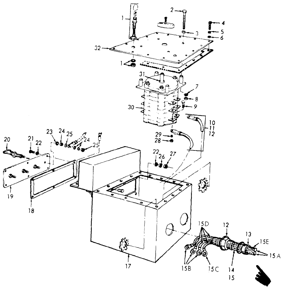
TM 5-6115-365-15
Figure 18-8. Generator transfer switch.
18-26 Change 10
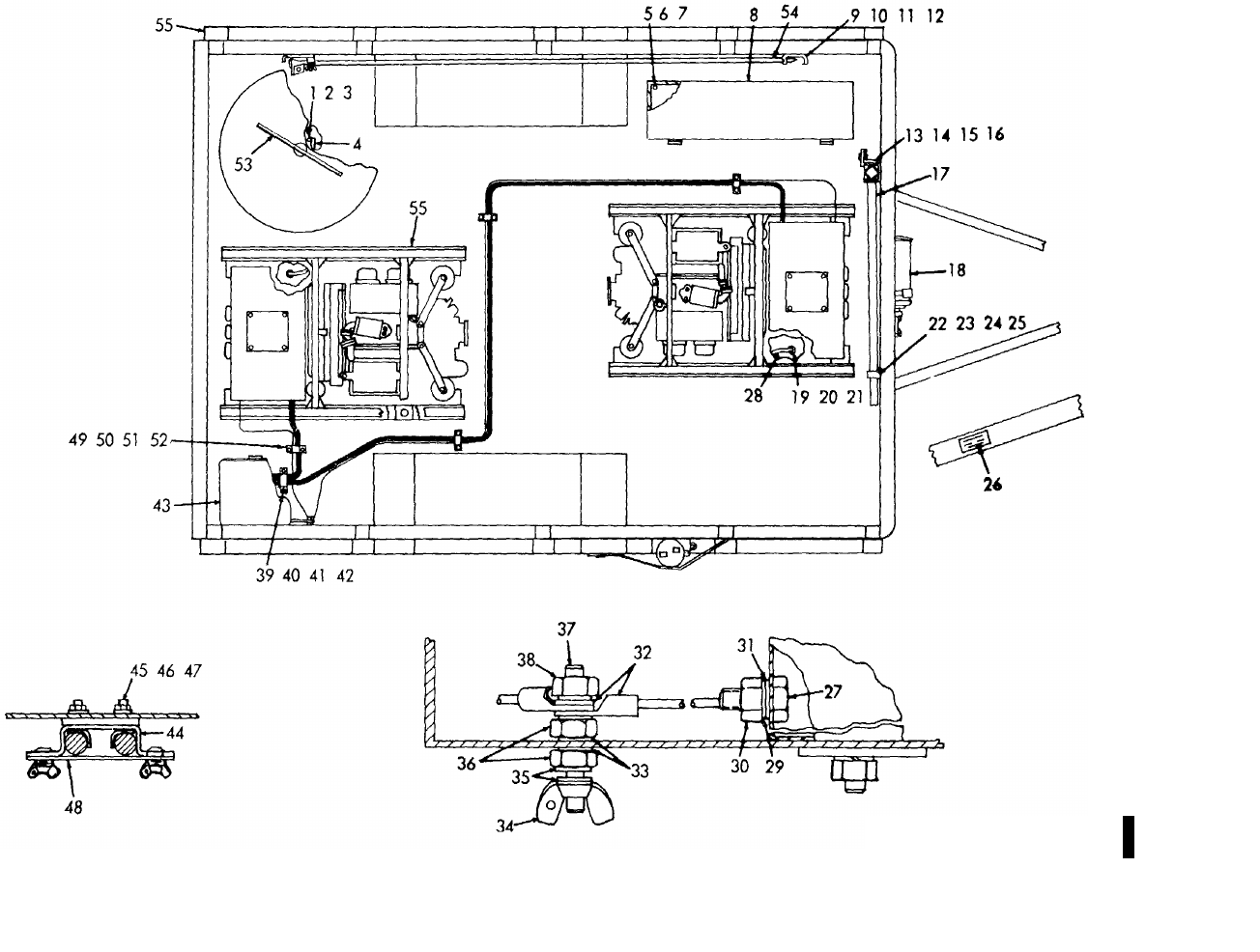
TM 5-6115-365-15
C 2,
Figure 18-9. Power unit components.
ME 6115-305-15/18-9, C2
18-27
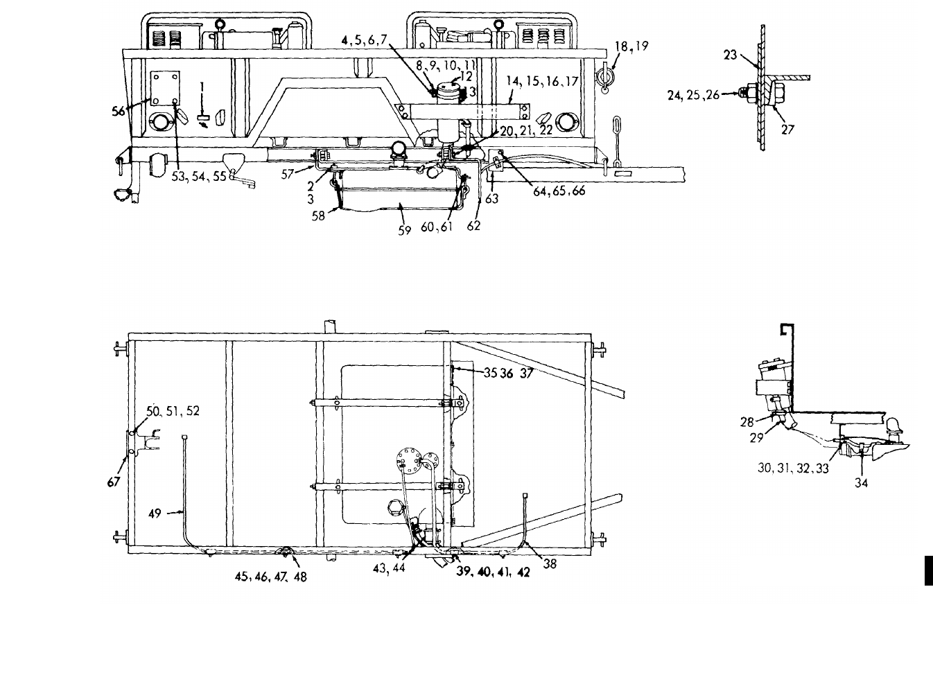
TM 5-6115-365-15
C 2,
Figure 18-10. Power unit trailer components.
ME 6115-365-15/18-10, C2
18-28

TM 5-6115-365-15
CHAPTER 19
GENERATOR SET PU-629/G
Section I. DESCRIPTION AND DATA
19-1. Description
a. General. The PU-629/G is a self-contained
mobile, general purpose power supply (Fig. 19-1). The
set is comprised of two 5 kW Model SF 5.0 MD Military
Standard generator sets, mounted on a 1 1/2 ton M103A
trailer, and includes the components listed in table 19-1.
The generators are powered by directly coupled, 2-
cylinder, 10 hp, Military Standard Model 2A042 engines.
A power transfer switch is provided for connecting the
generator outputs to a common load.
b. Engines. For description and maintenance
information pertaining to the engines, refer to
TM 5-2805-258-14.
c. Generators. For description, operation, and
maintenance information not covered in this chapter,
refer to TM 5-6115-332-14.
d. Trailer. For description and trailer maintenance
information not covered in this chapter, refer to
TM 9-2330-213-14.
e. Lubrication. For lubrication information, refer to
TM 5-6115-332-14. For engine lubrication instructions,
refer to TM 5-2805-258-14 and LO 5-2805-258-12. For
trailer lubrication information, refer to LO 9-2330-213-12.
19-2. Tabulated Data
Table 19-1 lists the components for PU-629/G.
Table 19-1. PU-629/G Components
FSN Qty Nomenclature
2330-141-8052 1Trailer: M103A
6115-074-8830 2Generator: 5 kW,
Model SF 5.0 MD
2590-741-1037 1Leg Prop assembly, trailer
4210-555-8837 2Fire extinguisher
5975-878-3791 2Ground rod (w/attachments)
5120-265-7462 1Sledge hammer
FSN not assigned 2Fuel tank assembly
2540-00-459-5946 1Tarpaulin
Change 10 19-1
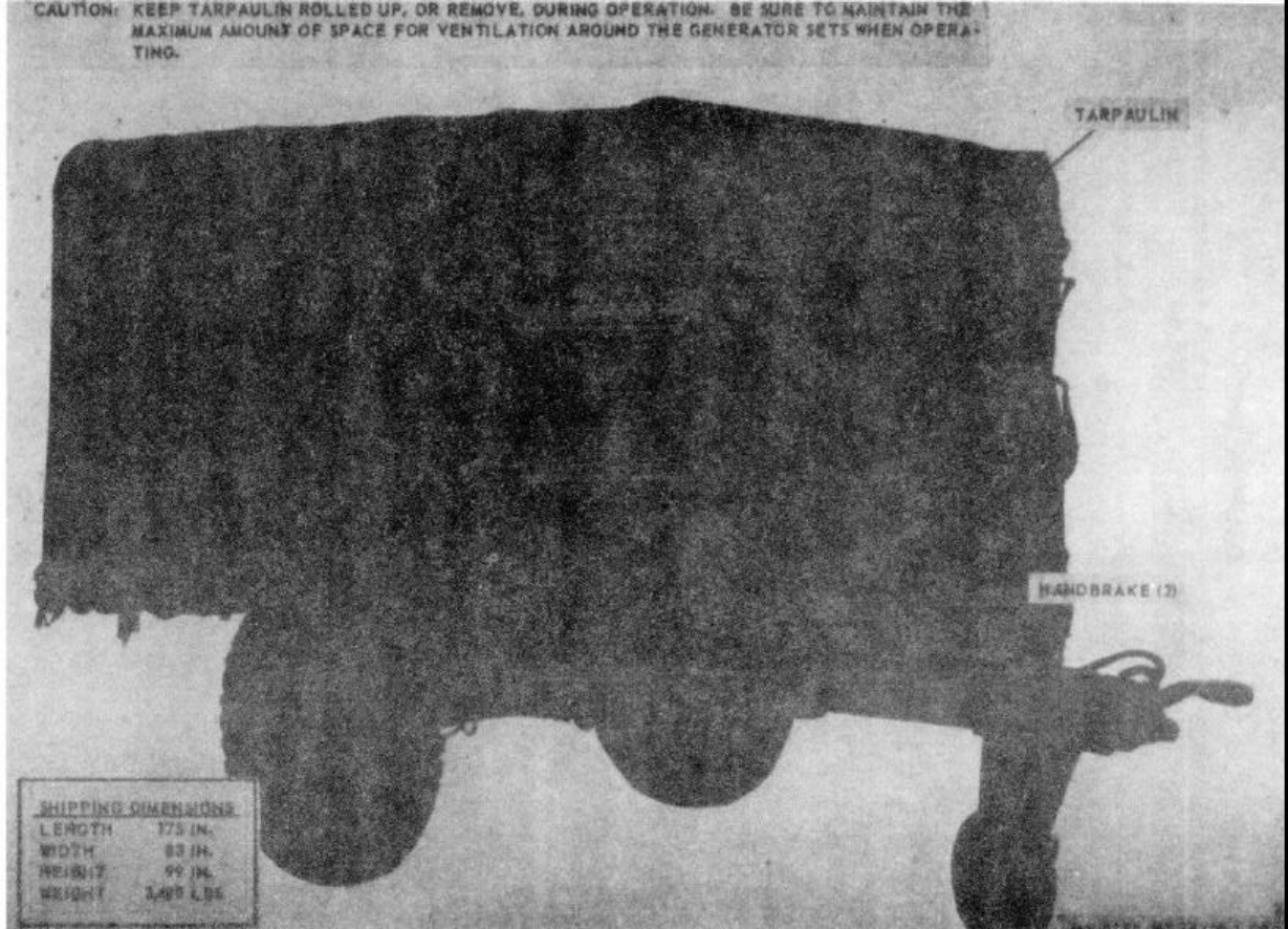
TM 5-6115-365-15
C 2,
Figure 19-1. PU-629/G. right front, 3/4 view.
19-2
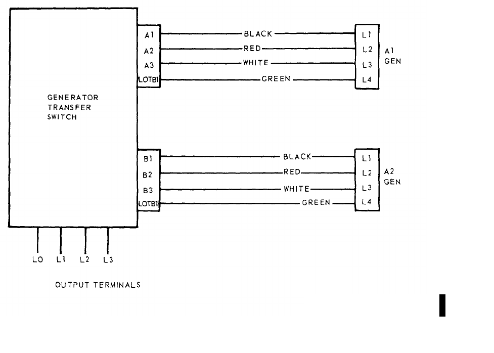
TM 5-6115-365-15
C 2,
Section II. OPERATING INSTRUCTIONS
19-3. Setting-up Instructions
a. Leveling.
(1) Locate the trailer on as level a surface as
possible in order for the generator to operate efficiently.
(2) Set brakes and block wheels securely to
prevent any movement. Operate handbrakes at weekly
intervals to assure freedom of linkage.
(3) Pull leg support down and adjust length
for firm contact with ground.
WARNING
Wheels must be blocked, brakes set,
and leg prop down in support
position before attempting to roll up
tarpaulin and before starting to set-
up or assemble the equipment for
operation.
b. Preparation for Starting.
(1) Roll up tarpaulin and remove splash shield
as shown in figure 19-3.
(2) Remove all loose auxiliary items and
anything else that might block the free circulation of air
through the trailer and around the generator sets.
CAUTION
It is of foremost importance that
there be free circulation of air around
the generator sets at all times during
operation. Inadequate ventilation is a
major cause of damage to the
equipment.
(3)Be sure transfer switch load cables are
connected to the generator sets as illustrated in
figure 19-2.
Figure 19-2. Interconnection diagram, transfer switch-to-generators.
ME 6115-365-15/19-2 C2
19-3
TM 5-6115-365-15
C 2
c. Grounding. WARNING
Never operate the generator set until
it has been properly grounded.
Electrical defects in the load lines or
equipment can cause death by
electrocution when contact is made
with an ungrounded system.
(1) The generator set must be grounded prior
to operation. The ground may be any of three methods,
depending on the location and terrain.
(a)A ground rod driven to a depth of 8
feet. (b)An underground metallic water
piping system. (c)A metal plate (9 sq. ft.) buried at a
depth of 4 feet.
(2) The ground lead must be No. 6 AWG
copper wire bolted or clamped to the rod, plate, or piping
system. (3) Connect the other end of the ground lead
to the generator set ground terminal stud as shown in
figure 19-3.
(4) Be sure that both generators are
connected to the generator set ground terminal stud, as
shown in figure 19-3.
d. Fuel Hose Connection. Connect the fuel hoses
as illustrated in figure 19-4.
WARNING
Never operate the generator set in an
enclosed area unless the exhaust
gases are piped to the outside.
Inhalation of exhaust fumes will
result in serious illness or death.
19-4. Starting
a. Perform the setting-up and pre-starting
procedures (para 19-3).
b. Be sure the generator transfer switch is OFF
(fig. 19-3).
c. Start the generator set as instructed in
TM 5-6115-332-12.
19-5. Stopping
a. Turn the generator transfer switch OFF or in
position to select a standby generator (fig. 19-3).
b. Stop the generator as instructed in
TM 5-6115-332-12.
19-6. Operation
a. Start the generator (para 19-4) and position the
transfer switch to the desired generator.
b. Operate the generator as instructed in
TM 5-6115-332-12.
c. Perform the fuel connection and transfer
procedure as instructed in figure 19-4.
19-4
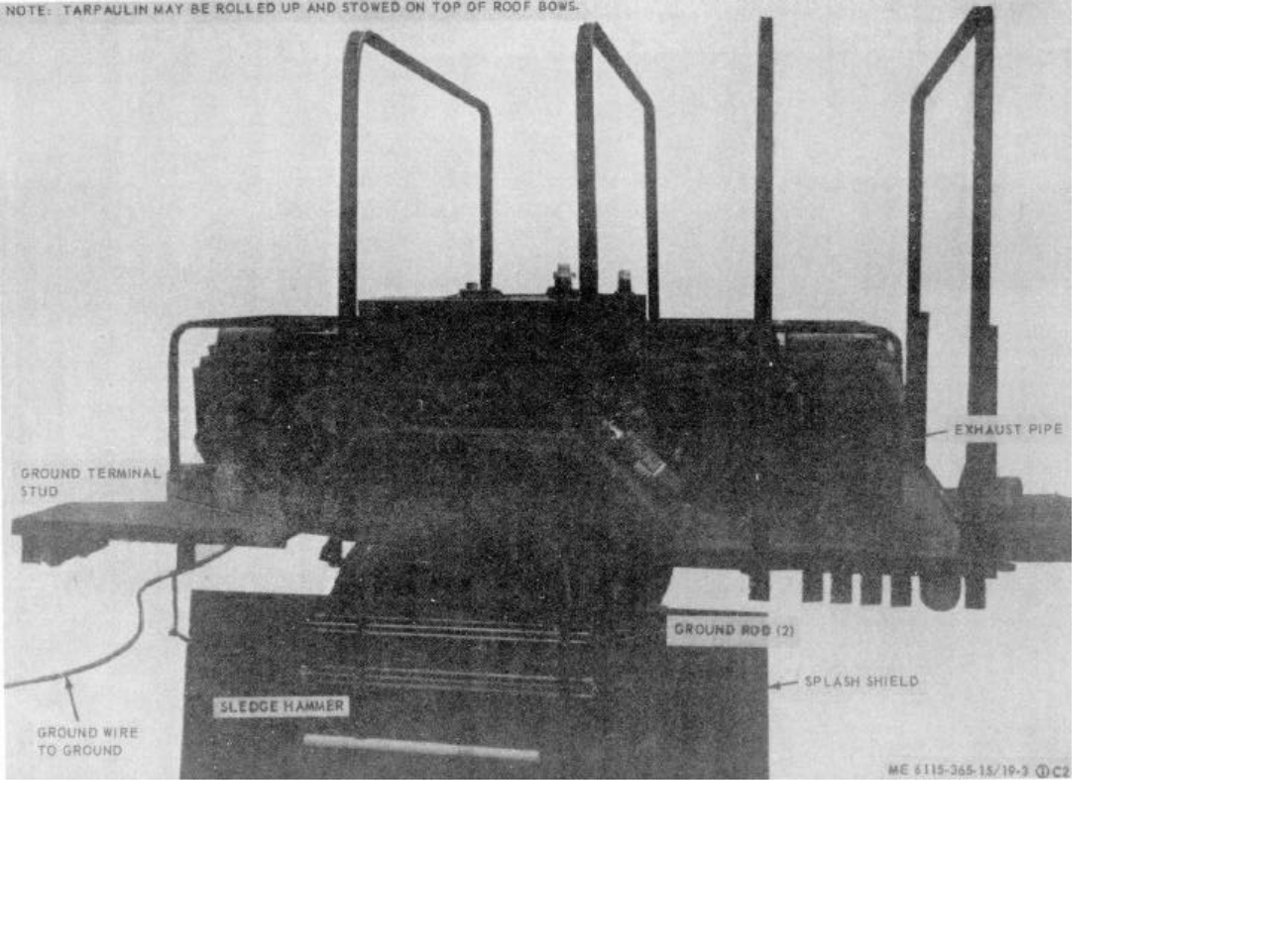
(Figure 19-3 Sheet 1 of 2)
(Figure 19-3 Sheet 1 of 2)
ME 6115-365-15/19-3 (1) C2
TM 5-6115-365-15
C 2,
Figure 19-3. PU-629/C set up for operation (sheet 1 of 2).
19-5
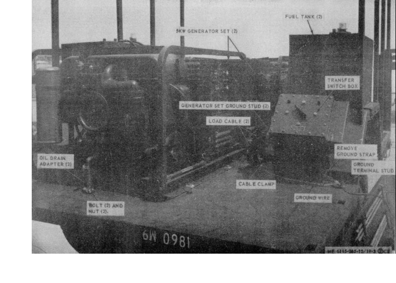
ME 6115-365-15/19-3 (2) C2
TM 5-6115-365-15
C 2,
Figure 19-3. PU-926/C Set up for operation (sheet 2 of 2).
19-6
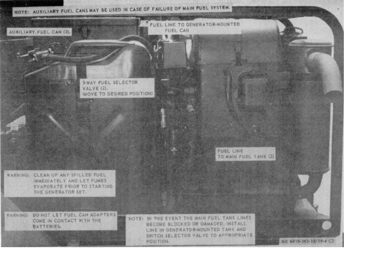
ME 6115-365-15/19-4 C2
TM 5-6115-365-15
C 2,
Figure 19-4. Fuel system connection and transfer procedure
19-7
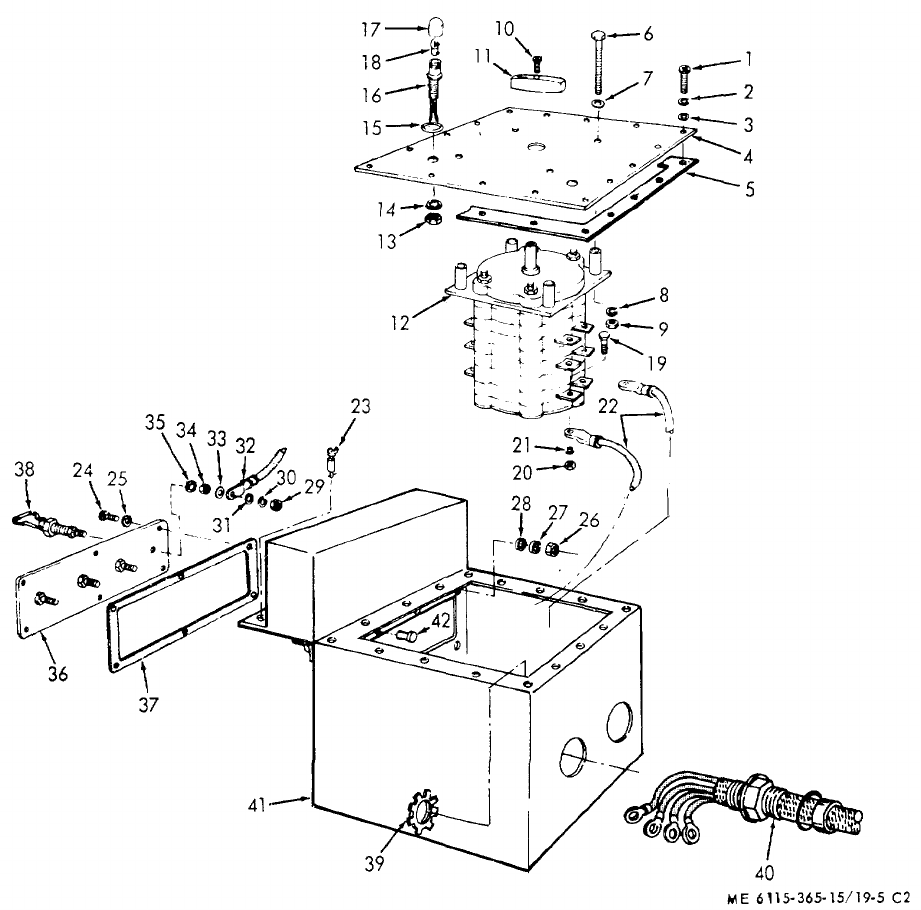
TM 5-6115-365-15
C 2,
Section III. OPERATOR'S MAINTENANCE INSTRUCTIONS
19-7. Transfer Switch Indicating Lamps
a. Removal. Remove lens and remove indicator
lamp as illustrated in figure 19-5. b. Installation. Install the indicator lamp and lens
as illustrated in figure 19-5.
1 Screw 10 Screw 19 Screw 28 Flat washer 37 Gasket
2 Lockwasher 11 Knob 20 Hex nut 29 Hex nut 38 Terminal lug
3 Flat washer 12 Transfer switch 21 Lockwasher 30 Lockwasher 39 Locknut
4 Cover 13 Hex nut 22 Electrical lead 31 Flat washer 40 Stuffing tube assy
5 Gasket 14 Lockwasher 23 Fastener 32 Electrical lead 41 Transfer switch box
6 Screw 15 Preformed packing 24 Screw 33 Flat washer 42 Rivet
7 Flat washer 16 Light and wire assy 25 Flat washer 34 Hex nut
8 Lockwasher 17 Lens 26 Hex nut 35 Lockwasher
9 Hex nut 18 Lamp 27 Lockwasher 36 Terminal board
Figure 19-5. Transfer switch, removal, disassembly, reassembly, and installation.
19-8
TM 5-6115-365-15
C 2,
Section IV. ORGANIZATIONAL MAINTENANCE INSTRUCTIONS
19-8. Transfer Switch Indicating Lights
a. Removal. Remove the indicating lights as
illustrated in figure 19-5.
b. Installation. Install the indicating lights as
illustrated in figure 19-5.
19-9. Ground Wires and Terminal Stud
a. Removal. Remove the ground wires from the
ground terminal stud and generator sets as shown in
figure 19-3. Remove the terminal stud.
b. Installation. Install the terminal stud and ground
wires as shown in figure 19-3.
19-10. Tarpaulin, Roof Bows, and Leg Prop
a. Removal.
(1) Remove the tarpaulin from the unit.
(2) Pull out the chain-secured pins that
secure the roof bows to the trailer bed and remove the
bows.
(3) Remove the hardware that secures the leg
prop to the rear underside of the trailer bed and remove
the leg prop.
b. Cleaning and Inspection.
(1) Clean tarpaulin with water and detergent.
Clean roof bows and leg prop with approved cleaning
solvent. Dry thoroughly.
(2) Inspect tarpaulin for tears, holes, broken
or missing straps or ropes and other defects. Inspect
bows and leg prop for breaks, cracks, damaged or
missing hardware, and any other defects.
c. Installation.
(1) Mount the leg prop to the underside of the
trailer bed and secure with mounting hardware.
(2) Install the roof bows in the trailer bed and
secure with pins. Install the tarpaulin and secure in the
desired position.
Section V. DIRECT AND GENERAL SUPPORT AND DEPOT
MAINTENANCE INSTRUCTION
19-11. Generator Transfer Switch
a. Removal and Disassembly.
(1) Tag and disconnect leads from the output
terminals to load.
(2) Remove and disassemble the transfer
switch as illustrated in figure 19-5.
b. Reassembly and Installation.
(1) Reassemble and install the transfer switch
as illustrated in figure 19-5.
(2) Connect load connections (fig. 19-6).
19-12. Generator Sets
a. Removal. Use figure 19-7 as a guide and
perform the following steps:
(1) Disconnect fuel lines.
(2) Disconnect electrical leads and cables.
(3) Disconnect oil drain adapters.
(4) Remove 2 bolts and 2 nuts that secure the
front muffler pipe to trailer bed and remove pipe.
(5) Remove the 8 bolts (4 to each set) that
secure the generator sets to the trailer bed and remove
generator sets.
b. Installation. Use figure 19-7 as a guide and
perform the following steps:
(1) Secure the two generator sets to the
trailer bed with 8 bolts.
(2) Secure front muffler pipe to trailer bed with
2 bolts and 2 nuts.
(3) Connect oil drain adapters.
(4) Connect electrical leads and cables.
(5) Connect fuel lines.
19-13. Tarpaulin, Roof Bows, and Leg Prop
a. Removal. Remove the tarpaulin, roof bows, and
leg prop (para 19-10).
b. Repair.
(1) Patch or sew rips or tears in the tarpaulin.
Replace damaged or missing straps and ropes. Replace
a tarpaulin that is too badly damaged to be repaired.
(2) Weld minor cracks and breaks in the roof
bows and leg prop. Straighten bows where possible.
Replace defective or missing hardware. Replace bows
or leg prop that are damaged beyond repair.
c. Installation. Install tarpaulin, roof bows, and leg
prop (para 19-10). 19-9
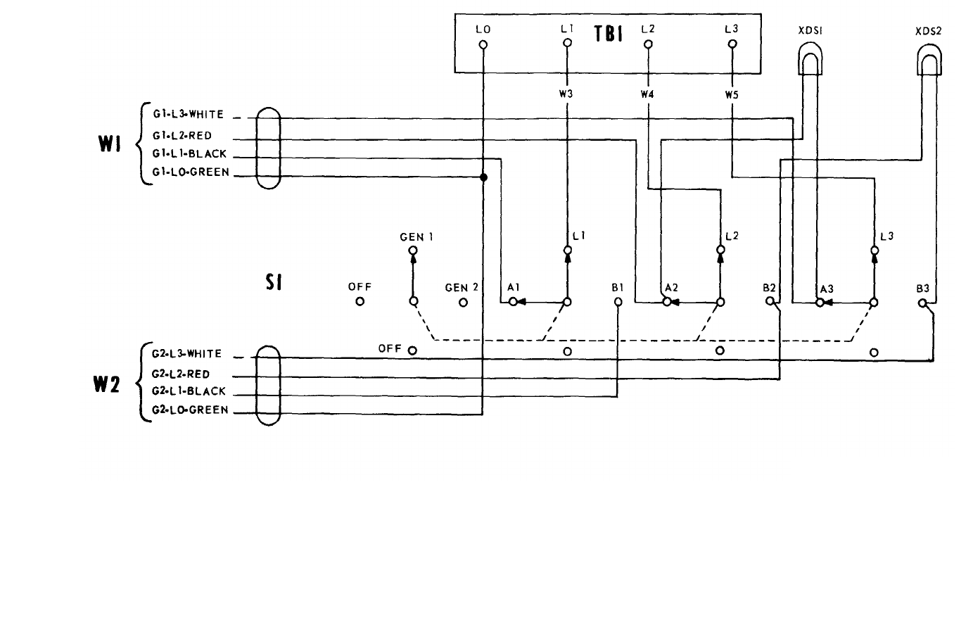
TM 5-6115-365-15
C 2,
Figure 19-6. Transfer switch wiring diagram..
ME 6115-365-15/19-6 C2
19-10
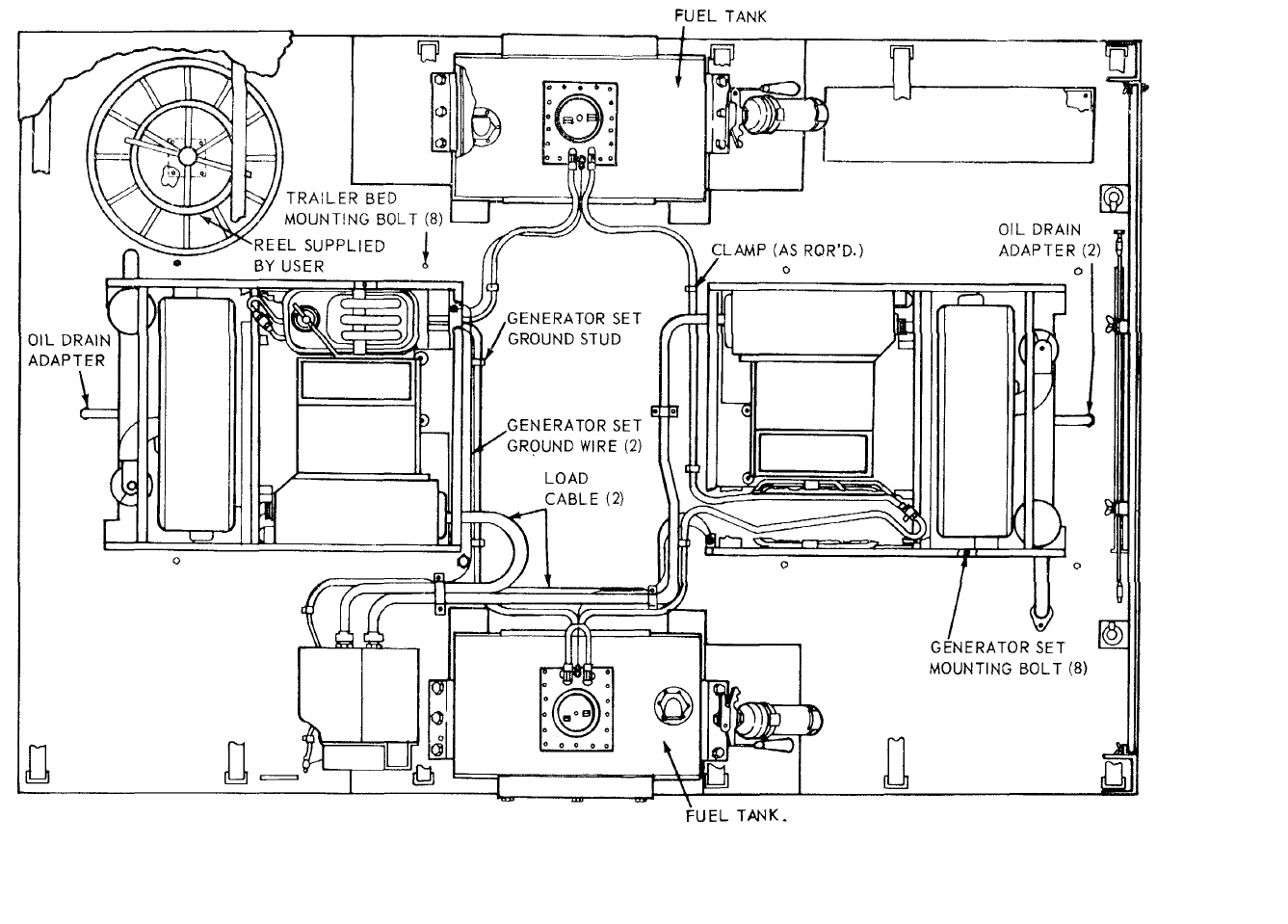
TM 5-6115-365-15
C 2,
Figure 19-7. PU-629/C overall component location diagram.
ME 6115-365-15/19-7 C2
19-11
TM 5-6115-365-15
C 2
19-14. Trailer Bed
a. Removal.
(1) Remove tarpaulin, roof bows, and leg prop
(para 19-10).
(2) Remove transfer switch from the trailer
(para 19-11).
(3) Remove the generator sets (para 19-12).
(4) Remove the 18 bolts (9 each fuel tank)
that secure the fuel tanks to the trailer and remove the
fuel tanks.
(5) Remove 8 bolts from the top surface of
the trailer bed and 12 bolts from the underside that
secure the trailer bed gussets to the trailer.
(6) Disconnect electrical leads from the trailer
lights. (7) Remove trailer bed from the trailer.
b. Cleaning, Inspection, and Repair.
(1) Clean trailer bed with approved cleaning
solvent and dry thoroughly.
(2) Inspect for broken welds, bends, dents,
and any damage that prevents proper assembly of the
unit. Weld cracks and breaks and straighten dents or
bends where possible. Replace a trailer bed that is
damaged beyond repair.
c. Installation.
(1) Install trailer bed on the trailer and secure
with 12 bolts on the underside and 8 on the top.
Connect wiring to trailer lights.
(2) Secure the two fuel tanks to the trailer with
18 bolts. (3) Install the generator sets (para 19-12).
(4) Install the transfer switch (para 19-11).
(5) Install the leg prop, roof bows, and
tarpaulin (para 19-10).
19-12

(1) (2) (3) (4) (5) (6) (7)
FEDERAL DESCRIPTION UNIT QTY 15-DAY ORGANIZATIONAL ILLUS-
SMR STOCK OF INC MAINTENANCE ALW RATION
CODE NUMBER USABLE MEAS IN (a) (b) (c) (d) (a) (b)
ON UNIT FIG ITEM
REF NUMBER & MFG CODE CODE 1-5 6-20 21-50 51-100 NO. NO.
TM 5-6115-365-15
C 2,
REPAIR PARTS FOR ORGANIZATIONAL MAINTENANCE
00001 GROUP 03 - FUEL SYSTEM
00002 0306 - TANKS, LINES, FITTINGS, HEADERS
X2 0CAP, FUEL TANK: tactical vehicle, fording EA 119-11 7
00003 MS35645-1 (96906)
00004 GROUP 15 - FRAME, TOWING ATTACHMENTS, AND DRAWBARS
00005 1501 - FRAME ASSEMBLY
X2 05340-999-6277 BRACKET ASSEMBLY EA 119-10 7
00006 13214E1214 (97403)
X2 0CLAMP, CABLE, DOUBLE: 1-5/16 height EA 119-9 45
00007 13212E3591-2 (97403)
X2 0CLAMP, CABLE, SINGLE EA 219-9 59
00008 13212E3612 (97403)
X2 02590-932-7298 CLAMP, GROUND ROD: 1.640 hole, sp EA 419-10 3
00009 13212E3617-1 (97403)
X2 0CLAMP, LOOP: double cable or tube EA 219-9 40
00010 MS21334-2 (96906)
X2 05340-914-2578 CLIP, SPRING EA 119-10 28
00011 13214E1213-1 (97403)
X2 0HOLDDOWN, REEL: 8.62 Ig EA 1 19-9 1
00012 13214E1426-3 (97403)
X2 07240-920-5327 HOLDER: fuel drum adapter EA 219-10 32
00013 13212E3553-1 (97403)
00 5310-934-9758 NUT, PLAIN, HEXAGON: machine screw, 10-24 EA 2****19-9 44
00014
05310-934-9758 NUT, PLAIN, HEXAGON: machine screw, 10-24 EA 6****19-9 58
00015
05310-088-1251 NUT, SELF-LOCKING, HEXAGON: 1/4-20 EA 1****19-10 31
00016
05310-088-1251 NUT, SELF-LOCKING, HEXAGON: 1/4-20 EA 2****19-9 48
00017
05310-088-1251 NUT, SELF-LOCKING, HEXAGON: 1/4-20 EA 2****19-9 62
00018
05310-088-1251 NUT, SELF-LOCKING, HEXAGON: 1/4 X 20 EA 4****19-10 10
00019
05310-088-1251 NUT, SELF-LOCKING, HEXAGON: 1/4-20 EA 8****19-10 6
00020
05310-984-3806 NUT, SELF-LOCKING, HEXAGON: 5/16-18 EA 4****19-10 35
00021
05310-964-3806 NUT, SELF-LOCKING, HEXAGON: 5/16-18 EA 6****19-9 32
00022
X2 0NUT, SELF-LOCKING, HEXAGON: 5/16-18 EA 619-9 25
00023 MS51922-9 (96906)
05310-984-3806 NUT, SELF-LOCKING, HEXAGON: 5/16-18 EA 12 ****19-9 29
00024
05305-071-2241 SCREW, CAP, HEXAGON HEAD: 1/4-20 X 1-1/4 EA 2****19-9 46
00025
05305-071-2241 SCREW, CAP, HEXAGON HEAD: 1/4-20 X 1-1/4 EA 4****19-9 60
00026
05305-068-0502 SCREW, CAP, HEXAGON HEAD: 1/4-20 X 3/4 Ig EA 1****19-10 29
00027
05305-068-0502 SCREW, CAP, HEXAGON HEAD: 1/4-20 X 3/4 Ig EA 2****19-10 8
00028
X2 0SCREW, CAP, HEXAGON HEAD: 5/16-18 X 3/4 EA 419-10 33
00029 MS90725-32 (96906)
X2 0SCREW, CAP, HEXAGON HEAD: 5/16-18 X 3/4 Ig EA 619-9 27
00030 MS90725-32 (96906)
X2 0SCREW, CAP, HEXAGON HEAD: 5/16-18 X 3/4 Ig EA 619-9 34
00031 MS90725-32 (96906)
19-13
(1) (2) (3) (4) (5) (6) (7)
FEDERAL DESCRIPTION UNIT QTY 15-DAY ORGANIZATIONAL ILLUS-
SMR STOCK OF INC MAINTENANCE ALW RATION
CODE NUMBER USABLE MEAS IN (a) (b) (c) (d) (a) (b)
ON UNIT FIG ITEM
REF NUMBER & MFG CODE CODE 1-5 6-20 21-50 51-100 NO. NO.
TM 5-6115-365-15
X2 0SCREW, CAP, HEXAGON HEAD: 5/16-18 X 3/4 Ig EA 12 19-9 31
00032 MS90725-32 (96906)
05305-958-5247 SCREW, MACHINE: flat head, 1/4-20 X 1 Ig EA 8****19-10 4
00033
05305-984-6212 SCREW, MACHINE, PAN HEAD: 10-24 X 3/4 Ig EA 2****19-9 41
00034
05305-984-6212 SCREW, MACHINE, PAN HEAD: 10-24 X 3/4 Ig EA 6****19-9 55
00035
X2 0WASHER, FLAT, ROUND EA 619-9 33
00036 MS27183-12 (96906)
05310-809-8546 WASHER, FLAT, ROUND: No. 10 nominal size EA 2****19-9 43
00037
05310-809-8546 WASHER, FLAT, ROUND: No. 10 EA 6****19-9 57
00038
X2 0WASHER, FLAT, ROUND: 1/4 nominal size EA 219-10 30
00039 MS27183-11 (96906)
X2 0WASHER, FLAT, ROUND: 1/4 nominal size EA 419-10 9
00040 MS27183-11 (96906)
X2 0WASHER, FLAT, ROUND: 1/4 nominal size EA 819-10 5
00041 MS27183-11 (96906)
X2 0WASHER, FLAT, ROUND: 1/4-20 nominal size EA 419-9 47
00042 MS27183-11 (96906)
X2 0WASHER, FLAT, ROUND: 1/4-20 nominal size EA 819-9 61
00043 MS27183-11 (96906)
05310-081-4219 WASHER, FLAT, ROUND: 5/16 nominal size EA 6****19-9 26
00044
05310-081-4219 WASHER. FLAT, ROUND: 5/16 nominal size EA 8****19-10 34
00045
05310-081-4219 WASHER, FLAT, ROUND. 5/16 nominal size EA 12 ****19-9 30
00046
05310-045-3296 WASHER, LOCK, HELICAL No. 10 nominal size EA 6****19-9 56
00047
05310-045-3296 WASHER, LOCK: spring helical, No. 10 EA 2****19-9 42
00048
00049 GROUP 22 - BODY, CHASSIS OR HULL, AND ACCESSORY ITEMS
2201 - CANVAS, RUBBER, OR PLASTIC ITEMS
P02540-924-8478 BOW, TRAILER TARPAULIN EA 4******
13215E3597-1 (97403)
P02540-926-1003 BOW, TRAILER TARPAULIN EA 2******
13212E3597-2 (97403)
P0 R TARPAULIN EA 1******
13216E7434 (97403)
X2 FBUCKLE EA 18
MS51920 (96906)
X2 FCHAPE ASSEMBLY EA 12
13214E1392 (97403)
X2 FHOOK TEE EA 22
13214E1497 (97403)
X2 FRING, TEE EA 14
MS51925 (96906)
X2 FTIP END EA 24
MS51926 (96906)
00050 2202 - ACCESSORY ITEMS
X2 0ACCESSORY BOX EA 119-9 8
00051 13205E4949 (97403)
PC2910-066-1235 ADAPTER ASSEMBLY, FUEL DRUM EA 2****19-10 1
00052 13211E7541 (97403)
PC5120-265-7462 HAMMER HAND. 8 lb EA 1****19-10 27
00053 GGGH86TYPEX (81348)
05310-088-1251 NUT, SELF-LOCKING, HEXAGON: 1/4-20 EA 4****19-9 11
00054
19-14 Change 8

(1) (2) (3) (4) (5) (6) (7)
FEDERAL DESCRIPTION UNIT QTY 15-DAY ORGANIZATIONAL ILLUS-
SMR STOCK OF INC MAINTENANCE ALW RATION
CODE NUMBER USABLE MEAS IN (a) (b) (c) (d) (a) (b)
ON UNIT FIG ITEM
REF NUMBER & MFG CODE CODE 1-5 6-20 21-50 51-100 NO. NO.
TM 5-6115-365-15
PC5975-878-3791 ROD, GROUND ASSEMBLY EA 2****19-10 2
00055 MILR11461TYPE (81349)
05305-068-0502 SCREW, CAP, HEXAGON HEAD: 1/4-20 X 3/4 Ig EA 4****19-9 9
00056
X2 0WASHER, FLAT, ROUND: 1/4 nominal size EA 419-9 10
00057 MS27183-11 (96906)
M0WIRE, ELECTRICAL: No. 6 AWG, 10 ft FT 19-9 53
00058 MANUFACTURE FROM:
P06145-395-8755 WIRE, ELECTRICAL: No. 6 AWG FT SEE GRP 9501
00059 QQW343TYPERB (81348)
00060 2210 - DATA PLATES
X2 0PLATE, IDENTIFICATION: ground terminal EA 119-9 39
00061 13205E4918 (97403)
X2 0PLATE, IDENTIFICATION: PU-6290/6 EA 119-9 17
00062 13205E4916-22 (97403)
Change 8 19-14.1/(19-14.2 blank)
(1) (2) (3) (4) (5) (6) (7)
FEDERAL DESCRIPTION UNIT QTY 15-DAY ORGANIZATIONAL ILLUS-
SMR STOCK OF INC MAINTENANCE ALW RATION
CODE NUMBER USABLE MEAS IN (a) (b) (c) (d) (a) (b)
ON UNIT FIG ITEM
REF NUMBER & MFG CODE CODE 1-5 6-20 21-50 51-100 NO. NO.
TM 5-6115-365-15
C 2,
00063 GROUP 29 - AUXILIARY GENERATOR AND ENGINE AND CONTROLS
00064 2941 - EXHAUST AND TAIL PIPES
05310-088-1251 NUT, SELF-LOCKING, HEXAGON:1/4-10 EA 4****19-9 51
00065
05310-088-1251 NUT, SELF-LOCKING, HEXAGON:1/4-20 EA 2****19-9 16
00066
05305-225-3839 SCREW, CAP, HEXAGON HEAD:1/4-20 x I 19 EA 2****19-9 14
00067
05305-068-0502 SCREW, CAP, HEXAGON HEAD:1/4-20 x 3/4 19 EA 4****19-9 50
00068
X2 0WASHER, FLAT, ROUND: 1/4 nominal size EA 419-9 15
00069 MS27183-11 (96906)
X2 0WASHER, FLAT, ROUND: 1/4 nominal size EA 8
00070 MS27183-11 (96906)
00071 GROUP 40 - ELECTRIC MOTORS AND GENERATORS
00072 4000 - GENERATOR ASSEMBLY
X2 0NUT, SELF-LOCKING, HEAD EA 819-9 19
00073 MS51922-33 (96906)
05305-782-9494 SCREW, CAP, HEXAGON HEAD:1/2-13 x 1-3/4 EA 8****19-9 21
00074
X2 0WASHER, BEVELED: 1/2 nominal bolt size EA 819-9 22
00075 13206E4482-2 (97403)
X2 0WASHER, FLAT, ROUND: 1/2 nominal size EA 819-9 20
00076 MS27183-18 (96906)
00077 GROUP 42 - ELECTRICAL EQUIPMENT
00078 4206 - THERMOSTATIC, AUTOMATIC AND MANUAL
CONTROL DEVICES
05310-087-4652 NUT, SELF-LOCKING, HEXAGON:3/8-16 EA 4****19-9 38
00079
05305-269-3211 SCREW, CAP, HEXAGON HEAD:3/8-16 x 1 lg EA 4****19-9 36
00080
05310-809-4061 WASHER, FLAT, ROUND: 3/8 nominal size EA 8****19-9 37
00081
00082 4216 - MISCELLANEOUS WIRING AND FITTINGS
X2 0CLAMP, LOOP: double cable or tube EA 219-10 13
00083 MS21334-30 (96906)
05310-543-4717 NUT, PLAIN, WING: brass, 3/8-16 EA 119-10 18
00084
X2 0NUT, PLAIN, HEXAGON: jam, 3/8-16 EA 119-10 24
00085 MS16203-39 (96906)
X2 0NUT, PLAIN, HEXAGON: jam, 3/8-16 EA 319-10 22
00086 MS16203-39 (96906)
05310-934-9758 NUT, PLAIN, HEXAGON:machine screw, No. 10-24 EA 2****19-10 14
00087
05940-688-6010 TERMINAL, LUG: Type I, Class I, No. 6-3/8 EA 4****19-10 23
00088
X2 0TERMINAL, LUG: No. b wire, No. 10 stud EA 219-10 11
00089 MS20659-130 (96906)
X2 0SCREW, CAP, HEXAGON HEAD:3/8-16 x 3/4 EA 119-10 26
00090 MS35309-358 (96906)
05305-984-6212 SCREW, MACHINE: pan head, No. 10-24 x 3/4 Ig EA 2****19-10 17
00091
X2 0STUD GROUNDING EA 119-10 21
00092 13214E1223 (97403)
X2 0WASHER, FLAT, ELECTRIC:3/8 nominal size EA 419-10 19
00093 AN961-616T (88044)
05310-809-8546 WASHER, FLAT, ROUND: No. 10 nominal size EA 2****19-10 15
00094
19-15

(1) (2) (3) (4) (5) (6) (7)
FEDERAL DESCRIPTION UNIT QTY 15-DAY ORGANIZATIONAL ILLUS-
SMR STOCK OF INC MAINTENANCE ALW RATION
CODE NUMBER USABLE MEAS IN (a) (b) (c) (d) (a) (b)
ON UNIT FIG ITEM
REF NUMBER & MFG CODE CODE 1-5 6-20 21-50 51-100 NO. NO.
TM 5-6115-365-15
C 2,
05310-913-9776 WASHER, LOCK: flat, external tooth, 3/8 EA 1****19-10 25
00095
05310-913-9776 WASHER, LOCK: flat, external tooth, 3/8 EA 2****19-10 20
00096
05310-045-3296 WASHER, LOCK: spring helical, No. 10 EA 2****19-10 16
00097
00098 GROUP 76 - FIRE FIGHTING EQUIPMENT COMPONENTS
00099 7638 - PORTABLE FIRE FIGHTING EQUIPMENT
PC4210-555-8837 EXTINGUISHER, FIRE EA 2****19-9 4
00100 MILE52031 (81349)
05310-088-1251 NUT, SELF-LOCKING, HEXAGON:1/4-20 EA 8****19-9 7
00101
05305-068-0502 SCREW, CAP, HEXAGON HEAD:1/4-20 x 3/4 19 EA 8****19-9 5
00102
X2 05310-809-4058 WASHER, FLAT, ROUND: 1/4 nominal size EA 16 19-9 6
00103 MS27183-11 (96906)
00104 GROUP 95 - GENERAL USE STANDARDIZED PARTS
00105 9501 - HARDWARE SUPPLIES AND BULK MATERIEL, COMMON
P06145-395-8755 WIRE, ELECTRICAL: No. 6 AWG FT AR 19-10 12
00106 QQW343TYPERB (81348)
19-16
(1) (2) (3) (4) (5) (6) (7) (8) (9) (10)
DESCRIPTION 1-YR
DEPOT
QTY
30-DAY DS MAINT
30-DAY GS MAINT
ALW
PER MAINT
ALW ILLUS-
TRATION
FEDERAL USABLE UNIT INC ALLOWANCE ALLOWANCE 100 PER (a) (b)
SMR
CODE STOCK
NUMBER
ON
REF NUMBER & MFR CODE CODE OF
MEAS
IN
UNIT (a)
1-20 (b)
21-50 (c)
51-100 (a)
1-20 (b)
21-50 (c)
51-100
EQUIP
CNTGCY
100
EQUIP FIG.
NO. ITEM
NO.
TM 5-6115-365-15
C 2,
PART II
REPAIR PARTS FOR DS, Gs,
AND DUCT MAINTENANCE
00001 GROUP 03 - FUEL SYSTEM
00002 0306 - TANK, LINES, FITTINGS, HEADERS
X2 FBRACKET, FUEL TANK EA 219-9 24
00003 13216E7416 (97403)
X2 FBRACKET, FUEL TANK EA 419-9 28
00004 13216E7423 (97403)
X2 FBRACKET, FUEL TANK EA 219-9 35
00005 13216E7463 (97403)
X2 0CAP, FUEL TANK: tactical vehicle,
00006 fording EA 119-11 7
MS35645-1 (96906)
X2 FELBOW: 90 deg, flared, 5/16 x 1/2-20 EA 219-11 1
00007 SAEJ514 (81343)
X2 FFILLER, NECK EA 119-11 10
00008 13216E7574 (97403)
X2 PFILTER, FUEL: 15.75 Ig EA 219-11 12
00009 13216E7570-2 (97403)
X2 FGAGE LIQUID LEVEL: 21.25 1g EA 119-11 4
00010 13216E7459-3 (97403)
X2 FGASKET EA 119-11 6
00011 13216E7460 (97403)
X2 FGASKET EA 119-11 11
00012 13216E7575 (97403)
X2 FMOUNT GAGE EA 119-11 5
00013 13216E7458 (97403)
X2 FPLUG, SQUARE HEAD: pipe thread, steel,
00014 1/4 NPT EA 119-11 13
MS20913-2S (96906)
X2 FSCREW, MACHINE: pan head, No. 10-32 x
00015 5/8 in. lg EA 619-11 3
MS35207-264 (96906)
X2 FSCREW, MACHINE: pan head, No. 10-32 x
00016 5/8 EA 18 19-11 8
MS35207-264 (96906)
X2 FTANK, FUEL EA 119-11 14
00017 13216E7573 (97403)
X2 F WASHER, LOCK: sprig helical, No. 10 EA 6 19-11 2
00018 MS35338-43 (96906)
12 FWASHER, LOCK: spring helical, No. 10 EA 18 19-11 9
00019 MS35338-43 (96906)
00020 GROUP 15 - FRAME, TOWING ATTACHMENTS,
AND DRAWBARS
00021 1501 - FRAME ASSEMBLY
X2 05340-999-6277 BRACKET ASSEMBLY EA 119-10 7
00022 13214E1214 (97403)
X2 0CLAMP, CABLE, DOUBLE: 1-5/16 height EA 119-9 45
00023 13212E3591-2 (97403)
X2 0CLAMP, CABLE SINGLE EA 219-9 59
00024 13212E3612 (97403)
19-17
(1) (2) (3) (4) (5) (6) (7) (8) (9) (10)
DESCRIPTION 1-YR
DEPOT
QTY 30-DAY DS MAINT 30-DAY GS MAINT ALW
PER
MAINT
ALW ILLUS-
TRATION
FEDERAL USABLE
UNIT
INC ALLOWANCE ALLOWANCE 100 PER (a) (b)
SMR
CODE STOCK
NUMBER
ON
REF NUMBER & MFR CODE CODE OF
MEAS IN
UNIT (a)
1-20 (b)
21-50 (c)
51-100 (a)
1-20 (b)
21-50 (c)
51-100
EQUIP
CNTGCY 100
EQUIP
FIG.
NO.
ITEM
NO.
TM 5-6115-365-15
C 2,
X2 02590-932-7298 CLAMP, GROUND ROD: 1.640 hole, sp EA 419-10 3
00025 13212E3617-1 (97403)
X2 0CLAMP, LOOP: double cable or tube EA 219-9 40
00026 MS21334-2 (96906)
X2 FCLAMP, LOOP: Type If, Class A and B EA 619-9 54
00027 MS21104D10 (96906)
X2 05340-914-2578 CLIP, SPRING EA 119-10 28
00028 13214E1213-1 (97403)
X2 0HOLDDOWN, REEL: 8.62 lg EA 119-9 1
00029 13214E1426-3 (97403)
X2 07240-920-5327 HOLDER: fuel drum adapter BA 219-10 32
00J30 13212E3553-1 (97403)
05310-934-9758 NUT, PLAIN, HEXAGON: machine screw, EA 2****** *19-9 44
00031 10-24
05310-934-9758 NUT, PLAIN, HEXAGON: machine screw,
00032 10-24 EA 6******* *19-9 58
05310-088-1251 NUT, SELF-LOCKING, HEXAGON: 1/4-20 EA 1******* *19-10 31
00033
05310-088-1251 NUT, SELF-LOCKING, HEXAGON: 1/4-20 EA 2******* *19-9 48
00034
05310-088-1251 NUT, SELF, LOCKING, HEXAGON: 1/4-20 EA 2******* *19-9 62
00035
05310-088-1251 NUT, SELF-LOCKING, HEXAGON: 1/4 x 20 EA 4****a a * * 19-10 10
00036
05310-088-1251 NUT, SELF-LOCKING, HEXAGON: 1/4-20 EA 8******* *19-10 6
00037
05310-984-3806 NUT, SELF-LOCKING, HEXAGON: 5/16-18 EA 4******* *19-10 35
00038
05310-984-3806 NUT, SELF- LOCKING, HEXAGON: 5,/16-18 EA 6******* *19-9 32
00039
X2 0NUT, SELF-LOCKING, HEXAGON: 5/16-18 EA 619-9 25
00040 MS51922-9 (96906)
05310-984-3806 NUT, SELF- LOCKING, HEXAGON: 5/16-18 EA 12 ******* *L9-9 29
00041
05305-071-2241 SCREW, CAP, HEXAGON HEAD: 1/4-20 x 1-1/4 EA 2******* *L9-9 46
00042
05305-071-2241 SCREW, CAP, HEXAGON HEAD: 1/4-20 x 1.1/4 EA 4******* *19-9 60
00o43
05305-068-0502 SCREW, CAP, HEXAGON HEAD: 1/4-20 x 3/4
00044 lg EA 1******* *19-10 29
05305-O68-0502 SCREW, CAP, HEXAGON HEAD: 1/4-20 x 3/4
00045 lg EA 2******* *19-10 8
X2 0SCREW, CAP, HEXAGON HEAD: 5/16-18 x 3/4b EA 419-10 33
00046 MS90725-32 (96906)
X2 0SCREW, CAP, HEXAGON READ: 5/16-18 x 3/4
00047 lg EA 619-9 27
MS90725-32 (96906)
X2 0SCREW, CAP, HEXAGON HEAD: 5/16-18 x 3/4
00048 lg EA 619-9 34
MS90725-32 (96906)
X2 0SCREW, CAP, HEXAGON HEAD: 5/16-18 x 3/4
00049 Ig EA 12 19-9 31
MS90725-32 (96906)
05305-958-5247 SCREW, MACHINE: flat head, 1/4-20 x 1
00050 lg EA 8******* *19-10 4
05305-984-6212 SCREW, MACHINE, PAN HEAD: 10-24 x 3/4
00051 Ig EA 2******* *19-9 41
05305-984-6212 SCREW, MACHINE, PAN HEAD: 10-24 x 3/4 EA 6******* *19-9 55
00052 lg
19-18

(1) (2) (3) (4) (5) (6) (7) (8) (9) (10)
DESCRIPTION 1-YR
DEPOT
QTY 30-DAY DS MAINT 30-DAY GS MAINT ALW
PER MAINT
ALW ILLUS-
TRATION
FEDERAL USABLE UNIT INC ALLOWANCE ALLOWANCE 100 PER (a) (b)
SMR
CODE STOCK
NUMBER
ON
REF NUMBER & MFR CODE CODE OF
MEAS IN
UNIT (a)
1-20 (b)
21-50 (c)
51-100 (a)
1-20 (b)
21-50 (c)
51-100
EQUIP
CNTGCY 100
EQUIP FIG.
NO. ITE
M
NO.
TM 5-6115-365-15
C2
X2 OWASHER, FLAT, ROUND EA 619-9 33
00053 MS27183-12 (96906)
O5310-809-8546 WASHER, FLAT, ROUND: No. 10 nominal EA 2******* *19-9 43
00054 size
O5310-809-8546 WASHER, FLAT, ROUND: No. 10 nominal EA 6******* *19-9 57
00055 size
X2 OWASHER, FLAT, ROUND: 1/4 nominal size EA 219-10 30
00056 MS27183-11 (96906)
X2 OWASHER, FLAT, ROUND: 1/4 nominal size EA 419-10 9
00057 MS27183-11 (96906)
X2 OWASHER, FLAT, ROUND: 1/4 nominal size EA 819-10 5
00058 MS27183-11 (96906)
X2 OWASHER, FLAT, ROUND: 1/4-20 nominal size EA 419-9 47
00059 MS27183-11 (96906)
X2 OWASHER, FLAT, ROUND: 1/4-20 nominal size EA 819-9 61
00060 MS27183-11 (96906)
O5310-081-4219 WASHER, FLAT, ROUND: 5/16 nominal size EA 6******* *19-9 26
00061
O5310-081-4219 WASHER, FLAT, ROUND: 5/16 nominal size EA 8******* *19-10 34
00062
O5310-081-4219 WASHER, FLAT, ROUND: 5/16 nominal size EA 12 ******* *19-9 30
00063
O5310-045-3296 WASHER, LOCK, HELICAL: No. 10 nominal
00064 size EA 6******* *19-9 56
O5310-045-3296 WASHER, LOCK:spring helical, No. 10 EA 2******* *19-9 42
00065
00066 GROUP 18 - BODY, CAB, HOOD AND HULL
00067 1810 - CARGO BODY
X2 DR 2330-141-8052 TRAILER, FLAT BED EA 119-9 12
00068 13205E5157 (97403)
00069 GROUP 22 - BODY, CHASSIS OR HULL,
AND ACCESSORY ITEMS
00070 2202 - ACCESSORY ITEMS
X2 OACCESSORY, BOX EA 119-9 8
00071 13205E4949 (97403)
PC2910-066-1235 ADAPTER ASSEMBLY, FUEL DRUM EA 2* * 2* * 2 10 10 19-10 1
00072 13211E7541 (97403)
PC5120-265-7462 HAMMER HAND: 8 lb EA 1* * 2* * 2 10 10 19-10 27
00073 GGGH86TYPEX (81348)
X2 FHOSE ASSEMBLY: 5/16 od x 112 EA 219-9 3
00074 MS28741-5-1120 (96906)
X2 FHOSE ASSEMBLY: 5/16 od x 96 in. lg EA 219-9 2
00075 MS28741-5-0960 (96906)
O5310-088-1251 NUT, SELF-LOCKING, HEXAGON: 1/4-20 EA 4******* *19-9 11
00076
PC5975-878-3791 ROD, GROUND ASSEMBLY EA 2* * 2* * 2 10 10 19-10 2
00077 MILR11461TYPE (81349)
O5305-068-0502 SCREW, CAP, HEXAGON HEAD: 1/4-20 x 3/4
00078 lg EA 4******* *19-9 9
X2 OWASHER, FLAT, ROUND: 1/4 nominal size EA 419-9 10
00079 MS27183-11 (96906)
MOWIRE, ELECTRICAL: No. 6 AWG, 10 ft FT 19-9 53
00080 MANUFACTURE FROM:
PO6145-395-8755 WIRE, ELECTRICAL: No. 6 AWG FT SEE GRP 9501
00081 QQW343TYPERB(81348)
19-19
(1) (2) (3) (4) (5) (6) (7) (8) (9) (10)
DESCRIPTION 1-YR
DEPOT
QTY 30-DAY DS MAINT 30-DAY GS MAINT ALW
PER MAINT
ALW ILLUS-
TRATION
FEDERAL USABLE UNIT INC ALLOWANCE ALLOWANCE 100 PER (a) (b)
SMR
CODE STOCK
NUMBER
ON
REF NUMBER & MFR CODE CODE OF
MEAS IN
UNIT (a)
1-20 (b)
21-50 (c)
51-100 (a)
1-20 (b)
21-50 (c)
51-100
EQUIP
CNTGCY 100
EQUIP FIG.
NO. ITEM
NO.
TM 5-6115-365-15
C2
00082 2210 - DATA PLATES
X2 OPLATE, IDENTIFICATION: ground terminal EA 119-9 39
00083 13205E4918 (97403)
X2 OPLATE, IDENTIFICATION: PU-6290/6 EA 119-9 17
00084 13205E4916-22 (97403)
X2 FPLATE, INFORMATION WIRE DIAGRAM EA 1
00085 13212E3587 (97403)
00086 GROUP 29 - AUXILIARY GENERATOR AND
ENGINE AND CONTROLS
00087 2935 - ENGINE FUEL TANK
X2 FTANK ASSEMBLY, FUEL EA 219-9 23
00088 13216E7417 (97403)
00089 2941 - EXHAUST AND TAIL PIPES
P2 F6115-947-3331 EXHAUST TUBE EA 1******2 4 19-9 49
00090 13214E1486 (97403)
P P 6115-947-3335 EXHAUST TUBE EA 1******2 4 19-9 13
00091 13214E1487 (97403)
X2 FNUT, PLATE, REEL HOLDDOWN EA 119-9 52
00092 13205E4948 (97403)
O5310-088-1251 NUT, SELF-LOCKING, HEXAGON: 1/4-10 EA 4******* *19-9 51
00093
O5310-088-1251 NUT, SELF-LOCKING, HEXAGON: 1/4-20 EA 2******* *19-9 16
00094
O5305-225-3839 SCREW, CAP, HEXAGON HEAD: 1/4-20 x lg EA 2******* *19-9 14
00095
O5305-068-0502 SCREW, CAP, HEXAGON READ: 1/4-20 x 3/4
00096 lg EA 4******* *19-9 50
X2 OWASHER, FLAT, ROUND: 1/4 nominal size EA 419-9 15
00097 MS27183-11 (96906)
X2 OWASHER, FIAT, ROUND: 1/4 nominal size EA 8
0098 MS27183-11 (96906)
00099 GROUP 40 - ELECTRIC MOTORS AND GENERATORS
00100 4000 - GENERATOR ASSEMBLY
X2 FR 6115-017-8240 GENERATOR SET: SF-5.0-MD EA 219-9 18
00101 MILG52279TYPE1 (81349)
X2 ONUT, SELF-LOCKING, READ EA 819-9 19
00102 MS51922-33 (96906)
O5305-782-9494 SCREW, CAP, HEXAGON HEAD: 1/2-13 x 1-3/4 EA 8******* *19-9 21
00103
X2 OWASHER, BEVELED:1/2 nominal bolt size EA 819-9 22
00104 13206E4482-2 (97403)
X2 OWASHER, FLAT, ROUND: 1/2 nominal size EA 819-9 20
00105 MS27183-18 (96906)
00106 GROUP 42 - ELECTRICAL EQUIPMENT
00107 4206 - THERMOSTATIC, AUTOMATIC AND
MANUAL CONTROL DEVICES
X2 FBOX, DISTRIBUTION EA 119-8 17
00108 13212E3602 (97403)
X2 FCABLE EA 119-8 15
00109 13212E3607 (97403)
X2 FCABLE EA 119-8 16
00110 13212E3608 (97403)
X2 FCOVER EA 119-8 32
00111 13212E3603 (97403)
19-20

(1) (2) (3) (4) (5) (6) (7) (8) (9) (10)
DESCRIPTION 1-YR
DEPOT
QTY 30-DAY DS MAINT 30-DAY GS MAINT ALW
PER MAINT
ALW ILLUS-
TRATION
FEDERAL USABLE UNIT INC ALLOWANCE ALLOWANCE 100 PER (a) (b)
SMR
CODE STOCK
NUMBER
ON
REF NUMBER & MFR CODE CODE OF
MEAS IN
UNIT (a)
1-20 (b)
21-50 (c)
51-100 (a)
1-20 (b)
21-50 (c)
51-100
EQUIP
CNTGCY 100
EQUIP FIG.
NO. ITEM
NO.
TM 5-6115-365-15
C2
X2 FGASKET EA 119-8 18
00112 13212E3610 (97403)
X2 FLEAD, ELECTRICAL EA 119-8 12
`00113 13212E3609-3 (97403)
X2 FLEAD, ELECTRICAL: No. W3 EA 119-8 10
00114 13212E3609-1 (97403)
X2 FLEAD, ELECTRICAL: No. W4 EA 119-8 11
00115 13212E3609-2 (97403)
2FLIGHT AND WIRE: 12 in. Ig EA 219-8 1
0116 13212E3581-1 (97403)
X2 FNUT, PLAIN, HEXAGON: brass, 1/4-28 EA 919-8 28
00117 MS51970-1 (96906)
X2 FNUT, PLAIN, HEXAGON: Jam, 1/4-20 EA 819-8 24
00118 MS16203-37 (96906)
X2 FNUT, PLAIN, HEXAGON: machine screw, No.
00119 10-24 EA 619-8 27
MS35649-202 (96906)
X2 FNUT, SELF-LOCKING, HEXAGON: 3/8-16 EA 419-8 8
00120 MS51922-17 (96906)
O5310-087-4652 NUT, SELF-LOCKING, HEXAGON: 3/8-16 EA 4******* *19-9 38
00121
X2 FPACKING, PREFORMED "O" RING EA 119-8 31
00122 MS28775-111 (96906)
X2 FPACKING, PREFORMED "O" RING EA 419-8 3
00123 MS28775-013 (96906)
X2 FPACKING, PREFORMED “O" RING EA 219-8 13
00124 M28775-132 (96906)
X2 FPLATE INFORMATION WIRING DIAGRAM EA 1SEE GRP 2210
00125 13212E3587 (97403)
O5305-269-3211 SCREW, CAP, HEXAGON HEAD: 3/8-16 x 1 lg EA 4******* *19-9 36
00126
X2 FSCREW, MACHINE: pan head, No. 10-24 x 1
00127 Ig EA 619-8 21
MS35206-267 (96906)
X2 FSCREW, MACHINE: pan heed, No. 10-32 x
00128 1/2 EA 16 19-8 4
MS35207-263 (96906)
X2 FSCREW, MACHINE: pan head, 1/4-28 x 7/16 EA 919-8 9
00129 MS35215-68 (96906)
X2 FSCREW, MACHINE: pan head, 3/8-16 x 2 lg EA 419-8 2
00130 MS35206-315 (96906)
X2 FSTUFFING TUBE EA 219-8 14
00131 13212E3582-20 (97403)
P2 F5930-829-3243 SWITCH, ROTARY: 60 amp EA 1******2 2 19-8 30
00132 13205E5023 (97403)
X2 FTERMINAL BOARD EA 119-8 19
00133 13212E3606 (97403)
X2 FTERMINAL LOAD: 3-3/16 in. 1g EA 419-8 20
00134 13208E5820-6 (97403)
X2 FTERMINAL, LUG: size 22-18 stud, 1/4 In.
00135 lg EA 4
MS25036-150 (96906)
X2 FWASHER, FLAT, ROUND: No. 10 nominal
00136 size EA 12 19-8 22
MS27183-8 (96906)
19-21
(1) (2) (3) (4) (5) (6) (7) (8) (9) (10)
DESCRIPTION 1-YR
DEPOT
QTY 30-DAY DS MAINT 30-DAY GS MAINT ALW
PER MAINT
ALW ILLUS-
TRATION
FEDERAL USABLE UNIT INC ALLOWANCE ALLOWANCE 100 PER (a) (b)
SMR
CODE STOCK
NUMBER
ON
REF NUMBER & MFR CODE CODE OF
MEAS IN
UNIT (a)
1-20 (b)
21-50 (c)
51-100 (a)
1-20 (b)
21-50 (c)
51-100
EQUIP
CNTGCY 100
EQUIP FIG.
NO. ITEM
NO.
TM 5-6115-365-15
C2
X2 FWASHER, FLAT, ROUND: No. 10 nominal size EA 16 19-8 6
00137 MS27183-8 (96906)
O5310-809-4061 WASHER, FLAT, ROUND: 3/8 nominal size EA 8******* *19-9 37
00138
X2 FWASHER, FLAT, ROUND: 3/8 nominal size EA 819-8 7
00139 MS27183-14 (96906)
X2 FWASHER, LOCK: flat, external tooth, 1/4
00140 lg EA 919-8 29
MS35335-89 (96906)
X2 FWASHER, LOCK: flat, internal tooth, 1/4
00141 Ig EA 419-8 23
MS35333-108 (96906)
X2 FWASHER, LOCK: spring helical, No. 10 EA 619-8 26
00142 MS35338-43 (96906)
X2 FWASHER, LOCK: spring helical, No. 10 EA 16 19-8 5
00143 MS535338-43 (96906)
X2 FWASHER, LOCK: spring helical, 1/4 lg EA 819-8 25
00144 MS35338-101 (96906)
00145 4216 - MISCELLANEOUS WIRING AND FITTING
X2 OCLAMP, LOOP: double cable or tube EA 219-10 13
00146 MS21334-30 (96906)
O5310-543-4717 NUT, PLAIN, WING: brass, 3/8-16 EA 1******* *19-10 18
00147
X2 ONUT, PLAIN, HEXAGON: Jam, 3/8-16 EA 119-10 24
00148 MS16203-39 (96906)
X2 ONUT, PLAIN, HEXAGON: Jam, 3/8-16 EA 319-10 22
00149 MSS16203-39 (96906)
O5310-934-9758 NUT, PLAIN, HEXAGON:machine screw, No.
00150 10-24 EA 2******* *19-10 14
O5940-688-6010 TERMINAL, LUG:Type I, Class 1, No.
00151 6-3/8 EA 4******* *19-10 23
X2 OTERMINAL, LUG: No. 6 wire, No. 10 stud EA 219-10 11
00152 MS20659-130 (96906)
X2 OSCREW, CAP, HEXAGON HEAD: 3/8-16 x 3/4 EA 119-10 26
00153 MS35309-358 (96906)
O5305-984-6212 SCREW, MACHINE: pan head, No. 10-24 x 3/4
00154 lg EA 2******* *19-10 17
X2 OSTUD GROUNDING EA 119-10 21
00155 13214E1223 (97403)
X2 OWASHER, FIAT, ELECTRIC: 3/8 nominal size EA 419-10 19
00156 AN961-616T (88044)
O5310-809-8546 WASHER, FLAT, ROUND: No. 10 nominal size EA 2******* *19-10 15
00157
O5310-913-9776 WASHER, LOCK:flat, external tooth, 3/8 EA 1******* *19-10 25
00158
O5310-913-9776 WASHER, LOCK:flat, external tooth, 3/8 EA 2******* *19-10 20
00159
O5310-045-3296 WASHER, LOCK:spring helical, No. 10 EA 2******* *19-10 16
00160
00161 GROUP 76 - FIRE FIGHTING
EQUIPMENT COMPONENTS
00162 7638 - PORTABLE FIRE
FIGHTING EQUIPMENT
PC4210-555-8837 EXTINGUISHER, FIRE EA 2* * 2* * 2 10 10 19-9 4
00163 MILE52031 (81349)
O5310-088-1251 NUT, SELF-LOCKING, HEXAGON: 1/4-20 EA 8******* *19-9 7
00164
19-22
(1) (2) (3) (4) (5) (6) (7) (8) (9) (10)
DESCRIPTION 1-YR
DEPOT
QTY 30-DAY DS MAINT 30-DAY GS MAINT ALW
PER MAINT
ALW ILLUS-
TRATION
FEDERAL USABLE UNIT INC ALLOWANCE ALLOWANCE 100 PER (a) (b)
SMR
CODE STOCK
NUMBER
ON
REF NUMBER & MFR CODE CODE OF
MEAS IN
UNIT (a)
1-20 (b)
21-50 (c)
51-100 (a)
1-20 (b)
21-50 (c)
51-100
EQUIP
CNTGCY 100
EQUIP FIG.
NO. ITE
M
NO.
TM 5-6115-365-15
C2
O5305-068-0502 SCREW, CAP, HEXAGON HEAD: 1/4-20 x 3/4
00165 Ig EA 8******* *19-9 5
X2 O5310-809-3078 WASHER, FLAT, ROUND: 1/4 nominal size EA 16 19-9 6
00166 MS27183-11 (96906)
00167 GROUP 95 - GENERAL USE
STANDARDIZED PARTS
00168 9501 - HARDWARE SUPPLIES AND
BULK MATERIEL, COMMON
X2 O6145-395-8755 WIRE, ELECTRICAL: No. 6 AWG FT AR 19-10 12
00169 QQW343TYPERB (81348)
PO4730-00-199-1493 NIPPLE: PIPE, STANDARD STEEL 1/2 NPT X 2 L EA 219-12 1
STL ZN CTD LONG
MS51953-78 (96906)
PO4730-00-908-3193 CLAMP, HOSE: LOW PRESSURE TYPE "F" HOSE DIA EA 219-12 2
RANGE 1-1/16 X 2 CRES
MS35842-12 (96906)
PO4720-01-073-7435 HOSE FUEL AND OIL EA 219-12 3
13218E0153-20 (97403)
PO4730-00-804-0544 UNION FLARED TUBE: 3/8 BULKHEAD AND UNIVERSAL, EA 219-12 4
PRECISION TYPE 5/8 OD TUBE X 7/8-14 UNF-3A STL
MS24393-16 (96906)
PO5310-00-754-2005 WASHER, LOCK-SPRING, HELICAL: REGULAR (MEDIUM) EA 219-12 5
SERIES (IN. MM) 7/8 NOM SIZE CS CD PLD
MS35338-52 (96906)
POFITTING, FLARED TUBE, 37-DEGREE, STEEL LOCKNUT EA 219-12 6
"O" RING 5/8 TUBE OD ZN OR CD PLD
MS39321-V10
Change 8 19-23
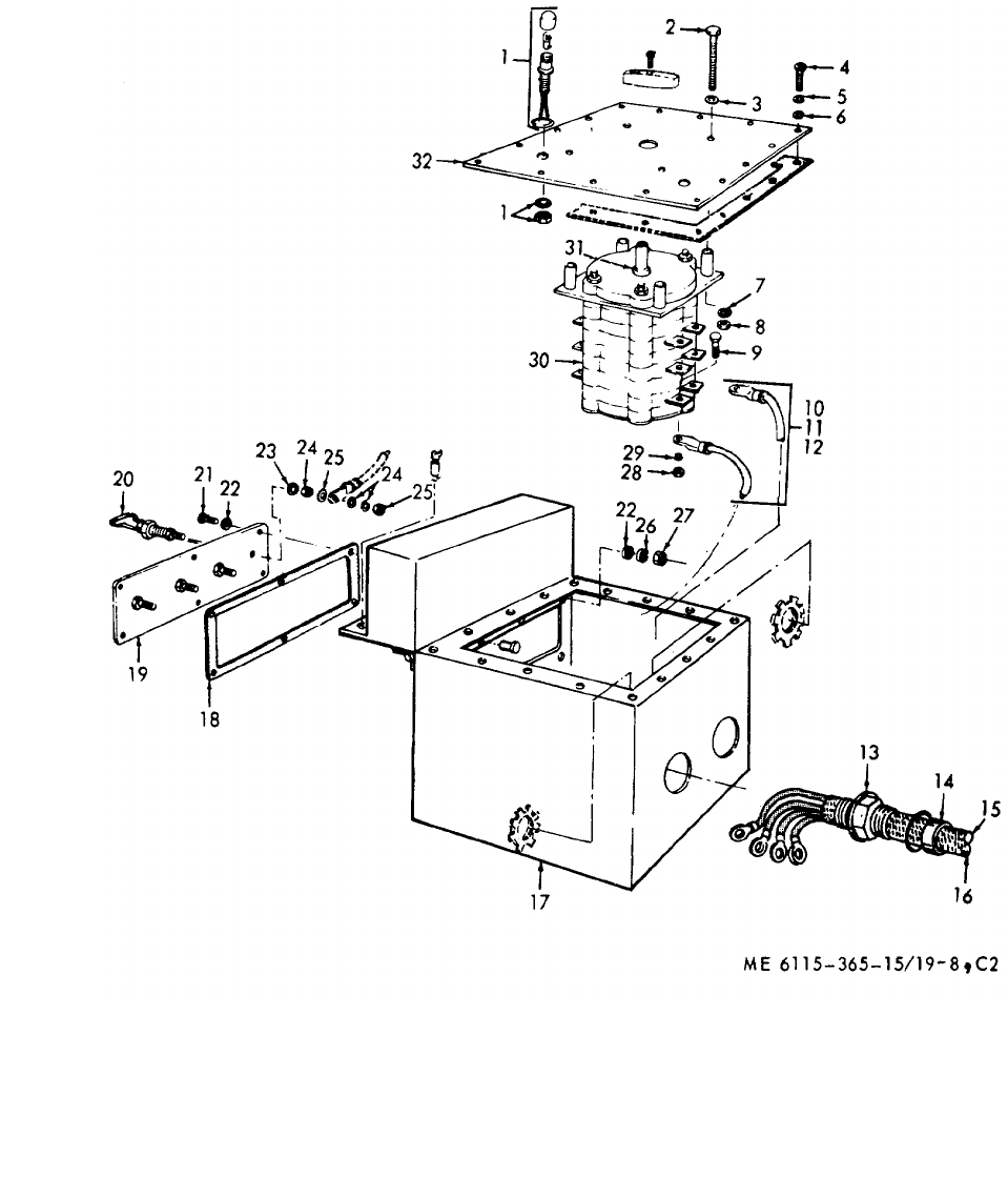
ME 6115-365-15/19-8, C2
TM 5-6115-365-15
C2
Figure 19-8. Generator transfer switch.
19-24
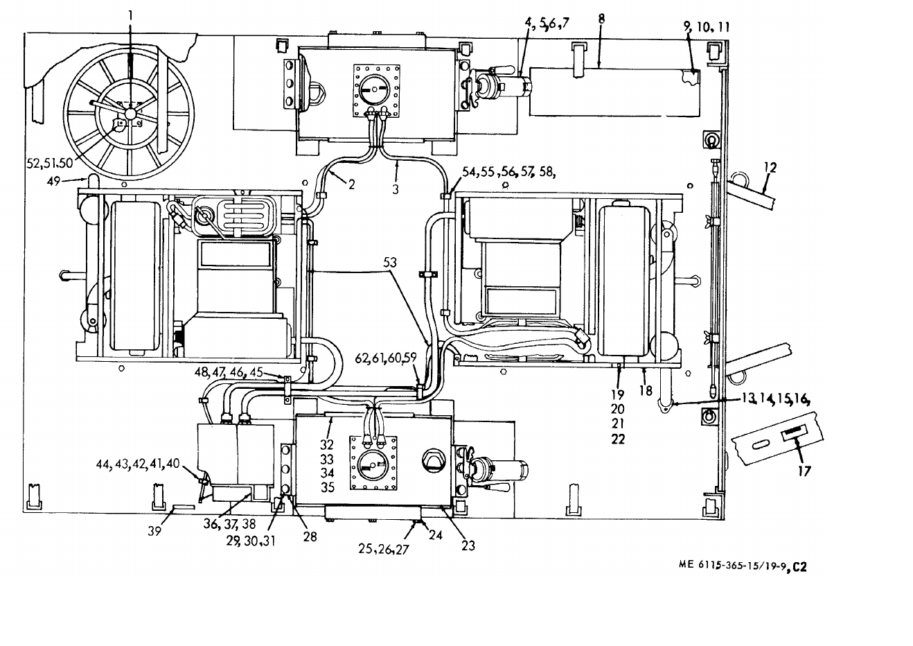
ME 6115-365-15/19-9, C2
TM 5-6115-365-15
C2
Figure 19-9. Power unit components.
19-25
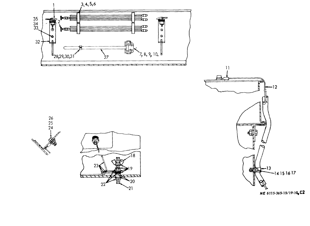
ME 6115-365-15/19-10, C2
TM 5-6115-365-15
C2
Figure 19-10. Detail components.
19-26
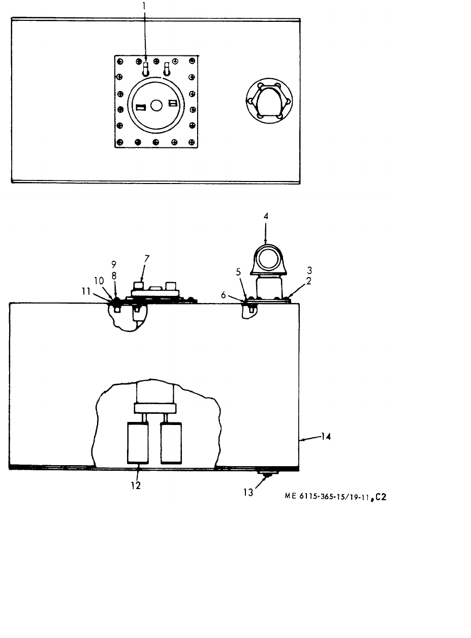
ME 6115-365-15/19-11, C2
TM 5-6115-365-15
C2
Figure 19-11. Fuel tank components.
19-27
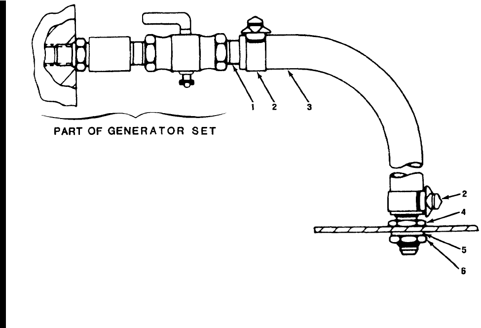
TM 5-6115-365-15
Figure 19-12. Oil drain assembly.
19-28 Change 8
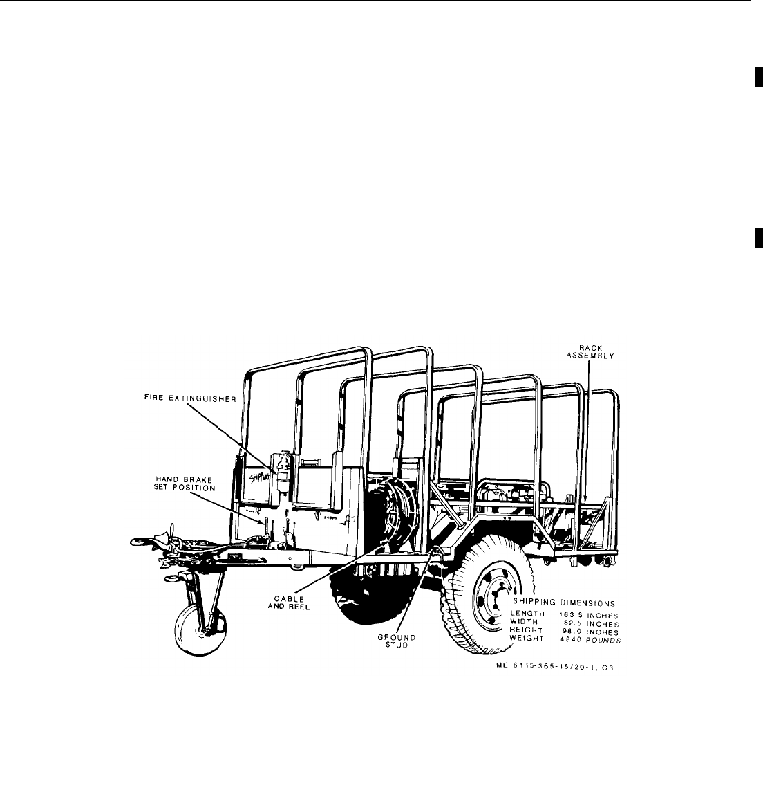
ME 6115-365-15/20-1, C3
TM 5-6115-365-15
C3
CHAPTER 20
GENERATOR SET, PU-631/G, FSN 6115-059-5172
Section I. DESCRIPTION AND DATA
20-1. Description
a. General. The trailer mounted generator set, PU-
631/G, consists of two 5 kw, Model SF 5.0 military
design generators mounted on a modified 1 1/2-ton, 2-
wheel cargo trailer, Model M-103-A3, (figures 20-1 and
20-2). Brackets, racks, holders, and platforms are
provided for transporting and installing communications
equipment. Table 20-1 lists components of the PU631/G
generator set.
b. Generators. Each Model SF 5.0, 5 kw generator
is powered by a directly-coupled, 2-cylinder, 10 hp,
military standard model 2A042-1 gasoline engine. For
description, operation, and maintenance of the
generators, refer to TM 5-6115-332-14. A power
transfer switch is provided for connecting the generators
to a common load.
c. Engines. For description, operation, and
maintenance information not covered in TM 5-6115-332-14,
refer to TM 5-2805-258-14.
d. Trailers. For description and maintenance of the
trailer chassis, refer to TM 9-2330-213-14.
e. Lubrication. For lubrication instructions for the
gasoline engines, refer to LO 5-2805-258-14; the trailer
lubrication information is contained in
LO 9-2330-213-12.
Figure 20-1. PU-631/G left front, 3/4 view
Change 8 20-1
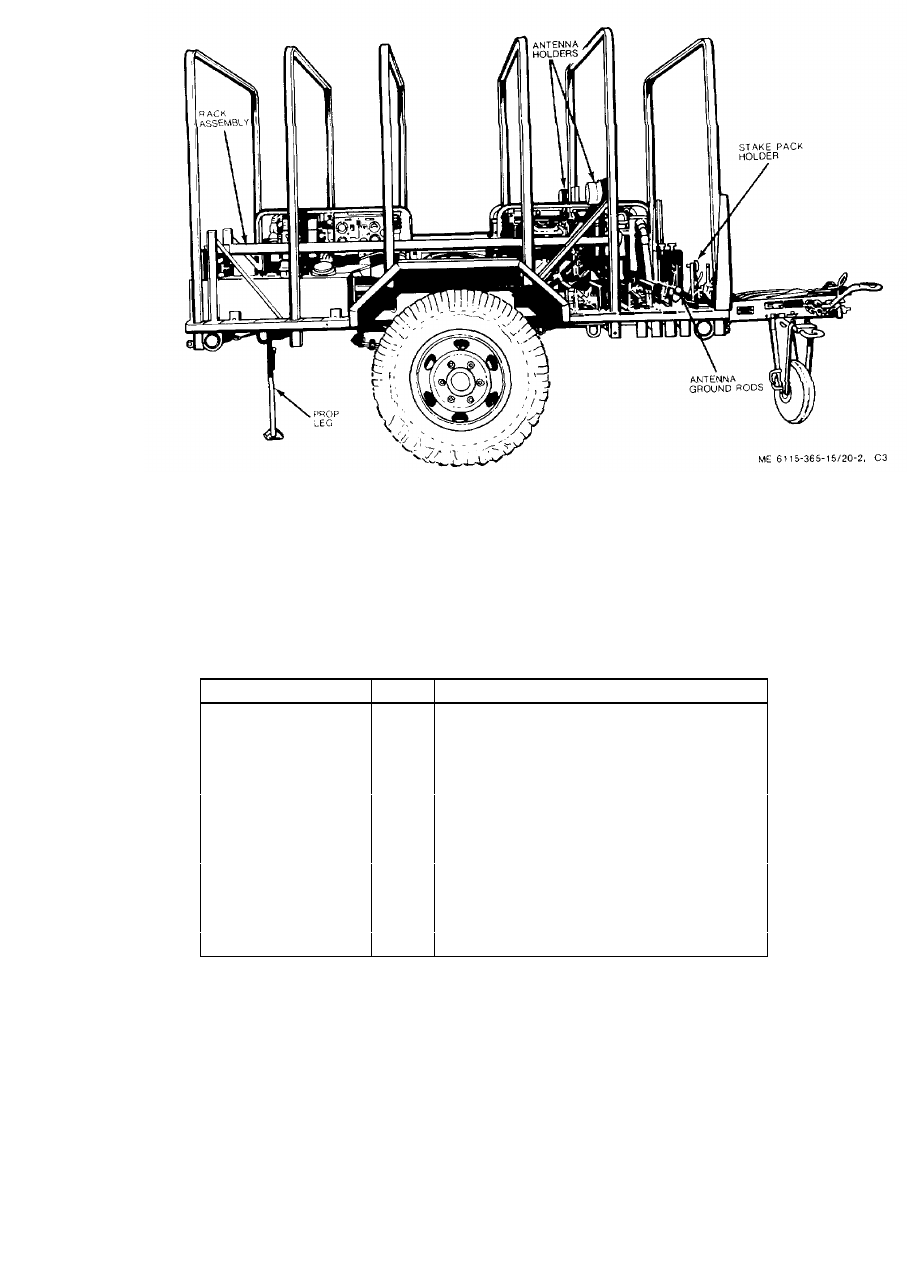
ME 6115-365-15/20-1, C3
TM 5-6115-365-15
Figure 20-2. PU-631/G right side
20-2. Tabulated Data
Table 20-1 lists components for the PU-631/G generator set.
Table 20-1. PU-631/G components.
FSN QTY Nomenclature
4210-555-8837 1Fire extinguisher
6115-017-8240 2Generator, 5 kw, Model SF 5.0 MD
5975-878-3791 2Ground rod w/attachments
2590-318-6691 1Leg prop assembly, trailer
5120-251-4489 1Sledge hammer
2330-141-8052 1Trailer, M103-A3
Section II. OPERATING INSTRUCTIONS
20-3. Setting-Up Instructions
a. Leveling.
(1) Locate the trailer on as level a surface as
possible in order for the generators to operate efficiently.
(2) Set brake and block wheels securely to
prevent any movement. Operate handbrake at weekly
intervals to insure freedom of movement.
(3) Pull leg prop down and adjust length for firm
contact with ground.
20-2 Change 8

ME 6115-365-15/20-1, C3
TM 5-6115-365-15
C3
WARNING
Wheels must be blocked, brakes set,
and leg prop down in support
position before attempting to roll up
the tarpaulin and before starting to
assemble or set up equipment for
operation.
b. Preparation for Starting.
(1) Remove canvas tarpaulin, roof bows,
splash shield, and racks.
(2) Remove all loose auxiliary items that
might block air flow through the trailer and around the
generator sets. CAUTION
It is of foremost importance that
there be free circulation of air around
the generator sets at all times during
operation.
c. Grounding
WARNING
Never operate the generator set until
it has been properly grounded.
Electrical defects in the load lines or
equipment can cause death by
electrocution.
(1) The ground may be any of three methods,
depending on the location and the terrain.
(a) A ground rod driven to a depth of 8
feet. (b) An underground metallic water
piping system. (c) A metal plate (9 square ft.) buried to
a depth of 4 feet.
(2) The ground lead must be No. 6 AWG
copper wire bolted or clamped to the rod, plate, or piping
system. (3) Connect the other end of the ground lead
to the trailer ground terminal.
d. Servicing. Service the generators as described
in TM 5-6115-332-12. Install the engine oil drain hoses.
Connect the load lines to the proper terminals on the
power transfer switchbox (Fig. 20-3).
20-4. Starting
WARNING
Never operate the generator set in an
enclosed area unless exhaust gases
are piped outside. Inhalation of
exhaust fumes may result in serious
illness or death.
Figure 20-3. Wiring diagram
20-3
TM 5-6115-365-15
C3
a.Perform the pre-starting operations in
TM 5-6115-332-12.
b. Position the transfer switch to the desired
generator.
c.Start the generator as described in
TM 5-6115-332-12.
20-5. Stopping
Stop the generator set as described in
TM 5-6115-332-12.
20-6. Operation
Operate the generator set as instructed in
TM 5-6115-332-12. Use fuel from the trailer mounted
fuel tank. When refueling tank, operate the engine with
fuel from the 5-gallon can until sediment has had a
chance to settle in the fuel tank. Use the fuel transfer
valve to perform fuel transfer operations.
Section III. OPERATOR'S MAINTENANCE INSTRUCTIONS
Operator's maintenance of the power unit is concerned
with keeping the generator sets lubricated; the fuel tank
filled; the battery electrolyte level maintained; and
cleaning and servicing the fuel filter and air cleaner filters
as described in TM 5-6115-332-12. Removal of dust
and dirt from the equipment is also a routine
maintenance function of the operator.
Section IV. ORGANIZATIONAL MAINTENANCE INSTRUCTIONS
20-7. Fuel System Components
(Fig. 20-4)
a. General. The fuel system consists of the fuel
tank mounted on the right-rear bed of the trailer; the fuel
filters located inside the fuel tank; the auxiliary 5-gallon
fuel tanks; and the hoses and fittings to provide fuel to
the gasoline engines. A fuel strainer in the filler neck is
removable for cleaning. The fuel level gage is located
on the top of the tank.
b. Fuel Filter Replacement
(1) Remove screws and washers that secure
gage base to fuel tank and remove gage assembly and
gasket. (2) Remove nuts and bolts securing filters to
tube base.
(3) Install new filters on assembly and secure
with bolts and nuts.
(4) Using new gasket install gage assembly
and secure with screws and washers.
c. Gage Replacement
(1) Remove screws that secure gage to
assembly and remove gage from tank. Remove gasket.
(2) Using a serviceable gage assembly and a
new gasket, reinstall gage and secure with screws.
20-8. Fuel Tank
(Fig. 20-4)
a. Removal
(1) Remove drain plug and drain fuel from
tank.
(2) Remove fuel gage assembly (para 20-7).
(3) Remove screws and washers that secure
filler neck to tank and remove filler neck and gasket.
(4) Remove nuts, washers, and capscrews
that secure and stancion and brace for curb-side
antenna bracket.
(5) Lift end stancion and bracket slightly and
slide fuel tank to the rear and off trailer bed.
(6) Purge and clean fuel tank in accordance
with TB ORD 1031.
b. Installation. Installation is reverse procedure of
removal. Install new fuel filters before reinstalling gage
assembly. Clean fuel filler screen before reinstalling fuel
filler neck.
20-9. Rack Assemblies
(figs. 20-1 and 20-2)
a. Removal
(1) Remove load from rack assembly.
(2) Remove nuts, washers, and capscrews
that secure rack to trailer bed and remove rack.
b. Disassembly
(1) Remove nuts, washers, and capscrews
that secure clamp to rear stancion. Remove clamp.
(2) Remove nuts, washers, and capscrews
that secure roller supports to the rack. Remove rollers.
(3) Knock out rivets and remove nylon
20-4
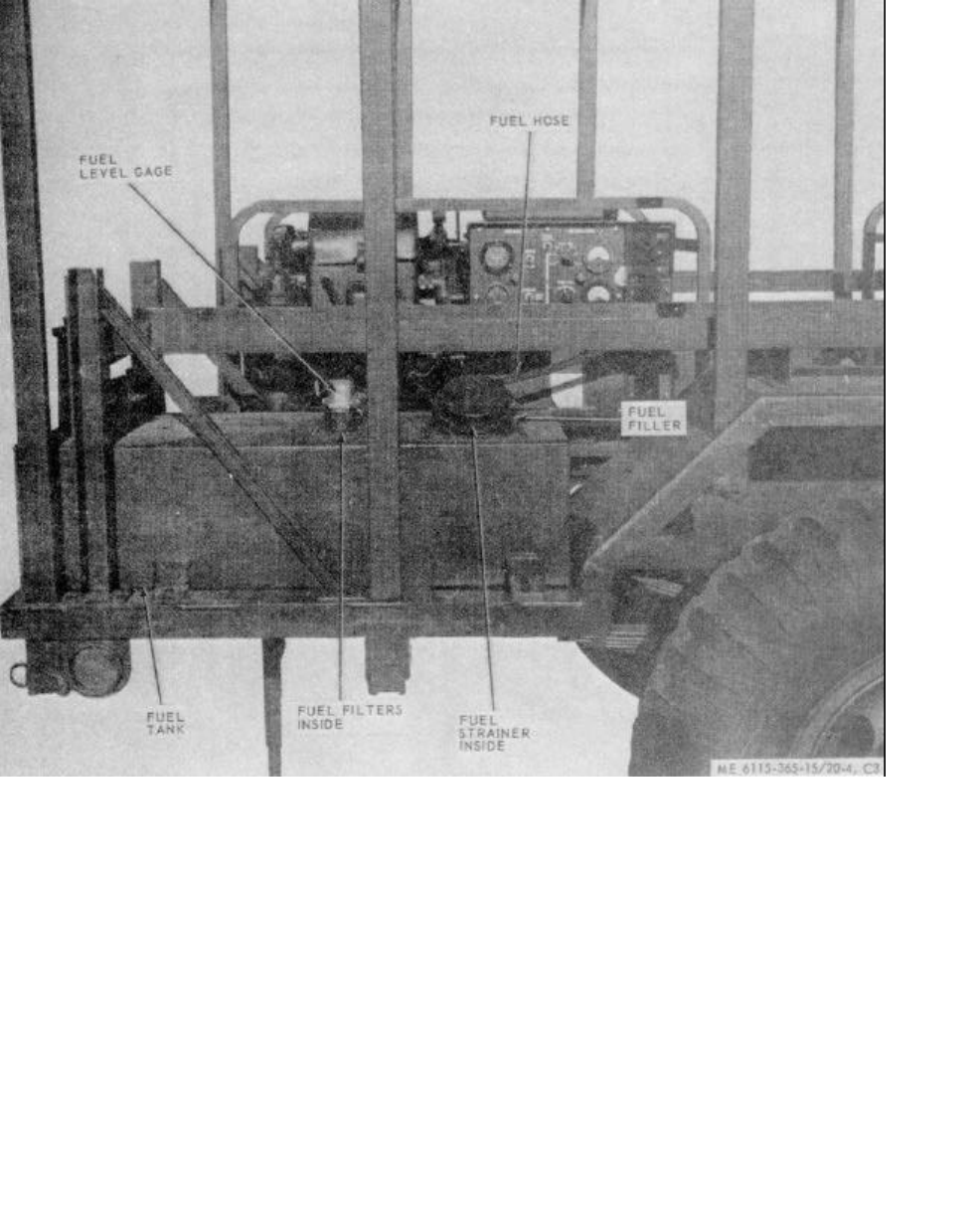
ME 6115-365-15/20-4, C3
TM 5-6115-365-15
C3
Figure 20-4. Fuel system components
runners from racks if nylon is to be replaced.
c. Reassembly. Using serviceable parts,
reassembly is reverse of procedure b above. Attach
nylon runners with rivets. Make sure the roller supports
are attached with the beveled edge to the outside of
stancion.
d. Installation. Installation is reverse of procedure
a above. Cover nylon runners with cloth tape if load is
not to be reinstalled on rack. Touch up with paint after
reassembly.
20-10. Accessory Box
(Fig. 20-5)
a. Removal
(1) Remove contents of box and stow in safe
place. (2) Remove nuts, washers, and capscrews
that secure box to trailer bed. Remove box.
b. Installation. Installation is reverse procedure of
removal, a above.
20-5
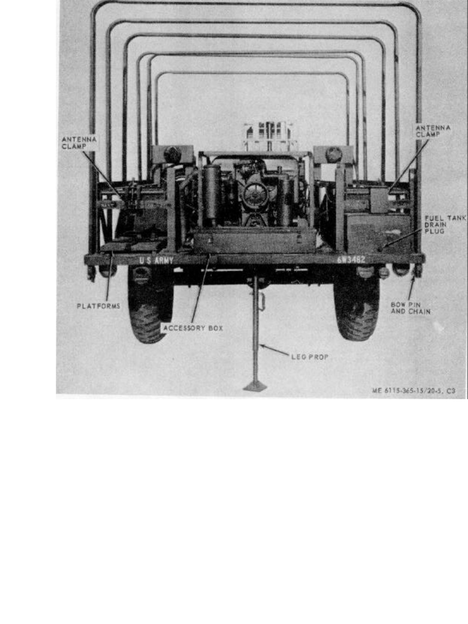
ME 6115-365-15/20-5, C3
TM 5-6115-365-15
C2
Figure 20-5. PU-631/G, rear view
20-11. Cable Reel
(Fig. 20-6)
a. Removal
(1) Remove pin from reel shaft and unscrew
shaft from reel support. Remove cable reel.
(2) Remove nuts, washers, and capscrews
that secure reel supports to trailer bed and remove
supports.
b. Installation. Installation is reverse of removal, a
above.
20-12. Platforms
(Fig. 20-5)
a. Removal. Remove nuts, washers, and
capscrews that secure perforated platforms to trailer bed
and remove platforms.
b. Repair. Repair platforms by replacement of
webbing straps, buckles, and strap ends.
c. Installation. Installation is reverse of removal, a
above.
20-6
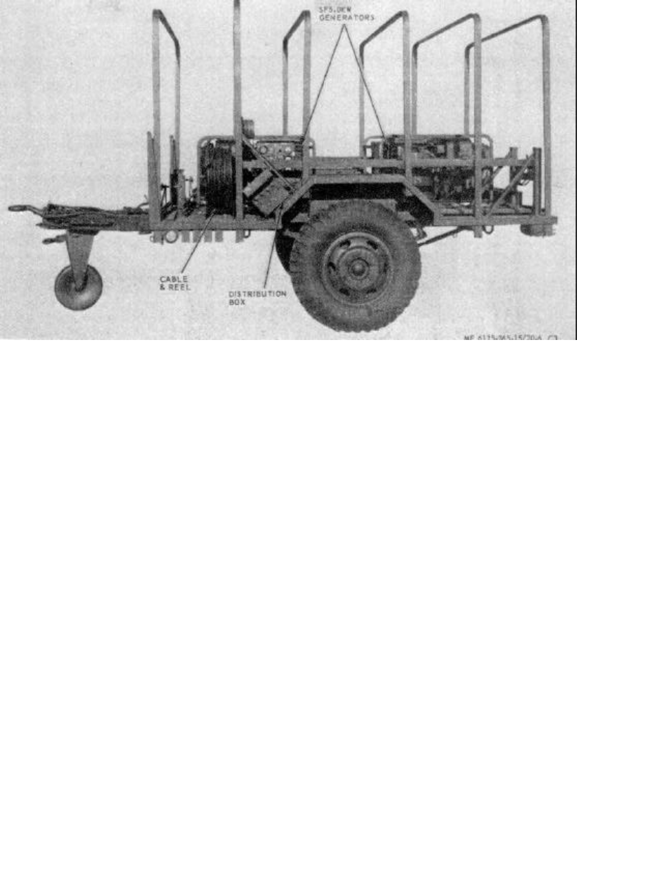
ME 6115-365-15/20-6, C3
TM 5-6115-365-15
C3
Figure 20-6. Electrical distribution system.
20-13. Tarpaulin, Roof Bows, and Leg Prop
(Fig. 20-5)
a. Removal
(1) Remove tarpaulin from unit.
(2) Pull out chain-secured pins that secure
roof bows to trailer bed and remove bows.
(3) Remove nuts, washers, and capscrews
that secure leg prop to rear of trailer and remove leg
prop.
b. Cleaning and Inspection.
(1) Clean tarpaulin and bows with water and
detergent. Clean leg prop with cleaning solvent. Dry
thoroughly.
(2) Inspect tarpaulin for tears, holes, broken
or missing ropes and straps, and other defects.
Inspect bows and leg prop for cracks, bends, or other
defects.
c. Installation. Installation is reverse of procedure
a above. Be sure tarpaulin is treated for waterproofing
and mildew resistance before reinstalling.
20-14. Transfer Switch Indicating Lamp
Replacement
Unscrew defective lamp from transfer switch box and
remove gasket. Install gasket on replacement lamp and
screw into base socket in transfer box.
Section V. DIRECT AND GENERAL SUPPORT AND DEPOT MAINTENANCE INSTRUCTIONS
20-15. Generator Set
(Fig. 20-7)
a. Removal.
(1) Disconnect fuel line at generator set.
(2) Disconnect electrical leads and load
cables.
(3) Disconnect oil drain adapter.
(4) Remove the battery.
(5) Disconnect exhaust pipe from engine.
(6) Remove nuts, washers, and cap
20-7
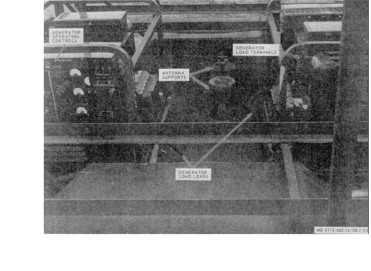
ME 6115-365-15/20-7, C3
TM 5-6115-365-15
C3
Figure 20-7. Generator sets
20-8
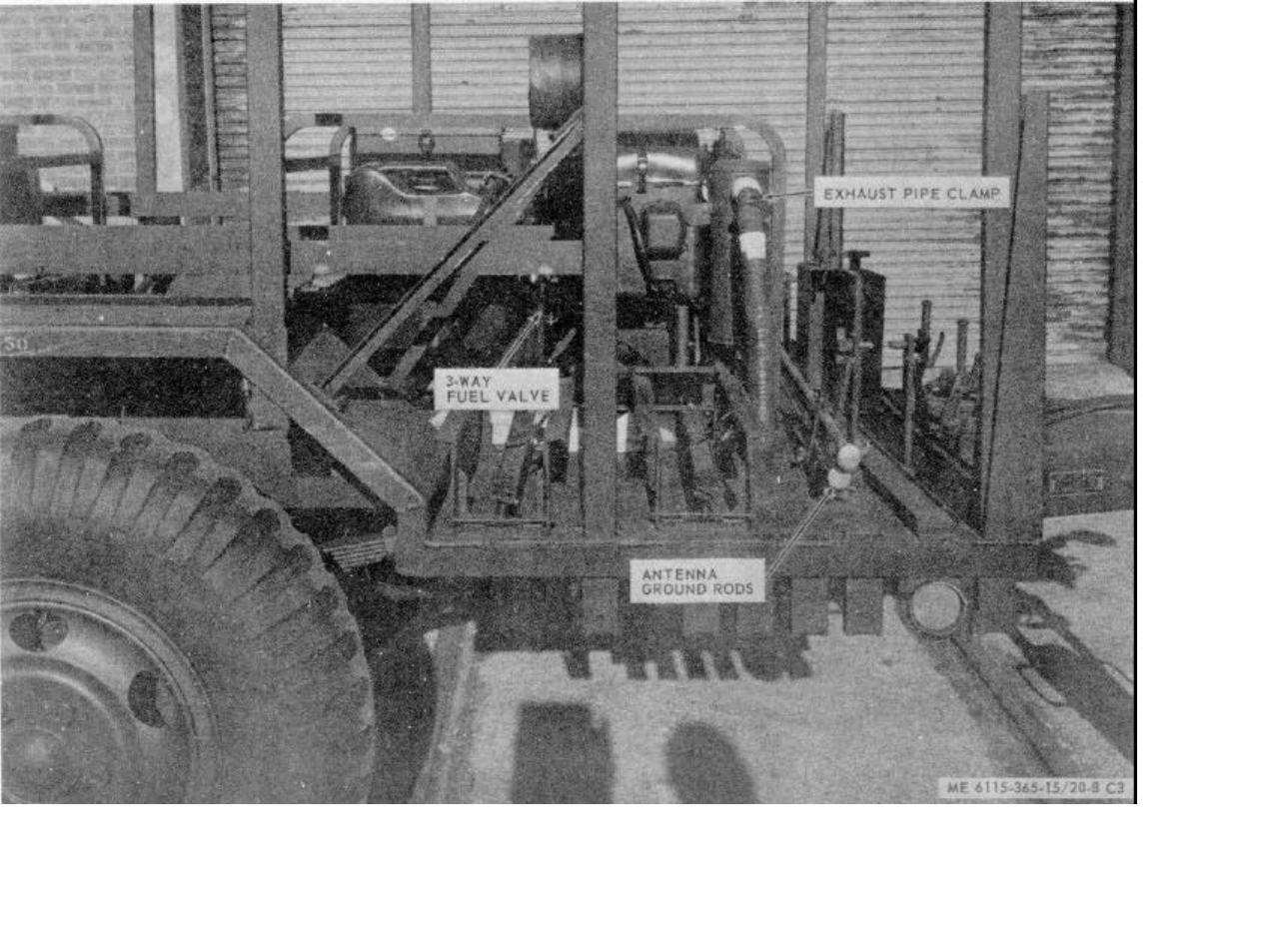
ME 6115-365-15/20-8, C3
TM 5-6115-365-15
C3
Figure 20-8. Ground rod, brackets, and holddowns
20-9
TM 5-6115-365-15
C3
screws that secure generator set to trailer body and
remove generator set.
b. Installation. Installation is reverse of removal
procedure a above. Make sure that the bevel washers
are properly positioned so that generator set is securely
mounted to the trailer body.
20-16. Generator Transfer Switch
a. Removal (Fig. 20-6)
(1) Disconnect the load lines and the ground
wire at the distributor box.
(2) Disconnect the generator load lines from
the generators and loosen the cable clamps so that the
cables will be removed with the distribution box.
(3) Remove nuts, washers, and capscrews
that secure distribution box to the trailer body and
remove box and cables as an assembly.
b. Disassembly. Refer to figure 20-9 and
disassemble the distribution box components. Tag the
cable ends for proper reassembly.
c. Reassembly. Reassembly is reverse of
disassembly procedure b above.
d. Installation. Installation is reverse of removal
procedure a above. Refer to figure 20-3 to assure that
electrical load cables are properly connected.
20-17. Trailer Body
a. Removal
(1) Remove tarpaulin and roof bows
(para 20-13).
(2) Remove rack assemblies (para 20-9).
(3) Remove accessory box (para 20-10).
(4) Remove fuel tank (para 20-8).
(5) Remove platforms (para 20-12).
(6) Remove cable reel (para 20-11).
(7) Remove distribution box (para 20-16).
(8) Remove generator sets (para 20-15).
(9) Remove remaining racks and holders
(Fig. 20-8).
(10) Disconnect and tag trailer wiring beneath
trailer bed.
(11) Remove nuts, washers, and bolts that
secure trailer body to chassis and remove body.
b. Installation. Using a serviceable trailer body,
reverse removal procedure a above. Apply touch-up
paint to securing hardware after complete reassembly.
Connect electrical system to prime mover and check for
proper operation of lights and signals.
20-10
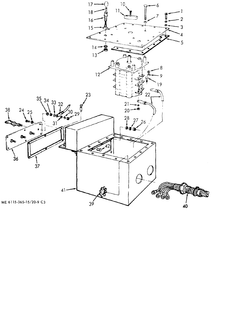
ME 6115-365-15/20-9,
C3
TM 5-6115-365-15
C3
1Screw 15 Preformed packing 29 Hex nut
2Lockwasher 16 Light and wire assy 30 Lockwasher
3Flat washer 17 Lens 31 Flat washer
4Cover 18 Lamp 32 Electrical lead
5Gasket 19 Screw 33 Flat washer
6Screw 20 Hex nut 34 Hex nut
7Flat washer 21 Lockwasher 35 Lockwasher
8Lockwasher 22 Electrical lead 36 Terminal board
9Hex nut 23 Fastener 37 Gasket
10 Screw 24 Screw 38 Terminal lug
11 Knob 25 Flat washer 39 Locknut
12 Transfer switch 26 Hex nut 40 Stuffing tube assy
13 Hex nut 27 Lockwasher 41 Transfer switch box
14 Lockwasher 28 Flat washer 42 Rivet
Figure 20-9. Generator distribution box
20-11
(1) (2) (3) (4) (5) (6) (7)
FEDERAL DESCRIPTION UNIT QTY 15-DAY ORGANIZATIONAL ILLUS-
SMR STOCK OF INC MAINTENANCE ALW RATION
CODE NUMBER USABLE MEAS IN (a) (b) (c) (d) (a) (b)
ON UNIT FIG ITEM
REF NUMBER & MFG CODE CODE 1-5 6-20 21-50 51-100 NO. NO.
TM 5-6115-365-15
C3
PART I - PU-631/G
0001 REPAIR PARTS FOR ORGANIZATIONAL
MAINTENANCE
00002 GROUP 03 - FUEL SYSTEM
00003 0306 - TANKS, LINES AND FITTINGS
PO2910-141-9758 CAP, FUEL TANK EA 1****20- 16
00004 MS35645-1 (96906) 10
X2 O5340-057-2907 CLAMP, LOOP EA 420- 48
00005 MS21333-74 (96906) 10
X2 OCLAMP, LOOP: 5/16 IN. NOM. ID, EA 320- 43
00006 MS21333-73 (96906) 10
PO4720-879-4091 HOSE ASSEMBLY, DETACHABLE: 5/16 IN. OD X 90 IN. LG EA 2* * 20- 42
00007 MS28741-5-0900 (96906) 10
PO4720-021-3320 HOSE ASSEMBLY, DETACHABLE: 5/16 IN. OD X 25 FT LGEA 1****20- 47
00008 MS28741-5-1440 (96906) 10
X2 O5310-877-5797 NUT, SELF-LOCKING: NO. 10-32 UNF 3B EA 320- 44
00009 MS21044N3 (96906) 10
X2 O5310-877-5797 NUT, SELF-LOCKING: NO. 10-32 UNF 3B EA 420- 49
00010 MS21044N3 (96906) 10
X2 O5305-984-7341 SCREW, MACHINE: COUNTERSUNK HEAD, NO. 10-32 X 5/8 IN. LG EA 320- 46
00011 MS35191-273 (96906) 10
X2 O5305-993-1851 SCREW, MACHINE: PAN HEAD,
00012 NO. 10-32 X 1 IN. LG EA 4 20-51
MS35207-267 (96906) 10
PO2910-470-1301 TANK ASSEMBLY, FUEL EA 120- 40
00013 13216E7510 (97403) 10
X2 OELBOW: 90 DEG, 5/16 IN. NOM. TUBE OD,
00014 EA 220- 17
SAEJ514 (81343) 10
PO2910-450-6565 FILTER, FUEL: 9.25 IN LG EA 2 224820- 6
00015 13216E7570-1 (97403) 10
X2 OFILLER, NECK EA 120- 13
00016 13216E7569 (97403) 10
X2 OGAGE, LIQUID LEVEL: 13.25 IN. LG EA 120- 11
00017 13216E7459-2 (97403) 10
PO5330-356-7904 GASKET, GAGE PLATE EA 1*22420- 8
00018 13216E7571 (97403) 15
PO5330-350-3965 GASKET, FILLER NECK EA 1*24420- 12
00019 13216E7572 (97403) 15
X2 O5310-984-3806 NUT, SELF-LOCKING: 5/16-18
00020 THD SIZE, TANK MTG EA 420- 2
MS51922-9 (96906) 15
X2 OPLATE, MOUNTING: FUEL GAGE EA 120- 7
00021 13216E7568 (97403) 15
X2 O4730-223-9268 PLUG, SQUARE HEAD PIPE: 1/4 IN. NPT EA 120- 5
00022 MS20913-2D (96906) 15
X2 O5306-225-8499 SCREW, CAP: 5/16-18 X 1 IN. LG,
00023 TANK MTG EA 420- 4
MS90725-34 (96906) 15
5305-989-7435 SCREW, MACHINE:PAN HEAD, NO. 10-32 X 5/8 IN. LG EA 14 20- 9
00024 MS35207-264 (96906) 15
20-12
(1) (2) (3) (4) (5) (6) (7)
FEDERAL DESCRIPTION UNIT QTY
15-DAY ORGANIZATIONAL
ILLUS-
SMR STOCK OF INC MAINTENANCE ALW RATION
CODE NUMBER USABLE MEAS IN (a) (b) (c) (d) (a) (b)
ON UNIT FIG
ITEM
REF NUMBER & MFG CODE CODE 1-5 6-20
21-50
51-100
NO. NO.
TM 5-6115-365-15
X2 O5305-989-7435 SCREW, MACHINE: PAN HEAD, EA 22 20-15 14
00025 NO. 10-32 X 5/8 IN. LG
MS35207-264 (96906)
X2 OTANK, FUEL EA 120-15 1
00026 13216E7567 (97403)
X2 O5310-081-4219 WASHER, FLAT: 5/16 IN. BSC, TANK MTG EA 420-15 3
00027 MS27183-12 (96906)
X2 O5310-045-3296 WASHER, LOCK: NO 10, NOM. SIZE, EA 22 20-15 15
00028 NECK MTG
MS35338-43 (96906)
X2 O5310-045-3296 WASHER, LOCK: NO. 10 NOM. SIZE, EA 14 20-15 10
00029 MS35338-43 (96906)
X2 O5310-014-5850 WASHER, FLAT EA 320-10 45
00030 MS27183-42 (96906)
X2 O5310-014-5850 WASHER, FLAT: NO. 10-32 THD SIZE EA 420-10 50
00031 MS27183-42 (96906)
00032 GROUP 15 - FRAME
00035 1507 - LEVELING JACKS
X2 O5310-087-4652 NUT, SELF-LOCKING, HEXAGON: 3/8-16 THD SIZE EA 320-13 22
00036 MS51922-17 (96906)
X2 O5305-269-3213 SCREW, CAP, HEXAGON HEAD: EA 320-13 23
00037 3/8-16 X 1 1/4 IN. LG
MS90725-62 (96906)
PO2590-318-6691 TRAILER LED PROP ASSEMBLY EA 1****20-13 24
00038 13214E1206 (97403)
00039 GROUP 18 - BODY
00040 1808 - STOWAGE RACKS, BOXES AND CABLE REELS
MD O6115-01-155-5363 ACCESSORY BOX EA 120-10 56
00041 13205E4949 (97403)
X2 OBRACKET, REEL EA 120-10 98
00042 13205E5092 (97403)
X2 O5340-999-6277 BRACKET, ASSEMBLY, SLEDGE HAMMER EA 120-11 18
00043 13214E1214 (97403)
X2 O2590-932-7298 CLAMP, GROUND ROD EA 420-11 14
00044 13212E3617 (97403)
X2 O2590-932-7298 CLAMP, GROUND ROD: 6 FT EA 220-10 10
00045 13212E3617 (97493)
X2 O5340-914-2578 CLIP, SPRING, SLEDGE HAMMER EA 120-11 23
00046 13214E1213-1 (97403)
X2 OHOLDER ASSEMBLY EA 120-10 25
00047 13216E7506 (97403)
X2 OHOLDER EA 120-18 1
00048 13216E7508 (97403)
X2 OCLAMP EA 120-18 3
00049 13216E7507 (97403)
X2 OKNOB: 5/16-18 UNC 2B EA 120-18 2
00050 13205E5105-2 (97403)
X2 O5315-143-6284 PIN, SPRING, CORROSION RESISTANT EA 120-18 5
00051 STEEL, 1/8 IN. DIA X 1 IN. LG
MS171534 (96906)
Change 8 20-13
(1) (2) (3) (4) (5) (6) (7)
FEDERAL DESCRIPTION UNIT QTY 15-DAY ORGANIZATIONAL ILLUS-
SMR STOCK OF INC MAINTENANCE ALW RATION
CODE NUMBER USABLE MEAS IN (a) (b) (c) (d) (a) (b)
ON UNIT FIG ITEM
REF NUMBER & MFG CODE CODE 1-5 6-20 21-50 51-100 NO. NO.
TM 5-6115-365-15
C3
X2 OSHAFT EA 120- 4
00052 13216E7509 (97403) 18
X2 OHOLDER ASSEMBLY EA 220- 21
00053 13216E7493 (97403) 10
X2 OHOLDER EA 120- 6
00054 13216E7495 (97403) 18
X2 OCLAMP EA 120- 7
00055 13216E7494 (97403) 18
X2 OKNOB: 5/16-18 UNC 2B EA 120- 11
00056 13205E5105-2 (97403) 18
X2 O5310-984-3806 NUT, SELF-LOCKING, HEXAGON:5/16-18 UNC EA 120- 15
00057 MS51922-9 (96906) 18
X2 O5315-842-3044 PIN, COTTER 3/32 IN. NOR. DIA X 3/4
00058 IN. LG EA 220- 10
MS24665-283 (96906) 18
X2 O5315-842-3044 PIN, COTTER: 3/32 IN. NOM. DIA X 3/4
00059 IN. LG EA 220- 14
MS24665-283 (96906) 18
X2 OTEE EA 120- 8
00060 13216E7496 (97403) 18
X2 OTEE EA 120- 12
00061 132167496 (97403) 18
X2 O5310-081-4219 WASHER, FLAT: 3/8 IN. BSC SIZE EA 320- 9
00062 MS27183-12 (96906) 18
X2 O5310-081-4219 WASHER, FLAT: 3/8 IN. BSC SIZE EA 320- 13
00063 MS27183-12 (96906) 18
12 O5310-933-8121 WASHER, LOCK: 1/4 IN. NOM. SIZE EA 220- 8
00064 MS35338-139 (96906) 13
X2 O5310-080-8495 NUT, PLAIN, WING: 1/4-20 UNC 2B EA 220- 7
00065 MS35425-39 (96906) 13
12 O5310-984-3806 NUT, SELF-LOCKING, HEXAGON: 5/16-18 UNC EA 12 20- 2
00066 MS51922-9 (96906) 10
X2 O5310-088-1251 NUT, SELF-LOCKING, HEXAGON EA 420- 7
00067 1/4-20 UNC 10
MS51922-1 (96906)
X2 O5310-088-1251 NUT, SELF-LOCKING, HEXAGON: 1/4-20 UNC EA 820- 22
00068 MS51922-1 (96906) 10
X2 O5310-984-3806 NUT, SELF-LOCKING: 5/16-18 UNC EA 820- 26
00069 MS51922-9 (96906) 10
X2 O5310-088-1251 NUT, SELF-LOCKING, HEXAGON: EA 420- 57
00070 MS51922-1 (96906) 10
X2 O5310-088-1251 NUT, SELF-LOCKING, HEXAGON: 1/4-20 UNC EA 16 20 67
00071 MS51922-1 (96906) 10
X2 O5310-088-1251 NUT, SELF-LOCKING, HEXAGON: 1/4-20 UNC EA 320- 81
00072 MS51922-1 (96906) 10
X2 O5310-088-1251 NUT, SELF-LOCK, HEXAGON EA 320- 84
00073 1/4-20 UNC 10
MS51922-1 (96906)
X2 O5310-088-1251 NUT, SELF-LOCKING, HEXAGON: EA 420- 99
00074 1/4-20 UNC 10
MS51922-1 (96906)
20-14

(1) (2) (3) (4) (5) (6) (7)
FEDERAL DESCRIPTION UNIT QTY 15-DAY ORGANIZATIONAL ILLUS-
SMR STOCK OF INC MAINTENANCE ALW RATION
CODE NUMBER USABLE MEAS IN (a) (b) (c) (d) (a) (b)
ON UNIT FIG ITEM
REF NUMBER & MFG CODE CODE 1-5 6-20 21-50 51-100 NO. NO.
TM 5-6115-365-15
C3
X2 O5310-984-3806 NUT, SELF-LOCKING, HEXAGON: EA 16 20- 7
00075 5/16-18 UNC 11
MS51922-9 (96906)
X2 O5310-088-1251 NUT, SELF-LOCKING: 1/4-20 UNC EA 820- 15
00076 MS51922-1 (96906) 11
X2 O5310-088-1251 NUT, SELF-LOCKING, HEXAGON: 1/4-20 UNC EA 220- 19
00077 MS51922-1 (96906) 11
X2 O5310-088-1251 NUT, SELF-LOCKING, HEXAGON: 1/4-20 UNC EA 120- 24
00078 MS51922-1 (96906) 11
X2 O5310-088-1251 NUT, SELF-LOCKING, HEXAGON: 1/4-20 UNC EA 16 20- 2
00079 MS51922-1 (96906) 16
X2 O5310-984-3806 NUT, SELF-LOCKING, HEXAGON: 5/16-18 UNC EA 16 20- 5
00080 MS51922-9 (96906) 16
X2 O5310-088-1251 NUT, SELF-LOCKING: 1/4-20 UNC EA 16 20- 1
00081 MS51922-1 (96906) 17
X2 O5310-984-3806 NUT, SELF-LOCKING EA 16 20- 4
00082 MS51922-9 (96906) 17
PO5315-059-0206 PIN, COTTER: STEEL CADMIUM PLATED, 3/16 IN. DIA X
00083 1 IN. LG, REEL SHAFT EA 1****
MS24665-491 (96906)
X2 OPLATFORM EA 420- 66
00084 13216E7503 (97403) 10
X2 ORACX EA 120- 5
00085 13216E7497 (97403) 10
X2 ORACK EA 220- 6
00086 13216E7502 (97403) 11
X2 ORACK ASSEMBLY, CURBSIDE EA 120- 41
00087 13216E7513 (97403) 10
X2 ORACK, CURBSIDE EA 120- 7
00088 13216E7514 (97403) 17
X2 OBRACKET EA 120- 12
00089 13216E7517 (97403) 17
X2 OBRACKET EA 220- 13
00090 13216E7521 (97403) 17
X2 OCLAMP EA 120- 22
00091 13216E7515 (97403) 17
X2 O5310-877-5797 NUT, SELF-LOCKING. NO. 10-32 UNF 3B EA 26 20- 9
00092 MS21044N3 (96906) 17
X2 O5310-088-1251 NUT, SELF-LOCKING: 1/4-20 UNC EA 420- 14
00093 MS51922-1 (96906) 17
X2 O5310-088-1251 NUT, SELF-LOCKING: 1/4-20 UNC EA 220- 19
00094 MS51922-1 (96906) 17
X2 O5310-088-1251 NUT, SELF-LOCKING, HEXAGON: 1/4-20 UNC EA 220- 27
00095 MS51922-1 (96906) 17
X2 O5315-839-5822 PIN, COTTER: 1/8 X 1 IN. LG EA 120- 23
00096 MS24665-353 (96906) 17
X2 O5315-842-3154 PIN, STRAIGHT HEADED:1/2 X 1 27/64 IN. LG EA 120- 25
00097 MS35810-36 (96906) 17
X2 ORUNNER, NYLON EA 220- 8
00098 13216E7520 (97403) 17
20-15
(1) (2) (3) (4) (5) (6) (7)
FEDERAL DESCRIPTION UNIT QTY 15-DAY ORGANIZATIONAL ILLUS-
SMR STOCK OF INC MAINTENANCE ALW RATION
CODE NUMBER USABLE MEAS IN (a) (b) (c) (d) (a) (b)
ON UNIT FIG ITEM
REF NUMBER & MFG CODE CODE 1-5 6-20 21-50 51-100 NO. NO.
TM 5-6115-365-15
C3
X2 O5305-071-2234 SCREW, CAP, HEXAGON HEAD: 1/4-20 X 2 3/4 IN. LG EA 420- 16
00099 MS90725-17 (96906) 17
X2 O5305-071-2234 SCREW, CAP, HEXAGON READ: 1/4-20 X 2 3/4 IN. LG EA 220- 21
00100 MS90725-17 (96906) 17
X2 O5305-071-2234 SCREW, CAP, HEXAGON HEAD: 1/4-20 X 2 3/4 IN. LG EA 220- 29
00101 MS90725-17 (96906) 17
X2 O5305-993-1848 SCREW, MACHINE: PAN HEAD, EA 26 20- 11
00102 NO. 10-32 X 3/4 IN. LG 17
MS35207-265 (96906)
X2 OSUPPORT, ROLLER EA 120- 18
00103 13216E7518 (97403) 17
X2 OSUPPORT, ROLLER EA 120- 26
00104 13216E7519 (97403) 17
X2 O5310-809-8546 WASHER, FLAT: NO. 10-32 BSC SIZE EA 26 20- 10
00105 MS27183-8 (96906) 17
X2 O5310-809-4058 WASHER, FLAT: 1/4-20 BSC SIZE EA 420- 15
00106 MS27183-10 (96906) 17
X2 O5310-809-4058 WASHER, FLAT: 1/4-20 BSC SIZE EA 220- 20
00107 MS27183-10 (96906) 17
X2 O5310-809-5998 WASHER, FLAT: 1/2 IN. BSC SIZE EA 120- 24
00108 MS27183-18 (96906) 17
X2 O5310-809-4058 WASHER, FLAT: 1/4-20 BSC SIZE EA 220- 28
00109 MS27183-10 (96906) 17
X2 ORACK ASSEMBLY, ROADSIDE EA 120- 65
00110 13216E7511 (97403) 10
X2ORACK, ROADSIDE EA 120- 1
00111 13216E7512 (97403) 16
X2 OBRACE: 3.62 IN. LG EA 120- 80
00112 13216E7522-2 (97403) 10
X2 OBRACKET: EA 120- 12
00113 13216E7517 (97403) 16
X2 OBRACKET EA 220- 13
00114 13216E7521 (97403) 16
X2 OCLAMP EA 120- 22
00115 13216E7515 (97403) 16
X2 O5310-877-5797 NUT, SELF-LOCKING, HEXAGON: EA 26 20- 9
00116 NO. 10-32 UNF 38 16
MS21044N3 (96906)
X2 O5310-088-1251 NUT, SELF-LOCKING, HEXAGON: EA 420- 14
00117 1/4-20 UNC 16
MS51922-1 (96906)
X2 O5310-088-1251 NUT, SELF-LOCKING, HEXAGON:1/4-20 UNC EA 220- 19
00118 MS51922-1 (96906) 16
X2 O5310-088-1251 NUT, SELF-LOCKING, HEXAGON:1/4-20 UNC EA 220- 27
00119 MS51922-1 (96906) 16
X2 O5315-839-5822 PIN, COTTER: 1/8 IN. DIA X 1 IN. LG EA 120- 23
00120 MS24665-353 (96906) 16
X2 O5315-842-3154 PIN, STRAIGHT HEADED:1/2 IN. DIA X 1 27/64 IN. LG EA 120- 25
00121 MS35810-36 (96906) 16
X2 OROLLER EA 120- 17
00122 13216E7523 (97403) 16
20-16
(1) (2) (3) (4) (5) (6) (7)
FEDERAL DESCRIPTION UNIT QTY 15-DAY ORGANIZATIONAL ILLUS-
SMR STOCK OF INC MAINTENANCE ALW RATION
CODE NUMBER USABLE MEAS IN (a) (b) (c) (d) (a) (b)
ON UNIT FIG ITEM
REF NUMBER & MFG CODE CODE 1-5 6-20 21-50 51-100 NO. NO.
TM 5-6115-365-15
C3
X2 OROLLER EA 120- 17
00123 13216E7523 (97403) 17
X2 ORUNNER, NYLON EA 220- 8
00124 13216E7520 (97403) 16
X2 O5305-071-2234 SCREW, CAP, HEXAGON HEAD: 1/4-20 X 2 3/4
00125 IN. LG EA 420- 16
MS90725-17 (96906) 16
X2 O5305-071-2234 SCREW, CAP, HEXAGON HEAD: 1/4-20 X 2 3/4
00126 IN. LG EA 220- 21
MS90725-17 (96906) 16
X2 O5305-071-2234 SCREW, CAP, HEXAGON HEAD:1/4-20 X 2 3/4
00127 IN. LG EA 220- 29
MS90725-17 (96906) 16
X2 O5305-993-1848 SCREW, MACHINE: PAN HEAD, NO. 10-32 X 3/4
00128 IN. LG EA 26 20- 11
MS35207-265 (96906) 16
X2 OSUPPORT, ROLLER EA 120- 18
00129 13216E7518 (97403) 16
X2 OSUPPORT, ROLLER EA 120- 26
00130 13216E7519 (97403) 16
X2 O5310-809-8546 WASHER, FLAX: NO. 10-32 BSC SIZE EA 26 20- 10
00131 MS27183-8 (96906) 16
X2 O5310-809-4058 WASHER, FLAT: 1/4-20 BSC SIZE EA 420- 15
00132 MS27183-10 (96906) 16
X2 O5310-809-4058 WASHER, FLAT: 1/4-20 BSC SIZE EA 220- 20
00133 MS27183-10 (96906) 16
X2 O5310-809-5998 WASHER, FLAT: 1/2 IN. BSC SIZE EA 120- 24
00134 MS27183-18 (96906) 16
X2 O5310-809-4058 WASHER, FLAT: 1/4-20 BSC SIZE EA 220- 28
00135 MS27183-10 (96906) 16
X2 OREEL, CABLE EA 120- 97
00136 13214E1425 (97403) 10
X2 O5306-225-9081 SCREW, CAP, HEXAGON HEAD:5/16-18 X 1 1/4
00137 IN. LG EA 620- 4
MS90725-36 (96906) 10
X2 O5305-225-3839 SCREW, CAP, HEXAGON HEAD: 1/4-20 X 1 IN. LG EA 820- 24
00138 MS90725-8 (96906) 10
X2 O5306-225-9081 SCREW, CAP, HEXAGON HEAD: 5/16 X 1 1/4 IN.LG EA 820- 28
00139 MS90725-36 (96906) 10
X2 O5305-225-3839 SCREW, CAP, HEXAGON HEAD: 1/4-20 X 1 IN. LG EA 420- 59
00140 MS90725-8 (96906) 10
X2 O5305-225-3839 SCREW, CAP, HEXAGON HEAD: 1/4-20 X 1 IN. IL EA 16 20- 69
00141 MS90725-8 (96906) 10
X2 O5305-068-0502 SCREW, CAP, HEXAGON HEAD: 1/4-20 X 3/4 IN. LG EA 320- 83
00142 MS90725-6 (96906) 10
X2 O5305-225-3839 SCREW, CAP, HEXAGON HEAD: 1/4-20 X 1 IN. LG EA 320- 86
00143 MS90725-8 (96906) 10
X2 O5305-068-0502 SCREW, CAP, HEXAGON HEAD: 1/4-20 X 3/4 IN. LG EA 420- 101
00144 MS90725-6 (96906) 10
X2 O5305-068-0502 SCREW, CAP, HEXAGON HEAD: 1/4-20 X 3/4 IN. LG EA 220- 21
00145 MS90725-6 (96906) 11
20-17

(1) (2) (3) (4) (5) (6) (7)
FEDERAL DESCRIPTION UNIT QTY 15-DAY ORGANIZATIONAL ILLUS-
SMR STOCK OF INC MAINTENANCE ALW RATION
CODE NUMBER USABLE MEAS IN (a) (b) (c) (d) (a) (b)
ON UNIT FIG ITEM
REF NUMBER & MFG CODE CODE 1-5 6-20 21-50 51-100 NO. NO.
TM 5-6115-365-15
C3
X2 O5305-068-0502 SCREW, CAP, HEXAGON HEAD: 1/4-20 X 3/4 IN. LG EA 120- 26
00146 MS90725-6 (96906) 11
X2 O5305-721-8010 SCREW, CAP, HEXAGON: 1/4-20 X 2 IN. LG EA 220- 10
00147 MS35307-314 (96906) 13
X2 O5305-225-3839 SCREW, CAP, HEXAGON HEAD:1/4-20 UNC X 1 IN. LG EA 16 20- 4
00148 MS90725-8 (96906) 16
X2 O5305-225-8499 SCREW, CAP, HEXAGON HEAD:5/16-18 X 1 IN. LG EA 16 20- 7
00149 MS90725-A4 (96906) 16
X2 O5305-225-3839 SCREW, CAP, HEXAGON HEAD: 1/4-20 X 1 IN. LG EA 16 20- 3
00150 MS90725-8 (96906) 17
X2 O5305-225-8499 SCREW, CAP, HEXAGON HEAD :5/16-18 X 1 IN. LG EA 16 20- 6
00151 MS90725-34 (96906) 17
X2 O5305-225-3839 SCREW, MACHINE: 1/4-20 X 1 IN. LG EA 820- 17
00152 MS90725-8 (96906) 11
X2 O5305-958-6073 SCREW, MACHINE: 82 DEG, FLAT, 5/16-18 X
00153 1 3/4 IN. LG EA 620- 1
MS35190-309 (96906) 10
X2 O5309-071-2241 SCREW, MACHINE: 82 DEG, FLAT, EA 420- 9
00154 1/4-20 X 1 1/4 IN. LG 10
MS90725-10 (96906)
X2 OSHIELD EA 120- 6
00155 13216E7433 (97403) 13
X2 OSUPPORT, REEL EA 120- 102
00156 13205E5093 (97403) 10
X2 O5310-081-4219 WASHER, FLAT: 5/16 IN. BSC SIZE EA 12 20- 3
00157 MS27183-12 (96906) 10
X2 O5310-809-3078 WASHER, FLAT: 1/4 IN. BSC SIZE EA 420- 8
00158 MS27183-11 (96906) 10
X2 O5310-809-3078 WASHER, FLAT: 1/4 IN. BSC SIZE EA 820- 23
00159 MS27183-11 (96906) 10
X2 O5310-081-4219 WASHER, FLAT: 5/16 IN. BSC SIZE EA 820- 27
00160 MS27183-12 (96906) 10
X2 O5310-809-3078 WASHER, FLAT: 1/4-20 BSC SIZE EA 420- 58
00161 MS27183-11 (96906) 10
X2 O5310-809-3078 WASHER, FLAT: 1/4-20 IN. BSC SIZE EA 16 20- 68
00162 MS27183-11 (96906) 10
X2 O5310-809-3078 WASHER, FLAT: 1/4-20 IN. BSC SIZE EA 320- 82
00163 MS27183-11 (96906) 10
X2 O5310-809-3078 WASHER, FLAT: 1/4-20 IN. BSC SIZE EA 320- 85
00164 MS27183-11 (96906) 10
X2 O5310-809-3078 WASHER, FLAT: 1/4-20 IN. BSC SIZE EA 420- 100
00165 MS27183-11 (96906) 10
X2 O5310-081-4219 WASHER, FLAT: 5/16 IN. BSC SIZE EA 16 20- 8
00166 MS27183-12 (96906) 11
X2 O5310-809-3078 WASHER, FLAT: 1/4 IN. BSC SIZE EA 820- 16
00167 MS27183-11 (96906) 11
X2 O5310-809-3078 WASHER, FLAT: 1/4 IN. BSC SIZE EA 220- 20
00168 MS27183-11 (96906) 11
X2 O5310-809-3078 WASHER, FLAT: 1/4 IN. BSC SIZE EA 120- 25
00169 MS27183-11 (96906) 11
20-18

(1) (2) (3) (4) (5) (6) (7)
FEDERAL DESCRIPTION UNIT QTY 15-DAY ORGANIZATIONAL ILLUS-
SMR STOCK OF INC MAINTENANCE ALW RATION
CODE NUMBER USABLE MEAS IN (a) (b) (c) (d) (a) (b)
ON UNIT FIG ITEM
REF NUMBER & MFG CODE CODE 1-5 6-20 21-50 51-100 NO. NO.
TM 5-6115-365-15
C3
X2 O5310-809-4058 WASHER, FLAT: 1/4 IN. BSC SIZE EA 420- 9
00170 MS27183-10 (96906) 13
X2 O5310-809-3078 WASHER, FLAT: 1/4-20 IN. BSC SIZE EA 16 20- 3
00171 MS27183-11 (96906) 16
X2 O5310-081-4219 WASHER, FLAT: 5/16-18 IN. BSC SIZE EA 16 20- 6
00172 MS27183-12 (96906) 16
X2 O5310-809-3078 WASHER, FLAT: 1/4 IN. BSC SIZE EA 16 20- 2
00173 MS27183-11 (96906) 17
X2 O5310-081-4219 WASHER, FLAT: 5/16 IN. BSC SIZE EA 16 20- 5
00174 MS27183-12 (96906) 17
00175 1810 - CARGO BODY
X2 OBRACE EA 120- 33
00178 13216E7522-1 (97403) 10
X2 O5310-087-4652 NUT, SELF-LOCKING, HEXAGON: 3/8-16 UNC EA 12 20- 1
00180 MS51922-17 (969065 13
X2 O5310-088-1251 NUT, SELF-LOCKING, HEXAGON: 1/4-20 UNC EA 320- 34
00181 MS51922-1 (96906) 10
X2 O5310-088-1251 NUT, SELF-LOCKING: 1/4-20 UNC EA 320- 37
00182 MS51922-1 (96906) 10
X2 O5305-269-3211 SCREW, CAP, HEXAGON HEAD: 3/8-16 X 1 IN. LG EA 16 20- 5
00184 MS90725-60 (96906) 13
X2 O5305-068-0502 SCREW, CAP, HEXAGON HEAD: 1/4-20 X 3/4 IN. L5 EA 320- 36
00185 MS90725-6 (96906) 10
X2 O5305-225-3839 SCREW, CAP, HEXAGON HEAD:1/4-20 X 1 IN. LG EA 320- 39
00186 MS90725-8 (96906) 10
X2 O5310-080-6004 WASHER, FLAT: 3/8 IN. BSC SIZE EA 16 20- 3
00189 MS27183-14 (96906) 13
X2 O5310-637-9541 WASHER, LOCK: 3/8 IN. NON. BSC SIZE EA 420- 2
00190 MS35338-46 (96906) 13
X2 O5310-809-3078 WASHER, FLAT: 1/4 IN. BSC SIZE EA 320- 35
00191 MS27183-11 (96906) 10
X2 O5310-809-3078 WASHER, FLAT: 1/4 IN. BSC SIZE EA 320- 38
00192 MS27183-11 (96906) 10
00193 GROUP 22 - BODY ACCESSORY ITEMS
00194 2201 - CANVAS ITEMS
X2 O5340-764-2334 LOOP, STRAP, FASTENER: 1 1/4 IN. SIZE EA 720- 71
00195 MS51939-1 (96906) 10
X2 O5340-764-2334 LOOP, STRAP, FASTENER: 1 1/4 IN. SIZE EA 620- 76
00196 MS51939-1 (96906) 10
X2 O5340-764-2334 LOOP, STRAP, FASTENER: 1 1/4 IN. SIZE EA 120- 88
00197 MS51939-1 (96906) 10
X2 O5310-811-3494 NUT, SELF-LOCKING, HEXAGON NO. 8-32 UNC 3B EA 14 20- 72
00198 MS21044008 (96906) 10
X2 O5310-811-3494 NUT, SELF-LOCKING HEXAGON: NO. 8-32 UNC 3B EA 12 20- 77
00199 MS21044N08 (969065 10
X2 O5310-811-3494 NUT, SELF-LOCKINGHEXAGON: NO. 8-32 UNC 3B EA 220- 89
00200 MS21044N08 (96906) 10
20-19

(1) (2) (3) (4) (5) (6) (7)
FEDERAL DESCRIPTION UNIT QTY 15-DAY ORGANIZATIONAL ILLUS-
SMR STOCK OF INC MAINTENANCE ALW RATION
CODE NUMBER USABLE MEAS IN (a) (b) (c) (d) (a) (b)
ON UNIT FIG ITEM
REF NUMBER & MFG CODE CODE 1-5 6-20 21-50 51-100 NO. NO.
TM 5-6115-365-15
C3
X2 O5305-984-6195 SCREW, MACHINE: PAN HEAD, NO. 8-32 X 3/4 IN. LG EA 14 20- 74
00201 MS35206-247 (96906) 10
X2 O5305-984-6195 SCREW, MACHINE: PAN HEAD, NO. 8-32 X 3/4 IN. LG E220- 79
00202 MS35206-247 (96906) 10
X2 O5305-984-6195 SCREW, MACHINE: PAN HEAD, NO. 8-32 X 3/4 IN. LG EA 220- 91
00203 MS35206-247 (96906) 10
PO5340-195-5656 STRAP, WEBBING: 22 IN. LG EA 7****20- 70
00204 13216E7504 (97403) 10
PO5340-197-5029 STRAP, WEBBING: 21 IN. LG EA 6****20- 75
00205 13216E7505-1 (97403) 10
PO5340-409-3880 STRAP, WEBBING: 34 IN. LG EA 1****20- 87
00206 13216E7505-2 (97403) 10
POR 6115-459-5946 TARPAULIN EA 1***220- 12
00207 13216E7434 (97403) 13
X2 OWASHER, FLAT: NO. 8-32 BSC SIZE EA 14 20- 73
00208 MS27183-41 (96906) 10
X2 OWASHER, FLAT: NO. 8-32 BSC SIZE EA 12 20- 78
00209 MS27183-41 (96906) 10
X2 OWASHER, FLAT: NO. 8-32 BSC SIZE EA 220- 90
00210 MS27183-41 (96906) 10
00211 2202 - ACCESSORY ITEMS
PO2540-924-8478 BOW, TRAILER TARPAULIN: 68 IN. H EA 4****20- 11
00212 13212E3597-1 (97.403) 13
PO2540-926-1003 BOW, TRAILER TARPAULIN: 55.75 IN. H EA 2****20- 13
00213 13212E3597-2 (97403) 13
X2 O5310-088-1251 NUT, SELF-LOCKING: 1/4-20 IN. UNC EA 820- 15
00214 MS51922-1 (96906) 13
X2 O5310-088-1251 NUT, SELF-LOCKING, HEXAGON:1/4-20 IN. UNC EA 420- 19
00215 MS51922-1 (96906) 13
PO9905-202-3639 REFLECTOR, AMBER CLEARANCE INDICATOR EA 2****20- 18
00216 MS35387-2 (96906) 13
PO9905-205-2795 REFLECTOR, RED, CLEARANCE INDICATOR EA 4***220- 14
00217 MS35387-1 (96906) 13
PO5975-928-8865 ROD, GROUND: 6 FT EA 2****20- 6
00218 MILR11461TYPE2STYLE3 (81349) 10
X2 O5305-068-0500 SCREW, CAP, HEXAGON HEAD:1/4-20 X 1/2 IN. LG EA 820- 17
00219 MS90725-3 (96906) 13
X2 O5305-068-0500 SCREW, CAP, HEXAGON HEAD: 1/4-20 X 1/2 IN. LG EA 420- 21
00220 MS90725-3 (96906) 13
X2 O5310-809-4058 WASHER, FLAT: 1/4 IN. BSC SIZE EA 820- 16
00221 MS27183-10 (96906) 13
X2 O5310-809-4058 WASHER, FLAT: 1/4 IN. BSC SIZE EA 420- 20
00222 MS27183-10 (96906) 13
00223 2210 - DATA PLATES
X2 OPLATE, IDENTIFICATION:GROUND TERMINAL EA 120- 96
00224 13205E4918 (97403) 10
20-20
(1) (2) (3) (4) (5) (6) (7)
FEDERAL DESCRIPTION UNIT QTY 15-DAY ORGANIZATIONAL ILLUS-
SMR STOCK OF INC MAINTENANCE ALW RATION
CODE NUMBER USABLE MEAS IN (a) (b) (c) (d) (a) (b)
ON UNIT FIG ITEM
REF NUMBER & MFG CODE CODE 1-5 6-20 21-50 51-100 NO. NO.
TM 5-6115-365-15
X2 OPLATE, IDENTIFICATION: PU-631/G EA 120- 16
00225 13205E4916-23 (97403) 10
X2 OPLATE, INFORMATION: WIRING DIAGRAM EA 1
00226 1321E3587(97403)
00227 GROUP 29 - AUXILIARY GENERATORS AND ENGINE
00234 2941 - ENGINE EXHAUST
X2 OELBOW, STREET: 45 DEG EA 220- 64
00235 SAEJ926 (81343) 10
X2 O6115-947-3335 EXHAUST, TUBE EA 120- 17
00236 13214E1487 (97403) 10
X2 O6115-947-3335 EXHAUST, TUBE EA 120- 60
00237 13214E487 (97403) 10
X2 O5310-088-1251 NUT, SELF-LOCKING: 1/4-20 UNC EA 220- 18
00238 MS51922-1 (96906) 10
X2 O5310-088-1251 NUT, SELF-LOCKING, HEXAGON: 1/4-20 UNC EA 220- 61
00239 MS51922-1 (96906) 10
X2 O5305-071-2242 SCREW, CAP, HEXAGON: 1/4-20X 1 1/8 IN. LG EA 220- 63
00240 MS90725-0 (96906) 10
X2 O5305-071-2242 SCREW, CAP, HEXAGON HEAD: 1/4-20 X 1 1/8 IN. LG EA 220- 20
00241 MS90725-9 (96906) 10
X2 O5310-809-3078 WASHER, FLAT: 1/4 IN. BSC SIZE EA 220- 19
00242 MS27183-11 (96906) 10
X2 O5310-809-3078 WASHER, FLAT: 1/4-20 BSC SIZE EA 220- 62
00243 MS27183-11 (96906) 10
00244 GROUP 42 - ELECTRICAL EQUIPMENT
00245 4202 - ELECTRICAL CONTROLS
X2 O5305-989-7434 SCREW, MACHINE: PAN HEAD, NO. 10-32 X 1/2 IN. LG EA 16 20- 14
00260 MS35206-263 (96906) 14
PO KNOB SWITCH ROTARY EA 120- 30
00265A 06000-1 (82121) 14
X2 O5310-809-8546 WASHER, FLAT: NO. 10 SCREW SIZE EA 16 20- 16
00269 MS27183-8 (96906) 14
00282 4216 - MISCELLANEOUS WIRING AND FITTINGS
X2 OCLAMP, CABLE, SINGLE EA 120- 29
00285 13212E3612 (97403) 10
X2 O5340-778-2738 CLAMP, LOOP: SINGLE CABLE EA 220- 5
00286 MS21333-2 (96906) 11
O5340-978-6063 CLAMP, LOOP: DOUBLE CABLE EA 3••••20- 52
00287 MS21334-30 (96906) 10
X2 OCLAMP, CABLE, DOUBLE: 15/16 IN. H EA 120- 92
00288 13212E3591-2 (97403) 10
O5340-930-1754 CLAMP, LOOP, DOUBLE: .188 IN. NOM. ID EA 2••••20- 5
00289 MS21334-2 (96906) 11
Change 10 20-21

(1) (2) (3) (4) (5) (6) (7)
FEDERAL DESCRIPTION UNIT QTY
15-DAY ORGANIZATIONAL
ILLUS-
SMR STOCK OF INC MAINTENANCE ALW RATION
CODE NUMBER USABLE MEAS IN (a) (b) (c) (d) (a) (b)
ON UNIT FIG
ITEM
REF NUMBER & MFG CODE CODE 1-5 6-20
21-50
51-100
NO. NO.
TM 5-6115-365-15
C3
X2 O5310-918-6921 NUT, PLAIN, HEXAGON: JAM, 3/8-16 UNC 2B EA 320- 31
00293 MS16203-39 (96906) 11
X2 O5310-918-6921 NUT, PLAIN, HEXAGON: JAM EA 120- 34
00294 MS16203-39 (96906) 11
X2 O5310-543-4717 NUT, PLAIN, WING: 3/8-16 UNC 2B EA 120- 29
00295 MS35425-28 (96906) 11
X2 O5310-088-1251 NUT, SELF-LOCKING: 1/4-20 UNC EA 220- 30
00296 MS51922-1 (96906) 10
X2 O5310-877-5797 NUT, SELF-LOCKING: NO. 10-32 UNF 3B EA 320- 53
00297 MS21044N3 (96906) 10
X2 O5310-088-1251 NUT, SELF-LOCKING, HEXAGON: 1/4-20 UNC EA 220- 93
00298 MS51922-1 (96906) 10
X2 O5310-877-5797 NUT, SELF-LOCKING, HEXAGON: NO. 10-32 UNF 3B EA 220- 2
00299 MS21044N3 (96906) 11
X2 O5310-877-5797 NUT, SELF-LOCKING, HEXAGON: NO. 10-32 UNF 3B EA 220- 2
00300 MS21044N3 (96906) 11
X2 O5305-225-3839 SCREW, CAP, HEXAGON HEAD: 1/4-20 X 1 IN. LG EA 220- 32
00301 MS90725-8 (96906) 10
X2 O5305-071-2242 SCREW, CAP, HEXAGON HEAD: 1/4-20 X 1 1/8 IN. LG EA 220- 95
00302 MS90725-9 (96906) 10
X2 O5305-543-4718 SCREW, CAP, HEXAGON HEAD: 3/8-16 X 3/4 IN. LG EA 120- 36
00303 MS35309-358 (96906) 11
X2 O5305-984-7341 SCREW, MACHINE: NO. 10-32 X
00304 5/8 IN. LG EA 320- 55
MS35191-273 (96906) 10
X2 O5305-993-1848 SCREW, MACHINE: PAN HEAD,
00305 NO. 10-32 X 3/4 IN. LG EA 220- 4
MS35207-265 (96906) 11
X2 O5305-993-1848 SCREW, MACHINE: PAN HEAD,
00306 NO. 10-32 X 3/4 IN. LG EA 220- 4
MS35207-265 (96906) 11
X2 O5307-722-9437 STUD, GROUNDING EA 120- 28
00307 13214E1223 (97403) 11
X2 O5940-688-6010 TERMINAL, LUG: CRIMP STYLE,
00308 3/8 IN. EA 320- 27
MS20659-110 (96906) 11
PO5940-114-1310 TERMINAL, LUG: CRIMP, NO. 6 WIRE, IOSD EA 1****
00309 MS25036-119TYPE2CL1 (96906)
X2 O5940-688-6010 TERMINAL, LUG: 3/8 IN. STUD, NO. 6 WIRE EA 120- 33
00310 MS20659- 10 (96906) 11
X2 O5310-187-2413 WASHER, FLAT: ELECTRIC, 3/8 IN. BSC SIZE EA 420- 30
00312 AN961-616T (88044) 11
X2 O5310-809-3078 WASHER, FLAT: 1/4 IN. BSC SIZE EA 2 20-31
00313 MS27183-11 (96906) 10
X2 O5310-014-5850 WASHER, FLAT: NO. 10-32 BSC SIZE EA 320- 54
00314 MS27183-42 (96906) 10
X2 O5310-809-3078 WASHER, FLAT: 1/4-20 BSC SIZE EA 220- 94
00315 MS27183-11 (96906) 10
20-22

(1) (2) (3) (4) (5) (6) (7)
FEDERAL DESCRIPTION UNIT QTY
15-DAY ORGANIZATIONAL
ILLUS-
SMR STOCK OF INC MAINTENANCE ALW RATION
CODE NUMBER USABLE MEAS IN (a) (b) (c) (d) (a) (b)
ON UNIT FIG
ITEM
REF NUMBER & MFG CODE CODE 1-5 6-20
21-50
51-100
NO. NO.
TM 5-6115-365-15
C3
X2 O5310-014-5850 WASHER, FLAT: NO. 10-32 BSC SIZE EA 220- 3
00316 MS27183-42 (96906) 11
X2 O5310-014-5850 WASH, FLAT: NO. 10-32 BSC SIZE EA 220- 3
00317 MS27183-42 (96906) 11
X2 O5310-913-9776 WASHER, LOCK: 3/8 IN. NON. SIZE EA 220- 32
00318 MS35335-91 (96906) 11
X2 O5310-913-9776 WASHER, LOCK: 3/8 IN. NOM. SIZE EA 120- 35
00319 MS35335-91 (96906) 11
PO6145-395-8799 WIRE, ELECTRICAL: 6 FT. LG, NO. 6 AWG FT 1****20- 1
00320 QQW343TYPERB (81348) 11
PO6145-395-8799 WIRE, ELECTRICAL: 8 FT. LG, NO. 6 AWG FT 1****
00322 QQW343TYPERB (81348)
PO6145-395-8799 WIRE, ELECTRICAL: 5 FT LG, NO. 6 AWG FT 1****
00323 QQW343TYPERB (81348)
PO6145-395-8799 WIRE, ELECTRICAL: 1 FT LG, NO. 6 AWG FT 1****
00324 QQW343TYPERB (81348)
PO6145-395-8799 WIRE, ELECTRICAL: DRAWN AND ANNEALED (AS REQUIRED) FT ****
00325 QQW343TYPERB (81348)
20-23

(1) (2) (3) (4) (5) (6) (7) (8) (9) (10)
DESCRIPTION 1-YR
DEPOT
QTY 30-DAY DS MAINT 30-DAY GS MAINT ALW
PER MAINT
ALW ILLUS-
TRATION
FEDERAL USABLE UNIT INC ALLOWANCE ALLOWANCE 100 PER (a) (b)
SMR
CODE STOCK
NUMBER
ON
REF NUMBER & MFR CODE CODE OF
MEAS IN
UNIT (a)
1-20 (b)
21-50 (c)
51-100 (a)
1-20 (b)
21-50 (c)
51-100
EQUIP
CNTGCY 100
EQUIP FIG.
NO. ITEM
NO.
TM 5-6115-365-15
C3
PART II - PU-631/G
00001 REPAIR PARTS FOR DS, GS AND
DEPOT MAINTENANCE
00002 GROUP 03 - FUEL SYSTEM
00003 0306 - TANKS, LINES AND FITTINGS
PO2910-141-9758 CAP, FUEL TANK EA 1* * 2* * 2 10 10 20- 16
00004 MS35645-1 (96906) 15
X2 O5340-057-2907 CLAMP, LOOP EA 420- 48
00005 MS21333-74 (96906) 10
X2 OCLAMP, LOOP: 5/16 IN. NOM. ID,
00006 EA 320- 43
MS21333-73 (96906) 10
PO4720-879-4091 HOSE ASSEMBLY, DETACHABLE: 5/16 IN.
00007 OD X 90 IN. LG EA 2* * 2* * 2 10 10 20- 42
MS28741-5-0900 (96906) 10
PO4720-021-3320 HOSE ASSEMBLY, DETACHABLE: 5/16 IN.
00008 OD X 25 FT LG EA 1* * 2* * 2 10 10 20- 47
MS28741-5-1440 (96906) 10
X2 O5310-877-5797 NUT, SELF-LOCKING: NO. 10-32 UNF 3B EA 320- 44
00009 MS21044N3 (96906) 10
X2 O5310-877-5797 NUT, SELF-LOCKING: NO. 10-32 UNF 38 EA 420- 49
00010 MS21044N3 (96906) 10
X2 O5305-984-7341 SCREW, MACHINE: COUNTERSUNK HEAD, EA 320- 46
00011 NO. 10-32 X 5/8 IN. LG 10
MS35191-273 (96906)
X2 O5305-993-1851 SCREW, MACHINE: PAN HEAD, EA 420- 51
00012 NO. 10-32 X 1 IN. LG 10
MS35207-267 (96906)
PO2910-470-1301 TANK ASSEMBLY, FUEL EA 1* * 1* * 1 3 3 20- 40
00013 13216E7510 (97403) 10
X2 OELBOW: 90 DEG, 5/16 IN. NOM. TUBE
00014 OD, EA 220- 17
SAEJ514 (81343) 15
PO2910-450-6565 FILTER, FUEL: 9.25 IN. LG EA 2 4 8 17 4 8 17 200 200 20- 6
00015 13216E7570-1 (97403) 15
X2 OFILLER, NECK EA 120- 13
00016 13216E7569 (97403) 15
X2 OGAGE, LIQUID LEVEL: 13.25 IN. LG EA 120- 11
00017 13216E7459-2 (97403) 15
PO5330-356-7904 GASKET, GAGE PLATE EA 1 2 4 8 2 4 8 100 100 20- 8
00018 13216E7571 (97403) 15
PO5330-350-3965 GASKET, FILLER NECK EA 1 2 4 8 2 4 8 100 100 20- 12
00019 13216E7572 (97403) 15
X2 O5310-984-3806 NUT, SELF-LOCKING: 5/16-18 EA 420- 2
00020 THD SIZE, TANK MTG 15
MS51922-9 (96906)
X2 OPLATE, MOUNTING: FUEL GAGE EA 120- 7
00021 13216E7568 (97403) 15
X2 O4730-223-9268 PLUG, SQUARE HEAD, PIPE: EA 120- 5
00022 1/4 IN. NPT 15
MS20913-2D (96906)
X2 O5306-225-8499 SCREW, CAP: 5/16-18 X 1 IN. LG EA 420- 4
00023 TANK MTG 15
MS90725-34 (96906)
X2 O5305-989-7435 SCREW, MACHINE: PAN HEAD, EA 14 20- 9
00024 NO. 10-32 X 5/8 IN. LG 15
MS35207-264 (96906)
20-24
(1) (2) (3) (4) (5) (6) (7) (8) (9) (10)
DESCRIPTION 1-YR
DEPOT
QTY 30-DAY DS MAINT 30-DAY GS MAINT ALW
PER MAINT
ALW ILLUS-
TRATION
FEDERAL USABLE UNIT INC ALLOWANCE ALLOWANCE 100 PER (a) (b)
SMR
CODE STOCK
NUMBER
ON
REF NUMBER & MFR CODE CODE OF
MEAS IN
UNIT (a)
1-20 (b)
21-50 (c)
51-100 (a)
1-20 (b)
21-50 (c)
51-100
EQUIP
CNTGCY 100
EQUIP FIG.
NO. ITEM
NO.
TM 5-6115-365-15
C3
X2 O5305-989-7435 SCREW, MACHINE: PAN HEAD, EA 22 20- 14
00025 NO. 10-32 X 5/8 IN. LG 15
MS35207-264 (96906)
X2 OTANK, FUEL EA 120- 1
00026 13216E7567 (97403) 15
X2 O5310-081-4219 WASHER, FLAT: 5/16 IN. BSC, EA 420- 3
00027 TANK MTG 15
MS27183-12 (96906)
X2 O5310-045-3296 WASHER, LOCK: NO. 10 NOM. NECK MTG EA 22 20- 15
00028 MS35338-43 (96906) 15
X2 O5310-045-3296 WASHER, LOCK: NO. 10 NOM. EA 14 20- 10
00029 MS35338-43 (96906) 15
X2 O5310-014-5850 WASHER, FLAT EA 320- 45
00030 MS27183-42 (96906) 10
X2 O5310-014-5850 WASHER, FLAT: NO. 10-32 THD SIZE EA 420- 50
00031 MS27183-42 (96906) 10
00032 GROUP 15 - F
00033 1501 - FRAME ASSEMBLY
X2 DR 2330-141-8052 CHASSIS, TRAILER, M103A3 EA 120- 1
00034 13216E7431 (97403) 12
00035 1507 - LEVELING JACKS
X2 O5310-087-4652 NUT, SELF-LOCKING, HEXAGON: 3/8-16 THD SIZE EA 320- 22
00036 MS51922-17 (96906) 13
X2 O5305-269-3213 SCREW, CAP, HEXAGON HEAD: EA 320- 23
00037 3/8-16 X 1 1/4 IN. LG 13
MS90725-62 (96906)
PO2590-318-6691 TRAILER LEG PROP ASSEMBLY EA 1* * 2* * 2 10 10 20- 24
00038 13214E1206 (97403) 13
00039 GROUP 18 - BODY
00040 1808 - STOWAGE RACKS, BOXES AND
CABLE REELS
X2 OACCESSORY BOX EA 120- 56
00041 13205E4949 (97403) 10
X2 OBRACKET, REEL EA 120- 98
00042 13205E5092 (97403) 10
X2 O5340-999-6277 BRACKET ASSEMBLY, SLEDGE HAMMER EA 120- 18
00043 13214E1214 (97403) 11
X2 O2590-932-7298 CLAMP, GROUND ROD EA 420- 14
00044 13212E3617 (97403) 11
X2 O2590-932-7298 CLAMP, GROUND ROD: 6 FT EA 220- 10
00045 13212E3617 (97403) 10
X2 O5340-914-2578 CLIP, SPRING, SLEDGE HAMMER EA 120- 23
00046 13214E1213-1 (97403) 11
X2 OHOLDER ASSEMBLY EA 120- 25
00047 13216E7506 (97403) 10
X2 OHOLDER EA 120- 1
00048 13216E7508 (97403) 18
X2 OCLAMP EA 120- 3
00049 13216E7507 (97403) 18
20-25

(1) (2) (3) (4) (5) (6) (7) (8) (9) (10)
DESCRIPTION 1-YR
DEPOT
QTY 30-DAY DS MAINT 30-DAY GS MAINT ALW
PER MAINT
ALW ILLUS-
TRATION
FEDERAL USABLE UNIT INC ALLOWANCE ALLOWANCE 100 PER (a) (b)
SMR
CODE STOCK
NUMBER
ON
REF NUMBER & MFR CODE CODE OF
MEAS IN
UNIT (a)
1-20 (b)
21-50 (c)
51-100 (a)
1-20 (b)
21-50 (c)
51-100
EQUIP
CNTGCY 100
EQUIP FIG.
NO. ITEM
NO.
TM 5-6115-365-15
C3
X2 OKNOB: 5/16-18 UNC 2B EA 120- 2
00050 13205E5105-2 (97403) 18
X2 O5315-143-6284 PIN, SPRING, CORROSION RESISTANT
00051 STEEL, 1/8 IN. DIA X 1 IN. LG EA 120- 5
MS171534 (96906) 18
X2 OSHAFT EA 120- 4
00052 13216E7509 (97403) 18
X2 OHOLDER ASSEMBLY EA 220- 21
00053 13216E7493 (97403) 10
XOHOLDER EA 120- 6
00054 13216E7495 (97403) 18
X2OCLAMP EA 120- 7
00055 13216E7494 (97403) 18
X2 OKNOB: 5/16-18 UNC 21 EA 120- 11
00056 13205E5105-2 (97403) 18
X2 O5310-984-3806 NUT, SELF-LOCKING, HEXAGON: EA 120- 15
00057 5/16-18 UNC 18
MS51922-9 (96906)
X2 O5315-842-3044 PIN, COTTER: EA 220- 10
00058 3/32 IN. NOM. DIA X 3/4 IN. LG 18
MS24665-283 (96906)
X2 O5315-842-3044 PIN, COTTER: EA 220- 14
00059 3/32 IN. NOM. DIA 3/4 IN. LG 18
MS24665-283 (96906)
X2 OTEE EA 120- 8
00060 13216E7496 (97403) 18
X2 OTEE EA 120- 12
00061 13216E7496 (97403) 18
X2 O5310-081-4219 WASHER, FLAT: 3/8 IN. BSC SIZE EA 320- 9
00062 MS27183-12 (96906) 18
X2 O5310-081-4219 WASHER, FLAT: 3/8 IN. BSC SIZE EA 320- 13
00063 MS27183-12 (96906) 18
X2 O5310-933-8121 WASHER, LOCK: EA 220- 8
00064 1/4 IN. NOM. SIZE 13
MS35338-139 (96906)
X2 O5310-080-8495 NUT, PLAIN, WING: 1/4-20 UNC 2B EA 220- 7
00065 MS535425-39 (96906) 13
X2 O5310-984-3806 NUT, SELF-LOCKING, HEXAGON: EA 12 20- 2
00066 5/16-18 UNC 10
MS51922-9 (96906)
X2 O5310-088-1251 NUT, SELF-LOCKING, HEXAGON: EA 420- 7
00067 1/4-20 UNC 10
MS51922-1 (96906)
X2 O5310-088-1251 NUT, SELF-LOCKING, HEXAGON: EA 820- 22
00068 1/4-20 UNC 10
M351922-1 (96906)
X2 O5310-984-3806 NUT, SELF-LOCKING: 5/16-18 UNC EA 820- 26
00069 MS51922-9 (96906) 10
X2 O5310-088-1251 NUT, SELF-LOCKING, HEXAGON: EA 420- 57
00070 MS51922-1 (96906) 10
X2 O5310-088-1251 NUT, SELF-LOCKING, HEXAGON: EA 16 20- 67
00071 1/4-20 UNC 10
MS51922-1 (96906)
X2 O5310-088-1251 NUT, SELF-LOCKING, HEXAGON: EA 320- 81
00072 1/-20 UNC 10
MS51922-1 (96906)
X2 O5310-088-1251 NUT, SELF-LOCKING, HEXAGON: 1/4-20 UNC EA 320- 84
00073 MS51922-1 (96906) 10
20-26
(1) (2) (3) (4) (5) (6) (7) (8) (9) (10)
DESCRIPTION 1-YR
DEPOT
QTY 30-DAY DS MAINT 30-DAY GS MAINT ALW
PER MAINT
ALW ILLUS-
TRATION
FEDERAL USABLE UNIT INC ALLOWANCE ALLOWANCE 100 PER (a) (b)
SMR
CODE STOCK
NUMBER
ON
REF NUMBER & MFR CODE CODE OF
MEAS IN
UNIT (a)
1-20 (b)
21-50 (c)
51-100 (a)
1-20 (b)
21-50 (c)
51-100
EQUIP
CNTGCY 100
EQUIP FIG.
NO. ITEM
NO.
TM 5-6115-365-15
C3
X2 O5310-088-1251 NUT, SELF-LOCKING, HEXAGON: 1/4-20 UNC EA 420- 99
00074 MS51922-1 (96906) 10
X2 O5310-984-3806 NUT, SELF-LOCKING, HEXAGON:
00075 5/16-18 UNC EA 16 20- 7
MS51922-9 (96906) 11
X2 O5310-088-1251 NUT, SELF-LOCKING: 1/4-20 UNC EA 820- 15
00076 MS51922-1 (96906) 11
X2 O5310-088-1251 NUT, SELF-LOCKING, HEXAGON: 1/4-20 UNC EA 220- 19
00077 MS551922-1 (96906) 11
X2 O5310-088-1251 NUT, SELF-LOCKING, HEXAGON: 1/4-20 UNC EA 120- 24
00078 MS51922-1 (96906) 11
X2 O5310-088-1251 NUT, SELF-LOCKING, HEXAGON: 1/4-20 UNC EA 16 20- 2
00079 MS51922-1 (96906) 16
X2 O5310-984-3806 NUT, SELF-LOCKING, HEXAGON: EA 16 20- 5
00080 5/16-18 UNC 16
MS51922-9 (96906)
X2 O5310-088-1251 NUT, SELF-LOCKING: 1/4-20 UNC EA 16 20- 1
00081 MS51922-1 (96906) 17
X2 O5310-984-3806 NUT, SELF-LOCKING EA 16 20- 4
00082 MS51922-9 (96906) 17
PO5315-059-0206 PIN, COTTER: STEEL CADMIUM PLATED, EA 1******* *
00083 3/16 IN. DIA X 1 IN. LG, REEL SHAFT
MS24665-491 (96906)
X2 OPLATFORM EA 420- 66
00084 13216E7503 (97403) 10
X2 ORACK EA 120- 5
00085 13216E7497 (97403) 10
X2 ORACK EA 220- 6
00086 13216E7502 (97403) 11
X2 ORACK ASSEMBLY, CURBSIDE EA 120- 41
00087 132167513 (97403) 10
X2 ORACK, CURBSIDE EA 120- 7
00088 13216E7514 (97403) 17
X2 OBRACKET EA 120- 12
00089 13216E7517 (97403) 17
X2 OBRACKET EA 220- 13
00090 13216E7521 (97403) 17
X2 OCLAMP EA 120- 22
00091 13216E7515 (97403) 17
X2 O5310-877-5797 NUT, SELF-LOCKING: NO. 10-32 EA 26 20- 9
00092 UNF 3B 17
ML21044N3 (96906)
X2 O5310-088-1251 NUT, SELF-LOCKING: 1/4-20 UNC EA 420- 14
00093 MS51922-1 (96906) 17
X2 O5310-088-1251 NUT, SELF-LOCKING: 1/4-20 UNC EA 220- 19
00094 MS51922-1 (96906) 17
X2 O5310-088-1251 NUT, SELF-LOCKING, HEXAGON: EA 220- 27
00095 1/4-20 UNC 17
MS51922-1 (96906)
X2 O5315-839-5822 PIN, COTTER: 1/8 X 1 IN. LG EA 120- 23
00096 MS24665-353 (96906) 17
X2 O5315-842-3154 PIN, STRAIGHT HEADED: EA 120- 25
00097 1/2 X 1 27/64 IN. LG 17
MS35810-36 (96906)
20-27

(1) (2) (3) (4) (5) (6) (7) (8) (9) (10)
DESCRIPTION 1-YR
DEPOT
QTY 30-DAY DS MAINT 30-DAY GS MAINT ALW
PER MAINT
ALW ILLUS-
TRATION
FEDERAL USABLE UNIT INC ALLOWANCE ALLOWANCE 100 PER (a) (b)
SMR
CODE STOCK
NUMBER
ON
REF NUMBER & MFR CODE CODE OF
MEAS IN
UNIT (a)
1-20 (b)
21-50 (c)
51-100 (a)
1-20 (b)
21-50 (c)
51-100
EQUIP
CNTGCY 100
EQUIP FIG.
NO. ITEM
NO.
TM 5-6115-365-15
C3
X2 ORUNNER, NYLON EA 220- 8
00098 13216E7520 (97403) 17
X2 O5305-071-2234 SCREW , CAP, HEXAGON HEAD: EA 420- 16
00099 1/4-2 x 2 3/4 IN. LG 17
MS90725-17 (96906)
X2 O5305-071-2234 SCREW, CAP, HEXAGON HEAD: EA 220- 21
00100 1/4-20 X 2 3/4 IN. LG 17
MS90725-17 (96906)
X2 O5305-071-2234 SCREW, CAP, HEXAGON HEAD: EA 220- 29
00101 1/4-20 X 2 3/4 IN. LG 17
MS90725-17 (96906)
X2 O5305-993-1848 SCREW, MACHINE: PAN HEAD, EA 26 20- 11
00102 NO. 10-32 X 3/4 IN. LG 17
MS35207-265 (96906)
X2 OSUPPORT, ROLLER EA 120- 18
00103 13216E7518 (97403) 17
X2 OSUPPORT, ROLLER EA 120- 26
00104 13216E7519 (97403) 17
X2 O5310-809 -8546 WASHER, FLAT: NO. 10-32 BSC SIZE EA 26 20- 10
00105 MS27183-8 (96906) 17
X2 O5310-809-4058 WASHER, FLAT: 1/4-20 BSC SIZE EA 420- 15
00106 MS27183-10 (96906) 17
X2 O5310-809-4058 WASHER, FLAT: 1/4-20 BSC SIZE EA 220- 20
00107 MS27183-10 (96906) 17
X2 O5310-809-5998 WASHER, FLAT: 1/2 IN. BSC SIZE EA 120- 24
00108 MS27183-18 (96906) 17
X2 O5310-809-4058 WASHER, FLAT: 1/4-20 BSC SIZE EA 220- 28
00109 MS27183-10 (96906) 17
X2 ORACK ASSEMBLY, ROADSIDE EA 120- 65
00110 13216E7511 (97403) 10
X2 ORACK, ROADSIDE EA 120- 1
00111 13216E7512 (97403) 16
X2 OBRACE: 3.62 IN. LG EA 120- 80
00112 13216E7522-2 (97403) 10
X2 OBRACKET EA 120- 12
00113 13216E7517 (97403) 16
X2 OBRACKET EA 220- 13
00114 13216E7521 (97403) 16
X2 OCLAMP EA 120- 22
00115 13216E7515 (97403) 16
X2 O5310-877-5797 NUT, SELF-LOCKING, HEXAGON: EA 26 20- 9
00116 NO. 10-32 UNC 3B 16
MS21044N3 (96906)
X2 O5310-088-1251 NUT, SELF-LOCKING, HEXAGON: EA 420- 14
00117 1/4-20 UNC 16
MS51922-1 (96906)
X2 O5310-088-1 251 NUT, SELF-LOCKING, HEXAGON: EA 220- 19
00118 1/4-20 UNC 16
MS51922-1 (96906)
X2 O5310-088-1251 NUT, SELF-LOCKING, HEXAGON: 1/4-20 UNC EA 220- 27
00119 MS51922-1 (96906) 16
X2 O5315-839-5822 PIN, COTTER: 1/8 IN. DIA X 1 IN. LG EA 120- 23
00120 MS24665-353 (96906) 16
X2 O5315-842-3154 PIN, STRAIGHT HEADED: EA 120- 25
00121 1/2 IN. DIA X 1 27/64 IN. LG 16
MS356810-36 (96906)
20-28

(1) (2) (3) (4) (5) (6) (7) (8) (9) (10)
DESCRIPTION 1-YR
DEPOT
QTY 30-DAY DS MAINT 30-DAY GS MAINT ALW
PER MAINT
ALW ILLUS-
TRATION
FEDERAL USABLE UNIT INC ALLOWANCE ALLOWANCE 100 PER (a) (b)
SMR
CODE STOCK
NUMBER
ON
REF NUMBER & MFR CODE CODE OF
MEAS IN
UNIT (a)
1-20 (b)
21-50 (c)
51-100 (a)
1-20 (b)
21-50 (c)
51-100
EQUIP
CNTGCY 100
EQUIP FIG.
NO. ITEM
NO.
TM 5-6115-365-15
C3
X2 OROLLER EA 120- 17
00122 13216E7523 (97403) 16
X2 OROLLER EA 120- 17
00123 13216E7523 (97403) 17
X2 ORUNNER, NYLON EA 220- 8
00124 13216E7520 (97403) 16
X2 O5305-071-2234 SCREW, CAP, HEXAGON HEAD: EA 420- 16
00125 1/4-20 X 2 3/4 IN. LG 16
MS90725-17 (96906)
X2 O5305-071-2234 SCREW, CAP, HEXAGON HEAD: EA 220- 21
00126 1/4-20 X 2 3/4 IN. LG 16
MS90725-17 (96906)
X2 O5305-071-2234 SCREW, CAP, HEXAGON HEAD: EA 220- 29
00127 1/4-20 X 2 3/4 IN. LG 16
MS90725-17 (96906)
X2 O5305-993-1848 SCREW, MACHINE: PAN HEAD, EA 26 20- 11
00128 NO. 10-32 X 3/4 IN. LG 16
MS35207-265 (96906)
X2 OSUPPORT, ROLLER EA 120- 18
00129 13216E7518 (97403) 16
X2 OSUPPORT, ROLLER EA 120- 26
00130 13216E7519 (97403) 16
X2 O5310-809-8546 WASHER, FLAT: NO. 10-32 BSC SIZE EA 26 20- 10
00131 MS27183-8 (96906) 16
X2 O5310-809-4058 WASHER, FLAT: 1/4-20 BSC SIZE EA 420- 15
00132 MS27183-10 (96906) 16
X2 O5310-809-4058 WASHER, FLAT: 1/4-20 BSC SIZE EA 220- 20
00133 MS27183-10 (96906) 16
X2 O5310-809-5998 WASHER, FLAT: 1/2 IN. BSC SIZE EA 120- 24
00134 MS27183-18 (96906) 16
X2 O5310-809-4058 WASHER, FLAT: 1/4-20 BSC SIZE EA 220- 28
00135 MS27183-10 (96906) 16
X2 O REEL, CABLE EA 120- 97
00136 13214E1425 (97403) 10
X2 O5306-225-9081 SCREW, CAP, HEXAGON HEAD: EA 620- 4
00137 5/16-18 X 1 1/4 IN. LG 10
MS90725-36 (96906)
X2 O5305-225-3839 SCREW, CAP, HEXAGON HEAD: EA 820- 24
00138 1/4-20 X 1 IN. LG 10
MS90725-8 (96906)
X2 O5306-225-9081 SCREW, CAP, HEXAGON HEAD: EA 820- 28
00139 5/16 X 1 1/4 IN. LG 10
MS90725-36 (96906)
X2 O5305-225-3839 SCREW, CAP, HEXAGON HEAD EA 420- 59
00140 1/4-20 X 1 IN. LG 10
MS90725-8 (96906)
X2 O5305-225-3839 SCREW, CAP, HEXAGON HEAD EA 16 20- 69
00141 1/4-20 X 1 IN. LG 10
MS90725-8 (96906)
X2 O5305-068-0502 SCREW, CAP, HEXAGON HEAD: EA 320- 83
00142 1/4-20 X 3/4 IN. LG 10
MS90725-8 (96906)
X2 O5305-225-3839 SCREW, CAP, HEXAGON HEAD: EA 320- 86
00143 1/4-20 X 1 IN. LG 10
MS90725-8 (96906)
X2 O5305-068-0502 SCREW, CAP, HEXAGON HEAD: EA 420- 101
00144 1/4-20 X 3/4 IN. LG 10
MS90725-6 (96906)
20-29

(1) (2) (3) (4) (5) (6) (7) (8) (9) (10)
DESCRIPTION 1-YR
DEPOT
QTY 30-DAY DS MAINT 30-DAY GS MAINT ALW
PER MAINT
ALW ILLUS-
TRATION
FEDERAL USABLE UNIT INC ALLOWANCE ALLOWANCE 100 PER (a) (b)
SMR
CODE STOCK
NUMBER
ON
REF NUMBER & MFR CODE CODE OF
MEAS IN
UNIT (a)
1-20 (b)
21-50 (c)
51-100 (a)
1-20 (b)
21-50 (c)
51-100
EQUIP
CNTGCY 100
EQUIP FIG.
NO. ITEM
NO.
TM 5-6115-365-15
C3
X2 O5305-068-0502 SCREW, CAP, HEXAGON HEAD: EA 220- 21
00145 1/4-20 X 3/4 IN. LG 11
MS90725-6 (96906)
X2 O5305-068-0502 SCREW, CAP, HEXAGON HEAD: EA 120- 26
00146 1/4-20 X 3/4 IN. LG 11
MS90725-6 (96906)
X2 O5305-721-8010 SCREW, CAP, HEXAGON: EA 220- 10
00147 1/4-20 X 2 IN. LG 13
MS35307-314 (96906)
X2 O5305-225-3839 SCREW, CAP, HEXAGON HEAD: EA 16 20- 4
00148 1/4-20 UNC X 1 IN. LG 16
MS90725-8 (96906)
X2 O5305-225-8499 SCREW, CAP, HEXAGON HEAD: EA 16 20- 7
00149 5/16-18 X 1 IN. LG 16
MS90725-34 (96906)
X2 O5305-225-3839 SCREW, CAP, HEXAGON HEAD: EA 16 20- 3
00150 1/4-20 X 1 IN. LG 17
MS90725-8 (96906)
X2 O5305-225-8499 SCREW, CAP, HEXAGON HEAD: EA 16 20- 6
00151 5/16-18 X 1 IN. LG 17
MS90725-34 (96906)
X2 O5305-225-3839 SCREW, MACHINE: 1/4-20 X 1 IN. LG EA 820- 17
00152 MS90725-8 (96906) 11
X2 O5305-958-6073 SCREW, MACHINE: 82 DEG, FLAT, EA 620- 1
00153 5/16-18 X 1 3/4 IN. LG10
MS35190-309 (96906)
X2 O5309-071-2241 SCREW, MACHINE: 82 DEG, FLAT, EA 420- 9
00154 1/4-20 X 1 1/4 IN. LG 10
MS90725-10 (96906)
X2 OSHIELD EA 120- 6
00155 13216E7433 (97403) 13
X2 OSUPPORT, REEL EA 120- 102
00156 13205E5093 (97403) 10
X2 O5310-081-4219 WASHER, FLAT: 5/16 IN. BSC SIZE EA 12 20- 3
00157 MS27183-12 (96906) 10
X2 O5310-809-3078 WASHER, FLAT: 1/4 IN. BSC SIZE EA 420- 8
00158 MS27183-11 (96906) 10
X2 O5310-809-3078 WASHER, FLAT: 1/4 IN. BSC SIZE EA 820- 23
00159 MS27183-11 (96906) 10
X2 O 5310-081-4219 WASHER, FLAT: 5/16 IN. BSC SIZE EA 820- 27
00160 427183-12 (96906) 10
X2 O5310-809-3078 WASHER, FLAT: 1/4-20 BSC SIZE EA 420- 58
00161 MS27183-11 (96906) 10
X2 O5310-809-3078 WASHER, FLAT: 1/4-20 IN. BSC SIZE EA 16 20- 68
00162 MS27183-11 (96906) 10
X2 O5310-809-3078 WASHER, FLAT: 1/4-20 IN. BSC SIZE EA 320- 82
00163 MS27183-11 (96906) 10
X2 O5310-809-3078 WASHER, FLAT: 1/4-20 IN. BSC SIZE EA 320- 85
00164 MS27183-11 (96906) 10
X2 O5310-809-3078 WASHER, FLAT: 1/4-20 IN. BSC SIZE EA 420- 100
00165 M227183-11 (96906) 10
X2 O 5310-081-4219 WASHER, FLAT: 5/16 IN. BSC SIZE EA 16 20- 8
00166 MS27183-12 (96906) 11
X2 O5310-809-3078 WASHER, FLAT: 1/4 IN. BSC SIZE EA 820- 16
00167 MS27183-11 (96906) 11
X2 O5310-809-3078 WASHER, FLAT: 1/4 IN. BSC SIZE EA 220- 20
00168 MS27183-11 (96906) 11
20-30

(1) (2) (3) (4) (5) (6) (7) (8) (9) (10)
DESCRIPTION 1-YR
DEPOT
QTY 30-DAY DS MAINT 30-DAY GS MAINT ALW
PER MAINT
ALW ILLUS-
TRATION
FEDERAL USABLE UNIT INC ALLOWANCE ALLOWANCE 100 PER (a) (b)
SMR
CODE STOCK
NUMBER
ON
REF NUMBER & MFR CODE CODE OF
MEAS IN
UNIT (a)
1-20 (b)
21-50 (c)
51-100 (a)
1-20 (b)
21-50 (c)
51-100
EQUIP
CNTGCY 100
EQUIP FIG.
NO. ITEM
NO.
TM 5-6115-365-15
C3
X2 O5310-809-3078 WASHER, FLAT: 1/4 IN. BSC SIZE EA 120- 25
00169 MS27183-11 (96906) 11
X2 O5310-809-4058 WASHER, FLAT: 1/4 IN. BSC SIZE EA 420- 9
00170 MS27183-10 (96906) 13
X2 O5310-809-3078 WASHER, FLAT: 1/4-20 IN. BSC SIZE EA 16 20- 3
00171 MS27183-11 (96906) 16
X2 O5310-081-4219 WASHER, FLAT: 5/16-18 IN. BSC SIZE EA 16 20- 6
00172 MS27183-12 (96906) 16
X2 O5310-809-3078 WASHER, FLAT: 1/4 IN. BSC SIZE EA 16 20- 2
00173 MS27183-11 (96906) 17
X2 O5310-081-4219 WASHER, FLAT: 5/16 IN. BSC SIZE EA 16 20- 5
00174 MS27183-12 (96906) 17
00175 1810 - CARGO BODY
X2 DBODY, TRAILER EA 120- 2
00176 13216E7432 (97403) 12
X2 DBOLT, HEXAGON: 5/8-11 UNC 2A X EA 220- 5
00177 6 1/2 IN. LG 12
FFB575TYPE3 (81349)
X2 OBRACE EA 120- 33
00178 13216E7522-1 (97403) 10
X2 D 5310-269-4040 NUT, SELF-LOCKING: 5/8-11 UNC EA 820- 3
00179 MS51922-49 (96906) 12
X2 O5310-087-4652 NUT, SELF-LOCKING, HEXAGON: EA 12 20- 1
00180 3/8-16 UNC 13
MS51922-17 (96906)
X2 O5310-088-1251 NUT, SELF-LOCKING, HEXAGON: EA 320- 34
00181 1/4-20 UNC 10
M351922-1 (96906)
X2 O5310-088-1251 NUT, SELF-LOCKING: 1/4-20 UNC EA 320- 37
00182 MS51922-1 (96906) 10
X2 D5305-724-5911 SCREW, CAP, HEXAGON HEAD: EA 620- 6
00183 5/8-11 X 1 3/4 IN. LG 12
MS90725-163 (96906)
X2 O5305-269-3211 SCREW, CAP, HEXAGON HEAD: EA 16 20- 5
00184 3/8-16 X 1 IN. LG 13
MS90725-60 (96906)
X2 O5305-068-0502 SCREW, CAP, HEXAGON HEAD: EA 320- 36
00185 1/4-20 X 3/4 IN. LG 10
MS90725-6 (96906)
X2 O5305-225-3839 SCREW, CAP, HEXAGON HEAD: EA 320- 39
00186 1/4-20 X 1 IN. LG 10
MS90725-8 (96906)
X2 DSHIM (AS REQUIRED) EA 20- 4
00187 13212E3590 (97403) 13
X2 D5310-823-8003 WASHER, FLAT: 5/8 IN. BSC SIZE EA 820- 4
00188 M327183-21 (96906) 12
X2 O5310-080-6004 WASHER, FLAT: 3/8 IN. BSC SIZE EA 16 20- 3
00189 MS27183-14 (96906) 13
X2 O5310-637-9541 WASHER, LOCK: 3/8 IN. NOM.
00190 SIZE EA 420- 2
MS35338-46 (96906) 13
X2 O5310-809-3078 WASHER, FLAT: 1/4 IN. BSC SIZE EA 320- 35
00191 MS327183-11 (96906) 10
X2 O5310-809-3078 WASHER, FLAT: 1/4 IN. BSC SIZE EA 320- 38
00192 MS27183-11 (96906) 10
20-31

(1) (2) (3) (4) (5) (6) (7) (8) (9) (10)
DESCRIPTION 1-YR
DEPOT
QTY 30-DAY DS MAINT 30-DAY GS MAINT ALW
PER MAINT
ALW ILLUS-
TRATION
FEDERAL USABLE UNIT INC ALLOWANCE ALLOWANCE 100 PER (a) (b)
SMR
CODE STOCK
NUMBER
ON
REF NUMBER & MFR CODE CODE OF
MEAS IN
UNIT (a)
1-20 (b)
21-50 (c)
51-100 (a)
1-20 (b)
21-50 (c)
51-100
EQUIP
CNTGCY 100
EQUIP FIG.
NO. ITEM
NO.
TM 5-6115-365-15
C3
00193 GROUP 22 - BODY ACCESSORY ITEMS
00194 2201 - CANVAS ITEMS
X2 O5340-764-2334 LOOP, STRAP, FASTENER: 1 1/4 IN. SIZE EA 720- 71
00195 MS51939-1 (96906) 10
X2 O5340-764-2334 LOOP, STRAP, FASTENER: 1 1/4 IN. SIZE EA 620- 76
00196 MS51939-1 (96906) 10
X2 O5340-764-2334 LOOP, STRAP, FASTENER: 1 1/4 IN. SIZE EA 120- 88
00197 MS51939-1 (96906) 10
X2 O5310-811-3494 NUT, SELF-LOCKING, HEXAGON: EA 14 20- 72
00198 NO. 8-32 UNC 3B 10
MS21044N08 (96906)
X2 O5310-811-3494 NUT, SELF-LOCKING, HEXAGON: EA 12 20- 77
00199 NO. 8-32 UNC 3B 10
MS21044N08 (96906)
X2 O5310-811-3494 NUT, SELF-LOCKING, HEXAGON: EA 220- 89
00200 NO. 8-32 UNC 3B 10
MS21044N08 (96906)
X2 O5305-984-6195 SCREW, MACHINE: PAN HEAD, EA 14 20- 74
00201 NO. 8-32 X 3/4 IN. LG 10
MS35206-247 (96906)
X2 O5305-984-6195 SCREW, MACHINE: PAN HEAD, EA 220- 79
00202 NO. 8-32 X 3/4 IN. LG 10
MS35206-247 (96906)
X2 O5305-984-6195 SCREW, MACHINE: PAN HEAD, EA 220- 91
00203 NO. 8-32 X 3/4 IN. LG 10
MS35206-247 (96906)
PO5340-195-5656 STRAP, WEBBING: 22 IN. LG EA 7******* *20- 70
00204 13216E7504 (97403) 10
PO5340-197-5029 STRAP, WEBBING: 21 IN. LG EA 6* * 2* * 2 10 10 20- 75
00205 13216E7505-1 (97403) 10
PO5340-409-3880 STRAP, WEBBING: 34 IN. LG EA 1* * 2* * 2 10 10 20- 87
00206 13216E7505-2 (97403) 10
P OR 6115-459-5946 TARPAULIN EA 1*2 2 *2 2 13 13 20- 12
00207 13216E7434 (97403) 13
X2 OWASHER, FLAT: NO. 8-32 BSC SIZE EA 14 20- 73
00208 MS27183-41 (96906) 10
X2 OWASHER, FLAT: NO. 8-32 BSC SIZE EA 12 20- 78
00209 MS27183-41 (96906) 10
X2 OWASHER, FLAT- NO. 8-32 BSC SIZE EA 220- 90
00210 MS2 183-41 (96906) 10
00211 2202 - ACCESSORY ITEMS
PO2540-924-8478 BOW, TRAILER TARPAULIN: 68 IN. H EA 4* * 2* * 2 8 8 20- 11
00212 13212E3597-1 (97403) 13
PO2540-926-1003 BOW, TRAILER TARPAULIN: 55.75 IN. H EA 2******4 4 20- 13
00213 13212E3597-2 (97403) 13
X2 O5310-088-1251 NUT, SELF-LOCKING: 1/4-20 IN. UNC EA 820- 15
00214 MS551922-1 (96906) 13
X2 O 5310-088-1251 NUT, SELF-LOCKING, HEXAGON: EA 420- 19
00215 1/4-20 IN. UNC 13
MS51922-1 (96906)
PO9905-202-3639 REFLECTOR, AMBER, CLEARANCE INDICATOR EA 2******6 6 20- 18
00216 MS35387-2 (96906) 13
20-32
(1) (2) (3) (4) (5) (6) (7) (8) (9) (10)
DESCRIPTION 1-YR
DEPOT
QTY 30-DAY DS MAINT 30-DAY GS MAINT ALW
PER MAINT
ALW ILLUS-
TRATION
FEDERAL USABLE UNIT INC ALLOWANCE ALLOWANCE 100 PER (a) (b)
SMR
CODE STOCK
NUMBER
ON
REF NUMBER & MFR CODE CODE OF
MEAS IN
UNIT (a)
1-20 (b)
21-50 (c)
51-100 (a)
1-20 (b)
21-50 (c)
51-100
EQUIP
CNTGCY 100
EQUIP FIG.
NO. ITEM
NO.
TM 5-6115-365-15
PO9905-205-2795 REFLECTOR, RED, CLEARANCE INDICATOR EA 4•2 2 •2 2 12 12 20- 14
00271 MS35387-1 (96906) 13
PO5975-928-8865 ROD, GROUND: 6 FT EA 2••••••• •20- 6
00218 MILR11461TYPE2STYLE3 (81349) 10
XO5305-068-0500 SCREW, CAP, HEXAGON HEAD: EA 820- 17
00219 1/4-20 X 1/2 IN. LG 13
MS90725-3 (96906)
X2 O5305-068-0500 SCREW, CAP, HEXAGON HEAD: EA 420- 21
00220 1/4-20 X 1/2 IN. LG 13
MS90725-3 (96906)
X2 O5310-809-4058 WASHER, FLAT: 1/4 IN. BSC SIZE EA 820- 16
00221 MS27183-10(96906) 13
X2 O5310-809-4058 WASHER, FLAT: 1/4 IN. BSC SIZE EA 420- 20
00222 MS27183-10 (96906) 13
00223 2210- DATA PLATES
X2 OPLATE, IDENTIFICATION: GROUND EA 120- 96
TERMINAL 10
00224 13205E4918 (97403)
X2 OPLATE, IDENTIFICATION: PU-631/G EA 120- 16
00225 13205E4916-23 (97403) 10
X2 OPLATE, INFORMATION: WIRING EA 1
DIAGRAM
00226 13212E3587(97403)
00227 GROUP 29 - AUXILIARY GENERATORS
AND ENGINE
00228 2901 -GENERATOR AND
ENGINE ASSEMBLY
X2 FR 6115-017-8240 GENERATOR SET: SF: 50MD EA 220- 11
00229 MILG52279TYPE1 (81349) 10
X2 F5310-225-6993 NUT, SELF-LOCKING, HEXAGON EA 820- 12
00230 MS51922-33 (96906) 10
X2 F5305-782-9494 SCREW, CAP, HEXAGON HEAD: EA 820- 15
00231 1/2-13 X 1 3/4 IN. LG 10
MS90725-114 (96906)
X2 F5310-520-3091 WASHER, BEVELED: EA 820- 14
00232 1/2 IN. NOM. SIZE 10
13206E4482-2 (97403)
X2 F5310-809-3079WASHER, FLAT: 1/2 IN. BSC SIZE EA 820- 13
00233 MS27183-19 (96906) 10
00234 2941 -ENGINE EXHAUST
POELBOW, STREET: 45 DEG EA 220- 64
00235 SAEJ926(81343) 10
PO6115-947-3335 EXHAUST, TUBE EA 120- 17
00236 13214E1487(97403) 10
X2 O6115-947-3335 EXHAUST, TUBE EA 120- 60
00237 13214E1487(97403) 10
X2 O5310-088-1251 NUT, SELF-LOCKING: 1/4-20 UNC EA 220- 18
00238 MS51922-1 (96906) 10
X2 O5310-088-1251 NUT, SELF-LOCKING, HEXAGON: EA 220- 61
00239 1/4-20 UNC 10
MS51922-1 (96906)
X2 O5305-071-2242 SCREW, CAP, HEXAGON: EA 220- 63
00240 1/4-20X 1 1/8 IN. LG 10
MS90725-0 (96906)
Change 10 20-33
(1) (2) (3) (4) (5) (6) (7) (8) (9) (10)
DESCRIPTION 1-YR
DEPOT
QTY 30-DAY DS MAINT 30-DAY GS MAINT ALW
PER MAINT
ALW ILLUS-
TRATION
FEDERAL USABLE UNIT INC ALLOWANCE ALLOWANCE 100 PER (a) (b)
SMR
CODE STOCK
NUMBER
ON
REF NUMBER & MFR CODE CODE OF
MEAS IN
UNIT (a)
1-20 (b)
21-50 (c)
51-100 (a)
1-20 (b)
21-50 (c)
51-100
EQUIP
CNTGCY 100
EQUIP FIG.
NO. ITEM
NO.
TM 5-6115-365-15
X2 O5305-071-2242 SCREW, CAP, HEXAGON HEAD: EA 220- 20
00241 1/4-20 X1 1/8 IN. LG 10
MS90725-9 (96906)
X2 O5310-809-3078 WASHER, FLAT: 1/4 IN. BSC SIZE EA 220- 19
00242 MS27183-11 (96906) 10
X2 O5310-809-3078 WASHER, FLAT: 1/4-20 BSC SIZE EA 220- 62
00243 MS27183-11 (96906) 10
00244 GROUP 42 - ELECTRICAL
EQUIPMENT
00245 4202 - ELECTRICAL CONTROLS
X2 FBRACKET DISTRIBUTION BOX EA 120- 107
00246 13216E7499(97403) 10
PF6110-913-9275 DISTRIBUTION BOX EA 1••••••2 2 20- 103
00247 13212E3601 (97403) 10
X2 F6115-104-4550 BOX EA 120- 1
00248 13212E3603(97403) 14
X2 FCOVER EA 120- 13
00249 13212E3603 (97403) 14
X2 FGASKET EA 120- 4
00250 13212E3610(97403) 14
X2 F6210-00-406-1398 LIGHT AND WIRE: 12 IN. LG EA 2 20-28
00251 13212E3581-1 (97403) 14
X2 F5310-924-4218 NUT, PLAIN, HEXAGON: 1/4-28 UNC EA 920- 23
00252 MS51970-1 (96906) 14
X2 FNUT, PLAIN, HEXAGON: JAM EA 820- 11
00253 MS16203-37 (96906) 14
X2 F5310-934-9758 NUT, PLAIN, HEXAGON: MACHINE EA 620- 5
00254 SCREW, NO. 10-24 14
MS35649-202 (96906)
X2 F5310-087-4652 NUT, SELF-LOCKING, HEXAGON: EA 920- 19
00255 MS51922-17 (96906) 14
X2 F5330-579-8108 PACKING, PREFORMED: O RING EA 120- 18
00257 MS28775-111 (96906) 14
X2 F5330-684-3420 PACKING, PREFORMED: O RING EA 420- 22
00257 MS28775-013 (96906) 14
X2 F5330-802-5905 PACKING, PREFORMED: O RING EA 220- 27
00258 MS28775-132 (96906) 14
X2 F5305-984-6214 SCREW, MACHINE: PAN HEAD, EA 620- 8
00259 NO. 10-14 X 1 IN. LG 14
MS35206-267 (96906)
X2 O5305-989-7434 SCREW, MACHINE: PAN HEAD, EA 16 20- 14
00260 NO. 10-2 X 1/2 IN. LG 14
MS35206-263 (96906)
X2 F5305-984-5695 SCREW, MACHINE: PAN HEAD, EA 420- 21
00261 3/8-16 X2 IN. LG 14
MS35206-315 (96906)
X2 FSCREW, MACHINE: PAN HEAD, EA 920- 25
00262 1/4-28 X 7/16 IN. LG 14
MS35215-68 (96906)
X2 FSTUFFING TUBE EA 220- 26
00263 13212E3582-2D (97403) 14
PF5930-829-3243 SWITCH, ROTARY: 60 AMP EA 1••••••2 2 20- 17
00264 13205E5023(97403) 14
X2 FTERMINAL BOARD EA 120- 3
00265 13212E3606(97403) 14
X2 FPLATE, WARNING EA 120- 2
00265A 13216E7603 (97403) 14
POKNOB SWITCH, ROTARY EA 120- 30
00265A 06000-1 (82121) 14
20-34 Change 10

(1) (2) (3) (4) (5) (6) (7) (8) (9) (10)
DESCRIPTION 1-YR
DEPOT
QTY 30-DAY DS MAINT 30-DAY GS MAINT ALW
PER MAINT
ALW ILLUS-
TRATION
FEDERAL USABLE UNIT INC ALLOWANCE ALLOWANCE 100 PER (a) (b)
SMR
CODE STOCK
NUMBER
ON
REF NUMBER & MFR CODE CODE OF
MEAS IN
UNIT (a)
1-20 (b)
21-50 (c)
51-100 (a)
1-20 (b)
21-50 (c)
51-100
EQUIP
CNTGCY 100
EQUIP FIG.
NO. ITEM
NO.
TM 5-6115-365-15
C3
PF5940-904-9634 TERMINAL, LOAD EA 4******* *20- 9
00266 13208E5820-6 (97403) 14
X2 F5940-660-3631 TERMINAL, LUG EA 420- 29
00267 MS25036-150 (96906) 14
X2 O5310-809-8546 WASHER, FLAT EA 12 20- 7
00268 MS27183-8 (96906) 14
X2 O5310-809-8546 WASHER, FLAT: NO. 10 SCREW SIZE EA 16 20- 16
00269 MS27183-8 (96906) 14
X2 F5310-080-6004 WASHER, FLAT: 3/8 IN. SCREW SIZE EA 820- 20
00270 MS27183-14 (96906) 14
X2 F5310-045-3296 WASHER, LOCK: NO. 10 EA 620- 6
00271 MS35338-43 (96906) 14
X2 F5310-184-8970 WASHER, LOCK: 1/4 IN. EA 820- 12
00272 MS35338-101 (96906) 14
X2 O5310-045-3296 WASHER, LOCK: NO. 10 SCREW SIZE EA 16 20- 15
00273 MS35338-43 (96906) 14
X2 F5310-942-5109 WASHER, LOCK: FLAT, EXTERNAL EA 19 20- 24
00274 TOOTH, 1/4 IN. 14
MS35335-89 (96906)
X2 F5310-022-8834 WASHER, LOCK: FLAT, INTERNAL EA 420- 10
00275 TOOTH, 1/4 IN. 14
MS35338-108 (96906)
X2 F5310-809-5997NUT, SELF-LOCKING, HEXAGON, EA 420- 104
00276 3/8-16 UNC 10
MS27183-17 (96906)
X2 F5310-087-4652 NUT, SELF-LOCKING: 3/8-16 UNC EA 220- 108
00277 MS51922-17 (96906) 10
X2 F5305-269-3211 SCREW, CAP, HEXAGON HEAD: EA 420- 106
00278 3/8-16 X 1 IN. LG 10
MS90725-60 (96906)
X2 F5305-269-3211 SCREW, CAP: 3/8-16 X 1 IN. LG EA 220- 110
00279 MS90725-60 (96906) 10
X2 F5310-809-4061 WASHER, FLAT: 3/8 IN. BSC SIZE EA 420- 105
00280 MS27183-15 (96906) 10
X2 F5310-809-4061 WASHER, FLAT: 3/8 IN. BSC SIZE EA 220- 109
00281 MS27183-15 (96906) 10
00282 4216 - MISCELLANEOUS WIRING AND FITTINGS
X2 F6115-948-7169 CABLE: 85 IN. (W1) EA 120-
00283 13212E3607 (97403) 3
X2 F6115-948-7170 CABLE: 60 IN. (W2) EA 120-
00284 13212E3608 (97403) 3
X2 OCLAMP, CABLE, SINGLE EA 120- 29
00285 13212E3612 (97403) 10
X2 O5340-778-2738 CLAMP, LOOP: CABLE, SINGLE EA 220- 5
00286 MS21333-2 (96906) 11
O5340-978-6063 CLAMP, LOOP: DOUBLE CABLE EA 3******* *20- 52
00287 MS21334-30 (96906) 10
X2 OCLAMP, CABLE, DOUBLE: 1 5/16 IN. H EA 120- 92
00288 13212E3591-2 (97403) 10
O5340-930-1754 CLAMP, LOOP, DOUBLE: EA 2******* *20- 5
00289 .188 IN. NOM. ID 11
MS21334-2 (96906)
X2 FLEAD, ELECTRICAL: TB1-L1 TO S1-L1 (W3) EA 120-
00290 13212E3609-1 (97403) 3
20-35

(1) (2) (3) (4) (5) (6) (7) (8) (9) (10)
DESCRIPTION 1-YR
DEPOT
QTY 30-DAY DS MAINT 30-DAY GS MAINT ALW
PER MAINT
ALW ILLUS-
TRATION
FEDERAL USABLE UNIT INC ALLOWANCE ALLOWANCE 100 PER (a) (b)
SMR
CODE STOCK
NUMBER
ON
REF NUMBER & MFR CODE CODE OF
MEAS IN
UNIT (a)
1-20 (b)
21-50 (c)
51-100 (a)
1-20 (b)
21-50 (c)
51-100
EQUIP
CNTGCY 100
EQUIP FIG.
NO. ITEM
NO.
TM 5-6115-365-15
C3
X2 FLEAD, ELECTRICAL: TB1-L2 TO S1-L2, (W4) EA 120-
00291 13212E3609-2 (97403) 3
X2 FLEAD, ELECTRICAL: TB1-L3 TO S1-L3, (W5) EA 120-
00292 13212E3609-3 (97403) 3
X2 O5310-918-6921 NUT, PLAIN, HEXAGON: JAM, EA 320- 31
00293 3/8-16 UNC 2B 11
MS16203-39 (96906)
X2 O5310-918-6921 NUT, PLAIN, HEXAGON: JAM EA 120- 34
00294 MS16203-39 (96906) 11
X2 O5310-543-4717 NUT, PLAIN, WING: 3/8-16 UNC 2B EA 120- 29
00295 MS35425-28 (96906) 11
X2 O5310-088-1251 NUT, SELF-LOCKING: 1/4-20 UNC EA 220- 30
00296 MS51922-1 (96906) 10
X2 O5310-877-5797 NUT, SELF-LOCKING: NO. 10-32 UNF 3B EA 320- 53
00297 MS21044N3 (96906) 10
X2 O5310-088-1251 NUT, SELF-LOCKING, HEXAGON: EA 220- 93
00298 1/4-20 UNC 10
MS51922-1 (96906)
X2 O5310-877-5797 NUT, SELF-LOCKING, HEXAGON: EA 220- 2
00299 NO. 10-32 UNF 3B 11
MS21044N3 (96906)
X2 O5310-877-5797 NUT, SELF-LOCKING, HEXAGON: EA 220- 2
00300 NO. 10-32 UNF 3B11
MS21044N3 (96906)
X2 O5305-225-3839 SCREW, CAP, HEXAGON HEAD: EA 220- 32
00301 1/4-20 X 1 IN. LG 10
MS90725-8 (96906)
X2 O5305-071-2242 SCREW, CAP, HEXAGON HEAD: EA 220- 95
00302 1/4-20 X 1 1/8 IN. LG 10
MS90725-9 (96906)
X2 O5305-543-4718 SCREW, CAP, HEXAGON HEAD: EA 120- 36
00303 3/8-16 X 3/4 IN. LG 11
MS35309-358 (96906)
X2 O5305-984-7341 SCREW, MACHINE: NO. 10-32 X EA 320- 55
00304 5/8 IN. LG 10
MS35191-273 (96906)
X2 O5305-993-1848 SCREW, MACHINE: PAN HEAD, EA 220- 4
00305 NO. 10-32 X 3/4 IN. LG 11
MS35207-265 (96906)
X2 O5305-993-1848 SCREW, MACHINE: PAN HEAD, EA 220- 4
00306 NO. 10-32 X 3/4 IN. LG 11
MS35207-265 (96906)
X2 O5307-722-9437 STUD, GROUNDING EA 120- 28
00307 13214E1223 (97403) 11
X2 O5940-688-6010 TERMINAL, LUG: CRIMP STYLE, EA 320- 27
00308 3/8 IN. 11
MS20659-110 (96906)
PO5940-114-1310 TERMINAL, LUG: CRIMP, EA 1******* *
00309 NO. 6 WIRE, IOSD
MS25036-119TYPE2CL1 (96906)
X2 O5940-688-6010 TERMINAL, LUG: 3/8 IN. STUD, EA 120- 33
00310 NO. 6 WIRE 11
MS20659- 10 (96906)
PF5940-557-4344 TERMINAL, LUG: SIZE 6, STUD 1/4 IN. EA ******* *
00311 (AS REQUIRED)
MS25036-120 (96906)
X2 O5310-187-2413 WASHER, FLAT: ELECTRIC, 3/8 IN. EA 420- 30
00312 BSC SIZE 11
AN961-616T (88044)
20-36
(1) (2) (3) (4) (5) (6) (7) (8) (9) (10)
DESCRIPTION 1-YR
DEPOT
QTY 30-DAY DS MAINT 30-DAY GS MAINT ALW
PER MAINT
ALW ILLUS-
TRATION
FEDERAL USABLE UNIT INC ALLOWANCE ALLOWANCE 100 PER (a) (b)
SMR
CODE STOCK
NUMBER
ON
REF NUMBER & MFR CODE CODE OF
MEAS IN
UNIT (a)
1-20 (b)
21-50 (c)
51-100 (a)
1-20 (b)
21-50 (c)
51-100
EQUIP
CNTGCY 100
EQUIP FIG.
NO. ITEM
NO.
TM 5-6115-365-15
X2 O5310-809-3078 WASHER, FLAT: 1/4 IN. BSC SIZE EA 220-10 31
00313 MS27183-11 (96906)
X2 O5310-014-5850 WASHER, FLAT: NO. 10-32 BSC SIZE EA 320-10 54
00314 MS27183-42 (96096)
X2 O5310-809-3078 WASHER, FLAT: 1/4-20 BSC SIZE EA 220-10 94
00315 MS27183-11 (96906)
X2 O5310-014-5850 WASHER, FLAT: NO. 10-32 BSC SIZE EA 220-11 3
00316 MS27183-42 (96906)
X2 O5310-014-5850 WASHER, FLAT: NO. 10-32 BSC SIZE EA 220-11 3
00317 MS21783-42 (96906)
X2 O5310-913-9776 WASHER, LOCK: EA 220-11 32
00318 3/8 IN. NOM. BSC SIZE
MS35335-91 (96906)
X2 O5310-913-9776 WASHER, LOCK: EA 120-11 35
00319 3/8 IN. NOM. BSC SIZE
MS35335-91 (96906)
PO6145-395-8799 WIRE, ELECTRICAL: 6 FT LG, FT 1******* *20-11 1
00320 NO. 6 AWG
QQW343TYPERB (813486)
PF6145-578-6594 WIRE, ELECTRICAL: 600V, TYPE 2, FT ******* *
00321 SIZE AN6 (AS REQUIRED)
MIL5086AN6TY2 (04939)
PO6145-395-8799 WIRE, ELECTRICAL: 8 FT LG, FT 1******* *
00322 NO. 6 AWG
QQW343TYPERB (81348)
PO6145-395-8799 WIRE, ELECTRICAL: 5 FT, LG, FT 1******* *
00323 NO. 6 AWG
QQW343TYPERB (81348)
PO6145-395-8799 WIRE, ELECTRICAL: 1 FT LG, FT 1******* *
00324 NO. 6 AWG
QQW343TYPERB (81348)
PO6145-395-8799 WIRE, ELECTRICAL: DRAWN AND ANNEALED FT ******* *
00325 (AS REQUIRED)
QQW343TYPERB (81348)
PO4730-00-199-1493 ELBOW PIPE - STREET, 90 DEGREES (150 POUNDS) EA 220-19 1
1/2 NOM. PIPE SIZE MI ZN CTD
MS39230-40 (96906)
PO4730-00-908-3193 NIPPLE: PIPE, STANDARD STEEL 1/2 NPT X 2 L EA 220-19 2
STL ZN CTD LONG
MS51953-78 (96906)
PO4730-00-908-3193 CLAMP: EA 420-19 3
MS35842-12 (96906)
HOSE: LOW PRESSURE TYPE "F"
HOSE DIA RANGE 1-1/16 X 2 CRES
PO4720-01-073-7435 HOSE FUEL AND OIL EA 220-19 4
SAE-J30 (81343)
PO4730-00-804-0544 UNION FLARED TUBE 318 BULK AND UNIVERSAL, EA 220-19 5
PRECISION TYPE 5/8 OD TUBE X 7/8-14 UNF-3A STL
MS24393-10 (96906)
PO5310-00-754-2405 WASHER, LOCK: SPRING, HELICAL, REGULAR EA 220-19 6
(MEDIUM) SERIES (IN. MM) 7/8 NOM SIZE
CS CD PLD
MS35338-52 (96906)
PO5310-01-056-0774 LOCKNUT: BULKHEAD, 37 DEGREE FLARED AND EA 220-19 7
FLARELESS TYPE
MS51860-57 (96906)
Change 8 20-37
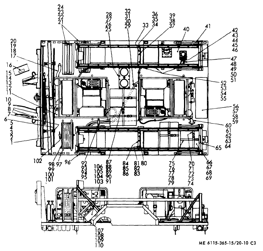
TM 5-6115-365-15
C3
Figure 20-10. PU-631/G power unit.
20-38
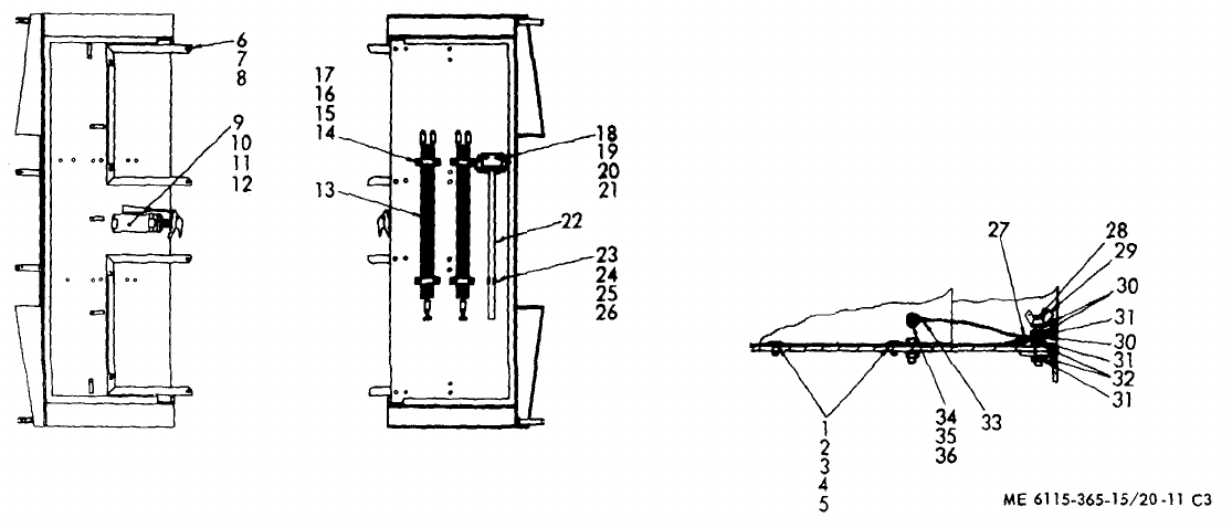
TM 5-6115-365-15
C3
Figure 20-11. PU-631/G accessories.
20-39
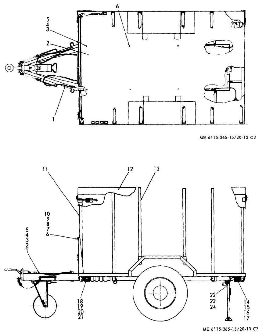
TM 5-6115-365-15
C3
Figure 20-12. Trailer body.
Figure 20-13. Trailer accessories.
20-40
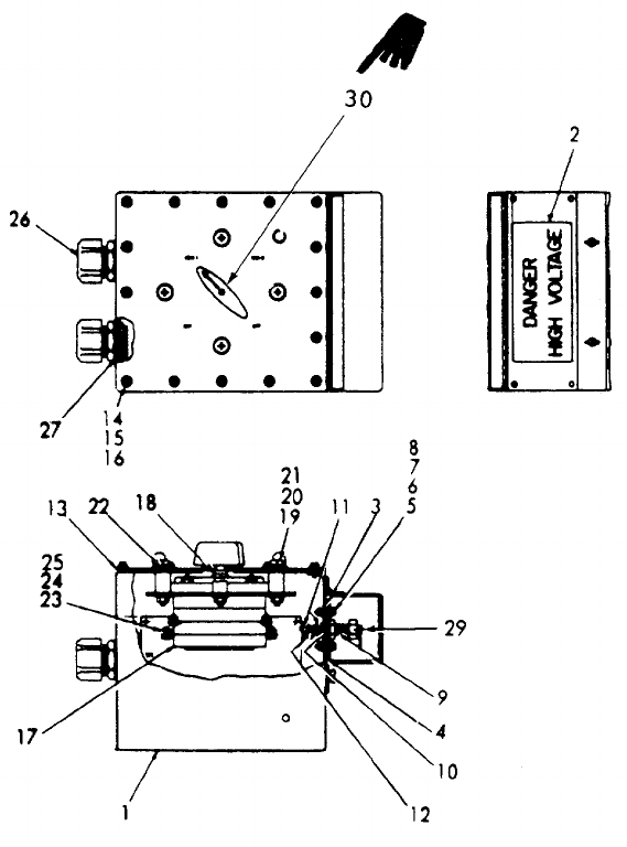
TM 5-6115-365-15
Figure 20-14. Distribution box.
Change 10 20-41
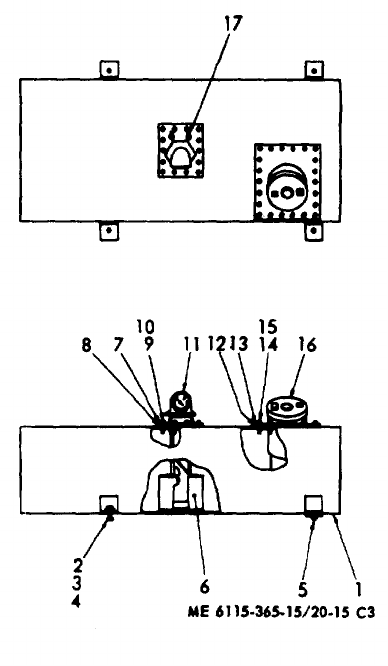
TM 5-6115-365-15
C3
Figure 20-15. Fuel tank.
20-42
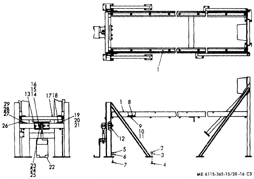
TM 5-6115-365-15
C3
Figure 20-16. Roadside rack assembly.
20-43
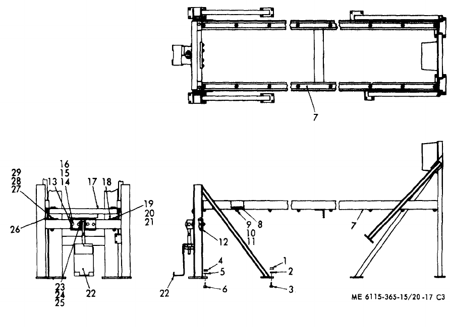
TM 5-6115-365-15
C3
Figure 20-17. Curbside rack assembly.
20-44
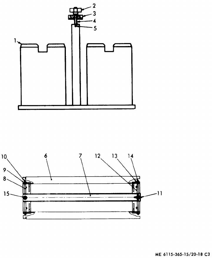
TM 5-6115-365-15
C3
Figure 20-18. Holder assemblies.
20-45
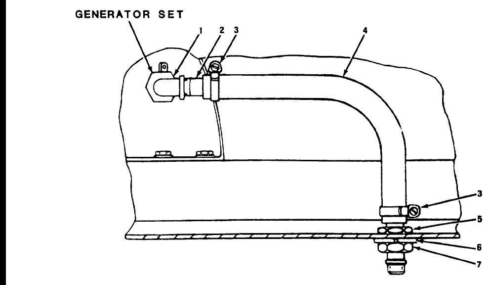
TM 5-6115-365-15
Figure 20-19. Oil drain assembly.
20-46 Change 8
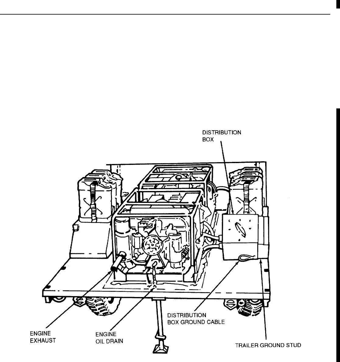
TM 5-6115-365-15
CHAPTER 21
GENERATOR SET, PU-656/G, NSN 6115-00-989-3296
Section I. DESCRIPTION AND DATA
21-1. Description
a. General. The trailer mounted generator set, PU-
656/G, consists of two 10 kW, DOD Model MEP-023A
generator sets mounted on a 1 1/2 ton, 2-wheel cargo
trailer, Model M103-A3.
b. Generators. The generators are powered by
direct drive 4-cylinder, air-cooled, 20-hp, Military
Standard Model 4A084 gasoline engines. For
description and generator operation and maintenance,
refer to TM 5-6115-450-15.
c. Engines. For description and engine
maintenance information, refer to TM 5-2805-259-14.
d. Trailer. For description and maintenance of the
trailer, refer to TM 9-2330-213-14.
e. Lubrication. For lubrication of the engine, refer
to LO 5-2805-259-12. The trailer lubrication information
is contained in LO 9-2330-213-12.
Figure 21-1. Generator set, PU-656/G
Change 10 21-1

TM 5-6115-365-15
21-2. Tabulated Data
Table 21-1 lists components for the PU-656/G Generator
Set.
Table 21-1. PU-656/G Components
FSN Qty Nomenclature
6110-913-9276 1Distribution box
6115-926-0843 2Generator, 10 kW, 400 hz,
MEP-023A
5975-878-3791 2Ground rod, w/attachments
5120-251-4489 1Sledge hammer
2540-914-2558 1Tarpaulin
2330-141-8052 1Trailer, M103-A3, 1-1/2 ton
21-2.1. General
a. Maintenance Forms and Records. Every
mission begins and ends with the paperwork. There isn't
much of it, but you have to keep it up. The forms and
records you fill out have several uses; they are a
permanent record of the services, repairs, and
modifications made on your equipment; they are reports
to Organizational Maintenance and to your Commander;
and they are a checklist for you when you want to know
what is wrong with the equipment after its last use, and
whether those faults have been fixed. For information
you need on forms and records, see: DA Pamphlet 738-
750.
b. Preventive Maintenance Checks and Services.
(See Table 21-2)
(1) Do your before (B) PREVENTIVE
MAINTENANCE just before you operate your
equipment. Pay attention to the CAUTIONS and
WARNINGS.
(2) Do your during (D) PREVENTIVE
MAINTENANCE while the equipment and/or its
component systems are in operation.
(3) Do your after (A) PREVENTIVE
MAINTENANCE right after operating the equipment.
Pay attention to the CAUTIONS and WARNINGS.
(4) Do your weekly (W) PREVENTIVE
MAINTENANCE weekly.
(5) Do your monthly (M) PREVENTIVE
MAINTENANCE once a month.
(6) If something doesn't work, troubleshoot it
with the instructions in the appropriate TM and notify
your supervisor.
(7) Always do your PREVENTIVE
MAINTENANCE in the same order until it gets to be a
habit. Once you've had some practice, you'll spot
anything wrong in a hurry.
(8) If anything looks wrong and you can't fix it,
write it on your DA Form 2404. If you find something
seriously wrong, report it to Organizational Maintenance
RIGHT NOW.
(9) When you do your PREVENTIVE
MAINTENANCE, take along the tools you need to make
all the checks. You always need a rag or two, also.
21-2.2. General Maintenance Procedures
a. Cleanliness. Dirt, grease, oil, and debris only
get in the way and may cover up a serious problem.
Clean as you work and as needed. Use dry cleaning
solvent Type II, Fed. Spec PD-680, on all metal
surfaces.
WARNING
Dry cleaning solvent, Type II, Fed.
Spec PD-680, is potentially
dangerous to personnel and
property. Do not use near open
flame or excessive heat. Flash point
of solvent is 139°°F (59.4°°C).
b. Bolts, Nuts, and Screws. Check them all for
obvious looseness, missing, bent, or broken condition.
You can't try them all with a tool, of course, but look for
chipped paint, bare metal, or rust around bolt heads. If
you find one you think is loose, tighten it, or report it to
Organizational Maintenance.
c. Welds. Look for loose or chipped paint, rust, or
gaps where parts are welded together. If you find a bad
weld, report it to Organizational Maintenance.
d. Electric Wires and Connectors. Look for
cracked or broken insulation, bare wires, and loose or
broken connectors. Check for loose connectors and
make sure the wires are in good shape. Report loose
connectors and bad wires to organizational
maintenance.
21-2 Change 10
Item Interval
Item to be Inspected
Procedure: Check for and have
repaired, filled, or adjusted Equipment is not
Ready/available
No. BDAWMas needed if:
TM 5-6115-365-15
e. Hydraulic Lines and Fittings. Look for wear,
damage, leaks, and make sure clamps and fittings are
tight. Wet spots show leaks, of course, but a stain
around a fitting or connector can mean a leak. If a leak
comes from a loose fitting or connector, report it to
Organizational Maintenance. If something is broken or
worn out, report it to Organizational Maintenance.
21-2.3. Fluid Leakage
It is necessary for you to know how fluid leakage affects
the status of the fuel, lubricating, coolant, and hydraulic
systems. The following are definitions of the
types/classes of leakage you need to know to be able to
determine the status of your equipment. Learn, then be
familiar with them and REMEMBER --WHEN IN DOUBT,
NOTIFY YOUR SUPERVISOR!
CAUTION
Equipment operation is allowable
with minor leakages (Class I or II)
except fuel.
Of course, consideration must be
given to the fluid capacity in the
item/system being
checked/inspected. When in doubt,
notify your supervisor.
When operating with Class I or II
leaks, check fluid levels more often
than required in your PMCS.
Class III leaks should be reported to
your supervisor or to Organizational
Maintenance.
a. Class I. Seepage of fluid (as indicated by
wetness or discoloration) not great enough to form
drops.
b. Class II. Leakage of fluid great enough to form
drops but not enough to cause drops to drip from item
being checked/inspected.
c. Class III. Leakage of fluid great enough to form
drops that fall from the item being checked/inspected.
Table 21-2. Operator/Crew Preventive Maintenance Checks and Services
NOTE:
These checks are to be made in the order listed, within designated interval.
B - Before operation A - After operation M - Monthly
D - During operation W - Weekly
1GENERATOR SET
•a. Check for proper ground connection. Generator set is not
properly grounded.
•b. Remove canvas cover from generator set, if
provided.
2CONTROLS AND INSTRUMENTS
•a. CURRENT INDICATOR METER No indication when
Indicates percent of applied load, not to exceed load is applied.
100%. Rotate ammeter phase selector switch to
monitor load applied to each phase.
•b. BATTERY CHARGING AMMETER Ammeter indicates
Indicates on + side of scale during normal a discharge.
operation.
Change 10 21-2.1
Item Interval
Item to be Inspected
Procedure: Check for and have
repaired, filled, or adjusted Equipment is not
Ready/available
No. BDAWMas needed if:
TM 5-6115-365-15
Table 21-2. Operator/Crew Preventive Maintenance Checks and Services (cont.)
NOTE
These checks are to be made in the order listed, within designated interval.
B - Before operation A - After operation M - Monthly
D - During operation W - Weekly
2•c. OIL PRESSURE GAGE Oil pressure below
(cont) Normal reading is 20 to 60 PSI (1.406 to 4.218 20 psi.
Kg/sq cm).
•d. AC VOLTMETER Voltage cannot be
Indicates output voltage. Adjust for desired adjusted.
voltage. Change voltage selector switch to mon-
itor the voltage for each phase combination. Desired voltage can-
not be obtained and
maintained.
•e. FREQUENCY METER
Indicates generator frequency. Meter does not indi-
Normal Readings: cate the proper fre-
MEP-018A, 60 HZ (red line) quency.
MEP-023A, 400 HZ (red line)
•f. INSIDE INSTRUMENT PANEL Faulty wiring or
Check for loose wiring, corroded wiring, and improper mounting
loose electrical components. of electrical compo-
nents.
•g. FIRE EXTINGUISHER
Check for damaged or broken seal or contents Extinguisher seal
indicator. broken or contents
indicator shows less
than fully charged.
3•BATTERIES
Insure connections are tight, not corroded, and Battery missing or
wires are not frayed or damaged. Check for will not crank
leaks. engine.
21-2.2 Change 10
Item Interval
Item to be Inspected
Procedure: Check for and have
repaired, filled, or adjusted Equipment is not
Ready/available
No. BDAWMas needed if:
TM 5-6115-365-15
Table 21-2. Operator/Crew Preventive Maintenance Checks and Services (cont.)
NOTE
These checks are to be made in the order listed, within designated interval.
B - Before operation A - After operation M - Monthly
D - During operation W - Weekly
4FUEL CAN
WARNING
Do not fill fuel can while smoking or in vicinity
of an open flame, provide a metal-to-metal
contact between the container and the fuel can
to prevent a spark from being generated as fuel
flows over metallic surfaces. Failure to observe
this may result in death to personnel.
Do not fill the fuel can while the engine is run-
ning. Gasoline spilled on a hot engine may
ignite.
•Add fuel as required to maintain operation. Do
not overfill. Fill can after operation to mini-
mize condensation in fuel can, and ready unit
for next day's operation.
Ensure generator set has cooled off before
installing canvas cover.
5••• ENGINE
Inspect the engine for loose or missing wiring, Class III oil leak or
parts, and for any oil or fuel leaks. ANY fuel leak.
6• • OIL LEAK
Check oil level. Add oil as required. Below add or above
full mark.
7• • • FUEL FILTER
Inspect fuel filter for dirt, water, or sediment.
*Clean
Change 10 21-2.3
Item Interval
Item to be Inspected
Procedure: Check for and have
repaired, filled, or adjusted Equipment is not
Ready/available
No. BDAWMas needed if:
TM 5-6115-365-15
Table 21-2. Operator/Crew Preventive Maintenance Checks and Services (cont.)
NOTE
These checks are to be made in the order listed, within designated interval.
B - Before operation A - After operation M - Monthly
D - During operation W - Weekly
8• • AIR CLEANER
Inspect for obstructions and clean if necessary. Restriction indica-
tor shows fully red
NOTE or element is torn,
dented, or damaged.
When restriction indicator shows fully red,
remove element from body and clean element
with low pressure compressed air. If element is
torn, dented, or damaged, replace element.
9WHEELS AND TIRES
WARNING
Improperly seated lockring could blow off.
Never attempt to seat a lockring when tire is
inflated. Serious injury or loss of life could
result.
• • a. check for proper mounting of wheel assem- Lockring is improp-
bly lockring. erly mounted.
•b. Remove any glass, nails, or other debris
imbedded in tread.
•c. Check tires for obvious damage such as cuts, One tire is flat,
bruises, bulges, and flats.missing, or unser-
viceable.
•d. Check tire pressure according to table Tire will not hold
below. air pressure.
Tire size 11:00-20 9:00-20
Highway 45 psi 50 psi
Cross country 25 psi 35 psi
Sand 20 psi 25 psi
21-2.4 Change 10
Item Interval
Item to be Inspected
Procedure: Check for and have
repaired, filled, or adjusted Equipment is not
ready/available
No. BDAWMas needed if:
TM 5-6115-365-15
Table 21-2. Operator/Crew Preventive Maintenance Checks and Services (cont.)
NOTE: These checks are to be made in the order listed, within designated interval.
B - Before operation A - After operation M - Monthly
D - During operation W - Weekly
10 FRAME SUSPENSION
•Check for cracks or broken welds. Cracked or has a
broken weld.
11 LIGHTS AND REFLECTORS
•Check for obvious damage or looseness of Lights or reflectors
lights, lenses, and reflectors. Check for proper are damaged or
operation. missing.
12 BODY, CARGO, M105 SERIES
•a. Check that stake racks and roof bows are
properly installed and not broken or damaged.
• • b. Check to see that paulin is not torn or dam-
aged and is properly tied down.
13 LANDING LEG
•Check for proper mounting, alinement, and Landing leg is
general condition. seized, damaged, or
missing.
14 INTERVEHICULAR CABLE
• • Check for general condition of cable and plug. Intervehicular cable
is broken or missing
15 BRAKE SYSTEM
• • a. Check for leakage of brake fluid from master Brake system has
cylinder, hydraulic brake lines, fittings, and any leak.
brake fluid reservoir.
• • b. Check air lines, hoses, fittings, filters, and Any leaks detected.
brake air chamber for leaks and general condi-
tions.
Change 10 21-2.5
Item Interval
Item to be Inspected
Procedure: Check for and have
repaired, filled, or adjusted Equipment is not
ready/available
No. BDAWMas needed if:
TM 5-6115-365-15
Table 21-2. Operator/Crew Preventive Maintenance Checks and Services (cont.)
NOTE: These checks are to be made in the order listed, within designated interval.
B - Before operation A - After operation M - Monthly
D - During operation W - Weekly
15 •c. Check for proper operation of handbrake. Handbrakes cannot
cont be adjusted.
•d. Check for proper operation of service Brakes do not oper-
brakes. ate properly.
WARNING
Feel brake drums and hubs cautiously. Brake
drums and hubs may be very hot. Failure to do
so may cause injury to personnel.
•e. Feel for overheated brake drum or hub. Brake drum or hub
is excessively hot.
Section II. OPERATING INSTRUCTIONS
21-3. Setting-Up Instructions
a. Leveling.
(1) Locate the trailer on as level a surface as
possible for the generators to operate efficiently.
(2) Set hand brakes and block wheels
securely to prevent any movement. Operate hand brake
at weekly intervals to insure freedom of movement.
(3) Lower leg prop and adjust length for firm
contact with ground.
WARNING
Wheels must be blocked, brakes set,
and leg prop down in support
position before attempting to roll up
tarpaulin and before starting to
assemble or set-up equipment for
operation.
b. Preparation for Starting.
(1) Remove canvas tarpaulin, roof bows, and
splash shield.
(2) Remove all loose auxiliary items that
might block flow of air through the trailer and around the
generator sets.
CAUTION
It is of utmost importance that there
be free circulation of air around the
generator sets at all times.
(3) Remove the pipe plugs from the engine oil
drains and install the drain hoses as illustrated on figures
21-1 and 21-2. Be sure the drain cocks are closed.
(4) Install the engine exhausts as illustrated in
figures 21-1 and 21-2.
(5) Install the engine spark plugs as
described in TM 5-2805-259-14.
(6) Connect the electrical leads from the
distribution box to the generator sets as illustrated on
figure 21-3.
21-2.6 Change 10
TM 5-6115-365-15
c. Grounding.
WARNING
Never operate generator sets until
they are properly grounded.
Electrical defects in the load lines
can cause death by electrocution.
(1) The ground may be any of three methods,
depending on the location and terrain.
(a) A ground rod driven to a depth of 8
feet.
(b) An underground metallic water
piping system.
(c) A metal plate (9 square ft.) buried to
a depth of 4 feet.
(2) The ground lead must be No. 6 AWG
copper wire clamped or bolted to the rod, plate, or piping
system.
(3) Connect the other end of the ground lead
to the trailer ground terminal.
(4) Connect the ground lead from the
distribution box to the trailer ground terminal.
d. Servicing. Service the generators as described
in TM 5-6115-450-15.
Change 10 21-2.7/(21-2.8 blank)
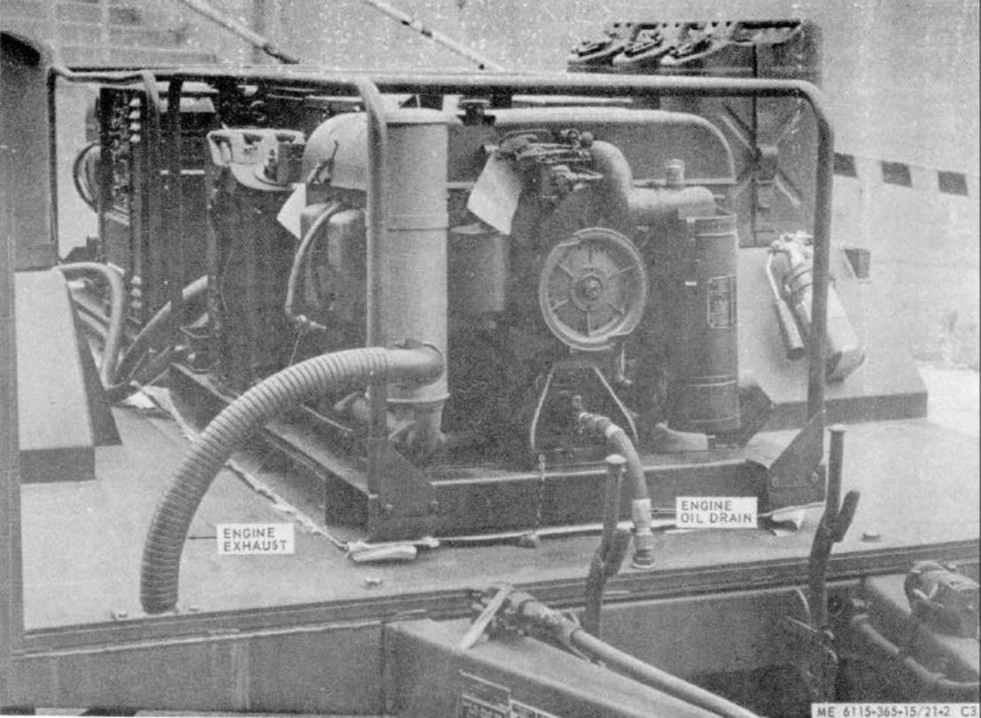
TM 5-6115-365-15
C3
Figure 21-2. Engine accessories, Installed view.
21-3
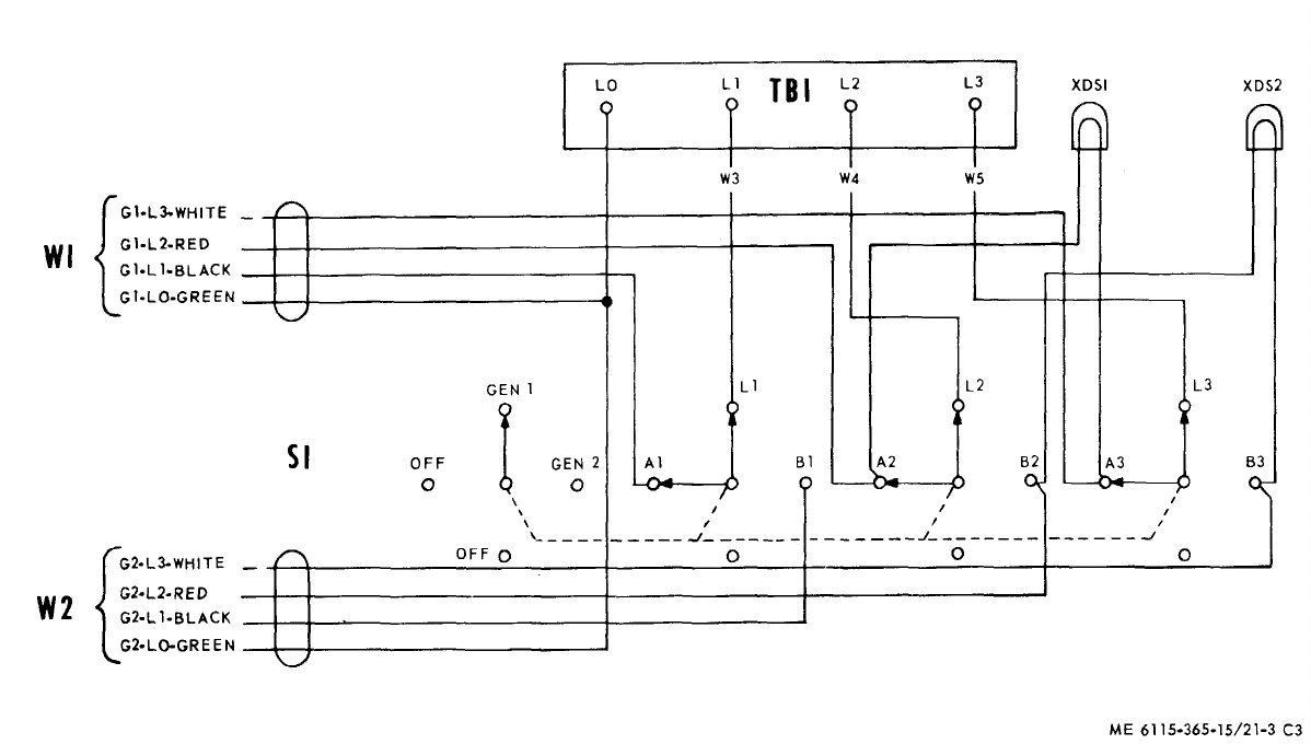
TM 5-6115-365-15
C3
Figure 21-3. Wiring diagram.
21-4
TM 5-6115-365-15
C3
21-4. Starting WARNING
Never operate the generator set in an
enclosed area unless exhaust gases
are piped outside. Inhalation of
exhaust fumes may result in serious
illness or death.
a. Perform the pre-starting operations in TM
5-6115-450-15.
b. Position the transfer switch to the desired
generator.
c. Start the generator as prescribed in TM
5-6115-450-15.
21-5. Stopping.
Stop the generator as described in TM 5-6115-450-15.
21-6. Operation
Operate the generator set as instructed in TM
5-6115-450-15. Use the fuel transfer valve to perform
fuel transfer operations from the set mounted 5-gallon
can to the remote cans.
Section III. OPERATOR'S MAINTENANCE INSTRUCTIONS
Operator's maintenance of the power unit is concerned
with keeping the generator sets lubricated; the fuel cans
filled; the battery electrolyte level maintained; and
cleaning and servicing the fuel filters and air cleaners as
described in TM 5-6115-450-15. Removal of dust and
dirt from the equipment is also a routine maintenance
function of the operator.
Section IV. ORGANIZATIONAL MAINTENANCE INSTRUCTIONS
21-7. Tarpaulin and Roof Bows
a. Removal.
(1) Remove tarpaulin from unit.
(2) Pull out chain-secured pins that secure
roof bows to trailer and remove bows.
b. Cleaning and Inspection.
(1) Clean tarpaulin and bows with water and
detergent. Dry thoroughly.
(2) Inspect tarpaulin for tears, holes, broken
or missing ropes and straps, and other defects. Inspect
bows for cracks, bends, or other defects.
c. Installation. Installation is reverse of procedure
a above. Be sure tarpaulin is treated for waterproofing
and mildew resistance before reinstalling.
21-8. Transfer Switch Indicating Lamp Replacement
Unscrew defective lamp from switch box and remove
gasket. Install gasket on replacement lamp and screw
into base socket in distribution box.
Section V. DIRECT AND GENERAL SUPPORT AND DEPOT
MAINTENANCE INSTRUCTIONS
21-9. Generator Set
a. Removal.
(1) Disconnect remote fuel line at three-way
valve.
(2) Disconnect electrical leads and load
cables.
(3) Disconnect oil drain adapter.
(4) Remove the battery.
(5) Disconnect the exhaust pipe (front engine
only).
(6) Remove nuts, washers, and capscrews
that secure generator set to trailer body and remove
generator set.
b. Installation. Installation is reverse of removal,
procedure a above. Make sure that the beveled
washers are properly positioned so that generator set is
securely mounted to the trailer body.
21-5
TM 5-6115-365-15
C3
21-10. Distribution Box
a. Removal.
(1) Disconnect load lines from the generators
and loosen cable clamps so that cables will be removed
with distribution box.
(2) Disconnect ground wire to trailer terminal
stud.
(3) Remove nuts and washers that secure
distribution box to trailer fender and remove box and
cables.
b. Disassembly. Refer to figure 21-4 and
disassemble the distribution box components. Tag the
cable ends for proper reassembly.
c. Reassembly. Reassembly is reverse of
disassembly procedure b above. Make sure "O" rings
are properly installed to prevent water entering around
the switch and screws.
d. Installation. Installation is reverse of removal
procedure a above. Refer to figure 21-3 to assure that
electrical load cables are properly connected.
21-11. Trailer Body
a. Removal.
(1) Remove tarpaulin and bows.
(2) Remove fuel cans and holders.
(3) Disconnect exhaust line and remove
generators (para 3-9).
(4) Remove distribution box (para 3-10).
(5) Remove nuts, washers, and bolts, and
capscrews that secure trailer body to chassis and
remove body.
b. Installation. Using a serviceable trailer body,
reverse removal procedure a above. Apply touch-up
paint to securing hardware after complete reassembly.
21-6
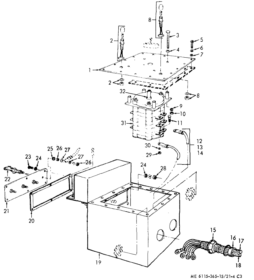
TM 5-6115-365-15
C3
LEGEND
ITEM FUNCT ITEM
NO. GROUP NAME
1 4206 COVER
2 4206 LIGHT-WIRE
3 4206 SCREW
4 4206 PACKING
5 2210 SCREW
6 2210 WASHER
7 2210 WASHER
8 4206 LIGHT-WIRE
9 4206 WASHER
10 4206 NUT
11 4206 SCREW
12 4206 LEAD
13 4206 LEAD
14 4206 LEAD
15 4206 PACKING
16 4206 STUFFING
17 4206 CABLE AY
18 4206 CABLE AY
19 4206 BOX
20 4206 GASKET
21 4206 TERMINAL BOARD
22 4206 CONNECTOR
23 4206 SCREW
24 4206 WASHER
25 4206 WASHER
26 4206 NUT
27 4206 WASHER
28 4206 NUT
29 4206 NUT
30 4206 WASHER
31 4206 SWITCH
32 4206 PACKING
Figure 21-4. Distribution box. 21-7

(1) (2) (3) (4) (5) (6) (7)
FEDERAL DESCRIPTION UNIT QTY 15-DAY ORGANIZATIONAL ILLUS-
SMR STOCK OF INC MAINTENANCE ALW RATION
CODE NUMBER USABLE MEAS IN (a) (b) (c) (d) (a) (b)
ON UNIT FIG ITEM
REF NUMBER & MFG CODE CODE 1-5 6-20 21-50 51-100 NO. NO.
TM 5-6115-365-15
C3
PART I - PU-656/G
00001 REPAIR PARTS FOR ORGANIZATIONAL MAINTENANCE
00002 GROUP 06 - ELECTRICAL SYSTEM
00003 0608 - MISCELLANEOUS TRAILER WIRING
X2 0CABLE ASSEMBLY, TAILLIGHT EA 221-6 32
00004 13216E7479 (97403)
X2 0LEAD, ELECTRICAL, TAILLIGHT EA 121-6 31
00005 13216E7476 (97403)
X2 0STRAP, CABLE: ADJUSTABLE PLASTIC TYPE EA 621-6 30
00006 MS17821-1-9 (96906)
00010 GROUP 18 - BODY
00011 1810 - CARGO BODY
X2 0BOLT, HEXAGON HEAD: 5/8-11 X 6 1/2 IN. IG EA 221-5 42
00013 FFB575TYPE3 (81348)
05305-724-5911 CAP SCREW, HEXAGON HEAD: EA 6****21-5 29
00014 5/8-11 X 1 3/4 IN. LG
MS90725-163 (96906)
05310-269-3211 CAP SCREW, HEXAGON READ: 3/8-16 X1 EA 16 ****21-5 41
00015 IN. LG
MS90725-60 (96906)
05310-269-4040 NUT, SELF-LOCKING: 5/8-11 UNC EA 8****21-5 27
00016 MS51922-49 (96906)
05310-087-4652 NUT, SELF-LOCKING: 3/8-16 UNC EA 12 ****21-5 38
00017 MS51922-17 (96906)
053104-823-8803 WASHER, FLAT: 5/8 IN. BSC SIZE EA 16 ****21-5 28
00019 MS27183-21 (96906)
05310-809-4061 WASHER, FLAT: 3/8 IN. BSC SIZE EA 28 ****21-5 40
00020 MS27183-15 (96906)
05310-637-9541 WASHER, LOCK: 3/8 IN. NOM. SIZE EA 4****21-5 39
00021 MS35338-46 (96906)
00022 GROUP 22 - BODY ACCESSORY ITEMS
00023 2201 - CANVAS ITEMS
POR 6115-459-5946 TARPAULIN EA 1***2
00024 13216E7434 (97403)
00025 2202 - ACCESSORY ITEMS
X2 02540-924-8478 BOW, TRAILER: 55 3/4 IN. EA 221-5 16
00026 13212E3597-2 (97403)
X2 02540-926-1003 BOW, TRAILER: 68 IN. EA 421-5 18
00027 13212E3597-1 (97403)
X2 02590-473-6331 BRACKET ASSEMBLY:LIQUID CONTAINER, 5 GAL EA 621-5 31
00028 MS53052-1 (96906)
X2 05340-999-6277 BRACKET ASSEMBLY: SLEDGE HAMMER MTG EA 121-5 24
00029 13214E1214 (97403)
X2 07240-222-3088 CAN, GASOLINE: MILITARY., 5 GAL EA 621-5 15
00030 MILC1283 (81349)
21-8

(1) (2) (3) (4) (5) (6) (7)
FEDERAL DESCRIPTION UNIT QTY 15-DAY ORGANIZATIONAL ILLUS-
SMR STOCK OF INC MAINTENANCE ALW RATION
CODE NUMBER USABLE MEAS IN (a) (b) (c) (d) (a) (b)
ON UNIT FIG ITEM
REF NUMBER & MFG CODE CODE 1-5 6-20 21-50 51-100 NO. NO.
TM 5-6115-365-15
C3
05305-269-3213 CAPSCREW, HEXAGON HEAD; EA 24 ****21-5 34
00031 3/8-16 X 1 1/4 IN LG
M590725-62 (96906)
05305-721-8010 CAPSCREW, HEXAGON HEAD:1/4-20 X 2 IN. LG EA 2****21- 46
00032 M35307-314 (96906)
05305-225-3839 CAPSCREW, HEXAGON HEAD:1/4-20 X 1 IN. LG EA 2****21-6 23
00033 MS90725-8 (96906)
05305-225-3839 CAPSCREW, HEXAGON HEAD: 1/4-20 X 1 IN. LG EA 1****21-6 29
00034 MS90725-8 (96906)
05305-068-0502 CAPSCREW, HEXAGON HEAD:1/4-20 X 3/4 IN. LG EA 8****21-5 10
00035 MS90725-6 (96906)
05305-068-0501 CAPSCREW, HEXAGON HEAD EA 12 ****21-6 5
00036 1/4-20 X 5/8 IN. LG
MS90725-5 (96906)
X2 0 2590-932-7298 CLAMP: GROUND ROD MTG EA 421-6 8
00037 13212E3617-1 (97403)
X2 05340-914-2578 CLIP, SPRING: SLEDGE HAMMER EA 121-6 26
00038 13214E1213-1 (97403)
00039
00040
05310-087-4652 NUT, SELF-LOCKING 3/8-16 UNC EA 24 ****21-5 32
00041 1551922-17 (96906)
05310-080-8495 NUT, PLAIN, WING 1/4-20 UNC EA 2****21-5 43
00042 MS35425-39 (96906)
05310-088-1251 NUT, SELF-LOCKING: 1/4-20 UNC EA 8****21-6 9
00043 MS51922-1 (96906)
05310-088-1251 NUT, SELF-LOCKING: 1/4-20 UNC EA 2****21-6 21
00044 MS51922-1 (96906)
05310-088-1251 NUT, SELF-LOCKING: 1/4-20 UNC EA 1****21-6 27
00045 MS51922-1 (96906)
05310-088-1251 NUT, SELF-LOCKING: 1/4-20 UNC EA 8****21-5 8
00046 MS51922-1 (96906)
05310-088-1251 NUT, SELF-LOCKING 1/4-20 UNC EA 12 ****21-6 3
00047 MS51922-1 (96906)
X2 PLATE, FRONT SHIELD 'EA 121-5 47
00048 13212E3611-1 (97403)
X2 09905-202-3639 REFLECTOR, CLEARANCE, AMER EA 221-6 6
00049 MS35387-2 (96906)
X2 09905-205-2795 REFLECTOR, CLEARANCE, RED EA 421-6 2
00050 MS35387-1 (96906)
00051
05305-958-5247 SCREW, MACHINE: 1/4-20 X 1 IN. EA 8****21-6 11
00052 MS35190-291 (96906)
05310-809-4061 WASHER, FLAT: 3/8 IN. BSC SIZE EA 24 ****21-5 33
00053 MS27183-15 (96906)
05310-809-4058 WASHER, FLAT: 1/4 IN. BSC SIZE EA 4****21-5 44
00054 MS27183-10 (96906)
05310-933-8121 WASHER, LOCK: 1/4 IN. NOM. SIZE EA 2****21-5 45
00055 MS35388-139 (96906)
21-9

(1) (2) (3) (4) (5) (6) (7)
FEDERAL DESCRIPTION UNIT QTY 15-DAY ORGANIZATIONAL ILLUS-
SMR STOCK OF INC MAINTENANCE ALW RATION
CODE NUMBER USABLE MEAS IN (a) (b) (c) (d) (a) (b)
ON UNIT FIG ITEM
REF NUMBER & MFG CODE CODE 1-5 6-20 21-50 51-100 NO. NO.
TM 5-6115-365-15
C3
05310-809-4058 WASHER, FLAT: 1/4 IN. BS SIZE EA 8****21-6 10
00056 MS27183-10 (96906)
05310-809-4058 WASHER, FLAT: 1/4 IN. BSC SIZE EA 4****21-6 22
00057 MS27183-10 (96906)
05310-809-4058 WASHER, FLAT: 1/4 IN. BSC SIZE EA 2****21-6 28
00058 MS27183-10 (96906)
05310-809-4058 WASHER, FLAT: 1/4 IN. BSC SIZE EA 16 ****21-5 9
00059 MS27183-10 (96906)
05310-809-4058 WASHER, FLAT: 1/4 IN. BSC SIZE EA 12 ****21-6 4
00060 MS27183-10 (96906)
00061 2210 - DATA PLATES
X2 0PLATE, IDENTIFICATION: GROUND TERMINAL EA 121-5 17
00062 13205E4918 (97403)
X2 0PLATE, IDENTIFICATION: PU-656/G EA 121-5 1
00063 13205E4916-17 (97403)
00064 GROUP 29 - AUXILIARY GENERATOR AND ENGINE
00070 2941 - ENGINE EXHAUST
05305-225-3839 SCREW, CAP, HEXAGON HEAD: EA 2****21-5 4
00071 1/4-20 X 1 IN. LG
MS90725-8 (96906)
X2 05340-917-6400 CLAMP ASSEMBLY EA 2****21-6 6
00072 13212E3592-4 (97403)
05310-088-1251 NUT, SELF-LOCKING: 1/4-20 UNC EA 2****21-5 2
00073 MS51922-1 (96906)
X2 0TUBE, EXHAUST, FRONT EA 121-5 5
00074 13216E7461 (97403)
X2 0TUBE, EXHAUST, REAR EA 121-5 26
00075 13214E1238 (97403)
05310-809-4058 WASHER, FLAT : 1/4 IN. BSC SIZE EA 4****21-5 3
00076 MS27183-10 (96906)
00077 GROUP 42 - ELECTRICAL EQUIPMENT
00078 4202 - ELECTRICAL CONTROL
X2 0LIGHT AND WIRE: 12 IN. LG EA 121-4 2
00090 13212E3581-1 (97403)
X2 0LIGHT AND WIRE: 17 IN. LG EA 121-4 8
00091 132125358 (97403)
00112 4216 - MISCELLANEOUS WIRING AND FITTINGS
05305-071-224 CAPSCEW, HEXAGON HEAD: EA 4****21-5 13
00113 1/4-20 X 1 1/4 IN. LG
MS90725-10 (96906)
05305-543-4718 CAPSCREW, HEXAGON HEAD: EA 1****21-6 12
00114 3/8-16 X 3/4 IN. LG
MS35309-358 (96906)
X2 0CLAMP, CABLE, DOUBLE EA 221-5 14
00115 13212E3591-5 (97403)
X2 05340-930-1754 CLAMP, LOOP, DOUBLE EA 221-5 24
00116 MS21334-2 (96906)
21-10

(1) (2) (3) (4) (5) (6) (7)
FEDERAL DESCRIPTION UNIT QTY 15-DAY ORGANIZATIONAL ILLUS-
SMR STOCK OF INC MAINTENANCE ALW RATION
CODE NUMBER USABLE MEAS IN (a) (b) (c) (d) (a) (b)
ON UNIT FIG ITEM
REF NUMBER & MFG CODE CODE 1-5 6-20 21-50 51-100 NO. NO.
TM 5-6115-365-15
C3
05310-918-6921 NUT, PLAIN, HEXAGON HEAD: EA 3****21-6 16
00117 3/8-16 THD SIZE
MS16203-39 (96906)
05310-543-4717 NUT, PLAIN, WING: BRASS, 3/8-16 UNC EA 1****21-6 14
00118 MS35425-28 (96906)
05310-088-1251 NUT, SELF-LOCKING: 1/4-20 UNC EA 4****21-5 13
00119 MS51922-1 (96906)
05310-934-9758 NUT, PLAIN, HEXAGON HEAD: NO. 10-24 UNC EA 2****21-5 20
00120 MS35649-202 (96906)
05310-918-6921 NUT, PLAIN, HEXAGON HEAD: 3/8-16 UNC EA 1****21-6 20
00121 MS16203-39 (96906)
05305-984-6211 SCREW, MACHINE, PAN HEAD:10-24 X 5/8 IN. LG EA 2****21-5 20
00122 MS35206-264 (96906)
X2 05307-722-9437 STUD, GROUNDING EA 121-6 17
00123 13214E1223 (97403)
05940-688-6010TERMINAL, LUG: CRIMP STYLE, NO. 6 AWG EA 4****21-6 19
00124 MS20659- 10 (96906)
05310-913-9776 WASHER, LOCK: 3/8 IN. NOM. SIZE EA 2****21-6 18
00125 MS35335-91 (96906)
X2 05310-187-2413 WASHER, FLAT: ELECTRICAL, 3/8 IN. BSC SIZE EA 421-6 15
00126 AN961-616T (88044)
05310-809-4058 WASHER, FLAT: 1/4 IN. BSC SIZE EA 8****21-5 12
00127 MS27183-10 (96906)
05310-045-3296 WASHER, LOCK: NO. 10 NOM SIZE EA 2****21-5 21
00128 MS35338-43 (96906)
05310-809-8546WASHER, FLAT: NO. 10 BSC SIZE EA 4****21-5 22
00129 MS27183-8 (96906)
05310-913-9776 WASHER, LOCK: 3/8 IN. NOM SIZE EA 1****21-6 13
00130 MS35335-91 (96906)
X2 06145-299-6188 WIRE, ELECTRICAL: NO. 6 AWG(AS REQUIRED) FT 21-5 19
00131 QQW343TYPERB (81348)
21-11

(1) (2) (3) (4) (5) (6) (7) (8) (9) (10)
DESCRIPTION 1-YR
DEPOT
QTY 30-DAY DS MAINT 30-DAY GS MAINT ALW
PER
MAINT
ALW ILLUS-
TRATION
FEDERAL USABLE
UNIT
INC ALLOWANCE ALLOWANCE 100 PER (a) (b)
SMR
CODE STOCK
NUMBER
ON
REF NUMBER & MFR CODE CODE OF
MEAS IN
UNIT (a)
1-20 (b)
21-50 (c)
51-100 (a)
1-20 (b)
21-50 (c)
51-100
EQUIP
CNTGCY 100
EQUIP
FIG.
NO.
ITEM
NO.
TM 5-6115-365-15
C3
PART II - PU-656/G
00001 REPAIR PARTS FOR DS, GS AND DEPOT
MAINTENANCE
00002 GROUP 06 - ELECTRICAL SYSTEM
00003 0608 - MISCELLANEOUS TRAILER WIRING
X2 0CABLE ASSEMBLY, TAILLIGHT EA 221-6 32
00004 13216E7479 (97403)
X2 0LEAD, ELECTRICAL, TAILLIGHT EA 121-6 31
00005 13216E7476 (97403)
X2 0STRAP, CABLE: ADJUSTABLE PLASTIC EA 621-6 30
00006 TYPE
MS17821-1-9 (96906)
00007 GROUP 15 - FRAME
00008 1501 - FRAME ASSEMBLY
X2 DR CHASSIS, TRAILER EA 121-6 1
00009 13212E3588-2 (97403)
00010 GROUP 18 - BODY
00011 1810 - CARGO BODY
X2 DR BODY, TRAILER EA 121-5 30
00012 13214E1495 (97403)
X2 0BOLT, HEXAGON HEAD:5/8-11 X 6 1/2
00013 IN. LG EA 221-5 42
FFB575TYPE3 (81348)
05305-724-5911 CAPSCREW, HEXAGON HEAD: EA 6******* *21-5 29
00014 5/8-11 X 1 3/4 IN. LG
MS90725-163 (96906)
05310-269-3211 CAPSCREW, HEXAGON HEAD: 3/9-16 X 1 EA 16 ******* *21-5 41
00015 IN. LG
MS90725-60 (96906)
05310-269-4040 NUT, SELF-LOCKING:5/8-11 UNC EA 8******* *21-5 27
00016 MS51922-49 (96906)
05310-087-4652 NUT, SELF-LOCKING:3/8-16 UNC EA 12 ******* *21-5 38
00017 MS51922-17 (96906)
X2D SHIM (AS REQUIRED) EA 21-5 48
00018 13212E3590 (97403)
05310-823-8803 WASHER, FLAT:5/8 IN. BSC SIZE EA 16 ******* *21-5 28
00019 MS27183-21 (96906)
05310-809-4061 WASHER, FLAT:3/8 IN. BSC SIZE EA 28 ******* *21-5 40
00020 MS27183-15 (96906)
05310-637-9541 WASHER, LOCK: 3/8 IN. NOM. SIZE EA 4******* *21-5 39
00021
MS35338-46 (96906)
00022 GROUP 22 - BODY ACCESSORY ITEMS
00023 2201 - CANVAS ITEMS
POR 6115-459-5946 TARPAULIN EA 1*2 2 *2 2 10 10
00024 13216E7434 (97403)
21-12
(1) (2) (3) (4) (5) (6) (7) (8) (9) (10)
DESCRIPTION 1-YR
DEPOT
QTY 30-DAY DS MAINT 30-DAY GS MAINT ALW
PER
MAINT
ALW ILLUS-
TRATION
FEDERAL USABLE
UNIT
INC ALLOWANCE ALLOWANCE 100 PER (a) (b)
SMR
CODE STOCK
NUMBER
ON
REF NUMBER & MFR CODE CODE OF
MEAS IN
UNIT (a)
1-20 (b)
21-50 (c)
51-100 (a)
1-20 (b)
21-50 (c)
51-100
EQUIP
CNTGCY 100
EQUIP
FIG.
NO.
ITEM
NO.
TM 5-6115-365-15
C3
00025 2202 - ACCESSORY ITEMS
X2 02540-924-8478 BOW, TRAILER: 55 3/4 IN. EA 221-5 16
00026 13212E3597-2 (97403)
X2 02540-926-1003 BOW, TRAILER: 68 IN. EA 421-5 18
00027 13212E3597-1 (97403)
X2 02590-473-6331 BRACKET ASSEMBLY: LIQUID CONTAINER, EA 621-5 31
00028 5 GAL
MS53052-1 (96906)
X2 05340-999-6277 BRACKET ASSEMBLY: SLEDGE HAMMER MTG EA 121-5 24
00029 13214E1214 (97403)
X2 07240-222-3088 CAN, GASOLINE:MILITARY, 5 GAL EA 621-5 15
00030 MILC1283 (8'349)
05305-269-3213 CAPSCREW, HEXAGON HEAD: EA 24 ******* *21-5 34
00031 3/8-16 X 1 1/4 IN. LG
MS90725-62 (96906)
05305-721-8010 CAPSCREW, HEXAGON HEAD: 1/4-20 X 2 EA 2******* *21-5 46
00032 IN. LG
MS35307-314 (96906)
05305-225-3839 CAPSCREW, HEXAGON HEAD EA 2******* *21-6 23
00033 1/4-20 X 1 IN. LG
MS90725-8 (96906)
05305-225-3839 CAPSCREW, HEXAGON HEAD: EA 1******* *21-6 29
00034 1/4-20 X 1 IN. LG
MS90725-8 (96906)
05305-068-0502 CAPSCREW, HEXAGON MEAD: EA 8******* *21-5 10
00035 1/4-20 X 3/4 IN. LG
MS90725-6 (96906)
05305-068-0501 CAPSCREW, HEXAGON HEAD: EA 12 ******* *21-6 5
00036 1/4-20 X 5/8 IN. LG
MS90725-5 (96906)
X2 02590-932-7298 CLAMP: GROUND ROD MTG EA 421-6 8
00037 13212E3617-1 (97403)
X2 05340-914-2578 CLIP, SPRING: SLEDGE HAMMER EA 121-6 26
00038 13214E1213-1 (97403)
00039
00040
05310-087-4652 NUT, SELF-LOCKING 3/8-16 UNC EA 24 ******* *21-5 32
00041 MS51922-17 (96906)
05310-080-8495 NUT, PLAIN, WING:1/4-20 UNC EA 2******* *21-5 43
00042 MS35425-39 (96906)
05310-088-1251 NUT, SELF-LOCKING:1/4-20 UNC EA 8******* *21-6 9
00043 MS51922-1 (96906)
05310-088-1251 NUT, SELF-LOCKING:1/4-20 UNC EA 2******* *21-6 21
00044 MS51922-1 (96906)
0 5310-088-1251 NUT, SELF-LOCKING:1/4-20 UNC EA 1******* *21-6 27
00045 MS51922-1 (96906)
00 5310-088-1251 NUT, SELF-LOCKING, 1/4-20 UNC EA 8******* *21-5 8
00046 MS51922-1 (96906)
05310-088-1251 NUT, SELF-LOCKING:1/4-20 UNC EA 12 ******* *21-6 3
00047 MS51922-1 (96906)
X2 0PLATE, FRONT SHIELD EA 121-5 47
00048 13212E3611-1 (97403)
X2 09905-202-3639 REFLECTOR, CLEARANCE, AMBER EA 221-6 6
00049 MS35387-2 (96906)
21-13

(1) (2) (3) (4) (5) (6) (7) (8) (9) (10)
DESCRIPTION 1-YR
DEPOT
QTY 30-DAY DS MAINT 30-DAY GS MAINT ALW
PER
MAINT
ALW ILLUS-
TRATION
FEDERAL USABLE
UNIT
INC ALLOWANCE ALLOWANCE 100 PER (a) (b)
SMR
CODE STOCK
NUMBER
ON
REF NUMBER & MFR CODE CODE OF
MEAS IN
UNIT (a)
1-20 (b)
21-50 (c)
51-100 (a)
1-20 (b)
21-50 (c)
51-100
EQUIP
CNTGCY 100
EQUIP
FIG.
NO.
ITEM
NO.
TM 5-6115-365-15
C3
X2 09905-205-2795 REFLECTOR, CLEARANCE, RED EA 421-6 2
00050 MS35387-1 (96906)
00051
05305-958-5247 SCREW, MACHINE:1/4-20 X 1 IN. LG EA 8******* *21-6 11
00052 MS35190-291 (96906)
05310-809-4061 WASHER, FLAT: 3/8 IN. BSC SIZE EA 24 ******* *21-5 33
00053 MS27183-15 (96906)
05310-809-4058 WASHER, FLAT:1/4 IN. BSC SIZE EA 4******* *21-5 44
00054 MS27183-10 (96906)
05310-933-8121 WASHER, LOCK:1/4 IN. NOM. SIZE, EA 2******* *21-5 45
00055
MS35388-139 (96906)
05310-809-4058 WASHER, FLAT:1/4 IN. BSC SIZE EA 8******* *21-6 10
00056 MS27183-10 (96906)
05310-809-4058 WASHER, FLAT: 1/4 IN. BSC SIZE EA 4******* *21-6 22
00057 MS27183-10 (96906)
05310-809-4058 WASHER, FLAT:1/4 IN. BSC SIZE EA 2******* *21-6 28
00058 MS27183-10 (96906)
05310-809-4058 WASHER, FLAT:1/4 IN. BSC SIZE EA 16 ******* *21-5 9
00059 MS27183-10 (96906)
05310-809-4058 WASHER, FLAT:1/4 IN. BSC SIZE EA 12 ******* *21-6 4
00060 MS27183-10 (96906)
00061 2210 - DATA PLATES
X2 0PLATE, IDENTIFICATION: GROUND TERMINAL EA 121-5 17
00062 13205E4918 (97403)
X2 0PLATE, IDENTIFICATION: PU-656/G EA 121-5 1
00063 13205E4916-17 (97403)
00064 GROUP 29 - AUXILIARY GENERATOR AND ENGINE
00065 2901 - GENERATOR AND ENGINE ASSEMBLY
F5305-724-5911 SCREW, CAP, HEXAGON HEAD: EA 8******* *21-5 37
00066 5/8-11 X 1 3/4 IN LG
MS90725-163 (96906)
X2 FR 6115-926-0843 GENERATOR SET:10KW, MEP-023A EA 221-5 25
00067 MILG52280TYPE2 (81349)
F5310-269-4040 NUT, SELF-LOCKING 5/8-11 UNC EA 8******* *21-5 35
00068 MS51922-49 (96906)
F5310-823-8803 WASHER, FLAT: 5/8 IN. BSC SIZE EA 16 ******* *21-5 36
00069 MS27183-21 (96906)
00070 2941 - ENGINE EXHAUST
05305-225-3839 SCREW, CAP, HEXAGON HEAD: EA 2******* *21-5 4
00071 1/4-20 X 1 IN. LG
MS90725-8 (96906)
X2 05340-917-6400 CLAMP ASSEMBLY EA 221-5 6
00072 13212E3592-4 (97403)
05310-088-1251 NUT, SELF-LOCKING: 1/4-20 UNC EA 2******* *21-5 2
00073 MS51922-1 (96906)
X2 0TUBE, EXHAUST, FRONT EA 121-5 5
00074 13216E7461 (97403)
21-14
(1) (2) (3) (4) (5) (6) (7) (8) (9) (10)
DESCRIPTION 1-YR
DEPOT
QTY 30-DAY DS MAINT 30-DAY GS MAINT ALW
PER
MAINT
ALW ILLUS-
TRATION
FEDERAL USABLE
UNIT
INC ALLOWANCE ALLOWANCE 100 PER (a) (b)
SMR
CODE STOCK
NUMBER
ON
REF NUMBER & MFR CODE CODE OF
MEAS IN
UNIT (a)
1-20 (b)
21-50 (c)
51-100 (a)
1-20 (b)
21-50 (c)
51-100
EQUIP
CNTGCY 100
EQUIP
FIG.
NO.
ITEM
NO.
TM 5-6115-365-15
C3
X2 0TUBE, EXHAUST, REAR EA 121-5 26
00075 13214E7238 (97403)
05310-809-4058 WASHER, FLAT:1/4 IN. BSC SIZE EA 4******* *21-5 3
00076 MS27183-10 (96906)
00077 GROUP 42 - ELECTRICAL EQUIPMENT
00078 4202 - ELECTRICAL CONTROL
PFR 6110-913-9276 DISTRIBUTION BOX EA 1******2 2 21-4
00079 13212E3577 (97403)
X2 HBOX EA 121-4 19
00080 13212E3578 (97403)
X2 H6115-948-7389 CABLE ASSEMBLY EA 121-4 17
00081 13212E3584-1 (97403)
X2 H6115-948-7390 CABLE ASSEMBLY EA 121-4 18
00082 13212E3585-1 (97403)
F5305-983-7467 CAPSCREW, SOCKET HEAD: EA 4******* *21-4 3
00083 1/2-13 X 3 IN. LG
MS16997-149 (96906)
X2 F5940-943-7740 CONNECTOR, TERMINAL POST EA 421-4 22
00084 13213E3949 (97403)
X2 FCOVER, DISTRIBUTION BOX EA 121-4 1
00085 13212E3579 (97403)
X2 FGASKET, TERMINAL BOARD EA 121-4 20
00086 13212E3583 (97403)
X2 HLEAD, ELECTRICAL EA 121-4 12
00087 13212E3586-1 (97403)
X2 HLEAD, ELECTRICAL EA 121-4 13
00088 13212E3586-2 (97403)
X2 HLEAD, ELECTRICAL EA 121-4 14
00089 13212E586-3 (97403)
X2 0LIGHT AND WIRE: 12 IN. LG EA 121-4 2
00090 13212E3581-1 (97403)
X2 0LIGHT AND WIRE: 17 IN. LG EA 121-4 8
00091 13212E3581 (97403)
F5310-225-6993 NUT, PLAIN, HEXAGON: JAM, EA 4******* *21-4 26
00092 1/2-13 THD SIZE
MS16203-41 (96906)
H5310-088-1251 NUT, SELF-LOCKING 1/4-20 THD SIZE EA 6* * * * * 21-4 28
00093 MS51922-1 (96906)
F5310-225-6993 NUT, SELF-LOCKING:1/2-13 THD SIZE EA 4******* *21-4 10
00094 MS51922-33 (96906)
H5310-222-0671 NUT, PLAIN, HEXAGON HEAD,: EA 9* * * * * 21-4 29
00095 BASS, 3/8-24 THD SIZE
MS20341-616A (96906)
X2 F5330-833-1428 PACKING, PREFORMED: O RING EA 221-4 15
00096 MS28775-142 (96906)
X2 F5330-579-7916 PACKING, PREFORMED EA 121-4 32
00097 MS28775-115 (96906)
F5330-618-5361 PACKING, PREFORMED: O RING EA 4******* *21-4 4
00098 MS28775-015 (96906)
H5305-988-1727 SCREW, MACHINE, PAN HEAD: EA 6* * * * * 21-4 23
00099 1/4-20 X 1 IN. LG
MS35206-283 (96906)
HSCREW, MACHINE, PAN HEAD: EA 121-4 11
00100 3/8-24 X 3/4 IN. IL
MS35215-95 (96906)
21-15
(1) (2) (3) (4) (5) (6) (7) (8) (9) (10)
DESCRIPTION 1-YR
DEPOT
QTY 30-DAY DS MAINT 30-DAY GS MAINT ALW
PER
MAINT
ALW ILLUS-
TRATION
FEDERAL USABLE
UNIT
INC ALLOWANCE ALLOWANCE 100 PER (a) (b)
SMR
CODE STOCK
NUMBER
ON
REF NUMBER & MFR CODE CODE OF
MEAS IN
UNIT (a)
1-20 (b)
21-50 (c)
51-100 (a)
1-20 (b)
21-50 (c)
51-100
EQUIP
CNTGCY 100
EQUIP
FIG.
NO.
ITEM
NO.
TM 5-6115-365-15
C3
F5305-989-7434 SCREW, MACHINE, PAN HEAD: EA 16 ******* *21-4 5
00101 10-32 X 1/2 IN. LG
MS35207-263 (96906)
PBFFF STUFFING TUBE EA 221-4 16
00102 13218E5149-10 (97403)
PFSWITCH, ROTARY: 200 AMP EA 1******2 2 21-4 31
00103 13205E5024 (97403)
X2 HTECHNICAL BOARD EA 121-4 21
00104 13211E4775 (97403)
F5310-042-4229 WASHER, LOCK: INTERNAL TOOTH, EA 4******* *21-4 25
00105 1/2 IN. NOM SIZE
MS35333-113 (96906)
FWASHER, FLAT: BRASS, 1/2 IN. EA 8******* *21-4 27
00106 SCREW SIZE
AN961-816T (88044)
H5310-809-4058 WASHER, FLAT: 1/4 IN. SCREW SIZE EA 12 * * * * * 21-4 24
00107 MS27183-10 (96906)
F5310-809-5998 WASHER, FLAT: 1/2 IN. BSC SIZE EA 8******* *21-4 9
00108 MS27183-18 (96906)
H5310-913-9776 WASHER, LOCK: EXTERNAL TOOTH, EA 9* * * * * 21-4 30
00109 3/8 IN. SCREW SIZE
MS35335-91 (96906)
F5310-045-3296 WASHER, LOCK: NO. 10 SCREW SIZE EA 16 ******* *21-4 6
00110 MS35338-43 (96906)
F5310-809-8546 WASHER, FLAT: NO. 10 SCREW SIZE EA 16 ******* *21-4 7
00111 MS27183-8 (96906)
00112 4216 - MISCELLANEOUS WIRING AND FITTINGS
05305-071-2242 CAPSCREW, HEXAGON HEAD: EA 4******* *21-5 13
00113 1/4-20 X 1 1/4 IN. LG
MS90725-10 (96906)
05305-543-4718 CAPSCREW, HEXAGON HEAD: EA 1******* *21-6 12
00114 3/8-16 X 3/4 IN. LG
MS35309-358 (96906)
X2 0CLAMP, CABLE, DOUBLE EA 221-5 14
00115 13212E3591-5 (97403)
X2 05340-930-1754 CLAMP, LOOP, DOUBLE EA 221-5 24
00116 MS21334-2 (96906)
05310-918-6921 NUT, PLAIN, HEXAGON HEAD: EA 3******* *21-6 16
00117 3/8-16 THD SIZE
MS16203-39 (96906)
05310-543-4717 NUT, PLAIN, WING: BRASS, EA 1******* *21-6 14
00118 3/8-16 UNC
MS35425-28 (96906)
05310-088-1251 NUT, SELF-LOCKING: 1/4-20 UNC EA 4******* *21-5 13
00119 MS51922-1 (96906)
05310-934-9758 NUT, PLAIN, HEXAGON HEAD: EA 2******* *21-5 20
00120 NO. 10-24 UNC
MS35649-202 (96906)
05310-918-6921 NUT, PLAIN, HEXAGON HEAD: EA 1******* *21-6 20
00121 3/8-16 UNC
MS16203-39 (96906)
05305-984-6211 SCREW, MACHINE, PAN HEAD: EA 2******* *21-5 20
00122 10-24 X 5/8 IN. LG
MS35206-264 (96906)
X2 05307-722-9437 STUD, GROUNDING EA 121-6 17
00123 13214E1223 (97403)
21-16 Change 8

(1) (2) (3) (4) (5) (6) (7) (8) (9) (10)
DESCRIPTION 1-YR
DEPOT
QTY 30-DAY DS MAINT 30-DAY GS MAINT ALW
PER
MAINT
ALW ILLUS-
TRATION
FEDERAL USABLE
UNIT
INC ALLOWANCE ALLOWANCE 100 PER (a) (b)
SMR
CODE STOCK
NUMBER
ON
REF NUMBER & MFR CODE CODE OF
MEAS IN
UNIT (a)
1-20 (b)
21-50 (c)
51-100 (a)
1-20 (b)
21-50 (c)
51-100
EQUIP
CNTGCY 100
EQUIP
FIG.
NO.
ITEM
NO.
TM 5-6115-365-15
C3
05940-688-6010 TERMINAL, LUG: CRIMP STILE, EA 4******* *21-6 19
00124 NO. 6 AWG
MS20659- 10 (96906)
05310-913-9776 WASHER, LOCK:3/8 IN. NOM. SIZE EA 2******* *21-6 18
00125
MS35335-91 (96906)
X2 05310-187-2413 WASHER, FLAT: ELECTRICAL, 3/8 IN. EA 421-6 15
00126 BSC SIZE
AN961-616T (88044)
05310-809-4058 WASHER, FLAT:1/4 IN. BSC SIZE EA 8******* *21-5 12
00127 MS27183-10 (96906)
05310-045-3296 WASHER, LOCK: NO. 10 NOM. SIZE EA 2******* *21-5 21
00128
MS35338-43 (96906)
05310-809-8546 WASHER, FLAT: NO. 10 BSC SIZE EA 4******* *21-5 22
00129 MS27183-8 (96906)
05310-913-9776 WASHER, LOCK: 3/8 IN. NOM. SIZE EA 1 * ****** *21-6 13
00130
MS35335-91 (96906)
X2 06145-299-6188 WIRE, ELECTRICAL: NO. 6 AWG FT 21-5 19
00131 (AS REQUIRED)
QQW343TYPERB (81348)
21-17
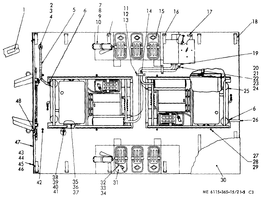
TM 5-6115-365-15
C3
Figure 21-5. PU-656/G power unit.
21-18
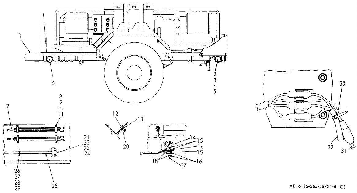
TM 5-6115-365-15
C3
Figure 21-6. PU-656/G accessories.
21-19
TM 5-6115-365-15
CHAPTER 22
GENERATOR SET PU-625/G, NSN 6115-00-837-3915
Section I. DESCRIPTION AND DATA
22-1. Description
a. General. The trailer mounted generator set, PU-
625/G, consists of two 3 kW, 60 hz, MEP-016C Military
Design generator sets mounted on a modified 3/4 ton, 2-
wheel cargo trailer, model M-101-A1. (Figures 22-1 and
22-2.) Brackets, racks, holders, and cable reels are
provided for transporting and installing communications
equipment. Table 22-1 lists components of the PU-
625/G generator set.
b. Generators. Each MEP-016C 3 kW generator
set is powered by a directly coupled 4-cylinder, 6 hp,
military standard model 4A0323 gasoline engine. For
description, operation, and maintenance of the
generators, refer to TM 5-6115-271-14. A power
transfer switch is provided for connecting the generators
to a common load.
c. Engines. For description, operation, and
maintenance information not covered in TM
5-6115-271-14, refer to TM 5-2805-203-14.
d. Trailer. For description and maintenance of the
trailer chassis, refer to TM 9-2330-202-14.
22-2. Tabulated Data
Table 22-1 lists components for PU-625/G generator set.
Table 22-1. PU-625/G Components
NSN Qty Nomenclature
6110-00-400-7592 1Distribution box
4210-00-270-4512 1Fire extinguisher, 5 lb.
6115-01-143-3311 2Generator, 3 kW, 60 hz,
MEP-016C
5975-00-878-3791 2Ground rod, 9 ft.
5120-00-251-4489 1Sledge hammer
2540-00-513-9794 1Tarpaulin
2330-00-898-6779 1Trailer M-101-A1, 3/4 ton
22-2.1. General
a. Maintenance Forms and Records. Every
mission begins and ends with the paperwork. There isn't
much of it, but you have to keep it up. The forms and
records you fill out have several uses; they are a
permanent record of the services, repairs, and
modifications made on your equipment; they are reports
to Organizational Maintenance and to your Commander;
and they are a checklist for you when you want to know
what is wrong with the equipment after its last use, and
whether those faults have been fixed. For information
you need on forms and records, see: DA Pamphlet 738-
750.
b. Preventive Maintenance Checks and Services.
(See Table 22-2)
(1) Do your before (B) PREVENTIVE
MAINTENANCE just before you operate your
equipment. Pay attention to the CAUTIONS and
WARNINGS.
(2) Do your during (D) PREVENTIVE
MAINTENANCE while the equipment and/or its
component systems are in operation.
(3) Do your after (A) PREVENTIVE
MAINTENANCE right after operating the equipment.
Pay attention to the CAUTIONS and WARNINGS.
(4) Do your weekly (W) PREVENTIVE
MAINTENANCE weekly.
(5) Do your monthly (M) PREVENTIVE
MAINTENANCE once a month.
(6) If something doesn't work, troubleshoot it
with the instructions in the appropriate TM and notify
your supervisor.
(7) Always do your PREVENTIVE
MAINTENANCE in the same order until it gets to be a
habit. Once you've had some practice, you'll spot
anything wrong in a hurry.
Change 10 22-1
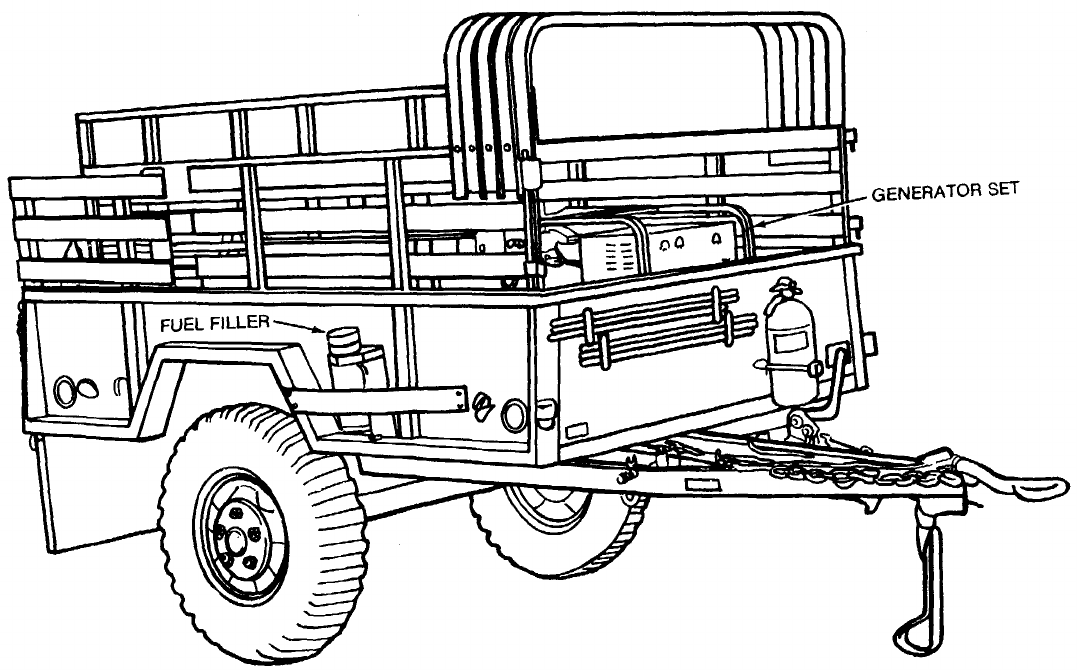
TM 5-6115-365-15
Figure 22-1. Generator set, PU-625/G.
22-2 Change 10

TM 5-6115-365-15
(8) If anything looks wrong and you can't fix it,
write it on your DA Form 2404. If you find something
seriously wrong, report it to Organizational Maintenance
RIGHT NOW.
(9) When you do your PREVENTIVE
MAINTENANCE, take along the tools you need to make
all the checks. You always need a rag or two, also.
22-2.2. General Maintenance Procedures
a. Cleanliness. Dirt, grease, oil, and debris only
get in the way and may cover up a serious problem.
Clean as you work and as needed. Use dry cleaning
solvent Type II, Fed. Spec PD-680, on all metal
surfaces.
WARNING
Dry cleaning solvent, Type II, Fed.
Spec PD-680, is potentially
dangerous to personnel and
property. Do not use near open
flame or excessive heat. Flash point
of solvent is 139°F (59.4°C).
b. Bolts, Nuts, and Screws. Check them all for
obvious looseness, missing, bent, or broken condition.
You can't try them all with a tool, of course, but look for
chipped paint, bare metal, or rust around bolt heads. If
you find one you think is loose, tighten it, or report it to
Organizational Maintenance.
c. Welds. Look for loose or chipped paint, rust, or
gaps where parts are welded together. If you find a bad
weld, report it to Organizational Maintenance.
d. Electric Wires and Connectors. Look for
cracked or broken insulation, bare wires, and loose or
broken connectors. Check for loose connectors and
make sure the wires are in good shape. Report loose
connectors and bad wires to organizational
maintenance.
e. Hydraulic Lines and Fittings. Look for wear,
damage, leaks, and make sure clamps and fittings are
tight. Wet spots show leaks, of course, but a stain
around a fitting or connector can mean a leak. If a leak
comes from a loose fitting or connector, report it to
Organizational Maintenance. If something is broken or
worn out, report it to Organizational Maintenance.
22-2.3. Fluid Leakage
It is necessary for you to know how fluid leakage affects
the status of the fuel, lubricating, coolant, and hydraulic
systems. The following are definitions of the
types/classes of leakage you need to know to be able to
determine the status of your equipment. Learn, then be
familiar with them and REMEMBER WHEN IN DOUBT,
NOTIFY YOUR SUPERVISOR!
CAUTION
Equipment operation is allowable
with minor leakages (Class I or II)
except fuel. Of course, consideration
must be given to the fluid capacity in
the item/system being
checked/inspected. When in doubt,
notify your supervisor.
When operating with Class I or II
leaks, check fluid levels more often
than required in your PMCS.
Class III leaks should be reported to
your supervisor or to Organizational
Maintenance.
a. Class I. Seepage of fluid (as indicated by
wetness or discoloration) not great enough to form
drops.
b. Class II. Leakage of fluid great enough to form
drops but not enough to cause drops to drip from item
being checked/inspected.
c. Class III. Leakage of fluid great enough to form
drops that fall from the item being checked/inspected.
Change 10 22-2.1
Item Interval
Item to be Inspected
Procedure: Check for and have
repaired, filled, or adjusted Equipment is not
ready/available
No. BDAWMas needed if:
TM 5-6115-365-15
Table 22-2. Operator/Crew Preventive Maintenance Checks and Services
NOTE: These checks are to be made in the order listed, within designated interval.
B - Before operation A - After operation M - Monthly
D - During operation W - Weekly
1••• ENGINE. Inspect engine for evidence of leak- Class III oil leak or
age (oil or fuel) on, around, or under engine. any fuel leak.
2•HARDWARE. Check for loose, damaged, or
missing hardware and parts.
3•AIR FILTER. Check for a serviceable and Restricted or dirty
clean air filter. filter.
4•FIRE EXTINGUISHER. Check for damaged Contents indicator
or broken seal. Check valve and indicator. is not in green area,
or valve is damaged,
seal is broken.
5•GROUNDING. Check to insure generator is Generator set not
properly grounded. Check grounding connec- properly grounded.
tions. Check ground cable and clamps.
6•FUEL FILTER. Inspect the fuel bowl, filter Components are
element, filter head, and bowl gasket. defective.
7•OIL LEVEL. Check oil level. Add oil as Below add or above
required. full mark.
8•GAGES AND INSTRUMENTS. Check for
proper generator operation.
•a. VOLTMETER. Models MEP-0 1 6A and Desired voltage can-
MEP-02 1A adjust for desired voltage. Rotate not be obtained and
voltage selector switch to monitor the various maintained.
output voltage combinations.
Model MEP-026A
Adjust for proper DC volts (must not exceed 28
V max).
•b. FREQUENCY METER. Normal indica- Indicates frequency
tion MEP-016A 59-61 MEP-021A 392-408. too high or too low.
22-2.2 Change 10
Item Interval
Item to be Inspected
Procedure: Check for and have
repaired, filled, or adjusted Equipment is not
ready/available
No. BDAWMas needed if:
TM 5-6115-365-15
Table 22-2. Operator/Crew Preventive Maintenance Checks and Services (cont.)
NOTE: These checks are to be made in the order listed, within designated interval.
B - Before operation A - After operation M - Monthly
D - During operation W - Weekly
8•c. LOAD METER. Indicates percentage of No indication when
cont. applied load. Rotate current selector switch to load is applied.
monitor the load applied to each phase. Not to
exceed 100%.
•d. TACHOMETER. Normal indication Mod- RPM is not in the
els MEP-016A and MEP-021A. normal operating
range.
MEP-016A 3564-3636 RPM
MEP-021A 3394-3463 RPM
9TIRES
•Check tires (1) for cuts, foreign objects, or One tire (1) is flat,
unusual tread wear. Remove any stones from missing, or unser-
between the treads. Check that tire pressure is viceable.
35 psi (241.22 kPa) when tires are cool.
Change 10 22-2.3
Item Interval
Item to be Inspected
Procedure: Check for and have
repaired, filled, or adjusted Equipment is not
ready/available
No. BDAWMas needed if:
TM 5-6115-365-15
Table 22-2. Operator/Crew Preventive Maintenance Checks and Services (cont.)
NOTE: These checks are to be made in the order listed, within designated interval.
B - Before operation A - After operation M - Monthly
D - During operation W - Weekly
10 WHEELS
NOTE
On Models M101, M101A1, M116, and
M116A1, the left wheel and stud nuts are
turned counterclockwise to tighten and clock-
wise to loosen. Right wheel and stud nuts are
turned clockwise to tighten and counterclock-
wise to loosen. On Models M101A2 and
M116A2 the left and right stud nuts are turned
clockwise to tighten and counterclockwise to
loosen.
•Check wheels (2) for damage and wheel stud One wheel (2) is
nuts (3) for tightness and presence. damaged. One
wheel stud nut (3)
loose or missing.
11 DRAWBAR RING, INTERVEHICULAR
CABLE, SAFETY CHAINS, AND FRAME
•a. Check drawbar ring (4) for secure mounting Ring is loose or
and obvious damage. bent.
•b. Check intervehicular cable (5) for cuts and Intervehicular cable
breaks. is broken or miss-
ing.
22-2.4 Change 10
Item Interval
Item to be Inspected
Procedure: Check for and have
repaired, filled, or adjusted Equipment is not
ready/available
No. BDAWMas needed if:
TM 5-6115-365-15
Table 22-2. Operator/Crew Preventive Maintenance Checks and Services (cont.)
NOTE: These checks are to be made in the order listed, within designated interval.
B - Before operation A - After operation M - Monthly
D - During operation W - Weekly
11 •c. Check safety chains (6) for secure mounting Safety chains are
cont. and obvious damage. missing or unse-
cured.
•d. Inspect the entire chassis frame (7) when Frame is obviously
trailer is loaded for damage, cracks, broken broken or cracked.
welds.
12 SUPPORT LEG ASSEMBLY
•With trailer connected to towing vehicle, check Support leg assem-
support leg assembly (8) for ease of operation. bly is seized.
13 BRAKE SYSTEM - Models M101A2 and
M116A2 only.
•Test brake system by hooking trailer to towing Service brakes fail
vehicle. to operate.
14 •HANDBRAKES - All models
With trailer hooked to towing vehicle, set the Handbrakes cannot
handbrakes (9). Move the trailer slightly to see be adjusted.
if the handbrakes hold the wheels.
Change 10 22-2.5
Item Interval
Item to be Inspected
Procedure: Check for and have
repaired, filled, or adjusted Equipment is not
ready/available
No. BDAWMas needed if:
TM 5-6115-365-15
Table 22-2. Operator/Crew Preventive Maintenance Checks and Services (cont.)
NOTE: These checks are to be made in the order listed, within designated interval.
B - Before operation A - After operation M - Monthly
D - During operation W - Weekly
15 LIGHTS AND REFLECTORS
NOTE
An assistant is required while checking the
brake lights.
•a. Connect the intervehicular cable (10) to the
towing vehicle.
•b. Operate the vehicle light switch through all Lights or reflectors
settings and check the lights ( 11). Check for are damaged, miss-
damage and presence of reflectors (12). ing, or fail to oper-
ate properly.
2-22.6 Change 10
Item Interval
Item to be Inspected
Procedure: Check for and have
repaired, filled, or adjusted Equipment is not
Ready/available
No. BDAWMas needed if:
TM 5-6115-365-15
Table 22-2. Operator/Crew Preventive Maintenance Checks and Services (cont.)
NOTE: These checks are to be made in the order listed, within designated interval.
B - Before operation A - After operation M - Monthly
D - During operation W - Weekly
16 •CANVAS COVER ASSEMBLY
a. Check for missing and bad tiedown straps
and snap fasteners (13).
b. Check for missing and bad ropes (14).
c. Check for missing and bad straps and buckles (15).
d. Check for ripped seams and tears.
17 •TAILGATE
a. Check for bad slats (16).
b. Check for missing or bad strap hinge assem-
blies (17).
c. Check for missing or bad strap latch assem-
blies (18).
Change 10 22-2.7
Item Interval
Item to be Inspected
Procedure: Check for and have
repaired, filled, or adjusted Equipment is not
Ready/available
No. BDAWMas needed if:
TM 5-6115-365-15
Table 22-2. Operator/Crew Preventive Maintenance Checks and Services (cont.)
NOTE: These checks are to be made in the order listed, within designated interval.
B - Before operation A - After operation M - Monthly
D - During operation W - Weekly
18 •FRONT RACK ASSEMBLY
a. Check for bad slats (19).
b. Check for missing or bad strap hinge assem-
blies (20).
19 •BOW ASSEMBLIES
Inspect for bad bow assemblies (21).
22-2.8 Change 10
Item Interval
Item to be Inspected
Procedure: Check for and have
repaired, filled, or adjusted Equipment is not
Ready/available
No. BDAWMas needed if:
TM 5-6115-365-15
Table 22-2. Operator/Crew Preventive Maintenance Checks and Services (cont.)
NOTE: These checks are to be made in the order listed, within designated interval.
B - Before operation A - After operation M - Monthly
D - During operation W - Weekly
20 •SIDE RACK ASSEMBLIES
a. Check for missing or bad storage clips (22).
b. Check for bad stakes (23).
c. Check for bad slats (24).
d. Check for missing or bad strap hinge assem-
blies (25).
21 TRAILER OPERATION
•a. Be alert for any unusual noises while towing
the trailer. Stop and investigate any unusual
noises.
•b. Ensure that the trailer is tracking/following Trailer is not track-
correctly behind towing vehicle with no side ing/following cor-
pull. rectly.
Change 10 2-22.9
TM 5-6115-365-15
Section II. OPERATING INSTRUCTIONS
22-3. Setting-Up Instructions
a. Leveling.
(1) Locate the trailer on as level a surface as
possible for the generators to operate efficiently.
(2) Set brakes and block wheels securely to
prevent any movement. Operate hand brake at weekly
intervals to insure freedom of movement.
(3) Lower leg prop and adjust length for firm
contact with ground.
22-2.10 Change 10
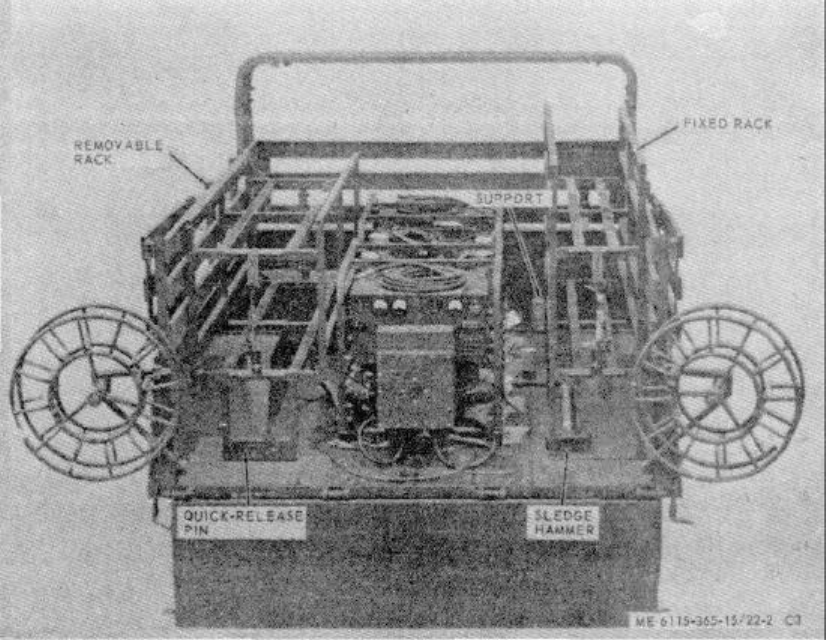
TM 5-6115-365-15
C3,
Figure 22-2. Accessories, racks, and reels.
WARNING
Wheels must be blocked, brakes set,
and leg prop down in support
position before attempting to roll up
the tarpaulin, and before start- ing to
assemble or set-up equipment for
operation.
b. Preparation Before Starting.
(1) Remove tarpaulin and roof bows.
(2) Unload equipment from racks.
(3) Unscrew thumbscrews that secure
roadside rack to trailer body and remove rack.
(4) Remove generator set covers.
(5) Remove engine oil pan plug and install
drain line with shut-off cock. Turn the shut-off cock so
that oil will not drain out. Refer to LO 2808-203-14 and
put the proper amount of engine oil in the engine.
(6) Install the engine spark plugs. Torque to
23 - 25 ft. lbs.
(7) Install the generator set ground cables to
the sets and to the ground stud under the distribution
box. (8) Assemble the 3 piece ground rod and
install it or ground the trailer as directed in c below.
(9) Attach the fuel hose to the two- way valve
and to the fuel line connector on the trailer floor
(fig. 22-3). If fuel is to be supplied from a 55-gallon
drum, attach the 25-foot hose to the drum and to the 2-
way valve. The generator set gasoline tank under the
set should be used for emergency operation only. Fill
the trailer fuel tank. A gage is provided on the top of the
tank to indicate the fuel level in the tank.
22-3
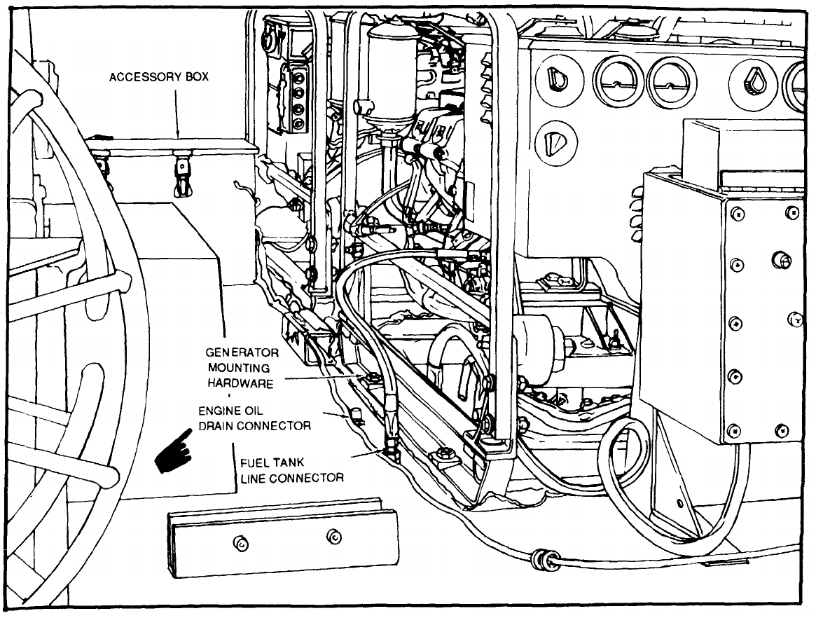
TM 5-6115-365-15
Figure 22-3. Fuel line connections
22-4 Change 11

TM 5-6115-365-15
(10) Connect the load cables from the
distribution box to the generator sets as shown in
figure 22-4. Attach the cables to the floor of the trailer
with the clamps provided. Connect the out-going load
cables to the distribution box load terminals.
c. Grounding.
WARNING
Never operate the generator set until
it has been properly grounded.
Electrical defects in the load lines or
equipment could cause death by
electrocution.
(1) The ground may be any of three methods,
depending on the location and the terrain.
(a) A ground rod driven to a depth of 8
feet. (b) An underground metallic water
piping system. (c) A metal plate (9 square ft) buried to
a depth of four feet.
(2) The ground lead must be no. 6 AWG
copper wire bolted or clamped to the rod, plate, or piping
system. (3) Connect the other end of the ground lead
to the ground stud on the distribution box support.
22-4. Starting
WARNING
Never operate the generator set in an
enclosed area unless exhaust gases
are piped outside. Inhalation of
exhaust fumes may result in serious
illness or death.
a. Perform the pre-starting operations in
TM 5-6115-271-14.
b. Position the transfer switch to the desired
generator.
c. Start the generator as described in
TM 5-6115-271-14.
22-5. Stopping
Stop the generator set as described in
TM 5-6115-271-14.
22-6. Operation
Operate the generator set as instructed in
TM 5-6115-271-14. Use fuel from the trailer-mounted
fuel tank. When refueling tank, operate the engine with
fuel from the generator set fuel tank until sediment has
had a chance to settle in the trailer fuel tank. Use the
fuel transfer valve to perform fuel transfer operations.
The load transfer switch on the distribution box is used
to transfer the electrical load from one generator to the
other (Fig. 22-5).
Section III. OPERATOR'S MAINTENANCE INSTRUCTIONS
Operator's maintenance of the power unit is concerned
with keeping the generator sets lubricated; the fuel tank
filled; and cleaning and servicing the fuel filters
and air cleaners as described in TM 5-6115-271-14.
Removal of dust and dirt from the equipment is also a
routine maintenance function of the operator.
Section IV. ORGANIZATIONAL MAINTENANCE INSTRUCTIONS
22-7. Fuel System Components
a. General. The fuel system consists of a fuel tank
located beneath the trailer; the generator set fuel tanks
located beneath the generators, on the skids; and the
hoses and fittings to provide fuel to the engines. A fuel
strainer in the filler neck is removable for cleaning. The
fuel level gage is located on the top of the tank near the
filler neck.
b. Fuel Tank Replacement.
(1) Drain the fuel tank.
(2) Loosen the hose clamps (45, Fig. 22-6) on
the hose (44) to the filler neck at the tank.
(3) Remove the nuts and washers that secure
the tank hanger to the bracket and lower the tank far
enough to disconnect fuel lines, vent hose, and ground
wires on the top of the tank. Remove the tank.
Change 9 22-5
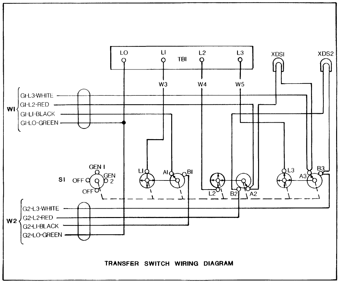
TM 5-6115-365-15
Figure 22-4. Wiring diagram.
22-6 Change 8
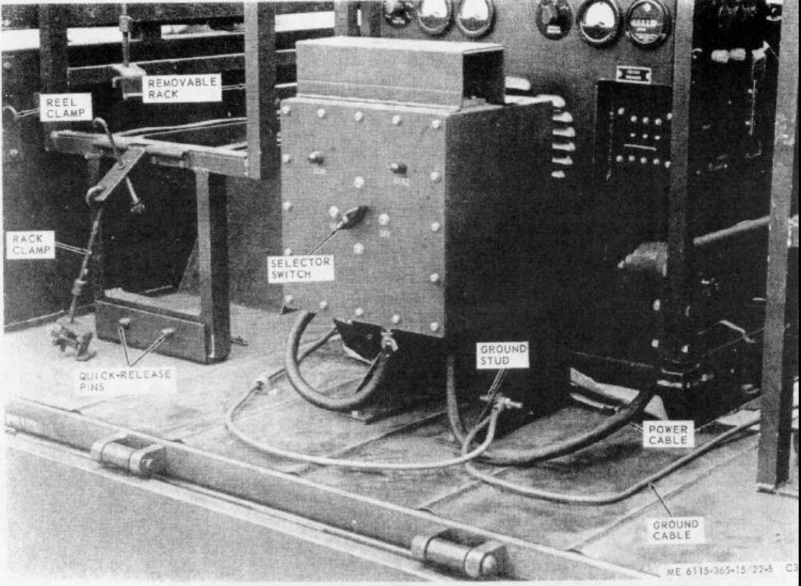
TM 5-6115-365-15
C3,
Figure 22-5. Distribution box and cables.
164-751 O - 86 - 13 22-7

TM 5-6115-365-15
c. Fuel Gage Replacement.
(1) Remove tank b above.
(2) Remove screws and washers that secure
gage (22, Fig. 22-7) to gage mount (18) and remove
gage. (3) Using serviceable gasket, install gage on
gage mount and secure with screws and washers.
(4) Reinstall tank by reversing removal
procedure b above.
d. Cleaning and Inspection.
(1) Remove tank b above, and remove fuel
gage. (2) Clean all parts with solvent and flush out
dirt and foreign particles from inside the tank.
(3) Inspect tank for dents, rust, cracks, and
other damage. Inspect straps for defects and damaged
or missing hardware. Inspect fuel gage for damage and
proper operation.
(4) Replace defective or missing parts as
necessary.
(5) Reinstall tank by reversing removal
procedure b above.
22-8. Tarpaulin and Roof Bows
a. Removal.
(1) Remove tarpaulin from unit.
(2) Pull out chain-secured pins that secure
roof bows to trailer and remove bows.
b. Cleaning and Inspection.
(1) Clean tarpaulin with water and detergent.
Clean roof bows with solvent dampened cloth. Dry
thoroughly.
(2) Inspect tarpaulin for tears, holes, missing
or broken ropes and straps, and other defects. Inspect
bows for bends, dents, and warped condition.
c. Installation. Installation is reverse of procedure
a above. Be sure tarpaulin is treated for waterproofing
and mildew resistance before reinstalling.
22-9. Trailer Leg Prop
a. Removal. Remove nuts (4, Fig. 22-6), washers
(3), and capscrews (2) that secure leg prop (1) to trailer
chassis.
b. Cleaning and Inspection. Clean leg prop with
cloth dampened in solvent and dry thoroughly. Inspect
leg prop and base for bends, ease of adjustment, and
secure attachment of base plate.
c. Installation. Installation is reverse of removal
procedure a above. If trailer is to be moved, attach leg
to holder beneath trailer and pin in place.
22-10. Holders, Supports, and Brackets
Replacement of the holders, supports, and brackets is
accomplished by removing attaching hardware and
installing serviceable components.
22-11. Reels and Reel Supports
(fig. 22-11)
a. Removal.
(1) Remove cotter pin (75), nut (74), and
washer (73) and remove reel (5).
(2) Drive out roll pin (72) and remove collar
(71) and spindle (70) from reel mount shaft.
(3) Remove capscrew (66) and washers (67
and 68) and remove shaft from reel mount.
(4) Remove cotter pins and remove reel
mount from reel support.
(5) Remove nuts, washers, and capscrews
that secure reel support to trailer body and remove
support.
b. Installation. Installation is reverse of removal.
Put a small amount of GAA on the shaft before
reinstalling the spindle (70).
Section V. DIRECT AND GENERAL SUPPORT AND DEPOT
MAINTENANCE INSTRUCTIONS
22-12. Generator Set
a. Removal.
(1) Disconnect fuel lines at fuel transfer valve.
(2) Disconnect electrical load cables from
panel.
22-8 Change 9
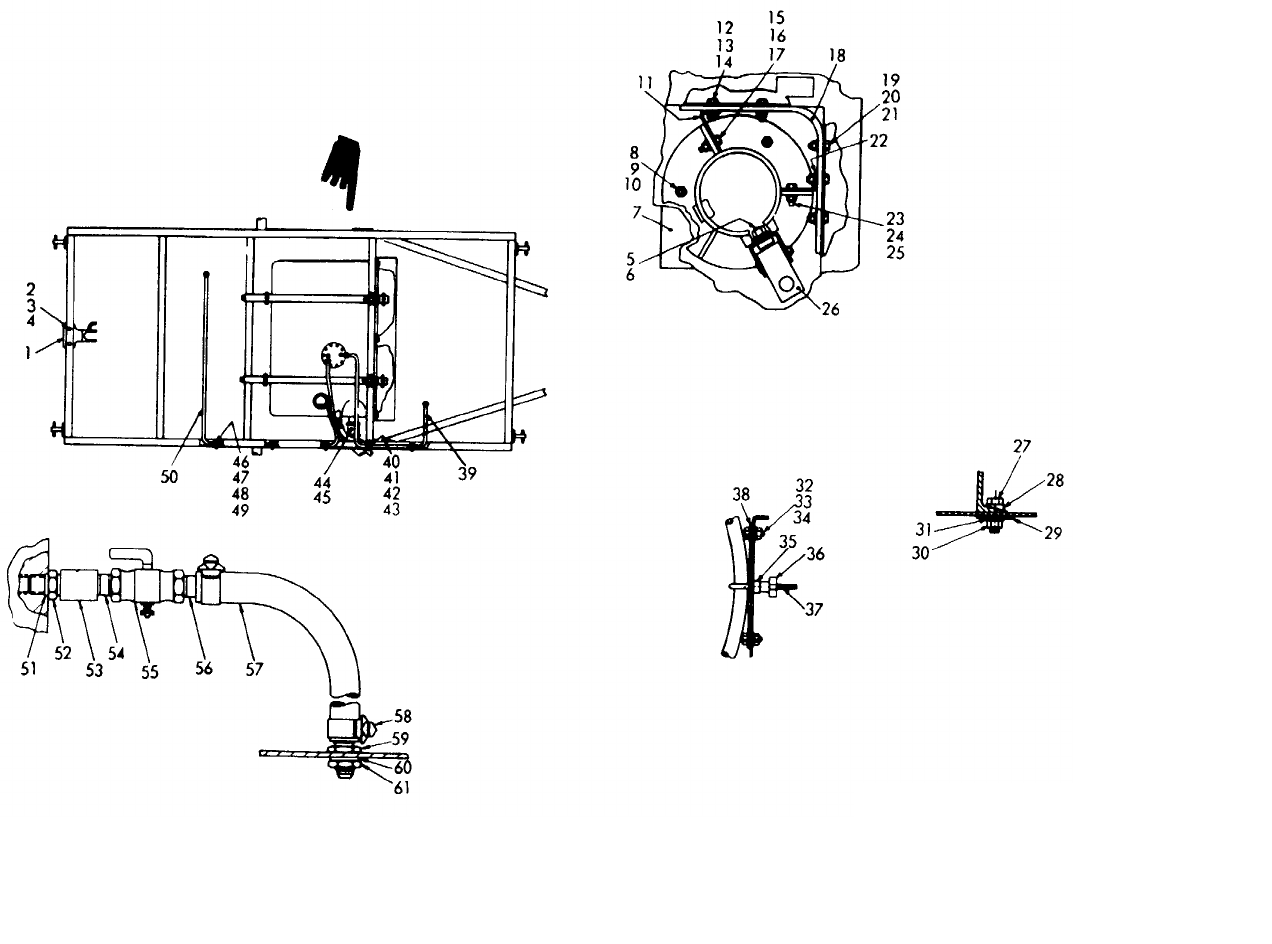
TM 5-6115-365-15
C3,
Figure 22-6. Fuel supply fittings and oil drain.
ME 6115-365-15/22-6 C3
Change 3 22-9
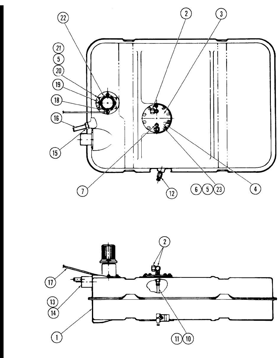
TM 5-6115-365-15
Figure 22-7. Fuel Tank Assembly.
22-10 Change 9

TM 5-6115-365-15
(3) Remove nuts (30, Fig. 22-6), washers (29
and 31), capscrews (27), and beveled washers (28) that
secure generator set to trailer.
(4) Remove generator set from trailer.
b. Installation. Installation is reverse of removal
procedure a above. Make sure that the beveled
washers (28) are properly positioned so that generator
set is securely mounted to the trailer body.
22-13. Distribution Box
a. Removal.
(1) Disconnect the load lines at the generator
sets and the ground wires at the ground stud (16,
Fig. 22-8) on the distribution box bracket (10). Loosen
cable clamps so that cables will be removed with
distribution box.
(2) Remove nuts (13), washers (12),
stiffeners (22), and capscrews (11) that secure bracket
to trailer bed and remove distribution box with cables.
b. Disassembly.
(1) Remove screws (47) and washers (48 and
49) and remove cover and gasket (45) from box.
(2) Disconnect and tag interval wiring at
switch and indicator lights.
(3) Remove knob from switch.
(4) Remove nuts (29), washers (28), and
screws (27) with "O" rings (30) and remove switch (43)
and "O" ring (46) from box.
(5) To remove bracket from box, remove nuts
(9) and washers (8) and separate bracket from box.
(6) To remove terminal board (22), remove
nuts (36), washers (34 and 35), and machine screws
(33), and separate
Change 9 22-10.1/(22-10.2 blank)
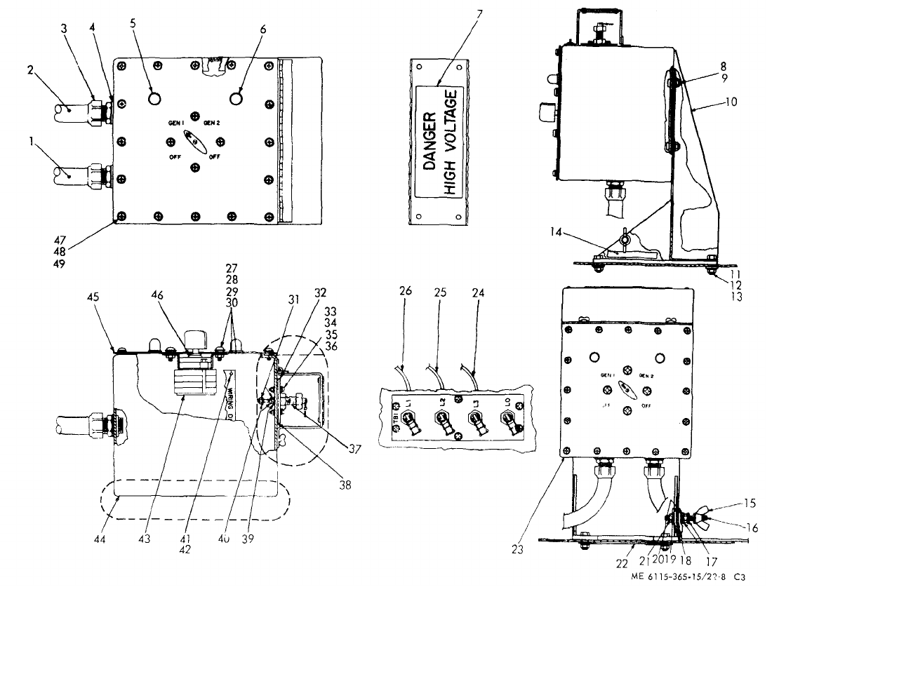
ME 6115-365-15/22-8 C3
TM 5-6115-365-15
C3,
Figure 22-8. Distribution box.
22-11
TM 5-6115-365-15
C3,
terminal board and gasket (38) from box.
(7) To remove cables, loosen stuffing tube
nuts and cable nuts and pull cables from box. Be careful
not to damage the "O" rings (4).
c. Reassembly. Reassembly is reverse of
disassembly procedures b above. Be sure that "O" rings
and gaskets are serviceable before reinstalling.
d. Installation. Installation is reverse of removal a
above. Refer to figure 22-4 to assure that electrical load
cables are properly connected.
22-14. Removable Rack Assembly
(Fig. 22-9)
a. Removal. Pull the quick-release pins, unscrew
the screw-knobs, and remove the rack from the trailer.
b. Repair. Repair of the rack assembly consists of
replacing the clamps (1), the
runners (24), the nylon runners (22), and the
straightening and welding of the braces and
longitudinals.
c. Installation. Installation is reverse of removal
procedure a above.
22-15. Curbside Rack Assembly
(fig. 22-10)
a. Removal. Remove the nuts, washers, stiffeners,
and capscrews that secure the rack to the floor of the
trailer. Remove the capscrews and washers that secure
the rack to the side of the trailer. Remove the rack.
b. Repair. Repair of the rack assembly consists of
replacing the clamps (1), the runners (22), the nylon
runners (24), and the straightening and welding of the
braces and longitudinals.
c. Installation. Installation is reverse of removal
procedure a above.
22-12
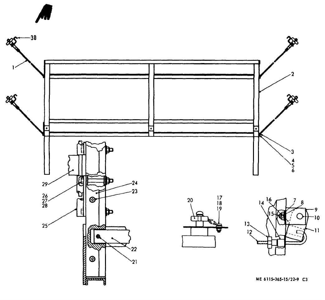
ME 6115-365-15/22-9 C3
TM 5-6115-365-15
Figure 22-9. Removable rack assembly.
Change 8 22-13
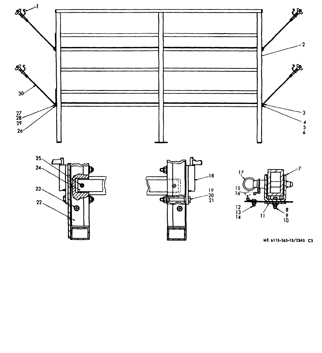
ME 6115-365-15/22-10 C3
TM 5-6115-365-15
Figure 22-10. Curbside rack assembly.
22-14
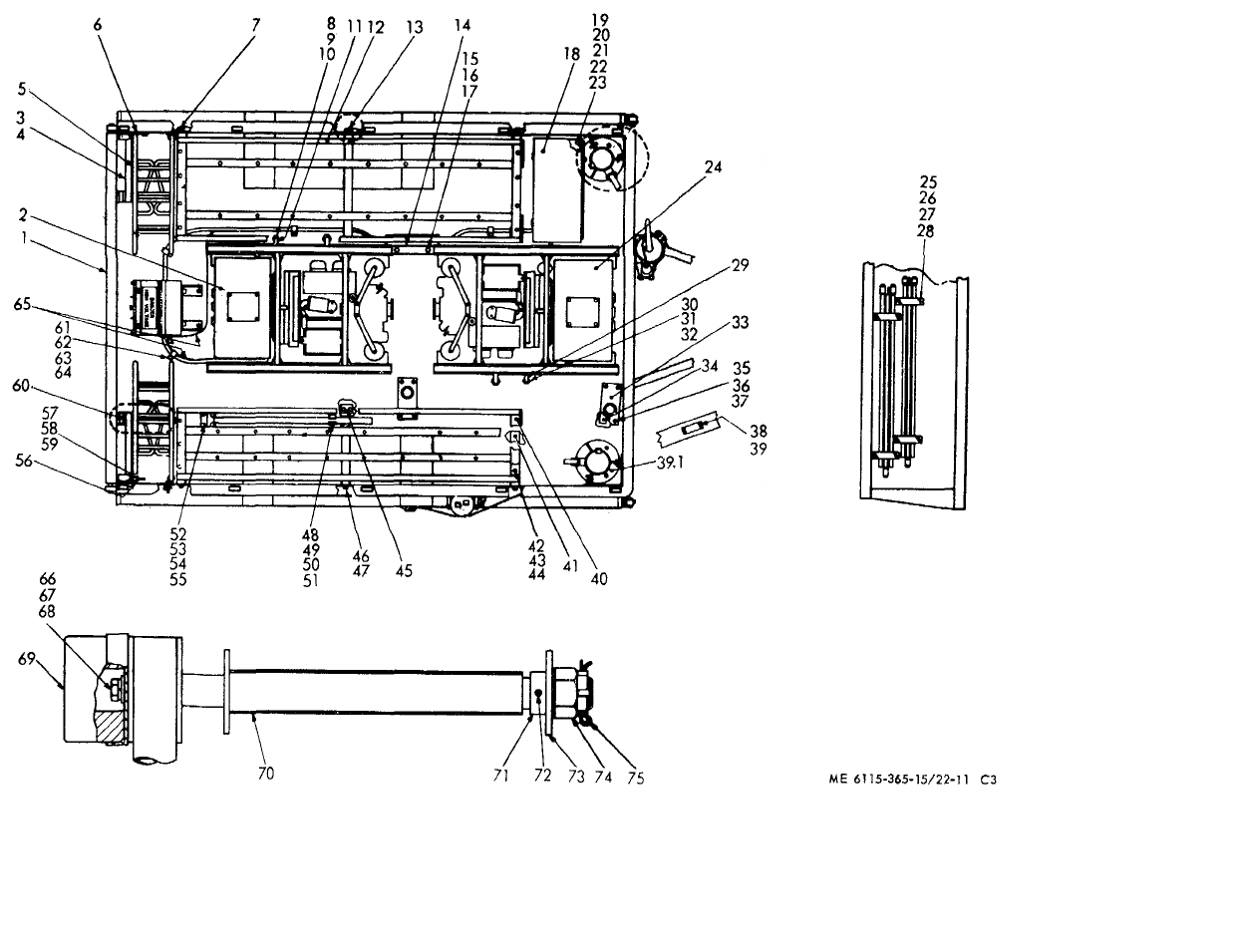
ME 6115-365-15/22-11 C3
TM 5-6115-365-15
C3,
Figure 22-11. Basic trailer with accessories.
22-15
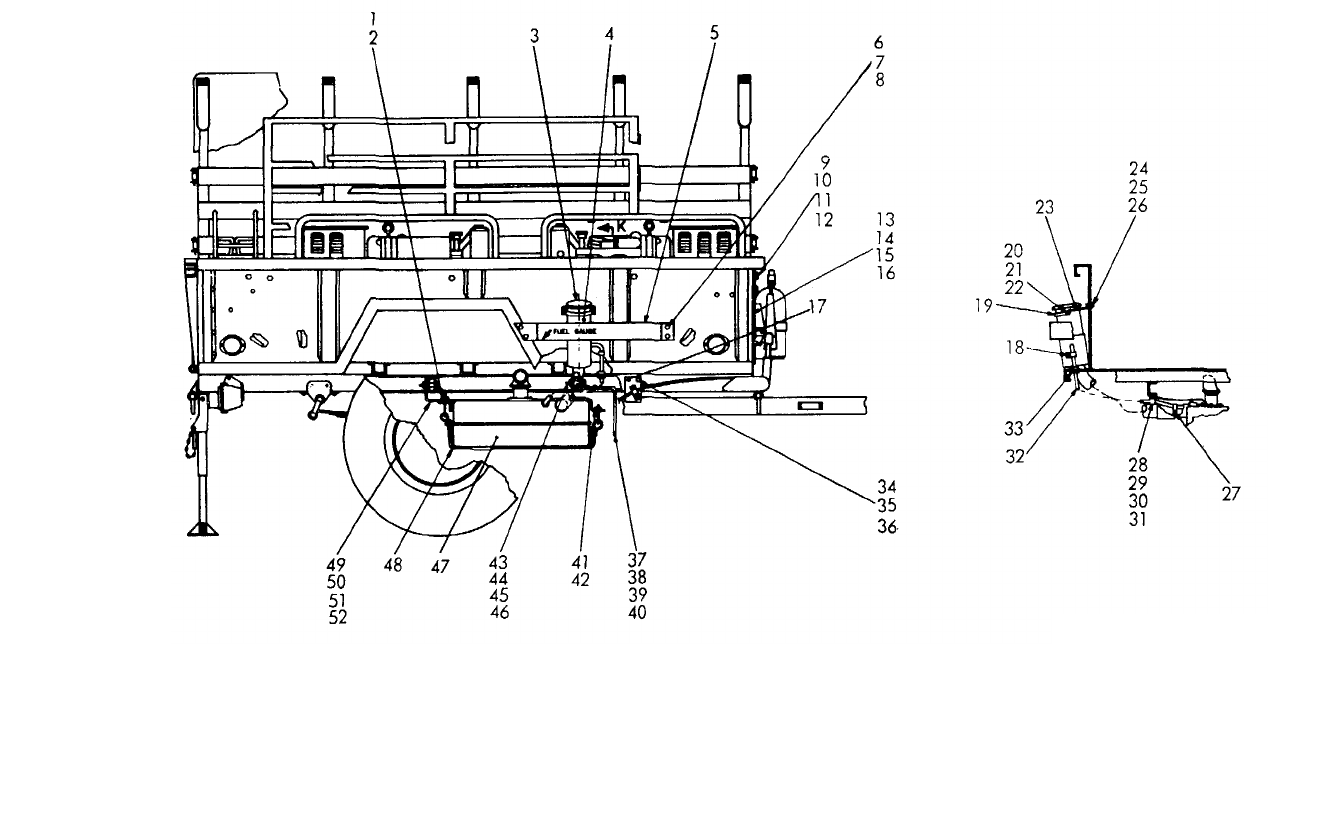
TM 5-6115-365-15
C3,
Figure 22-12. Trailer with fuel tank mounted.
ME 6115-365-15/22-12 C3
22-16

(1) (2) (3) (4) (5) (6) (7)
FEDERAL DESCRIPTION UNIT QTY 15-DAY ORGANIZATIONAL ILLUS-
SMR STOCK OF INC MAINTENANCE ALW RATION
CODE NUMBER USABLE MEAS IN (a) (b) (c) (d) (a) (b)
ON UNIT FIG ITEM
REF NUMBER & MFG CODE CODE 1-5 6-20 21-50 51-100 NO. NO.
TM 5-6115-365-15
C3,
PART I - PU-625/G
00001 REPAIR PARTS FOR ORGANIZATIONAL MAINTENANCE
00002 GROUP 03 - FUEL SYSTEM
00003 0306 - TANKS, LINES AND FITTINGS
X2 0BRACKET: FILLER NECK MTG EA 122- 23
00005 13205E5080 (97403) 12
X2 0BRACKET: TANK STRAP MTG, REAR EA 2 22- 49
00006 13205F4952 (97403) 12
0BRACKET: TANK SUPPORT EA 2****22- 48
00007 13205F4953 (97403) 12
P02910-911-0081 CAP: FUEL TANK, TAG VEHICULAR, FORDING EA 1****22- 3
00008 MS35645-2 (96906) 12
05305-068-0502 CAPSCREW, HEXAGON HEAD: 1/4-20 X 3/4 IN. LG EA 4****22- 6
00009 MS90725-6 (96906) 12
05305-225-3840 CAPSCREW, HEXAGON HEAD: 1/4-20 X 7/8 IN. LG EA 3****22- 24
00010 MS90725-7 (96906) 12
05305-225-3839 CAPSCREW, HEXAGON HEAD: 1/4-20 X 1 IN. LG EA 2****22- 20
00011 MS90725-8 (96906) 12
05305-269-3209 CAPSCREW, HEXAGON HEAD: 3/8-16 X 3/4 IN. LG EA 3****22- 38
00012 MS90725-58 (96906) 12
05305-269-3215 CAPSCREW, HEXAGON HEAD: 3/8-16 X 1 3/4 IN. LG EA 2****22- 50
00013 MS90725-65 (96906) 12
05305-269-3217 CAPSCREW, HEXAGON HEAD: 3/8-16 X 2 1/4 IN. LG EA 2****22- 44
00014 MS90725-67 (96906) 12
04730-908-3195 CLAMP: HOSE, 7/16-25/32 IN. RANGE EA 2****22- 27
00015 MS35842-10 (96906) 12
04730-909-8627 CLAMP: HOSE, 1 13/16 X 2 3/4 IN. RANGE EA 2****22-6 45
00016 MS35842-13 (96906)
05340-106-0551 CLAMP: LOOP, CUSHIONED, 5/8 IN. OD EA 2****22-6 40
00017 MS211047D10 (96906)
05340-106-0551 CLAMP: LOOP, CUSHIONED, 5/8 IN. OD EA 3****22-6 46
00018 MS21104D10 (96906)
05340-106-0552 CLAMP: LOOP, CUSHIONED, 3/4 IN. OD EA 1****22- 31
00019 MS21104D12 (96906) 12
X2 0FILLER: FUEL TANK EA 122- 4
0020 13205E5081 (97403) 12
X2 0FITTING: 37 DEG FLARE, FUEL LINE CONNECTOR EA 222- 30
00021 SAEJ514AF1G10C (81343) 11
05325-181-9846 GROMMET: 3/4 IN. DIA EA 1****22- 33
00022 MS35489-120 (96906) 12
X2 0GUARD: FUEL FILLER EA 122- 5
00023 13205E5083 (97403) 12
22-17

(1) (2) (3) (4) (5) (6) (7)
FEDERAL DESCRIPTION UNIT QTY 15-DAY ORGANIZATIONAL ILLUS-
SMR STOCK OF INC MAINTENANCE ALW RATION
CODE NUMBER USABLE MEAS IN (a) (b) (c) (d) (a) (b)
ON UNIT FIG ITEM
REF NUMBER & MFG CODE CODE 1-5 6-20 21-50 51-100 NO. NO.
TM 5-6115-365-15
C3,
02910-881-3433 HOSE: 1/2 IN. ID X 3/4 IN. OD X 24 IN. LG EA 1****22- 32
00024 MILH13444TYPE2 (81349) 12
04720-879-4091 HOSE ASSEMBLY: 5/16 IN. OD X 90 IN. LG EA 1****22-6 50
00025 MS28741-5-0900 (96906)
P04720-289-4488 HOSE ASSEMBLY:DETACHABLE FITTING, 5/16 IN. OD X 18 IN. LG EA 2****22- 29
00026 MS28741-5-0180 (96906) 11
P04721-781-4517HOSE ASSEMBLY: DETACHABLE FITTING, 5/16 IN. OD X 50 IN. LG EA 1****22-6 39
00027 MS28741-5-0500 (96906)
X2 0HOSE: FUEL, 2 IN. ID X 2 1/2 IN. OD X 3 IN. LG EA 122-6 44
00028 SAEJ30CLASS30R2TYPE2 (81343)
X2 0LOCKNUT: 37 DEG FLARE, 1/2-20 THD SIZE EA 222- 32
00029 SAEJ514AF1G10A (81343) 11
05310-877-5797 NUT, SELF-LOCKING, HEXAGON HEAD: NO. 10-32 THD SIZE EA 1****22- 30
00030 MS21044N3 (96906) 12
05310-877-8797 NUT, SELF-LOCKING, HEXAGON HEAD; 10-32 THD SIZE EA 2****22-6 43
00031 MS21044N3 (96906)
05310-877-8797 NUT, SELF-LOCKING, HEXAGON HEAD: NO. 10-32 THD SIZE EA 3****22-6 49
00032 MS21044N3 (96906)
05310-088-1251 NUT, SELF-LOCKING, HEXAGON HEAD: 1/4-20 THD SIZE EA 4****22- 8
00033 MS51922-1 (96906) 12
05310-088-1251 NUT, SELF-LOCKING: 1/4-20 THD SIZE EA 2****22- 22
00034 MS51922-1 (96906) 12
05310-088-1251 NUT, SELF-LOCKING: 1/4-20 THD SIZE EA 3****22- 26
00035 MS51922-1 (96906) 12
05310-087-4652 NUT, SELF-LOCKING: 3/8-16 THD SIZE EA 3****22- 40
00036 MS51922-17 (96906) 12
05310-087-4652 NUT, SELF-LOCKING: 3/8-16 THD SIZE EA 2****22- 42
00037 MS51922-17 (96906) 12
05310-087-4652 NUT, SELF-LOCKING, HEXAGON: 3/8-16 THD SIZE EA 2****22- 46
00038 MS57922-7 (96906) 12
05310-087-4652 NUT, HEXAGON HEAD: 3/8-16 THD SIZE EA 4****22- 52
00039 MS51922-17 (96906) 12
X2 0PIPE: SPACER, 1/2 IN. ID, STD, BLK (AS REQUIRED) FT 22- 43
00040 ASTMA120 (00000) 12
22-18
(1) (2) (3) (4) (5) (6) (7)
FEDERAL DESCRIPTION UNIT QTY 15-DAY ORGANIZATIONAL ILLUS-
SMR STOCK OF INC MAINTENANCE ALW RATION
CODE NUMBER USABLE MEAS IN (a) (b) (c) (d) (a) (b)
ON UNIT FIG ITEM
REF NUMBER & MFG CODE CODE 1-5 6-20 21-50 51-100 NO. NO.
TM 5-6115-365-15
05305-989-7435 SCREW, MACHINE, PAN HEAD: 10-32 x 5/8 IN. LG EA 1****22-12 28
00041 MS35207-264 (96906)
05305-989-7435 SCREW, MACHINE, PAN HEAD: 10-32 x 5/8 IN. LG EA 3****22-6 47
00042 MS35207-264 (96906)
05305-989-7435 SCREW, MACHINE, PAN HEAD: 10-32 x 5/8 IN. LG EA 2****22-6 41
00043 MS35207-264 (96906)
X2 0SHIELD: FUEL TANK EA 122-12 37
00044 13205E4951 (97403)
X2 0STRAP FILLER BRACKET EA 122-12 19
00045 13205E5082 (97403)
P02910-01-108-0468 TANK ASSEMBLY: FUEL, 2 FILTER EA 1****22-12 47
00046 13225E8390 (97403)
X2 04820-845-1096 COCK: DRAIN EA 122-7 12
00047 MS35783-2 (96906)
X2 04820-00-845-1096 ELBOW 90-37 DEG x 5/16 IN. OD EA 222-7 7
00049 MS20822-5 (96906)
P0CAP EA 2****22-7 2
00051 MS51532B5 (96906)
X2 06680-00-421-1551 GAGE: LIQUID LEVEL EA 122-7 22
00052 13216E7459 (97403)
X2 05330-01-165-6917 GASKET GAGE MTG EA 122-7 19
00054 13216E7460 (97403)
X2 0GASKET: LEATHER EA 122-7 13
00055 13222E5346 (97403)
X2 0GASKET: PLATE MTG EA 122-7 4
00056 13222E5351 (97403)
X2 0GROUND WIRE ASSEMBLY EA 122-7 17
00057 13216E7462 (97403)
X2 02910-01-154-7051 MOUNT: GAGE EA 122-7 18
00058 13216E7458 (97403)
X2 0NUT INVERTED, 1/2 IN. OD, 3/4-18 THD SIZE EA 122-7 15
00059 13218E0145-7 (97403)
X2 0PLATE: 2 CONNECTOR EA 122-7 3
00060 3216E7454-2 (97403)
X2 05305-00-993-1848 SCREW, MACHINE: NO. 12-24 x 3/4 IN. LG EA 10 22-7 6
00061 MS35207-265 (96906)
05305-984-6193 NUT: INVERTER FLARE EA 2****22-7 10
00062 13218E0145-4 (97403)
05305-00-993-1848 SCREW, PAN HEAD: NO. 10-32 x 5/8 IN. LG EA 16 ****22-7 20
00063 MS35207-265 (96906)
X2 02910-00-394-9584 TANK: FUEL EA 122-7 1
00064 13225E8389 (97403)
Change 9 22-19

(1) (2) (3) (4) (5) (6) (7)
FEDERAL DESCRIPTION UNIT QTY 15-DAY ORGANIZATIONAL ILLUS-
SMR STOCK OF INC MAINTENANCE ALW RATION
CODE NUMBER USABLE MEAS IN (a) (b) (c) (d) (a) (b)
ON UNIT FIG ITEM
REF NUMBER & MFG CODE CODE 1-5 6-20 21-50 51-100 NO. NO.
TM 5-6115-365-15
X2 0TUBING 1/2 IN. 00 X 035 IN WALL X 3 IN LG EA 122-7 16
00065 SAEJ526 (81343)
05310-045-3299 WASHER: LOCK, NO. 8 NOM. SIZE, EA 5****22-7 11
00066 MS35338-42 (96906)
X2 0WASHER: LOCK, NO. 12 NOM. SIZE. EA 10 22-7 5
00067 USASB27-4 (00000)
05310-045-3296 WASHER: LOCK, NO. 10 NOM SIZE, EA 6****22-7 21
00068 MS35338-43 (96906)
05310-809-8546 WASHER: FLAT, NO. 10 BSC SIZE EA 1****22-12 29
00069 MS27183-8 (96906)
05310-809-8546 WASHER: FLAT, NO. 10 BSC SIZE EA 2****22-6 42
00070 MS27183-8 (96906)
05310-809-8546 WASHER: FLAT, NO 10 BSC SIZE EA 3****22-6 48
00071 MS27183-8 (96906)
05310-809-4058 WASHER: FLAT, 1/4 IN. BSC SIZE EA 4****22-12 7
00072 MS27183-10 (96906)
05310-809-4058 WASHER: FLAT, 1/4 IN. BSC SIZE EA 2****22-12 21
00073 MS27183-10 (96906)
05310-809-4058 WASHER: FLAT, 1/4 IN. NOM. SIZE, EA 3****22-12 25
00074 MS27183-10 (96906)
05310-080-6004 WASHER: FLAT, 3/8 IN. NOM. SIZE, EA 3****22-12 39
00075 MS27183-14 (96906)
0 5310-080-6004 WASHER: 3/8 IN. BSC SIZE EA 2****22-12 41
00076 MS27183-14 (96906)
05310-080-6004 WASHER: FLAT, 3/8 IN. BSC SIZE EA 2****22-12 45
00077 MS27183-14 (96906)
05310-080-6004 WASHER: FLAT, 3/8 IN. BSC SIZE EA 4****22-12 51
00078 MS27183-14 (96906)
015310-809-5998 WASHER: FLAT, 1/2 IN. BSC SIZE EA 2****22-11 31
00079 MS27183-18 (96906)
00080 GROUP 15 – FRAME
00083 1507 – LEVELING JACKS
05305-269-3213 CAPSCREW, HEXAGON HEAD: 3/8-16 X 1 1/4 IN LG EA 3****22-6 2
00084 MS90725-62 (96906)
05310-087-4652 NUT, SELF-LOCKING 3/8-16 THD SIZE EA 3****22-6 4
00085 MS51922-17 (96906)
P0TRAILER LEG PROP ASSEMBLY EA 1****22-6 1
00086 13214E1206 (97403)
05310-080-6004 WASHER FLAT, 3/8 IN BSC SIZE EA 3****22-6 3
00087 MS27183-14 (96906)
00088 GROUP 18 – BODY
00089 1808 – STOWAGE RACKS, BOXES, CABLE REELS
PBFFF 6115-01-191-4670 ACCESSORY BOX EA 122-11 18
00090 13205E5146 (97403)
X2 0BRACKET FIRE EXTINGUISHER MTG EA 122-12 13
00092 13214E1235 (97403)
22-20 Change 8
(1) (2) (3) (4) (5) (6) (7)
FEDERAL DESCRIPTION UNIT QTY 15-DAY ORGANIZATIONAL ILLUS-
SMR STOCK OF INC MAINTENANCE ALW RATION
CODE NUMBER USABLE MEAS IN (a) (b) (c) (d) (a) (b)
ON UNIT FIG ITEM
REF NUMBER & MFG CODE CODE 1-5 6-20 21-50 51-100 NO. NO.
TM 5-6115-365-15
X2 0BRACKET: RACK TO FLOOR EA 222-10 7
00093 13216E7596 (97403)
X2 0BRACKET ASSEMBLY SWIVEL EA 422-6 26
00094 13205E5094 (97403)
X2 0BRACKET: SWIVEL EA 122-9 9
00095 13205E5107 (97403)
X2 0HOLDER EA 122-9 11
00096 13205E5109 (97403)
05315-842-3044 PIN, COTTER- 3/32 X 3/4 IN LG EA 1****
00097 MS24665-283 (96906)
X2 0PIN: SWIVEL EA 122-9 10
00098 13205E5152 (97403)
X2 0SCREW,. SHOULDER EA 122-9 15
00099 13205E5108 (97403)
05305-071-2240 CAPSCREW, HEXAGON HEAD: 1/4-20 X 3/8 IN. LG EA 2****22-11 20
00100 MS90725-11 (96906)
05305-225-3840 CAPSCREW, HEXAGON HEAD 1/4-20 X 7/8 IN. LG EA 6****22-10 8
00103 MS90725-7 (96906)
05305-225-3839 CAPSCREW, HEXAGON HEAD 1/4-20 X 1 IN. LG EA 6****22-6 8
00105 MS90725-8 (96906)
05305-071-2232 CAPSCREW, HEXAGON HEAD: 1/4-20 X 3-1/4 IN. LG EA 2****22-11 23
00107 MS90725-19 (96906)
05305-269-3209 CAPSCREW, HEXAGON HEAD: 3/8-16 X 3/4 IN. LG EA 4****22-12 14
00108 MS90725-58 (96906)
P04010-959-4775 CHAIN, WELDLESS, 6 IN. LG EA 4****22-10 15
00110 RRC271TYPE2C1-7 (81348)
X2 0HOOK EA 422-6 37
00111 13205E5134-1 (97403)
P04630-780-9350 HOOK CHAIN EA 8****22-6 16
00112 MS87006-13 (96906)
X2 0KNOB EA 422-6 36
00113 13205E5105-1 (97403)
X2 0BUMPER: REEL SHAFT EA 122-11 69
00116 13216E7598 (97403)
0 5305-068-0501 CAPSCREW, HEXAGON HEAD' 1/4-20 X 5/8 IN. LG EA 1****22-11 66
00117 MS90725-5 (96906)
X2 0COLLAR: REEL EA 122-11 71
00118 13216E7608 (97403)
X2 0NUT, CASTELLATED, HEXAGON: 3/4-16 THD SIZE EA 122-11 74
00119 MS9358-17 (96906)
05315-298-1481 PIN, COTTER: 1/8 X 1-1/2 IN. LG EA 1****22-11 75
00120 MS24665-357 (96906)
05315-143-6284 PIN, SPRING: 118 X 1 IN LG EA 1****22-11 72
00121 MS171534 (96906)
X2 0SPINDLE: REEL EA 122-11 70
00122 13216E7607(97403)
05310-809-4058 WASHER: FLAT, 1/4 IN. BSC SIZE EA 1****22-11 67
00123 MS27183-10 (96906)
05310-582-5965 WASHER: LOCK, 1/4 IN. NOM. SIZE EA 1****22-11 68
00124 MS35338-44 (96906)
PKNOB EA 422-9 13
13205E5150-1 (97403)
Change 9 22-21

(1) (2) (3) (4) (5) (6) (7)
FEDERAL DESCRIPTION UNIT QTY 15-DAY ORGANIZATIONAL ILLUS-
SMR STOCK OF INC MAINTENANCE ALW RATION
CODE NUMBER USABLE MEAS IN (a) (b) (c) (d) (a) (b)
ON UNIT FIG ITEM
REF NUMBER & MFG CODE CODE 1-5 6-20 21-50 51-100 NO. NO.
TM 5-6115-365-15
05310-809-8536 WASHER- FLAT 3/4 IN BSC SIZE EA 1****22-11 73
00125 MS27183-24 (96906)
05310-877-8797 NUT, SELF-LOCKING, HEXAGON. NO 10-32 THD SIZE EA 3****22-9 19
00127 MS21044N3 (96906)
05310-877-8797 NUT, SELF-LOCKING, HEXAGON HEAD NO 10-32 THD SIZE EA 4****22-10 14
00128 MS21044N3 (96906)
05310-088-1251 NUT, SELF-LOCKING, HEXAGON. 1/4-20 THD SIZE EA 6****22-10 10
00131 MS1922-1 (96906)
05310-088-1251 NUT, SELF-LOCKING, HEXAGON: 1/4-20 THD SIZE EA 4****22-11 22
00133 MS51922-1 (96906)
05310-088-1251 NUT, SELF-LOCKING, HEXAGON: 1/4-20 THD SIZE EA 6****22-6 10
00135 MS51922-1 (96906)
05310-087-4652 NUT, SELF-LOCKING. HEXAGON- 3/8-16 THD SIZE EA 1****22-6 6
00136 MS51922-17 (96906)
05310-087-4652 NUT, SELF-LOCKING, HEXAGON. 3/8-16 THD SIZE EA 4****22-12 16
00137 MS51922-17 (96906)
P0PIN, QUICK RELEASE EA 4****22-10 17
00138 MS17990C823 (96906)
X2 FRACK ASSY CURBSIDE EA 122-10 1
00139 13205E5129 (97403)
05305-071-2236 CAPSCREW, HEXAGON HEAD: 1/4-20 X 2 1/4 IN LG EA 16 ****22-10 19
00140 MS90725-1 (96906)
X2 05120-01-162-6222 CLAMP EA 422-10 30
00141 13205E5137-2
PAOZZ 340-01-185-6239 HINGE, LEAF BUTT EA 822-10 18
00142 13205E5125 (97403)
05310-088-1251 NUT, SELF-LOCKING. 1/4-20 THD SIZE EA 16 ****22-10 21
00143 MS1922-1 (96906)
X2 0RUNNER 11-3/4 IN LG EA 422-10 22
00144
X2 0 RUNNER- NYLON. 61 1/2 IN. LG EA 422-10 24
00145 13205E5123 (97403)
05305-984-7361 SCREW, MACHINE: 10-32 X 3/8 IN LG EA 12 ****22-10 23
00146 MS35191-270 (96906)
05310-809-4058 WASHER: FLAT, 1/4 IN. BSC SIZE EA 16 ****22-10 20
00147 MS27183-10 (96906)
05305-828-9820 SCREW: TAPPING 6-32 X 1/2 IN LG EA 40 ****22-10 25
00148 MS24627-24 (96906)
X2 0RACK ASSEMBLY: REMOVABLE EA 122-9 1
00149 13205E5128 (97403)
05305-071-2236 CAPSCREW. HEXAGON HEAD: 1/4-20 X 2 1/4 IN LG EA 16 ****22-9 26
00150 MS90725-15 (96906)
X2 0CLAMP EA 422-9 1
00151 13205E5137 (97403)
X2 0HINGE: LEAF BUTT EA 822-9 30
00152 13205E5127-1 (97403)
05310-088-1251 NUT, SELF-LOCKING: 1/4-20 THD SIZE EA 16 ****22-9 28
00153 MS51922-1 (96906)
22-22 Change 8
(1) (2) (3) (4) (5) (6) (7)
FEDERAL DESCRIPTION UNIT QTY 15-DAY ORGANIZATIONAL ILLUS-
SMR STOCK OF INC MAINTENANCE ALW RATION
CODE NUMBER USABLE MEAS IN (a) (b) (c) (d) (a) (b)
ON UNIT FIG ITEM
REF NUMBER & MFG CODE CODE 1-5 6-20 21-50 51-100 NO. NO.
TM 5-6115-365-15
05305-984-7354 SCREW, MACHINE: 10-32 X 5/16 IN. LG EA 16 ****22-9 23
00154 MS35191-269 (96906)
05305-828-9820 SCREW: TAPPING, 6-32 X 1/2 IN. LG EA 40 ****22-9 21
00155 MS24627-24 (96906)
X2 0RUNNER: 16 1/2 IN. LG EA 422-9 24
00156 13205E5121 (97403)
X2 0RUNNER: NYLON, 611/2 IN. LG EA 422-9 22
00157 13205E5123 (97403)
05310-809-4058 WASHER, FLAT, 1/4 IN. BSC SIZE EA 16 ****22-9 27
00158 MS27183-10 (96906)
P0REEL, CABLE EA 222-11 5
00159 MILR55566RC435U (81349)
05305-989-7435 SCREW, MACHINE HEAD: 10-32 X 5/8 IN,. LG EA 3****22-9 17
00160 MS35207-264 (96906)
05305-989-7434 SCREW, MACHINE, PAN HEAD: 10-32 X 3/4 IN. LG EA 4****22-10 12
00161 MS35207-263 (95906)
P05355-493-1849 SCREW, KNOB EA 3****22-9 20
00162 13205E5148(97403)
X2 0CHAIN: 6 IN LG EA 1
00163 RRC271TYPE1GRCC15STYLE1 (81349)
04030-780-9350 HOOK, CHAIN EA 1****
00164 MS87006-13 (96906)
04030-946-8497 HOOK, CHAIN EA 1****
00165 MS87006-23 (96906)
X2 0KNOB: 5/16-18 EA 1
00166 13205E5105-2 (97403)
X2 0PIN, ROLL: 1/8 X 5/8 IN LG EA 1
00167 MS171528 (96906)
05305-984-5681 SCREW: 5/16-18 X 3/4 IN. LG EA 1****
00168 MS35206-301 (96906)
X2 0SPACER EA 422-6 35
00169 13205E5119-1 (97403)
X2 0STIFFENER EA 222-10 11
00172 13205E5151 (97403)
PB000 SUPPORT, MAST EA 222-11 39
00176 13205E5099-2 (97403)
05305-225-3840 CAPSCREW, HEXAGON HEAD: 1/4-20 X 7/8 IN. LG EA 4****22-6 12
00180 MS90725-7 (96906)
05305-225-3840 CAPSCREW, HEXAGON HEAD: 1/4-20 X 7/8 IN. LG EA 2****22-6 14
00181 MS90725-7 (96906)
05305-068-0502 CAPSCREW, HEXAGON HEAD: 1/4-20 X 3/4 IN. LG EA 1****22-6 19
00182 MS90725-6 (96906)
05305-225-3840 CAPSCREW, HEXAGON HEAD: 1/4-20 X 7/8 IN. LG EA 2****22-6 23
00183 MS90725-7 (96906)
05310-088-1251 NUT, SELF-LOCKING, HEXAGON: 1/4-20 THD SIZE EA 4****22-6 14
00184 MS51922-1 (96906)
05310-088-1251 NUT, SELF-LOCKING, HEXAGON: 1/4-20 THD SIZE EA 2****22-6 16
00185 MS51922-1 (96906)
05310-088-1251 NUT, SELF-LOCKING, HEXAGON: 1/4-20 THD SIZE EA 6****22-6 21
00186 MS51922-1 (96906)
Change 9 22-23
(1) (2) (3) (4) (5) (6) (7)
FEDERAL DESCRIPTION UNIT QTY 15-DAY ORGANIZATIONAL ILLUS-
SMR STOCK OF INC MAINTENANCE ALW RATION
CODE NUMBER USABLE MEAS IN (a) (b) (c) (d) (a) (b)
ON UNIT FIG ITEM
REF NUMBER & MFG CODE CODE 1-5 6-20 21-50 51-100 NO. NO.
TM 5-6115-365-15
C3,
05310-088-1251 NUT, SELF-LOCKING, HEXAGON: 1/4-20 THD SIZE EA 2****22-6 25
00187 MS51922-1 (96906)
05310-809-4058 WASHER, FLAT: 1/4 IN. BSC SIZE EA 4****22-6 13
00188 MS527183-10 (96906)
05310-809-4058 WASHER, FLAT: 1/4 IN. BSC SIZE EA 2****22-6 15
00189 MS27183-10 (96906)
05310-809-4058 WASHER, FLAT: 1/4 IN. BSC SIZE EA 6****22-6 20
00190 MS27183-10 (96906)
05310-809-4058 WASHER, FLAT: 1/4 IN. BSC SIZE EA 2****22-6 24
00191 MS27183-10 (96906)
05310-809-8546 WASHER: FLAT, NO. 10 BSC SIZE EA 3****22-9 18
00194 MS27183-8 (96906)
05310-809-8546 WASH ER: FLAT, NO. 10 BSC SIZE EA 4****22- 13
00195 MS27183-8 (96906) 10
05310-809-4058 WASHER: FLAT, 1/4 IN. BSC SIZE EA 6****22- 9
00198 MS27183-10 (96906) 10
05310-809-4058 WASHER: FLAT, 1/4 IN. BSC SIZE EA 4****22- 21
00200 MS27183-10 (96906) 11
0531C-809-4058 WASHER: FLAT, 1/4 IN. BSC SIZE EA 6****22-6 9
00202 MS27183-10 (96906)
05310-081-6004 WASHER: FLAT, 3/8 IN. BSC SIZE EA 4****22- 15
00204 MS27183-14 (96906) 12
05310-081-6004 WASHER: FLAT, 1/2 IN. BSC SIZE EA 1****22-6 5
00205 M227183-14 (96906)
X2 0WASHER EA 422- 19
00206 13205E5114 (97403) 11
00207 GROUP 22 - BODY ACCESSORY ITEMS
00208 2202 - ACCESSORY ITEMS
X2 0BRACKET: FIRE EXTINGUISHER MTG EA 122- 9
00209 13216E7601 (97403) 12
X2 0BRACKET ASSEMBLY: SLEDGE HAMMER EA 122- 52
00210 13214E1214 (97403) 11
05305-068-0502 CAPSCREW, HEXAGON HEAD: 1/4-20 X 3/4 IN. LG EA 2****22- 53
00211 MS90725-6 (96906) 11
05305-068-0502 CAPSCREW, HEXAGON HEAD:1/4-20 X 3/4 IN. LG EA 1****22- 49
00212 MS90725-6 (96906) 11
05305-068-0502 CAPSCREW, HEXAGON HEAD: 1/4-20 X 3/4 IN. LG EA 2****22- 15
00213 MS90725-6 (96906) 11
05305-068-0502 CAPSCREW, HEXAGON HEAD: 1/4-20 X 3/4 IN. LG EA 8****22- 26
00214 MS90725-6 (96906) 11
05305-269-3209 CAPSCREW, HEXAGON HEAD: 3/8-16 X 3/4 IN. LG EA 4****22- 10
00215 MS90725-58 (9690b) 11
05306-225-8498 CAPSCREW, HEXAGON HEAD: 5/16-18 X 7/8 IN. LG EA 1****22- 34
00216 MS90725-33 (96906) 11
X2 02590-932-7298 CLAMP, GROUND ROD EA 422- 25
00217 13212E3617 (97403) 11
X2 05340-914-2578 CLIP, SPRING, SLEDGE HAMMER EA 122- 48
00218 13214E1213-1 (97403) 11
22-24

(1) (2) (3) (4) (5) (6) (7)
FEDERAL DESCRIPTION UNIT QTY 15-DAY ORGANIZATIONAL ILLUS-
SMR STOCK OF INC MAINTENANCE ALW RATION
CODE NUMBER USABLE MEAS IN (a) (b) (c) (d) (a) (b)
ON UNIT FIG ITEM
REF NUMBER & MFG CODE CODE 1-5 6-20 21-50 51-100 NO. NO.
TM 5-6115-365-15
C3,
X2 0GUARD, CABLE EA 122-11 14
00219 13216E7597 (97403)
05310-088-1251 NUT, SELF-LOCKING, HEXAGON: 1/4-20 THD SIZE EA 1****22-11 51
00220 MS51922-1 (96906)
05310-088-1251 NUT, SELF-LOCKING, HEXAGON: 1/4-20 THD SIZE EA 2****22-11 55
00221 MS51922-1 (96906)
05310-088-1251 NUT, SELF-LOCKING: 1/4-20 THD SIZE EA 8****22-11 28
00222 MS51922-1 (96906)
05310-087-4652 NUT, SELF-LOCKING, HEXAGON: 3/8-16 THD SIZE EA 4****22-12 12
00223 MS51922-17 (96906)
05310-984-3806 NUT, SELF-LOCKING, HEXAGON: 5/16-18 THD SIZE EA 1****22-12 36
00224 MS5122-9 (96906)
X2 0PLATE: BRAKE CABLE MTG EA 122-12 17
00225 13205E5133 (97403)
05310-809-4058 WASHER: FLAT, 1/4 IN. BSC SIZE EA 2****22-11 54
00226 MS27183-10 (96906)
05310-809-4058 WASHER: FLAT, 1/4 IN. BSC SIZE EA 1****22-11 50
00227 MS27183-10 (96906)
05310-809-4058 WASHER: FLAT, 1/4 IN. BSC SIZE EA 2****22-11 16
00228 MS27183-10 (96906)
05310-809-4058 WASHER: FLAT, 1/4 IN. BSC SIZE EA 8****22-11 27
00229 MS27183-10 (96906)
05310-080-6004 WASHER: FLAT, 3/8 IN. BSC SIZE EA 4****22-12 11
00230 MS27183-14 (96906)
05310-081-4219 WASHER: FLAT, 5/16 IN. BSC SIZE EA 1****22-12 35
00231 MS27183-12 (96906)
00232 2210 - DATA PLATES
X2 0PLATE, IDENTIFICATION: GROUND TERMINAL EA 122-8 14
00233 13205E4918 (97403)
X2 0PLATE, IDENTIFICATION: PU-625/G EA 122-11 38
00234 13205E4916-19 (97403)
05305-253-5614 SCREW, DRIVE: NO. 4-7 X .19 IN. LG EA 4****22-11 39
00235 MS21318-20 (96906)
00236 GROUP 29 - AUXILIARY GENERATORS AND ENGINES
00237 2901 - GENERATOR AND ENGINE ASSEMBLY
05305-782-9494 CAPSCREW, HEXAGON HEAD: 1/2-13 X 13/4 IN. LG EA 8****22-6 27
00238 MS90725-14 (96906)
05310-225-6993 NUT, SELF-LOCKING: 1/2-13 EA 8****22-6 30
00240 MS51922-33 (96906)
X2 0WASHER: 1/2 IN. EA 822-6 29
00241 13216E7602 (97403)
05310-809-5998 WASHER: 1/2 IN. NOM. SIZE EA 8****22-6 31
00242 MS27183-18 (96906)
X2 0WASHER: BEVELED EA 822-6 28
00243 1306E4482-2 (97403)
22-25
(1) (2) (3) (4) (5) (6) (7)
FEDERAL DESCRIPTION UNIT QTY 15-DAY ORGANIZATIONAL ILLUS-
SMR STOCK OF INC MAINTENANCE ALW RATION
CODE NUMBER USABLE MEAS IN (a) (b) (c) (d) (a) (b)
ON UNIT FIG ITEM
REF NUMBER & MFG CODE CODE 1-5 6-20 21-50 51-100 NO. NO.
TM 5-6115-365-15
00244 2916 - ENGINE LUBRICATION SYSTEM
04730-270-4581 ADAPTER: 1/2-20 X 1/4-18 EA 2****22-6 52
00245 5AEJ514 (81343)
P04730-908-3194 CLAMP EA 4****22-6 58
00246 MS35842-11 (96906)
04820-277-1765 COCK, PLUG, SPRING, KEY: 1/4-18 X 1/4-18 THD SIZE EA 2****22-6 55
00247 MS35930-2 (96906)
M04720-00-670-6037 HOSE: 1/2-10 X 10 IN. LG EA 2****22-6 57
00248 SAEJ30CL30RSTYPE1 (81343)
P04730-684-1032 HOSE: 1/2-10 IN. ID (AS REQUIRED) FT ****
00249 SAEJ30CL30RSTYPE1 (81343)
05310-584-5272 LOCK WASHER EA 2****22-6 60
00250 MS35332-48 (96906)
04730-196-1465 NIPPLE, CLOSE EA 2****22-6 54
00251 WWN351 (81348)
0NIPPLE: 1/4 IN. IPS EA 2****22-6 53
00252 WWP521 (81348)
04730-196-1502 NIPPLE: 1/4 IN. IPS X 1-1/2 IN. LG EA 2****22-6 56
00253 WWN351 (81348)
05310-282-7818 NUT EA 2****22-6 61
00254 AN924-5 (88044)
05330-00-684-3420 PACKING, PREFORMED: 0 RING EA 2****22-6 51
00255 MS28775-013 (96906)
X2 04730-277-6447 UNION: BULKHEAD EA 222-6 59
00256 AN832-5 (88044)
00257 GROUP 42 - ELECTRICAL EQUIPMENT
00258 4202 - ELECTRICAL CONTROLS
P06210-660-8195 LIGHT, INDICATOR EA 2****22-8 6
00271 13214E1391 (97403)
00300 4216 - MISCELLANEOUS WIRING AND FITTINGS
05310-877-5797 NUT, SELF-LOCKING, HEXAGON: NO. 10-32 THD SIZE EA 4****22-11 64
00301 MS21044N3 (96906)
X2 05340-106-0552 CLAMP: LOOP, 3/4 IN. OD, TUBE EA 422-11 61
00302 MS21104D12 (96906)
05310-918-6921 NUT, PLAIN, HEXAGON: JAM EA 2****22-8 21
00303 MS16203-39 (96906)
05310-543-4717 NUT, PLAIN, WING: 3/8-16 THD SIZE EA 1****22-8 15
00304 MS35425-28 (96906)
05305-989-7435 SCREW, MACHINE: 10-32 X 5/8 IN. LG EA 4****22-11 62
00305 MS35207-264 (96906)
X2 05307-722-9437 STUD: GROUNDING EA 122-8 16
00306 13214E1223 (97403)
05940-688-6010 TERMINAL LUG: CRIMP STYLE, 3/8 IN. BSC SIZE EA 2****22-8 19
00307 MS20659-10 (96906)
05310-809-8546 WASHER: FLAT, NO. 10 BSC SIZE EA 4****22-11 63
00308 MS27183-8 (96906)
22-26 Change 8
(1) (2) (3) (4) (5) (6) (7)
FEDERAL DESCRIPTION UNIT QTY 15-DAY ORGANIZATIONAL ILLUS-
SMR STOCK OF INC MAINTENANCE ALW RATION
CODE NUMBER USABLE MEAS IN (a) (b) (c) (d) (a) (b)
ON UNIT FIG ITEM
REF NUMBER & MFG CODE CODE 1-5 6-20 21-50 51-100 NO. NO.
TM 5-6115-365-15
X2 O5310-187-2413 WASHER: FLAT, ELECTRIC, 3/8 IN. BSC SIZE EA 122- 20
00309 AN961-616 (88044) 8
O5310-913-9776 WASHER: LOCK, 3/8 IN. NOM. SIZE EA 2••••22- 17
00310 MS35335-91 (96906) 8
O5310-913-9776 WASHER: LOCK, EXTERNAL TOOTH, 3/8 IN. NOM. SIZE EA 2••••22- 18
00311 MS35335-91 (96906) 8
O6145-395-8799 WIRE, ELECTRIC: NO. 6 AWG (AS REQUIRED) FT ••••22- 65
00312 QQW343TYPERBR (81348) 11
PB O6110-400-7592 DISTRIBUTION BOX 22- 23
00313 13205E5079-3 (97403) 8
XB OBRACKET, DISTRIBUTION BOX 22- 10
00314 13205E5117(97403) 8
Change 10 22-27

(1) (2) (3) (4) (5) (6) (7) (8) (9) (10)
DESCRIPTION 1-YR
DEPOT
QTY 30-DAY DS MAINT 30-DAY GS MAINT ALW
PER MAINT
ALW ILLUS-
TRATION
FEDERAL USABLE UNIT INC ALLOWANCE ALLOWANCE 100 PER (a) (b)
SMR
CODE STOCK
NUMBER
ON
REF NUMBER & MFR CODE CODE OF
MEAS IN
UNIT (a)
1-20 (b)
21-50 (c)
51-100 (a)
1-20 (b)
21-50 (c)
51-100
EQUIP
CNTGCY 100
EQUIP FIG.
NO. ITEM
NO.
TM 5-6115-365-15
C3
PART II - PU- 625/G
00001 REPAIR PARTS FOR DS, GS AND DEPOT
MAINTENANCE
00002 GROUP 03 - FUEL SYSTEM
00003 0306 - TANKS, LINES AND FITTINGS
X2 OBRACKET: FILLER NECK MTG EA 122- 23
00005 13205E5080 (97403) 12
X2 OBRACKET: TANK STRAP MTG, REAR EA 222- 49
00006 13205F4952 (97403) 12
OBRACKET: TANK SUPPORT EA 2******* *22- 48
00007 13205E4953 (97403) 12
PO2910-911-0081 CAP: FUEL TANK, TAC VEHICULAR, FORDING EA 1******* *22- 3
00008 MS35645-2 (96906) 12
O5305-068-0502 CAPSCREW, HEXAGON HEAD: 1/4-20 X 3/4 IN. LG EA 4******* *22- 6
00009 MS90725-6 (96906) 12
O5305-225-3840 CAPSCREW, HEXAGON HEAD: 1/4-20 X 7/8 IN. LG EA 3******* *22- 24
00010 MS90725-7 (96906) 12
O5305-225-3839 CAPSCREW, HEXAGON HEAD: 1/4-20 X 1 IN. LG EA 2******* *22- 20
00011 MS90725-8 (96906) 12
O5305-269-3209 CAPSCREW, HEXAGON HEAD: 3/8-16 X 3/4 IN. LG EA 3******* *22- 38
00012 MS90725-58 (96906) 12
O5305-269-3215 CAPSCREW, HEXAGON HEAD: 3/8-16 X 1 3/4 IN. LG EA 2******* *22- 50
00013 MS90725-65 (96906) 12
O5305-269-3217 CAPSCREW, HEXAGON HEAD: 3/8-16 X 2 1/4 IN,
00014 LG EA 2******* *22- 44
MS90725-67 (96906) 12
O4730-908-3195 CLAMP: NOSE, 7/16-25/32 IN. RANGE EA 2******* *22- 27
00015 MS35842-10 (96906) 12
O4730-909-8627 CLAMP: HOSE, 1 13/16 X 2 3/4 IN. RANGE EA 2******* *22-6 45
00016 MS35842-13 (96906)
O5340-106-0551 CLAMP: LOOP, CUSHIONED, 5/8 IN. OD EA 2******* *22-6 40
00017 221104D10 (96906)
O5340-106-0551 CLAMP: LOOP, CUSHIONED, 5/8 IN. OD EA 3******* *22-6 46
00018 M21104D10 (96906)
O5340-106-0552 CLAMP: LOOP, CUSHIONED, 3/4 IN. OD EA 1******* *22- 31
00019 MS21104D12 (96906) 12
X2 OFILLER: FUEL TANK EA 122- 4
00020 13205E5081 (97403) 12
X2 OFITTING: 37 DEG FLARE, FUEL LINE CONNECTOR EA 222- 30
00021 SAEJ514AF1G10C (81343) 11
O5325-184-9846 GROMMET: 3/4 IN. DIA EA 1******* *22- 33
00022 8M35489-120 (96906) 12
X2 OGUARD: FUEL FILLER EA 122- 5
00023 13205E5083 (97403) 12
O2910-881-3433 HOSE: 1/2 IN. ID X 3/4 IN. OD X 24 IN. LG EA 1******* *22- 32
00024 MILH13444TYPE2 (81349) 12
22-28
(1) (2) (3) (4) (5) (6) (7) (8) (9) (10)
DESCRIPTION 1-YR
DEPOT
QTY 30-DAY DS MAINT 30-DAY GS MAINT ALW
PER MAINT
ALW ILLUS-
TRATION
FEDERAL USABLE UNIT INC ALLOWANCE ALLOWANCE 100 PER (a) (b)
SMR
CODE STOCK
NUMBER
ON
REF NUMBER & MFR CODE CODE OF
MEAS IN
UNIT (a)
1-20 (b)
21-50 (c)
51-100 (a)
1-20 (b)
21-50 (c)
51-100
EQUIP
CNTGCY 100
EQUIP FIG.
NO. ITEM
NO.
TM 5-6115-365-15
O4720-879-4091 HOSE ASSEMBLY: 5116 IN OD x 90 IN. LG EA 1******* *22-6 50
00025 MS28741-5-0900 (96906)
PO4720-289-4488 HOSE ASSEMBLY: DETACHABLE FITTING, 5116 IN
00026 OD x 18 IN. LG EA 2******* *22- 29
MS28741-5-0180 (96906) 11
PO4721-781-4517 HOSE ASSEMBLY: DETACHABLE FITTING, 5/16 IN.
00027 OD x 50 IN. LG EA 1******* *22-6 39
MS28741-5-0500 (96906)
OHOSE: FUEL, 2 IN. ID x 2-1/2 IN. OD x 3 IN. LG EA 1******* *22-6 44
00028 SAEJ30CLASS30R2TYPE2 (81343)
X2 OLOCKNUT: 37 DEG FLARE, 1/2-20 THD SIZE EA 222- 32
00029 SAEJ514AF1G10A 181343) 11
O5310-877-5797 NUT, SELF-LOCKING, HEXAGON HEAD: NO. 10-32
00030 THD SIZE EA 1******* *22- 30
MS21044N3 (96906) 12
O5310-877-8797 NUT, SELF-LOCKING, HEXAGON HEAD: EA 2******* *22-6 43
00031 NO. 10-32 THD SIZE
MS21044N3 (96906)
O5310-877-8797 NUT, SELF-LOCKING, HEXAGON HEAD: NO. 10-32
00032 THD SIZE MS21044N3 (96906) EA 3******* *22-6 49
O5310-088-1251 NUT, SELF-LOCKING, HEXAGON HEAD: 1/4-20 EA 4******* *22- 8
00033 THD SIZE MS51922-1 (96906) 12
O5310-088-1251 NUT, SELF-LOCKING: 1/4-20 THD SIZE EA 2******* *22- 22
00034 MS51922-1 (96906) 12
O5310-088-1251 NUT, SELF-LOCKING: 1/4-20 THD SIZE EA 3******* *22- 28
00035 MS59122-1 (96906) 12
O5310-087-4652 NUT, SELF-LOCKING: 3/8-16 THD SIZE EA 3******* *22- 40
00036 MS51922-17 (96906) 12
O5310-087-4652 NUT, SELF-LOCKING 3/8-16 THD SIZE EA 2******* *22- 42
00037 MS51922-17 (96906) 12
O5310-0874652 NUT, SELF-LOCKING, HEXAGON: 3/8-16 THD SIZE EA 2******* *22- 46
00038 MS57922-7 (96906) 12
O5310-087-4652 NUT, HEXAGON HEAD 3/8-16 THD SIZE EA 4******* *22- 52
00039 MS51922-17 (96906) 12
X2 OPIPE: SPACER, 1/2 IN. ID, STD, BLD
00040 (AS REQUIRED) FT 22- 43
ASTMA120 (00000) 12
POWASHER EA 16 22-7 23
MS27183-42 (96906)
Change 9 22-29
(1) (2) (3) (4) (5) (6) (7) (8) (9) (10)
DESCRIPTION 1-YR
DEPOT
QTY 30-DAY DS MAINT 30-DAY GS MAINT ALW
PER MAINT
ALW ILLUS-
TRATION
FEDERAL USABLE UNIT INC ALLOWANCE ALLOWANCE 100 PER (a) (b)
SMR
CODE STOCK
NUMBER
ON
REF NUMBER & MFR CODE CODE OF
MEAS IN
UNIT (a)
1-20 (b)
21-50 (c)
51-100 (a)
1-20 (b)
21-50 (c)
51-100
EQUIP
CNTGCY 100
EQUIP FIG.
NO. ITEM
NO.
TM 5-6115-365-15
C3
O5305-989-7435 SCREW, MACHINE, PAN HEAD: 10-32 X 5/8 IN.
00041 LG EA 1******* *22- 28
MS35207-264 (96906) 12
O5305-989-7435 SCREW, MACHINE, PAN HEAD 10-32 X 5/8 IN.
00042 LG EA 3******* *22-6 47
MS35207-264 (96906)
O5305-989-7435 SCREW, MACHINE, PAN HEAD: 10-32 X 5/8 IN.
00043 LG EA 2******* *22-6 41
M335207-264 (96906)
X2 OSHIELD: FUEL TANK EA 122- 37
00044 13205E4951 (97403) 12
X2 OSTRAP: FILLER BRACKET EA 122- 19
00045 13205E5082 (97403) 12
PO2910-255-5038 TANK ASSEMBLY: FUEL, 2 FILTER EA 1******* *22- 47
00046 13216E7451-2 (97403) 12
X2 O4820-845-1096 COCK: DRAIN EA 122-7 12
00047 MS35783-2 (96906)
X2 OCOVER EA 1 22 8
00048 13216E7456 (97403)
X2 OELBOW: 90-37 DEG X 5/16 IN. OD EA 222-7 7
00049 SAEJ514 (81343)
FEXTENSION: WELDMENT EA 122-7 14
00050 13216E9457 (97403)
PO2910-575-0998 FILTER: FUEL EA 2******* *22-7 2
00051 13216E7451 (97403)
X2 OGAGE: LIQUID LEVEL EA 122-7 22
00052 1321687459 (97403)
X2 OGASKET: COVER EA 122-7 9
00053 13216E7455 (97403)
X2 OGASKET: GAGE MTG EA 122-7 19
00054 13216E7458 (97403)
X2 O2910-423-2730 GASKET: LEATHER EA 122-7 13
00055 13216E7451 (97403)
X2OGASKET: PLATE MTG EA 122-7 4
00056 13216E7453 (97403)
X2 OGROUND WIRE ASSEMBLY EA 122-7 17
00057 13216E7462 (97403)
X2 OMOUNT: GAGE EA 122-7 18
00058 1321689458 (97403)
X2 ONUT: INVERTED, 1/2 IN. OD, 3/4-18 THD
00059 SIZE EA 122-7 15
SAEJ512 (81343)
X2 OPLATE: 2 CONNECTOR EA 122-7 3
00060 321687454-2 (97403)
X2 OSCREW, MACHINE: NO. 12-24 X 3/4 IN. LG EA 10 22-7 6
00061 FFS92TYPE3STYLE9C (81348)
O5305-984-6193 SCREW, MACHINE: PAN HEAD, NO. 8-32 X 1/2
00062 IN. LG EA 5******* *22-7 10
MS35206-245 (96906)
O5305-989-7435 SCREW, PAN HEAD:10-32 I 5/8 IN. LG EA 6******* *22-7 20
00063 MS35207-264 (96906)
X2 OTANK: FUEL EA 122-7 1
00064 13216E7452 (97403)
X2 OTUBING 1/2 IN. OD X .035 IN. WALL X 3
00065 IN. LG EA 122-7 16
SAEJ526 (81343)
22-30
(1) (2) (3) (4) (5) (6) (7) (8) (9) (10)
DESCRIPTION 1-YR
DEPOT
QTY 30-DAY DS MAINT 30-DAY GS MAINT ALW
PER MAINT
ALW ILLUS-
TRATION
FEDERAL USABLE UNIT INC ALLOWANCE ALLOWANCE 100 PER (a) (b)
SMR
CODE STOCK
NUMBER
ON
REF NUMBER & MFR CODE CODE OF
MEAS IN
UNIT (a)
1-20 (b)
21-50 (c)
51-100 (a)
1-20 (b)
21-50 (c)
51-100
EQUIP
CNTGCY 100
EQUIP FIG.
NO. ITEM
NO.
TM 5-6115-365-15
OTUBE EA 1******* *22-7 11
00066 13218E5144-1 (97403)
X2 OWASHER LOCK, NO 12 NOM. SIZE EA 16 22-7 5
00067 MS35338-43 (96906)
O5310-045-3296WASHER, LOCK, NO. 10 NOM. SIZE EA 6******* *22-7 21
00068 MS35338-43 (96906)
O5310-809-8546 WASHER: FLAT, NO. 10 BSC SIZE EA 1******* *22- 29
00069 MS27183-8 (96906) 12
O5310-809-8546 WASHER: FLAT, NO 10 BSC SIZE EA 2******* *22-6 42
00070 MS2713-8 (96906)
O5310-809-8546 WASHER: FLAT, NO 10 BSC SIZE EA 3******* *22-6 48
00071 MS27183-8 (96906)
O5310-809-4058 WASHER: FLAT, 1/4 IN BSC SIZE EA 4******* *22- 7
00072 MS27183-10 (96906) 12
O5310-809-4058 WASHER: FLAT, 1/4 IN. BSC SIZE EA 2******* *22- 21
00073 MS27183-10 (96906) 12
O5310-809-4058 WASHER FLAT, 1/4 IN NOM. SIZE EA 3******* *22- 25
00074 MS27183-10 (96906) 12
O5310-080-6004 WASHER: FLAT, 3/8 IN. NOM. SIZE EA 3******* *22- 39
00075 MS27183-14 (96906) 12
O5310-080-6004 WASHER: 3/68 IN. BSC SIZE EA 2******* *22- 41
00076 MS27183-14 (96906) 12
O5310-080-6004 WASHER: FLAT, 318 IN. BSC SIZE EA 2******* *22- 45
00077 MS27183-14 (96906) 12
O5310-080-6004 WASHER: FLAT, 3/8 IN. BSC SIZE EA 4******* *22- 51
00078 MS27183-14 (96906) 12
O5310-809-5998 WASHER: FLAT, 1/2 IN. BSC SIZE EA 2******* *22- 31
00079 MS27183-18 (96906) 11
00080 GROUP 15-FRAME
00081 1501-FRAME ASSEMBLY
X2 R2330-898-6779 TRAILER: M-101-A1 EA 122- 1
00082 13205E5149 (97403) 11
00083 1507-LEVELING JACKS
O5305-269-3213 CAPSCREW, HEXAGON HEAD: 3/8-16 x 1-1/4 IN. LG EA 3******* *22-6 2
00084 MS90725-62 (96906)
O5310-087-4652 NUT, SELF-LOCKING: 3/8-16 THD SIZE EA 3******* *22-6 4
00085 MS51922-17 (96906)
PO2590-318-6691 TRAILER LEG PROP ASSEMBLY EA 1******* *22-6 1
00086 13214E1206 (97403)
O5310-080-6004 WASHER: FLAT, 3/8 IN. BSC SIZE EA 3******* *22-6 3
00087 MS27183-14 (96906)
Change 9 22-31
(1) (2) (3) (4) (5) (6) (7) (8) (9) (10)
DESCRIPTION 1-YR
DEPOT
QTY 30-DAY DS MAINT 30-DAY GS MAINT ALW
PER MAINT
ALW ILLUS-
TRATION
FEDERAL USABLE UNIT INC ALLOWANCE ALLOWANCE 100 PER (a) (b)
SMR
CODE STOCK
NUMBER
ON
REF NUMBER & MFR CODE CODE OF
MEAS IN
UNIT (a)
1-20 (b)
21-50 (c)
51-100 (a)
1-20 (b)
21-50 (c)
51-100
EQUIP
CNTGCY 100
EQUIP FIG.
NO. ITEM
NO.
TM 5-6115-365-15
C3
00088 GROUP 18 - BODY
00089 1808 - STOWAGE RACKS, BOXES, CABLE REELS
X2 OACCESSORY BOX EA 122- 18
00090 13205E5146 (97403) 11
X2 FBASE PLATE: MAST SUPPORT EA 222-6 7
000911 3205E5122 (97403)
X2 OBRACKET: FIRE EXTINGUISHER MTG EA 122- 13
00092 13214E1235 (97403) 12
X2 OBRACKET RACK TO FLOOR EA 222- 7
00093 1321617596 (97403) 10
X2 OBRACKET ASSEMBLY: SWIVEL EA 422-6 26
00094 13205E5094 (97403)
X2 OBRACKET :SWIVEL EA 122-9 9
00095 13205E5107 (97403)
X2 OHOLDER EA 122-9 11
00096 1320515109 (97403)
O5315-842-3044 PIN, COTTER: 3/32 1 3/4 IN. LG EA 1******* *
00097 MS24665-283 (96906)
X2 OPIN: SWIVEL EA 122-9 10
00098 13205E5152 (97403)
X2 OSCREW, SHOULDER EA 122-9 15
00099 13205E5108 (97403)
O5305-071-2240 CAPSCREW, HEXAGON HEAD: 1/4-20 X 3/8 IN. LG EA 2******* *22- 20
00100 MS90725-11 (96906) 11
F5305-068-0501 CAPSCREW, HEXAGON HEAD: 1/4-20 X 5/8 IN. LG EA 4******* *22-6 32
00101 MS90725-5 (96906)
F5305-068-0501 CAPSCREW, HEXAGON HEAD: 1/4-20 X 5/8 IN. LG EA 14 ******* *22- 57
00102 M901725-5 (96906) 11
O5305-225-3840 CAPSCREW, HEXAGON HEAD: 1/4-20 X 7/8 IN. LG EA 6******* *22- 8
00103 MS90725-7 (96906) 10
F5305-225-3840 CAPSCREW, HEXAGON HEAD: 1/4-20 X 7/8 IN. LG EA 6******* *22- 42
00104 MS90725-7 (96906) 11
O5305-225-3839 CAPSCREW, HEXAGON HEAD: 1/4-20 X 1 IN. LG EA 6******* *22-6 32
00105 MS90725-8 (96906)
F5305-071-2240 CAPSCREW, HEXAGON HEAD: 1/4-20 X 1 3/8 IN.
00106 LG EA ******** *22- 35
MS90725-11 (96906) 11
O5305-071-2232 CAPSCREW, HEXAGON HEADS: 1/4-20 X 3 /4 IN.
00107 LG EA 2******* *22-23
MS90725-19 (96906) 11
O5305-269-3209 CAPSCREW, HEXAGON HEAD: 3/8-16 X 3/4 IN. LG EA 4******* *22- 14
00108 MS90725-58 (96906) 12
F5306-225-8497 CAPSCREW, HEXAGON HEAD: 5/16-18 X 3/4 IN. LG EA 3** * * * * * * 22- 47
00109 M90725-32 (96906) 11
O4010-959-4775 CHAIN, WELDLESS, 6 IN. LG EA 4******* *22- 15
00110 RRC271TYPE2C1-7 (81348) 10
X2 OHOOK EA 422-6 37
00111 13205E5134-1 (97403)
22-32
(1) (2) (3) (4) (5) (6) (7) (8) (9) (10)
DESCRIPTION 1-YR
DEPOT
QTY
30-DAY DS MAINT
30-DAY GS MAINT
ALW
PER MAINT
ALW ILLUS-
TRATION
FEDERAL USABLE UNIT INC ALLOWANCE ALLOWANCE 100 PER (a) (b)
SMR
CODE STOCK
NUMBER
ON
REF NUMBER & MFR CODE CODE OF
MEAS
IN
UNIT (a)
1-20 (b)
21-50 (c)
51-100 (a)
1-20 (b)
21-50 (c)
51-100
EQUIP
CNTGCY
100
EQUIP FIG.
NO. ITEM
NO.
TM 5-6115-365-15
C3
PO4630-780-9350 HOOK, CHAIN EA 8******* *22- 16
00112 MS87006-13 (96906) 10
X2 OKNOB EA 422-6 36
00113 13205E5105-1 (97403)
X2 FMOUNT: REEL EA 122- 3
00114 13205E5112 (97403) 11
X2 FMOUNT: REEL EA 122- 60
00115 13250E5145 (97403) 11
X2 OBUMPER: REEL SHAFT EA 122- 69
00116 13216Z7598 (97403) 11
O5305-068-0501 CAPSCREW, HEXAGON HEAD: 1/4-20 X 5'8 IN. LG EA 1******* *22- 66
00117 MS90725-5 (96906) 11
X2 OCOLLAR: REEL EA 122- 71
00118 1321617608 (97403) 11
X2 ONUT, CASTELLATED, HEXAGON: 3/4-16 THD SIZE EA 122- 74
00119 MS9358-17 (96906) 11
O5315-298-1481 PIN, COTTER: 1/8 X 1 1/2 IN. LG EA 1******* *22- 75
00120 SM24665-357 (96906) 11
O5315-143-6284 PIN, SPRING: 1/8 X 1 IN. LG EA 1******* *22- 72
00121 MS171534 (96906) 11
X2 OSPINDLE: REEL EA 122- 70
00122 13216E7607 (97403) 11
O5310-809-4058 WASHER: FLAT, 1/4 IN. BSC SIZE EA 1******* *22- 67
00123 MS27183-10 (96906) 11
O5310-582-5965 WASHER: LOCK, 1/4 IN. NON. SIZE
00124 MS35338-44 (96906) EA 1******* *22- 68
11
O5310-809-8536 WASHER: FLAT, 3/4 IN. BSC SIZE EA 1******* *22- 73
00125 MS27183-24 (96906) 11
F5315-816-1794 PIN, COTTER: 3/32 1 IN. LG EA 4******* *22- 4
00126 MS24665-285 (96906) 11
O5310-877-8797 NUT, SELF-LOCKING, HEXAGON: NO. 10-32
00127 THD SIZE EA 3******* *22-9 19
MS21044N3 (96906)
O5310-877-8797 NUT, SELF-LOCKING, HEXAGON HEAD NO.
00128 10-32 THD SIZE EA 4* ****** *22- 14
MS21044N3 (96906) 10
F5310-088-1251 NUT, SELF-LOCKING, HEXAGON: 1/4-20 THD SIZE EA 8******* *22- 37
00129 MS51922-1 (96906) 11
F5310-088-1251 NUT, SELF-LOCKING: 1/4-20 THD SIZE EA 4****** *22-6 34
00130 MS51922-1 (96906)
O5310-088-1251 NUT, SELF-LOCKING, HEXAGON: 1/4-20 THD SIZE EA 6******* *22- 10
00131 MS51922-1 (96906) 10
F5310-088-1251 NUT, SELF-LOCKING, HEXAGON: 1/4-20 THD SIZE EA 14 ******* *22- 59
00132 MS51922-1 (96906) 11
O5310-088-1251 NUT, SELF-LOCKING, HEXAGON: 1/4-20 THD SIZE E4******* *22- 22
00133 MS51922-1 (96906) 11
F5310-088-1251 NUT, SELF-LOCKING, HEXAGON: 1/4-20 THD SIZE LA 6******* *22- 44
00134 MS51922-1 (96906) 11
O5310-088-1251 NUT, SELF-LOCKING, HEXAGON: 1/4-20 THD SIZE EA 6******* 22-6 10
00135 MS51922-1 (96906)
22-33
(1) (2) (3) (4) (5) (6) (7) (8) (9) (10)
DESCRIPTION 1-YR
DEPOT
QTY 30-DAY DS MAINT 30-DAY GS MAINT ALW
PER MAINT
ALW ILLUS-
TRATION
FEDERAL USABLE UNIT INC ALLOWANCE ALLOWANCE 100 PER (a) (b)
SMR
CODE STOCK
NUMBER
ON
REF NUMBER & MFR CODE CODE OF
MEAS IN
UNIT (a)
1-20 (b)
21-50
(c)
51-100
(a)
1-20 (b)
21-50
(c)
51-100
EQUIP
CNTGCY 100
EQUIP FIG.
NO. ITEM
NO.
TM 5-6115-365-15
O5310-087-4652 NUT, SELF-LOCKING, HEXAGON: 3/8-16 THD SIZE EA 1••••••• •22- 6
00136 MS51922-17 (96906) 6
O5310-087-4652 NUT, SELF-LOCKING, HEXAGON: 3/8-16 THD SIZE EA 4••••••• •22- 16
00137 MS51922-17 (96906) 12
POPIN, QUICK RELEASE EA 4••••••• •22- 17
00138 MS17990C823 (96906) 10
XB FRACK ASSEMBLY: CURBSIDE EA 122- 40
00139 13205E5129(97403) 11
O5305-071-2236 CAPSCREW, HEXAGON HEAD: 1/4-20X21/41N. LG EA 16 ••••••• •22- 19
00140 MS90725-1 (96906) 10
X2 OCLAMP EA 422- 30
00141 13205E5137(97403) 10
X2 OHINGE, LEAF BUTT EA 822- 18
00142 13205E5125(97403) 10
O5310-088-1251 NUT, SELF-LOCKING: 1/4-20 THD SIZE EA 16 ••••••• •22- 21
00143 MS51922-1(96906) 10
X2 ORUNNER: 113/4 IN. LG EA 422- 22
00144 10
X2 ORUNNER: NYLON, 61 1/2 IN. LG EA 422- 24
00145 13205E5123(97403) 10
O5305-984-7361 SCREW, MACHINE: 10-32 X 3/81 IN. LG EA 12 ••••••• •22- 23
00146 MS35191-270(96906) 10
O5310-809-4058 WASHER: FLAT, 1/4 IN. BSC SIZE EA 16 ••••••• •22- 20
00147 MS27183-10 (96906) 10
O5305-828-9820 SCREW, TAPPING: 6-32X 1/2 IN. LG EA 40 ••••••• •22- 25
00148 MS24627-24 (96906) 10
X2 ORACK ASSEMBLY: REMOVABLE EA 122- 12
00149 13205E5128(97403) 11
O5305-071-2236 CAPSCREW, HEXAGON HEAD: 1/4-20 X 2 1/4 EA 16 ••••••• •22- 26
00150 IN. LG 9
MS90725-15 (96906)
X2 OCLAMP EA 422- 1
00151 13205E5137(97403) 9
X2 OHINGE: LEAF BUTT EA 822- 25
00152 13205E5125(97403) 9
O5310-088-1251 NUT, SELF-LOCKING: 1/4-20 THD SIZE EA 16 ••••••• •22- 28
00153 MS51922-1 (96906) 9
O5305-984-7354 SCREW, MACHINE: 10-32 X 5/161 IN. LG EA 16 ••••••• •22- 23
00154 MS35191-269 (96906) 9
O5305-828-9820SCREW: TAPPING, 6-32X 1/2 IN. LG EA 40 ••••••• •22- 21
00155 MS24627-24 (96906) 9
X2 ORUNNER: 161/21N. LG EA 422- 24
00156 13205E5121 (97403) 9
X2 ORUNNER: NYLON, 61 1/21N. LG EA 422- 22
00157 13205E5123(97403) 9
O5310-809-4058 WASHER: FLAT, 1/4 IN. BSC SIZE EA 16 •••• •• •22- 27
00158 MS27183-10(96906) 9
PB OREEL, CABLE EA 222- 5
00159 MILR55566RC435U (81349) 11
22-34 Change 10

(1) (2) (3) (4) (5) (6) (7) (8) (9) (10)
DESCRIPTION 1-YR
DEPOT
QTY 30-DAY DS MAINT 30-DAY GS MAINT ALW
PER MAINT
ALW ILLUS-
TRATION
FEDERAL USABLE UNIT INC ALLOWANCE ALLOWANCE 100 PER (a) (b)
SMR
CODE STOCK
NUMBER
ON
REF NUMBER & MFR CODE CODE OF
MEAS IN
UNIT (a)
1-20 (b)
21-50 (c)
51-100 (a)
1-20 (b)
21-50 (c)
51-100
EQUIP
CNTGCY 100
EQUIP FIG.
NO. ITEM
NO.
TM 5-6115-365-15
C3
O5305-989-7435 SCREW, MACHINE HEAD: 10-32 X 5/8 IN. LG EA 3******* *22-9 17
00160 MS35207-264 (96906)
O5305-989-7434 SCREW, MACHINE, PAN HEAD: 10-32 X 3/4 IN. LG EA 4******* *22- 12
00161 MS35207-263 (96906) 10
PO5355-493-1849 SCREW, KNOB EA 3******* *22-9 20
00162 13205E5148 (97403)
X2 OCHAIN: 6 IN. LG EA 1
00163 RRC271TYPE1GRCC15STYLE1 (81349)
O4030-780-9350 HOOK, CHAIN EA 1******* *
00164 MS87006-13 (96906)
O4030-946-8497 HOOK, CHAIN EA 1******* *
00165 MS87006-23 (96906)
X2 OKNOB: 5/16-18 EA 1
00166 13205E5105-2 (97403)
X2 OPIN, U: 1/8 X 5/8 IN. LG EA 1
00167 MS171528 (96906)
O5305-984-5681 SCREW: 5/16-18 X 3/4 IN. EA 1******* *
00168 MS35206-301 (96906)
X2 OSPACER EA 422-6 35
00169 13205E5119-1 (97403)
X2 FSPACER PLATE EA 222-6 38
00170 13205E5144 (97403)
X2 FSTIFFENER EA 222- 34
00171 13205E5140-4 (97403) 11
X2 OSTIFFENER EA 222- 11
00172 13205E5151 (97403) 10
X2 FSTIFFENER EA 222- 41
00173 13205E5140-1 (97403) 11
X2 FSTIFFENER EA 122- 45
00174 13205E5140-3 (97403) 11
X2 FSUPPORT EA 222- 33
00175 13205E5143 (97403) 11
X2 OSUPPORT, MAST EA 222- 39-1
00176 13205E5099-2 (97403) 11
X2 FBRACKET: ANGLE EA 222-6 11
00177 13205E5124 (97403)
X2 FBRACKET: ANGLE EA 222-6 18
00178 13205E5118 (97403)
X2 FBRACKET: ANGLE EA 222-6 22
00179 13205E5132 (97403)
O5305-225-3840 CAPSCREW, HEXAGON HEAD: 1/4-20 X 7/8 IN.
00180 LG EA 4******* *22-6 12
MS90725-7 (96906)
O5305-225-3840 CAPSCREW, HEXAGON HEAD: 1/4-20 X 7/8 IN.
00181 LG EA 2******* *22-6 14
MS90725-7 (96906)
O5305-068-0502 CAPSCREW, HEXAGON HEAD: 1/4-20 X 3/4 IN.
00182 LG EA 1******* *22-6 19
MS90725-6 (96906)
O5305-225-3840 CAPSCREW, HEXAGON HEAD: 1/4-20 X 7/8 IN. LG EA 2******* *22-6 23
00183 MS90725-7 (96906)
O5310-088-1251 NUT, SELF-LOCKING, HEXAGON: 1/4-20 THD SIZE EA 4******* *22-6 14
00184 MS51922-1 (96906)
22-35
(1) (2) (3) (4) (5) (6) (7) (8) (9) (10)
DESCRIPTION 1-YR
DEPOT
QTY 30-DAY DS MAINT 30-DAY GS MAINT ALW
PER MAINT
ALW ILLUS-
TRATION
FEDERAL USABLE UNIT INC ALLOWANCE ALLOWANCE 100 PER (a) (b)
SMR
CODE STOCK
NUMBER
ON
REF NUMBER & MFR CODE CODE OF
MEAS IN
UNIT (a)
1-20 (b)
21-50
(c)
51-100
(a)
1-20 (b)
21-50
(c)
51-100
EQUIP
CNTGCY 100
EQUIP FIG.
NO. ITEM
NO.
TM 5-6115-365-15
O5310-088-1251 NUT, SELF-LOCKING, HEXAGON: 1/4-20 THD SIZE EA 2******* *22-6 16
00185 MS51922-1 (96906)
O5310-088-1251 NUT, SELF-LOCKING, HEXAGON: 1/4-20 THD SIZE EA 6******* *22-6 21
00186 MS51922-1 (96906)
O5310-088-1251 NUT, SELF-LOCKING, HEXAGON: 1/4-20 THD SIZE EA 2******* *22-6 25
00187 MS51922-1 (96906)
O5310-809-4058 WASHER, FLAT: 1/4 IN. BSC SIZE EA 4******* * 22 13
00188 MS527183-10 (96906)
O5310-809-4058 WASHER, FLAT: 1/4 IN. BSC SIZE EA 2******* *22-6 15
00189 MS27183-10 (96906)
O5310-809-4058 WASHER, FLAT: 1/41 IN. BSC SIZE EA 6******* *22-6 20
00190 MS27183-10 (96906)
O5310-809-4058 WASHER, FLAT: 1/4 IN. BSC SIZE EA 2******* *22-6 24
00191 MS27183-10 (96906)
PFSUPPORT: REEL MOUNT EA 122- 6
00192 13205E5110 (97403) 11
X2 FSUPPORT: REEL MOUNT EA 122- 56
00193 13205E5111 (97403) 11
O5310-809-8546 WASHER: FLAT, NO. 10 BSC SIZE EA 3******* *22-9 18
00194 MS27183-8 (96906)
O5310-809-8546 WASHER: FLAT, NO. 10 BSC SIZE EA 4******* *22- 13
00195 MS27183-8 (96906) 10
F5310-809-4056 WASHER: FLAT, 1 41N. BSC SIZE EA 8******* *22- 36
00196 MS27163-10 (96906) 11
F5310-809-4058 WASHER: FLAT, 1/4 IN. BSC SIZE EA 4******* *22-6 33
00197 MS27183-10 (96906)
O5310-809-4058 WASHER: FLAT, 1/4 IN. BSC SIZE EA 6******* *22- 9
00198 MS27183-10 (96906) 10
F5310-809-4058 WASHER: FLAT, 1/4 IN. BSC SIZE EA 14 ******* *22- 58
00199 MS27183-10 (96906) 11
O5310-809-4056 WASHER: FLAT, 1/4 IN BSC SIZE EA 4******* *22- 21
00200 MS27183-10 (96906) 11
F5310-809-4058 WASHER: FLAT, 1/4 IN. BSC SIZE EA 6******* *22- 43
00201 MS27183-10 (96906) 11
O5310-809-4058 WASHER: FLAT, 114 IN. BSC SIZE EA 6******* *22-6 9
00202 MS27183-10 (96906)
F5310-407-9566 WASHER: FLAT, 5116 IN. BSC SIZE EA 3******* *22- 4
00203 MS35338-45 (96906) 11
O5310-081-4004 WASHER: FLAT, 318 IN BSC SIZE EA 4******* *22- 15
00204 MS27183-14 (96906) 12
O5310-081-6004 WASHER: FLAT, 1/2 IN BSC SIZE EA 1******* *22-6 5
00205 MS27183-14 (96906)
X2 OWASHER EA 422- 19
00206 13205E5114 (97403) 11
00207 GROUP 22-BODY ACCESSORY ITEMS
00208 2202-ACCESSORY ITEMS
X2 OBRACKET: FIRE EXTINGUISHER MTG EA 122- 9
00209 13216E7601 (97403) 12
X2 OBRACKET ASSEMBLY: SLEDGE HAMMER EA 122- 52
00210 13214E1214 (97403) 11
* U. S. C. G. P. O: 1989 - 654-030/00208
22-36 Change 9

(1) (2) (3) (4) (5) (6) (7) (8) (9) (10)
DESCRIPTION 1-YR
DEPOT
QTY 30-DAY DS MAINT 30-DAY GS MAINT ALW
PER MAINT
ALW ILLUS-
TRATION
FEDERAL USABLE UNIT INC ALLOWANCE ALLOWANCE 100 PER (a) (b)
SMR
CODE STOCK
NUMBER
ON
REF NUMBER & MFR CODE CODE OF
MEAS IN
UNIT (a)
1-20 (b)
21-50 (c)
51-100 (a)
1-20 (b)
21-50 (c)
51-100
EQUIP
CNTGCY 100
EQUIP FIG.
NO. ITEM
NO.
TM 5-6115-365-15
C3
O5305-068-0502 CAPSCREW, HEXAGON HEAD: 1/4-20 X 3/4 IN. LG EA 2******* *22- 53
00211 MS90725-6 (96906) 11
O5305-068-0502 CAPSCREW, HEXAGON HEAD: 1/4-20 X 3/4 IN. LG EA 1******* *22- 49
00212 MS90725-6 (96906) 11
O5305-068-0502 CAPSCREW, HEXAGON HEAD: 1/4-20 X 3/4 IN. LG EA 2******* *22- 15
00213 MS90725-6 (96906) 11
O5305-068-0502 CAPSCREW, HEXAGON HEAD: 1/4-20 X 3/4 IN. LG EA 8******* *22- 26
00214 MS90725-6 (96906) 11
O5305-269-3209 CAPSCREW, HEXAGON HEAD: 3/8-16 X 3/4 IN. LG EA 4******* *22- 10
12
00215 MS90725-58 (96906)
O5306-225-8498 CAPSCREW, HEXAGON HEAD: 5/16-18 X 7/8 IN. LG EA 1******* *22- 34
00216 MS90725-33 (96906) 12
X2 O2590-932-7298 CLAMP, GROUND ROD EA 422- 25
002107 13212E3617 (97403) 11
X2 55340-914-2578 CLIP, SPRING, SLEDGE HAMMER EA 122- 48
00218 13214E1213-1 (97403) 11
X2 OGUARD, CABLE EA 122- 14
00219 13216E7597 (97403) 11
O5310-088-1251 NUT, SELF-LOCKING, HEXAGON:
00220 1/4-20 THD SIZE EA 1******* *22- 51
MS51922-1 (96906) 11
O5310-088-1251 NUT, SELF-LOCKING, HEXAGON: 1/4-20 THD SIZE EA 2******* *22- 55
00221 MS51922-1 (96906) 11
O5310-088-1251 NUT, SELF-LOCKING: 1/4-20 THD SIZE EA 8******* *22- 28
00222 MS51922-1 (96906) 11
O5310-087-4652 NUT, SELF-LOCKING, HEXAGON: 3/8-16 THD SIZE EA 4******* *22- 12
00223 MS51922-17 (96906) 12
O5310-984-3806 NUT, SELF-LOCKING, HEXAGON: 5/16-18 THD
00224 SIZE EA 1******* *22- 36
MS5122-9 (96906) 12
X2 OPLATE: BRAKE CABLE MTG EA 122- 17
00225 13205E5133 (97403) 12
O5310-809-4058 WASHER: FLAT, 1/4 IN. BSC SIZE EA 2******* *22- 54
00226 MS27183-10 (96906) 11
O5310-809-4058 WASHER: FLAT, 1/4 IN. BSC SIZE EA 1******* *22- 50
00227 MS27183-10 (96906) 11
O5310-809-4058 WASHER: FLAT, 1/4 IN. BSC SIZE EA 2******* *22- 16
00228 MS27183-10 (96906) 11
O5310-809-4058 WASHER: FLAT, 1/4 IN. BSC SIZE EA 8******* *22- 27
00229 MS27183-10 (96906) 11
O5310-080-6004 WASHER: FLAT, 3/8 IN. BSC SIZE EA 4******* *22- 11
00230 MS27183-14 (96906) 12
O5310-081-4219 WASHER: FLAT, 5/16 IN. BSC SIZE EA 122- 35
00231 MS27183-12 (96906) 12
00232 2210 - DATA PLATES
X2 OPLATE, IDENTIFICATION: GROUND TERMINAL EA 122-8 14
00233 13205E4918 (97403)
22-37
(1) (2) (3) (4) (5) (6) (7) (8) (9) (10)
DESCRIPTION 1-YR
DEPOT
QTY
30-DAY DS MAINT
30-DAY GS MAINT
ALW
PER MAINT
ALW ILLUS-
TRATION
FEDERAL USABLE UNIT INC ALLOWANCE ALLOWANCE 100 PER (a) (b)
SMR
CODE STOCK
NUMBER
ON
REF NUMBER & MFR CODE CODE OF
MEAS
IN
UNIT (a)
1-20 (b)
21-50 (c)
51-100 (a)
1-20 (b)
21-50 (c)
51-100
EQUIP
CNTGCY
100
EQUIP FIG.
NO. ITEM
NO.
TM 5-6115-365-15
X2 OPLATE, IDENTIFICATION: PU-625/G EA 122- 38
00234 13205E4916-19 (97403) 11
O5305-253-5614 SCREW, DRIVE: NO. 4-7 X .19 IN. LG EA 4******* *22- 39
00235 MS21318-20 (96906) 11
00236 GROUP 29 - AUXILIARY GENERATORS AND
ENGINES
00237 2901 - GENERATORS AND ENGINE ASSEMBLY
O5305-782-9494 CAPSCREW, HEXAGON HEAD: 1/2-13 X 1 3/4 IN. LG EA 8******* *22-6 27
00238 MS90725-114 (96906)
PFR 6115-913-9290 GENERATOR SET: MEP-016A EA 2******* *22-24
00239 MILG52367TYPE1 (81349) 11
O5310-225-6993 NUT, SELF-LOCKING: 1/2-13 EA 8******* *22-6 30
00240 MS51922-33 (96906)
X2 OWASHER: 1/2 IN. EA 822-6 29
00241 13216E7602 (97403)
O5310-809-5998 WASHER: 1/2 IN. NOM. SIZE EA 8******* *22-6 31
00242 MS27183-18 (96906)
X2 OWASHER: BEVELED EA 822-6 28
00243 1306E4482-2 (97403)
00244 2916 - ENGINE LUBRICATION SYSTEM
O4730-595-2834 ADAPTER: 1/2-20 X 1/4-18 EA 2******* *22-6 52
00245 SAEJ514 (81343)
PO4730-908-3194 CLAMP EA 4******* *22-6 58
00246 MS35842-11 (96906)
O4820-277-1765 COCK, PLUG, SPRING, KEY: 1/4-18 X 1/4-18 EA 2******* *22-6 55
00245 THD SIZE
MS35930-2 (96906)
MOHOSE: 1/2-10X 10 IN LGEA 2******** *22-6 57
00248 SAEJ30CL30RSTYPE1 (81343)
PO4730-684-1032 HOSE: 1/2-10 IN. ID (AS REQUIRED) FT ******* *
00249 SAEJ30CL30RSTYPE1 (81343)
O5310-584-5272 LOCK WASHER EA 2******* *22-6 60
00250 MS35332-48 (96906)
O4730-00-196-1465 NIPPLE, CLOSE EA 2******* *22-6 54
00251 WWN351 (81348)
O4730-00-181-7595 COUPLING: 1/4 IN. EA 2******* *22-6 53
00252 WWVP521 (81348)
O4730-196-1502 NIPPLE: 1/4 IN. IPS X 1 1/2 IN. LG EA 2******* *22-6 56
00253 WWN351 (81348)
O5310-282-7818 NUT EA 2******* *22-6 61
00254 AN924-5 (88044)
O5330-684-3430 PACKING, PREFORMED: 0 RING EA 2******* *22-6 51
00255 MS28775-013 (96906)
X2 04730-277-6447 UNION: BULKHEAD EA 222-6 59
00256 AN832-5 (88044)
22-38 Change 8

(1) (2) (3) (4) (5) (6) (7) (8) (9) (10)
DESCRIPTION 1-YR
DEPOT
QTY 30-DAY DS MAINT 30-DAY GS MAINT ALW
PER MAINT
ALW ILLUS-
TRATION
FEDERAL USABLE UNIT INC ALLOWANCE ALLOWANCE 100 PER (a) (b)
SMR
CODE STOCK
NUMBER
ON
REF NUMBER & MFR CODE CODE OF
MEAS IN
UNIT (a)
1-20 (b)
21-50 (c)
51-100 (a)
1-20 (b)
21-50 (c)
51-100
EQUIP
CNTGCY 100
EQUIP FIG.
NO. ITEM
NO.
TM 5-6115-365-15
C3
F5305-988-1725 SCREW, MACHINE, PAN: HEAD: 1/4-20 X 3/4 IN.
00283 LG EA 4******* *22-8 27
M35206-281 (96906)
F5305-984-6214 SCREW, MACHINE, PAN, HEAD: 10-24 X1 IN. LG EA 6******* *22-8 33
00284 M3535206-267 (96906)
X2 FSTUFFING TUBE EA 222-8 3
00285 13212E3582-4 (97403)
PF5930-878-6722 SWITCH, ROTARY: 30 AMP EA 1******* *22-8 43
00286 13205E5022 (97403)
X2 FTERMINAL BOARD EA 122-8 32
00287 13212E3606 (97403)
X2 F5940-904-9634 TERMINAL, LOAD EA 422-8 37
00288 132C8E5820-6 (97403)
F5310-809-8546 WASHER: FLAT, NO. 10 BSC SIZE EA 12 ******* *22-8 34
00289 MS27183-8 (96916)
F5310-809-8546 WASHER: FLAT, NO. IN BSC SIZE LA 16 ******* *22-8 48
00290 MS27183-8 (96906)
F5310-809-3078 WASHER: FLAT, 1/4 IN. BSC SIZE EA 4******* *22-8 28
00291 3527183-11 (96906)
F5310-022-8834 WASHER: FLAT, 1/4 IN. NOM. SIZE EA 4******* *22-8 39
00292
MS35333-108 (96906)
F5310-045-3296 WASHER: LOCK, NO. 10 NOM. SIZE EA 16 ******* *22-8 49
00293
MS35338-43 (96906)
F5310-045-3296 WASHER: LOCK, NO. 10 NOM. SIZE EA 6******* *22-8 35
00294
MS35338-43 (96906)
F5310-184-8970 WASHER: LOCK, 1/4 IN. NOM. SIZE EA 8******* *22-8 40
00295
M35338-1301 (96906)
F5310-080-6004 WASHER: FLAT, 3/8 IN. BSC SIZE EA 4******* *22-8 8
00296 MS27183-14 (96906)
F5310-087-4652 NUT, SELF-LOOKING, HEXAGON: 3/8-16 THD SIZE EA 4******* *22-8 13
00297 MS51922-17 (96906)
X2 FSTIFFENER EA 222-8 22
00298 13205E5140-2 (97403)
F5310-080-6004 WASHER: FLAT, 3/8 IN. BSC SIZE EA 4******* *22-8 12
00299 MS27183-14 (96906)
00300 4216 - MISCELLANEOUS WIRING AND FITTINGS
O5310-877-5797 NUT, SELF-LOCKING, HEXAGON: NO. 10-32 THD
00301 SIZE EA 4******* *22- 64
MS21044N3 (96906) 11
X2 O5340-106-0552 CLAMP: LOOP, 3/4 IN. OD, TUBE EA 422- 61
00302 M321104112 (96906) 11
O5310-918-6921 NUT, PLAIN, HEXAGON: JAM EA 2******* *22-8 21
00303 M316203-39 (96906)
O5310-543-4717 NUT, PLAIN, WING: 3/8-16 THD SIZE EA 1******* *22-8 15
00304 MS35425-28 (96906)
O5305-989-7435 SCREW, MACHINE: 10-32 X 5/8 IN. LG EA 4******* *22- 62
00305 MS35207-264 (96906) 11
X2 O5307-722-9437 STUD: GROUNDING E4 122-8 16
00306 13214E1223 (97403)
22-39

(1) (2) (3) (4) (5) (6) (7) (8) (9) (10)
DESCRIPTION 1-YR
DEPOT
QTY 30-DAY DS MAINT 30-DAY GS MAINT ALW
PER MAINT
ALW ILLUS-
TRATION
FEDERAL USABLE UNIT INC ALLOWANCE ALLOWANCE 100 PER (a) (b)
SMR
CODE STOCK
NUMBER
ON
REF NUMBER & MFR CODE CODE OF
MEAS IN
UNIT (a)
1-20 (b)
21-50 (c)
51-100 (a)
1-20 (b)
21-50 (c)
51-100
EQUIP
CNTGCY 100
EQUIP FIG.
NO. ITEM
NO.
TM 5-6115-365-15
C3
F5305-988-1725 SCREW, MACHINE, PAN HEADS: 1/4-20 X 3/4 IN.
00283 LG EA 4******* *22-8 27
MS35206-281 (96906)
F5305-984-6214 SCREW, MACHINE, PAN HEAD: 10-24 X 1 IN. LG EA 6******* *22-8 33
00284 MS35206-267 (96906)
X2 FSTUFFING TUBE EA 222-8 3
00285 13212E3582-4 (97403)
PF5930-878-6722 SWITCH, ROTARY: 30 AMP EA 1******* *22-8 43
00286 13205E5022 (97403)
X2 FTERMINAL BOARD EA 122-8 32
00287 13212E3606 (97403)
X2 F5940-904-9634 TERMINAL, LOAD EA 422-8 37
00288 13208E5820-6 (97403)
F5310-809-8546 WASHER: FLAT, NO. 10 BSC SIZE EA 12 ******* *22-8 34
00289 MS27183-8 (96906)
F5310-809-8546 WASHER: FLAT, NO. 10 BSC SIZE EA 16 ******* *22-8 4
00290 MS27183-8 (96906)
F5310-809-3078 WASHER: FLAT, 1/4 IN. BSC SIZE EA 4******* *22-8 28
00291 MS27183-11 (96906)
F5310-022-8834WASHER: FLAT, 1/4 IN. NOM. SIZE EA 4******* *22-8 39
00292 MS35333-108 (96906)
F5310-045-3296 WASHER: LOCK, NO. 10 NOM. SIZE EA 16 ******* *22-8 49
00293 MS35338-43 (96906)
F5310-045-3296 WASHER: LOCK, NO. 10 NOM. SIZE EA 6******* *22-8 35
00294 MS35338-43 (96906)
F5310-184-8970 WASHER: LOCK, 1/4 IN. NOM. SIZE EA 8******* *22-8 40
00295 MS35338-101 (96906)
F5310-080-6004 WASHER: FLAT, 3/8 IN. BSC SIZE EA 4******* *22-8 8
00296 MS27183-14 (96906)
F5310-087-4652 NUT, SELF-LOCKING, HEXAGON: 3/8-16 THD SIZE EA 4******* *22-8 13
00297 MS51922-17 (96906)
X2 FSTIFFENER EA 2******* *22-8 22
00298 13205E5140-2 (97403)
F5310-080-6004 WASHER: FLAT, 3/8 IN. BSC SIZE EA 4******* *22-8 12
00299 MS27183-14 (96906)
00300 4216 - MISCELLANEOUS WIRING AND FITTINGS
O5310-877-5797 NUT, SELF-LOCKING, HEXAGON: NO. 10-32 THD
00301 SIZE EA 4******* *22- 64
MS21044N3 (96906) 11
X2 O5340-106-0552 CLAMP: LOOP, 3/4 IN. OD, TUBE EA 422- 61
00302 MS21104D12 (96906) 11
O5310-918-6921 NUT, PLAIN, HEXAGON: JAM BA 2******* *22-8 21
00303 MS16203-39 (96906)
O5310-543-4717 NUT, PLAIN, WING: 3/8-16 THD SIZE EA 1******* *22-8 15
00304 MS35425-28 (96906)
O5305-989-7435 SCREW, MACHINE: 10-32 X 5/8 IN. LG EA 4******* *22- 62
00305 MS35207-264 (96906) 11
X2 O5307-722-9437 STUD: GROUNDING EA 122-8 16
00306 13214E1223 (97403)
22-40
(1) (2) (3) (4) (5) (6) (7) (8) (9) (10)
DESCRIPTION 1-YR
DEPOT
QTY 30-DAY DS MAINT 30-DAY GS MAINT ALW
PER MAINT
ALW ILLUS-
TRATION
FEDERAL USABLE UNIT INC ALLOWANCE ALLOWANCE 100 PER (a) (b)
SMR
CODE STOCK
NUMBER
ON
REF NUMBER & MFR CODE CODE OF
MEAS IN
UNIT (a)
1-20 (b)
21-50 (c)
51-100 (a)
1-20 (b)
21-50 (c)
51-100
EQUIP
CNTGCY 100
EQUIP FIG.
NO. ITEM
NO.
TM 5-6115-365-15
O5940-688-6010 TERMINAL LUG: CRIMP STYLE, 3/8 IN. BSC SIZE EA 2ooooooo o 22- 19
00307 MS20659-10 (96906) 8
O5310-809-8546 WASHER: FLAT, NO. 10 BSC SIZE EA 4ooooooo o 22- 63
00308 MS27183-8 (96906) 11
X2 O5310-187-2413 WASHER: FLAT, ELECTRIC, 3/8 IN. BSC SIZE EA 122- 20
00309 AN961-616 (88044) 8
O5310-913-9776 WASHER: LOCK, 3/81 IN. NOM. SIZE EA 2ooooooo o 22- 17
00310 MS35335-91 (96906) 8
O5310-913-9776 WASHER: LOCK, EXTERNAL TOOTH, 3/8 IN. EA 2ooooooo o 22- 18
00311 BSC SIZE 8
MS35335-91 (96906)
O6145-395-8799 WIRE, ELECTRIC: NO. 6 AWG (AS REQUIRED) FT ooooooo o 22- 65
00312 QQW343TYPERBR (81348) 11
X2 CABLE: 105 IN. LG EA 122- 1
00313 13212E3571-4 (97403) 8
PB O6110-400-7592 DISTRIBUTION BOX 22- 23
00313 13205E5079-3 (97403) 8
X2 CABLE: 441N. LG EA 122- 2
00314 13212E3570-3 (97403) 8
XB OBRACKET, DISTRIBUTION BOX 22- 10
00314 13205E5117(97403) 8
Change 10 22-41/(22-42 blank)
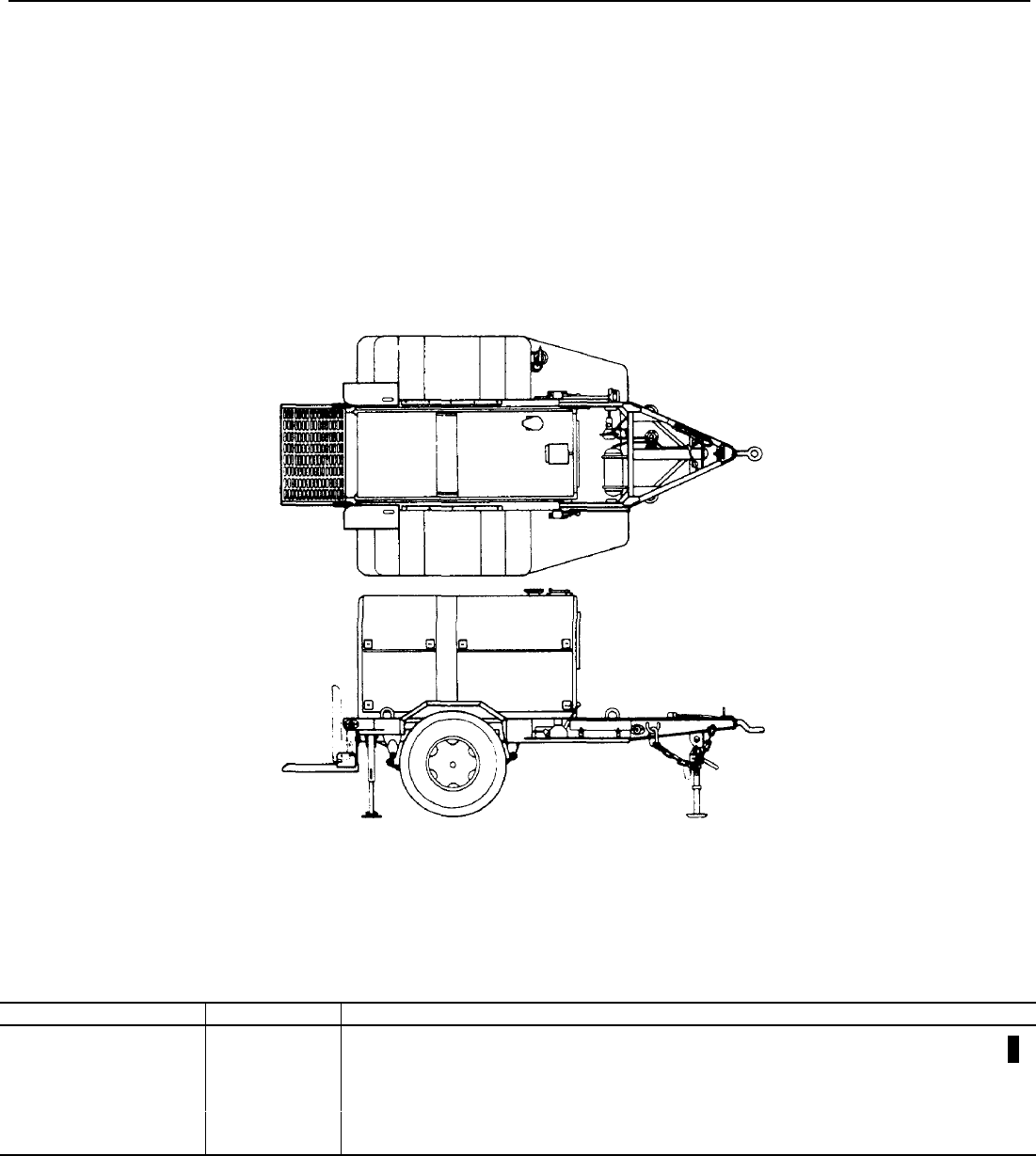
TM 5-6115-365-15
CHAPTER 23
GENERATOR SET PU-650B/G
Section I. DESCRIPTION AND DATA
23-1. Description
a. General. The trailer mounted generator set,
PU-650B/G, consists of a 60 KW, 50/60 Hertz, diesel
engine driven generator, mounted on a 2 1/2 ton, two
wheel modified trailer, Model M200A1 (Fig. 23-1).
b. Function. The generator set PU-650B/G is a
mobile power unit cable of furnishing 60 KW, 50/60
Hertz power.
c. Generator and Engine. For description,
operation and maintenance information, refer to
TM 5-6115-545-12.
d. Trailer. For description, lubrication, and
maintenance, refer to TM 9-2330-205-14.
Figure 23-1. Side and top view of generator set PU-650BIG.
23-2. Tabulated Data
Table 23-1 lists components for the PU-650B/G
generator set. Table 23-1. PU-650BI/G Components
NSN Qty Nomenclature
2330-00-331-2307 1Trailer, 2 1/2 Ton, Model M200A1
6115-00-118-1243 1Generator Set, PU-650B/G, 60 KW, 50/60 Hz, DED, Mdl. MEP-006A
4210-00-270-4512 1Fire Extinguisher
5975-00-878-3791 1Ground Rod Assembly
5120-00-251-4489 1Sledge Hammer
2910-00-066-1235 1Adapter Assembly
Change 11 23-1
TM 5-6115-365-15
Section II. OPERATING INSTRUCTIONS
WARNING
Wheels must be blocked, brakes set, and leg supports down in support position
before operating the equipment.
Never operate the generator set until it has been properly grounded. Electrical
defects in the load lines or equipment can cause death by electrocution when
contact is made with an ungrounded system.
Never operate the generator set in an inclosed area unless the exhaust gases are
piped to the outside. Inhalation of exhaust fumes will result in serious illness or
death.
23-3. Setting-Up Instructions
a. Leveling.
(1) Locate the trailer on as level a surface as
possible in order for the generator set to operate
efficiently.
(2) Set brakes and block wheels securely to
prevent any movement. Operate the hand brake at
weekly intervals to assure freedom of linkage.
(3) Pull leg supports down and adjust length
for firm contact with ground.
b. Grounding.
(1) The generator set must be grounded prior
to operation. The ground may be any of three methods,
depending on the location and terrain.
(a) A ground rod driven to a depth of 8
feet.
(b) An underground metallic water
piping system.
(c) A metal plate (9 sq. ft.) buried at a
depth of 4 feet.
(2) The ground lead must be No. 6 AWG
copper wire bolted or clamped to the rod, plate or piping
system.
(3) Connect the other end of the ground lead
to the generator set ground stud.
23-4. Starting
a.Perform the pre-starting procedures described in
paragraph 1-3.
b. Start the generator set as instructed in
TM 5-6115-545-12.
23-5. Stopping
Stop the generator set as instructed in
TM 5-6115-545-12.
23-6. Operation
Operate the generator set as instructed in
TM 5-6115-545-12.
¶U.S. GOVERNMENT PRINTING OFFICE: 1991 - 554-030/40122
23-2 Change 6

(1) (2) (3) (4) (5) (6) (7)
Source maintenance National Unit Quantity 15-day organizational Illustration
and recoverability Stock Description of incorpo- maint allowances
code Number issue rated (a) (b) (c) (d) (a) (b)
in unit Fig. Item
Source
Mainten-
nance
Recovera-
bility
1-5 6-20 21-50 51-100 No. No.
TM 5-6115-365-15
C3
Section III. ORGANIZATIONAL REPAIR PARTS
GROUP 01 - ENGINE
0106 - ENGINE LUBRICATING
SYSTEM
PA OZZ 5730-00-809-9703 ELBOW. OIL DRAIN EA 1
MS24519-9 (96906)
PA OZZ HOSE, OIL DRAIN EA 1
MIL-H-6000 (81349)
PA OZZ 4730-00-908-3194 CLAMP, HOSE: Oil drain EA 1
MS 35482-11 (96906)
GROUP 15 - FRAME, TOWING
ATTACHMENTS AND
DRAWBARS
1501 - FRAME ASSEMBLY
PA OZZ 5310-00-088-1251 NUT, SELF-LOCKING, HEXA- EA 3
GON: Hammer clip and bracket
mtg. MS51922-1 (96906)
PA OZZ 5310-00-809-4058 WASHER, FLAT: Hammer clip EA 3
and bracket
MS27183-10 (96906)
PA OZZ 5305-00-068-0502 SCREW, CAP, HEXAGON HEAD: EA 3
Hammer clip and bracket
MS90725-6 (96906)
XB OZZ CLPP, SPRING: Hammer EA 1
13214E1213-1 (97403)
PA OZZ 5340-00-999-6277 BRACKET ASSEMBLY, HAMMER EA 1
13214E1214 (97403)
PA OZZ 5310-00-080-8495 NUT, PLAIN, WING EA 2
MS35425-39 (96906)
PA OZZ 5310-00-582-5965 WASHER, LOCK EA 2
MS35338-44 (96906)
PA OZZ 5310-00-809-4058 WASHER, FLAT EA 2
MS27183-10 (96906)
XB OZZ PLATE, HOLDDOWN EA 1
13214E1216 (97403)
XB OZZ 6115-00-450-6593 BRACKET EA 1
13214E1215 (97403)
XB OZZ 5306-00-197-1552 BOLT, WELDING EA 2
MS51934-23 (96906)
PA OZZ 5120-00-203-4656 HAMMER EA 1
GGGH86 (81348)
XB OZZ 2510-00-947-9219 STEP, FRONT, ROAD SIDE EA 1
13214E1462 (97403)
XB OZZ 2510-00-947-7727 STEP, FRONT, CURB SIDE EA 1
13214E1461 (97403)
XB OZZ STEP, REAR, ROAD SIDE EA 1
13214E1261 (97403)
XB OZZ STEP, REAR, CURB SIDE EA 1
13214E1259 (97403)
XB OZZ 2510-00-924-8707 FENDER, CURB SIDE EA 1
13214E1263 (97403)
XB OZZ 2510-00-924-8697 FENDER, ROAD SIDE EA 1
13214E1264 (97403)
XB OZZ 2510-00-926-3517 PLATFORM EA 1
13214E1298 (97403)
PA OZZ 5305-00-225-8499 SCREW, CAP, HEXAGON HEAD: EA 48
Fender and step mtg.
MS90725-34 (96906)
PA OZZ 5310-00-087-0057 WASHER, FLAT: Fender, step EA 140
and bracket mtg.
MS27183-12 (96906)
Change 6 23-3
(1) (2) (3) (4) (5) (6) (7)
Source maintenance National Unit Quantity 15-day organizational Illustration
and recoverability Stock Description of incorpo- maint allowances
code Number issue rated (a) (b) (c) (d) (a) (b)
in unit Fig. Item
Source
Mainten-
nance
Recovera-
bility
1-5 6-20 21-50 51-100 No. No.
TM 5-6115-365-15
C3
1501 - FRAME ASSEMBLY
PA OZZ 5310-00-984-3806 - Continued EA 72
NUT, SELF-LOCKING, HEXA-
GON: Fender, step and bracket
mtg.
XB OZZ MS51922-9 (96906) EA 1
BRACKET, REAR STEP: Curbside
13214E1309-2 (97403)
PA OZZ 5305-00-269-3213 SCREW, CAP, HEXAGON HEAD: EA 6
Rear step bracket
MS90725-62 (96906)
PA OZZ 5310-00-950-1310 WASHER, FLAT: Rear step EA 6
bracket
MS27183-14 (96906)
PA OZZ 5310-00-087-4652 NUT, SELF-LOCKING, HEXA-
GON: Rear step bracket EA 6
MS51922-17 (96906)
XB OZZ BRACKET, REAR STEP: Road-
side EA 1
13214E1309-1 (97403)
PA OZZ 5305-00-225-8500 SCREW, CAP, HEXAGON HEAD: EA 10
Fender mtg.
MS90725-35 (96906)
XB OZZ SPACER, CHANNEL EA 2
13214E1267-1 (97403)
XB OZZ 9520-00-945-7542 CHANNEL, FRONT EA 1
13214E1268 (97403)
PA OZZ 5305-00-225-8503 SCREW, CAP, HEXAGON HEAD: EA 2
Channel mtg.
MS90725-39 (96906)
XB OZZ SPACER, FRONT STEP EA 12
13214E1267-2 (97403)
XB OZZ 9520-00-947-7219 CHANNEL, FRONT STEP EA 1
13214E1463 (97403)
XB OZZ 2510-00-923-1254 BRACKET, BRAKE EA 2
13214E1269 (97403)
XB OZZ BRACKET, BRAKE CABLE EA 2
13214E1270 (97403)
XB OZZ 5340-00-944-2691 STRAP, BRAKE CABLE EA 2
13214E1271 (97403)
XB OZZ 5340-00-989-3304 SPACER, BRAKE BRACKET EA 4
13214E1272 (97403)
XB OZZ 5340-00-999-6253 ANCHOR, PLATFORM EA 2
13214E1303 (97403)
XB OZZ 5340-00-087-7676 BRACKET, PLATFORM: LH EA 1
13214E1299 (97403)
XB OZZ 5340-00-999-6441 BRACKET, PLATFORM: RH EA 1
13214E1300 (97403)
PA OZZ 5305-00-042-6417 SCREW, CAP, HEXAGON HEAD: EA 6
Platform bracket
MS90725-113 (96906)
PA OZZ 5310-00-809-5998 WASHER, FLAT: Platform EA 6
bracket
MS27183-18 (96906)
PA OZZ 5310-00-225-6993 NUT, SELF-LOCKING, HEXA- EA 6
GON: Platform bracket
MS51922-33 (96906)
PA OZZ 5310-00-939-9204 SCREW, CAP, HEXAGON HEAD: EA 2
Platform mtg.
MS90725-187 (96906)
23-4 Change 6
(1) (2) (3) (4) (5) (6) (7)
Source maintenance National Unit Quantity 15-day organizational Illustration
and recoverability Stock Description of incorpo- maint allowances
code Number issue rated (a) (b) (c) (d) (a) (b)
in unit Fig. Item
Source
Mainten-
nance
Recovera-
bility
1-5 6-20 21-50 51-100 No. No.
TM 5-6115-365-15
C3
1501 - FRAME ASSEMBLY
- Continued
PA OZZ 5310-00-809-8533 WASHER, FLAT: Platform mtg. EA 4
MS27183-23 (96906)
PA OZZ 5310-00-067-6356 NUT, SELF-LOCKING: HEXA-
GON: Platform mtg. EA 2
MS51922-57 (96906)
XB OZZ 2510-00-948-3253 BRACKET, LIGHT EA 1
13214E1308 (97403)
PA OZZ SCREW, CAP, HEXAGON HEAD: EA 2
bracket mtg.
MS90725-8 (96906)
PA OZZ 5310-00-809-4058 WASHER, FLAT: Light bracket EA 2
mtg.
MS27183-10 (96906)
PA OZZ 5310-00-088-1251 NUT, SELF-LOCKING, HEXA-
GON: Light bracket mtg. EA 2
MS51922-1 (96906)
PA OZZ 5305-00-225-9081 SCREW, CAP, HEXAGON HEAD:
Front step EA 2
MS90725-36 (96906)
GROUP 18 - BODY, CAB, HOOD
AND HULL
1808 - BOXES, CARRYING
CASES
PA OZZ 5310-00-984-3806 NUT, SELF-LOCKING, HEXA-
GON: Accessory box mtg. EA 3
MS51922-9 (96906)
PA OZZ 5310-00-080-6004 WASHER. FLAT: Accessory box
mtg. EA 3
MS27183-13 (96906)
PA OZZ 5305-00-225-8498 SCREW, CAP, HEXAGON HEAD:
Accessory box mtg. EA 3
MS90725-33 (96906)
XB OZZ BOX, ACCESSORY EA 1
13214E1256 (97403)
XB OZZ HINGE, CONTINUOUS EA 1
MS35825-ID (69606)
XB OZZ RIVET, SOLID: Latch mtg. EA 8
MS20613-4PS (96906)
XB OZZ LATCH AND STRIKE ASSEMBLY EA 2
MS18015-1 (96906)
GROUP 22 - BODY CHASSIS
OR HULL
2202 - ACCESSORY ITEMS
XB OZZ 2910-00-066-1235 ADAPTER, FUEL DRUM EA 1
13211E7541 (97403)
XB OZZ PIPE, EXTENSION EA 1
13211E7542 (97403)
XB OZZ 4710-00-185-6948 PIPE, STAND EA 1
13211E7543 (97403)
XB OZZ WASHER, BRASS EA 1
13211E7544 (97403)
XB OZZ 5365-00-402-5125 RING, SEALING EA 1
13211E7546 (97403)
XB OZZ WASHER, STEEL EA 1
13200E6361 (97403)
XB OZZ 3740-00-902-1479 HEAD EA 1
13211E7548 (97403)
Change 6 23-5

(1) (2) (3) (4) (5) (6) (7)
Source maintenance National Unit Quantity 15-day organizational Illustration
and recoverability Stock Description of incorpo- maint allowances
code Number issue rated (a) (b) (c) (d) (a) (b)
in unit Fig. Item
Source
Mainten-
nance
Recovera-
bility
1-5 6-20 21-50 51-100 No. No.
TM 5-6115-365-15
C3
2202 - ACCESSORY ITEMS
- Continued
XB OZZ 3740-00-902-1481 CLAMP EA 1
13200E6363 (97403)
XB OZZ WASHER, RUBBER EA 1
13211E7547 (97403)
PA OZZ 5310-00-209-1239 WASHER, LOCK EA 2
MS35335-00 (96906)
PA OZZ 4730-00-277-5115 NIPPLE EA 1
AN816-5-4 (81352)
XB OZZ SCREW, SHOULDER EA 2
13211 E7545 (97403)
PA OZZ ROD, GROUND EA 2
MIL-R-11461 (81349)
2210 - DATA PLATES
PA OZZ SCREW, DRIVE: Identification
plate mtg. EA 4
MS21318-21 (96906)
XB OZZ PLATE, IDENTIFICATION EA 1
13216E7604-36 (97403)
XB OZZ PLATE, IDENTIFICATION: EA 1
Ground
13205E4918 (97403)
GROUP 40 - ELECTRIC MO-
TORS AND GENERATORS
4000 - MAJOR ASSEMBLAGE
PA OZZ 5310-00-269-4040 NUT, SELF-LOCKING, HEXA- EA 4
GON: Generator mtg.
MS51922-49 (96906)
PA OZZ 5310-00-823-8803 WASHER, FLAT: Generator mtg. EA 4
MS27183-21 (96906)
XB OZZ WASHER, BEVEL: Generator mtg. EA 4
13206E4482-3 (97403)
PA OZZ 5305-00-724-7222 SCREW, CAP, HEXAGON HEAD: EA 4
Generator mtg.
MS90728-164 (96906)
4019 - RADIO INTERFERENCE
SUPPRESSION
PA OZZ 5310-00-543-4717 NUT, PLAIN. WING: Ground EA 1
stud
MS35425-28 (96906)
PA OZZ WASHER, FLAT: Ground and EA 4
AN961-616S (81352)
PA OZZ 5310-00-187-2413 WASHER, FLAT: Ground Stud
(Optional) EA 4
AN961-616T (81352)
PA OZZ 5310-00-584-7995 NUT, PLAIN, HEXAGON:
Ground lead to stud EA 1
MS16203-27 (96906)
PA OZZ 5310-00-584-7996 NUT, PLAIN, HEXAGON: Stud EA 2
MS16203-39 (96906)
PA OZZ 5310-00-022-8847 WASHER. LOCK: Stud EA 2
MS35333-110 (96906)
XB OZZ 5307-00-722-9437 STUD, GROUND EA 1
13214E1223 (97403)
PA OZZ TERMINAL LUG: Ground
stud EA 1
MS20659-110 (96906)
23-6 Change 6
(1) (2) (3) (4) (5) (6) (7)
Source maintenance National Unit Quantity 15-day organizational Illustration
and recoverability Stock Description of incorpo- maint allowances
code Number issue rated (a) (b) (c) (d) (a) (b)
in unit Fig. Item
Source
Mainten-
nance
Recovera-
bility
1-5 6-20 21-50 51-100 No. No.
TM 5-6115-365-15
C3
Section III. ORGANIZATIONAL REPAIR PARTS
4019 - RADIO INTERFERENCE
SUPPRESSION - Continued
PA OZZ WIRE, ELECTRICAL: Ground EA 1
QQW343CLASSB, TYPE C,
XAR1
GROUP 76 - FIRE FIGHTING
EQUIPMENT COMPONENTS
7603 - FIRE EXTINGUISHERS
PA OZZ 4210-00-270-4512 EXTINGUISHER, FIRE EA 1
OE910 (81348)
PA OZZ 5310-00-087-4652 NUT, SELF-LOCKING, HEXA-
GON: Extinguisher bracket EA 4
MS51922-17 (96906)
PA OZZ 5310-00-080-6004 WASHER, FLAT: Extinguisher
bracket EA 4
MS27183-14 (96906)
PA OZZ 5305-00-984-5691 SCREW, MACHINE: Extinguisher EA 4
bracket
MS352067-311 (96906)
XB OZZ BRACKET, FIRE EXTINGUISHER EA 1
13214E1235 (97403)
Change 6 23-7

(1) (2) (3) (4) (5) (6)
30-day DS
(7)
30-Day GS (7)
Source maintenance National Unit Quantity maint. ALW. maint. ALW Illustration
and recoverability Stock Description of incorpo-
code Number issue rated (a) (b) (c) (a) (b) (c) (a)
in unit Fig. Item
Source
Mainten-
nance
Recovera-
bility
1-20 21-50 51-100 1-20 21-50 51-100 No. No.
TM 5-6115-365-15
C3
Section IV. DIRECT SUPPORT, GENERAL SUPPORT, AND DEPOT PARTS
GROUP 01 - ENGINE
0106 - ENGINE LUBRICATING
SYSTEM
PA OZZ 4730-00-809-9703 ELBOW, OIL DRAIN EA 1
MS24519-9 (96906)
PA OZZ HOSE, OIL DRAIN EA 1
MIL-H-6000 (81349)
PA OZZ 4730-00-908-3194 CLAMP, HOSE: Oil drain EA 1
MS35482-11 (96906)
GROUP 15 - FRAME,
TOWING ATTACHMENTS
AND DRAWBARS
1501 - FRAME ASSEMBLY
PA OZZ 5310-00-088-1251 NUT, SELF-LOCKING, HEXA- EA 3
GON: Hammer clip and bracket
mtg.
MS51922-1 (96906)
PA OZZ 5310-00-809-4058 WASHER, FLAT: Hammer clip EA 3
and bracket
MS27183-10 (96906)
PA OZZ 5305-00-068-0502 SCREW, CAP HEXAGON HEAD: EA 3
Hammer clip and bracket
MS90725-6 (96906)
XB OZZ CLIP, SPRING: Hammer EA 1
13214E1213-1 (97403)
PA OZZ 5340-00-999-6277 BRACKET ASSEMBLY, HAMMER EA 1
13214E1214 (97403)
PA OZZ 5310-00-080-8495 NUT, PLAIN, WING EA 2
MS35425-39 (96906)
PA OZZ 5310-00-582-5965 WASHER, LOCK EA 2
MS3533844 (96906)
PA OZZ 5310-00-809-4058 WASHER, FLAT EA 2
MS27183-10 (96906)
XB OZZ PLATE, HOLDDOWN EA 1
13214E1216 (97403)
XB OZZ 6115-00-450-6593 BRACKET EA 1
13214E1215 (97403)
XB OZZ 5306-00-197-1552 BOLT, WELDING EA 2
MS51934-23 (96906)
PA OZZ 5120-00-203-4656 HAMMER EA 1
GGGH86 (81348)
XB OZZ 2510-00-947-9219 STEP, FRONT ROADSIDE EA 1
13214E1462 (97403)
XB OZZ 2510-00-947-7727 STEP, FRONT, CURBSIDE EA 1
13214E1461 (97403)
XB OZZ STEP, REAR, ROADSIDE EA 1
13214E1261 (97403)
XB OZZ STEP, REAR, CURBSIDE EA 1
13214E1259 (97403)
XB OZZ 2510-00-924-8707 FENDER, CURBSIDE EA 1
13214E1263 (97403)
XB OZZ 2510-00-924-8697 FENDER, ROADSIDE EA 1
13214E1264 (97403)
XB OZZ 2510-00-92i-3517 PLATFORM EA 1
13214E1298 (97403)
PA OZZ 5305-00-225-8499 SCREW, CAP, HEXAGON HEAD: EA 48
Fender and step mtg.
MS90725-34 (96906)
23-8 Change 6

(1) (2) (3) (4) (5) (6)
30-day DS
(7)
30-Day GS (7)
Source maintenance National Unit Quantity maint. ALW. maint. ALW Illustration
and recoverability Stock Description of incorpo-
code Number issue rated (a) (b) (c) (a) (b) (c) (a)
in unit Fig. Item
Source
Mainten-
nance
Recovera-
bility
1-20 21-50 51-100 1-20 21-50 51-100 No. No.
TM 5-6115-365-15
C3
PA OZZ 5310-00-087-0057 WASHER, FLAT: Fender, step EA 140
and bracket mtg.
MS27183-12 (96906)
PA OZZ 5310-00-984-3806 NUT, SELF-LOCKING HEXA-
GON: Fender, step and bracket EA 72
mtg.
MS51922-9 (96906)
XB OZZ BRACKET, REAR STEP: Curb- EA 1
side
13214E1309-2(97403)
PA OZZ 5305-00-269-3213 SCREW, CAP, HEXAGON HEAD: EA 6
Rear step bracket
MS90725-62 (96906)
PA OZZ 5310-00-950-1310 WASHER, FLAT: Rear step brack- EA 6
et
MS27183-14 (96906)
PA OZZ 5310-00-087-4652 NUT, SELF-LOCKING, HEXA- EA 6
GON: Rear step bracket
MS51922-17 (96906)
XB OZZ BRACKET, REAR STEP: Road- EA 1
side
13214F1309-1 (97403)
PA OZZ 5305-00-225-8500 SCREW, CAP, HEXAGON HEAD: EA 10
Fender mtg.
MS90725-35 (96906) EA 2
XB OZZ SPACER, CHANNEL
13214E1267-1 (97403) EA 1
XB OZZ 9520-00-945-7542 CHANNEL, FRONT
13214E1268 (97403)
PA OZZ 5305-00-225-8503 SCREW, CAP, HEXAGON HEAD: EA 12
Channel mtg.
MS90725-39 (96906)
XB OZZ SPACER, FRONT STEP EA 2
13214E1267-2 (97403)
XB OZZ 9520-00-947-7219 CHANNEL, FRONT STEP EA 1
13214E1463 (97403)
XB OZZ 2510-00-923-1254 BRACKET, BRAKE EA 2
13214E1269 (97403)
XB OZZ BRACK ET, BRAKE CABLE EA 2
13214E1270 (97403)
XB OZZ 5340-00-944-2691 STRAP, BRAKE CABLE EA 2
13214E1271 (97403)
XB OZZ 5340-00-989-3304 SPACER, BRAKE BRACKET EA 4
13214F1272 (97403)
XB OZZ 5340-00-999-6253 ANCHOR, PLATFORM EA 2
13214E1303 (97403)
XB OZZ 5340-00-087-7676 BRACKET, PLATFORM: LH EA 1
13214E1299 (97403)
XB OZZ 5340-00-999-6441 BRACKET, PLATFORM: RH EA 1
13214E1300 (97403)
PA OZZ 5305-00-042-6417 SCREW, CAP, HEXAGON HEAD:
Platform bracket EA 6
MS90725-113 (96906)
PA OZZ 5310-00-809-5998 WASHER, FLAT: Platform brack-
et EA 6
MS27183-18 (96906)
PA OZZ 5310-00-225-6993 NUT, SELF-LOCKING, HEXA-
GON: Platform bracket EA 6
MS51922-33 (96906)
Change 6 23-9
(1) (2) (3) (4) (5) (6)
30-day DS
(7)
30-Day GS (7)
Source maintenance National Unit Quantity maint. ALW. maint. ALW Illustration
and recoverability Stock Description of incorpo-
code Number issue rated (a) (b) (c) (a) (b) (c) (a)
in unit Fig. Item
Source
Mainten-
nance
Recovera-
bility
1-20 21-50 51-100 1-20 21-50 51-100 No. No.
TM 5-6115-365-15
C3
PA OZZ 5305-00-939-9204 SCREW, cap, HEXAGON HEAD: EA 2
Platform mtg.
MS90725-187 (96906)
PA OZZ 5310-00-809-8533 WASHER, FLAT: Platform mtg. EA 4
MS27183-23 (96906)
PA OZZ 5310-00-067-6356 NUT, SELF-LOCKING HEXA- EA 2
GON: Platform mtg.
MS51922-57 (96906) EA 1
XB OZZ 2510-00-948-3253 BRACKET, LIGHT
13214E1308 (97403)
PA OZZ SCREW, CAP, HEXAGON HEAD: EA 2
Light bracket mtg.
MS90725-8 (96906)
PA OZZ 5310-00-809-4058 WASHER, FLAT: Light bracket EA 2
mtg.
MS27183-10 (96906)
PA OZZ 5310-00-088-1251 NUT, SELF-LOCKING, HEXA- EA 2
GON: Light bracket mtg.
MS51921-1 (96906)
PA OZZ 5305-00-225-9081 SCREW, CAP, HEXAGON HEAD: EA 2
Front step
MS90725-36 (96906)
GROUP 18 - BODY CAB, HOOD
AND HULL
1808 - BOXES, CARRYING
CASES
PA OZZ 5310-00-984-3806 NUT, SELF-LOCKING, HEXA- EA 3
GON: Accessory box mtg.
MS51922-9 (96906)
PA OZZ 5310-00-080-6004 WASHER, FLAT: Accessory box EA 3
mtg.
MS27183-13 (96906)
PA OZZ 5305-00-225-8498 SCREW, CAP, HEXAGON HEAD: EA 3
Accessory box mtg.
MS90725-33 (96906)
XB OZZ BOX, ACCESSORY EA 1
13214E1256 (97403)
XB OZZ HINGE, CONTINUOUS EA 1
MS35825-1D (96906)
XB OZZ RIVET, SOLID: Latch mtg. EA 8
MS20613-4PS (96906)
XB OZZ LATCH AND STRIKE EA 2
ASSEMBLY
MS18015-1 (96906)
1810 - CARGO BODY
XB FFD 2330-00-331-2307 TRAILER EA 1
13214E1257 (97403)
XB FFD CHASSIS EA 1
13214E1258 (97403)
GROUP 22 - BODY CHASSIS OR
HULL, AND ACCESSORY ITEMS
2202 - ACCESSORY ITEMS
XB OZZ 2910-00-066-1235 ADAPTER. FUEL RRUM EA 1
13211E7541 (97403)
XB OZZ PIPE, EXTENSION EA 1
13211E7542 (97403)
XB OZZ 4710-00-185-6948 PIPE, STAND EA 1
13211E7543 (97403)
23-10 Change 6

(1) (2) (3) (4) (5) (6)
30-day DS
(7)
30-Day GS (7)
Source maintenance National Unit Quantity maint. ALW. maint. ALW Illustration
and recoverability Stock Description of incorpo-
code Number issue rated (a) (b) (c) (a) (b) (c) (a)
in unit Fig. Item
Source
Mainten-
nance
Recovera-
bility
1-20 21-50 51-100 1-20 21-50 51-100 No. No.
TM 5-6115-365-15
C3
2202-ACCESSORY ITEMS-Cont
XB OZZ WASHER, BRASS EA 1
13211E7544 (97403)
XB OZZ 5365-00-402-5125 RING, SEALING EA 1
13211E7546 (97403)
XB OZZ WASHER, STEEL EA 1
13200E6361 (97403)
XB OZZ 3740-00-902-1479 HEAD EA 1
13211E7548 (97403)
XB OZZ 3740-00-902-1481 CLAMP EA 1
13200E6363 (97403)
XB OZZ WASHER, RUBBER EA 1
13211E7547 (97403)
PA OZZ 5310-00-209-1239 WASHER, LOCK EA 2
MS35335-60 (96906)
PA OZZ 4730-00-277-5115 NIPPLE EA 1
AN816-5-4 (81352)
XB OZZ SCREW, SHOULDER EA 2
13211E7545 (97403)
PA OZZ ROD, GROUND EA 2
MIL-R-11461 (81349)
2210 - DATA PLATES
PA OZZ SCREW, DRIVE: Identification EA 4
plate mtg.
MS21318-21 (96906)
XB OZZ PLATE, IDENTIFICATION EA 1
13216E7604-36 (97403)
XB OZZ PLATE, IDENTIFICATION: EA 1
Ground
13205E4918 (97403)
GROUP 40 - ELECTRIC MO-
TORS AND GENERATORS
4000 - MAJOR ASSEMBLAGE
PA OZZ 5310-00-269-4040 NUT, SELF-LOCKING, HEXA- EA 4
GON: Generator mtg.
MS51922-49 (96906)
PA OZZ 5310-00-823-8803 WASHER, FLAT: Generator mtg. EA 4
MS27183-21 (96906)
XB OZZ WASHER, BEVEL: Generator mtg. EA 4
13206E448-2-3 (97403)
PA OZZ 5305-00-724-7222 SCREW, CAP, HEXAGON HEAD: EA 4
Generator mtg.
MS90728-164 (96906) EA 1
PA FFD 6115-00-118-1243 GENERATOR, DIESEL ENGINE
MIL-C-52884-8 (81349)
4019 - RADIO INTERFERENCE
SUPPRESSION
PA OZZ 5310-00-543-4717 NUT, PLAIN, WING: Ground EA 1
stud
MS35425-28 (96906) EA 4
PA OZZ WASHER, FLAT: Ground stud
AN961-616S (81352)
PA OZZ 5310-00-187-2413 WASHER, FLAT: Ground stud EA 4
(Optional)
AN961-616T (81352)
PA OZZ 5310-00-584-7995 NUT, PLAIN, HEXAGON: Ground EA 1
lead to stud
MS16203-27 (96906)
PA OZZ 5310-00-584-7996 NUT, PLAIN, HEXAGON: Stud EA 2
MS16203-39 (96906)
Change 6 23-11
(1) (2) (3) (4) (5) (6)
30-day DS
(7)
30-Day GS (7)
Source maintenance National Unit Quantity maint. ALW. maint. ALW Illustration
and recoverability Stock Description of incorpo-
code Number issue rated (a) (b) (c) (a) (b) (c) (a)
in unit Fig. Item
Source
Mainten-
nance
Recovera-
bility
1-20 21-50 51-100 1-20 21-50 51-100 No. No.
TM 5-6115-365-15
C3
4019-RADIO INTERFERENCE
SUPPRESSION-Continued
PA OZZ 5310-00-022-8847 WASHER, LOCK: Stud EA 2
MS35333-110 (96906)
XB OZZ 5307-00-722-9437 STUD, GROUND EA 1
PA OZZ 13214E1223 (97403)
PA OZZ TERMINAL, LUG: Ground stud EA 1
MS20659-110 (96906)
PA OZZ WIRE, ELECTRICAL: Ground EA I
QQW343CLASSB, TYPE C.
XAR1
GROUP 76 - FIRE FIGHTING
EQUIPMENT COMPONENTS
7603 - FIRE EXTINGUISHERS
PA OZZ 4210-00-270-4512 EXTINGUISHER, FIRE: EA 1
OE910 (81348)
PA OZZ 5310-00-087-4652 NUT, SELF-LOCKING, HEXA- EA 4
GON: Extinguisher bracket
MS51922-17 (96906)
PA OZZ 5310-00-080-6004 WASHER, FLAT: Extinguisher EA 4
bracket
MS27183-14 (96906)
PA OZZ 5305-00-984-5691 SCREW., MACHINE: Extinguisher EA 4
bracket
MS35206-311 (96906)
XB OZZ BRACKET, FIRE EXTINGUISH- EA 1
ER
13214E1235 (97403)
23-12 Change 6

TM 5-6115-365-15
APPENDIX A
REFERENCES
A-1. Fire Protection
TB 5-4200-200-10 Hand Portable Fire Extinguishers
Approved for Army Users
A-2. Lubrication
C9100IL Fuels, Lubricants, Oils, and Waxes
Refer to appropriate Lubrication Orders and Manuals listed in respective chapters for lubrication instructions
applicable.
A-3. Operating Instructions
TM 5-766 Electric Power Generators in the Field
Refer to appropriate manuals listed in respective chapters for operating instructions applicable to generator sets.
A-4. Maintenance
TM 5-764 Electric Motor and Generator Repair
TM 9-6140-200-15 Operation and Organizational, field, and depot maintenance: Storage batteries,
lead-acid type
TM 11-483 Radio Interference Suppression
DA PAM 738-750 The Army Maintenance Management System
A-5. Shipment and Storage
SB 38-100 Army Preservation, Packing and Marking Materials, Supplies, and Equipment
TM 38-230-1 Preservation, packing, and packing of military supplies and equipment (Vol 1).
TM 740-90-1 Administrative Storage of Equipment
A-6. Demolition
TM 750-244-3 Procedures for destruction of equipment to prevent enemy use (Mobility
equipment Command)
Change 8 A-1/(A-2 blank)

TM 5-6115-365-15
C4
APPENDIX B
BASIC ISSUE ITEMS LIST AND ITEMS
TROOP INSTALLED OR AUTHORIZED
Section I. INTRODUCTION
B1. Scope
This appendix lists items required by the operator for
operation of the generator set.
B-2. General
This list is divided into the following sections:
a. Basic Issue Items List - Section II. Not
applicable.
b. Items Troop Installed or Authorized List Section
III. A list of items in alphabetical sequence, which at the
discretion of the unit commander may accompany the
generator set. These items are not subject to turn-in
with the generator set when evacuated.
B-3. Explanation of Columns
The following provides an explanation of columns in the
tabular list of items troop installed or authorized, section
III. a. Source, Maintenance, and Recoverability
Code(s) (SMR):
(1) Source Code. This code indicates the
source for the listed item. Source codes are:
Code Explanation
PRepair parts, special tools, and test equipment
supplied from GSA/DSA or Army supply
system and authorized for use at indicated
maintenance levels.
P2 Repair parts, special tools, and test equipment
which are procured and stocked for insurance
purposes be cause the combat or military
essentiality of the end item dictates that a
minimum quantity be available in the supply
system.
(2) Maintenance code. This code indicates the
lowest level of maintenance authorized to
install the listed item. The maintenance level
code is:
Code Explanation
CCrew/Operator
(3) Recoverability code. This code indicates
whether unserviceable items should be returned for
recovery or salvage. Items not coded are non-
recoverable. Recoverability codes are:
Code Explanation
RApplied to repair parts (assemblies and
components), special tools, and test
equipment-which are considered
economically reparable at direct and general
support maintenance levels.
SRepair parts, special tools, test equipment,
and assemblies which are economically
reparable at DSU and GSU activities and
which normally are furnished by supply on
an exchange basis.
b. Federal Stock Number. This column indicates
the Federal stock number assigned to the item. This
number will be used for requisitioning purposes.
c. Description. This column indicates the Federal
item name and any additional description of the item
required.
d. Unit of Measure (U/M). A 2-character alphabetic
abbreviation indicating the amount or quantity of the item
upon which the allowances are based: e.g., ft, ea, etc.
e. Quantity Authorized. This column indicates the
quantity of the item authorized to be used with the
equipment.
B-1

TM 5-6115-365-15
Section III. ITEMS TROOP INSTALLED OR AUTHORIZED LIST
(1) (2) (3) (4) (5)
Description Unit Qty auth
SMR Federal stock Ref. No. & Mfr Usable of
code Number code on code meas
PC 2910-066-1235 ADAPTER, Drum ea 1
PC 7520-559-9618 CASE, Maintenance and operation manuals. ea 1
PC 5935-00-258-9156 CONNECTOR, Plug ea 1
PC* 4210-270-4512 EXTINGUISHER, Fire ea 1
PC 4210-555-8837 EXTINGUISHER, Fire ea 1
PC 4720-021-3320 HOSE ASSY, Auxiliary fuel ea 1
PC 5975-878-3791 ROD ASSY, Ground ea 1
PC 5120-01-013-1676 HAMMER, SLIDE, Ground ea 1
*Applies to PU-401/M, FSN 6115-823-2217
PU-402/M, FSN 6115-722-3760
PU-406/M, FSN 6115-738-6342
PU-495/G, FSN 6115-823-2218
PU-551/G, FSN 6115-889-1307
PU-625/G, FSN 6115-873-3915
P U.S. GOVERNMENT PRINTING OFFICE: 1991 554-123/20091
B-2 Change 10

TM 5-6115-365-15
APPENDIX C
MAINTENANCE
Section I. INTRODUCTION
C-1. General
a. This section provides a general explanation of
all maintenance and repair functions authorized at
various maintenance levels.
b. Section II designates overall responsibility for
the performance of maintenance functions on the
identified item or component. The implementation of the
maintenance functions upon the end item or component
will be consistent with the assigned maintenance
functions.
c. Section III contains supplemental instructions,
explanatory notes and/or illustrations required for a
particular maintenance function.
C-2. Explanation of Columns in Section II
a. Group Number. The functional group is a
numerical group set up on a functional basis. The
applicable functional grouping indexes are listed on the
MAC in the appropriate numerical sequence.
b. Functional Group. This column contains a brief
description of the components of each functional group.
c. Maintenance Functions. This column lists the
various maintenance functions (A through K) and
indicates the lowest maintenance level authorized to
perform these functions. The symbol designations for
the various maintenance levels are as follows:
C - Operator or crew
O - Organizational maintenance
F - Direct support maintenance
H - General support maintenance
D - Depot maintenance
The maintenance functions are defined as follows:
A - INSPECT. To determine serviceability of an
item by comparing its physical, mechanical, and
electrical characteristics with established standards.
B - TEST. To verify serviceability and to detect
electrical or mechanical failure by use of test equipment.
C - SERVICE. To clean, to preserve, to charge, to
paint, and to add fuel, lubricants, cooling agents, and air.
D - ADJUST. To rectify to the extent necessary to
bring into proper operating range.
E - ALIGN. To adjust specified variable elements
of an item to bring to optimum performance.
F - CALIBRATE. To determine the corrections to
be made in the readings of instruments or test
equipment used in precise measurement. Consists of
the comparisons of two instruments, one of which is a
certified standard of known accuracy, to detect and
adjust any discrepancy in the accuracy, of the instrument
being compared with the certified standard.
G - INSTALL. To set up for use in an operational
environment such as an emplacement, site, or vehicle.
H - REPLACE. To replace unserviceable items
with serviceable assemblies, subassemblies, or parts.
I - REPAIR. To restore an item to serviceable
condition. This includes, but is not limited to, inspection,
cleaning, preserving, adjusting, replacing, welding,
riveting, and strengthening.
J - OVERHAUL. To restore an item to a
completely serviceable condition as prescribed by
maintenance serviceability standards using the Inspect
and Repair Only as Necessary (IROAN) technique.
K - REBUILD. To restore an item to a standard as
nearly as possible to original or new condition in
appearance, performance, and life expectancy. This is
accomplished through complete disassembly of the item,
inspection of all parts or components, repair or
replacement of worn or unserviceable elements (items)
using original manufacturing tolerances and
C-1
TM 5-6115-365-15
C3
specifications and subsequent reassembly of the item.
d. Tools and Equipment. This column is not
applicable.
e. Remarks. This column is provided for
referencing by code the remarks (section III) pertinent to
the maintenance functions.
C-3. Explanation of Columns in Section III.
a. Reference Code. This column consists of two
letters separated by a dash, both of which are
references to section II.
The first letter references column 5 and the second letter
references a maintenance function, column 3, A through
K.
b. Remarks. This column lists information
pertinent to the maintenance function being performed,
as indicated on the MAC, section II.
Change 3, C-2
(1) (2) (3)
Maintenance Functions
(4) (5)
ABCDEFGHIJK
Group No.
Functional Group
Inspect
Test
Service
Adjust
Align
Calibrate
Install
Replace
Repair
Overhaul
Rebuild
Tools and
Equipment Remarks
Section II. MAINTENANCE ALLOCATION CHART TM 5-6115-365-15
C3
01 ENGINE
0100 Engine Assembly CF F A
03 FUEL SYSTEM
0306 Tanks, Lines, Fittings O O B
06 ELECTRICAL SYSTEM
0608 Miscellaneous Trailer Wiring O O
15 FRAME
1501 Frame Assembly D
1507 Leveling Jacks O O F
18 BODY
1808 Stowage Racks, Boxes, O O
Cable Reels
1810 Cargo Body D D
22 BODY ACCESSORY ITEMS
2201 Canvas Items O O F
2202 Accessory Items O O
2210 Data Plates O O
29 AUXILIARY GENERATOR
AND ENGINE
2901 Generator Assembly CF F C
2916 Engine Lubrication System CO
C-2.1
(1) (2) (3)
Maintenance Functions
(4) (5)
ABCDEFGHIJK
Group No.
Functional Group
Inspect
Test
Service
Adjust
Align
Calibrate
Install
Replace
Repair
Overhaul
Rebuild
Tools and
Equipment Remarks
TM 5-6115-365-15
C3
2941 Engine Exhaust O O
40 ELECTRIC GENERATORS
4000 Generator Set F F C
42 ELECTRICAL EQUIPMENT
4202 Electrical Controls F F
4216 Miscellaneous Wiring and O O
Fittings
C-2.2

TM 5-6115-365-15
C3
Section III. REMARKS
Reference Remarks
Code
A-I Refer to applicable Generator TM for engine replacement and refer to
applicable Engine TM for engine repair.
B-H Applies to PU-375B/G, PU-625/G, PU-628G, PU-629/G, PU-631/G, and
PU-656/G
C-H Remove and install the generator and engine as a single unit.
C-3

TM 5-6115-365-15
C3
INDEX
Paragraph Page
Introduction ..................................................................................1-1 1-1
PU-236/G ....................................................................................8-1 8-1
PU-236A/G...................................................................................8-1 8-1
PU-236B/G...................................................................................7-1 7-1
PU-253/U. ................................................................................13-1 13-1
PU-253A/U.................................................................................13-1 13-1
PU-304C/MPQ-4.........................................................................16-1 16-1
PU-332/G...................................................................................11-1 11-1
PU-332A/G ................................................................................11-1 11-1
PU-375/G...................................................................................14-1 14-1
PU-375A/G.................................................................................14-1 14-1
PU-375B/G.................................................................................17-1 17-1
PU-401/M.....................................................................................9-1 9-1
PU-402/M.....................................................................................5-1 5-1
PU-406/M.....................................................................................5-1 5-1
PU-409/M.....................................................................................6-1 6-1
PU-409A/M...................................................................................6-1 6-1
PU-495/G...................................................................................10-1 10-1
PU-551/G...................................................................................15-1 15-1
PU-564A/G.................................................................................12-1 12-1
PU-564B/G.................................................................................12-1 12-1
PU-617/M.....................................................................................2-1 2-1
PU-618/M ....................................................................................4-1 4-1
PU-619/M.....................................................................................3-1 3-1
PU-620/M.....................................................................................4-1 4-1
PU-625/G...................................................................................22-1 22-1
PU-628/G...................................................................................18-1 18-1
PU-629/G...................................................................................19-1 19-1
PU-631/G...................................................................................20-1 20-1
PU-656/G...................................................................................21-1 21-1
INDEX 1
TM 5-6115-365-15
By Order of the Secretary of the Army: HAROLD K. JOHNSON,
General, United States Army,
Official: Chief of Staff.
J.C. LAMBERT,
Major General, United States Army,
The Adjutant General.
Distribution:
Active Army:
USASA (2)
ACSI (1)
DCSLOG (1)
CNGB (1)
TSG (1)
CofEngrs (3)
CC-E (1)
Dir of Trans (1)
CofSptS (1)
USAMB (1)
USACDCARTYA (2)
USACDCARMA (2)
USAIB (2)
USA AD Bd (2)
USAAESWBD (2)
USA Avn Bd (2)
USCONARC (3)
OS Maj Comd (6) except
USASETAF (2)
USARJ (1)
USAMOCOM (2)
USASMC (1)
MDW (1)
Armies (2)
Corps (2)
USAC (1)
Div (2)
Engr Bde (1)
USMA (2)
Svc Colleges (2)
Br Svc Sch (2)
USACDCEC (10)
Gen Dep (10)
Engr Dep (10)
Army Dep (2)
USA Tml Comd (2)
Army Tml (1)
Div Engr (2)
Engr Dist (2)
USAMEC (46)
USAECFB (5)
USAREUR Engr Proc Cen (2)
USAREUR Engr Sup Cen Agcy (10)
Engr Fld Maint Shops (2)
Ft Knox Fld Maint Shops (10)
Fld Comd, DASA (8)
AMS (3)
USAREURCOMZ (2)
MAAG (1)
JBUSMC (1)
USA Engr RD Lab (3)
Units org under fol TOE
(2 copies each UNOINDC) :
1-7 6-35
1-37 6-36
1-55 6-700
1-58 6-701
1-75 6-575
1-78 6-576
1-100 7-11
1-101 7-12
1-107 7-42
1-127 8-35
1-137 8-36
1-207 8-122
1-252 8-126
1-256 8-137
1-102 8-187
1-307 8-551
3-52 8-581
5-25 8-590
5-26 8-667
5-35 8-902
5-36 8-903
5-45 9-12
5-46 9-86
5-52 9-87
5-112 9-227
5-145 9-247
5-146 10-17
5-155 10-22
5-156 10-77
5-237 (5) 10-105
5-262 (5) 10-106
5-266 10-107
5-267 (1) 10-127
5-279 10-201
5-500 (BB, GD, 10-202
6-401 10-206
6-555 10-337
6-556 10-349
6-557 10-407
TM 5-6115-365-15
10-417 11-51 29-127 44-237
10-445 11-52 29-136 44-535
10-446 11-227 29-137 44-536
10-447 11-500 (TM) 29-139 44-537
10-448 12-56 29-202 51-15
10-458 12-57 29-206 51-16
10-467 17-42 29-215 55-6
10-475 19-252 29-216 56-11
10-476 19-256 29-217 55-12
10-477 29-1 30-5 55-16
10-500 (KK, KL, 29-5 30-6 55-62
KM) 29-6 30-7 55-66
10-521 29-15 30-25 55-89
10-536 29-16 30-26 55-116
11-38 29-21 30-27 55-126
11-45 29-25 30-28 556-131
11-46 29-26 30-29 55-202
11-55 29-35 30-500 (AC, AD, 55-225
11-57 29-36 AF, AG, FA, FB, 55-227
11-66 29-45 FC, JA, JB) 55-260
11-117 29-46 37-42 55-302
11-127 29-51 37-51 55-458
11-155 29-55 37-61 55-459
11-156 29-61 44-2 55-500 (GF, LA,
11-157 29-102 44-12 LB, LC, LF)
11-158 29-116 44-85 57-42
11-165 29-118 44-86 67-42
11-166 29-119 44-235
11-237 29-126 44-236
NG: State AG (3).
USAR: Same as active Army except allowance is one copy to each unit.
For explanation of abbreviations used, see AR 320-50.
P U.S. GOVERNMENT PRINTING OFFICE: 1987--2 0 1 -4 2 1 / 7 1 0 9 2
PIN: 025622-011
