02 Robot1 Assembly Instructions
User Manual:
Open the PDF directly: View PDF ![]() .
.
Page Count: 11
Lab 02 Robot 1 Assembly Instructions
16-384
Carnegie Mellon University
Prof. Howie Choset
1

1 Bill of Materials
Table 1: Bill of Materials
No. Desciption Quantity
1 Hebi X Series Actuator 2
2 1 inch or 25 mm 80/20 T-Slot Aluminum Extrusion 1
3 Clamp 2
4 Hebi T-Slot Adapter (PM-2156-25) 1
5 M5x0.8x10 Flat-Head Socket Head Cap Screw 4
6 80/20 T-Nut for 1 inch or 25 mm T-Slot Extrusion 4
7 80/20 Screw for 1 inch or 25 mm T-Slot Extrusion 4
8 M5x0.8x16 Screw 12
9 Hebi Output Tube Adapter (A-2038-01) 2
10 M5x0.8x10 Screw 12
11 Hebi Housing Tube Mount (A-2039-01) 1
12 M5x0.8x8 Screw 6
13 0.55 meter x 32 mm Diameter Tube 1
14 0.3 meter x 32 mm Diameter Tube 1
15 Ethernet Cable 4
16 18-50V AC-DC Converter and Wall Adapter 1
17 Emergency Stop 1
18 Hebi Power Cables As Needed
19 Hebi Male-to-Male Power Adapter As Needed
20 Hebi Power Cable Splitter 1
21 Internet Router 1
3

2 Assembly Steps
2.1 Mechanical Assembly
5
4
1
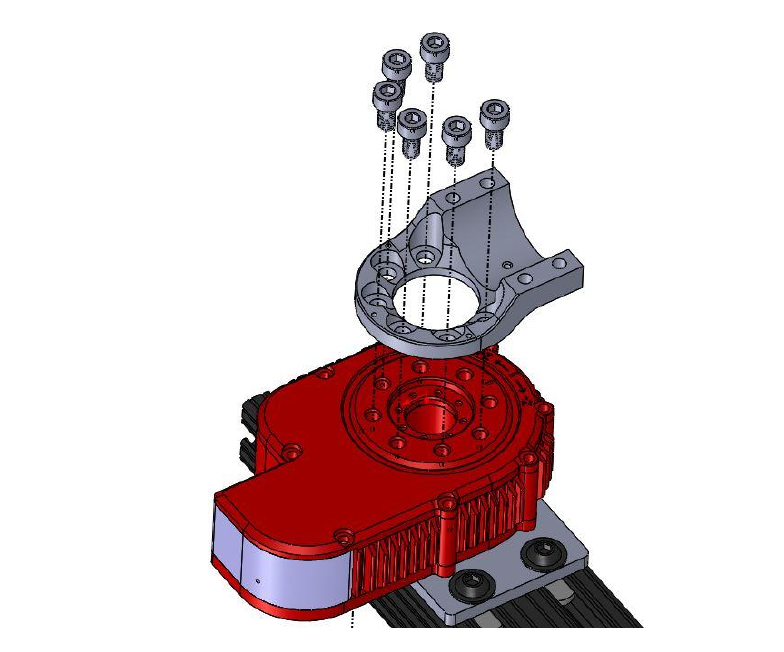
Figure 1: Attaching the a Hebi Actuator to the T-Slot Adapter
4

5
9
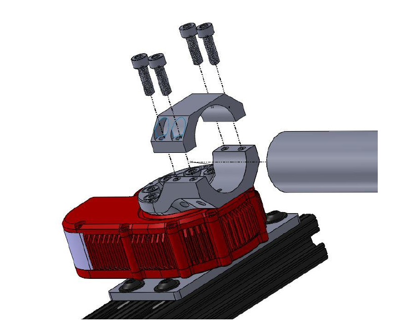
Figure 3: Attaching the Bottom Half of an Output Tube Adapter
6
5
9
8
13
9
Figure 4: Attaching the Robot’s First Link
7
12
11
1
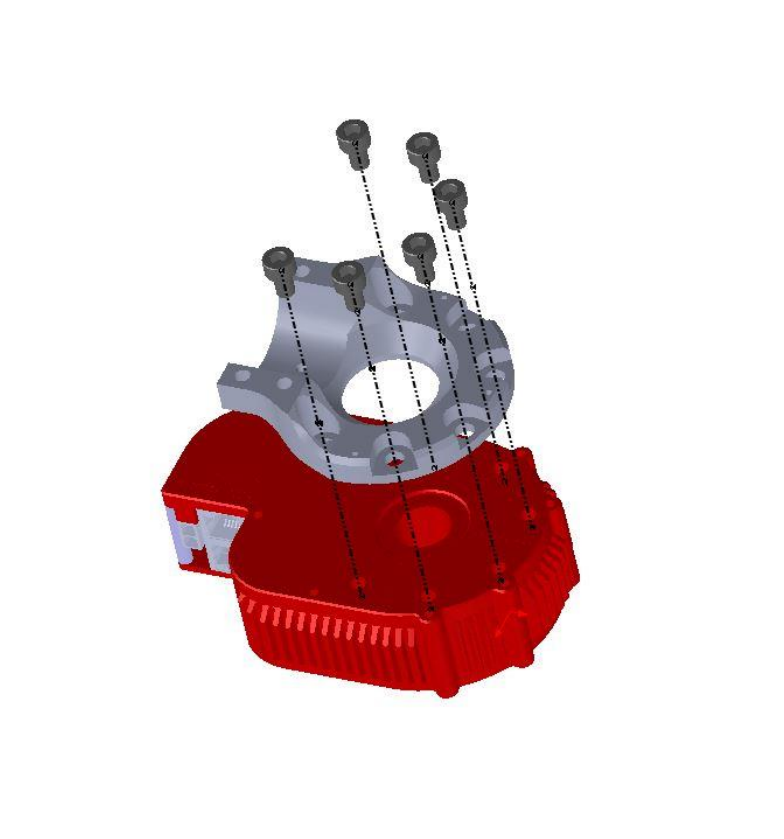
Figure 5: Attaching the Tube Mount to the Second Hebi Actuator
8
8
9
14
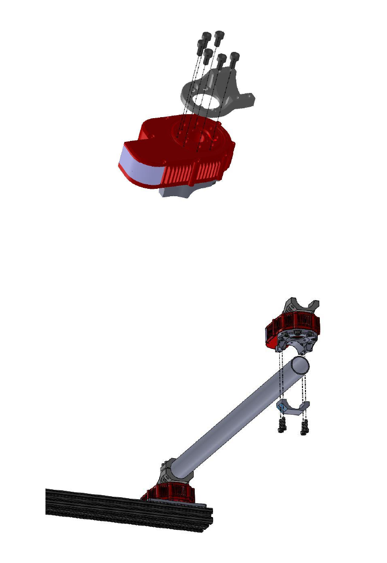
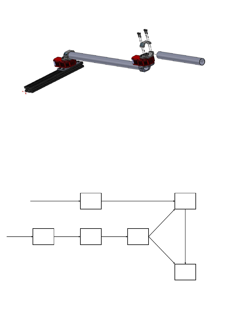
Figure 8: Attaching the Second Link to the Assembly in Fig. 7
2.2 Electrical Connections
17
E Stop
16
AC-DC
20
Splitter
21
Router
1st Hebi
Actuator
(1)
2nd Hebi
Actuator
(1)
From Ethernet Port
From Wall
Power
15
Ethernet Cable
15
Ethernet Cable
18, 19
Power Cables and
Adapters
18, 19
Power Cables and
Adapters
18, 19
Power Cables and
Adapters
Figure 9: Electrical Connections Overview
10

Figure 10: Electrical Connections on the Hebi Actuator
11
