Inter Face 5 629 05 INTERFACE C CONNECTORS
User Manual: InterFace 5 629
Open the PDF directly: View PDF ![]() .
.
Page Count: 31
Catalogue 2008
a Nexans company

1
01/2008
EUROMOLD
COMPANY PRESENTATION
While every care is taken to ensure that the information contained
in this publication is correct, no legal responsibility can be accepted
for any inaccuracy. Nexans Network Solutions N.V. - Div. Euromold
reserves the right to alter or modify the characteristics of its products
described in this catalogue as standards and technology evolve.
EUROMOLD
Euromold is the leading
European specialised designer,
manufacturer and distributor of
prefabricated cable accessories
for medium voltage energy
distribution. Euromold provides
a complete range of acces-
sories for underground cables:
pre-moulded EPDM or silicone
rubber connectors, terminations
and joints for cables and epoxy
bushings for transformers and
switch gear, as well as a large
range of cold-shrinkable
terminations and joints from 12
to 42 kV.
Euromold is also the manufac-
turer of electrical components
for the high voltage accessories
of the Nexans group.
ISO 9001 Certificate
Since 1992, Euromold’s
commitment to quality is
demonstrated by its ISO 9001
certification.
Laboratory accreditation
Since June 2000, Euromold’s
independent ELAB laboratory
obtained the BELTEST accredi-
tation no.192-T-ISO 17025
conform with the European
standards for laboratories ISO
17025 for electrical testing of
medium voltage cable acces-
sories according to the Inter-
national standards IEC 61442
and HD 629.
International standards
All our products meet the
International standards like
CENELEC HD 629.1, CENELEC
EN 50180, IEC 60137, IEEE
386 & 404… or country speci-
fications. Official certificates,
CESI, KEMA, ATEX… prove the
conformity of our products.
Long duration tests of existing
or new products are con-
tinuously performed in our test
fields.
2
01/2008
SEPARABLE CONNECTORS
AND BUSHINGS
INTERFACE C
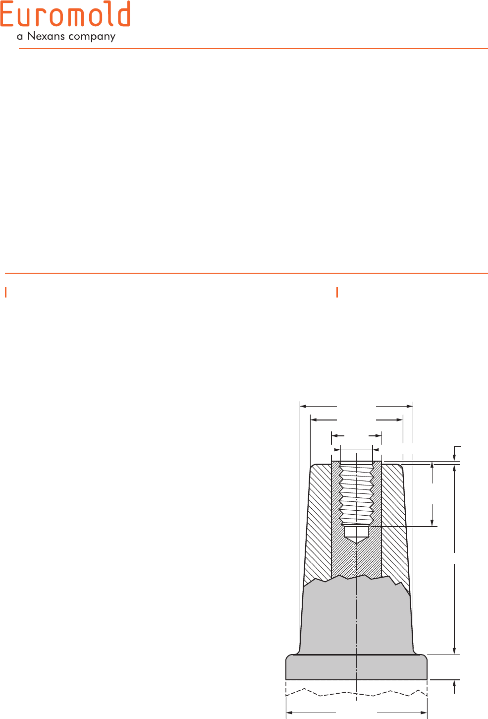
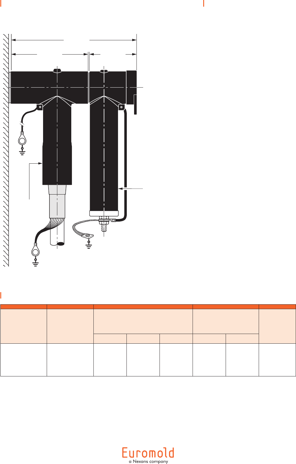
Interface C
Dimensions according to
European CENELEC EN 50180
and 50181 (in mm).
M16 x 2 - 6H
11 min.
Dia. 56± 0.2
Dia. 46± 0.2
Dia. 22
min.
1.5 0
- 0.5
29
min.
90± 0.2
Dia. 70± 0.2
Table of contents
400LB - elbow connector
430TB-630A - tee connector
400TB - tee connector
440TB - tee connector
300PB-630A - coupling connector
400AR-3 - equipment bushing
400A-24B - in-air bushing
Fixings for equipment bushings
400PB-XSA - surge arrester
300SA - surge arrester
400TR & 400TR-LB - test rod
400TK-400SW installation tools
Accessories
Possible arrangements
3
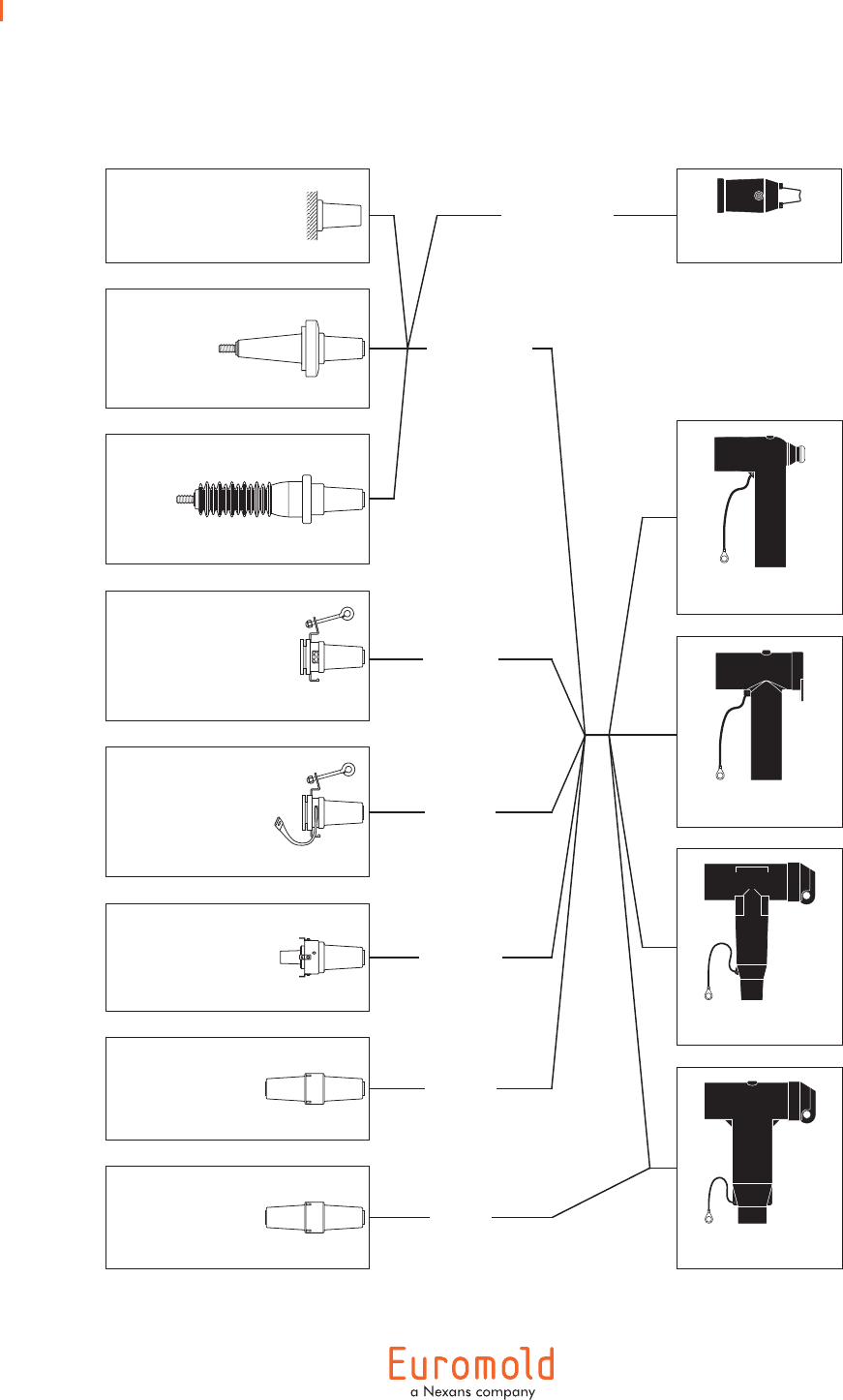
Connecting possibilities
BUSHINGS /
ACCESSORIES
CONNECTION CONNECTORS /
ACCESSORIES
cable
earthing
tap-off
630/250A
cable
isolation
one cable to
equipment
dead-ending
of equipment
(K)(M)400DR-B
Dead-end receptacle
in-line
junction
(K)430TB-630A
Tee connector
(K)400LB
Elbow connector
(K)(M)(P)400TB/G
Tee connector
(K)(M)440TB/G
Tee connector
Equipment
interface
400GP-B
Earthing plug
(K)400RTPA
Reducing tap plug
(K)(M)400SOP-B
Stand-off plug
(K)(M)440CP
Connecting plug
(K)(M)400AR-3
Equipment bushing
400A-24B
In-air bushing
(K)(M)400CP-SC
Connecting plug
in-line
junction
4
01/2008
Specifications and
standards
The separable connector 400LB
meets the requirements of
CENELEC HD 629.1.
Up to 24 kV - 630 A
Separable
connector
type
Voltage
Um
(kV)
Current
Ir
(A)
Conductor sizes (mm2)
min. max.
400LB
K400LB
12
24
630
630
25
25
300
300
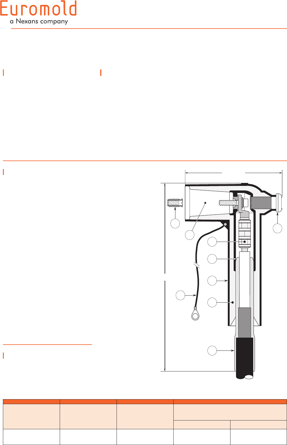
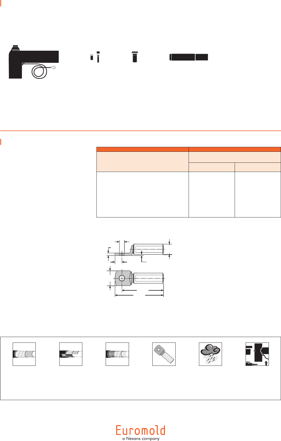
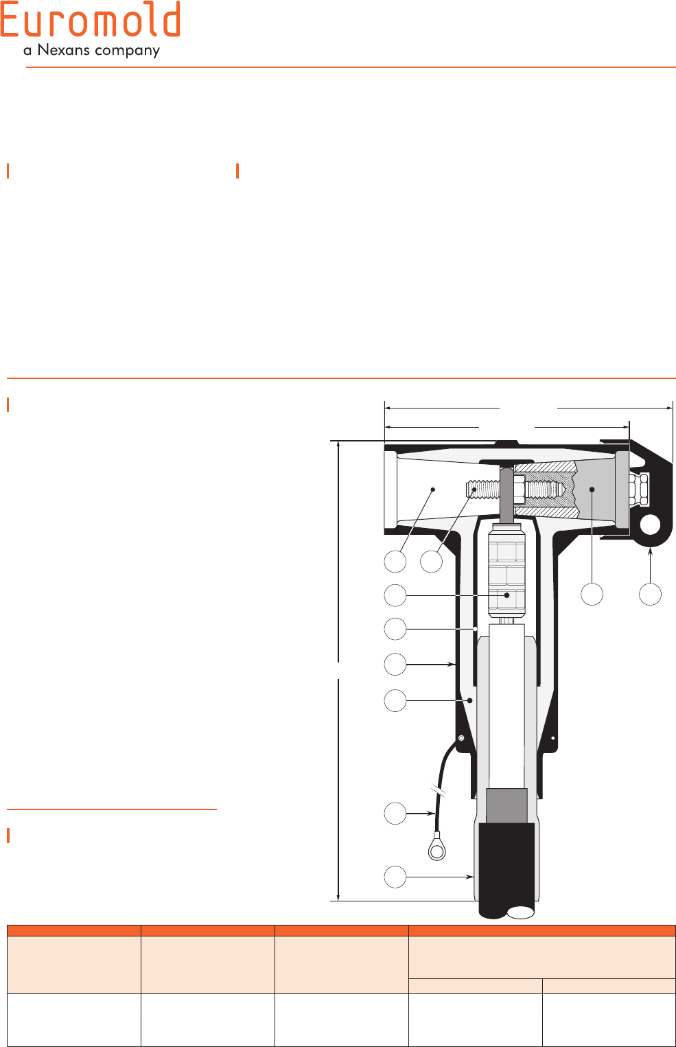
Design
Separable connector
comprising:
1. Conductive EPDM insert.
2. Conductive EPDM jacket.
3. Insulating EPDM layer
moulded between the insert
and the jacket.
4. Type C - 630 A interface
as described by CENELEC
EN 50180 and 50181.
5. Conductor connector (not
included in the standard kit).
6. Insulating plug.
7. Cable reducer.
8. Earth lead.
9. Transition contact M10/M16.
The screen break design
enables cable outer sheath
testing without removing or
dismantling the connector.
400LB
INTERFACE C
ELBOW CONNECTOR
Application
Separable elbow connector
designed to connect polymeric
insulated cable to equipment
(transformers, switch gear,
motors...).
Also connects cable to cable,
using the appropriate mating
part.
6/10 (12) kV
6.35/11 (12) kV
8.7/15 (17.5) kV
12/20 (24) kV
12.7/22 (24) kV
Technical characteristics
•ThethickconductiveEPDM
jacket provides a total safe to
touch screen which ensures
safety for personnel.
•Eachseparableconnectoris
tested for AC withstand and
partial discharge prior to
leaving the factory.
205 mm
370 mm
3
2
1
4
5
8
7
6
9
5
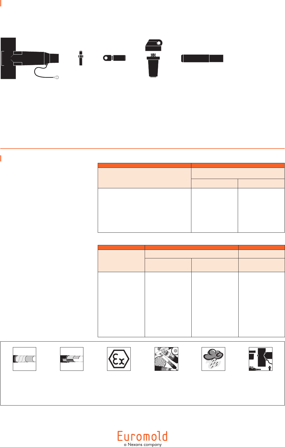
Kit contents
The complete (K)400LB elbow
connector kit comprises 3 x the
following components:
The kit also comprises lubricant, wipers,
and installation instructions.
Ordering instructions
Select the part number
which gives the best centring
to the cable core insulation
diameter.
Add a 'K' for use up to 24 kV.
Ordering
part number
Dia. over core insulation (mm)
min. max.
3 x 400LB-11
3 x 400LB-15
3 x 400LB-19
3 x 400LB-22
3 x 400LB-25
3 x 400LB-27
12.0
16.0
20.0
23.5
26.5
28.5
17.5
22.0
26.5
31.0
32.5
37.5
Example:
The copper wire screened
cables are 24 kV, 240 mm2
stranded aluminium with a
diameter over core insulation
of 32.2 mm.
Order 3 x K400LB-27 elbow
connector kit.
Can be supplied
with cable lugs.
For outdoor
applications.
Order: +MWS.
Components can be
ordered individually.
For use with
copper tape
screened cables.
Order: Kit MT.
For use with Alupe or
C 33-226 cables.
Please contact our
representative.
For use with fabric tape
(graphite) screened cables.
Order additional
semi-conductive tape
(type TSC).
+ + + = 3 x (K)400LB-W(-X)
connector kit
Table W
Notes:
We do not supply the compression
lugs in the standard kit. All types
of cable lugs can be used. The
lugs must be within the dimensions
specified and the palm of the lug
must be copper or any equivalent
alloy.
112 max.
135 max.
38
max.
Dia. 36
max.
2 max.
Dia. 10.2 or 13
10
max.
24 max.
Transition
contact +
screw assembly
400LTS
Insulating
plug
400LBP
Cable reducer
411CA-W
Connector housing
(K)400BLB
6
01/2008
Application
Separable tee shape
connector (bolted type)
designed to connect polymeric
insulated cable to equipment
(transformers, switch gear,
motors, ...).
Also connects cable to cable
when using the appropriate
mating parts.
Technical characteristics
•AthickconductiveEPDM
jacket provides a total safe to
touch screen.
•Eachseparableconnectoris
tested for AC withstand and
partial discharge prior to
leaving the factory.
Specifications and
standards
The separable connector
430TB-630A meets the
requirements of CENELEC HD
629.1.
Up to 24 kV - 630 A
Separable
connector
type
Voltage
Um
(kV)
Current
Ir
(A)
Conductor sizes (mm2)
min. max.
430TB-630A
K430TB-630A
12
24
630
630
35
35
300
300
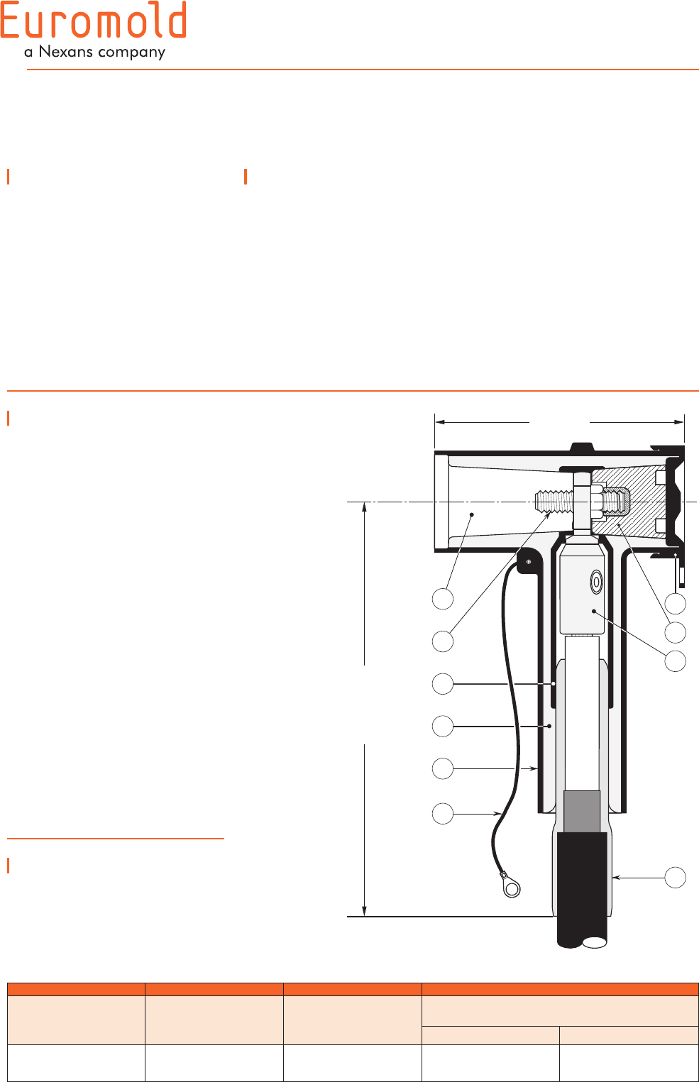
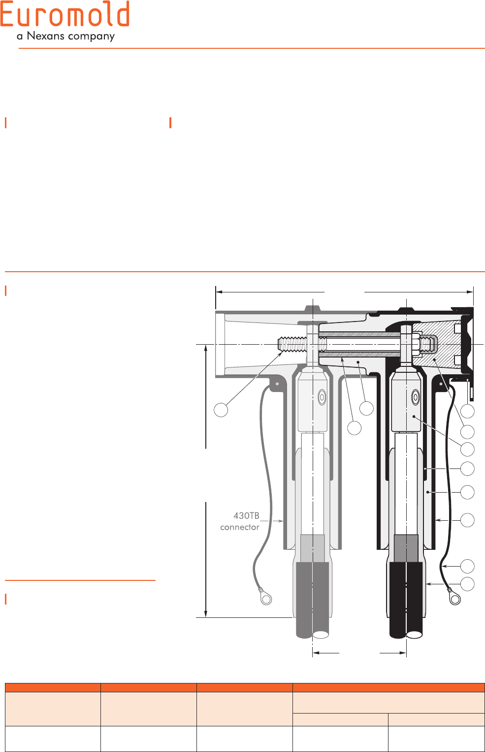
Design
1. Type C - 630 A interface
as described by CENELEC
EN 50180 and 50181.
2. Clamping screw.
3. Conductive EPDM insert.
4. Insulating EPDM layer
moulded between the
insert and the jacket.
5. Conductive EPDM jacket.
6. Conductive rubber cap.
7. Basic insulating plug
(standard version without
voltage detection point).
8. Conductor connector
9. Cable reducer.
10. Earthing lead.
The screen break design
enables cable outer sheath
testing without removing or
dismantling the connector.
430TB-630A
INTERFACE C
TEE CONNECTOR
6/10 (12) kV
6.35/11 (12) kV
8.7/15 (17.5) kV
12/20 (24) kV
12.7/22 (24) kV
183 mm
Non-size sensitive:
290 mm
Size sensitive:
350 mm
3
4
5
7
6
8
9
2
1
10
7
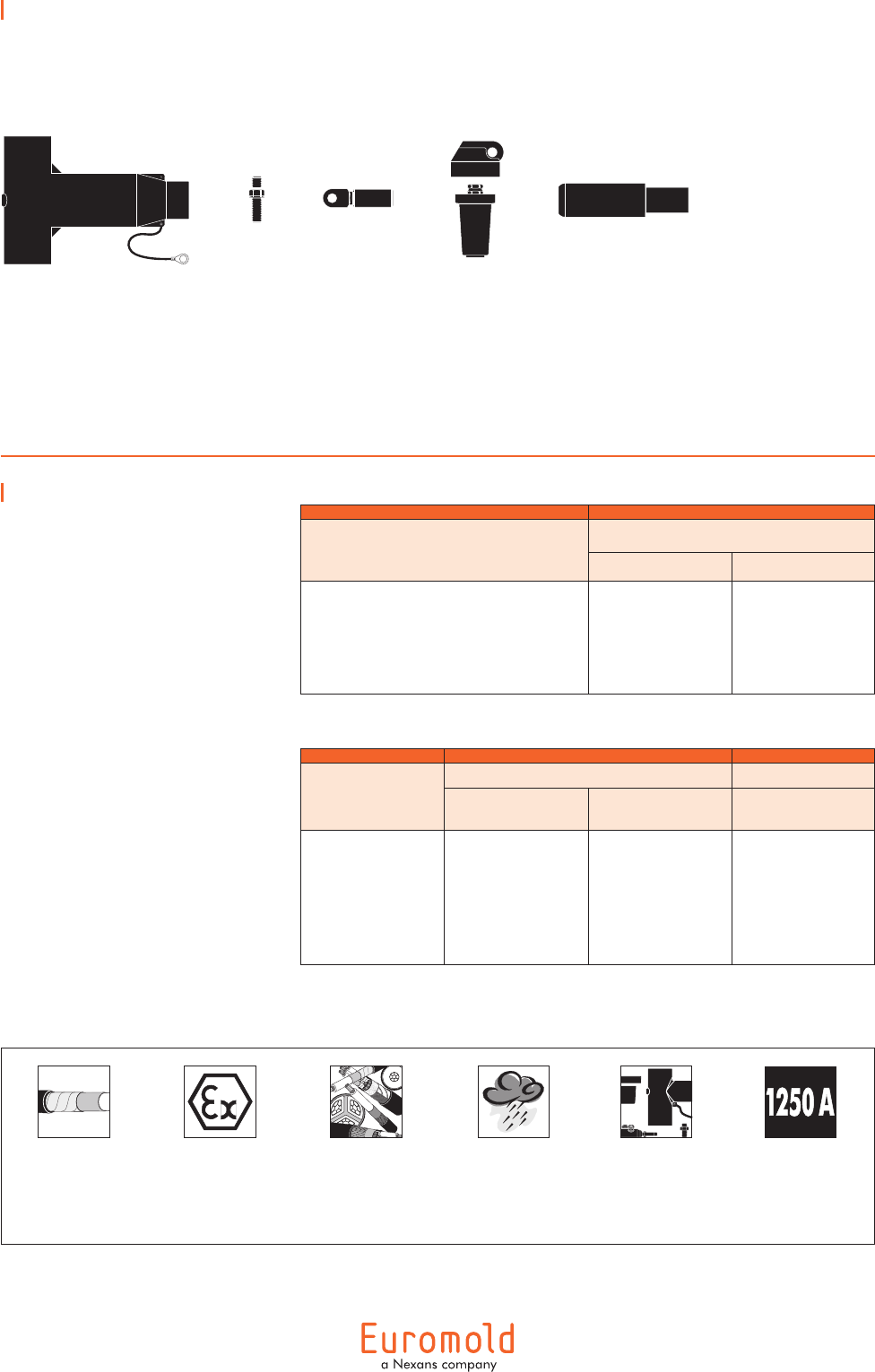
Kit contents
The complete (K)430TB-630A
tee connector kit comprises 3 x
the following components:
The kit also comprises lubricant, wipers,
water sealing mastic, installation rod,
installation instructions and crimp chart.
Ordering instructions
To order the tee connector, use
the tables beside to substitute
for W1/W2 and X in the
formulas.
Add a 'K' for use up to 24 kV.
1. From table W1 or W2:
select the symbol which
gives the best centring
of your core insulation
diameter.
2. From table X: according
to your conductor size and
type, select the designation
which completes the part
number.
Example:
The cable is 24 kV, 150 mm2
compact stranded copper with
a diameter over core insulation
of 27.5 mm.
Order 3 x
K430TB-18-95.240-14-5 for a
non-size sensitive application or
3 x K430TB -22-150(K)M-11-2
for a size sensitive application.
Clamping
screw
430TCS
Basic insu-
lating plug
+ rubber
cap 300BIPR
Connector housing
430BT-630A
Cable reducer
430CA-
W1
Cable reducer
411CA-
W2
Conductor
contact TMBC-
X
Conductor
contact TBC-
X
+ + +
+
+
=3 x (K)430TB-
W1
-
X
connector kit for
non-size sensitive
application
3 x (K)430TB-
W2
-
X
connector kit for
size sensitive
application
=
non-size
sensitive
size
sensitive
Table W
1
Table W
2
Dia. over core
insulation (mm) W2
min. max.
12.0
16.0
20.0
23.5
26.5
28.5
17.5
22.0
26.5
31.0
32.5
37.5
11
15
19
22
25
27
For use with
easy strip semi-conductive
screened cables.
Order:
Field control mastic
(type MFC).
Basic insulating plug also
available with a voltage
detection point.
Order : - /VD.
Table X
For use with
other cable types.
Please contact our
representative.
For outdoor
applications.
Order: +MWS.
For use with
copper tape
screened cables.
Order: Kit MT.
For use with Alupe or
C 33-226 cables.
Please contact our
representative.
Voltage
Um (kV) Non-size sensitive Size sensitive
12
24
3 x 430TB-W1-X
3 x K430TB-W1-X
3 x 430TB-W2-X
3 x K430TB-W2-X
Dia. over core
insulation (mm) W1
min. max.
12.0
17.0
19.0
17.5
23.5
32.6
11
16
18
Conduc-
tor sizes
(mm2)
Aluminium conductor Copper conductor
DIN
hexagonal
Deep
indent Bolted DIN
hexagonal Bolted
35
50
70
95
120
150
185
240
300
35(K)M-10-2
50(K)M-10-2
70(K)M-10-2
95(K)M-10-2
120(K)M-10-2
150(K)M-10-2
185(K)M-10-2
240(K)M-10-2
300(K)M-10-2
35KM-10-1
50(K)M-10-1
70(K)M-10-1
95(K)M-10-1
120(K)M-10-1
150(K)M-10-1
185(K)M-10-1
240(K)M-10-1
–
35(K)M-11-2
50(K)M-11-2
70(K)M-11-2
95(K)M-11-2
120(K)M-11-2
150(K)M-11-2
185(K)M-11-2
240(K)M-11-2
300(K)M-11-2
– –
8
01/2008
Up to 41.5 kV - 630 A
400TB
INTERFACE C
TEE CONNECTOR
6/10 (12) kV
6.35/11 (12) kV
8.7/15 (17.5) kV
12/20 (24) kV
12.7/22 (24) kV
18/30 (36) kV
19/33 (36) kV
20.8/36 (41.5) kV
Technical characteristics
•ThethickconductiveEPDM
jacket provides a total safe to
touch screen which ensures
safety for personnel.
•Eachseparableconnectoris
tested for AC withstand and
partial discharge prior to
leaving the factory.
Separable
connector
type
Voltage
Um
(kV)
Current
Ir
(A)
Conductor size (mm2)
min. max.
400TB/G
K400TB/G
M400TB/G
P400TB/G
12
24
36
41.5
630
630
630
630
35
35
35
35
300
300
240
240
Application
Separable tee shape
connector (bolted type)
designed to connect polymeric
insulated cable to equipment
(transformers, switch gear,
motors, ...).
Also connects cable to cable
when using the appropriate
mating parts.
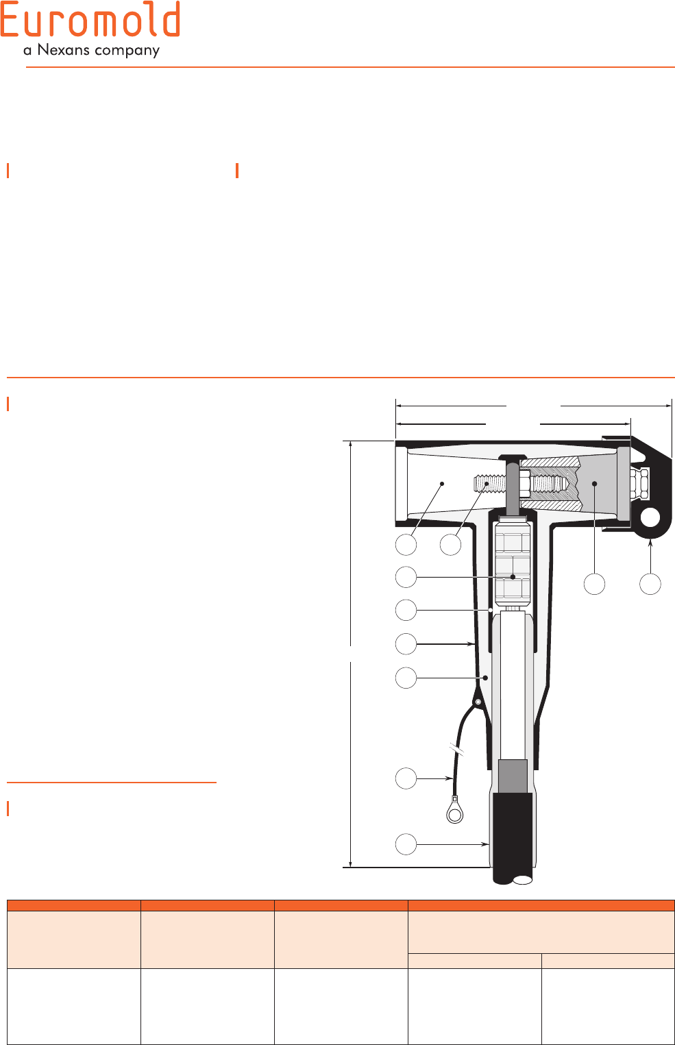
Design
Separable connector
comprising:
1. Conductive EPDM insert.
2. Conductive EPDM jacket.
3. Insulating EPDM layer.
4. Type C - 630 A interface
as described by CENELEC
EN 50180 and 50181.
5. Conductor connector.
6. Basic insulating plug (with
VD point).
7. Cable reducer.
8. Conductive rubber cap.
9. Clamping screw.
10. Earthing lead.
The screen break design
enables cable outer sheath
testing without removing or
dismantling the connector.
Specifications and
standards
The separable connector 400TB
meets the requirements of
CENELEC HD 629.1 S1.
255 mm
220 mm
390 mm
3
2
1
4
6
7
8
10
9
5
9
For use with
other cable types.
Please contact our
representative.
For outdoor
applications.
Order: +MWS.
Components can be
ordered individually.
For use with
copper tape
screened cables.
Order: Kit MT.
For use with Alupe or
C 33-226 cables.
Please contact our
representative.
For use in potentially
explosive atmospheres
(for 12 kV max.).
Order: -/ATEX.
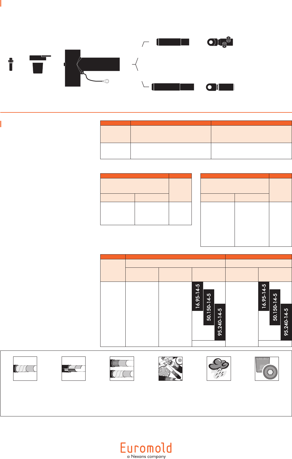
Kit contents
The complete (K)(M)(P)400TB/G
tee connector kit comprises the
following components:
The kit also comprises lubricant, wipers,
installation instructions and crimp chart.
Ordering instructions
To order the tee connector,
select the ordering part number
which gives you the best
centring of your core insula-
tion diameter and substitute X
using table X, according to your
conductor size and type.
Add a 'K' for use up to 24 kV,
an 'M' for use up to 36 kV or
add a 'P' for use up to
41.5 kV.
Ordering
part number
Dia. over core insulation (mm)
min. max.
400TB/G-11-X
400TB/G-15-X
400TB/G-19-X
400TB/G-22-X
400TB/G-25-X
400TB/G-27-X
12.0
16.0
20.0
23.5
26.5
28.5
17.5
22.0
26.5
31.0
32.5
37.5
Example:
The copper wire screened cable
is 36 kV, 150 mm2 stranded
copper with a diameter over
core insulation of 32.5 mm.
Order a M400TB/G-27-
150(K)M-11-2 tee connector kit.
Connector housing
(K)(M)(P)400BT/G
Clamping
screw
400TCS
Conductor
contact
TBC-X
Basic insulating
plug +
rubber cap
(K)(M)(P)400BIPA
Cable reducer
411CA-W
(K)(M)(P)400TB/G-W-X
connector kit
Table W
Table X
Conductor size
(mm2)
Aluminium conductor Copper conductor
DIN
hexagonal
Deep
indent
DIN
hexagonal
35
50
70
95
120
150
185
240
300
35(K)M-12-2
50(K)M-12-2
70(K)M-12-2
95(K)M-12-2
120(K)M-12-2
150(K)M-12-2
185(K)M-12-2
240(K)M-12-2
300(K)M-12-2
35KM-12-1
50KM-12-1
70KM-12-1
95KM-12-1
120KM-12-1
150KM-12-1
185KM-12-1
240KM-12-1
300KM-12-1
35(K)M-11-2
50(K)M-11-2
70(K)M-11-2
95(K)M-11-2
120(K)M-11-2
150(K)M-11-2
185(K)M-11-2
240(K)M-11-2
300(K)M-11-2
+ + + + =
10
01/2008
6/10 (12) kV
6.35/11 (12) kV
8.7/15 (17.5) kV
12/20 (24) kV
12.7/22 (24) kV
18/30 (36) kV
Up to 36 kV - 630 A
440TB
INTERFACE C
TEE CONNECTOR
Technical characteristics
•ThethickconductiveEPDM
jacket provides a total safe to
touch screen which ensures
safety for personnel.
•Eachseparableconnectoris
tested for AC withstand and
partial discharge prior to
leaving the factory.
Application
Separable tee shape
connector (bolted type)
designed to connect polymeric
insulated cable to equipment
(transformers, switch gear,
motors, ...).
Also connects cable to cable
when using the appropriate
mating parts.
Design
Separable connector
comprising:
1. Conductive EPDM insert.
2. Conductive EPDM jacket.
3. Insulating EPDM layer
moulded between the insert
and the jacket.
4. Type C - 630 A interface
as described by CENELEC
EN 50180 and 50181.
5. Conductor connector.
6. Basic insulating plug (with
VD point).
7. Cable reducer.
8. Conductive rubber cap.
9. Clamping screw.
10. Earthing lead.
The screen break design
enables cable outer sheath
testing without removing or
dismantling the connector.
Specifications and
standards
The separable connector 440TB
meets the requirements of
CENELEC HD 629.1.
Separable
connector
type
Voltage
Um
(kV)
Current
Ir
(A)
Conductor sizes (mm2)
min. max.
440TB/G
K440TB/G
M440TB/G
12
24
36
630
630
630
185
185
185
630
630
630
400 mm
3
2
1
4
7
6 8
10
9
255 mm
220 mm
5
11
Kit contents
The complete (K)(M)440TB/G
tee connector kit comprises the
following components:
The kit also comprises lubricant, wipers,
installation instructions and crimp chart.
Ordering instructions
To order the tee connector,
select the ordering part number
which gives you the best
centring of your core insula-
tion diameter and substitute X
using table X, according to your
conductor size and type.
Add a 'K' for use up to 24 kV
and add an 'M' for use up to
36 kV.
Ordering
part number
Dia. over core insulation (mm)
min. max.
440TB/G-22-X
440TB/G-27-X
440TB/G-32-X
440TB/G-37-X
440TB/G-43-X
23.5
28.5
34.0
39.0
45.5
31.0
37.5
42.5
48.5
56.0
Example:
The copper wire screened cable
is 36 kV, 240 mm2 stranded
aluminium with a diameter over
core insulation of 37.0 mm.
Order a M440TB/G-32-
240(K)M-12-2 tee connector kit.
When installed on an
appropriate equipment
bushing:
1250 A continuously
For use with
copper tape
screened cables.
Order: Kit MT.
+ + +
Connector housing
(K)(M)440BT/G
Clamping
screw
400TCS
Conductor
contact
TBC-X
Basic
insulating
plug +
rubber cap
(K)(M)400BIPA
+
Cable reducer
611CA-W
=(K)(M)440TB/G-W-X
connector kit
Table W
Table X
Conductor sizes
(mm2)
Aluminium conductor Copper conductor
DIN
hexagonal
Deep
indent
DIN
hexagonal
185
240
300
400
500
630
185(K)M-12-2
240(K)M-12-2
300(K)M-12-2
400(K)M-12-2
500(K)M-12-2
–
185KM-12-1
240KM-12-1
300KM-12-1
400KM-12-1
500KM-12-1
630KM-12-1
185(K)M-11-2
240(K)M-11-2
300(K)M-11-2
400(K)M-11-2
500(K)M-11-2
630(K)M-11-2
For use with
other cable types.
Please contact our
representative.
For outdoor
applications.
Order: +MWS.
Components can be
ordered individually.
For use in potentially
explosive atmospheres
(for 12 kV max.).
Order: -/ATEX.
12
01/2008
Application
Separable coupling connector
(bolted type) for dual cable
arrangement. It has been
designed to be used with
separable Tee connector
430TB-630A.
Total maximum current is
630 A.
Technical characteristics
•AthickconductiveEPDM
jacket provides a total safe to
touch screen.
•Eachseparableconnectoris
tested for AC withstand and
partial discharge prior to
leaving the factory.
Up to 24 kV - 630 A
300PB-630A
COUPLING CONNECTOR
FOR 430TB-630A
Separable
connector
type
Voltage
Um
(kV)
Current
Ir
(A)
Conductor sizes (mm2)
min. max.
300PB-630A
K300PB-630A
12
24
630
630
35
35
300
300
6/10 (12) kV
6.35/11 (12) kV
8.7/15 (17.5) kV
12/20 (24) kV
12.7/22 (24) kV
3
2
1
4
5
7
8
10
9
Non-size sensitive:
290 mm
Size sensitive:
350 mm
105 mm
290 mm
11
6
Specifications and
standards
The 300PB-630A coupling
connector meets the
requirements of CENELEC HD
629.1 for 10 and 20 kV levels.
Design
1. Interface designed to fit
430TB-630A connector.
2. Bus for 300PB.
3. Conductive EPDM insert.
4. Insulating EPDM layer
moulded between the
insert and the jacket.
5. Conductive EPDM jacket.
6. Conductive EPDM cap.
7. Basic insulating plug.
8. Conductor connector
(hexagonal crimping, deep
indent crimping or bolted).
9. Cable reducer.
10. Clamping screw.
11. Earth lead.
The screen break design
enables cable outer sheath
testing without removing or
dismantling the connector.
13
Kit contents
The complete (K)300PB-630A
coupling connector kit
comprises 3 x the following
components:
The kit also comprises silicone grease,
water sealing mastic, installation rod,
installation instructions and crimp chart.
Ordering instructions
To order the Tee connector, use
the tables beside to substitute
for W1/W2 and X in the
formulas.
Add a 'K' for use up to 24 kV.
1. From table W1 or W2:
select the symbol which
gives the best centring
of your core insulation
diameter.
2. From table X: according
to your conductor size and
type, select the designation
which completes the part
number.
Example:
The cable is 24 kV, 150 mm2
compact stranded copper with
a diameter over core insulation
of 27.5 mm.
Order 3 x
K300PB-18-95.240-14-5 for a
non-size sensitive application or
3 x K300PB -22-150(K)M-11-2
for a size sensitive application.
Clamping
screw
300PB-CS
Connector housing
300BPB-630A
+
For use with
copper tape
screened cables.
Order: Kit MT.
For use with
easy strip semi-conductive
screened cables. Order:
Field control mastic
(type MFC).
For use with copper
wire screened cables.
No earthing
device is
necessary.
For use with
other cable types.
Please contact our
representative.
For outdoor
applications.
Order: +MWS.
Cable reducer
430CA-
W1
Cable reducer
411CA-
W2
Conductor
contact TMBC-
X
Conductor
contact TBC-
X
+
+
+
=3 x (K)300PB-
W1
-
X
connector kit for
non-size sensitive
application
3 x (K)300PB-
W2
-
X
connector kit for
size sensitive
application
=
non-size
sensitive
size
sensitive
For use with fabric tape
(graphite) screened cables.
Order additional
semi-conductive tape
(type TSC).
Voltage
Um (kV) Non-size sensitive Size sensitive
12
24
3 x 300PB-
W1
-
X
3 x K300PB-
W1
-
X
3 x 300PB-
W2
-
X
3 x K300PB-
W2
-
X
Table W
1
Table W
2
Dia. over core
insulation (mm) W2
min. max.
12.0
16.0
20.0
23.5
26.5
28.5
17.5
22.0
26.5
31.0
32.5
37.5
11
15
19
22
25
27
Table X
Dia. over core
insulation (mm) W1
min. max.
12.0
17.0
19.0
17.5
23.5
32.6
11
16
18
Conduc-
tor sizes
(mm
2
)
Aluminium conductor Copper conductor
DIN
hexagonal
Deep
indent Bolted DIN
hexagonal Bolted
35
50
70
95
120
150
185
240
300
35(K)M-10-2
50(K)M-10-2
70(K)M-10-2
95(K)M-10-2
120(K)M-10-2
150(K)M-10-2
185(K)M-10-2
240(K)M-10-2
300(K)M-10-2
35KM-10-1
50(K)M-10-1
70(K)M-10-1
95(K)M-10-1
120(K)M-10-1
150(K)M-10-1
185(K)M-10-1
240(K)M-10-1
–
35(K)M-11-2
50(K)M-11-2
70(K)M-11-2
95(K)M-11-2
120(K)M-11-2
150(K)M-11-2
185(K)M-11-2
240(K)M-11-2
300(K)M-11-2
– –
14
01/2008
Up to 36 kV - 630 A
Equipment
bushing
type
Voltage
Ur
(kV)
Current
Ir
(A)
400AR-3
K400AR-3
M400AR-3
12
24
36
630
630
630
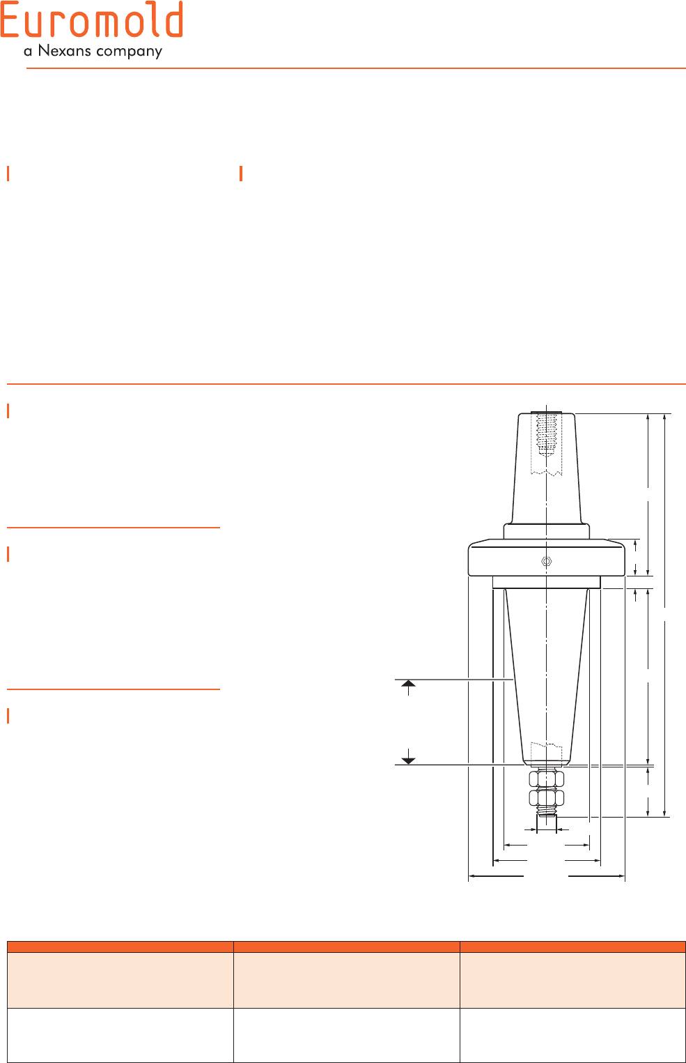
400AR-3
INTERFACE C
EQUIPMENT BUSHING
Application
For use in equipment insulated
with oil fluid, typically for
transformers, switch gear,
capacitors...
6/10 (12) kV
6.35/11 (12) kV
8.7/15 (17.5) kV
12/20 (24) kV
12.7/22 (24) kV
18/30 (36) kV
Design
The equipment bushing is a
moulded epoxy insulated part in
accordance with CENELEC EN
50180.
Technical characteristics
Each bushing is tested for
AC withstand and partial
discharge prior to leaving
the factory.
Specifications and
standards
The bolted type equipment
bushings 400AR-3 meet the
requirements of CENELEC EN
50180 and IEC 60137.
Ordering instructions
To order the equipment
bushing, specify the type.
The bushings are supplied
with an earth lead (/J) or an
earth plate (/GS). This earth
connection must be specified
when ordering.
E.g. M400AR-3/GS.
For use in potentially explosive
atmospheres (for 12 kV max.).
Order: -/ATEX.
40
Dia. 128
Dia. 88
Dia. 70
M16
133
30
10
144
330
Minimum oil level:
-12 kV: 40 mm
-24 kV: 50 mm
-36 kV: 70 mm
In mm.
15
01/2008
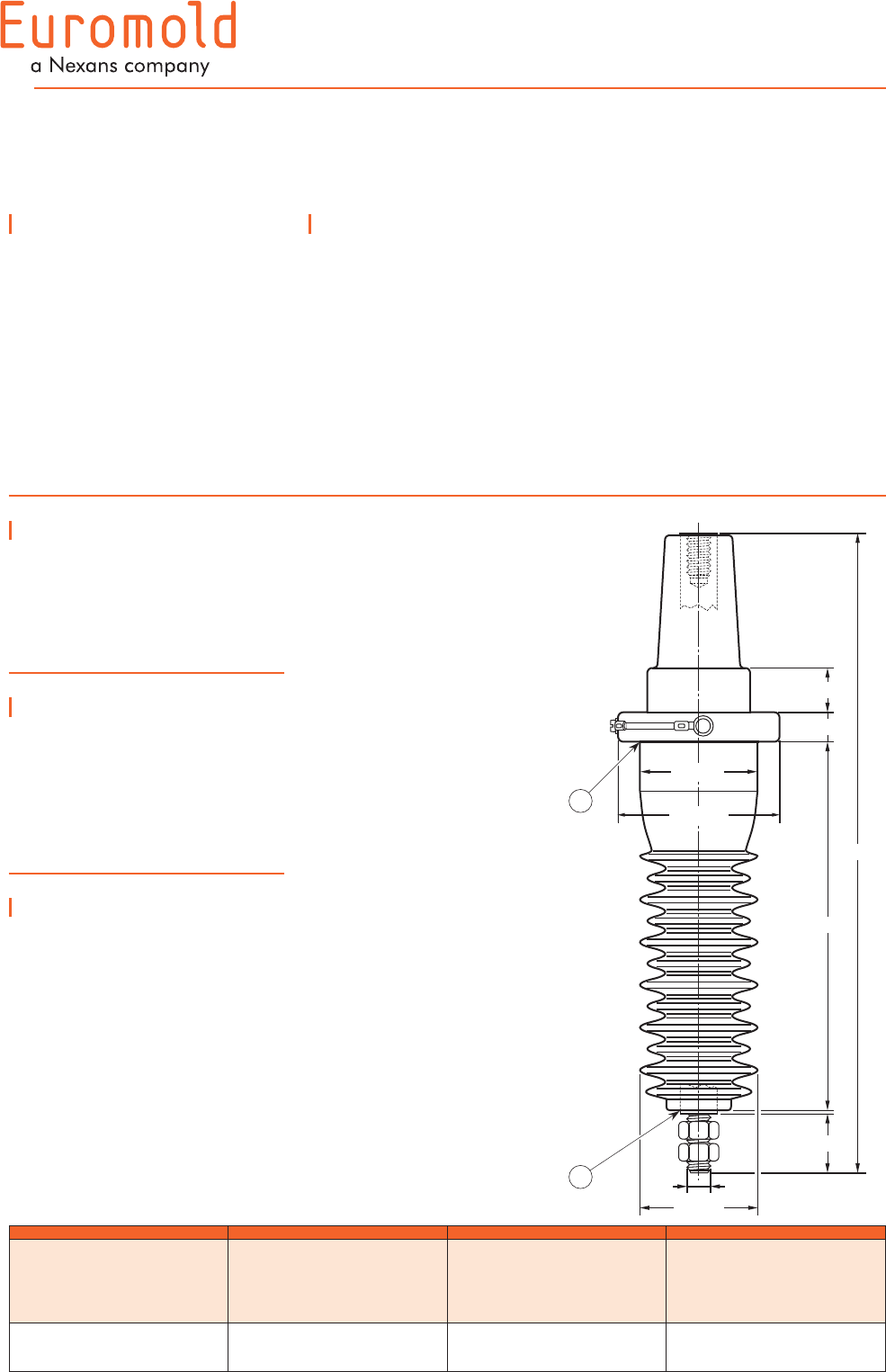
400A-24B
INTERFACE C
IN-AIR BUSHING
Specifications and
standards
The bolted type equipment
bushings 400A-24B meet the
requirements of CENELEC EN
50180 and IEC 60137.
Up to 24 kV - 630 A
Application
For use in equipment
insulated with air, typically
for transformers, switch gear,
capacitors...
Ordering instructions
To order the equipment
bushing, specify the type.
The bushings are supplied with
an earth lead.
To include the ring clamp, add:
•/B,ifperBritishstandards.
•/D,ifperGermanstandards.
•/F,ifperFrenchstandards.
E.g. 400A-24B/D.
For use in potentially explosive
atmospheres (for 12 kV max.).
Order: -/ATEX.
Technical characteristics
Each bushing is tested for
AC withstand and partial
discharge prior to leaving
the factory.
Design
The equipment bushing is a
moulded epoxy insulated part in
accordance with CENELEC EN
50181.
6/10 (12) kV
6.35/11 (12) kV
8.7/15 (17.5) kV
12/20 (24) kV
12.7/22 (24) kV
Equipment
bushing
type
Voltage
Ur
(kV)
Current
Ir
(A)
Creepage distance
A-B
(mm)
400A-24B
400A-24B
12
24
630
630
500
500
In mm.
Dia. 80
20
434
250
30
40
M16
Dia. 80
Dia. 110
A
B
16
01/2008
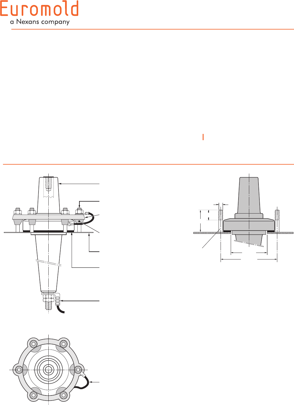
FIXINGS FOR
EQUIPMENT BUSHINGS
INTERFACE C
400AR-3/J bushing
DIN 42 538
German standards.
fixing studs
bushing interface
sealing gasket
equipment
connection
fixing flange
B DIN 42 538
E DIN 42 538
clamp
equipment
earth jumper
55
M10
Dia. 140
Dia. 90
25
6 fixing
studs
In mm
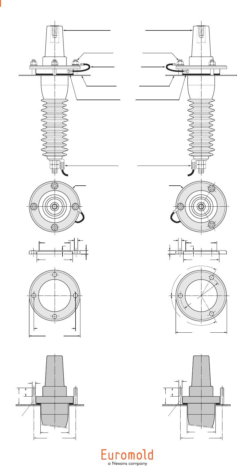
17
400A-24B In-air bushing
F
fixing flange
BCA-F
10
Dia.12
Dia. 150
126
F
120°
120°
Type BCA-F : NFC 52-053 French standards
4Dia. 94.5
Dia. 111
equipment
connection
bushing interface
fixing studs and
nuts M10
earth jumper
equipment
gasket
fixing flange
BCA-B or
BCA-D
BS 2562 stand.: 120
DIN 42 538 stand.: 123
Dia. 94.5
Dia. 111
10
Dia.12
Type BCA-B : BS 2562 British standards
Type BCA-D : DIN 42 538 German standards
4
Dia. 150
M10
Dia. 123
Dia. 82
55
25
Dia. 126
52
27
M8 or
M10
4 fixing
studs
3 fixing
studs
Dia. 82
In mm
18
01/2008
Application
Surge arrester designed
to protect medium voltage
components, including
transformers, equipment, cable
and accessories from high
voltage surges resulting from
lightning or switching.
Up to 36 kV
400PB-XSA
INTERFACE C
SURGE ARRESTER
6/10 (12) kV
6.35/11 (12) kV
8.7/15 (17.5) kV
12/20 (24) kV
12.7/22 (24) kV
18/30 (36) kV
Technical characteristics
•Thissurgearresterisametal
oxide varistor surge arrester in
an elbow configuration.
•Eacharresteristestedfor
AC withstand and partial
discharge prior to leaving the
factory.
Surge
arrester
type
Nominal
discharge
current
In (kA)
Rated
voltage
Ur
(kV)
Max. continuous
operating
voltage
Uc (kV)
Steep current
residual
voltage @ 5 kA
[1/20 µs] (kV)
Lightning current
residual
voltage @ 5 kA
[8/20 µs] (kV)
High current
impulse
withstand
(kA)
Dimensions
(mm)
L1 L2
400PB-5SA-15L
400PB-5SA-18L
400PB-5SA-22L
400PB-5SA-24L
400PB-5SA-30L
400PB-10SA-15N
400PB-10SA-18N
400PB-10SA-22N
400PB-10SA-24N
400PB-10SA-30N
400PB-10SA-36N
400PB-10SA-45N
5
5
5
5
5
10
10
10
10
10
10
10
15
18
22
24
30
15
18
22
24
30
36
45
12.0
14.4
17.6
19.2
24.0
12.0
14.0
17.6
19.2
24.0
28.8
36.0
42.4
52.7
65.7
70.0
87.3
46.2
56.0
68.9
74.4
92.7
111.1
138.2
40.0
48.0
59.0
64.0
80.0
40.2
48.6
59.8
64.5
80.4
96.4
120.0
65
65
65
65
65
100
100
100
100
100
100
100
250
250
350
350
350
250
250
350
350
350
350
450
290
290
390
390
390
290
290
390
390
390
390
490
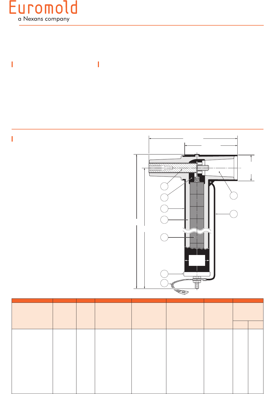
Design
Surge arrester comprising:
1. Conductive EPDM insert.
2. Conductive EPDM jacket.
3. Insulating EPDM layer
moulded between the insert
and the jacket.
4. Contact rod.
5. Earth lead.
6. Earth connection.
7. Steel cap.
8. Metal oxide valve elements.
9. Type C - 630 A interface
as described by CENELEC
EN 50180 and 50181.
6
9
5
4
3
2
1
252 mm
L2
L1
150 mm
Dia.
80 mm
7
Dia.
70 mm
8
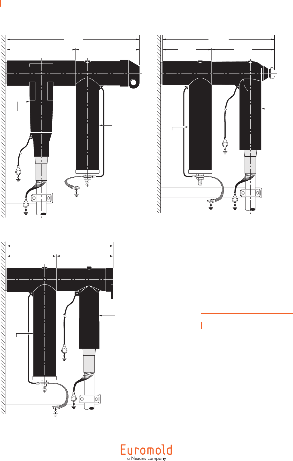
19
Typical applications and
dimensions
Ordering instructions
To order the surge arrester,
specify the surge arrester type,
as described on previous page.
Example:
For a maximum continuous
operating voltage (rms) of
24 kV and a nominal discharge
current of 10 kA.
Order a 400PB-10SA-24N
surge arrester.
410 mm
220 mm 185 mm
Type 400PB-5SA
or 400PB-10SA
surge arrester
Type
400TB/G
or
K400TB/G
tee connector
355 mm
150 mm 202 mm
Type 400LB
or K400LB
elbow connector
Type
400PB-5SA
or
400PB-10SA
surge
arrester
335 mm
150 mm 183 mm
Type 430TB
or K430TB
tee connector
Type
400PB-5SA
or
400PB-10SA
surge
arrester
20
01/2008
Application
Surge arrester designed to
protect 12 and 24 kV class
components, including
transformers, equipment, cable
and accessories from high
voltage surges resulting from
lightning or switching.
It has been designed to be
used with the separable tee
connector 430TB-630A.
Up to 24 kV
300SA
SURGE ARRESTER
FOR 430TB-630A CONNECTOR
Technical characteristics
•Thissurgearresterisametal
oxide varistor surge arrester in
an elbow configuration.
•EacharresteristestedforAC
withstand, partial discharge
and critical voltage prior to
leaving the factory.
Surge
arrester
type
Nominal
discharge
current
In (kA)
Rated
voltage
Ur (kV)
Max. continuous
operating
voltage
Uc (kV)
Dimensions
(mm)
L1 L2
300SA-10-15N
300SA-10-18N
300SA-10-22N
300SA-10-24N
300SA-10-30N
10
10
10
10
10
15
18
22
24
30
12.0
14.4
17.6
19.2
24.0
260
260
350
350
350
300
300
390
390
390
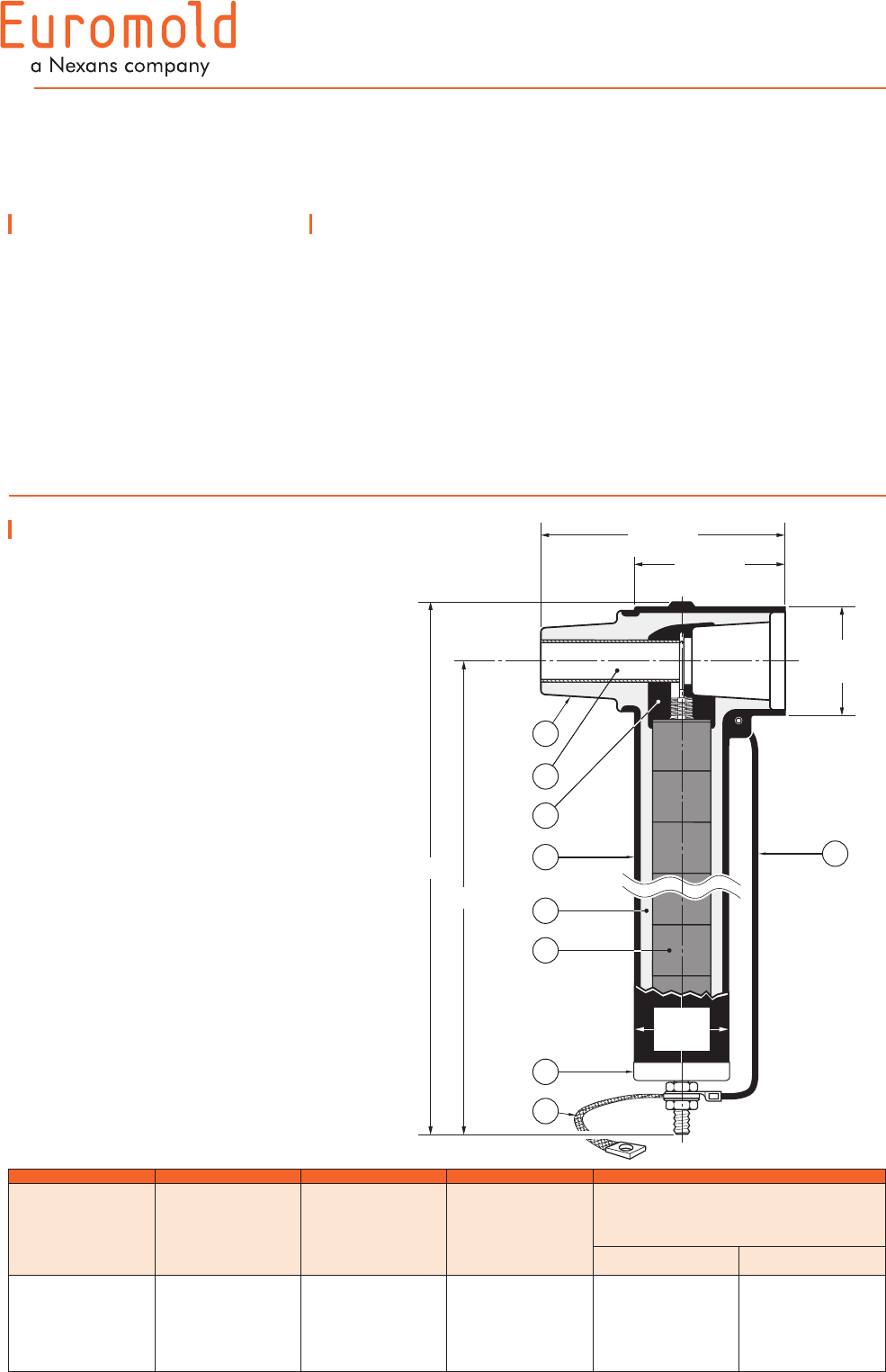
Design
Surge arrester comprising:
1. Interface designed to fit the
tee connector 430TB-630A.
2. Conductive EPDM insert.
3. Conductive EPDM jacket.
4. Insulating EPDM layer
moulded between the insert
and the jacket.
5. Receptacle for contact rod.
6. Metal oxide valve elements.
7. Steel cap.
8. Earth connection.
9. Earth lead.
8
9
5
3
4
7
6
Dia.
65 mm
2
1
170 mm
105 mm
Dia.
75 mm
L2
L1
6/10 (12) kV
6.35/11 (12) kV
8.7/15 (17.5) kV
12/20 (24) kV
12.7/22 (24) kV
21
Typical application and
dimensions
Ordering instructions
To order the surge arrester,
specify the surge arrester type,
as described on previous page.
Example:
For a maximum continuous
operating voltage (rms) of
24 kV and a nominal discharge
current of 10 kA.
Order a 300SA-10-30N surge
arrester.
290 mm
180 mm 107 mm
Type 430TB
or K430TB
tee connector
Type 300SA
surge arrester
Surge
arrester
type
Steep current
residual
voltage @ 10 kA
[1/20 µs] (kV)
Lightning current
residual voltage
[8/20 µs] (kV)
Switching impulse
residual voltage
[36/90 µs] (kV)
High current
impulse
withstand
(kA)
@ 5 kA @ 10 kA @ 20 kA @ 125 A @ 500 A
300SA-10-15N
300SA-10-18N
300SA-10-22N
300SA-10-24N
300SA-10-30N
49.6
59.6
69.5
79.4
99.3
40.8
49.0
57.1
65.3
81.6
44.5
53.4
62.3
71.2
89.0
49.8
59.8
69.7
79.7
99.6
32.4
38.8
45.3
51.8
64.7
34.2
41.0
47.9
54.7
68.4
100
100
100
100
100
Technical data
22
01/2008
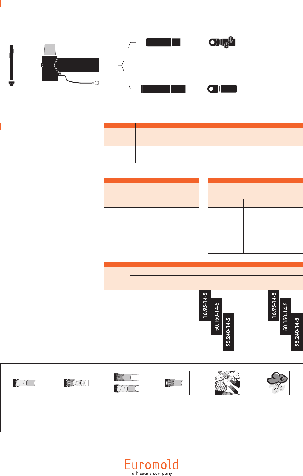
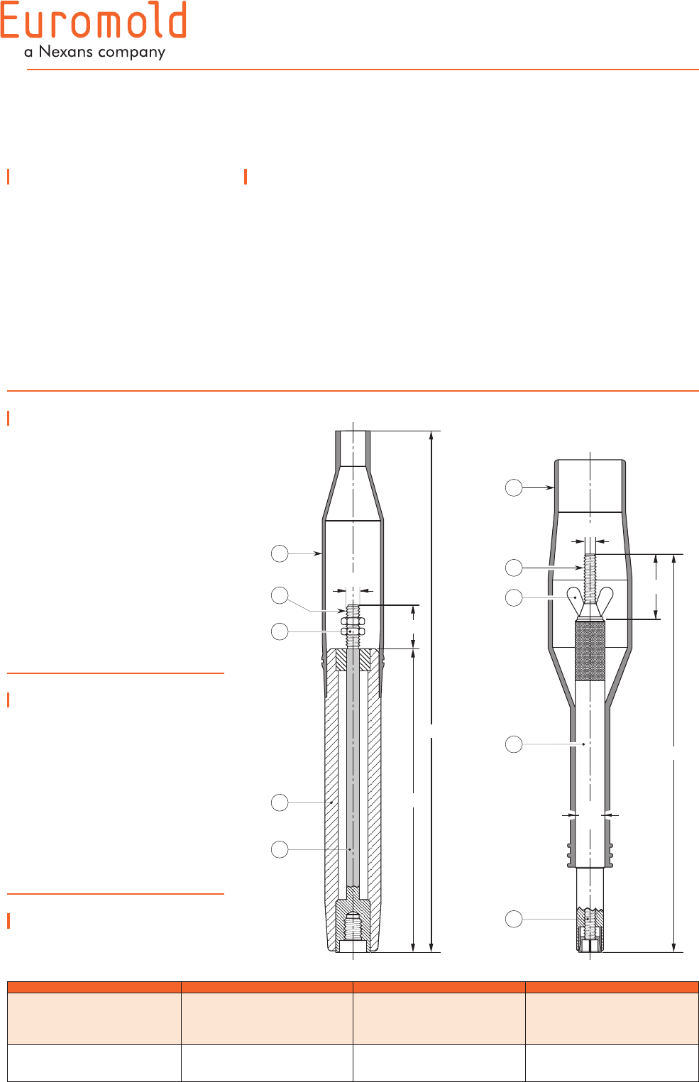
400TR and 400TR-LB
INTERFACE C
TEST RODS
Application
•Thetestrodcanbeusedfor:
- cable fault location
- cable testing
- phasing checks, etc.
•Connectionsmaybemade
with a cable lug, a 4 mm
plug or spring clips.
Installation
The test rod is mounted on
to the clamping screw in
the type C interface tee and
coupling connectors. The
test cable is connected to
the threaded stem and the
insulating shroud moved to its
final position over the end of
the test rod.
Design
1. Insulating shroud.
2. Threaded rod for test
connection.
3. Two nuts M12.
4. Insulation.
5. Copper test rod stem.
6. Wing nut.
An insulating shroud is
provided to allow the
application of test voltages
when bushings are closely
spaced.
Test rod
type
Maximum A.C.
test voltage
(50 Hz - 1 min.)
Maximum D.C.
test voltage
(8 x U0 - 30 min.)
Impulse voltage
(1.2 x 50 µs)
min.
400TR
400TR-LB
36 kV
36 kV
96 kV
96 kV
95 kV
95 kV
Technical characteristics
•The400TRtestrodcan
be used with 400TE,
430TB, 400TB and 440TB
connectors.
•The400TR-LBisforusewith
the 400LB connector.
480
4
5
2
288
40
1
3
M12
In mm.
400TR 400TR-LB
370
60
1
5
6
2
Dia.
25
M10
4
Ordering instructions
Simply specify:
400TR or 400TR-LB test rod.
23
01/2008
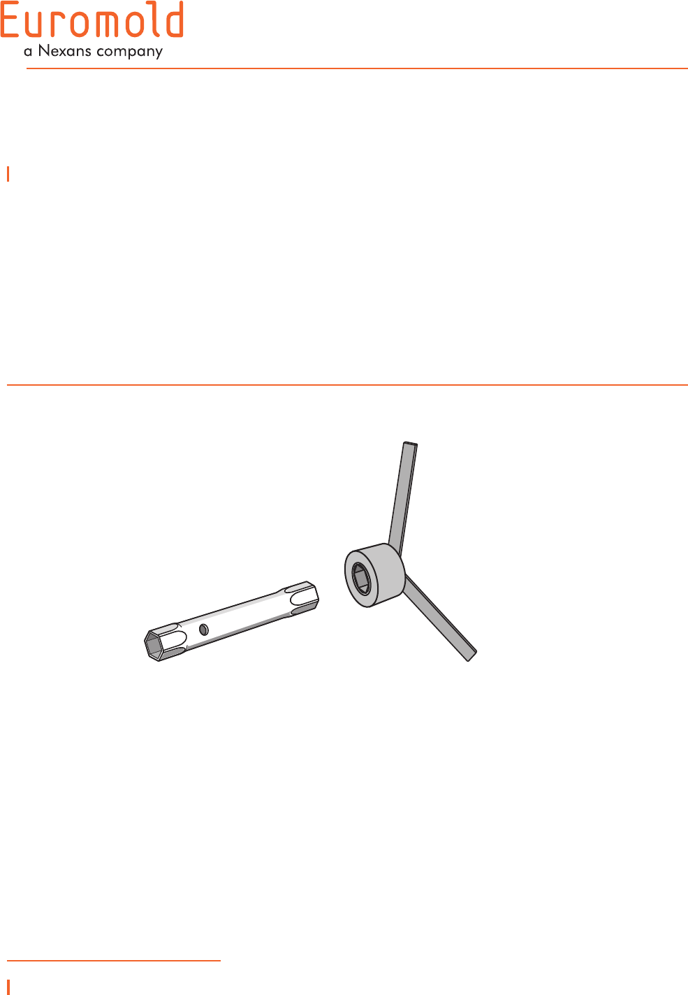
400TK & 400SW
INSTALLATION TOOL
Application
•Theboxspannerandbox
spanner key are designed
to facilitate assembly of
400TE, 400TB and 440TB
connectors.
•The400TKboxspanneris
used to install the 400TEF
clamping pin contact or
400TCS clamping screw.
Ordering instructions
Simply specify:
- 400TK box spanner
- 400SW box spanner key
•The400SWboxspanner
key fits on the hex nut of the
400BIPA basic insulating
plug.
400TK
400SW
24
01/2008
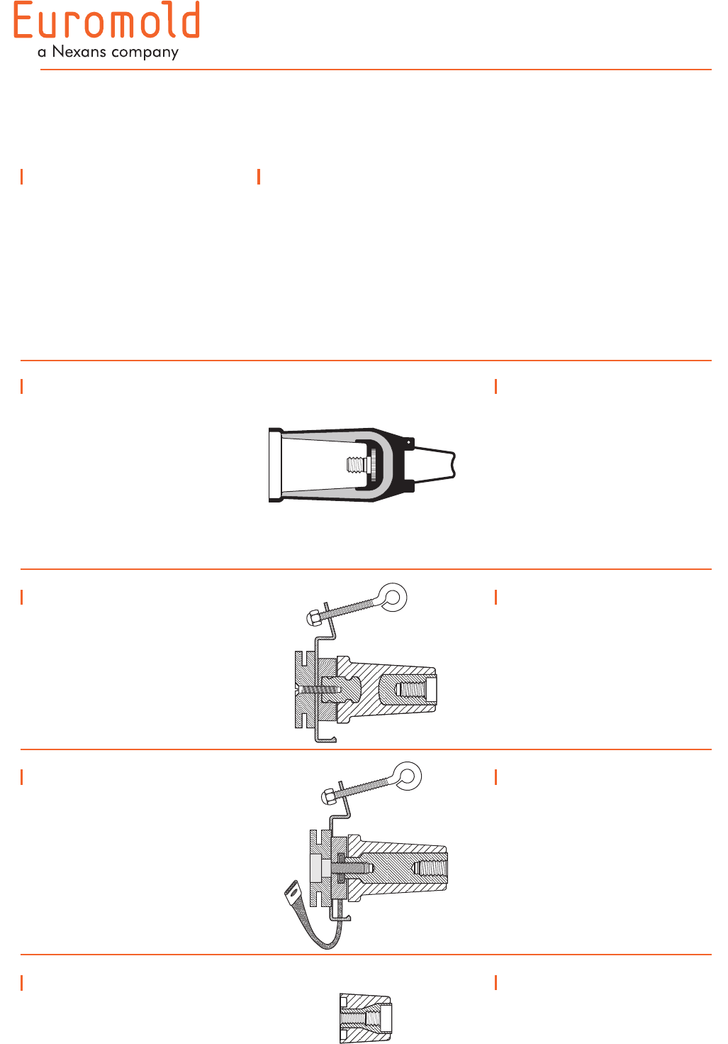
ACCESSORIES
INTERFACE C
Up to 36 kV
Application
For use with connectors and
bushings with an interface C
as described by CENELEC EN
50180 and 50181.
Technical characteristics
All these products, except the
earthing plugs, are tested for
AC withstand and partial
discharge prior to leaving
the factory.
6/10 (12) kV
6.35/11 (12) kV
8.7/15 (17.5) kV
12/20 (24) kV
12.7/22 (24) kV
18/30 (36) kV
400SOP-B
Stand-off plug
Is designed to support and
'dead-end' connectors with a
type C interface when removed
from equipment.
Ordering instructions
Order
400SOP-B for 12 kV,
K400SOP-B for 24 kV or
M400SOP-B for 36 kV
applications.
400GP-B
Earthing plug
Is designed to support and
earth connectors with a type C
interface when removed from
equipment.
Ordering instructions
Order
400GP-B for 12, 24 or 36 kV
applications.
300GP-B
Earthing plug
Is designed to earth the 430TB-
630A connectors when it is
fixed-mounted to the equipment
(maintenance earthing).
Ordering instructions
Order
300GP-B for 12 or 24 kV
applications.
400DR-B
Dead-end receptacle
Fits over a bushing with a type
C interface to provide 'dead-
end' facility.
Ordering instructions
Order
400DR-B for 12 kV,
K400DR-B for 24 kV or
M400DR-B for 36 kV
applications.
The dead-end receptacle can
be supplied with an earth lead.
Order: -/G.
E.g. K400DR-B/G.
25
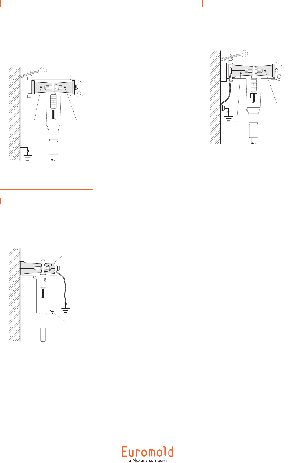
Kit MT
Earthing kit for copper
tape screened cables
Contains a tinned copper braid
(25 mm² - L = 500 mm), a
tinned copper wire for cleating
and some water sealing mastic.
Ordering instructions
Order
Kit MT for 12 kV, 24 kV
36 kV or 41.5 kV applications.
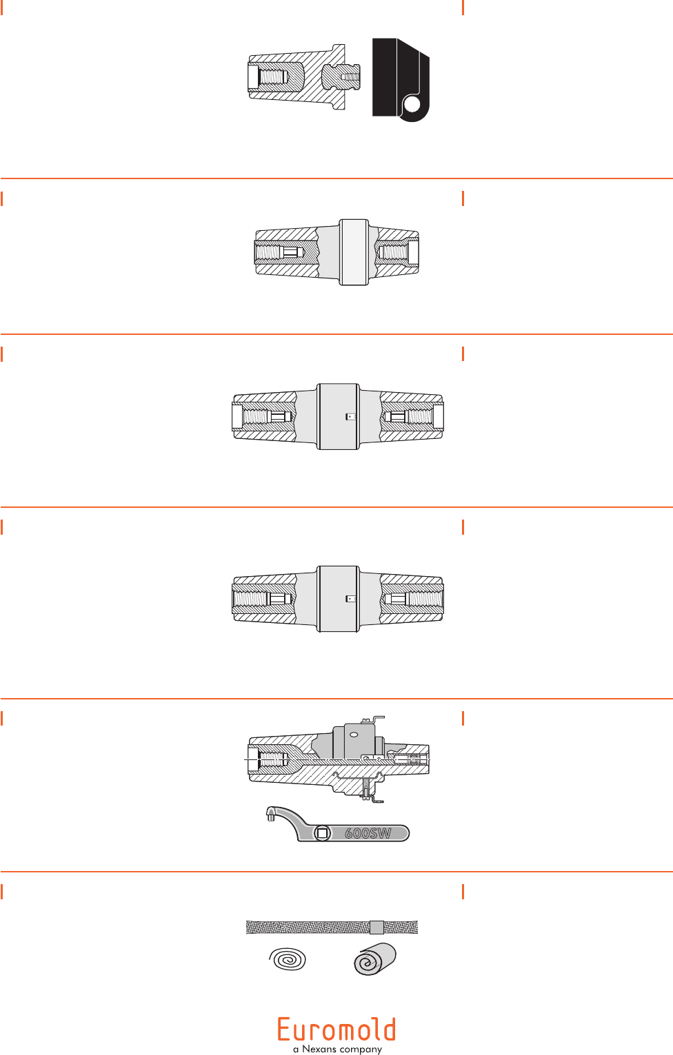
400RTPA
Reducing tap plug
Provides a type A interface
to connectors with a type C
interface.
A 'C' spanner, 600SW, is used
to tighten the reducing tap plug
on to its mating part.
Ordering instructions
Order
400RTPA for 12 kV or
K400RTPA for 24 applications.
Order 600SW for the 'C'
spanner.
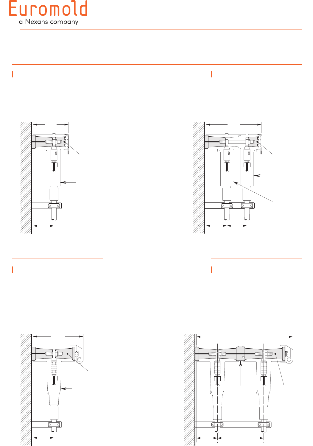
400CP-SC
Connecting plug
For connecting two or more
connectors with a type C
interface together, thus creating
a separable cable joint or a
multiple cable connection to
equipment.
Ordering instructions
Order
400CP-SC for 12 kV,
K400CP-SC for 24 kV or
M400CP-SC for 36 kV
applications.
400BIPA
Basic insulating plug
Acts as a tightening nut for
the 400TB and 440TB tee
connector kits.
The plug contains a voltage
detection point.
The conductive rubber
protection cap is included.
Ordering instructions
Order
400BIPA for 12 kV,
K400BIPA for 24 kV or
M400BIPA for 36 kV
applications.
440CP
Connecting plug
For connecting two or more
440TB connectors, thus creating
a separable cable joint or a
multiple cable connection to
equipment.
For use up to 1250 A.
Only for use with 440TB.
Ordering instructions
Order
440CP for 12 kV,
K440CP for 24 kV or
M440CP for 36 kV
applications.
Order: -/ATEX for use in
potentially explosive
atmospheres (for 12 kV max.).
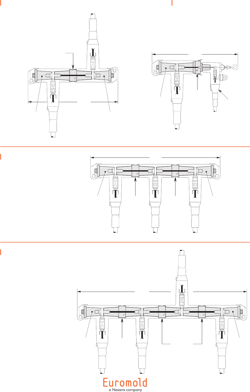
430CP
Connecting plug
For connecting two or more
430TB-630A connectors, thus
creating a separable cable joint
or a multiple cable connection
to equipment.
Ordering instructions
Order
430CP for 12 kV or
K430CP for 24 kV applications.
26
01/2008
POSSIBLE ARRANGEMENTS
INTERFACE C
430TB
Single cable arrangement.
Order 430TB for 12 kV or
K430TB for 24 kV applications.
430TB+300PB
Dual cable arrangement.
Order 430TB+300PB for 12 kV
or K430TB+K300PB for 24 kV
applications.
400TB/G
Single cable arrangement.
Order 400TB/G for 12 kV,
K400TB/G for 24 kV,
M400TB/G for 36 kV or
P400TB/G for 41.5 kV
applications.
In mm.
183
110
tee
connector
basic
insulating
plug
250
110
tee
connector
basic
insulating
plug
290
110 105
tee
connector
coupling
connector
basic
insulating
plug
400TB/G-P2
Dual cable arrangement.
Order 400TB/G-P2 for 12 kV,
K400TB/G-P2 for 24 kV or
M400TB/G-P2 for 36 kV
applications.
connecting
plug
500
110 245
basic
insulating
plug
27
In mm.
400TB/G-L4
Disconnectable tap-off.
Order 400TB/G-L4 for 12 kV,
K400TB/G-L4 for 24 kV or
M400TB/G-L4 for 36 kV
applications.
1020
basic
insulating
plug
connecting
plug
connecting
plugs
basic
insulating
plug
400TB/G-L2
2-way connection.
Order 400TB/G-L2 for 12 kV,
K400TB/G-L2 for 24 kV or
M400TB/G-L2 for 36 kV
applications.
400TB/G-L5
2-way connection with tap-off.
Order 400TB/G-L5 for 12 kV
or K400TB/G-L5 for 24 kV
applications.
connecting plug
530
basic
insulating
plug
basic
insulating
plug
505
type A
separable
connector
reducing
tap plug
basic
insulating
plug
400TB/G-L3
3-way connection.
Order 400TB/G-L3 for 12 kV,
K400TB/G-L3 for 24 kV or
M400TB/G-L3 for 36 kV
applications.
775
basic
insulating
plug
basic
insulating
plug
connecting
plug
connecting
plug
28
Connector on earthing
plug
Order 400GP-B for 12 kV,
24 kV and 36 kV applications.
earthing
plug
basic
insulating
plug
Earthing plug on
connector
Order 300GP-B for 12 kV and
24 kV applications.
430TB tee
connector
300GPB
earthing plug
Connector on stand-off
plug
Order 400SOP-B for 12 kV,
K400SOP-B for 24 kV or
M400SOP-B for 36 kV
applications.
stand-off
plug
basic
insulating
plug
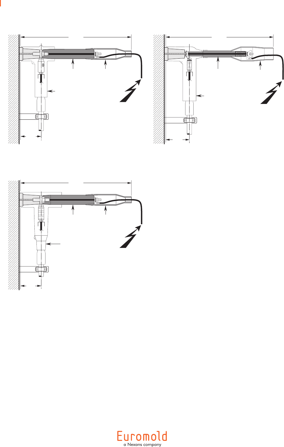
29
In mm.
110
600
insulating
shroud
400TR
test rod
400TB or 440TB
tee connector
110
430TB tee
connector
600
insulating
shroud
400TR
test rod
Cable and equipment
testing.
125
400LB elbow
connector
515
insulating
shroud
400TR-LB
test rod

Additional catalogue information on power cable accessories
is available by contacting us at the address below:
NexansNetworkSolutionsN.V.-Div.Euromold•ZuidIII,Industrielaan12,B-9320Erembodegem
Tel.:+32(0)53850211•Fax:+32(0)53831013•www.nexans.com•info.euromold@nexans.com
Catalogue also available on CD-ROM
Distributed by:
01/2008
