094 903286B_Hallicrafters_SR 150_Operating_And_Service_Instructions_May63 903286B Hallicrafters SR 150 Operating And Service Instructions May63
User Manual: 094-903286B_Hallicrafters_SR-150_Operating_And_Service_Instructions_May63
Open the PDF directly: View PDF ![]() .
.
Page Count: 33

hallicraliers
OPERATING
AND
SERVICE
INSTRUCTIONS
COMMUNICATIONS
TRANSCEIVER
MODEL SR-1SO

IMPORTANT
BEFORE
OPERATING
THE
SR-1S0
REFER
TO
PAGE
16
OF
THIS
MANUAL,
PARAGRAPH
8-3
(BIAS
ADJUSTMENT).
THE
BIAS
ADJUST-
MENT
ON
THE
POWER
SUPPLY
MUST
BE
SET
PROPERLY
TO
PRE-
VENT
PERMANENT
DAMAGE
TO
THE
FINAL
AMPLIFIER
TUBES
AND
FOR
OPTIMUM
PERFORMANCE
OF
THIS
EQUIPMENT.
"
Th
e Hallicrafter's Co
mpany
u;
arrants each ne
u;
radio product
manu-
fa
ctured
by
it to be
fr
ce. from defective mate
ri
al
and
u;
orkmans
hip
and
agrees to reme
dy
allY S
IIeI.
defect or to fllTllish a neu; pa
rt
in ex-
change for
any
part of
any
unit of its manllfacture u;hich
und
er no
r-
mal
installation, use
and
service discloses such defcct, pr
ov
id
ed the
unit
is de
li
vc
red
by
the o
u;n
er to
Oll
r autho
ri
zed radio d
ea
ler,
u;
hole-
saler,
fr
om
u;/lOm
pllrchased, or, autho
ri
ze
d service ce
nt
er,
ill
tact, for
examination, u;ith all trans/
JO
rtation charges prepa
id
u;ithin nine
ty
days from the date
of
sale to o
ri
ginal /,urchaser
and
pro
vid
ed that
such examination
di
scloses in Ollr
;udgm
e
nt
that it
is
thu
s defective.
This u;arranty does not exte
nd
to
any
of
our radio products u;hich
hav
e been sub;ec
ted
to misuse, neglect, ac
cid
ent,
in
co
rr
ect
u;
iring not
our ou;n,
improper
instal/at ion, or to use in violation
of
in
structions
furnished
by
us, nor exte
nd
ed to units u;hich ha
ve
been repaired
or
altered
outsid
e
of
our factory or authori
ze
d scr
t;
ice center, nor to cases
u;here
the
serial
numb
er thereof has been re
mo
ved, de
fa
ced or changed,
not
to accessories
used
th
ereu;ith not
of
our
own
manufa
ctur
e.
Any
part
of
a
unit
approv
ed for reme
dy
or exchange here
und
er
u;i1/
be
reme
di
ed or exc
hang
ed
by
the authorized radio dealer or
u;h
ole-
saler u;ithout charge to
the
ou;ner.
This
u;arranty is in lieu
of
all other u;arranties expressed or implied
and
no representative or person is aut/lOrized to assume for
""
allY
other
liability in connection u;ith the sale
of
our radio products:'
pliXff}
hallicraliers
CS@o

092·017851
Figure
I.
Hol/icroffers
Model
SR·
150
Transceiver.
SECTION
I
GENERAL
DESCRIPTION
The
Hallicrafters
Model
,
SR-150
Transceiver
is
a
precision-built,
compact,
high-performance
radio
equipment
of
advanced
design.
This
trans-
ceiver
utilizes
19
tubes
and
a
dual
conversion
IF
to
provide
for
the
transmission
and
reception
of
single-sideband
(SSB)
and
continuous
wave
(CW)
signals
on
the
80, 40, 20, 15,
and
10
meter
bands.
The
versatility
of
SR-150
equipment
permits
it
to
be
operated
as
a
fixed
station
or
as
a
mobile
equipment.
A
117-volt,
50/
60-cy
cle,
AC
power
supply,
complete
with
speaker
(Model
PS-150-
120),
is
available
for
fixed-station
use;
a
12-volt
DC
power
supply
,
Model
PS-150-12,
and
amobile
mounting
rack
(Model
MR-150)
are
available
when
the
transceiver
is
to
be
used
in
a
mobile
configuration.
An
advanced
feature
of
the
SR-150
equipment
is
the
Receiver
Incremental
Tuning
(RIT)
con-
trol.
This
control
enab
les
the
operator
to
unlock
the
receiver
frequency
and
tune
the
receiver
apprOXimately two
KC
either
side
of
the
trans-
mitter
frequency.
Flipping
the
RIT
switch
OFF
automatically
returns
the
equipment
to
the
trans-
ceiver
condition.
·1·
Another
special
feature
is
the
amplified
Automatic
Audio
Level
Control
(AALC)
which
functions
in
the
transmit
mode.
The
AALC
circuitry
prevents
splatter
due
to
severe
flat-topping
of
the
final
amplifier
by
providing
about
15 DB
of
compres-
sion
after
a
small
amount
of
flat-topping
occurs.
Other
features
of
the
Model
SR-150
Transceiver
include:
• A
stable,
accurately-calibrated
VFO.
• A
built-in,
100-KC
crystal
calibrator.
•
Upper
and
lower
sideband,
MaX,
(push-to-
talk),
VOX,
Manual
CW,
and
break-in
CW
operation.
• A
crystal-lattice
filter.
• A
product
detector.
• An
S-meter
/
RF
output
level
indicator.
IMPORTANT
Do
not,
under
any
circumstance,
attempt
to
operate
the
SR-150
equipment
before
becoming
completely
familiar
with
the
in-
structions
contained
within
this
manual.
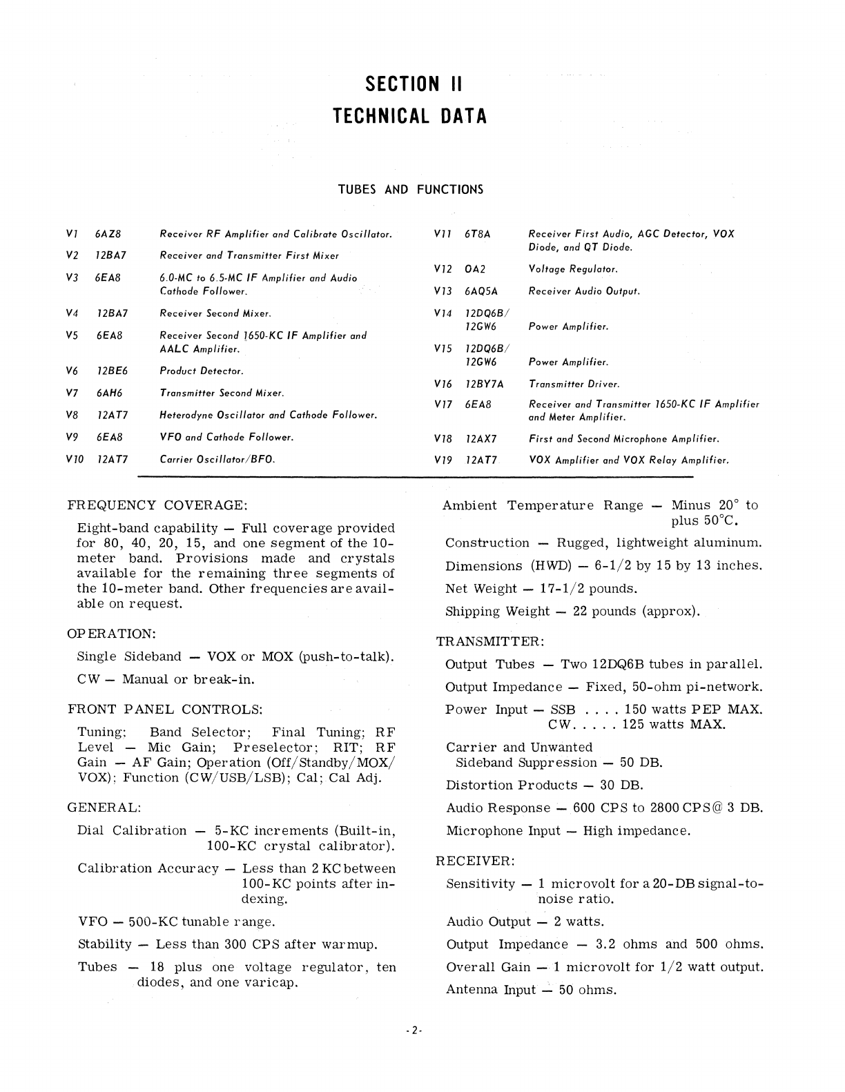
SECTION
II
TECHNICAL
DATA
TUBES
AND
FUNCTIONS
VI
6AZ8
Receiver
RF
Amplifier
and
Calibrate
Oscillator.
V2
12BA7
Receiver
and
Transmitter
First
Mixer
V3
6EA8
6.0-MC
to
6.5-MC
IF
Amplifier
and
Audio
Cathode Follower.
V4
12BA7
Receiver
Second
Mixer.
V5
6EA8
Receiver
Second
!650·KC
IF
Amplifier
and
AALC
Amplifier.
V6 12BE6
Product
Detector.
V7 6AH6
Transmitter
Second
Mixer.
V8
12AT7
Heterodyne
Oscillator
and Cathode Follower.
V9
6EA8
VFO and Cathode Follower.
Vl0
12AT7
Carrier
Oscillator/BFO.
FREQUENCY
COVERAGE:
Eight-band
capability
-
Full
coverage
provided
for
80,
40, 20,
15,
and
one
segment
of
the
10-
meter
band.
Provisions
made
and
crystals
available
for
the
remaining
three
segments
of
the
10-meter
band.
Other
frequencies
are
avail-
able
on
request.
OPERATION:
Single
Sideband
-
VOX
or
MOX
(push-to-talk).
CW -Manual
or
break-in.
FRONT
PANEL
CONTROLS:
Tuning;
Band
Selector;
Final
Tuning;
RF
Level
-Mic Gain;
Preselector;
RIT;
RF
Gain
-
AF
Gain;
Operation
(Off/Standby/MOX/
VOX);
Function
(CW/USB/LSB);
Cal;
Cal Adj.
GENERAL:
Dial
Calibration
-
5-KC
increments
(Built-in,
100-KC
crystal
calibrator).
Calibration
Accuracy
-
Less
than
2
KCbetween
100-
KC
points
after
in-
dexing.
VFO
-
500-KC
tunable
range.
stability
-
Less
than
300
CPS
after
warmup.
Tubes
-18
plus
one
voltage
regulator,
ten
diodes,
and
one
varicap.
-2-
Vl1
6T8A
Receiver
First
Audio,
AGC
Detector,
VOX
Diode, and
QT
Diode.
V12
OA2
Voltage
Regulator.
VB
6AQ5A
Receiver
Audio
Output.
V14
12DQ6B/
12GW6
Power Amplifier.
V15
12DQ6B/
12GW6
Power
Amplifier.
V16
12BY7A
Transmitter
Driver.
V17
6EA8
Receiver
and
Transmitter
1650-KC
IF
Amplifier
and
Meter
Amplifier.
V18
12AX7
First
and
Second
Microphone
Amplifier.
V19
12AT7
VOX
Amplifier
and
VOX
Relay
Amplifier.
Ambient
Temperature
Range
-
Minus
20°
to
plus
50°C.
Construction
-
Rugged,
lightweight
aluminum.
Dimensions
(HWD)
-
6-1/2
by 15
by
13
inches.
Net
Weight -
17-1/2
pounds.
Shipping Weight -
22
pounds
(approx).
TRANSMITTER:
Output
Tubes
-Two 12DQ6B
tubes
in
parallel.
Output
Impedance
-
Fixed,
50-ohm
pi-network.
Power
Input
-SSB
....
150
watts
PEP
MAX.
CWo
....
125
watts
MAX.
Carrier
and
Unwanted
Sideband
Suppression
-50 DB.
Distortion
Products
-30 DB.
Audio
Response
-600 CP S to 2800
CP
S @ 3 DB.
Microphone
Input
-High
impedance.
RECEIVER:
Sensitivity
- 1
microvolt
for
a
20-DB
signal-to-
noise
ratio.
Audio
Output
- 2
watts.
Output
Impedance
-
3.2
ohms
and
500
ohms.
Overall
Gain
-1
microvolt
for
1/2
watt
output.
Antenna
Input""::"
50
ohms.
IF
-Dual
Conversion:
First
IF
....
6.0
MC
to 6.5
MC
variable
(tunes
with
the
VFO).
Second
IF
...
1650 KC,
crystal-lattice
filter.
Heterodyning
Crystals
-
Type
CR-23/U,
third
overtone,
series
re-
sonant.
ACCESSORIES:
Mobile
Mounting
Rack
Model
MR-150
-
Quick
release
design
adaptable
to
transmission
hump
or
floor
mount
...
all
connections
made
simul-
taneously
...
access
holes
for
VOX
controls.
Net
Weight -10
pounds.
Shipping Weight -
12-3/4
pounds
(approx).
12-volt
DC
Power
Supply Model
PS-150-12
Designed
for
out-of-the-way
trunk
installation
...
terminal
strip
provides
for
quick-and-easy
connection
to
the
cable
from
the
mounting
rack
...
contains
five
silicon
diode
rectifiers
and
four
transistors.
Input
Power
Requirements:
Transmit
(CW)
....
19
amperes.
Receive
.........
14
amperes.
Dimensions
(HWD)
-
3-3/4
by10
by6-3/4
inches.
Net
Weight -
5-1/2
pounds.
Shipping Weight - 9
pounds
(approx).
117-volt
AC
Power
Supply Model
PS-150-120
-
Styled
as
a
companion
unit
to
the
Model SR-150
Transceiver,
this
supply
also
contains
a
4-inch
by
6-inch
speaker
...
one-cable
connection
carries
power
to,
and
audio
from,
the
transceiver
..
may
be
plugged
into
any
115-voltwall
outlet..
contains
five
silicon
diode
rectifiers.
Input
Power
Requirements:
Transmit
(CW)
....
290
watts.
Receiver
........
150
watts.
Dimensions
(HWD)
-
6-1/4
by7-1/2
byl0
inches.
Net
Weight -
22
pounds.
Shipping Weight -
28-1/2
pounds
(approx).
SECTION
III
INSTALLATION
WARNING
LETHAL
HIGH VOLTAGE IS
PRESENT
WITHIN THIS EQUIPMENT.
BE
CARE-
FUL
WHEN INSTALLING
THE
UNIT,
WHEN
MAKING BIAS ADJUSTMENTS,
AND WHEN
PERFORMING
CHECKS
UNDER
THE
CHASSIS.
3·1.
UNPACKING.
Carefully
remove
this
equipment
from
its
carton
and
packing
material
and
examine
it
for
any
possible
damage
which
may
have
occurred
during
transit.
Should any
sign
of
damage
be
ap-
parent,
immediately
file
a
claim
with
the
carrier
stating
the
extent
of
the
damage.
Check
all
ship-
ping
labels
and
tags
for
special
instructions
before
removing
or
destroying
them.
3·2.
LOCATION.
The
Model SR-150
Transceiver
maybeplaced
in
any
location
permitting
free
air
circulation
through
the
ventilation
openings
in
the
cabinet.
However,
excessively
warm
locations
such
as
those
adjacent
to.
radiators
and
heating
units
should
be
avoided.
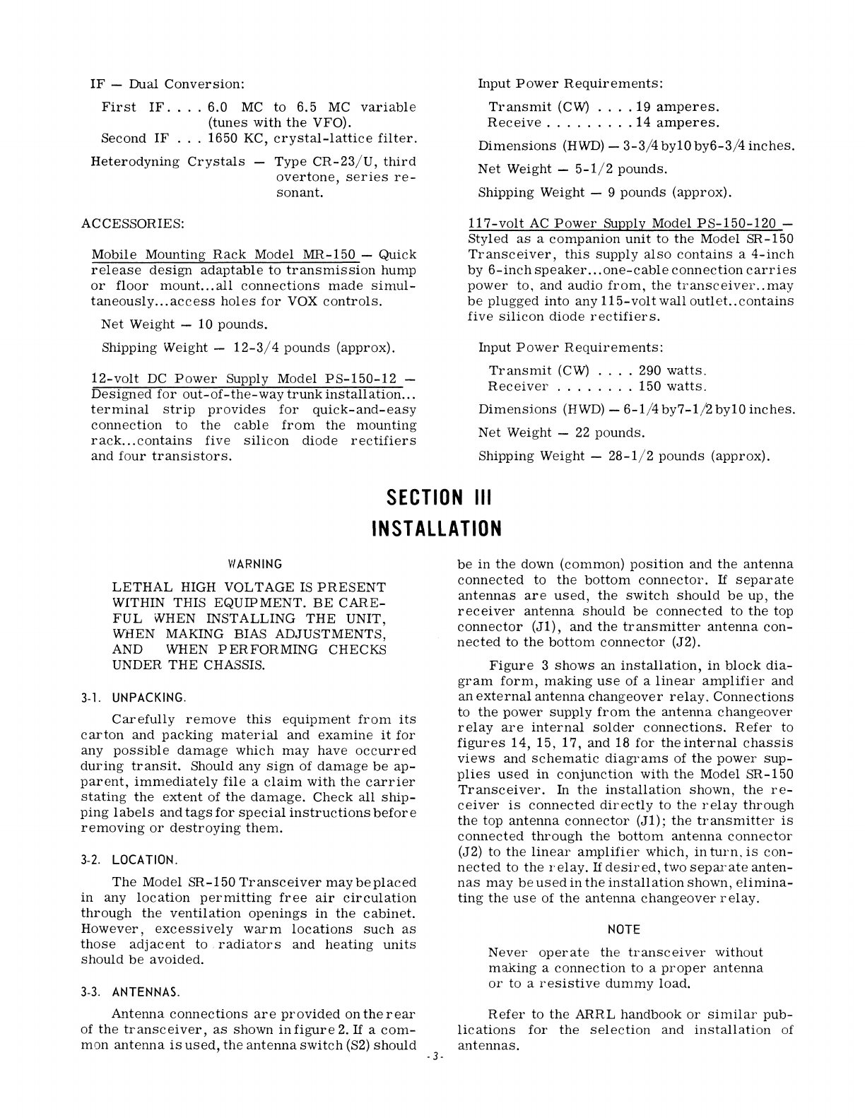
3·3.
ANTENNAS.
Antenna
connections
are
provided
on
the
rear
of
the
transceiver,
as
shown
in
figure
2.
If
a
com-
mon
antenna
is
used,
the
antenna
switch
(S2)
should
·3·
be
in
the
down (common)
position
and
the
antenna
connected
to
the
bottom
connector.
If
separate
antennas
are
used,
the
switch
should
be
up,
the
receiver
antenna
should
be
connected
to
the
top
connector
(Jl),
and
the
transmitter
antenna
con-
nected
to
the
bottom
connector
(J2).
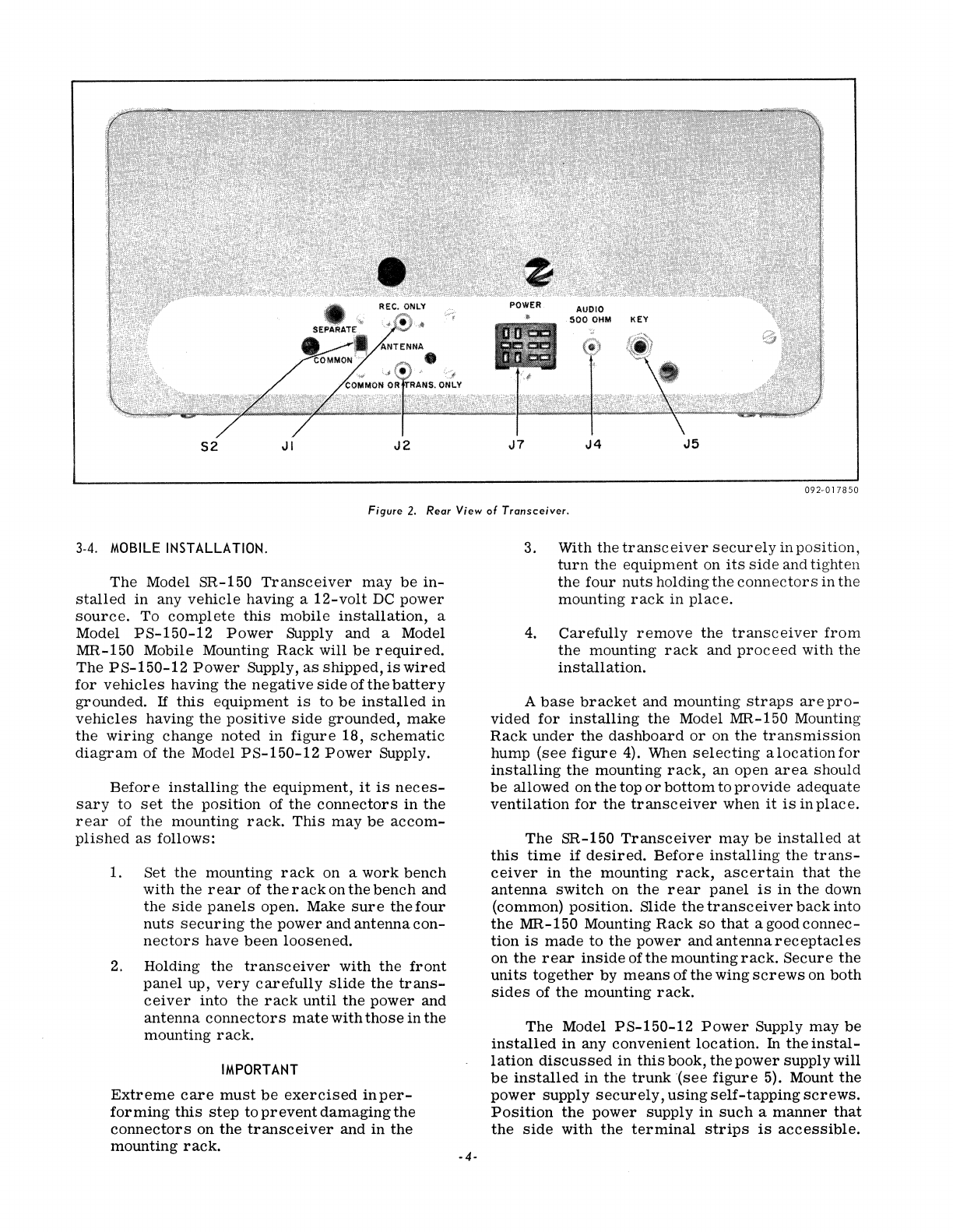
Figure
3
shows
an
installation,
in
block
dia-
gram
form,
making
use
of
a
linear
amplifier
and
an
external
antenna
changeover
relay.
Connections
to
the
power
supply
from
the
antenna
changeover
relay
are
internal
solder
connections.
Refer
to
figures
14,
15,
17,
and
18
for
the
internal
chassis
views
and
schematic
diagrams
of
the
power
sup-
plies
used
in
conjunction
with
the
Model b'R-150
Transceiver.
In
the
installation
Shown,
the
re-
ceiver
is
connected
directly
to
the
relay
through
the
top
antenna
connector
(Jl);
the
transmitter
is
connected
through
the
bottom
antenna
connector
(J2) to
the
linear
amplifier
which,
in
turn.
is
con-
nected
to
the
relay.
If
desired,
two
separate
anten-
nas
may
be
used
in
the
installation
shown,
elimina-
ting
the
use
of
the
antenna
changeover
relay.
NOTE
Never
operate
the
transceiver
without
making
a
connection
to
a
proper
antenna
or
to a
resistive
dummy
load.
Refer
to
the
ARRL handbook
or
similar
pub-
lications
for
the
selection
and
installation
of
antennas.
52
JI
J2
J7
J4
J5
092-017850
Figure
2.
Rear
View
of
Transceiver.
3-4. MOBILE INSTALLATION.
The
Model SR-150
Transceiver
may
be
in-
stalled
in
any
vehicle
having a
12-volt
DC
power
source.
To
complete
this
mobile
installation,
a
Model
PS-150-12
Power
Supply and a Model
MR-150 Mobile Mounting
Rack
will
be
required.
The
PS-150-12
Power
Supply,
as
shipped,
is
wired
for
vehicles
having
the
negative
side
ofthe
battery
grounded_
If
this
equipment
is
to
be
installed
in
vehicles
having
the
positive
side
grounded,
make
the
wiring
change
noted
in
figure
18,
schematic
diagram
of
the
Model
PS-150-12
Power
Supply.
Before
installing
the
equipment,
it
is
neces-
sary
to
set
the
position
of
the
connectors
in
the
rear
of
the
mounting
rack.
This
may
be
accom-
plished
as
follows:
1. Set
the
mounting
rack
on a
work
bench
with
the
rear
of
the
rack
on
the
bench
and
the
side
panels
open. Make
sure
the
four
nuts
securing
the
power
and
antenna
con-
nectors
have
been
loosened.
2.
Holding
the
transceiver
with
the
front
panel
up,
very
carefully
slide
the
trans-
ceiver
into
the
rack
until
the
power
and
antenna
connectors
mate
with
those
in
the
mounting
rack.
IMPORTANT
Extreme
care
must
be
exercised
inper-
forming
this
step
to
prevent
damaging
the
connectors
on
the
transceiver
and
in
the
mounting
rack.
-4-
3. With
the
transceiver
securely
in
position,
turn
the
equipment
on
its
side
and tighten
the
four
nuts
holding
the
connectors
in
the
mounting
rack
in
place.
4.
Carefully
remove
the
transceiver
from
the
mounting
rack
and
proceed
with
the
installation.
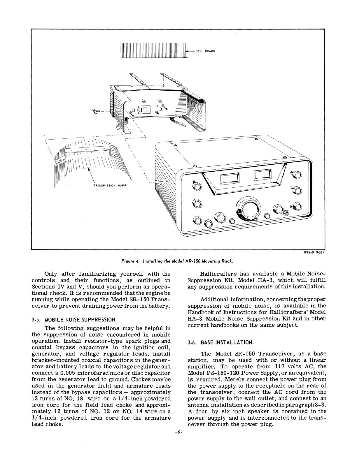
A
base
bracket
and mounting
straps
are
pro-
vided
for
installing
the
Model MR-150 Mounting
Rack
under
the
dashboard
or
on
the
transmission
hump
(see
figure
4). When
selecting
a
location
for
installing
the
mounting
rack,
an open
area
should
be
allowed on
the
top
or
bottom
to
provide
adequate
ventilation
for
the
transceiver
when
it
is
inplace.
The
SR-150
Transceiver
may
be
installed
at
this
time
if
desired.
Before
installing
the
trans-
ceiver
in
the
mounting
rack,
ascertain
that
the
antenna
switch
on
the
rear
panel
is
in
the
down
(common)
position.
Slide
the
transceiver
back
into
the
MR-150 Mounting
Rack
so
that
a good
connec-
tion
is
made
to
the
power
and
antenna
receptacles
on
the
rear
inside
of
the
mounting
rack.
Secure
the
units
together
by
means
of
the
wing
screws
on
both
sides
of
the
mounting
rack.
The
Model
PS-150-12
Power
Supply
may
be
installed
in
any
convenient
location.
In
the
instal-
lation
discussed
in
this
book,
the
power
supply will
be
installed
in
the
trunk
'(see
figure
5). Mount
the
power
supply
securely,
using
self-tapping
screws.
Position
the
power
supply
in
such
a
manner
that
the
side
with
the
terminal
strips
is
accessible.
LINEAR
AMPlIFIE.R
IN
OUT
TRANSMIT
,--
--0
\[7
EXTERNAL
ANTENNA
RELAY
SR - I
50
TRANSCEIVER
RECEIVE
b D
-0
POWER
ANTENNA
~
POWER I
SUPPLY
SWITCH
L..o
SOCKET
....
I
PS-150-120
(UP)
(MALE)
I
A I
II
!O
PIN
II
POWER
(?
PIN
10
PLUG
(FEMALE)
TO
EXTERNAL
117
V-GO
CPS
)
092·017686B
Figure
3.
Base
InstalIation, Using a Linear Amplifier.
Run
the
cable
from
the
mounting
rack
under
the
floor
mat
and
under
the
rear
seat
into
the
trunk.
Since
this
cable
is
weatherproof,
it
may
be
threaded
underneath
the
vehicle
if
desired.
Cut
the
cable
to
the
desired
length,
strip
the
wires,
and
connect
these
wires
to
the
terminal
strip
on
the
power
supply
(see
figures
5 and 17
for
color
coding
and
terminal
numbering).
IMPORTANT
Before
connecting
to
the
vehicle's
bat-
tery,
check
the
transceiver,
if
already
installed,
to
ascertain
that
the
OP
ERA-
TION
switch
is
in
the
OFF
position.
Connect
the
two
NO.
8 A
WG
wires
supplied
between
the
two-connector
terminal
strip
on
the
power
supply
and
the
battery.
The
red/white
wire
should
be
connected
from
the
top
terminal
on
the
power
supply
to
the
positive
(+)
side
of
the
battery
and
the
red/black
wire
from
the
bottom
terminal
to
the
negative
(-)
side
ofthe
battery.
These
wires
should
be
cut
to a
suitable
length
before
being
con-
nected
to
the
battery.
The
positive
lead
should
be
connected
to
the
battery
through
a
30-ampere
fuse
block
(not
supplied,
see
figure
5).
If
the
vehicle
has
a
positive
ground
electrical
system,
fuse
the
nega-
tive
lead.
CAUTION
USE CARE WHEN MAKING CONNEC-
TIONS TO THE BATTERY IN THE
VEHICLE. THE POWER
IN
ABATTERY
CAN CAUSE DANGEROUS BURNS
AND
EVEN EXPLOSION
IF
SHORT
CIRCUITED.
·5-
Connect
the
speaker
to
the
jack
provided
on
the
side
of
the
mounting
rack.
This
jack
accepts
a
standard
PL55
type plug.
Use
of
the
auto
radio
loud
speaker
is
not
recommended
unless
a
switch
is
installed
to
remove
the
speaker
from
the
auto
radio
when
operating
the
SR-150.
Install
the
antenna
in
the
manner
recom-
mended
by
the
antenna
manufacturer.
Connect
the
coaxial
cable
from
the
antenna,
through
the
hole
in
the
right
side
of
the
mounting
rack,
and
solder
to
the
rear
of
the
phono-pin-plug
type
connector
in
the
rear
of
the
mounting jack.
Use
care
when
soldering.
Solder
on
the
outside
of
the
center
pin
must
be
removed
to
prevent
possible
damage
to
the
female
antenna
connector
in
the
transceiver.
If
desired,
prior
to
installing
the
mounting
rack,
a
length
of
coaxial
cable
may
be
connected
from
this
phono-pin-plug
type
connector
to
a
coaxial
connector
attached
to
the
right
side
of
the
mount-
ing
rack
in
the
space
provided.
If
this
is
done,
when
the
antenna
is
installed,
it
may
be
attached
to
the
connector
using
a
mating
connector.
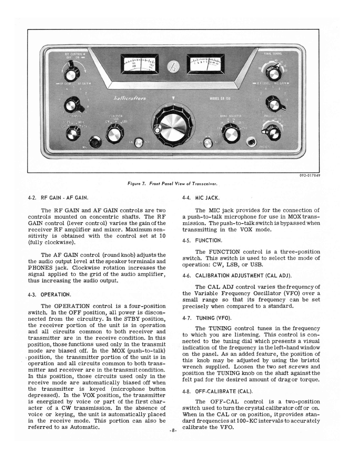
Connect
a
suitable
microphone
to
the
jack
provided
on
the
front
panel.
It
is
important
that
the
internal
wiring
of
the
microphone
be
as
shown
in
figure
6.
IMPORTANT
Before
proceeding,
refer
to
alignment
procedure,
paragraph
8-3,
for
bias
adjustment.
1111111111111111111111111111111111111111111111111t-
DASH BOARD
~--
,
\ ,
----
---",\\~\
\ \ \ \ \ \
\\\\\
000
,----).
\
\ \ \ , \
I'
\
\
\
TRANSMISSION HUMP
092·019687
Figure
4.
Installing
the
Moclel
MR·150 Mounting
Rack.
Only
after
familiarizing
yourself
with the
controls
and
their
functions,
as
outlined
in
Sections IV and
V,
should you
perform
an
opera-
tional check.
It
is
recommended
that
the engine
be
running
while
operating
the
Model SR-150
Trans-
ceiver
to
prevent
drainingpower
from
the
battery.
3·5.
MOBILE
NOISE
SUPPRESSION.
The following
suggestions
may
be
helpful
in
the
suppression
of
noise
encountered
in
mobile
operation.
Install
resistor-type
spark
plugs and
coaxial
bypass
capacitors
in
the
ignition
coil,
generator,
and voltage
regulator
leads.
Install
bracket-mounted
coaxial
capacitors
in
the
gener-
ator
and
battery
leads
to the voltage
regulator
and
connect
a 0.005
microfarad
mica
or
disc
capacitor
from
the
generator
lead
to ground. Chokes
maybe
used
in
the
generator
field
and
armature
leads
instead
of the
bypass
capacitors
-
approximately
12
turns
of
NO.
18
wire
on a
1/4-inch
powdered
iron
core
for
the field
lead
choke and
approxi-
mately
12
turns
of
NO.
12
or
NO.
14
wire
on a
1/4-inch
powdered
iron
core
for
the
armature
lead
choke.
·6·
Hallicrafters
has
available
a Mobile
Noise-
Suppression
Kit, Model HA-3, which will fulfill
any
suppression
requirements
of
this
installation.
Additional
information,
concerning
the
proper
suppression
of mobile
noise,
is
available
in
the
Handbook of
Instructions
for
Hallicrafters'
Model
HA-3 Mobile Noise Suppression Kit and
in
other
current
handbooks on the
same
subject.
3·6.
BASE
INSTALLATION.
The Model SR-150
Transceiver,
as
a
base
station,
may
be
used
with
or
without a
linear
amplifier.
To
operate
from
117
volts
AC, the
Model PS-150-120
Power
Supply,
or
an equivalent,
is
required.
Merely
connect
the
power plug
from
the
power supply to the
receptacle
on the
rear
of
the
transceiver,
connect the
AC
cord
from
the
power supply to the wall
outlet,
and connect to an
antenna
installation
as
described
in
paragraph
3-3.
A four by
six
inch
speaker
is
contained
in
the
power
supply and
is
interconnected
to the
trans-
ceiver
through
the
power plug.
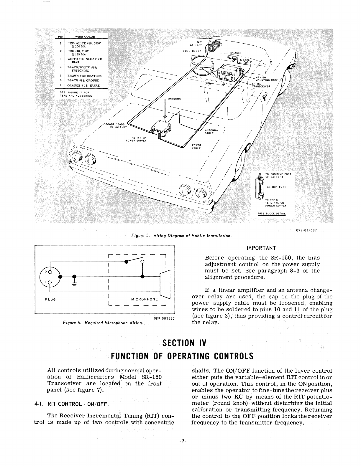
2
RED
#18; 250V
@175 MA
WHITE #18; NEGATIVE
BIAS
BLACK/WHITE
#18;
SWITCHING
BROWN #12; HEATERS
BLACK
#12; GROUND
ORANGE # 18;
SPARE
PS-150
-12
POWER SUPPLY
m
TO
POSITIVE POST
"
OF
BATTERY
I
30
AMP
FUSE
TO
TOP (+)
TERMIN,AL
ON
POWER SUPPLY
Figure
5.
Wiring Diagram
01
Mobile
Installation.
r-
--
-.
-
I
I
I
I
I
MICROPHONE
I
L_
---
-.J
PLUG
089·003330
Figure 6.
Required
Microphone Wiring.,
IMPORTANT
Before
operating
the
SR-150,
the
bias
adjustment
control
on
the
power
supply
must
be
set.
See
paragraph
8-3
of
the
alignment
procedure.
If
a
linear
amplifier
and an
antenna
change-
over
relay
are
used,
the
cap
on
the
plug
of
the
power
supply
cable
must
be
loosened,
enabling
wires
to
be
soldered
to
pins
10 and
11
of
the
plug
(see
figure
3),
thus
providing
a
control
circuit
for
the
relay.
..
.
SECTION
IV
FUNCTION
OF
OPERATING
CONTROLS
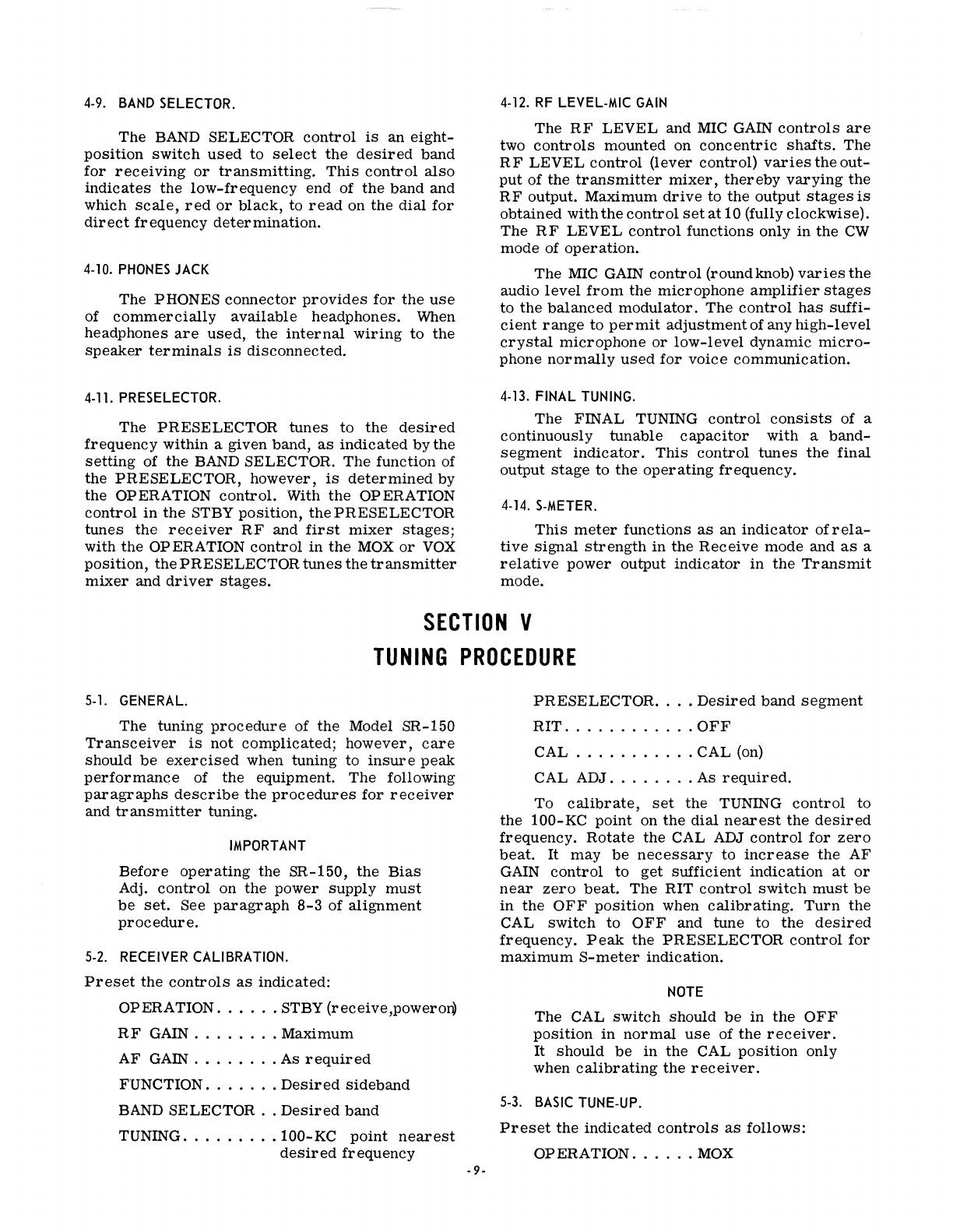
All
controls
utilized
during
normal
oper-
ation
of
Hallicrafters
Model
SR;;.150
Transceiver
are
located'
on
the
front
panel
(see
figure
7). .
4-1. RIT CONTROL -ON/OFF.
, :
.'
The
Receiver
Incremen.tal
Tuning
(RIT)
·con-
. . .
trol
is
made
up of two
controls;with
concentI:~c
-7-
shafts.
The
ON/OFF
function of
the
lever
control
either
puts
the
variable-element
RIT
control
in
or
out
of
operation.
This
control,
in
the
ON
position
,
enables
the
operator
to
fine-tune
the
receiver
plus
or
minus
two
KC
by
means
of
the
RIT
potentio-
meter
(round knob) without
disturbing
the.initial
calibration
or
tr.an~mitting
frequency.
Returning
the
control
to
the
OFF
position
locks
Ule
receiver
frequency
to
the
transmitter
frequency.
092-0
17
8
49
Figure
7.
Front Panel
View
of
Transceiver
.
4-2.
RF
GAIN
-
AF
GAIN.
The
RF
GAIN and
AF
GAIN
controls
are
two
controls
mounted
on
concentric
shafts.
The
RF
GAIN
control
(lever
contr
-ol)
varies
the
gain
of
the
receiver
RF
amplifier
and
mixer.
Maximum
sen-
sitivity
is
obtained
with
the
control
set
at
10
(fully
clockwise).
The
AF
GAIN
control
(round knob)
adjusts
the
the
audio
output
level
at
the
speaker
terminals
and
PHONES
jack.
Clockwise
rotation
increases
the
signal
applied
to
the
grid
of
the
audio
amplifier,
thus
increasing
the
audio output.
4-3.
OPERATION.
The
OPERATION
control
is
a
four-position
switch.
In
the
OFF
pOSition,
all
power
is
discon-
nected
from
the
circuitry.
In
the
STBY
position,
the
receiver
portion
of
the
unit
is
in
operation
and
all
circuits
common
to
both
receiver
and
transmitter
are
in
the
receive
condition. In
this
position,
those
functions
used
only
in
the
transmit
mode
are
biased
off.
In
the
MOX
(push-to-talk)
,
position,
the
transmitter
portion
of
the
unit
is
in
operation
and
all
circuits
common
to
both
trans-
mitter
and
receiver
are
in
the
transmit
condition.
In
this
pOSition,
those
circuits
used
only
in
the
receive
mode
are
automatically
biased
off when
the
transmitter
is
keyed
(microphone
button
depressed).
In
the
VOX
position,
the
transmitter
is
energized
by
voice
or
part
of
the
first
char-
acter
of a CW
transmission.
In
the
absence
of
voice
or
keying,
the
unit
is
automatically
placed
in
the
receive
mode.
This
portion
can
also
be
referred
to
as
Automatic.
4-4
.
MIC
JACK.
The
MIC
jack
provides
for
the
connection
of
a
push-to-talk
microphone
for
use
in
MOXtrans-
mission.
Thepush-to-talk
switch
is
bypassed
when
transmitting
in
the
VOX
mode.
4-5.
FUNCTION.
The
FUNCTION
control
is
a
three-position
switch.
This
switch
is
used
to
select
the
mode
of
operation:
CW, LSB,
or
USB.
4-6.
CALIBRATION
ADJUSTMENT
(CAL
ADJ)
.
The
CAL ADJ
control
varies
the
frequency
of
the
Variable
Frequency
Oscillator
(VFO)
over
a
small
range
so
that
its
frequency
can
be
set
precisely
when
compared
to a
standard.
4-7.
TUNING
(VFO).
The
TUNING
control
tunes
in
the
frequency
to which you
are
listening.
This
control
is
con-
nected
to
the
tuning
dial
which
presents
a
visual
indication
of
the
frequency
in
the
left-hand
window
on
the
panel.
As
an
added
feature,
the
position
of
this
knob
may
be
adjusted
by
using
the
bristol
wrench
supplied.
Loosen
the
two
set
screws
and
position
the
TUNING knob on
the
shaft
against
the
felt
pad
for
the
desired
amount
of
dragor
torque.
4-8.
OFF-CALI
BRA
TE
(CAL).
The
OFF-CAL
control
is
a
two-position
switch
used
to
turn
the
crystal
calibrator
off
or
on.
When
in
the
CAL
or
on
position,
it
provides
stan-
dard
frequencies
at
100-KC
intervals
to
accurately
-8-
calibrate
the
VFO.
4-9. BAND SELECTOR.
The
BAND SELECTOR
control
is
an
eight-
position
switch
used
to
select
the
desired
band
for
receiving
or
transmitting.
This
control
also
indicates
the
low-frequency
end of
the
band
and
which
scale,
red
or
black,
to
read
on
the
dial
for
direct
frequency
determination.
4-10.
PHONES
JACK
The
PHONES
connector
provides
for
the
use
of
commercially
available
headphones.
When
headphones
are
used,
the
internal
wiring
to
the
speaker
terminals
is
disconnected.
4-11.
PRESELECTOR.
The
PRESELECTOR
tunes
to
the
desired
frequency
within a given
band,
as
indicated
by
the
setting
of
the
BAND SELECTOR.
The
function of
the
PRESELECTOR,
however,
is
determined
by
the
OPERATION
control.
With
the
OPERATION
control
in
the
STBY
position,
the
PRESELECTOR
tunes
the
receiver
RF
and
first
mixer
stages;
with
the
OPERATION
control
in
the
MOX
or
VOX
position,
the
PRESELECTOR
tunes
the
transmitter
mixer
and
driver
stages.
4-12.
RF
LEVEL-MIC
GAIN
The
RF
LEVEL
and MIC GAIN
controls
are
two
controls
mounted
on
concentric
shafts.
The
RF
LEVEL
control
(lever
control)
varies
the
out-
put
of
the
transmitter
mixer,
thereby
varying
the
RF
output.
Maximum
drive
to
the
output
stages
is
obtained
with
the
control
set
at
10 (fully
clockwise).
The
RF
LEVEL
control
functions
only
in
the
CW
mode
of
operation.
The
MIC
GAIN
control
(round knob)
varies
the
audio
level
from
the
microphone
amplifier
stages
to
the
balanced
modulator.
The
control
has
suffi-
cient
range
to
permit
adjustment
of any
high-level
crystal
microphone
or
low-level
dynamic
micro-
phone
normally
used
for
voice
communication.
4-13.
FINAL
TUNING.
The
FINAL TUNING
control
consists
of a
continuously
tunable
capacitor
with
a
band-
segment
indicator.
This
control
tunes
the
final
output
stage
to
the
operating
frequency.
4-14. S-METER.
This
meter
functions
as
an
indicator
of
rei
a-
tive
signal
strength
in
the
Receive
mode
and
as
a
relative
power
output
indicator
in
the
Transmit
mode.
SECTION
V
TUNING
PROCEDURE
5-1. GENERAL.
The
tuning
procedure
of
the
Model SR-150
Transceiver
is
not
complicated;
however,
care
should
be
exercised
when tuning to
insure
peak
performance
of
the
equipment.
The
following
paragraphs
describe
the
procedures
for
receiver
and
transmitter
tuning.
IMPORTANT
Before
operating
the
SR-150,
the
Bias
Adj.
control
on
the
power
supply
must
be
set.
See
paragraph
8-3
of
alignment
procedure.
5-2. RECEIVER CALIBRATION.
Preset
the
controls
as
indicated:
OPERATION
......
STBY
(receive,powero~
RF
GAIN
........
Maximum
AF
GAIN
........
As
required
FUNCTION
.......
Desired
sideband
BAND SELECTOR
..
Desired
band
TUNING
.........
100-KC
point
nearest
desired
frequency
-9-
PRESELECTOR
....
Desired
band
segment
RIT
............
OFF
CAL
...........
CAL (on)
CAL ADJ
........
As
required.
To
calibrate,
set
the
TUNING
control
to
the
100-KC
point
on
the
dial
nearest
the
desired
frequency.
Rotate
the
CAL ADJ
control
for
zero
beat.
It
may
be
necessary
to
increase
the
AF
GAIN
control
to
get
sufficient
indication
at
or
near
zero
beat.
The
RIT
control
switch
must
be
in
the
OFF
position
when
calibrating.
Turn
the
CAL
switch
to
OFF
and tune
to
the
desired
frequency.
Peak
the
PRESELECTOR
control
for
maximum
S-meter
indication.
NOTE
The CAL
switch
should
be
in
the
OFF
pOSition
in
normal
use
of
the
receiver.
It
should
be
in
the
CAL
position
only
when
calibrating
the
receiver.
5-3. BASIC TUNE-UP.
Preset
the
indicated
controls
as
follows:
OPERATION
......
MOX
FINAL TUNING
....
Desired
band
segment
FUNCTION
.......
CW
BAND
SELECTOR
..
Desired
band
TUNING
.........
Desired
frequency
PRESELECTOR
...
Desired
band
segment
RF
LEVEL
..
-
....
Between 4 and 5,
or
as
required.
Adjust the
RF
LEVEL
control
until a
small
indication
is
seen
on the
S-meter.
In
the
transmit
mode, the
S-meter
indicates
relative
RF
output
voltage. Adjust the FINAL TUNING control
for
maximum
output and then
adjust
the
PRESELEC-
TOR
for
maximum
output indication.
AdjusttheRF
LEVEL
control
as
required
to keep the
S-meter
reading
below S9, while tuning the PRESELECTOR.
5-4.
MANUAL
CW
OPERATION.
Use the
procedure
as
given in
paragraphs
5-2
and 5-3. (If a key
is
plugged into the Key
jack,
J5,
it
must
be
closed.)
AdvancetheRFLEVELcontrol
to
just
below.
saturated
output.
Saturated
output
is
determined
in
the following
manner.
start
at
"0"
settingoftheRF
LEVEL con-
trol
and slowly
increase
the
control
(clockwise)
while
observing
the
S-meter.
Set
the
control
at
a
point
where
further
rotation
does
not
cause
an
ap-
preciable
increase
in
the
S-meter
reading.
This
is
saturated
output;
operate
slightly
below
this
level.
The
transmitter
is
now
ready
to key. To
receive,
it
is
necessary
to
turn
the
OPERATION
switch
to the STBY position.
5-5.
BREAK-IN
CW
OPERATION.
Use the tuning
procedure
as
given in
para-
graphs
5-2, 5-3,
and 5-4. Set the OPERATION
-10-
switch
to the
VOX
position. Adjust the
delay
control
(see
figure
12)
for
the
desired
drop-out
delay;
delay
increases
with clockwise
rotation.
Theunit
is
now
ready
for
break-in
CW
operation.
5-6.
PUSH-
TO-TALK
SSB
OPERATION
(MOX).
Use the
procedure
given in
paragraphs
5-2,
5-3,
and 5-4. Set
the
FUNCTION switch to the
de-
sired
sideband
(USB
or
LSB). SettheOPERATION
switch
to
MOX.
Depress
the
microphone
switch
(push-to-talk) and advance
the
MIC
GAIN
control
(while speaking into the microphone
in
a
normal
voice level) until the
S-meter
indicates
approxi-
mately
one-half the
level
shown
at
saturation.
The
MIC
GAIN
setting
is
not
critical,
because
of
the
action of the AALC
circuitry,
and may
be
advanced
slightly
beyond
this
point to
increase
compression.
Typical
settings
will
run
from
5 to 8.
5-7.
VOICE
CONTROLLED
SSB
OPERATION
(MOX).
For
voice
operated
transmission,
use
the
tuning
procedure
in
paragraphs
5-2, 5-3,
and 5-4.
Set the FUNCTION
switch
to the
desired
sideband
(USB
or
LSB). Set the OPERATION
switch
to the
VOX
position. Set
the
receiver
AF
GAIN
to
"0"
or
a low level. While speaking into the microphone,
advance the
VOX
gain
control
clockwise (see
figure
12) until the
VOX
relay
closes;
use
no
more
VOX
gain than
necessary.
Adjust the delay
control
for
the
desired
drop-out
delay; delay
time
increases
with clockwise
rotation.
It
may
be
necessary
to
re-
adjust
the
VOX
gain
slightly
because
of
interaction
between the
controls.
Adjust
the
receiver
AF
GAIN
to the
desired
listening
level. Advance the QT
(anti-trip)
control
(see figure 12) clockwise until
received
signals
do not
actuate
the VOXrelay. Use
no
more
anti-trip
gain than
necessary.
SECTION
VI
THEORY
OF
OPERATION
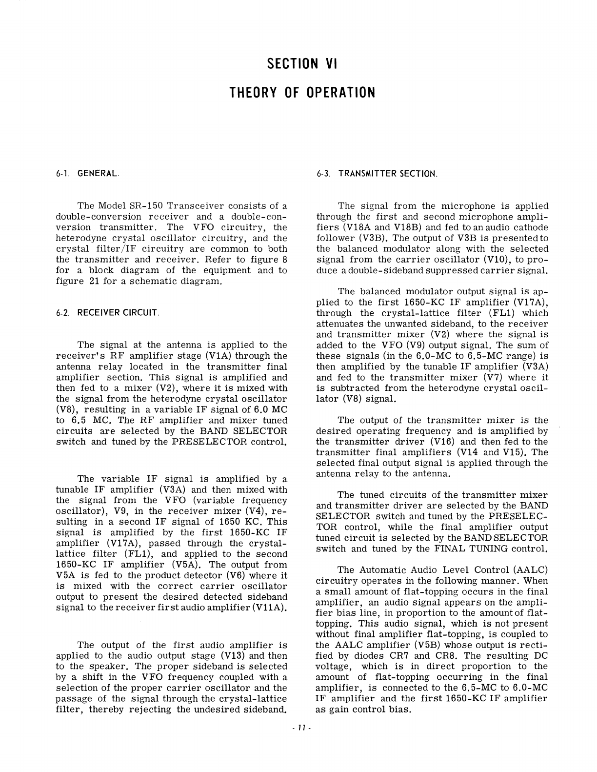
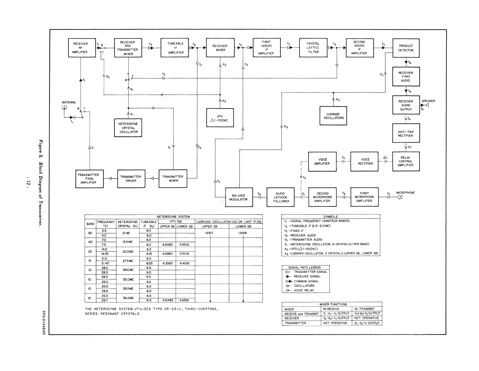
6-1.
GENERAL.
The
Model
SR-150
Transceiver
consists
of
a
double-conversion
receiver
and a
double-con-
version
transmitter.
The
VFO
circuitry,
the
heterodyne
crystal
oscillator
circuitry,
and
the
crystal
filter/IF
circuitry
are
common
to
both
the
transmitter
and
receiver_Refer
to
figure
8
for
a
block
diagram
of
the
equipment
and
to
figure
21
for
a
schematic
diagram_
6-2.
RECEIVER
CIRCUIT.
The
signal
at
the
antenna
is
applied
to
the
receiver's
RF
amplifier
stage
(VIA)
through
the
antenna
relay
located
in
the
transmitter
final
amplifier
section.
This
signal
is
amplified
and
then
fed
to
a
mixer
(V2),
where
it
is
mixed
with
the
signal
from
the
heterodyne
crystal
oscillator
(V8),
resulting
in
a
variable
IF
signal
of
6.0
MC
to
6.5
MC.
The
RF
amplifier
and
mixer
tuned
circuits
are
selected
by
the
BAND
SELECTOR
switch
and
tuned
by
the
PRESELECTOR
control.
The
variable
IF
signal
is
amplified
by
a
tunable
IF
amplifier
(V3A)
and
then
mixed
with
the
signal
from
the
VFO
(variable
frequency
oscillator),
V9,
in
the
receiver
mixer
(V4),
re-
sulting
in
a
second
IF
signal
of
1650 KC.
This
signal
is
amplified
by
the
first
1650-KC
IF
amplifier
(VI7A),
passed
through
the
crystal-
lattice
filter
(FLl),
and
applied
to
the
second
1650-KC
IF
amplifier
(V5A).
The
output
from
V5A
is
fed
to
the
product
detector
(V6)
where
it
is
mixed
with
the
correct
carrier
oscillator
output
to
present
the
desired
detected
sideband
signal
to
the
receiver
first
audio
amplifier
(VllA).
The
output
of
the
first
audio
amplifier
is
applied
to
the
audio
output
stage
(VI3)
and
then
to
the
speaker.
The
proper
sideband
is
selected
by
a
shift
in
the
VFO
frequency
coupled
with
a
selection
of
the
proper
carrier
oscillator
and
the
passage
of
the
signal
through
the
crystal-lattice
filter,
thereby
rejecting
the
undesired
sideband.
-
11
-
6-3.
TRANSMITTER
SECTION.
The
signal
from
the
microphone
is
applied
through
the
first
and
second
microphone
ampli-
fiers
(VI8A and
VI8B)
and fed to an audio
cathode
follower
(V3B).
The
output
of
V3B
is
presented
to
the
balanced
modulator
along with
the
selected
signal
from
the
carrier
oscillator
(VI0),
to
pro-
duce
a
double-
sideband
suppressed
carrier
signal.
The
balanced
modulator
output
signal
is
ap-
plied
to
the
first
1650-KC
IF
amplifier
(VI7A),
through
the
crystal-lattice
filter
(FLl)
which
attenuates
the
unwanted
sideband,
to
the
receiver
and
transmitter
mixer
(V2)
where
the
signal
is
added
to
the
VFO (V9)
output
signal.
The
sum
of
these
signals
(in
the
6.0-MC
to
6.5-MC
range)
is
then
amplified
by
the
tunable
IF
amplifier
(V3A)
and
fed
to
the
transmitter
mixer
(V7)
where
it
is
subtracted
from
the
heterodyne
crystaloscil-
lator
(V8)
signal.
The
output
of
the
transmitter
mixer
is
the
desired
operating
frequency
and
is
amplified
by
the
transmitter
driver
(VI6)
and
then
fed
to
the
transmitter
final
amplifiers
(V14
and
VI5).
The
selected
final
output
signal
is
applied
through
the
antenna
relay
to
the
antenna.
The
tuned
circuits
of
the
transmitter
mixer
and
transmitter
driver
are
selected
by
the
BAND
SELECTOR
switch
and
tuned
by
the
PRESELEC-
TOR
control,
while
the
final
amplifier
output
tuned
circuit
is
selected
by
the
BAND
SELECTOR
switch
and
tuned
by
the
FINAL TUNING
control.
The
Automatic
Audio
Level
Control
(AALC)
circuitry
operates
in
the
following
manner.
When
a
small
amount
of
flat-topping
occurs
in
the
final
amplifier,
an
audio
Signal
appears
on
the
ampli-
fier
bias
line,
in
proportion
to
the
amount
of
flat-
topping.
This
audio
signal,
which
is
not
present
without
final
amplifier
flat-topping,
is
coupled
to
the
AALC
amplifier
(V5B)
whose
output
is
recti-
fied
by
diodes
CR7
and
CR8.
The
resulting
DC
voltage,
which
is
in
direct
proportion
to
the
amount
of
flat-topping
occurring
in
the
final
amplifier,
is
connected
to
the
6.5-MC
to
6.0-MC
IF
amplifier
and
the
first
1650-KC
IF
amplifier
as
gain
control
bias.
"'11
.0'
t:
;0
?>
OJ
0-
n
,...
t:l
;:::;
Q'
'"
a
"
0
...
-I
a
"
In
n
..
<'
~
RECEIVER
I, R RECEIVER
12
TUNEABLE
I.
FIRST
AND
RECEIVER
13
1650KC
RF
IF
AMPLIFIER TRANSMITTER MIXER
IF
T MIXER AMPLIFIER AMPLIFIER
f2
X2
f3
X2
T
f3
I,
R
X,
ANTENNA X2
I
R~
X,
VFO
6f
~500KC
f,
HETERODYNE
CRYSTAL
OSCILLATOR
I,
X,
12
TRANSMITTER
f---<r-
TRANSMITTER
~
TRANSMITTER
FINAL -
AMPLIFIER
DRIVER
MIXER
f,
--+-
-BALANCE
MODULATOR
HETERODYNE
SYSTEM
BAND
FREQUENCY
HETERODYNE TUNEABLE
VFO
(X2)
CARRIAGE
OSCILLATOR
(X,)
OR
LAST
IF(I,)
(f,)
CRYSTAL
(X,) IF
(12)
UPPER
SB
LOWER
SB
UPPER
S8
80
3,5
4.0
10MC
6.5
1.6517
6.0
40
7.0 13.5MC
6.5
7.3 6.2
4.5483
4.5519
20
14.0
6.5
14.35 20.5MC
6.15
4.4983
4.5019
15
21.0
6.5
27.5MC
21.45
6.05
4.3983
4.4019
10
28.0
34.5MC
6.5
28.5
6.0
28.5
6.5
10
29.0
35.0MC
6.0
10
29.0 35.5MC
6.5
29.5
6.0
29.5
36.0MC
6.5
10
29.7
6.3
4.6519
4.6483
THE
HETERODYNE
SYSTEM
UTILIZES
TYPE
CR-23/U,
THIRD-OVERTONE,
SERIES
-RESONANT
CRYSTALS.
LOWER
SB
1.6481
f3
CRYSTAL
f3
SECOND
13
1650KC
LATTICE IF
FILTER AMPLIFIER
.--
X3
tX3
CARRIER
OSCILLATORS
X,
15
DC
VOICE
VOICE
,-
AMPLIFIER
->--
RECTIFIER
I-
->-
I
Af5
I
I
AUDIO
~
SECOND
f5
CATHODE
MICROPHONE
----<l-
FOLLOWER AMPLIFiER
SYMBOLS
r
f
~SIGNAL
FREQUENCY
(AMATEUR BANDS)
I~
~TUNEABLE
IF(6.5-6.0MC)
I
I,
~FIXED
IF
•
f.
~RECEIVER
AUDIO
f5
~TRANSMITTER
AUDIO
FIRST
MICROPHONE
AMPLIFIER
X,
~HETERODYNE
OSCILLATOR. 8
CRYSTALS
(I
PER
BAND)
X.
~VFO(61~500KC)
X,
~CARRIER
OSCILLATOR. 2 CRYSTALS (UPPER S8.
LOWER
S81
SIGNAL
PATH
LEGEND
-{>-
TRANSMITTER SIGNAL
-.-
RECEIVER SIGNAL
~
COMMON
SIGNAL
...:;.- OSCILLATORS
-;.-
VOICE
RELAY
MIXER FUNCTIONS
MIXER
IN
RECEIVE
RECEIVE and TRANSMIT f,
Xl;:;
f2
OUTPUT
RECEIVER
f2.
X2-=
f3 OUTPUT
TRANSMITTER
NOT
OPERATIVE
---.
___________
~
_
______'=_'_'__=__-o-
IN
TRANSMIT
f,+X2~
12
OUTPUT
NOT OPERATIVE
XI-f2~f,
OUTPUT
15
PRODUCT
DETECTOR
tf.
RECEIVER
FIRST
AUDIO
tf
•
RECEIVER SPEA
KER
AUDIO
~
OUTPUT
,
yf.
I
ANTI-TRIP
RECTIFIER
I
YDC
I
RELAY
CONTROL
AMPLIFIER
MICROPHONE
SECTION
VII
SERVICE
DATA
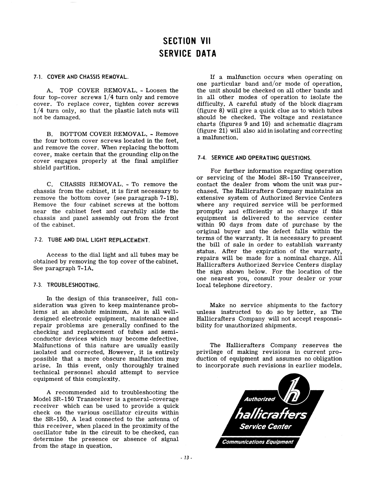
7-1.
COVER
AND
CHASSIS
REMOVAL.
A.
TOP COVER REMOVAL. -
Loosen
the
four
top-cover
screws
1/4
turn
only and
remove
cover.
To
replace
cover,
tighten
cover
screws
1/4
turn
only,
so
that
the
plastic
latch
nuts
will
not
be
damaged.
B. BOTTOM COVER REMOVAL. -Remove
the four
bottom
cover
screws
located
in the feet,
and
remove
the
cover.
When
replacing
the
bottom
cover,
make
certain
that
the
grounding clip on the
cover
engages
properly
at
the final
amplifier
shield
partition.
C.
CHASSIS
REMOVAL. -To
remove
the
chassis
from
the cabinet,
it
is
first
necessary
to
remove
the bottom
cover
(see
paragraph
7-1B).
Remove the four cabinet
screws
at
the bottom
near
the
cabinet
feet and
carefully
slide
the
chassis
and
panel
assembly
out
from
the
front
of the cabinet.
7-2.
TUBE
AND
DIAL
LIGHT
REPLACEMENT.
Access
to the
dial
light and
all
tubes
may
be
obtained by
removing
the top
cover
of the cabinet.
See
paragraph
7-1A.
7-3.
TROUBLESHOOTING.
In
the
design
of
this
transceiver,
full
con-
sideration
was
given to keep maintenance
prob-
lems
at
an absolute minimum. As
in
all
well-
designed
electronic
equipment, maintenance and
repair
problems
are
generally
confined to
the
checking and
replacement
of
tubes
and
semi-
conductor
devices
which
may
become
defective.
Malfunctions of
this
nature
are
usually
easily
isolated
and
corrected.
However,
it
is
entirely
possible
that
a
more
obscure
malfunction
may
arise.
In
this
event, only thoroughly
trained
technical
personnel
should
attempt
to
service
eqUipment of
this
complexity.
A
recommended
aid
to troubleshooting the
Model SR-150
Transceiver
is
ageneral-coverage
receiver
which can
be
used
to
provide
a quick
check
on the
various
oscillator
circuits
within
the SR-150. A
lead
connected to the antenna
of
this
receiver,
when
placed
in
the
proximity
ofthe
oscillator
tube in the
circuit
to
be
checked,
can
determine
the
presence
or
absence
of
signal
from
the
stage
in
question.
-
13
-
If
a malfunction
occurs
when
operating
on
one
particular
band
and/or
mode of
operation,
the
unit
should
be
checked on
all
other
bands
and
in
all
other
modes
of
operation
to
isolate
the
difficulty. A
careful
study of the block
diagram
(figure
8)
will give a quick clue
as
to which
tubes
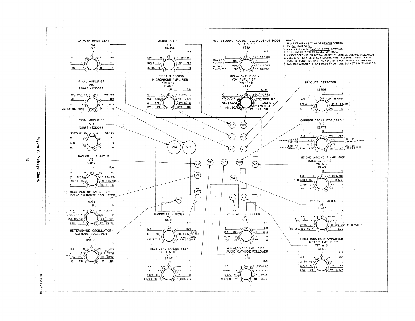
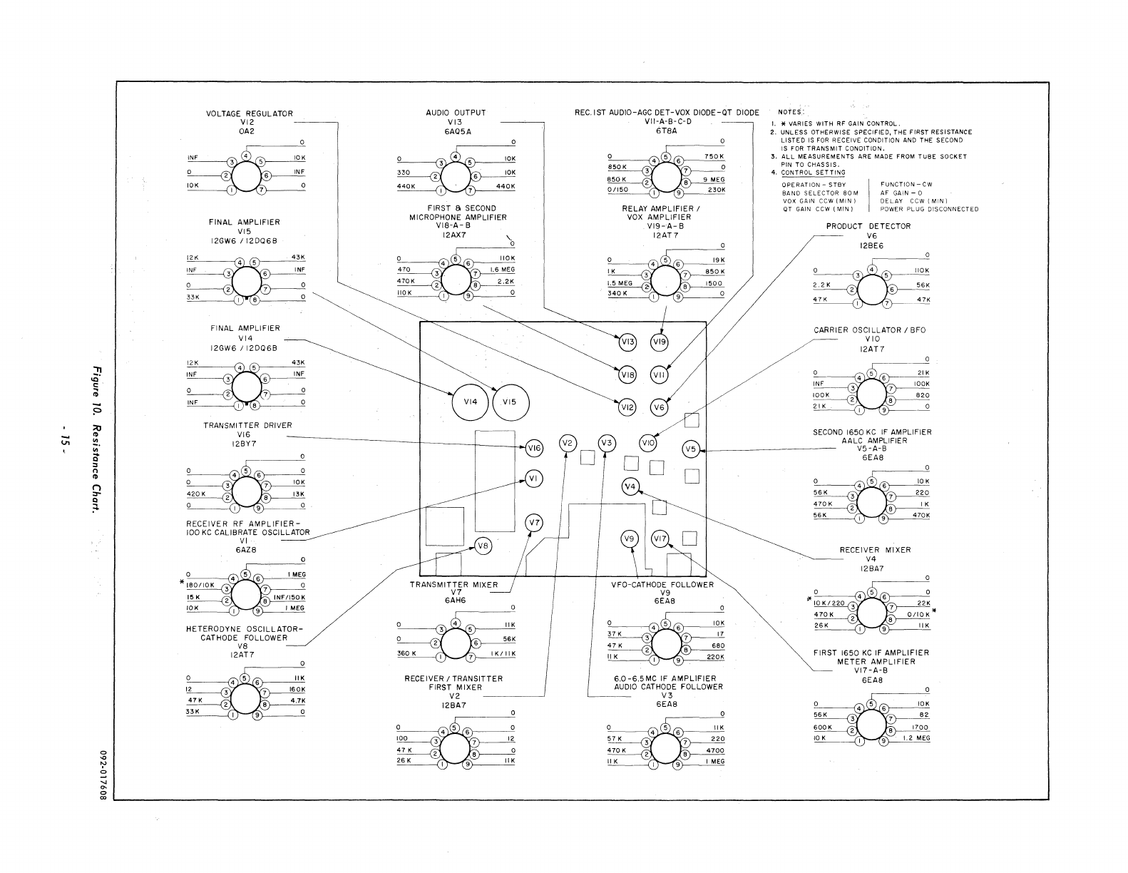
should be checked. The voltage and
resistance
charts
(figures 9 and 10) and
schematic
diagram
(figure 21) will
also
aid
in
isolating
and
correcting
a malfunction.
7-4.
SERVICE
AND
OPERATING
QUESTIONS.
For
further
information
regarding
operation
or
servicing
of the Model SR-150
Transceiver,
contact
the
dealer
from
whom the
unit
was
pur-
chased.
The
Hallicrafters
Company
maintains
an
extensive
system
of Authorized
Service
Centers
where
any
required
service
will
be
performed
promptly
and efficiently
at
no
charge
if
this
equipment
is
delivered
to the
service
center
within
90
days
from
date of
purchase
by the
original
buyer
and
the
defect
falls
within the
terms
of the
warranty.
It
is
necessary
to
present
the
bill
of
sale
in
order
to
establish
warranty
status.
After
the
expiration
of the
warranty,
repairs
will be
made
for
a nominal
charge.
All
Hallicrafters
Authorized
Service
Centers
display
the
sign
shown below.
For
the
location
of the
one
nearest
you,
consult
your
dealer
or
your
local
telephone
directory.
Make no
service
shipments
to the
factory
unless
instructed
to do
so
by
letter,
as
The
Hallicrafters
Company will
not
accept
responsi-
bility
for
unauthorized
shipments.
The
Hallicrafters
Company
reserves
the
privilege
of making
revisions
in
current
pro-
duction of equipment and
assumes
no obligation
to
incorporate
such
revisions
in
earlier
models.
<
!!..
Q
<Q
<D
n
:r-
Q
;::.
o
'"
~
o
"
'"
o
"
III
VOLTAGE
REGULATOR
VIZ
---~
OA2
FINAL
AMPLIFIER
VI5
12GW6
/12D06B
FINAL AMPLIFIER
VI4
12GW6
/12DQ6B
TRANSMITTER DRIVER
VI6
128Y7
RECEIVER
RF
AMPLIFIER
100
KC
CALIBRATE OSCILLATOR
VI
6AZS
HETERODYNE
OSCILLATOR-
CATHODE FOLLOWER
VS
12AT7
H 0
12.6
AUDIO
OUTPUT
VI3
6A05A
FIRST a
SECOND
MICROPHONE AMPLIFIER
VIS
A-8
12AX7
RECEIVER / TRANSMITTER
FIRST MIXER
V2
-----~
12BA7
H
12.6
REc.tST
AUDIO-AGC DET-VOX
DIODE
-aT
DIODE
VII-A-B-C-D
6TSA
RELAY AMPLIFIER /
vox
AMPLIFIER
V19-
A-
8
12AT7
NOTES:
I.
* VARIES WITH
SETTING
of
RF
GAIN
CONTROL.
2.
'**
CAL
SWITCH
ON.
--
3.
iE*iVARIES
WITHBAND
SELECTOR
SETTING.
4.
****
VARIES
WITH RF
LEVEL
CONTROL.
5.
*****
DEPENDS
ON~
ACTIVITY
(NOMINAL
VOLTAGE
INDICATED)
6,
UNLESS
OTHERWISE
SPECIFIED,THE
FIRST
VOLTAGE
LISTED
IS
FOR
RECEIVE
CONDITION AND
THE
SECOND IS FOR
TRANSMIT
CONDITION.
1~
ALL
MEASUREMENTS
ARE
MADE
FROM
TUBE
SOCKET
PIN TO CHASSIS,
PRODUCT
DETECTOR
V6
12BE6
CARRIER OSCILLATOR / BFO
VIO
12AT7
t~~tk~o
*****
,
,,"
,_",,-
t~~ti.;
H***
SECOND
1650
KC
IF AMPLIFIER
AALC AMPLIFIER
}.oI-----------
V5
-A-B
VFO-CATHODE FOLLOWER
V9
6EAS
H
6.0-6.5MC
IF AMPLIFIER
AUDIO CATHODE FOLLOWER
'-----
V3
6EAS
12.6
6EAS
RECEIVER MIXER
V4
12BA7
. .
=,-,-,,"2-,-,,2c'.'IIC"O~
13
(TIE
POINT)
260
FIRST
1650
KC
IF AMPLIFIER
METER
AMPLIFIER
VI7-A-B
6EAS
~
..
::!.
'"
Q
:0
n
..
n
=-
Q
;.:.
VOLTAGE REGULATOR
VI2
-----,
OA2
FINAL
AMPLIFIER
VI5
12GW6 f
12D06S
FINAL AMPLIFIER
VI4
12GW6
/I2D068
TRANSMITTER DRIVER
VI6
12Sn
RECEIVER RF
AMPLIFIER-
100
KC
CALIBRATE OSCILLATOR
VI
6AZ8
HETERODYNE
OSCILLATOR-
CATHODE FOLLOWER
V8
12AT7
AUDIO OUTPUT
VI3
6A05A
FIRST S
SECOND
MICROPHONE AMPLIFIER
VIS-A-
8
12AX7
RECEIVER f
TRANSITTER
FIRST
MIXER
V2
____
.-.J
128A7
REC.IST AUDIO-AGe DET-VOX
DIODE-aT
DIODE
VII'A'B-C-D
6T8A
RELAY
AMPLIFIER
f
vox
AMPLIFIER
VI9-A-
B
IZAT7
6.0-6.5MC
IF
AMPLIFIER
AUDIO
CATHODE FOLLOWER
V3
6EAS
NOTES'
I. *
VARIES
WITH
RF
GAIN
CONTROL.
2.
UNLESS
OTHERWISE
SPECIFIED,
THE
FIRST
RESISTANCE
LlSTE'O
IS FOR
RECEIVE
CONDITION
AND
THE
SECOND
IS
FOR
TRANSMIT
CONDITION.
3.
ALL
MEASUREMENTS
ARE
MADE
FROM
TUBE
SOCKET
PIN
TO
CHASSIS.
4. CONTROL
SETTING
OPERATION
-
STBY
BAND
SELECTOR
80
M
VOX
GAIN
CCW
(MIN)
aT
GAIN CCW
(MIN)
FUNCTION
-cw
AFGAIN-Q
DELAY
CCW
(MIN)
POWER
PLUG
DISCONNECTED
PRODUCT DETECTOR
V6
128E6
56K
47K
CARRIER OSCILLATOR I BFO
VIO
12AT7
21 K
SECOND
1650
KC
IF
AMPLIFIER
AALC AMPLIFIER
V5
-A-B
6EAS
RECEIVER MIXER
V4
12BA7
FIRST 1650
KC
IF
AMPLIFIER
METER
AMPLI FIER
VI7-A-S
6EAS
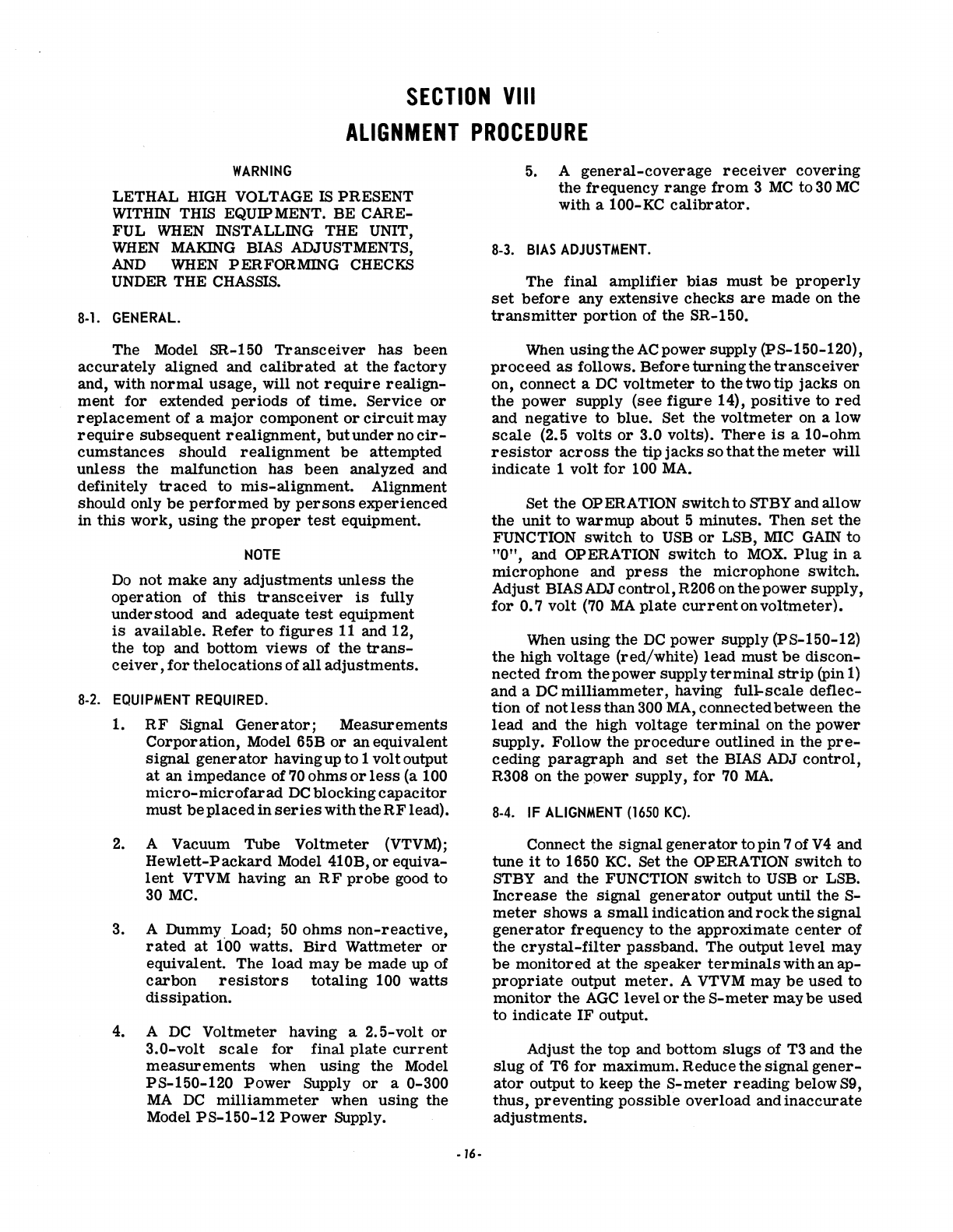
SECTION
VIII
ALIGNMENT
PROCEDURE
WARNING
LETHAL
HIGH
VOLTAGE
IS
PRESENT
WITHIN
THIS EQUIP MENT. BE CARE-
FUL
WHEN
INSTALLING THE UNIT,
WHEN
MAKING
BIAS
ADJUSTMENTS,
AND
WHEN
PERFORMING CHECKS
UNDER
THE
CHASSIS.
8·1.
GENERAL.
The Model SR-150
Transceiver
has
been
accurately
aligned and
calibrated
at
the
factory
and, with
normal
usage,
will not
require
realign-
ment
for
extended
periods
of
time.
Service
or
replacement
of a
major
component
or
circuit
may
require
subsequent
realignment,
but
under
no
cir-
cumstances
should
realignment
be
attempted
unless
the malfunction
has
been
analyzed and
definitely
traced
to
miS-alignment. Alignment
should only
be
performed
by
persons
experienced
in
this
work,
using
the
proper
test
equipment.
NOTE
Do
not
make
any
adjustments
unless
the
operation
of
this
transceiver
is
fully
under stood and adequate
test
equipment
is
available.
Refer
to
figures
11
and 12,
the top and bottom views of
the
trans-
ceiver,
for
thelocations of
all
adjustments.
8·2.
EQUIPMENT
REQUIRED.
1.
RF
Signal
Generator;
Measurements
Corporation,
Model 65B
or
an equivalent
signal
generator
having up to 1 volt output
at
an impedance of
70
ohms
or
less
(a 100
micro-microfarad
DC
blocking
capacitor
must
be
placed
in
serieswiththeRF
lead).
2.
A Vacuum Tube Voltmeter (VTVM);
Hewlett-Packard
Model 410B,
or
equiva-
lent
VTVM having an
RF
probe
good to
30
MC.
3. A Dummy. Load;
50
ohms
non-reactive,
rated
at
100 watts.
Bird
Wattmeter
or
equivalent. The load
may
be
made up of
carbon
resistors
totaling 100
watts
diSSipation.
4. A
DC
Voltmeter having a 2.5-volt
or
3.0-volt
scale
for final
plate
current
measurements
when
using
the
Model
PS-150-120
Power
Supply
or
a 0-300
MA
DC
milliammeter
when
using
the
Model
PS-150-12
Power
Supply.
·16·
5.
A
general-coverage
receiver
covering
the frequency
range
from
3
MC
to
30
MC
with a 100-KC
calibrator.
8·3.
BIAS
ADJUSTMENT.
The final
amplifier
bias
must
be
properly
set
before
any extensive
checks
are
made on
the
transmitter
portion
of the SR-150.
When
using
the
ACpower supply (pS-150-120),
proceed
as
follows. Before
turning
the
transceiver
on, connect a
DC
voltmeter
to
the
two tip
jacks
on
the
power supply (see
figure
14),
positive
to
red
and negative
to
blue. Set
the
voltmeter
on a low
scale
(2.5 volts
or
3.0 volts).
There
is
a
10-ohm
resistor
across
the
tip
jacks
so
that
the
meter
will
indicate 1 volt
for
100
MA.
Set
the
OPERATION
switch
to STBY and allow
the
unit
to
warmup about 5 minutes. Then
set
the
FUNCTION
switch
to
USB
or
LSB,
MIC
GAIN
to
"0",
and OPERATION switch
to
MOX.
Plug
in a
microphone and
press
the
microphone switch.
Adjust BIAS ADJ control, R206 on
the
power supply,
for
0.7
volt
(70
MA
plate
current
on
voltmeter).
When
using
the
DC
power supply (PS-150-12)
the
high voltage (red/white)
lead
must
be
discon-
nected
from
the
power supply
terminal
strip
(pin
1)
and a
DC
milliammeter,
having full-scale
deflec-
tion
of not
less
than 300
MA,
connected between the
lead
and the high voltage
terminal
on the power
supply. Follow
the
procedure
outlined in
the
pre-
ceding
paragraph
and
set
the
BIAS ADJ
control,
R308 on
the
power supply,
for
70
MA.
8·4.
IF
ALIGNMENT
(1650
KC).
Connect the
signal
generator
to
pin
7 of V 4 and
tune
it
to 1650
KC.
Set
the
OPERATION switch
to
STBY and the FUNCTION switch
to
USB
or
LSB.
Increase
the
signal
generator
output until the
S-
meter
shows a
smallindication
and
rock
the
signal
generator
frequency to
the
approximate
center
of
the
crystal-filter
passband. The output
level
may
be
monitored
at
the
speaker
terminals
with an
ap-
propriate
output
meter.
A VTVM may
be
used
to
monitor
the
AGC
level
or
the
S-meter
maybe
used
to
indicate
IF
output.
Adjust the top and bottom
slugs
of T3 and
the
slug
of T6
for
maximum. Reduce
the
signal
gener-
ator
output to keep the
S-meter
reading
below S9,
thus,
preventing
possible
overload
and
inaccurate
adjustments.
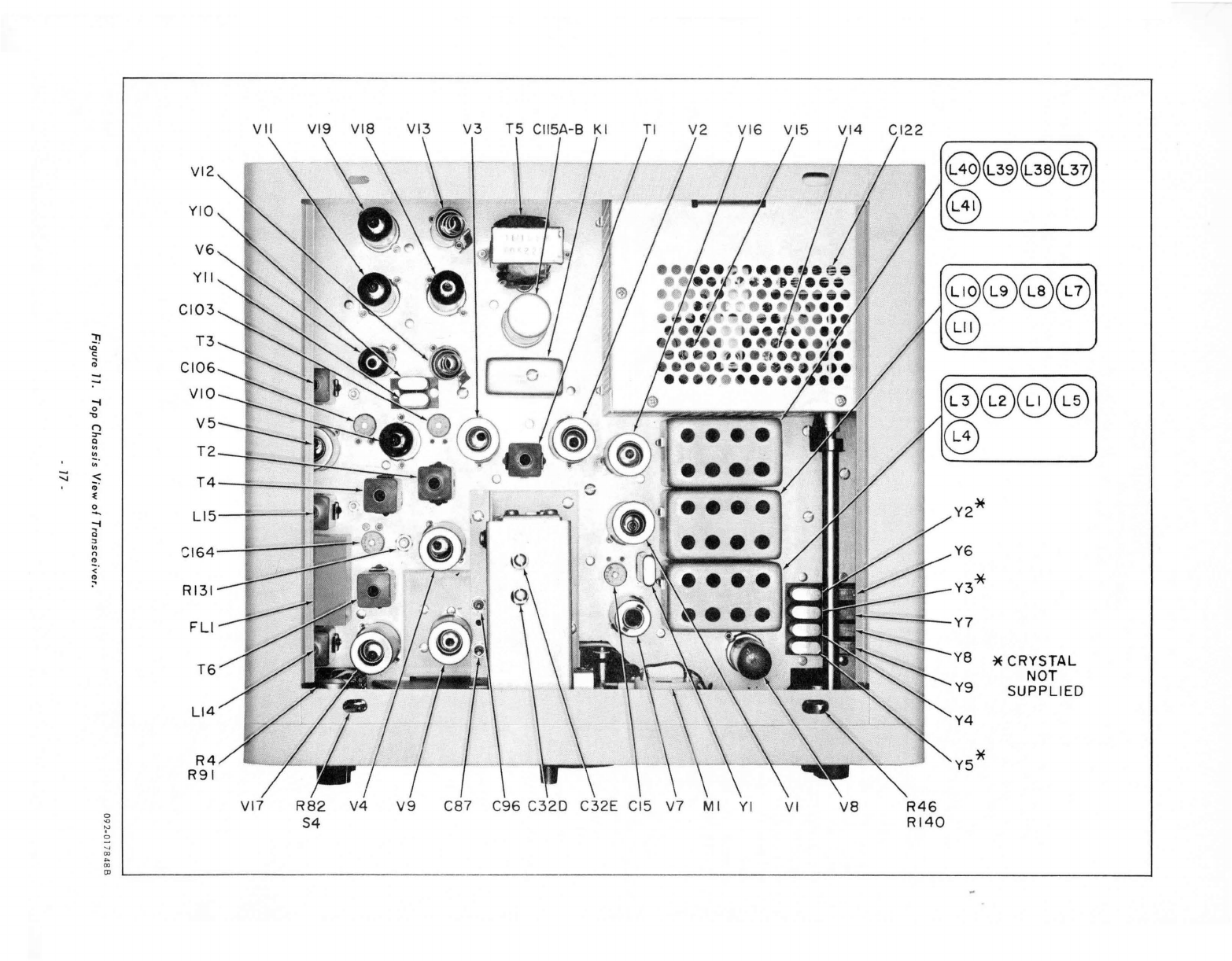
VI
I
VI9
VI3
V3
T5 C
II
5A
-B
KI
TI
V2
VI
6 V
I5
VI4 CI
22
VI2
0@@@
YIO
0
V6
YII
@@@@
CI03
@)
!I
T3
'"
c:
;0
CI06
-
:-
VIO
-i
0
."
V5
I')
:r
Q
'"
T2
'"
'"
::::;
< T4
;;
"
'"
Y2*
0
"""
Ll5
-i
i3
"
Y6
'"
CI
64
n
..
<" Y3*
..
RI31
FLI
Y7
YB
*
CRYSTAL
T6
NOT
SUPPLIED
Ll4
R4
R91
VI7
R82
V4
V9
C87 C
96
C32D C3
2E
CI5
V7
MI
YI
VI
va
R46
S4
RI40
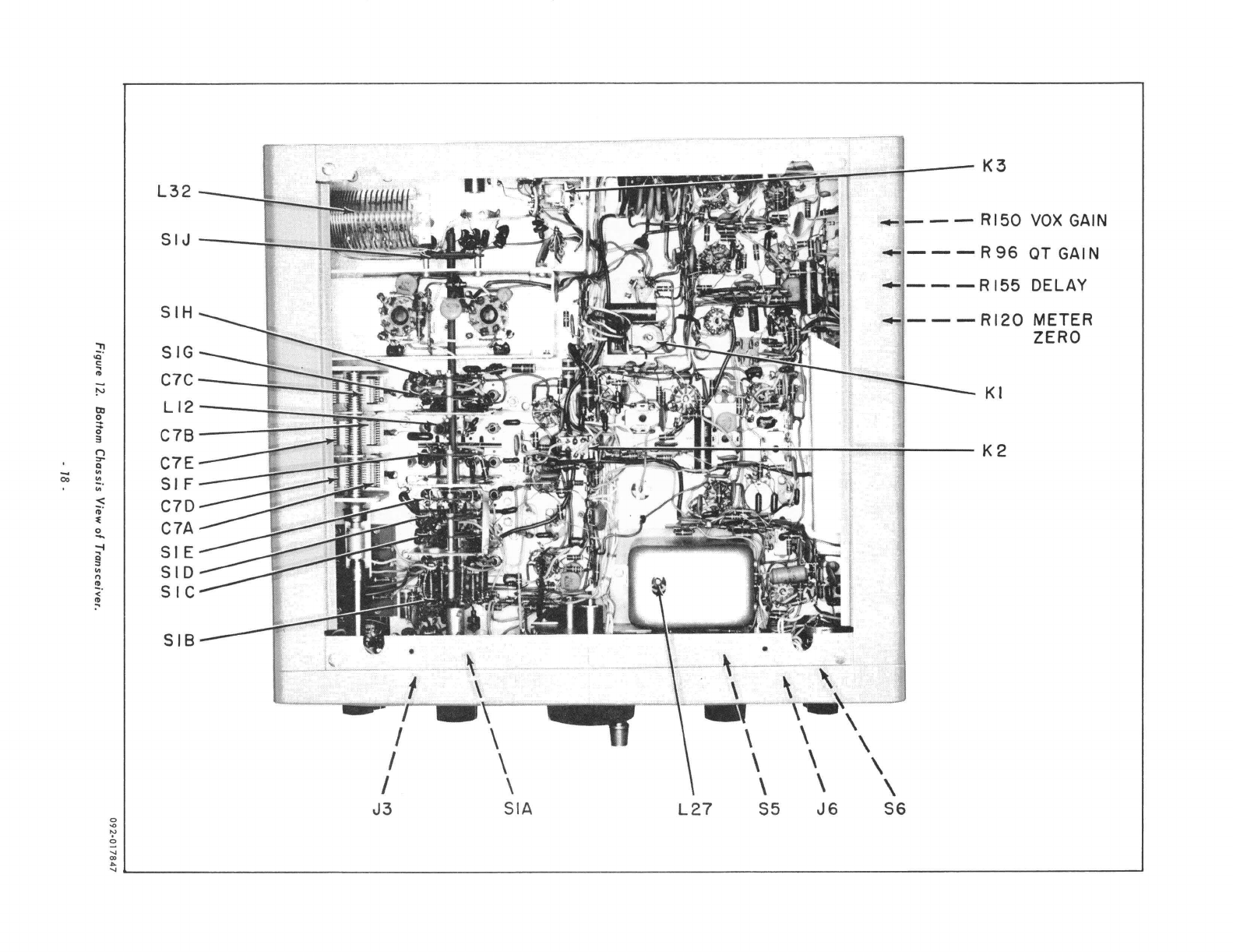
L32
SIJ--
~
__
SIH
"
SIG
.0'
!;
..
C7C
-=-
tv
til
LI2
~
0-
C7B
3
t")
C7E
""
Q
0;;
'"
~.
SIF
'"
-<
C7D
ii'
~
C7A
0
-.
-f
SIE
g
'"
SID
n
~
.
SIC
<
~
SIB
J3
SIA
L27
S5
\
\
\
J6
\ \ \ \
S6
K3
- -
RI50
VOX
GAIN
---R96
QTGAIN
- - R
155
DELAY
- - -
RI20
METER
ZERO
KI
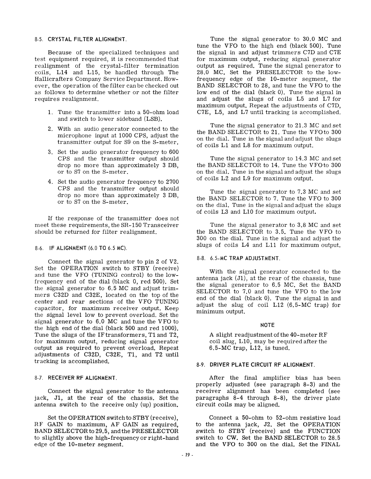
8-5.
CRYSTAL
FILTER
ALIGNMENT.
Because
of
the
specialized
techniques
and
test
equipment
required,
it
is
recommended
that
realignment
of
the
crystal-filter
termination
coils,
L14 and L15,
be
handled
through
The
Hallicrafters
Company
Service
Department.
How-
ever,
the
operation
of
the
filter
can
be
checked
out
as
follows
to
determine
whether
or
not
the
filter
requires
realignment.
1. Tune
the
transmitter
into
a
50-ohm
load
and
switch
to
lower
sideband
(LSB).
2. With an audio
generator
connected
to
the
microphone
input
at
1000
CPS,
adjust
the
transmitter
output
for
S9
on
the
S-meter.
3.
Set
the
audio
generator
frequency
to
600
CPS
and
the
transmitter
output
should
drop
no
more
than
approximately
3 DB,
or
to
S7
on
the
S-meter.
4.
Set
the
audio
generator
frequency
to
2700
CPS
and
the
transmitter
output
should
drop
no
more
than
approximately
3 DB,
or
to
S7
on
the
S-meter.
If
the
response
of
the
transmitter
does
not
meet
these
requirements,
the
SR-150
Transceiver
should
be
returned
for
filter
realignment.
8-6.
IF
ALIGNMENT
(6.0
TO
6.5
MC).
Connect
the
signal
generator
to
pin
2
of
V2.
Set
the
OPERATION
switch
to
STBY
(receive)
and
tune
the
VFO (TUNING
control)
to
the
low-
frequency
end
of
the
dial
(black
0,
red
500).
Set
the
Signal
generator
to
6.5
MC
and
adjust
trim-
mers
C32D
and
C32E,
located
on
the
top
of
the
center
and
rear
sections
of
the
VFO
TUNING
capacitor,
for
maximum
receiver
output.
Keep
the
signal
level
low
to
prevent
overload.
Set
the
Signal
generator
to
6.0
MC
and
tune
the
VFO
to
the
high
end
of
the
dial
(black
500
and
red
1000).
Tune
the
slugs
of
the
IFtransformers,
T1
and
T2,
for
maximum
output,
reducing
Signal
generator
output
as
required
to
prevent
overload.
Repeat
adjustments
of
C32D, C32E,
T1,
and
T2
until
tracking
is
accomplished.
8-7.
RECEIVER
RF
ALIGNMENT.
Connect
the
signal
generator
to
the
antenna
jack,
J1,
at
the
rear
of
the
chassis.
Set
the
antenna
switch
to
the
receive
only (up)
position.
Set
the
OPERATION
switch
to
STBY
(receive),
RF
GAIN
to
maximum,
AF
GAIN
as
reqUired,
BAND
SELECTOR
to
29.5,
and
the
PRESELECTOR
to
slightly
above
the
high-frequency
or
right-hand
edge
of
the
10-meter
segment.
-
19
-
Tune
the
signal
generator
to
30.0
MC
and
tune
the
VFO
to
the
high
end
(black
500). Tune
the
signal
in and
adjust
trimmers
C7D and C7E
for
maximum
output,
reducing
Signal
generator
output
as
required.
Tune
the
signal
generator
to
28.0 MC.
Set
the
PRESELECTOR
to
the
low-
frequency
edge
of
the
10-meter
segment,
the
BAND
SELECTOR
to
28,
and
tune
the
VFO to
the
low
end
of
the
dial
(black
0).
Tune
the
signal
in
and
adjust
the
slugs
of
coils
L5
and L7
for
maximum
output.
Repeat
the
adjustments
of
C7D,
C7E,
L5,
and
L7
until
tracking
is
accomplished.
Tune
the
Signal
generator
to 21.3 MC
and
set
the
BAND
SELECTOR
to
21. Tune
the
VFOto
300
on
the
dial.
Tune in
the
signal
and
adjust
the
slugs
of
coils
L1
and
L8
for
maximum
output.
Tune
the
signal
generator
to
14.3
MC and
set
the
BAND
SELECTOR
to
14. Tune
the
VFOto
300
on
the
dial.
Tune
in
the
signal
and
adjust
the
slugs
of
coils
L2 and L9
for
maximum
output.
Tune
the
signal
generator
to
7.3 MC
and
set
the
BAND
SELECTOR
to
7. Tune
the
VFO to 300
on
the
dial.
Tune in
the
signal
and
adjust
the
slugs
of
coils
L3
and
LIO
for
maximum
output.
Tune
the
Signal
generator
to
3.8
MC
and
set
the
BAND
SELECTOR
to
3.5. Tune
the
VFO
to
300 on
the
dial.
Tune
in
the
signal
and
adjust
the
slugs
of
coils
L4
and
Lll
for
maximum
output.
8-8.
6.S-MC
TRAP
ADJUSTMENT.
With
the
Signal
generator
connected
to
the
antenna
jack
(J1),
at
the
rear
of
the
chassis,
tune
the
signal
generator
to
6.5 MC.
Set
the
BAND
SELECTOR
to
7.0
and
tune
the
VFO to
the
low
end
of
the
dial
(black
0).
Tune
the
signal
in
and
adjust
the
slug
of
coil
LI2
(6.5-MC
trap)
for
minimum
output.
NOTE
A
slight
readjustment
of
the
40-meter
RF
coil
slug,
LIO,
may
be
required
after
the
6.5-MC
trap,
L12,
is
tuned.
8-9.
DRIVER
PLATE
CIRCUIT
RF
ALIGNMENT.
After
the
final
amplifier
bias
has
been
properly
adjusted
(see
paragraph
8-3)
and
the
receiver
alignment
has
been
completed
(see
paragraphs
8-4
through
8-8),
the
driver
plate
circuit
coils
may
be
aligned.
Connect
a
50-ohm
to
52-ohm
resistive
load
to
the
antenna
jack,
J2.
Set
the
OPERATION
switch
to
STBY
(receive)
and
the
FUNCTION
switch
to
CWo
Set
the
BAND
SELECTOR
to
28.5
and
the
VFO
to
300 on
the
dial.
Set
the
FINAL
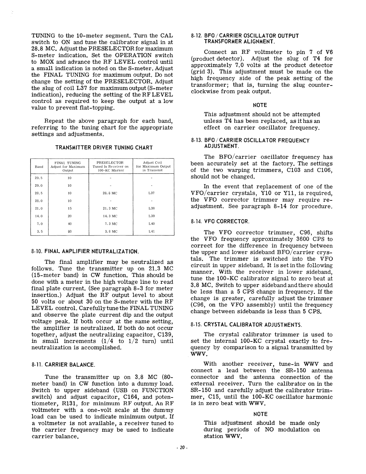
TUNING to the
10-meter
segment.
Turn
the CAL
switch
to
ON
and tune
the
calibrator
signal
in
at
28.8 MC. Adjust the
PRESELECTORfor
maximum
S-meter
indication. Set the OPERATION
switch
to
MOX
and advance
the
RF
LEVEL
control
until
a
small
indication
is
noted
on
the
S-meter.
Adjust
the FINAL TUNING
for
maximum
output.
Do
not
change the
setting
of
the
PRESELECTOR. Adjust
the
slug
of
coil
L37
for
maximum
output
(S-meter
indication),
reducing
the
setting
of the
RF
LEVEL
control
as
required
to
keep
the
output
at
a low
value
to
prevent
flat-topping.
Repeat
the
above
paragraph
for
each
band,
referring
to
the tuning
chart
for
the
appropriate
settings
and
adjustments.
TRANSMITTER
DRIVER
TUNING
CHART
FINAL TUNING
PRESELECTOR
Adjust
Coil
Band
Adjust
for
Maximum
Tuned
In
Receiver
on
for
Maximum
Output
Output
100-
KC
Marker
in
Transmit
29.5
10 --
29.0
10 --
28.5
10
28.8
MC L37
28.0
10 -
21.
0 15 21. 3 MC
L38
14.0
20
14.3
MC
L39
7.0
40
7.3
MC
L40
3.5
80
3.8
MC
L41
8-10.
FINAL
AMPLIFIER
NEUTRALIZATION.
The final
amplifier
may
be
neutralized
as
follows. Tune the
transmitter
up
on
21.3
MC
(15-meter
band) in
CW
function.
This
should
be
done with a
meter
in
the
high
voltage
line
to
read
final
plate
current.
(See
paragraph
8-3
for
meter
insertion.)
Adjust the
RF
output
level
to about
50
volts
or
about
30
on the
S-meter
with
the
RF
LEVEL
control.
Carefully
tune
the FINAL TUNING
and
observe
the
plate
current
dip and the output
voltage
peak.
If
both
occur
at
the
same
setting,
the
amplifier
is
neutralized.
If
both
do not
occur
together,
adjust
the
neutralizing
capacitor,
C139,
in
small
increments
(1/4
to
1/2
turn)
until
neutralization
is
accomplished.
8-11.
CARRIER
BALANCE.
Tune the
transmitter
up on 3.8
MC
(80-
meter
band)
in
CW
function into a dummy load.
Switch to
upper
sideband
(USB on FUNCTION
switch) and
adjust
capacitor,
C164, and
poten-
tiometer,
R131,
for
minimum
RF
output.
An
RF
voltmeter
with a
one-volt
scale
at
the
dummy
load
can
be
used
to
indicate
minimum
output.
If
a
voltmeter
is
not
available,
a
receiver
tuned to
the
carrier
frequency
may
be
used
to
indicate
carrier
balance.
-
20-
8-12.
BFO
/
CARRIER
OSCILLATOR
OUTPUT
TRANSFORMER
ALIGNMENT.
Connect an
RF
voltmeter
to
pin
7 of
V6
(product
detector).
Adjust
the
slug
of T4
for
approximately
7.0
volts
at
the
product
detector
(grid
3).
This
adjustment
must
be
made
on the
high
frequency
side
of
the
peak
setting
of the
transformer;
that
is,
turning
the
slug
counter-
clockwise
from
peak
output.
NOTE
This
adjustment
should
not
be
attempted
unless
T4
has
been
replaced,
as
it
has
an
effect
on
carrier
oscillator
frequency.
8-13.
BFO
/
CARRIER
OSCILLATOR
FREQUENCY
ADJUSTMENT.
The
BFO/
carrier
oscillator
frequency
has
been
accurately
set
at
the
factory.
The
settings
of the two
warping
trimmers,
C103 and C106,
should
not
be
changed.
In
the
event
that
replacement
of one
of
the
VFO/carrier
crystals,
Y10
or
Yll,
is
required,
the VFO
corrector
trimmer
may
require
re-
adjustment.
See
paragraph
8-14
for
procedure.
8-14.
VFO
CORRECTOR.
The
VFO
corrector
trimmer,
C96,
shifts
the VFO
frequency
approximately
3600 CPS to
correct
for
the
difference
in
frequency
between
the
upper
and
lower
sideband
BFO/
carrier
crys-
tals.
The
trimmer
is
switched
into the VFO
circuit
in
upper
sideband.
It
is
set
in
the
following
manner.
With the
receiver
in
lower
Sideband,
tune
the
100-KC
calibrator
Signal
to
zero
beat
at
3.8 MC. Switch to
upper
sideband
and
there
should
be
less
than
a 5 CPS change in
frequency.
If
the
change
is
greater,
carefully
adjust
the
trimmer
(C96,
on
the VFO
assembly)
until
the
frequency
change
between
sidebands
is
less
than
5 CPS.
8-15.
CRYSTAL
CALIBRATOR
ADJUSTMENTS.
The
crystal
calibrator
trimmer
is
used
to
set
the
internal
100-KC
crystal
exactly
to
fre-
quency by
comparison
to
a
signal
transmitted
by
WWV.
With
another
receiver,
tune-in
WWV
and
connect
a
lead
between
the
SR-150 antenna
connector
and the
antenna
connection
of
the
external
receiver.
Turn
the
calibrator
on
in
the
SR-150 and
carefully
adjust
the
calibrator
trim-
mer,
C15,
until
the 100-KC
oscillator
harmonic
is
in
zero
beat
with
WWV.
NOTE
This
adjustment
should
be
made
only
during
periods
of
NO
modulation on
station
WWV.
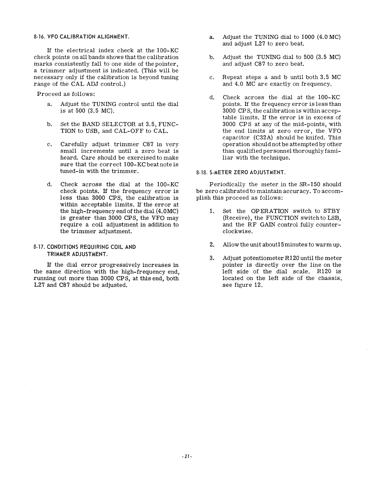
8-16.
VFO
CALIBRATION
ALIGNMENT.
If
the
electrical
index
check
at
the
100-KC
check
points
on
all
bands
shows
that
the
calibration
marks
consistently
fall
to
one
side
of
the
pointer,
a
trimmer
adjustment
is
indicated.
(This
will
be
necessary
only
if
the
calibration
is
beyond
tuning
range
of
the
CAL ADJ
control.)
Proceed
as
follows:
a.
Adjust
the
TUNING
control
until
the
dial
is
at
500 (3.5 MC).
b. Set
the
BAND SELECTOR
at
3.5,
FUNC-
TION to USB, and
CAL-OFF
to CAL.
c.
Carefully
adjust
trimmer
C87
in
very
small
increments
until
a
zero
beat
is
heard.
Care
should
be
exercised
to
make
sure
that
the
correct
100-KCbeatnoteis
tuned-in
with
the
trimmer.
d. Check
across
the
dial
at
the
100-
KC
check
points.
If
the
frequency
error
is
less
than
3000 CPS,
the
calibration
is
within
acceptable
limits.
If
the
error
at
the
high-frequency
end
ofthe
dial
(4.0MC)
is
greater
than
3000 CPS,
the
VFO
may
require
a
coil
adjustment
in
addition
to
the
trimmer
adjustment.
8-17.
CONDITIONS
REQUIRING
COIL
AND
TRIMMER
ADJUSTMENT.
If
the
dial
error
progressively
increases
in
the
same
direction
with
the
high-frequency
end,
running
out
more
than
3000 CPS,
at
this
end,
both
L27 and C87
should
be
adjusted.
-21-
a.
Adjust
the
TUNING
dial
to 1000 (4.0
MC)
and
adjust
L27 to
zero
beat.
b.
Adjust
the
TUNING
dial
to 500 (3.5
MC)
a!1d
adjust
C87 to
zero
beat.
c.
Repeat
steps
a and b
until
both
3.5
MC
and 4.0
MC
are
exactly
on
frequency.
d.
Check
across
the
dial
at
the
100-KC
points.
If
the
frequency
error
is
less
than
3000 CP
S,
the
calibration
is
within
accep-
table
limits.
If
the
error
is
in
excess
of
3000
CPS
at
any of
the
mid-points,
with
the
end
limits
at
zero
error,
the
VFO
capacitor
(C32A)
should
be
knifed.
This
operation
should
not
be
attempted
by
other
than
qualified
personnel
thoroughly
fami-
liar
with
the
technique.
8-18.
S-METER
ZERO
ADJUSTMENT.
Periodically
the
meter
in
the
SR-150
should
be
zero
calibrated
to
maintain
accuracy.
To
accom-
plish
this
proceed
as
follows:
1. Set
the
OP ERATION
switch
to STBY
(Receive),
the
FUNCTION
switch
to LSB,
and
the
RF
GAIN
control
fully
counter-
clockwise.
2. Allow
the
unit
about15minutes
to
warm
up.
3.
Adjust
potentiometer
R120
until
the
meter
pointer
is
directly
over
the
line
on
the
left
side
of
the
dial
scale.
R120
is
located
on
the
left
Side of
the
chassis,
see
figure
12.
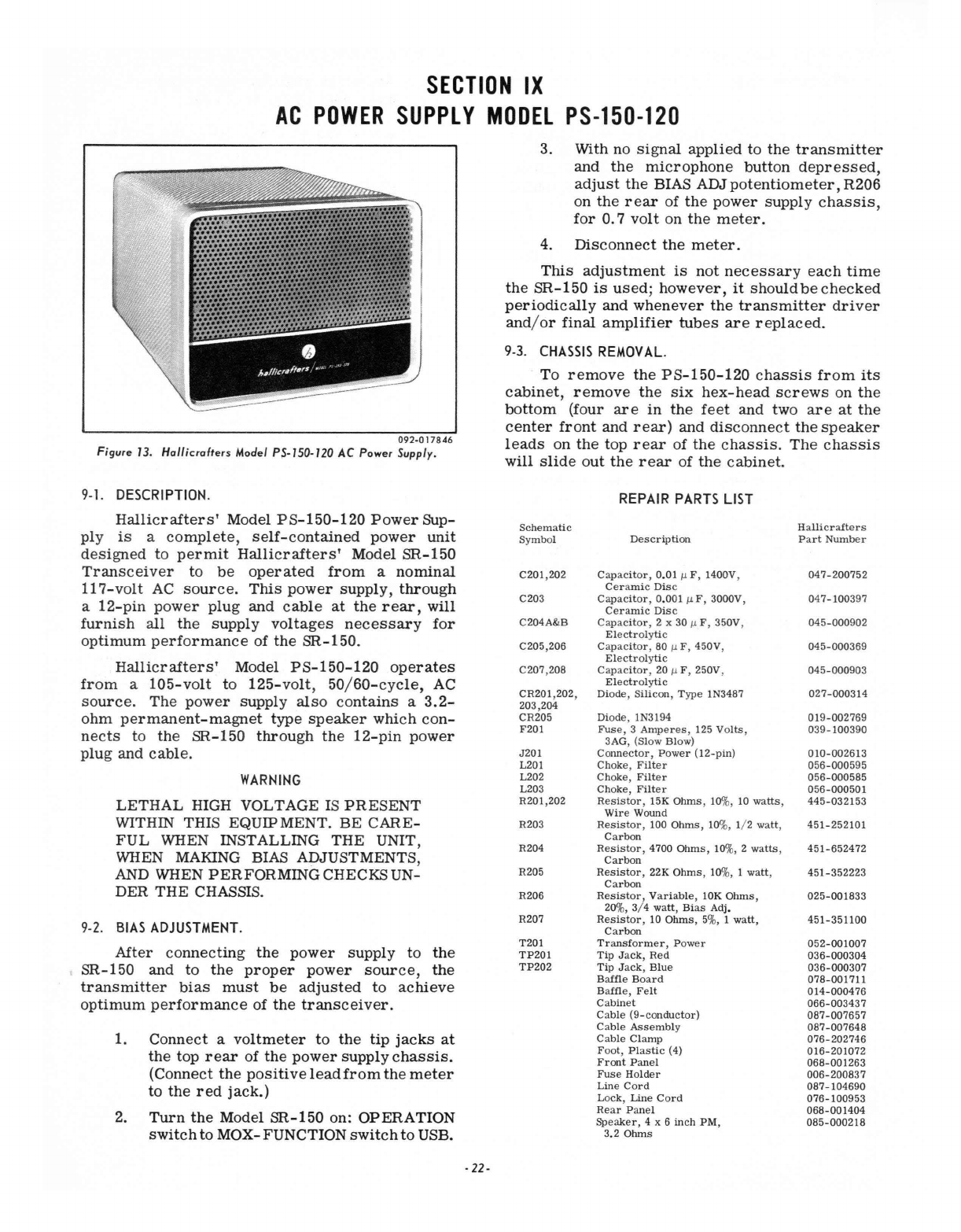
SECTION
IX
AC
POWER
SUPPLY
MODEL
PS-150-120
092·017846
Figure
13.
Hol/ieroffers
Model P$·150·120
AC
Power Supply.
9·1.
DESCRIPTION.
Hallicrafters'
Model
PS-150-120
Power
Sup-
ply
is
a
complete,
self-contained
power
unit
designed
to
permit
Hallicrafters'
Model
SR-150
Transceiver
to
be
operated
from
a
nominal
117-volt
AC
source.
This
power
supply,
through
a
12-pin
power
plug
and
cable
at
the
rear,
will
furnish
all
the
supply
voltages
necessary
for
optimum
performance
of
the
SR-150.
Hallicrafters'
Model
PS-150-120
operates
from
a
105-volt
to
125-volt,
50
/
60-cycle,
AC
source.
The
power
supply
also
contains
a
3.2-
ohm
permanent-magnet
type
speaker
which
con-
nects
to
the
SR-150
through
the
12-pin
power
plug
and
cable.
WARNING
LETHAL
HIGH VOLTAGE
IS
PRESENT
WITHIN THIS EQUIP MENT.
BE
CARE-
FUL
WHEN INSTALLING
THE
UNIT,
MIEN
MAKING BIAS ADJUSTMENTS,
AND
MIEN
PERFORMING
CHECKS UN-
DER
THE
CHASSIS.
9·2
.
BIAS
ADJUSTMENT
.
After
connecting
the
power
supply
to
the
SR-150 and
to
the
proper
power
source,
the
transmitter
bias
must
be
adjusted
to
achieve
optimum
performance
of
the
transceiver.
1.
Connect
a
voltmeter
to
the
tip
jacks
at
the
top
rear
of
the
power
supply
chassis.
(Connect
the
positive
lead
from
the
meter
to
the
red
jack.)
2.
Turn
the
Model
SR-150
on: OPERATION
switch
to
MOX- FUNCTION
switch
to
USB.
·22·
3. With no Signal
applied
to
the
transmitter
and
the
microphone
button
depressed,
adjust
the
BIAS ADJ
potentiometer,
R206
on
the
rear
of
the
power
supply
chassis,
for
0.7
volt
on
the
meter.
4.
Disconnect
the
meter.
This
adjustment
is
not
necessary
each
time
the
SR-150
is
used;
however,
it
should
be
checked
periodically
and
whenever
the
transmitter
driver
and
/o
r
final
amplifier
tubes
are
replaced.
9·3.
CHASSIS
REMOVAL.
To
remove
the
PS-150-120
chassis
from
its
cabinet,
remove
the
six
hex-head
screws
on
the
bottom
(four
are
in
the
feet
and two
are
at
the
center
front
and
rear)
and
disconnect
the
speaker
leads
on
the
top
rear
of
the
chassis.
The
chassis
will
slide
out
the
rear
of
the
cabinet.
REPAIR
PARTS
LIST
Schematic
Ha
llicraft
e
rs
Sy
mb
ol
Description
Part
Number
C201 ,202
Capacitor,
0.01
fJ.
F , 1400V,
047-200752
Ceramic
Dis
c
C203 Ca
pacitor,
0.001
fJ.
F,
3000V,
047-100397
Ceramic
Dis
c
C204A&B
Capacitor,
2 x 30
fJ.
F, 350V,
045-000902
Electr
oly
ti
c
C205,206
Capacitor
,
80
fJ.
F ,
450V
,
045-00036
9
Electrolytic
C207,208
Capacitor,
20
fJ.
F,
250V, 045
-00090
3
Electrolytic
CR201,202,
Diode
,
Silicon,
T
ype
1N3487
027-000314
203,204
CR205
Diode
, 1N3194
019-002769
F201
Fuse,
3
Amperes
, 125
Volts,
039-100
390
3AG, (Sl
ow
Bl
ow)
J201
Connector,
Power
(l2-pin)
010·002613
L201
Choke
,
Filter
056-000595
L202
Choke,
Filter
056-000585
L203
Choke,
Filter
056-000501
R201 ,202 R
es
istor
, 15K
Ohms,
10%, 10
wa
tts
,
445-032153
Wir
e Wound
R203
Resistor
, 100
Ohms,
10%,
1/
2
watt,
451-252101
Carbon
R204 Re
sistor
, 4700
Ohms
, 10%, 2
watts,
451-652472
Carbon
R205
Resistor,
22K
Ohms,
10%, 1
watt,
451-352223
Carbon
R206
Resistor,
Variable,
10K
Ohms,
025-001833
20%, 3/ 4
watt,
Bi
as Adj.
R207
Resistor
, 10
Ohms
, 5
%,
1
watt,
451-351100
Carbon
T201
Transformer,
Power
052-001007
TP201
Tip
J
ack,
Red
036-000304
TP202
Tip
Jack
,
Blue
036-000307
Baffle
Board
078-001711
Baffle,
Felt
014-000476
Cabinet
066-003437
Ca
bl
e (9-
conductor)
087-007657
Cable
Assembl
y
087-007648
Cable
Clamp
076-202746
Fo
ot
,
Plastic
(4)
016-201072
Front
Panel
068-001263
Fuse
Holder
006-200837
Line
Cord
087-104690
Lock
,
Line
Cord
076-100953
Rear
Panel
068-001404
Speaker
, 4 x 6
inch
PM,
085-000218
3.2
Ohms
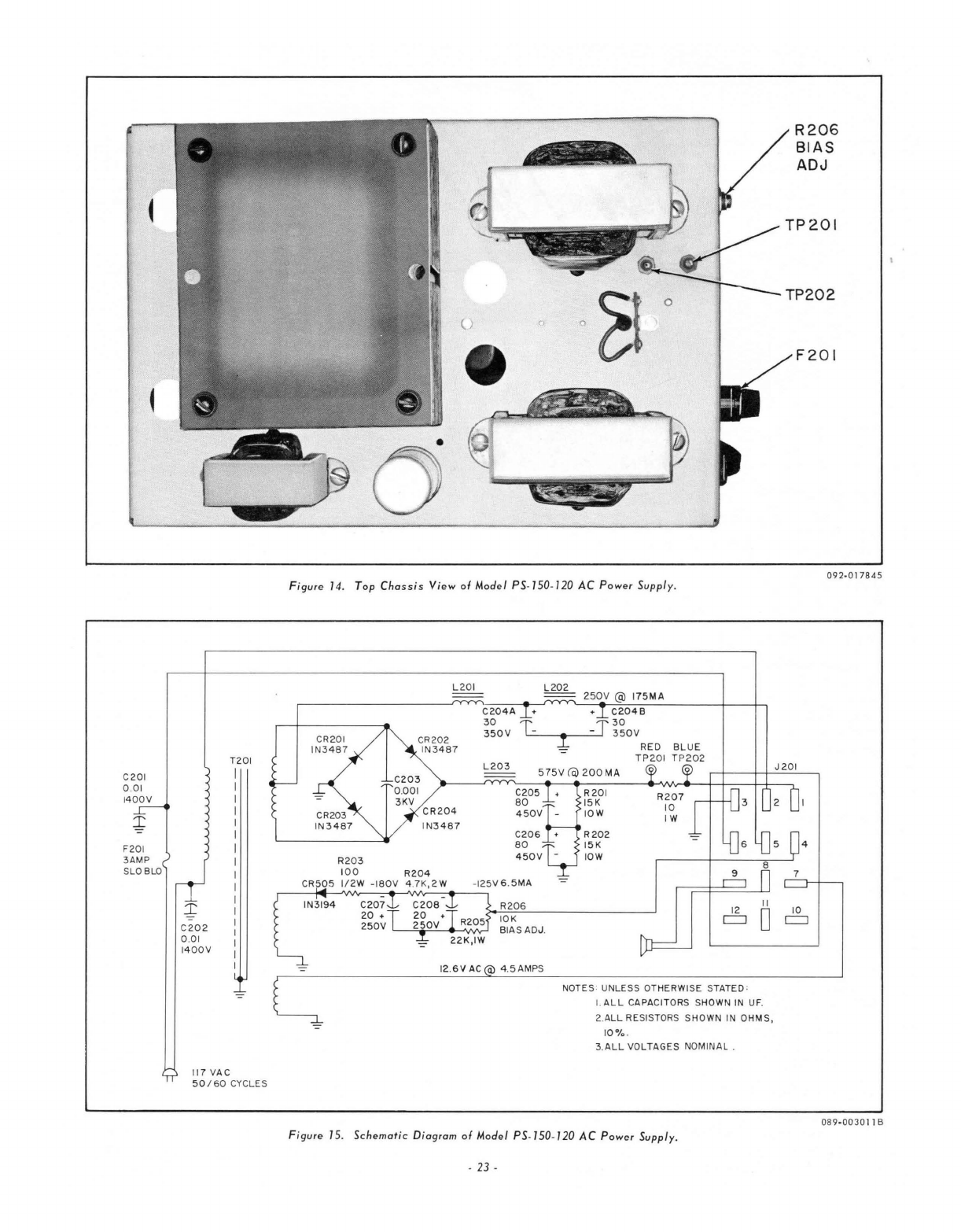
C201
0 .
01
1400V
F201
3AMP
S
LO
8LO
C202
0 .
01
1400V
117
VAC
T201
I
I
I
I
I
I
I
I
I
I
I
I
I
I
I
I
I
50
/
60
CYCLES
o
o o
Figure 14. Top
Chassis
View of
Mod
e l PS·
150·/20
AC
Power Suppl
y.
L201
C204
A
CR202
IN3487
30
T
350V
....
-
--1---'
RED
8LUE
TP2
0 1
TP202
R20 3
CR204
I
N3487
1
00
R204
L203
C205
80
450V
-
C20
6
80
CR50 S 1/2W
-180V
4.7K,
2W
·125V 6 .
5MA
IN3194
C207
20
+
250V
'---'=,;r=-:.....-
'VY'y-J
R206
10K
BIAS
AD
J.
12
.
6V
AC
4.5AMPS
II
80
NOTES : UNLESS OTHERWI
SE
STATED :
I.
ALL
CAPAC
ITORS S
HOW
N
IN
UFo
2.ALL RESISTORS S
HOWN
IN OHMS,
10%
.
3.
ALL
VO
LTAGES NOMINAL .
Figure IS . Schematic Diagram of Model PS·150·/20
AC
Power Supply .
.
23
·
R206
BIAS
ADJ
TP202
F201
4
10
c::::=:J
092·017845
089·0030
11
B
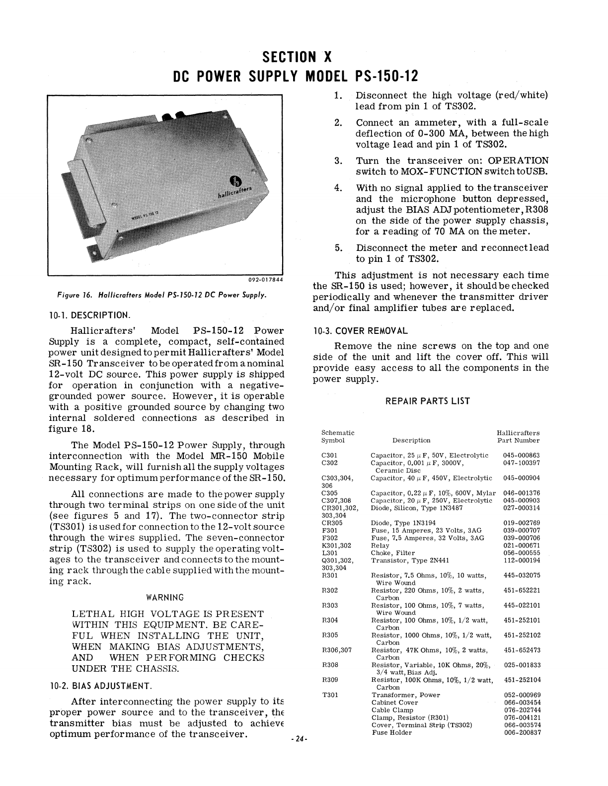
SECTION
X
DC
POWER
SUPPLY
MODEL
PS-150-12
092·017844
Figure
16.
Hal/icrafters
Model
PS·150·12
DC
Power Supply.
10·
1.
DESCRIPTION.
Hallicrafters'
Model
PS-150-12
Power
Supply
is
a
complete,
compact,
self-contained
power
unit
designed
to
permit
Hallicrafters'
Model
SR-150
Transceiver
to
be
operated
from
a
nominal
12-volt
DC
source.
This
power
supply
is
shipped
for
operation
in
conjunction
with
a
negative-
grounded
power
source.
However,
it
is
operable
with
a
positive
grounded
source
by
changing
two
internal
soldered
connections
as
described
in
figure
18.
The
Model
PS-150-12
Power
Supply,
through
interconnection
with
the
Model MR-150 Mobile
Mounting
Rack,
will
furnish
all
the
supply
voltages
necessary
for
optimum
performance
ofthe
SR-150.
All
connections
are
made
to
the
power
supply
through
two
terminal
strips
on
one
side
of
the
unit
(see
figures
5 and 17).
The
two-connector
strip
(TS301)
is
used
for
connection
to
the
12-volt
source
through
the
wires
supplied.
The
seven-connector
strip
(TS302)
is
used
to
supply
the
operating
volt-
ages
to
the
transceiver
and
connects
to
the
mount-
ing
rack
through
the
cable
supplied
with
the
mount-
ing
rack.
WARNING
LETHAL
HIGH
VOLTAGE
IS
PRESENT
WITHIN THIS EQUIPMENT.
BE
CARE-
FUL
WHEN INSTALLING THE UNIT,
WHEN MAKING BIAS ADJUSTMENTS,
AND WHEN
PERFORMING
CHECKS
UNDER THE CHASSIS.
10-2.
BIAS
ADJUSTMENT.
After
interconnecting
the
power
supply
to
its
proper
power
source
and
to
the
transceiver,
thE
transmitter
bias
must
be
adjusted
to achievE
optimum
performance
of
the
transceiver.
-
24-
1.
Disconnect
the
high
voltage
(red/white)
lead
from
pin
1 of TS302.
2.
Connect
an
ammeter,
with
a
full-scale
deflection
of
0-300
MA,
between
the
high
voltage
lead
and
pin
1
of
TS302.
3.
Turn
the
transceiver
on: OPERATION
switch
to
MOX-
FUNCTION
switch
to USB.
4. With no Signal
applied
to
the
transceiver
and
the
microphone
button
depressed,
adjust
the
BIAS ADJ
potentiometer,
R308
on
the
side
of
the
power
supply
chassis,
for
a
reading
of
70
MA
on
the
meter.
5.
Disconnect
the
meter
and
reconnectlead
to
pin
1 of TS302.
This
adjustment
is
not
necessary
each
time
the
SR-150
is
used;
however,
it
should
be
checked
periodically
and
whenever
the
transmitter
driver
and/or
final
amplifier
tubes
are
replaced.
10-3.
COVER
REMOVAL
Remove
the
nine
screws
on
the
top and one
side
of
the
unit
and
lift
the
cover
off.
This
will
provide
easy
access
to
all
the
components
in
the
power
supply.
REPAIR
PARTS
LIST
Schematic
Hallicrafters
Symbol
Description
Part
Number
C301
Capacitor,
25
/L
F,
50V,
Electrolytic
045-000863
C302
Capacitor,
0.001
/L
F,
3000V, 047-100397
Ceramic
Disc
C303,304,
Capacitor,
40
/L
F,
450V,
Electrolytic
045-000904
306
C305
Capacitor,
0.22/L
F,
10%,
600V,
Mylar
046-001376
C307,308
Capacitor,
20
/L
F,
250V,
Electrolytic
045-000903
CR301,302, Diode, Silicon, Type 1N3487 027-000314
303,304
CR305 Diode, Type 1N3194 019-002769
F301
Fuse,
15
Amperes,
23
Volts,
3AG 039-000707
F302
Fuse,
7.5
Amperes,
32
Volts,
3AG 039-000706
K301,302
Relay
021-000671
L301 Choke,
Filter
056-000555
Q301,302,
Transistor,
Type
2N441 112-000194
303,304
R301
Resistor,
7.5
Ohms,
10%,
10
watts,
445-032075
Wire
Wound
R302
Resistor,
220 Ohms,
10%,
2
watts,
451-652221
Carbon
R303
Resistor,
100 Ohms,
10%,
7
watts,
445-022101
Wire
Wound
R304
Resistor,
100 Ohms,
10%,
1/2
watt,
451-252101
Carbon
R305
Resistor,
1000
Ohms,
10%,
1/2
watt, 451-252102
Carbon
R306,307
Resistor,
47K
Ohms,
10%,
2
watts,
451-652473
Carbon
R308
Resistor,
Variable,
10K
Ohms,
20%,
3/4
watt,
Bias
Adj. 025-001833
R309
ReSistor,
lOOK
Ohms,
10%,
1/2
watt,
451-252104
Carbon
T301
Transformer,
Power
052-000969
Cabinet
Cover
066-003454
Cable
Clamp
076-202744
Clamp,
Resistor
(R301) 076-004121
Cover,
Terminal
Strip
(TS302) 066-003574
Fuse
Holder
006-200837
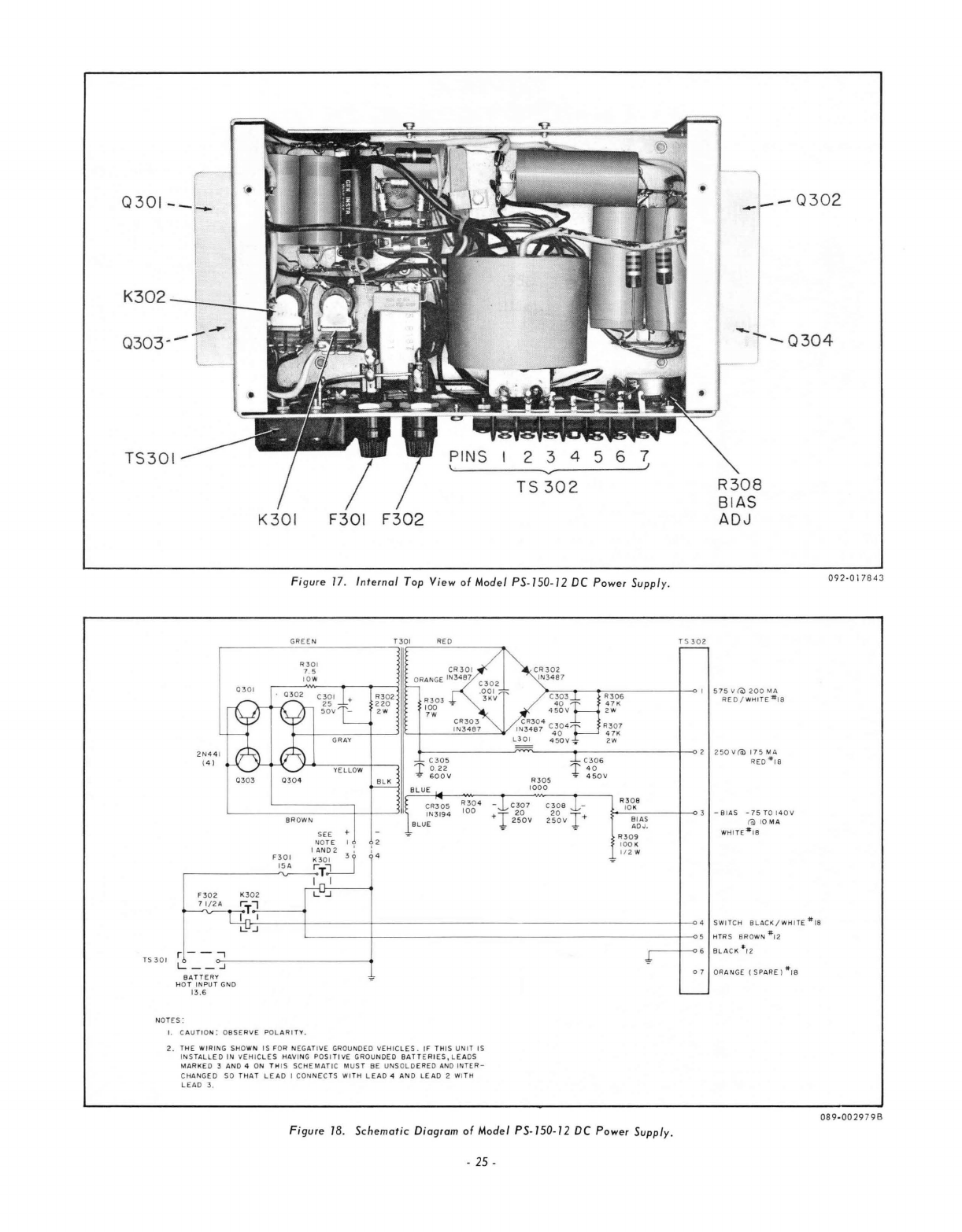
0301-_
-l
__
0302
- I
i
--
0303--
! -T
-0304
'---
TS301
K301 F301
F302
~-------------~----------
--~
TS
302
R308
BIAS
ADJ
Figure
17.
Internal Top
View
of Moclel PS·150·12 DC Power Supply.
GREE N
R301
7 .5
lO
W
1301
REO
15302
~
=
,...
-_
=.,..,..----
+-<>
I
575
\I
(Q)
200
MA
~~~6
REO/WHITE'j$"
18
2 W
R3
07
47K
2W
r-
-------~~--
--<r
------
-_+
-o
2
250
v(Q)
115
MQ,
C
R3
Q5
I
N3194
BLUE
R30
5
1000
C306
l'
:
~ov
RE O
-#IB
R
308
~
c.I
O
:..
K
_,--_-+-<>:3
_ BI
AS
-
75
TO
14 0
II
~b~~
fa) 10 M A
R309
WH
ITE - IS
10
01(
1/2
W
09 2-0 1
7843
LC
'fl-
..,-----j------+
--
---------------
--
------
-j-
-04
SWITCH
BLACK/
WH
I
TE
*'
18
L-
____
+
_________________________
I---<>5
HTRS BROWN
#'2
NOTES :
I.
C A
UTIO
N : O
BSERVE
POL
A
RIT
Y.
2.
THE W
IRING
SHOWN
IS
FOR
NEGATIVE
GROUNDED
VEHIC
LE
S .
IF
TH
IS
UNIT
IS
INST
A
LLED
IN
vEH
IC
LE
S HAV ING POSI
TI
vE
GROU NDED BAT T E
RI
ES , L
EA
DS
MARKED
3
AND
4 ON
TH
IS
SCHEMATIC
MU
ST
8E
UNSOLD
ERED AND
INTER-
C
HANGED
SO
THA
T
LEAD
I CON NEC TS
WITH
LEAD
4 A N D
LEAD
2
WITH
LEAD
3 .
r---/--o
6
8L
ACK *, 2
07
O
RANGE
(S
PA
RE
)
*rB
Figure
18.
Schematic
Diagr
am
of
Moclel
PS·150·12 DC Power Supply.
-2
5 -
08 9
-0029
79
B

SECTION
XI
MOBILE
MOUNTING
RACK
MODEL
MR-150
11-1.
DESCRIPTION.
Hallicrafters'
Model MR-150 Mobile Mounting
Rack
is
a
sturdy,
compact
unit
designed
to
facili-
tate
mobile
installation
of
the
Model SR-150
Transceiver.
This
mounting
rack,
with mounting
bracket
and
straps
supplied,
permits
transmission
hump,
floor,
and/or
under
dash
mounting
of
the
transceiver
(see
figures
4 and 5).
This
rack
is
equipped with a
cable
for
con-
nection
to
the
PS-150-12
Power
Supply,
an
audio
connector
brought
out
to
the
side
for
connection
to
speaker,
and
provisions
for
a
direct
connection
to a
suitable
antenna.
The
side
panels
of the mounting
rack
fit
snuggly
against
the
transceiver
for
a
secure
installation.
Wing
screws
are
supplied
to
attach
the
transceiver
to
these
side
panels.
092-017932
Figure
19.
Hallicrafters
Model MR-1S0 Mobile Mounting
Rack.
Details
for
installing
this
equipment
in a
ve-
hicle
are
described
in
paragraph
3-4
and in
figures
4 and 5 of
this
handbook.
J
401
n t}-
REO/WHITE
·,8
~
~
10 7 4 I
RED'#'8
=
r--=
-c::::J
......
1/ B 5 2
0 9 J
I:l$l
t::a
12 6 3
WHITE
#,8
J402
~
V
BLACK
/
WHITE
'#'B
J
BROWN
·,2
J403
NOTE
I
BLACK
·,2
cp
/ \
0-
- - - -
-1
1
ORANGE'#'8
-=-
-
NOTES;
THE
AREA
DOTTED
IN
SHOWS
WIRING
NECESSARY
IF
A
COAXIAL
CONNECTOR
IS
AFFIXED
TO
THE
SIDE
OF
THE
MOUNTING
RACK
AND
INTERNAL
COAXIAL
CABLE
ADDED
BETWEEN
THIS
CONNECTOR
AND
J403.
IF
DESIRED.
THE
ANTENNA
MAY BE
CONNECTED
DIRECTLY
TO
J403.
,....,
I
2
3
4
S~
6
7
U
TO TS
S02
ON
PS-150-12.PINS
575V
AS
MARKED.
(SEE
FIGURE
IT)
2S0V
-9SV
BIAS
SWITCH
FILAMENTS
GROUND
SPARE
Figure
20.
Schematic
Diagram
of
Model MR-1S0 Mobile Mounting
Rack.
089-003331
B
-
26-
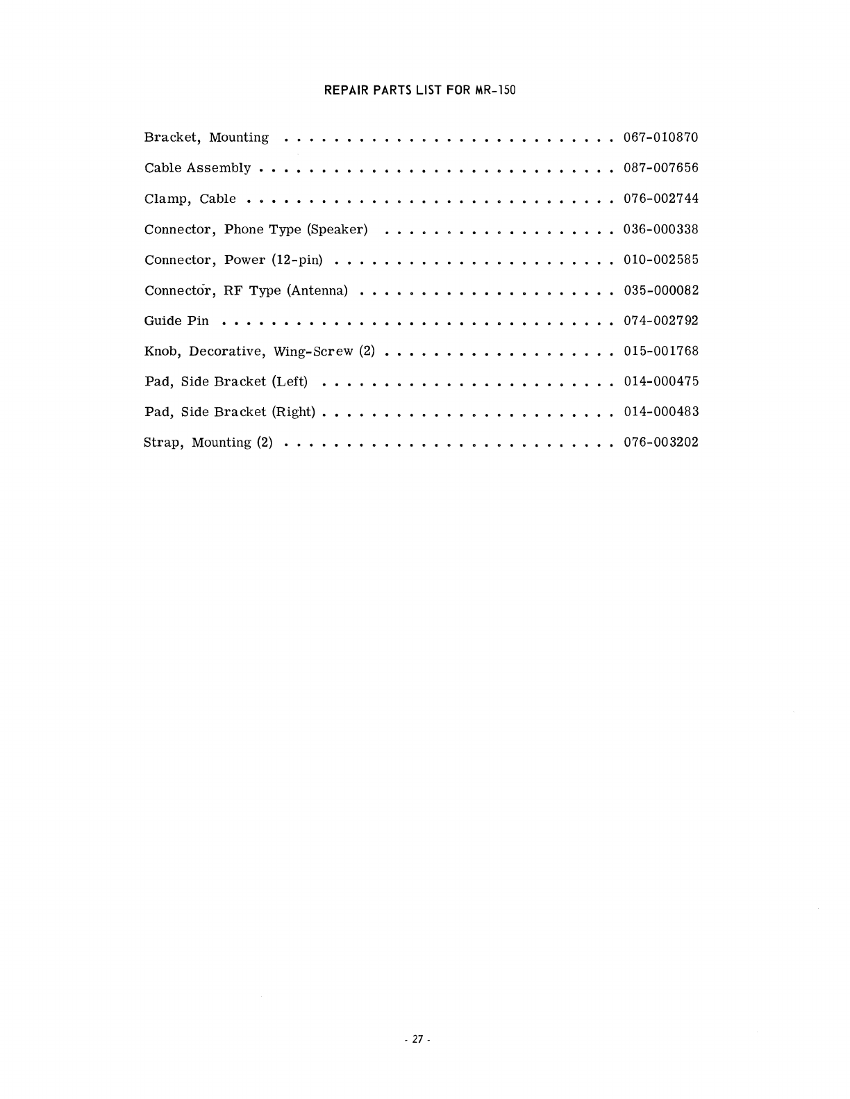
REPAIR
PARTS
LIST
FOR
MR-1SO
Bracket,
Mounting
Cable
Assembly
Clamp,
Cable
•
Connector,
Phone
Type
(Speaker)
Connector,
Power
(12-pin) . • •
Connector,
RF
Type
(Antenna)
Guide
Pin
...........
.
Knob,
Decorative,
Wing-Screw
(2)
Pad,
Side
Bracket
(Left) •
Pad,
Side
Bracket
(Right) • •
Strap,
Mounting
(2)
• • • • •
-
27-
067-010870
087-007656
076-002744
036-000338
010-002585
035-000082
074-002792
015-001768
014-000475
014-000483
076-003202

'.
NOTES:
-
28-
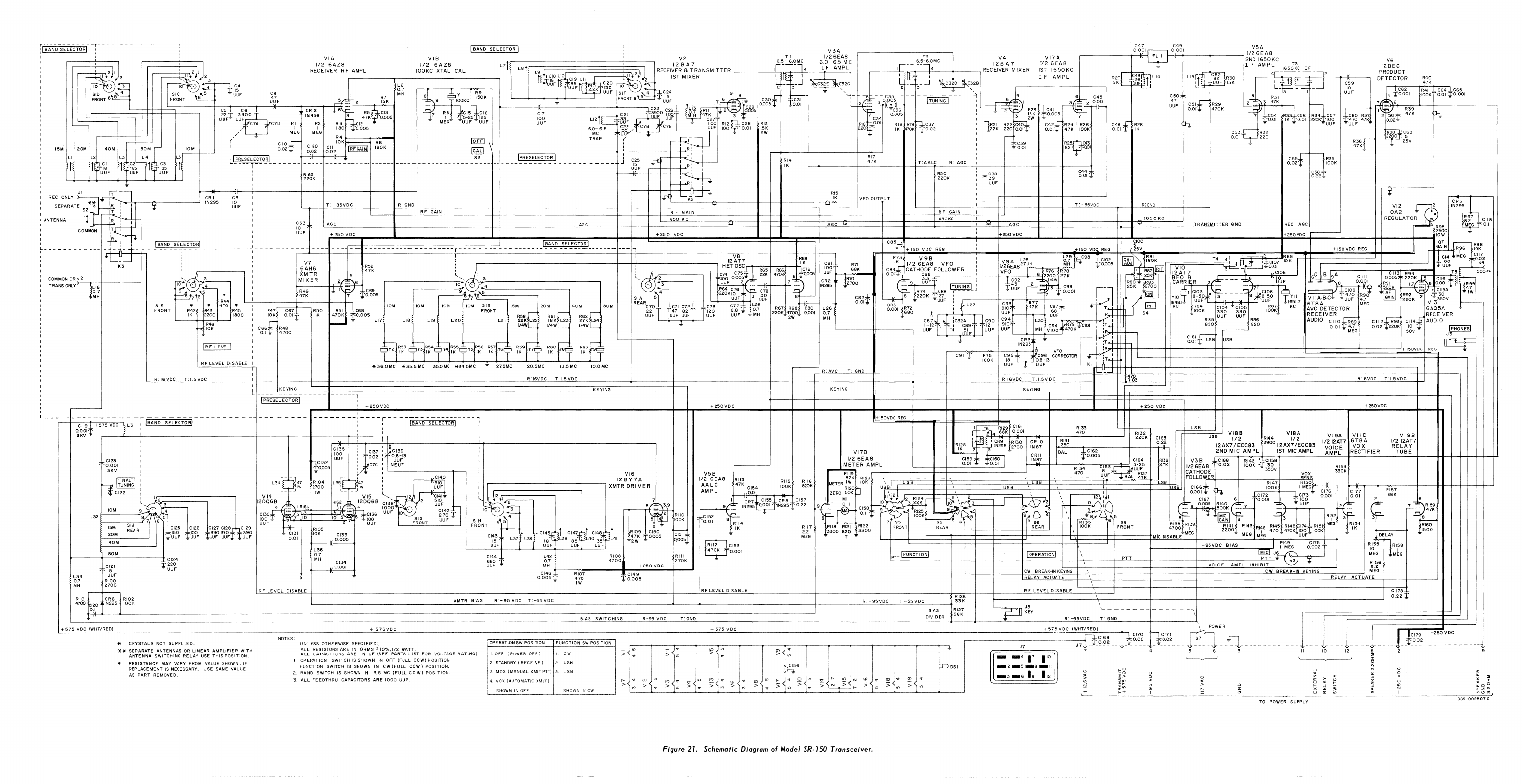
15M
Ll
---r---
,
--
---
-----
--
-
---
__
u
_________
---
___
n_
- -
--
-
------
- -
-(~;NO
S~~~C~~R
C--
-
--
-
--
-------
--
-
---l
VIA
1/2
6AZ8
RECEIVER
R F
AMPL
VIB
1/2
6AZ8
100KC
XTAL
CAL
V3A
V2
TI
J/26EA8
T2
V4
VI7A
C47
C49
Ll5 1
'j
82
R30
V6
12
BE6
PRODUCT
DETECTOR
R40
47K
~
:
,'~
~~U2
,----T-,",,"
,'12J)2
3
L711:LB;1~~L~9~~~CC';B~L~10~C~'9~L~"
~~~~~~~~,
~~
\"2~J~IJ:j'2l
RECEI~~R~AiRRANSMITTER
,-
___
~,[~16-,·'"-~~~~l4-
$6I~-
~~~pML
C
r;c~-~+-~-_~~_6t=1~~,-M-C$--+--:---'
RECIE~:E~
~
IXER
~~;
~iS~~C
10
3 I
10
- I
~~C4
.-------.-L-6--------------.
t~~Fti\CB51~RIOI
C20
10
:,-
h,
~
-
3-
J C32E C,'2C
'2
--3--.J
C320
C,32B
~,-----
SID
4
F~lgNT
~
l~~F
~~
R7
~.~
cbY'
~~15:90K"1UUFI)J..~1~J~~5F
SIF
;~L;;kC24
9 -
',-
". ,
l
J~F~R~0~NT~6~5~~~tM1~~==l-11B~~~~~U:U~F~~l~~~-~5
__
~_2'___+_~15-K___i
~9
T'OOKC
~
FRONT6\i'::':::
'I'J,';F
7
6.,c,~:
__
81~
o~~~f
Tg~:
-
~-~~O~~
-
-1;u;N~I-----:
6
:=;
I
[1;
46~2~~
C5
I
C6
I CRI2
~
6\
;:;
;~;
:1
f.~
~----1(_---------+__--~C23
C26
~l3
Rll
IL
2 '
8665
-
--
~c'~6
I
..
2 - R23
C41
...: -=-[ "
C50
47
UUF
r!~~~52~
I I UUF
15K
L_
C51~
R29
0.011'
470K
C59
10
UUF
l;;
*~62
rR41
~C6~*~65
5
't
o.
001
lOOK
['0.01
--r
0.
001
Itf~6
;
*' *'
~
-
'I='-
R5 CI3
R6
CI5 C
16
CI7
3900
07
I
~
~
15
K
000'
'-'--
_ C7A C7D
RI
R2
R3
:
~~12
MEG-
""UUF
""UUF
UUF
Ll2lL----..:: UUF -
100
RI2
C28
RI3
RIG
0.01
Ria
RI9
h
C37
I
~~2[
R22~
C42;:[
R24 R26
U
2
U
2
Fl'
u~9BOO
IN456
h.
47K
0.005
7 I
5-25T125
100
tr---:
gj'
~
0~~
M H
47t27
-3
~
7
C34
0.005
I - 3 2W
1'....
7
[ I
[80
l'O.005
6.0-6.5
ro1,2"
C7B
C7E
UUf
[00
001
[5K
220
[K
d7OK:
T~.02
I =22K
2200.0[1'
O.Olt
41K
lOOK
MEG
MEG
MC
Ul!F"
-n:tJ,..
2W
,,~
- I
C46,
~
R28
0.01 r
IK
I C60 R37
t~70
47K
""UUF
.".
20M
40M
L2
1
~~~
~IUF
--
BOM
L3
L4
l'
¥~5r
lLf
~3~
It,
UUF
1
UUF
10M
L~
CR
I
IN295
(/.".
~
~
~O~
t---------< R6
[Q£II
\ TRAP ( T I - C39
l
g~~1"
gl~~
gg2
IRFGAINI ISOK
[@
1 I
R:
I :
1'0.01
~"I
P=R::-
..
S:::E:::-~-=E:::CT::O:=lRI
______
+-_--l_I-_-_-_+-_-_-1_E-_-i
_______________________________
:3
_____
~
__
IPRESELECTOR I
___________
+[
_J_~~I:~!.':'--j:,r:=t=:t::j'::N-
~~4
:j.7
K
TAALC
R
AGC
:
: RI63 ...
T:
I
R20
I
220K
I '
220K
C6
10
UUF
:
~Rl
I
I~
LP
~
T.
-
a5VDC
R:
GND
-RI5
[K
VFO
OUTPUT
:
RF
GAIN
R F
GAIN
RF
GAIN
C36
39
UUF
R25
C43
82
QOI
T:
85VDC
R:GND
R3~,r
47K-b
VI2
I
1650KC
1650KC
1650KC
I
C33
L~AG~C~
____________
_l------------------------~~------------------~AG~C~------~_+----~-=======~========~======t==+==t=========~A&G£C~~=======+=====t======:t~~====~==~=+==AA~G£C====~====~=============t~~~~~~~====~-T~R~.A~N~SMM~IT~T~E~R~G~N~D~--------~
..
_~
[ 5R95
!
~OUF
I
.--
__
--'
2500
OA2
REGULATOR
CR'~,
IN295
R97
8.2
clla
M G
0.1
,
__
r+~2~5~O~V~0~C:I~~~~~~~~~~~~~~~~~:t~~~~~~~~~~~~~~=t~=t~~~+~2=5=0~V~DC~~~~~~~~~~~~~~~~~i1--------------~rc~~~~~~~--------r_----1+~25~0~V~0~C
____
'_
____
L_
__
~~~:::_11--JE~----------------------------------_r+~2~50~V~D~C~
____
_:~~~~--t1------~~--~'OW
ISANDSELECTORI:
_
_____
_
--r
_______
fBA_NDSELECTORI
_____
i
C85p+150VDCREG:
+150VDCREG
~~~
+150VDCREG
G~iN
Rr6
~09K8
COMMON
OR
J 2
TRANS
ONLY>--..--l\U-.+--------'
0.7
,
------------r---------:7--
R52!
12~h ~9
C61
R71
~~3
II2:E9A~
FO
:
V9A
L26
~2i'iqC981~102
~~~~.
~::~Ir=;V7iI7i0:====T=4~~1r-:::J~.
itglgi
~8K8J
I~F
MEG
'd~!
~>n
I 3 :
!I~~
~
1.lf;~5
6
47K
.-
________
-;1.."""
..........
,,~
I 3
I...
III
~2:=====::::;-1
,i6::~~it
I,
~:~
4~
7'.
~6
-f~~Q5
C~~
~+-l~~~;~:--·
~g~if;::TH1~!-'F:-0-~-L-0-W-E-R---i-i
__
_+I(-~~t-,~:c;:9S"":-7-"U-H~sl:!2'~9:O";
~;;
- .
0005
R60-
~5:3
~2~~:~R
2F
___
-
~
-"'L~:
~6-c-l-I-B~R~9:A76L;;o;,Ocr.01'6(~'
[t"iR~~6~3
~§~~K
__
5 6
g.~~1
;Jll1m:99
50arL
_MH
SI'
FRONT
1'0<-0'~4
,
10
:'-',,,4"--
_________
-,
,
[]
~+'tf,--·--:!:-f-'----
[N295.j'<
---
R74 C88
IT
r
U-N[-NG-I-J
'
'1'0GF
2-~
3 C99
I-~
25K
2700
-I
?r---
.ale:
L
500K
'='Jl'CI15A
47
19.
:_,:-
[
R49
1,),['7
",g~;'5
9~1:6'5
n
~~6K?66
C78 6
220KT27
•
....::.7
1'0.001
~1Qill
OCI03
-,F.-----':I"
CI06
0
'---------""*~[~gR~if
fAFl R92
"_~30
IW
~7
65
R:4
I 47K
....------'8
~~~R
1
UUF
3
LOu'/,
6
C82f
_
~UUF
I
11
YIO}
B
u
-8?
~~
?C
8
~L?FO
L
YII
VIIA-B-C4-
l"UUF
4.7
~
220K
2
VI3
350V
t--I-
"
"470"
I 1_
10M
10M
10M 10M
SIB
15M
20M
40M
80M
C70
T
IC'7[
C721
Tcn
C77±
~~2i
RG7
R6SHCt-B-0--t-L-2-6-; 0.01 -
g~tl
_R6
7
82
0 + !
&.
L27
9UCU'~F3
~;~
CUiU:'
-
3:t
R [
[E!l]
I~~I.".
R84
ClO~05
R87
_1~~L7
XJ~~ETECTOR
MEG
6AQ5t,
.".
~~2
~~60
~:6o:
~3~
g~TT
RI~O
4;5~
*g~g05
FRONT
R5~8
R6[~E
R6~E
JJF}JG~
SJF
0t~
~'~F
t'M'H
2201<,4JW 0.001
0.7
0
,)
S4 ,.IOOK
~~~
~0~
lOOK,.
RECEIVER
RECEIVER
I I -
'----
~
Ll7
L18 L19
L20
L2!
22K
L22
18K L23
27K
L24 - - l -
MH
Ca7
1c32A
C90
C94
L30
~~~
__
-+~
R85
RaG
AUDIO
CIIO~
C112IR93
C114~
AUDIO
R46
J
5:t-
-
~
/l4W
1/4W
114W
I
-12
I C89
12
910
!
CR4
R79
~CIOI
I :T
~
i
820
820
O.OIl"
4
M
.,7
G
0.021"220K
5'0
0V
¥-
IPHONESI
10K
:
CJ,fl'
~~go
UUF
'.J
_JJF
UUF
UUF
MH
vloa
470K-
:R:rt-I+++-0
1
-
J3
! CR3 ,.
'r
....
~
CI8.1~
USB
-0--
I R F
LEVEL
I
:,
cfl2[
R53
r::::::Jfi3~
R54c:=Jfi4~
R55c:::Jfi5~
R56
R5fY~6c:::J
R599
n7c:::J
R60l
F8c:::1
R63
r=
r--?-","",,,,--~--t--.-'
N_2_9_5.,,~
VFO
I
i::
T!1111t===l!==0=.0='='l'==C!==========~::::=====::::::::=:+:'5:0:VD:C=i:R:':G\t-_O_'
_~f~~
T
IK
T IK T IK T
IK
IK
1
[K
-=r
IK
.-=r
IK
.T'
:y
l
I 1 1 I _
C911'
1~105K
~~5
0~89_~3
CORRECTOR
K~'
t6-
1
:_LT4--'H-H+-----1+-----+-i--------------------------..,
RFLEVEL
DISABLE I
*36.0MC
*35.5MC
35.0MC
*34.5MC
... 27.5MC
20.5MC
13.5MC 10.OMC .
UUF
= UUF r I
.--~R~:A~V~C~_T~:~G~N~D~~--------+_------_+------------+------------------_4--_+~~~
R:16VDC
T:1.5VDC
R :16VOC
T:
1.5
VDC
R:16VDC
T:1.SVDC
R:16VDC
T:
1.5VDC
KEYING
I PRESEL ECTOR I
r -
-,
L341
147
I
IIW
L
__
...J
CI27 CI2a CI29
l'JJ?
t9u~I
l'J3?
----,
+250VDC
---
--
---I----r--
-
----
-----------,
: I (BAND SELECTORI :
CI35
100
t£132
UUF
V
005
!Cl39
0.8-13
UUF
NEUT
KEYING
VI6
12BY7A
XMTR
DRIVER
1
c'45r,1
C147-tlt
CI4~W!t
18
~L39
85~L40
135
L41
UUF UUF
UUF
KEYING KEYING
+250VDC
+
250
VDC
+250VDC
+150VDC
REG
I
rs-R129
CIS!
~
-~14
66K
0001
RI31
250
RI33
470
RI32
220K
CI65
0.22
LSB
VISS
USB
112
VISA
RI44
1/2
VI9A
VII
D
I/ZI2AT7
6TSA
VOICE
VOX
BAL
l:.tf3!~CR95
RI30
CR
10
RII~8
~~
3 lN295
2700
IN
87
VI7B
----"
-
CRll
±g[~J5
12AX7/EceS3
2ND
MIC
AMPL
3900
12AX7
IECGB3
1ST
MIC
AMPL
AMPL
RECTIFIER
VI98
1/212AT7
RELAY
TUBE
V5B
1/2
6EAS
AALC
AMPL
MI~~;~~~PL
glgrl'
l'gl~~
t-1-N
..
67-+-"-----::-:~-__,.C"'6R3-;:::::t=::!.
;~~~
~I~~
1/~~~A8
g~~~
rd6~
:l'CjlgB
r
--'""";~,
Rl34
[8
'~1fUUF
CATHODE
350V
R[
19
470
"
R131
VOX
RI53
330K
R
113
82K
RI23
t~-~-f-~-~-~-~-~-t-~-~'~~~~~~~~~~r~-:-~-~-
=~~-~-=-~-~-~-~-~-~~1UF~~=B=A=L
=4~7~Kt~4dJ
FOLLOWER
SENS
47K
RI[5
RII6
METERIW
10K
\
LSB
\ \
LS
LSB I
RI47
RI5,~H~
Cl54
lOOK
820K
R[20P
USB
\ USB \
\!
B
C166*
~
lOOK I
MEG
0.01
ZERO
5DK
~,!~
,
"!J;
0.001'"
CI76
CI77
t---j(=+__-'T--l4-+
I
MI
11'121 2
RI24-~~I\
2 \
~2d
I I
CI72
;!:C[73
0001
001
I
~~'55"
CRB
CI57
.--c--
,
.);.,0',
.~02'
I I
CI67
6_
7
0001
-~'
"'U'OUOF
~'-~i
_
~
CR7
~
0-1
10
\ 32
2:.
K
10
\~3
-,
"-,_+---,,19
0
"-0{
'0
~
"-
-:
..
9f'__
IN295
0.0.01
IN2951.'
0.22
9
~
--
~'~.
'"
9
rl0~
RI40
,r-g-'-g2-,
t-"f-a
RIl4
-
a---·[
~
~~aT
r
9
7~
4":g~k
S5
9r[A;;4
l':g!a
f.'
~
\
RI;:
'6'"
S6 6
---
~I
··i
-~--'--
---
3
~i:
I
Rlf2
3
IK
RI11
1~1[8
RI21
RI22
FRONT
REAR
~
I
1-
REAR I \
lOOK
FRONT RI38 RI39 R14! RI43 Rl46 RI45 RI48
CI74~RI5!
MEG
RI54
2.2
3300
820
3300
\.
4700~M~G
2200
_ I I
470
470K 5'Uc::.!IOOI( _
II(
MEG
:r
\
MIC
DISABLE
MEG
MEG
RI12
470K
~
R157
6aK
2
3F-
,L·~·-~B~li~
RIGO
~-_--+
1500
DELAY
10
I
80M
~---+-----------;
CI24
L'.
0.7
MH
CI34
0.001
C!44
3B~
l'
L42
0.7
RI08
4700
Rill
270K
CI53
0.001 PTT IFUNCTIONI ,
,
pn
PTT
~2)
:or
INHIBIT
'---/
~
RI5;-n~156
MEG
MEG
RI56
L33
0.7
MH
,
C~'
UUF
RIOO
2700
l.'~~~
RF
LEVEL
DISABLE
MH
+250VDC
C
146
t----::R
...
[0~7~------~t-C-,4-9.;.;;;.;;..;.;;..-+---'
0.0051'
i~O
l'
0.005
RF
LEVEL
DISABLE
VOICE
AMPL
6.2
CW
BREAK-IN
KEYING
CW
BREAI(-IN
KEYING
MEG
RELAY
ACTUATE
RELAY ACTUATE
R F
LEVEL
DISABLE
R[OI
CR61RI02
4700
el20
IN295 100 K
0.1
RI26
~
__________________________________
~XM~T~R~B_'A_S
____
R_._-9~5~VO_C
___
T_:-_5_5_V_0_C
______________________________
~
____
_4
____________________________
_+----------~R~.--~95~_V~0~C~_T~:-~5~5~VD~C~
____
~33K
BIAS
DIVIDER
RI27
56K
~nJ5
.r---w
KEY
-
-,
,
C
118
0.221'
+
575
VDC
(WHT/RED)
* CRYSTALS
NOT
SUPPLIED.
** SEPARATE ANTENNAS
OR
LINEAR AMPLIFIER WITH
ANTENNA SWITCHING RELAY
USE
THIS POSITION.
RESISTANCE
MAY
VARY
FROM
VALUE
SHOWN. IF
REPLACEMENT
IS
NECESSARY,
USE
SAME
VALUE
AS
PART REMOVED.
+
575VOC
NOTES. UI\lLESS OTHERWISE SPECIFIED;
ALL
RESISTORS
ARE
IN
OHMS -
10
Yo,1/2 WATT.
ALL
CAPACITORS
ARE
IN
UF
(SEE PARTS
LIST
FOR
VOLfAGE RATING}
I OPERATION SWITCH
IS
SHOWN
IN
OfF
(FULL CCW) POSITiON
FUNCTION
SWITCH
IS
SHOWN
IN
CW(FULL
CCW) POSIT[ON.
2 BAND
SWiTCH
IS
SHOWN
IN 3.5 Me
{FULL
CCWl
POSITiON.
3.
ALL
FEEDTHRU CAPACITORS
ARE
IOOC
UUF.
BIAS SWITCHlNG
R-95
VDC T:
GNO
R:
-95VOC
T:
GND
TO
POWER
SUPPLY
Figure
21,
Schematic
Diagram of
Model
SR-150
Transceiver,
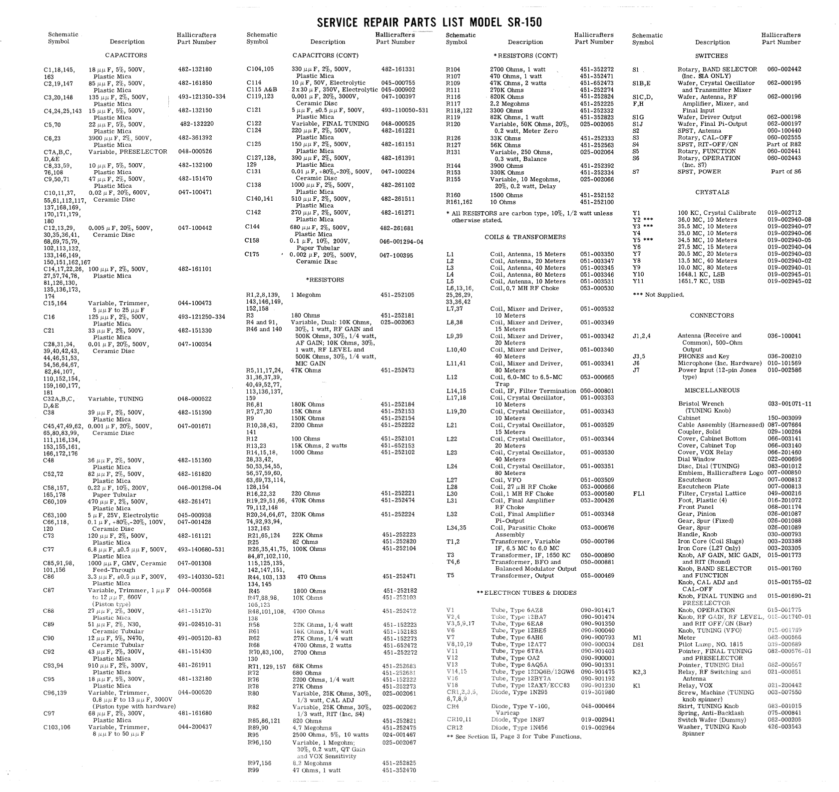
Schematic
Symbol
Cl,18,145,
163
C2,19,147
C3,20,148
C4,24,25,143
C5,70
C6,23
C7A,B,C,
D,&E
C8,33,59,
76,108
C9,50,71
Description
CAPACITORS
181l1lF,
5%, 500V,
Plastic
Mica
85
Illl
F,
2%, 500V,
Plastic
Mica
135
IlIlF,
2%, 500V,
Plastic
Mica
151l1lF,
5%,
500V,
Plastic
Mica
22
IlIlF,
5%, 500V,
Plastic
Mica
3900
/lI.L
F,
2'1'-,
500V,
Plastic
Mica
Variable,
PRESELECTOR
10
1"11
F,
5%, 500V,
Plastic
Mica
47
IlIlF,
20/"
500V,
Plastic
Mica
Cl0,11,37,
000211
F,
20%, 600V,
55,61,112,117,
Ceramic
Disc
137,168,169,
170,171,179,
180
C12,13,29,
30,35,36,41,
68,69,75,79,
102,113,132,
133,146,149,
0.005
I"
F,
20%, 500V,
Ceramic
Disc
150,151,162,167
C14,17,22,26,
100
IlIlF,
2%, 500V,
27,57,74,78,
Plastic
Mica
81,126,130,
135,136,173,
174
C15,164
C16
C21
C28,31,34,
39,40,42,43,
44,46,51,53,
54,56,64,67,
82,84,107,
110,152,154,
159,160,177,
181
C32A,B,C,
D,&E
C38
C45,47,49,62,
65,80,83,99,
111,116,134,
153,155,161,
166,172,176
C48
C52,72
C58,157,
165,178
C60,109
C63,100
C66,118,
120
C73
C77
C85,91,98,
101,156
C86
C87
CB8
C89
C90
C92
C93,94
C95
Variable,
Trimmer,
51lllF
to
251lllF
125 Illl
F,
2%, 500V,
Plastic
MiCa
33
I'll
F,
2%, 500V,
Plastic
Mica
O.OIIlF,
20%, 500V,
Ceramic
Disc
Variable,
TUNING
39 Illl
F,
2%, 500V,
Plastic
Mica
0~001
Il
F,
20%, 500V,
Ceramic
Disc
361l1lF,
2%, 500V,
Plastic
Mica
821l1lF,
2%, 500V,
Plastic
Mica
0.22IlF,
10%, 200V,
Paper
Tubular
470IlIlF,
2%, 500V,
Plastic
Mica
5
11
F,
25V,
Electrolytic
001
IlF,
+80%,-20%, 100V,
Ceramic
Disc
1201l~F,
2%, 500V,
Plastic
Mica
6~8
Illl
F,
±0,5 Illl
F,
500V,
Plastic
Mica
1000 Illl
F,
GMV,
Ceramic
Feed-Through
3.3
~Il
F,
±0,5
1111
F,
300V,
Plastic
Mica
Nil.e;;}
51
MIL
FJ
29;"
N30,
Ceramic
Tubular
12
I'll
F,
5%, N470,
Ceramic
Tubular
43
IlIlF,
2%,
300V,
Plastic
Mica
910
Illl
F,
2%,
300V,
Plastic
Mica
181"1lF,
5%,
300V,
Plastic
Mica
Hallicraiters
Part
Number
482-132180
482-161850
493-121350-334
482-132150
482-132220
482-361392
048-000526
482-132100
482-151470
047-100471
047-100442
482-161101
044-100473
493-121250-334
482-151330
047-100354
048-000522
482-151390
047-001671
482-151360
482-161820
046-001298-04
482-261471
045-000938
047-001428
482-161121
493-140680-531
047-001308
493-140330-521
044-000568
481-151270
491-024510-31
491-005120-83
481-151430
481-261911
481-132180
C96,139
Variable,
Trimmer)
044-000520
C97
Cl03,106
008
I'll
F
to
13
Ill'
F,
3000V
(Piston
type
with
hardware)
681'IlF,
2%,
300V,
481-161680
Plastic
Mica
Variable,
Trimmer,
8
~~F
to
50
i"ilF
044-200437
SERVICE
REPAIR
PARTS
LIST
MODEL
SR-150
Schematic
Symbol
Description
Hallicrafters
Part
Number
C104,105
C114
C115
A&B
C119,123
C121
C122
C124
C125
CI27,128,
129
C131
C138
C140,141
C142
C144
C158
C175
R1,2,8,139,
143,146,149,
152,158
R3
R4
and
91,
R46
and
140
R5,1l,17,24,
31,36,37,39,
40,49,52,77,
113,136,137,
159
R6,81
R7,27,30
R9
Rl0,38,43,
141
R12
R13,23
RI4,15,18,
28,33,42,
50,53,54,55,
56,57,59,60,
63,69,73,114,
128,154
CAPACITORS
(CONT)
3301l1lF,
2%, 500V,
Plastic
Mica
10
Il
F,
50V,
Electrolytic
2 x 30
Il
F,
350V,
Electrolytic
0.001
Il
F,
20%, 3000V,
Ceramic
Disc
51l1lF,
±0,51lIlF,
500V,
Plastic
Mica
Variable,
FINAL
TUNING
220IlIlF,
2%, 500V,
Plastic
Mica
150 Illl
F,
2%, 500V,
Plastic
Mica
390
IlIlF,
2%, 500V,
Plastic
Mica
0.01
Il
F,
+80%,-20%, 500V,
Ceramic
Disc
lOOOIlIlF,
2%, 500V,
Plastic
Mica
510IlIlF,
2%, 500V,
Plastic
Mica
270 Illl
F,
2%, 500V,
Plastic
Mica
680 Illl
F,
2%,
500V,
Plastic
Mica
0.1
IlF,
10%, 200V,
Paper
Tubular
0.002
IlF,
20%, 500V,
Ceramic
Disc
*RESISTORS
I
Megohm
180
Ohms
Variable,
Dual: 10K
Ohms,
30%, 1
watt,
RF
GAIN
and
500K
Ohms,
30%,
1/4
watt,
AF
GAIN;
10K
Ohms,
30%,
1
watt,
RF
LEVEL
and
500K
Ohms,
30%,
1/4
watt,
MIC GAIN
47K
Ohms
180K
Ohms
15K
Ohms
150K
Ohms
2200
Ohms
100
Ohms
15K
Ohms,
2
watts
1000
Ohms
RI6,22,32
220
Ohms
RI9,29,51,66,
470K
Ohms
79,112,148
R20,34,64,67,
220K
Ohms
74,92,93,94,
132,163
R21,65,124
22K
Ohms
R25 82
Ohms
R26,35,41,75,
lOOK
Ohms
84,87,102,110,
115,125,135,
142,147,151,
R44,
103,
133
134,145
R45
138
R58
E6!
R62
R68
R70,83,100,
130
R71,
129,
157
R72
R76
R78
R80
R82
H85,86,121
R89,90
R95
R96,150
R97,156
R99
470
Ohms
1800
Ohms
10K
Obms
4700
Ohms
22K
Ohms,
1;·1
watt
16K
Ohms,
1/4
watt
27K
Ohms,
1/4
walt
4700
Ohms,
2
watts
2700
Ohms
68K
Ohms
680
Ohms
2200
Ohms,
1/4
watt
27K
Ohms
Variable,
25K
Ohms,
30%,
1/3
watt,
CAL
ADJ
VarIable,
25K
Ohms,
30%,
1/3
watt,
RIT
(Inc. S4)
820
Ohms
407
MEgohms
2500
Ohms,
5%1
10
watts
1
482-161331
045-000755
045-000902
047-100397
493-110050-531
048-000525
482-161221
482-161151
482-161391
047-100224
482-261102
482-261511
482-161271
482-261681
046-001294-04
047-100395
451-252105
451-252181
025-002063
451-252473
451-252184
451-252153
451-252154
451-252222
451-252101
451-652153
451-252102
451-252221
451-252474
451-252224
451-252223
451-252820
451-252104
451-252471
451-252182
451-2"2103
451-2521?2
45]"
152223
451,,152183
451-152273
451,,652472
451-252272
451,~25268:;
451
451-152222
451-252273
025-002061
025-002062
451-252821
451-252475
024-001467
025-0()2067
451-252825
451-352470
Schematic
Symbol
R104
Rl07
Rl09
Rll1
R116
R117
R118,122
R119
R120
R126
R127
R131
R144
R153
R155
R160
R161,162
Description
* RESISTORS (CONT)
2700
Ohms,
1
watt
470
Ohms,
1
watt
47K
Ohms,
2
watts
270K
Ohms
820K,Ohms
2.2
Megohms
3300
Ohms
82K
Ohms,
1
watt
Variable,
50K
Ohms,
20%,
0.2
watt,
Meter
Zero
33K
Ohms
56K
Ohms
Variable,
250
Ohms,
0.3
watt,
Balance
3900
Ohms
330K
Ohms
Variable,
10
Megohms,
20%,
0.2
watt,
Delay
1500
Ohms
10
Ohms
Hallicrafters
Part
Number
451-352272
451-352471
451-652473
451-252274
451-252824
451-252225
451-252332
451-352823
025-002065
451-252333
451-252563
025-002064
451-252392
451-252334
025-002066
451-252152
451-252100
*
All
RESISTORS
are
carbon
type,
10%,
1/2
watt
unless
otherwise
statecL
Ll
L2
L3
L4
L5
L6,13,16,
25,26,29,
33,36,42
L7,37
L8,38
L9,39
LlO,40
Lll,41
L12
L14,15
L17,18
L19,20
L21
L22
L23
L24
L27
L28
L30
L31
L32
L34,35
Tl,2
T3
T4,6
T5
Vi
V7
V8,lO,19
Vll
Via
1,'1.8
CR4
COILS
&
TRANSFORMERS
Coil,
Antenna,
15
Meters
Coil,
Antelma, 20
Meters
Coil,
Antenna,
40
Meters
Coil,
Antenna,
80
Meters
Coil,
Antenna,
10
Meters
Coil,
0.7
MH
RF
Choke
Coil,
Mixer
and
Driver,
10
Meters
COil,
Mixer
and
Driver,
15
Meters
Coil,
Mixer
and
Driver,
20
Meters
Coil,
Mixer
and
Driver,
40
Meters
Coil,
Mixer
and
Driver,
80
Meters
Coil,
600-MC
to
605-MC
Trap
Coil,
IF,
Filter
Termination
Coil,
Crystal
Oscillator,
10
Meters
Coil,
Crystal
OSCillator,
10
Meters
Coil,
Crystal
Oscillator,
15
Meters
Coil,
Crystal
Oscillator,
20
Meters
Coil,
Crystal
Oscillator,
40
Meters
Coil,
Crystal
Oscillator,
80
Meters
Coil,
VFO
Coil,
27
IlH
RF
Choke
Coil,
1 MH
RF
Choke
Coil,
Final
Amplifier
RF
Choke
Coil,
Final
Amplifier
Pi-Output
Coil,
Parasitic
Choke
Assembly
Transformer,
Variable
IF,
605
MC
to
600
MC
Transformer,
IF,
1650
KC
Transformer,
BFO
and
Balanced
Modulator
OUtput
Transformer,
Output
**ELECTHON
TUBES
& DIODES
Typt:
6AZB
Type
Tyl'''
6EA8
Tube,
Type
12BE6
Tube,
TYVe
6AH6
Tube,
Type
12AT7
Tube,
Type
6TEA
Tube,
Type
OA2
Tube,
Type
6AQ5A
Type
Type
Type
12AX7/ECCB3
Type
lN295
lN87
CR12
Diode"
Type
lN456
051-003350
051-003347
051-003345
051-003346
051-003531
053-000530
051-003532
051-003349
051-003342
051-003340
051-003341
053-000665
050-000801
051-003353
051-003343
051-003529
051-003344
051-003530
051-003351
051-003509
053-000666
053-000580
053-200426
051-003348
053-000676
050-000786
050-000890
050-000881
055-000469
090-901417
()90-901474
090-901350
090-900040
090-900793
090-000034
090-901403
090-900001
090-901331
090-901475
090-901192
019-301980
048-000464
019-002941
019-002964
** See Seetion HJ
Page
3
for
Tube
Functions,
Schematic
Symbol
SI
SIB,E
SIC,D,
F,H
SIG
SIJ
S2
S3
S4
S5
S6
S7
Yl
Y2
***
Y3 ***
Y4
Y5
***
Y6
Y7
Y8
Y9
YIO
Yll
Description
SWITCHES
Rotary,
BAND
SELECTOR
(Inc.
SlA ONLY)
Wafer,
Crystal
Oscillator
and
Transmitter
Mixer
Wafer,
Antenna,
RF
Amplifier,
Mixer,
and
Final
Input
Wafer,
Driver
Output
Wafer,
Final
Pi-OUtput
SPST,
Antenna
Rotary,
CAL-OFF
SPST,
RIT-OFF/ON
Rotary,
FUNCTION
Rotary,
OPERATION
(Inc.
S7)
SPST,
POWER
CRYSTALS
100 KC,
Crystal
Calibrate
36,0
MC, 10
Meters
35.5
MC, 10
Meters
35.0
MC, 10
MeterS
3405 MC, 10
Meters
2705 MC, 15
Meters
2005 MC, 20
Meters
13.5
MC, 40
Meters
1000 MC,
80
Meters
164801 KC, LSB
1651.7 KC, USB
Hallicraiters
Part
Number
060-002442
062-000195
062-000196
062-000198
062-000197
060-100440
060-002555
Part
of
R82
060-002441
060-002443
Part
of
86
019-002712
019-002940-08
019-002940-07
019-002940-06
019-002940-05
019-002940-04
019-002940-03
019-002940-02
019-002940-01
019-002945-01
019-002945-02
***
Not
Suppliedo
Jl,2,4
J3,5
J6
J7
FLI
Ml
DS!
1(2,3
Kl
CONNECTORS
Antenna
(Receive
and
Common),
500-0hm
Output
PHONES
and
Key
Microphone
(lnco
Hardware)
Power
Input
(12-pin
Jones
type)
MISCELLANEOUS
Bristol
Wrench
(TUNING Knob)
Cabinet
Cable
Assembly
(Harnessed)
Coupler,
Solid
Cover,
Cabinet
Bottom
Cover,
Cabinet
Top
Cover,
VOX
Relay
Dial
Window
Disc,
Dial
(TUNING)
Emblem,
Hallicrafters
Logo
Escutcheon
Escutcheon
Plate
Filter,
Crystal
Lattice
Foot,
Plastic
(4)
Front
Panel
Gear,
Pinion
Gear,
Spur
(Fixed)
Gear,
Spur
Handle,
Knob
Iron
Core
(Coil
Slugs)
Iron
Core
(L27
Only)
Knob,
AF
GAIN, MIC GAIN,
and
RIT
(Round)
Knob, BAND
SELECTOR
and
FUNCTION
Knob,
CAL
ADJ
and
CAL-OFF
Knob,
FINAL
TUNING and
PRESELECTOR
NO. 1815
Pointer,
TUNlliC
and
PHESELECTOR
POinter,
TUNING
Dial
Relay,
RF
Swilchmg
and
Antenna
Relay,
VOX
Screw,
Machine
(TUNiNG
knob
spinner)
Skirt,
TUNll'iG Knob
Spring,
Anti-Backlash
Switch
Wafer
Washer,
TUNING
6'pinner
036-100041
036-200210
010-101569
010-002586
033-001071-11
150-003099
087-007664
029-100264
066-003141
066-003140
066-201460
022-000696
083-001012
007-000850
007-000812
007-000813
049-000216
016-201072
068-001174
026-001087
026-001088
026-001089
030-000793
003-203388
003-203305
015-001773
015-001760
015-001755-02
015-001690-21
Ol5-GG1T75
140,,01
083·001015
075-000841
052-()00205
426·003543

094-9032868
563
Printed
in U.S.A.
