Book.bk MOMENTUS ST9120312AS 100513273a
User Manual: MOMENTUS ST9120312AS
Open the PDF directly: View PDF ![]() .
.
Page Count: 60
- 1.0 Introduction
- 2.0 Drive specifications
- 2.1 Specification summary table
- 2.2 Formatted capacity
- 2.3 Default logical geometry
- 2.4 Physical organization
- 2.5 Recording and interface technology
- 2.6 Physical characteristics
- 2.7 Seek time
- 2.8 Start/stop times
- 2.9 Power specifications
- 2.10 Environmental specifications
- 2.11 Acoustics
- 2.12 Electromagnetic immunity
- 2.13 Reliability
- 2.14 Agency certification
- 2.15 Environmental protection
- 2.16 Corrosive environment
- 3.0 Configuring and mounting the drive
- 4.0 Serial ATA interface
- 5.0 Compatibility summary
- 6.0 Seagate Technology support services
Product Manual
Momentus® 5400 FDE.3 SATA
100513273
Rev. A
June 2008
ST9320322AS
ST9160312AS
ST9120312AS
©2008, Seagate Technology LLC All rights reserved.
Publication number: 100513273, Rev. A
June 2008
Seagate, Seagate Technology and the Wave logo are registered trademarks of Seagate
Technology LLC in the United States and/or other countries. Momentus, Seagate-
SeaBOARD, SeaFONE, SeaTDD, and SeaTools are either trademarks or registered trade-
marks of Seagate Technology LLC or one of its affiliated companies in the United States and/
or other countries. All other trademarks or registered trademarks are the property of their
respective owners.
One gigabyte, or GB, equals one billion bytes and one terabyte, or TB, equals one trillion
bytes when referring to hard drive capacity. Accessible capacity may vary depending on
operating environment and formatting. Quantitative usage examples for various applications
are for illustrative purposes. Actual quantities will vary based on various factors, including file
size, file format, features and application software. Seagate reserves the right to change,
without notice, product offerings or specifications.

Momentus 5400 FDE.3 SATA Product Manual, Rev. A
i
Contents
1.0 Introduction. . . . . . . . . . . . . . . . . . . . . . . . . . . . . . . . . . . . . . . . . . . . . . . . . . . . . . . . . . . . . . . . . . . 1
1.1 System requirements. . . . . . . . . . . . . . . . . . . . . . . . . . . . . . . . . . . . . . . . . . . . . . . . . . . . . . 1
1.2 About Momentus 5400 FDE.3 SATA disc drives. . . . . . . . . . . . . . . . . . . . . . . . . . . . . . . . . 2
1.2.1 Drive state upon shipment . . . . . . . . . . . . . . . . . . . . . . . . . . . . . . . . . . . . . . . . . . 3
2.0 Drive specifications . . . . . . . . . . . . . . . . . . . . . . . . . . . . . . . . . . . . . . . . . . . . . . . . . . . . . . . . . . . . 5
2.1 Specification summary table . . . . . . . . . . . . . . . . . . . . . . . . . . . . . . . . . . . . . . . . . . . . . . . . 5
2.2 Formatted capacity . . . . . . . . . . . . . . . . . . . . . . . . . . . . . . . . . . . . . . . . . . . . . . . . . . . . . . 7
2.2.1 LBA mode . . . . . . . . . . . . . . . . . . . . . . . . . . . . . . . . . . . . . . . . . . . . . . . . . . . . . . 7
2.3 Default logical geometry . . . . . . . . . . . . . . . . . . . . . . . . . . . . . . . . . . . . . . . . . . . . . . . . . . . 7
2.4 Physical organization . . . . . . . . . . . . . . . . . . . . . . . . . . . . . . . . . . . . . . . . . . . . . . . . . . . . . 8
2.5 Recording and interface technology . . . . . . . . . . . . . . . . . . . . . . . . . . . . . . . . . . . . . . . . . . 8
2.6 Physical characteristics . . . . . . . . . . . . . . . . . . . . . . . . . . . . . . . . . . . . . . . . . . . . . . . . . . . 8
2.7 Seek time. . . . . . . . . . . . . . . . . . . . . . . . . . . . . . . . . . . . . . . . . . . . . . . . . . . . . . . . . . . . . . . 9
2.8 Start/stop times . . . . . . . . . . . . . . . . . . . . . . . . . . . . . . . . . . . . . . . . . . . . . . . . . . . . . . . . . . 9
2.9 Power specifications . . . . . . . . . . . . . . . . . . . . . . . . . . . . . . . . . . . . . . . . . . . . . . . . . . . . . 10
2.9.1 Power consumption . . . . . . . . . . . . . . . . . . . . . . . . . . . . . . . . . . . . . . . . . . . . . . 10
2.9.2 Deferred spinup . . . . . . . . . . . . . . . . . . . . . . . . . . . . . . . . . . . . . . . . . . . . . . . . . 11
2.9.3 Conducted noise . . . . . . . . . . . . . . . . . . . . . . . . . . . . . . . . . . . . . . . . . . . . . . . . 11
2.9.4 Voltage tolerance . . . . . . . . . . . . . . . . . . . . . . . . . . . . . . . . . . . . . . . . . . . . . . . . 11
2.9.5 Power-management modes. . . . . . . . . . . . . . . . . . . . . . . . . . . . . . . . . . . . . . . . 12
2.10 Environmental specifications. . . . . . . . . . . . . . . . . . . . . . . . . . . . . . . . . . . . . . . . . . . . . . . 13
2.10.1 Ambient temperature . . . . . . . . . . . . . . . . . . . . . . . . . . . . . . . . . . . . . . . . . . . . . 13
2.10.2 Temperature gradient. . . . . . . . . . . . . . . . . . . . . . . . . . . . . . . . . . . . . . . . . . . . . 13
2.10.3 Humidity . . . . . . . . . . . . . . . . . . . . . . . . . . . . . . . . . . . . . . . . . . . . . . . . . . . . . . . 13
2.10.4 Altitude . . . . . . . . . . . . . . . . . . . . . . . . . . . . . . . . . . . . . . . . . . . . . . . . . . . . . . . . 13
2.10.5 Shock . . . . . . . . . . . . . . . . . . . . . . . . . . . . . . . . . . . . . . . . . . . . . . . . . . . . . . . . . 14
2.10.6 Vibration. . . . . . . . . . . . . . . . . . . . . . . . . . . . . . . . . . . . . . . . . . . . . . . . . . . . . . . 14
2.11 Acoustics . . . . . . . . . . . . . . . . . . . . . . . . . . . . . . . . . . . . . . . . . . . . . . . . . . . . . . . . . . . . . . 15
2.12 Electromagnetic immunity . . . . . . . . . . . . . . . . . . . . . . . . . . . . . . . . . . . . . . . . . . . . . . . . . 15
2.13 Reliability . . . . . . . . . . . . . . . . . . . . . . . . . . . . . . . . . . . . . . . . . . . . . . . . . . . . . . . . . . . . . 16
2.14 Agency certification . . . . . . . . . . . . . . . . . . . . . . . . . . . . . . . . . . . . . . . . . . . . . . . . . . . . . . 16
2.14.1 Safety certification . . . . . . . . . . . . . . . . . . . . . . . . . . . . . . . . . . . . . . . . . . . . . . . 16
2.14.2 Electromagnetic compatibility. . . . . . . . . . . . . . . . . . . . . . . . . . . . . . . . . . . . . . . 16
2.14.3 FCC verification . . . . . . . . . . . . . . . . . . . . . . . . . . . . . . . . . . . . . . . . . . . . . . . . . 17
2.15 Environmental protection. . . . . . . . . . . . . . . . . . . . . . . . . . . . . . . . . . . . . . . . . . . . . . . . . . 18
2.15.1 European Union Restriction of Hazardous Substances (RoHS) . . . . . . . . . . . . 18
2.15.2 China Restriction of Hazardous Substances (RoHS) Directive . . . . . . . . . . . . . 18
2.16 Corrosive environment . . . . . . . . . . . . . . . . . . . . . . . . . . . . . . . . . . . . . . . . . . . . . . . . . . . 18
3.0 Configuring and mounting the drive . . . . . . . . . . . . . . . . . . . . . . . . . . . . . . . . . . . . . . . . . . . . . 19
3.1 Handling and static-discharge precautions . . . . . . . . . . . . . . . . . . . . . . . . . . . . . . . . . . . . 19
3.2 Configuring the drive . . . . . . . . . . . . . . . . . . . . . . . . . . . . . . . . . . . . . . . . . . . . . . . . . . . . . 20
3.3 Serial ATA cables and connectors . . . . . . . . . . . . . . . . . . . . . . . . . . . . . . . . . . . . . . . . . . 20
3.4 Drive mounting . . . . . . . . . . . . . . . . . . . . . . . . . . . . . . . . . . . . . . . . . . . . . . . . . . . . . . . . . 21
3.5 Drive integration . . . . . . . . . . . . . . . . . . . . . . . . . . . . . . . . . . . . . . . . . . . . . . . . . . . . . . . . 22
3.5.1 Drive installation. . . . . . . . . . . . . . . . . . . . . . . . . . . . . . . . . . . . . . . . . . . . . . . . . 23
3.5.2 Consumer usage . . . . . . . . . . . . . . . . . . . . . . . . . . . . . . . . . . . . . . . . . . . . . . . . 23
3.6 Security Erase--ATA security commands . . . . . . . . . . . . . . . . . . . . . . . . . . . . . . . . . . . . . 23
3.6.1 Secure Erase procedure . . . . . . . . . . . . . . . . . . . . . . . . . . . . . . . . . . . . . . . . . . 23
3.6.2 Drive State after Secure Erase . . . . . . . . . . . . . . . . . . . . . . . . . . . . . . . . . . . . . 24

ii
Momentus 5400 FDE.3 SATA Product Manual, Rev. A
4.0 Serial ATA interface . . . . . . . . . . . . . . . . . . . . . . . . . . . . . . . . . . . . . . . . . . . . . . . . . . . . . . . . . . . 25
4.1 Hot-Plug compatibility . . . . . . . . . . . . . . . . . . . . . . . . . . . . . . . . . . . . . . . . . . . . . . . . . . . . 25
4.2 Serial ATA device plug connector pin definitions. . . . . . . . . . . . . . . . . . . . . . . . . . . . . . . . 25
4.2.1 ATA Security policy exceptions . . . . . . . . . . . . . . . . . . . . . . . . . . . . . . . . . . . . . 26
4.2.2 DriveTrust Mode support . . . . . . . . . . . . . . . . . . . . . . . . . . . . . . . . . . . . . . . . . . 28
4.2.3 Full Disc Encryption support. . . . . . . . . . . . . . . . . . . . . . . . . . . . . . . . . . . . . . . . 29
4.2.4 Supported ATA commands . . . . . . . . . . . . . . . . . . . . . . . . . . . . . . . . . . . . . . . . 30
4.2.5 Identify Device command . . . . . . . . . . . . . . . . . . . . . . . . . . . . . . . . . . . . . . . . . . 34
4.2.6 Set Features command . . . . . . . . . . . . . . . . . . . . . . . . . . . . . . . . . . . . . . . . . . . 37
4.2.7 S.M.A.R.T. commands . . . . . . . . . . . . . . . . . . . . . . . . . . . . . . . . . . . . . . . . . . . . 38
5.0 Compatibility summary . . . . . . . . . . . . . . . . . . . . . . . . . . . . . . . . . . . . . . . . . . . . . . . . . . . . . . . . 39
5.1 Installation considerations . . . . . . . . . . . . . . . . . . . . . . . . . . . . . . . . . . . . . . . . . . . . . . . . . 39
5.2 System Compatibility using WIndows XP SP2. . . . . . . . . . . . . . . . . . . . . . . . . . . . . . . . . . 39
5.2.1 BIOS versions tested in ATA Security mode . . . . . . . . . . . . . . . . . . . . . . . . . . . 39
5.2.2 DriveTrust compatibility verification . . . . . . . . . . . . . . . . . . . . . . . . . . . . . . . . . . 42
5.3 Operating system versions tested . . . . . . . . . . . . . . . . . . . . . . . . . . . . . . . . . . . . . . . . . . . 46
5.4 Compatibility test configurations . . . . . . . . . . . . . . . . . . . . . . . . . . . . . . . . . . . . . . . . . . . . 46
6.0 Seagate Technology support services . . . . . . . . . . . . . . . . . . . . . . . . . . . . . . . . . . . . . . . . . . . . 47

Momentus 5400 FDE.3 SATA Product Manual, Rev. A
iii
List of Figures
Figure 1. Typical +5V only startup and operation current profile . . . . . . . . . . . . . . . . . . . . . . . . . . . . . . 11
Figure 2. Serial ATA connectors . . . . . . . . . . . . . . . . . . . . . . . . . . . . . . . . . . . . . . . . . . . . . . . . . . . . . . 20
Figure 3. Attaching SATA cabling . . . . . . . . . . . . . . . . . . . . . . . . . . . . . . . . . . . . . . . . . . . . . . . . . . . . . 20
Figure 4. Mounting dimensions . . . . . . . . . . . . . . . . . . . . . . . . . . . . . . . . . . . . . . . . . . . . . . . . . . . . . . . 21
Figure 5. Momentus 5400 FDE.3 SATA drive label example . . . . . . . . . . . . . . . . . . . . . . . . . . . . . . . . 22

Momentus 5400 FDE.3 SATA Product Manual, Rev. A
1
1.0 Introduction
This manual describes the functional, mechanical and interface specifications for the following Seagate
Momentus® 5400 FDE.3 SATA model drives:
These drives provide the following key features:
• DriveTrust technology including:
• Hardware-based Full Disc Encryption (FDE)
• DriveTrust security interface and ATA security interface
• Integrates with standard security software packages to provide features such as: Pre-boot authentica-
tion and initialization using the drive’s secure partition and DriveTrust API
• 5,400-RPM spindle speed
• 8-Mbyte buffer
• Quiet operation. Fluid Dynamic Bearing (FDB) motor.
• High instantaneous (burst) data transfer rates (up to 100 Mbytes per second) using Ultra DMA mode 6.
• State-of-the-art cache and on-the-fly error-correction algorithms.
• Full-track multiple-sector transfer capability without local processor intervention.
•1,000 Gs nonoperating shock and 350 Gs operating shock.
• SeaTools™ diagnostic software performs a drive self-test that eliminates unnecessary drive returns.
• Support for S.M.A.R.T. drive monitoring and reporting.
• Support for Read Multiple and Write Multiple commands.
1.1 System requirements
The following hardware and software is required to use these drives.
Host system requirements:
• Windows XP with Service Pack 2 (or later) when utilizing the Windows DriveTrust API.
• System/BIOS that supports ATA Security commands.
ST9320322AS
ST9160312AS
ST9120312AS
2
Momentus 5400 FDE.3 SATA Product Manual, Rev. A
1.2 About Momentus 5400 FDE.3 SATA disc drives
The Momentus® 5400 FDE.3 SATA drives contain DriveTrust technology providing Full Disc Encryption (FDE)
using proven Advanced Encryption Standard (AES) data encryption and decryption.
You can elect to use Momentus 5400 FDE.3 SATA drives in one of two different security modes:
1. The ATA Security mode
To operate in ATA Security mode, you only need a host system and operating system that supports the
existing ATA Security Command Set. The drive is shipped to operating in this mode, ready to use.
2. The DriveTrust Security mode
To enable a robust enterprise-level security and management policy, you may elect to operate in
DriveTrust Security mode. To do so, you will need to use a third-party security application to manage the
DriveTrust features. Please contact your system or software provider for more details.
Refer to the table below to determine which mode is best for your particular solution.
FDE drive feature list
• Automatically encrypts (and decrypts) all data on the drive
• Operations are performed with no measurable performance loss
• All user data is encrypted on write operations and decrypted on read operations
FDE benefits
• Drive-level protection of data
• Drives that are stolen, taken out of service, or re-purposed remain fully protected
• Near instantaneous disposal and re-purposing of the drive (ensures that data from previous user is not
accessible by the new drive owner)
• Able to be deployed within a trusted computing environment
The drive encrypts every write operation and decrypts every read operation without user intervention. The
encryption and decryption is done on the drive itself, so there is a near-zero performance impact when the
drive writes and reads data. The performance-optimized encryption and decryption engine performs at the
SATA interface speed.
The purpose of full disc encryption on the drive is to protect the data stored on the drive in the event that the
host system is lost or stolen. This data at rest protection assures the system owner that if their system is lost or
stolen, their data will not be accessible without the correct credentials.
Note. The system reauthenticates the user on powerup and when awakening from sleep mode. It is not
necessary to power down to ensure that the system reauthenticates the user.
Table 1: Security feature matrix
ATA Security mode DriveTrust mode
Feature
Non-FDE drive
without ATA Security
enabled Non-FDE drive with
ATA Security enabled FDE drive with ATA
Security enabled
FDE drive operating in
DriveTrust mode via
third-party software
Password required to unlock No Yes Yes Yes
Full Disk Encryption No No Yes Yes
At speed encryption No No Yes Yes
Passwords stored securely No Yes Yes Yes
Quick erase No No Yes Yes
Preboot authentication No No No Yes
Master/User passwords No No No Yes

Momentus 5400 FDE.3 SATA Product Manual, Rev. A
3
Having the encryption/decryption on the drive also provides the highest level of security for data because all
data, including the boot sector bytes, operating system, temp and even the swap files are encrypted at the
drive level.
1.2.1 Drive state upon shipment
Upon shipment from the Seagate factory, the ATA Security Interface is enabled and functioning. This is
referred to as operating in ATA Security mode. The following is the detailed state of the drive upon shipment.
• Full Disc Encryption is active and functioning. All user data is encrypted on write and decrypted on read.
• The user interface to the drive is active and all read and write commands are allowed.
• The ATA user password is null (no value).
• The ATA master password is set to the Security ID (SID).
• ATA Security is set to the unlocked state. No password is required to access the drive.
Momentus 5400 FDE.3 SATA drives may be integrated into the computer system in the same way you would
integrate a non-FDE Momentus drive.
The encryption key is enabled and operational when the drive leaves the Seagate factory. No user id is
required to access the drive, so the data on the drive is accessible to anyone possessing the drive.

4
Momentus 5400 FDE.3 SATA Product Manual, Rev. A
Momentus 5400 FDE.3 SATA Product Manual, Rev. A
5
2.0 Drive specifications
Unless otherwise noted, all specifications are measured under ambient conditions, at 25°C, and nominal
power.
2.1 Specification summary table
The specifications listed in this table are for quick reference. For details on specification measurement or defi-
nition, see the appropriate section of this manual.
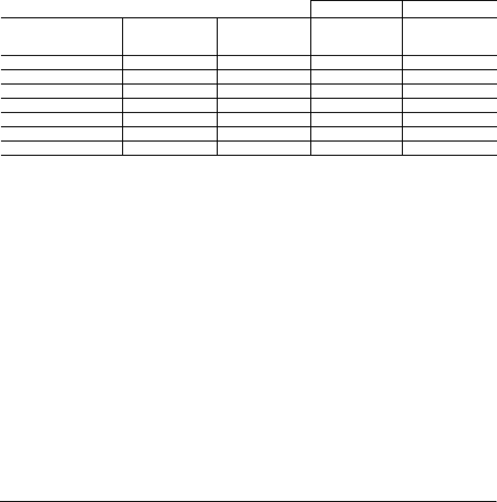
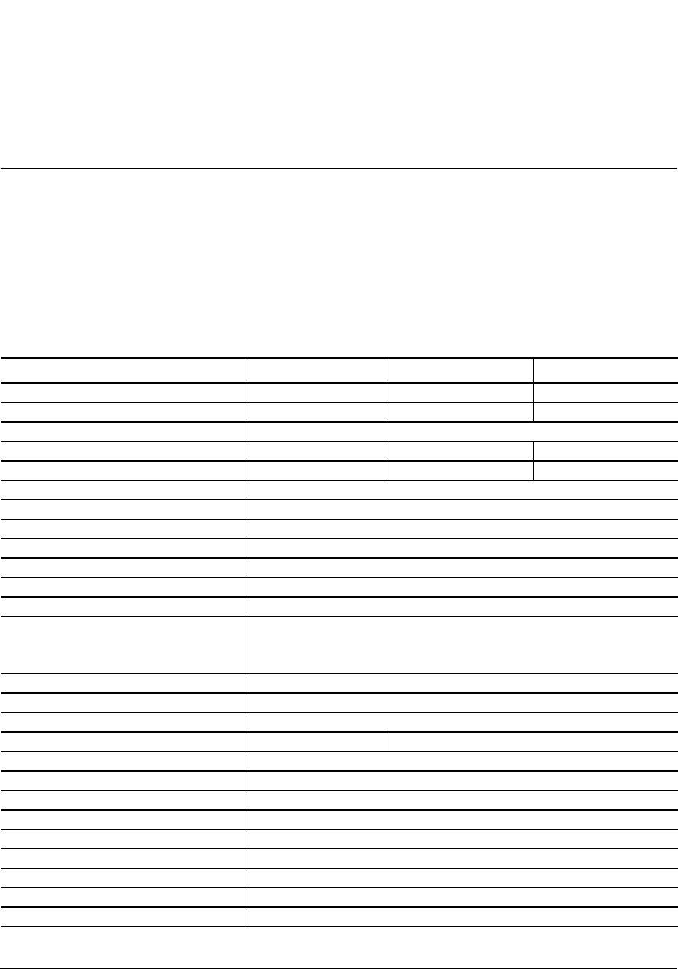
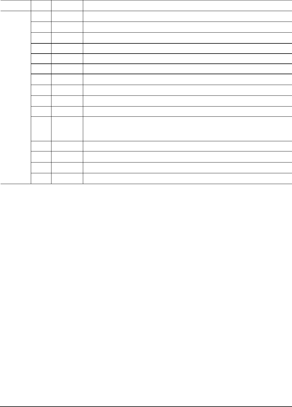
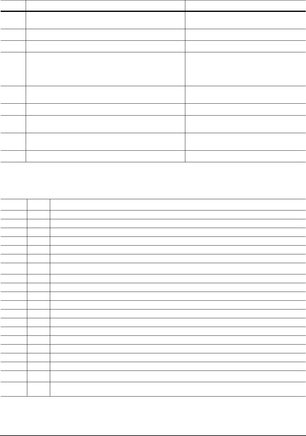
Table 2: Drive specifications
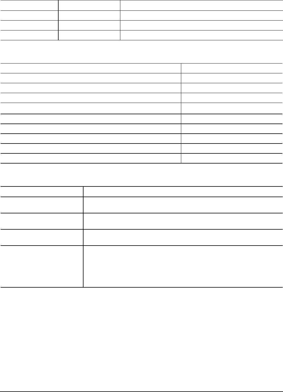
Drive specification ST9320322AS ST9160312AS ST9120312AS
Formatted Gbytes (512 bytes/sector)* 320 160 120
Guaranteed sectors 625,142,448 312,581,808 234,441,648
Bytes per sector 512
Physical read/write heads 4 2 2
Discs 2 1 1
Cache (Mbytes) 8
Recording density in BPI (bits/inch max) 1,337k
Track density TPI (tracks/inch max) 191.5k
Areal density (Gbits/inch2 max) 253
Spindle speed (RPM) 5,400
Internal transfer rate (Mbits/sec max) 830
I/O data transfer rate (Gbits/sec max) 3.0
ATA data-transfer modes supported SATA 1.5/3.0, Serial ATA Revision 2.6
PIO modes 0–4
Multiword DMA modes 0–2
Ultra DMA modes 0–6
Height (max) 9.5 +/- 0.2 mm (0.374 +/- .0078 inches)
Width (max) 69.85 +/- 0.249 mm (2.75 +/- 0.0098 inches)
Length (max) 100.33 +/- 0.25 mm (3.95 +/- 0.010 inches)
Weight (typical) 98 grams (0.212 lb) 93 grams (0.205 lb)
Average latency (msec) 5.6
Power-on to ready (sec typical) 3.4
Standby to ready (sec typical) 3.2
Track-to-track seek time, read (msec typical) 1.5
Average seek, read (msec typical) 11.0
Full-stroke seek, read (msec) 24 (typical)
Startup current, +5V (max) 1.0 amps
Seek power (typical) 2.0 watts
Read/write power (typical) Read: 1.6 watts; Write: 1.9 watts

6
Momentus 5400 FDE.3 SATA Product Manual, Rev. A
*One Gbyte equals one billion bytes when referring to hard drive capacity. Accessible capacity may vary depending on operating environment
and formatting.
**During periods of drive idle, some offline activity may occur according to the S.M.A.R.T. specification, which may increase acoustic and
Idle mode, low power (typical) 0.7 watts
Standby mode 0.24 watts (typical)***
Sleep mode 0.24 watts (typical)***
Voltage tolerance (including noise) +5V ± 5%
Ambient temperature 0° to 60°C (operating), –40° to 70°C (nonoperating)
Temperature gradient (°C per hour max) 20°C (operating)
35°C (nonoperating)
Relative humidity 5% to 95% (operating)
5% to 95% (nonoperating)
Relative humidity gradient 30% per hour max
Wet bulb temperature (max) 37.7°C (operating)
40°C (nonoperating)
Altitude, operating –60.96 m to 3,048 m (–200 ft to 10,000+ ft)
Altitude, nonoperating
(meters below mean sea level, max) –304.8 m to 12,192 m (–1000 ft to 40,000+ ft)
Shock, operating
(Gs max at 2 msec) 350
Shock, nonoperating
(Gs max at 2 msec) 800
Shock, nonoperating
(Gs max at 1 msec) 1,000
Shock, nonoperating
(Gs max at 0.5 msec) 600
Vibration, operating 1.0 G (0 to peak, 5–500 Hz)
Vibration, nonoperating 5 Gs (0 to peak, 5–500 Hz)
Drive acoustics, sound power (bels)
Idle** 2.3 (typical)
2.5 (max)
Performance seek 2.6 (typical)
2.7 (max)
Nonrecoverable read errors 1 per 1014 bits read
Annualized Failure Rate (AFR) <0.48%
Load/Unload (U/UL) cycles
25°C, 50% relative humidity
32°C, 80% relative humidity
5°C, 80% relative humidity
5°C, 10% relative humidity
55°C, 16% relative humidity
600,000 software-controlled power on/off cycles
20,000 hard power on/off cycles
600,000 software-controlled power on/off cycles
20,000 hard power on/off cycles
Warranty 5 years on distribution units.
To determine the warranty for a specific drive, use a web browser to access the follow-
ing web page:
www.seagate.com/support/service/
From this page, click on the “Verify Your Warranty” link. You will be asked to provide
the drive serial number, model number (or part number) and country of purchase. The
system will display the warranty information for your drive.
Supports Hotplug operation per Serial ATA
Revision 2.5 specification Yes (requires COMPRESET from host after a hotplug event)
Table 2: Drive specifications
Drive specification ST9320322AS ST9160312AS ST9120312AS
Momentus 5400 FDE.3 SATA Product Manual, Rev. A
7
power to operational levels.
***Typical notebooks will pull power to the drive when entering S3 and S4; while in the S3 and S4 states, drive sleep and drive standby
modes will not contribute to battery power consumption.
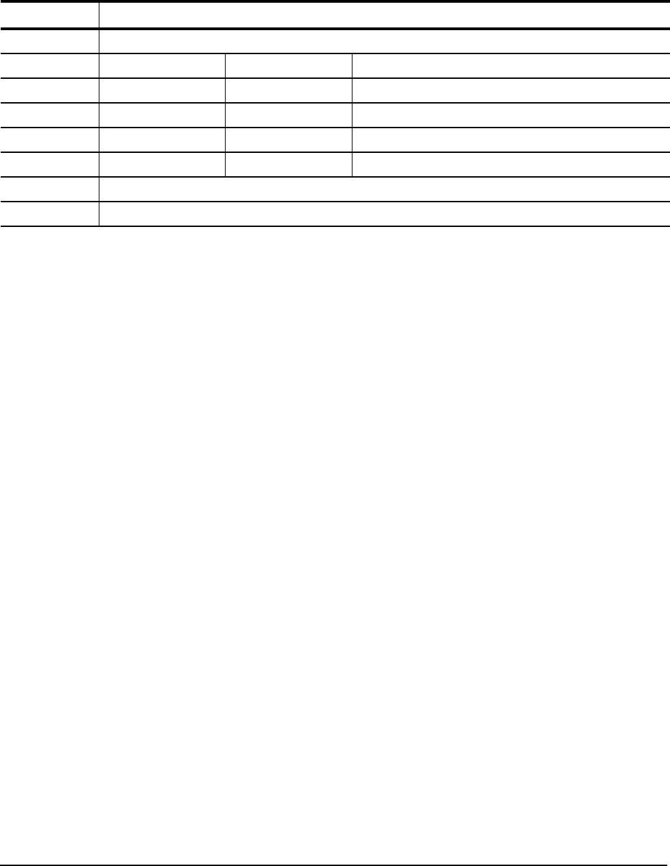
2.2 Formatted capacity
*One Gbyte equals one billion bytes when referring to hard drive capacity. Accessible capacity may vary depending on operating environment
and formatting.
2.2.1 LBA mode
When addressing these drives in LBA mode, all blocks (sectors) are consecutively numbered from 0 to n–1,
where n is the number of guaranteed sectors as defined above.
See Section 4.2.5, "Identify Device command" (words 60-61 and 100-103) for additional information about 48-
bit addressing support of drives with capacities over 137 Gbytes.
2.3 Default logical geometry
LBA mode
When addressing these drives in LBA mode, all blocks (sectors) are consecutively numbered from 0 to n–1,
where n is the number of guaranteed sectors as defined above.
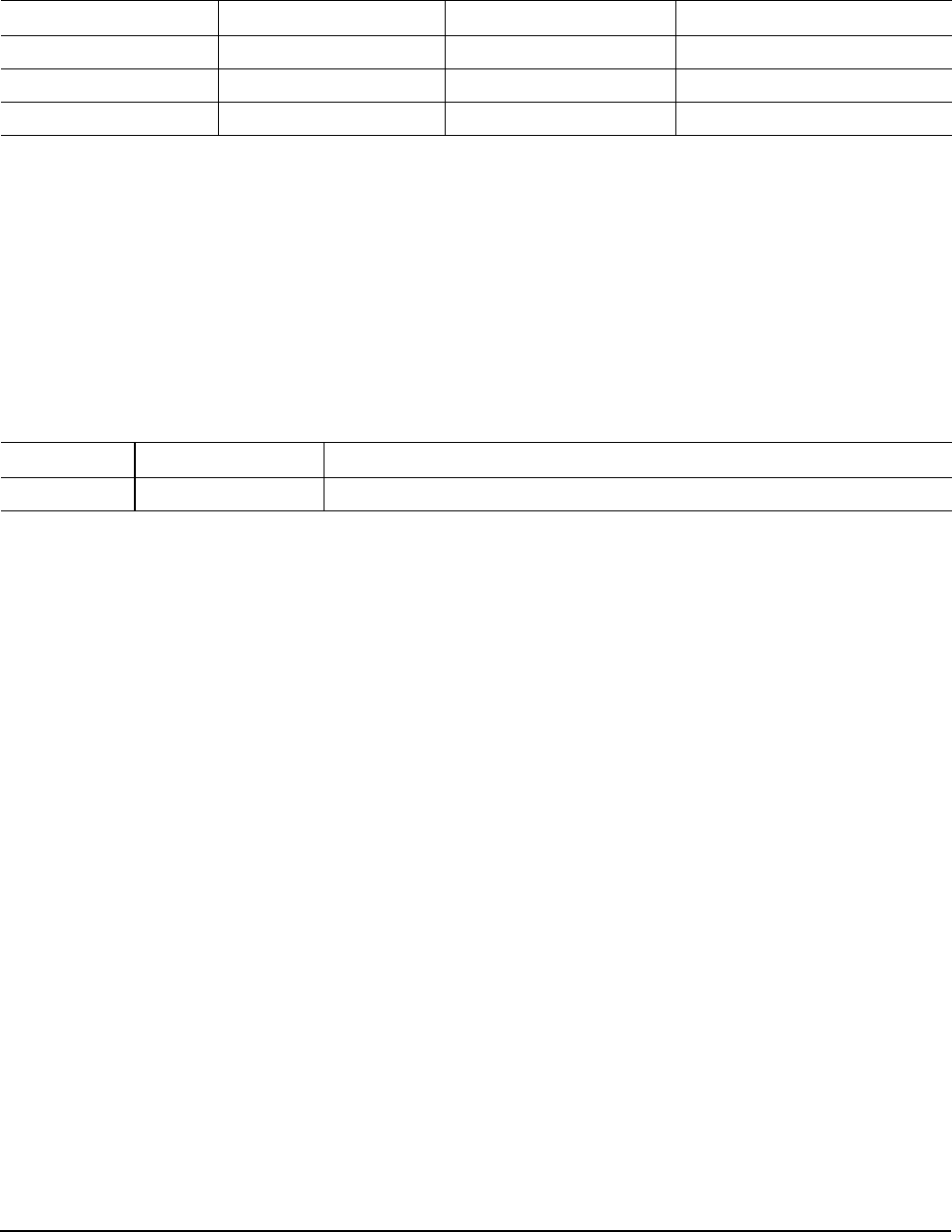
Model Formatted capacity* Guaranteed sectors Bytes per sector
ST9320322AS 320 Gbytes 625,142,448 512
ST9160312AS 160 Gbytes 312,581,808 512
ST9120312AS 120 Gbytes 234,441,648 512
Cylinders Read/write heads Sectors per track
16,383 16 63
8
Momentus 5400 FDE.3 SATA Product Manual, Rev. A
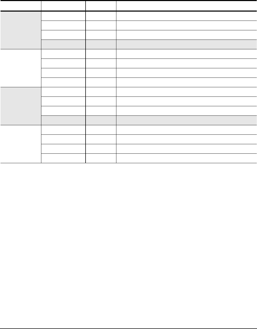
2.4 Physical organization
2.5 Recording and interface technology
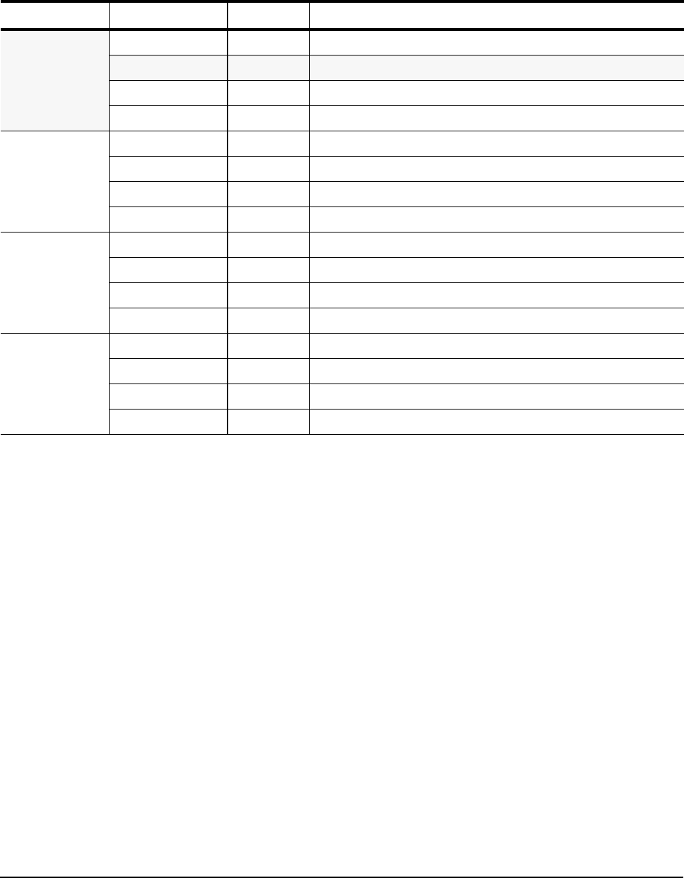
2.6 Physical characteristics
Drive model Read/write heads Number of discs
ST9320322AS 4 2
ST9160312AS 2 1
ST9120312AS 2 1
Interface Serial ATA (SATA)
Recording method Perpendicular
Recording density BPI (bits/inch max) 1,337k
Track density TPI (tracks/inch max) 191.5k
Areal density (Gbits/inch2 max) 253
Spindle speed (RPM) (± 0.2%) 5,400
Maximum Internal transfer rate (Mbits/sec) 830
I/O data-transfer rate (Gbits/sec max) 3.0
Interleave 1:1
Cache buffer 8 Mbytes (8,192 kbytes)
Drive specification
Height (mm)
(inches) 9.5 +/-0.2
0.374 +/-0.0078
Width (mm)
(inches) 69.85 +/-0.249
2.75 +/-0.0098
Length (mm)
(inches) 100.33 +/-0.25
3.95 +/-0.010
Typical weight
ST9320322AS
ST9160312AS
ST9120312AS
98 grams
0.212 pounds
93 grams
0.205 pounds
Momentus 5400 FDE.3 SATA Product Manual, Rev. A
9
2.7 Seek time
Seek measurements are taken with nominal power at 25°C ambient temperature. All times are measured using
drive diagnostics. The specifications in the table below are defined as follows:
• Track-to-track seek time is an average of all possible single-track seeks in both directions.
• Average seek time is a true statistical random average of at least 5,000 measurements of seeks between
random tracks, less overhead.
Note. These drives are designed to consistently meet the seek times represented in this manual. Physical
seeks, regardless of mode (such as track-to-track and average), are expected to meet the noted
values. However, due to the manner in which these drives are formatted, benchmark tests that
include command overhead or measure logical seeks may produce results that vary from these
specifications.
2.8 Start/stop times
Typical seek times (msec) Read
Track-to-track 1.5
Average 11.0
Full-stroke 24.0
Average latency 5.56
Time to ready Typical Max @ 25°C
Power-on to Ready (sec) 3.4 8.0
Standby to Ready (sec) 3.2 8.0
10
Momentus 5400 FDE.3 SATA Product Manual, Rev. A
2.9 Power specifications
The drive receives DC power (+5V) through a native SATA power connector.
2.9.1 Power consumption
Power requirements for the drives are listed in table 3. Typical power measurements are based on an average
of drives tested, under nominal conditions, at 25°C ambient temperature.
• Spinup power
Spinup power is measured from the time of power-on to the time that the drive spindle reaches operating speed.
• Seek mode
During seek mode, the read/write actuator arm moves toward a specific position on the disc surface and does
not execute a read or write operation. Servo electronics are active. Seek mode power is measured based on
three random seek operations every 100 msecs. This mode is not typical.
•Read/write power and current
Read/write power is measured with the heads on track, based on three 63 sector read or write operations
every 100 msecs.
• Idle mode power
Idle mode power is measured with the drive up to speed, with servo electronics active and with the heads in
a random track location.
• Standby mode
During Standby mode, the drive accepts commands, but the drive is not spinning, and the servo and read/
write electronics are in power-down model
*During periods of drive idle, some offline activity may occur according to the S.M.A.R.T. specification, which may increase acoustic and
power to operational levels.
Table 3: DC power
Power dissipation +5V input average (25° C)
Spinup (max) 1.0 amps
Seek 2.0 watts
Read 1.6 watts
Write 1.9 watts
Idle, performance* 1.6 watts
Idle, active* 0.8 watts
Idle, low power mode* 0.7 watts
Standby 0.24 watts
Sleep 0.24 watts
Momentus 5400 FDE.3 SATA Product Manual, Rev. A
11
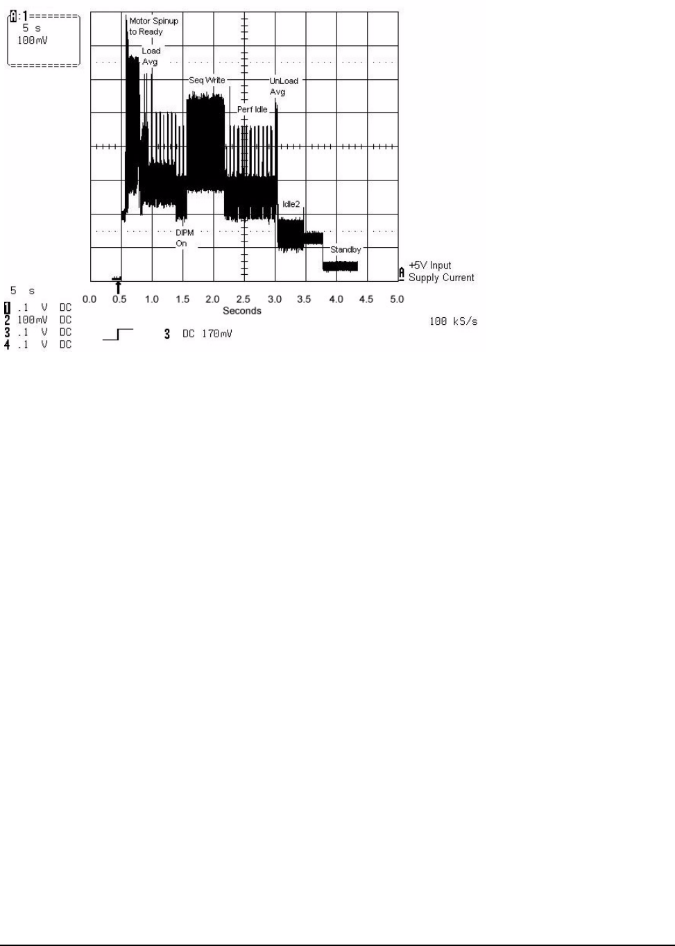
2.9.1.1 Typical current profile
Figure 1. Typical +5V only startup and operation current profile
2.9.2 Deferred spinup
Momentus 5400 FDE.3 SATA drives do not support the deferred spinup option. If you require this option, refer
to the Momentus 5400.3 SATA Blade Server family of drives.
2.9.3 Conducted noise
Input noise ripple is measured at the host system power supply across an equivalent 15-ohm resistive load on
the +5 volt line.
Using 5-volt power, the drive is expected to operate with a maximum of 100 mV peak-to-peak square-wave
injected noise at up to 10 MHz.
Note. Equivalent resistance is calculated by dividing the nominal voltage by the typical RMS read/write
current.
2.9.4 Voltage tolerance
Voltage tolerance (including noise):
5V ± 5%

12
Momentus 5400 FDE.3 SATA Product Manual, Rev. A
2.9.5 Power-management modes
The drive provides programmable power management to provide greater energy efficiency. In most systems,
you can control power management through the system setup program. The drive features the following
power-management modes:
• Active mode
The drive is in Active mode during the read/write and seek operations.
• Idle mode
The buffer remains enabled, and the drive accepts all commands and returns to Active mode any time disc
access is necessary.
• Standby mode
The drive enters Standby mode when the host sends a Standby Immediate command. If the host has set the
standby timer, the drive can also enter Standby mode automatically after the drive has been inactive for a
specifiable length of time. The standby timer delay is established using a Standby or Idle command. In Standby
mode, the drive buffer is in Self Refresh Low Power mode, the heads are parked and the spindle is at rest.
The drive accepts all commands and returns to Active mode any time disc access is necessary.
• Sleep mode
The drive enters Sleep mode after receiving a Sleep command from the host. In Sleep mode, the drive buffer
is in Self Refresh Low Power mode, the heads are parked and the spindle is at rest. The drive leaves Sleep
mode after it receives a Hard Reset or Soft Reset from the host. After receiving a reset, the drive exits Sleep
mode and enters Standby mode with all current translation parameters intact.
• Idle and Standby timers
Each time the drive performs an Active function (read, write or seek), the standby timer is reinitialized and
begins counting down from its specified delay times to zero. If the standby timer reaches zero before any
drive activity is required, the drive makes a transition to Standby mode. In both Idle and Standby mode, the
drive accepts all commands and returns to Active mode when disc access is necessary.
Table 4: Power management modes
Power modes Heads Spindle Buffer
Active (operating) Tracking Rotating Full power
Idle, performance Tracking Rotating Self refresh—low power
Idle, active Floating Rotating Self refresh—low power
Idle, low power Parked Rotating Self refresh—low power
Standby Parked Stopped Self refresh—low power
Sleep Parked Stopped Self refresh—low power
Momentus 5400 FDE.3 SATA Product Manual, Rev. A
13
2.10 Environmental specifications
2.10.1 Ambient temperature
Ambient temperature is defined as the temperature of the environment immediately surrounding the drive.
Actual drive case temperature should not exceed 65°C (149°F) within the operating ambient conditions.
Above 1,000 feet (305 meters), the maximum temperature is derated linearly by 1°C every 1000 feet.
2.10.2 Temperature gradient
2.10.3 Humidity
2.10.3.1 Relative humidity
2.10.3.2 Wet bulb temperature
2.10.4 Altitude
Operating 0° to 60°C (32° to 140°F)
Nonoperating –40° to 70°C (–40° to 158°F)
Operating 20°C per hour (68°F per hour max), without condensation
Nonoperating 35°C per hour (95°F per hour max), without condensation
Operating 5% to 95% noncondensing (30% per hour max)
Nonoperating 5% to 95% noncondensing (30% per hour max)
Operating 37.7°C (99.86°F max)
Nonoperating 40°C (104°F max)
Operating –60.96 m to 3,048 m (–200 ft to 10,000+ ft)
Nonoperating –304.8 m to 12,192 m (–1,000 ft to 40,000+ ft)
14
Momentus 5400 FDE.3 SATA Product Manual, Rev. A
2.10.5 Shock
All shock specifications assume that the drive is mounted securely with the input shock applied at the drive
mounting screws. Shock may be applied in the X, Y or Z axis.
2.10.5.1 Operating shock
These drives comply with the performance levels specified in this document when subjected to a maximum
operating shock of 350 Gs based on half-sine shock pulses of 2 msec. Shocks should not be repeated more
than two times per second.
2.10.5.2 Nonoperating shock
The nonoperating shock level that the drive can experience without incurring physical damage or degradation
in performance when subsequently put into operation is 800 Gs based on a nonrepetitive half-sine shock pulse
of 2 msec duration.
The nonoperating shock level that the drive can experience without incurring physical damage or degradation
in performance when subsequently put into operation is 1,000 Gs based on a nonrepetitive half-sine shock
pulse of 1 msec duration.
The nonoperating shock level that the drive can experience without incurring physical damage or degradation
in performance when subsequently put into operation is 600 Gs based on a nonrepetitive half-sine shock pulse
of 0.5 msec duration.
2.10.6 Vibration
All vibration specifications assume that the drive is mounted securely with the input vibration applied at the
drive mounting screws. Vibration may be applied in the X, Y or Z axis.
2.10.6.1 Operating vibration
The maximum vibration levels that the drive may experience while meeting the performance standards speci-
fied in this document are specified below.
2.10.6.2 Nonoperating vibration
The maximum nonoperating vibration levels that the drive may experience without incurring physical damage or degrada-
tion in performance when subsequently put into operation are specified below.
5–500 Hz 1.0 Gs (0 to peak). Max displacement may apply below 10 Hz.
5–500 Hz 5.0 Gs (0 to peak). Max displacement may apply below 22 Hz.
Momentus 5400 FDE.3 SATA Product Manual, Rev. A
15
2.11 Acoustics
Drive emission of sound is measured consistent with the ECMA-74 and its’ referenced standards. Testing is
conducted at room temperature (approximately 25°C). Emission levels are reported as the total A-weighted
sound power levels for steady state, idle, and active seek modes of operation.
*During periods of drive idle, some offline activity may occur according to the S.M.A.R.T. specification, which may increase acoustic and
power to operational levels.
Test for Prominent Discrete Tones (PDTs)
Seagate follows the ECMA-74 standards for measurement and identification of PDTs. An exception to this pro-
cess is the use of the absolute threshold of hearing. Seagate uses the lower limit for the threshold curve* to
discern tone audibility and to compensate for the inaudible components of sound prior to computation of tone
ratios according to Annex D of the ECMA-74 standards.
*Defined as the median curve given by ISO 389-7 (Tf curve) minus 10dB at all frequencies.
2.12 Electromagnetic immunity
When properly installed in a representative host system, the drive operates without errors or degradation in
performance when subjected to the radio frequency (RF) environments defined in the following table:
Idle* Performance seek
2.3 bels (typ)
2.5 bels (max) 2.6 bels (typ)
2.7 bels (max)
Test Description Performance
level Reference
standard
Electrostatic discharge Contact, HCP, VCP: ± 4 kV; Air: ± 8 kV B EN 61000-4-2: 95
Radiated RF immunity 80 to 2,000 MHz, 10 V/m,
80% AM with 1 kHz sine
900 MHz, 3 V/m, 50% pulse modulation @ 200 Hz
A EN 61000-4-3: 96
ENV 50204: 95
Electrical fast transient ± 1 kV on AC mains, ± 0.5 kV on external I/O B EN 61000-4-4: 95
Surge immunity ± 1 kV differential, ± 2 kV common, AC mains B EN 61000-4-5: 95
Conducted RF immunity 150 kHz to 80 MHz, 3 Vrms, 80% AM with 1 kHz
sine A EN 61000-4-6: 97
Power Frequency H-field
immunity 1 A/m, 50Hz/60Hz, 3 axes A EN 61000-4-8: 97
Voltage dips, interrupts 30% Reduction for 25 cycles
>95% Reduction for 250 cycles
>95%, 0.5 cycles
C
C
B
EN 61000-4-11: 94

16
Momentus 5400 FDE.3 SATA Product Manual, Rev. A
2.13 Reliability
2.14 Agency certification
2.14.1 Safety certification
The drives are recognized in accordance with UL 1950 and CSA C22.2 (950) and meet all applicable sections
of IEC950 and EN 60950 as tested by TUV North America.
2.14.2 Electromagnetic compatibility
Hard drives that display the CE mark comply with the European Union (EU) requirements specified in the Elec-
tromagnetic Compatibility Directive (89/336/EEC). Testing is performed to the levels specified by the product
standards for Information Technology Equipment (ITE). Emission levels are defined by EN 55022, Class B and
the immunity levels are defined by EN 55024.
Seagate uses an independent laboratory to confirm compliance with the EC directives specified in the previous
paragraph. Drives are tested in representative end-user systems. Although CE-marked Seagate drives comply
with the directives when used in the test systems, we cannot guarantee that all systems will comply with the
directives. The drive is designed for operation inside a properly designed enclosure, with properly shielded I/O
cable (if necessary) and terminators on all unused I/O ports. Computer manufacturers and system integrators
should confirm EMC compliance and provide CE marking for their products.
Measurement type Specification
Nonrecoverable read errors 1 per 1014 bits read, max.
Annualized Failure Rate (AFR) <0.48%
Load/Unload (U/UL)
25°C, 50% relative humidity
32°C, 80% relative humidity
5°C, 80% relative humidity
5°C, 10% relative humidity
55°C, 16% relative humidity
600,000 software-controlled power on/off cycles
20,000 hard power on/off cycles
600,000 software-controlled power on/off cycles
20,000 hard power on/off cycles
Warranty 5 years on distribution units.
Important: When returning a drive for warranty support, if possible, you should
provide the valid ATA Master password, or return the drive in the Security Erased
state with the User Data Area accessible.
If these recommendations are not followed, Seagate cannot access the drive to
perform failure analysis to verify your warranty claim.
To determine the warranty for a specific drive, use a web browser to access the
following web page:
www.seagate.com/support/service/
From this page, click on the “Verify Your Warranty” link. You will be asked to pro-
vide the drive serial number, model number (or part number) and country of pur-
chase. The system will display the warranty information for your drive.

Momentus 5400 FDE.3 SATA Product Manual, Rev. A
17
Korean RRL
If these drives have the Korea Ministry of Information and Communication (MIC) logo, they comply with para-
graph 1 of Article 11 of the Electromagnetic Compatibility control Regulation and meet the Electromagnetic
Compatibility (EMC) Framework requirements of the Radio Research Laboratory (RRL) Ministry of Information
and Communication Republic of Korea.
These drives have been tested and comply with the Electromagnetic Interference/Electromagnetic Susceptibil-
ity (EMI/EMS) for Class B products. Drives are tested in a representative, end-user system by a Korean-recog-
nized lab.
• Certificate number: STX-54005 (B)
• Trade name or applicant: Seagate TEchnology LLC
• Manufacturing date: March 18, 2008 (Date of Certification)
• Manufacturer/nationality: USA, Singapore and China
Australian C-Tick (N176)
If these models have the C-Tick marking, they comply with the Australia/New Zealand Standard AS/NZS3548
1995 and meet the Electromagnetic Compatibility (EMC) Framework requirements of the Australian Communi-
cation Authority (ACA).
2.14.3 FCC verification
These drives are intended to be contained solely within a personal computer or similar enclosure (not attached
as an external device). As such, each drive is considered to be a subassembly even when it is individually mar-
keted to the customer. As a subassembly, no Federal Communications Commission verification or certification
of the device is required.
Seagate Technology LLC has tested this device in enclosures as described above to ensure that the total
assembly (enclosure, disc drive, motherboard, power supply, etc.) does comply with the limits for a Class B
computing device, pursuant to Subpart J, Part 15 of the FCC rules. Operation with noncertified assemblies is
likely to result in interference to radio and television reception.
Radio and television interference. This equipment generates and uses radio frequency energy and if not
installed and used in strict accordance with the manufacturer’s instructions, may cause interference to radio
and television reception.
This equipment is designed to provide reasonable protection against such interference in a residential installa-
tion. However, there is no guarantee that interference will not occur in a particular installation. If this equipment
does cause interference to radio or television, which can be determined by turning the equipment on and off,
you are encouraged to try one or more of the following corrective measures:
• Reorient the receiving antenna.
• Move the device to one side or the other of the radio or TV.
• Move the device farther away from the radio or TV.
• Plug the computer into a different outlet so that the receiver and computer are on different branch outlets.
If necessary, you should consult your dealer or an experienced radio/television technician for additional sug-
gestions. You may find helpful the following booklet prepared by the Federal Communications Commission:
How to Identify and Resolve Radio-Television Interference Problems. This booklet is available from the Super-
intendent of Documents, U.S. Government Printing Office, Washington, DC 20402. Refer to publication num-
ber 004-000-00345-4.
18
Momentus 5400 FDE.3 SATA Product Manual, Rev. A
2.15 Environmental protection
Seagate designs its products to meet environmental protection requirements worldwide, including regulations
restricting certain chemical substances.
2.15.1 European Union Restriction of Hazardous Substances (RoHS)
Seagate designs its products to meet environmental protection requirements worldwide, including regulations
restricting certain chemical substances. A new law, the European Union Restriction of Hazardous Substances
(RoHS) Directive, restricts the presence of chemical substances, including Lead, Cadmium, Mercury, Hexava-
lent Chromium, PBB and PBDE, in electronic products, effective July 2006. This drive is manufactured with
components and materials that comply with the RoHS Directive.
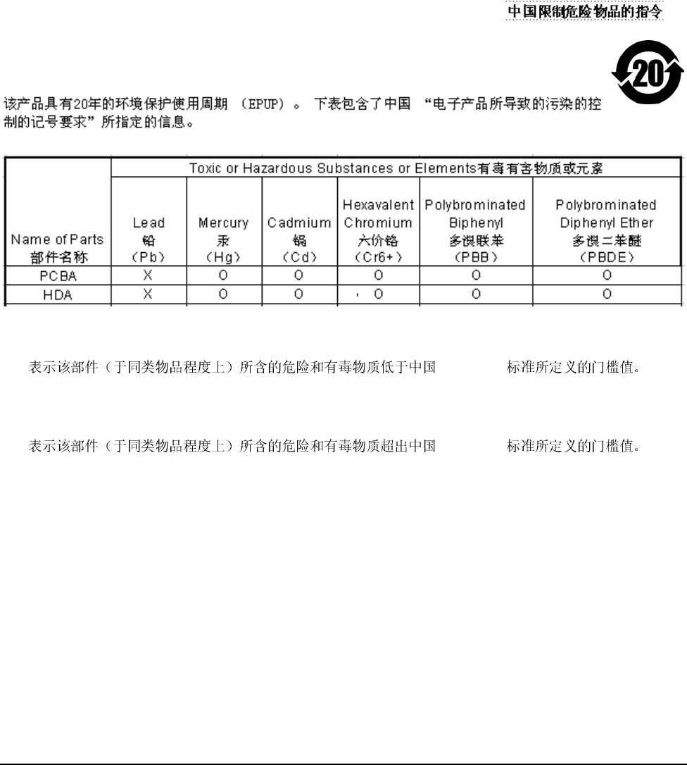
2.15.2 China Restriction of Hazardous Substances (RoHS) Directive
This product has an Environmental Protection Use Period (EPUP) of 20 years. The following
table contains information mandated by China's "Marking Requirements for Control of Pollution
Caused by Electronic Information Products" Standard.
"O" indicates the hazardous and toxic substance content of the part (at the homogenous material level) is lower
than the threshold defined by the China RoHS MCV Standard.
"X" indicates the hazardous and toxic substance content of the part (at the homogenous material level) is over
the threshold defined by the China RoHS MCV Standard.
2.16 Corrosive environment
Seagate electronic drive components pass accelerated corrosion testing equivalent to 10 years exposure to
light industrial environments containing sulfurous gases, chlorine and nitric oxide, classes G and H per ASTM
B845. However, this accelerated testing cannot duplicate every potential application environment.
Users should use caution exposing any electronic components to uncontrolled chemical pollutants and corro-
sive chemicals as electronic drive component reliability can be affected by the installation environment. The sil-
ver, copper, nickel and gold films used in Seagate products are especially sensitive to the presence of sulfide,
chloride, and nitrate contaminants. Sulfur is found to be the most damaging. In addition, electronic components
should never be exposed to condensing water on the surface of the printed circuit board assembly (PCBA) or
exposed to an ambient relative humidity greater than 95%. Materials used in cabinet fabrication, such as vulca-
nized rubber, that can outgas corrosive compounds should be minimized or eliminated. The useful life of any
electronic equipment may be extended by replacing materials near circuitry with sulfide-free alternatives.
“
O”RoHS MCV
“
X”RoHS MCV

Momentus 5400 FDE.3 SATA Product Manual, Rev. A
19
3.0 Configuring and mounting the drive
This section contains the specifications and instructions for configuring and mounting the drive.
Momentus® 5400 FDE.3 SATA drives may be connected to any computer system that supports a standard
SATA interface.
You can elect to use Momentus 5400 FDE.3 SATA drives in one of two different security modes:
1. The ATA Security mode
To operate in ATA Security mode, you only need a host system and operating system that supports the
existing ATA Security Command Set. The drive is shipped to operating in this mode, ready to use.
2. The DriveTrust Security mode
To enable a robust enterprise-level security and management policy, you may elect to operate in
DriveTrust Security mode. To do so, you will need to use a third-party security application to manage the
DriveTrust features. Please contact your system or software provider for more details.
Refer to Table 1 on page 2 to determine which mode is best for your particular solution.
Note. As with any disc drive, Seagate highly encourages consumers to consistently back up their data as
well as the security pre-boot password, user name, and domain name on another storage device.
Seagate is not responsible for lost or stolen authentication data such as passwords, user names,
domain names, or any authentication data perceived to be inoperative, and as a consequence of
lost or stolen passwords, user names, or domain names, Seagate cannot be held liable for data
that cannot be retrieved from the drive due to inability to authenticate the user to the drive as
required by the security pre-boot software.
3.1 Handling and static-discharge precautions
After unpacking, and before installation, the drive may be exposed to potential handling and electrostatic dis-
charge (ESD) hazards. Observe the following standard handling and static-discharge precautions:
Caution:
• Keep the drive in the electrostatic discharge (ESD) bag until you are ready for installation to limit the drive’s
exposure to ESD.
• Before handling the drive, put on a grounded wrist strap, or ground yourself frequently by touching the metal
chassis of a computer that is plugged into a grounded outlet. Wear a grounded wrist strap throughout the entire
installation procedure.
• Handle the drive only by its edges or frame.
• The drive is fragile—handle it with care. Do not press down on the drive top cover.
• Always rest the drive on a padded, antistatic surface until you mount it in the computer.
• Do not touch the connector pins or the printed circuit board.
• Do not remove the factory-installed labels from the drive or cover them with additional labels. Removal voids
the warranty. Some factory-installed labels contain information needed to service the drive. Other labels are
used to seal out dirt and contamination.
20
Momentus 5400 FDE.3 SATA Product Manual, Rev. A
• Do not obstruct the breather hole located on the top cover of the drive. Refer to Figure 4 for the exact location
of this hole.
3.2 Configuring the drive
Each drive on the Serial ATA interface connects in a point-to-point configuration with the Serial ATA host
adapter. There is no master/slave relationship because each drive is considered a master in a point-to-point
relationships. If two drives are attached on one Serial ATA host adapter, the host operating system views the
two devices as if they were both “masters” on two separate ports. This means both drives behave as if they are
Device 0 (master) devices.
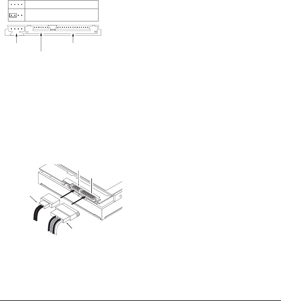
Serial ATA drives are designed for easy installation with no jumpers, terminators, or other settings. It is not nec-
essary to set any jumpers on this drive for proper operation. The jumper block adjacent to the signal connector
is for factory use only.
Figure 2. Serial ATA connectors
3.3 Serial ATA cables and connectors
The Serial ATA interface cable consists of four conductors in two differential pairs, plus three ground connec-
tions. The cable size may be 30 to 26 AWG with a maximum length of one meter (39.37 inches). See Table 5
for connector pin definitions. Either end of the SATA signal cable can be attached to the drive or host.
For direct backplane connection, the drive connectors are inserted directly into the host receptacle. The drive
and the host receptacle incorporate features that enable the direct connection to be hot pluggable and blind
mateable.
For installations which require cables, you can connect the drive as illustrated in Figure 3.
Figure 3. Attaching SATA cabling
Each cable is keyed to ensure correct orientation.
Jumper block
SATA interface connector
SATA power connector
Limit data transfer rate to
1.5 Gbits per second
3.0 Gbits per second operation
Power cable
S
ATA interface cable
SATA interface connecto
r
Power connecto
r
Momentus 5400 FDE.3 SATA Product Manual, Rev. A
21
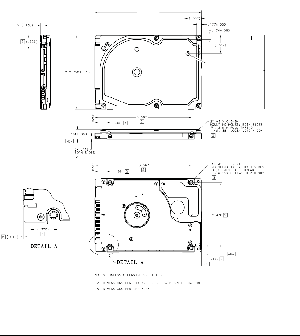
3.4 Drive mounting
You can mount the drive using four screws in the side-mounting holes or four screws in the bottom-mounting
holes. See Figure 4 for drive mounting dimensions. Follow these important mounting precautions when mount-
ing the drive:
• Allow a minimum clearance of 0.030 inches (0.76 mm) around the entire perimeter of the drive for cooling.
• Use only M3 UNC mounting screws.
• Do not overtighten the mounting screws. Maximum torque: 4.0 inch-lb (0.4519 N-m).
• Four (4) threads (0.080 inches, 2.032 mm) minimum screw engagement recommended.
• Avoid excessive drive distortion when mounting.
Measurements shown in Figure 4 are in inches.
Figure 4. Mounting dimensions
+Recommended
case temperature
measurement
location
Breather Hole
Do not cover
or seal.
3.95 +/- .010
22
Momentus 5400 FDE.3 SATA Product Manual, Rev. A
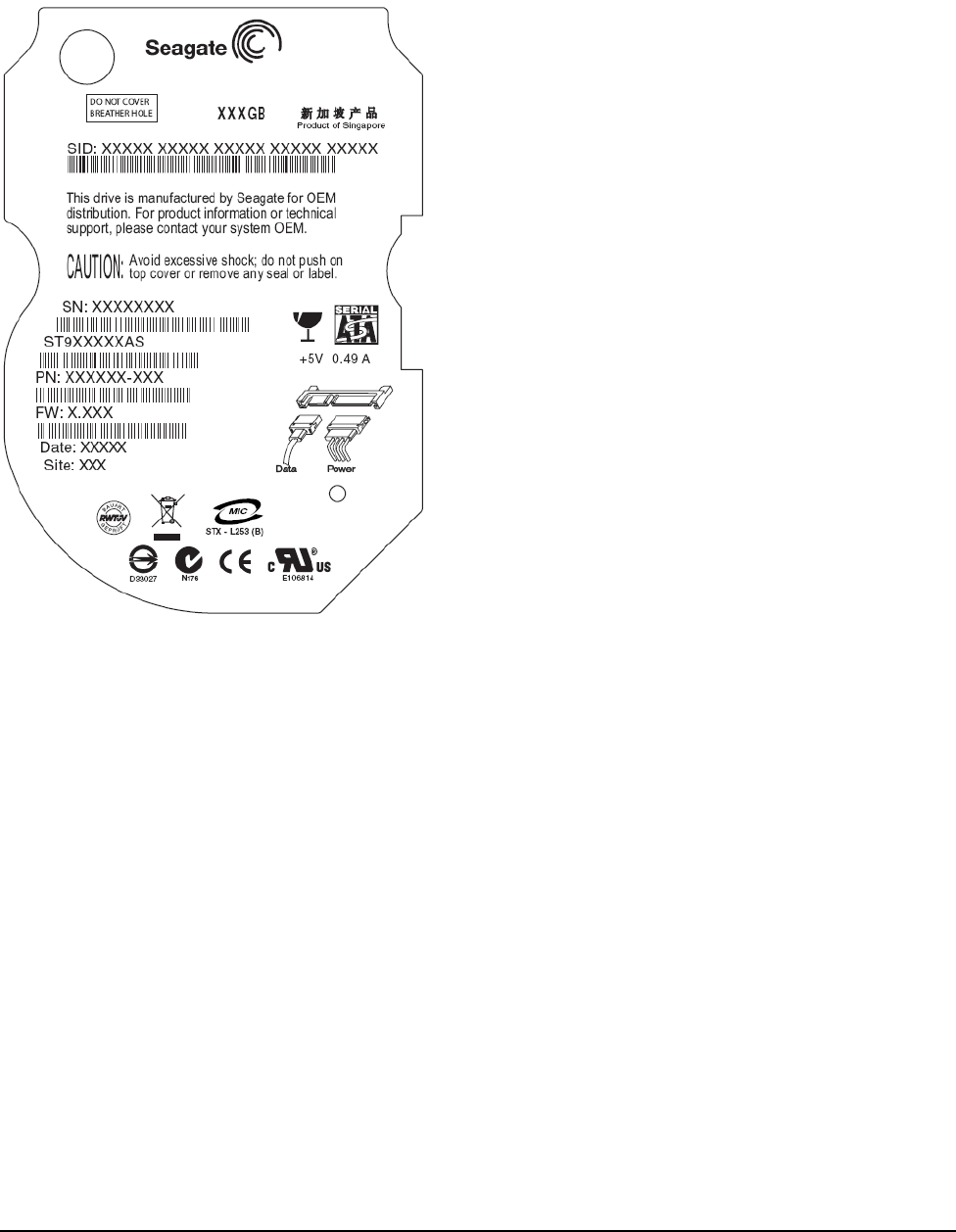
3.5 Drive integration
Momentus 5400 FDE.3 SATA drives may be installed in the target computer system in exactly the same way as
a non-FDE Momentus drive.
.
Figure 5. Momentus 5400 FDE.3 SATA drive label example
To install the drive in the system:
1. Remove the drive from the packaging material.
2. Install the drive in the computer system.
3. Load any desired images and operating system to the drive.
4. Install other components and options.
5. Set the original Master Password to a new value (see Section 1.2.1 for information about setting the SID)
utilizing System/BIOS or third party software (optional).
No password is required to change the Master password when the drive is in the unlocked state.
The drive remains in the unlocked state until a User password is set.
After the installation procedure is complete, the computer is ready to be shipped to the customer.
Note. The manufacturer of the computer system (system integrator) does not have to enter any password.
The installation procedure for the Momentus 5400 FDE.3 SATA is exactly the same as the Momentus
5400.5 SATA.

Momentus 5400 FDE.3 SATA Product Manual, Rev. A
23
3.5.1 Drive installation
Upon receipt by the consumer, the drive’s user interface is identical to a Momentus 5400.5 drive. The normal
ATA security commands are functioning and available for initialization of the password as follows:
Per normal ATA Security Commands specifications, the drive is unlocked and all ATA security commands and
all normal ATA commands may be issued.
1. Consumer accesses the computer manufacturer’s BIOS set-up screen.
2. Consumer selects option to set User Password.
After setting the User password, the drive is now under access control (locked) and will require a password
for future accesses.
3. Optional: Consumer selects the option to set the Master password from the BIOS choices.
4. Consumer exits the BIOS settings menu and continues with the boot process.
5. The BIOS enters the Security Freeze Command (F5) prior to exiting the boot sequence.
3.5.2 Consumer usage
After initialization, the consumer will just need to enter their User password each time the computer is booted
according to the following description:
1. The computer system is turned on or the hardware is reset.
2. The drive reports to the BIOS that it is in the locked state per standard ATA Security Command reporting.
3. The BIOS queries the user for the password.
4. The BIOS supplies the password to the drive using the Security Unlock Command (F2).
5. The drive is unlocked and the BIOS may continue the booting process.
6. The BIOS enters the Security Freeze Lock Command (F5) prior to exiting the boot sequence.
Note. To ensure that the system reauthenticates the user, turn the laptop power off (shut down) rather
than putting it in sleep mode. The system will authenticate the user at powerup.
3.6 Security Erase--ATA security commands
The Momentus 5400 FDE.3 SATA provides powerful features for cryptographically erasing the drive for dis-
posal or repurposing. The drive uses the ATA Security Erase Prepare (F3) and ATA Security Erase (F4) com-
mands to perform the cryptographic erase.
3.6.1 Secure Erase procedure
Using the Security Erase commands, the drive's cryptographic key can be replaced according to the following
procedure:
1. Consumer boots up the computer normally according to the Consumer Usage section above.
2. Consumer invokes software or BIOS option for Erase.
3. The software or BIOS queries the user for either the User or Master password.
4. The software or BIOS issues the Security Erase Prepare (F3) command.
5. The software or BIOS issues the Security Erase Unit (F4) command.
Select the Enhanced erase for cryptographic key erasure that completes in less than one second.

24
Momentus 5400 FDE.3 SATA Product Manual, Rev. A
3.6.2 Drive State after Secure Erase
Upon completion of the erase sequence, the existing cryptographic key is erased, rendering all existing data
unintelligible, and the drive has been returned to the manufactured state as follows:
• The existing encryption key is deleted.
• A new random encryption key has been created on the drive.
• Encryption function is active and functioning.
The new key is used to encrypt all user data on write and decrypt on read.
• The user interface to the drive is active and all read and write commands are allowed.
• The ATA User password is reset to null (no value).
• The ATA Master password is not modified
The ATA Master password is the same value as it was before the erase.
• The ATA Security is set to the Unlocked state.
No password is required to access the drive.
The drive may now be disposed of safely, or the drive may be returned to service for another consumer follow-
ing the initialization procedure defined above. Drives returned to Seagate for warranty purposes have special
requirements. See the warranty information in Section 2.13 for additional details.
Momentus 5400 FDE.3 SATA Product Manual, Rev. A
25
4.0 Serial ATA interface
These drives use the industry-standard Serial ATA (SATA) interface that supports FIS data transfers. It sup-
ports ATA programmed input/output (PIO) modes 0–4; multiword DMA modes 0–2, and Ultra DMA modes 0–6.
The drive also supports the use of the IORDY signal to provide reliable high-speed data transfers.
For detailed information about the Serial ATA interface, refer to the “Serial ATA: High Speed Serialized AT
Attachment” specification.
4.1 Hot-Plug compatibility
Momentus 5400 FDE.3 SATA drives incorporate connectors which enable you to hot plug these drives in
accordance with the Serial ATA: High Speed Serialized AT Attachment specification revision 2.0. This specifi-
cation can be downloaded from http://www.serialata.org. This device requires a COMRESET from the host
after a hotplug event.
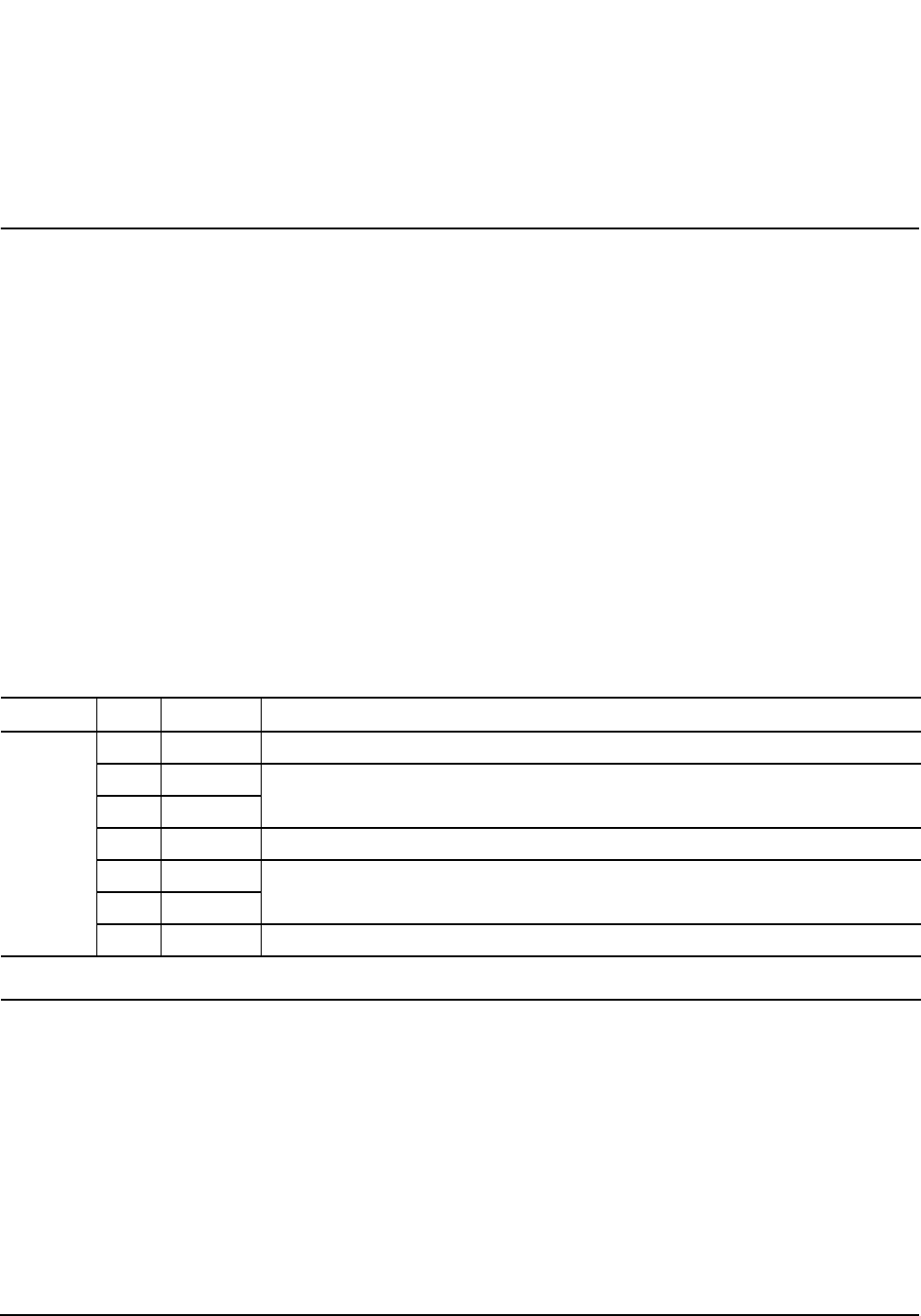
4.2 Serial ATA device plug connector pin definitions
Table 5 summarizes the signals on the Serial ATA interface and power connectors..
Table 5: Serial ATA connector pin definitions
Segment Pin Function Definition
Signal
S1 Ground 2nd mate
S2 A+ Differential signal pair A from Phy
S3 A-
S4 Ground 2nd mate
S5 B- Differential signal pair B from Phy
S6 B+
S7 Ground 2nd mate
Key and spacing separate signal and power segments
26
Momentus 5400 FDE.3 SATA Product Manual, Rev. A
Notes:
1. All pins are in a single row, with a 1.27 mm (0.050”) pitch.
2. The comments on the mating sequence apply to the case of backplane blindmate connector only. In this
case, the mating sequences are:
• the ground pins P4 and P12.
• the pre-charge power pins and the other ground pins.
• the signal pins and the rest of the power pins.
3. There are three power pins for each voltage. One pin from each voltage is used for pre-charge when
installed in a blind-mate backplane configuration.
4. All used voltage pins (Vx) must be terminated.
4.2.1 ATA Security policy exceptions
In the ATA Security Interface mode, the drive conforms to the ATA Security Policy, except the following desir-
able exceptions to implement the desired Momentus 5400 FDE.3 SATA behavior:
Upon execution of the secure erase sequence, the drive will have the following behavior:
• All secure erase modes will instantaneously delete the encryption key rendering all user data unintelligible.
• A new encryption key will be generated inside the drive replacing the previous encryption key.
• The new encryption/decryption key will be applied to the data for all subsequent writes/reads prior to the
next secure erase sequence.
• The user password will be cleared to a null value.
• The master password will retain the current value per the ATA specification.
Note. On completion of this sequence, the user is assured that all sectors on the drive are unintelligible and
Power
P1 V33 3.3V power
P2 V33 3.3V power
P3 V33 3.3V power, pre-charge, 2nd mate
P4 Ground 1st mate
P5 Ground 2nd mate
P6 Ground 2nd mate
P7 V55V power, pre-charge, 2nd mate
P8 V55V power
P9 V55V power
P10 Ground 2nd mate
P11 Reserved The pin corresponding to P11 in the backplane receptacle connector is also reserved
The corresponding pin to be mated with P11 in the power cable receptacle connector
shall always be grounded
P12 Ground 1st mate.
P13 V12 12V power, pre-charge, 2nd mate
P14 V12 12V power
P15 V12 12V power
Table 5: Serial ATA connector pin definitions
Segment Pin Function Definition
Momentus 5400 FDE.3 SATA Product Manual, Rev. A
27
the drive is returned to the default factory state. It is then immediately ready for disposal or repurpos-
ing.
The ATA Security Erase Unit Command provides for normal and enhanced erase modes as follows:
Choosing enhanced erase mode will simply perform the cryptographic erase described above, and return sta-
tus almost immediately. This is the recommended option.
To maintain consistency with the ATA Security specification, Momentus 5400 FDE.3 SATA drives provide an
option to perform the Normal Erase mode.
Choosing normal erase will result in the drive performing the cryptographic erase which is the same as choos-
ing enhanced erase.
Table 6: ATA Security Erase Unit bits
Word Content
0 Control word
Bit 0 Identifier 0 = Compare User password
1 = Compare Master password
Bit 1 Erase mode 0 = Normal Erase
1 = Enhanced Erase
Bit (15:2) Reserved
1 - 16 Password (32 bytes)
17 - 255 Reserved
28
Momentus 5400 FDE.3 SATA Product Manual, Rev. A
4.2.2 DriveTrust Mode support
Identify Page - Word 150 decimal (0x96h)- Bit 12 Identifies DriveTrust Support.
Value = 1 = DriveTrust is supported
Table 7: DriveTrust Identify Page
Ident Value BIT set Bit Description
5
0 15 Vendor specific
1 14 Vendor specific
0 13 Vendor specific
112 DriveTrust Enabled
0
0 11 Vendor specific
0 10 Vendor specific
0 9 Vendor specific
0 8 Vendor specific
9
1 7 Vendor specific
0 6 Vendor specific
0 5 Vendor specific
1 4 DriveTrust Supported
8
1 3 Vendor specific
0 2 Vendor specific
0 1 Vendor specific
0 0 Vendor specific
Momentus 5400 FDE.3 SATA Product Manual, Rev. A
29
4.2.3 Full Disc Encryption support
Identify Page--Word 243 decimal (0xF3h)--bit 14 indicates Full Disc Encryption capability.
1 = Full Disc Encryption supported.
Table 8: Full Disc Encryption Identify Page
Ident Value BIT set Bit Description
4
0 15 Vendor specific
114 Full Disc Encryption
0 13 Vendor specific
0 12 Vendor specific
0
0 11 Vendor specific
0 10 Vendor specific
0 9 Vendor specific
0 8 Vendor specific
0
0 7 Vendor specific
0 6 Vendor specific
0 5 Vendor specific
0 4 Vendor specific
0
0 3 Vendor specific
0 2 Vendor specific
0 1 Vendor specific
0 0 Vendor specific

30
Momentus 5400 FDE.3 SATA Product Manual, Rev. A
4.2.4 Supported ATA commands
The following table lists ATA-standard commands that the drive supports. For a detailed description of the ATA
commands, refer to the Serial ATA: High Speed Serialized AT Attachment specification. See “S.M.A.R.T. com-
mands” on page 38 for details and subcommands used in the S.M.A.R.T. implementation.
Table 9: Supported commands
ATA Security API DriveTrust Security API
Op
Code Command Locked Unlocked Frozen Secure
State Authenticated
State
Special Commands
5C TRUSTED RECEIVE (PIO) Executable Executable Executable Executable Executable
5D TRUSTED RECEIVE DMA Executable Executable Executable Executable Executable
5E TRUSTED SEND (PIO) Executable Executable Executable Executable Executable
5F TRUSTED SEND DMA Executable Executable Executable Executable Executable
Normal Commands
E5 CHECK POWER MODE Executable Executable Executable Executable Executable
98 CHECK POWER MODE Executable Executable Executable Executable Executable
51 CONFIGURE STREAM Aborted Executable Executable Aborted Executable
B1 DEVICE CONFIGURATION Aborted Executable Executable Aborted Executable
08 DEVICE RESET Executable Executable Executable Executable Executable
92 DOWNLOAD MICROCODE Aborted Aborted Aborted Aborted Aborted
90 EXECUTE DEVICE
DIAGNOSTIC Executable Executable Executable Executable Executable
E7 FLUSH CACHE Aborted Executable Executable Aborted Executable
EA FLUSH CACHE EXT Aborted Executable Executable Aborted Executable
EC IDENTIFY DEVICE Executable Executable Executable Executable Executable
A1 IDENTIFY PACKET
DEVICE Executable Executable Executable Executable Executable
E3 IDLE Executable Executable Executable Executable Executable
97 IDLE Executable Executable Executable Executable Executable
E1 IDLE IMMEDIATE Executable Executable Executable Executable Executable
95 IDLE IMMEDIATE Executable Executable Executable Executable Executable
00 NOP Executable Executable Executable Executable Executable
E4 READ BUFFER Aborted Executable Executable Aborted Executable
C8 READ DMA Aborted Executable Executable Aborted Executable
C9 READ DMA Aborted Executable Executable Aborted Executable
25 READ DMA EXT Aborted Executable Executable Aborted Executable

Momentus 5400 FDE.3 SATA Product Manual, Rev. A
31
2F READ LOG EXT Executable Executable Executable Executable Executable
C4 READ MULTIPLE Aborted Executable Executable Aborted Executable
29 READ MULTIPLE EXT Aborted Executable Executable Aborted Executable
F8 READ NATIVE MAX
ADDRESS Executable Executable Executable Executable Executable
27 READ NATIVE MAX
ADDRESS EXT Executable Executable Executable Executable Executable
20 READ SECTOR(S) Aborted Executable Executable Aborted Executable
21 READ SECTOR(S) Aborted Executable Executable Aborted Executable
24 READ SECTOR(S) EXT Aborted Executable Executable Aborted Executable
2A READ STREAM DMA EXT Aborted Executable Executable Aborted Executable
2B READ STREAM EXT Aborted Executable Executable Aborted Executable
40 READ VERIFY SECTOR(S) Aborted Executable Executable Aborted Executable
41 READ VERIFY SECTOR(S) Aborted Executable Executable Aborted Executable
42 READ VERIFY SECTOR(S)
EXT Aborted Executable Executable Aborted Executable
10 RECALIBRATE Executable Executable Executable Executable Executable
F6 SECURITY DISABLE
PASSWORD Aborted Executable Aborted Aborted Aborted
F3 SECURITY ERASE
PREPARE Executable Executable Aborted Aborted Aborted
F4 SECURITY ERASE UNIT Executable Executable Aborted Aborted Aborted
F5 SECURITY FREEZE LOCK Aborted Executable Executable Aborted Executable
F1 SECURITY SET PASS-
WORD Aborted Executable Aborted Aborted Aborted
F2 SECURITY UNLOCK Executable Executable Aborted Executable Executable
70 SEEK Executable Executable Executable Executable Executable
91 SET DRIVE PARAMETERS Executable Executable Executable Executable Executable
EF SET FEATURES Executable Executable Executable Executable Executable
F9HSET MAX ADDRESS Aborted Executable Executable Aborted Executable
F9H / 00HSET MAX ADDRESS EXT Aborted Executable Executable Aborted Executable
F9H / 01HSET MAX SET
PASSWORD Aborted Executable Executable Aborted Executable
F9H / 02HSET MAX LOCK Aborted Executable Executable Aborted Executable
Table 9: Supported commands
ATA Security API DriveTrust Security API
Op
Code Command Locked Unlocked Frozen Secure
State Authenticated
State

32
Momentus 5400 FDE.3 SATA Product Manual, Rev. A
F9H / 04HSET MAX FREEZE LOCK Aborted Executable Executable Aborted Executable
F9H / 03HSET MAX UNLOCK Aborted Executable Executable Aborted Executable
C6 SET MULTIPLE MODE Executable Executable Executable Executable Executable
E6 SLEEP Executable Executable Executable Executable Executable
99 SLEEP Executable Executable Executable Executable Executable
B0H / D9HSMART DISABLE
OPERATIONS Executable Executable Executable Executable Executable
B0H / D2HSMART ENABLE/DISABLE
AUTOSAVE Executable Executable Executable Executable Executable
B0H / D8HSMART ENABLE
OPERATIONS Executable Executable Executable Executable Executable
B0H / D4HSMART EXECUTE
OFF-LINE
IMMEDIATE
Executable Executable Executable Executable Executable
B0H / 08HSMART READ DATA Executable Executable Executable Executable Executable
B0H / D5HSMART READ LOG Executable Executable Executable Executable Executable
B0H / DAHSMART RETURN STATUS Executable Executable Executable Executable Executable
B0H / D6HSMART WRITE LOG Executable Executable Executable Executable Executable
E2 STANDBY Executable Executable Executable Executable Executable
96 STANDBY Executable Executable Executable Executable Executable
E0 STANDBY IMMEDIATE Executable Executable Executable Executable Executable
94 STANDBY IMMEDIATE Executable Executable Executable Executable Executable
E8 WRITE BUFFER Aborted Executable Executable Aborted Executable
CA WRITE DMA Aborted Executable Executable Aborted Executable
CB WRITE DMA Aborted Executable Executable Aborted Executable
35 WRITE DMA EXT Aborted Executable Executable Aborted Executable
3D WRITE DMA FUA EXT Aborted Executable Executable Aborted Executable
3F WRITE LOG EXT Aborted Executable Executable Aborted Executable
C5 WRITE MULTIPLE Aborted Executable Executable Aborted Executable
39 WRITE MULTIPLE EXT Aborted Executable Executable Aborted Executable
30 WRITE SECTOR(S) Aborted Executable Executable Aborted Executable
31 WRITE SECTOR(S) Aborted Executable Executable Aborted Executable
34 WRITE SECTOR(S) EXT Aborted Executable Executable Aborted Executable
Table 9: Supported commands
ATA Security API DriveTrust Security API
Op
Code Command Locked Unlocked Frozen Secure
State Authenticated
State

Momentus 5400 FDE.3 SATA Product Manual, Rev. A
33
3A WRITE STREAM DMA EXT Aborted Executable Executable Aborted Executable
3B WRITE STREAM EXT Aborted Executable Executable Aborted Executable
Table 9: Supported commands
ATA Security API DriveTrust Security API
Op
Code Command Locked Unlocked Frozen Secure
State Authenticated
State

34
Momentus 5400 FDE.3 SATA Product Manual, Rev. A
4.2.5 Identify Device command
The Identify Device command (command code ECH) transfers information about the drive to the host following
power up. The data is organized as a single 512-byte block of data, whose contents are shown in the table
below. All reserved bits or words should be set to zero. Parameters listed with an “x” are drive-specific or vary
with the state of the drive.
The following commands contain drive-specific features that may not be included in the Serial ATA specifica-
tion.
Word Description Value
0
Configuration information:
• Bit 15: 0 = ATA; 1 = ATAPI
• Bit 7: removable media
• Bit 6: removable controller
• Bit 0: reserved
0C5AH
1 Number of logical cylinders 16,383
2 ATA-reserved 0000H
3 Number of logical heads 16
4 Retired 0000H
5 Retired 0000H
6 Number of logical sectors per logical track: 63 003FH
7–9 Retired 0000H
10–19 Serial number: (20 ASCII characters, 0000H = none) ASCII
20 Retired 0000H
21 Retired 0400H
22 Obsolete 0000H
23–26 Firmware revision (8 ASCII character string, padded with
blanks to end of string) x.xx
27–46 Drive model number: (40 ASCII characters, padded with
blanks to end of string) ST9320322AS
ST9160312AS
ST9120312AS
47 (Bits 7–0) Maximum sectors per interrupt on Read multiple
and Write multiple (16) 8001H
48 Reserved 0000H
49 Standard Standby timer, IORDY supported and may be dis-
abled 2F00H
50 ATA-reserved 0000H
51 PIO data-transfer cycle timing mode 0200H
52 Retired 0200H
53 Words 54–58, 64–70 and 88 are valid 0007H
54 Number of current logical cylinders xxxxH
55 Number of current logical heads xxxxH
56 Number of current logical sectors per logical track xxxxH

Momentus 5400 FDE.3 SATA Product Manual, Rev. A
35
57–58 Current capacity in sectors xxxxH
59 Number of sectors transferred during a Read Multiple or
Write Multiple command xxxxH
60–61 Total number of user-addressable LBA sectors. This field
contains a value that is one greater than the total number of
user-addressable sectors. The maximum value that shall be
placed in this field is 0FFFFFFh. The 0FFFFFFFh value
applies to all capacities over 137 Gbytes (see Section 2.2
and 2.3 for related information).
ST9320322AS = 0FFFFFFFh
ST9160312AS = 0FFFFFFFh
ST9120312AS = 234,441,648
62 Retired 0000H
63 Multiword DMA active and modes supported
(see note following this table) xx07H
64 Advanced PIO modes supported (modes 3 and 4 supported) 0003H
65 Minimum multiword DMA transfer cycle time per word
(120 nsec) 0078H
66 Recommended multiword DMA transfer cycle time per word
(120 nsec) 0078H
67 Minimum PIO cycle time without IORDY flow control
(240 nsec) 00F0H
68 Minimum PIO cycle time with IORDY flow control (120 nsec) 0078H
69–74 ATA-reserved 0000H
75 Queue depth 0000H
76 Serial ATA capabilities 0508H
77 ATA-reserved 0000H
78 Serial ATA features supported 0048H
79 Serial ATA features enabled 0040H
80 Major version number 003EH
81 Minor version number 0000H
82 Command sets supported 346BH
83 Command sets supported 7D09H
84 Command sets support extension 61E3H
85 Command sets enabled 34xxH
86 Command sets enabled BC09H
87 Command sets enable extension 61E3H
88 Ultra DMA support and current mode
(see note following this table) xx7FH
89 Security erase time 0001H
90 Enhanced security erase time 0001H
92 Master password revision code FFFEH
Word Description Value
36
Momentus 5400 FDE.3 SATA Product Manual, Rev. A
93 Hardware reset value
(see description following this table) xxxxH
94 Auto acoustic management setting xxxxH
95–99 ATA-reserved 0000H
100–
103 Total number of user-addressable LBA sectors available
(see Section 2.2 for related information)
These words are required for drives that support the 48-bit
addressing feature. Maximum value: 0000FFFFFFFFFFFFh.
ST9320322AS = 625,142,448
ST9160312AS = 312,581,808
ST9120312AS = 234,441,648
104–
127 ATA-reserved 0000H
128 Security status 0021H
129–
159 Seagate-reserved xxxxH
160–
254 ATA-reserved 0000H
255 Integrity word xxA5H
Note. See the bit descriptions below for words 63, 88, 93 and 94 of the Identify Drive data:
Description (if bit is set to 1)
Bit Word 63
0Multiword DMA mode 0 is supported.
1Multiword DMA mode 1 is supported.
2Multiword DMA mode 2 is supported.
8Multiword DMA mode 0 is currently active.
9Multiword DMA mode 1 is currently active.
10 Multiword DMA mode 2 is currently active.
Bit Word 88
0Ultra DMA mode 0 is supported.
1Ultra DMA mode 1 is supported.
2Ultra DMA mode 2 is supported.
3Ultra DMA mode 3 is supported.
4Ultra DMA mode 4 is supported.
8Ultra DMA mode 0 is currently active.
9Ultra DMA mode 1 is currently active.
10 Ultra DMA mode 2 is currently active.
11 Ultra DMA mode 3 is currently active.
12 Ultra DMA mode 4 is currently active.
13 Ultra DMA mode 5 is currently active.
Bit Word 93
13 1 = 80-conductor cable detected, CBLID above VIH
0 = 40-conductor cable detected, CBLID below VIL
Word Description Value

Momentus 5400 FDE.3 SATA Product Manual, Rev. A
37
4.2.6 Set Features command
This command controls the implementation of various features that the drive supports. When the drive receives
this command, it sets BSY, checks the contents of the Features register, clears BSY and generates an inter-
rupt. If the value in the register does not represent a feature that the drive supports, the command is aborted.
Power-on default has the read look-ahead and write caching features enabled. The acceptable values for the
Features register are defined as follows:
Note. At power-on, or after a hardware or software reset, the default values of the features are as indi-
cated above.
Table 10: Set Features command values
02HEnable write cache (default).
03HSet transfer mode (based on value in Sector Count register).
Sector Count register values:
00HSet PIO mode to default (PIO mode 2).
01HSet PIO mode to default and disable IORDY (PIO mode 2).
08HPIO mode 0
09HPIO mode 1
0AHPIO mode 2
0BHPIO mode 3
0CHPIO mode 4 (default)
20HMultiword DMA mode 0
21HMultiword DMA mode 1
22HMultiword DMA mode 2
40HUltra DMA mode 0
41HUltra DMA mode 1
42HUltra DMA mode 2
43HUltra DMA mode 3
44HUltra DMA mode 4
45HUltra DMA mode 5
46HUltra DMA mode 6
55HDisable read look-ahead (read cache) feature.
82HDisable write cache
AAHEnable read look-ahead (read cache) feature (default).
F1HReport full capacity available
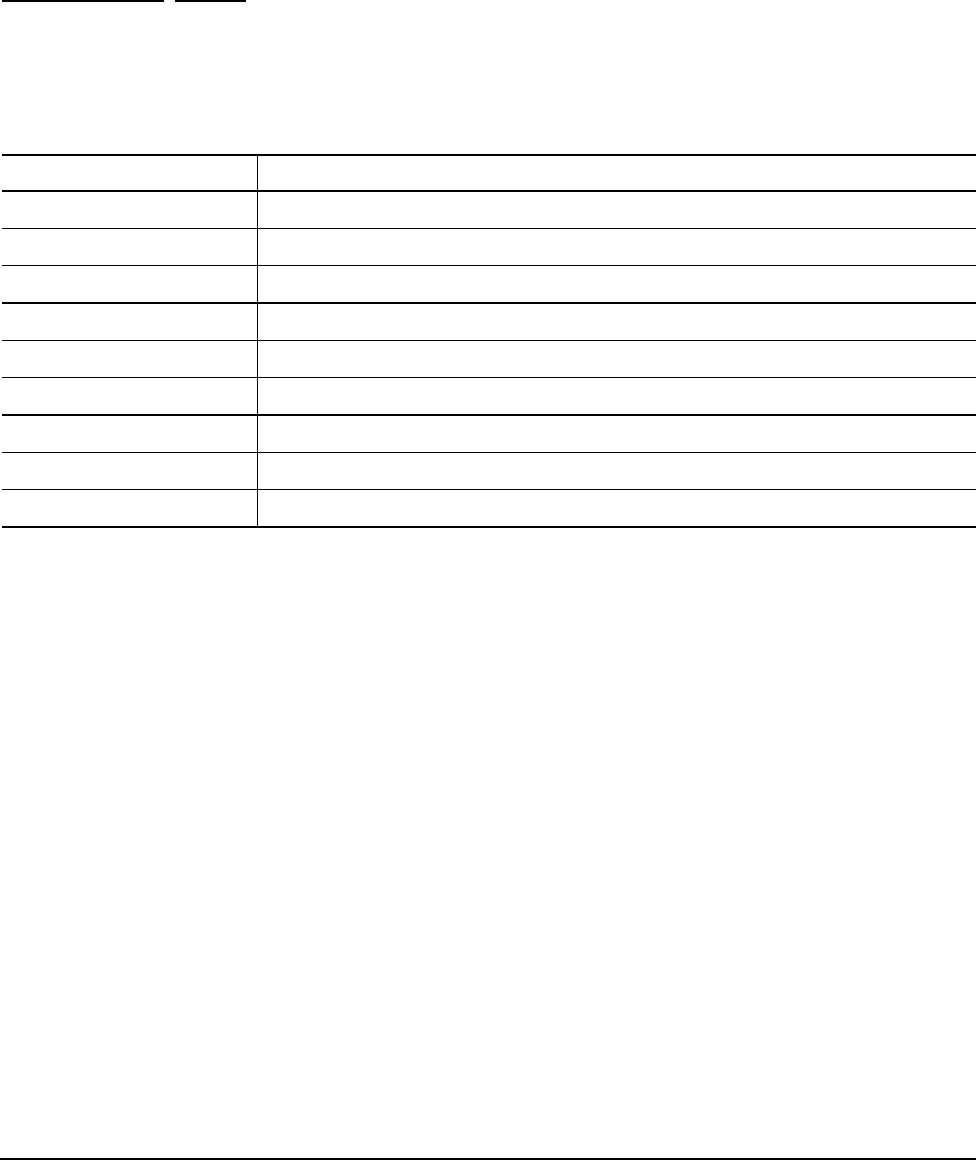
38
Momentus 5400 FDE.3 SATA Product Manual, Rev. A
4.2.7 S.M.A.R.T. commands
S.M.A.R.T. provides near-term failure prediction for disc drives. When S.M.A.R.T. is enabled, the drive moni-
tors predetermined drive attributes that are susceptible to degradation over time. If self-monitoring determines
that a failure is likely, S.M.A.R.T. makes a status report available to the host. Not all failures are predictable.
S.M.A.R.T. predictability is limited to the attributes the drive can monitor. For more information on S.M.A.R.T.
commands and implementation, see the Draft ATA-5 Standard.
SeaTools diagnostic software activates a built-in drive self-test (DST S.M.A.R.T. command for D4H) that elimi-
nates unnecessary drive returns. The diagnostic software ships with all new drives and is also available at:
http://seatools.seagate.com.
This drive is shipped with S.M.A.R.T. features disabled. You must have a recent BIOS or software package that
supports S.M.A.R.T. to enable this feature. The table below shows the S.M.A.R.T. command codes that the
drive uses.
Note. If an appropriate code is not written to the Features Register, the command is aborted and 0x 04
(abort) is written to the Error register.
Table 11: S.M.A.R.T. commands
Code in features register S.M.A.R.T. command
D0HS.M.A.R.T. Read Data
D1HVendor-specific
D2HS.M.A.R.T. Enable/Disable Attribute Autosave
D3HS.M.A.R.T. Save Attribute Values
D4HS.M.A.R.T. Execute Off-line Immediate (runs DST)
D7HVendor-specific
D8HS.M.A.R.T. Enable Operations
D9HS.M.A.R.T. Disable Operations
DAHS.M.A.R.T. Return Status
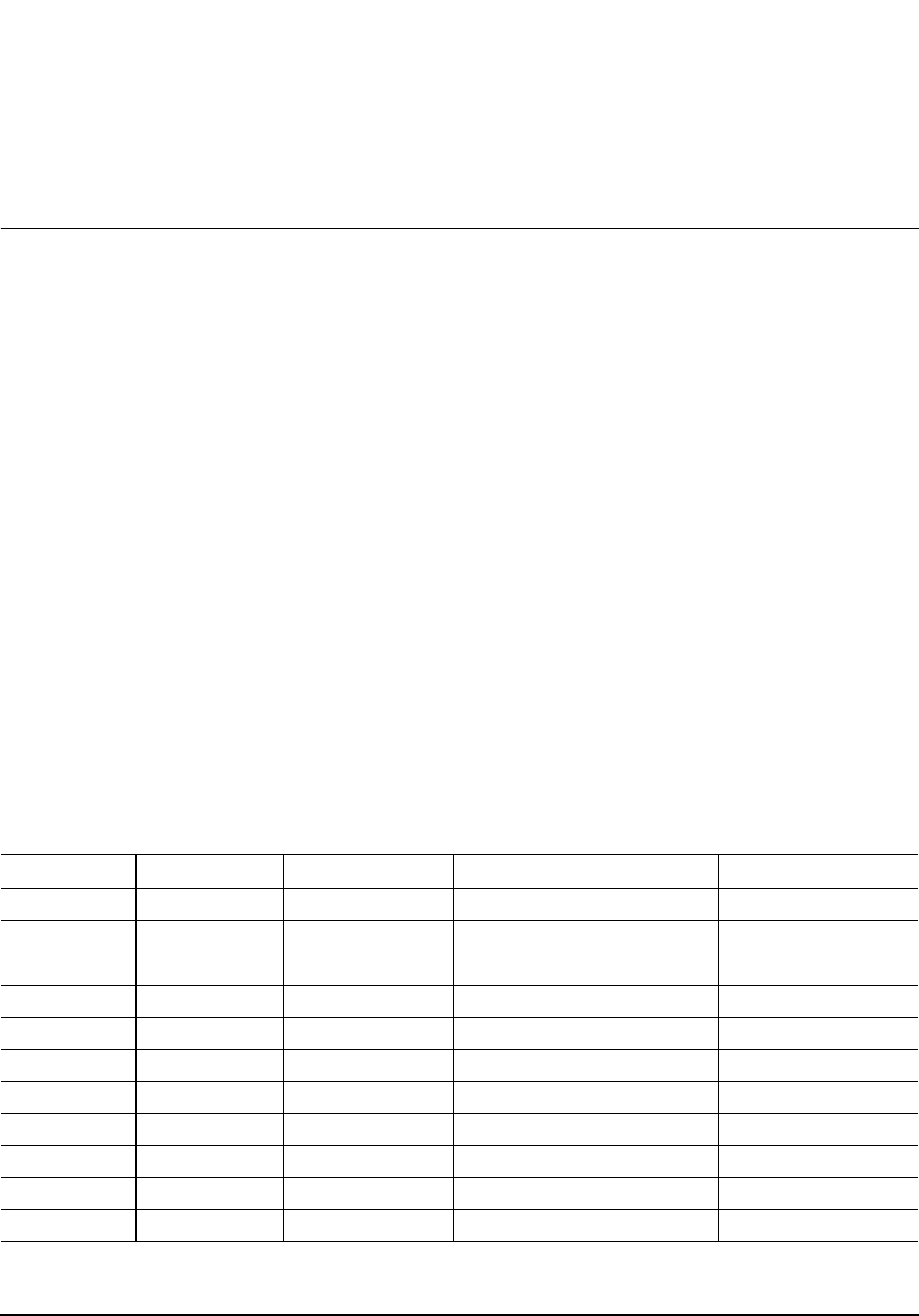
Momentus 5400 FDE.3 SATA Product Manual, Rev. A
39
5.0 Compatibility summary
5.1 Installation considerations
Many of today’s mobile computers have been designed to make it possible for the end user to replace the hard
drive. Refer to your system’s user manual for the location of the hard drive compartment and the specific
instructions regarding replacement. Refer to your system manufacturer’s support website for the most up-to-
date information. Read and follow all instructions regarding the proper steps to be taken when replacing the
system hard drive.
Some mobile systems are sealed and require specialized tools to gain access to the hard drive. Special train-
ing or tools may be needed to service some mobile computers. In some cases, opening the case may void
your warranty. Consult your system documentation. Seagate recommends taking your system to an authorized
service technician to replace your hard drive.
5.2 System Compatibility using WIndows XP SP2
Seagate Product Assurance has tested Momentus drives in systems using ATA Security mode. Testing
included multiple BIOS versions and the Windows XP SP2 Pro operating system. This testing was done to
demonstrate compatibility with various hardware and software configurations.
5.2.1 BIOS versions tested in ATA Security mode
The following list indicates the types of BIOS Seagate tested during the compatibility testing process. The list
highlights the major BIOS manufacturers. Individual systems contain variations of these BIOS versions and
were tested with regard to their implementation in the individual systems.
Table 12: Tested BIOS versions with Windows XP SP2
Manufacturer Model BIOS Vendor BIOS Release BIOS Version
AMD K8 AMI MSIA7207NMS V3.00
AMD K8 AMI V02.59
AMD K8 AMI VER 02.59 VER 08.00.13
AMD K8 AWARD 6 P6
AMD K8 AWARD V1.B 11/28/2005
AMD K8 AWARD V6.00 P0
AMD K8 AWARD V6.00PG
AMD K8 AWARD V6.00PG 11/17/2005
AMD K8 HP 786B9 V2.00
AMD K8 PHOENIX AWARD VER 6.00PG
AMD K8 PHOENIX 6.00P

40
Momentus 5400 FDE.3 SATA Product Manual, Rev. A
AMD K8 PHOENIX AWARD V5.1.39
AMD K8 PHOENIX AWARD V6.00PG
AMD K8 PHOENIX AWARD
AMD K8 PHOENIX DELL 1.1.2
AMD K8 PHOENIX VER 2004Q3
AMD K8 PHOENIX
ATI 0X5A31 INSYDE R1.00
ATI RS400-200 AMI V02.59
ATI RS400-200 AMI V0707
ATI RS480 AMERICAN
MEGETRENDS 2/13/2006
ATI RS480 AMI VER V3.1
ATI RS480 AWARD 3.13 11/15/2005
ATI RS480 HP VER1.09 11/22/2005
ATI RS480 PHOENIX V1.04
ATI RS480 PHOENIX AWARD V1.04 5/24/2005
INTEL 5000X PHOENIX DELL A00
INTEL 865 GATEWAY 510A 15A.0027
INTEL 865 GATEWAY 510A 15A.0043
INTEL 865 GATEWAY 510A 15A.0045
INTEL 865 GATEWAY 510A 15A.0066
INTEL 865 HP 786B1 V1.14
INTEL 865 HP 786B2 2.43
INTEL 865 HP 786B2 V1.11
INTEL 865 HP 786B2 V2.04
INTEL 865 HP 1.11
INTEL 865 HP 786B2 V1.10
INTEL 865 IBM 2CKT20AUS 10/26/2004
INTEL 865 INTEL 510A.86A.0053
INTEL 865 MICRON 510A.86A.003
INTEL 865 MICRON 510A.86A.0033
INTEL 865 PHOENIX DELL A04
INTEL 865 PHOENIX DELL A06
INTEL 865 PHOENIX DELL A08
INTEL 865 PHOENIX DELL A10
INTEL 865 PHOENIX 6
INTEL 875P AWARD 4/23/2003 875P-6A79BG00C
Table 12: Tested BIOS versions with Windows XP SP2
Manufacturer Model BIOS Vendor BIOS Release BIOS Version

Momentus 5400 FDE.3 SATA Product Manual, Rev. A
41
INTEL 875P GATEWAY 510A.15A.0080
INTEL 875P HP 786B3 V1.09
INTEL 875P MICRON 510A.86A.0076
INTEL 875P PHOENIX DELL A02
INTEL 875P PHOENIX DELL A03
INTEL 915G/P AMI 3.1 8.00.10 11/12/04
INTEL 915G/P AMI VVPGI635 5/6/2004
INTEL 915G/P AMI VVPGI635
INTEL 915G/P HP 786C1 V1.05
INTEL 915G/P HP 786C2 V1.02
INTEL 915G/P IBM 2/4/2005
INTEL 915G/P MPC EV91510A.86A.0308
INTEL 915G/P PHOENIX AWARD BIOS 6.00PG R01-03
INTEL 915G/P PHOENIX DELL A01
INTEL 915G/P PHOENIX DELL A03
INTEL 915G/P PHOENIX DELL A05
INTEL 915M AMI R0060F2
INTEL 915M IBM 1.03A (77ET40WW)
INTEL 915M PHOENIX 30/05/2005 1.05
INTEL 915M PHOENIX PHOENIX BIOS 1.06
INTEL 915M PHOENIX 1.07
INTEL 915M PHOENIX R0071V0
INTEL 915M PHOENIX R0160X5
INTEL 925X HP 786C3 V1.04
INTEL 925X PHOENIX DELL A06
INTEL 945G/P AWARD NT94510J.86A.2487.2005.0906.
1451
INTEL 945G/P HP 786D1 V1.03
INTEL 945G/P PHOENIX AWARD V6.00PG
INTEL 945G/P PHOENIX DELL A01
INTEL 945G/P PHOENIX DELL A02
INTEL 945G/P PHOENIX DELL A05
INTEL 945GM/PM DELL A02
INTEL 945GM/PM DELL A04
INTEL 945GM/PM DELL A05
INTEL 945GM/PM DELL A09
INTEL 945GM/PM HP F.05
Table 12: Tested BIOS versions with Windows XP SP2
Manufacturer Model BIOS Vendor BIOS Release BIOS Version

42
Momentus 5400 FDE.3 SATA Product Manual, Rev. A
5.2.2 DriveTrust compatibility verification
The systems documented in Table 13 passed DriveTrust compatibility tests running Windows XP Pro with ser-
vice pack 2 (SP2). The system configurations listed below support the Trusted Send/Receive capabilities
required for pre-boot and other SeaCOS (dcard) features. Refer to your DriveTrust software vendor for addi-
tional considerations.
INTEL 945GM/PM IBM 1.02 (79ET56WW)
INTEL 945GM/PM IBM 1.04 (7BET44WW)
INTEL 945GM/PM LENOVO 1.02 (7CET47WW)
INTEL 945GM/PM LENOVO 1.10 (7FET50WW)
INTEL 945GM/PM LENOVO 2.00 (79ETC0WW)
INTEL 945GM/PM PHOENIX V1.20
INTEL 955X AMI 206 12/21/2005
INTEL 955X HP 786D3 V1.02
INTEL 955X PHOENIX AWARD W7158IMS
INTEL 955X
INTEL 975X AMI 206 12/21/2005
INTEL 975X AWARD VER F1
INTEL E7221 PHOENIX DELL A00
INTEL G/P965 INSYDE
INTEL G/P965 PHOENIX 1.0.3 8/14/2006
INTEL G/P965 PHOENIX DELL 1.0.3
INTEL G/P965 PHOENIX DELL 2.1.0
NVIDIA 0X0070 PHOENIX V6.00PG 2/7/2006
NVIDIA NFORCE 4SLI AMI V310
NVIDIA NFORCE 4SLI PHOENIX DELL A04
NVIDIA NFORCE 4SLI PHOENIX V6.00PG 7/11/2005
SIS 661 AWARD R1.00 6/13/2005
SIS 760 AMI V2.54
SIS 760 PHOENIX V3.01 8/18/2004
VIA K8M800 AMI V0210
VIA K8M800 AMI V2.54 8/30/2005
VIA K8M800 AWARD V6.00PG 10/17/2005
Table 12: Tested BIOS versions with Windows XP SP2
Manufacturer Model BIOS Vendor BIOS Release BIOS Version
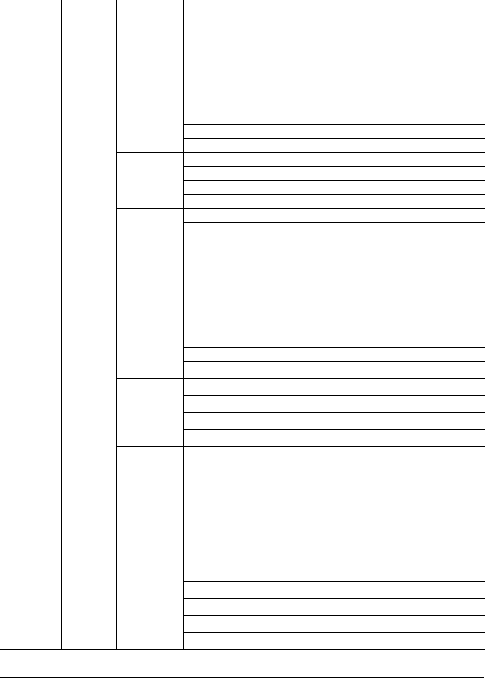
Momentus 5400 FDE.3 SATA Product Manual, Rev. A
43
Table 13: DriveTrust compatibility
Chipset
Manufacturer Chipset
Southbridge System Vendor System Model SATA Mode BIOS
Intel ICH6M LG LW40-DOX1 ATA Phoenix OLMPSF07
TCL K40D ATA Phoenix1.00
ICH7M Acer Aspire 3690 BL50 ATA Phoenix V3.50
Aspire 5572WXMI ATA Phoenix V1.3505
Aspire 9410 MS2195 ATA Phoenix V1.18
Aspire 9800 LA01 ATA Phoenix I1.05
Aspire 9815WKH1 ATA Phoenix V2.12
Travelmate 3270-ZR1 ATA Phoenix V1.3505
6263 ATA Phoenix 2.03
Asus F9J ATA Asus
G2P ATA Asus 009.012.001.027.A07408.025
R1F ATA Asus 13.13.I06405.009
V1JP ATA Asus V310
Dell Inspiron 6400/E1505 ATA Dell A09
Inspiron 9400/E1705 ATA Dell A04
Precision M65 ATA Dell A05
Precision M90 ATA Dell A04
XPS M1210 ATA Dell A04
XPS M1710 ATA Dell A02
Fujitsu FMVNE2KD3 AHCI Phoenix V1.09
FMVNF70W AHCI Fujitsu Phoenix 1.04
FMVNS5C4 AHCI Fujitsu Phoenix 1.25
FMVNX70WD AHCI Fujitsu Phoenix 1.06
FMVNX90RW AHCI Phoenix V1.04
Lifebook FMV8250 ATA Phoenix V1.02
Gateway E-100M AHCI PhoenixBIOS 76.09
M465-E AHCI PhoenixBIOS 71.04
M685-E AHCI PhoenixBIOS 72.02
NX560X AHCI PhoenixBIOS 71.04
HP-BPC Compaq NC4400 AHCI HP F.08
Compaq NC6400 AHCI HP F.08
Compaq NC8430 AHCI HP F.12
Compaq NW8440 AHCI HP F.12
Compaq NW9440 AHCI HP F.1B
Compaq NX7400 AHCI HP
Compaq NX8420 AHCI HP F.15
Compaq NX9420 AHCI HP F.1C
Compaq TC4400 AHCI HP F.0B
Pavilion DV2000T AHCI HP F26
Pavilion DV6000T AHCI HP F27
Pavilion DV9000T AHCI HP F27
44
Momentus 5400 FDE.3 SATA Product Manual, Rev. A
Intel ICH7M HP-BPC Presario V3000T AHCI HP F26
Presario V6000T AHCI HP F.29
Lenovo China Sunrise 210 ATA Phoenix Trustedcore 1.0B-
1264-8A20
Sunrise 410 ATA Phoenix Trustedcore LE4
Q3B72
Sunrise 410L ATA Phoenix Trustedcore LE4
Q3B72
TIAN YI F30A ATA Phoenix Trustedcore Q3A82
TIAN YI F40A ATA V1.08
LG LGE-DMLGR40(B) AHCI Phoenix LHONSF04
NEC-SAS NEC Versa M160 ATA Phoenix 3A22-1284-1A22
NEC Versa M360 ATA Phoenix 3A22-1284-1A22
Sony VGN FE31B/W ATA Phoenix R0170J3
VNG FE51B/H ATA Phoenix R0107J3
VGN-AR92S ATA Phoenix
VGN-C71B/W ATA Phoenix
VGN-FE53B/W ATA Phoenix
VGN-N51HB ATA Phoenix
VGN-SZ73B/B ATA Phoenix N0G72-13
TCL K42 ATA Phoenix 1.08
Toshiba Satelite M100 ATA Phoenix V1.20
ICH8M Acer AS9920 AHCI Phoenix V1.11.0
Aspire 4720 AHCI Phoenix V1.08
Aspire 5920G AHCI Phoenix V1.3708
Aspire 5920G AHCI Acer
Aspire 7720WSMI AHCI AMI V1.12
Asus G1S AHCI Asus
G2S ATA Asus 1000B50001
Dell Inspiron 1420 AHCI Phoenix A00
Inspiron 1720 AHCI Phoenix A00
Precision M4300 ATA Phoenix A02
Precision M6300 AHCI Phoenix A00
Fujitsu FMB BIBLO NF70X AHCI Phoenix V1.12
FMVNE5FD4 AHCI Fujitsu Phoenix 1.06
Fujitsu
Siemens Celsius H250 AHCI Phoenix 1.08
Lifebook S6410 AHCI Phoenix 1.11
Table 13: DriveTrust compatibility
Chipset
Manufacturer Chipset
Southbridge System Vendor System Model SATA Mode BIOS
Momentus 5400 FDE.3 SATA Product Manual, Rev. A
45
Intel ICH8M HP-BPC Compaq 2210B AHCI HP F00
Compaq 6510B AHCI HP F10
Compaq 6710B AHCI HP F.0B
Compaq 6720S AHCI HP
Compaq 6910P AHCI HP F.06
Compaq 8710P AHCI
Pavilion DV2500T AHCI Phoenix F.21
Pavilion DV6500T AHCI Phoenix F.33
Pavilion DV9500T AHCI Phoenix F.33
Pavilion HDX AHCI HP
Levovo China TIANYI F41A ATA Lenovo 05N23WW (V1.03)
XURI C430A ATA Lenovo Q3B14
XURI C430G ATA Lenovo Q3B14
ZHAOYANG K42A AHCI Lenovo 1.06T05
LG LGE-DML GE50(B) ATA AMI A1636IL 1 V1.17
LGE-DML GM1(B) ATA Phoenix STNYSF05
LGE-DML GP3 AHCI Phoenix COLSSF0B
Samsung SEC-NT-R70(B) ATA Phoenix 05AB
SQ45S70S ATA Phoenix 06ST
TCL T45 AHCI Phoenix A 0B-0401-0011
Trigem N8393WFGK ATA Phoenix 1.00TG
AMD(ATI) SB600 Acer Travelmate 5520G ATA Phoenix V1.14
Dell Inspiron 1521 ATA Phoenix A00
Inspiron 1721 ATA Phoenix 2 3.1
Trigem N8172SH1K ATA Phoenix 1.00
Dell Inspiron 1501 ATA Dell 1.4.0
Nvidia MCP51 HP-BPC Pavilion DV2000Z ATA HP F34
Pavilion DV6000Z ATA HP F38
Pavilion TX1000Z ATA HP F.18
Nvidia MCP51 HP-BPC Pavilion TX1200 ATA Phoenix F.1C
Presario V6000Z ATA HP F.38
Table 13: DriveTrust compatibility
Chipset
Manufacturer Chipset
Southbridge System Vendor System Model SATA Mode BIOS

46
Momentus 5400 FDE.3 SATA Product Manual, Rev. A
5.3 Operating system versions tested
This list indicates the types of Operating Systems Seagate tested during the compatibility testing process. Sev-
eral variations of these operating systems have been tested.
5.4 Compatibility test configurations
Tests are performed to ensure functionality to the ATA/ATAPI-7 specification and are constantly evolving to
match the evolution of the ATA/ATAPI specifications. Momentus 5400 FDE.3 SATA drives should be expected
to be largely compliant to the emerging ATA/ATAPI-8 specification.
Exceptions to the specifications for the Momentus 5400 FDE.3 SATA drives are listed in Section 4.0.
Table 14: Supported operating systems
Manufacturer Version/Release
Microsoft Windows Server 2003 (Compatibility evaluated, but not tested)
Microsoft Windows XP, XP Pro, XP Home (Service Pack 2) (multiple languages)
Microsoft Windows Vista.
Note: Some systems will require a “hotfix” from Microsoft. Refer to www.miocrosoft.com and
search for knowledgebase (KB) article number 943170 for important information about obtaining
and installing the necessary operating system fixes necessary to successfully use Vista with FDE
drives in DriveTrust mode. These fixes are not required to use the drive in ATA Security mode.

Momentus 5400 FDE.3 SATA Product Manual, Rev. A
47
6.0 Seagate Technology support services
Internet
For information regarding Seagate products and services, visit www.seagate.com. Worldwide support is
available 24 hours daily by email for your questions.
Presales Support:
Presales@Seagate.com
Technical Support:
DiscSupport@Seagate.com
Warranty Support:
http://www.seagate.com/support/service/index.html
mySeagate
my.seagate.com is the industry's first Web portal designed specifically for OEMs and distributors. It provides
self-service access to critical applications, personalized content and the tools that allow our partners to
manage their Seagate account functions. Submit pricing requests, orders and returns through a single,
password-protected Web interface-anytime, anywhere in the world.
spp.seagate.com
spp.seagate.com supports Seagate resellers with product information, program benefits and sales tools. You
may register for customized communications that are not available on the web. These communications contain
product launch, EOL, pricing, promotions and other channel-related information. To learn more about the
benefits or to register, go to spp.seagate.com, any time, from anywhere in the world.
Seagate Service Centers
Presales Support
Our Presales Support staff can help you determine which Seagate products are best suited for your specific
application or computer system, as well as product availability and compatibility.
Technical Support
Seagate technical support is available to assist you online at support.seagate.com or through one of our call
centers. Have your system configuration information and your “ST” model number available.
SeaTDD™ (+1-405-324-3655) is a telecommunications device for the deaf (TDD). You can send questions or
comments 24 hours daily and exchange messages with a technical support specialist during normal business
hours for the call center in your region.

48
Momentus 5400 FDE.3 SATA Product Manual, Rev. A
Customer Service Operations
Warranty Service
Seagate offers worldwide customer support for Seagate products. Seagate distributors, OEMs and other direct
customers should contact their Seagate Customer Service Operations (CSO) representative for warranty-
related issues. Resellers or end users of drive products should contact their place of purchase or Seagate
warranty service for assistance. Have your serial number and model or part number available.
Data Recovery Services
Seagate offers data recovery services for all formats and all brands of storage media. Our data recovery
services labs are currently located throughout the world. . Additional information, including an online request
form and data loss prevention resources, is available at http://services.seagate.com/index.aspx
Authorized Service Centers
Seagate Service Centers are available on a global basis for the return of defective products. Contact your
customer support representative for the location nearest you.
USA/Canada/Latin America support services
For an extensive list of telephone numbers to technical support, presales and warranty service in USA/
Canada/Latin America, including business hours, go to the "Contact Us" page on www.seagate.com.
Global Customer Support
Presales, Technical, and Warranty Support
Call Center Toll-free Direct dial
USA, Canada,
and Mexico 1-800-SEAGATE +1-405-324-4700
Data Recovery Services
Call Center Toll-free Direct dial FAX
USA, Canada, 1-800-475-01435 +1-905-474-2162 1-800-475-0158
and Mexico +1-905-474-2459
Europe, the Middle East and Africa Support Services
For an extensive list of telephone numbers to technical support, presales and warranty service in Europe, the
Middle East and Africa, go to the "Contact Us" page on www.seagate.com.
Asia/Pacific Support Services
For an extensive list of telephone numbers to technical support, presales and warranty service in Asia/Pacific,
go to the "Contact Us" page on www.seagate.com.

Momentus 5400 FDE.3 SATA Product Manual, Rev. A
49
Index
A
ACA 17
acoustics 6, 15
Active mode 12
AFR 16
Agency certification 16
Altitude 13
Altitude, nonoperating 6
Altitude, operating 6
Ambient temperature 6, 13
ambient temperature 9
Annualized Failure Rate 16
Annualized Failure Rate (AFR) 6
Areal density 5, 8
ATA data-transfer modes supported 5
ATA-standard commands 30
Australia/New Zealand Standard AS/NZS3548 1995
17
Australian Communication Authority (ACA) 17
Australian C-Tick 17
Average seek time 9
Average seek, read 5
B
bels 6
BIOS manufacturers 39
BPI 5
buffer 1, 5, 8
burst 1
Bytes per sector 5, 7
C
cables and connectors 20
Cache 5
cache 1, 8
capacity 7
case temperature 13
CE mark 16
certification 16
chemical substances 18
China RoHS directive 18
Class B computing device 17
commands 30
compatibility 16, 39
compatibility summary 39
compatibility test configurations 46
Conducted noise 11
Conducted RF immunity 15
Configuring the drive 19
connectors 20
CSA C22.2 (950) 16
current 5
cycles 16
Cylinders 7
D
data-transfer rates 1
DC power 10
Default logical geometry 7
density 5
diagnostic software 1
dimensions 21
Discs 5
dissipation 10
drive monitoring 1
drive self-test 1
E
Electrical fast transient 15
Electromagnetic compatibility 16
Electromagnetic Compatibility Directive (89/336/EEC)
16
Electromagnetic immunity 15
Electrostatic discharge 15
electrostatic discharge (ESD) 19
EN 55022, Class B 16
EN 55024 16
EN 60950 16
Environmental protection 18
Environmental specifications 13
error-correction algorithms 1
errors 6, 16
ESD 19
EU 16
European Union (EU) requirements 16
European Union Restriction of Hazardous Substanc-
es 18
F
FCC verification 17
Federal Communications Commission 17
Formatted capacity 7
Formatted Gbytes 5
G
Gbytes 7
geometry 7
gradient 6
Guaranteed sectors 5, 7
guaranteed sectors 7
H
handling 19
Handling precautions 19

50
Momentus 5400 FDE.3 SATA Product Manual, Rev. A
heads 7
Height 5
height 8
Humidity 13
humidity 6
I
I/O data-transfer rate 5, 8
Identify Device command 34
Idle 10
Idle and Standby timers 12
Idle mode 6, 12
Idle mode power 10
IEC950 16
Information Technology Equipment (ITE) 16
Input noise ripple 11
Interface 8
interface 25
Interleave 8
Internal data transfer rate 5
Internal data-transfer rate 8
ITE 16
K
Korean RRL 17
L
latency 5
LBA mode 7
Length 5
length 8
Load/Unload 16
logical geometry 7
M
maximum temperature 13
monitoring 1
mounting 21
mounting screws 14
mounting the drive 19
N
noise 11
nominal power 9
Nonoperating shock 14
Nonoperating vibration 14
Nonrecoverable read errors 6
nonrecoverable read errors 16
O
Operating shock 14
operating system 39
Operating vibration 14
OS manufacturers 46
P
Physical characteristics 8
Physical organization 8
Physical read/write heads 5
point-to-point 20
Power consumption 10
power dissipation 10
power management 12
power on/off cycles 16
Power specifications 10
Power-management modes 12
Power-on to Ready 9
Power-on to ready 5
precautions 19, 21
programmable power management 12
Q
quick reference 5
R
Radiated RF immunity 15
Radio and television interference 17
radio frequency (RF) 15
random track location 10
read errors 6, 16
Read Multiple 1
Read/write heads 7
Read/write power 5
read/write power and current 10
Recording density 5, 8
Recording method 8
Recording technology 8
Relative humidity 6, 13
Reliability 16
resistance 11
RF 15
RoHS 18
RPM 5
RRL 17
S
S.M.A.R.T. drive monitoring 1
Safety certification 16
SATA 8, 25
screws 14, 21
SeaTools 1
sector 7
sectors 7
Sectors per track 7
seek mode 10

Momentus 5400 FDE.3 SATA Product Manual, Rev. A
51
Seek power 5
Seek time 9
seek time 5
Seeking 10
Self refresh, low power 12
Serial ATA 8
Serial ATA (SATA) interface 25
servo electronics 10
Shock 14
Shock, nonoperating 6
Shock, operating 6
single-track seeks 9
Sleep 10
Sleep mode 6, 12
sound power 6
Specification summary table 5
Spindle speed 5, 8
Spinup 10
spinup power 10
Standby 10
Standby mode 6, 10, 12
Standby to Ready 9
Standby to ready 5
Start/stop times 9
Startup current 5
static-discharge 19
support services 47
Surge immunity 15
T
technical support services 47
temperature 6, 9, 13
Temperature gradient 6, 13
timers 12
TPI 5
Track density 5, 8
Track-to-track seek time 5, 9
TUV North America 16
U
UL 1950 16
V
Vibration 14
Vibration, nonoperating 6
Vibration, operating 6
Voltage dips, interrupts 15
Voltage tolerance 6, 11
W
Warranty 16
Weight 5
weight 8
Wet bulb temperature 6, 13
Width 5
width 8
Write Multiple 1

52
Momentus 5400 FDE.3 SATA Product Manual, Rev. A

Seagate Technology LLC
920 Disc Drive, Scotts Valley, California 95066-4544, USA
Publication Number: 100513273, Rev. A, Printed in USA
